Avaya Canada NTMQ75AA User Manual 12 0152 antenna 1 02
Avaya Canada Corporation 12 0152 antenna 1 02
Contents
Antenna

Picocell 1900 Antenna System
Installation
Installation Method – 12-0152
September 4, 1998
Issue Number 1.02
Information subject to change without notice. This is a DRAFT copy
for review and to provide advance information. Document release
subject to IM verification. Errors, omissions and corrections should be
sent to: lthomp@nortel.com
Pkgid: 0000003
PROPRIETARY INFORMATION: The information contained in this document
is the property of Northern Telecom. Except as specifically authorized in
writing, the holder of this document shall keep all information contained herein
confidential and shall protect same in whole or in part from disclosure and
dissemination to third parties.
© Northern Telecom 1998
All Rights Reserved

2 / Picocell 1900 Antenna System Installation
Method 12-0152 September 4, 1998
Draft
Reason for Reissue: Draft Release
Comments:
Release Date:
Updated By:
Co-Author at RTP:
Co-Author at BRW:
Co-Author at RICH:
Reason for Reissue:
Comments:

Picocell 1900 Antenna System Installation / 3
September 4, 1998 Method 12-0152
Draft
Contents
1.0 General Information . . . . . . . . . . . . . . . . . . . . . . . . . . . . . . . . . . . . . . . . . . . . . . . . . . . . . . . 6
1.1 Description . . . . . . . . . . . . . . . . . . . . . . . . . . . . . . . . . . . . . . . . . . . . . . . . . . . . . . . . . . . . 6
1.2 Reason for Reissue . . . . . . . . . . . . . . . . . . . . . . . . . . . . . . . . . . . . . . . . . . . . . . . . . . . . . . 6
1.3 Reason for Reissue . . . . . . . . . . . . . . . . . . . . . . . . . . . . . . . . . . . . . . . . . . . . . . . . . . . . . 7
2.0 Material Requirements . . . . . . . . . . . . . . . . . . . . . . . . . . . . . . . . . . . . . . . . . . . . . . . . . . . . . 8
2.1 Required Documents . . . . . . . . . . . . . . . . . . . . . . . . . . . . . . . . . . . . . . . . . . . . . . . . . . . . 8
2.2 Tools.
Supplies . . . . . . . . . . . . . . . . . . . . . . . . . . . . . . . . . . . . . . . . . . . . . . . . . . . . . . . . . . . . . . 9
2.3 Forms . . . . . . . . . . . . . . . . . . . . . . . . . . . . . . . . . . . . . . . . . . . . . . . . . . . . . . . . . . . . . . . 10
2.4 Parts List . . . . . . . . . . . . . . . . . . . . . . . . . . . . . . . . . . . . . . . . . . . . . . . . . . . . . . . . . . . . . 10
3.0 Precautions and Preparations . . . . . . . . . . . . . . . . . . . . . . . . . . . . . . . . . . . . . . . . . . . . . . 11
3.1 Precautions . . . . . . . . . . . . . . . . . . . . . . . . . . . . . . . . . . . . . . . . . . . . . . . . . . . . . . . . . . . 11
3.2 Preparations . . . . . . . . . . . . . . . . . . . . . . . . . . . . . . . . . . . . . . . . . . . . . . . . . . . . . . . . . . 11
3.3 Sequence . . . . . . . . . . . . . . . . . . . . . . . . . . . . . . . . . . . . . . . . . . . . . . . . . . . . . . . . . . . . 11
4.0 Procedure . . . . . . . . . . . . . . . . . . . . . . . . . . . . . . . . . . . . . . . . . . . . . . . . . . . . . . . . . . . . . . 12
4.1 Overview . . . . . . . . . . . . . . . . . . . . . . . . . . . . . . . . . . . . . . . . . . . . . . . . . . . . . . . . . . . . . 12
Dual 4 Port Hybrid . . . . . . . . . . . . . . . . . . . . . . . . . . . . . . . . . . . . . . . . . . . . . . . . . . . . . 12
Dual 8 port Hybrid . . . . . . . . . . . . . . . . . . . . . . . . . . . . . . . . . . . . . . . . . . . . . . . . . . . . . . 13
5.0 Mounting the Hybrid(s) . . . . . . . . . . . . . . . . . . . . . . . . . . . . . . . . . . . . . . . . . . . . . . . . . . . . 14
Procedure 1 – Mounting the Hybrid: . . . . . . . . . . . . . . . . . . . . . . . . . . . . . . . . . . . . 15
6.0 Picocell 1900 Antennas . . . . . . . . . . . . . . . . . . . . . . . . . . . . . . . . . . . . . . . . . . . . . . . . . . . 18
Antenna Mounting hardware kit . . . . . . . . . . . . . . . . . . . . . . . . . . . . . . . . . . . . . . . . . . . 18
Procedure 2 – Ceiling Mount Omni Antennas . . . . . . . . . . . . . . . . . . . . . . . . . . . . 19
Procedure 3 – Mounting Directional Antenna and Wall Bracket . . . . . . . . . . . . . . . 20
7.0 Cable Types and Connectors . . . . . . . . . . . . . . . . . . . . . . . . . . . . . . . . . . . . . . . . . . . . . . 22
7.1 RF Cable Installation . . . . . . . . . . . . . . . . . . . . . . . . . . . . . . . . . . . . . . . . . . . . . . . . . . . . 23
Procedure 4 – Placement of RF Cable . . . . . . . . . . . . . . . . . . . . . . . . . . . . . . . . . . 24
7.2 RF Cable Connector Assembly . . . . . . . . . . . . . . . . . . . . . . . . . . . . . . . . . . . . . . . . . . . . 25
Procedure 5 – Preparing the Heliax cable: . . . . . . . . . . . . . . . . . . . . . . . . . . . . . . . 26
Procedure 6 – Flaring 3/8" and 1/2" cable/connector assemblies: . . . . . . . . . . . . . 31
Procedure 7 – Center Conductor Finishing . . . . . . . . . . . . . . . . . . . . . . . . . . . . . . . 32
Procedure 8 – Assembling the Connector Body . . . . . . . . . . . . . . . . . . . . . . . . . . . 33
7.3 References . . . . . . . . . . . . . . . . . . . . . . . . . . . . . . . . . . . . . . . . . . . . . . . . . . . . . . . . . . . 34
Appendix A - 4 Port Hybrid Insertion Losses . . . . . . . . . . . . . . . . . . . . . . . . . . . . . . . . . 35
Last Page . . . . . . . . . . . . . . . . . . . . . . . . . . . . . . . . . . . . . . . . . . . . . . . . . . . . . . . . . . . . 35

4 / Picocell 1900 Antenna System Installation
Method 12-0152 September 4, 1998
Draft
Illustrations
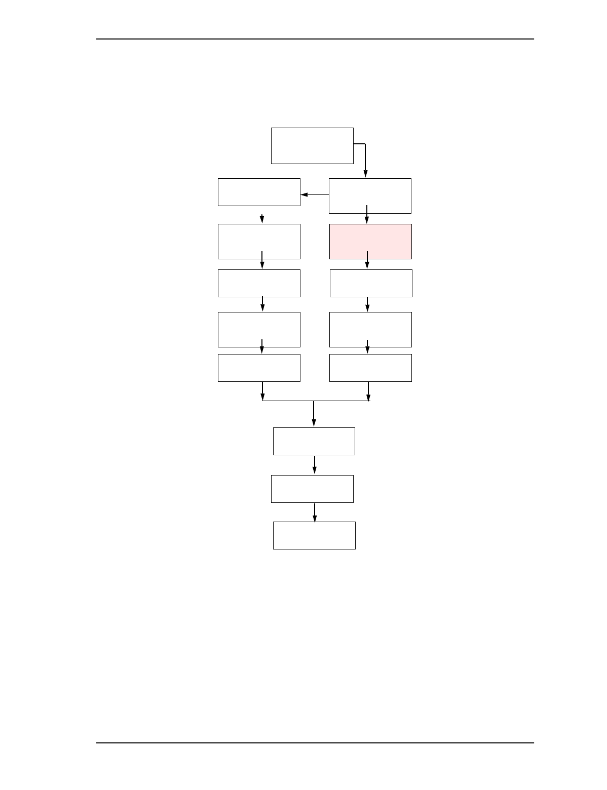
Figure 1 – You Are Here Diagram. . . . . . . . . . . . . . . . . . . . . . . . . . . . . . . . . . . . . . . . . . . . . . 7
Figure 2 – Single and Dual Picocell 1900 Antenna Configurations . . . . . . . . . . . . . . . . . . . .12
Figure 3 – Four unit Picocell 1900 Antenna Configuration. . . . . . . . . . . . . . . . . . . . . . . . . . 13
Figure 4 – Dual 8 Port Hybrid (CPC A0737243)) . . . . . . . . . . . . . . . . . . . . . . . . . . . . . . . . .14
Figure 5 – Dual 4 Port Hybrid (CPC A0735611) . . . . . . . . . . . . . . . . . . . . . . . . . . . . . . . . .15
Figure 6 – Dual 8 port Back board Mounting (Typical) . . . . . . . . . . . . . . . . . . . . . . . . . . . . . .16
Figure 7 – Dual 4 port Back board Mounting (Typical) . . . . . . . . . . . . . . . . . . . . . . . . . . . . . .17
Figure 8 – Directional (Cushcraft part number: S1857AMP10NF, CPC: A0736188 . . . . . . .18
Figure 9 – Omni Antenna (Cushcraft part number: SQ1853P12NF, CPC: A0735776 . . . . .18
Figure 10 – Omni Antenna Ceiling Mounting . . . . . . . . . . . . . . . . . . . . . . . . . . . . . . . . . . . . 19
Figure 11 – Directional Antenna Wall Mounting . . . . . . . . . . . . . . . . . . . . . . . . . . . . . . . . . .20
Figure 12 – Directional Antenna dimensions . . . . . . . . . . . . . . . . . . . . . . . . . . . . . . . . . . . . 21
Figure 13 – Outer Sheath Stripping Lengths . . . . . . . . . . . . . . . . . . . . . . . . . . . . . . . . . . . . .27
Figure 14 – . Cable With O Ring . . . . . . . . . . . . . . . . . . . . . . . . . . . . . . . . . . . . . . . . . . . . . . 27
Figure 15 – Cable With Gasket . . . . . . . . . . . . . . . . . . . . . . . . . . . . . . . . . . . . . . . . . . . . . . .28
Figure 16 – Clamping Nut . . . . . . . . . . . . . . . . . . . . . . . . . . . . . . . . . . . . . . . . . . . . . . . . . . .28
Figure 17 – Trim Outer Conductor . . . . . . . . . . . . . . . . . . . . . . . . . . . . . . . . . . . . . . . . . . . . 28
Figure 18 – Center Conductor Finishing . . . . . . . . . . . . . . . . . . . . . . . . . . . . . . . . . . . . . . .29
Figure 19 – Size The Inner Conductor . . . . . . . . . . . . . . . . . . . . . . . . . . . . . . . . . . . . . . . . .29
Figure 20 – Cable/Clamping Nut . . . . . . . . . . . . . . . . . . . . . . . . . . . . . . . . . . . . . . . . . . . . . .30
Figure 21 – Assembling the center pin and center conductor. . . . . . . . . . . . . . . . . . . . . . . . 32
Figure 22 – Final Assembly . . . . . . . . . . . . . . . . . . . . . . . . . . . . . . . . . . . . . . . . . . . . . . . . . .33

Picocell 1900 Antenna System Installation / 5
September 4, 1998 Method 12-0152
Draft
List Of Tables
Table 1 – Tool list . . . . . . . . . . . . . . . . . . . . . . . . . . . . . . . . . . . . . . . . . . . . . . . . . . . . . . . . . . 9
Table 2 – Supplies . . . . . . . . . . . . . . . . . . . . . . . . . . . . . . . . . . . . . . . . . . . . . . . . . . . . . . . . 10
Table 3 – Parts List . . . . . . . . . . . . . . . . . . . . . . . . . . . . . . . . . . . . . . . . . . . . . . . . . . . . . . . 10
Table 4 – Andrew Cable Types and Insertion Loss . . . . . . . . . . . . . . . . . . . . . . . . . . . . . . . 22
Table 5 – Andrew Connectors. . . . . . . . . . . . . . . . . . . . . . . . . . . . . . . . . . . . . . . . . . . . . . . . 23
Table 6 – Heliax Minimum Bending Radius . . . . . . . . . . . . . . . . . . . . . . . . . . . . . . . . . . . . . 23
Table 7 – Connector Torque Specifications . . . . . . . . . . . . . . . . . . . . . . . . . . . . . . . . . . . . . 25
Table 8 – Outer Seath Strip Length . . . . . . . . . . . . . . . . . . . . . . . . . . . . . . . . . . . . . . . . . . . 27
Table 9 – Outer Conductor Trim Lengths. . . . . . . . . . . . . . . . . . . . . . . . . . . . . . . . . . . . . . . 29
Table 10 – Center Conductor Trim Length. . . . . . . . . . . . . . . . . . . . . . . . . . . . . . . . . . . . . . . 30

6 / Picocell 1900 Antenna System Installation
Method 12-0152 September 4, 1998
Draft
1.0 General Information
1.1 Description
Purpose: To install the Public Microcell antenna system in an indoor
environment.
Caution: This method is to be used exclusively for an indoor
application; it does not support an outdoor antenna application.
Should you undertake an outdoor application, the following
procedures must be performed in accordance with Northern Telecom
grounding practices; in specific, Northern Telecom Standard 4122.
Antennas located outdoors must be provisioned with lightning
protectors (Northern Telecom Part Number NT3P21DA) where the
antenna cable enters the building, and must be connected to a low
impedance ground. For more information, refer to Northern Telecom
Standard 4122.
This Methods specifies Andrew type cables and connectors which are
recommended for the Picocell 1900 system. If equivalent cables have
been provisioned from other manufacturers refer to the instructions
provided with the types for cable and connectors provided..
Equipment:..... •1900 MHz indoor antennas
•Heliax RF cable
•N-type male connectors
•RF Combining Hybrids
•50 Ohm 1Watt Terminator.
Application: Both initial installs and extensions.
Service Impact: No impact for initial installs. Extensions will require
removing the affected partition from service.
1.2 Reason for Reissue
Changes from Project Team Review Sept 1, 1998:
• Updated sections 1.1, 3.3
• Revised figures 12 and 13
• Add appendix A
• redo of tables in section 7.1 to 7.2 for legibility
Picocell 1900 Antenna System Installation / 7
September 4, 1998 Method 12-0152
Draft
Figure 11 – You Are Here Diagram
1.3 Reason for Reissue
This is the initial release of this method.
IM 04-0242
Picocell 1900
General Information
and Plannng
Educate Yourself
IM 04-0241
CSI Installation and
Planning
Mount the back board
and plan lay out s Check the site and plan
the Job
IM02-0242
Picocell 1900
General Information
and Plannng
IM 04-0243
CSI Handling and
securing
Install the CSI bracket
and mount the CSI and
Picocell 1900 power
supplies
Install Picocell 1900
mounting bracket(s),
Hybrids and Antennas
IM02-0245, 12-0152
Picocell 1900 Unit
and Antenna
Installation
IM 04-0243
CSI Handling and
securing
Mount the CSI cross-
connect blocks
Make Picocell 1900
Connections and lock
into bracket
IM02-0245
Picocell 1900 Unit
Installation
IM 04-0244
Picocell 1900
Cabling and Cross
Connect
Cable the CSI to the
cross-connect blocks Jumper Picocell 1900 to
CSI and power supply
on cross-connect blocks
IM 04-0244
Picocell 1900
Cabling and Cross
Connect
IM 04-0246
Picocell 1900 Radio
and CSI Power up
Power up CSI Power up Picocell 1900
Radios and perform
commissioning test
IM 04-0246
Picocell 1900 Radio
and CSI Power up
Commission Picocell
1900 transceivers
IM28-0248
Radio Commisioning with
the IFR
Load CSI and Radio
software and run
diagnostics
IM28-0247
CSI Equipment Loading
and Diagnostics
Test Integrated System IM02-0249
Microcell System
Test

8 / Picocell 1900 Antenna System Installation
Method 12-0152 September 4, 1998
Draft
2.0 Material Requirements
2.1 Required Documents
Installation Safety Manual (ISM/IM0) - can be requested from the
Regional Tool Facility.
The Methods contained in this document provide the necessary
instructions to mount equipment and install cabling. This document is
not sufficient to permit the complete system installation as the system
design documents are required which list the RF design, floor plan and
layout.
A system design specification and layout must be provided by a
qualified RF or System Engineer. The design specification and layout
will define radio and antenna locations as well as cable types and cable
routing including:
• The location of the antennas, orientation and their position tolerances.
• The routes the cables should follow.
• The physical location of Picocell 1900 radios and Hybrids.
• RF Channel assignments and labeling scheme for cables and
connectors.
• Define coverage areas and cell partitions, RF losses, gains and power
levels.
• Specify Cable types and lengths for each size cable in each coverage
area.
• Connectivity charts indicating “Antenna–to–Hybrid” cabling
information indicating hybrid port assignments.
Note: The system design specification may call for configurations
which may conflict with information in this document. In these
cases the System design document shall supersede information
contained in this method unless specified otherwise.
Picocell 1900 Antenna System Installation / 9
September 4, 1998 Method 12-0152
Draft
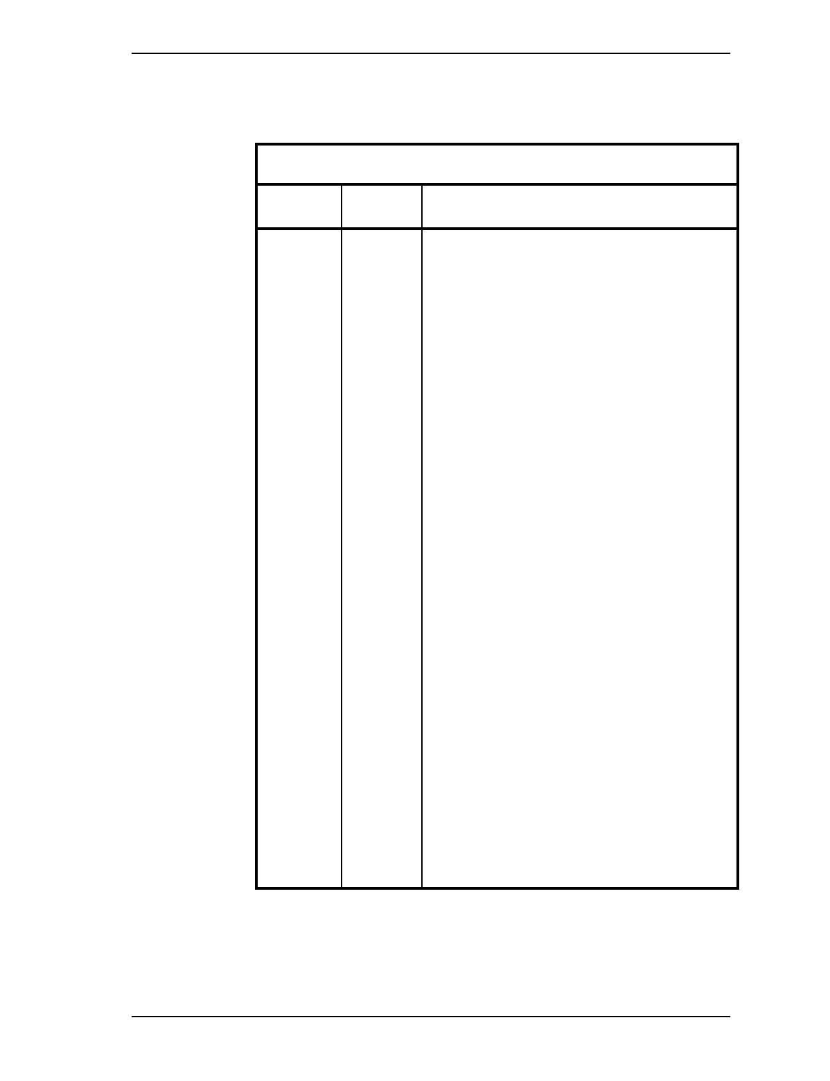
2.2 Tools.
Table 1 – Tool list
U.S.
Tools Canadian
Tools Description
Knife
Tack Hammer
Pliers
Damp Cloth
1000W Heat Gun
Wire Brush
Flat File
Portable Workbench
Solvent
Thin Angled Wire Snips
Fine Toothed Hacksaw
Andrew pin soldering pliers
Resistance soldering iron
or industrial soldering iron
Wrenches: 9/16", 19/32", 11/16
13/16", 3/4, two 21mm, one 24mm,
two adjustable wrenches, one
adjustable torque wrench
Straight screwdriver
3/8" Drill, assorted bits (inc. 1/4") and
1 1/4" hole cutter
Stepladder
- Andrew pin alignment tool
(Andrew p/n 224360):
used to straighten and
correctly orient the pin to the conductor.
- Resistance soldering iron:
if possible, this is
preferable to a normal soldering iron because it
heats faster, provides greater heat, and is easier
to use. If this is not an option use an industrial/
heavy use soldering iron.
- Andrew pin depth gauge for N-Male connectors
(Andrew p/n 224380):
used to establish that the
pin is set to the correct depth inside of the con-
nector.
- Andrew pin soldering pliers
(Andrew p/n 224377):
used to hold the contact
pin while it is being soldered.
10 / Picocell 1900 Antenna System Installation
Method 12-0152 September 4, 1998
Draft
Supplies
2.3 Forms
No forms are required to perform this method.
2.4 Parts List
See Table 4 on page 22 and Table 5 on page 23 for RF cables and
connectors
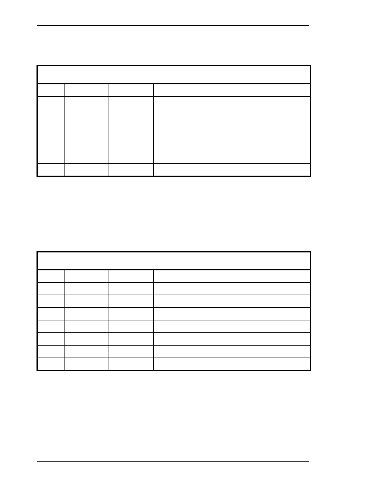
Table 2 –Supplies
Item PEC CPC Description
1Solder: 63/37 RMA flux core.
•Tape
•Garnet Cloth (240 or finer)
•Solvent: Comothene, Vythene or other non-flammable cleaning
fluid.
2
Table 3 – Parts List
Item PEC CPC Description
1 A0735776 Omni Ceiling Mount Antenna e/w N (f)
2 A0736188 Directional Wall mOunt Antenna e/w N (f)
3 A0735611 Dual 4 port Hybrid
4 A0737243 Dual 8 port Hybfid
5 A0600384 N-N (f-f) Adapter
6 B0241275 N(m) to TNC(m) RF cable 1.8M
7 A0609689 50 Ohm Termination

Picocell 1900 Antenna System Installation / 11
September 4, 1998 Method 12-0152
Draft
3.0 Precautions and Preparations
3.1 Precautions
Observe the general safety precautions against personal injury and
equipment damage outlined in the ISM/IM0 at all times.
3.2 Preparations
Prior to starting the operations presented in this method, arrange all
materials and tools at the work location so as to minimize fatigue and
inconvenience.
Inventory the installation components, documentation (installation
manual, floor plans and connectivity chart) and tools you will need.
This method contains tasks that require at least two people to carry them
out.
3.3 Sequence
This is a stand-alone method. It is to be performed after Method 02-
0242, Picocell 1900 General Information." See Figure 1 for sequencing
information.
1. From the System layout and floor plans, locate where the Hybrids are to
be situated. Mount Back boards to support the hybrids if specified and
Mount the Hybrid(s) to the back-board.
2. Use the System layout and floor plans to determine where the antennas
are to be located, and mount the antennas. In the case of Omni antennae
it will be required to mount the antenna after the cable has been run and
terminated.
3. Run the cable between Hybrids, antennas and Picocell transcievers and
Hybrids as specified on the system layout. Tag and designate all cables.
4. Terminate cables with connectors, connect cables to hybrids, antennas
and Picocell 1900 transceivers.
CAUTION Take precautions when working on ladders to
avoid damage or injury from falling or dropped cables
and objects. RF cable is stiff and unwieldy and the
antennas may be mounted in office or high traffic areas.
Carrying out the installation during off hours to
minimize interference with office staff.
12 / Picocell 1900 Antenna System Installation
Method 12-0152 September 4, 1998
Draft
4.0 Procedure
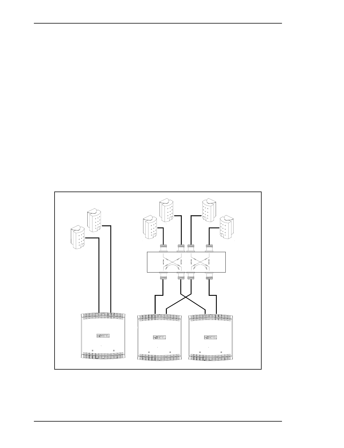
4.1 Overview
This Method includes procedures to mount and connect a Picocell 1900
antenna system. Picocell 1900 transceivers may be connected to
antennae directly or combined through hybrids to antennas. Appendix A
provides some reference information for 4 port Hybrids.
Dual 4 Port Hybrid
The Dual 4 port hybrid shown in Figure 1 is a bi-directional RF device
which combines input ports to the output ports and provides isolation
between inputs. The 4 port hybrid Insertion loss is typically 3.5 dB or
less. Connecting one antenna from each transceiver to one 4 port hybrid
input configures each RF channel on all 4 antennae. Cell partitions with
2-4 antennas use a dual 4 port Hybrid. Cell partitions with 5-8 antennas
use a dual 8 port hybrid.
Figure 1 – Single and Dual Picocell 1900 Antenna Configurations
IN 2
RF 3,4
OUT 2
RF 2RF 1 RF 1 RF 2
RF 1,2
IN 1
RF 1,2
25 dB
3.5 dB
OUT 1
RF 3 RF 4
IN 3 IN 4
RF 3,4RF 1,2
25 dB
OUT 4
OUT 3
3.5 dB
RF 1,2,3,4
RF 1,2 RF 1,2,3,4 RF 1,2,3,4
RF 1,2,3,4
Picocell 1900 Antenna System Installation / 13
September 4, 1998 Method 12-0152
Draft
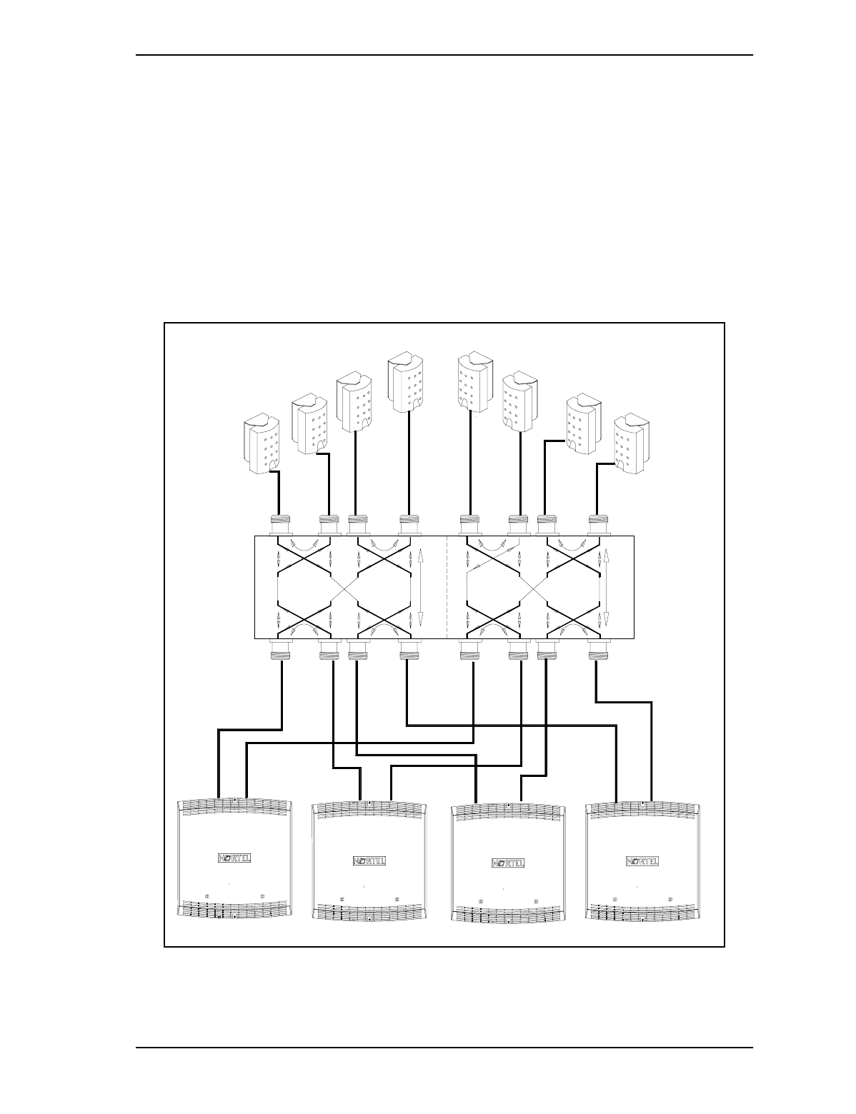
Dual 8 port Hybrid
The dual 8 port hybrid shown in Figure 2 is a multiple hybrid device,
which internally configures 4 port hybrids to connect 4 input ports to 4
output ports with isolation between input ports. Insertion loss on the 8
port hybrid is typically 7.2 dB or less. The two antennae from each
transceiver connect to an input on each 8 port hybrid and so configures
each RF channel on all antennae connected to the hybrid outputs. Low-
loss coaxial cables connect between the antennae, hybrids and
transcievers.
Figure 2 – Four unit Picocell 1900 Antenna Configuration
RF 1- 8
25 dB
25 dB
3 4 3 4 5 6
5 6
RF1 RF 2 RF 3 RF 4 RF 5 RF 6
1 2 1 2
IN 2
IN 1
25 dB
IN 4
IN 3 IN 5 IN 6 IN 7
25 dB 25 dB
25 dB
2
OUT
1
OUT
7.2dB
25 dB 25 dB
4
OUT
3
OUT 5
OUT 7
OUT
6
OUT
RF 1- 8
RF 1- 8
RF 1- 8
RF 1- 8
RF 1- 8
RF 1- 8
7 8 7 8
RF 7 RF 8
IN 8
7.2B
8
OUT
RF 1- 8
14 / Picocell 1900 Antenna System Installation
Method 12-0152 September 4, 1998
Draft
5.0 Mounting the Hybrid(s)
Hybrids may be mounted on bare wall surfaces; transceivers must
follow mounting guidlines listed in IM 02-0245. Typical back board
mounting is illustrated in Figures 5 and 6. Hybrids are passive devices
and may be mounted in enclosed spaces; leave room for cabling and test
access. Ceiling mounting of hybrids should include custom brackets
with nut and bolt fasteners with IDS clips (see IM 02-0245) to support
the hybrid and cables. Supporting hybrids on ceilings with common dry
wall anchors is not recommended. The hybrid requires a mounting kit
consisting of:
- 2.5" x # 10 wood screws
- washers 1/2" outside diameter
- a hole drilling template
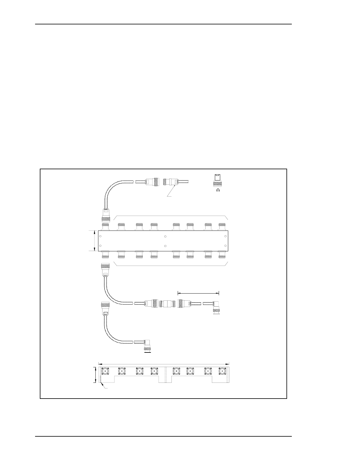
Figure 3 – Dual 8 Port Hybrid (CPC A0737243))
Note: The Hybrid(s) should be mounted to permit the RF cables to enter
and leave with out excessive bending and stress on connectors.
To
Picocell
Antenna
Port
IN 2
OUT 2
IN 1
OUT 1 OUT 7
IN 6
IN 4
IN 3 IN 5 IN 8
IN 7
OUT 3 OUT 4 OUT 5 OUT 6 OUT 8
Antennae
To
for Type
See Table 1 & 2
for Type
See Table 1 & 2
15.5"
.231" hole X 6
1.8 m Jumper
1.75" 1.68"
To
Unit 1
Picocell
Antenna 1
Cabling if radio/hybrid spacing > 6'
Cabling if radio/hybrid spacing < 6'
To
Unit 1
Picocell
Antenna 1
A0737243 Dual 8 Port Hybrid
B0241275
A0600384
B0241275
'TNC' (m)
Adapter
'N' (m)
1.8 m Jumper
'N' (m)
N-N
'TNC' (m)
To
'N' (m)
P/O Antenna
Ass'y
Antenna
Termination on
unused ports
50
A0609689
Picocell 1900 Antenna System Installation / 15
September 4, 1998 Method 12-0152
Draft
Procedure 1 – Mounting the Hybrid:
1. Choose a location for the Hybrid(s) so cabling to Picocell 1900 units and
antennas will form neatly off. Use the drilling template to mark the
screw holes. Predrill the holes if necessary. Screw the Hybrid(s) to the
mounting board.
2. Terminate unused output ports with 50 Ohm 1Watt Terminations
(Andrew part # 50T-007, NT part # A0609689).
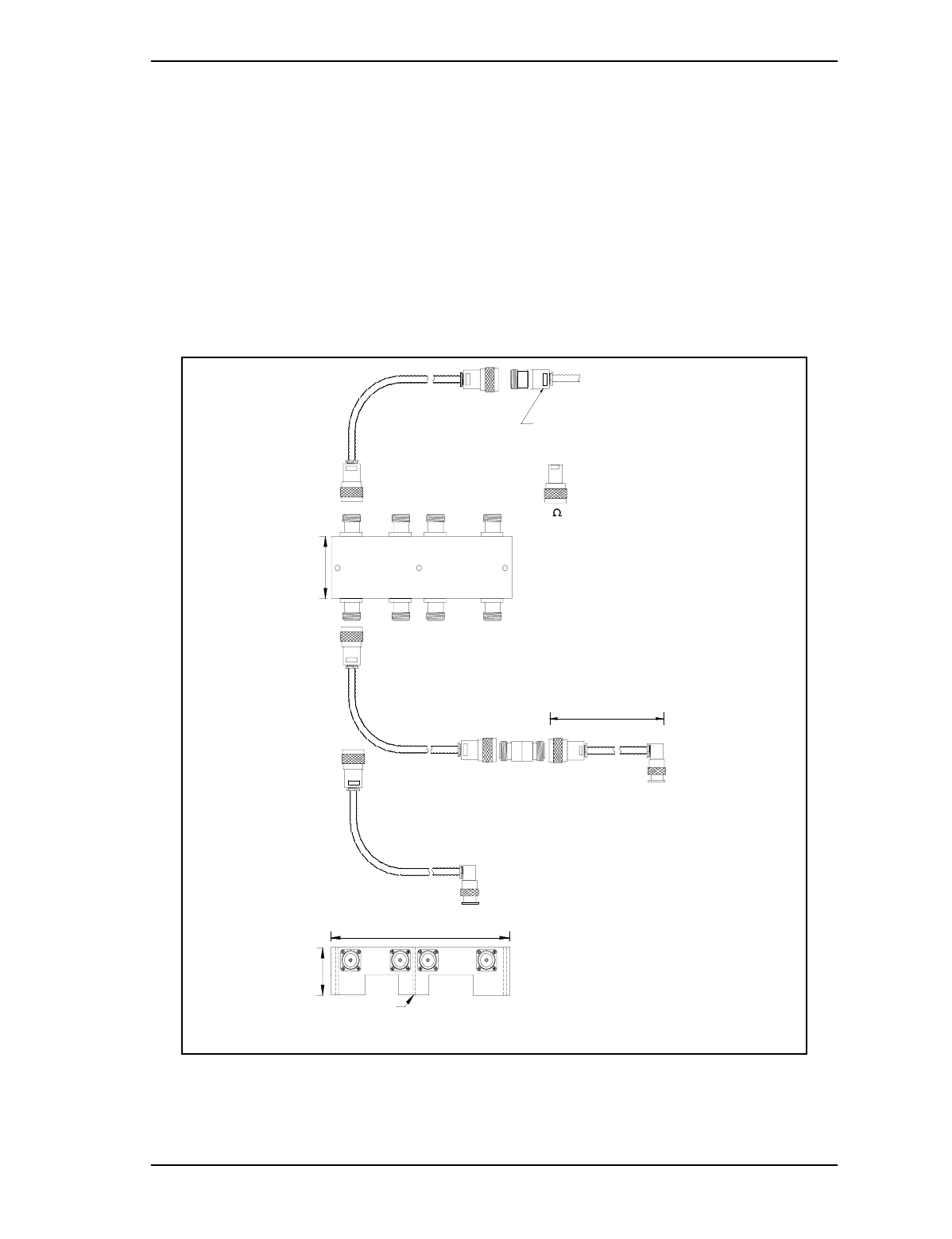
Figure 4 – Dual 4 Port Hybrid (CPC A0735611)
1.8 m Jumper
Cabling if radio/hybrid spacing > 6'
Cabling if radio/hybrid spacing < 6'
B0241275
To
Unit 1
Picocell
Antenna 1
1.75"
6.59"
.231" x 3
A0735611 Dual 4 Port Hybrid
A0600384
B0241275
'TNC' (m)
1.8 m Jumper
To
Unit 2
Picocell
Antenna 2
To
Unit 1
Picocell
Antenna 2
To
Unit 2
Picocell
Antenna 1
for Type
See Table 1 & 2
'N' (m)
Adapter
'N' (m) N-N
IN 1
OUT 1
IN 2 IN 4
OUT 2 OUT 4
IN 3
OUT 3 Termination on
unused ports
A0609689
2.0"
To To To
Antenna Antenna Antenna 50
for Type
See Table 1 & 2 Antenna
P/O Antenna Ass'y
'N' (m)
To
To
Unit 1
Picocell
Antenna 1
'TNC' (m)
16 / Picocell 1900 Antenna System Installation
Method 12-0152 September 4, 1998
Draft
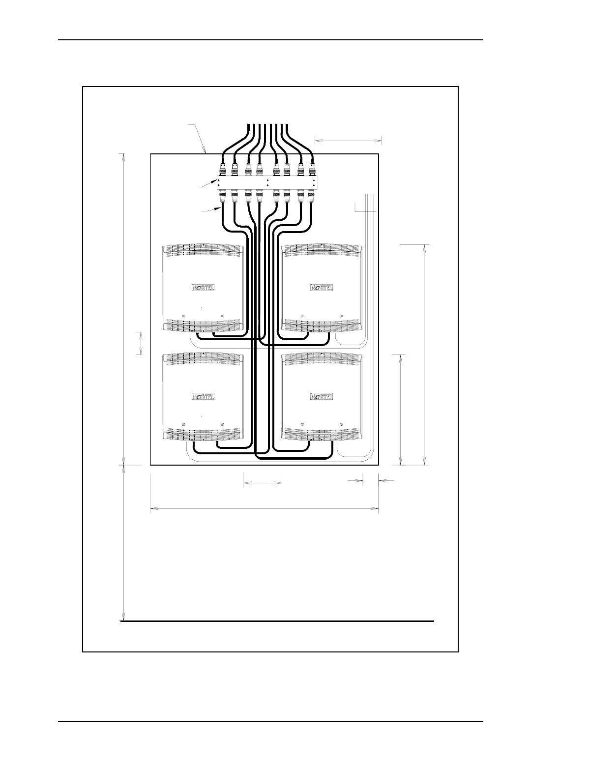
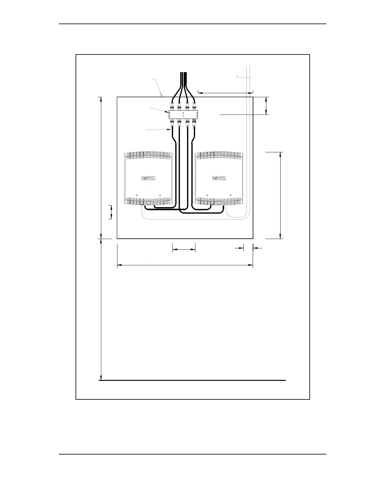
Figure 5 – Dual 8 port Back board Mounting (Typical)
48.00"
34.00"
17.00"
36.00"
Dimensions subject to site requirements.
24.00"
Floor Level
2.50"
6.00"
To Remote Antennas
OUT 2
IN 2
B0241275
N-TNC 1.8M
x8
3.50"
3/4" x 4' x 3' min.
Plywood G1S FIR
A0737243
Dual 8 port Hybrid
OUT 1
IN 1
10.50"
OUT 6
IN 6
OUT 5OUT 4
OUT 3
IN 5IN 3 IN 4
OUT 8
IN 7 IN 8
OUT 7
PWR
TCM/
Picocell 1900 Antenna System Installation / 17
September 4, 1998 Method 12-0152
Draft
Figure 6 – Dual 4 port Back board Mounting (Typical)
36.0"
22.0"
36.0"
6.0"
Dimensions subject to site requirements.
36.0"
Floor Level
2.5"
To Remote Antennas
OUT 3
IN 3
B0241275
N-TNC 1.8M
x4
3.5"
3/4" x 4' x 3' min.
Plywood G1S FIR
A0735611
Dual 4 port Hybrid
OUT 1
IN 1
OUT 2
IN 2
4.5"
14.5"
OUT 4
IN 4
TCM
18 / Picocell 1900 Antenna System Installation
Method 12-0152 September 4, 1998
Draft
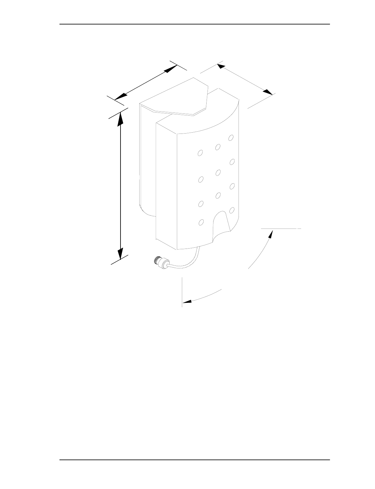
6.0 Picocell 1900 Antennas
Two antennas types are supported in this document which may be
provided in the system design. the The directional antenna must be
mounted vertically on the wall and may swivel over a +/- 30 degree
range, with the front of the antenna facing in the direction of RF
propogation.
The Omni antenna is only mounted on ceilings and weighs .52 lb (.23kg)
and does not require any extra support. The wall mount Directional
antenna weighs .5 lb as well. Refer to the floor plan for tolerances on
deviating from the ideal position should it not be possible to mount in
the specified position due to obstructions.
Antenna Mounting hardware kit
- 1" x #10 wood screws
- Drywall anchors
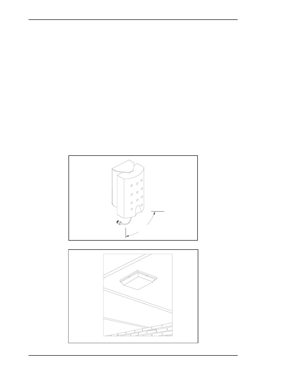
Figure 7 – Directional (Cushcraft part number: S1857AMP10NF, CPC: A0736188
Figure 8 – Omni Antenna (Cushcraft part number: SQ1853P12NF, CPC: A0735776
60.0°
Swivel
Picocell 1900 Antenna System Installation / 19
September 4, 1998 Method 12-0152
Draft
Procedure 2 – Ceiling Mount Omni Antennas
1. Mark out the location of the antenna on the ceiling, and the direction it
is supposed to face. Check to see if there are any obstructions. Make
adjustments if necessary but stay within the tolerances stated on the
floor plan.
2. Use the mounting flange on the antenna to mark the screw holes on the
ceiling. Predrill the holes, and place the drywall anchors.
3. Connect the antenna to the transmission line and then screw the antenna
in place, see Figure 9.
Note: For surfaces that will not accept wood screws (such as concrete,
brick and steel), you must select and supply the appropriate
hardware yourself.
Figure 9 – Omni Antenna Ceiling Mounting
Omni
Antenna
A0735776
6"
Mounting screws
x 4
Dry Wall
Anchors x 4
1"
6"
20 / Picocell 1900 Antenna System Installation
Method 12-0152 September 4, 1998
Draft
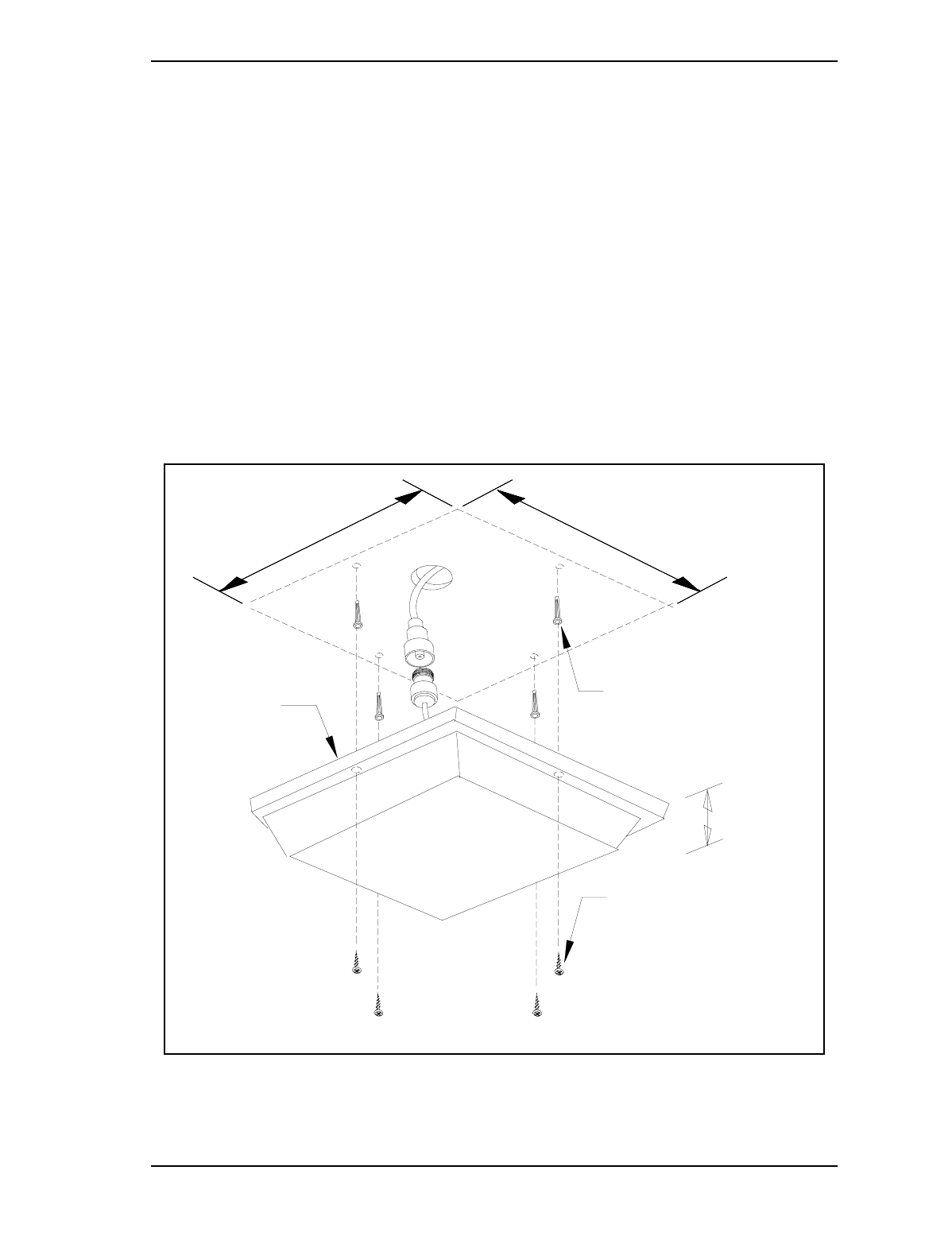
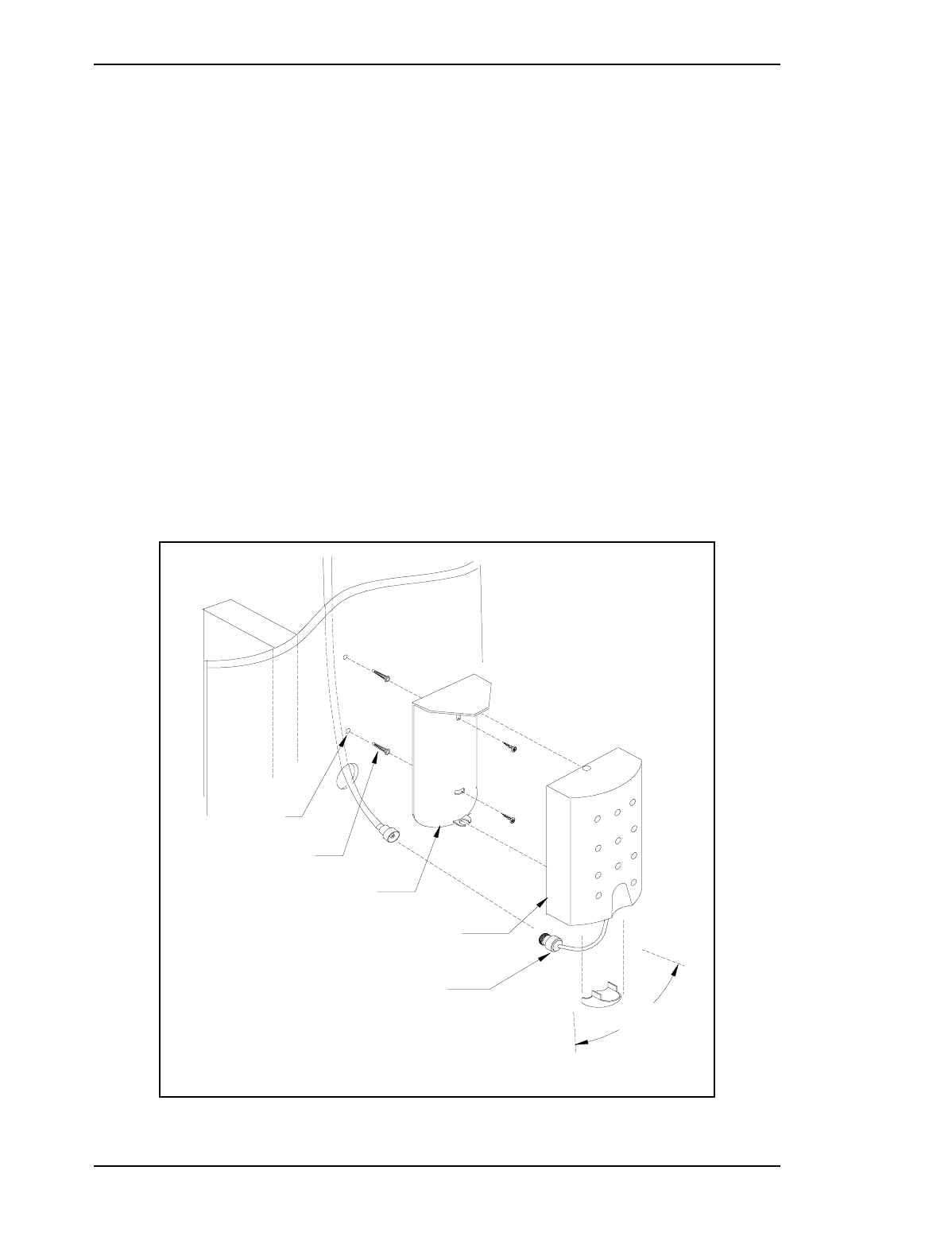
Procedure 3 – Mounting Directional Antenna and Wall Bracket
1. Approximately position the antenna and bracket. Use the bracket or
template provided with the antenna to mark and drill pilot holes for the
wall anchors. See Figure 10.
2. Drill the Cable access hole if required.
3. Use the two screw holes on the mounting brackets back plate to mark
the screw holes on the wall. screw the antenna bracket in place. Position
the antenna just above the access hole
4. The cable may be run down the outside wall surface from the ceiling .
For installations in buildings with hollow walls, the cable may be passed
through the cable hole in the mounting bracket through the wall and then
up into the ceiling cavity.
Note: For surfaces that will not accept wood screws (such as concrete,
brick and steel), you must select and supply the appropriate hardware
yourself.
Figure 10 – Directional Antenna Wall Mounting
Wall Mount Bracket
+/- 30 degree Swivel
.48mm
pilot hole
60.0°
Swivel
Dry Wall
Anchors x 2
120 degree Directional
Antenna
A0736188
'N' Female
Connector
Picocell 1900 Antenna System Installation / 21
September 4, 1998 Method 12-0152
Draft
Figure 11 – Directional Antenna dimensions
60.0°
Swivel
3.8"
5.8"
2.26"

22 / Picocell 1900 Antenna System Installation
Method 12-0152 September 4, 1998
Draft
7.0 Cable Types and Connectors
Andrew cables and connectors are recommended for use throughout the
Picocell 1900 antenna system. One exception is the Huber-Suhner
Jumper at the Picocell 1900 transceiver. The tables below lists
recommended connector and cable types. The Andrew Corporation
connector catalog numbers, Nortel CPC part number, manufacturer and
insertion loss is listed below. Circumstances may result in equivalent
cable types being specified or sourced from other manufacturers. Use
the original Equipment Manufacturer’s (OEM) instructions supplied
with the connectors for assembly.
The N(m) to TNC(m) jumper connects the main transmission line to the
Picocell 1900 transceiver which requires a flexible cable for entry.
Table 4 – Andrew Cable Types and Insertion Loss
Cable Description CPC Manufacturer Lossa (dB/
100m)
a. AT 2 GHz, VSWR 1.0, ambient temperature 24°C. Losses does not include Connector Losses
0.25″ Foam Superflex: FSJ1-50A R0116633 Andrew 28.6
0.25″ Plenum, Foam Superflex: ETS1-50T R0116910 Andrew 28.0
0.375″ Foam: LDF2-50 R0116726 Andrew 17.1
0.5″ Foam: LDF4-50A R0116728 Andrew 11.3
0.5″ Foam Superflex: FSJ4-50B R0116634 Andrew 17.7
0.5″ Plenum, Foam: FT4-50T R0116883 Andrew 20.3
RF Antenna Cable (TNC male to N-Male)
(This is a Jumper cable 1.8 m long and
1.5 dB attenuation)
B0241275 Huber Suhner 75.0

Picocell 1900 Antenna System Installation / 23
September 4, 1998 Method 12-0152
Draft
Table 5 – Andrew Connectors
7.1 RF Cable Installation
RF cables should normally be placed in conduit or cable trays. Where
this is not possible the Heliax cable should be supported every 24 ". The
Systems Engineer must determine if cabling meets Fire Regulations and
Building codes. Notify the System Engineer of deviations in cable
routing from the System design document .
Table 6 –Heliax Minimum Bending Radius
Connector Description CPC Manufacturer For Use with Comments
0.25″ N-Male: 41PW A0382258 Andrew 0.25″ Coax
0.375″ N-Male: L42PW A0621669 Andrew 0.375″ Coax Use with LDF cables
0.375″ N-Male: 42SPW A0621669 Andrew 0.375″ Coax Use with Superflex
cables
0.5″ N-Male: L44PW A0615483 Andrew 0.5″ Coax Use with LDF cables
0.5″ N-Male: 44SEW A0381727 Andrew 0.5″ Coax Use with Superflex
cables
50W termination, Male:
50T-007 A0609689 JFW Hybrids Terminating unused
ports of the hybrids
Adapter N-Female to
N- Female A0600384 Andrew Connecting Jumper to
Co-ax cable
Cable Nominal
diameter Diameter
over jacket
Minimum
bending
radius
FSJ1-50A 1/4" .29" 1"
ETS1-50T 1/4" .29" 1"
LDF2-50 3/8" .44" 3.75"
ETS2-50T 3/8" .415" 1"
FSJ4-50B 1/2" .52" 1.25"
LDF4-50A 1/2" .63" 5"
FT4-50T 1/2" .60" 5"

24 / Picocell 1900 Antenna System Installation
Method 12-0152 September 4, 1998
Draft
Procedure 4 – Placement of RF Cable
1. Inspect the cable for possible damage and verify the cable type being
placed with the system layout. Also verify that the cable type being used
meets the requirements for insertion loss as specified in the layout. See
Table 4. Maximum lengths and insertion Losses should be detailed on
the System layout or floor plan.
Note: Use of a cable reel stand is recommended to minimize stress when
placing the cable. Maintain the cable bending radius outside the
minimum values listed in Table 6 on page 23.
2. Place the cable as directed in the System Layout.
Note: When placing the RF cable equipped with connectors, use
protective plugs to prevent connector damage. It may be
impossible to run the cable equipped with the connector. In this
case run the cable to the antenna, leave slack to attach the
connector.
3. Run the cable through the ceiling access hole at the antenna location and
attach the connector to the antenna See "Picocell 1900 Antennas" on
page 18 .
4. Cut the cable to the desired length.
Note: Allow enough length at each end to terminate the connector and
allow the cable to be neatly formed to the Antenna or Hybrid.
Coiling back excess cable is not recommended in order to
minimize cable insertion loss.
5. Attach connectors and label the end of the cable according to the
designation it has been given in the connectivity chart.
6. Attach the connector to the appropriate output port on the Hybrid, and
secure the cable to the mounting wall. The cables should be neatly
formed and secured.
Caution: Do not apply excessive force to cable ties to avoid deforming
or denting the cable shield. Heliax cable damaged with dents or bending
tighter than the minimum bending radius will degrade performance.
Damaged cables should be replaced.
Picocell 1900 Antenna System Installation / 25
September 4, 1998 Method 12-0152
Draft
7.2 RF Cable Connector Assembly
The instructions listed in this procedure are typical, based on standard
Andrew parts listed here and may be used where suppliers instructions
are not available. Andrew connectors are normally supplied with
assembly instructions.
Table 7 –Connector Torque Specifications
The instructions supplied by Andrew shall supersede the
information listed in this document unless specified otherwise.
Some cable types may require special Andrew tools, refer to
the original instructions supplied with the connector for their
use.
Cable description Cable # Connector Required torque
1/4" Heliax superflexible standard jacket FSJ1-50A F1PNM-HF
(41PW) 48 in/lb
1/4" Heliax superflexible plenum ETS1-50T F1PNM-HF
(41PW) 48 in/lb
3/8" Heliax foam dielectric standard
jacket L D F2 - 5 0 L 2 P NM
(L42PW) 48 in/lb
3/8" Heliax foam dielectric superflexible,
plenum ETS2-50T F2PNM
(42SPW) 96 - 144 in/lb
1/2" Heliax superflexible standard jacket FSJ4-50B F4PNM
(44SEW) 96 - 144 in/lb
1/2" Heliax foam dielectric standard
jacket LDF4-50A L4PNM
(L44PW) 142 -146 in/lb
1/2" Heliax foam dielectric plenum FT4-50T L4PNM
(L44PW) 142 -146 in/lb

26 / Picocell 1900 Antenna System Installation
Method 12-0152 September 4, 1998
Draft
Procedure 5 – Preparing the Heliax cable:
1. Straighten at least 10" of the working end of the cable. Trim 1" off this
end of the cable with the fine tooth hacksaw to provide a fresh working
edge.
Note: Crimping the cable, even slightly, is not acceptable.
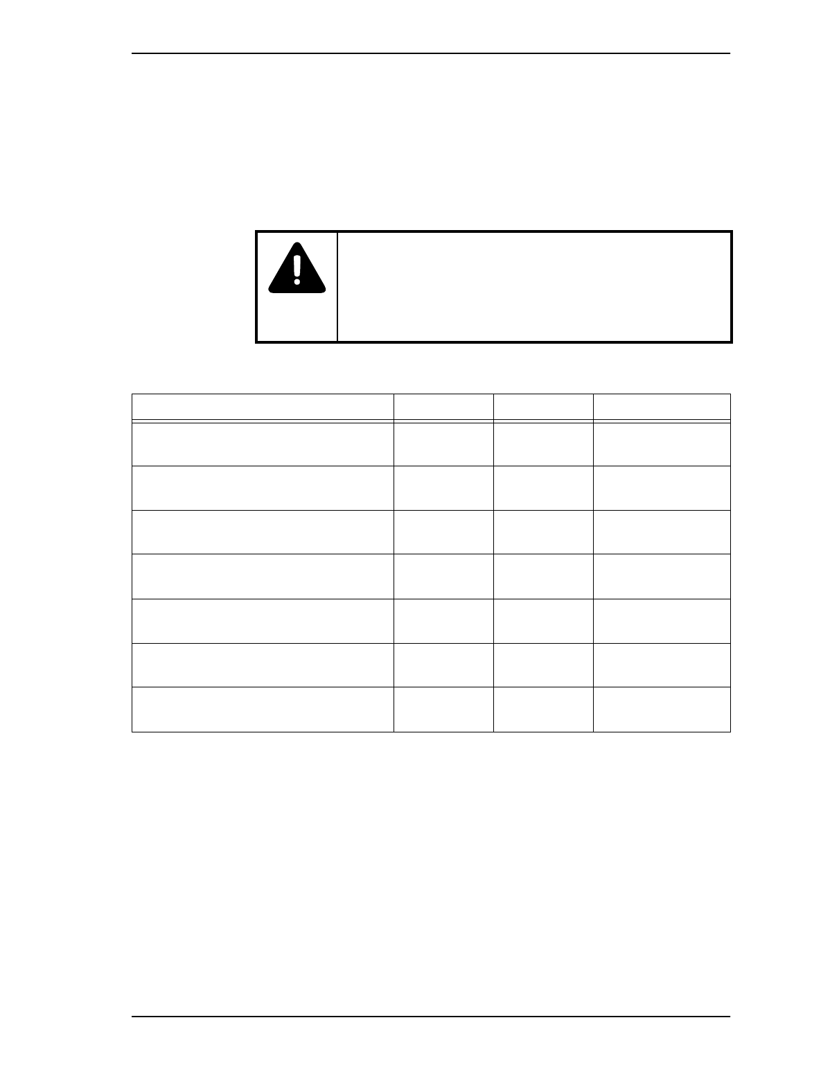
2. Use a sharp knife and remove some of the jacket to expose the outer
conductor. See Figure 12 for the amount of jacket to be removed. Avoid
cutting the outer conductor. Remove any burrs on the outside edge of
the outer conductor and clean with solvent.
3. Lightly grease the O ring/gasket and the inner surface of the clamping
nut with silicone. Be careful to apply the silicone only to the desired
areas.
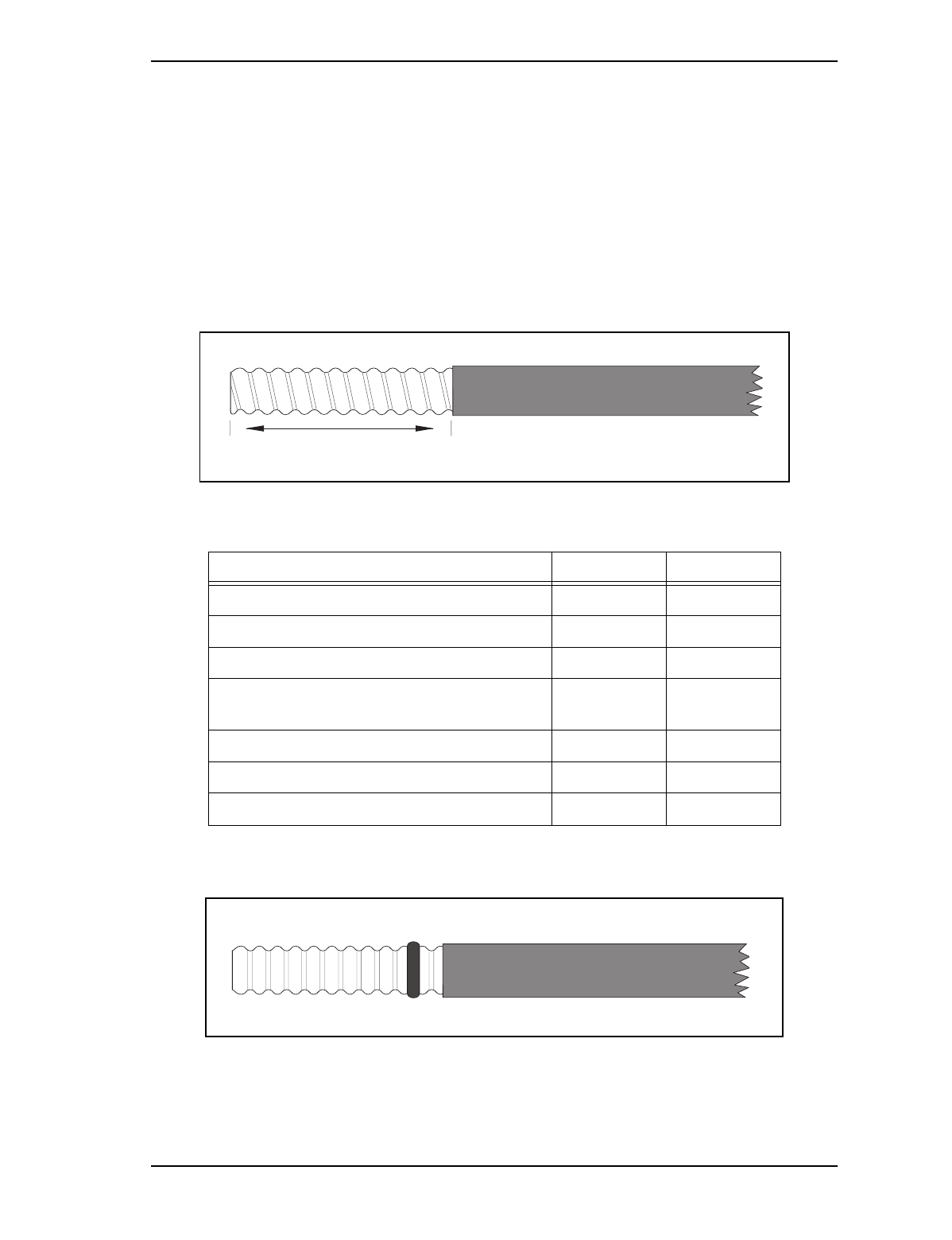
Note: When putting the gasket on, slide the smooth end of the gasket
over the conductor first, being careful not to rip it on the conductor
and ensure it is fitted evenly on the conductor.
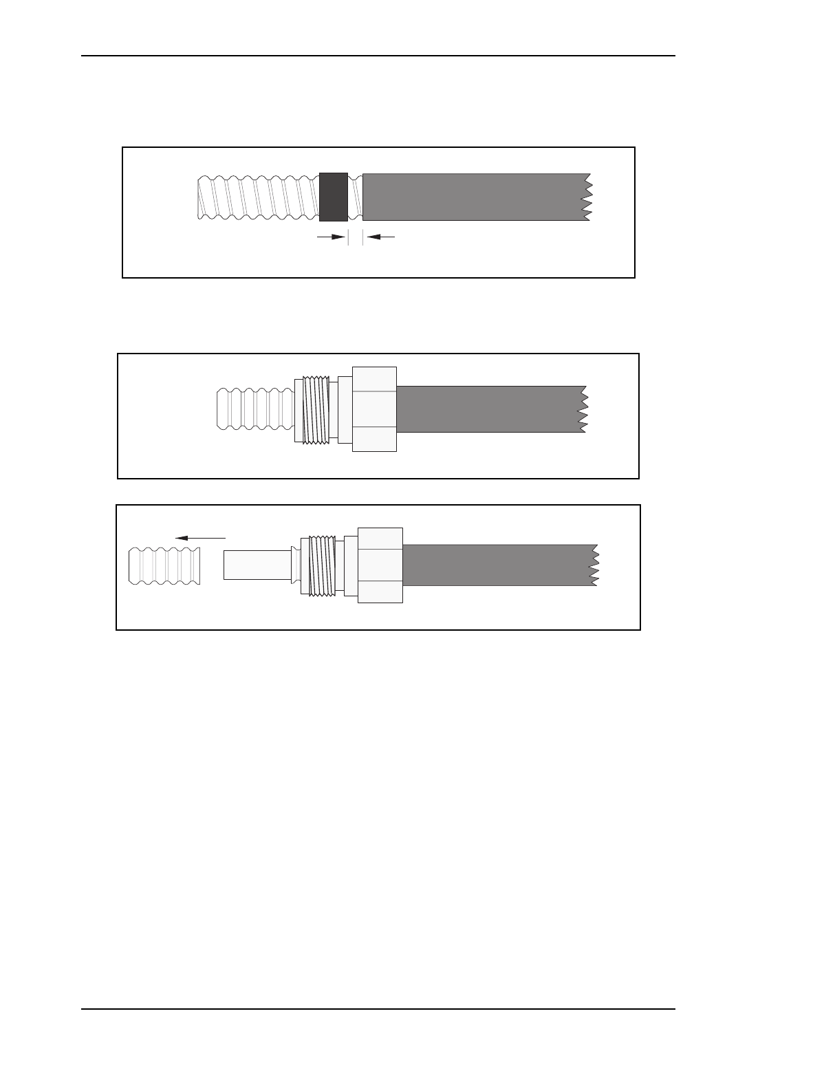
4. Screw on the clamping nut: Hand thread the clamping nut onto the outer
conductor, then use a wrench to tighten it into place.
5. Trim the outer conductor so that only the desired amount is left showing
(see Table 5). Use a hacksaw or jewelers saw to cut through the outer
conductor. Use a guide to ensure a straight cut, because it is important
that the cut be parallel to the edge of the clamping nut. Pull the excess
off with a pair of pliers.
6. Cut the inner conductor: Use a hacksaw or jewelers saw to cut the inner
conductor to the desired length (see Table 5). Deburr the cut end with a
file.
Note: Hack-saw blades coated with paint are not to be used to avoid
contaminating the conductor surface with paint impurities.
7. Clean the foam: Use a small brush to clean all the dirt and metallic
particles off the foam. The particles and dirt interfere with the signal
traveling through the cable.
8. Separate foam from the outer conductor: (This is not necessary in the 1/
4" cable/connector assemblies) Gently separate the foam from the outer
conductor. Insert the tip of a knife between the foam and the outer
conductor to a depth of 1/16" and separate them so that the outer
conductor can be flared. Scrape away any foam clinging to the outer
conductor and remove any burrs from the inside edge. Use a small brush
to clean the foam again, if necessary.
9. Flare the outer conductor: The 1/4" cable/connector assemblies, FSJ1-
50A/41PW and ETS1-50T/41PW, require the outer conductor to be
Picocell 1900 Antenna System Installation / 27
September 4, 1998 Method 12-0152
Draft
manually flared against the clamping nut. Proceed to Paragraphs 9g and
9h for flaring the 3/8" and 1/2" cable/connector assemblies.
10. Clean the foam off the inner conductor with a knife. Be careful not to
scrape the inner conductor. Use the garnet cloth to remove the adhesive
and to ensure that the surface is clean.
Note: The surface must be residue free, leftover foam can interfere with
setting the pin on the conductor and can reduce conductivity.
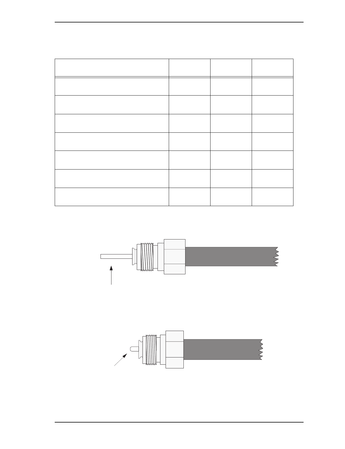
Figure 12 – Outer Sheath Stripping Lengths
Table 8 –Outer Seath Strip Length
.
Figure 13 – . Cable With O Ring
Cable description Cable # Distance
1/4" Heliax superflexible standard jacket FSJ1-50A 7/8"
1/4" Heliax superflexible plenum ETS1-50T 7/8"
3/8" Heliax foam dielectric standard jacket LDF2-50 1 1/4"
3/8" Heliax foam dielectric superflexible, ple-
num ETS2-50T 1 1/2"
1/2" Heliax superflexible standard jacket FSJ4-50B 1 1/2"
1/2" Heliax foam dielectric standard jacket LDF4-50A 2"
1/2" Heliax foam dielectric plenum FT4-50T 2"
amount of jacket to be removed
28 / Picocell 1900 Antenna System Installation
Method 12-0152 September 4, 1998
Draft
Figure 14 – Cable With Gasket
Put the gasket on the conductor about 1/16 of an inch from the jacket.
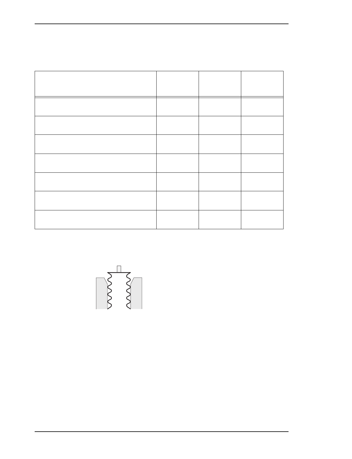
Figure 15 – Clamping Nut
Figure 16 – Trim Outer Conductor
1/16"
Picocell 1900 Antenna System Installation / 29
September 4, 1998 Method 12-0152
Draft
Table 9 – Outer Conductor Trim Lengths
Figure 17 – Center Conductor Finishing
Figure 18 – Size The Inner Conductor
Cable description Cable # Connector Amount
showing
1/4" Heliax superflexible standard jacket FSJ1-50A F1PNM-HF
(41PW) 1/16"
1/4" Heliax superflexible plenum ETS1-50T F1PNM-HF
(41PW) 1/16"
3/8" Heliax foam dielectric standard jacket LDF2-50 L2PNM
(L42PW) flush
3/8" Heliax foam dielectric superflexible,
plenum ETS2-50T F2PNM
(42SPW) 1/32"
1/2" Heliax superflexible standard jacket FSJ4-50B F4PNM
(44SEW) 1/16"
1/2" Heliax foam dielectric standard jacket LDF4-50A L4PNM
(L44PW) flush
1/2" Heliax foam dielectric plenum FT4-50T L4PNM
(L44PW) flush
inner conductor – make sure it is clean
deburr the end
30 / Picocell 1900 Antenna System Installation
Method 12-0152 September 4, 1998
Draft
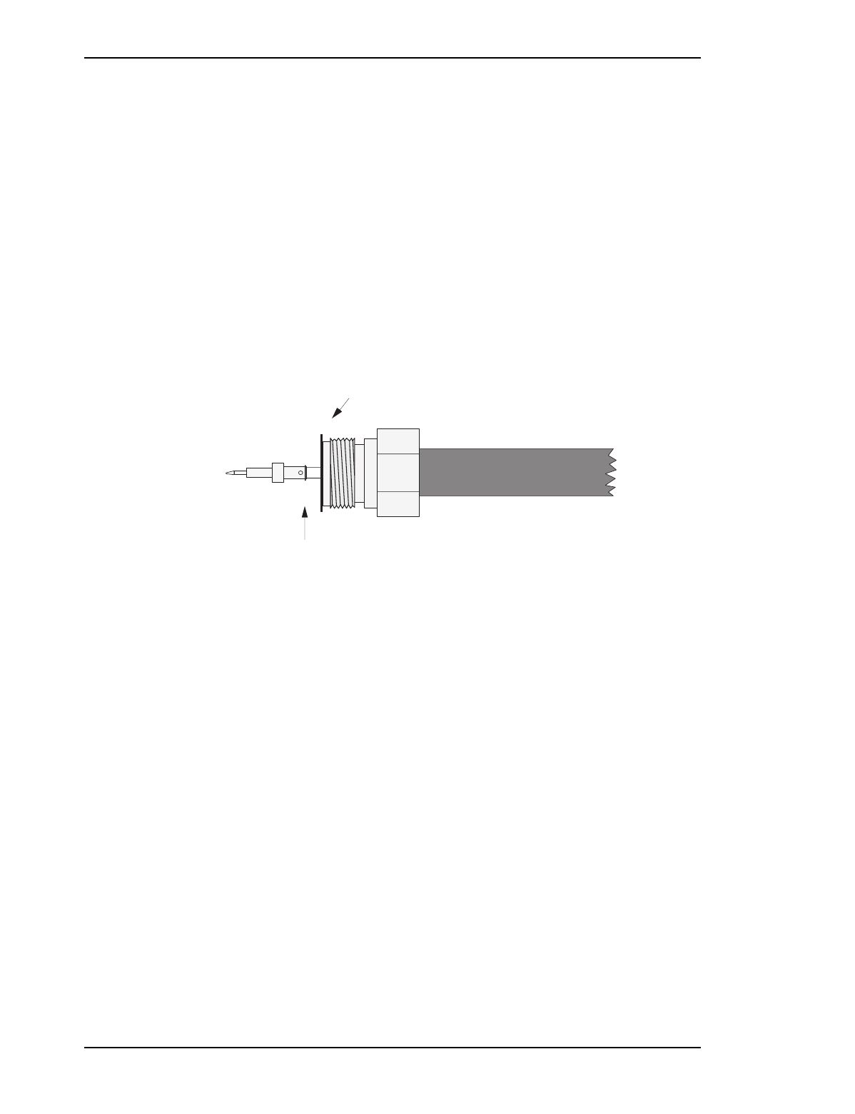
Table 10 –Center Conductor Trim Length
Figure 19 – Cable/Clamping Nut
Cable description Cable # Connector Inner
conductor
length
1/4" Heliax superflexible standard jacket FSJ1-50A F1PNM-HF
(41PW) 1/4"
1/4" Heliax superflexible plenum ETS1-50T F1PNM-HF
(41PW) 1/4"
3/8" Heliax foam dielectric standard jacket LDF2-50 L2PNM
(L42PW) 3/16"
3/8" Heliax foam dielectric superflexible, ple-
num ETS2-50T F2PNM
(42SPW) 7/32"
1/2" Heliax superflexible standard jacket FSJ4-50B F4PNM
(44SEW) 3/16"
1/2" Heliax foam dielectric standard jacket LDF4-50A L4PNM
(L44PW) 7/32"
1/2" Heliax foam dielectric plenum FT4-50T L4PNM
(L44PW) 7/32"
cross-section of the cable and
clamping nut

Picocell 1900 Antenna System Installation / 31
September 4, 1998 Method 12-0152
Draft
Procedure 6 – Flaring 3/8" and 1/2" cable/connector assemblies:
1. The 3/8" and the 1/2" cable/connector assemblies, LDF2-50/L42PW,
ETS2-50T/42SPW, FSJ4-50B/44SEW, LDF4-50A/L44PW, FT4-50T/
L44PW, are designed to be self-flaring:
2. Slip the outer body of the connector over the clamping nut, and tighten
to the appropriate torque using a set of wrenches; see Table 6 for the
appropriate torques. The flaring surface of the outer body will flatten
the outer conductor against the clamping nut.
3. Disassemble the connection and inspect the flare to ensure that there is
good metal to metal contact. If it is not correctly flared, repeat the
procedure.
32 / Picocell 1900 Antenna System Installation
Method 12-0152 September 4, 1998
Draft
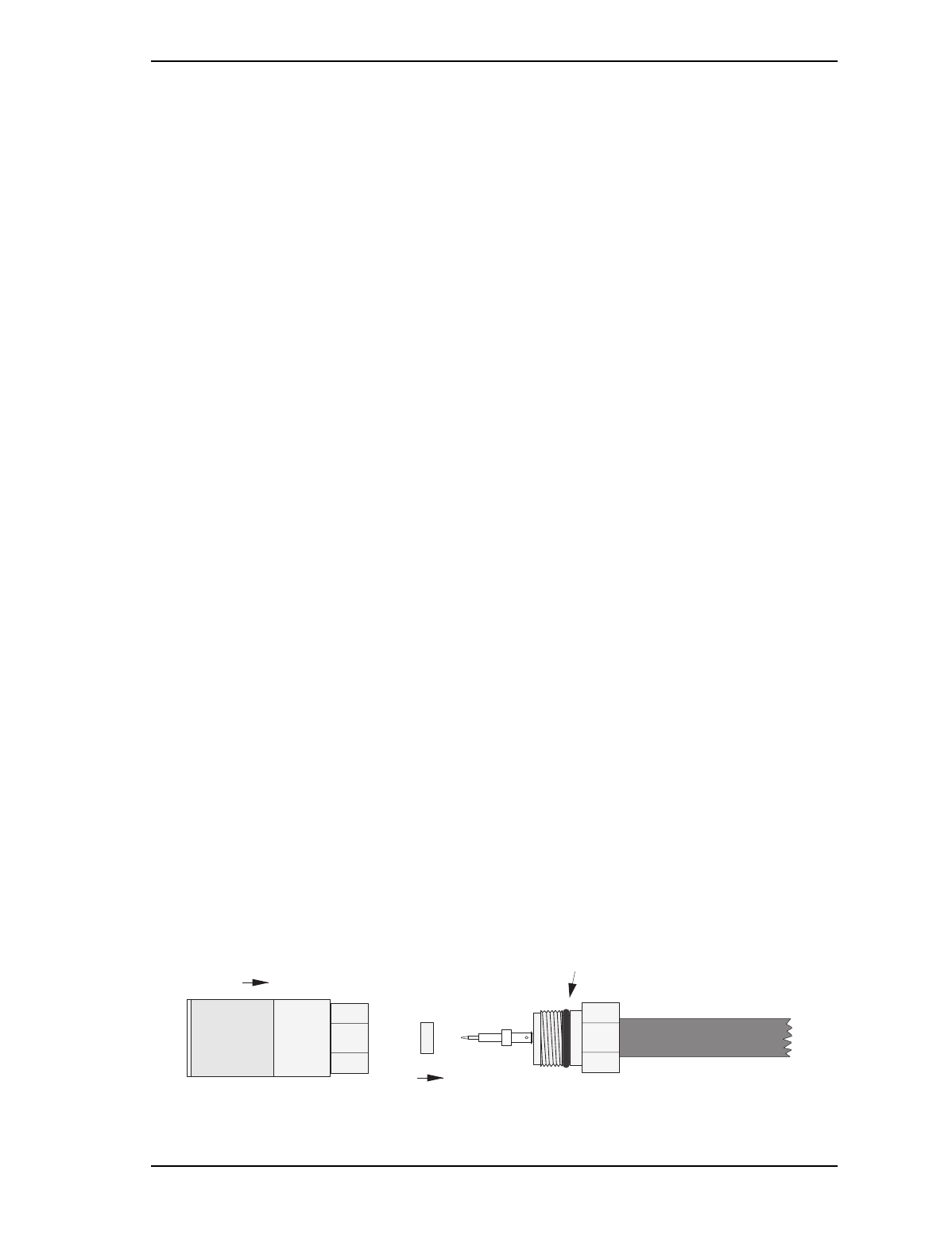
Procedure 7 – Center Conductor Finishing
1. The connector assembly kit comes with a thin spacing plate which is
used to set the distance between the pin and the outer conductor. It also
shields the dielectric foam from excess heat. Before soldering the pin to
the inner conductor, place the spacing gauge over the inner connector
against the outer conductor/clamping nut.
2. Cut a piece of solder equal in length to the inner hole of the pin and place
in the pin. Place the pin against the end of the inner conductor and apply
the soldering iron at the same time applying slight pressure on the pin.
Figure 20 – Assembling the center pin and center conductor.
3. Heat the pin with the soldering iron; as the pin heats up, it will melt the
solder. The pin will then slide over the inner conductor. Hold for a
second longer to ensure and even flow of solder to avoid a cold solder
joint from occuring.
Note: By first placing solder in the pin a good solder flow is ensured and
solder wetting on the pin surface is minimized as is accidentally
melting the foam dielectric. It is important to push the pin on as
far as it can go. Any excess solder will seep out through the hole
on the side of the pin. This is a good indication that solder flowed
evenly between the pin and center conductor.
4. Remove any excess solder from the center pin with a fine file. Clean
filings off thourghly before final assembly.
Note: Avoid scratching the pin when trimming off the excess solder and ensure
that the pin is aligned with the axis of the cable.
spacing plate tight up against
flared outer conductor
pin (with piece of solder inside)
pushed against inner conductor
Picocell 1900 Antenna System Installation / 33
September 4, 1998 Method 12-0152
Draft
Procedure 8 – Assembling the Connector Body
1. Slide the second O ring onto the groove on the clamping nut and apply
a thin coat of silicone grease. Keep all connector threads free of grease.
Attach the outer body (and flare ring if necessary):
Note: The 1/4" connectors have a flare ring that must be inserted into the
outer body before it is threaded onto the clamping nut.
2. Thread the outer body onto the clamping nut and tighten the connection
with wrenches, see Figure 23. Do not turn the clamping nut to tighten,
turn only the outer body until secure. To ensure a proper connection use
a torque wrench and tighten to the required torque, see Table 6.
3. you will have difficulty putting the outer body on the clamping nut if the
pin is askew. Straighten the pin out slightly and the outer body should
go into place.
4. Check pin alignment to verify the center pin is centered. If it is not,
slide the pin alignment tool over the pin and center it.
5. Check pin depth with the depth gauge to check the setting of the pin.
The gauge shows whether the contact pin is positioned within tolerance.
The gauge is pushed onto the pin assembly and a plunger rises to
indicate if the pin is installed between the upper and lower tolerance
limits. If the pin depth is outside of the tolerances, take off the outer
body and check the pin.
Note: If the pin exceeds the upper tolerance limit, reheat the solder and make sure the
pin is pushed all the way on. If this is not the source of the problem, check the
length of the inner conductor. If the inner conductor is too long, recut the inner
conductor. Re-solder the pin on and repeat procedure 7 and 8.
Note: If the pin is below the lower tolerance level, the length of the inner conductor
has been cut too short. Tightening the clamping nut might correct this situation
if the inner conductor has not been cut too short. If it has been cut too short,
you will have to start the assembly process over again.
6. Slide the black heat-shrink over the connector and cable; use the heat
gun to shrink it in place. Be careful not to melt the heatshrink or the
jacket.
Figure 21 – Final Assembly
put O ring in groove
slide flare ring over pin
attach outer body

34 / Picocell 1900 Antenna System Installation
Method 12-0152 September 4, 1998
Draft
7.3 References
Document Number Title
IM 04-0241 Picocell 1900 CSI Installation and Planning
IM 04-0242 Picocell 1900 General Information and Plannng
IM 08-0243 Picocell 1900 CSI Equipment Handling and
Securing
IM 04-0244 Picocell 1900 System Cabling and Cross Connect
IM 12-0152 Picocell 1900 Antenna System Installation
IM 02-0245 Picocell 1900 transceiver Installation
IM 12-0152 PICOCELL 1900 Antenna System Installation
IM 22-0246 Picocell 1900 Radio and CSI Power up
IM 24-0247 Picocell 1900 Equipment Loading and Diagnos-
tics
IM 28-0248 Picocell 1900 Radio Commissioning with the IFR
1900
IM 28-0249 Picocell 1900 System Test
Andrew
Bulletin 237161 Connector attachment for Heliax FSJ2-50 Coaxial
Cable
Andrew
Bulletin 237269 Connector attachment for Heliax FSJ4-50B Coax-
ial Cable
Andrew
Bulletin 37383D Connector attachment for Heliax LDF-50A coaxial
Cable
Andrew
Bulletin 37439B Connectors for Heliax FSJ1-50A Superflexible
Coaxial Cable
Andrew
Bulletin 37572A Connectors for Heliax LDF2-50 Foam-dielectic
Coaxial Cable
Picocell 1900 Antenna System Installation / 35
September 4, 1998 Method 12-0152
Draft
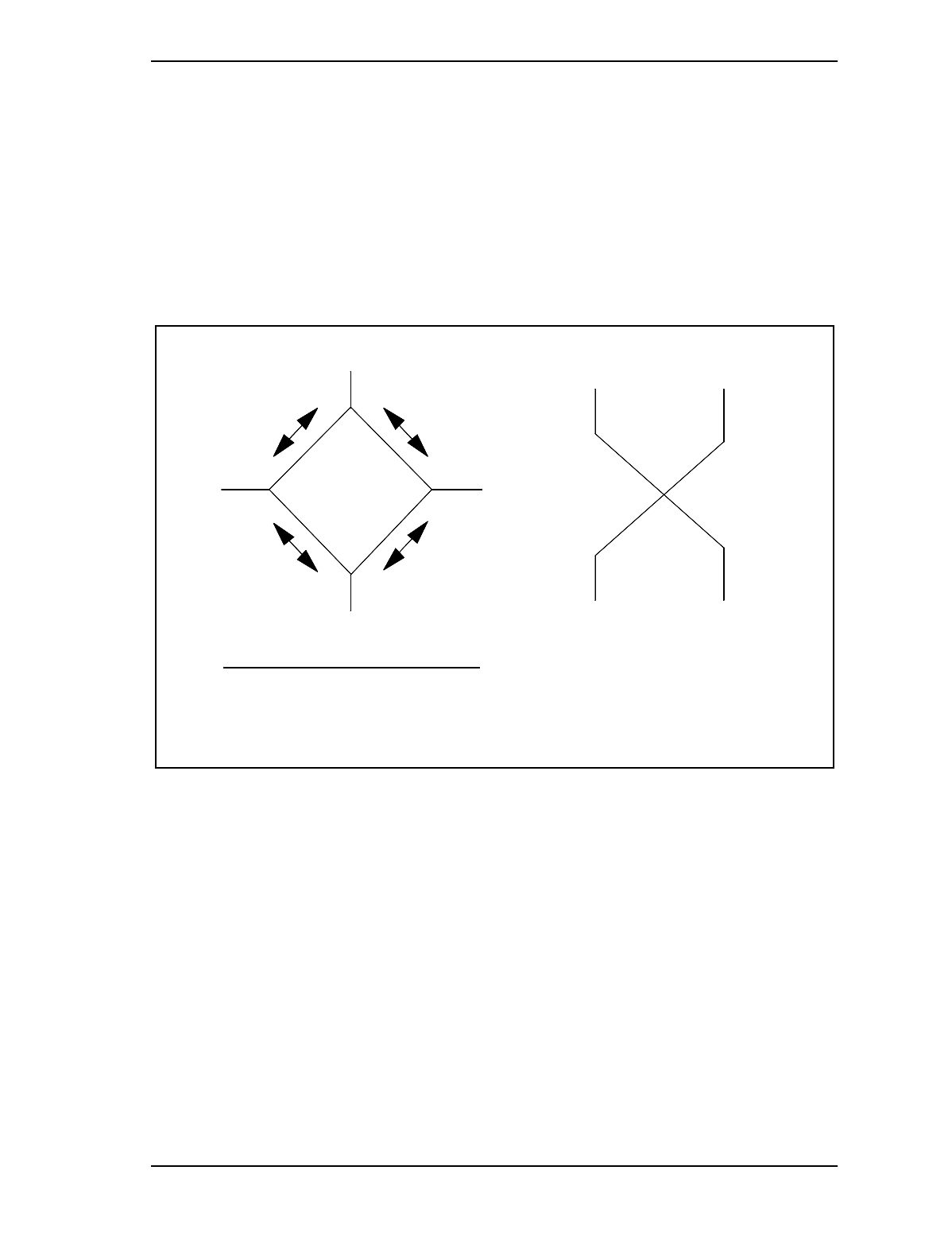
Appendix A - 4 Port Hybrid Insertion Losses
The 4 port hybrid provides isolation between opposite input ports and
between opposite output ports while providing a nominal 3.5 dB
splitting loss between adjacent inputs and outputs. Continuity is
bidirectional between adjacent Input and output ports as shown below.
Unused ports must be terminated in 50 Ohms to maintain hybrid balance
and optimum port return loss.
Last Page
IN 1
IN 2
OUT 2
4 Port Hybrid Insertion losses
Opposite ports 25 dB (typical)
Adjacent ports 3.5 dB (typical)
OUT 1
IN 1 IN 2
OUT 2
OUT 1
Equivalent schematic
used in this document.