Avaya Canada NTMQ75AA User Manual Picocell planning
Avaya Canada Corporation Picocell planning
Contents
Picocell planning

Pkgid: 0000003
PROPRIETARY INFORMATION: The information contained in this document
is the property of Nortel (Northern Telecom). Except as specifically authorized
in writing, the holder of this document shall keep all information contained
herein confidential and shall protect same in whole or in part from disclosure
and dissemination to third parties.
Nortel 1998
All Rights Reserved
Draft
Picocell 1900 General Information and
Planning
Installation Method –04-0242
September 3, 1998
Issue Number: 01.02
Information subject to change without notice. This is a DRAFT copy
for review and to provide advance information. Document release
subject to IM verification. Errors, omissions and corrections should be
sent to: lthomp@nortel.com


Picocell 1900 General Information and Planning / 3
September 3, 1998 Method 04-0242
Draft
Table of Contents
1.0 General Information . . . . . . . . . . . . . . . . . . . . . . . . . . . . . . . . . . . . . . . . . . . . . . . . . . . . . . . . 5
1.1 Description . . . . . . . . . . . . . . . . . . . . . . . . . . . . . . . . . . . . . . . . . . . . . . . . . . . . . . . . . . . . 5
1.2 Sequence . . . . . . . . . . . . . . . . . . . . . . . . . . . . . . . . . . . . . . . . . . . . . . . . . . . . . . . . . . . . . 5
1.3 Reason for Reissue. . . . . . . . . . . . . . . . . . . . . . . . . . . . . . . . . . . . . . . . . . . . . . . . . . . . . . 5
2.0 Material Requirements . . . . . . . . . . . . . . . . . . . . . . . . . . . . . . . . . . . . . . . . . . . . . . . . . . . . . . 7
2.1 Required Documents . . . . . . . . . . . . . . . . . . . . . . . . . . . . . . . . . . . . . . . . . . . . . . . . . . . . 7
System and RF Design Specification . . . . . . . . . . . . . . . . . . . . . . . . . . . . . . . . . . . . . . . . 7
3.0 Precautions and Preparations. . . . . . . . . . . . . . . . . . . . . . . . . . . . . . . . . . . . . . . . . . . . . . . . 8
3.1 Precautions . . . . . . . . . . . . . . . . . . . . . . . . . . . . . . . . . . . . . . . . . . . . . . . . . . . . . . . . . . . . 8
Indoor Installations only. . . . . . . . . . . . . . . . . . . . . . . . . . . . . . . . . . . . . . . . . . . . . . . . . . . 8
3.2 Preparations . . . . . . . . . . . . . . . . . . . . . . . . . . . . . . . . . . . . . . . . . . . . . . . . . . . . . . . . . . . 8
4.0 Installation Requirements . . . . . . . . . . . . . . . . . . . . . . . . . . . . . . . . . . . . . . . . . . . . . . . . . . . 9
4.1 Picocell Configurations. . . . . . . . . . . . . . . . . . . . . . . . . . . . . . . . . . . . . . . . . . . . . . . . . . . 9
Distributed Transceivers . . . . . . . . . . . . . . . . . . . . . . . . . . . . . . . . . . . . . . . . . . . . . . . . . 10
Distributed Antenna . . . . . . . . . . . . . . . . . . . . . . . . . . . . . . . . . . . . . . . . . . . . . . . . . . . . 11
Combined Transceivers and distributed Antenna. . . . . . . . . . . . . . . . . . . . . . . . . . . . . . 12
Combined Transceivers RF Layout . . . . . . . . . . . . . . . . . . . . . . . . . . . . . . . . . . . . . . . . 13
4.2 Picocell Physical Site Requirements. . . . . . . . . . . . . . . . . . . . . . . . . . . . . . . . . . . . . . . . 15
4.3 Picocell Remote DC Power. . . . . . . . . . . . . . . . . . . . . . . . . . . . . . . . . . . . . . . . . . . . . . . 16
4.4 Specifications . . . . . . . . . . . . . . . . . . . . . . . . . . . . . . . . . . . . . . . . . . . . . . . . . . . . . . . . . 18
Picocell Transceiver Specifications . . . . . . . . . . . . . . . . . . . . . . . . . . . . . . . . . . . . . . . . 18
Picocell Power Supply Specifications . . . . . . . . . . . . . . . . . . . . . . . . . . . . . . . . . . . . . . . 18
4.5 Environmental . . . . . . . . . . . . . . . . . . . . . . . . . . . . . . . . . . . . . . . . . . . . . . . . . . . . . . . . . 19
Picocell Base Station Environmental . . . . . . . . . . . . . . . . . . . . . . . . . . . . . . . . . . . . . . . 19
CSI Environmental . . . . . . . . . . . . . . . . . . . . . . . . . . . . . . . . . . . . . . . . . . . . . . . . . . . . . 20
4.6 Earthquake bracing requirements. . . . . . . . . . . . . . . . . . . . . . . . . . . . . . . . . . . . . . . . . . 20
Picocell Transceivers . . . . . . . . . . . . . . . . . . . . . . . . . . . . . . . . . . . . . . . . . . . . . . . . . . . 20
4.7 Commercial Power requirements . . . . . . . . . . . . . . . . . . . . . . . . . . . . . . . . . . . . . . . . . . 21
Picocell Base Station Power . . . . . . . . . . . . . . . . . . . . . . . . . . . . . . . . . . . . . . . . . . . . . . 21
CSI Power . . . . . . . . . . . . . . . . . . . . . . . . . . . . . . . . . . . . . . . . . . . . . . . . . . . . . . . . . . . 21
4.8 Picocell System interconnect. . . . . . . . . . . . . . . . . . . . . . . . . . . . . . . . . . . . . . . . . . . . . . 23
5.0 Reference Documents . . . . . . . . . . . . . . . . . . . . . . . . . . . . . . . . . . . . . . . . . . . . . . . . . . . . . 24
Appendix A - Glossary . . . . . . . . . . . . . . . . . . . . . . . . . . . . . . . . . . . . . . . . . . . . . . . . . . 25
Last Page . . . . . . . . . . . . . . . . . . . . . . . . . . . . . . . . . . . . . . . . . . . . . . . . . . . . . . . . . . . . 27

4 / Picocell 1900 General Information and Planning
Method 04-0242 September 3, 1998
Draft
Illustrations
Figure 1 – You Are Here Diagram . . . . . . . . . . . . . . . . . . . . . . . . . . . . . . . . . . . . . . . . . . . . 6
Figure 2 – Distributed Transceivers . . . . . . . . . . . . . . . . . . . . . . . . . . . . . . . . . . . . . . . . . . . .10
Figure 3 – . Distributed Antenna . . . . . . . . . . . . . . . . . . . . . . . . . . . . . . . . . . . . . . . . . . . . . . 11
Figure 4 – Combined Transceivers and Distributed Antennas . . . . . . . . . . . . . . . . . . . . . . . 12
Figure 5 – Picocell Dual 4 port Hybrid Configuration . . . . . . . . . . . . . . . . . . . . . . . . . . . . . . 13
Figure 6 – Picocell dual 8 port Hybrid Configuration . . . . . . . . . . . . . . . . . . . . . . . . . . . . . . .14
Figure 7 – Picocell MDF Block Terminations . . . . . . . . . . . . . . . . . . . . . . . . . . . . . . . . . . . . .17
Figure 8 – MTX Picocell Interconnect . . . . . . . . . . . . . . . . . . . . . . . . . . . . . . . . . . . . . . . . . .23

Picocell 1900 General Information and Planning / 5
September 3, 1998 Method 04-0242
Draft
1.0 General Information
1.1 Description
Purpose: This method covers installation information necessary to
install the Picocell cell site.
Equipment: No equipment is necessary for this section
Application: This method should be read before the installation of any
Picocell equipment.
Service Impact: None
1.2 Sequence
The sequencing for these methods is by module number reference
below:
1.3 Reason for Reissue
This is the initial release of this method.
6 / Picocell 1900 General Information and Planning
Method 04-0242 September 3, 1998
Draft
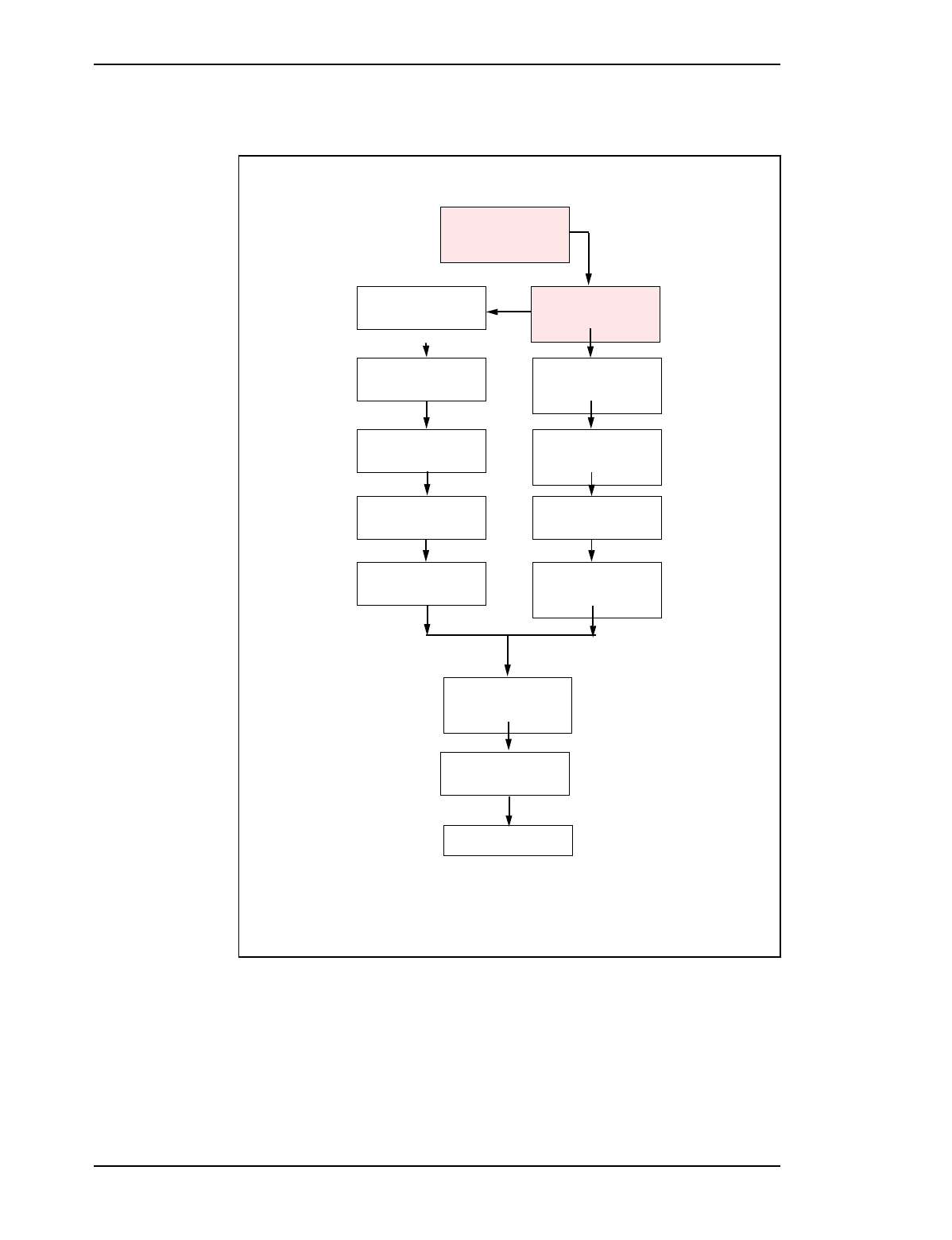
Figure 1 – You Are Here Diagram
IM 04-0242
Picocell General
Information and
Plannng
Educate Yourself
IM 04-0241
CSI Installation and
Planning
Mount the back board
and plan lay out s Check the site and
plan the Job
IM02-0242
Picocell General
Information and
Plannng
IM 04-0243
CSI Handling and
securing
Install the CSI bracket
and mount the CSI and
picocell power supplies Install Picocell mounting
bracket(s)
IM02-0245
Picocell Unit
Installattransceiverio
ntransceiver
IM 04-0243
CSI Handling and
securing
Mount the CSI cross-
connect blocks Make Picocell
Connections and lock
into bracket
IM02-0245
Picocell Unit
Installattranstranscei
verceiverion
IM 04-0244
Picocell Cabling and
Cross Connect
Cable the CSI to the
cross-connect blocks Jumper Picocell to CSI
and power supply on
cross-connect blocks
IM 04-0244
Picocell Cabling and
Cross Connect
IM 04-0246
Picocell transceiver
and CSI Power up
Power up CSI Power up Picocell
transceivers and
perform commissioning
test
IM 04-0246
Picocell transceiver
and CSI Power up
Commission Picocell
transceivers
IM28-0248
transceiver
Commisioning with the
IFR
Load CSI and
transceiver software
and run diagnostics
IM28-0247
CSI Equipment Loading
and Diagnostics
Test Integrated System IM02-0249
Picocell System Test

Picocell 1900 General Information and Planning / 7
September 3, 1998 Method 04-0242
Draft
2.0 Material Requirements
2.1 Required Documents
Installation Safety Manual (ISM/IM0) can be requested from the
Regional Tool Facility.
System and RF Design Specification
The Picocell installation should first be specified by a qualified RF
engineer for optimum placement of transceivers and performance. The
system specification details traffic and coverage requirements. If this
is not possible the Field Service personnel will have to conduct
extensive coverage testing after turn up to ensure critical areas receive
RF coverage and to identify areas where coverage may be limited. See
NTP XXX XXX for deployment guide lines and RF planning.
8 / Picocell 1900 General Information and Planning
Method 04-0242 September 3, 1998
Draft
3.0 Precautions and Preparations
3.1 Precautions
Observe the general safety precautions against personal injury and
equipment damage outlined in the ISM/IM0 at all times.
Indoor Installations only.
This method is for indoor installations only.
Picocell 1900 transceivers and antennae are for indoor installations only
and mounting of some or all; transceivers, antennae, hybrids and cabling
in an outside environment may create a potential fire hazard from
lightning. Custom design is required to address outdoor requirements
Avoid thermal trapped air cavities. In particular, the Picocell cannot be
mounted above the ceiling as this is deemed a plenum installation, and
different, tighter safety specifications are enforced.
3.2 Preparations
Prior to starting the operations presented in this method, arrange all
materials, tools, and test equipment at the work location so as to
minimize fatigue and inconvenience.
CAUTION
Maintain minimum or greater distances from interference
sources and from equipment and apparatus which may be
affected by RF energy.

Picocell 1900 General Information and Planning / 9
September 3, 1998 Method 04-0242
Draft
4.0 Installation Requirements
4.1 Picocell Configurations
PICOCELL 1900 employs dual transceivers, which are distributed in a
typical commercial building environment. Standard building telephone
wiring connects the TCM digital link between the transceivers and the
CSI. The CSI in the building location connects to the MTX over
standard Telco digital T1or E1 facilities. Transceivers are equipped with
internal Omni antennae and provide RF coverage from a wall or ceiling
location. External antennae options are also supported and described
here.
To provide flexibility in providing RF coverage in building
environments and to provide flexibility in meeting traffic requirements
the PICOCELL 1900 transceivers may be connected to external
antennae either directly or combined through RF hybrids. Flexibility in
RF coverage may also be enhanced with external antennae connected
directly to the transceiver and the antenna placed for optimum RF
coverage around barriers and obstacles and in select areas.
The RF channels in the individual PICOCELL 1900 transceivers are
equipped with duplexed transmitters and dual receivers to provide path
diversity in the mobile to base station path. The transmitters are hybrid
combined internally to both antenna ports which are also duplexed to
each receiver. Therefore RF signals from each antenna port connecting
to the dual receivers provide diversity over two RF paths.
Traffic capacity and RF coverage may also be optimized by combining
several transceivers on several antennae through multi port RF hybrids,
each antenna providing coverage for multiple RF channels. Refer to
NTP-XXX-YYY for deployment rules governing RF coverage and
traffic requirements.
Three configurations are supported:
• 1. DISTRIBUTED TRANSCEIVERS
• 2. DISTRIBUTED ANTENNAE
• 3. COMBINED TRANSCEIVERS AND DISTRIBUTED
ANTENNAE.
10 / Picocell 1900 General Information and Planning
Method 04-0242 September 3, 1998
Draft
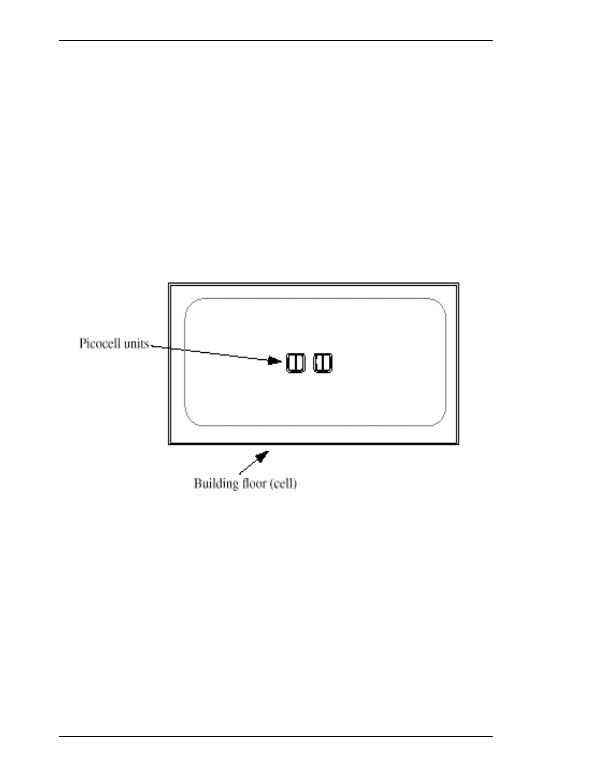
Distributed Transceivers
One or more transceivers equipped with internal antennae are
distributed through an indoor building environment as shown in Figure
2. RF coverage and traffic engineering rely on the coverage area and
traffic capacity provided by the physical placement of each transceiver.
Using this arrangement, filling in high traffic areas and spot coverage
requires the placement of individual transceivers at central points in the
desired coverage area. Traffic capacity is determined by the number of
Picocell transceivers in the coverage area. The TDMA 1900 mobile
units are served with Digital traffic channels and Digital Control
channels as determined by rules outlined in the Picocell Deployment
Guide.
Figure 2 – Distributed Transceivers
Picocell 1900 General Information and Planning / 11
September 3, 1998 Method 04-0242
Draft
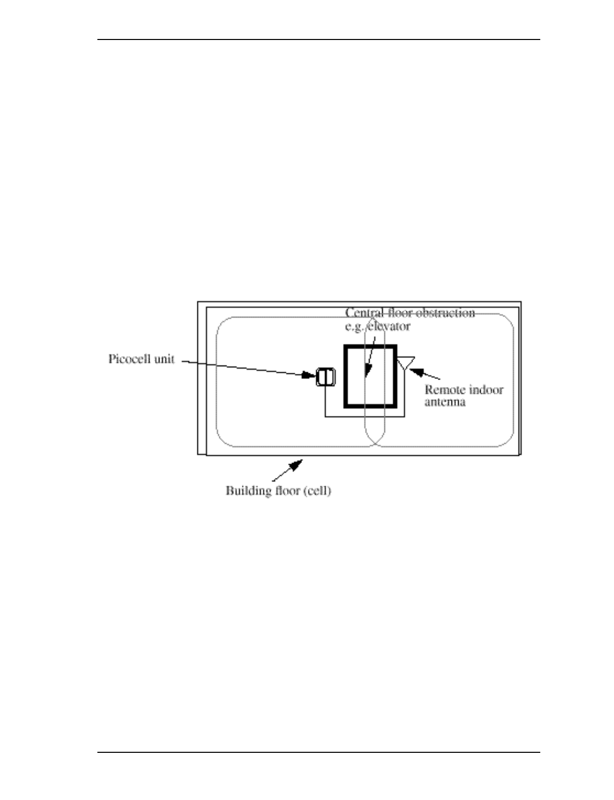
Distributed Antenna
External antennas may be connected to the Picocell transceivers and
located remotely from the transceiver location. This provides flexibility
for optimizing RF coverage and working around restrictions for
mounting the transceivers. The internal antennae equipped in each
Picocell transceiver is disabled when remote antennae are connected and
permits the RF coverage area to be determined by placement of the
antennae and not the transceiver. The remote antenna option can be
used to provide coverage over shadowed areas where physical
deployment of the transceiver has an obstruction which blocks RF
coverage and where it is impractical to locate the Picocell transceiver
Figure 3 – . Distributed Antenna
12 / Picocell 1900 General Information and Planning
Method 04-0242 September 3, 1998
Draft
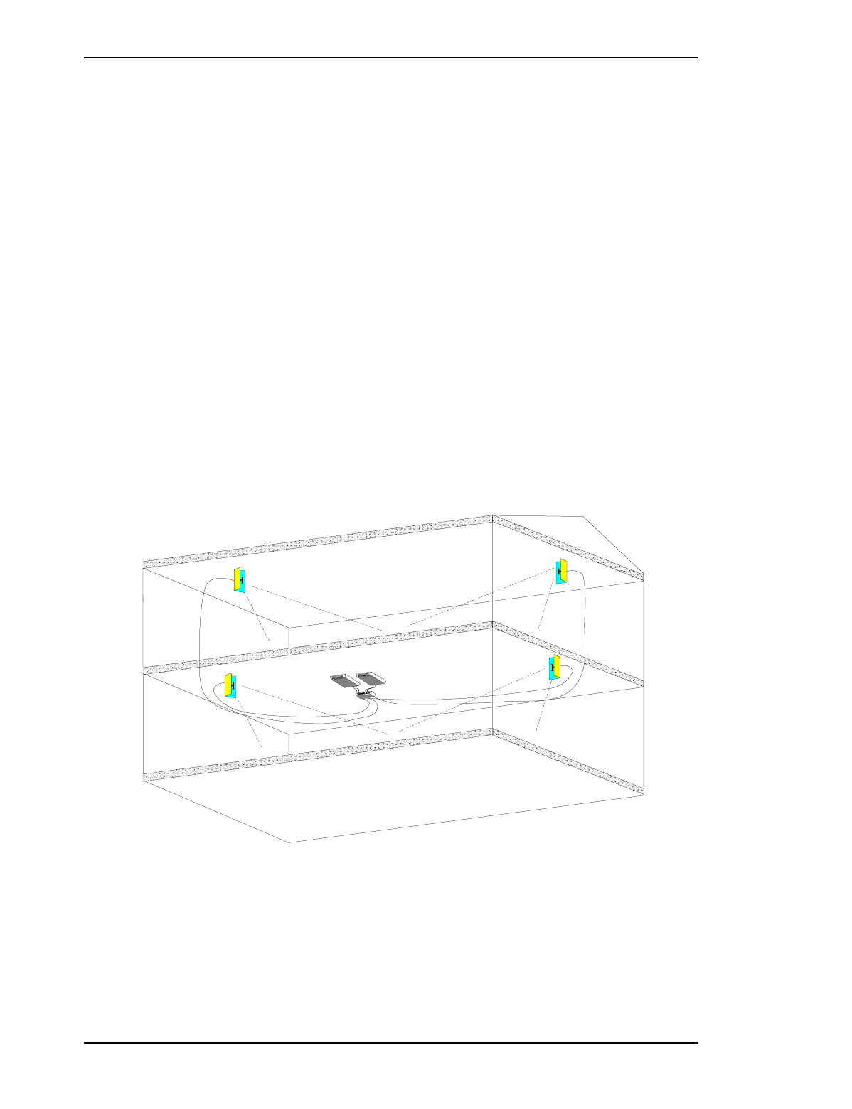
Combined Transceivers and distributed Antenna.
Transceivers may be combined with multiple antennas to increase both
traffic capacity and RF coverage in a cell partition. Figure 4 shows the
distribution of external antennas with two transceivers combined
together. Hybrids are used to combine two to four Picocell transceivers
with an external antenna network up to 8 antennas. Combining uses
either a dual 4 port or dual 8 port combining hybrid. The dual 4 port
hybrid has 4 inputs and 4 outputs and connects all 4 RF channels to each
of the 4 antennas. The dual 8 port hybrid has 8 inputs and 8 outputs and
connects all 8 RF channels to each of the 8 antennas. Low-loss coaxial
cables connect between the antennae, hybrids and transceivers. See IM
12-0152 for cable types.
Figure 4 illustrates a multi floor application with distributed antennas
on 2 floors and the combined transceivers mounted on the first floor.
Antenna placement and resulting coverage must be determined by the
System Engineer and should be listed in the System design and layout
document. Ensure system layout and mounting information is available
before starting the installation.
Figure 4 – Combined Transceivers and Distributed Antennas
Picocell 1900 General Information and Planning / 13
September 3, 1998 Method 04-0242
Draft
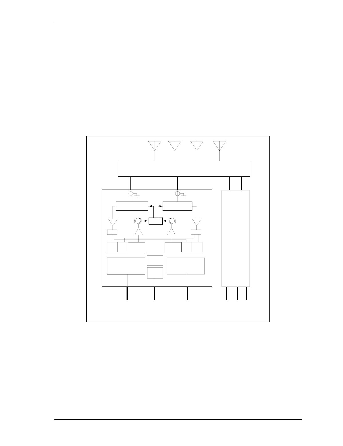
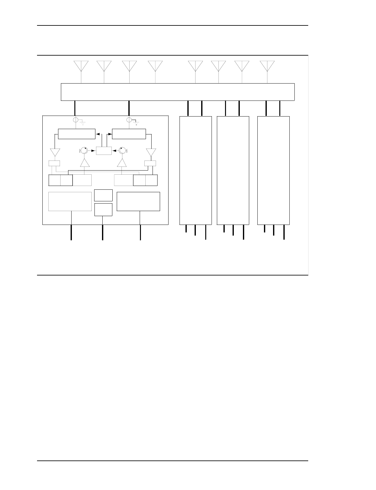
Combined Transceivers RF Layout
Multiple Picocell transceivers may be combined on antennas using
hybrids. Each picocell transceiver connects to two antennas which may
either be internal to the unit or cabled to external antennas. The
transmitters of both RF transceiver channels are combined through an
internal hybrid to broadcast on each transceiver antenna port. External
hybrids are used to connect multiple Picocell transceivers to multiple
antennae as shown in Figure 5 and Figure 6.
Figure 5 – Picocell Dual 4 port Hybrid Configuration
Rx A Rx B Tx
Tx
Rx A
Rx BTx
Rx Tx
ANT ANT Rx
IsolatorIsolator
PSMO
PUP
-48VDC T R
T R
Base Band A Base Band B
TCM
A
TCM
BVDC
-48
TCM TCM
Hybrid
-48
VDC TCM
B
TCM
A
Hybrid
PICOCELL
PICOCELL #1
#2
14 / Picocell 1900 General Information and Planning
Method 04-0242 September 3, 1998
Draft
Figure 6 – Picocell dual 8 port Hybrid Configuration
Rx A
Base Band B
TCM
T R
TCM
TCM
A B
Rx A Rx B Tx Tx
PSMO
PUP
-48VDC
T R
Base Band A
TCM
Rx B
IsolatorIsolator
Hybrid
#2 #4
ANT
Tx
Rx Tx
ANT Rx
Hybrid
PICOCELL PICOCELL
-48VDC/
GRD
PICOCELL #1
#3
PICOCELL
TCM
-48
VDC
TCM
B
ATCM
-48
VDC
TCM
B
ATCM
-48
VDC
TCM
B
A

Picocell 1900 General Information and Planning / 15
September 3, 1998 Method 04-0242
Draft
4.2 Picocell Physical Site Requirements
This section covers the physical site requirements necessary to install
the Picocell Equipment.
Installation of the Remote antenna option must consider mounting of
antennae, transceivers, the interconnecting coaxial cable and TCM
wiring. Cables must be supported in cable tray, routed in conduit or tied
in intervals and must not violate building and fire codes. The System
design Specification and layout must specify these parameters to ensure
that the cable types and routes meets building codes.
transceivers and antennae must not be mounted behind obstacles and if
it is impractical to do so then external antennae may be required.
Mounting constraints on antennae are more flexible due to the lighter
weight and smaller size. The ceiling antenna may be secured directly to
ceiling panels and the directional antenna to dry wall surfaces using
common anchor hardware. The Picocell transceiver requires support for
ceiling mounting. See IM 12-0152 and IM 02-0245 for mounting
details.
Installation of the combined Picocell applications require the
transceivers to be cabled to an external hybrid combiner. This will
operate multiple transceivers to serve a large area on antennas
distributed throughout the building. The antennae are connected to the
hybrid combiner by low-loss coaxial cables. Mounting of the Hybrids,
transceivers and cabling must consider the cable routing options, power
options and location. It may be required to provide a plywood back
board to support the combined Picocell transceivers and hybrids.
Transceivers co-located with power supplies will require individual AC
outlets at the transceiver locations. IF transceiver power is remoted from
the CSI location then outlets must be provided to accommodate all
power convertors, see next section: "Picocell Power"
16 / Picocell 1900 General Information and Planning
Method 04-0242 September 3, 1998
Draft
4.3 Picocell Remote DC Power
Picocell power may be remoted through station wiring or co-located
with the Picocell transceiver. Co-located power requires an AC outlet
close to the Picocell transceiver. Refer to the System Design
Specification to confirm AC outlet requirements.
Remote power requires that the cable resistance be accounted for in
order to ensure that the voltage drop over the pair does not reduce the
voltage below minimum requirements at the Picocell transceiver. More
conductors may be employed to reduce voltage drop and pairs may be
doubled up to meet the resistance requirements. Table 1 on page 16
outlines the maximum length of 24 AWG cable allowable between the
Picocell transceiver and the remote AC/DC power convertor. The
following assumptions have been made:
24 AWG twisted pair
-48 volts minimum from the AC/DC convertor
-30 volts minimum into the Picocell transceiver
Worst Case Picocell transceiver Power
Heat Dissipation and Number of 24 AWG Twisted Pairs used for
powering
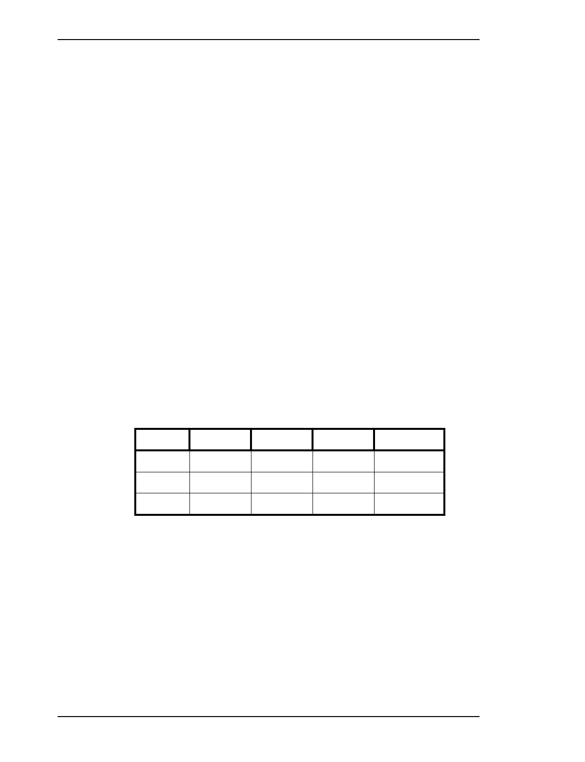
Table 1 – Max Power Cable Length (24 ga) for Picocell
Note: To calculate the distance with 26 AWG wire, scale distances by 0.629 To
calculate the distance with 22 AWG wire, scale distances by 1.599
Note: The Picocell nominal maximum DC power drain design is 32W. The DC
distribution range is limited since the PUPS will shut down if the voltage drops
below -30V. The 36W range numbers should be used for the worst case for
maximum load, all transmitters on.
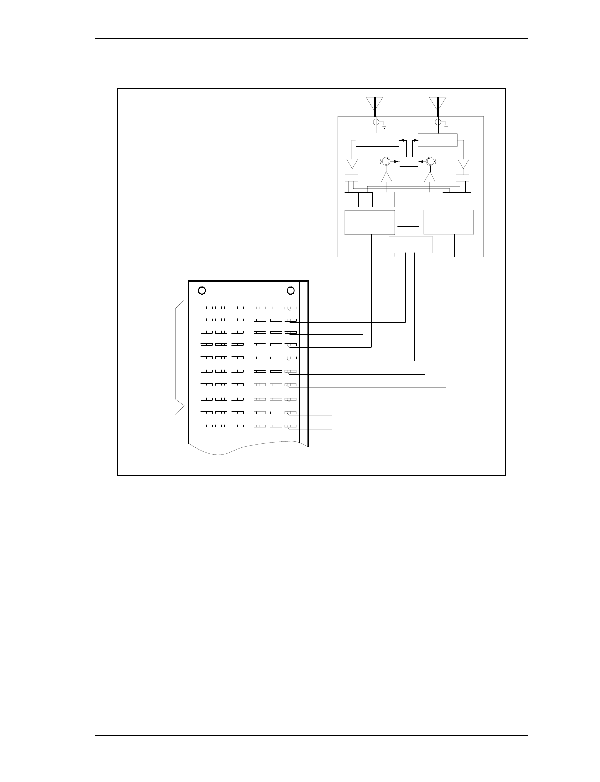
It is expected that a typical, in-building connection from the Picocell
will be via 4-pair station wiring, with 2-pair for DC powering, and 2-pair
for the TCM feeds. Figure 7 illustrates the picocell transceiver
terminations on the MDF terminal block. This arrangement is intended
to isolate ground and battery on the block to minimize accidental
shorting.
Heat 4 pair 3 pair 2 pair 1 pair
40 Watts 1042 feet 782 feet 521 feet 261 feet
36 Watts 1158 feet 868 feet 579 feet 289 feet
32 Watts 1303 feet 977 feet 651 feet 326 feet
Picocell 1900 General Information and Planning / 17
September 3, 1998 Method 04-0242
Draft
Figure 7 – Picocell MDF Block Terminations
Isolator
ANT
Base Band B
A
-48VDC
Grd
T
R
Grd
Grd
R
-48VDC
T
Grd
Radio
Unit 1
Radio
Unit 2
TCM
TCM
TCM
TCM
Hybrid
-48VDC
TCM
Rx A Rx B Tx
PSMO
Rx Tx
ANT
Isolator
GRD
PUP
T R
Tx
Tx
PICOCELL
1900
Base Band A
Transceiver
B
Rx B
TCM
Rx A
Rx
T R

18 / Picocell 1900 General Information and Planning
Method 04-0242 September 3, 1998
Draft
4.4 Specifications
Picocell Transceiver Specifications
• Maximum length twisted pair distribution, 3000’ (TCM)
• Maximum length remote Power (see section 4.2)
• 1900MHz Version IS 136 TDMA operation
• 100mW (+20dBm) ERP
• 2 RF channels per picocell transceiver (Internal duplexer)
• Internal Omni Antenna or External Omni and Directional Antennae
• Receiver Diversity
• Distributed Antenna Support
• Two twisted pair per transceiver for signaling (TCM)
• 48 Volt DC power 32W nominal
• No external grounding is required on the Picocell 1900 transceiver.
• Visually pleasing, non-obtrusive design
• 15 Picocells per CSI (30 RF channels)
• Standard Nortel TRU maintenance interface.
• 12.8" W x 13.6" L x 3.25" D
• 14 lb transceiver weight
Picocell Power Supply Specifications
Input • Voltage: 120/240 VAC
• Line Frequency 50/60 Hz
• Power rating 90W
• Protection Internal primary current fuse, Inrush limiting
• Configuration In Case IEC320 with Ground
• 6 ft., 5 Conductor, 18 AWG,
Output •Voltage -48VDC +/- .5V
•Nominal current 2.0 A Max.
•Combined Line and Load Voltage Regulation
• output current limiting
• Short circuit protection
•Barrier strip, screw terminal
Mechanical •6.58 L x 4.0 W x 1.25 H(in)
• Case Material: Black 94V0 Polycarbonate
• Weight: 22 ounces, 625 grams (excluding cords)

Picocell 1900 General Information and Planning / 19
September 3, 1998 Method 04-0242
Draft
4.5 Environmental
Picocell Base Station Environmental
• The room must be clean and well ventilated. Each Picocell
transceiver can dissipate up to 40 Watts maximum of power in the
form of heat( 134 BTU per hour.) Equipment ventilation must be
sufficient to maintain the temperature at an acceptable level.
• Indoor use only, cabling, antennae, hybrids and Picocell
transceivers.
• Avoid thermal trapped air cavities. In particular, the Picocell cannot
be mounted above the ceiling as this is deemed a plenum
installation, and different, tighter safety specifications apply.
• The acceptable temperature levels are listed below:
•5
o and 40o C (41o and 105o F) Continuous Operation
• The humidity is maintained between 5% and 90% RH (non-
condensing) at 40o C worst case temperature and not to exceed 0.024
lbs of water per pound of dry air for continuous operation.
• The Picocell will function from the altitude of 60m (197ft) below sea
level to 4000m (13,000ft) above sea level. The maximum
operational temperature requirement will be de-rated by 2oC (3.6oF)
per 304m (1000ft) for altitudes above 2134 m (7000 ft).
• The location selected to mount the Picocell is not subject to constant
vibration.
• The Picocell is located at least 12ft (3660 mm) away from any
source of electrostatic and electromagnetic energy. These sources
may include:
•Power Tools
•Appliances (such as vacuum cleaners)
•Office Business Machines (such as copying machines)
•All Electric Motors
•Electrical Transformer

20 / Picocell 1900 General Information and Planning
Method 04-0242 September 3, 1998
Draft
CSI Environmental
• The CSI is designed to operate in a Customer Premises Equipment
(CPE) environment.
The Acceptable temperature levels are listed below:
•5
o and 40o C (41o and 105o F) Continuous Operation
• The humidity is maintained between 20% and 80% RH (non-
condensing) at 40o C worst case temperature and not to exceed 0.024
lbs of water per pound of dry air for continuous operation.
• The CSI will function at an altitude of up to 5000 m (16,000 ft). The
maximum operational temperature requirement will be de-rated by
2oC (3.6oF) per 304m (1000ft) for altitudes above 2134m (7000 ft).
• The CSI weighs approximately 40 pounds fully configured and has
dimensions of: height 25 5/8 in, width 13 in and depth 13 3/4 in.
4.6 Earthquake bracing requirements
Picocell Transceivers
False ceiling mounting requires ceiling track mounting hanger clips
equipped with drop support wires. Wall mounting requires mounting
on wall studs or 3/4 inch plywood back board.

Picocell 1900 General Information and Planning / 21
September 3, 1998 Method 04-0242
Draft
4.7 Commercial Power requirements
Picocell Base Station Power
• The Picocell Base Station is available for Remote DC and co-located
DC from a local AC power outlet.
• Picocell 1900 requires a non-switched dedicated power convertor
for each Picocell transceiver. The power cord is 6.5 ft (2 meters)
in length.
• Power convertor dimensions: 6.5"L x 4" W x 1.25" D (allow space
for power cords)
Each non-switched dedicated outlet must have the following:
• Voltage110 - 120 VAC
• Frequency47Hz to 53Hz or 57 Hz to 63 Hz
• Power (I/P max)100 VA
• Receptacles-120V 15A service NEMA IG 5-15R
• -208/240V 15A service IG 6 15R
CSI Power
The CSI is available for AC power only and requires a non-switched
dedicated power outlet per cabinet, convenient to the bottom of the CSI.
An equipment grounding conductor that is not smaller in size than the
ungrounded branch-circuit supply conductors is to be installed as part of
the circuit that supplies the product. Bare, covered, or insulated
grounding conductors are acceptable. Individually covered or insulated
equipment grounding conductors shall have a continuous outer finish
that is either green, or green with one or more yellow stripes. The
equipment grounding conductor is to be connected to ground at the
service equipment.
The attachment-plug receptacles in the vicinity of the product are all to
be of a grounding type, and the equipment grounding conductors serving
there receptacles are to be connected to earth ground at the service
equipment.
Each non-switched dedicated outlet must have the following:
• Voltage115 VAC
• Frequency47Hz to 53Hz or 57 Hz to 63 Hz
• Power (I/P max)300 VA
22 / Picocell 1900 General Information and Planning
Method 04-0242 September 3, 1998
Draft
• Receptacles-120VAC, 15A service NEMA IG 5-15R
• -208/240V 15A service IG 6 15R
• Distance between the AC outlet and CSI must accommodate the 6ft
CSI power cord. Warnings for AC power cord:
WARNING
The socket-outlet shall be installed near the equipment and shall be
easily accessible.
CAUTION
Maintain minimum or greater distances from interference
sources and from equipment and apparatus which may be
affected by RF energy.
Picocell 1900 General Information and Planning / 23
September 3, 1998 Method 04-0242
Draft
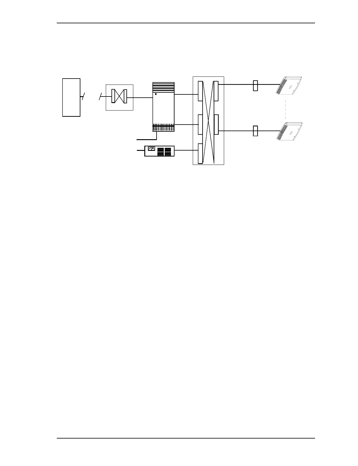
4.8 Picocell System interconnect.
Figure 8 – MTX Picocell Interconnect
CSI
110/120
VAC
MTX Telco
Facility DS1
DSX Cross connect
-48VDC
TCM
1-15
TCM
16-30
Cross Connect
TCM
Building House cables
to Picocell radios 1-15
1
15
Picocell Radio un
Picocell Radio un
Ceiling or
Wall Box
Ceiling or
Wall Box

24 / Picocell 1900 General Information and Planning
Method 04-0242 September 3, 1998
Draft
5.0 Reference Documents
Document Number Title
IM 04-0241 Picocell1900 CSI Installation and Planning
IM 04-0242 Picocell1900 General Information and Planning
IM 08-0243 Picocell1900 CSI Equipment Handling and Secur-
ing
IM 04-0244 Picocell1900 System Cabling and Cross Connect
IM 12-0152 Picocell1900 Antenna System Installation
IM 02-0245 Picocell1900 transceiver Installation
IM 22-0246 Picocell1900 transceiver and CSI Power up
IM 24-0247 Picocell1900 Equipment Loading and Diagnostics
IM 28-0248 Picocell1900 transceiver Commissioning with the
IFR 1900
IM 28-0249 Picocell1900 System Test

Picocell 1900 General Information and Planning / 25
September 3, 1998 Method 04-0242
Draft
Appendix A – Glossary
AC Alternating Current
AMO Antenna Matrix/Oscillator
APS Alarm and Power Supply
AWG American Wiring Gauge
CSI Compact Simplex ICRM
DDU Disk Drive Unit
DF Distributiottransceiverransceivern Frame
DS1 Digital Signaling 1
ICRM Integrated Cellular Remote Module
MAP Maintenance Administration Position
Picocell Picocell Base Station transceiver
MTX Mobile Telephone eXchange
PEC Product Engineering Code
PM Peripheral Module
SLM System Loading Module
T1 First level digital signal (DS1), 1.544Mb/sec
TCM Time Compression Multiplex
TRU Transmit Receive Unit
transceiver

26 / Picocell 1900 General Information and Planning
Method 04-0242 September 3, 1998
Draft
Picocell Installation Planning Checklist
Location: __________________ Office: ______________ Date: ___/___/___
COEO # _______ Customer:
Number of CSI's to be installed
Number of Picocell 's to be installed
Start Date __/__/__ Completion Date __/__/__
General Description of Work:
Responsible person/s for this project are:
Installation Personnel Customer Representative
Name: _________________________ ________________________
Title: __________________________ ________________________
Tel# __________________________ ________________________
Size of the room: ft _____________in
What type of building construction? concrete, wood etc.
Will the Base Stations be mounted on the wall or Ceiling?
Is the desired Picocell (s) location within 4.5 ft of the desired Hybrid location?
If not, what is the distance between the two?
Is the desired Picocell equipment location within the preset cable and power cord
lengths? . (Yes or No)
If not, what are the distances between the equipment?
Will there be room for additional equipment if needed? (Yes Or No)
Is the room size adequate for installation? (Yes Or No)
Is the cooling adequate for the room with equipment? (Yes Or No)
Is there a backboard installed? (Yes Or No)
Is there room for a backboard?(Yes Or No)
What type of wall construction was used? Circle stud spacing and stud type.

Picocell 1900 General Information and Planning / 27
September 3, 1998 Method 04-0242
Draft
16in 20in 24in stud spacing Wood Steel Concrete stud type
Are there sufficient AC outlets in the room?(Yes Or No)
If "NO", specify quantity. AC outlets should be dedicated and be within 6ft of the equip-
ment being mounted.
Does the Room have cable MDF?(Yes Or No)
What other type of equipment is in the room?
Does a ground cable have to be run?
Is a ladder needed to install the equipment? How Big
How many?_______________Where?
How will antenna cabling be run?
Will more cable than specified be required to install the antennae?
If more cable is necessary does it meet with the engineering specifications?
Can the antennae be mounted where specified?
Last Page

28 / Picocell 1900 General Information and Planning
Method 04-0242 September 3, 1998
Draft