Avaya Canada NTMQ75AA User Manual 05 08 0245 radio Installation1 02
Avaya Canada Corporation 05 08 0245 radio Installation1 02
Contents
Installation

Pkgid: 0000003
PROPRIETARY INFORMATION: The information contained in this document
is the property of Nortel (Northern Telecom). Except as specifically authorized
in writing, the holder of this document shall keep all information contained
herein confidential and shall protect same in whole or in part from disclosure
and dissemination to third parties.
Nortel 1998
All Rights Reserved
Draft
Picocell 1900 Radio Unit Installation
Installation Method – 02-0245
September 3, 1998
Issue Number: 01.02
Information subject to change without notice. This is a DRAFT copy
for review and to provide advance information. Document release
subject to IM verification. Errors, omissions and corrections should be
sent to: lthomp@nortel.com


Picocell 1900 Radio Unit Installation / 3
September 3, 1998 Method 02-0245
Draft
Table of Contents
1.0 General Information . . . . . . . . . . . . . . . . . . . . . . . . . . . . . . . . . . . . . . . . . . . . . . . . . . . . . . . 7
1.1 Description . . . . . . . . . . . . . . . . . . . . . . . . . . . . . . . . . . . . . . . . . . . . . . . . . . . . . . . . . . . . 7
1.2 Sequence . . . . . . . . . . . . . . . . . . . . . . . . . . . . . . . . . . . . . . . . . . . . . . . . . . . . . . . . . . . . . 7
1.3 Reason for Reissue . . . . . . . . . . . . . . . . . . . . . . . . . . . . . . . . . . . . . . . . . . . . . . . . . . . . . . 7
2.0 Material Requirements . . . . . . . . . . . . . . . . . . . . . . . . . . . . . . . . . . . . . . . . . . . . . . . . . . . . . 9
2.1 Required Documents . . . . . . . . . . . . . . . . . . . . . . . . . . . . . . . . . . . . . . . . . . . . . . . . . . . . 9
2.2 Tools . . . . . . . . . . . . . . . . . . . . . . . . . . . . . . . . . . . . . . . . . . . . . . . . . . . . . . . . . . . . . . . . . 9
2.3 Stock List and Mounting Kits . . . . . . . . . . . . . . . . . . . . . . . . . . . . . . . . . . . . . . . . . . . . . . 9
2.4 Customer Supplied Equipment . . . . . . . . . . . . . . . . . . . . . . . . . . . . . . . . . . . . . . . . . . . . 10
3.0 Precautions and Preparations . . . . . . . . . . . . . . . . . . . . . . . . . . . . . . . . . . . . . . . . . . . . . . 11
3.1 Precautions . . . . . . . . . . . . . . . . . . . . . . . . . . . . . . . . . . . . . . . . . . . . . . . . . . . . . . . . . . . 11
3.2 Preparations . . . . . . . . . . . . . . . . . . . . . . . . . . . . . . . . . . . . . . . . . . . . . . . . . . . . . . . . . . 11
4.0 Procedure . . . . . . . . . . . . . . . . . . . . . . . . . . . . . . . . . . . . . . . . . . . . . . . . . . . . . . . . . . . . . . . 13
4.1 Overview . . . . . . . . . . . . . . . . . . . . . . . . . . . . . . . . . . . . . . . . . . . . . . . . . . . . . . . . . . . . . 13
Procedure 1 – Unpacking and Inventory transciever Material . . . . . . . . . . . . . . . . 14
Procedure 2 – Wall Mounting and securing the Radio Mounting Bracket . . . . . . . 15
Procedure 3 – Ceiling Mounting and securing the Radio Mounting Bracket . . . . . 17
Procedure 4 – Installation of PICOCELL Transceiver onto Wall Mounting Bracket 19
Procedure 5 – Co-located AC power supply Installation . . . . . . . . . . . . . . . . . . . 20
Procedure 6 – Remote AC power supply Installation . . . . . . . . . . . . . . . . . . . . . . 21
4.2 Power Supply connections . . . . . . . . . . . . . . . . . . . . . . . . . . . . . . . . . . . . . . . . . . . . . . . 22
4.3 PICOCELL Transceiver Connections . . . . . . . . . . . . . . . . . . . . . . . . . . . . . . . . . . . . . . . 23
5.0 References . . . . . . . . . . . . . . . . . . . . . . . . . . . . . . . . . . . . . . . . . . . . . . . . . . . . . . . . . . . . 24
6.0 Appendices . . . . . . . . . . . . . . . . . . . . . . . . . . . . . . . . . . . . . . . . . . . . . . . . . . . . . . . . . . . . . 25
Appendix A - PICOCELL 1900 transciever Cover removed Top view . . . . . . . . . . . . . . 25
Appendix B - Mounting Orientation and Isolation . . . . . . . . . . . . . . . . . . . . . . . . . . . . . . 26
Appendix C - Picocell 1900 Technical Specifications . . . . . . . . . . . . . . . . . . . . . . . . . . . 27
AC REQUIREMENTS . . . . . . . . . . . . . . . . . . . . . . . . . . . . . . . . . . . . . . . . . . . . . . . . . . 27
Picocell 1900 Power Supply Specifications . . . . . . . . . . . . . . . . . . . . . . . . . . . . . . . . . . 28
Last Page . . . . . . . . . . . . . . . . . . . . . . . . . . . . . . . . . . . . . . . . . . . . . . . . . . . . . . . . . . . . . 28

4 / Picocell 1900 Radio Unit Installation
Method 02-0245 September 3, 1998
Draft

Picocell 1900 Radio Unit Installation / 5
September 3, 1998 Method 02-0245
Draft
Illustrations
Figure 1 – You are here diagram . . . . . . . . . . . . . . . . . . . . . . . . . . . . . . . . . . . . . . . . . . . . . . 8
Figure 2 – PICOCELL 1900 front view . . . . . . . . . . . . . . . . . . . . . . . . . . . . . . . . . . . . . . . . . 10
Figure 3 – PICOCELL 1900 transciever Assembly . . . . . . . . . . . . . . . . . . . . . . . . . . . . . . . . 12
Figure 4 – PICOCELL 1900 Bottom view . . . . . . . . . . . . . . . . . . . . . . . . . . . . . . . . . . . . . . . 16
Figure 5 – PICOCELL 1900 Wall Mount . . . . . . . . . . . . . . . . . . . . . . . . . . . . . . . . . . . . . . . 16
Figure 6 – Track Ceiling support IDSClips . . . . . . . . . . . . . . . . . . . . . . . . . . . . . . . . . . . . . . 18
Figure 7 – PICOCELL 1900 transciever Ceiling mounting . . . . . . . . . . . . . . . . . . . . . . . . . . 18
Figure 8 – Locking the transciever into the mounting Bracket . . . . . . . . . . . . . . . . . . . . . . . . 19
Figure 9 – PICOCELL 1900 Co-located power supply . . . . . . . . . . . . . . . . . . . . . . . . . . . . . 20
Figure 10 – Remote Power Supply Mounting (Typical) . . . . . . . . . . . . . . . . . . . . . . . . . . . . . 21
Figure 11 – Power supply and connections . . . . . . . . . . . . . . . . . . . . . . . . . . . . . . . . . . . . . . 22
Figure 12 – PICOCELL 1900 transciever Connections . . . . . . . . . . . . . . . . . . . . . . . . . . . . . 23
Figure 13 – PICOCELL 1900 cabling and connections . . . . . . . . . . . . . . . . . . . . . . . . . . . . 23

6 / Picocell 1900 Radio Unit Installation
Method 02-0245 September 3, 1998
Draft
Tables
Tools 13
Stock List and Mounting Kits 14
Mounting Hardware 14

Picocell 1900 Radio Unit Installation / 7
September 3, 1998 Method 02-0245
Draft
1.0 General Information
1.1 Description
Purpose: This method will describe how to unpack and install the
PICOCELL 1900 Transceiver).
Equipment: The PICOCELL 1900 Transceiver and mounting
hardware.
Application: This method will cover installation of initials, upgrades
and extensions.
Service Impact: There is no service impact at this time.
1.2 Sequence
1. This method is to be performed after the building cabling has been
installed and is ready to recieve the PICOCELL 1900 Transceivers.
2. PICOCELL 1900 Planning Method 04-0242 has been reviewed.
1.3 Reason for Reissue
Changes from Project Team Review Sept 1, 1998:
• Updated section 4.2 Power supply
• Revised figures 5, 8, 9
• Section 5 removed reference
• Global change MBS1900 to Picocell 1900
• Cleared Table 3 contents until mounting hardware is finalized
8 / Picocell 1900 Radio Unit Installation
Method 02-0245 September 3, 1998
Draft
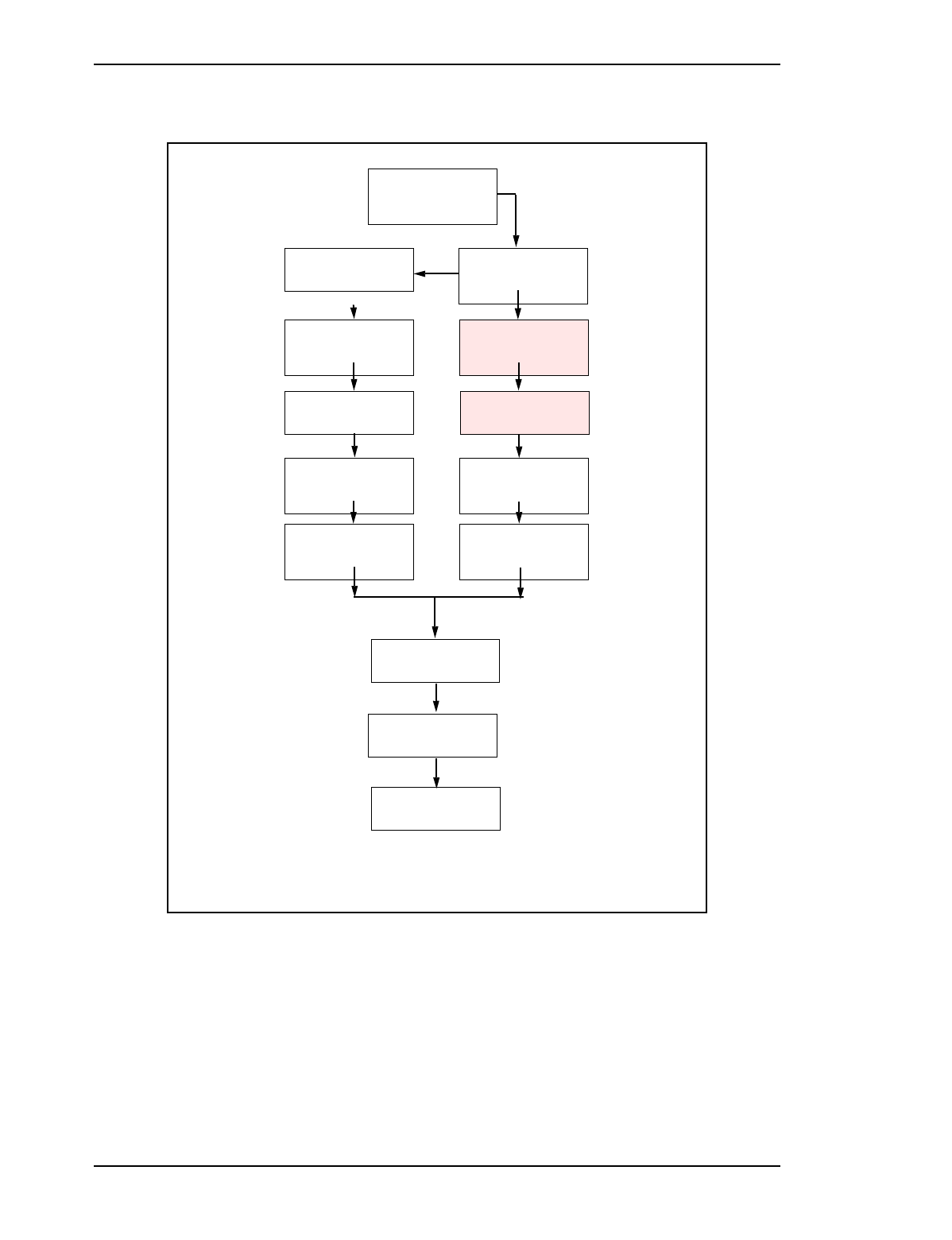
Figure 1 – You are here diagram
IM 04-0242
PICOCELL 1900
General Information
and Plannng
Educate Yourself
IM 04-0241
CSI Installation and
Planning
Mount the back board
and plan lay out s Check the site and plan
the Job
IM02-0242
PICOCELL 1900
General Information
and Plannng
IM 04-0243
CSI Handling and
securing
Install the CSI bracket
and mount the CSI and
PICOCELL 1900 power
supplies
Install PICOCELL 1900
mounting bracket(s),
Hybrids and Antennas
IM02-0245, 12-0152
PICOCELL 1900 Unit
and Antenna
Installation
IM 04-0243
CSI Handling and
securing
Mount the CSI cross-
connect blocks
Make PICOCELL 1900
Connections and lock
into bracket
IM02-0245
PICOCELL 1900 Unit
Installation
IM 04-0244
PICOCELL 1900
Cabling and Cross
Connect
Cable the CSI to the
cross-connect blocks
Jumper PICOCELL
1900 to CSI and power
supply on cross-connect
blocks
IM 04-0244
PICOCELL 1900
Cabling and Cross
Connect
IM 04-0246
PICOCELL 1900
Radio and CSI Power
up
Power up CSI Power up PICOCELL
1900 Radios and
perform commissioning
test
IM 04-0246
PICOCELL 1900
Radio and CSI Power
up
Commission PICOCELL
1900 transcievers
IM28-0248
Radio Commisioning with
the IFR
Load CSI and Radio
software and run
diagnostics
IM28-0247
CSI Equipment Loading
and Diagnostics
Test Integrated System IM02-0249
Microcell System
Test

Picocell 1900 Radio Unit Installation / 9
September 3, 1998 Method 02-0245
Draft
2.0 Material Requirements
2.1 Required Documents
Installation Safety Manual (ISM/IM0) - can be requested from the
Regional Tool Facility.
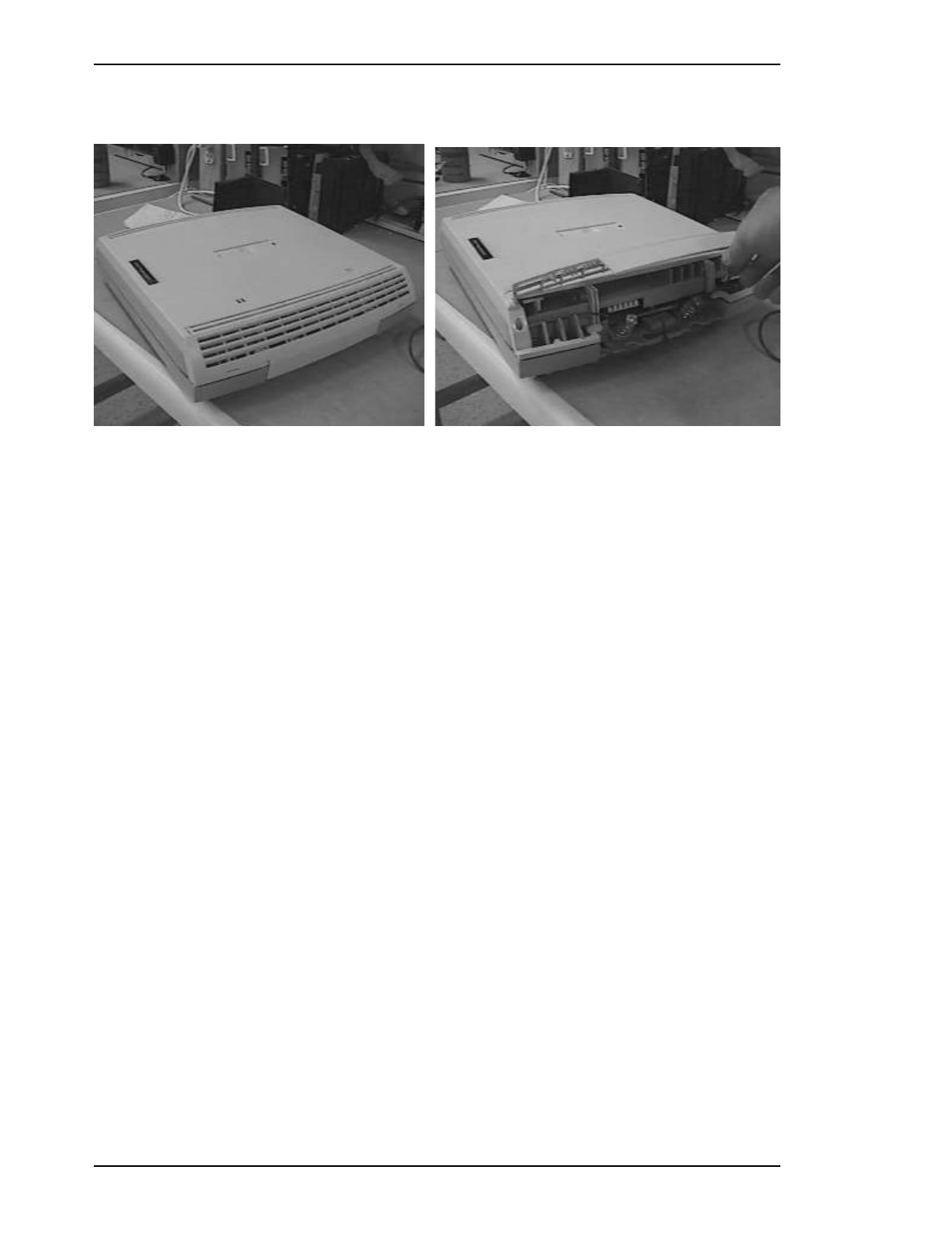
2.2 Tools
The tools listed in Figure 2 are required to perform this method.
2.3 Stock List and Mounting Kits
Table 1 – Tools
U.S. Tool Canadian
Tool Description
Tool Kit Tool Kit Installers Tool Kit
Table 2 – Stock List and Mounting Kits
Quantity CPC/PEC Product Description
1P0880222 PICOCELL 1900 Mounting bracket
1NTMQ7025 PICOCELL Point of Use Power Supply
NTMQ40AA Picocell Basestation, 1900MHz A Band
NTMQ50AA Picocell Basestation, 1900MHz B Band
NTMQ60AA Picocell Basestation, 1900MHz C Band
NTMQ70AA Picocell Basestation, 1900MHz 60MHz Band
NTMQ75AA Picocell Basestation, 1900MHz 60MHz Band
Table 3 – Mounting Hardware
Quantity CPC/PEC Product Description
10 / Picocell 1900 Radio Unit Installation
Method 02-0245 September 3, 1998
Draft
Figure 2 – PICOCELL 1900 front view
2.4 Customer Supplied Equipment
1. Building wiring must be installed between each PICOCELL 1900
transceiver location and the equipment location where the CSI is
located. The mounting of each PICOCELL 1900 transceiver is
independent of CSI and MDF which may be installed later.
2. Floor plans indicating PICOCELL 1900 mounting locations and
locations for CSI and MDF
3. Cabling and pair assignment matching PICOCELL 1900 transceivers to
cable pair numbers.
4. Building access authorization, security clearance if required and keys
for access to restricted CSI and PICOCELL 1900 equipment locations.
Picocell 1900 Radio Unit Installation / 11
September 3, 1998 Method 02-0245
Draft
3.0 Precautions and Preparations
3.1 Precautions
Observe the general safety precautions against personal injury and
equipment damage outlined in the ISM/IM0 at all times.
Picocell transcievers may be handled without static protection. Use of
a grounded wrist strap is mandatory when handling all other exposed
circuit packs or modules.
This method is for indoor installations only.
Picocell 1900 transcievers and antennae are for indoor installations only
and mounting of some or all; transcievers, antennas, hybrids and cabling
in an outside environment may create a potential fire hazard from
lightning. Custom design is required to address outdoor requirements.
Avoid thermal trapped air cavities. In particular, the Picocell cannot be
mounted above the ceiling as this is deemed a plenum installation, and
different, tighter safety specifications are enforced.
3.2 Preparations
Prior to starting the operations presented in this method, arrange all
materials, tools, and test equipment at the work location so as to
minimize fatigue and inconvenience.
1. Has an Installation Planning Checklist per IM-0242 been completed?
2. Are System design and site floor plans available with equipment
locations ?
3. Is building wiring installed and accessible?
4. Is all the test equipment necessary to complete the job on site?
5. Is all the PICOCELL transceiver and antenna equipment on site and
inventoried?
6. Is the customer supplied equipment (back boards, MDF blocks) on site
and installed?
7. Has the loadbuild sent all required switch load tapes to the MTX site?
CAUTION
Maintain minimum or greater distances from interference
sources and from equipment and apparatus which may be
affected by RF energy.
12 / Picocell 1900 Radio Unit Installation
Method 02-0245 September 3, 1998
Draft
8. Are System T1s facilities ordered (if required) and what is the
availability date?
9. Is the antenna system design cabling Interconnect Schematic available?
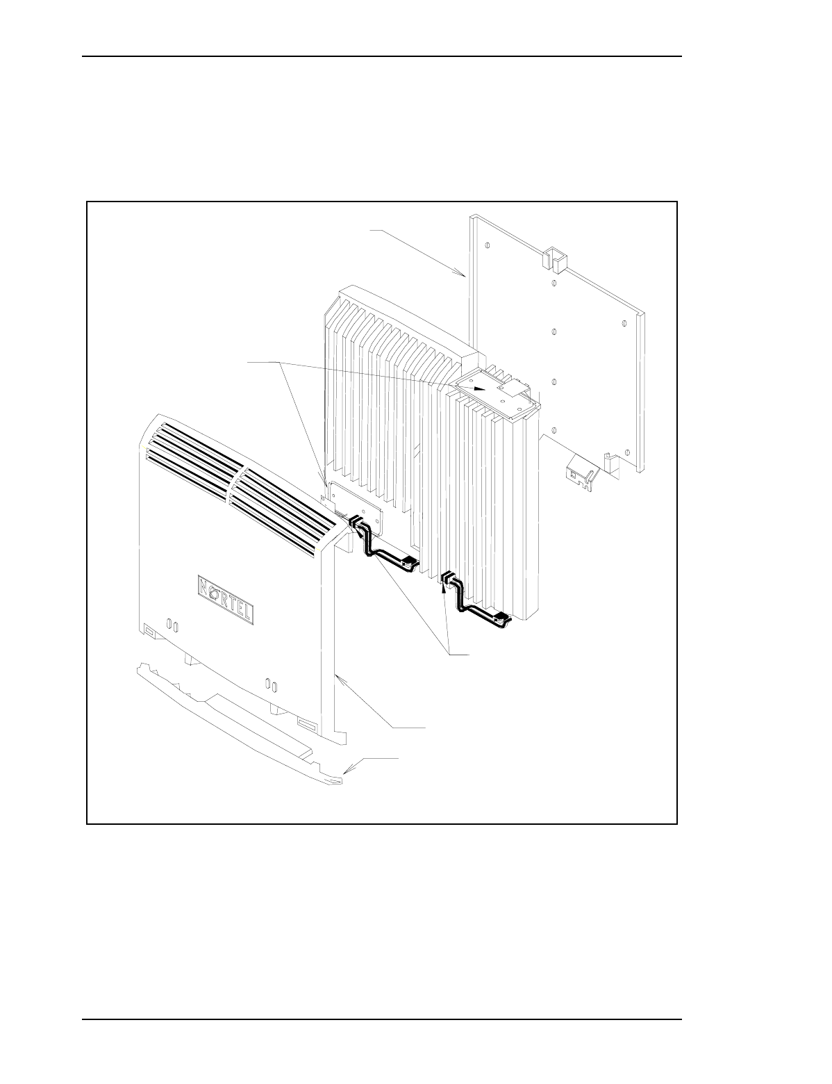
Figure 3 – Transciever Assembly
Interface Cover P0880218
Cover P0880217
P0880211
Antenna
Element
LED indicators
P0880222

Picocell 1900 Radio Unit Installation / 13
September 3, 1998 Method 02-0245
Draft
4.0 Procedure
4.1 Overview
Below is a list of procedures required to install the PICOCELL 1900:
Procedure 1 - Unpacking and Inventory transciever Material
Procedure 2 - Wall Mounting and securing the Radio Mounting Bracket
Procedure 3 - Ceiling Mounting and securing the Radio Mounting
Bracket
Procedure 4 - Installation of PICOCELL Transceiver onto Wall
Mounting Bracket
Procedure 5 - Co-located AC power supply Installation
Procedure 6 - Remote AC power supply Installation

14 / Picocell 1900 Radio Unit Installation
Method 02-0245 September 3, 1998
Draft
.
Procedure 1 – Unpacking and Inventory transciever Material
Step Action Observation
1Inspect the cartons for any damage.
2Refer to Section 2.3 Product Stock List
and Mounting Kits, for a list of parts to
be included in the cartons
Table 2, “Stock List and Mounting Kits,” on
page 9
3Remove all equipment from their cartons
and verify the equipment received is not
damaged. After all of the parts are
removed from the cartons and inspected,
inventory them making sure that all the
parts listed in Section 2.3 are on site.
4Refer to the PICOCELL 1900 Installa-
tion Planning Method 02-0242 and the
System Design Specification to deter-
mine how many CSI and PICOCELL
1900 (PICOCELL 1900 Base Station)
transcievertranscievers are required and
to determine where and how to position
the units.
5Also take into consideration the desired
location of the Hybrid. Due to the length
of the antenna cables, the transceiver(s)
and Hybrid(s) will have to reside close
together. Refer to the PICOCELL 1900
Installation Planning Method 04-0242
and Antenna installation 12-0152 for
spacing requirements and cable length
considerations.

Picocell 1900 Radio Unit Installation / 15
September 3, 1998 Method 02-0245
Draft
..
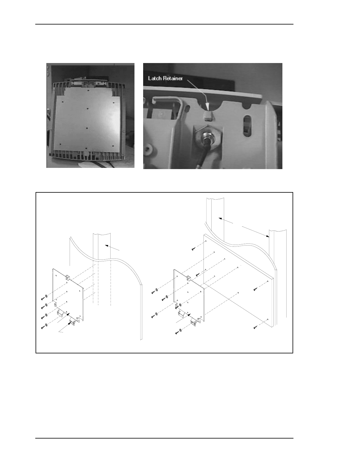
Procedure 2 – Wall Mounting and securing the Radio Mounting Bracket
Step Action Observation
1Locate the wall mounting bracket and
the screws provided. Determine the
required direction transcieverf the wall
mount bracket orientation from the Sys-
tem Design floor plan. Refer also to
Appendix B - Orientation
2Locate the 4 mounting screws with the
mounting bracket . If external antennas
are used, the transcievers and Hybrid(s)
will have to reside close together. Ref-
erence Method 04-0152 for antenna sys-
tem installation.
Figure 4
3Square the bracket with the wall and/or
ceiling and fasten the bracket with the
first screw.
Appendix B
4After one top corner has been fastened
to the wall, check to make sure the wall
mounting bracket is still level before
installing the additional wood screws
5Install the remaining wood screws into
the wall mounting bracket.
Figure 4
6Position the transciever into the bracket
and ensure that the locking retainer is
locked and correctly positioned .
16 / Picocell 1900 Radio Unit Installation
Method 02-0245 September 3, 1998
Draft
Figure 4 – PICOCELL Transceiver Bottom view
Figure 5 – PICOCELL Wall Mount
Backboard
Wall Mount
Wall Studs
Wall Mount
Latch Locking
P0880222
Mounting Bracket Mounting Bracket
P0880222
Wall Stud

Picocell 1900 Radio Unit Installation / 17
September 3, 1998 Method 02-0245
Draft
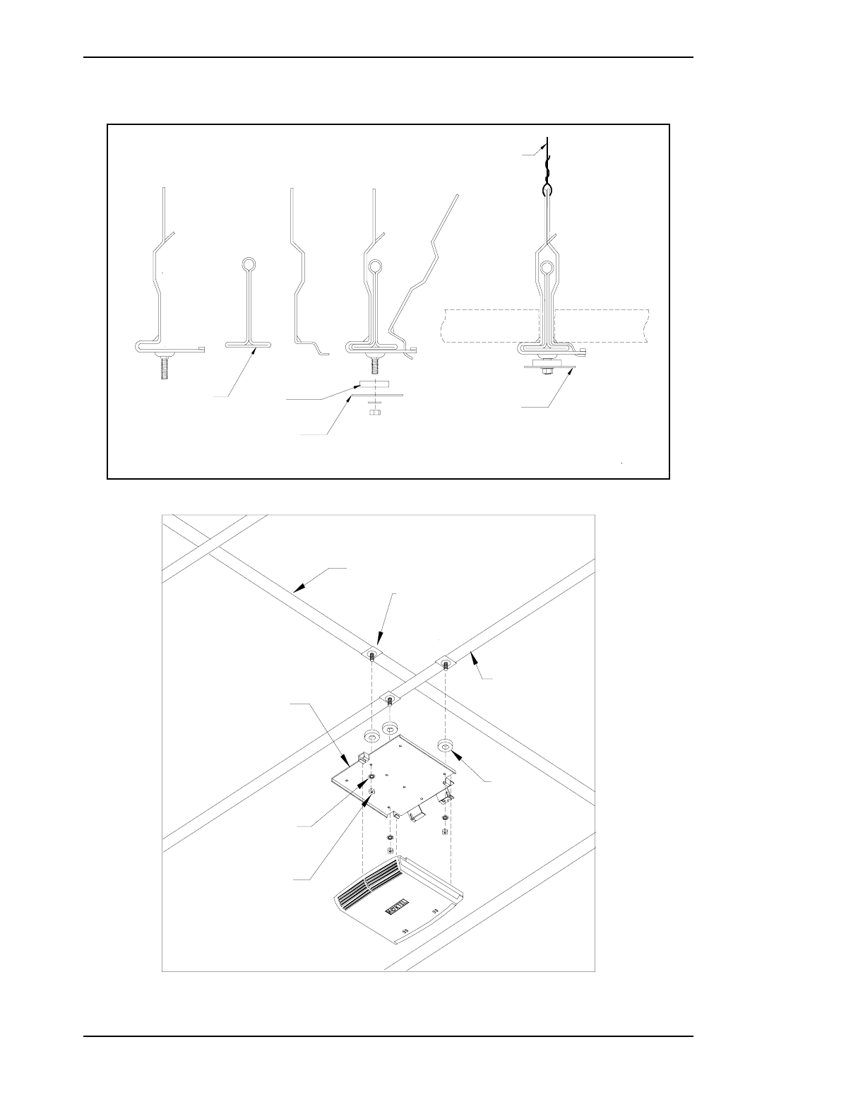
Procedure 3 – Ceiling Mounting and securing the Radio Mounting Bracket
Step Action Observation
1Locate the wall mounting bracket and
the screws provided. Determine the
desired direction of the wall mount
bracket orientation. Refer to the system
layout document to determine readio
orienation.
2 Locate the ceiling main support track
closest to the desired mounting location
and attach the IDS clips as shown in Fig-
ure 6 . If the ceiling track is poorly sup-
ported use drop wire from each IDS clip
to a secure point above the mouning
location in main ceiling. Replace the
ceiling panel
Figure 6
3Attach the mounting bracket to the ceil-
ing as shown in Figure 7 using spacers
between the bracket and the IDS clips.
Note that the nuts on the IDS clips must be flusch
to permit the transciever to lock into the mount-
ing bracket to
Appendix B
4Drill an access hole near the front of the
transciever for the facility cable pairs.
5Lock the transciever into the bracket and
complete the wired connections.
18 / Picocell 1900 Radio Unit Installation
Method 02-0245 September 3, 1998
Draft
Figure 6 – Track Ceiling support IDSClips
Figure 7 – PICOCELL Transciever Ceiling mount
Drop wire
Mouinting
Bracket
Spacer
Ceiling support
Track Mouinting
Bracket
Ceiling Panel Ceiling Panel
Mounting
Bracket
Main Ceiling
Track
Spacer
x3
Nut
x3
Washer
x3
Cross Track
IDS Clip
X3
Picocell 1900 Radio Unit Installation / 19
September 3, 1998 Method 02-0245
Draft
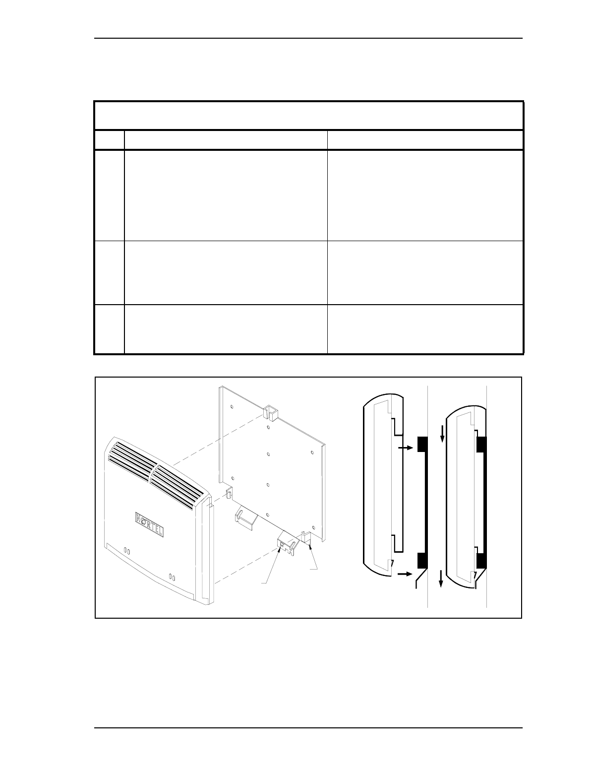
Figure 8 – Locking the transciever into the mounting Bracket
Procedure 4 – Installation of PICOCELL Transceiver onto Wall Mounting Bracket
Step Action Observation
1Remove the connector access cover and
position the transciever onto the mount-
ing bracket and slide the unit so that the
radio locks onto the bracket and the
retainer catch engages with the latch
hole.
See Figure 4 and Figure 8
2At this point PICOCELL 1900 wiring
connections can be completed by open-
ing the interface panel cover and making
connections per Figure 12.
3PICOCELL 1900 cabling and commis-
sioning can be completed, proceed with
Method 12-0152 and 04-0244.
P08800222
Mounting Bracket
Radio unit
Locking
Retainer
20 / Picocell 1900 Radio Unit Installation
Method 02-0245 September 3, 1998
Draft
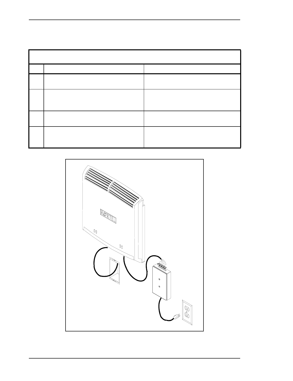
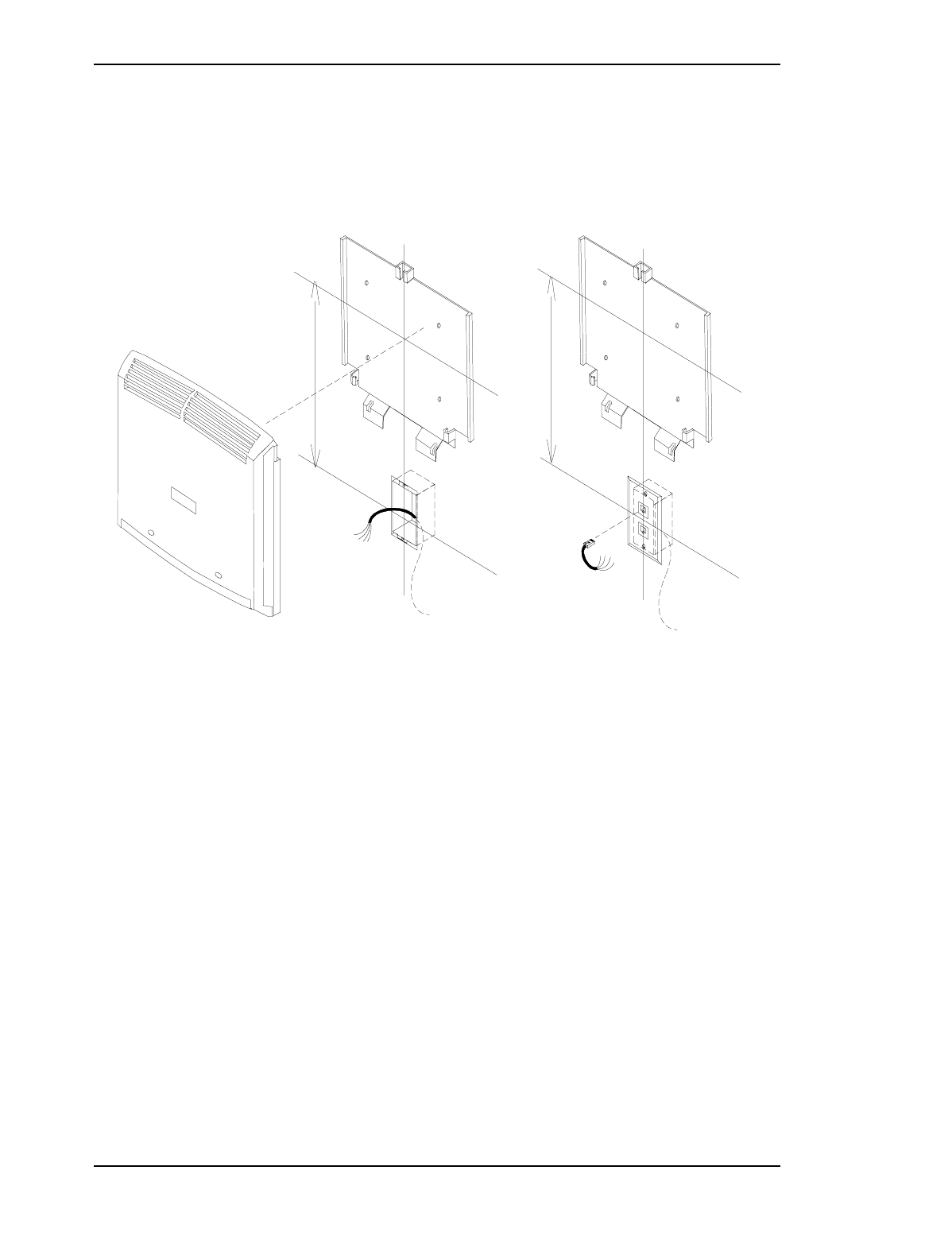
Figure 9 – PICOCELL Co-located power supply
Procedure 5 – Co-located AC power supply Installation
Step Action Observation
Note that an AC outlet must be provided by a
qualified electrician.
1 Locate the AC-DC power supplies and mount as
shown in Figure 9. Coil excess cord and tie back
excess cable with tie wraps.
2 Connect the power supply to the transciever and
terminate power wires as shown on Figure 12
3 Plug the power supply into the AC outlet and
verify the supply output power.
Verify the transciever operation in IM 04-0246
- 48VDC
transciever powers up with activity on LEDs
Picocell 1900 Radio Unit Installation / 21
September 3, 1998 Method 02-0245
Draft
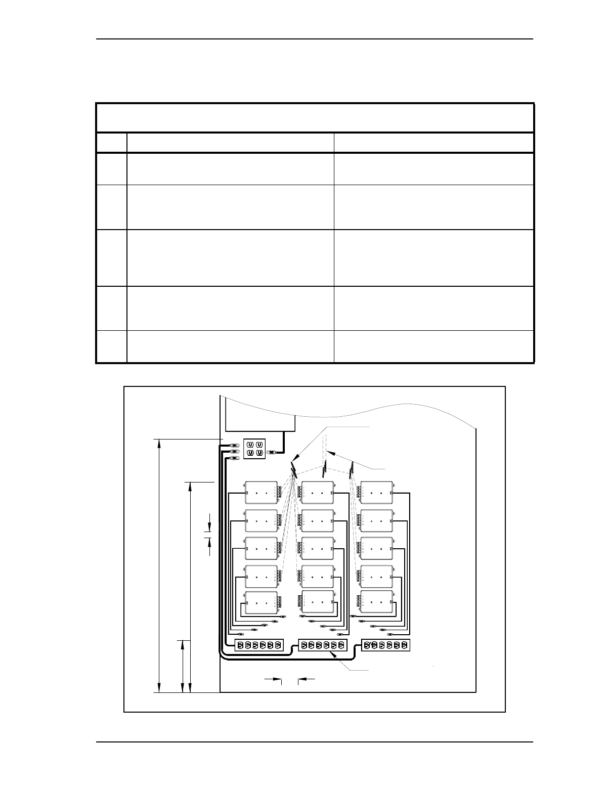
Figure 10 – Remote Power Supply Mounting (Typical)
Procedure 6 – Remote AC power supply Installation
Step Action Observation
Note that AC outlets must be provided by a
qualified electrician. AC outlet placement per IM 04-0241 and Fig-
ure 10.
1 Locate the AC-DC power supplies and mount as
shown in Figure 10. Coil excess cord and tie
back excess cable with tie wraps.
2 Connect the power supply jumpers to the MDF
blocks see IM-04-0244 for jumpers and cabling.
transciever and terminate power wires as shown
on Figure 10
3 Plug the power supply into the AC outlet and
verify the supply output power.
Verify the transciever operation in IM 04-0246
- 48VDC
4 See IM 18-0244 fro cabling and jumpering of DC
power.
AC Power Bars
Jumper Rings
Jumper Routing
45"
AC-DC
-48VDC
AC-DC
-48VDC
AC-DC
-48VDC
AC-DC
-48VDC
AC-DC
-48VDC
AC-DC
-48VDC
37.0"
9.2"
1.0"
AC-DC
-48VDC
AC-DC
-48VDC
AC-DC
-48VDC
3.0"
AC-DC
-48VDC
AC-DC
-48VDC
AC-DC
-48VDC
AC-DC
-48VDC
AC-DC
-48VDC
AC-DC
-48VDC
CSI
110VAC
-48V
22 / Picocell 1900 Radio Unit Installation
Method 02-0245 September 3, 1998
Draft
4.2 Power Supply connections
The PICOCELL 1900 transciever is powered by an AC to -48VDC
supply which is mounted either at the CSI location or near the
PICOCELL transceiver mounting position. If it is mounted near the
transciever (co-located), an AC outlet must also be within close
proximity. When the supply is co-located near the transceiver, the
power wiring may or may not be accommodated in the station wiring
conduit and may need to be dressed neatly on the wall or ceiling surface.
See Figure 9.
See IM 02-0241 for placement, mounting and connection of the power
supply at the remote CSI location.
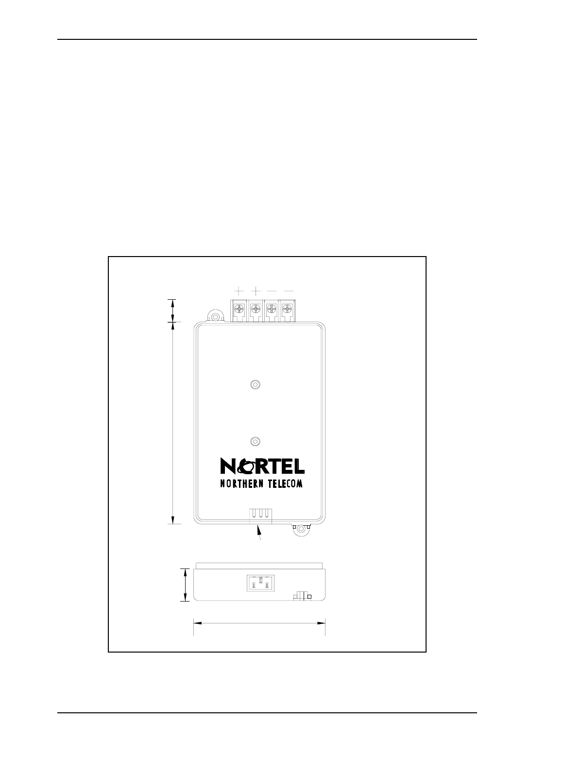
Figure 11 – Power supply and connections
4.0"
1.0"
3 terminal IEC 320 Jack
120VAC
Grd 48V
6.5" 0.7"
Picocell 1900 Radio Unit Installation / 23
September 3, 1998 Method 02-0245
Draft
4.3 PICOCELL Transceiver Connections
Connections to the PICOCELL 1900 transciever consist of bare wire
terminations on the PICOCELL 1900 terminal strip which provides
terminals for the following:
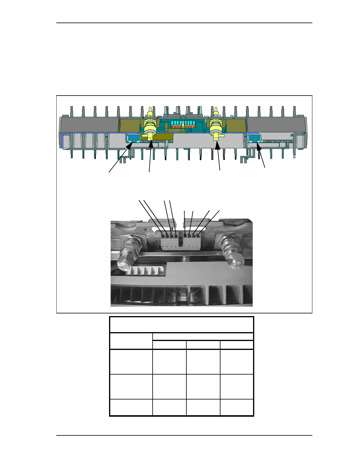
Figure 12 – PICOCELL transciever Connections
Figure 13 – PICOCELL 1900 cabling and connec-
tions
Description
From
Frame Block Pos Pair
TCM 1 T (-) MDF 1 1 T
TCM 1 R (+) MDF 2 1 R
Power - 48V MDF 3 2 T
Power - 48V MDF 4 2 R
TCM 2 T (-) MDF 5 3 T
TCM 2 R (+) MDF 6 3 R
Power + Grd MDF 7 4 T
power+ Grd MDF 8 4 R
Terminal port Radio 1 Terminal Port Radio 2
TX/RX 1 TX/RX 2
-48V +Grd TCM 1
T R
- +
TCM 2
T R
- +

24 / Picocell 1900 Radio Unit Installation
Method 02-0245 September 3, 1998
Draft
5.0 References
Document Number Title
IM 04-0241 PICOCELL 1900 CSI Installation and Planning
IM 04-0242 PICOCELL 1900 General Information and Plannng
IM 08-0243 PICOCELL 1900 CSI Equipment Handling and Securing
IM 04-0244 PICOCELL 1900 System Cabling and Cross Connect
IM 12-0152 PICOCELL 1900 Antenna System Installation
IM 02-0245 PICOCELL 1900 transciever Installation
IM 22-0246 PICOCELL 1900 Radio and CSI Power up
IM 24-0247 PICOCELL 1900 Equipment Loading and Diagnostics
IM 28-0248 PICOCELL 1900 Radio Commissioning with the IFR 1900
IM 28-0249 PICOCELL 1900 System Test
Picocell 1900 Radio Unit Installation / 25
September 3, 1998 Method 02-0245
Draft
6.0 Appendices
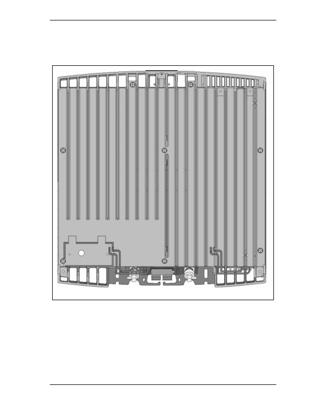
Appendix A - PICOCELL 1900 transciever Cover removed Top view
26 / Picocell 1900 Radio Unit Installation
Method 02-0245 September 3, 1998
Draft
Appendix B - Mounting Orientation and Isolation
Arrangement B
x
x
P0880222
Mounting Bracket
Arrangement A
P0880222
Mounting Bracket
Wall or Ceiling outlet box Wire entrance
Wire entrance
P0880222
Mounting Bracket
P0880222
Mounting Bracket
Note: Ensure station wiring does not loop or coil
near the PICOCELL 1900 antenna. The unit
installation should mount as shown with
maximum spacing between the antenna and
entrance wiring to avoid interference with RF
signals.

Picocell 1900 Radio Unit Installation / 27
September 3, 1998 Method 02-0245
Draft
Appendix C - Picocell 1900 Technical Specifications
• Maxcimum length twisted pair distribution, 3000’ (TCM)
• Maximum length remote Power (see IM 04-0242 section 4.2)
• 1900MHz Version IS 136 TDMA operation
• 100mW (+20dBm) ERP
• 2 RF channels per PICOCELL 1900 RF unit (Internal duplexer)
• Internal Omni Antenna
• Receiver Diversity
• Distributed Omni and directional Antenna Support
• 4 twisted pair per unit for power and digital link (TCM)
• 48 Volt DC power 32W nominal
• Visually pleasing, non-obtrusive design
• Individual transciever Alarms
• 15 PICOCELL 1900s per CSI (30 RF channels)
• Standard Nortel TRU maintenance interface.
• 12.8" W x 13.6" L x 3.25" D
• 14 lb unit weight
AC REQUIREMENTS
Each non-switched dedicated outlet must have the following:
• Voltage110 - 120 VAC
• Frequency47Hz to 53Hz or 57 Hz to 63 Hz
• Power (I/P max)300 VA
• Receptacles-120V 15A service NEMA IG 5-15R
• -208/240V 15A service NEMA IG 6 15R
• Warnings for AC power cord:
Note: See local electrical codes for 240VAC outlet requirements
WARNING
The socket-outlet shall be installed near the equipment and shall be
easily accessible. Power cords are 6ft maximum.

28 / Picocell 1900 Radio Unit Installation
Method 02-0245 September 3, 1998
Draft
Picocell 1900 Power Supply Specifications
Input
• Voltage: 120/240 VAC Nominal
• Line Frequency 50/60 Hz Nominal
• Power rating 90W
• Protection Internal primary current fuse, Inrush limiting
• Configuration In Case IEC320 with Ground
• 6 ft., 5 Conductor, 18 AWG,
Output
• Voltage -48VDC +/- .5V
• Nominal current 2.0 A Max.
• Combined Line and Load Voltage Regulation
• output current limiting
• Short circuit protection
Mechanical
• 6.58 L x 4.0 W x 1.25 H(in)
• Case Material: Black 94V0 Polycarbonate
• Weight: 22 ounces, 625 grams (excluding cords)
Last Page