Avaya Canada NTTG90AA User Manual 411 6201 500P0303
Avaya Canada Corporation 411 6201 500P0303
UserManual.wiki
>
Avaya Canada
>
NTTG90AA User Manual
User manual
Navigation menu
Upload a User Manual
Namespaces
Wiki Guide
HTML
PDF
Info
Views
User Manual
Discussion / Help
Navigation


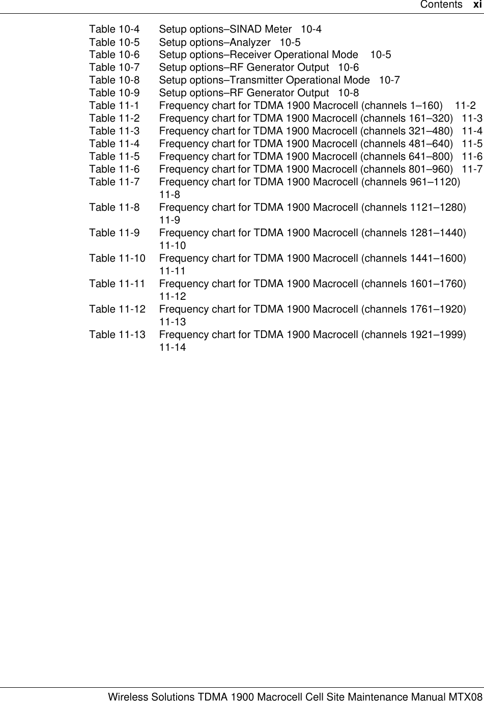

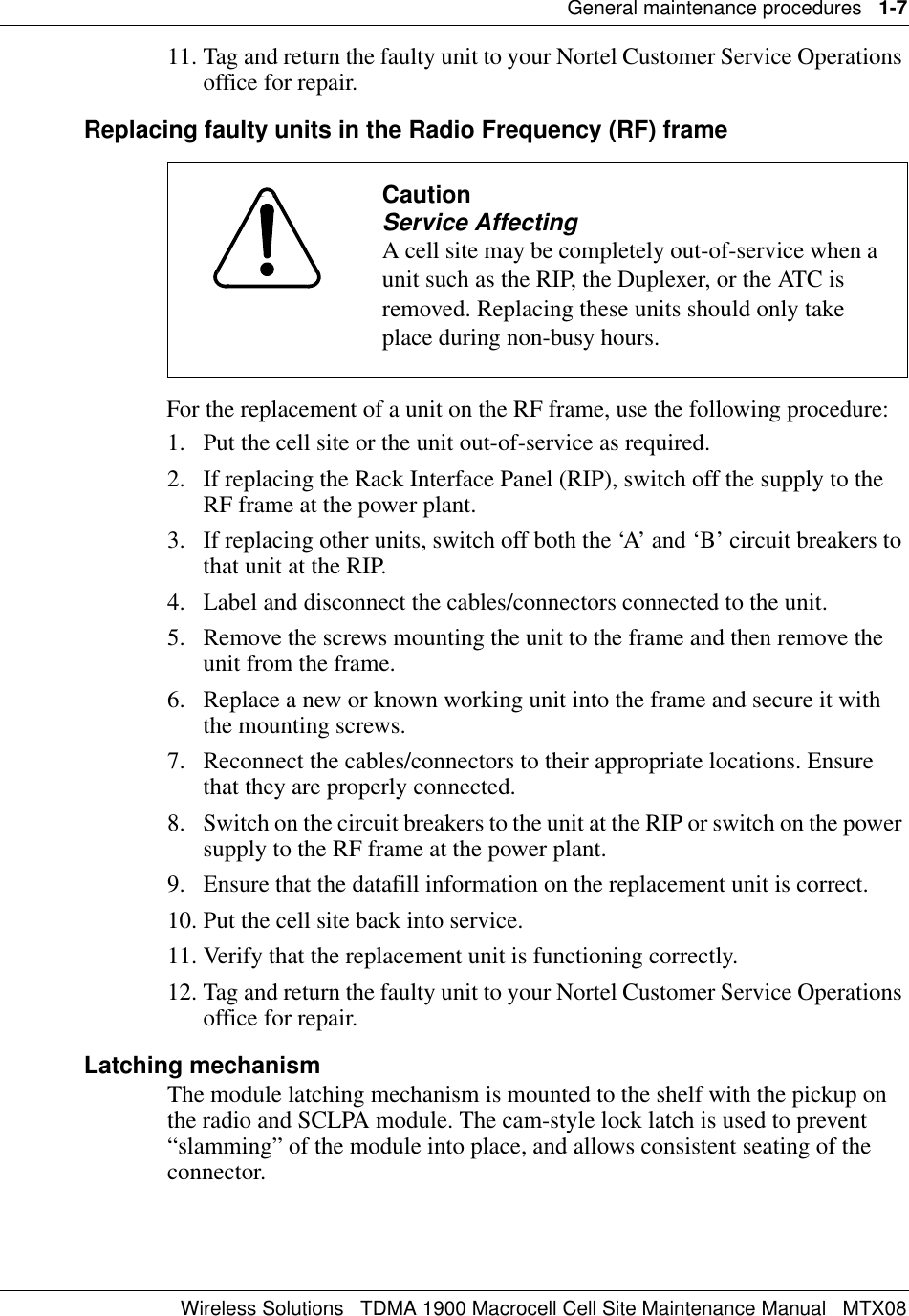

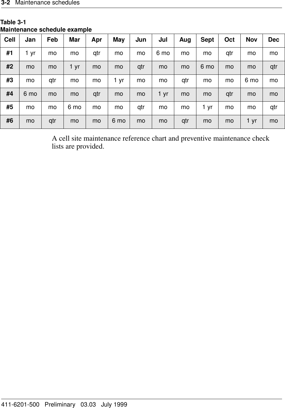


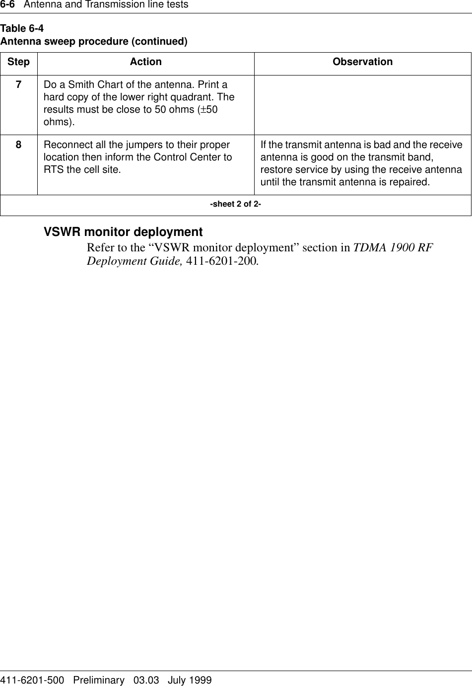
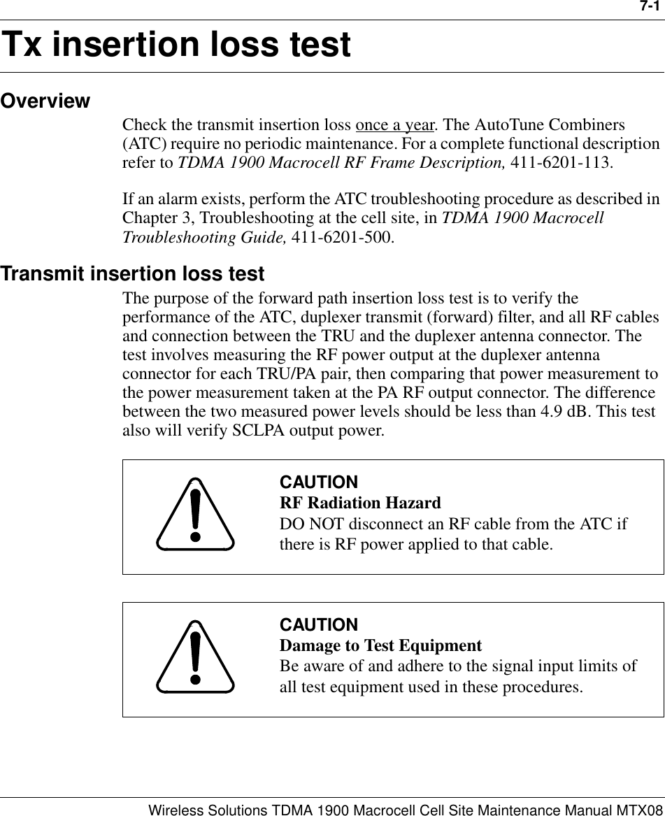
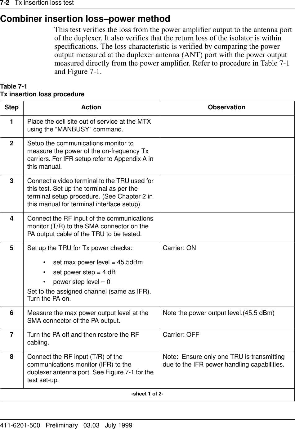
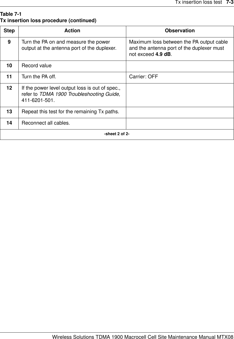
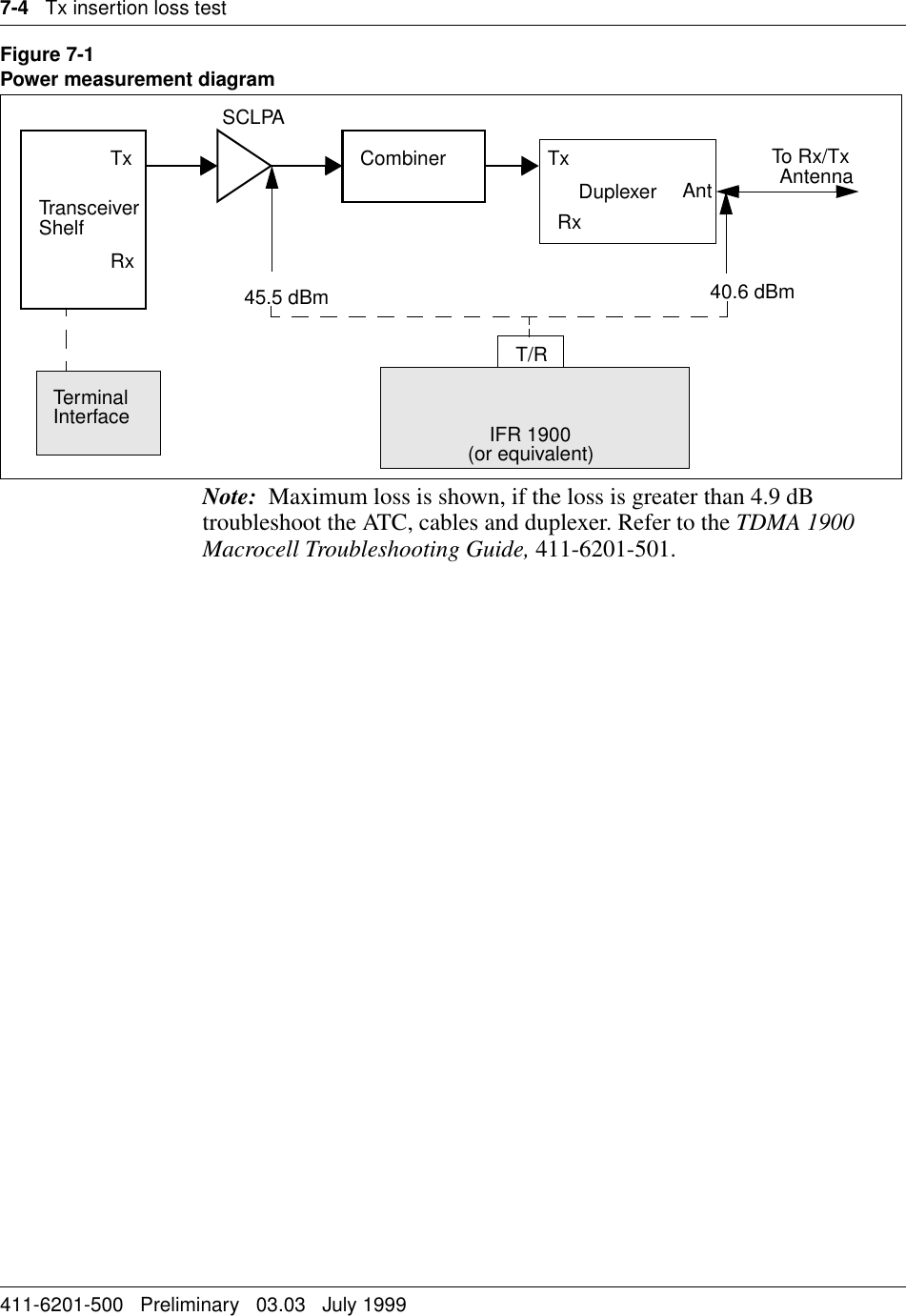
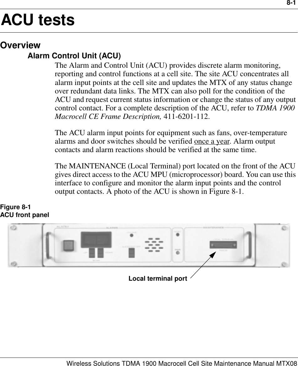
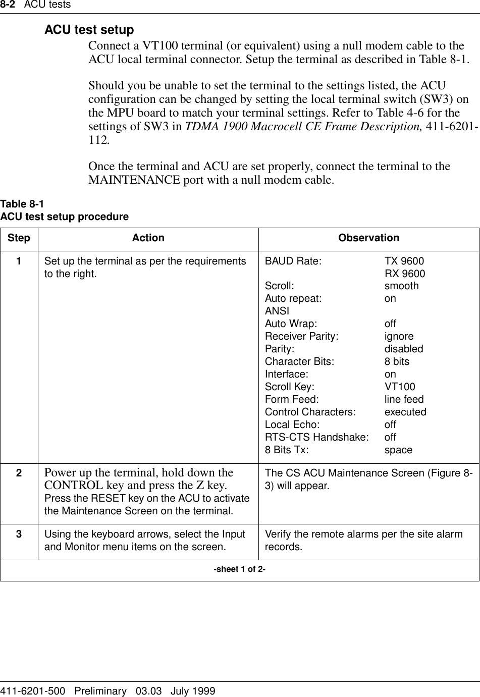
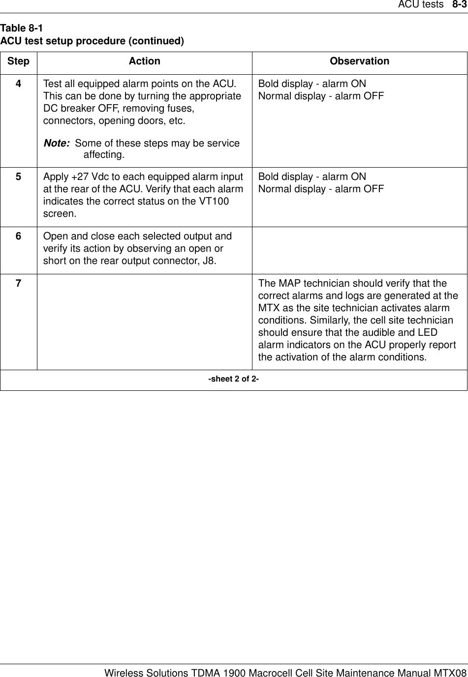
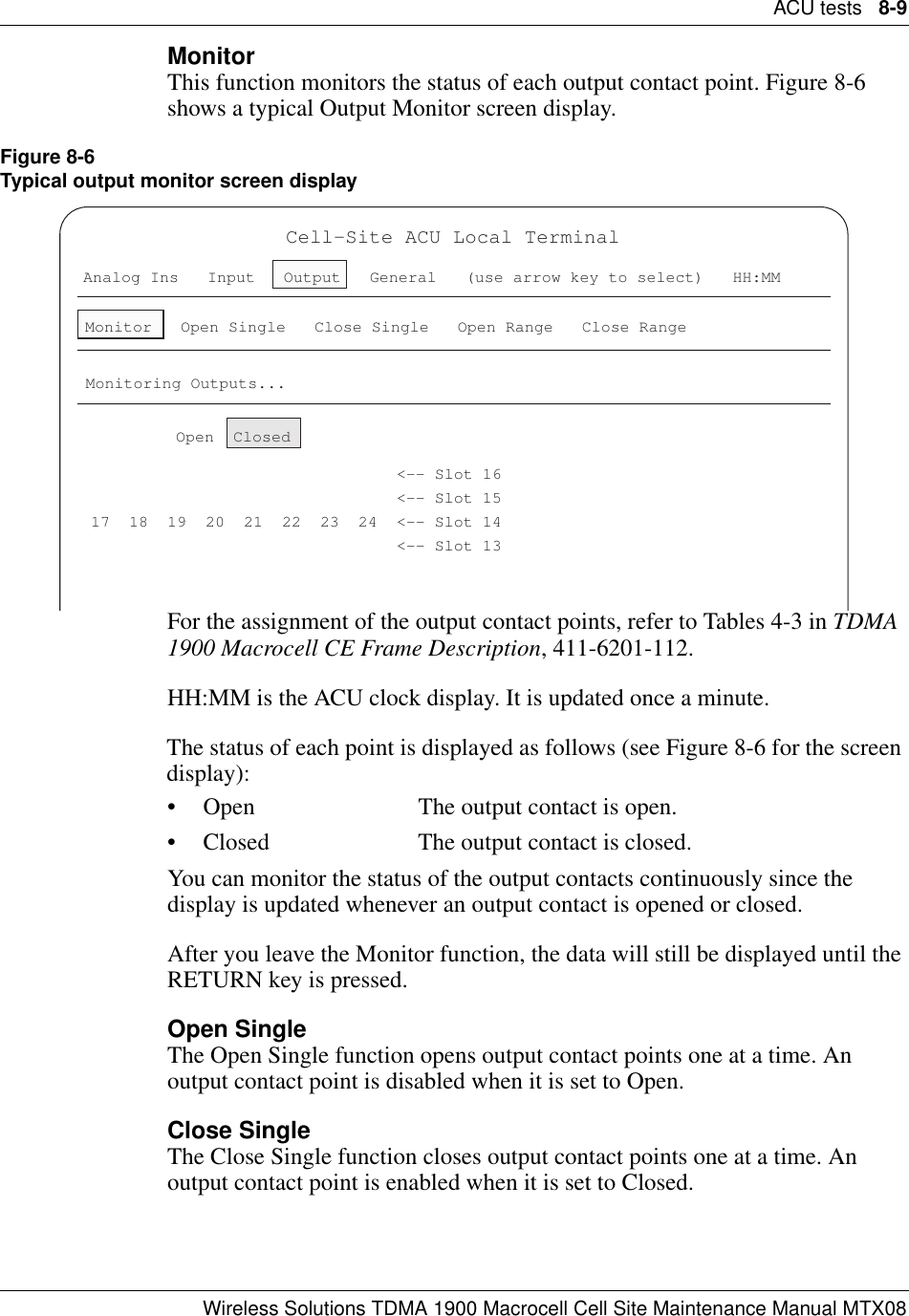
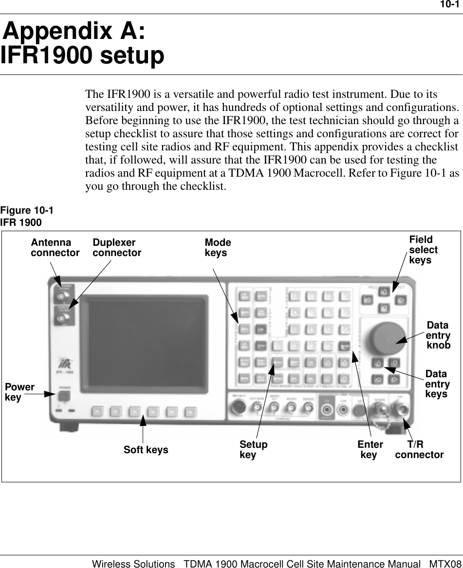
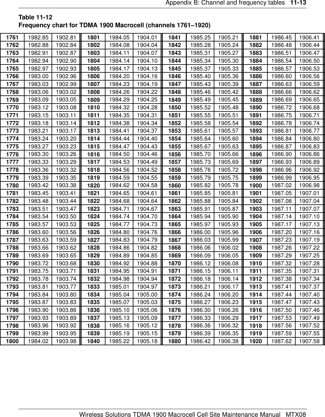
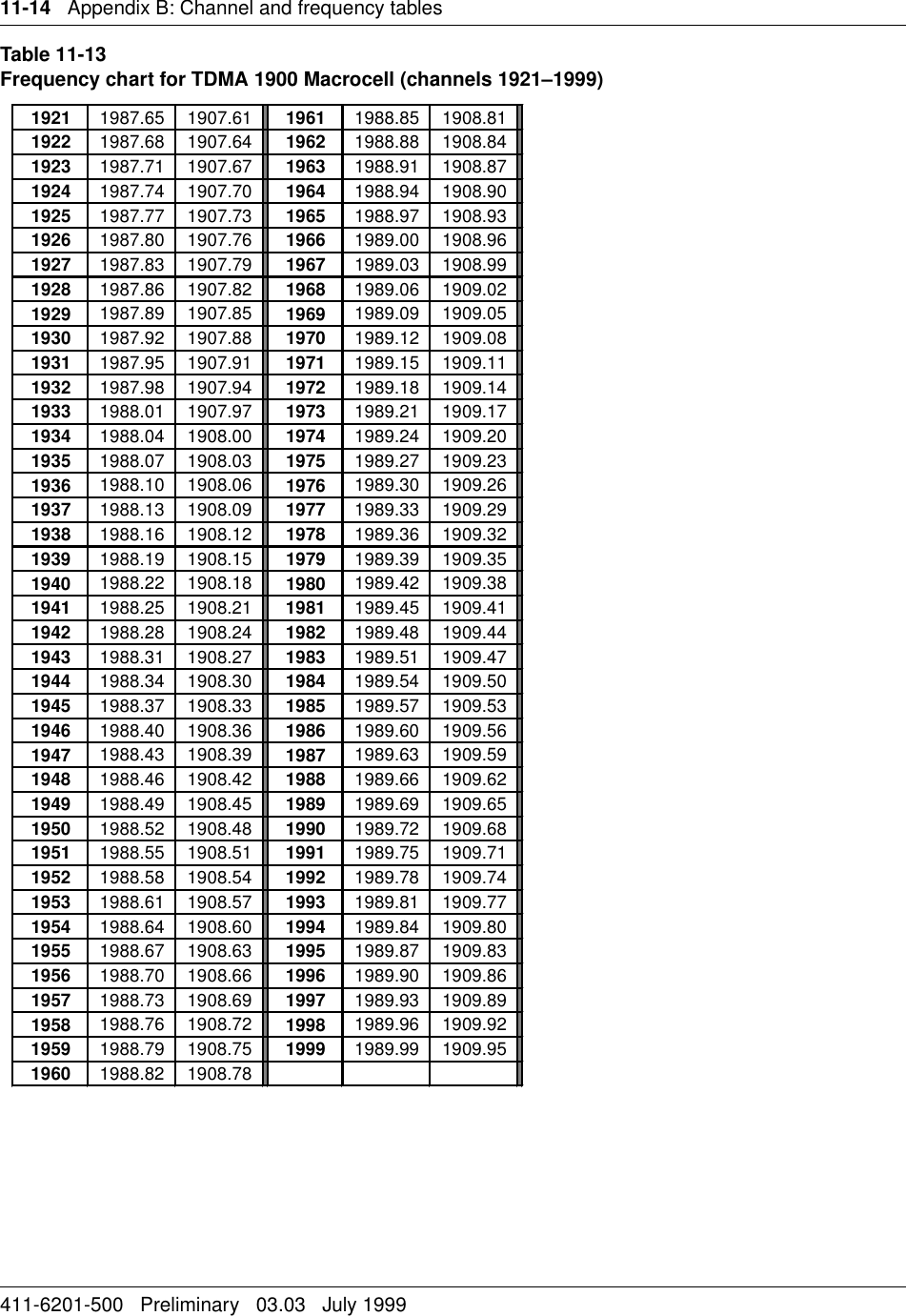
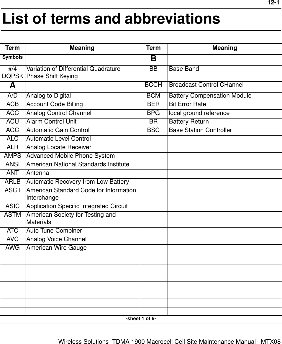
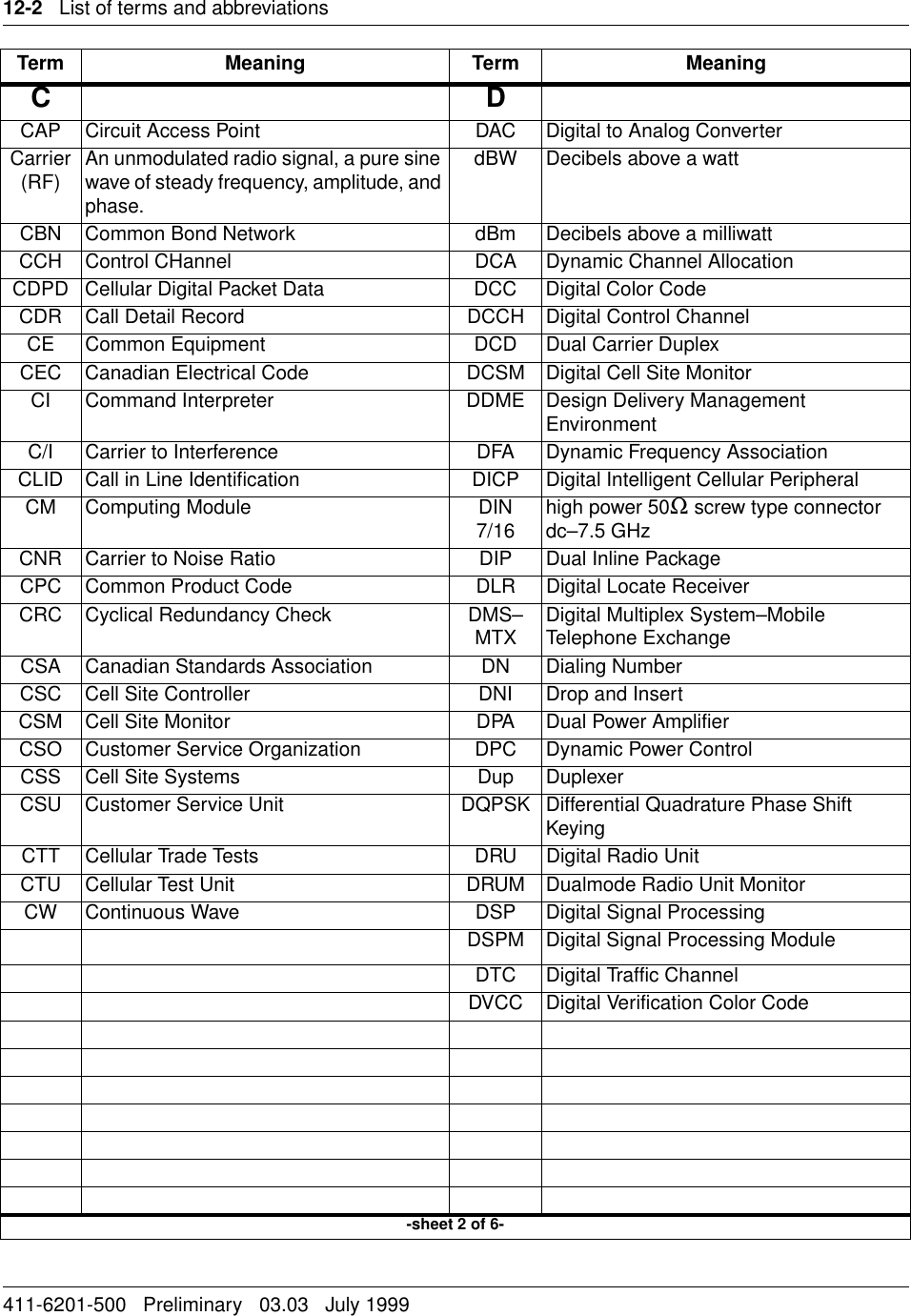
![8-10 ACU tests411-6201-500 Preliminary 03.03 July 1999Open RangeThe Open Range function opens a group of output contact points at a time.Close RangeThe Close Range function closes a group of output contact points at a time.General optionThree functions can be selected under the General option.•Set Clock•Restart• Show Function CodesFirmware Info.Set ClockThe ACU clock determines the time alarms are generated. You can set the time on a 24-hour basis by using this option. From the map terminal at the MTX.RestartThis function restores the alarm input points and output contacts of the ACU to the default states.Show Function CodesThis function displays the function codes the system uses on messages between the MTX and the ACU.ACU front panel displayA red four digit LED display indicates the status of the input points. Only alarms from enabled inputs will be reported; a disabled Input will not alarm. The display shows the Input point by the number of the last active alarm. For example, a flashing [167] indicates that Input point #167 -RRMX ALARM- is active (in alarm state). The display will flash until acknowledged by pressing either the UP or DOWN button. All the active alarm points can then be scrolled with the UP and DOWN buttons. When an Input point returns to the inactive (normal) state, the Input point number will no longer be displayed. Inactive or disabled input points do not display on the front panel. An Input point is enabled or disabled from the local terminal or DMS–MTX interface. Similarly, status of the output contacts can only be obtained from either the local terminal or DMS–MTX interface.Audible alarmA Sonalert type of audible indication is provided at the ACU. This alert sounds on every new alarm, and continues until silenced by the operator.](https://usermanual.wiki/Avaya-Canada/NTTG90AA/User-Guide-50822-Page-94.png)