Avaya Canada NTTG90AA User Manual 411 6201 500P0303
Avaya Canada Corporation 411 6201 500P0303
User manual

Wireless Solutions
TDMA 1900 Macrocell
Cell Site Maintenance Manual
MTX08 Preliminary 03.03 July 1999
411-6201-500


Wireless Solutions
TDMA 1900 Macrocell
Cell Site Maintenance Manual
Product release: MTX08
Document release: Preliminary 03.03
Date: July 1999
Document Number: 411-6201-500
Copyright Country of printing Confidentiality Legal statements Trademarks
1999 Northern Telecom
Printed in Canada
NORTHERN TELECOM CONFIDENTIAL: The information contained in this document is the property of Northern
Telecom. Except as specifically authorized in writing by Northern Telecom, the holder of this document shall keep the information
contained herein confidential and shall protect same in whole or in part from disclosure and dissemination to third parties and use
same for evaluation, operation, and maintenance purposes only.
Information is subject to change without notice.
DMS, DMS/MTX, MAP and NORTEL are trademarks of Nortel Networks.

iv
411-6201-500 Preliminary 03.03 July 1999

v
Wireless Solutions TDMA 1900 Macrocell Cell Site Maintenance Manual MTX08
Publication history
July, 1999 (Preliminary 03.03)
Added the TRU3 1900 to the document for internal review.
May, 1999 (Standard 03.02)
Updated to release for MTX08 Standard CD.
February, 1999 (Preliminary 03.01)
Updated to release for MTX08 Preliminary CD.
August, 1998 (Standard 02.01)
Updated document content and styles
March, 1998 (Preliminary 01.01)
Up-issue for MTX07 release
Feb, 1998 (Draft 00.03)
Updated release for G2
Dec, 1997 (Draft 00.02)
Updated release of this document for team review
Nov, 1997 (Draft 00.01)
The initial publication of this document

vi
411-6201-500 Preliminary 03.03 July 1999

vii
Wireless Solutions TDMA 1900 Macrocell Cell Site Maintenance Manual MTX08
Contents
About this document xiii
Audience for this publication xiii
How this publication is organized xiv
General maintenance procedures 1-1
General precautions 1-1
RF radiation hazard 1-1
Cable/connector identification 1-1
Electrostatic Discharge (ESD) 1-1
ElectroStatic Discharge (ESD) control 1-2
Field Replaceable Units (FRU’s) 1-6
Replacing faulty units in the Common Equipment (CE) frame 1-6
Replacing faulty units in the Radio Frequency (RF) frame 1-7
Latching mechanism 1-7
Product structure for a TDMA 1900 Macrocell cell site 1-8
Customer Service Operations (CSO) 1-15
Test equipment 2-1
Precautions 2-1
Test equipment 2-2
Terminal interface operation 2-3
Introduction 2-3
Interfacing the terminal with the TRU 2-5
Terminal interface command line mode 2-14
Measurement commands 2-18
Test commands 2-20
Maintenance schedules 3-1
Periodic maintenance records 3-1
Manuals and records 3-1
Schedule for periodic cell site maintenance 3-1
TDMA 1900 Macrocell cell site maintenance reference chart 3-3
TDMA 1900 Macrocell cell site EVERY VISIT checklist 3-5
TDMA 1900 Macrocell cell site MONTHLY checklist 3-6
TDMA 1900 Macrocell cell site QUARTERLY checklist 3-7
TDMA 1900 Macrocell cell site SEMI-ANNUAL checklist 3-7
TDMA 1900 Macrocell cell site ANNUAL checklist 3-8

viii Contents
411-6201-500 Preliminary 03.03 July 1999
CE and RF frames 4-1
CE and RF frames 4-1
Breakers 4-2
Fans and fuses 4-3
LED checklist 4-3
Dc power inspection 4-4
Frame and equipment voltage checks 4-5
Very Stable Master Oscillator (VSMO) tests 5-1
Very Stable Master Oscillator (VSMO) 5-1
Master Oscillator power and frequency test 5-1
Antenna and Transmission line tests 6-1
Antenna direct current continuity 6-1
Antenna return loss 6-2
Antenna return loss test 6-3
Thruline Wattmeter method (antenna return loss) 6-4
Antenna sweep 6-5
VSWR monitor deployment 6-6
Tx insertion loss test 7-1
Overview 7-1
Transmit insertion loss test 7-1
Combiner insertion loss–power method 7-2
ACU tests 8-1
Overview 8-1
Alarm Control Unit (ACU) 8-1
ACU test setup 8-2
Using the ACU maintenance terminal 8-4
Selecting an option 8-5
Input option 8-6
Output option 8-8
General option 8-10
ACU front panel display 8-10
Miscellaneous equipment tests 9-1
RRM (Remote Receive Module) 9-1
LRM (Local Receiver Module) 9-1
RPDU (Receive Power Distribution Unit) 9-1
ICRM (Intergrated Cellular Remote Module) 9-1
Other equipment 9-1
Transmission facilities 9-2
Microwave 9-2
Copper Audio Link 9-2
Power 9-2
Acid safety equipment 9-2
Battery 9-2

Contents ix
Wireless Solutions TDMA 1900 Macrocell Cell Site Maintenance Manual MTX08
Rectifiers 9-3
Main generators 9-3
Backup generators 9-3
Building service 9-3
Cabling and connections 9-3
Inside grounding 9-4
Frame bonding 9-4
Ground cabling 9-4
Transmission line entrance 9-4
Outside grounding 9-5
Tower and associated structures 9-5
Building sheath, fences and other equipment 9-5
Antennas and tower 9-5
General structure 9-5
Antennas 9-6
Pressurized transmission lines 9-6
Site performance 9-6
Fringe coverage 9-7
Handoff checks 9-7
Housekeeping 9-7
Security 9-7
Heating/air conditioning 9-7
Dust control 9-7
Trash and loose articles 9-8
Site groundskeeping 9-8
Administration 9-8
Statutory requirements 9-8
Site licenses 9-8
Appendix A:
IFR1900 setup 10-1
IFR setup checklist: 10-2
Appendix B:
Channel and frequency tables 11-1
Channel numbering for 1900Mhz spectrum 11-1
PCS frequency sub-bands 11-1
List of terms 12-1
Figures
Figure 2-1 TRU front panel 2-4
Figure 2-2 TRU Fullscreen display 2-7
Figure 4-1 Typical cell site frame layout 4-1
Figure 4-2 CE frame RIP panel layout 4-2
Figure 4-3 RF frame RIP panel layout 4-2
Figure 4-4 Power connector on ACU backplane. 4-5
Figure 5-1 Oscillator power level and frequency test setup 5-2
Figure 6-1 Antenna return loss block diagram 6-3

xContents
411-6201-500 Preliminary 03.03 July 1999
Figure 7-1 Power measurement diagram 7-4
Figure 8-1 ACU front panel 8-1
Figure 8-2 Typical alarm connector (36-pin) 8-4
Figure 8-3 Initial screen display 8-4
Figure 8-4 ACU menu structure 8-5
Figure 8-5 Typical input monitor screen display 8-7
Figure 8-6 Typical output monitor screen display 8-9
Figure 10-1 IFR 1900 10-1
Tables
Table 1-1 Major components of a TDMA 1900 Macrocell cell site 1-8
Table 1-2 Nortel CSO centers 1-15
Table 2-1 Terminal interface connector pinouts 2-4
Table 2-2 Fullscreen command summary 2-9
Table 2-3 Fullscreen commands for configuration functions 2-10
Table 2-4 Fullscreen commands for transmit functions 2-11
Table 2-5 Fullscreen commands for receive functions 2-12
Table 2-6 Fullscreen commands for AMPS mode functions 2-13
Table 2-7 Fullscreen commands for TDMA mode functions 2-14
Table 2-8 Command line maintenance commands 2-15
Table 2-9 Command line measurement commands 2-18
Table 2-10 Command line test commands 2-20
Table 3-1 Maintenance schedule example 3-2
Table 3-2 Cell site maintenance reference chart 3-3
Table 3-3 Cell site EVERY VISIT checklist 3-5
Table 3-4 Cell site MONTHLY checklist 3-6
Table 3-5 Cell site QUARTERLY checklist 3-7
Table 3-6 Cell site SEMI-ANNUAL checklist 3-7
Table 3-7 Cell site ANNUAL checklist 3-8
Table 4-1 LED status checklist 4-3
Table 4-2 Dc power inspection 4-4
Table 4-3 Minimum bending radii of power cables 4-4
Table 4-4 Frame voltage procedure 4-5
Table 4-5 VSMO input power connector (P3) signals 4-6
Table 4-6 RPDU power connector (J2) (6-pin Mate’n lock) 4-6
Table 4-7 RRM power connector on the RPDU (J9) (12-pin Mate’n lock) 4-6
Table 4-8 LRM fan module (J10) (10-pin ribbon) on the RPDU 4-7
Table 4-9 LRM (J3) power connector 4-7
Table 4-10 ICRM power connector 4-7
Table 5-1 VSMO test procedures 5-1
Table 5-2 IFR set up for VSMO test 5-3
Table 6-1 Direct current continuity test 6-2
Table 6-2 Antenna return loss test procedure 6-3
Table 6-3 Thruline wattmeter method 6-4
Table 6-4 Antenna sweep procedure 6-5
Table 7-1 Tx insertion loss procedure 7-2
Table 8-1 ACU test setup procedure 8-2
Table 10-1 Setup options–Frequency Meter 10-2
Table 10-2 Setup options–Power Meter 10-3
Table 10-3 Setup options–Deviation Meter 10-3

Contents xi
Wireless Solutions TDMA 1900 Macrocell Cell Site Maintenance Manual MTX08
Table 10-4 Setup options–SINAD Meter 10-4
Table 10-5 Setup options–Analyzer 10-5
Table 10-6 Setup options–Receiver Operational Mode 10-5
Table 10-7 Setup options–RF Generator Output 10-6
Table 10-8 Setup options–Transmitter Operational Mode 10-7
Table 10-9 Setup options–RF Generator Output 10-8
Table 11-1 Frequency chart for TDMA 1900 Macrocell (channels 1–160) 11-2
Table 11-2 Frequency chart for TDMA 1900 Macrocell (channels 161–320) 11-3
Table 11-3 Frequency chart for TDMA 1900 Macrocell (channels 321–480) 11-4
Table 11-4 Frequency chart for TDMA 1900 Macrocell (channels 481–640) 11-5
Table 11-5 Frequency chart for TDMA 1900 Macrocell (channels 641–800) 11-6
Table 11-6 Frequency chart for TDMA 1900 Macrocell (channels 801–960) 11-7
Table 11-7 Frequency chart for TDMA 1900 Macrocell (channels 961–1120)
11-8
Table 11-8 Frequency chart for TDMA 1900 Macrocell (channels 1121–1280)
11-9
Table 11-9 Frequency chart for TDMA 1900 Macrocell (channels 1281–1440)
11-10
Table 11-10 Frequency chart for TDMA 1900 Macrocell (channels 1441–1600)
11-11
Table 11-11 Frequency chart for TDMA 1900 Macrocell (channels 1601–1760)
11-12
Table 11-12 Frequency chart for TDMA 1900 Macrocell (channels 1761–1920)
11-13
Table 11-13 Frequency chart for TDMA 1900 Macrocell (channels 1921–1999)
11-14

xii Contents
411-6201-500 Preliminary 03.03 July 1999

xiii
Wireless Solutions TDMA 1900 Macrocell Cell Site Maintenance Manual MTX08
About this document
This document is one of a suite of documents that provide Nortel customers
with information and suggestions on the planning, operations and
maintenance of their TDMA 1900 Macrocell system. This documentation
suite includes the documents in the following table:
Audience for this publication
The audience for this set of manuals includes cell site technicians and
planning engineers who require detailed information on the planning,
operation and maintenance of a TDMA 1900 Macrocell cell site.
Document title NTP#
TDMA 1900 Macrocell Master Index of Publications 411-6201-001
TDMA 1900 Macrocell Cell Site Functional Description
(includes the following five documents)
411-6201-100
TDMA 1900 Macrocell Cell Site Description 411-6201-111
TDMA 1900 Macrocell CE Frame Description 411-6201-112
TDMA 1900 Macrocell RF Frame Description 411-6201-113
TDMA 1900 Macrocell Enclosure Description 411-6201-114
TDMA 1900 Macrocell Pre-Installation Guidelines 411-6201-115
TDMA 1900 Macrocell Cell Site RF Deployment Guide 411-6201-200
TDMA 1900 Macrocell Cell Site Installation Methods 411-6201-201
TDMA 1900 Macrocell Cell Site Maintenance Manual 411-6201-500
TDMA 1900 Macrocell Cell Site Troubleshooting Guide 411-6201-501
1

xiv
411-6201-500 Preliminary 03.03 July 1999
The TDMA 1900 Macrocell Functional Description is a technical reference
foundation for the other documents in the documentation suite and is written
for all individuals.
The TDMA 1900 Macrocell RF Deployment Guide and TDMA 1900
Macrocell Installation Methods are written for system planning personnel
planning to implement new cells or expand existing cell sites.
The TDMA 1900 Macrocell Maintenance Manual and the TDMA 1900
Macrocell Troubleshooting Guidelines provide information on problem
recognition and preventive maintenance are written for the cell site technician
to assist in troubleshooting and performing routine work.
The document suite assumes that the reader has a basic knowledge of cellular
systems and radio propagation and is familiar with measurement units and
terms associated with these concepts. This document does not provide
detailed information on the theory of switching and radio propagation.
How this publication is organized
This publication is organized to present the following information:
• TDMA 1900 Macrocell cell site general maintenance procedures
• Equipment needed for the TDMA 1900 Macrocell cell site maintenance
processes
• TDMA 1900 Macrocell maintenance schedules
• Cell site equipment maintenance procedures
1
1-1
Wireless Solutions TDMA 1900 Macrocell Cell Site Maintenance Manual MTX08
1General maintenance procedures
General precautions
There are some general precautions to be aware of when preforming
maintenance on cell site components. When performing maintenance
functions, take care not to do anything which would inadvertently take the site
off the air (make the site drop phone calls in progress). The technician should
always have a clear idea of the action being undertaken, and what is the
potential impact and safety implications of the action on the operating
condition of the network.
RF radiation hazard
Radio Frequency (RF) radiation can be hazardous to anyone working in the
cell site. Before removing any RF cable, ensure that the transmitters are
turned off. All RF cables should be connected properly and all unused RF
ports should be terminated with an appropriate terminator.
Cable/connector identification
Label all cables and connectors before disconnecting them from any cell site
equipment. This will minimize the time required for tracing the connections
and also reduce the possibility of incorrect connections.
Electrostatic Discharge (ESD)
When handling any circuit board, take care to prevent damage from static
discharge. Observe the following rules:
1. To prevent electrostatic discharge, do not attach ribbon cables to circuit
boards until the circuit boards are in place.
2. To dissipate any static charge, wear a wrist strap in contact with the skin.
3. Connect the wrist strap ground cord to the equipment cabinet ground.
Caution
Radiation Hazard
Do NOT disconnect any RF cables when
transmitters are on.
1-2 General maintenance procedures
411-6201-500 Preliminary 03.03 July 1999
ElectroStatic Discharge (ESD) control
This section provides general guidelines and precautions for handling,
transporting and storing components and printed circuit boards that are
susceptible to permanent damage when subjected to electrostatic discharge
(ESD).
ESD sensitive equipment
Various electrical and electronic components are vulnerable to ESD. These
include:
• discrete components
• hybrid devices
• Integrated Circuits (ICs)
• circuit boards assembled with these devices
Identification
Manufacturers vary in their methods of identifying static-sensitive equipment.
They may apply stickers or mark components with various colors, but many do
not indicate that their products are sensitive. Examples of identification are:
• Circuit boards with ESD-sensitive devices may have a red edge.
• Hybrids containing Metal-Oxide Semiconductors (MOS) devices are red,
with the letters MOS on the back. Non-sensitive hybrids are white.
• Pull-handles on circuit packs containing sensitive devices may have the
letters MOS and the assembly part number printed in red.
• Assembly drawings may have manufacturing notes describing the circuits
as ESD-sensitive.
Caution
Equipment Damage
Do not let the circuit board come into contact with
clothing at any time, as the grounding strap cannot
dissipate static charges on fabrics.
Equipment damage
Electrostatic discharge
When in doubt, any circuit board containing
microelectronic components must be assumed to
be vulnerable to ESD.
General maintenance procedures 1-3
Wireless Solutions TDMA 1900 Macrocell Cell Site Maintenance Manual MTX08
Static control materials and devices
Use conductive bags and containers to store and transport circuit boards or
components. There are three common types of conductive bags: Velostat,
Tyvek and Pink Polyethylene.
Note: Pink Polyethylene is not recommended for ESD control.
Static-free work stations
Static-sensitive devices must be removed from packages only at a static-free
work area. The minimum equipment for a static-free work station is
• conductive bench mat
• operator's conductive wrist strap
Ideally however, locations should be equipped as follows when necessary
• wrist strap
• shoe grounding straps
• ionized air blower (where required)
• ground cord
• floor mats
•table mats
Where protective measures have not been installed, a suitable alternative
would be the use of a Portable Field Service Grounding Kit (3M part number
8012). This consists of a portable mat and wrist strap. The mat has pockets to
hold circuit boards.
Handling procedures
Degradation may occur at any time during the handling of electrostatic-
discharge-sensitive devices and components. Boards or components should
never come in contact with clothing, because normal grounding cannot
dissipate the static charges on fabrics.
Before handling static-sensitive equipment, personnel must discharge
themselves of any static charge. The most effective method is the use of a
grounded wrist strap combined with correctly installed ground static control
Electric shock hazard
Metalized or carbon bags are conductive and
therefore must not contact live electrical circuits, or
they may cause shorting, sparking, and shock
hazards to personnel.
1-4 General maintenance procedures
411-6201-500 Preliminary 03.03 July 1999
mats at all work locations. The wrist strap must be permanently attached to
the frame on the basis of one between two frames. Alternatively the straps
may be connected on an as-required basis to the battery return (ground) jack,
where it is provided.
Handling
Electrostatic-discharge-sensitive devices must be handled only in static-free
locations. These locations must be equipped with grounded table and floor
mats and grounded wrist straps. Also a reasonable relative humidity (RH)
level must be maintained, if economically feasible, of between 20% and 80%
non-condensing. In places where humidification is not practical, the other
static control measures must be carefully observed.
Electrostatic-discharge-sensitive equipment must be handled only after
personnel have grounded themselves with wrist straps, or shoe straps and
mats.
No electrostatic-discharge-sensitive device should be removed from its
protective package, except in a static-free location. The recommended
packaging is a form of Faraday cage that will protect the contents against any
charge present under normal conditions. Damaged packaging must be
replaced at once.
All common plastics and other prime generators (e.g. nylon carpet, plastic
mats) must be prohibited in the electrostatic-discharge-free area.
Use only static-shielding packing material.
Transporting
A circuit pack must be placed into an anti-static shielding bag before being
removed from the work location and must remain in the bag until it arrives at
a static-free repair/test center.
Where handles or finger holes are provided on circuit packs they must be used
to remove and replace the boards, and care taken to avoid contact with the
connectors and components.
Equipment damage
Electrostatic discharge
At no time must an unprotected circuit board come
in contact with clothing, plastics, or ungrounded
personnel

General maintenance procedures 1-5
Wireless Solutions TDMA 1900 Macrocell Cell Site Maintenance Manual MTX08
Storage
Improper storage can cause failures in ESD-sensitive components. The
guidelines for environmental factors (temperature, moisture, air pollutants)
are as important during storage as they are for operating. Wider variations of
temperature may be allowable, depending on the type of device. In general,
low temperatures do not damage inactive equipment provided that the device
is slowly raised to normal room temperature before use.
Electrostatic discharge damage to unprotected sensitive devices may occur at
any time. Therefore it is important to keep ESD-sensitive circuit boards and
components in proper protective packages during storage. Discard suspect
bags and use new ones. Whenever possible, units requiring protection should
be identified on the protective packing.
Note: A circuit board in a static shielding bag may be shipped or stored in
a cardboard carton, but the carton must not enter a static-free area such as
a bench top or repair zone.
For more information on ESD and its control, refer to the following documents:
• Test Methods for Static Control Products (Huntsman & Yenni, 3M
Company)
• Protection and Handling of ESD-Sensitive Circuit Packs (Bell Canada,
BCP069-8000-501)

1-6 General maintenance procedures
411-6201-500 Preliminary 03.03 July 1999
Field Replaceable Units (FRU’s)
The components of a TDMA 1900 Macrocell are not designed to be repaired
in the field. The only maintenance that can be performed is to replace the
components or the Field Replaceable Units (FRU). See Table 1-1, “Major
components of a TDMA 1900 Macrocell cell site,” on page 1-8 for FRU list
and description.
Note: Refer to TDMA 1900 Macrocell Troubleshooting Guide,
411-6201-501 to determine if a component needs to be replaced.
Replacing faulty units in the Common Equipment (CE) frame
For the replacement of a unit on the CE frame, use the following procedure:
1. From a MAP terminal put the cell site or the unit out-of-service as
required.
2. If replacing the Rack Interface Panel (RIP), switch off the supply to the
frame at the power plant.
If replacing other units, switch off both the ‘A’ and ‘B’ circuit breakers to
that unit at the RIP.
3. Label and disconnect the cables/connectors connected to the unit.
4. Remove the screws mounting the unit to the frame and then remove the
unit from the frame.
5. Replace a new or known working unit on to the frame and secure it with
the mounting screws.
6. Reconnect the cables/connectors to their appropriate locations. Ensure
that they are properly connected.
7. Switch on the circuit breakers to the unit at the RIP or switch on the power
supply to the frame at the power plant.
8. From the MAP, ensure that the datafill information on the replacement
unit is correct, if applicable.
9. From the MAP, return the cell site back into service.
10. Verify that the replacement unit is functioning correctly.
Caution
Service Affecting
A cell site may be completely out-of-service when
a unit such as the RIP, VSMO, RPDU, splitters or
the ICRM is removed. Replacing these units should
only take place during non-busy hours.

General maintenance procedures 1-7
Wireless Solutions TDMA 1900 Macrocell Cell Site Maintenance Manual MTX08
11. Tag and return the faulty unit to your Nortel Customer Service Operations
office for repair.
Replacing faulty units in the Radio Frequency (RF) frame
For the replacement of a unit on the RF frame, use the following procedure:
1. Put the cell site or the unit out-of-service as required.
2. If replacing the Rack Interface Panel (RIP), switch off the supply to the
RF frame at the power plant.
3. If replacing other units, switch off both the ‘A’ and ‘B’ circuit breakers to
that unit at the RIP.
4. Label and disconnect the cables/connectors connected to the unit.
5. Remove the screws mounting the unit to the frame and then remove the
unit from the frame.
6. Replace a new or known working unit into the frame and secure it with
the mounting screws.
7. Reconnect the cables/connectors to their appropriate locations. Ensure
that they are properly connected.
8. Switch on the circuit breakers to the unit at the RIP or switch on the power
supply to the RF frame at the power plant.
9. Ensure that the datafill information on the replacement unit is correct.
10. Put the cell site back into service.
11. Verify that the replacement unit is functioning correctly.
12. Tag and return the faulty unit to your Nortel Customer Service Operations
office for repair.
Latching mechanism
The module latching mechanism is mounted to the shelf with the pickup on
the radio and SCLPA module. The cam-style lock latch is used to prevent
“slamming” of the module into place, and allows consistent seating of the
connector.
Caution
Service Affecting
A cell site may be completely out-of-service when a
unit such as the RIP, the Duplexer, or the ATC is
removed. Replacing these units should only take
place during non-busy hours.

1-8 General maintenance procedures
411-6201-500 Preliminary 03.03 July 1999
Replacement
The latch module can be replaced if required. If a latch on the PA breaks, the
PA shelf needs to be pulled out of the frame, then the latch module can be
removed and a new one installed. The latch module fastens to the top of the
shelf with three screws. If a latch on the TRU shelf breaks, then the PA shelf
directly above the TRU shelf should be removed, and the TRU shelf latch
module can be replaced while the shelf is still in the frame. This is done
because there is much less interconnect on the PA shelf, and it is easier to
remove then the TRU shelf.
Product structure for a TDMA 1900 Macrocell cell site
The product structure is a list of components for the TDMA 1900 Macrocell
cell site. This list depicts components that are available upon request. Contact
the appropriate Customer Service Organization (CSO) for ordering.
Note: F = Field Replaceable Unit, M/O = Merchandise Orderable unit
P = Provisional unit, BD = Band Dependent
Table 1-1
Major components of a TDMA 1900 Macrocell cell site
Description PEC CPC F/P or
M/O Quantity
--TDMA 1900 Macrocell Radio Frequency (RF) frame--
•1900 MHz RF frame NTTG10AA B0248222 P 1
•Frame leveling kit NTFB40AA A0634172 P 1
• Kick plate - P0868447 P 2
•Floor anchoring kit (non-seismic) NTFB42AA B0244827 P 1
•Floor anchoring kit (seismic) NTFB43AA B0244829 P 1
••RF RIP assembly NTTG11AA B0248223 F 1
•••RF RIP PCP NTFB13AA B0242446 - 1
•••Power filter module NTFB14AA B0242447 - 2
•••Breakers 15 A - A0666061 - 6
•••Breakers 20 A - A0673869 - 14
•••A power filter cable NTTG1150 B0248483 - 1
•••B power filter cable NTTG1151 B0248484 - 1
••Cable TRU/SCLPA shelf 1 DC power NTTG1050 A0673972 M/O 2
••Cable TRU/SCLPA shelf 2 DC power NTTG1051 A0673973 M/O 2
••Cable TRU/SCLPA shelf 3 DC power NTTG1052 A0673974 M/O 2
-sheet 1 of 7-

General maintenance procedures 1-9
Wireless Solutions TDMA 1900 Macrocell Cell Site Maintenance Manual MTX08
•TRU shelf assembly NTTG12AA B0248224 P & F 0 to 3
••Card cage TRU shelf NTTG1210 A0670580 - 1/shelf
•••TRU shelf cardcage - P0870372 - 1/shelf
••TRU backplane module NTTG1220 A0670583 F 1/shelf
•••TRU backplane assembly NTTG1230 A0676244 - 1/shelf
•••TRU shelf TX o/p cable (RF) NTTG1250 A0679086 - 8/shelf
•••Cable TRU shelf to SCLPA shelf (data) NTTG1260 A0680237 - 2/shelf
•••Fan module (Metro) NTFB24AA B0242642 M/O 1/shelf
•••Fan module cable assembly (Metro) NTFB36AA B0242648 M/O 1/shelf
•••TRU shelf shroud - P0869144 - 1/shelf
•SCLPA shelf assembly NTTG13AA B0248225 F & P 0 to 3
••SCLPA shelf cardcage NTTG1310 A0670584 - 1/shelf
••SCLPA backplane module assembly NTTG1320 A0670585 F 1/shelf
•••SCLPA shelf fan module NTTG1330 A0675437 F 1/shelf
•••SCLPA backplane PCP NTTG1301 A0670586 - 1/shelf
••••SCLPA backplane PCB - P0866372 - 1/shelf
••••SCLPA backplane assembly NTTG1321 A0675436 - 1/shelf
•••SCLPA shelf shroud - P0868754 - 1/shelf
•••Cable SCLPA shelf to fan module (data) NT3P0214 A0603791 - 1/shelf
•••SCLPA shelf SCLPA I/P cable (RF) NTTG1350 A0675945 - 8/shelf
•••SCLPA shelf to ATC/dup cable (data) NTTG1361 A0680240 - 3/shelf
•Cable SCLPA O/P to ATC I/P (RF) NTTG1360 A0680236 P & M/O 1 Per
NTTG96AA
•ATC/duplexer shelf assembly - P0866774 F & P 0-3 per
frame
•4:1 combiner NTTG30AA A0670588 F & P 0-2 per shelf
•8-ch phasing cables; band A,D NTTG31AA A0670589 M/O & P B D/
configured
•12-ch phasing cables; band A, D NTTG31AB A0670592 M/O & P B D/
configured
•8-ch phasing cables; band B, E NTTG32AA A0670593 M/O & P B D/
configured
•12-ch phasing cables; band B, E NTTG32AB A0670595 M/O & P B D/
configured
•8-ch phasing cables; band F, C NTTG33AA A0670596 M/O & P B D/
configured
•12-ch phasing cables; band F, C NTTG33AB A0670597 M/O & P B D/
configured
•ATC module blank panel - P0874805 P 0-2 per shelf
Table 1-1
Major components of a TDMA 1900 Macrocell cell site (continued)
Description PEC CPC F/P or
M/O Quantity
-sheet 2 of 7-

1-10 General maintenance procedures
411-6201-500 Preliminary 03.03 July 1999
•Indoor duplexer band A, D NTTG40AA A0670636 F & P 1/shelf
•Indoor duplexer band B, E NTTG40AB A0670637 F & P 1/shelf
•Indoor duplexer band F, C NTTG40AC A0670638 F & P 1/shelf
•Cable ATC O/P to duplexer I/P (RF) NTTG3050 A0680253 F & P 1 / ATC O/P
•1:2 splitter assembly NTTG4210 B0248851 M/O & P 1
•Splitter module 6 * 1:2 NTTG42AA A0670644 F & P 1
•Cable 1:2 splitter to TRU shelf 1 (RF) NTTG4250 A0680244 M/O & P 5
•Cable 1:2 splitter to TRU shelf 2 (RF) NTTG4251 A0682159 M/O & P 5
•Cable 1:2 splitter to TRU shelf 3 (RF) NTTG4252 A0682160 M/O & P 5
•Cable data RIP to TRU shelf 1 NTFA1004 A0239930 M/O & P 1
•Cable data RIP to TRU shelf 2 NTFA1008 A0239934 M/O & P 1
•Cable data RIP to TRU shelf 3 NTFA1009 A0239935 M/O & P 1
•TRU - 1900 NTTG98AA B0248226 F & P max 8/shelf
•TRU3 - 1900 NTTG90AA A0736181 F & P max 8/shelf
•SCLPA - 1900 NTTG96AA A0670645 F & P max 8/shelf
3U blank panel - P0871509 P 1
•11U blank panel - P0871510 P 1
--TDMA1900 Macrocell Common Equipment (CE) frame--
•1900 MHz CE frame NTTG50AA B0248227 P 1
••CE RIP assembly NTTG51AA B0248228 F 1
•Frame leveling kit NTFB40AA A0634172 P 1
• Kick plate - P0868447 P 2
•Floor anchoring kit (non-seismic) NTFB42AA B0244827 P 1
•Floor anchoring kit (seismic) NTFB43AA B0244829 P 1
••CE frame DC power cable harness 1 -
RPDU NTTG5050 A0675943 M/O 1
••CE frame DC power cable harness 2 -
VSMO NTTG5051 A0675944 M/O 1
••CE frame DC power cable harness 3 -
ACU NTTG5052 A0677145 M/O 1
••CE frame DC power cable harness 4 -
ICRM NTTG5053 A0677146 M/O 1
••CE frame DC power cable harness 5-
COMPAS NTTG5056 A0724951 M/O 1
•Alarm and Control Unit NTTG55AA B0248450 F & P 1
ACU blank panel (Grey) - P0867879 P
Table 1-1
Major components of a TDMA 1900 Macrocell cell site (continued)
Description PEC CPC F/P or
M/O Quantity
-sheet 3 of 7-

General maintenance procedures 1-11
Wireless Solutions TDMA 1900 Macrocell Cell Site Maintenance Manual MTX08
••Output contact card NT3P20EA A0359633 P 0-2
••Enhanced ACU input contact card NT3P20FB B0237996 P 0-15
•VSMO NTTG53AA B0248230 F & P 1
••50–ohm termination SMA male - A0689593 M/O & P 0-8
•Splitter module 6 * 1:6 NTTG54AA A0670655 F 1
••50–ohm termination SMA male - A0689593 M/O & P 0-36
•Local receiver module (LRM) shelf NTTG61BA A0675435 P 1
•Local receiver module; band A, D” NTTG61AA A0670649 P & F 0-6; B D
•Local receiver module; band B, E” NTTG61AB A0670650 P & F 0-6; B D
•Local receiver module; band F, C” NTTG61AC A0670651 P & F 0-6; B D
•LRM to 1:6 splitter cable NTTG6150 A0680255 M/O & P 6
•RPDU shelf NTTG62AA A0670652 F & P 1
•RRM to DC injector power cable
(Cellsite specific length) NTTG6250 A0680233 M/O & P 1
•ICRM (duplex config. only) NTAX86BA B0245931 P 1
•ICRM to ACU NTAX8637 B0233840 P 1
•ICRM cover assembly NTTG5010 A0673711 M/O & P 1
•RMTC (Remote Module TimeSwitch
Controller) slot 10,15 NTAX88CA B0241020 F & P 2
•RMTP (Remote Module TCM/RS232 Pad)
card - slot 3-6 of RMFS NTAX91AA B0231190 F & P 3
•RMAC (Remote Module Alarm Card) - slot
1,2 of RMFS NTAX92AA B0231499 F & P 2
•ICRM RMFS terminal plug NTAX8650 B0234272 F & P 2
•Power converter card
slots 1,22 NT2X70CA B0230333 F & P 2
•T1 signalling card
slots 11,12 then 13, 14 NT6X50AB B0222998 F & P 2 min - 3
max
•E1 signalling card
slots 11,12 then 13, 14 NT6X27BB B0235838 F & P 2 min - 3
max
•16 channel TCM port card
slots 20, 21, 17-19, 4-8 NT8X47BA B0223714 F & P 2 min - 10
max
•filler card
slots 17-21, 4-8 NT0X50AA B0204315 F & P max 9
•ICRM to T1/E1 customer cross connect NTAX8640 B0233843 F & P 2
•ICRM cover plate - P0875480 1
•CE frame alarm cable NTTF5050 A0680680 M/O 1
Table 1-1
Major components of a TDMA 1900 Macrocell cell site (continued)
Description PEC CPC F/P or
M/O Quantity
-sheet 4 of 7-

1-12 General maintenance procedures
411-6201-500 Preliminary 03.03 July 1999
•Tri-duplexer tray - PO871655 P 1
•Indoor duplexer band A, D NTTG40AA A0670636 F & P 3/tray, B D
•Indoor duplexer band B, E NTTG40AB A0670637 F & P 3/tray, B D
•Indoor duplexer band F, C NTTG40AC A0670638 F & P 3/tray, B D
•50–ohm N male termination
(Dup Tx Port) - A0609689 F & P 3
•Cable duplexer Rx to LRM RF frame 1 NTTG5451 A0680677 M/O configured/
max 3/frame
•2U blank panel - P0871508 P 3 or 4
•11U blank panel - P0871510 P 1
•Remote receiver module; band A, D NTTG60AA A0670646 F 0-6; B D
•Remote receiver module; band B, E NTTG60AB A0670647 F 0-6; B D
•Remote receiver module; band F, C NTTG60AC A0670648 F 0-6; B D
•Lightning protection assembly NTTG63AC A0720115 P 1 (Mounted
in Cell site)
••Bias T lightning protection module NTTG63AB A0670654 F 6 /assembly
••Bias T mounting plate - P0875485 - 1
••Bias T DC power cable assembly NTTG6301 A0689567 M/O 1
Interframe cables between CE frame and RF frame 1
Cable CE RIP TO RF1 RIP J208 NTTG5155 A0680252 M/O 1
Cable RIP J205 to ICRM COT9 (3.2 meters) NTAX8639 B0233842 M/O 1
Cable RIP J206 to ICRM COT10 (3.2
Meters) NTAX8639 B0233842 M/O 1
Cable RIP J207 to ACU J1 NT3P31BH A0369243 M/O 1
RX cables between 1:6 splitter and 1:2
splitter NTTG6151 A0680251 M/O 6
VSMO cable between VSMO O/P and 1:2
splitter NTTG6151 A0680251 M/O 1
Cable duplexer RX Port to LRM NTTG5451 A0680677 M/O configured/
max 3-frame
Bias T to duplexer (customer engineered) N/A N/A configured/
max 3-frame
Table 1-1
Major components of a TDMA 1900 Macrocell cell site (continued)
Description PEC CPC F/P or
M/O Quantity
-sheet 5 of 7-

General maintenance procedures 1-13
Wireless Solutions TDMA 1900 Macrocell Cell Site Maintenance Manual MTX08
Interframe cables between CE frame and RF frame 2
Cable RIP J205 to ICRM COT1 (3.9 Meters) NTAX8639 B0233842 M/O 1
Cable RIP J206 to ICRM COT2 (3.9 Meters) NTAX8639 B0233842 M/O 1
Cable RIP J207 to ACU J2 NTFB47AA B0244713 M/O 1
RX cables between 1:6 splitter and 1:2
splitter NTTG6152 A0680676 M/O 6
VSMO cable between VSMO O/P and 1:2
splitter NTTG6152 A0680676 M/O 1
Cable duplexer RX Port to LRM NTTG5452 A0680678 M/O configured/
max 3-frame
Bias T to duplexer (customer engineered) N/A N/A configured/
max 3-frame
Interframe cables between CE frame and RF frame 3
Cable RIP J205 to ICRM COT3 (4.6 Meters) NTAX8639 B0233842 M/O 1
Cable RIP J206 to ICRM COT4 (4.6 Meters) NTAX8639 B0233842 M/O 1
Cable RIP J207 to ACU J3 NTFB48AA B0244714 M/O 1
RX cables between 1:6 splitter and 1:2
splitter NTTG6152 A0680676 M/O 6
VSMO cable between VSMO O/P and 1:2
splitter NTTG6153 A0682158 M/O 1
Cable duplexer RX Port to LRM NTTG5452 A0680678 M/O configured/
max 3-frame
Bias T to duplexer (customer engineered) N/A N/A - configured/
max 3-frame
Interframe cables between CE frame and RF frame 4
Cable RIP J205 to ICRM COT5 (3.2 Meters) NTAX8639 B0233842 M/O 1
Cable RIP J206 to ICRM COT6 (3.2 Meters) NTAX8639 B0233842 M/O 1
Cable RIP J207 to ACU J4 NT3P31BH A0369243 M/O 1
RX cables between 1:6 splitter and 1:2
splitter NTTG6151 A0680251 M/O 6
VSMO cable between VSMO O/P and 1:2
splitter NTTG6151 A0680251 M/O 1
50–ohm N male termination (dup RX port) - A0609689 M/O 3
Table 1-1
Major components of a TDMA 1900 Macrocell cell site (continued)
Description PEC CPC F/P or
M/O Quantity
-sheet 6 of 7-

1-14 General maintenance procedures
411-6201-500 Preliminary 03.03 July 1999
Interframe cables between CE frame and RF frame 5
Cable RIP J205 to ICRM COT7 (3.9 Meters) NTAX8639 B0233842 M/O 1
Cable RIP J206 to ICRM COT8 (3.9 Meters) NTAX8639 B0233842 M/O 1
Cable RIP J207 to ACU J5 NTFB47AA B0244713 M/O 1
RX cables between 1:6 splitter and 1:2
splitter NTTG6152 A0680676 M/O 6
VSMO cable between VSMO O/P and 1:2
splitter NTTG6152 A0680676 M/O 1
50–ohm N male termination (dup RX port) - A0609689 M/O 3
Interframe cables between CE frame and RF frame 6
Cable RIP J207 to RF frame 5 RIP J208 NT3P31CH A0369245 M/O 1
RX cables between 1:6 splitter and 1:2
splitter NTTG6152 A0680676 M/O 6
VSMO cable between VSMO O/P and 1:2
splitter NTTG6152 A0680676 M/O 1
Jumper cable
(TRU shelf3 to RF2 frame RIP) - A0609689 M/O 1
50–ohm N male termination (dup RX port) - A0609689 M/O 3
Table 1-1
Major components of a TDMA 1900 Macrocell cell site (continued)
Description PEC CPC F/P or
M/O Quantity
-sheet 7 of 7-

General maintenance procedures 1-15
Wireless Solutions TDMA 1900 Macrocell Cell Site Maintenance Manual MTX08
Customer Service Operations (CSO)
Most of these TDMA 1900 Macrocell components can be ordered from
Nortel. Contact the Nortel Customer Service Operations (CSO) when repair
or replacement is required, as shown in Table 1-2.
Note: The address and phone numbers stated for CSO centers are subject
to change. Contact a regional Nortel marketing/sales office for the most
current information.
Table 1-2
Nortel CSO centers
Location Address Contact Phone #
Canada &
Int’l Northern Telecom Canada Ltd.
Customer Service Operations
c/o Wesbell Distribution Resources Ltd.
2365 Matheson Blvd. East
Door 1-4
Mississauga, Ontario, Canada
L4W 5C2
1-800-668-5511
1-905-454-2808
Emergency:
1-905-457-9555
USA Northern Telecom, Inc.
Customer Service Operations -
Richardson
400 N. Industrial
Richardson, Texas
75081
Customer Service
Rep. 972-684-7888
1-800-684-7888
Brazil Northern Telecom Do Brasil Ind Com Ltda
Customer Service Centre
Av. Nacoes Unidas 17.891 - 4o. Floor
CEP 04795-100
Vila Almeida/sao Paulo-SP
Discrepancy
Prime:
Luiz Crispin
55-11-882-4949
Fax:
55-11-882-4989
Mexico Northern Telecom De Mexico
General Mariano Arista No. 54
Bodega 7 Y 8
Col. Argentina Poniente
11230 Mexico, D.F.
Discrepancy
Prime: (Liz)
Elizabeth Rueda
(525) 386-39-21
Colombia Northern Telecom De Colombia
Customer Service Centre
Carrera 41a # 128a - 49
Santa Fe De Bogota
Colombia SA
Discrepancy
Prime:
Cesar Villamil
(571) 626-9811
ESN626-9866
ESN 626-9855
Fax:
(571) 627-4145
-sheet 1 of 3-

1-16 General maintenance procedures
411-6201-500 Preliminary 03.03 July 1999
Puerto Rico
(Services
Pueryo
Rico and
Dominican
Republic)
Northern Telecom (Cala) Corp.
Road # 2 K.M. 16.6
Barrio Candelaria
TOA Baja, Puerto Rico
USA 00949
Discrepancy
Prime:
Gie Adorno
(809) 251-6317
Fax:
(809) 251-6366
Morocco Bell Canada International
6 Rue Najib Mahfoud
Quartier Gaultier, Casablanca
Morocco
212-2-268356
Fax:
212-2-200854
212-2-268592
Hong Kong Northern Telecom (Asia) Ltd.
17/f Warwick House, East Wing, Taikoo
Place
979 King's Road
Quarry Bay, Hong Kong
Discrepancy
Prime:
CB Lui, Lawrence
Chiu
852-2516 4688
Fax:
852-2516 4583
China -
Beijing Northern Telecom Beijing Service Centre
15#, Xiao Ying Rd
Chaoyang District
Beijing, P.R.C. 100101
Discrepancy
Prime:
Vivian Yu
86-10-64933879
Fax:
86-10-64933823
China
Panyu Northern Telecom Instrimpex Service
Centre,
6/f, Electronic Bldg
Fanhua Road, Shiqiao County
Panyu, Guangdong, P. R. China
86-20-8489-7246
United
Kingdom
(Europe)
Nortel Logistics Centre
c/o E.P.S. Ltd.
Unit 3
Appletree Road
Chipping Warden
Banbury, Oxon.
OX17 1LL
Discrepancy
Prime:
Dianne Watkins
01-628-795102
Austria
(Customer
Interface
For Vienna,
Austria)
There Is No Depot In Austria.
Ericsson Schrack Ag
Pottendorferstrasse 25-27
A-1121 Wien, Austria
Attn:
Regina Braun 011-43-1-
7988498
Table 1-2
Nortel CSO centers (continued)
Location Address Contact Phone #
-sheet 2 of 3-

General maintenance procedures 1-17
Wireless Solutions TDMA 1900 Macrocell Cell Site Maintenance Manual MTX08
Australia &
Asean Nortel Customer Service Centre
C/o Distribution Centre
Unit 3/12 Fredrick Street.
St. Leonards NSW 2065
Australia
Attn.:
Anthony Stanbury 61-2-9919-5253
Fax:
61-2-9436-3245
Emergency:
61-2-9571-1180
Pager# 80092
Fax:
61-2-9436-3245
Singapore Northern Telecom Singapore Ple Ltd.
151 Lorong Chuan #02-01
New Tech Park
Singapore 556741
Discrepancy
Prime:
Joyce Chew
65-380-8819
ESN: 623-8819
Fax:
65-380-8797
Att:Allan Wong
Pager:
65-9412-7118
Miami
Service
Center
Nortel Repair
c/o Wesbell Warehouse
2315 N.W. 107th Ave.
Bldg 1, Units B10 & B11
Miami, Fl 33172
(954) 851-8841
(Miami will service all CALA countries where there are no regional depots)
Table 1-2
Nortel CSO centers (continued)
Location Address Contact Phone #
-sheet 3 of 3-

1-18 General maintenance procedures
411-6201-500 Preliminary 03.03 July 1999

2-1
Wireless Solutions TDMA 1900 Macrocell Cell Site Maintenance Manual MTX08
2Test equipment
The TDMA 1900 Macrocell is operated by the Digital Multiplex Switch -
Mobile Telephone Exchange (DMS-MTX). It can also be operated by service
personnel at the cell site through an interface terminal to perform some
operational functions and tests. This section provides information on how to
operate the cell site equipment and perform maintenance tasks and
operational tests at the cell site. However, some of the tests may involve
activities at the MTX. For details of the MTX activities, refer to the
appropriate DMS-MTX manuals.
To operate and test cell site equipment, an interface terminal and other test
equipment is required. This chapter provides a list of recommended test
equipment and precautions to be aware of when performing any tasks at the
cell site.
Precautions Equipment warm-up
Do not perform tests immediately after the installation of any equipment. The
cell site and the test equipment should be powered up for at least half an hour
before testing. Inaccurate measurements may result if the warm-up period is
less than 30 minutes.
Test equipment calibration
Proper setup of the test equipment is critical in obtaining proper test results.
Consistency of setup and techniques from one person to another is essential
for obtaining proper system operation. Calibrate all test equipment before
use.
Equipment damage
Ensure that the test equipment maximum allowable
input levels are not exceeded. Add an attenuator to
reduce the power if necessary.

2-2 Test equipment
411-6201-500 Preliminary 03.03 July 1999
RF radiation hazard
Radio Frequency (RF) radiation is hazardous to anyone working in the cell
site. All RF cables should be connected properly and all unused RF ports
should be terminated with an appropriate terminator.
Test equipment
It is assumed that the operator is familiar with the test equipment used in the
test procedures. The following test equipment is recommended for
performing the required tests. Any functionally equivalent unit may be used
in its place. Double shielded coaxial cables are recommended for use between
test equipment and the equipment being tested.
Note: Ensure test equipment is calibrated before performing any tests.
1. Communications Monitor:IFR 1900 (or equivalent) refer to appendix A
for IFR 1900 set up.
2. Interface Terminal:VT100 Video Display Terminal or equivalent laptop
PC with communications software) with Null Modem Cable. Refer to
Table 2-1 on page 2- 11 for terminal interface connector pinouts.
3. HP 3551A Transmission Test Set
4. Spectrum Analyzer 0 to 2 GHz, 70 dB dynamic range
5. Two 1.5 meter N-male to N-male RF cables, double shielded
6. Two 1.5 meter N-male to BNC-male RF cables, double shielded
7. Two 1.5 meter BNC-male to BNC-male RF cables, double shielded
8. Two adapters BNC-female to Bantam (to be used with item 9)
9. Narda 370BNN 50-ohm terminations
10. Bird 8325 Coaxial Attenuator, 500 Watts, 30 dB
11. Bird Thruline Wattmeter with 5, 50 and 250 Watt elements
12. HP336 power meter or
HP436A power meter
13. Bird 4275 Adjustable Radio Frequency Sampler
14. Fluke 8050A Digital Multimeter
Caution
Radiation Hazard
Do NOT disconnect any RF cables when
transmitters or SCLPA’s are on. There is a
possibility that the transmitters could be
automatically activated.

Test equipment 2-3
Wireless Solutions TDMA 1900 Macrocell Cell Site Maintenance Manual MTX08
15. Directional Compass
16. Binoculars or Spotting Telescope
17. Frequency counter: 1 Hz resolution and 0.025 ppm reference
18. SMA torque wrench calibrated to 8 in/lbs
19. 7/16 DIN torque wrench calibrated to 220-265 in/lbs
20. VSWR bridge
Terminal interface operation
Introduction
The TRU supports an Interface Terminal (VT100 or equivalent) which allows
local direct control for monitoring, maintenance, and control purposes.
Connect the terminal to the RS-232 interface port on the front panel of the
TRU while the TRU is in either “Active” or “Debug” mode. Commands are
used to set operating parameters, and perform control, test, maintenance and
status query functions. The TRU need not be connected to the rest of the
Digital Multiplex System-Mobile Telephone Exchange (DMS-MTX) system.
The terminal interface can be operated in these modes:
• Command Line mode. This mode allows for maintenance, measurement,
and test commands to be executed.
or
• Fullscreen Monitor mode. This mode groups the commands used for
commissioning a cell site together into a single screen.
TRU to Terminal Interface connection
Use one of the cables with the pinouts as indicated in Table 2-1 to connect the
TRU (RJ45 Teledapt connector on the front panel of the TRU) to the Terminal
Interface.
2-4 Test equipment
411-6201-500 Preliminary 03.03 July 1999
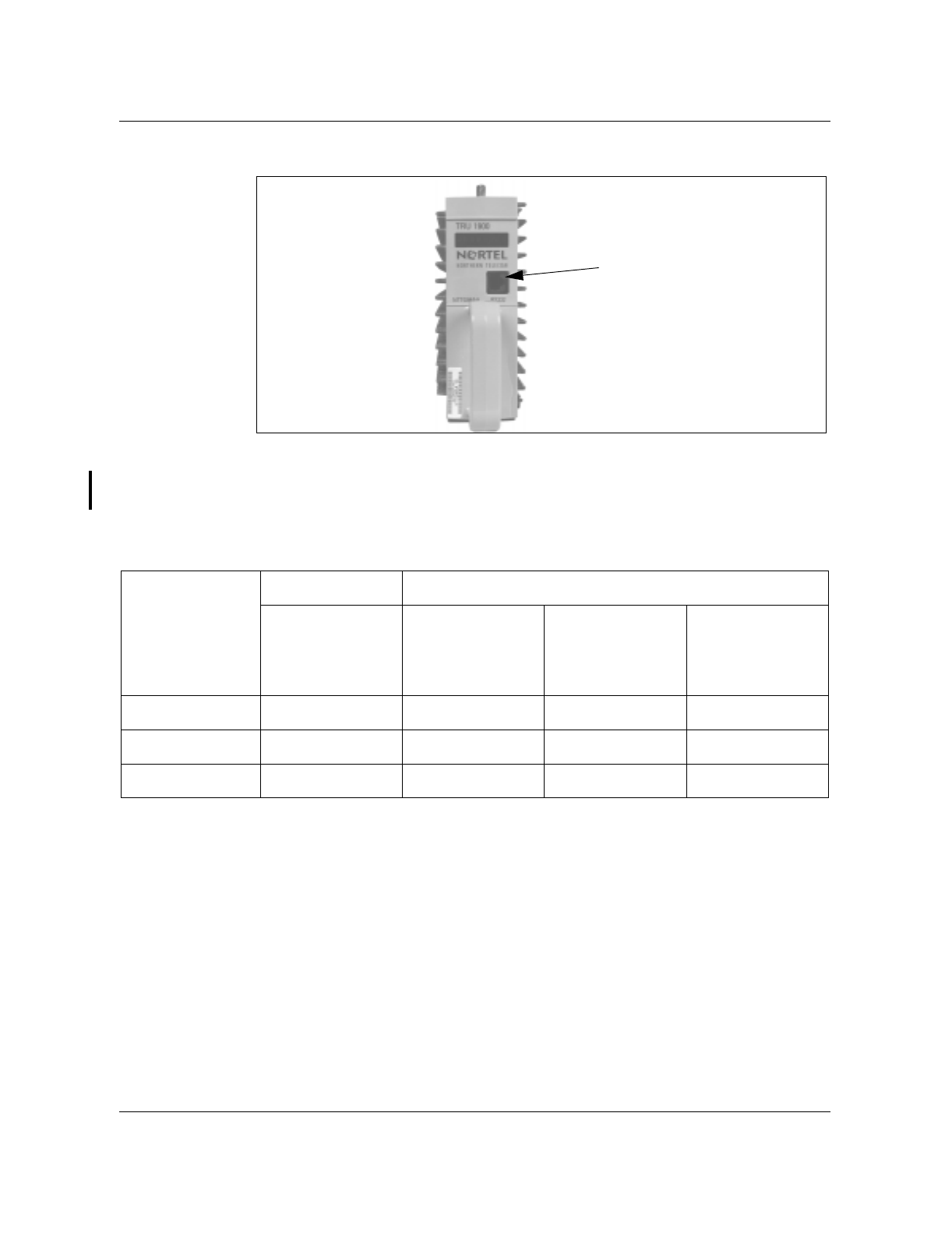
Figure 2-1
TRU front panel
Looking into the RJ-45 connector on the TRU front panel, pins are numbered
one to eight from top to bottom for the TRU 1900 and from bottom to top for
the TRU3 1900.
Table 2-1
Terminal interface connector pinouts
Setting up communications
Set up the Terminal Interface with the following communications parameters:
• 9600 baud
• eight bits, no parity
• one start bit, one stop bit
• 80 columns
• auto wraparound
•ANSI
• VT100 emulation
Function
TRU Terminal interface
TRU Front panel
RS-232 port pin
number RJ45
connector
25 pin
D-connector
pin number
9 pin
D-connector
pin number
8 pin Macintosh
connector pin
number
Tx from TRU 2323
Rx to TRU 3235
Ground 7754
RS-232
RJ45
connector
(Front plate for TRU3 1900
to be added)

Test equipment 2-5
Wireless Solutions TDMA 1900 Macrocell Cell Site Maintenance Manual MTX08
Interfacing the terminal with the TRU
Interfacing the TRU while it is “in service”
Interfacing to the TRU with a Terminal Interface while the TRU is in-service
(active by MTX), can be established by pressing the RETURN key on the
laptop once the physical connection is made. A “>” prompt will be printed on
the screen indicating that the terminal is “communicating” with the TRU.
Information required can be obtained by using the QUERY commands which
can be displayed by typing “HELP MSR”.
On-line help
Using the Fullscreen Monitor is simplified by an on-line help system. To access
it, type “HELP” or “?” in response to any prompt. A brief description of the
TRU terminal interface is displayed. Several on-line help categories are
available. Each category contains a one-line description of each command in
that category. The following categories of help commands are available:
• HELP HELP - Lists help categories
• HELP MTCE - Lists maintenance commands
• HELP TESTS - Lists test commands
• HELP MSR - List measurement and query commands
• HELP MONITOR - List commands within the monitor subsystem
Interfacing the TRU while it is Off-line or Manbusy
With the a terminal connected you can access the command line mode by
pressing the “Break” key on the terminal keyboard. The terminal will display:
For the TRU 1900:
TRU Terminal Interface
(C) Copyright 1990,1996 Bell Northern Research, Inc.
>
For the TRUIII 1900:
TRU-III Terminal Interface
(C) Copyright 1996-97 Nortel
>
At this point, there is about ten seconds before the TRU times-out and returns
to ROM IDLE. Before the ten seconds has elapsed, the Lap Timer must be
disabled, by typing:
>SET LT OFF
The Terminal Interface is now in the Command Line mode and ready to
receive commands. Please refer to Table 2-8, Table 2-9 and Table 2-10 for
Command Line Mode commands.

2-6 Test equipment
411-6201-500 Preliminary 03.03 July 1999
Disconnecting the Terminal Interface
Once the terminal session is completed, terminate the communication with
the following commands:
Fullscreen Mode: Use the Y command which initiates a restart and will
disconnect the communications.
Command Line Mode: Use EXECUTE RESTARTFLASH command to
disconnect the communications.
Note: Avoid removing the TRU from its transceiver shelf slot for the
purpose of executing a restartflash. If the TRU is detached from its
transceiver shelf backplane connection and then re-connected, it may
require some commissioning to ensure that all RF connections are
established correctly. Re-insertion of the TRUs to the backplane cause
wear and tear on the gold-plated backplane pins and may reduce
connectivity and increase path loss.
Remote Radio InterFace (RRIF)
The RRIF is a software feature introduced with MTX04. It allows remote
OAM access to cell site DRU’s from a MAP based terminal. Refer to NTP
411-2131-115 Remote Radio InterFace Reference.
Entering the Fullscreen mode
The primary purpose of the Fullscreen Monitor is to provide a means for
quickly commissioning a TRU in a cell site. It provides a more user-friendly
access to the TRU’s OAM test and maintenance functions than the command
line mode.
Note: The Fullscreen Monitor is intended for use on a TRU which is not
in an active call processing state.
The TRU must be at ROM idle (indicated on the front panel display) to
operate in the Fullscreen Monitor mode. The Fullscreen Monitor is capable of
two modes of operation, analog (AMPS) and digital (TDMA) and has the
ability to switch between either one.
Note: Although the AMPS (Advanced Mobile Phone System)
personalities (ACC (Analog Control Channel), AVC (Analog Voice
Channel), and ALR (Analog Locate Receiver)) are not valid operating
modes, the terminal interface software does not block any attempts to set
the TRU 1900 to these personalities. However, the AMPS personalities or
any related terminal interface commands are not guaranteed for valid
operation.
To enter the Fullscreen mode, at the command line prompt (>) type in the
following command:
Test equipment 2-7
Wireless Solutions TDMA 1900 Macrocell Cell Site Maintenance Manual MTX08
>SET FS ON
The SET FS ON command clears the existing display and changes the
display to the Fullscreen Display in the AMPS mode. To get to TDMA mode
select ‘A’, then return.
In the Fullscreen mode, the OAM commands are displayed and selected by
their alphabetic code. The results of each OAM command are displayed at
specific screen locations. Figure 2-2 shows the Fullscreen display for TRUs in
the TDMA mode.
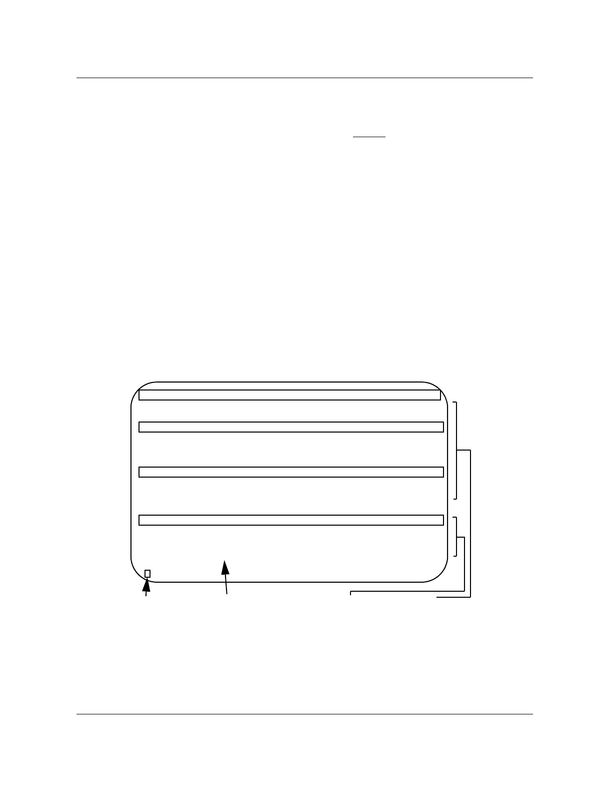
The Fullscreen display is divided horizontally into a status area and a
command area. The bottom line of the display is used as the “command
prompt” area; you may enter the appropriate command letter here. Directly
above the command area is the output message line where status and output
messages, such as selection parameters and error messages, are displayed.
Table 2-2 (pg 2-8) is a summary of the fullscreen commands and these
commands are explained in Table 2-3 to Table 2-7.
Figure 2-2
TRU Fullscreen display
DRU statusCommand menuOutput messageCommand prompt
TDMA Mode
---------TRU TERMINAL INTERFACE (C)1990,1991 Northern Telecom, Inc.-----------
Load: TRU2AH79 ROM: RDRUAB03 EEPROM: Passed HW Ver: p04 S/N: 530G3G9L
PA FW: -------- PA HW: ---- PA PEC: -------- PA S/N: ---------------
TDMA STATUS
Channel: ---- PA: off DVCC: 01 Antenna Port A: 1 B: 4
Synth Lock: NO TxPwrIndex: -- Slot: 1 Antenna Path: DIV
PA Alarm: off TxPwrStep: 4.00 Loopback: BCH
MaxTxPwr: 45.50 Tone Gen: off
------------------------------Signal Readings-----------------------------------
RX RSSI: Antenna Port: 1 2 3 4 5 6
RX DVCC RSSI Offset : 0.0 0.0 0.0 0.0 0.0 0.0
( ) : RSSI : - - - - - -
----------------------------------COMMANDS--------------------------------------
A) AMPS Mode F) Set MAXTXPOW M) Set Antenna Port S) Test TRU display
B) Set Channel G) Set DVCC N) Set Path T) Standalone TX
C) PA on/off H) Set Slot O) Set RSSI Offset U) Set TXPOWSTEP
D) PA LED on/off I) Tone Gen P) Detect DVCC,RSSI X) Exit
E) Set TXPOWIDX J) Loopback Q) Detect ALL RSSI Y) Restart TRU
-------------------------------------------------------------------------------

2-8 Test equipment
411-6201-500 Preliminary 03.03 July 1999
Fullscreen commands
Some commands are only applicable to the TRU in either the analog or digital
mode; others are applicable only when the TRU is in a particular state. Using
such a command when the TRU is not configured correctly results in the error
message below:
That function is not available in the TRU's current state.
A command is entered on the command line at the > prompt. You must press
the “Return” key to execute the command. For some commands, additional
parameters need to be entered and a prompt will appear on the message line.
Enter the appropriate parameter and press the “Return” key to execute the
command. Only one command may be executed at a time.
Note: The commands apply to both the TRU 1900 and the TRU3 1900
unless stated otherwise.

Test equipment 2-9
Wireless Solutions TDMA 1900 Macrocell Cell Site Maintenance Manual MTX08
Table 2-2
Fullscreen command summary
Note: Although the AMPS personalities (ACC, AVC and ALR) are not
valid operating modes, the terminal interface software does not block any
attempts to set the TRU 1900 to these personalities. However, the AMPS
personalities or any related terminal interface commands are not
guaranteed for valid operation.
A complete description of the fullscreen commands is given in Table 2-3 to
Table 2-7.
Code Amps Mode TDMA Mode
ASet TDMA Mode Set AMPS Mode
BSet Channel Set Channel
CSet PA on/off Set PA on/off
DSet PA LED on/off Set PA LED on/off
ESet TXPOWIDX Set TXPOWIDX
FSet MAXTXPOW Set MAXTXPOW
GSAT Transmit Set DVCC
HChange SAT Set SLOT
ISet Tone Gen Set Tone Gen
LSet Loopback Set Loopback
MSet Antenna Port Set Antenna Port
NSet Path Set Path
OSet RSSI Offset Set RSSI Offset
PDetect SAT/ST/RSSI Detect DVCC/RSSI
QDetect ALL RSSI Detect ALL RSSI
RSet Rx/Tx Audio —
SSet TRU Display Set TRU Display
TSet Audio Sens Stand-alone TX
USet TXPOWSTEP Set TXPOWSTEP
XExit Exit
YRestart TRU Restart TRU

2-10 Test equipment
411-6201-500 Preliminary 03.03 July 1999
These tables represent five groups according to the functions of the commands:
• Configuration functions for TRU operating parameters
• Transmit functions for TRU transmit status
• Receive functions for TRU receive status
• AMPS mode functions for functions available in AMPS mode only
Note: AMPs mode is not functionally supported.
• TDMA mode functions for functions available in TDMA mode only
Table 2-3
Fullscreen commands for configuration functions
Configuration functions (available to both the AMPS and the TDMA modes)
Code Command Status Action/initial value
ASet Mode AMPS,
TDMA Toggles between the AMPS mode display and the
TDMA mode display
BSet Channel 0000 Sets the current channel and updates the Channel
field on the display. If the TRU Synthesizer was
able to lock to the specified channel, the Synth
Lock field displays "YES"; otherwise, the Channel
field displays "----" and the Synth Lock field
displays "NO"
DSet PA LED On or Off Turns the alarm LED on the front panel of the PA
on or off; the status is shown in the SCLPA/PA
alarm field
ISet Tone Gen BCH,
RF, or
Off
Turns on either the tone generation (1004 Hz) on
the B-channel to the MTX, the RF tone generation
(1 kHz) on air, or turns off the tone generation.
The status is shown in the Tone Gen field
JSet Loopback BCH,
RF, or
Off
Sets either the B-channel audio loopback (to
MTX), the RF loopback (to mobile), or Off (no
Loopback). The status is shown in the Loopback
field
STest Display
(for TRU 1900) — Verifies the TRUs 8-character LED display by
alternately showing the following three patterns on
the LED display until the Return key is pressed:
00000000
* * * * * * * *
. . . . . . . .
XExit — Leaves fullscreen monitor mode, clearing the
screen and returning to command line mode

Test equipment 2-11
Wireless Solutions TDMA 1900 Macrocell Cell Site Maintenance Manual MTX08
Table 2-4
Fullscreen commands for transmit functions
Transmit functions (available to both the AMPS and the TDMA modes):
Code Command Status Action/initial value
YRestart TRU W or
CExecutes either a ROM level reset (C = COLD) or
a FLASH level restart (W = WARM); you are
prompted for the type of restart to be performed
Note: This restarts the TRU and forces an exit from the fullscreen mode.
CSet PA on/off On or Off Turns the PA on or off; the status is shown in the
SCLPA/PA field
ESet TXPOWIDX 0 to 7 Sets the current power level attenuation number.
The TRU has maximum output power when power
level is set at “0” (no attenuation); the status is
shown in the Power Level or TxPwrIndex field
Note: It is recommended that the power level be set to “0” unless otherwise specified as a
site requirement.
FSet PA Max
Power 30.5 dBm to 43.5
dBm Sets the upper bound on output power of the PA
(from 30.5 to 43.5 dBm) to the specified dBm
value with a resolution of.01dB
USet PA Power
Step size Set TXPOWSTEP
dB_adjustment Adjusts the output power PA step size of the PA
by the amount specified; the power step value can
be from 0.00 to 100.00 dB in steps of 0.01 dB
—end—

2-12 Test equipment
411-6201-500 Preliminary 03.03 July 1999
Table 2-5
Fullscreen commands for receive functions
Receive functions (available to both the AMPS and the TDMA modes):
Code Command Status Action / initial value
M Set Antenna Port (1 or 2 or 3)
(4 or 5 or 6) Selects antenna ports to use on path A and B. The
Antenna Port field will show:
Port A: 1, 2 or 3 Port B: 4, 5 or 6
Note: Only 1 and 4 can be selected in Omni cell sites.
NSet Path A
B
DIV
Selects the antenna path. The status is shown in
the Antenna Path field. DIV indicates diversity
switching between paths A and B.
OSet RSSI Offset 00.0 Sets the RSSI Offsets (MCGAIN) for the ports on
the specified antenna path. It should be performed
during installation only. Do not change the values
at this time.
QDetect All RSSI —
Signal reading area
displays:
-000.0
Constantly measures RSSI detected on all the six
antenna ports until the Return key is pressed.
Updates the six RSSI fields on the right hand side
of the Signal Readings area on the display
Note: The current path and port settings cannot be determined after this command is
executed; the corresponding status fields will be cleared.

Test equipment 2-13
Wireless Solutions TDMA 1900 Macrocell Cell Site Maintenance Manual MTX08
Table 2-6
Fullscreen commands for AMPS mode functions
AMPS mode functions (available to the AMPS mode only):
Code Command Status Action/Initial Value
GSet SAT Transmit On or Off Turns on/off generation of SAT; the status is
shown in the SAT TX field
HChange SAT 5970,
6000, or
6030
Sets the transmit SAT frequency; the selected SAT
frequency is shown in the SAT TX field
KSet Compander On or Off Sets TX compression and RX expansion on or off;
the status is shown in the compandor field
LTransmit
Wideband Data
(for TRU 1900)
— Enables wideband data transmission; the TRU will
begin to transmit wideband data at the currently
selected MPA power level and the wideband data
transmission is disabled by pressing the Return
key.
PDetect
SAT,ST,RSSI SAT, ST, RSSI or A
(all)
Signal reading area
displays:
-000.0
Constantly measures SAT, ST, and RSSI detected
on the assigned port of the current path (set by
the M and N commands) until the Return key is
pressed; updates the RX SAT, RX ST, and RSSI
fields on the left hand side of the signal readings
area on the display
Note: The M and N commands must be set prior to this command
RSet RX/TX Audio TX,
RX,
BOTH, or
OFF
TX—unmutes the TX audio; mutes the RX audio
RX—mutes the TX audio; unmutes the RX audio
BOTH (TX RX)—unmutes both TX and RX audio
OFF—mutes both TX and RX audio
The status is shown in the audio field
TSet TX/RX Audio
Sens TX -xx.x, or
RX -xx.x Sets the audio sensitivity for the entered TX or RX
path. The selected audio sensitivity levels are
shown in the Audio Sens fields.
The limits for the TX and RX audio sensitivity are:
TX Sens: -28.0 dBm ð -xx.x ð -10.0 dBm
RX Sens: -28.0 dBm ð -xx.x ð -16.0 dBm
Note: Set both TX and RX sens to -18.0 in the tests described in this document.

2-14 Test equipment
411-6201-500 Preliminary 03.03 July 1999
Table 2-7
Fullscreen commands for TDMA mode functions
Terminal interface command line mode
The Command Line Mode of the Terminal Interface can be used to execute
three types of commands:
• maintenance commands
• measurement commands
• test commands
Each type of command serves a specific function as outlined in the following
sections.
Maintenance commands
Each maintenance function may be used by an operator to aid in the diagnosis
and repair of faults in the TRU. There are periodic maintenance functions that
must be performed at regular intervals these schedules can be found in
Chapter 3, Maintenance Schedules in this manual.
Note: The Command Line mode and the Fullscreen mode are intended
for testing purposes only. Do not place the TRU into either one of these
modes during call processing. The call in progress may be dropped.
Table 2-8 gives the name, terminal command, state allowed, and description
for the command line mode maintenance commands.
TDMA mode functions (available to the TDMA mode only):
GSet DVCC 01 to FF
(hexadecimal) Sets the DVCC transmitted by the TRU when the
MPA is enabled; DVCC is an 8-bit verification code
transmitted between the mobile and the base
station; it is used in TDMA cellular to differentiate
between mobiles on the same frequency
HSet Slot 1 to 3 The TRU currently supports Full Rate (3 slots)
coding, that is, three mobiles sharing one
frequency; this command sets the current TDMA
slot used by the TRU for DVCC transmission and
signal measurements
PDetect DVCC,
RSSI -000.0
Y/N
Displays if current DVCC setting is detected and/or
the RSSI measurement on the current slot of the
antenna setup. The status will be displayed in the
RX RSSI and RX DVCC fields
TStand-alone TX On or Off Allows the TRU to transmit without using a PA. This
is used for either low power testing or on low power
cell sites

Test equipment 2-15
Wireless Solutions TDMA 1900 Macrocell Cell Site Maintenance Manual MTX08
Note: Only capitalized characters need to be entered.These commands
apply to the both the TRU 1900 and the TRU3 1900 unless stated
otherwise.
Table 2-8
Command line maintenance commands
Name Terminal
command State
allowed Description
DRU Reset Execute RESET Any Causes the DRU to completely reset all of its
systems and restart processing at the ROM level
DRU Restart Execute
RESTARTFLASH Any Causes the DRU to restart processing within the
flash load
Display Message
(for TRU 1900) Set DISPLAY
string Any Sets the front panel display on the TRU to the
specified string
Blinking Display
(for TRU 1900) Set BLINKING
on/off Any Causes the front panel display of the TRU to blink
on and off if it is set to ON
Set Personality Set PERS
ACC/ALR/AVC/
TLR/TTC
Any The DSPs are reset and set to the given
personality; the personality may be IS-54 CCH,
AMPS LCR, AMPS VCH, TDMA LCR, or TDMA
TCH
Set Channel Set CHANNEL
chan All but
maint. Sets the receive and transmit channel to the given
value
Rx Audio On/Off Rx Audio On/Off VCH Turns on (unmute) or off (mute) the transceiver
audio output upstream (to the ICRM)
Tx Audio On/Off Set TXAUDIO
on/off VCH Turns on (unmute) or off (mute) the transceiver
audio output downstream (to the mobile)
Set Audio
Sensitivity Set AUDSENS
TX/RX
dBm_value
VCH Sets the audio sensitivity for the transmit or
receive paths
SAT Generation
On/Off Set SATGEN
on/off VCH Turns on/off generation of supervisory audio tone
SAT Frequency
Select Set TXSATCC cc VCH Selects frequency to be used for SAT generation
Receive SAT
Color Code Set RXSATCC
detector cc VCH Configures the SAT detector to look for specified
color code
Receive Path
Selection Set PATH
A/B/CURRENT
/D/V
VCH Sets the diversity receiver to be either the A(0) or
B(1) path, or enables diversity switching (2)
-sheet 1 of 4-

2-16 Test equipment
411-6201-500 Preliminary 03.03 July 1999
Path Antenna
Select Set DIVPORT
path_A_port:1/2
path_B_port:3/4
VCH Establishes a nailed connection for the given
antenna
Antenna Switch
Mode Set ASWMODE
A/B Fixed VCH Sets the antenna switch mode for the given path;
the path can be A(0) or B(1); the mode is fixed
Compandor
Control Set
COMPRESSION/
EXPANSION
on/off
VCH Controls the dynamic range compression and
expansion of the TRU compandor
Set C-Side Tone
Generation Set BCHTONE
on/off VCH Enables or disables tone generation to the ICRM
Set C-Side
Loopback Set BCHLOOP
on/off All but
maint. Enables or disables TCM loopback to the ICRM
Set Mobile
Loopback Set RFLOOP
on/off VCH, or
CCH Enables or disables the RF loopback capability of
the TRU
Transmitter Tone
Generation
Control
Set RFGEN
on/off VCH Turns on or off generation of transmitter test tone
PA On/Off Set PA on/off VCH,
CCH, or
TTC
Turns the PA on or off
Set
Transmission Set TRANSMIT
on/off VCH,
CCH, or
TTC
Enables or disables the transmitter in the TRU;
this command functions the same as the Set PA/
PA on/off command
Set PA Max
Power Set MAXTXPOW
dBm_level VCH,
CCH, or
TTC
Sets the output power of the PA (from 30.5 dBm to
43.5 dBm) to the specified dBm value +/- .01 dB
Set PA Power
Index TXPOWIDX
index VCH,
CCH, or
TTC
Sets the PA power to the specified DPC index; the
index is an integer (from 0 to 7) that corresponds
to a dBm power level
Set PA Power
Step Set
TXPOWSTEP
dB_adjustment
VCH,
CCH, or
TTC
Adjusts the output power DPC step size of the PA
by the amount specified
Table 2-8
Command line maintenance commands (continued)
Name Terminal
command State
allowed Description
-sheet 2 of 4-

Test equipment 2-17
Wireless Solutions TDMA 1900 Macrocell Cell Site Maintenance Manual MTX08
PA Type Set PATYPE type VCH,
CCH, or
TTC
Allows for the setting of the type of PA being used;
MPA indicates that a MPA is being used; SCLPA
indicates that a SCLPA is being used; NONE
indicates that no PA is used–the TRU is using its
own internal PA to output a modulated signal
(
Note:
1900 Macrocell does not support the none
mode.)
Nominal
Application Gain Set NOMGAIN
dB_level VCH,
CCH, or
TTC
Provides a method of compensating for nominal
losses or gains as a result of cell site hardware
used with the TRU (range: ± 100dB; 0.01 dB
resolution)
Installation
Calibration Set INSTCAL
dB_level VCH,
CCH, or
TTC
Provides the capability to correct the power
reading of the TRU (range: ± 100dB; 0.01 dB
resolution)
PA LED On/Off Set PALED on|off Any Turns the fault indicator LED on PA modules on or
off
LAPD Timeout
Control Set LT/
LAPDTIMEOUT
on/off
Any Enables/disables the LAPD timeout; if the TRU
detects loss of the LAPD link, it resets itself after
10-12 seconds; with the LAPD timeout set off, the
TRU does not reset, which is necessary for stand
alone testing
Message Trace
Control Set TRACE
from/to ICP/MPA/
DSP on/off
Any Enables or disables message trace at the
specified interface point in the specified direction
Message
Injection Run INJECT
from/to ICP/MPA/
DSP bytes
Any Injects the specified message trace (bytes) at the
specified interface point in the specified direction
Set Multicoupler
Gain Set MCGAIN A/B
dB_loss1
dB_loss2
dB_loss3
Any Sets the compensation for the gain through the
antenna and multicoupler system for the antennas
connected to the specified path
Enable
fullscreen Mode Set FS on VCH,
CCH,
ALR, or
Maint.
Enables the fullscreen mode of the terminal
interface
Digital
Verification
Color Code
Set DVCC
dvcc_value
slot_number
TTC Sets the DVCC value for the slot specified or all
slots if ALL is entered as the slot number
Table 2-8
Command line maintenance commands (continued)
Name Terminal
command State
allowed Description
-sheet 3 of 4-

2-18 Test equipment
411-6201-500 Preliminary 03.03 July 1999
Measurement commands
Measurements of operational parameters are taken periodically and on
demand from the ICP or the terminal interface. If a measurement exceeds a
threshold value, the ICP receives an alarm message. Table 2-9 gives the name,
terminal command, state allowed, and description of the measurement
commands.
Clear SWERR
Table Set
RSETSWERR Any Clears the SWERR table and resets the current
SWERR count to zero
Fault Simulation Run FAULTSIM
fault Any Simulates the specified fault by displaying the fault
on the front panel and sending the fault up to the
ICP
SWERR
Simulation Run SWERRSIM
class code Any Logs an artificial software error that is displayed
on the front panel
OM Simulation Run OMSIM
omtype Any Pegs the occurrence of the specified OM
Table 2-9
Command line measurement commands
Name Terminal
command State
allowed Description
Reset Reason Query RESET
REASON Any When the DRU is reset, a reason code is stored in
non-volatile memory and can be read when the
DRU is active again to give the reason for the last
reset; if no reason is stored, then the reset was
caused by some unsolicited event
SAT Status Query SAT
detector VCH Indicates that SAT status on the receive path for
the current SAT color code
In TRU3, the status indicates the actual SAT
value.
ST Status Query ST VCH Indicates the ST status on the receive path
Uptime Counter Query UPTIME Any The time that the DRU has been operating since
the last reset in days, hours, and minutes
Previous Uptime
Counter Query
PREVUPTIME Any The time that the DRU had operated before the
last reset in days, hours, and minutes
-sheet 1 of 2-
Table 2-8
Command line maintenance commands (continued)
Name Terminal
command State
allowed Description
-sheet 4 of 4-

Test equipment 2-19
Wireless Solutions TDMA 1900 Macrocell Cell Site Maintenance Manual MTX08
RSSI
Measurement Query RSSI Any In the TTC state, indicates RSSI readings for each
slot; in other states, indicates current RSSI
reading at the diversity switch
Multicoupler
Gain Settings Query MCGAIN Any The multicoupler gain compensation in dBm for
each antenna on both receive paths
Audio Sensitivity
Settings Query AUDSENS VCH The audio sensitivity settings in dBm for the
transmit and receive paths
Hardware
Version Number Query HWVERS Any The hardware release number of the TRU being
queried
Continuous
Status Display Query STATUS
on/off
DIV/ALL/CUR
R/ST/SAT/A
VCH Enables/disables a continuous display of channel
number, RSSI, SAT, and ST of the diversity port or
the channel number and RSSI readings from each
port
PA status Query
PASTATUS Any The PA information (PA type, current power, power
reference, step size, DPC index, and alarm status)
being queried
MPA Firmware
Version Number
(for TRU 1900)
Query MPAFW Any The MPA/PA firmware version number of the DRU
being queried
Note:
When using an TRU 1900, this command
applies to the MPA mode only
Digital
Verification
Color Code
Query DVCC TTC The DVCC status for each slot
Display SWERR
Table Query SWERR Any The SWERR class, SWERR code, and
associated information words
PA Maximum
Power Setting Query
MAXTXPOW VCH,
CCH, or
TTC
The adjusted maximum SCLPA power setting in
dBm, stored in the TRU and the delta adjust from
the SCLPA.
PA Power Step
Size Query
TXPOWSTEP VCH,
CCH, or
TTC
The adjusted SCLPA power step size setting in
dB, stored in the TRU and the delta adjust from
the SCLPA.
Radio Load
status Query LOAD Any For obtaining load name of the TRU.
Radio status
(for TRU3 1900) Query RADIO Any For obtaining information on the status of the
TRU3 1900. This information is provided through
an alphanumeric display on the TRU 1900.
Table 2-9
Command line measurement commands (continued)
Name Terminal
command State
allowed Description
-sheet 2 of 2-

2-20 Test equipment
411-6201-500 Preliminary 03.03 July 1999
Test commands
Testing ensures the proper working order of the TRUs components. Table 2-
10 gives the name, terminal command, state allowed, and the action
associated with each test command.
Table 2-10
Command line test commands
Name Terminal
Command State
Allowed Action/Initial Value
RAM Read/Write
Test
(for TRU 1900)
TEST RAM Any The read/write memory is checked to ensure that
all locations can be written to and read, and that
each address accesses a unique memory
location.
Flash Load CRC
Test TEST FLASH Any This test reads all data stored in flash EEPROM,
calculates the CRC, and compares this value
against the CRC stored in the flash EEPROM
DSP Sanity Test TEST DSP ALL Maint. This test checks the basic sanity of the DSPs by
checking for basic messaging ability in each one.
Individual DSP
Sanity Test TEST DSP
dspid# Maint. This test is similar to the previous one except that
the sanity test is only run on a particular DSP chip.
Calibration Table
Sanity Tests
(for TRU 1900)
TEST EEPROM Any Calibration information is stored in EEPROM
along with an associated CRC. This test
calculates each table’s CRC and compares to the
stored CRC. If a table has not been written, the
result is n/a.

3-1
Wireless Solutions TDMA 1900 Macrocell Cell Site Maintenance Manual MTX08
3Maintenance schedules
This section provides the maintenance reference chart and the corresponding
periodic check lists, and when necessary, refers to detailed process procedures
in this manual.
Periodic maintenance records
Periodic maintenance allows for
• the detection and replacement of degraded equipment before it affects
service
• preventative steps to protect equipment from damage or degradation
To support these functions, records must be kept. Records allow you to
• recognize deteriorating performance by comparing current and past test
results
• ensure that all steps required to protect equipment have been taken
• create a maintenance history of a cell site; thereby allowing you to plan
for the future and predict future maintenance needs
• provide information to decide sparing levels and "out of expectation"
failure level for specific equipment
Manuals and records
For maximum benefit, manuals, site logs, and maintenance records should be
organized, kept on site and readily accessible so that call-out staff have access
to and can determine the maintenance history of a particular site. All records
should be completed before leaving the site.
Schedule for periodic cell site maintenance
Regularly scheduled visits are important for the preventative maintenance of a
cell site. However, if maintenance teams are responsible for a number of cell
sites, maintenance schedules for the different sites should be staggered so that
labour time is more effectively and efficiently managed. Table 3-1 is an
example of a maintenance schedule for six cell sites where the periodic
routines are distributed evenly throughout a one year period.

3-2 Maintenance schedules
411-6201-500 Preliminary 03.03 July 1999
A cell site maintenance reference chart and preventive maintenance check
lists are provided.
Table 3-1
Maintenance schedule example
Cell Jan Feb Mar Apr May Jun Jul Aug Sept Oct Nov Dec
#1 1 yr mo mo qtr mo mo 6 mo mo mo qtr mo mo
#2 mo mo 1 yr mo mo qtr mo mo 6 mo mo mo qtr
#3 mo qtr mo mo 1 yr mo mo qtr mo mo 6 mo mo
#4 6 mo mo mo qtr mo mo 1 yr mo mo qtr mo mo
#5 mo mo 6 mo mo mo qtr mo mo 1 yr mo mo qtr
#6 mo qtr mo mo 6 mo mo mo qtr mo mo 1 yr mo

Maintenance schedules 3-3
Wireless Solutions TDMA 1900 Macrocell Cell Site Maintenance Manual MTX08
TDMA 1900 Macrocell cell site maintenance reference chart
Table 3-2
Cell site maintenance reference chart
Every
Visit Monthly Quarterly Semi-
Annual Annual
CE and RF frames
Breakers, fans, and fuses X
LED checklist X
Frame and equipment voltage check X
DC inspection X
VSMO tests X
ACU tests X
Tx Insertion loss test X
Frame equipment fan cleaning X
Transmission facilities:
Copper Audio Link (T1) X
Power:
Breakers X
Battery X
Rectifiers: X
Voltage level X
Alarm cut off X
Main generator X
Backup generator X
Building AC service X
-sheet 1 of 2-

3-4 Maintenance schedules
411-6201-500 Preliminary 03.03 July 1999
Antennas and towers:
General structure X
Antennas X
Pressurized transmission lines X
Housekeeping
Heating/air conditioning X
Administration X
Dust control X
Site performance X
Outside grounding X
Inside grounding X
Outside area X
Cell site building X
Every
Visit Monthly Quarterly Semi-
Annual Annual
-sheet 2 of 2-

Maintenance schedules 3-5
Wireless Solutions TDMA 1900 Macrocell Cell Site Maintenance Manual MTX08
TDMA 1900 Macrocell cell site EVERY VISIT checklist
Date:____________________________ Performed by:___________________________
Table 3-3
Cell site EVERY VISIT checklist
Reference
pages ;
CE and RF frames
Check all RIP breakers on all CE and RF frames. 4-2
Verify all cooling fans are working on each CE and RF frame 4-3
Check fuses 4-3
LED checklist 4-3
Cell site building
HVAC:
Check air filters on air exchange/conditioner equipment
Check that the thermostat setting is between 19°-22° C (67°-74° F)
Verify HVAC operation by varying the thermostat
9-7
Check all interior lights -
Verify automated security system by tripping alarm if applicable (reset after
test) -
Verify the presence of a fire extinguisher & check expiry date -
Check for leaks in the roof -
Check the condition around windows/doors for weather proofing -
Check for deterioration of paint on walls, repaint as necessary -
Check cable access ways through the walls for deterioration -
Perform general housekeeping duties 9-8
Complete manuals, site logs, and records -
Outside site area
Security site checks 9-7
Tower lighting check 9-6
Inspect antenna grounding 9-6
Site grounds keeping 9-8
Check that there are no overhead lines down -
Antennas and tower
Pressurized transmission lines 9-6
Power
Main generator 9-3
Check breakers in the building panel box (check for tripped breakers) -

3-6 Maintenance schedules
411-6201-500 Preliminary 03.03 July 1999
TDMA 1900 Macrocell cell site MONTHLY checklist
Date:____________________________ Performed by:___________________________
Table 3-4
Cell site MONTHLY checklist
Reference
Pages ;
Perform the EVERY VISIT routine checks 3-5
Power:
Battery (liquid- electrolyte):
Cell voltages
Electrolyte levels
Battery terminals
Exhaust system and sensor
9-2
Rectifier:
Check output voltage as per manufacturer’s specifications 9-2
Housekeeping:
Dust control 9-7
Maintenance schedules 3-7
Wireless Solutions TDMA 1900 Macrocell Cell Site Maintenance Manual MTX08
TDMA 1900 Macrocell cell site QUARTERLY checklist
Date:____________________________ Performed by:___________________________
Table 3-5
Cell site QUARTERLY checklist
TDMA 1900 Macrocell cell site SEMI-ANNUAL checklist
Date:____________________________ Performed by:___________________________
Table 3-6
Cell site SEMI-ANNUAL checklist
Reference
Pages ;
Perform the EVERY VISIT routine checks 3-5
Perform the MONTHLY routine checks 3-6
CE and RF frames
Frame and equipment voltage checks 4-5
DC inspection 4-4
Equipment fan cleaning 9-7
Power
Backup generators:
Operation
Fluid levels
9-3
Transmission facilities:
Copper Audio Link (T-1) 9-2
Reference
pages ;
Perform the EVERY VISIT routine checks 3-5
Perform the MONTHLY routine checks 3-6
Perform QUARTERLY routine checks 3-7
3-8 Maintenance schedules
411-6201-500 Preliminary 03.03 July 1999
TDMA 1900 Macrocell cell site ANNUAL checklist
Date:____________________________ Performed by:___________________________
Table 3-7
Cell site ANNUAL checklist
Reference
Pages ;
Perform the EVERY VISIT routine checks 3-5
Perform the MONTHLY routine checks 3-6
Perform QUARTERLY routine checks 3-7
Perform SEMI-ANNUAL routine checks 3-8
CE and RF frames:
Tx Insertion loss test 7-1
ACU tests:
Alarm input points 8-2
Output contact points 8-2
VSMO tests:
Oscillator frequency test 5-1
Oscillator level 5-1
Power:
Rectifiers: Test the alarm/cut out sections on the rectifiers by adjusting the
high and low voltage 9-2
Building AC service: Check the building AC main service 9-3
Inside grounding:
Verify frame grounds 9-3
Verify that all inside ground connections lead back to the common ground
point 9-3
Check all connections, ensure new/changed equipment is properly grounded 9-3
Check that the transmission line to the antennas is lightning protected where
it comes into the building 9-4
-sheet 1 of 3-

Maintenance schedules 3-9
Wireless Solutions TDMA 1900 Macrocell Cell Site Maintenance Manual MTX08
Outside Grounding:
Using binoculars or a spotting scope, verify that the air lightning rod and
antennas are still attached to the tower and grounding system 9-4
Verify that the antenna feed cables are grounded at both ends 9-4
Verify that the cables and clamps attaching the tower and waveguide bridge
to the grounding system are secure 9-4
Verify that the cables and clamps connecting the guy wires to the grounding
system are secure 9-4
Verify that transmission cables are grounded at both the top and bottom of
the tower, and the building entrance 9-4
Buildings with metal walls, roof or base, all metal parts are grounded 9-5
Site fence, fuel tank or other metal structures are grounded 9-5
Check that grounding cables and clamps are secure 9-4
Antennas and towers:
General structure:
Check the tower base for cracks, concrete break up and upheaval 9-5
Check all guy anchors for cracks or upheaval 9-5
Check guy tension and attachment 9-5
Check fasteners for security 9-5
Check all components for rust 9-5
Check for flaking paint (often a sign of over-stress) re-paint if necessary 9-5
Check that the transmission line is adequately supported and protected
between the cell site building and the antenna tower 9-6
When tower is climbed, check grounding on the higher parts 9-5
When tower is climbed, check the tower lights 9-5
Antennas: When tower is climbed, perform structural inspection of antenna:
• Check for correct orientation and tilt
• Check for cracks, dents, burns
• Check for fasteners, attachment and security
• Check for transmission line and ground attachment security
• Check for audible gas leakage in pressurized system
9-6
-sheet 2 of 3-

3-10 Maintenance schedules
411-6201-500 Preliminary 03.03 July 1999
Site performance:
Confirm fringe coverage 9-6
Confirm call handoffs 9-6
Antenna sweep test 6-5
Housekeeping:
Heating/ air conditioning:
• Perform heating manufacturer's annual maintenance recommendation
• Ensure unit is properly secured in location
• Verify that the compressor and the fan motors are fully operational
• Verify that the drainage system is fully operational
• Check for insects, mouse and birds nest in intake and exhaust systems
9-7
Administration:
Site licenses 9-8
Statutory requirements 9-8
-sheet 3 of 3-
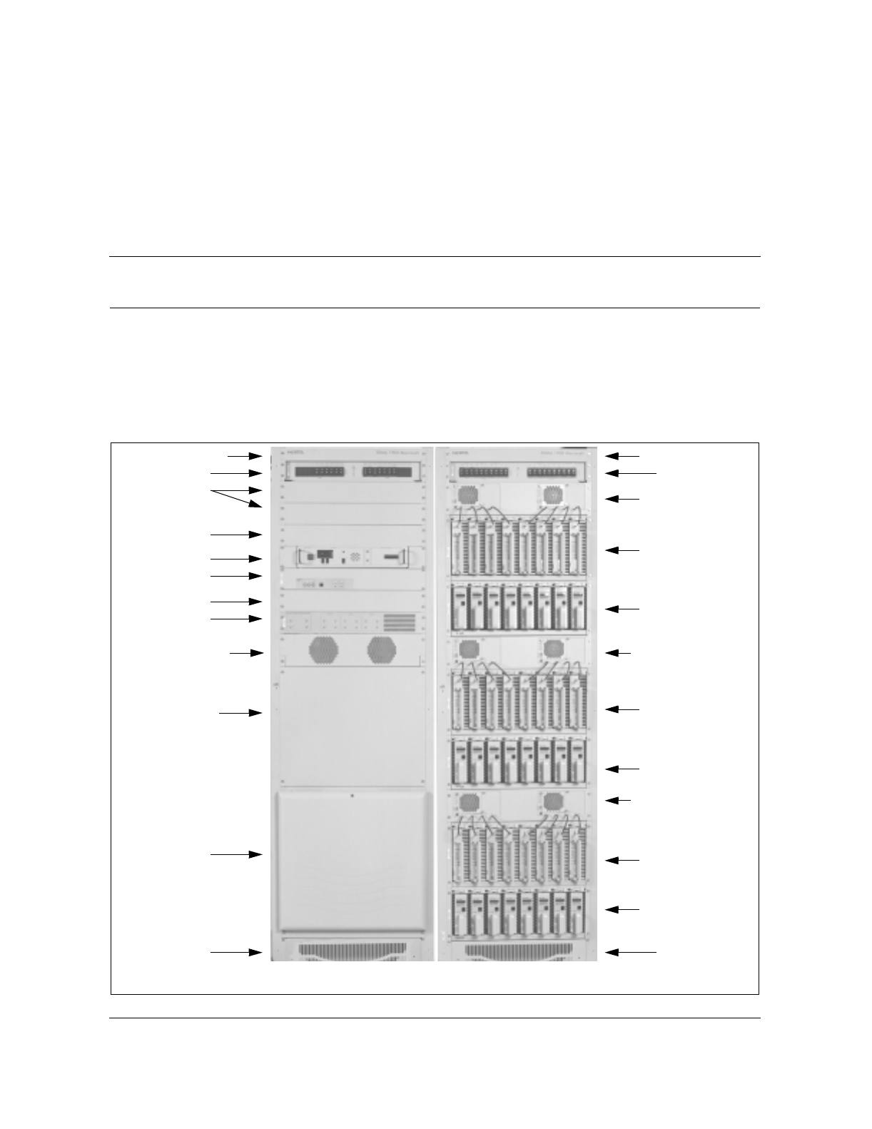
4-1
Wireless Solutions TDMA 1900 Macrocell Cell Site Maintenance Manual MTX08
4CE and RF frames
CE and RF frames
Figure 4-1 shows the location of equipment in the Common Equipment (CE)
and Radio Frequency (RF) frames of a typical cell site.
Figure 4-1
Typical cell site frame layout
Brandliner
RIP
Blank
Tri-duplexer
shelf
ACU
VSMO
Blank
RPDU
LRM shelf
Site Manager
ICRM
Brandliner
RIP
ATC / duplexer
shelf
SCLPA shelf
TRU shelf
BaseBase
ATC / duplexer
shelf
SCLPA shelf
TRU shelf
ATC / duplexer
shelf
SCLPA shelf
TRU shelf
CE frame RF frame
NTTG50AA NTTG10AA
(Future)
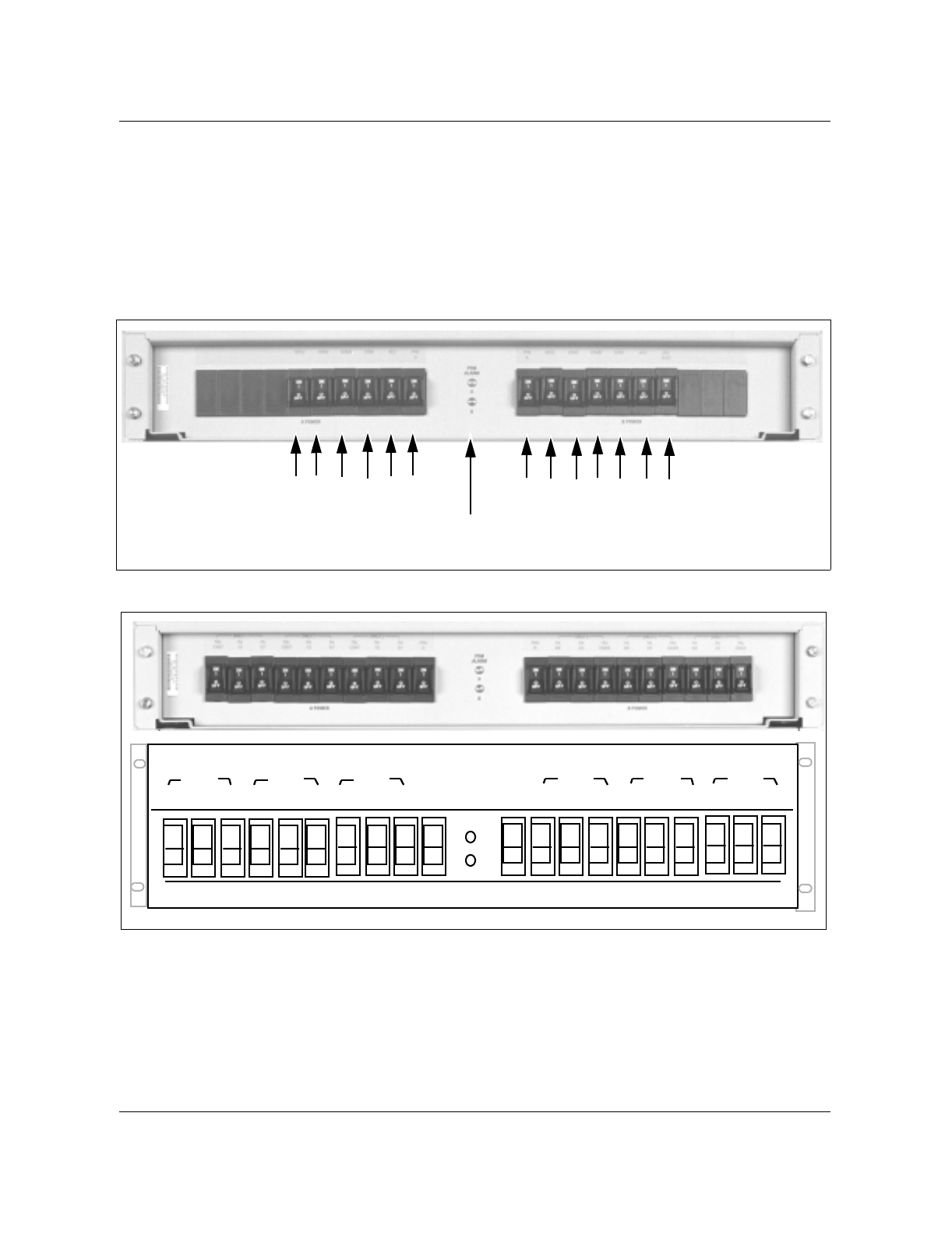
4-2 CE and RF frames
411-6201-500 Preliminary 03.03 July 1999
Breakers
The ACU monitors the status of the breakers. It is good practice however to
check that the correct breakers are on. Refer to Figure 4-2 for the CE and
Figure 4-3 for the RF frame dc breaker panel layout. If a breaker is not
functioning properly refer to TDMA 1900 Macrocell Troubleshooting Guide,
411-6201-501.
Figure 4-2
CE frame RIP panel layout
Figure 4-3
RF frame RIP panel layout
RVNIAPPRVNI A
123456 7891011 12 13
S
M
O
S
M
P
D
U
C
R
M
C
UF
M
A
F
M
B
P
D
U
S
M
O
S
MC
R
M
C
U
B
I
A
S
PFM
LEDs
dc breakers
B power
A power
PFM
ALARMS
A
B
PA
1/3
TRU
1/3/5/7 5/7
Pwr
Filter
A
Pwr
Filter
BTRU
2/4/6/8
PA
2/4
PA
SHELF 3SHELF 2SHELF 1 SHELF 2SHELF 3 SHELF 1
ON
OFF
ON
OFF
ON
OFF
ON
OFF
ON
OFF
ON
OFF
ON
OFF
ON
OFF
ON
OFF
ON
OFF
ON
OFF
ON
OFF
ON
OFF
ON
OFF
ON
OFF
ON
OFF
ON
OFF
ON
OFF
ON
OFF
ON
OFF
PA
6/8
TRU
2/4/6/8
PA
2/4
PA
6/8
TRU
2/4/6/8
PA
2/4
PA
6/8
PA
1/3
TRU
1/3/5/7 5/7
PA PA
1/3
TRU
1/3/5/7 5/7
PA

CE and RF frames 4-3
Wireless Solutions TDMA 1900 Macrocell Cell Site Maintenance Manual MTX08
Fans and fuses
Part of the function of the ACU is to monitor the status of the fans, and fuses.
It is good practice however to check that the shelf fans are working. If the
ACU indicates a fan or module failure, and there is no apparent power to the
unit, check the fuse. If necessary replace the fuse with one of the same type
and rating. If the unit is still not functioning properly refer to TDMA 1900
Macrocell Troubleshooting Guide, 411-6201-501.
LED checklist
Verify the proper operation of various cell site equipment using the LED
status checklist shown in Table 4-1. If any other LED condition is present
other than the desired state refer to TDMA 1900 Macrocell Troubleshooting
Guide, 411-6201-501.
Table 4-1
LED status checklist
Equipment LED description Desired state
CE RIP PFM alarms A and B on (green)
ACU Four digit alarm display no alarms flashing
VSMO Unit pass
Alarm
on (green)
off
RPDU LRM and RRM alarm indicator on the front
panel.
A fan module alarm LED for the RPDU and
the LRM shelf on the front panel.
A green status LED on the
RPDU indicates power with no
alarms within the RPDU.
RF RIP PFM alarms A and B on (green)
ATC Power
Alarm
Fan alarm
on (green)
off
off
TRU 1900 8 character display no fault msg
TRU3 1900 Normal
Alarm (LOS/FAIL LED)
on (green)
off (red)
SCLPA Normal
Alarm
on (green)
off

4-4 CE and RF frames
411-6201-500 Preliminary 03.03 July 1999
Dc power inspection
An orderly installation of dc power is required at the cell site to ensure ease of
expansion as traffic increases. Refer to Table 4-2 and Table 4-3 for inspection
procedures.
Table 4-2
Dc power inspection
Step Action Observation
1Verify that the dc power cables from the
breaker panel on the power bay to the
equipment racks have been run in an orderly
fashion and are secured to the runway.
2Verify that the lugs have been installed
correctly and, if terminated on aluminum
busbars, have been treated with anti-oxidant.
3Verify that the minimum bending radius has
not been exceeded on the power cables see
Table 4-3.
4Verify that the breaker positions on the
power bay have been labeled and are cabled
as indicated on the labels.
Note:
See Figure 4-2 for dc breaker panel
layout.
5Verify that the RF bays are bonded to the
principle ground bar line-up feeder with a #6
AWG jumper.
Table 4-3
Minimum bending radii of power cables
Wire Size Inches Millimeters Wire Size Inches Millimeters
14 AWG 11/16 17.5 3/0 AWG 3 3/16 80.5
12 AWG 3/4 19.6 4/0 AWG 3 7/16 87.6
10 AWG 15/16 23.1 300 MCM 4 1/8 104.6
8 AWG 1 3/16 31.0 350 MCM 4 3/8 111.5
6 AWG 1 1/2 39.6 400 MCM 4 5/8 117.3
4 AWG 1 3/4 45.7 500 MCM 5 1/16 128.3
2 AWG 2 1/8 53.3 600 MCM 5 9/16 142.2
1 AWG 2 1/2 63.0 700 MCM 5 15/16 151.1
1/0 AWG 2 5/8 68.0 750 MCM 6 1/8 155.4
2/0 AWG 2 7/8 73.9 800 MCM 6 5/16 160.0
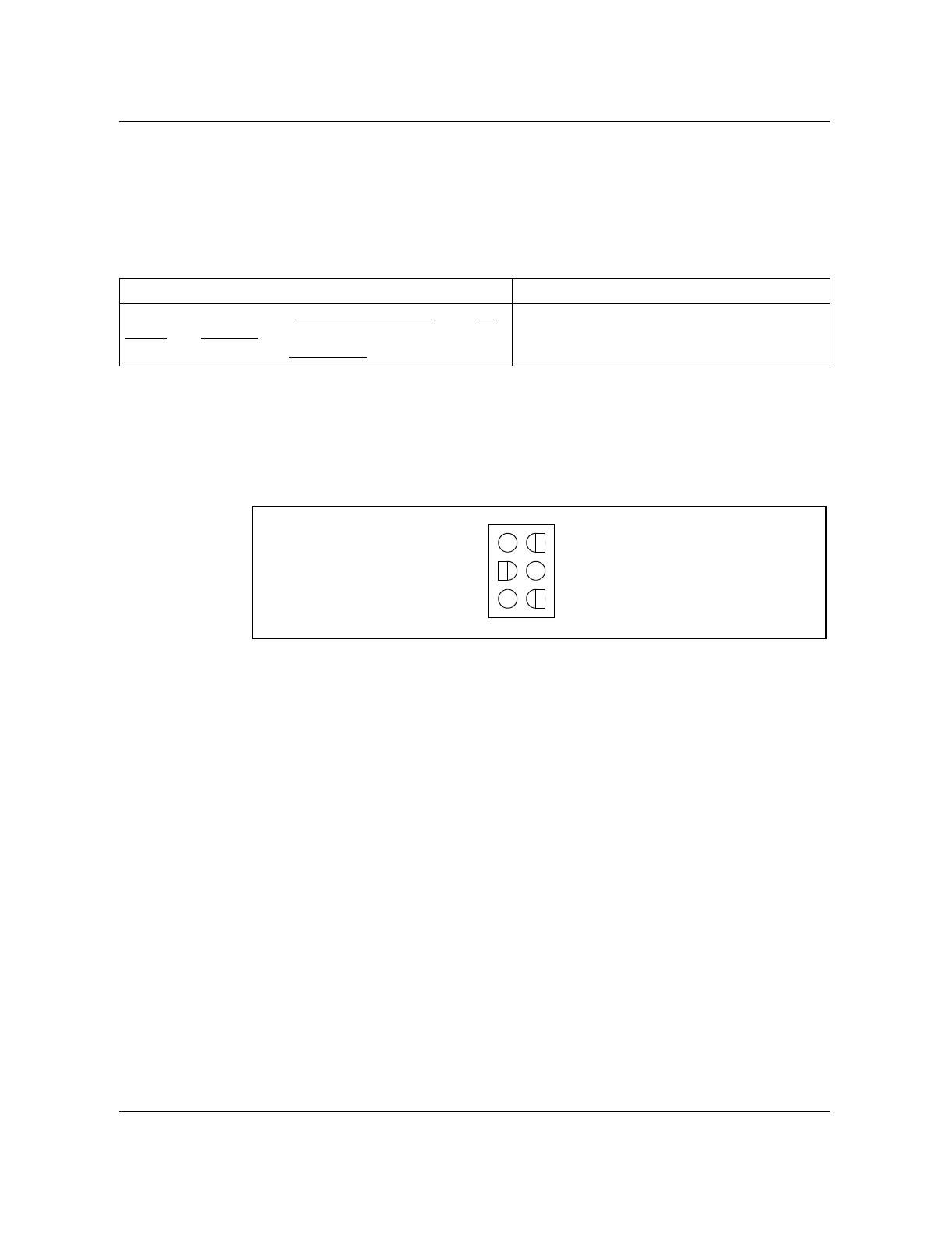
CE and RF frames 4-5
Wireless Solutions TDMA 1900 Macrocell Cell Site Maintenance Manual MTX08
Frame and equipment voltage checks
Verifying frame and equipment voltages is a good preventative check that can
ensure proper cell site performance. Follow the procedure in Table 4-4 to
verify the frame voltage and polarity.
Refer to Figure 4-4, Table 4-5, Table 4-6, Table 4-7, Table 4-8, Table 4-9, and
Table 4-10 for voltage measurement pin locations for the CE and RF frame
equipment.
Figure 4-4
Power connector on ACU backplane.
Table 4-4
Frame voltage procedure
Action Observation
Measure and record the Voltage and Polarity of the A
power and B power terminals with respect to the dc
Return bar at the top of each frame (CE and RF).
+26.5 to 29 V dc
+‘A’ power
+‘B’ power
+Bias power
–‘A’ return
–‘B’ return
–Bias return

4-6 CE and RF frames
411-6201-500 Preliminary 03.03 July 1999
Table 4-5
VSMO input power connector (P3) signals
Table 4-6
RPDU power connector (J2) (6-pin Mate’n lock)
Table 4-7
RRM power connector on the RPDU (J9) (12-pin Mate’n lock)
Pin# Signal name Description
1+27 V–A +27 V dc ”A” power in
2+27 V–RETA +27 V dc ”A” power return
3+27 V–B +27 V dc ”B” power in
4+27 V–RETB +27 V dc ”B” power return
Pin# Signal
1+27 V dc “A”
2+27 V dc “B”
3A ground
4B ground
5-6 No connection
Pin# Signal
1RRM X dc power
2RRM X’ dc power
3RRM Y dc power
4RRM Y’ dc power
5RRM Z dc power
6RRM Z’ dc power
7RRM X dc return
8RRM X’ dc return
9RRM Y dc return
10 RRM Y’ dc return
11 RRM Z dc return
12 RRM Z’ dc return

CE and RF frames 4-7
Wireless Solutions TDMA 1900 Macrocell Cell Site Maintenance Manual MTX08
Table 4-8
LRM fan module (J10) (10-pin ribbon) on the RPDU
Pin# Signal
1+27 V dc “A”
2+27 V dc “A”
3+27 V dc “B”
4+27 V dc “B”
5dc return “A”
6dc return “A”
7dc return “B”
8dc return “B”
9Fan 1 alarm (Normal = +27 V dc,
alarm =< 1 V dc)
10 Fan 2 alarm (Normal = +27 V dc,
alarm =< 1 V dc)
Table 4-9
LRM (J3) power connector
Pin# Signal
1power
2return
Table 4-10
ICRM power connector
Pin# Signal
TB1 24 V dc

4-8 CE and RF frames
411-6201-500 Preliminary 03.03 July 1999
5-1
Wireless Solutions TDMA 1900 Macrocell Cell Site Maintenance Manual MTX08
5Very Stable Master Oscillator (VSMO)
tests
Very Stable Master Oscillator (VSMO)
Cell site transceivers require a stable reference in order to accurately produce
transmit carrier frequencies and to select receive frequencies. The VSMO
produces this stable reference for the Transmit Receive Units (TRUs) to
ensure that all channels operate on their assigned frequencies and do not
interfere with other channels. Therefore the VSMO should be tested once
each year.
Master Oscillator power and frequency test
Follow the steps in Table 5-1 for the oscillator test procedures. See Figure 5-1
and Table 5-2 for IFR test set up.
Attention
Measurement discrepancy
When using the Power Meter on the IFR 1900, the
signal reading was 5.8–6.3 dB lower than the
Spectrum Analyzer value.
Table 5-1
VSMO test procedures
Step Action Observation
1Connect the communications monitor to the
output port on the back of the VSMO. SMA to N type cable required.
2Measure the output of the master oscillator
and record on the test form. 8.2dBm ±2.6dB
3Observe and record the RF frequency /
frequency error 4.8 MHz ±0.085 ppm
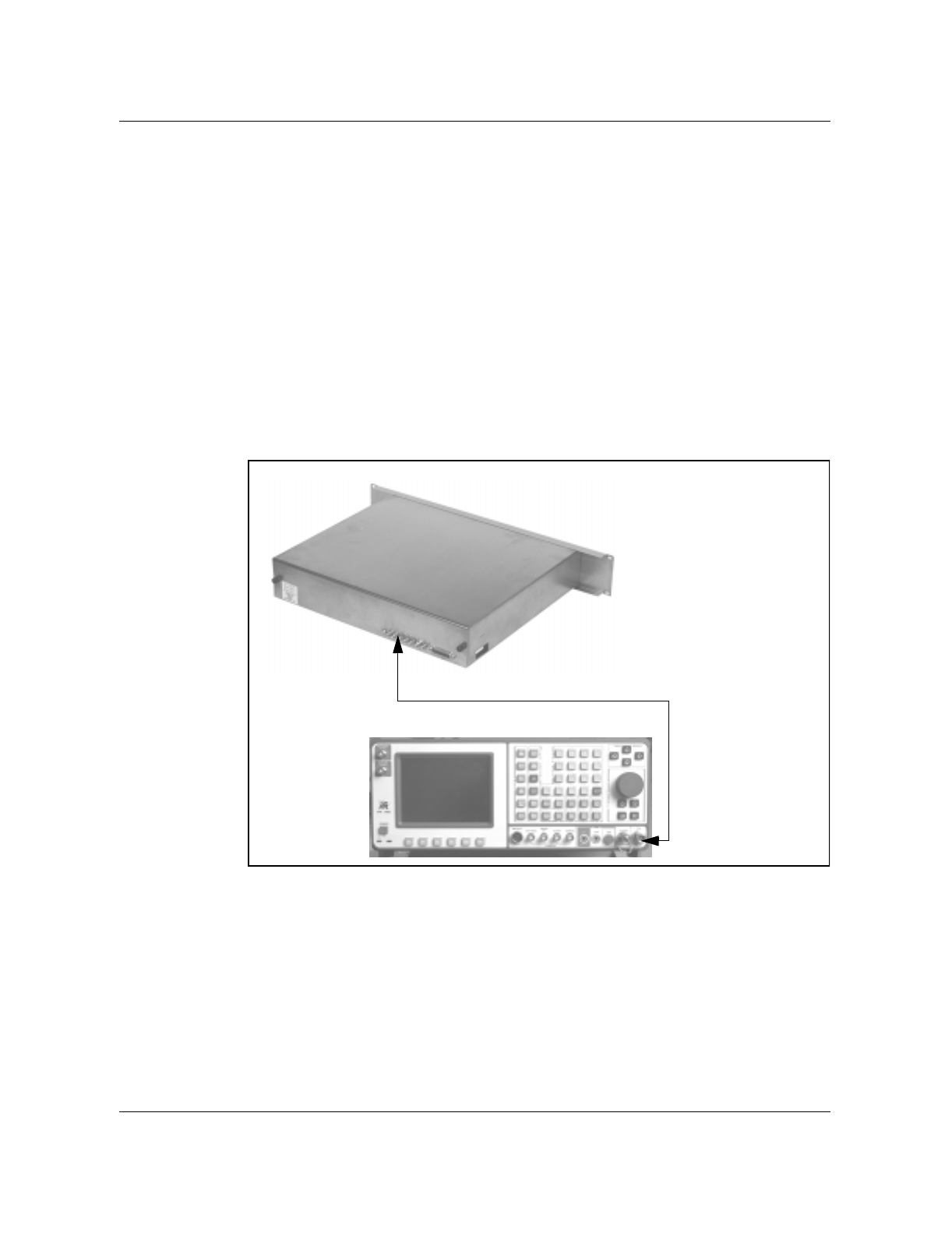
5-2 Very Stable Master Oscillator (VSMO) tests
411-6201-500 Preliminary 03.03 July 1999
Note 1: All unused ports should be terminated with 50-ohms for a correct
power reading.
Note 2: The VSMO is adjusted at the factory for frequency accuracy. If
the frequency test fails it must be replaced with a new unit.
Note 3: The recommended frequency counter is a:
HP 53132 A 225 MHz Universal Frequency Counter
An external 10 MHz reference into the frequency counter must be used in
order to ensure measurement accuracy (ensure external/internal reference
switch is selected to "external"). Any one of GPS, rubidium, or cesium
references may be used, or any reference that meets a minimum stability
requirement of +/- 1 x 10 -9( +/- 1 ppb). Ensure that prior to usage, that
the external frequency reference has stabilized/warmed up according to
the manufacturer's specifications and requirements.
Figure 5-1
Oscillator power level and frequency test setup
Oscillator outputs
T/R connector
Test cable
IFR 1900
VSMO

Very Stable Master Oscillator (VSMO) tests 5-3
Wireless Solutions TDMA 1900 Macrocell Cell Site Maintenance Manual MTX08
Note: For IFR operation refer to the “Appendix A” in this manual.
Table 5-2
IFR set up for VSMO test
IFR field Data
Set Rcvr Freq 4.8000 Mhz
Select Mod FM3
Select Rcvr In T/R
Select Input Atten 0 dB
Select AGC Type Auto
Rcvr Out Speaker off
Rcvr Out Audio off
Rcvr Out Demod Out off
Auto Volume Level off
Operation Mode Direct
Signaling Formats Digital

5-4 Very Stable Master Oscillator (VSMO) tests
411-6201-500 Preliminary 03.03 July 1999
6-1
Wireless Solutions TDMA 1900 Macrocell Cell Site Maintenance Manual MTX08
6Antenna and Transmission line tests
Antenna direct current continuity
These tests are required for new antennas or antennas suspected of faulty
operation. These tests are service affecting.
The most important consideration of antenna direct current continuity is not
so much the antenna but the transmission line shield. Of course, the antenna
must be electrically connected to the coaxial transmission line, but most
important, the transmission line shield must be grounded for lightning
protection.
The other dc tests serve as more of a record of the resistance of the shield and
center conductor. They may indicate future grounding problems or identify a
change in the antenna dipole condition (open, now shorted or vice versa).
Follow Table 6-1 for the antenna direct current continuity test.
CAUTION
RF Radiation Hazard
All transceiver transmitters must be turned off
before disconnecting or connecting transmit cables
to avoid RF induced injuries.
CAUTION
Service Disruption
The following tests are service affecting when the
antenna is disconnected.
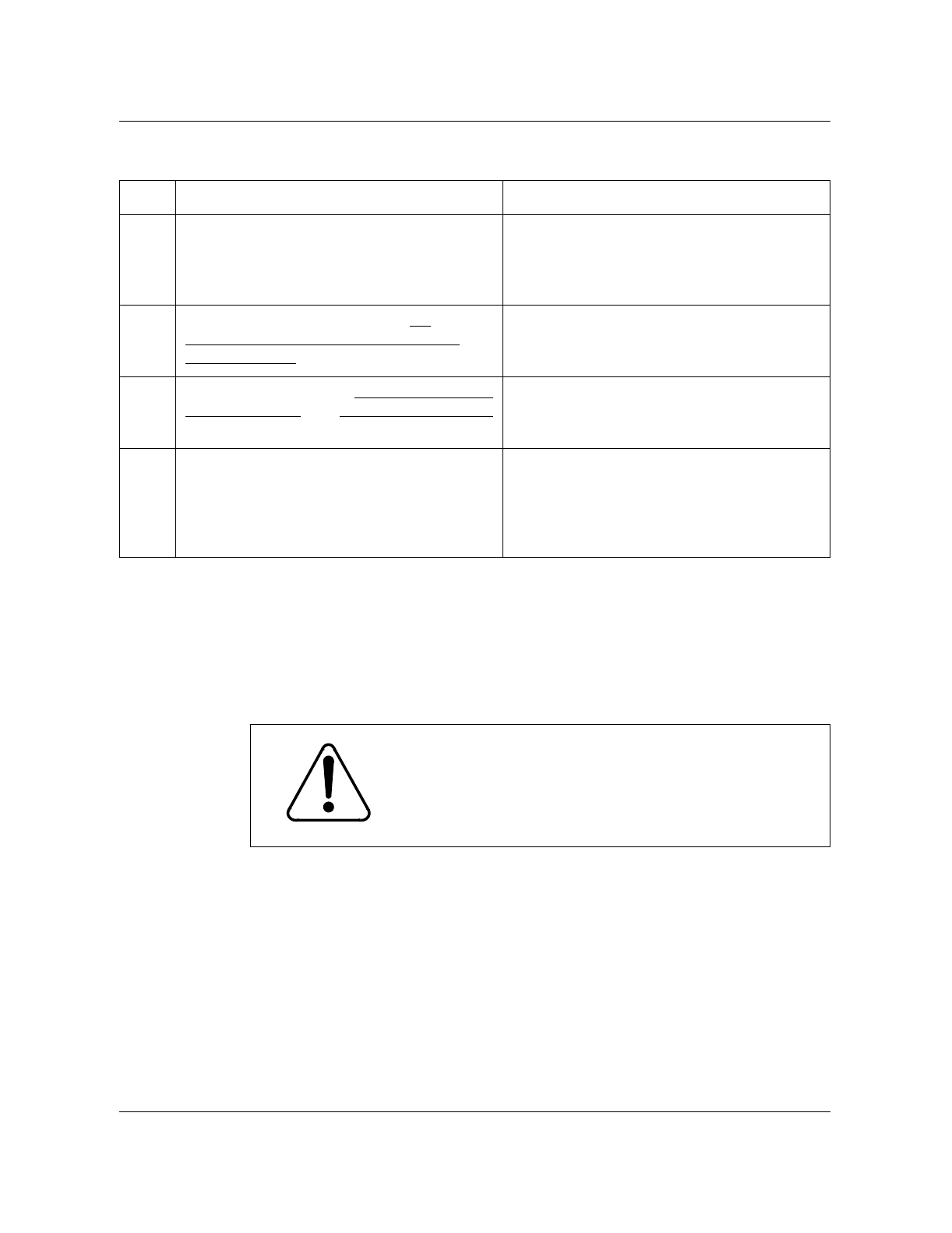
6-2 Antenna and Transmission line tests
411-6201-500 Preliminary 03.03 July 1999
Table 6-1
Direct current continuity test
Antenna return loss
The antenna return loss is measured to verify that the antenna is properly
matched to the system and to identify open connectors. This test uses the
signal generator, the spectrum analyzer and the VSWR bridge to sweep the
antenna for return loss at both the receive (1850 to 1910 MHz) and transmit
(1930 to 1990 MHz) frequency bands.
Test equipment: RF Signal Generator
Spectrum Analyzer
VSWR Bridge
If any of the test equipment is not available, a Thruline Wattmeter may be
used.
Refer to Figure 6-1 and Table 6-2 for antenna return loss test set up diagram
and test procedure.
Step Action Observation
1Visually inspect the bonding of the
transmission line to the mast ground riser at
both the top and bottom of the tower.
The transmission line must be bonded at
both the top and bottom. A set of binoculars
or a spotting telescope may be required to
verify the upper bonding.
2Inside the building, measure the dc
resistance of the outer conductor to the
principle ground.
Less than or equal to 0.5 Ω
3Measure and record the dc resistance of the
center conductor (pin) to the outer conductor
(shield).
4Also check the alignment of the center pin of
the heliax connector. If necessary re-align
the centre pin so that the female pin in the
antenna jumper cable connector is not
damaged.
Repair or replace heliax, connectors, ground
systems as required.
CAUTION
Service Disruption
The following tests are service affecting when the
antenna is disconnected.
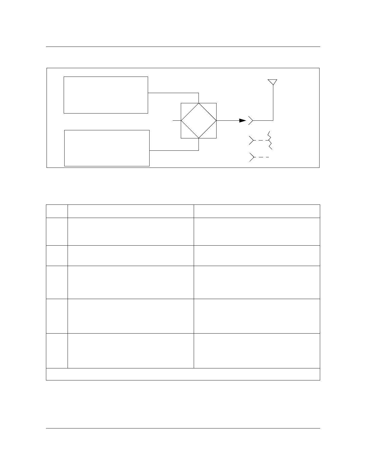
Antenna and Transmission line tests 6-3
Wireless Solutions TDMA 1900 Macrocell Cell Site Maintenance Manual MTX08
Figure 6-1
Antenna return loss block diagram
Antenna return loss test
Table 6-2
Antenna return loss test procedure
Step Action Observation
1Connect the signal generator, the spectrum
analyzer and a 50 ohm load to the VSWR
bridge.
See Figure 6-1.
2Set the signal generator output level to 0
dBm.
3With the Device under Test (DUT) VSWR
bridge port connect to an open, adjust the
display on the spectrum analyzer to the top
of the screen.
4Connect a 50 ohm termination to the open
port on the VSWR bridge and step the
generator through the receive and transmit
band to verify the test set-up for return loss.
Return loss should be greater than 35 dB
over the bands.
5Remove the termination from the VSWR
bridge, connect the antenna jumper cable to
the open port and again step the generator
across the transmit and receive bands.
-sheet 1 of 2-
Signal generator
1850 - 1910 MHz Rx
1930 - 1990 MHz Tx
Spectrum analyzer
VSWR
bridge
50¾
Load
internal
DUT
50-ohm
Termina
Open
tion
6-4 Antenna and Transmission line tests
411-6201-500 Preliminary 03.03 July 1999
Thruline Wattmeter method (antenna return loss)
This is a service affecting test using a Thruline Wattmeter. It can be used with
transmit antennas only.
Follow steps in Table 6-3.
6Record the minimum return loss of the
antenna and transmission line in the system. Return loss: 1850 to 1910 MHz Rx
1930 to 1990 MHz Tx
The return loss typically should be 3 or 4 dB
greater then the antenna return loss as
stated by the antenna manufacturer.
7Repeat the test for each antenna installed for
the cell site.
8If the test fails, check the antenna matching,
cables and connectors.
CAUTION
RF Radiation Hazard
All transceiver transmitters must be turned off
before disconnecting or connecting transmit cables
to avoid RF induced injuries.
Table 6-3
Thruline wattmeter method
Step Action Observation
1Connect the Thruline Wattmeter between the
duplexer and the antenna.
2Measure the forward and reverse power
using the appropriate element with one or
more transmitters turned on.
Reflected power less than 4% of forward
power
Table 6-2
Antenna return loss test procedure (continued)
Step Action Observation
-sheet 2 of 2-

Antenna and Transmission line tests 6-5
Wireless Solutions TDMA 1900 Macrocell Cell Site Maintenance Manual MTX08
Antenna sweep
Measure the reflected power from the antenna across the entire cellular band
(receive and transmit) to check for hidden damage or deterioration of the
antennas.
Follow the procedure in Table 6-4 for the antenna sweep test.
Table 6-4
Antenna sweep procedure
Step Action Observation
1Set up and calibrate a network analyzer
(HP8753C or equivalent) to sweep 1850 to
1990 MHz.
2Notify the Control Center to OFFLINE the
cell site.
3Connect the network analyzer to the antenna
transmission line.
4Perform a return loss sweep on the Network
Analyzer. Note the worst frequencies by
placing 2 markers each on the transmit and
receive frequencies. then print a hard copy of
the upper left quadrant.
Measured return loss of the antenna can be
calculated as:
RL (ant) = -14 dB - 2 times the antenna
cable loss
or:
Compare you results with that of the RF Path
calculated return loss of the cell site logbook
(check the RF PAth Analysis sheet).
If the results are bad compared to the log
book values connect the test cable directly to
the main transmission line and resweep.
It is possible to have a bad jumper. If the
results are still bad then the problem could
be either with the transmission line or the
antenna.
5Do a TDR sweep of the antenna. Print a hard
copy of the lower left quadrant.
6Do a SWR sweep of the antenna. Print a
hardcopy of the upper quadrant. The result
should not be higher than 1.5:1
-sheet 1 of 2-

6-6 Antenna and Transmission line tests
411-6201-500 Preliminary 03.03 July 1999
VSWR monitor deployment
Refer to the “VSWR monitor deployment” section in TDMA 1900 RF
Deployment Guide, 411-6201-200.
7Do a Smith Chart of the antenna. Print a
hard copy of the lower right quadrant. The
results must be close to 50 ohms (±50
ohms).
8Reconnect all the jumpers to their proper
location then inform the Control Center to
RTS the cell site.
If the transmit antenna is bad and the receive
antenna is good on the transmit band,
restore service by using the receive antenna
until the transmit antenna is repaired.
Table 6-4
Antenna sweep procedure (continued)
Step Action Observation
-sheet 2 of 2-
7-1
Wireless Solutions TDMA 1900 Macrocell Cell Site Maintenance Manual MTX08
7Tx insertion loss test
Overview
Check the transmit insertion loss once a year. The AutoTune Combiners
(ATC) require no periodic maintenance. For a complete functional description
refer to TDMA 1900 Macrocell RF Frame Description, 411-6201-113.
If an alarm exists, perform the ATC troubleshooting procedure as described in
Chapter 3, Troubleshooting at the cell site, in TDMA 1900 Macrocell
Troubleshooting Guide, 411-6201-500.
Transmit insertion loss test
The purpose of the forward path insertion loss test is to verify the
performance of the ATC, duplexer transmit (forward) filter, and all RF cables
and connection between the TRU and the duplexer antenna connector. The
test involves measuring the RF power output at the duplexer antenna
connector for each TRU/PA pair, then comparing that power measurement to
the power measurement taken at the PA RF output connector. The difference
between the two measured power levels should be less than 4.9 dB. This test
also will verify SCLPA output power.
CAUTION
RF Radiation Hazard
DO NOT disconnect an RF cable from the ATC if
there is RF power applied to that cable.
CAUTION
Damage to Test Equipment
Be aware of and adhere to the signal input limits of
all test equipment used in these procedures.

7-2 Tx insertion loss test
411-6201-500 Preliminary 03.03 July 1999
Combiner insertion loss–power method
This test verifies the loss from the power amplifier output to the antenna port
of the duplexer. It also verifies that the return loss of the isolator is within
specifications. The loss characteristic is verified by comparing the power
output measured at the duplexer antenna (ANT) port with the power output
measured directly from the power amplifier. Refer to procedure in Table 7-1
and Figure 7-1.
Table 7-1
Tx insertion loss procedure
Step Action Observation
1Place the cell site out of service at the MTX
using the "MANBUSY" command.
2Setup the communications monitor to
measure the power of the on-frequency Tx
carriers. For IFR setup refer to Appendix A in
this manual.
3Connect a video terminal to the TRU used for
this test. Set up the terminal as per the
terminal setup procedure. (See Chapter 2 in
this manual for terminal interface setup).
4Connect the RF input of the communications
monitor (T/R) to the SMA connector on the
PA output cable of the TRU to be tested.
5Set up the TRU for Tx power checks:
• set max power level = 45.5dBm
• set power step = 4 dB
• power step level = 0
Set to the assigned channel (same as IFR).
Turn the PA on.
Carrier: ON
6Measure the max power output level at the
SMA connector of the PA output. Note the power output level.(45.5 dBm)
7Turn the PA off and then restore the RF
cabling. Carrier: OFF
8Connect the RF input (T/R) of the
communications monitor (IFR) to the
duplexer antenna port. See Figure 7-1 for the
test set-up.
Note: Ensure only one TRU is transmitting
due to the IFR power handling capabilities.
-sheet 1 of 2-

Tx insertion loss test 7-3
Wireless Solutions TDMA 1900 Macrocell Cell Site Maintenance Manual MTX08
9Turn the PA on and measure the power
output at the antenna port of the duplexer. Maximum loss between the PA output cable
and the antenna port of the duplexer must
not exceed 4.9 dB.
10 Record value
11 Turn the PA off. Carrier: OFF
12 If the power level output loss is out of spec.,
refer to
TDMA 1900 Troubleshooting Guide,
411-6201-501.
13 Repeat this test for the remaining Tx paths.
14 Reconnect all cables.
Table 7-1
Tx insertion loss procedure (continued)
Step Action Observation
-sheet 2 of 2-
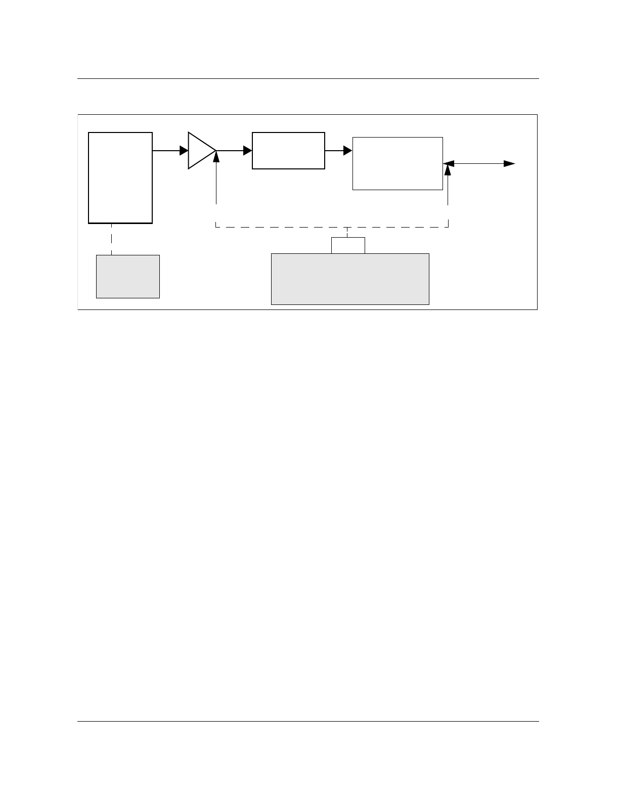
7-4 Tx insertion loss test
411-6201-500 Preliminary 03.03 July 1999
Figure 7-1
Power measurement diagram
Note: Maximum loss is shown, if the loss is greater than 4.9 dB
troubleshoot the ATC, cables and duplexer. Refer to the TDMA 1900
Macrocell Troubleshooting Guide, 411-6201-501.
Transceiver
Tx
Rx
SCLPA
Combiner
Shelf
Tx
Rx
Ant
To Rx/Tx
Antenna
45.5 dBm 40.6 dBm
IFR 1900
(or equivalent)
T/R
Terminal
Interface
Duplexer
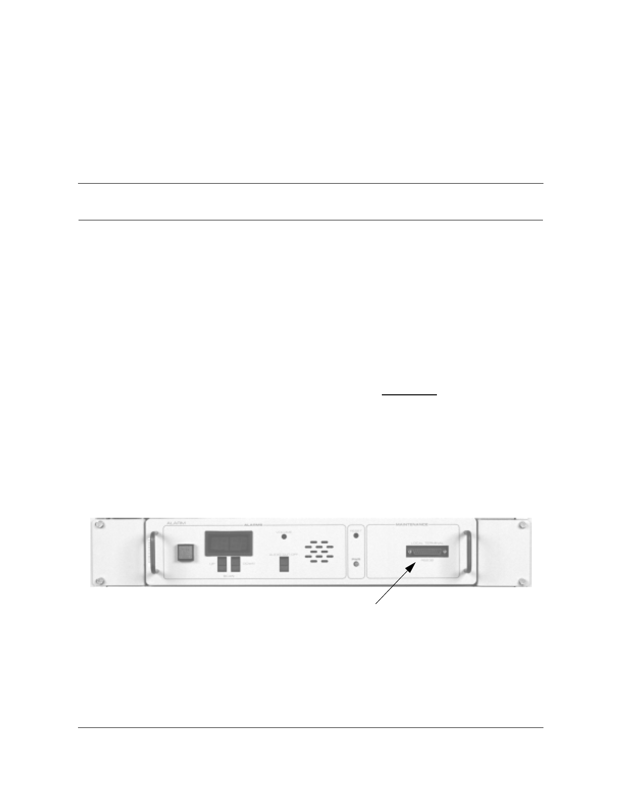
8-1
Wireless Solutions TDMA 1900 Macrocell Cell Site Maintenance Manual MTX08
8ACU tests
Overview
Alarm Control Unit (ACU)
The Alarm and Control Unit (ACU) provides discrete alarm monitoring,
reporting and control functions at a cell site. The site ACU concentrates all
alarm input points at the cell site and updates the MTX of any status change
over redundant data links. The MTX can also poll for the condition of the
ACU and request current status information or change the status of any output
control contact. For a complete description of the ACU, refer to TDMA 1900
Macrocell CE Frame Description, 411-6201-112.
The ACU alarm input points for equipment such as fans, over-temperature
alarms and door switches should be verified once a year. Alarm output
contacts and alarm reactions should be verified at the same time.
The MAINTENANCE (Local Terminal) port located on the front of the ACU
gives direct access to the ACU MPU (microprocessor) board. You can use this
interface to configure and monitor the alarm input points and the control
output contacts. A photo of the ACU is shown in Figure 8-1.
Figure 8-1
ACU front panel
Local terminal port

8-2 ACU tests
411-6201-500 Preliminary 03.03 July 1999
ACU test setup
Connect a VT100 terminal (or equivalent) using a null modem cable to the
ACU local terminal connector. Setup the terminal as described in Table 8-1.
Should you be unable to set the terminal to the settings listed, the ACU
configuration can be changed by setting the local terminal switch (SW3) on
the MPU board to match your terminal settings. Refer to Table 4-6 for the
settings of SW3 in TDMA 1900 Macrocell CE Frame Description, 411-6201-
112.
Once the terminal and ACU are set properly, connect the terminal to the
MAINTENANCE port with a null modem cable.
Table 8-1
ACU test setup procedure
Step Action Observation
1Set up the terminal as per the requirements
to the right. BAUD Rate: TX 9600
RX 9600
Scroll: smooth
Auto repeat: on
ANSI
Auto Wrap: off
Receiver Parity: ignore
Parity: disabled
Character Bits: 8 bits
Interface: on
Scroll Key: VT100
Form Feed: line feed
Control Characters: executed
Local Echo: off
RTS-CTS Handshake: off
8 Bits Tx: space
2Power up the terminal, hold down the
CONTROL key and press the Z key.
Press the RESET key on the ACU to activate
the Maintenance Screen on the terminal.
The CS ACU Maintenance Screen (Figure 8-
3) will appear.
3Using the keyboard arrows, select the Input
and Monitor menu items on the screen. Verify the remote alarms per the site alarm
records.
-sheet 1 of 2-

ACU tests 8-3
Wireless Solutions TDMA 1900 Macrocell Cell Site Maintenance Manual MTX08
4Test all equipped alarm points on the ACU.
This can be done by turning the appropriate
DC breaker OFF, removing fuses,
connectors, opening doors, etc.
Note:
Some of these steps may be service
affecting.
Bold display - alarm ON
Normal display - alarm OFF
5Apply +27 Vdc to each equipped alarm input
at the rear of the ACU. Verify that each alarm
indicates the correct status on the VT100
screen.
Bold display - alarm ON
Normal display - alarm OFF
6Open and close each selected output and
verify its action by observing an open or
short on the rear output connector, J8.
7The MAP technician should verify that the
correct alarms and logs are generated at the
MTX as the site technician activates alarm
conditions. Similarly, the cell site technician
should ensure that the audible and LED
alarm indicators on the ACU properly report
the activation of the alarm conditions.
Table 8-1
ACU test setup procedure (continued)
Step Action Observation
-sheet 2 of 2-
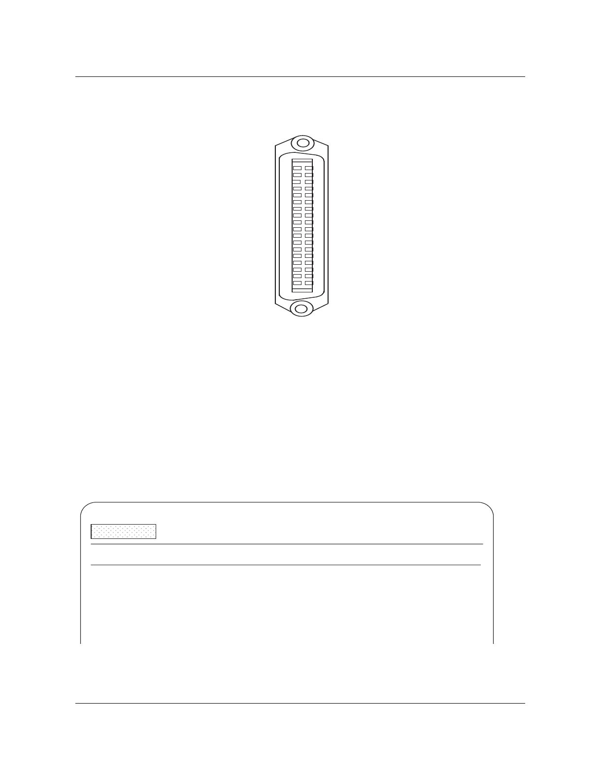
8-4 ACU tests
411-6201-500 Preliminary 03.03 July 1999
A typical alarm connector pinout is shown in Figure 8-2.
Figure 8-2
Typical alarm connector (36-pin)
Using the ACU maintenance terminal
A menu of options will appear on the screen as shown in Figure 8-3.
There are four primary options at the first level to choose:
• input
• output
• general
• analog ins (not used)
Each option consists of up to three lines on the screen. Figure 8-4 shows the
structure of these options.
Figure 8-3
Initial screen display
SLOT ALM PT 1
SLOT ALM PT 3
SLOT ALM PT 5
SLOT ALM PT 7
SLOT ALM PT 9
SLOT ALM PT 11
SLOT ALM PT 13
SLOT ALM PT 15
ALARM +BIAS
SLOT ALM PT 17
SLOT ALM PT 19
SLOT ALM PT 21
SLOT ALM PT 23
SLOT ALM PT 25
SLOT ALM PT 27
SLOT ALM PT 29
SLOT ALM PT 31
ALARM +BIAS
1
2
3
4
5
6
7
8
9
10
11
12
13
14
15
16
17
18
19
20
21
22
23
24
25
26
27
28
29
30
31
32
33
34
35
36
SLOT ALM PT 2
SLOT ALM PT 4
SLOT ALM PT 6
SLOT ALM PT 8
SLOT ALM PT 10
SLOT ALM PT 12
SLOT ALM PT 14
SLOT ALM PT 16
ALARM +BIAS
SLOT ALM PT 18
SLOT ALM PT 20
SLOT ALM PT 22
SLOT ALM PT 24
SLOT ALM PT 26
SLOT ALM PT 28
SLOT ALM PT 30
SLOT ALM PT 32
ALARM +BIAS
Cell-Site ACU Local
Terminal
Monitor Enable Disable Alarms Setbase Calcbase Rev_Amb Help
1st l
2nd
line
3rd
l
Analog Ins Input Output General (use arrow keys to select) HH:MM
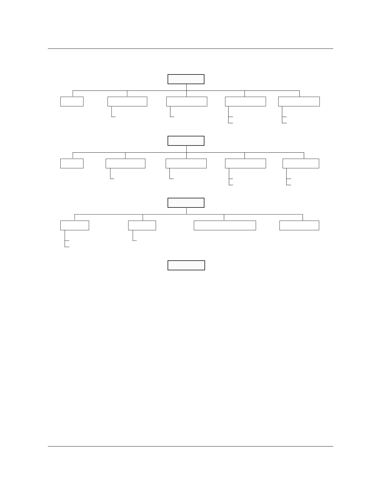
ACU tests 8-5
Wireless Solutions TDMA 1900 Macrocell Cell Site Maintenance Manual MTX08
Figure 8-4
ACU menu structure
Selecting an option
The procedure for selecting an option and setting the parameters for that
option are as follows (the ‘Enable Single’ in the Input option is described as
an example):
Note: The left and right arrow keys move the cursor to options on the
same line. The up arrow key moves the cursor back to the previous line
and down arrow key moves the cursor to the next line.
1. On the first line, move the cursor to the Input option by pressing the right
arrow key. The options on the second line will change accordingly as the
cursor is moved.
2. Use the down arrow key to move the cursor to the second line. The cursor
will always highlight the first option on the second line.
3. On the second line, move the cursor to the Enable Single option by
pressing the right arrow key. The options on the third line will change
accordingly as the cursor is moved.
4. Use the down arrow key to move the cursor to the third line. The cursor
will always highlight the first option on the third line.
Analog Ins
Input
Monitor Enable Single Disable Single Enable Range Disable Range
Alarm Input: Alarm Input: From:
To: From:
To:
Output
Monitor Open Single Close Single Open Range Close Range
Control Output: Control Output:
General
Set Clock Restart Show Function Codes Firmware Info
Warm start (0) or
Totally reboot (1):
Hours:
Minutes:
From:
To:
From:
To:
(No longer supported)

8-6 ACU tests
411-6201-500 Preliminary 03.03 July 1999
5. On the third line, type in the number of the alarm input point that needs to
be enabled and press the Return key.
Note: For options that have more than one parameter on the third line, use
the left and right arrow keys to move the cursor from one parameter to
another parameter.
6. Press the Return key a second time to execute the selected parameters of
the option. The display will show:
Command Sent...Acknowledge Received
7. Move the cursor back to the previous line by pressing the Up arrow key.
Note: The ‘Monitor’, ‘Show Function Codes’ and ‘Firmware Info’
options do not have a third line on the menu. When selecting these
options, press the Return key after they are selected. The information for
these options will appear on the display.
Input option
Five functions can be selected under the Input option:
• Monitor
• Enable Single
• Disable Single
• Enable Range
• Disable Range

ACU tests 8-7
Wireless Solutions TDMA 1900 Macrocell Cell Site Maintenance Manual MTX08
Monitor
This function monitors the status of each alarm input point. Figure 8-5 shows
a typical Input Monitor screen display.
Figure 8-5
Typical input monitor screen display
• Alarm point 241—ROM check
• Alarm point 242—RAM check
• Alarm point 243—Non-volatile RAM check
• Alarm points 244 to 248—Reserved
For the assignment of the external input alarm points, refer to Table 4-4 in
TDMA 1900 Macrocell CE Frame Description, 411-6201-112.
Cell-Site ACU Local Terminal
Monitoring Inputs...
Analog Ins Input Output General (use arrow key to select) HH:MM
Monitor Enable Single Disable Single Enable Range Disable Range
Disable/Inactive Enable/Inactive Disable/Active Enable/Active
1 2 3 4 5 6 7 8 9 10 11 12 13 14 15 16 <-- Slot 1
17 18 19 20 21 22 23 24 25 26 27 28 29 30 31 32 <-- Slot 2
33 34 35 36 37 38 39 40 41 42 43 44 45 46 47 48 <-- Slot 3
49 50 51 52 53 54 55 56 57 58 59 60 61 62 63 64 <-- Slot 4
65 66 67 68 69 70 71 72 73 74 75 76 77 78 79 80 <-- Slot 5
81 82 83 84 85 86 87 88 89 90 91 92 93 94 95 96 <-- Slot 6
<-- Slot 7
<-- Slot 8
<-- Slot 9
<-- Slot 10
<-- Slot 11
<-- Slot 12
<-- Slot 13
<-- Slot 14
<-- Slot 15
241 242 243 244 245 246 247 248 <-- ACU Internal Alarm Points

8-8 ACU tests
411-6201-500 Preliminary 03.03 July 1999
The status of each point is displayed as follows (see Figure 8-5 for the screen
display):
• Disable/Inactive The alarm input point has been disabled either
from the MTX or the terminal and is currently not
detecting an alarm.
• Enable/Inactive The alarm input point has been enabled and is
currently not detecting an alarm.
• Disable/Active The alarm input point has been disabled. It is
currently detecting an alarm which, because it is
disabled, will not be reported to the MTX.
• Enable/Active The alarm input point has been enabled. It is
currently detecting an alarm that has been reported
to the MTX.
You can monitor the status of the alarms continuously since the display is
automatically updated every second while in the Monitor mode.
After you leave the Monitor function, the data will still be displayed until the
RETURN key is pressed.
Enable Single
The Enable Single function enables input alarm points one at a time. An input
alarm point must be enabled before it will report alarm conditions to the
MTX.
Disable Single
The Disable Single function disables input alarm points one at a time. An
input alarm point which is disabled will not report alarm conditions to the
MTX.
Enable Range
The Enable Range function enables a group of input alarm point at a time.
Disable Range
The Disable Range function disables a group of input alarm point at a time.
Output option
Five functions can be selected under the Output option:
• Monitor
• Open Single
• Close Single
• Open Range
Close Range.

ACU tests 8-9
Wireless Solutions TDMA 1900 Macrocell Cell Site Maintenance Manual MTX08
Monitor
This function monitors the status of each output contact point. Figure 8-6
shows a typical Output Monitor screen display.
Figure 8-6
Typical output monitor screen display
For the assignment of the output contact points, refer to Tables 4-3 in TDMA
1900 Macrocell CE Frame Description, 411-6201-112.
HH:MM is the ACU clock display. It is updated once a minute.
The status of each point is displayed as follows (see Figure 8-6 for the screen
display):
• Open The output contact is open.
• Closed The output contact is closed.
You can monitor the status of the output contacts continuously since the
display is updated whenever an output contact is opened or closed.
After you leave the Monitor function, the data will still be displayed until the
RETURN key is pressed.
Open Single
The Open Single function opens output contact points one at a time. An
output contact point is disabled when it is set to Open.
Close Single
The Close Single function closes output contact points one at a time. An
output contact point is enabled when it is set to Closed.
Cell-Site ACU Local Terminal
Monitoring Outputs...
Analog Ins Input Output General (use arrow key to select) HH:MM
Monitor Open Single Close Single Open Range Close Range
Open Closed
<-- Slot 16
<-- Slot 15
17 18 19 20 21 22 23 24 <-- Slot 14
<-- Slot 13

8-10 ACU tests
411-6201-500 Preliminary 03.03 July 1999
Open Range
The Open Range function opens a group of output contact points at a time.
Close Range
The Close Range function closes a group of output contact points at a time.
General option
Three functions can be selected under the General option.
•Set Clock
•Restart
• Show Function Codes
Firmware Info.
Set Clock
The ACU clock determines the time alarms are generated. You can set the
time on a 24-hour basis by using this option. From the map terminal at the
MTX.
Restart
This function restores the alarm input points and output contacts of the ACU
to the default states.
Show Function Codes
This function displays the function codes the system uses on messages
between the MTX and the ACU.
ACU front panel display
A red four digit LED display indicates the status of the input points. Only
alarms from enabled inputs will be reported; a disabled Input will not alarm.
The display shows the Input point by the number of the last active alarm. For
example, a flashing [167] indicates that Input point #167 -RRMX ALARM-
is active (in alarm state). The display will flash until acknowledged by
pressing either the UP or DOWN button. All the active alarm points can then
be scrolled with the UP and DOWN buttons. When an Input point returns to
the inactive (normal) state, the Input point number will no longer be
displayed. Inactive or disabled input points do not display on the front panel.
An Input point is enabled or disabled from the local terminal or DMS–MTX
interface. Similarly, status of the output contacts can only be obtained from
either the local terminal or DMS–MTX interface.
Audible alarm
A Sonalert type of audible indication is provided at the ACU. This alert
sounds on every new alarm, and continues until silenced by the operator.

ACU tests 8-11
Wireless Solutions TDMA 1900 Macrocell Cell Site Maintenance Manual MTX08
Front panel controls
SCAN: The UP/DOWN buttons allow the maintenance
UP/DOWN personnel to scan through all the enabled alarm
points which are currently active (in alarm state). The
alarm point numbers are displayed on the LED display.
Note: Input points must be enabled to alarm or be displayed.
AUDIO CUT-OFF This momentary-close switch acknowledges the alarm
and silences the audible indication. The ACU is silenced
but will sound again if any more alarms occur.
VOLUME This recessed potentiometer control adjusts the sound
volume of the audible alarm.
RESET The RESET switch is a momentary-close push button
that is recessed in the front panel to ensure it is not
pressed by accident. This is a forced hardware reset of
the ACU.
PWR This green LED indicates the ACU is powered.
Firmware Info
You can display information about the existing firmware load in the ACU.
DMS–MTX I/O Point Numbering
The Input and Output points in the DMS–MTX
datafill tables ACUALM and ACUCTRL are
shown numerically one point lower than in the
ACU.
For example: Alarm input point 10 in the ACU
corresponds to point 09 in the ACUALM table.

8-12 ACU tests
411-6201-500 Preliminary 03.03 July 1999

9-1
Wireless Solutions TDMA 1900 Macrocell Cell Site Maintenance Manual MTX08
9Miscellaneous equipment tests
RRM (Remote Receive Module)
There are no operational tests for the Remote Receive Module (RRM) at the
cell site. If you want to check the operation of the RRM, refer to TDMA 1900
Macrocell Troubleshooting Guide, 411-6201-501.
LRM (Local Receiver Module)
The LRM primary function is to amplify receive band signals received from
the antenna/RRM prior to distribution to the splitters and coaxial cables
which connect to the transceiver shelves.
Rotating the LRM attenuator switches on both LRM’s (LRM X and LRM X’)
should cause the RSSI to change by approximately 1/2 dB per setting. The
total range of the switch settings is approximately 6 dB. The function of the
switch is to introduce a specific level of attenuation to a receive path to
maintain a constant level across all receive paths. Refer to TDMA 1900
Macrocell Cell Site RF Deployment Guide, 411-6201-200.
There is no scheduled maintenance for the Local Receive Module. If you
suspect a fault in the LRM refer to TDMA 1900 Macrocell Troubleshooting
Guide, 411-6201-501.
RPDU (Receive Power Distribution Unit)
There are no operational tests for the RPDU at the cell site. If you want to
check the operation of the RPDU, refer to the TDMA 1900 Macrocell
Troubleshooting Guide, 411-6201-501.
ICRM (Intergrated Cellular Remote Module)
There are no operational tests for the Integrated Cellular Remote Module
(ICRM) at the cell site. If you want to check the operation of the ICRM,
contact the operator at the MTX for assistance. For a functional description
refer to TDMA 1900 Macrocell CE Frame Description, 411-6201-112.
Other equipment
CE and RF frame equipment not already specifically mentioned do not
require periodic maintenance.

9-2 Miscellaneous equipment tests
411-6201-500 Preliminary 03.03 July 1999
Transmission facilities
Transmission facilities include pressurized transmission lines, microwave
radio equipment and any copper facilities. It is important that your facilities
are in good condition, otherwise cell site performance might be
compromised. See recommended maintenance intervals from the
manufacturer for the specific equipment.
Microwave
Refer to the manufacturer’s instructions for periodic maintenance.
Transmission level and noise tests should be conducted once a year.
Copper Audio Link
The susceptibility of copper to noise and level problems requires more
frequent checks then digital or microwave facilities. Perform noise and level
checks quarterly on the T-1 transmission facilities.
Power
Clean, reliable power is essential to your cell site. The following are generic
periodic maintenance recommendations. Consult the manufacturer's
documentation for specific maintenance and specifications.
Acid safety equipment
Before you do anything in a liquid-electrolyte battery plant, make sure you have
proper acid-handling safety equipment available and in good condition. The
following equipment is recommended:
• face shield
• rubber gloves
• rubber apron
• eye wash station
• neutralizing powder and solution to clean up spills
BatteryGell cell batteries are virtually maintenance free. Liquid-electrolyte batteries,
however, require monthly maintenance refer to manufacturer's
recommendation. Each month:
• check the cell voltages and note any discrepancies; Increase the rectifier
output voltage from float voltage to equalizing voltage for 24 hours; If the
low cells are still low, replace them
• check electrolyte levels and top up with distilled water
• check exhaust system and hydrogen sensor (if equipped)

Miscellaneous equipment tests 9-3
Wireless Solutions TDMA 1900 Macrocell Cell Site Maintenance Manual MTX08
Rectifiers
Check the rectifier output voltage once a month refer to manufacturer's
recommendation. Check the high and low voltage alarm/cut-out sections once
a year.
Main generators
Some cell sites may not have access to public mains service; instead, they are
powered by on-site generators. At the very least you should:
• keep records of coolant and oil temperatures and operating times
• monitor fuel, oil and coolant levels
• follow manufacturer’s recommendations for oil and coolant changes and
periodic inspection and overhaul
Backup generators
Some sites will have backup generators. Every three months, verify that the
generators start and operate correctly by removing AC power from the cell site.
You should also:
• monitor fuel, oil and coolant levels and record operating times
• record generator readings
• follow manufacturer’s recommendations for oil and coolant changes and
periodic inspection and overhaul
Building service
If the building uses AC mains service from overhead poles, take a look at the
drop and service entrance once a year. Look for obviously damaged insulation
and threats from overhanging trees.
Cabling and connections
Whenever equipment is installed or changed, check the cabling and
connections. Take note of any suspect cables that give you problems from
time to time.

9-4 Miscellaneous equipment tests
411-6201-500 Preliminary 03.03 July 1999
Inside grounding
Inside grounding performs two functions: it prevents noise from one unit
getting into other equipment, and it ties all equipment together for protection.
Check for and repair any deterioration and corrosion of the grounding system,
you should also check to see that all new equipment installed in the building
is grounded properly. Refer to Power, Ground, and System Cabling for
TDMA 1900 Macrocell, IM 16-1753.
Frame bonding
Individual frames in a line-up should be bonded together with 3/8 inch or
larger bolts with star washers bearing on clean metal.
Ground cabling
Ground cables (battery return and chassis ground) run between each frame
and a customer-supplied common ground point. The specific number of
frames, and the type and location of customer-supplied power and ground
equipment, determines the detailed power and ground cabling requirements.
Site-specific power, ground, and system cabling information is provided in
the job specification documents and in the Interconnect Schematic (IS)
documents.
Check the ground for each frame, ensure that the frame ground cable (green)
from one of the frame ground points, runs to the site common ground point .
The cable must be #6AWG or larger. Ensure the cable is neat and observe the
minimum bend radius specifications.
Battery return cables connect to the CE frame and to the RF frames on a bus
bar in the RIP of each frame. In the RIP, the center (of three) bus bars is the
battery return bus bar. The cables run to the site common ground point. The
two battery return cables are connected to the battery return bus bar of the RF
frame RIP. Minimum size of the cable is #2/0AWG. Each cable is required to
carry approximately 110 Amps of current for a fully-provisioned frame.
Ensure the cables run to the site common ground point, and are connected to
the common ground point using the same technique and equipment as is used
for other cables at the common ground point.
Check all connections and ensure that new or changed equipment is properly
grounded. If there is a water pipe in the building, the principle ground bar
should be connected to it.
Transmission line entrance
The transmission line to the antennas should be lightning protected where it
comes into the building. Check the condition of the grounding connections
once a year and also following any severe lightning storm activity.

Miscellaneous equipment tests 9-5
Wireless Solutions TDMA 1900 Macrocell Cell Site Maintenance Manual MTX08
Outside grounding
A typical cell site, with its tall metal structures and antennas, is an open
invitation to a lightning strike. To avoid cell site degradation or total loss due
to electrical storm activity, inspect the grounding system just before the local
thunderstorm season. Checking the outside ground can be part of a site walk-
around check, also checking antennas, cables, structures, lighting and
foundations.
Tower and associated structures
Use a pair of binoculars or a spotting scope to verify that the air terminal
(lightning rod) and antennas are still attached to the tower and grounding
system. Verify that:
• the antenna feed cables are grounded at both ends
• the cables and clamps attaching the tower and waveguide bridge to the
grounding system are secure
• the cables and clamps connecting the guy wires to the grounding system
are secure
• transmission cables are grounded at both the top and the bottom of the
tower, and at the building entrance.
Building sheath, fences and other equipment
If the building has metal walls, roof or base, the metal components must be
grounded. The cell site fence and any fuel tanks or other metal structures must
be grounded as well. Check that the grounding cables and clamps are secure.
Antennas and tower
General structure
Detailed inspection of towers should be performed every one to three years by
an experienced inspector who can climb the tower and check all components.
Cell site maintenance personnel can perform an effective partial inspection
without leaving the ground, and this is recommended:
• once a year
• following a severe storm
• following a prolonged period of heavy icing
Use binoculars or a spotting scope if necessary. To perform a partial inspection:
• check the tower base for cracks, concrete break up and upheaval
• check all guy anchors for cracks or upheaval
• check guy tension and attachment
• check fasteners for security
• check all components for rust
• check for flaking paint (often a sign of over-stress)

9-6 Miscellaneous equipment tests
411-6201-500 Preliminary 03.03 July 1999
Tower lighting
At every visit visually confirm operation of the tower lights at the site after
dark. When the tower is climbed for structural inspection, the lights should be
thoroughly checked at the same time.
Grounding
Check all grounding that is accessible from the surface during your outside
grounding check for corrosion and damage. When the tower is climbed for
structural inspection, grounding on the higher parts of the tower should be
checked at the same time.
Paint
Painted towers need to be re-painted every few years. Check the over all
condition of the paint on an annual basis and re-paint as necessary.
Feed
Check that the transmission line is adequately supported and protected
between the cell site building and the antenna tower.
Antennas
When the tower is climbed for structural inspection, antennas should be
inspected as well. Check for:
• correct orientation and tilt
• crack, dents and burns
• fasteners, attachment and security
• transmission line and ground attachment security
• audible gas leakage in pressurized systems
Pressurized transmission lines
If a pressurized transmission line to the antenna is used, check the nitrogen
tank pressure and manifold pressure every visit. Check the dehydrator at the
same time.
Site performance
The ultimate measure of the condition of the cell site is the actual measured
performance. Site performance should be tested once a year and can be
gauged by the following tests. It should be taken into consideration that
coverage and handoffs can be impacted by seasons and weather.

Miscellaneous equipment tests 9-7
Wireless Solutions TDMA 1900 Macrocell Cell Site Maintenance Manual MTX08
Fringe coverage
Using the most recent coverage maps, take a test mobile and drive to the
fringe of the site coverage area with a call established to confirm coverage.
Most mobiles are able to access signal strength function mode.
Handoff checks
Using the “standard drive” defined for the site or system acceptance
procedures, drive across the cell boundaries with a call established. Confirm
that the handoffs occur in the appropriate places and that there is sufficient
hysteresis to prevent ping-ponging of calls. Use a test mobile with channel-
indicating firmware to check the exact location of the handoffs.
Housekeeping
Security
Check fences, gates, barbed wire and razor ribbon, both around the building
and around the tower guy anchors. Check door locks and gate locks before
leaving the site.
Heating/air conditioning
Every visit
Proper air conditioning is essential to the functioning of your cell site; so
essential, in fact, that many companies choose to contract out the maintenance
to a specialty company. When responsible for the heating, ventilation and air
conditioning (HVAC) of the cell site, the most important thing is to make sure
that the filters are clean; refer to the manufacture’s equipment manual for
specific maintenance recommendations. Check thermostat setting at the site,
recommended setting is 19° to 22°C. Verify HVAC operation by varying the
thermostat .
Annual visit
All HVAC equipment should be inspected at least once a year. Check for
insects, mice and bird nests in the intake and exhaust systems in the fall and
the spring. Refer to the manufacture’s equipment manual for specific annual
maintenance recommendations.
Dust control
Keep dust levels to a minimum by mopping the floors once a month, taking
care not to get the equipment wet. Whenever you remove a transceiver or
power amplifier, wipe off the dust on the unit and shelf slides. Dust
accumulation on circuit boards and heat sinks interferes with heat dissipation
and shortens the life of the equipment.

9-8 Miscellaneous equipment tests
411-6201-500 Preliminary 03.03 July 1999
Equipment fans
Accumulation of dust can clog fans, raising the equipment operating
temperature. All frame equipment fans should be cleaned quarterly or sooner
depending on the site location.
Trash and loose articles
Keep the inside of your cell site as clean and tidy as possible. Trash and loose
articles pose fire and tripping hazards and should be removed after every visit.
Site groundskeeping
Tall grass can present a fire hazard; poorly kept trees can lean on or fall on
buildings and equipment. Snow and ice removal on and around the site may
be a statutory or legal liability requirement in some jurisdictions. Grounds
keeping is often contracted out to a specialty firm.
Keep the cell site grounds clean and clear, removing any trash or unnecessary
material.
Administration
Statutory requirements
Fire equipment, hazard signs and exit signs may be required by law. Make
sure required signs are present and safety equipment is maintained.
Site licenses
Radio and tower and business licenses are often required to operate a cell site.
Check once a year to ensure that they are being maintained, whether they are
located on the site or with the company’s legal department.
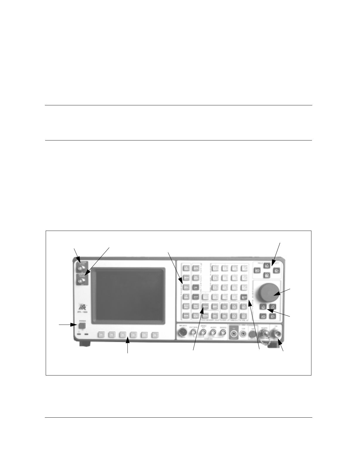
10-1
Wireless Solutions TDMA 1900 Macrocell Cell Site Maintenance Manual MTX08
10Appendix A:
IFR1900 setup
The IFR1900 is a versatile and powerful radio test instrument. Due to its
versatility and power, it has hundreds of optional settings and configurations.
Before beginning to use the IFR1900, the test technician should go through a
setup checklist to assure that those settings and configurations are correct for
testing cell site radios and RF equipment. This appendix provides a checklist
that, if followed, will assure that the IFR1900 can be used for testing the
radios and RF equipment at a TDMA 1900 Macrocell. Refer to Figure 10-1 as
you go through the checklist.
Figure 10-1
IFR 1900
Antenna
connector Duplexer
connector
Power
key
Soft keys Setup
key Enter
key T/R
connector
Data
entry
keys
Data
entry
knob
Field
select
keys
Mode
keys

10-2 Appendix A: IFR1900 setup
411-6201-500 Preliminary 03.03 July 1999
IFR setup checklist:
1. Connect ac power to the back of the IFR1900.
2. Press the POWER key a the lower left of the front of the IFR1900.
3. After the IFR logo screen appears, press the MTRS mode key.
4. Use the FIELD SELECT keys to move the cursor to item 2 -- Freq Error
Meter/Freq meter.
5. Press the ENTER key.
6. Press the SETUP key.
7. Use the FIELD SELECT keys, the ENTER key, and data entry keys to set
the setup options as follows:
Table 10-1
Setup options–Frequency Meter
8. Press the RET soft key.
9. Press the MTRS mode key.
10. Use the FIELD SELECT keys to move the cursor to item 3 -- Pwr Meter
(Pulse/CW).
11. Press the ENTER key.
12. Press the SETUP key.
13. Use the FIELD SELECT keys, the ENTER key, and data entry keys to set
the setup options as shown in Table 10-2.
Meter Range Autorange
Gate Time 1 second
Select Peak Hold Off
Upper Lmt Off
Set Upper Lmt 0.000 kHz
Lower Lmt Off
Set Lower Lmt 0.000 kHz
Set Alarm Off

Appendix A: IFR1900 setup 10-3
Wireless Solutions TDMA 1900 Macrocell Cell Site Maintenance Manual MTX08
Table 10-2
Setup options–Power Meter
14. Press the RET soft key.
15. Press the MTRS mode key.
16. Use the FIELD SELECT keys to select item 4 -- Dev Meter (Peak)
17. Press the ENTER key.
18. Press the SETUP key.
19. Use the FIELD SELECT keys, the ENTER key, and data entry keys to set
the setup options as shown in Table 10-3.
Table 10-3
Setup options–Deviation Meter
Meter Range Autorange
Measurement Type CW
dBm Enable On
Select Peak Hold Off
Upper Lmt Off
Set Upper Lmt 0.0 mW
Lower Lmt Off
Set Lower Lmt 0.0 mW
Set Alarm Off
Ext Loss/Gain 0.0 dB
Assumed RF Freq 4.8000 MHz
Meter Range Autorange
Select Peak Hold Off
Upper Lmt Off
Set Upper Lmt 0.00 kHz
Lower Lmt Off
Set Lower Lmt 0.00 kHz
Set Alarm Off
Average Off
Mode +/-Peak/2

10-4 Appendix A: IFR1900 setup
411-6201-500 Preliminary 03.03 July 1999
20. Press the RET soft key.
21. Press the MTRS mode key.
22. Use the FIELD SELECT keys to select item 7 -- SINAD Meter
23. Press the ENTER key.
24. Press the SETUP key.
25. Use the FIELD SELECT keys, the ENTER key, and data entry keys to set
the setup options as shown in Table 10-4.
Table 10-4
Setup options–SINAD Meter
26. Press the RET soft key.
27. Press the RET soft key.
28. Press the SCOPE/ANLZ mode key.
29. Press the SETUP key.
30. Use the FIELD SELECT keys to select item 4 -- Setup Analyzer.
31. Press the ENTER key.
32. If item 12, RF Mode is set to Channel, use the FIELD SELECT keys to
select item 12, then press the ENTER key until the mode is Direct.
33. Use the FIELD SELECT keys, the ENTER key, and data entry keys to set
the setup options as shown in Table 10-5.
Select SINAD In Demod Audio
Notch Filter Freq 1000 Hz
Select Peak Hold Off
Upper Limit Off
Set Upper Lmt 3.0dB
Lower Lmt Off
Set Lower Lmt 30.0 dB
Average On
Filter Select C Wt
Readout Res. .1 dB

Appendix A: IFR1900 setup 10-5
Wireless Solutions TDMA 1900 Macrocell Cell Site Maintenance Manual MTX08
Table 10-5
Setup options–Analyzer
34. Press the RET soft key.
35. Press the RCVR mode key.
36. Press the SETUP key.
37. Use the FIELD SELECT keys, the ENTER key, and data entry keys to set
the setup options as shown in Table 10-6.
38. Observe item 10-- Operation Mode. If it is set to anything other than
Direct, use the FIELD SELECT keys to select item 10, then use the
SELECT keys and the ENTER key to set the field to Direct.
Table 10-6
Setup options–Receiver Operational Mode
Scale dBm
Frequency 4.8000 MHz
Rcvr Input T/R
Input Atten 0 dB
Range 10 dB
Scan Width 20 kHz
Track Gen Off
Track Gen Lvl -90.0 dBm
Gen Lvl Units dBm
Velocity Factor 69.4 %
Mode Live
RF Mode Direct
Set Rcvr Freq 4.8000 MHz
Select Mod FM3
Select Rcvr In T/R
Select Input Atten 0 dB
Select AGC Type Auto
Rcvr Out Speaker Off
-sheet 1 of 2-

10-6 Appendix A: IFR1900 setup
411-6201-500 Preliminary 03.03 July 1999
39. Observe the status of RF lock (the field just above the F2 soft key). If it is
white, press the F2 key until it is pink.
40. Press the RET soft key.
41. Press the RF GEN mode key.
42. Observe the Forward/Reverse Field and the Frequency Band field in the
upper left area of the screen. The Forward/Reverse field should contain an
“R” and the frequency band field should contain an “HY”. If necessary,
use the FIELD SELECT keys, the data entry keys or knob, and the
ENTER key to set the two fields.
43. Press the SETUP key.
44. Use the FIELD SELECT keys to select item 5 -- RF Gen Output Setup.
45. Press the ENTER key
46. Observe item 3 -- RF Gen Format. If it is set to anything other than
CHANNEL, use the FIELD SELECT keys to select item 3, then use the
FIELD SELECT keys and the ENTER key to set the field to CHANNEL.
47. Use the FIELD SELECT keys, the ENTER key, and data entry keys to set
the setup options as shown in Table 10-7.
Table 10-7
Setup options–RF Generator Output
Rcvr Out Audio Out Off
Rcvr Out Demod Out Off
Auto Volume Level Off
Operation Mode Direct
Signaling Formats Digital
RF Gen Freq NNN NADC R
RF Gen Level -90.0 dBm
RF Gen Format Channel
RF Gen Level Units dBm
Source to Audio Out Off
Source to Demod Out Off
To Speaker None
-sheet 2 of 2-

Appendix A: IFR1900 setup 10-7
Wireless Solutions TDMA 1900 Macrocell Cell Site Maintenance Manual MTX08
Note: The NNN in the RF Gen Freq field represents the channel number
of the radio to be tested. Select any channel at this time. The actual
channel numbers will be set as the radio tests are performed.
48. Press the RET soft key.
49. Press the DPLX mode key.
50. Observe the channel fields (lines near the top of the screen that begin with
CH). They should read as follows:
CH NNN F HY CH NNN R HY
If this is not the way the lines read, use the FIELD SELECT keys and the
ENTER key to set them up as indicated. (NNN is a channel number. Use any
number for now. Actual channel numbers will be selected during the radio
tests.)
51. Use the FIELD SELECT keys to move the cursor to the word
TRANSMITTER at the top left of the screen.
52. Press the SETUP key.
53. Observe item 10 -- Operation Mode. If it is set to anything other than
“Channel”, use the FIELD SELECT keys to select item 10, then use the
ENTER key and the FIELD SELECT keys to set the field to “Channel”.
54. Use the FIELD SELECT keys, the ENTER key, and data entry keys to set
the setup options as shown in Table 10-8.
Table 10-8
Setup options–Transmitter Operational Mode
Set Rcvr Freq NNN NADC F
Select Mod FM3
Select Rcvr In T/R
Select Input Atten 0 dB
Select AGC Type Auto
Rcvr Out Speaker Off
Rcvr Out Audio Out Off
Rcvr Out Demod Out Off
Auto Volume Level Off
Operation Mode Channel
Signaling Formats Digital

10-8 Appendix A: IFR1900 setup
411-6201-500 Preliminary 03.03 July 1999
55. Press the RET soft key.
56. Use the FIELD SELECT keys to move the cursor to the word RECEIVER
at the top right of the screen.
57. Press the SETUP key.
58. Use the FIELD SELECT keys to select item 5 -- RF Gen Output Setup
59. Press the ENTER key.
60. Observe item 3 -- RF Gen Format. If it is set to anything other than
“Channel”, use the FIELD SELECT keys to select item 3, then use the
ENTER key and the FIELD SELECT keys to set the field to “Channel”.
61. Use the FIELD SELECT keys, the ENTER key, and data entry keys to set
the setup options as follows
Table 10-9
Setup options–RF Generator Output
62. Press the RET soft key.
The IFR1900 is now set up.
RF Gen Freq NNN NADC R
RF Gen Level -90.0 dBm
RF Gen Format Channel
RF Gen Level Units dBm
Source to Audio Out Off
Source to Demod Out Off
To Speaker None

11-1
Wireless Solutions TDMA 1900 Macrocell Cell Site Maintenance Manual MTX08
11Appendix B:
Channel and frequency tables
Channel numbering for 1900Mhz spectrum
Transmitter Channel Number Center Frequency (MHz)
Mobile 1 < N > 1999 0.030 N + 1849.980
Base 1 < N > 1999 0.030 N + 1930.020
PCS frequency sub-bands
Sub-band Bandwidth (MHz) Available channelsa
a. Channels 1 and 1999 are not used.
A 15 2 to 498
D 5 502 to 665
B 15 668 to 1165
E 5 1168 to 1332
F 5 1335 to 1498
C 15 1502 to 1998

11-2 Appendix B: Channel and frequency tables
411-6201-500 Preliminary 03.03 July 1999
Table 11-1
Frequency chart for TDMA 1900 Macrocell (channels 1–160)
Chan # Tx (MHz) Rx (MHz) Chan # Tx (MHz) Rx (MHz) Chan # Tx (MHz) Rx (MHz) Chan # Tx (MHz) Rx (MHz)
11930.05 1850.01 41 1931.25 1851.21 81 1932.45 1852.41 121 1933.65 1853.61
21930.08 1850.04 42 1931.28 1851.24 82 1932.48 1852.44 122 1933.68 1853.64
31930.11 1850.07 43 1931.31 1851.27 83 1932.51 1852.47 123 1933.71 1853.67
41930.14 1850.10 44 1931.34 1851.30 84 1932.54 1852.50 124 1933.74 1853.70
51930.17 1850.13 45 1931.37 1851.33 85 1932.57 1852.53 125 1933.77 1853.73
61930.20 1850.16 46 1931.40 1851.36 86 1932.60 1852.56 126 1933.80 1853.76
71930.23 1850.19 47 1931.43 1851.39 87 1932.63 1852.59 127 1933.83 1853.79
81930.26 1850.22 48 1931.46 1851.42 88 1932.66 1852.62 128 1933.86 1853.82
91930.29 1850.25 49 1931.49 1851.45 89 1932.69 1852.65 129 1933.89 1853.85
10 1930.32 1850.28 50 1931.52 1851.48 90 1932.72 1852.68 130 1933.92 1853.88
11 1930.35 1850.31 51 1931.55 1851.51 91 1932.75 1852.71 131 1933.95 1853.91
12 1930.38 1850.34 52 1931.58 1851.54 92 1932.78 1852.74 132 1933.98 1853.94
13 1930.41 1850.37 53 1931.61 1851.57 93 1932.81 1852.77 133 1934.01 1853.97
14 1930.44 1850.40 54 1931.64 1851.60 94 1932.84 1852.80 134 1934.04 1854.00
15 1930.47 1850.43 55 1931.67 1851.63 95 1932.87 1852.83 135 1934.07 1854.03
16 1930.50 1850.46 56 1931.70 1851.66 96 1932.90 1852.86 136 1934.10 1854.06
17 1930.53 1850.49 57 1931.73 1851.69 97 1932.93 1852.89 137 1934.13 1854.09
18 1930.56 1850.52 58 1931.76 1851.72 98 1932.96 1852.92 138 1934.16 1854.12
19 1930.59 1850.55 59 1931.79 1851.75 99 1932.99 1852.95 139 1934.19 1854.15
20 1930.62 1850.58 60 1931.82 1851.78 100 1933.02 1852.98 140 1934.22 1854.18
21 1930.65 1850.61 61 1931.85 1851.81 101 1933.05 1853.01 141 1934.25 1854.21
22 1930.68 1850.64 62 1931.88 1851.84 102 1933.08 1853.04 142 1934.28 1854.24
23 1930.71 1850.67 63 1931.91 1851.87 103 1933.11 1853.07 143 1934.31 1854.27
24 1930.74 1850.70 64 1931.94 1851.90 104 1933.14 1853.10 144 1934.34 1854.30
25 1930.77 1850.73 65 1931.97 1851.93 105 1933.17 1853.13 145 1934.37 1854.33
26 1930.80 1850.76 66 1932.00 1851.96 106 1933.20 1853.16 146 1934.40 1854.36
27 1930.83 1850.79 67 1932.03 1851.99 107 1933.23 1853.19 147 1934.43 1854.39
28 1930.86 1850.82 68 1932.06 1852.02 108 1933.26 1853.22 148 1934.46 1854.42
29 1930.89 1850.85 69 1932.09 1852.05 109 1933.29 1853.25 149 1934.49 1854.45
30 1930.92 1850.88 70 1932.12 1852.08 110 1933.32 1853.28 150 1934.52 1854.48
31 1930.95 1850.91 71 1932.15 1852.11 111 1933.35 1853.31 151 1934.55 1854.51
32 1930.98 1850.94 72 1932.18 1852.14 112 1933.38 1853.34 152 1934.58 1854.54
33 1931.01 1850.97 73 1932.21 1852.17 113 1933.41 1853.37 153 1934.61 1854.57
34 1931.04 1851.00 74 1932.24 1852.20 114 1933.44 1853.40 154 1934.64 1854.60
35 1931.07 1851.03 75 1932.27 1852.23 115 1933.47 1853.43 155 1934.67 1854.63
36 1931.10 1851.06 76 1932.30 1852.26 116 1933.50 1853.46 156 1934.70 1854.66
37 1931.13 1851.09 77 1932.33 1852.29 117 1933.53 1853.49 157 1934.73 1854.69
38 1931.16 1851.12 78 1932.36 1852.32 118 1933.56 1853.52 158 1934.76 1854.72
39 1931.19 1851.15 79 1932.39 1852.35 119 1933.59 1853.55 159 1934.79 1854.75
40 1931.22 1851.18 80 1932.42 1852.38 120 1933.62 1853.58 160 1934.82 1854.78

Appendix B: Channel and frequency tables 11-3
Wireless Solutions TDMA 1900 Macrocell Cell Site Maintenance Manual MTX08
Table 11-2
Frequency chart for TDMA 1900 Macrocell (channels 161–320)
161 1934.85 1854.81 201 1936.05 1856.01 241 1937.25 1857.21 281 1938.45 1858.41
162 1934.88 1854.84 202 1936.08 1856.04 242 1937.28 1857.24 282 1938.48 1858.44
163 1934.91 1854.87 203 1936.11 1856.07 243 1937.31 1857.27 283 1938.51 1858.47
164 1934.94 1854.90 204 1936.14 1856.10 244 1937.34 1857.30 284 1938.54 1858.50
165 1934.97 1854.93 205 1936.17 1856.13 245 1937.37 1857.33 285 1938.57 1858.53
166 1935.00 1854.96 206 1936.20 1856.16 246 1937.40 1857.36 286 1938.60 1858.56
167 1935.03 1854.99 207 1936.23 1856.19 247 1937.43 1857.39 287 1938.63 1858.59
168 1935.06 1855.02 208 1936.26 1856.22 248 1937.46 1857.42 288 1938.66 1858.62
169 1935.09 1855.05 209 1936.29 1856.25 249 1937.49 1857.45 289 1938.69 1858.65
170 1935.12 1855.08 210 1936.32 1856.28 250 1937.52 1857.48 290 1938.72 1858.68
171 1935.15 1855.11 211 1936.35 1856.31 251 1937.55 1857.51 291 1938.75 1858.71
172 1935.18 1855.14 212 1936.38 1856.34 252 1937.58 1857.54 292 1938.78 1858.74
173 1935.21 1855.17 213 1936.41 1856.37 253 1937.61 1857.57 293 1938.81 1858.77
174 1935.24 1855.20 214 1936.44 1856.40 254 1937.64 1857.60 294 1938.84 1858.80
175 1935.27 1855.23 215 1936.47 1856.43 255 1937.67 1857.63 295 1938.87 1858.83
176 1935.30 1855.26 216 1936.50 1856.46 256 1937.70 1857.66 296 1938.90 1858.86
177 1935.33 1855.29 217 1936.53 1856.49 257 1937.73 1857.69 297 1938.93 1858.89
178 1935.36 1855.32 218 1936.56 1856.52 258 1937.76 1857.72 298 1938.96 1858.92
179 1935.39 1855.35 219 1936.59 1856.55 259 1937.79 1857.75 299 1938.99 1858.95
180 1935.42 1855.38 220 1936.62 1856.58 260 1937.82 1857.78 300 1939.02 1858.98
181 1935.45 1855.41 221 1936.65 1856.61 261 1937.85 1857.81 301 1939.05 1859.01
182 1935.48 1855.44 222 1936.68 1856.64 262 1937.88 1857.84 302 1939.08 1859.04
183 1935.51 1855.47 223 1936.71 1856.67 263 1937.91 1857.87 303 1939.11 1859.07
184 1935.54 1855.50 224 1936.74 1856.70 264 1937.94 1857.90 304 1939.14 1859.10
185 1935.57 1855.53 225 1936.77 1856.73 265 1937.97 1857.93 305 1939.17 1859.13
186 1935.60 1855.56 226 1936.80 1856.76 266 1938.00 1857.96 306 1939.20 1859.16
187 1935.63 1855.59 227 1936.83 1856.79 267 1938.03 1857.99 307 1939.23 1859.19
188 1935.66 1855.62 228 1936.86 1856.82 268 1938.06 1858.02 308 1939.26 1859.22
189 1935.69 1855.65 229 1936.89 1856.85 269 1938.09 1858.05 309 1939.29 1859.25
190 1935.72 1855.68 230 1936.92 1856.88 270 1938.12 1858.08 310 1939.32 1859.28
191 1935.75 1855.71 231 1936.95 1856.91 271 1938.15 1858.11 311 1939.35 1859.31
192 1935.78 1855.74 232 1936.98 1856.94 272 1938.18 1858.14 312 1939.38 1859.34
193 1935.81 1855.77 233 1937.01 1856.97 273 1938.21 1858.17 313 1939.41 1859.37
194 1935.84 1855.80 234 1937.04 1857.00 274 1938.24 1858.20 314 1939.44 1859.40
195 1935.87 1855.83 235 1937.07 1857.03 275 1938.27 1858.23 315 1939.47 1859.43
196 1935.90 1855.86 236 1937.10 1857.06 276 1938.30 1858.26 316 1939.50 1859.46
197 1935.93 1855.89 237 1937.13 1857.09 277 1938.33 1858.29 317 1939.53 1859.49
198 1935.96 1855.92 238 1937.16 1857.12 278 1938.36 1858.32 318 1939.56 1859.52
199 1935.99 1855.95 239 1937.19 1857.15 279 1938.39 1858.35 319 1939.59 1859.55
200 1936.02 1855.98 240 1937.22 1857.18 280 1938.42 1858.38 320 1939.62 1859.58

11-4 Appendix B: Channel and frequency tables
411-6201-500 Preliminary 03.03 July 1999
Table 11-3
Frequency chart for TDMA 1900 Macrocell (channels 321–480)
321 1939.65 1859.61 361 1940.85 1860.81 401 1942.05 1862.01 441 1943.25 1863.21
322 1939.68 1859.64 362 1940.88 1860.84 402 1942.08 1862.04 442 1943.28 1863.24
323 1939.71 1859.67 363 1940.91 1860.87 403 1942.11 1862.07 443 1943.31 1863.27
324 1939.74 1859.70 364 1940.94 1860.90 404 1942.14 1862.10 444 1943.34 1863.30
325 1939.77 1859.73 365 1940.97 1860.93 405 1942.17 1862.13 445 1943.37 1863.33
326 1939.80 1859.76 366 1941.00 1860.96 406 1942.20 1862.16 446 1943.40 1863.36
327 1939.83 1859.79 367 1941.03 1860.99 407 1942.23 1862.19 447 1943.43 1863.39
328 1939.86 1859.82 368 1941.06 1861.02 408 1942.26 1862.22 448 1943.46 1863.42
329 1939.89 1859.85 369 1941.09 1861.05 409 1942.29 1862.25 449 1943.49 1863.45
330 1939.92 1859.88 370 1941.12 1861.08 410 1942.32 1862.28 450 1943.52 1863.48
331 1939.95 1859.91 371 1941.15 1861.11 411 1942.35 1862.31 451 1943.55 1863.51
332 1939.98 1859.94 372 1941.18 1861.14 412 1942.38 1862.34 452 1943.58 1863.54
333 1940.01 1859.97 373 1941.21 1861.17 413 1942.41 1862.37 453 1943.61 1863.57
334 1940.04 1860.00 374 1941.24 1861.20 414 1942.44 1862.40 454 1943.64 1863.60
335 1940.07 1860.03 375 1941.27 1861.23 415 1942.47 1862.43 455 1943.67 1863.63
336 1940.10 1860.06 376 1941.30 1861.26 416 1942.50 1862.46 456 1943.70 1863.66
337 1940.13 1860.09 377 1941.33 1861.29 417 1942.53 1862.49 457 1943.73 1863.69
338 1940.16 1860.12 378 1941.36 1861.32 418 1942.56 1862.52 458 1943.76 1863.72
339 1940.19 1860.15 379 1941.39 1861.35 419 1942.59 1862.55 459 1943.79 1863.75
340 1940.22 1860.18 380 1941.42 1861.38 420 1942.62 1862.58 460 1943.82 1863.78
341 1940.25 1860.21 381 1941.45 1861.41 421 1942.65 1862.61 461 1943.85 1863.81
342 1940.28 1860.24 382 1941.48 1861.44 422 1942.68 1862.64 462 1943.88 1863.84
343 1940.31 1860.27 383 1941.51 1861.47 423 1942.71 1862.67 463 1943.91 1863.87
344 1940.34 1860.30 384 1941.54 1861.50 424 1942.74 1862.70 464 1943.94 1863.90
345 1940.37 1860.33 385 1941.57 1861.53 425 1942.77 1862.73 465 1943.97 1863.93
346 1940.40 1860.36 386 1941.60 1861.56 426 1942.80 1862.76 466 1944.00 1863.96
347 1940.43 1860.39 387 1941.63 1861.59 427 1942.83 1862.79 467 1944.03 1863.99
348 1940.46 1860.42 388 1941.66 1861.62 428 1942.86 1862.82 468 1944.06 1864.02
349 1940.49 1860.45 389 1941.69 1861.65 429 1942.89 1862.85 469 1944.09 1864.05
350 1940.52 1860.48 390 1941.72 1861.68 430 1942.92 1862.88 470 1944.12 1864.08
351 1940.55 1860.51 391 1941.75 1861.71 431 1942.95 1862.91 471 1944.15 1864.11
352 1940.58 1860.54 392 1941.78 1861.74 432 1942.98 1862.94 472 1944.18 1864.14
353 1940.61 1860.57 393 1941.81 1861.77 433 1943.01 1862.97 473 1944.21 1864.17
354 1940.64 1860.60 394 1941.84 1861.80 434 1943.04 1863.00 474 1944.24 1864.20
355 1940.67 1860.63 395 1941.87 1861.83 435 1943.07 1863.03 475 1944.27 1864.23
356 1940.70 1860.66 396 1941.90 1861.86 436 1943.10 1863.06 476 1944.30 1864.26
357 1940.73 1860.69 397 1941.93 1861.89 437 1943.13 1863.09 477 1944.33 1864.29
358 1940.76 1860.72 398 1941.96 1861.92 438 1943.16 1863.12 478 1944.36 1864.32
359 1940.79 1860.75 399 1941.99 1861.95 439 1943.19 1863.15 479 1944.39 1864.35
360 1940.82 1860.78 400 1942.02 1861.98 440 1943.22 1863.18 480 1944.42 1864.38

Appendix B: Channel and frequency tables 11-5
Wireless Solutions TDMA 1900 Macrocell Cell Site Maintenance Manual MTX08
Table 11-4
Frequency chart for TDMA 1900 Macrocell (channels 481–640)
481 1944.45 1864.41 521 1945.65 1865.61 561 1946.85 1866.81 601 1948.05 1868.01
482 1944.48 1864.44 522 1945.68 1865.64 562 1946.88 1866.84 602 1948.08 1868.04
483 1944.51 1864.47 523 1945.71 1865.67 563 1946.91 1866.87 603 1948.11 1868.07
484 1944.54 1864.50 524 1945.74 1865.70 564 1946.94 1866.90 604 1948.14 1868.10
485 1944.57 1864.53 525 1945.77 1865.73 565 1946.97 1866.93 605 1948.17 1868.13
486 1944.60 1864.56 526 1945.80 1865.76 566 1947.00 1866.96 606 1948.20 1868.16
487 1944.63 1864.59 527 1945.83 1865.79 567 1947.03 1866.99 607 1948.23 1868.19
488 1944.66 1864.62 528 1945.86 1865.82 568 1947.06 1867.02 608 1948.26 1868.22
489 1944.69 1864.65 529 1945.89 1865.85 569 1947.09 1867.05 609 1948.29 1868.25
490 1944.72 1864.68 530 1945.92 1865.88 570 1947.12 1867.08 610 1948.32 1868.28
491 1944.75 1864.71 531 1945.95 1865.91 571 1947.15 1867.11 611 1948.35 1868.31
492 1944.78 1864.74 532 1945.98 1865.94 572 1947.18 1867.14 612 1948.38 1868.34
493 1944.81 1864.77 533 1946.01 1865.97 573 1947.21 1867.17 613 1948.41 1868.37
494 1944.84 1864.80 534 1946.04 1866.00 574 1947.24 1867.20 614 1948.44 1868.40
495 1944.87 1864.83 535 1946.07 1866.03 575 1947.27 1867.23 615 1948.47 1868.43
496 1944.90 1864.86 536 1946.10 1866.06 576 1947.30 1867.26 616 1948.50 1868.46
497 1944.93 1864.89 537 1946.13 1866.09 577 1947.33 1867.29 617 1948.53 1868.49
498 1944.96 1864.92 538 1946.16 1866.12 578 1947.36 1867.32 618 1948.56 1868.52
499 1944.99 1864.95 539 1946.19 1866.15 579 1947.39 1867.35 619 1948.59 1868.55
500 1945.02 1864.98 540 1946.22 1866.18 580 1947.42 1867.38 620 1948.62 1868.58
501 1945.05 1865.01 541 1946.25 1866.21 581 1947.45 1867.41 621 1948.65 1868.61
502 1945.08 1865.04 542 1946.28 1866.24 582 1947.48 1867.44 622 1948.68 1868.64
503 1945.11 1865.07 543 1946.31 1866.27 583 1947.51 1867.47 623 1948.71 1868.67
504 1945.14 1865.10 544 1946.34 1866.30 584 1947.54 1867.50 624 1948.74 1868.70
505 1945.17 1865.13 545 1946.37 1866.33 585 1947.57 1867.53 625 1948.77 1868.73
506 1945.20 1865.16 546 1946.40 1866.36 586 1947.60 1867.56 626 1948.80 1868.76
507 1945.23 1865.19 547 1946.43 1866.39 587 1947.63 1867.59 627 1948.83 1868.79
508 1945.26 1865.22 548 1946.46 1866.42 588 1947.66 1867.62 628 1948.86 1868.82
509 1945.29 1865.25 549 1946.49 1866.45 589 1947.69 1867.65 629 1948.89 1868.85
510 1945.32 1865.28 550 1946.52 1866.48 590 1947.72 1867.68 630 1948.92 1868.88
511 1945.35 1865.31 551 1946.55 1866.51 591 1947.75 1867.71 631 1948.95 1868.91
512 1945.38 1865.34 552 1946.58 1866.54 592 1947.78 1867.74 632 1948.98 1868.94
513 1945.41 1865.37 553 1946.61 1866.57 593 1947.81 1867.77 633 1949.01 1868.97
514 1945.44 1865.40 554 1946.64 1866.60 594 1947.84 1867.80 634 1949.04 1869.00
515 1945.47 1865.43 555 1946.67 1866.63 595 1947.87 1867.83 635 1949.07 1869.03
516 1945.50 1865.46 556 1946.70 1866.66 596 1947.90 1867.86 636 1949.10 1869.06
517 1945.53 1865.49 557 1946.73 1866.69 597 1947.93 1867.89 637 1949.13 1869.09
518 1945.56 1865.52 558 1946.76 1866.72 598 1947.96 1867.92 638 1949.16 1869.12
519 1945.59 1865.55 559 1946.79 1866.75 599 1947.99 1867.95 639 1949.19 1869.15
520 1945.62 1865.58 560 1946.82 1866.78 600 1948.02 1867.98 640 1949.22 1869.18

11-6 Appendix B: Channel and frequency tables
411-6201-500 Preliminary 03.03 July 1999
Table 11-5
Frequency chart for TDMA 1900 Macrocell (channels 641–800)
641 1949.25 1869.21 681 1950.45 1870.41 721 1951.65 1871.61 761 1952.85 1872.81
642 1949.28 1869.24 682 1950.48 1870.44 722 1951.68 1871.64 762 1952.88 1872.84
643 1949.31 1869.27 683 1950.51 1870.47 723 1951.71 1871.67 763 1952.91 1872.87
644 1949.34 1869.30 684 1950.54 1870.50 724 1951.74 1871.70 764 1952.94 1872.90
645 1949.37 1869.33 685 1950.57 1870.53 725 1951.77 1871.73 765 1952.97 1872.93
646 1949.40 1869.36 686 1950.60 1870.56 726 1951.80 1871.76 766 1953.00 1872.96
647 1949.43 1869.39 687 1950.63 1870.59 727 1951.83 1871.79 767 1953.03 1872.99
648 1949.46 1869.42 688 1950.66 1870.62 728 1951.86 1871.82 768 1953.06 1873.02
649 1949.49 1869.45 689 1950.69 1870.65 729 1951.89 1871.85 769 1953.09 1873.05
650 1949.52 1869.48 690 1950.72 1870.68 730 1951.92 1871.88 770 1953.12 1873.08
651 1949.55 1869.51 691 1950.75 1870.71 731 1951.95 1871.91 771 1953.15 1873.11
652 1949.58 1869.54 692 1950.78 1870.74 732 1951.98 1871.94 772 1953.18 1873.14
653 1949.61 1869.57 693 1950.81 1870.77 733 1952.01 1871.97 773 1953.21 1873.17
654 1949.64 1869.60 694 1950.84 1870.80 734 1952.04 1872.00 774 1953.24 1873.20
655 1949.67 1869.63 695 1950.87 1870.83 735 1952.07 1872.03 775 1953.27 1873.23
656 1949.70 1869.66 696 1950.90 1870.86 736 1952.10 1872.06 776 1953.30 1873.26
657 1949.73 1869.69 697 1950.93 1870.89 737 1952.13 1872.09 777 1953.33 1873.29
658 1949.76 1869.72 698 1950.96 1870.92 738 1952.16 1872.12 778 1953.36 1873.32
659 1949.79 1869.75 699 1950.99 1870.95 739 1952.19 1872.15 779 1953.39 1873.35
660 1949.82 1869.78 700 1951.02 1870.98 740 1952.22 1872.18 780 1953.42 1873.38
661 1949.85 1869.81 701 1951.05 1871.01 741 1952.25 1872.21 781 1953.45 1873.41
662 1949.88 1869.84 702 1951.08 1871.04 742 1952.28 1872.24 782 1953.48 1873.44
663 1949.91 1869.87 703 1951.11 1871.07 743 1952.31 1872.27 783 1953.51 1873.47
664 1949.94 1869.90 704 1951.14 1871.10 744 1952.34 1872.30 784 1953.54 1873.50
665 1949.97 1869.93 705 1951.17 1871.13 745 1952.37 1872.33 785 1953.57 1873.53
666 1950.00 1869.96 706 1951.20 1871.16 746 1952.40 1872.36 786 1953.60 1873.56
667 1950.03 1869.99 707 1951.23 1871.19 747 1952.43 1872.39 787 1953.63 1873.59
668 1950.06 1870.02 708 1951.26 1871.22 748 1952.46 1872.42 788 1953.66 1873.62
669 1950.09 1870.05 709 1951.29 1871.25 749 1952.49 1872.45 789 1953.69 1873.65
670 1950.12 1870.08 710 1951.32 1871.28 750 1952.52 1872.48 790 1953.72 1873.68
671 1950.15 1870.11 711 1951.35 1871.31 751 1952.55 1872.51 791 1953.75 1873.71
672 1950.18 1870.14 712 1951.38 1871.34 752 1952.58 1872.54 792 1953.78 1873.74
673 1950.21 1870.17 713 1951.41 1871.37 753 1952.61 1872.57 793 1953.81 1873.77
674 1950.24 1870.20 714 1951.44 1871.40 754 1952.64 1872.60 794 1953.84 1873.80
675 1950.27 1870.23 715 1951.47 1871.43 755 1952.67 1872.63 795 1953.87 1873.83
676 1950.30 1870.26 716 1951.50 1871.46 756 1952.70 1872.66 796 1953.90 1873.86
677 1950.33 1870.29 717 1951.53 1871.49 757 1952.73 1872.69 797 1953.93 1873.89
678 1950.36 1870.32 718 1951.56 1871.52 758 1952.76 1872.72 798 1953.96 1873.92
679 1950.39 1870.35 719 1951.59 1871.55 759 1952.79 1872.75 799 1953.99 1873.95
680 1950.42 1870.38 720 1951.62 1871.58 760 1952.82 1872.78 800 1954.02 1873.98

Appendix B: Channel and frequency tables 11-7
Wireless Solutions TDMA 1900 Macrocell Cell Site Maintenance Manual MTX08
Table 11-6
Frequency chart for TDMA 1900 Macrocell (channels 801–960)
801 1954.05 1874.01 841 1955.25 1875.21 881 1956.45 1876.41 921 1957.65 1877.61
802 1954.08 1874.04 842 1955.28 1875.24 882 1956.48 1876.44 922 1957.68 1877.64
803 1954.11 1874.07 843 1955.31 1875.27 883 1956.51 1876.47 923 1957.71 1877.67
804 1954.14 1874.10 844 1955.34 1875.30 884 1956.54 1876.50 924 1957.74 1877.70
805 1954.17 1874.13 845 1955.37 1875.33 885 1956.57 1876.53 925 1957.77 1877.73
806 1954.20 1874.16 846 1955.40 1875.36 886 1956.60 1876.56 926 1957.80 1877.76
807 1954.23 1874.19 847 1955.43 1875.39 887 1956.63 1876.59 927 1957.83 1877.79
808 1954.26 1874.22 848 1955.46 1875.42 888 1956.66 1876.62 928 1957.86 1877.82
809 1954.29 1874.25 849 1955.49 1875.45 889 1956.69 1876.65 929 1957.89 1877.85
810 1954.32 1874.28 850 1955.52 1875.48 890 1956.72 1876.68 930 1957.92 1877.88
811 1954.35 1874.31 851 1955.55 1875.51 891 1956.75 1876.71 931 1957.95 1877.91
812 1954.38 1874.34 852 1955.58 1875.54 892 1956.78 1876.74 932 1957.98 1877.94
813 1954.41 1874.37 853 1955.61 1875.57 893 1956.81 1876.77 933 1958.01 1877.97
814 1954.44 1874.40 854 1955.64 1875.60 894 1956.84 1876.80 934 1958.04 1878.00
815 1954.47 1874.43 855 1955.67 1875.63 895 1956.87 1876.83 935 1958.07 1878.03
816 1954.50 1874.46 856 1955.70 1875.66 896 1956.90 1876.86 936 1958.10 1878.06
817 1954.53 1874.49 857 1955.73 1875.69 897 1956.93 1876.89 937 1958.13 1878.09
818 1954.56 1874.52 858 1955.76 1875.72 898 1956.96 1876.92 938 1958.16 1878.12
819 1954.59 1874.55 859 1955.79 1875.75 899 1956.99 1876.95 939 1958.19 1878.15
820 1954.62 1874.58 860 1955.82 1875.78 900 1957.02 1876.98 940 1958.22 1878.18
821 1954.65 1874.61 861 1955.85 1875.81 901 1957.05 1877.01 941 1958.25 1878.21
822 1954.68 1874.64 862 1955.88 1875.84 902 1957.08 1877.04 942 1958.28 1878.24
823 1954.71 1874.67 863 1955.91 1875.87 903 1957.11 1877.07 943 1958.31 1878.27
824 1954.74 1874.70 864 1955.94 1875.90 904 1957.14 1877.10 944 1958.34 1878.30
825 1954.77 1874.73 865 1955.97 1875.93 905 1957.17 1877.13 945 1958.37 1878.33
826 1954.80 1874.76 866 1956.00 1875.96 906 1957.20 1877.16 946 1958.40 1878.36
827 1954.83 1874.79 867 1956.03 1875.99 907 1957.23 1877.19 947 1958.43 1878.39
828 1954.86 1874.82 868 1956.06 1876.02 908 1957.26 1877.22 948 1958.46 1878.42
829 1954.89 1874.85 869 1956.09 1876.05 909 1957.29 1877.25 949 1958.49 1878.45
830 1954.92 1874.88 870 1956.12 1876.08 910 1957.32 1877.28 950 1958.52 1878.48
831 1954.95 1874.91 871 1956.15 1876.11 911 1957.35 1877.31 951 1958.55 1878.51
832 1954.98 1874.94 872 1956.18 1876.14 912 1957.38 1877.34 952 1958.58 1878.54
833 1955.01 1874.97 873 1956.21 1876.17 913 1957.41 1877.37 953 1958.61 1878.57
834 1955.04 1875.00 874 1956.24 1876.20 914 1957.44 1877.40 954 1958.64 1878.60
835 1955.07 1875.03 875 1956.27 1876.23 915 1957.47 1877.43 955 1958.67 1878.63
836 1955.10 1875.06 876 1956.30 1876.26 916 1957.50 1877.46 956 1958.70 1878.66
837 1955.13 1875.09 877 1956.33 1876.29 917 1957.53 1877.49 957 1958.73 1878.69
838 1955.16 1875.12 878 1956.36 1876.32 918 1957.56 1877.52 958 1958.76 1878.72
839 1955.19 1875.15 879 1956.39 1876.35 919 1957.59 1877.55 959 1958.79 1878.75
840 1955.22 1875.18 880 1956.42 1876.38 920 1957.62 1877.58 960 1958.82 1878.78

11-8 Appendix B: Channel and frequency tables
411-6201-500 Preliminary 03.03 July 1999
Table 11-7
Frequency chart for TDMA 1900 Macrocell (channels 961–1120)
961 1958.85 1878.81 1001 1960.05 1880.01 1041 1961.25 1881.21 1081 1962.45 1882.41
962 1958.88 1878.84 1002 1960.08 1880.04 1042 1961.28 1881.24 1082 1962.48 1882.44
963 1958.91 1878.87 1003 1960.11 1880.07 1043 1961.31 1881.27 1083 1962.51 1882.47
964 1958.94 1878.90 1004 1960.14 1880.10 1044 1961.34 1881.30 1084 1962.54 1882.50
965 1958.97 1878.93 1005 1960.17 1880.13 1045 1961.37 1881.33 1085 1962.57 1882.53
966 1959.00 1878.96 1006 1960.20 1880.16 1046 1961.40 1881.36 1086 1962.60 1882.56
967 1959.03 1878.99 1007 1960.23 1880.19 1047 1961.43 1881.39 1087 1962.63 1882.59
968 1959.06 1879.02 1008 1960.26 1880.22 1048 1961.46 1881.42 1088 1962.66 1882.62
969 1959.09 1879.05 1009 1960.29 1880.25 1049 1961.49 1881.45 1089 1962.69 1882.65
970 1959.12 1879.08 1010 1960.32 1880.28 1050 1961.52 1881.48 1090 1962.72 1882.68
971 1959.15 1879.11 1011 1960.35 1880.31 1051 1961.55 1881.51 1091 1962.75 1882.71
972 1959.18 1879.14 1012 1960.38 1880.34 1052 1961.58 1881.54 1092 1962.78 1882.74
973 1959.21 1879.17 1013 1960.41 1880.37 1053 1961.61 1881.57 1093 1962.81 1882.77
974 1959.24 1879.20 1014 1960.44 1880.40 1054 1961.64 1881.60 1094 1962.84 1882.80
975 1959.27 1879.23 1015 1960.47 1880.43 1055 1961.67 1881.63 1095 1962.87 1882.83
976 1959.30 1879.26 1016 1960.50 1880.46 1056 1961.70 1881.66 1096 1962.90 1882.86
977 1959.33 1879.29 1017 1960.53 1880.49 1057 1961.73 1881.69 1097 1962.93 1882.89
978 1959.36 1879.32 1018 1960.56 1880.52 1058 1961.76 1881.72 1098 1962.96 1882.92
979 1959.39 1879.35 1019 1960.59 1880.55 1059 1961.79 1881.75 1099 1962.99 1882.95
980 1959.42 1879.38 1020 1960.62 1880.58 1060 1961.82 1881.78 1100 1963.02 1882.98
981 1959.45 1879.41 1021 1960.65 1880.61 1061 1961.85 1881.81 1101 1963.05 1883.01
982 1959.48 1879.44 1022 1960.68 1880.64 1062 1961.88 1881.84 1102 1963.08 1883.04
983 1959.51 1879.47 1023 1960.71 1880.67 1063 1961.91 1881.87 1103 1963.11 1883.07
984 1959.54 1879.50 1024 1960.74 1880.70 1064 1961.94 1881.90 1104 1963.14 1883.10
985 1959.57 1879.53 1025 1960.77 1880.73 1065 1961.97 1881.93 1105 1963.17 1883.13
986 1959.60 1879.56 1026 1960.80 1880.76 1066 1962.00 1881.96 1106 1963.20 1883.16
987 1959.63 1879.59 1027 1960.83 1880.79 1067 1962.03 1881.99 1107 1963.23 1883.19
988 1959.66 1879.62 1028 1960.86 1880.82 1068 1962.06 1882.02 1108 1963.26 1883.22
989 1959.69 1879.65 1029 1960.89 1880.85 1069 1962.09 1882.05 1109 1963.29 1883.25
990 1959.72 1879.68 1030 1960.92 1880.88 1070 1962.12 1882.08 1110 1963.32 1883.28
991 1959.75 1879.71 1031 1960.95 1880.91 1071 1962.15 1882.11 1111 1963.35 1883.31
992 1959.78 1879.74 1032 1960.98 1880.94 1072 1962.18 1882.14 1112 1963.38 1883.34
993 1959.81 1879.77 1033 1961.01 1880.97 1073 1962.21 1882.17 1113 1963.41 1883.37
994 1959.84 1879.80 1034 1961.04 1881.00 1074 1962.24 1882.20 1114 1963.44 1883.40
995 1959.87 1879.83 1035 1961.07 1881.03 1075 1962.27 1882.23 1115 1963.47 1883.43
996 1959.90 1879.86 1036 1961.10 1881.06 1076 1962.30 1882.26 1116 1963.50 1883.46
997 1959.93 1879.89 1037 1961.13 1881.09 1077 1962.33 1882.29 1117 1963.53 1883.49
998 1959.96 1879.92 1038 1961.16 1881.12 1078 1962.36 1882.32 1118 1963.56 1883.52
999 1959.99 1879.95 1039 1961.19 1881.15 1079 1962.39 1882.35 1119 1963.59 1883.55
1000 1960.02 1879.98 1040 1961.22 1881.18 1080 1962.42 1882.38 1120 1963.62 1883.58

Appendix B: Channel and frequency tables 11-9
Wireless Solutions TDMA 1900 Macrocell Cell Site Maintenance Manual MTX08
Table 11-8
Frequency chart for TDMA 1900 Macrocell (channels 1121–1280)
1121 1963.65 1883.61 1161 1964.85 1884.81 1201 1966.05 1886.01 1241 1967.25 1887.21
1122 1963.68 1883.64 1162 1964.88 1884.84 1202 1966.08 1886.04 1242 1967.28 1887.24
1123 1963.71 1883.67 1163 1964.91 1884.87 1203 1966.11 1886.07 1243 1967.31 1887.27
1124 1963.74 1883.70 1164 1964.94 1884.90 1204 1966.14 1886.10 1244 1967.34 1887.30
1125 1963.77 1883.73 1165 1964.97 1884.93 1205 1966.17 1886.13 1245 1967.37 1887.33
1126 1963.80 1883.76 1166 1965.00 1884.96 1206 1966.20 1886.16 1246 1967.40 1887.36
1127 1963.83 1883.79 1167 1965.03 1884.99 1207 1966.23 1886.19 1247 1967.43 1887.39
1128 1963.86 1883.82 1168 1965.06 1885.02 1208 1966.26 1886.22 1248 1967.46 1887.42
1129 1963.89 1883.85 1169 1965.09 1885.05 1209 1966.29 1886.25 1249 1967.49 1887.45
1130 1963.92 1883.88 1170 1965.12 1885.08 1210 1966.32 1886.28 1250 1967.52 1887.48
1131 1963.95 1883.91 1171 1965.15 1885.11 1211 1966.35 1886.31 1251 1967.55 1887.51
1132 1963.98 1883.94 1172 1965.18 1885.14 1212 1966.38 1886.34 1252 1967.58 1887.54
1133 1964.01 1883.97 1173 1965.21 1885.17 1213 1966.41 1886.37 1253 1967.61 1887.57
1134 1964.04 1884.00 1174 1965.24 1885.20 1214 1966.44 1886.40 1254 1967.64 1887.60
1135 1964.07 1884.03 1175 1965.27 1885.23 1215 1966.47 1886.43 1255 1967.67 1887.63
1136 1964.10 1884.06 1176 1965.30 1885.26 1216 1966.50 1886.46 1256 1967.70 1887.66
1137 1964.13 1884.09 1177 1965.33 1885.29 1217 1966.53 1886.49 1257 1967.73 1887.69
1138 1964.16 1884.12 1178 1965.36 1885.32 1218 1966.56 1886.52 1258 1967.76 1887.72
1139 1964.19 1884.15 1179 1965.39 1885.35 1219 1966.59 1886.55 1259 1967.79 1887.75
1140 1964.22 1884.18 1180 1965.42 1885.38 1220 1966.62 1886.58 1260 1967.82 1887.78
1141 1964.25 1884.21 1181 1965.45 1885.41 1221 1966.65 1886.61 1261 1967.85 1887.81
1142 1964.28 1884.24 1182 1965.48 1885.44 1222 1966.68 1886.64 1262 1967.88 1887.84
1143 1964.31 1884.27 1183 1965.51 1885.47 1223 1966.71 1886.67 1263 1967.91 1887.87
1144 1964.34 1884.30 1184 1965.54 1885.50 1224 1966.74 1886.70 1264 1967.94 1887.90
1145 1964.37 1884.33 1185 1965.57 1885.53 1225 1966.77 1886.73 1265 1967.97 1887.93
1146 1964.40 1884.36 1186 1965.60 1885.56 1226 1966.80 1886.76 1266 1968.00 1887.96
1147 1964.43 1884.39 1187 1965.63 1885.59 1227 1966.83 1886.79 1267 1968.03 1887.99
1148 1964.46 1884.42 1188 1965.66 1885.62 1228 1966.86 1886.82 1268 1968.06 1888.02
1149 1964.49 1884.45 1189 1965.69 1885.65 1229 1966.89 1886.85 1269 1968.09 1888.05
1150 1964.52 1884.48 1190 1965.72 1885.68 1230 1966.92 1886.88 1270 1968.12 1888.08
1151 1964.55 1884.51 1191 1965.75 1885.71 1231 1966.95 1886.91 1271 1968.15 1888.11
1152 1964.58 1884.54 1192 1965.78 1885.74 1232 1966.98 1886.94 1272 1968.18 1888.14
1153 1964.61 1884.57 1193 1965.81 1885.77 1233 1967.01 1886.97 1273 1968.21 1888.17
1154 1964.64 1884.60 1194 1965.84 1885.80 1234 1967.04 1887.00 1274 1968.24 1888.20
1155 1964.67 1884.63 1195 1965.87 1885.83 1235 1967.07 1887.03 1275 1968.27 1888.23
1156 1964.70 1884.66 1196 1965.90 1885.86 1236 1967.10 1887.06 1276 1968.30 1888.26
1157 1964.73 1884.69 1197 1965.93 1885.89 1237 1967.13 1887.09 1277 1968.33 1888.29
1158 1964.76 1884.72 1198 1965.96 1885.92 1238 1967.16 1887.12 1278 1968.36 1888.32
1159 1964.79 1884.75 1199 1965.99 1885.95 1239 1967.19 1887.15 1279 1968.39 1888.35
1160 1964.82 1884.78 1200 1966.02 1885.98 1240 1967.22 1887.18 1280 1968.42 1888.38

11-10 Appendix B: Channel and frequency tables
411-6201-500 Preliminary 03.03 July 1999
Table 11-9
Frequency chart for TDMA 1900 Macrocell (channels 1281–1440)
1281 1968.45 1888.41 1321 1969.65 1889.61 1361 1970.85 1890.81 1401 1972.05 1892.01
1282 1968.48 1888.44 1322 1969.68 1889.64 1362 1970.88 1890.84 1402 1972.08 1892.04
1283 1968.51 1888.47 1323 1969.71 1889.67 1363 1970.91 1890.87 1403 1972.11 1892.07
1284 1968.54 1888.50 1324 1969.74 1889.70 1364 1970.94 1890.90 1404 1972.14 1892.10
1285 1968.57 1888.53 1325 1969.77 1889.73 1365 1970.97 1890.93 1405 1972.17 1892.13
1286 1968.60 1888.56 1326 1969.80 1889.76 1366 1971.00 1890.96 1406 1972.20 1892.16
1287 1968.63 1888.59 1327 1969.83 1889.79 1367 1971.03 1890.99 1407 1972.23 1892.19
1288 1968.66 1888.62 1328 1969.86 1889.82 1368 1971.06 1891.02 1408 1972.26 1892.22
1289 1968.69 1888.65 1329 1969.89 1889.85 1369 1971.09 1891.05 1409 1972.29 1892.25
1290 1968.72 1888.68 1330 1969.92 1889.88 1370 1971.12 1891.08 1410 1972.32 1892.28
1291 1968.75 1888.71 1331 1969.95 1889.91 1371 1971.15 1891.11 1411 1972.35 1892.31
1292 1968.78 1888.74 1332 1969.98 1889.94 1372 1971.18 1891.14 1412 1972.38 1892.34
1293 1968.81 1888.77 1333 1970.01 1889.97 1373 1971.21 1891.17 1413 1972.41 1892.37
1294 1968.84 1888.80 1334 1970.04 1890.00 1374 1971.24 1891.20 1414 1972.44 1892.40
1295 1968.87 1888.83 1335 1970.07 1890.03 1375 1971.27 1891.23 1415 1972.47 1892.43
1296 1968.90 1888.86 1336 1970.10 1890.06 1376 1971.30 1891.26 1416 1972.50 1892.46
1297 1968.93 1888.89 1337 1970.13 1890.09 1377 1971.33 1891.29 1417 1972.53 1892.49
1298 1968.96 1888.92 1338 1970.16 1890.12 1378 1971.36 1891.32 1418 1972.56 1892.52
1299 1968.99 1888.95 1339 1970.19 1890.15 1379 1971.39 1891.35 1419 1972.59 1892.55
1300 1969.02 1888.98 1340 1970.22 1890.18 1380 1971.42 1891.38 1420 1972.62 1892.58
1301 1969.05 1889.01 1341 1970.25 1890.21 1381 1971.45 1891.41 1421 1972.65 1892.61
1302 1969.08 1889.04 1342 1970.28 1890.24 1382 1971.48 1891.44 1422 1972.68 1892.64
1303 1969.11 1889.07 1343 1970.31 1890.27 1383 1971.51 1891.47 1423 1972.71 1892.67
1304 1969.14 1889.10 1344 1970.34 1890.30 1384 1971.54 1891.50 1424 1972.74 1892.70
1305 1969.17 1889.13 1345 1970.37 1890.33 1385 1971.57 1891.53 1425 1972.77 1892.73
1306 1969.20 1889.16 1346 1970.40 1890.36 1386 1971.60 1891.56 1426 1972.80 1892.76
1307 1969.23 1889.19 1347 1970.43 1890.39 1387 1971.63 1891.59 1427 1972.83 1892.79
1308 1969.26 1889.22 1348 1970.46 1890.42 1388 1971.66 1891.62 1428 1972.86 1892.82
1309 1969.29 1889.25 1349 1970.49 1890.45 1389 1971.69 1891.65 1429 1972.89 1892.85
1310 1969.32 1889.28 1350 1970.52 1890.48 1390 1971.72 1891.68 1430 1972.92 1892.88
1311 1969.35 1889.31 1351 1970.55 1890.51 1391 1971.75 1891.71 1431 1972.95 1892.91
1312 1969.38 1889.34 1352 1970.58 1890.54 1392 1971.78 1891.74 1432 1972.98 1892.94
1313 1969.41 1889.37 1353 1970.61 1890.57 1393 1971.81 1891.77 1433 1973.01 1892.97
1314 1969.44 1889.40 1354 1970.64 1890.60 1394 1971.84 1891.80 1434 1973.04 1893.00
1315 1969.47 1889.43 1355 1970.67 1890.63 1395 1971.87 1891.83 1435 1973.07 1893.03
1316 1969.50 1889.46 1356 1970.70 1890.66 1396 1971.90 1891.86 1436 1973.10 1893.06
1317 1969.53 1889.49 1357 1970.73 1890.69 1397 1971.93 1891.89 1437 1973.13 1893.09
1318 1969.56 1889.52 1358 1970.76 1890.72 1398 1971.96 1891.92 1438 1973.16 1893.12
1319 1969.59 1889.55 1359 1970.79 1890.75 1399 1971.99 1891.95 1439 1973.19 1893.15
1320 1969.62 1889.58 1360 1970.82 1890.78 1400 1972.02 1891.98 1440 1973.22 1893.18

Appendix B: Channel and frequency tables 11-11
Wireless Solutions TDMA 1900 Macrocell Cell Site Maintenance Manual MTX08
Table 11-10
Frequency chart for TDMA 1900 Macrocell (channels 1441–1600)
1441 1973.25 1893.21 1481 1974.45 1894.41 1521 1975.65 1895.61 1561 1976.85 1896.81
1442 1973.28 1893.24 1482 1974.48 1894.44 1522 1975.68 1895.64 1562 1976.88 1896.84
1443 1973.31 1893.27 1483 1974.51 1894.47 1523 1975.71 1895.67 1563 1976.91 1896.87
1444 1973.34 1893.30 1484 1974.54 1894.50 1524 1975.74 1895.70 1564 1976.94 1896.90
1445 1973.37 1893.33 1485 1974.57 1894.53 1525 1975.77 1895.73 1565 1976.97 1896.93
1446 1973.40 1893.36 1486 1974.60 1894.56 1526 1975.80 1895.76 1566 1977.00 1896.96
1447 1973.43 1893.39 1487 1974.63 1894.59 1527 1975.83 1895.79 1567 1977.03 1896.99
1448 1973.46 1893.42 1488 1974.66 1894.62 1528 1975.86 1895.82 1568 1977.06 1897.02
1449 1973.49 1893.45 1489 1974.69 1894.65 1529 1975.89 1895.85 1569 1977.09 1897.05
1450 1973.52 1893.48 1490 1974.72 1894.68 1530 1975.92 1895.88 1570 1977.12 1897.08
1451 1973.55 1893.51 1491 1974.75 1894.71 1531 1975.95 1895.91 1571 1977.15 1897.11
1452 1973.58 1893.54 1492 1974.78 1894.74 1532 1975.98 1895.94 1572 1977.18 1897.14
1453 1973.61 1893.57 1493 1974.81 1894.77 1533 1976.01 1895.97 1573 1977.21 1897.17
1454 1973.64 1893.60 1494 1974.84 1894.80 1534 1976.04 1896.00 1574 1977.24 1897.20
1455 1973.67 1893.63 1495 1974.87 1894.83 1535 1976.07 1896.03 1575 1977.27 1897.23
1456 1973.70 1893.66 1496 1974.90 1894.86 1536 1976.10 1896.06 1576 1977.30 1897.26
1457 1973.73 1893.69 1497 1974.93 1894.89 1537 1976.13 1896.09 1577 1977.33 1897.29
1458 1973.76 1893.72 1498 1974.96 1894.92 1538 1976.16 1896.12 1578 1977.36 1897.32
1459 1973.79 1893.75 1499 1974.99 1894.95 1539 1976.19 1896.15 1579 1977.39 1897.35
1460 1973.82 1893.78 1500 1975.02 1894.98 1540 1976.22 1896.18 1580 1977.42 1897.38
1461 1973.85 1893.81 1501 1975.05 1895.01 1541 1976.25 1896.21 1581 1977.45 1897.41
1462 1973.88 1893.84 1502 1975.08 1895.04 1542 1976.28 1896.24 1582 1977.48 1897.44
1463 1973.91 1893.87 1503 1975.11 1895.07 1543 1976.31 1896.27 1583 1977.51 1897.47
1464 1973.94 1893.90 1504 1975.14 1895.10 1544 1976.34 1896.30 1584 1977.54 1897.50
1465 1973.97 1893.93 1505 1975.17 1895.13 1545 1976.37 1896.33 1585 1977.57 1897.53
1466 1974.00 1893.96 1506 1975.20 1895.16 1546 1976.40 1896.36 1586 1977.60 1897.56
1467 1974.03 1893.99 1507 1975.23 1895.19 1547 1976.43 1896.39 1587 1977.63 1897.59
1468 1974.06 1894.02 1508 1975.26 1895.22 1548 1976.46 1896.42 1588 1977.66 1897.62
1469 1974.09 1894.05 1509 1975.29 1895.25 1549 1976.49 1896.45 1589 1977.69 1897.65
1470 1974.12 1894.08 1510 1975.32 1895.28 1550 1976.52 1896.48 1590 1977.72 1897.68
1471 1974.15 1894.11 1511 1975.35 1895.31 1551 1976.55 1896.51 1591 1977.75 1897.71
1472 1974.18 1894.14 1512 1975.38 1895.34 1552 1976.58 1896.54 1592 1977.78 1897.74
1473 1974.21 1894.17 1513 1975.41 1895.37 1553 1976.61 1896.57 1593 1977.81 1897.77
1474 1974.24 1894.20 1514 1975.44 1895.40 1554 1976.64 1896.60 1594 1977.84 1897.80
1475 1974.27 1894.23 1515 1975.47 1895.43 1555 1976.67 1896.63 1595 1977.87 1897.83
1476 1974.30 1894.26 1516 1975.50 1895.46 1556 1976.70 1896.66 1596 1977.90 1897.86
1477 1974.33 1894.29 1517 1975.53 1895.49 1557 1976.73 1896.69 1597 1977.93 1897.89
1478 1974.36 1894.32 1518 1975.56 1895.52 1558 1976.76 1896.72 1598 1977.96 1897.92
1479 1974.39 1894.35 1519 1975.59 1895.55 1559 1976.79 1896.75 1599 1977.99 1897.95
1480 1974.42 1894.38 1520 1975.62 1895.58 1560 1976.82 1896.78 1600 1978.02 1897.98

11-12 Appendix B: Channel and frequency tables
411-6201-500 Preliminary 03.03 July 1999
Table 11-11
Frequency chart for TDMA 1900 Macrocell (channels 1601–1760)
1601 1978.05 1898.01 1641 1979.25 1899.21 1681 1980.45 1900.41 1721 1981.65 1901.61
1602 1978.08 1898.04 1642 1979.28 1899.24 1682 1980.48 1900.44 1722 1981.68 1901.64
1603 1978.11 1898.07 1643 1979.31 1899.27 1683 1980.51 1900.47 1723 1981.71 1901.67
1604 1978.14 1898.10 1644 1979.34 1899.30 1684 1980.54 1900.50 1724 1981.74 1901.70
1605 1978.17 1898.13 1645 1979.37 1899.33 1685 1980.57 1900.53 1725 1981.77 1901.73
1606 1978.20 1898.16 1646 1979.40 1899.36 1686 1980.60 1900.56 1726 1981.80 1901.76
1607 1978.23 1898.19 1647 1979.43 1899.39 1687 1980.63 1900.59 1727 1981.83 1901.79
1608 1978.26 1898.22 1648 1979.46 1899.42 1688 1980.66 1900.62 1728 1981.86 1901.82
1609 1978.29 1898.25 1649 1979.49 1899.45 1689 1980.69 1900.65 1729 1981.89 1901.85
1610 1978.32 1898.28 1650 1979.52 1899.48 1690 1980.72 1900.68 1730 1981.92 1901.88
1611 1978.35 1898.31 1651 1979.55 1899.51 1691 1980.75 1900.71 1731 1981.95 1901.91
1612 1978.38 1898.34 1652 1979.58 1899.54 1692 1980.78 1900.74 1732 1981.98 1901.94
1613 1978.41 1898.37 1653 1979.61 1899.57 1693 1980.81 1900.77 1733 1982.01 1901.97
1614 1978.44 1898.40 1654 1979.64 1899.60 1694 1980.84 1900.80 1734 1982.04 1902.00
1615 1978.47 1898.43 1655 1979.67 1899.63 1695 1980.87 1900.83 1735 1982.07 1902.03
1616 1978.50 1898.46 1656 1979.70 1899.66 1696 1980.90 1900.86 1736 1982.10 1902.06
1617 1978.53 1898.49 1657 1979.73 1899.69 1697 1980.93 1900.89 1737 1982.13 1902.09
1618 1978.56 1898.52 1658 1979.76 1899.72 1698 1980.96 1900.92 1738 1982.16 1902.12
1619 1978.59 1898.55 1659 1979.79 1899.75 1699 1980.99 1900.95 1739 1982.19 1902.15
1620 1978.62 1898.58 1660 1979.82 1899.78 1700 1981.02 1900.98 1740 1982.22 1902.18
1621 1978.65 1898.61 1661 1979.85 1899.81 1701 1981.05 1901.01 1741 1982.25 1902.21
1622 1978.68 1898.64 1662 1979.88 1899.84 1702 1981.08 1901.04 1742 1982.28 1902.24
1623 1978.71 1898.67 1663 1979.91 1899.87 1703 1981.11 1901.07 1743 1982.31 1902.27
1624 1978.74 1898.70 1664 1979.94 1899.90 1704 1981.14 1901.10 1744 1982.34 1902.30
1625 1978.77 1898.73 1665 1979.97 1899.93 1705 1981.17 1901.13 1745 1982.37 1902.33
1626 1978.80 1898.76 1666 1980.00 1899.96 1706 1981.20 1901.16 1746 1982.40 1902.36
1627 1978.83 1898.79 1667 1980.03 1899.99 1707 1981.23 1901.19 1747 1982.43 1902.39
1628 1978.86 1898.82 1668 1980.06 1900.02 1708 1981.26 1901.22 1748 1982.46 1902.42
1629 1978.89 1898.85 1669 1980.09 1900.05 1709 1981.29 1901.25 1749 1982.49 1902.45
1630 1978.92 1898.88 1670 1980.12 1900.08 1710 1981.32 1901.28 1750 1982.52 1902.48
1631 1978.95 1898.91 1671 1980.15 1900.11 1711 1981.35 1901.31 1751 1982.55 1902.51
1632 1978.98 1898.94 1672 1980.18 1900.14 1712 1981.38 1901.34 1752 1982.58 1902.54
1633 1979.01 1898.97 1673 1980.21 1900.17 1713 1981.41 1901.37 1753 1982.61 1902.57
1634 1979.04 1899.00 1674 1980.24 1900.20 1714 1981.44 1901.40 1754 1982.64 1902.60
1635 1979.07 1899.03 1675 1980.27 1900.23 1715 1981.47 1901.43 1755 1982.67 1902.63
1636 1979.10 1899.06 1676 1980.30 1900.26 1716 1981.50 1901.46 1756 1982.70 1902.66
1637 1979.13 1899.09 1677 1980.33 1900.29 1717 1981.53 1901.49 1757 1982.73 1902.69
1638 1979.16 1899.12 1678 1980.36 1900.32 1718 1981.56 1901.52 1758 1982.76 1902.72
1639 1979.19 1899.15 1679 1980.39 1900.35 1719 1981.59 1901.55 1759 1982.79 1902.75
1640 1979.22 1899.18 1680 1980.42 1900.38 1720 1981.62 1901.58 1760 1982.82 1902.78

Appendix B: Channel and frequency tables 11-13
Wireless Solutions TDMA 1900 Macrocell Cell Site Maintenance Manual MTX08
Table 11-12
Frequency chart for TDMA 1900 Macrocell (channels 1761–1920)
1761 1982.85 1902.81 1801 1984.05 1904.01 1841 1985.25 1905.21 1881 1986.45 1906.41
1762 1982.88 1902.84 1802 1984.08 1904.04 1842 1985.28 1905.24 1882 1986.48 1906.44
1763 1982.91 1902.87 1803 1984.11 1904.07 1843 1985.31 1905.27 1883 1986.51 1906.47
1764 1982.94 1902.90 1804 1984.14 1904.10 1844 1985.34 1905.30 1884 1986.54 1906.50
1765 1982.97 1902.93 1805 1984.17 1904.13 1845 1985.37 1905.33 1885 1986.57 1906.53
1766 1983.00 1902.96 1806 1984.20 1904.16 1846 1985.40 1905.36 1886 1986.60 1906.56
1767 1983.03 1902.99 1807 1984.23 1904.19 1847 1985.43 1905.39 1887 1986.63 1906.59
1768 1983.06 1903.02 1808 1984.26 1904.22 1848 1985.46 1905.42 1888 1986.66 1906.62
1769 1983.09 1903.05 1809 1984.29 1904.25 1849 1985.49 1905.45 1889 1986.69 1906.65
1770 1983.12 1903.08 1810 1984.32 1904.28 1850 1985.52 1905.48 1890 1986.72 1906.68
1771 1983.15 1903.11 1811 1984.35 1904.31 1851 1985.55 1905.51 1891 1986.75 1906.71
1772 1983.18 1903.14 1812 1984.38 1904.34 1852 1985.58 1905.54 1892 1986.78 1906.74
1773 1983.21 1903.17 1813 1984.41 1904.37 1853 1985.61 1905.57 1893 1986.81 1906.77
1774 1983.24 1903.20 1814 1984.44 1904.40 1854 1985.64 1905.60 1894 1986.84 1906.80
1775 1983.27 1903.23 1815 1984.47 1904.43 1855 1985.67 1905.63 1895 1986.87 1906.83
1776 1983.30 1903.26 1816 1984.50 1904.46 1856 1985.70 1905.66 1896 1986.90 1906.86
1777 1983.33 1903.29 1817 1984.53 1904.49 1857 1985.73 1905.69 1897 1986.93 1906.89
1778 1983.36 1903.32 1818 1984.56 1904.52 1858 1985.76 1905.72 1898 1986.96 1906.92
1779 1983.39 1903.35 1819 1984.59 1904.55 1859 1985.79 1905.75 1899 1986.99 1906.95
1780 1983.42 1903.38 1820 1984.62 1904.58 1860 1985.82 1905.78 1900 1987.02 1906.98
1781 1983.45 1903.41 1821 1984.65 1904.61 1861 1985.85 1905.81 1901 1987.05 1907.01
1782 1983.48 1903.44 1822 1984.68 1904.64 1862 1985.88 1905.84 1902 1987.08 1907.04
1783 1983.51 1903.47 1823 1984.71 1904.67 1863 1985.91 1905.87 1903 1987.11 1907.07
1784 1983.54 1903.50 1824 1984.74 1904.70 1864 1985.94 1905.90 1904 1987.14 1907.10
1785 1983.57 1903.53 1825 1984.77 1904.73 1865 1985.97 1905.93 1905 1987.17 1907.13
1786 1983.60 1903.56 1826 1984.80 1904.76 1866 1986.00 1905.96 1906 1987.20 1907.16
1787 1983.63 1903.59 1827 1984.83 1904.79 1867 1986.03 1905.99 1907 1987.23 1907.19
1788 1983.66 1903.62 1828 1984.86 1904.82 1868 1986.06 1906.02 1908 1987.26 1907.22
1789 1983.69 1903.65 1829 1984.89 1904.85 1869 1986.09 1906.05 1909 1987.29 1907.25
1790 1983.72 1903.68 1830 1984.92 1904.88 1870 1986.12 1906.08 1910 1987.32 1907.28
1791 1983.75 1903.71 1831 1984.95 1904.91 1871 1986.15 1906.11 1911 1987.35 1907.31
1792 1983.78 1903.74 1832 1984.98 1904.94 1872 1986.18 1906.14 1912 1987.38 1907.34
1793 1983.81 1903.77 1833 1985.01 1904.97 1873 1986.21 1906.17 1913 1987.41 1907.37
1794 1983.84 1903.80 1834 1985.04 1905.00 1874 1986.24 1906.20 1914 1987.44 1907.40
1795 1983.87 1903.83 1835 1985.07 1905.03 1875 1986.27 1906.23 1915 1987.47 1907.43
1796 1983.90 1903.86 1836 1985.10 1905.06 1876 1986.30 1906.26 1916 1987.50 1907.46
1797 1983.93 1903.89 1837 1985.13 1905.09 1877 1986.33 1906.29 1917 1987.53 1907.49
1798 1983.96 1903.92 1838 1985.16 1905.12 1878 1986.36 1906.32 1918 1987.56 1907.52
1799 1983.99 1903.95 1839 1985.19 1905.15 1879 1986.39 1906.35 1919 1987.59 1907.55
1800 1984.02 1903.98 1840 1985.22 1905.18 1880 1986.42 1906.38 1920 1987.62 1907.58

11-14 Appendix B: Channel and frequency tables
411-6201-500 Preliminary 03.03 July 1999
Table 11-13
Frequency chart for TDMA 1900 Macrocell (channels 1921–1999)
1921 1987.65 1907.61 1961 1988.85 1908.81
1922 1987.68 1907.64 1962 1988.88 1908.84
1923 1987.71 1907.67 1963 1988.91 1908.87
1924 1987.74 1907.70 1964 1988.94 1908.90
1925 1987.77 1907.73 1965 1988.97 1908.93
1926 1987.80 1907.76 1966 1989.00 1908.96
1927 1987.83 1907.79 1967 1989.03 1908.99
1928 1987.86 1907.82 1968 1989.06 1909.02
1929 1987.89 1907.85 1969 1989.09 1909.05
1930 1987.92 1907.88 1970 1989.12 1909.08
1931 1987.95 1907.91 1971 1989.15 1909.11
1932 1987.98 1907.94 1972 1989.18 1909.14
1933 1988.01 1907.97 1973 1989.21 1909.17
1934 1988.04 1908.00 1974 1989.24 1909.20
1935 1988.07 1908.03 1975 1989.27 1909.23
1936 1988.10 1908.06 1976 1989.30 1909.26
1937 1988.13 1908.09 1977 1989.33 1909.29
1938 1988.16 1908.12 1978 1989.36 1909.32
1939 1988.19 1908.15 1979 1989.39 1909.35
1940 1988.22 1908.18 1980 1989.42 1909.38
1941 1988.25 1908.21 1981 1989.45 1909.41
1942 1988.28 1908.24 1982 1989.48 1909.44
1943 1988.31 1908.27 1983 1989.51 1909.47
1944 1988.34 1908.30 1984 1989.54 1909.50
1945 1988.37 1908.33 1985 1989.57 1909.53
1946 1988.40 1908.36 1986 1989.60 1909.56
1947 1988.43 1908.39 1987 1989.63 1909.59
1948 1988.46 1908.42 1988 1989.66 1909.62
1949 1988.49 1908.45 1989 1989.69 1909.65
1950 1988.52 1908.48 1990 1989.72 1909.68
1951 1988.55 1908.51 1991 1989.75 1909.71
1952 1988.58 1908.54 1992 1989.78 1909.74
1953 1988.61 1908.57 1993 1989.81 1909.77
1954 1988.64 1908.60 1994 1989.84 1909.80
1955 1988.67 1908.63 1995 1989.87 1909.83
1956 1988.70 1908.66 1996 1989.90 1909.86
1957 1988.73 1908.69 1997 1989.93 1909.89
1958 1988.76 1908.72 1998 1989.96 1909.92
1959 1988.79 1908.75 1999 1989.99 1909.95
1960 1988.82 1908.78

12-1
Wireless Solutions TDMA 1900 Macrocell Cell Site Maintenance Manual MTX08
12List of terms and abbreviations
Term Meaning Term Meaning
Symbols B
π/4
DQPSK Variation of Differential Quadrature
Phase Shift Keying BB Base Band
ABCCH Broadcast Control CHannel
A/D Analog to Digital BCM Battery Compensation Module
ACB Account Code Billing BER Bit Error Rate
ACC Analog Control Channel BPG local ground reference
ACU Alarm Control Unit BR Battery Return
AGC Automatic Gain Control BSC Base Station Controller
ALC Automatic Level Control
ALR Analog Locate Receiver
AMPS Advanced Mobile Phone System
ANSI American National Standards Institute
ANT Antenna
ARLB Automatic Recovery from Low Battery
ASCII American Standard Code for Information
Interchange
ASIC Application Specific Integrated Circuit
ASTM American Society for Testing and
Materials
ATC Auto Tune Combiner
AVC Analog Voice Channel
AWG American Wire Gauge
-sheet 1 of 6-

12-2 List of terms and abbreviations
411-6201-500 Preliminary 03.03 July 1999
CD
CAP Circuit Access Point DAC Digital to Analog Converter
Carrier
(RF) An unmodulated radio signal, a pure sine
wave of steady frequency, amplitude, and
phase.
dBW Decibels above a watt
CBN Common Bond Network dBm Decibels above a milliwatt
CCH Control CHannel DCA Dynamic Channel Allocation
CDPD Cellular Digital Packet Data DCC Digital Color Code
CDR Call Detail Record DCCH Digital Control Channel
CE Common Equipment DCD Dual Carrier Duplex
CEC Canadian Electrical Code DCSM Digital Cell Site Monitor
CI Command Interpreter DDME Design Delivery Management
Environment
C/I Carrier to Interference DFA Dynamic Frequency Association
CLID Call in Line Identification DICP Digital Intelligent Cellular Peripheral
CM Computing Module DIN
7/16 high power 50Ω screw type connector
dc–7.5 GHz
CNR Carrier to Noise Ratio DIP Dual Inline Package
CPC Common Product Code DLR Digital Locate Receiver
CRC Cyclical Redundancy Check DMS–
MTX Digital Multiplex System–Mobile
Telephone Exchange
CSA Canadian Standards Association DN Dialing Number
CSC Cell Site Controller DNI Drop and Insert
CSM Cell Site Monitor DPA Dual Power Amplifier
CSO Customer Service Organization DPC Dynamic Power Control
CSS Cell Site Systems Dup Duplexer
CSU Customer Service Unit DQPSK Differential Quadrature Phase Shift
Keying
CTT Cellular Trade Tests DRU Digital Radio Unit
CTU Cellular Test Unit DRUM Dualmode Radio Unit Monitor
CW Continuous Wave DSP Digital Signal Processing
DSPM Digital Signal Processing Module
DTC Digital Traffic Channel
DVCC Digital Verification Color Code
Term Meaning Term Meaning
-sheet 2 of 6-

List of terms and abbreviations 12-3
Wireless Solutions TDMA 1900 Macrocell Cell Site Maintenance Manual MTX08
EH
EBCCH Extended BroadCast CHannel H/W Hardware
EDSPM Enhanced Digital Signal Processing
Module HLD High Level Design
EEPRO
MElectronically Erasable Programmable
Read Only Memory HLR Home Location Registry
EFRC Enhanced Full Rate Codec HMI Human Machine Interface
EIA Electronics Industry Association HSMO High Stability Master Oscillator
EIRP Effective Isotropic Radiated Power HVAC Heating Ventilation Air Conditioning
ESD Electro Static Discharge I
ESN Enhanced Services Network IBN Isolated Bonding Network
EISP Enhanced ISDN Signaling Preprocessor IC Integrated Circuit
EMR Electromagnetic Radiation ICP Intelligent Cellular Peripheral
EMI Electro Magnetic Interference ICRM Integrated Cellular Remote Module
EPROM Erasable Programmable Read Only
Memory ICRM+ Integrated Cellular Remote Module Plus
FICRMO+ Integrated Cellular Remote Module
Offshore Plus
FACCH Fast Associated Control Channel IDPROM IDentification Programmable Read Only
Memory
Fc Center Frequency IEC International Electrotechnical
Commission
FCC Federal Communications Commission IF Intermediate Frequency
FDTC Forward Digital Traffic Channel IM InterModulation
FDMA Frequency Division Multiple Access I/O Input Output
FEC Forward Error Correction I/P Input
FG Frame Ground IRM Indoor Receive Module
FM Frequency Modulation IROM Identification Read Only Memory
Forward
path Path from cell site to cellular subscriber. Isolation Attenuation between any two signal or
radiation points (expressed in dB)
FRU Field Replacement Unit I&Q Inphase and Quadrature
FSK Frequency Shift Keying
FTM Frequency Translation Module
G
GHz Gigahertz
GPS Global Positioning System
Term Meaning Term Meaning
-sheet 3 of 6-

12-4 List of terms and abbreviations
411-6201-500 Preliminary 03.03 July 1999
LN
LAN Local Area Network NC Normally Closed
LAPD Link Access Protocol Type D NEC National Electrical Code
LB Load Balancing NF Noise Figure
LCR Locate Channel Receiver NFPA National Fire Protection Association
LED Light Emitting Diode NO Normally Open
LNA Low Noise Amplifier NSM Nortel Site Manager
Loss Attenuation for a given path between any
two points (expressed in decibels). NSA Nortel Site Analyzer
LPP Link Peripheral Processor NT Northern Telecom
LR Logic Return NTC Negative Temperature Coefficient
LRM Local Receive Module NTP Northern Telecom Publications
LVD Low Voltage Disconnect
MO
MAHO Mobile Assisted Hand Off OAM Operations Administration and
Maintenance
MAP Maintenance and Administration Position OAM&P Operations, Administration, Maintenance
and Provisioning
MCLPA Multi Channel Linear Power Amplifier OCDCX
OOven Controlled Digital Voltage
Controlled Oscillator
MCM Multi Chip Module OCXO Oven Controlled Oscillator
MCPA Multi-Channel Power Amplifier OEM Original Equipment Manufacturer
MIN Mobile Identification Number OM Operational Measurement
MISP ONP Over Night Process
MO Master Oscillator O/P Output
MPA Modulating Power Amplifier OSC Oscillator
MS Mobile Station
MSA Metropolitan Service Area
MSC Mobile Switching Center
MSR Mobile Service Regions
MTBF Mean Time Between Failures
MTX Mobile Telephone Exchange
MUX Multiplexing Unit
MWI Message Waiting Indication
Term Meaning Term Meaning
-sheet 4 of 6-

List of terms and abbreviations 12-5
Wireless Solutions TDMA 1900 Macrocell Cell Site Maintenance Manual MTX08
PRMTC Remote Module Timeswitch Controller
PA Power Amplifier RPM Revolutions Per Minute
PAD Packet Assembler/Disassembler RMTP Remote Module Time compression
multiplex Packet assembler/disassembler
PAS Product Administration System RPDU Receive Power Distribution Unit
PC Personal Computer RRIF Remote Radio InterFace
PCL Product Content Load RRM Remote Receiver Module
PCM Pulse Code Modulation RSID Residential Service Identification
RSM Receiver Splitter Module
PCB Printed Circuit Board RSS Receive Signal Strength
PCP Printed Circuit Pack RSSI Receive Signal Strength Indicator
RTB Real Time Billing
PCS Personal Communications Services RTS Return To Service
PDQP Product Development Quality Plan RAM Random Access Memory
PEC Product Engineering Code ROM Read Only Memory
PFM Power Filter Module Rx Receive
ppb Parts Per Billion S
ppm Parts Per Million SACCH Slow Associated Control CHannel
PSID Private Service Identification SAT Supervisory Audio Tone
PSTN Public Switching Telephone Network SAW Surface Acoustic Wave
PSU Power Supply Unit SBI Shorten Burst Indicator
RSCC SAT Color Code
RBS Radio Backplane Splitter SCLPA Single Channel Linear Power Amplifier
RCMI Remote Cellular Multiplexer Interface SINAD Signal-to-noise and distortion
RDTC Reverse Direction Traffic Channel S/N Signal-to-Noise ratio
Return
loss Logarithmic relationship of the incident
signal to the reflected signal. SMS Short Message Service
Reverse
path Path from cellular subscriber terminal to
cell site. SMA Subminiature A coaxial connector
dc–18 GHz
RF Radio Frequency SND Serial Number Checking Disable
RH Relative Humidity SPS System Packaging Specification
RIP Rack Interface Panel ST Signaling Tone
RMAC Remote Module Alarm Card STB Split Ticket Billing
RMC Receiver Multi Coupler STSR Sectored Transmit Sectored Receive
configuration
RMCP Remote Module Control Processor S/W Software
RMDP Remote Module DRU Port card SRF Special Function Register
RMFS Remote Module Frame Supervisor SRAM Static Random Access Memory
RMPT Remote Module Time Compression
Multiplex Packet
Term Meaning Term Meaning
-sheet 5 of 6-

12-6 List of terms and abbreviations
411-6201-500 Preliminary 03.03 July 1999
TV
TCM Time Compression Multiplex VCH Voice CHannel
TCU Thermal Control Unit VLR Visitor Location Register
TDMA Time Division Multiple Access
TIA Telecommunications Industry
Association VMLA Virtual Mobile Location Area
TIA Test Interface Adapter VRLA Valve Regulated Lead Acid
TiGER Two Gigahertz Enhanced Radio VSELP Vector Sum Excited Linear Predictive
Speech Coding
TLR TDMA Locate Receiver VSMO Very Stable Master Oscillator
TRU Transmit Receive Unit VSWR Voltage Standing Wave Ratio
TTC TDMA Traffic Channel X
Tx Transmit XCVR Transceiver
TxF Transmit Filter XPM+ Extended Peripheral Module
U
UL Underwriters Laboratories
Term Meaning Term Meaning
-sheet 6 of 6-

Family Product Manual Contacts Copyright Confidentiality Legal statements DocInfo

Wireless Solutions
TDMA 1900 Macrocell
Cell Site Maintenance Manual
Wireless Customer Documentation, Information Developer
Nortel
2924 - 11 Street N.E.
Calgary, Alberta T2E 7L7
Phone: (403) 232-4836 / Fax: 232-4083
http://www.Nortel.com/wireless/docutrain/email.html
1999 Northern Telecom
NORTHERN TELECOM CONFIDENTIAL:
The information contained in this document is the property of
Northern Telecom. Except as specifically authorized in writing by
Northern Telecom, the holder of this document shall keep the
information contained herein confidential and shall protect same
in whole or in part from disclosure and dissemination to third
parties and use same for evaluation, operation, and maintenance
purposes only.
Information is subject to change without notice.
DMS, DMS/MTX, MAP and NORTEL are trademarks of Nortel
Networks.
Publication number: 411-6201-500
Product release : MTX08
Document version: Preliminary 03.03
Date: July 1999
Printed in Canada
CPC: A0688110
PEC: NTTG7858
2