Avaya Canada S12000BTS Base Transceiver Station User Manual 411 9001 142 15102
Avaya Canada Corporation Base Transceiver Station 411 9001 142 15102
UserManual.wiki
>
Avaya Canada
>
S12000BTS User Manual
Exhibit 8 user manual
Navigation menu
Upload a User Manual
Namespaces
Wiki Guide
HTML
PDF
Info
Views
User Manual
Discussion / Help
Navigation


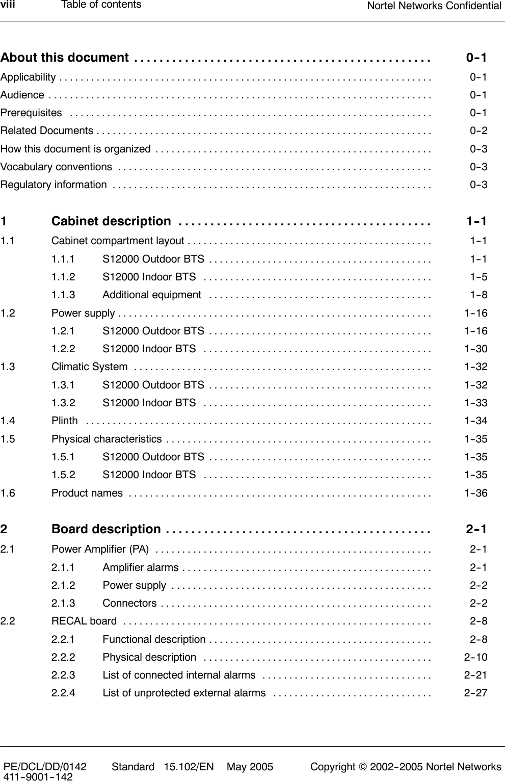
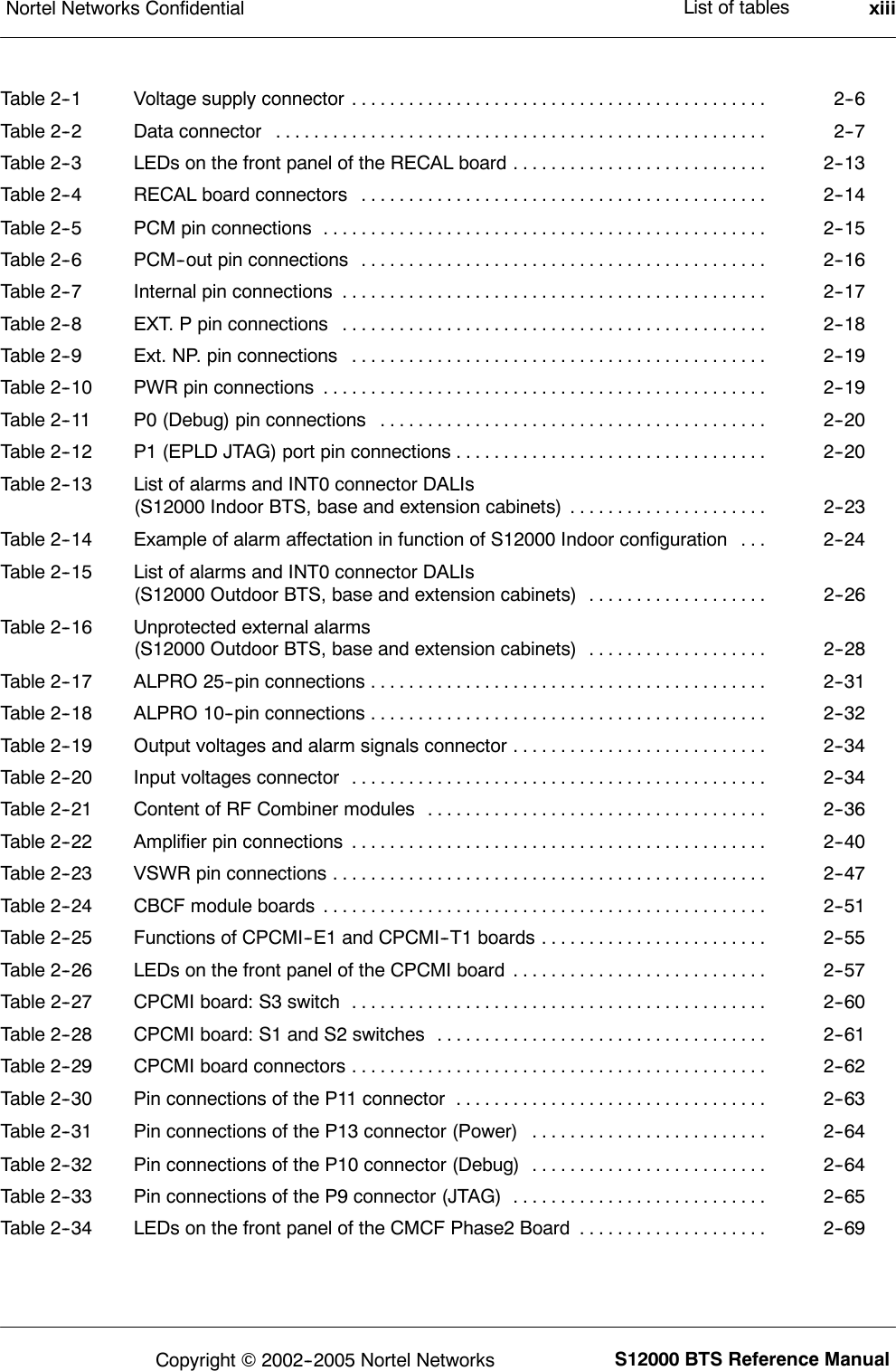
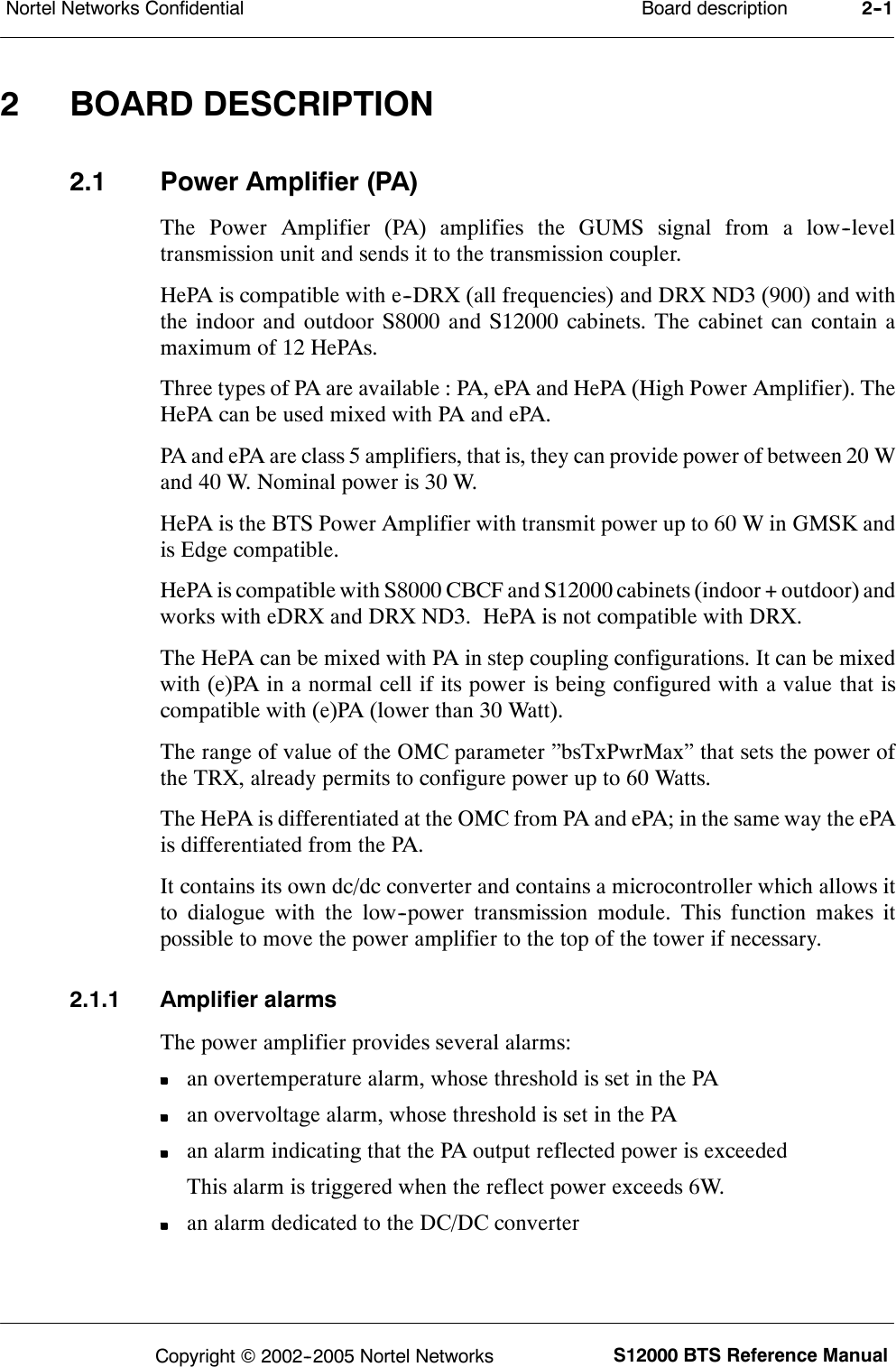
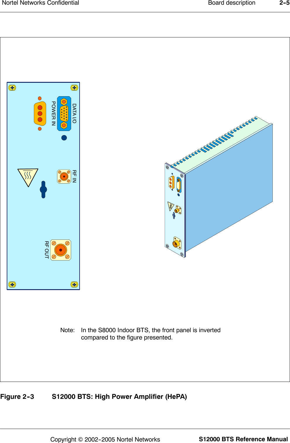
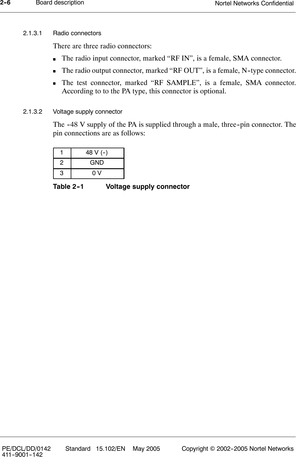
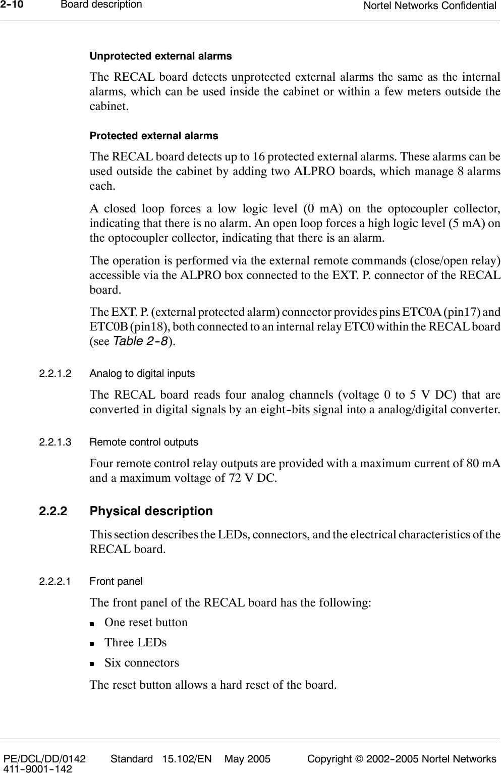
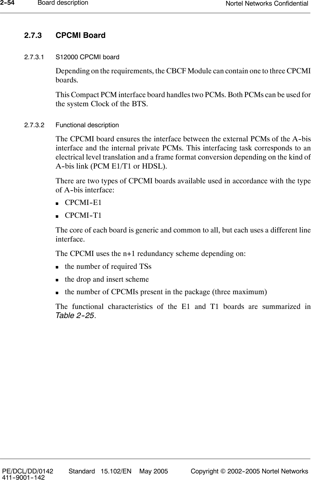
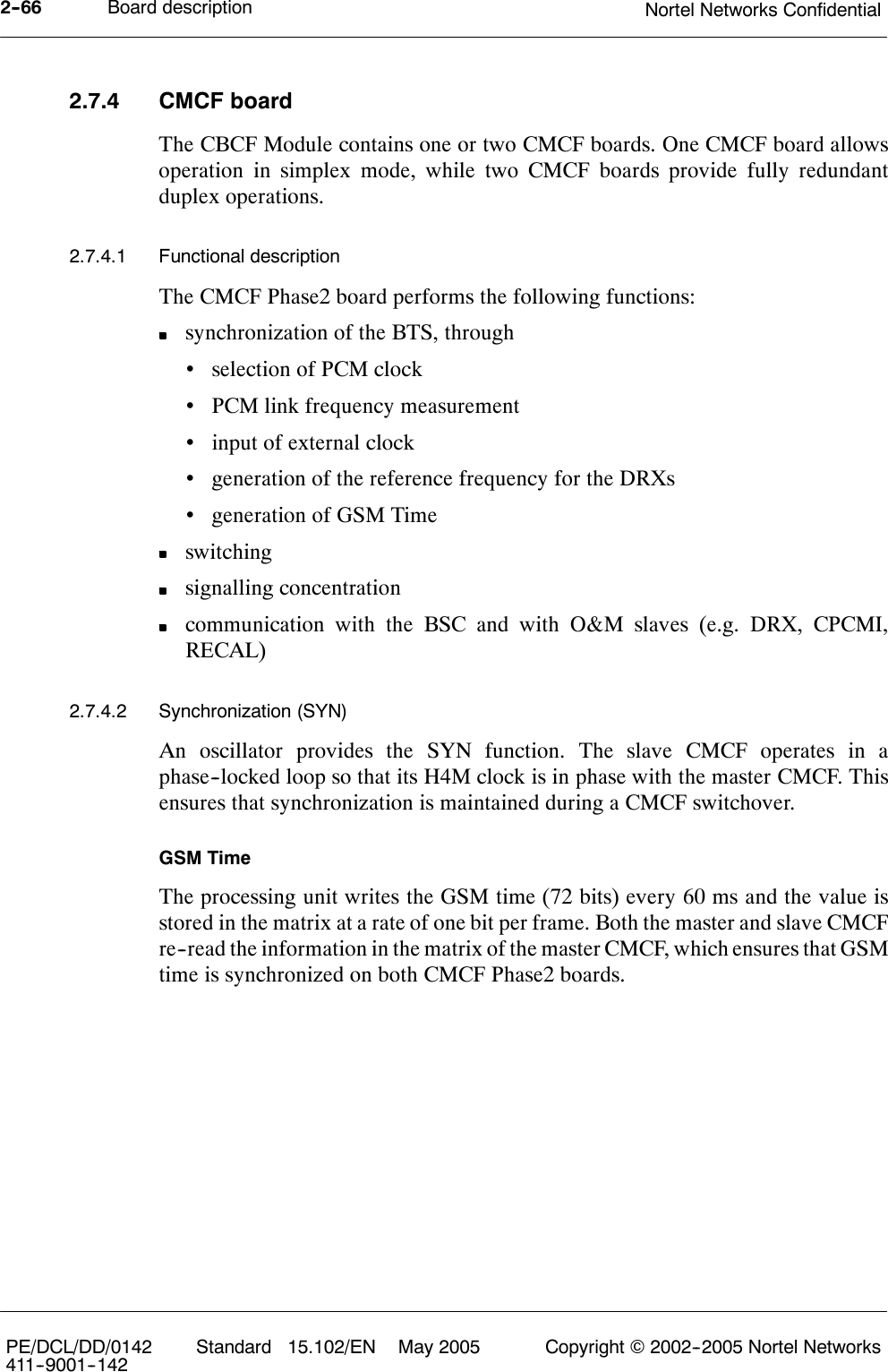
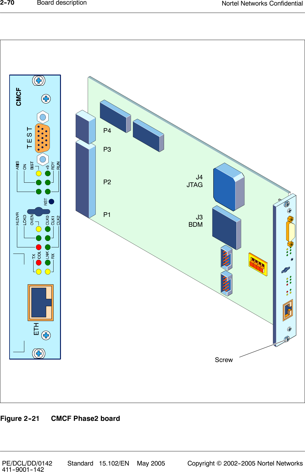
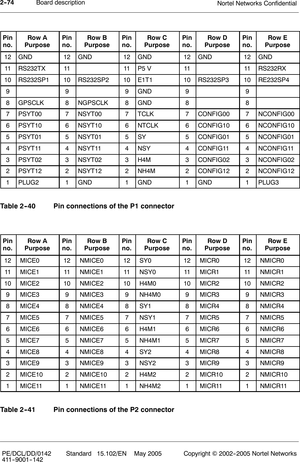
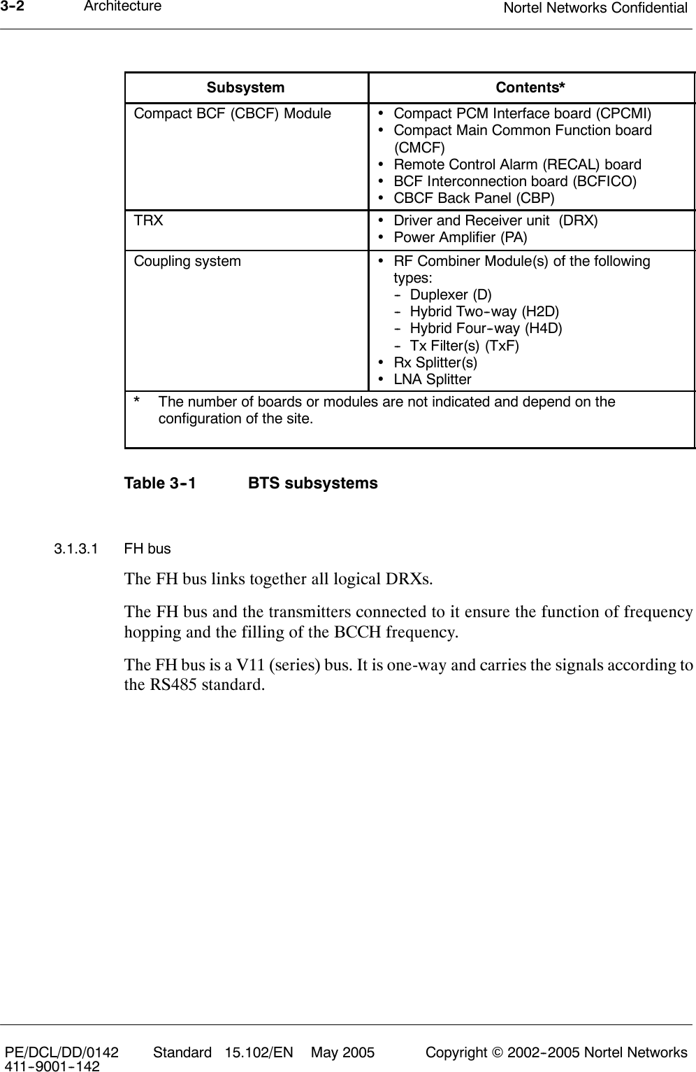
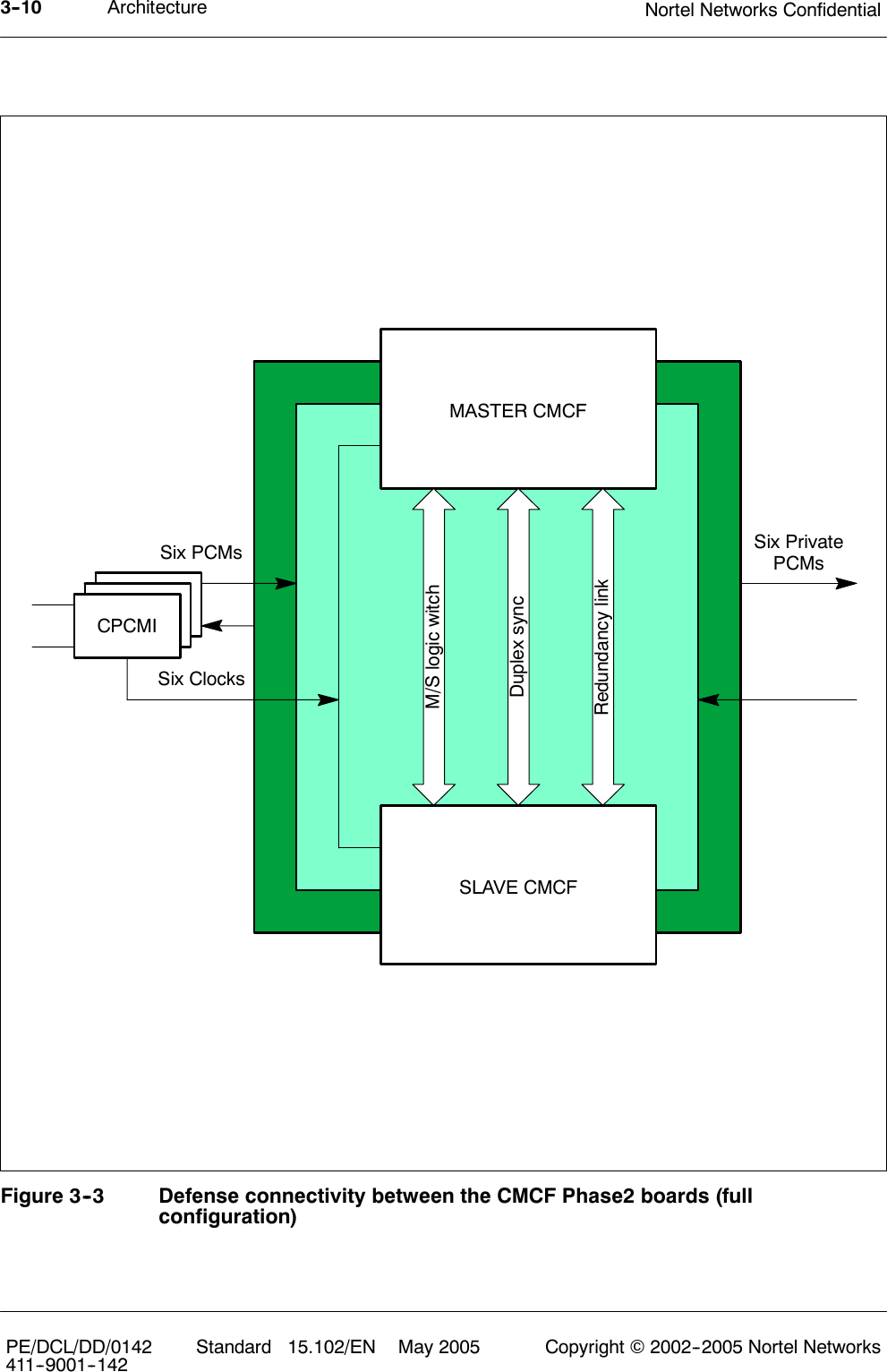
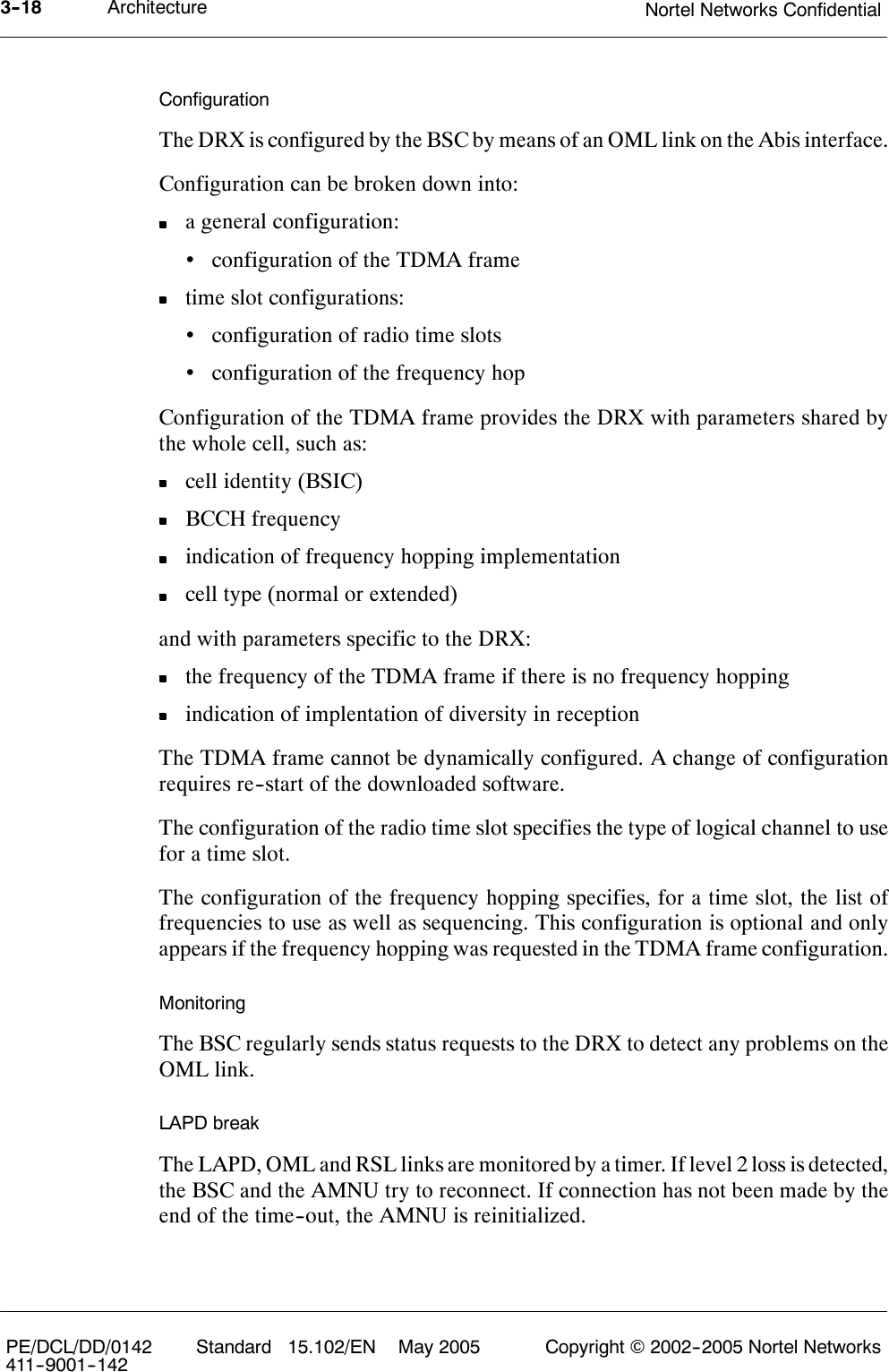
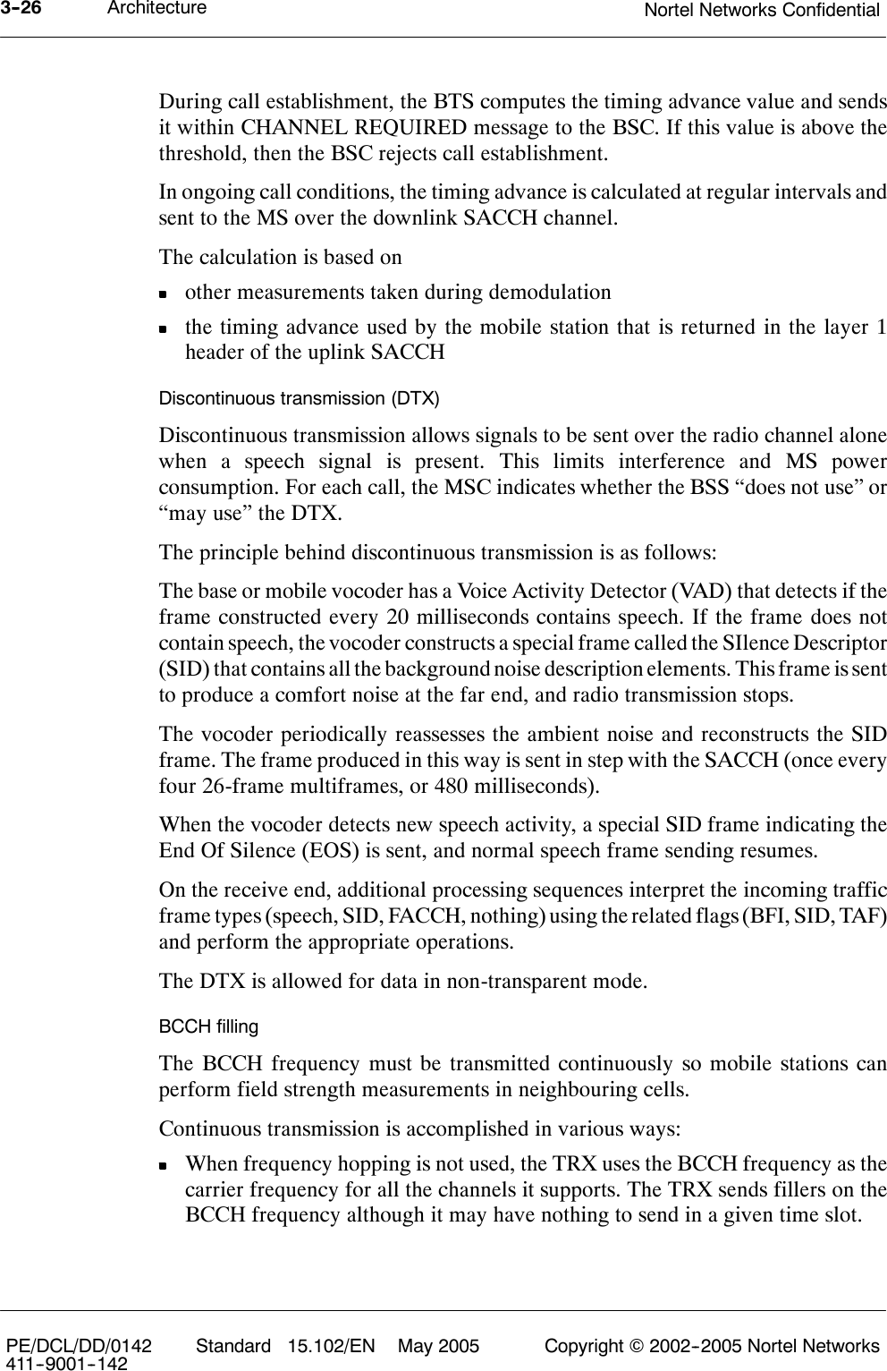
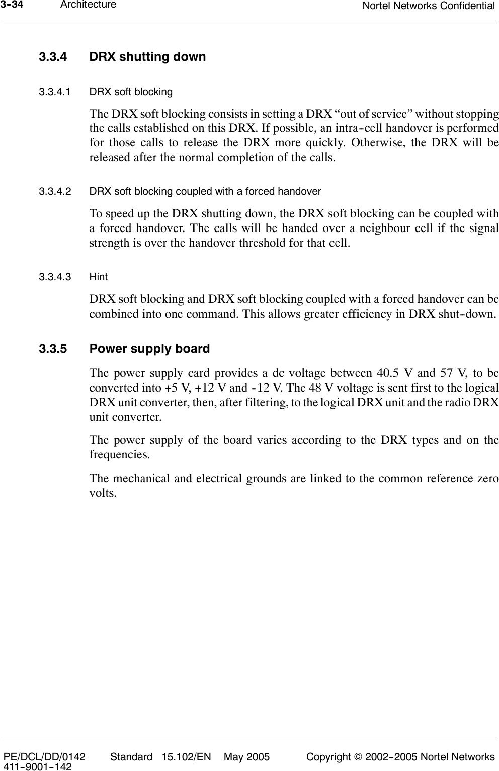
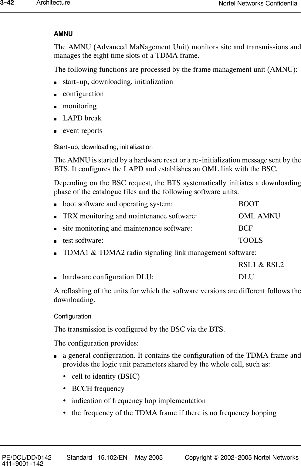
![Board descriptionNortel Networks Confidential 2--9S12000 BTS Reference ManualCopyright ©2002--2005 Nortel Networks48VDC/5VDCConversion5VDC/12VDCIsolated Conversion+5Vdc +12VDCisolatedPower supplyReset logicLEDsDebugPORTLoopbacklogicCPUioio iosci@, data/irqFlashEPROM SRAMMemory AddressdecodinglogicCabinetreferencenumberControl unitA/D channelsInternal alarmsinterfaceRemote controlExternal alarmsinterfaceHDLCcontrollerPCMinterfaceSEL[4:7]2PCMsfrom/toCavities2PCMsfrom/toCMCFs48VDCpower supply4 A/D inputs4 remotecontrol outputs88 internalalarms16 externalalarmsAlarms interface CommunicationinterfaceFigure 2--4 RECAL board functional diagram](https://usermanual.wiki/Avaya-Canada/S12000BTS/User-Guide-661112-Page-67.png)