Avaya Canada S12000BTS Base Transceiver Station User Manual 411 9001 142 15102
Avaya Canada Corporation Base Transceiver Station 411 9001 142 15102
Exhibit 8 user manual

Wireless Service Provider Solutions
S12000 BTS Reference Manual
PE/DCL/DD/0142 15.102/EN Standard May 2005
411--9001--142
Copyright ©2002--2005 Nortel Networks

< 142 > : S12000 BTS Reference Manual
Wireless Service Provider Solutions
S12000 BTS Reference Manual
Document number: PE/DCL/DD/0142
411--9001--142
Document status: Standard
Document issue: 15.102/EN
Product release: GSM/BSS V15.1
Date: May 2005
Copyright ©2002--2005 Nortel Networks, All Rights Reserved
Originated in France
NORTEL NETWORKS CONFIDENTIAL:
The information contained in this document is the property of Nortel Networks. Except as specifically authorized in
writing by Nortel Networks, the holder of this document shall keep the information contained herein confidential and
shall protect same in whole or in part from disclosure and dissemination to third parties and use for evaluation,
operation and maintenance purposes only.
You may not reproduce, represent, or download through any means, the information contained herein in any way or in
any form without prior written consent of Nortel Networks.
The following are trademarks of Nortel Networks: *NORTEL NETWORKS, the NORTEL NETWORKS corporate logo,
the NORTEL Globemark, UNIFIED NETWORKS, S2000, S4000, S8000. GSM is a trademark of France Telecom.
All other brand and product names are trademarks or registered trademarks of their respective holders.
Copyright ©2002--2005 Nortel Networks

Publication HistoryNortel Networks Confidential iii
S12000 BTS Reference Manual
Copyright ©2002--2005 Nortel Networks
PUBLICATION HISTORY
System release: GSM/BSS V15.1
May 2005
Issue 15.102/EN Standard
Removed information on BSC 6000 due to EOL.
March 2005
Issue 15.101/EN Preliminary
Synchronized with V15.01 Standard
Updated for Review Comments
January 2005
Issue 15.100/EN Draft
Section 1.6: configuration updated
Feature 25493: section 3.3.1.1 updated with information on EDGE implementation
Chapter 5: reference to document GSM/GPRS/EDGE BSS Engineering Rules
updated
System release: GSM/BSS V15.1R
November 2004
Issue 15.52/EN Preliminary
Synchronized with V15.0 Standard
August 2004
Issue 15.51/EN Preliminary
Updated with Review Comments
July 2004
Issue 15.50/EN Draft

Publication History Nortel Networks Confidential
iv
PE/DCL/DD/0142
411--9001--142 Standard 15.102/EN May 2005 Copyright ©2002--2005 Nortel Networks
Added the following statement to Section 2.1: Version 15.1R supports HePA 900
with GSM BTS.
Removed the following statements from the Applicability section: V15.0 features
are not supported on the BSC2G. BSC2G functionality is kept on BSCs running the
14.3 software load.
System release: GSM/BSS V15.0
October 2004
Issue 15.09/EN Standard
HePA updates
September 2004
Issue 15.08/EN Standard
July 2004
Issue 15.07/EN Preliminary
Updated Chapter 2 with power consumption information.
Removed customer names from August history 2003.
Issue 15.06/EN Preliminary
Updated for Helmsman release.
Issue 15.05/EN Preliminary
Added Feature 25621 to Chapter 2
May 2004
Issue 15.04/EN Preliminary
Updated according to the following feature:
24961: S12000 dual band 850/1900 E1
March 2004
Issue 15.03/EN Preliminary
Updated the power amplifier board description.

Publication HistoryNortel Networks Confidential v
S12000 BTS Reference Manual
Copyright ©2002--2005 Nortel Networks
March 2004
Issue 15.02/EN Preliminary
Up issued this manual for a preliminary release
December 2003
Issue 15.01/EN Draft
V15.0 features are not supported on the BSC2G. (BSC2G functionality is kept on
BSCs running the 14.3 software load).
Update according to the following features:
•
23068
•
24119
For Q00795093, update to Table 2--16, Chapter 2.
Update About this document regarding V15 features not supported on BSC2G.
November 2003
Issue 14.05/EN Standard
For Q00767324, added --25793: S12000 ID/OD 2S888 H4D
Update according to the following features:
•
24396: e--PA 1800 or S8000 and S12000
•
24397: e--PA 900 for S8000 and S12000
•
24381: e--PA 1900 for S8000 and S12000
•
24382: e--PA 850 for S8000 and S12000
•
24981: e--PA redesign 1900 for S8000 and S12000
•
24982: e--PA redesign 850 for S8000 and S12000
August 2003
Issue 14.04/EN Preliminary
The following changes were made throughout the document:
Update the dc power supply diagram of the S12000 outdoor BTS
Update according to the following features:
•
24915: S12000 ind/out up to 2S666/D (1 or 2) + H2D (1 or 2) with HePA/PA
•
25043: S12000 ind/outd up to 3S666/D (1 or 2) + H2D (1 or 2) with PA
•
25044: S12000 ind/out up to 3S121212/H2D (1 or 2) + H4D (1 or 2) with PA

Publication History Nortel Networks Confidential
vi
PE/DCL/DD/0142
411--9001--142 Standard 15.102/EN May 2005 Copyright ©2002--2005 Nortel Networks
•
23849: S12000 1800/T1
•
24963: S12000 850/E1
•
24964: S12000 1900/E1
•
25248: S12K -- 900Mhz/T1
•
24399: eDRX 900 for S8000 and S12000
April 2003
Issue 14.03/EN Preliminary
The following changes were made throughout the document:
Update power supply description of the S12000 outdoor BTS
Update GIPS description
Add frequency band configuration in chapter 1
January 2003
Issue 14.02/EN Preliminary
The following changes were made throughout the document:
Modify the DCU description
Modify the GIPS front face
December 2002
Issue 14.01/EN Preliminary
The following changes were made throughout the document:
Upgrade according to the following feature:
•
PR1505: S8000/S12000 High Power PA (60W)
•
22472: S12000 configuration priority 2
•
SV1374: Network Level Identification of e--DRL and e--PA presence
Add the GIPS module and the associated AC box
Add the four--way hybrid duplexer (H4D 1900 Mhz) RF Combiner
System release: GSM/BSS V13
October 2002
Issue 13.05/EN Standard

Publication HistoryNortel Networks Confidential vii
S12000 BTS Reference Manual
Copyright ©2002--2005 Nortel Networks
Update according to the V13.2b task force
September 2002
Issue 13.04/EN Preliminary
Update after internal review
August 2002
Issue 13.03/EN Preliminary
Update after internal review
The following changes were made after internal review
900 and 1800 Mhz features were removed
all references to DRX were changed to e--DRX
all references to PA were changed to e--PA
all references to C--DCS and LNS--DCS were removed
all references to single--phase and tri--phase AC boxes were removed
The following checks have been performed:
battery threshold of the PCU
functioning temperature of the rectifiers
values of the PCU breaker (modified)
values of the indoor compartment breaker (modified)
nominal output voltage and output voltage range of the rectifier subrack
July 2002
Issue 13.02/EN Draft
Creation
March 2002
Issue 13.01/EN Draft
Creation

Table of contents Nortel Networks Confidential
viii
PE/DCL/DD/0142
411--9001--142 Standard 15.102/EN May 2005 Copyright ©2002--2005 Nortel Networks
About this document 0--1...............................................
Applicability 0--1......................................................................
Audience 0--1........................................................................
Prerequisites 0--1....................................................................
Related Documents 0--2...............................................................
How this document is organized 0--3....................................................
Vocabulary conventions 0--3...........................................................
Regulatory information 0--3............................................................
1 Cabinet description 1--1........................................
1.1 Cabinet compartment layout 1--1..............................................
1.1.1 S12000 Outdoor BTS 1--1..........................................
1.1.2 S12000 Indoor BTS 1--5...........................................
1.1.3 Additional equipment 1--8..........................................
1.2 Power supply 1--16...........................................................
1.2.1 S12000 Outdoor BTS 1--16..........................................
1.2.2 S12000 Indoor BTS 1--30...........................................
1.3 Climatic System 1--32........................................................
1.3.1 S12000 Outdoor BTS 1--32..........................................
1.3.2 S12000 Indoor BTS 1--33...........................................
1.4 Plinth 1--34.................................................................
1.5 Physical characteristics 1--35..................................................
1.5.1 S12000 Outdoor BTS 1--35..........................................
1.5.2 S12000 Indoor BTS 1--35...........................................
1.6 Product names 1--36.........................................................
2 Board description 2--1..........................................
2.1 Power Amplifier (PA) 2--1....................................................
2.1.1 Amplifier alarms 2--1...............................................
2.1.2 Power supply 2--2.................................................
2.1.3 Connectors 2--2...................................................
2.2 RECAL board 2--8..........................................................
2.2.1 Functional description 2--8..........................................
2.2.2 Physical description 2--10...........................................
2.2.3 List of connected internal alarms 2--21................................
2.2.4 List of unprotected external alarms 2--27..............................

Table of contents
Nortel Networks Confidential ix
S12000 BTS Reference Manual
Copyright ©2002--2005 Nortel Networks
2.3 ALPRO board 2--29..........................................................
2.3.1 Principle 2--29.....................................................
2.3.2 Description 2--29...................................................
2.3.3 S12000 Outdoor BTS environmental conditions 2--29...................
2.3.4 S12000 Indoor BTS environmental conditions 2--31.....................
2.3.5 Connectors 2--31...................................................
2.4 F--type converter 2--33.......................................................
2.4.1 Principle 2--33.....................................................
2.4.2 Description 2--33...................................................
2.4.3 Front panel 2--34...................................................
2.5 RF Combiner 2--36...........................................................
2.5.1 Principle 2--36.....................................................
2.5.2 RF Combiner front panels 2--42......................................
2.6 Tx--Filter module 2--48........................................................
2.6.1 VSWR--meter 2--48.................................................
2.7 Compact BCF (CBCF) module 2--51............................................
2.7.1 Functional description 2--51..........................................
2.7.2 Physical description 2--52...........................................
2.7.3 CPCMI Board 2--54.................................................
2.7.4 CMCF board 2--66.................................................
2.7.5 BCFICO board 2--76................................................
2.7.6 CBCF Back Panel (CBP) 2--86.......................................
2.8 DRX, e--DRX, or DRX--ND3 module 2--95.......................................
2.8.1 DRX front panel 2--95...............................................
2.8.2 e--DRX front panel 2--97.............................................
2.9 RX--splitter 2--99.............................................................
2.9.1 Principle 2--99.....................................................
2.9.2 Consumption 2--99.................................................
2.9.3 RX--splitter front panel 2--99.........................................
2.10 Power system 2--104..........................................................
2.10.1 Power system description 2--104......................................
2.10.2 PCU description 2--104...............................................
2.10.3 SRU description 2--109...............................................
2.10.4 GIPS description 2--110..............................................
3 Architecture 3--1...............................................
3.1 Physical architecture 3--1....................................................
3.1.1 Introduction 3--1..................................................

Table of contents Nortel Networks Confidential
x
PE/DCL/DD/0142
411--9001--142 Standard 15.102/EN May 2005 Copyright ©2002--2005 Nortel Networks
3.1.2 Subsystems 3--1..................................................
3.1.3 Internal buses 3--1................................................
3.2 CBCF functional architecture 3--5.............................................
3.2.1 Switching, synchronization, and concentration 3--5.....................
3.2.2 Control of the alarm management unit 3--11...........................
3.2.3 PCM Interface 3--11................................................
3.3 DRX functional architecture 3--13..............................................
3.3.1 Types of DRX boards 3--13..........................................
3.3.2 DRX digital part 3--13...............................................
3.3.3 DRX radio part 3--31................................................
3.3.4 DRX shutting down 3--34............................................
3.3.5 Power supply board 3--34...........................................
3.4 e--DRX functional architecture 3--35............................................
3.4.1 Modifications between the DRX and e--DRX 3--35......................
3.4.2 Main external connections 3--37......................................
3.4.3 e--DRX functional description 3--38...................................
4 Software descrIption 4--1.......................................
4.1 BTS software presentation 4--1...............................................
4.1.1 Downloadable files 4--1............................................
4.1.2 PROM 4--1.......................................................
4.2 BTS software functions 4--3..................................................
4.2.1 DRX software functions 4--3.......................................
4.2.2 CBCF software functions 4--7.......................................
4.2.3 Maintenance 4--9..................................................
4.2.4 TIL software functions 4--10.........................................
5 Dimensioning rules 5--1........................................

List of figures
Nortel Networks Confidential xi
S12000 BTS Reference Manual
Copyright ©2002--2005 Nortel Networks
Figure 1--1 S12000 Outdoor BTS: Base cabinet layout 1--2............................
Figure 1--2 S12000 Indoor BTS: Base cabinet layout 1--6..............................
Figure 1--3 External battery cabinet of the S12000 Outdoor BTS (SBS 60 batteries) 1--9...
Figure 1--4 External battery cabinet of the S12000 Outdoor BTS (SBS C11 batteries) 1--10.
Figure 1--5 S12000 Indoor BTS: Cabinet top 1--12.....................................
Figure 1--6 S12000 Outdoor BTS: PCM connection box 1--13...........................
Figure 1--7 S12000 Outdoor BTS: --48 V connection box 1--14...........................
Figure 1--8 External alarm connection box 1--15.......................................
Figure 1--9 S12000 Outdoor BTS: dc power supply diagram 1--19........................
Figure 1--10 Split single phase ac box 1--23............................................
Figure 1--11 Side view of inside of split single--phase ac box 1--24.........................
Figure 1--12 AC box/GIPS with US type user AC plug BTS 1--27..........................
Figure 1--13 AC box/GIPS with E, F, UK type user AC plug 1--28..........................
Figure 1--14 Side view of inside of AC box/GIPS 1--29...................................
Figure 1--15 S12000 Indoor BTS: dc power supply diagram 1--31.........................
Figure 2--1 S12000 BTS: Power Amplifier (type 1) 2--3................................
Figure 2--2 S12000 BTS: Power Amplifier (type 2) 2--4................................
Figure 2--3 S12000 BTS: High Power Amplifier (HePA) 2--5............................
Figure 2--4 RECAL board functional diagram 2--9.....................................
Figure 2--5 RECAL board 2--12......................................................
Figure 2--6 ALPRO board 2--30......................................................
Figure 2--7 F--type converter 2--35...................................................
Figure 2--8 Duplexer--only (D) RF Combiner diagram 2--37..............................
Figure 2--9 H2D RF Combiner diagram 2--38..........................................
Figure 2--10 H4D RF Combiner diagram 2--39..........................................
Figure 2--11 Duplexer--only (D) RF Combiner 2--43......................................
Figure 2--12 Two--way hybrid duplexer (H2D) RF Combiner 2--44.........................
Figure 2--13 Four--way hybrid duplexer (H4D 1800/900 Mhz) RF Combiner 2--45............
Figure 2--14 Four--way hybrid duplexer (H4D 850/1900 MHz) RF Combiner 2--46...........
Figure 2--15 Tx--Filter (Tx--F) module 2--49.............................................
Figure 2--16 Tx--Filter (Tx--F) functional diagram 2--50...................................
Figure 2--17 S12000 BTS: CBCF module 2--53.........................................
Figure 2--18 CPCMI board functional diagram 2--56.....................................
Figure 2--19 CPCMI board 2--58......................................................
Figure 2--20 CPCMI board: hardware switches 2--60....................................

List of figures Nortel Networks Confidential
xii
PE/DCL/DD/0142
411--9001--142 Standard 15.102/EN May 2005 Copyright ©2002--2005 Nortel Networks
Figure 2--21 CMCF Phase2 board 2--70...............................................
Figure 2--22 BCFICO board 2--77.....................................................
Figure 2--23 CBP board 2--87........................................................
Figure 2--24 DRX module 2--96.......................................................
Figure 2--25 e--DRX module 2--98.....................................................
Figure 2--26 RX--splitter diagram type 1x4 2--100........................................
Figure 2--27 RX--splitter diagram type 2x2 2--101........................................
Figure 2--28 RX--splitter type 1x4 2--102................................................
Figure 2--29 Rx--splitter type 2x2 2--103................................................
Figure 2--30 Power supply rack (seven--rectifier type) 2--108...............................
Figure 2--31 GIPS 2--114.............................................................
Figure 2--32 DCU module 2--115.......................................................
Figure 2--33 ADU module 2--116.......................................................
Figure 3--1 Subsystem architecture with CBCF 3--3...................................
Figure 3--2 CMCF board synchronization (full configuration) 3--7........................
Figure 3--3 Defense connectivity between the CMCF Phase2 boards (full configuration) 3--10
Figure 3--4 DRX board: functional block diagram 3--15..................................
Figure 3--5 AMNU functions 3--16....................................................
Figure 3--6 DCU8 unit diagram 3--22.................................................
Figure 3--7 SPU reception functions 3--24.............................................
Figure 3--8 SPU transmission functions 3--24..........................................
Figure 3--9 Power slaving diagram 3--30..............................................
Figure 3--10 e--DRX board: functional block diagram 3--36...............................
Figure 3--11 Logic unit (e--LDRX): functional architecture 3--40...........................
Figure 3--12 Radio unit (e--RDRX): functional unit 3--47..................................
Figure 4--1 Software functions (with CBCF) 4--4......................................
Figure 4--2 COAM architecture on the CBCF 4--8.....................................

List of tables
Nortel Networks Confidential xiii
S12000 BTS Reference Manual
Copyright ©2002--2005 Nortel Networks
Table 2--1 Voltage supply connector 2--6............................................
Table 2--2 Data connector 2--7....................................................
Table 2--3 LEDs on the front panel of the RECAL board 2--13...........................
Table 2--4 RECAL board connectors 2--14...........................................
Table 2--5 PCM pin connections 2--15...............................................
Table 2--6 PCM--out pin connections 2--16...........................................
Table 2--7 Internal pin connections 2--17.............................................
Table 2--8 EXT. P pin connections 2--18.............................................
Table 2--9 Ext. NP. pin connections 2--19............................................
Table 2--10 PWR pin connections 2--19...............................................
Table 2--11 P0 (Debug) pin connections 2--20.........................................
Table 2--12 P1 (EPLD JTAG) port pin connections 2--20.................................
Table 2--13 List of alarms and INT0 connector DALIs
(S12000 Indoor BTS, base and extension cabinets) 2--23.....................
Table 2--14 Example of alarm affectation in function of S12000 Indoor configuration 2--24...
Table 2--15 List of alarms and INT0 connector DALIs
(S12000 Outdoor BTS, base and extension cabinets) 2--26...................
Table 2--16 Unprotected external alarms
(S12000 Outdoor BTS, base and extension cabinets) 2--28...................
Table 2--17 ALPRO 25--pin connections 2--31..........................................
Table 2--18 ALPRO 10--pin connections 2--32..........................................
Table 2--19 Output voltages and alarm signals connector 2--34...........................
Table 2--20 Input voltages connector 2--34............................................
Table 2--21 Content of RF Combiner modules 2--36....................................
Table 2--22 Amplifier pin connections 2--40............................................
Table 2--23 VSWR pin connections 2--47..............................................
Table 2--24 CBCF module boards 2--51...............................................
Table 2--25 Functions of CPCMI--E1 and CPCMI--T1 boards 2--55........................
Table 2--26 LEDs on the front panel of the CPCMI board 2--57...........................
Table 2--27 CPCMI board: S3 switch 2--60............................................
Table 2--28 CPCMI board: S1 and S2 switches 2--61...................................
Table 2--29 CPCMI board connectors 2--62............................................
Table 2--30 Pin connections of the P11 connector 2--63.................................
Table 2--31 Pin connections of the P13 connector (Power) 2--64.........................
Table 2--32 Pin connections of the P10 connector (Debug) 2--64.........................
Table 2--33 Pin connections of the P9 connector (JTAG) 2--65...........................
Table 2--34 LEDs on the front panel of the CMCF Phase2 Board 2--69....................

List of tables Nortel Networks Confidential
xiv
PE/DCL/DD/0142
411--9001--142 Standard 15.102/EN May 2005 Copyright ©2002--2005 Nortel Networks
Table 2--35 CMCF Phase2 board connectors 2--71.....................................
Table 2--36 Pin connections of the TEST connector 2--72...............................
Table 2--37 Pin connections of the ETH connector 2--72.................................
Table 2--38 Pin connections of the J3 (BDM) connector 2--73............................
Table 2--39 Pin connections of the J4 (JTAG) Connector 2--73...........................
Table 2--40 Pin connections of the P1 connector 2--74..................................
Table 2--41 Pin connections of the P2 connector 2--74..................................
Table 2--42 Pin connections of the P3 connector 2--75..................................
Table 2--43 Pin connections of the P4 (Power) connector 2--75...........................
Table 2--44 BCFICO board connectors 2--76..........................................
Table 2--45 PCM0/1 pin connections 2--78............................................
Table 2--46 PCM2/3 pin connections 2--79............................................
Table 2--47 PCM4/5 pin connections 2--79............................................
Table 2--48 ABIS pin connections 2--80...............................................
Table 2--49 PWR pin connections 2--80...............................................
Table 2--50 RS232 pin connections 2--81..............................................
Table 2--51 J2 pin connections 2--81..................................................
Table 2--52 J4 pin connections 2--82..................................................
Table 2--53 J6 pin connections 2--82..................................................
Table 2--54 J7 pin connections 2--83..................................................
Table 2--55 TEI Resistor coding on the switch register 2--84.............................
Table 2--56 TEI configuration 2--85...................................................
Table 2--57 CMCF_A (Sign1A) pin connections 2--88...................................
Table 2--58 CMCF_A (Sign1B) pin connections 2--89...................................
Table 2--59 CMCF_A (Sign1C) pin connections 2--89...................................
Table 2--60 CMCF_B (Sign2A) pin connections 2--90...................................
Table 2--61 CMCF_B (Sign2B) pin connections 2--90...................................
Table 2--62 CMCF_B (Sign2C) pin connections 2--91...................................
Table 2--63 CPCMI_0 (Sign3) pin connections 2--91....................................
Table 2--64 CPCMI_1 (Sign 4) pin connections 2--92...................................
Table 2--65 CPCMI_2 (Sign 5) pin connections 2--92...................................
Table 2--66 BCFICO (Sign6A) pin connections 2--93....................................
Table 2--67 BCFICO (Sign6B) pin connections 2--93....................................
Table 2--68 BCFICO (Sign6C) pin connections 2--94....................................
Table 2--69 AL1, AL2, AL3, AL4, AL5, AL6 pin connections
(Power voltage connectors) 2--94..........................................

List of tables
Nortel Networks Confidential xv
S12000 BTS Reference Manual
Copyright ©2002--2005 Nortel Networks
Table 2--70 Alarm connector 2--105...................................................
Table 2--71 Monitoring connector 2--106...............................................
Table 2--72 Alarm connector 2--111...................................................
Table 3--1 BTS subsystems 3--2...................................................
Table 4--1 CBCF software product names 4--1.......................................
Table 4--2 S12000 BTS family : DRX software product names 4--2.....................
About this documentNortel Networks Confidential 0--1
S12000 BTS Reference Manual
Copyright ©2002--2005 Nortel Networks
ABOUT THIS DOCUMENT
This document describes the S12000 Indoor and Outdoor Base Transceiver Stations
(BTSs), which are components of the Base Station Subsystem (BSS).
Applicability
This document is part of the BSS Nortel Networks Technical Publications (NTPs).
This document applies to the V15.1 BSS system release.
The S12000 BTS supports the following frequencies:
Single band GSM 850 T1/E1, 900 T1, 1800 T1 and 1900 T1/E1
Dual band GSM 850/1900 T1/E1
CAUTION
GSM--R does not apply to the S12000 BTS.
Audience
This document is for operations and maintenance personnel, and for other users who
want to know more about the BTSs.
Prerequisites
It is recommended that the readers also become familiar with the following
documents:
< 01 > : BSS Overview
< 07 > : BSS Operating Principles
< 124 > : BSS Parameter Dictionary
< 125 > : Observation Counter Dictionary
< 128 > : OMC--R User Manual -- Volume 1 of 3: Object and Fault menus
< 129 > : OMC--R User Manual -- Volume 2 of 3: Configuration, Performance,
and Maintenance menus

About this document Nortel Networks Confidential
0--2
PE/DCL/DD/0142
411--9001--142 Standard 15.102/EN May 2005 Copyright ©2002--2005 Nortel Networks
< 130 > : OMC--R User Manual -- Volume 3 of 3: Security, Administration,
SMS--CB, and Help menus
< 143 > : S12000 BTS Fault Numbers
< 144 > : S12000 BTS Maintenance Manual
Document GSM/GPRS/EDGE BSS Engineering Rules (PE/DCL/DD/0138)
Related Documents
The NTPs listed in the above paragraph are quoted in the document.

About this documentNortel Networks Confidential 0--3
S12000 BTS Reference Manual
Copyright ©2002--2005 Nortel Networks
How this document is organized
Chapter 1 describes the layout and contents of the BTS cabinets.
Chapter 2 describes the functions of the BTS boards and modules, and also describes
their front panels.
Chapter 3 examines BTS architecture and describes the physical structure, focusing
on the functional architecture of the subsystems.
Chapter 4 lists BTS software entities and shows how they are installed on the
hardware units.
Chapter 5 indicates that the dimensioning rules are now contained in GSM BSS
Engineering Rules document.
Vocabulary conventions
The glossary is included in the NTP < 00 >.
Regulatory information
Refer to the NTP < 01 >.

Cabinet descriptionNortel Networks Confidential 1--1
S12000 BTS Reference Manual
Copyright ©2002--2005 Nortel Networks
1 CABINET DESCRIPTION
1.1 Cabinet compartment layout
1.1.1 S12000 Outdoor BTS
The base cabinet and the extension cabinet are divided into three parts:
top compartment
left side
right side
The layout of the equipment in the base and extension cabinets is identical in the
top compartment and on the left side.
The cabinet layout on the right side of the base and extension cabinets is different.
In the base cabinet, the CBCF is located in the CBCF compartment. In the same
compartment of the extension cabinet, a filling plate replaces the CBCF.
The top compartment opens by means of a cover on the top of the cabinet. The front
of the cabinet is perforated to allow air to circulate. The top compartment has two
elements: the optional battery box and the climatic system (DACS).
User compartment
This compartment is available for Original Equipment Manufacturer (OEM). For
more information, refer to the documentation provided by the equipment
manufacturer.
The user interconnection compartment is optional. It is required only when a user
kit or a --48 V connection box is used.
PA interconnection compartment
The PA interconnection compartment centralizes the --48 V dc power supply of the
Power Amplifiers (PA).
Amplifier compartment
The amplifier compartment receives up to twelve Power Amplifiers (PA).
RECAL compartment
This compartment contains the RECAL board. The RECAL board is connected to
one or two external alarm protection boards (ALPRO), located outside the cabinet.
Cabinet description Nortel Networks Confidential
1--2
PE/DCL/DD/0142
411--9001--142 Standard 15.102/EN May 2005 Copyright ©2002--2005 Nortel Networks
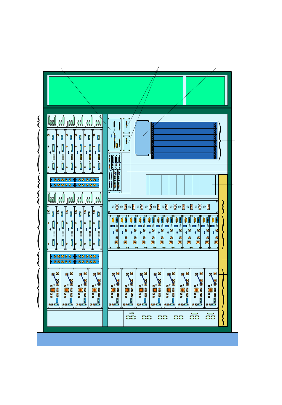
DRX--ICOA
DRX
4RX splitters
DRX--ICO B
DRX
4RX splitters
User rack
CBCF
Power system
PA--ICO
DACS Batteries
RECAL 2 F--type converters User interconnections
Filler
12 PA
AC box
COM--ICO
8 RF--combiners
Filler
Filler
01 2 34 5
67891011
01 2 34 5
67891011
4RF--
combiners
rack
Figure 1--1 S12000 Outdoor BTS: Base cabinet layout

Cabinet descriptionNortel Networks Confidential 1--3
S12000 BTS Reference Manual
Copyright ©2002--2005 Nortel Networks
F--type converter
A converter, called F--type converter, supplies ±15 V dc to the LNA--splitter and
the VSWR--meter.
A second F--type converter is available as an option.
RF Combiner and Tx--Filter compartments
The RF Combiner and Tx--Filter compartments can hold a maximum of either of
the following combination of modules (4 on the left, 8 on the right):
twelve RF duplexer (D) plus LNAs
twelve RF duplexer (D) plus LNAs plus Tx--Filter modules
twelve two--way RF Hybrid Duplexer type (H2D) plus LNAs
six RF four--way Hybrid Duplexer type (H4D) plus LNAs
Note: Depending on the coupling system used, an RF--combiner can contain a
duplexer, an H2D or H4D transmitter coupler, an LNA splitter, and an optional
VSWR meter.
The D, H2D, and H4D RF Combiner modules perform the following functions:
transmission coupling of two, three, or four channels
filtering and duplexing of transmission and reception signals on the same
antenna port
amplification of reception signals
monitoring of the antenna VSWR (option)
The Tx--Filter performs the following functions:
filtering of transmission signals
monitoring of the antenna VSWR (option)
Combiner interconnection compartment (COMICO)
The COMICO is the interconnection board for the modules of the RF Combiner
compartment that centralizes inputs/outputs on the alarms and the power supplies.
COMICO collects and connects alarms to RECAL.
CBCF Compartment
Two CBCF boards are visible on the front panel of the CBCF module:
Compact Main Common Function (CMCF)
Compact PCMI (CPMI)
Since there is no CBCF in the extension cabinet, a filling plate occupies the place
of these units.

Cabinet description Nortel Networks Confidential
1--4
PE/DCL/DD/0142
411--9001--142 Standard 15.102/EN May 2005 Copyright ©2002--2005 Nortel Networks
DRX interconnection compartments (DRX--ICO A and DRX--ICO B)
The interconnection compartments centralize DRX outputs. They assure
interconnection between DRX via the FH bus, PA, RECAL and CBCF modules.
DRX compartments
These compartments receive up to twelve modules, 6 in each.
RX--splitter compartments
The RX--splitter compartments receive up to eight RX--splitters, which receive RF
signals from the LNA splitter and distribute them to the DRXs RX inputs.
Power system compartment
The power system compartment may be configured with:
a Power Controller Unit (PCU) and up to seven 600W or 680W rectifiers (one of
them redundant).
or a GIPS module including a DC Distribution and Control Unit (DCU), up to
seven 680W rectifiers (one of them redundant), and an AC Distribution Unit
(ADU).
The rectifiers convert Mains Voltage to --48 V dc to be used in the cabinet.
According to the number of DRXs per cell, the number of rectifiers may be
decreased.
AC box
This box is located on the right--hand side of the right--hand part of the cabinet. Two
types of AC box are available:
The AC box associated with the power system with PCU. It receives the mains
voltage and distributes it to the power system compartment and to the cooling
system. The PCU only controls the dc supply. The ac supply connects to the back
panel, which is common for all rectifiers.
The AC box/GIPS associated with the GIPS. It receives the mains voltage and
distributes it to the power system compartment and to the user ac plug.

Cabinet descriptionNortel Networks Confidential 1--5
S12000 BTS Reference Manual
Copyright ©2002--2005 Nortel Networks
1.1.2 S12000 Indoor BTS
The compartment layout of the base cabinet is presented in Figure 1--2.
Cabinet top
The cabinet top (see Figure 1--5) can hold a maximum of two ALPRO modules.
An ALPRO module consists of an ALPRO board, a protection cover, and an
interconnection plate.
Combiner interconnection (COMICO) compartment
This compartment consists of an interconnection board for the combiner
compartment modules, which centralizes inputs/outputs on the alarms and the
power supplies.
RF combiner and Tx--Filter compartment
The RF Combiner and Tx--filter compartment can hold a maximum of either of the
following combination of modules:
twelve RF duplexer (D) plus LNAs
twelve RF duplexer (D) plus LNAs plus Tx--Filter modules
twelve two--way RF Hybrid Duplexer type (H2D) plus LNAs
six RF four--way Hybrid Duplexer type (H4D) plus LNAs
Note: Depending on the coupling system used, an RF--combiner can contain a
duplexer, an H2D or H4D transmitter coupler, an LNA splitter, and an optional
VSWR meter.
The RF Combiner modules perform the following functions:
transmission coupling of the channels
filtering and duplexing of transmission and reception signals on the same
antenna port
amplification of reception signals
monitoring of the antenna VSWR (option)
The Tx--Filter performs the following functions:
filtering of transmission signals
monitoring of the antenna VSWR (option)
Cabinet description Nortel Networks Confidential
1--6
PE/DCL/DD/0142
411--9001--142 Standard 15.102/EN May 2005 Copyright ©2002--2005 Nortel Networks
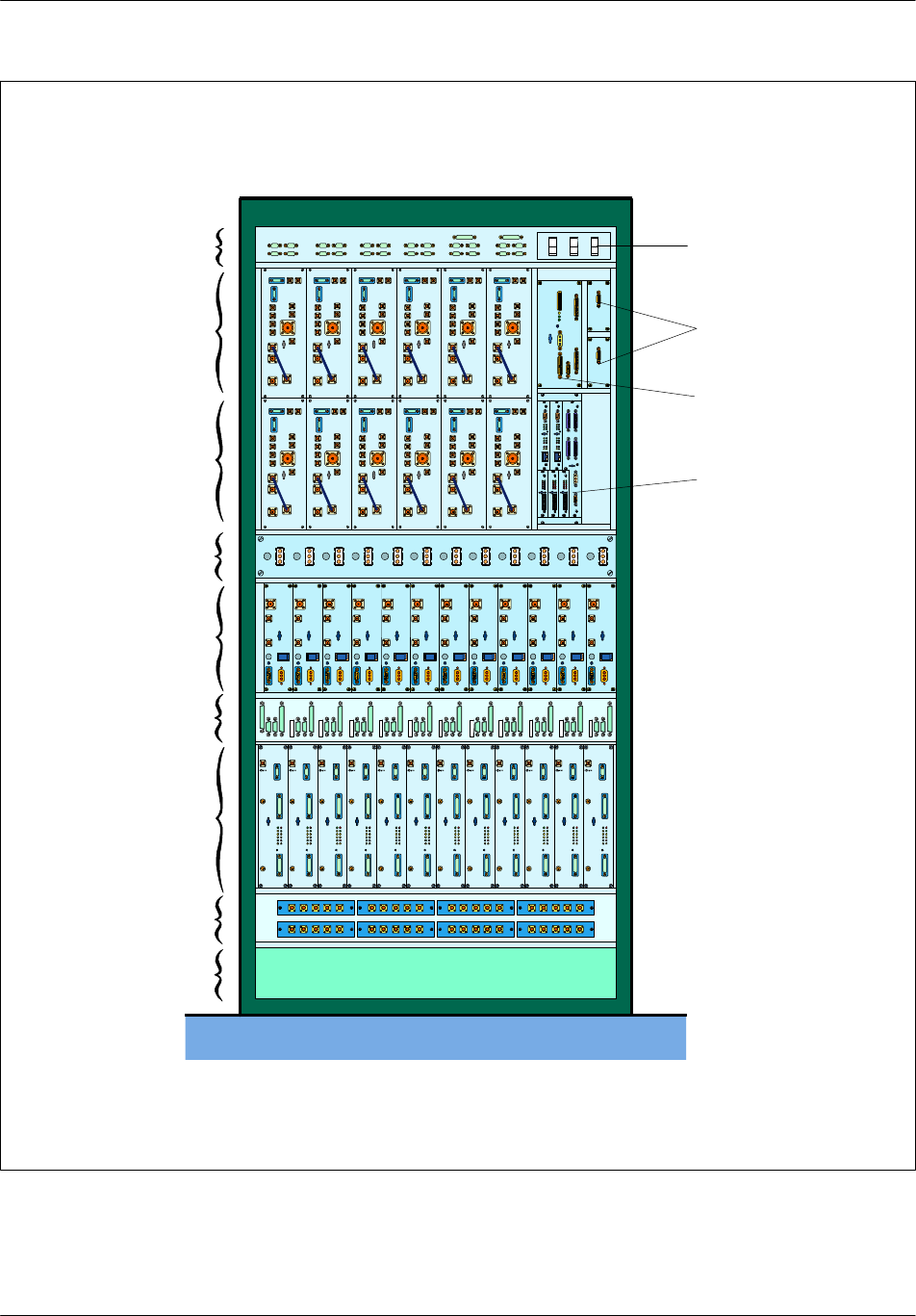
8 RX Splitters
12 DRX
DRX--ICO
12 PA
PA--ICO
6 RF--combiners
COM--ICO Breakers
2F--type converters
RECAL
CBCF
6 RF--combiners
Internal Cooling
System
0123 456 7891011
0123 456 7891011
Figure 1--2 S12000 Indoor BTS: Base cabinet layout

Cabinet descriptionNortel Networks Confidential 1--7
S12000 BTS Reference Manual
Copyright ©2002--2005 Nortel Networks
DC compartment
This compartment contains three switches to disconnect the power supply to the
Power Amplifiers, the fans, and the RECAL/CBCF board.
F--type converters
The compartment also contains an F--type converter, which supplies ±15 V dc to
the LNA--splitter and the VSWR--meter. A second F--type converter is available as
an option.
PA interconnection compartment
This compartment centralizes the --48 V dc power supply of the Power Amplifiers
(PA).
Power Amplifier compartment
This compartment contains one to twelve power amplifiers (PAs).
RECAL board
The RECAL board can be connected to one or two external alarm protection boards
(ALPRO) located on top of the base cabinet.
DRX interconnection compartment
This compartment centralizes DRX outputs. It connects them to the Power
Amplifiers (PA) on the one hand , and interconnects them via the FH bus on the
other.
DRX Compartment
This compartment contains a maximum of twelve modules.
CBCF Compartment
This compartment contains the CBCF module.
RX--splitter compartment
This compartment contains up to eight RX--splitters, which receive data signals
from the units in the coupler compartment and distributes them to the DRXs.
Climatic compartment
This compartment contains two fans, and a board. One fan is optional and is used
to ensure redundancy. This board enables the control of the rotation of each fan and
sends an alarm (one for each fan) to the RECAL board when the fan speed goes
below a fixed threshold.

Cabinet description Nortel Networks Confidential
1--8
PE/DCL/DD/0142
411--9001--142 Standard 15.102/EN May 2005 Copyright ©2002--2005 Nortel Networks
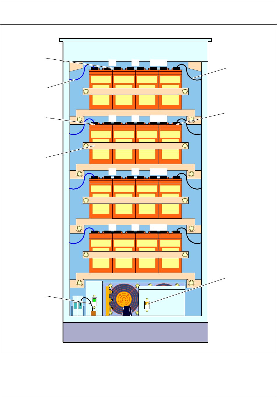
1.1.3 Additional equipment
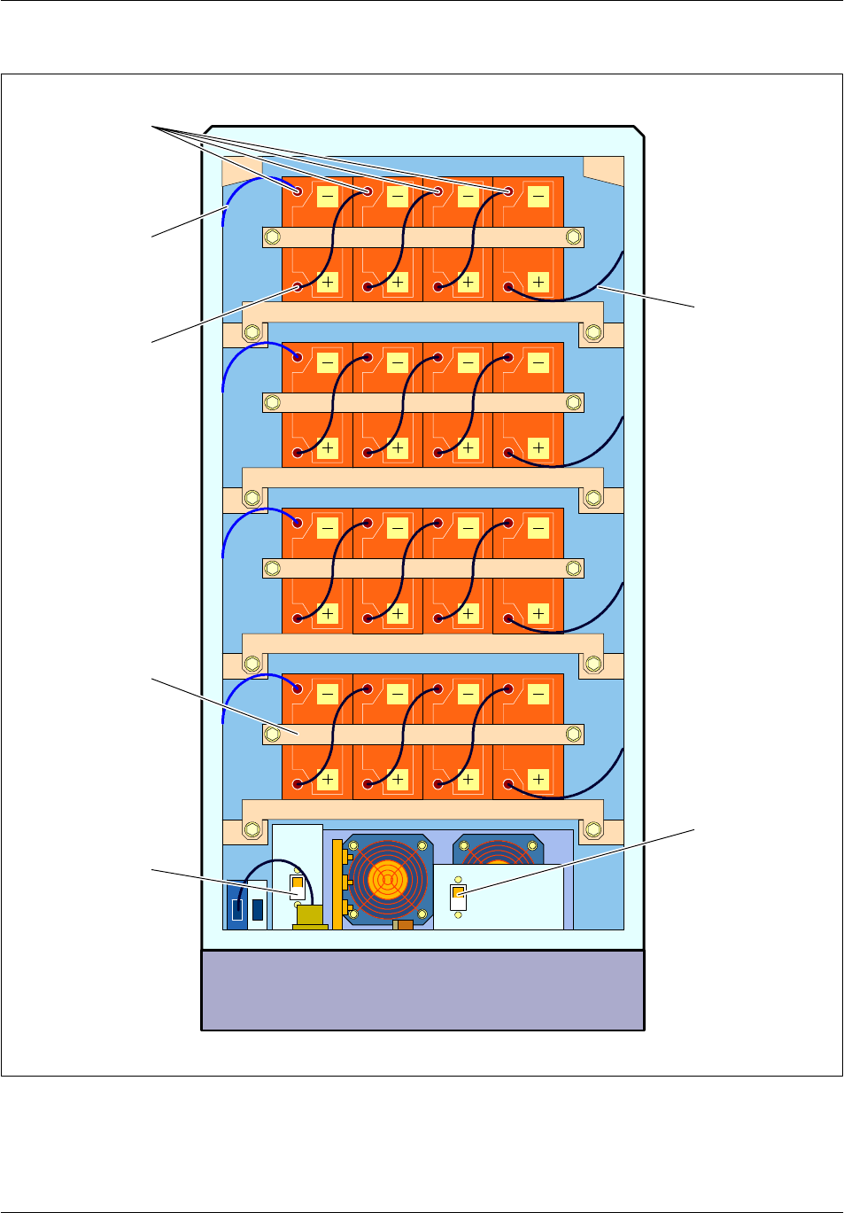
1.1.3.1 Battery cabinet
A cabinet, independent from the BTS cabinet, can be added to increase the power
autonomy of the BTS in case of a mains power failure. This cabinet may house one
of two possible types of battery. The batteries are arranged in four strings, each
containing four batteries (see Figure 1--3).
The internal batteries must first be disconnected before using these batteries.
These batteries autonomy depend on the configuration and the equipment of the
BTS, and can vary between 30 minutes and 14 hours.
The cabinet dimensions are described in NTP < 01 >.
Below the four battery strings is the Heating Ventilation Unit (HVU), consisting of
the following:
afan
a heating resistor
a controller
Cabinet descriptionNortel Networks Confidential 1--9
S12000 BTS Reference Manual
Copyright ©2002--2005 Nortel Networks
DC
box
Nut no. 2
Plinth
1
Nut no. 1
5
Clamp
1bis
DC breaker
2
AC box
62bis
3
AC breaker
73bis
484bis
Blue cable
Black cable
Figure 1--3 External battery cabinet of the S12000 Outdoor BTS (SBS 60 batteries)
Cabinet description Nortel Networks Confidential
1--10
PE/DCL/DD/0142
411--9001--142 Standard 15.102/EN May 2005 Copyright ©2002--2005 Nortel Networks
DC
box
Plinth
dc breaker
AC box
ac breaker
11bis5
22bis6
33bis7
44bis8
Strap
Black cable
Blue cable
Lug no. 2
Clamp
Lug no. 1
Figure 1--4 External battery cabinet of the S12000 Outdoor BTS (SBS C11 batteries)

Cabinet descriptionNortel Networks Confidential 1--11
S12000 BTS Reference Manual
Copyright ©2002--2005 Nortel Networks
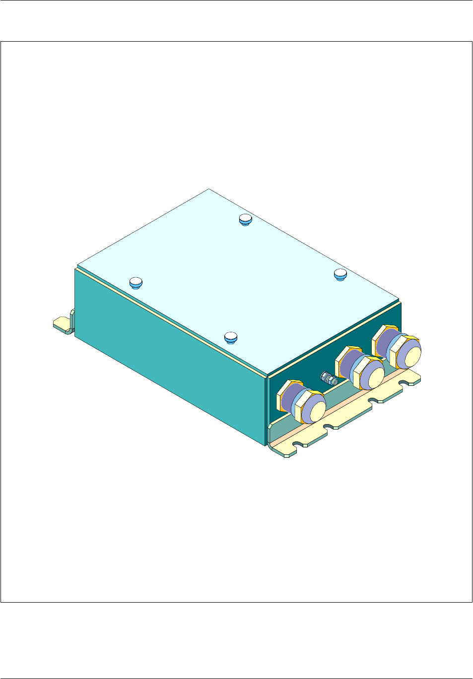
1.1.3.2 PCM connection box (S12000 Outdoor BTS option for GSM 850/1900)
This box is available as an option to protect two PCM links. An upgraded kit allows
the protection of up to six PCM links.
The PCM connection box is waterproof and can be put either in the BTS plinth or
on--site outside the BTS (see Figure 1--6).
The box can be fitted as suitable to the customer.
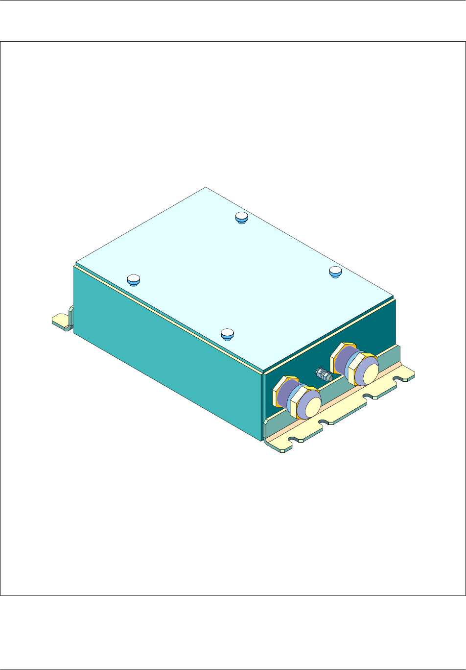
1.1.3.3 --48 V dc connection box (S12000 Outdoor BTS option for GSM 850/1900)
This box is available as an option to provide an external --48 V plug on--site.
The --48 V connection box is waterproof and can be put either in the BTS plinth or
on--site outside the BTS (see Figure 1--7).
The box can be fitted as suitable to the customer.
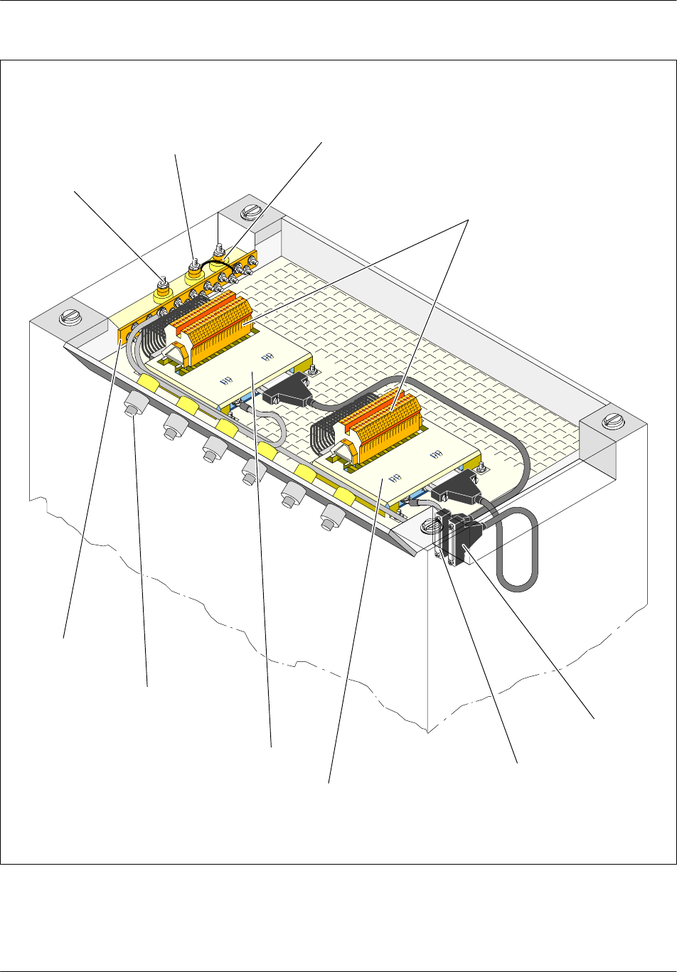
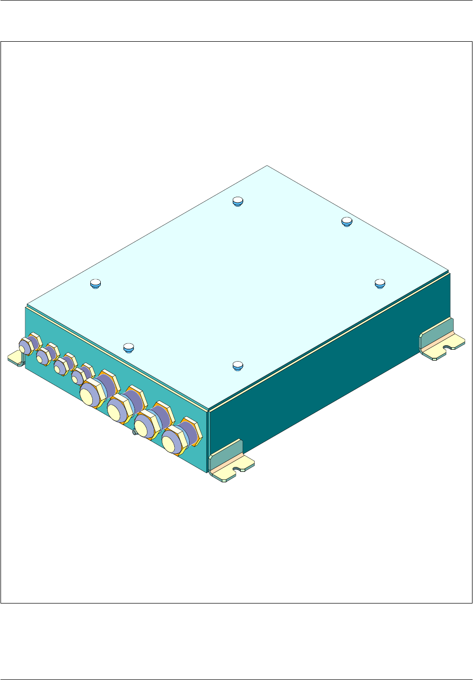
1.1.3.4 External alarm connection box (GSM 850/1900)
This box exists in two versions:
The outdoor version includes one or two ALPRO boards and the related primary
protection modules. It protects up to 16 external alarms (8 per ALPRO board)
and four remote controls (two per ALPRO board).
The external alarms connection box is waterproof and can be put either in the BTS
plinth or on--site outside the BTS (see Figure 1--8).
The indoor version includes one ALPRO board, which protects up to 8 external
alarms and two remote controls. Two indoor version boxes can be put on the top
of the S12000 indoor BTS (see Figure 1--5).
The box can be fitted as suitable to the customer.
Cabinet description Nortel Networks Confidential
1--12
PE/DCL/DD/0142
411--9001--142 Standard 15.102/EN May 2005 Copyright ©2002--2005 Nortel Networks
--48V
0V
ALPRO 0
ALPRO 1
Equipotentiality
stud
ALPRO 1
connector
RF connector
ALPRO 0
connector
Terminal blocks
Ground
bar
Figure 1--5 S12000 Indoor BTS: Cabinet top
Cabinet descriptionNortel Networks Confidential 1--13
S12000 BTS Reference Manual
Copyright ©2002--2005 Nortel Networks
Figure 1--6 S12000 Outdoor BTS: PCM connection box
Cabinet description Nortel Networks Confidential
1--14
PE/DCL/DD/0142
411--9001--142 Standard 15.102/EN May 2005 Copyright ©2002--2005 Nortel Networks
Figure 1--7 S12000 Outdoor BTS: --48 V connection box
Cabinet descriptionNortel Networks Confidential 1--15
S12000 BTS Reference Manual
Copyright ©2002--2005 Nortel Networks
Figure 1--8 External alarm connection box

Cabinet description Nortel Networks Confidential
1--16
PE/DCL/DD/0142
411--9001--142 Standard 15.102/EN May 2005 Copyright ©2002--2005 Nortel Networks
1.2 Power supply
1.2.1 S12000 Outdoor BTS
The power system supplies 48 V DC power to the modules in the cabinet from the
main power supply. Two solutions have been implemented to power supply
modules of S12000 Outdoor BTS (either one or the other, but never both together).
The first system is PCU based system
The second system is DCU based system: GSM Integrated power system
The PCU based system is implemented only in the 1900/850 BTS at the beginning
of the S12000 life cycle. In a second time the DCU based system (GIPS) replaces
the first system and is generalized in all types of BTS. Most of the functions are
common to both system (PCU and DCU based).
1.2.1.1 General description
This description is applicable to both systems, PCU based and DCU based (GIPS).
The basic functions of the power system are the following:
It accepts AC power and converts it up to 4200 W (PCU based) or 4760W (DCU
based) of DC power for the DC loads of the base station.
It provides an optional redundancy of DC power.
it provides separate controlled and overload protected DC outputs for each of the
DC loads.
It supports the charging and discharging of batteries that provide operational
power when the AC input is not available.
It monitors the state of the power system and reports the status to the host base
stations (alarms to RECAL board).
1.2.1.2 AC Distribution functions
3 types of AC power supply are supported:
mono phased (only supported by GIPS)
tri phased (only supported by GIPS)
split phase (supported by GIPS and PCU based system)
The AC distribution provides:
surge suppression
a system level circuit breaker for rectifiers power on/off and overload protection
a circuit breaker for DACS power on/off and overload protection
EMI filtering

Cabinet descriptionNortel Networks Confidential 1--17
S12000 BTS Reference Manual
Copyright ©2002--2005 Nortel Networks
1.2.1.3 User plug
The user plug is always available in the PCU based system (US plug type only), but
is optional for the GIPS.
1.2.1.4 Rectifier modules
The rectifiers convert input AC power into DC power for the DC loads within the
base station. The nominal output voltage is --54.6Vdc. The DC control system varies
the output voltage from --40Vdc to --58.3Vdc in order to manage the charging of an
attached battery string.
PCU based system receives both 600W or 680W rectifiers, but for 680W rectifier
use, the output power is limited to 600W.
DCU based system (GIPS) can only receive 680W rectifiers. A mechanical way
prevents 600W rectifier insertion.
Up to seven rectifiers (6+1 for redundancy) are housed in a rectifier shelf. Their
outputs are connected in parallel through the shelf back plane.
1.2.1.5 Batteries
There are two types of battery units:
internal batteries mounted on the top of the cabinet, which consist of four 12 V dc
batteries in series (one string)
external batteries located in the external battery cabinet, and configured in a
maximum of four strings. Each string consists of four 12V dc batteries in series,
the four strings being connected in parallel.
Sealed lead batteries are used.

Cabinet description Nortel Networks Confidential
1--18
PE/DCL/DD/0142
411--9001--142 Standard 15.102/EN May 2005 Copyright ©2002--2005 Nortel Networks
1.2.1.6 DC Distribution and control functions
The main function consists in the interconnection of the rectifiers set to the modules
of the BTS and to the batteries.
DC distribution
Both power systems provide 4 outputs to the different S12000 modules:
PA: DC distribution to the power amplifiers set
DRX: DC distribution to the DRX set
BCF: DC distribution to the basic functions of the BTS (CBCF, RECAL and the
user rack)
DACS: DC distribution to the cooling unit
It generates a disconnection of its four load outputs depending on :
the batteries output voltage level
the internal temperature of the cabinet
Cabinet descriptionNortel Networks Confidential 1--19
S12000 BTS Reference Manual
Copyright ©2002--2005 Nortel Networks
Fuse 10A
Fuse 10A
Fuse 10A
Fuse 10A
Fuse 2A
Fuse 2A
Fuse 10A
Fuse 1A
Fuse 4A
PCU/DCU
CBCF
DRX--ICOA CBCF compartmentPA -- I C O D R X -- I C O B
RECAL
80A
breaker
User
15A
breaker
15A
breaker
10A breaker
(PCU)
15A breaker
(DCU)
(Time delay)
90A
breaker
(*)
Internal
batteries
6
DRX
6
DRX
Climatic
system 2F--type
converters
12 power
amplifiers
Legend:
PA--ICO: Power Amplifier interconnection
DRX--ICO: DRX interconnection
Note: (*) The 90A breaker is used either for the internal battery or the external battery.
ac input
ac/dc
rectifiers
Figure 1--9 S12000 Outdoor BTS: dc power supply diagram

Cabinet description Nortel Networks Confidential
1--20
PE/DCL/DD/0142
411--9001--142 Standard 15.102/EN May 2005 Copyright ©2002--2005 Nortel Networks
Batteries management
When the power system stops supplying DC voltage, the batteries are the only
possible DC power supply.
The power system allows the cabinet to run on either internal or external batteries
(connection of the internal or external batteries is carried out manually, and it is not
possible to connect both types simultaneously). Two operating options are possible.
Option 1 (for PCU based system only):
•
If AC power is available, the power system powers all the outputs and, if
necessary, supplies power to the batteries (charging phase).
•
If the power system does not supply any power, the internal or external
batteries energize BCF and DACS outputs (discharging phase).
Option 2 (for PCU based system and GIPS):
•
If AC power is available, the power system powers all the outputs and, if
necessary, supplies power to the batteries (charging phase).
•
If the power system does not supply any power, the internal or external
batteries energize all the outputs (discharging phase).
During the discharging phases the battery output voltage decreases over time.
So, when the battery output voltage reaches LVD45 (--45V +/--1%), the power
system cuts off power supply to the boards in the cabinet that are connected to PA
and DRX outputs. An alarm is generated.
If the battery output voltage continues to decrease and reaches LVD42 (--42V
+/--1%), the power system cuts off power supply to the boards in the cabinet that
are connected to BCF and DACS outputs.
If the rectifiers recover power supply, the batteries are charging. When voltage is
equal to 50.6V +/-- 0.5%, the power system reconnects the cabinet boards with its
four outputs.
The power system receives an analog signal from a temperature probe located on
the batteries (internal or external) and sends a signal to the rectifiers to adjust the
rectifier output voltage inversely to battery temperature (floating voltage).
Alarm monitoring
The following alarms are provided to the RECAL board by the power system:
Load1 threshold (LVD45)
PCU protective devices (PA & DRX DC Breaker)
Battery on discharge
DC fault

Cabinet descriptionNortel Networks Confidential 1--21
S12000 BTS Reference Manual
Copyright ©2002--2005 Nortel Networks
AC fault
Over temperature
Cabinet extreme ambient temperature management
A signal (CEATS1) is provided by two ambient temperature probes (one is located
at the top of the cabinet, the other at the bottom) to the system power.
When activated, this signal causes the disconnection of all outputs connected to the
rectifiers and to the batteries
1.2.1.7 PCU based power system description
The PCU based power system is composed of the following parts:
an AC Main module
a Power Control Unit (PCU)
a set of up to seven rectifier units
a set of batteries
AC main
It provides the AC distribution functions.
It is made of an AC Main box with:
main power supply connections (split phase only)
a surge protection
an EMI filter
a user plug (US plug type only)
a main breaker, a DACS breaker, a rectifier breaker and an AC plug breaker

Cabinet description Nortel Networks Confidential
1--22
PE/DCL/DD/0142
411--9001--142 Standard 15.102/EN May 2005 Copyright ©2002--2005 Nortel Networks
PCU (Power Control Unit)
It provides the DC distribution and control functions.
It includes the PA breaker, the FAN breaker (DACS), the DRX breaker and the BCF
breaker. The batteries breaker is mounted on an external front panel.
The PCU is located in the rectifier shelf. It is an integral part of this sub--rack and
is not a Field Replaceable Unit (FRU).
Rectifier modules
PCU based system can receive both 600W or 680W rectifiers, but in case of 680W
rectifier use, the output power is automatically limited to 600W.
The rectifier shelf accepts up to seven rectifiers providing up to 4200W without
redundancy or 3600W with redundancy.
Cabinet descriptionNortel Networks Confidential 1--23
S12000 BTS Reference Manual
Copyright ©2002--2005 Nortel Networks
Climatic system circuit breaker
(15A)
Main circuit breaker (50A)
Two electrical outlets with
incorporated differential (5 mA)
Rectifier circuit breaker (35A)
ac voltage to the rectifiers
Ground
ac lightning protector
Fuse for the 15A electrical outlets
(F02, 250V, time delay)
Alarm return to the RECAL
board
ac voltage to the climatic system
and the heaters
.
Figure 1--10 Split single phase ac box
Cabinet description Nortel Networks Confidential
1--24
PE/DCL/DD/0142
411--9001--142 Standard 15.102/EN May 2005 Copyright ©2002--2005 Nortel Networks
2
2
3
2
2
2
Climatic
system circuit
breaker
Alarm return to
RECAL board
Two electrical outlets
with incorporated
differential cut--outs (5mA)
Main circuit
breaker
Rectifier
circuit breaker
ac voltage
to climatic
system and
heaters
ac voltage to
rectifiers
Filter neutral
Filter phase 1 Lightning
protector
ac power supply
15A fuse for electrical outlets
Ground
Ground
Filter phase 2
Figure 1--11 Side view of inside of split single--phase ac box

Cabinet descriptionNortel Networks Confidential 1--25
S12000 BTS Reference Manual
Copyright ©2002--2005 Nortel Networks
1.2.1.8 DCU based power sytem description (GIPS)
The DCU based power system is composed of the following parts:
an AC Box module and an optional User AC Plug kit
an AC Distribution Unit (ADU)
a DC Distribution and Control Unit (DCU)
a set of up to seven rectifier units
a set of batteries
AC BOX/GIPS and user ac plug
It includes only main power supply connection.
The GIPS based power system operates from 3 types of AC power networks
depending on the AC Box internal interconnection:
single phased network
three phased network
split phased network
An optional User AC plug kit is connected to the AC Box. Four plug types are
available:
european type E
european type F
UK
US
The user plug kit includes a breaker (differential breaker for European models and
fuse for North American models).
ADU (AC Distribution Unit)
It provides the AC distribution functions.
The ADU is located in the rectifier shelf and is a Field Replaceable Unit (FRU).
It includes:
a surge protection
EMI filters
a DACS breaker, rectifier breakers
DCU (DC Distribution and Control Unit)
It provides the DC distribution and control functions.

Cabinet description Nortel Networks Confidential
1--26
PE/DCL/DD/0142
411--9001--142 Standard 15.102/EN May 2005 Copyright ©2002--2005 Nortel Networks
It includes the PA breaker, the DACS breaker, the DRX breaker and the BCF
breaker. The batteries breaker is mounted on an external front panel.
The DCU is located in the rectifier shelf. It is an integral part of this sub--rack and
is not a Field Replaceable Unit (FRU).
Rectifier modules
DCU based system (GIPS) receives only 680W rectifiers. A mechanical way
prevents 600W rectifier insertion.
The rectifier shelf accepts up to seven rectifiers providing up to 4760 W without
redundancy or 4080 W with redundancy.
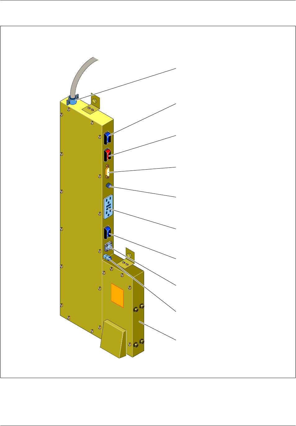
Cabinet descriptionNortel Networks Confidential 1--27
S12000 BTS Reference Manual
Copyright ©2002--2005 Nortel Networks
US AC plug
5mA/120Vac
Indicator fuse 15A
AC voltage to
the power system
compartment
AC input
terminal block
Figure 1--12 AC box/GIPS with US type user AC plug BTS
Cabinet description Nortel Networks Confidential
1--28
PE/DCL/DD/0142
411--9001--142 Standard 15.102/EN May 2005 Copyright ©2002--2005 Nortel Networks
European AC
plug 230Vac
Differential circuit
breaker 6A/30mA
AC voltage to
the power system
compartment
AC input
terminal block
Figure 1--13 AC box/GIPS with E, F, UK type user AC plug
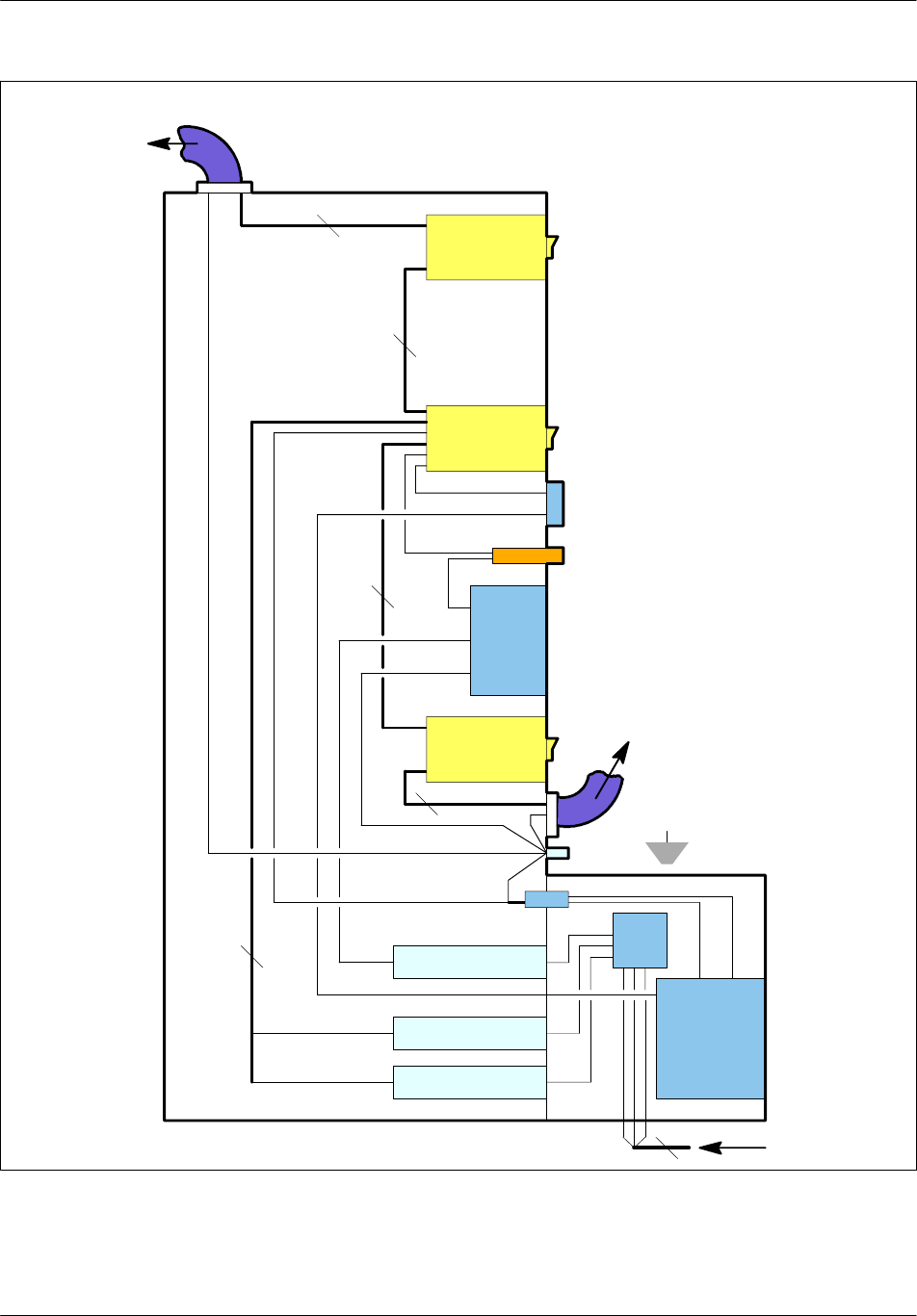
Cabinet descriptionNortel Networks Confidential 1--29
S12000 BTS Reference Manual
Copyright ©2002--2005 Nortel Networks
AC BOX
Mains
Ground
to GIPS
AC plug kit
(optional)
Electrical outlet
Fault
Interrupter
(differential breaker)
Figure 1--14 Side view of inside of AC box/GIPS

Cabinet description Nortel Networks Confidential
1--30
PE/DCL/DD/0142
411--9001--142 Standard 15.102/EN May 2005 Copyright ©2002--2005 Nortel Networks
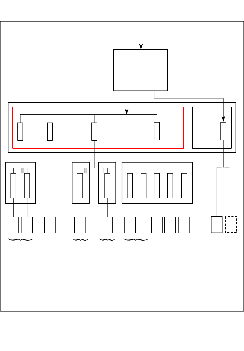
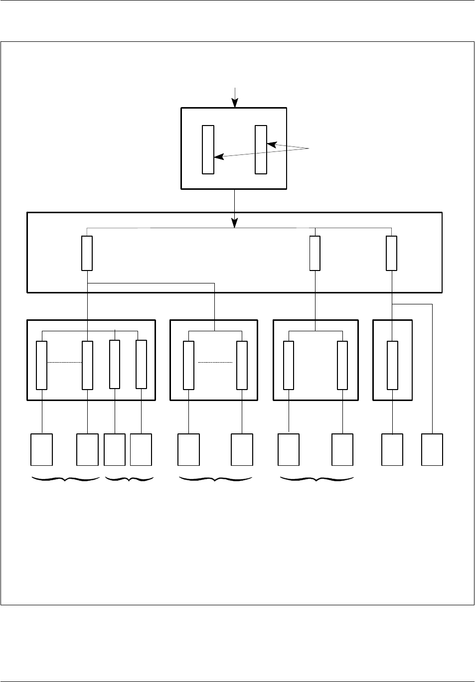
1.2.2 S12000 Indoor BTS
Figure 1--15 shows the dc power supply distribution. Two filters protect the dc
distribution input against conducted emission. The dc power supply feeds the dc
compartment where four outputs come out to the following equipment groups:
the twelve power amplifiers and the two F--type converters, through the power
amplifier interconnection module
the two fans, through the fan interconnection module
the twelve DRXs, through the DRX interconnection module
the CBCF
the RECAL board
The dc compartment houses four breakers to disconnect the powering of these
equipment groups.
The dc distribution for each group uses three cables:
+0 V dc
-- 4 8 V d c
ground
Cabinet descriptionNortel Networks Confidential 1--31
S12000 BTS Reference Manual
Copyright ©2002--2005 Nortel Networks
ac input
dc compartment
100A
breaker
10A
breaker
12 power
amplifiers
2F--type
converters 12 DRXs
Legend :
PA--ICO : Power Amplifier interconnection
FAN--ICO : Fan interconnection
DRX--ICO : DRX interconnection
EMI filters
PA/DRX
FANS RECAL
CBCF
5A
breaker
CBCF
2 fans
CBCF
RECAL
PA_ICO FAN_ICO
DRX_ICO
Fuse 10A
Fuse 10A
Fuse 10A
Fuse 2A
Fuse 2A
Fuse
Fuse
Fuse 4A
Fuse 10A
Figure 1--15 S12000 Indoor BTS: dc power supply diagram

Cabinet description Nortel Networks Confidential
1--32
PE/DCL/DD/0142
411--9001--142 Standard 15.102/EN May 2005 Copyright ©2002--2005 Nortel Networks
1.3 Climatic System
1.3.1 S12000 Outdoor BTS
The climatic system controls the inside temperature of the cabinet. It is located in
the top compartment of the cabinet. The climatic system consists of a Direct
Ambient Cooling System (DACS).
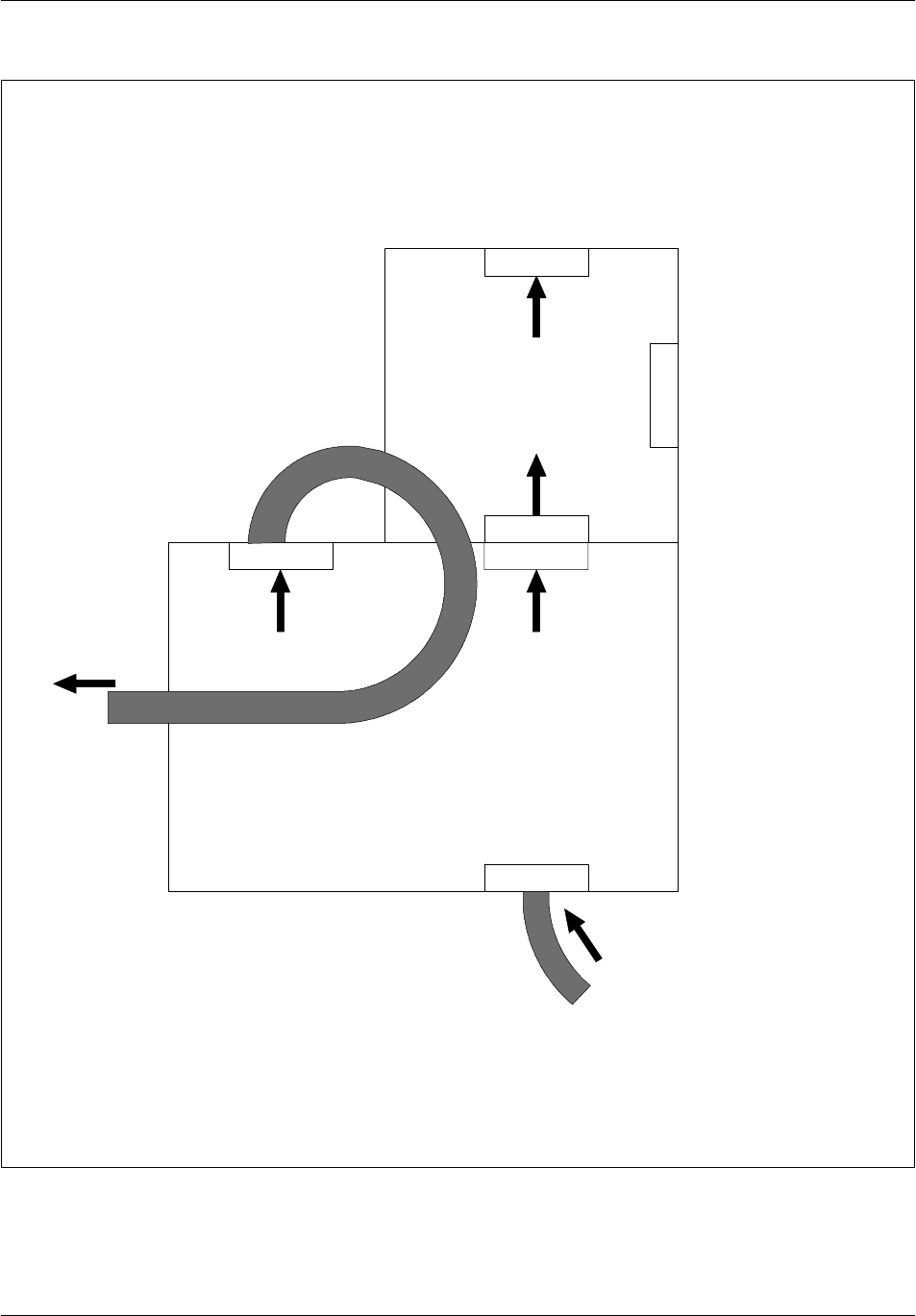
The operating principle is the following:
An air damper opens to admit external air (incoming air is filtered) and controls
the inner cabinet environment by mixing appropriate amounts of outside and
recirculated air.
Twin blowers drive air down the rear duct and into the equipment enclosure via
slots at the rear. Returned air to the cooling system is routed through two sets of
holes in the base, with excess air being rejected from vents located on either side
of the system.
The internal temperature control is achieved by a high quality thermistor that has
an accuracy of ±0.2°C (0.36_F) between 0°C(32_F) and 70°C (158_F). This device
is located in the left hand exit duct above a hole on the duct side; the hole ensures
that the thermistor is constantly in a moving air stream, regardless of damper
position. The operational mode of the Cooling system is solely dictated by the
information provided by the thermistor.
There are four operational modes:
Low temperature --40°C(--56°F)<Tcab<15°C(59°F)
The heater is powered on, the damper is closed to the outside and air is
recirculated via the holes in the base of the cooling system.
Medium temperature 15°C(59°F)<Tcab<40°C (104°F)
The heater is switched off, the damper remains closed and further heating of the
equipment enclosure is achieved solely by the internal equipment loading.
Normal temperature Tcab = 40°C (104°F)
The damper position is controlled automatically by the modulating motor,
mixing appropriate amounts of recirculated and external air to maintain a
constant temperature. Excess air is rejected from the cooling system from vents
at either side of the cooling system.
High temperature Tcab > 40°C (104°F)
Although the damper is fully open, the cooling system is unable to keep the
cabinet temperature to 40°C (104°F) which now rises in sympathy with the
external temperature. At an outside temperature of 50°C (122°F), the internal
cabinet will rise to a nominal 60°C (140°F) under fully loaded conditions.
The cooling system is supplied with:

Cabinet descriptionNortel Networks Confidential 1--33
S12000 BTS Reference Manual
Copyright ©2002--2005 Nortel Networks
two hard alarm outputs:
•
The first alarm output signals a fault on the cooling system.
•
The second alarm output indicates a maintenance requirement for the filter.
three alarm LEDs for on--site fault diagnostics:
•
The red LED indicates a critical alarm for fan failure.
•
The yellow LED indicates a critical alarm for heater circuit failure.
•
The green LED indicates a maintenance alarm for clogged filter.
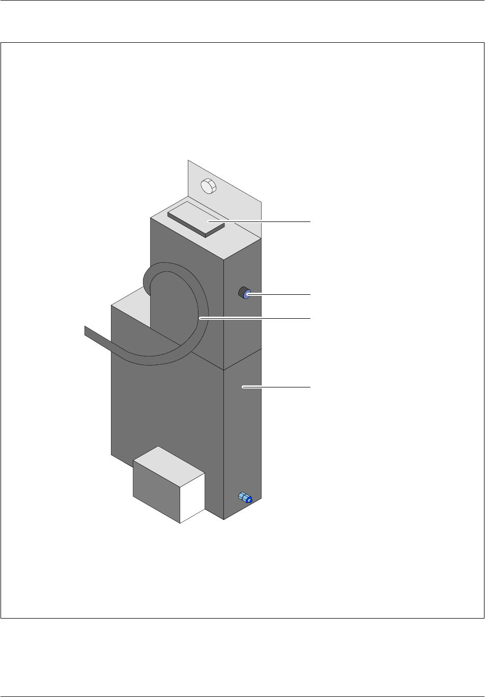
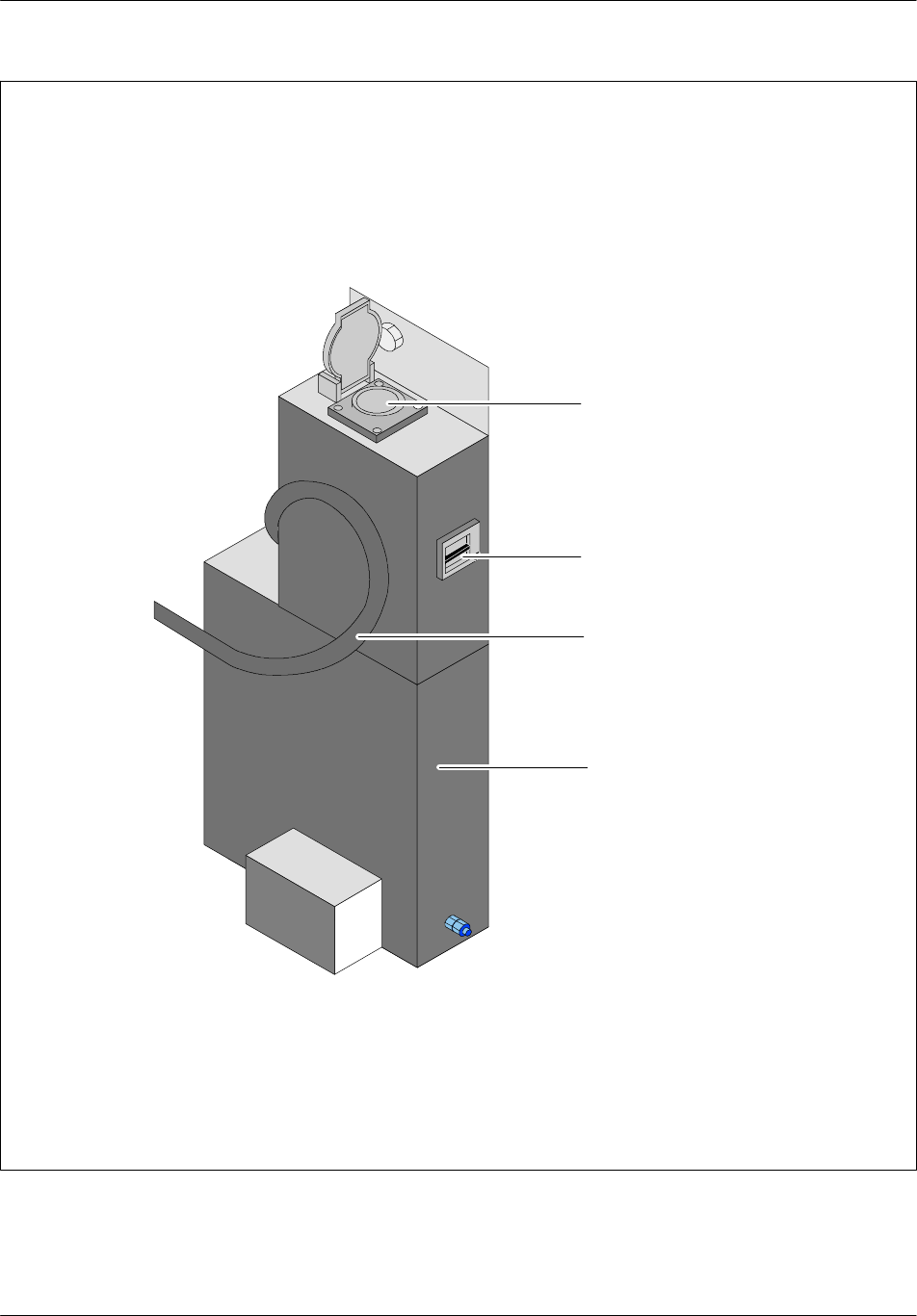
On the top of the cooling system, there is a window in the lid which allows the
user to view the LEDs. The LEDs are normally lit when healthy and off alarm.
The cooling system is dc powered which allows internal or external battery
back--up. The dc power consumption of the cooling system is 400--450 W. The cold
start--up performance of the unit is controlled by an inbuilt ac to dc converter (for
operation of the fans) and by a 2.5 kW heating element.
1.3.2 S12000 Indoor BTS
The Internal Cooling System (ICS) controls the inside temperature of the cabinet.
It is located in the lowest compartment of the cabinet. The ICS consists of a rack
which contains:
two blowers
a filter
a converter
a control board
a front panel which contains three LEDs:
•
FAN1/CONV, which is lit green when there is no failure on the first fan or on
the converter.
•
FAN2, which is lit green when there is no failure on the second fan.
•
FILTER, which is lit green when the filter is not clogged.

Cabinet description Nortel Networks Confidential
1--34
PE/DCL/DD/0142
411--9001--142 Standard 15.102/EN May 2005 Copyright ©2002--2005 Nortel Networks
1.4 Plinth
The S12000 Outdoor BTS cabinet can be installed on a plinth allowing for cable
passage. The plinth characteristics are described in NTP < 01 >.
The plinth may contain the external alarm connection box, the PCM connection box
and the --48 V dc connection box.
These boxes are screwed into the inside of the plinth.
The S8000 plinth can be used for the S12000 Outdoor BTS.

Cabinet descriptionNortel Networks Confidential 1--35
S12000 BTS Reference Manual
Copyright ©2002--2005 Nortel Networks
1.5 Physical characteristics
1.5.1 S12000 Outdoor BTS
Physical characteristics
RefertoNTP<01>.
Operating temperature
To operate correctly, the BTS requires a temperature greater than --40°C(--56°F)
and less than +50°C (+122°F).
Autonomy of the internal battery
The internal battery is an optional equipment located in the top compartment. The
battery backup time depends on the configuration and the BTS equipment, and can
vary from 30 minutes to a few hours.
1.5.2 S12000 Indoor BTS
The S12000 Indoor BTS cabinet can be wall--mounted or put on the floor.
Physical characteristics
RefertoNTP<01>.
Operating temperature
When the base cabinet is turned on, the external ambient air temperature must be
between 0°C(32°F) and 45°C(113°F).
Once in operation, the base cabinet requires an external ambient air temperature
above --5°C(23°F) and below 45°C(113°F).
Cabinet description Nortel Networks Confidential
1--36
PE/DCL/DD/0142
411--9001--142 Standard 15.102/EN May 2005 Copyright ©2002--2005 Nortel Networks
1.6 Product names
A BTS contains one or more cabinets and the associated supplies (cables, covers,
endings, etc.).
BTS products are identified by six items:
Sectorization Number of X = Number of sectors
Number of cabinets
Frequency DCC number of DCC or
DSC
Cabinet type
PCM type
option and impedance
Number of TRXs in the first sector Number of TRXs in the second sector
Number of TRXs in the Xth sector
TX type, power, radio
test, encryption
Number of DTI or PCMI
boards
Letter for future use
BBB FF UUU VSXX....Xzz PP/PP QRA
Type of coupling system
Example: BBB = OUD (S12000 Outdoor BTS)
BBB = IND (S12000 Indoor BTS)

Cabinet descriptionNortel Networks Confidential 1--37
S12000 BTS Reference Manual
Copyright ©2002--2005 Nortel Networks
PAGE INTENTIONALLY LEFT BLANK

Board descriptionNortel Networks Confidential 2--1
S12000 BTS Reference Manual
Copyright ©2002--2005 Nortel Networks
2 BOARD DESCRIPTION
2.1 Power Amplifier (PA)
The Power Amplifier (PA) amplifies the GUMS signal from a low--level
transmission unit and sends it to the transmission coupler.
HePA is compatible with e--DRX (all frequencies) and DRX ND3 (900) and with
the indoor and outdoor S8000 and S12000 cabinets. The cabinet can contain a
maximum of 12 HePAs.
Three types of PA are available : PA, ePA and HePA (High Power Amplifier). The
HePA can be used mixed with PA and ePA.
PA and ePA are class 5 amplifiers, that is, they can provide power of between 20 W
and 40 W. Nominal power is 30 W.
HePA is the BTS Power Amplifier with transmit power up to 60 W in GMSK and
is Edge compatible.
HePA is compatible with S8000 CBCF and S12000 cabinets (indoor + outdoor) and
works with eDRX and DRX ND3. HePA is not compatible with DRX.
The HePA can be mixed with PA in step coupling configurations. It can be mixed
with (e)PA in a normal cell if its power is being configured with a value that is
compatible with (e)PA (lower than 30 Watt).
The range of value of the OMC parameter ”bsTxPwrMax” that sets the power of
the TRX, already permits to configure power up to 60 Watts.
The HePA is differentiated at the OMC from PA and ePA; in the same way the ePA
is differentiated from the PA.
It contains its own dc/dc converter and contains a microcontroller which allows it
to dialogue with the low--power transmission module. This function makes it
possible to move the power amplifier to the top of the tower if necessary.
2.1.1 Amplifier alarms
The power amplifier provides several alarms:
an overtemperature alarm, whose threshold is set in the PA
an overvoltage alarm, whose threshold is set in the PA
an alarm indicating that the PA output reflected power is exceeded
This alarm is triggered when the reflect power exceeds 6W.
an alarm dedicated to the DC/DC converter

Board description Nortel Networks Confidential
2--2
PE/DCL/DD/0142
411--9001--142 Standard 15.102/EN May 2005 Copyright ©2002--2005 Nortel Networks
a communication alarm
This alarm is triggered by a parity bit error or control byte error.
an input power alarm, whose threshold is set in the PA
The DRX must then reduce its output level (PA input level) to make the alarm
disappear
a consumed current alarm whose threshold is set in the PA
2.1.2 Power supply
The power amplifier receives a 48 V power supply from the cabinet. The converter
accepts an input voltage between 36 V and 57 V (nominally 48 V). It then provides
the regulated 24 V voltage needed for operation of the PA radio stages.
Maximum consumption is 220 Wfor PA, 200 Wfor ePA and 290 Wfor HePA 1900
MHz or 230 W for HePA 900 MHz. Actual consumptions are lower, with a typical
maximum of 170 W for ePAs, 230 W for HePA 1900 and 200 W for HePA 900.
S12000 indoor:
At low speed:
The HePA operates 12°C lower in S12000 than in S8000.
The HePA temperature rise is 4°C lower than specification in S12000 (+26°C
above ambient).
At high speed:
The HePA operates 17°C lower in S12000 than in S8000.
The HePA temperature rise is 9°C lower than specification in S12000 (+26°C
above ambient).
2.1.3 Connectors
The power amplifier connectors are located on the front panel.
Board descriptionNortel Networks Confidential 2--3
S12000 BTS Reference Manual
Copyright ©2002--2005 Nortel Networks
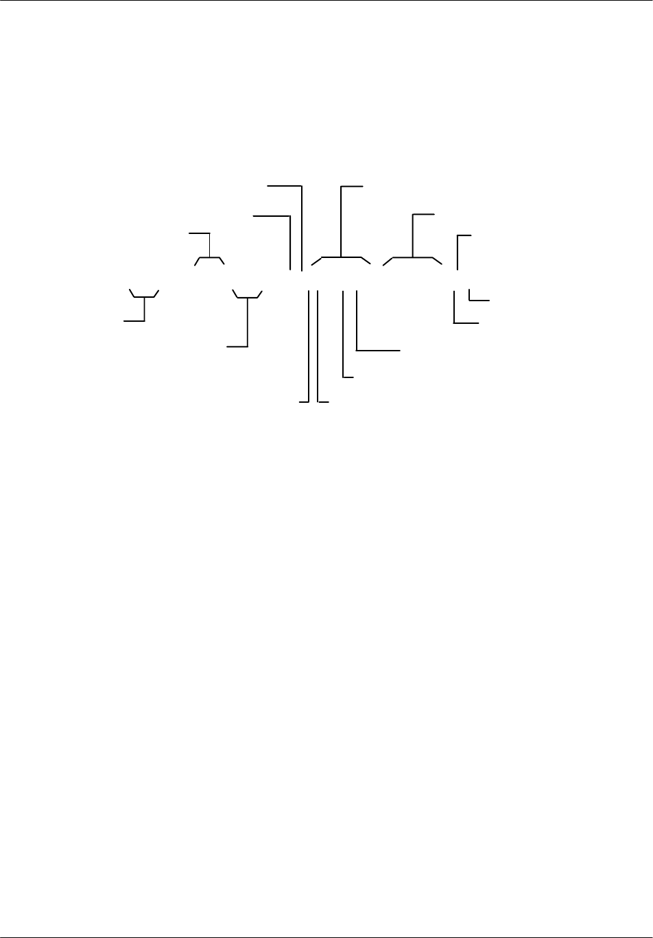
DATA I/O
POWER IN
RF OUT
RF SAMPLERF IN
FUSE
10A
Note: In the S12000 Indoor BTS, the front panel is inverted
compared to the figure presented
F1 Fuse
10A
250V time delay
Figure 2--1 S12000 BTS: Power Amplifier (type 1)
Board description Nortel Networks Confidential
2--4
PE/DCL/DD/0142
411--9001--142 Standard 15.102/EN May 2005 Copyright ©2002--2005 Nortel Networks
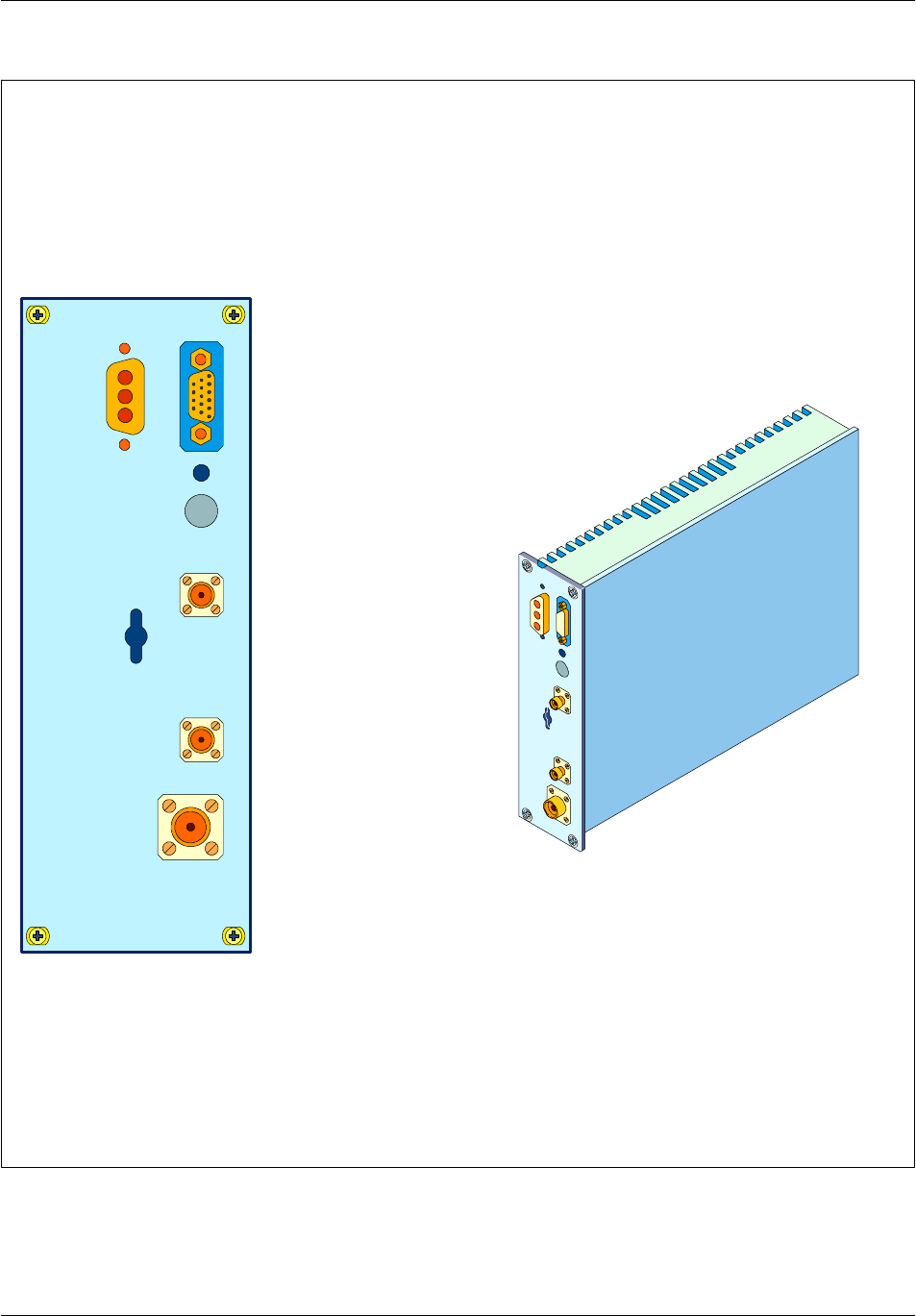
DATA I/O
POWER IN
RF OUT
RF IN
Note: In the S12000 Indoor BTS, the front panel is inverted
compared to the figure presented
Figure 2--2 S12000 BTS: Power Amplifier (type 2)

Board descriptionNortel Networks Confidential 2--5
S12000 BTS Reference Manual
Copyright ©2002--2005 Nortel Networks
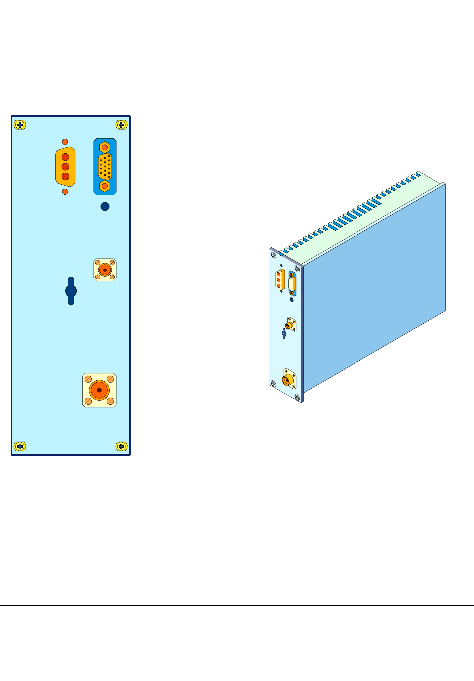
DATA I/O
POWER IN
RF OUT
RF IN
Note: In the S8000 Indoor BTS, the front panel is inverted
compared to the figure presented.
Figure 2--3 S12000 BTS: High Power Amplifier (HePA)

Board description Nortel Networks Confidential
2--6
PE/DCL/DD/0142
411--9001--142 Standard 15.102/EN May 2005 Copyright ©2002--2005 Nortel Networks
2.1.3.1 Radio connectors
There are three radio connectors:
The radio input connector, marked “RF IN”, is a female, SMA connector.
The radio output connector, marked “RF OUT”, is a female, N--type connector.
The test connector, marked “RF SAMPLE”, is a female, SMA connector.
According to to the PA type, this connector is optional.
2.1.3.2 Voltage supply connector
The --48 V supply of the PA is supplied through a male, three--pin connector. The
pin connections are as follows:
148 V (--)
2GND
30V
Table 2--1 Voltage supply connector

Board descriptionNortel Networks Confidential 2--7
S12000 BTS Reference Manual
Copyright ©2002--2005 Nortel Networks
2.1.3.3 Data connector
The data input/output connector is a 20--pin connector. The pin connections are as
follows:
1GND
2GND
3SYNC
4MEU_DATA_OUT
5Selection of PA operating mode
6SECT_SEL_0 (not used by the PA)
7MEU_DATA_IN
8Test point
9Test point
10 Test point
11 GND
12 GND
13 NSYNC
14 NMEU_DATA_OUT
15 Test point
16 SECT_SEL_1 (not used by the PA)
17 NMEU_DATA_IN
18 Test point
19 Test point
20 Test point
Table 2--2 Data connector

Board description Nortel Networks Confidential
2--8
PE/DCL/DD/0142
411--9001--142 Standard 15.102/EN May 2005 Copyright ©2002--2005 Nortel Networks
2.2 RECAL board
2.2.1 Functional description
The RECAL board is the alarm management unit used with the CBCF. The RECAL
collects external and internal alarm loops and alarms associated with OEM
equipment.
A slave of the CBCF, the RECAL board sends alarms to the CBCF over a Private
PCM link. The CBCF signals the BSC when there is an alarm.
There is one RECAL board per cabinet.
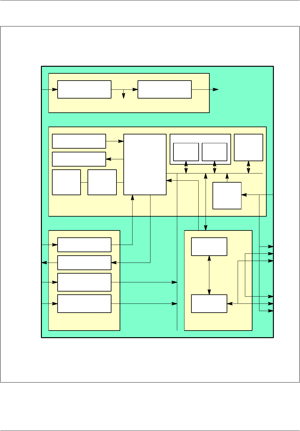
The following functional blocks of the RECAL board are shown in Figure 2--4:
Control unit
Alarms interface
Communication interface
Power supply
2.2.1.1 Alarm management
The RECAL board collects three types of alarms:
Internal alarms
Unprotected external alarms
Protected external alarms
Internal alarms
The RECAL board detects up to 56 internal alarms logical signals.
Internal alarms are wire loops that can only be opened or closed by dry contacts or
open collectors.
A closed loop forces a low logic level (less than 1.35 V) on the trigger output, which
indicates that there is no alarm. An open loop forces a high logic level (greater than
3.15 V) on the trigger output.
The CPU runs polling sequences to recognize the alarm state.
Board descriptionNortel Networks Confidential 2--9
S12000 BTS Reference Manual
Copyright ©2002--2005 Nortel Networks
48VDC/5VDC
Conversion
5VDC/12VDC
Isolated Conversion
+5Vdc +12VDC
isolated
Power supply
Reset logic
LEDs
Debug
PORT
Loopback
logic
CPU
io
io io
sci
@, data
/irq
Flash
EPROM SRAM
Memory Address
decoding
logic
Cabinet
reference
number
Control unit
A/D channels
Internal alarms
interface
Remote control
External alarms
interface
HDLC
controller
PCM
interface
SEL[4:7]
2PCMs
from/to
Cavities
2PCMs
from/to
CMCFs
48VDC
power supply
4 A/D inputs
4 remote
control outputs
88 internal
alarms
16 external
alarms
Alarms interface Communication
interface
Figure 2--4 RECAL board functional diagram

Board description Nortel Networks Confidential
2--10
PE/DCL/DD/0142
411--9001--142 Standard 15.102/EN May 2005 Copyright ©2002--2005 Nortel Networks
Unprotected external alarms
The RECAL board detects unprotected external alarms the same as the internal
alarms, which can be used inside the cabinet or within a few meters outside the
cabinet.
Protected external alarms
The RECAL board detects up to 16 protected external alarms. These alarms can be
used outside the cabinet by adding two ALPRO boards, which manage 8 alarms
each.
A closed loop forces a low logic level (0 mA) on the optocoupler collector,
indicating that there is no alarm. An open loop forces a high logic level (5 mA) on
the optocoupler collector, indicating that there is an alarm.
The operation is performed via the external remote commands (close/open relay)
accessible via the ALPRO box connected to the EXT. P. connector of the RECAL
board.
The EXT. P. (external protected alarm) connector provides pins ETC0A (pin17) and
ETC0B (pin18), both connected to an internal relay ETC0 within the RECAL board
(see Table 2--8).
2.2.1.2 Analog to digital inputs
The RECAL board reads four analog channels (voltage 0 to 5 V DC) that are
converted in digital signals by an eight--bits signal into a analog/digital converter.
2.2.1.3 Remote control outputs
Four remote control relay outputs are provided with a maximum current of 80 mA
and a maximum voltage of 72 V DC.
2.2.2 Physical description
This section describes the LEDs, connectors, and the electrical characteristics of the
RECAL board.
2.2.2.1 Front panel
The front panel of the RECAL board has the following:
One reset button
Three LEDs
Six connectors
The reset button allows a hard reset of the board.

Board descriptionNortel Networks Confidential 2--11
S12000 BTS Reference Manual
Copyright ©2002--2005 Nortel Networks
The front panel of the RECAL board is shown in Figure 2--5.
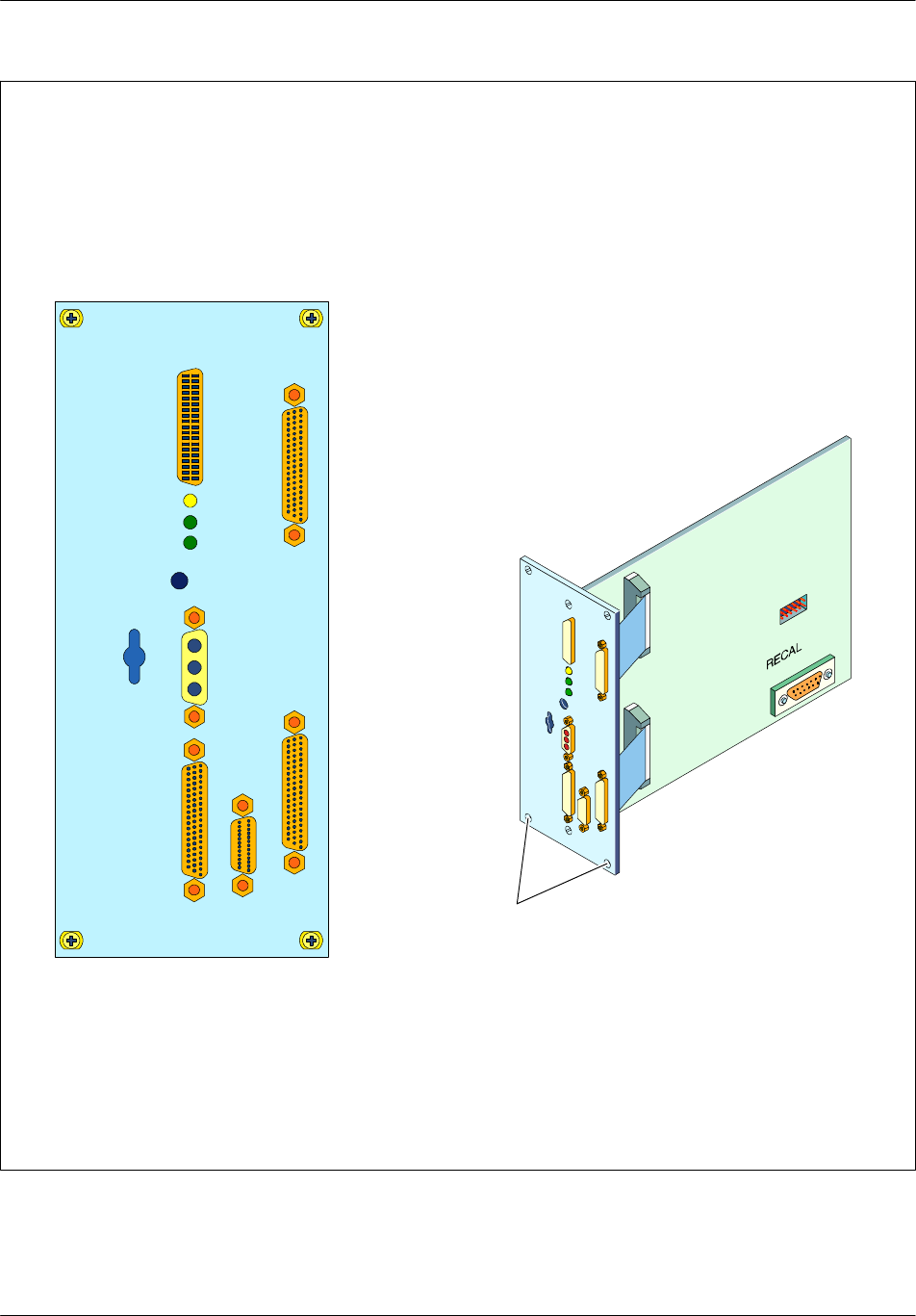
Board description Nortel Networks Confidential
2--12
PE/DCL/DD/0142
411--9001--142 Standard 15.102/EN May 2005 Copyright ©2002--2005 Nortel Networks
EXT. P.
INT.
PCM OUT
PWR
RESET
BIST
+5V
RDY
PCM
EXT. NP.
RECAL
Screws
Figure 2--5 RECAL board

Board descriptionNortel Networks Confidential 2--13
S12000 BTS Reference Manual
Copyright ©2002--2005 Nortel Networks
2.2.2.2 LEDs
There are three LEDs on the front panel of the RECAL board, described in
Table 2--3.
Type No. of
LEDs
Label
(color) Meaning (when lit)
Board state
indicators
1BIST (yellow) The built--in self--test is
running or is stopped with a
default result.
1+5 V (green) The power is on.
1RDY (green) The board is operating
normally.
Table 2--3 LEDs on the front panel of the RECAL board

Board description Nortel Networks Confidential
2--14
PE/DCL/DD/0142
411--9001--142 Standard 15.102/EN May 2005 Copyright ©2002--2005 Nortel Networks
2.2.2.3 Connectors
There are six connectors on the front panel of the RECAL board, which are wired
to corresponding connectors on left/right side of the board (see Figure 2--5)
Additionally, there are two connectors that are accessible only from inside the
board.
Access No. of
connectors Label Type Purpose
Front panel 1PCM SCSI 50--pin female PCM lines to and from the CBCF and
cabinet reference number. Wired to
the P4 connector soldered on the
inside of the board. The debug port
(P0) inside the board is connected to
the PCM connector.
1PWR Sub--D 3--pin male
Type 3W3
48 V DC Power supply input.
1PCM
Out
Sub--D 25--pin female PCM lines to and from cavities. Wired
to the P6 connector soldered on the
inside of the board.
1INT Sub--D high density
62--pin female
56 internal alarms (32 to 87). Wired
to the P3 connector soldered on the
inside of the board.
1EXT. P. Sub--D 50--pin female 16 external protected alarms and 4
remote control outputs. Wired to the
P5 connector soldered on the inside
of the board.
1EXT.NP. Sub--D 50--pin female 32 internal alarms (0 to 31) and 4
analog to digital conversion channels.
Wired to the P2 connector soldered
on the inside of the board.
Inside the
board
1P0 Sub--D 9--pin male Debugging port (the connector is not
equipped).
1P1 10--pin male EPLD Programming port, used in the
factory to program the EPLD.
Table 2--4 RECAL board connectors

Board descriptionNortel Networks Confidential 2--15
S12000 BTS Reference Manual
Copyright ©2002--2005 Nortel Networks
Pin connections
The pin connections and their significance are identified in Table 2--5 to
Table 2--12.
Pin no. Purpose Pin no. Purpose Pin no. Purpose
50 49 TXDBG
47 RXDBG 48 PCBUG0 46 GND
44 45 43 GND
41 GND 42 GND 40 GND
38 NSEL6 39 NSEL7 37 NSEL5
35 GND 36 NSEL4 34 NMICR1
32 NH4M 33 NMICR0 31 NMICE0
29 NMICE1 30 NSY 28
26 27 25
23 24 22
20 21 19
17 GND 18 GND 16 GND
14 SEL7 15 GND 13 SEL6
11 SEL4 12 SEL5 10 GND
8MICR0 9MICR1 7H4M
5SY 6MICE0 4MICE1
2 3 1
Legend:
H4M 4MHzclock
SY Frame synchronization signal
MICE Transmit PCM line
MICR Receive PCM line
GND Ground
SEL/NSEL Cabinet number selection
Table 2--5 PCM pin connections

Board description Nortel Networks Confidential
2--16
PE/DCL/DD/0142
411--9001--142 Standard 15.102/EN May 2005 Copyright ©2002--2005 Nortel Networks
Pin no. Purpose Pin no. Purpose
13 GND
25 NSY 12 SY
24 NH4M 11 H4M
23 NMICR1 10 MICR1
22 NMICR0 9MICR0
21 NMICE1 8MICE1
20 NMICE0 7MICE0
19 GND 6GND
18 GND 5GND
17 NSEL7 4SEL7
16 NSEL6 3SEL6
15 NSEL5 2SEL5
14 NSEL4 1SEL4
Legend:
H4M 4MHzclock
SY Frame synchronization signal
MICE Transmit PCM line
MICR Receive PCM line
GND Ground
Table 2--6 PCM--out pin connections

Board descriptionNortel Networks Confidential 2--17
S12000 BTS Reference Manual
Copyright ©2002--2005 Nortel Networks
Pin no. Purpose Pin no. Purpose Pin no. Purpose
42 GND 21 DALI87
62 DALI86 41 DALI85 20 DALI84
61 DALI83 40 DALI82 19 DALI81
60 DALI80 39 DALI79 18 GND
59 DALI78 38 DALI77 17 DALI76
58 DALI75 37 DALI74 16 DALI73
57 DALI72 36 DALI71 15 DALI70
56 DALI69 35 DALI68 14 DALI67
55 DALI66 34 GND 13 DALI65
54 DALI64 33 DALI63 12 DALI62
53 DALI61 32 DALI60 11 DALI59
52 DALI58 31 DALI57 10 DALI56
51 DALI55 30 DALI54 9DALI53
50 GND 29 DALI52 8DALI51
49 DALI50 28 DALI49 7DALI48
48 DALI47 27 DALI46 6DALI45
47 DALI44 26 DALI43 5DALI42
46 DALI41 25 GND 4DALI40
45 DALI39 24 DALI138 3DALI37
44 DALI36 23 DALI135 2DALI34
43 DALI33 22 GND 1DALI32
Legend:
DALI Internal Alarm Detection
GND Ground
Table 2--7 Internal pin connections

Board description Nortel Networks Confidential
2--18
PE/DCL/DD/0142
411--9001--142 Standard 15.102/EN May 2005 Copyright ©2002--2005 Nortel Networks
Pin
no. Purpose Pin
no. Purpose Pin
no. Purpose
50 33 MLC 17
49 ETC1B_ALPRO1 32 MLC 16 ETC1A_ALPRO1
48 +5V 31 ETC0A_ALPRO1 15 ETC0B_ALPRO1
47 +5V 30 14
46 ME_ALPRO1 29 DALE6_ALPRO1 13 DALE7_ALPRO1
45 ME_ALPRO1 28 DALE4_ALPRO1 12 DALE5_ALPRO1
44 ME_ALPRO1 27 DALE2_ALPRO1 11 DALE3_ALPRO1
43 ME_ALPRO1 26 DALE0_ALPRO1 10 DALE1_ALPRO1
42 ME_ALPRO1 25 9
41 MLC 24 ETC1A_ALPRO0 8ETC1B_ALPRO0
40 MLC 23 ETC0B_ALPRO0 7+5V
39 ETC0A_ALPRO0 22 6+5V
38 21 DALE7_ALPRO0 5ME_ALPRO0
37 DALE6_ALPRO0 20 DALE5_ALPRO0 4ME_ALPRO0
36 DALE4_ALPRO0 19 DALE3_ALPRO0 3ME_ALPRO0
35 DALE2_ALPRO0 18 DALE1_ALPRO0 2ME_ALPRO0
34 DALE0_ALPRO0 1ME_ALPRO0
Legend:
-- DALE: External alarm detection
-- ETC: Remote control emission
-- ME: External Mass (isolated from logic mass)
-- MLC: Common Logic Mass
Table 2--8 EXT. P pin connections
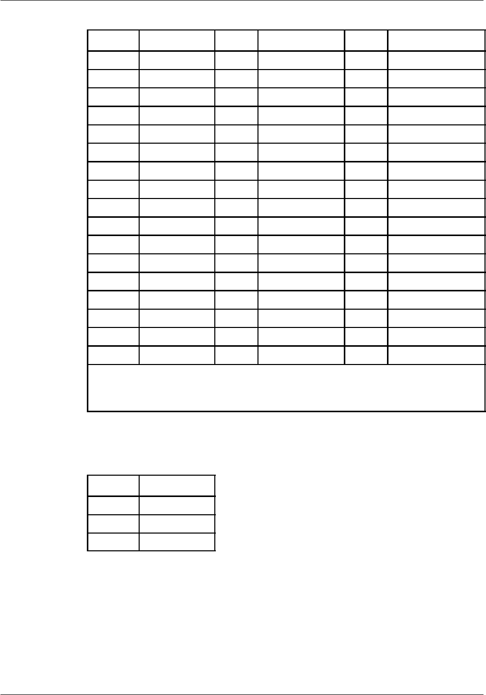
Board descriptionNortel Networks Confidential 2--19
S12000 BTS Reference Manual
Copyright ©2002--2005 Nortel Networks
Pin no. Purpose Pin no. Purpose Pin no. Purpose
50 GND 33 DALI 21 17 GND
49 DTA3 32 DALI 20 16 DALI 11
48 DTA2 31 DALI 19 15 DALI 10
47 GND 30 GND 14 DALI 9
46 DALI 31 29 DALI 18 13 GND
45 DALI 30 28 DALI 17 12 DALI 8
44 DALI 29 27 DALI 16 11 DALI 7
43 DALI 28 26 GND 10 DALI 6
42 GND 25 GND 9GND
41 DALI 27 24 DTA1 8DALI 5
40 DALI 26 23 DTA0 7DALI 4
39 DALI 25 22 GND 6DALI 3
38 GND 21 DALI 15 5GND
37 DALI 24 20 DALI 14 4DALI 2
36 DALI 23 19 DALI 13 3DALI 1
35 DALI 22 18 DALI 12 2DALI 0
34 GND 1GND
Legend:
DALI Internal Alarm Detection
GND Ground
Table 2--9 Ext. NP. pin connections
Pin no. Purpose
1(--) 48 V
2GND
3(+) 48 V
Table 2--10 PWR pin connections

Board description Nortel Networks Confidential
2--20
PE/DCL/DD/0142
411--9001--142 Standard 15.102/EN May 2005 Copyright ©2002--2005 Nortel Networks
Pin no. Purpose Pin no. Purpose
6 1 GND
7 2 RXDBG
8 3 TXDBG
9 4 PCBUG0
5GND
Table 2--11 P0 (Debug) pin connections
Pin no. Purpose Pin no. Purpose
1TCK 2GND
3TDO 4+5
5TMS 6
7 8
9TDI 10 GND
Table 2--12 P1 (EPLD JTAG) port pin connections
2.2.2.4 Electrical characteristics
The RECAL board is powered by a nominal 48 V DC. The nominal supply current
is approximately 600 mA.
A DC/DC converter (48 V to 5 V) on the board supplies logic circuits with +5 V
DC. The +5 V DC supply is available on the EXT.P external connector (and P5
internal connector) for the possible heating resistors mounted on the ALPRO
boards.
A second DC/DC isolated stages converter (5 V to 12 V) provides external alarm
detection circuits with +12 V DC isolated supply.
A EMC filter is designed on the board between 48 V DC input and the primary stage
of the DC/DC (48 V to 5 V) converter.
Its maximum consumption is 15 W.

Board descriptionNortel Networks Confidential 2--21
S12000 BTS Reference Manual
Copyright ©2002--2005 Nortel Networks
2.2.3 List of connected internal alarms
Connected internal alarms are the only internal alarms that can be used. The list of
alarms and the corresponding DALI pins (internal alarm detection) on the INT0
connector are identified in the following tables:
Table 2--13 – S12000 Indoor BTS (base and extension cabinets)
Table 2--15 – S12000 Outdoor BTS (base and extension cabinets)
O
r
i
g
i
n
A
l
a
r
m
D
A
L
I
REC
A
L
INT
O
r
i
g
i
n
A
l
arm
D
A
L
I
R
E
C
A
L
I
N
T
connector PIn
F--type converter High temperature Converter F0 DALI80 60
Behavior signal Converter F0 DALI81 19
High temperature Converter F1 DALI82 40
Behavior signal Converter F1 DALI83 61
Doors Door alarm DALI87 21
VSWR--meter VSWR0 Level 1 fault DALI33 43
VSWR0 Level 2 fault DALI34 2
VSWR0 Level 3 fault DALI35 23
VSWR1 Level 1 fault DALI37 3
VSWR1 Level 2 fault DALI38 24
VSWR1 Level 3 fault DALI39 45
VSWR2 Level 1 fault DALI41 46
VSWR2 Level 2 fault DALI42 5
VSWR2 Level 3 fault DALI43 26
VSWR3 Level 1 fault DALI45 6
VSWR3 Level 2 fault DALI46 27
VSWR3 Level 3 fault DALI47 48
VSWR4 Level 1 fault DALI49 28
VSWR4 Level 2 fault DALI50 49
VSWR--meter VSWR4 Level 3 fault DALI51 8
VSWR5 Level 1 fault DALI53 9
VSWR5 Level 2 fault DALI54 30
VSWR5 Level 3 fault DALI55 51
VSWR6 Level 1 fault DALI57 31

Board description Nortel Networks Confidential
2--22
PE/DCL/DD/0142
411--9001--142 Standard 15.102/EN May 2005 Copyright ©2002--2005 Nortel Networks
Origin RECAL INT
connector PIn
DALIAlarm
Origin RECAL INT
connector PIn
DALIAlarm
VSWR6 Level 2 fault DALI58 52
VSWR6 Level 3 fault DALI59 11
VSWR7 Level 1 fault DALI61 53
VSWR7 Level 2 fault DALI62 12
VSWR7 Level 3 fault DALI63 33
VSWR8 Level 1 fault DALI65 13
VSWR8 Level 2 fault DALI66 55
VSWR8 Level 3 fault DALI67 14
VSWR9 Level 1 fault DALI69 56
VSWR9 Level 2 fault DALI70 15
VSWR9 Level 3 fault DALI71 36
VSWR10 Level 1 fault DALI73 16
VSWR10 Level 2 fault DALI74 37
VSWR10 Level 3 fault DALI75 58
VSWR11 Level 1 fault DALI77 38
VSWR11 Level 2 fault DALI78 59
VSWR11 Level 3 fault DALI79 39
LNA LNA0 fault DALI32 1
LNA1 fault DALI36 44
LNA2 fault DALI40 4
LNA3 fault DALI44 47
LNA4 fault DALI48 7
LNA5 fault DALI52 29
LNA6 fault DALI56 10
LNA7 fault DALI60 32
LNA8 fault DALI64 54
LNA9 fault DALI68 35
LNA10 fault DALI72 57
LNA11 fault DALI76 17
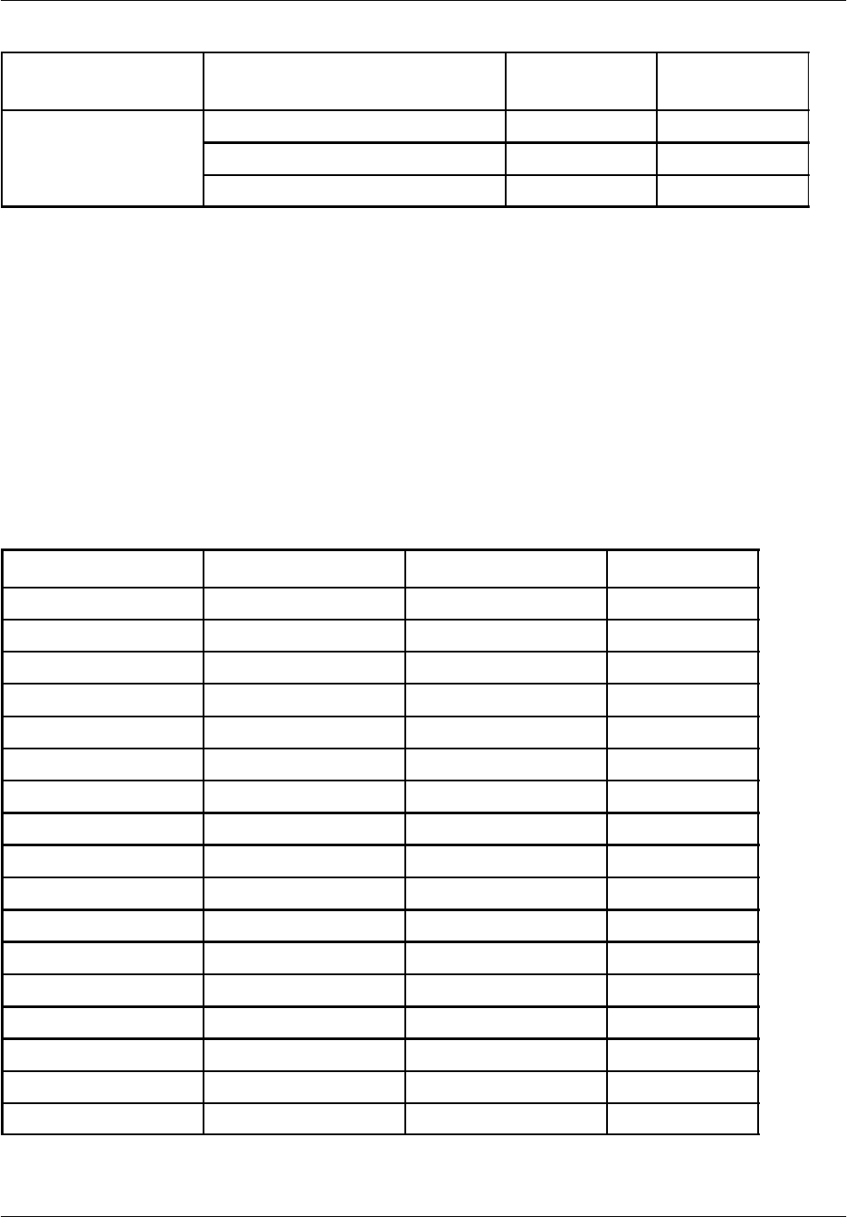
Board descriptionNortel Networks Confidential 2--23
S12000 BTS Reference Manual
Copyright ©2002--2005 Nortel Networks
Origin RECAL INT
connector PIn
DALIAlarm
Origin RECAL INT
connector PIn
DALIAlarm
Blower Blower_ALA1 DALI84 20
Blower_ALA2 DALI85 41
Blower_ALA3 DALI86 62
Table 2--13 List of alarms and INT0 connector DALIs
(S12000 Indoor BTS, base and extension cabinets)
The values of this table correspond to the static wiring scheme between COMICO
and RECAL.
In function of the configuration and of the BTS cabling, the logical value associated
to the origin of alarms can be different from the static value.
For example, the following table gives the correspondence between static values
and logical values for the 3H4D+RxF S444 an 3 H4D S012 configuration.
Static Values 3 H4D+RxF S444 3 H4D S012 DALI
LNA0 X X
VSWR0 Level 1 fault X X
VSWR0 Level 2 fault X X
VSWR0 Level 3 fault X X
LNA1 LNA0 LNA0 DALI36
VSWR1 Level 1 fault VSWR0 Level 1 fault VSWR0 Level 1 fault DALI37
VSWR1 Level 2 fault VSWR0 Level 2 fault VSWR0 Level 2 fault DALI38
VSWR1 Level 3 fault VSWR0 Level 3 fault VSWR0 Level 3 fault DALI39
LNA2 X X
VSWR2 Level 1 fault X X
VSWR2 Level 2 fault X X
VSWR2 Level 3 fault X X
LNA3 LNA1 LAN1 DALI44
VSWR3 Level 1 fault VSWR1 Level 1 fault VSWR1 Level 1 fault DALI45
VSWR3 Level 2 fault VSWR1 Level 2 fault VSWR1 Level 2 fault DALI46
VSWR3 Level 3 fault VSWR1 Level 3 fault VSWR1 Level 3 fault DALI47
LNA4 X X

Board description Nortel Networks Confidential
2--24
PE/DCL/DD/0142
411--9001--142 Standard 15.102/EN May 2005 Copyright ©2002--2005 Nortel Networks
Static Values DALI3 H4D S0123 H4D+RxF S444
VSWR4 Level 1 fault X X
VSWR4 Level 2 fault X X
VSWR4 Level 3 fault X X
LNA5 LNA2 LNA2 DALI52
VSWR5 Level 1 fault VSWR2 Level 1 fault VSWR2 Level 1 fault DALI53
VSWR5 Level 2 fault VSWR2 Level 2 fault VSWR2 Level 2 fault DALI54
VSWR5 Level 3 fault VSWR2 Level 3 fault VSWR2 Level 3 fault DALI55
LNA6 X X
VSWR6 Level 1 fault X X
VSWR6 Level 2 fault X X
VSWR6 Level 3 fault X X
LNA7 LNA7 X60
VSWR7 Level 1 fault X X
VSWR7 Level 2 fault X X
VSWR7 Level 3 fault X X
LNA8 X X
VSWR8 Level 1 fault X X
VSWR8 Level 2 fault X X
VSWR8 Level 3 fault X X
LNA9 LNA9 X68
VSWR9 Level 1 fault X X
VSWR9 Level 2 fault X X
VSWR9 Level 3 fault X X
LNA10 LNA11 X72
VSWR10 Level 1 fault X X
VSWR10 Level 2 fault X X
VSWR10 Level 3 fault X X
LNA11 X X
VSWR11 Level 1 fault X X
VSWR11 Level 2 fault X X
VSWR11 Level 3 fault X X
Table 2--14 Example of alarm affectation in function of S12000 Indoor configuration

Board descriptionNortel Networks Confidential 2--25
S12000 BTS Reference Manual
Copyright ©2002--2005 Nortel Networks
Note: An X in a column indicates that the alarm is not used with a particular
configuration
O
r
i
g
i
n
A
l
a
r
m
D
A
L
I
REC
A
L
INT
O
r
i
g
i
n
A
l
arm
D
A
L
I
R
E
C
A
L
I
N
T
connector PIn
F--type converter High temperature Converter F0 DALI80 60
Behavior signal Converter F0 DALI81 19
High temperature Converter F1 DALI82 40
Behavior signal Converter F1 DALI83 61
Doors Door alarm DALI87 21
VSWR--meter VSWR0 Level 1 fault DALI77 43
VSWR0 Level 2 fault DALI78 2
VSWR0 Level 3 fault DALI79 23
VSWR1 Level 1 fault DALI73 3
VSWR1 Level 2 fault DALI74 24
VSWR1 Level 3 fault DALI75 45
VSWR2 Level 1 fault DALI69 46
VSWR2 Level 2 fault DALI70 5
VSWR2 Level 3 fault DALI71 26
VSWR3 Level 1 fault DALI65 6
VSWR3 Level 2 fault DALI66 27
VSWR3 Level 3 fault DALI67 48
VSWR4 Level 1 fault DALI61 28
VSWR4 Level 2 fault DALI62 49
VSWR--meter VSWR4 Level 3 fault DALI63 8
VSWR5 Level 1 fault DALI57 9
VSWR5 Level 2 fault DALI58 30
VSWR5 Level 3 fault DALI59 51
VSWR6 Level 1 fault DALI53 31
VSWR6 Level 2 fault DALI54 52
VSWR6 Level 3 fault DALI55 11
VSWR7 Level 1 fault DALI49 53
VSWR7 Level 2 fault DALI50 12
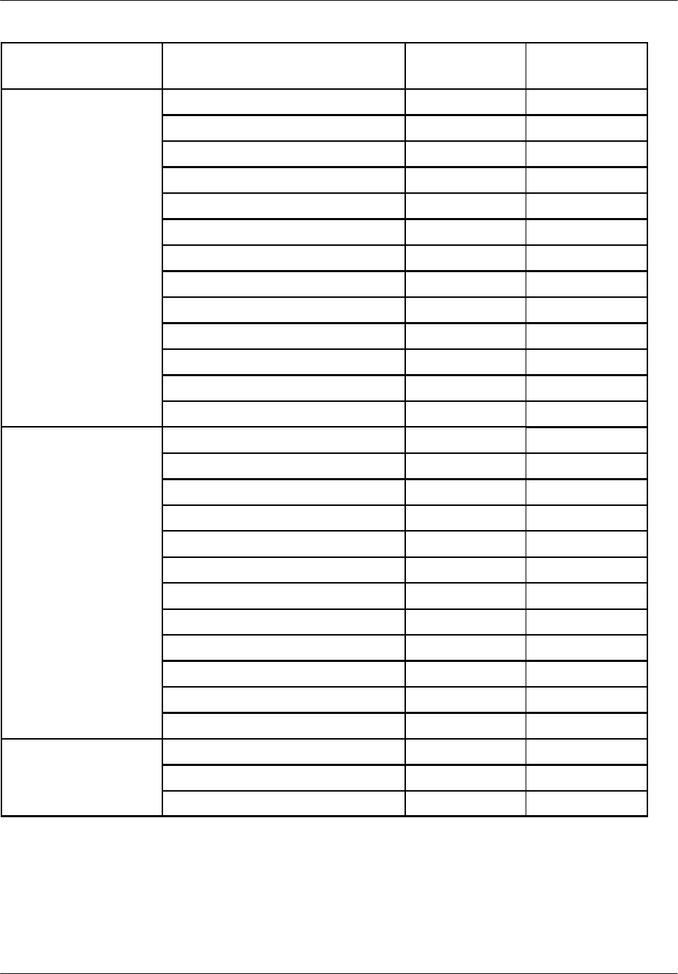
Board description Nortel Networks Confidential
2--26
PE/DCL/DD/0142
411--9001--142 Standard 15.102/EN May 2005 Copyright ©2002--2005 Nortel Networks
Origin RECAL INT
connector PIn
DALIAlarm
Origin RECAL INT
connector PIn
DALIAlarm
VSWR7 Level 3 fault DALI51 33
VSWR8 Level 1 fault DALI45 13
VSWR8 Level 2 fault DALI46 55
VSWR8 Level 3 fault DALI47 14
VSWR9 Level 1 fault DALI41 56
VSWR9 Level 2 fault DALI42 15
VSWR9 Level 3 fault DALI43 36
VSWR10 Level 1 fault DALI37 16
VSWR10 Level 2 fault DALI38 37
VSWR10 Level 3 fault DALI39 58
VSWR11 Level 1 fault DALI33 38
VSWR11 Level 2 fault DALI34 59
VSWR11 Level 3 fault DALI35 39
LNA LNA0 fault DALI76 1
LNA1 fault DALI72 44
LNA2 fault DALI68 4
LNA3 fault DALI64 47
LNA4 fault DALI60 7
LNA5 fault DALI56 29
LNA6 fault DALI52 10
LNA7 fault DALI48 32
LNA8 fault DALI44 54
LNA9 fault DALI40 35
LNA10 fault DALI36 57
LNA11 fault DALI32 17
Blower Cooler_0 DALI84 20
Cooler_1 DALI85 41
Hood_Alarm DALI86 62
Table 2--15 List of alarms and INT0 connector DALIs
(S12000 Outdoor BTS, base and extension cabinets)

Board descriptionNortel Networks Confidential 2--27
S12000 BTS Reference Manual
Copyright ©2002--2005 Nortel Networks
2.2.4 List of unprotected external alarms
The following pins on the INT1 connector can be used to receive up to
32 unprotected external alarms:
DALI 0 to DALI 20
MLC
The above pins presently are not used in the S12000 Indoor BTS.
Table 2--16 identifies the DALIs in the S12000 Outdoor BTS.
Origin Alarm DALI number
AC MAIN ALARM Main breaker DALI 0
SURGE ALARM Surge fail DALI 1
AC--DC RECTIFIERS
A
L
A
R
M
S
AC fault DALI 2
A
L
A
RMS DC fault DALI 3
Over temperature DALI 4
Load1 threshold DALI 5
PCU protective devices DALI 6
Battery on discharge DALI 7
USER ALARMS User 1 DALI 8
User 2 DALI 9
User 3 DALI 11
User 4 DALI 12
User 5 DALI 13
BATTERY BREAKER
ALARM
Disconnected battery DALI 14
EXTERNAL BATTERY
A
L
A
R
M
Thermal fault DALI 15
A
L
A
RM DC breaker fault DALI 16
Door open DALI 17
AC breaker fault DALI 18
Surge DALI 19
Spare DALI 20
Not used DALI 21
Not used DALI 22 to DALI 24

Board description Nortel Networks Confidential
2--28
PE/DCL/DD/0142
411--9001--142 Standard 15.102/EN May 2005 Copyright ©2002--2005 Nortel Networks
Origin DALI numberAlarm
Not used DALI 25 to DALI 27
Not used DALI 28 to DALI 31
Table 2--16 Unprotected external alarms
(S12000 Outdoor BTS, base and extension cabinets)

Board descriptionNortel Networks Confidential 2--29
S12000 BTS Reference Manual
Copyright ©2002--2005 Nortel Networks
2.3 ALPRO board
The ALPRO board protects up to eight external alarms and up to two remote
controls of the RECAL board.
2.3.1 Principle
The external alarms and remote controls are intended to be connected to equipment
outside the cabinets. This equipment may be connected, temporarily or
permanently, to outside line conductors affected by electrical disturbances. The
ALPRO board protects against these disturbances.
One ALPRO board protects half of the external interfaces available in the RECAL
board. There may therefore be two ALPRO boards for one RECAL board.
Depending on how many external alarms are used, one or two ALPRO boards may
be installed.
2.3.2 Description
The ALPRO board (see Figure 2--6 presented in S12000 Outdoor configuration)
provides only secondary protection. Primary protection devices are associated with
the board to protect the lines themselves. A cable linking the board ground to a
cabinet ground bar discharges energy caused by outside disturbances.
2.3.2.1 External alarm protection circuit
The first part of the external alarm protection circuit comprises a surge arrestor and
thermal resistors, which protect the board against power surges and limit the current
in wires and connectors.
The second part limits the voltage and current returning to the RECAL board. It
consists of transils and thermal resistors.
2.3.2.2 Remote control protection circuit
The first part of the remote control protection circuit comprises a surge arrestor and
thermal resistors, which protect the board against power surges and limit the current
in wires and connectors.
The second part protects the relays and connections of the RECAL board. It consists
mainly of thermal resistors.
2.3.3 S12000 Outdoor BTS environmental conditions
The ALPRO board is located in a sealed environment inside the skirting of the
cabinet. It is designed to operate at temperatures between --40°C(--40°F) and +80°C
(176°F).
Two thermoresistors supplied with +5 V prevent condensation inside the case of the
ALPRO card.
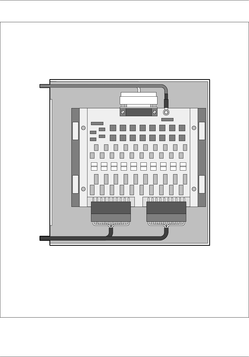
Board description Nortel Networks Confidential
2--30
PE/DCL/DD/0142
411--9001--142 Standard 15.102/EN May 2005 Copyright ©2002--2005 Nortel Networks
NORTEL
Figure 2--6 ALPRO board

Board descriptionNortel Networks Confidential 2--31
S12000 BTS Reference Manual
Copyright ©2002--2005 Nortel Networks
2.3.4 S12000 Indoor BTS environmental conditions
ALPRO modules are located at the top of the radio cabinet. The precise location is
presented on the overview figure.
2.3.5 Connectors
The ALPRO board has three connectors:
A 25--pin male connector connects the ALPRO board to the RECAL board:
Pin no. Purpose Pin no. Purpose
14 DALE0 1ME
15 ME 2DALE1
16 DALE3 3DALE2
17 DALE4 4ME
18 ME 5DALE5
19 DALE7 6DALE6
20 7ME
21 +5 V 8
22 ETC0B 9ETC0A
23 MLC 10 +5 V
24 ETC1B 11 ETC1A
25 12 MLC
13
Legend:
ETC Remote Control
DALE External Alarm Protected Detection
ME External ground
Table 2--17 ALPRO 25--pin connections
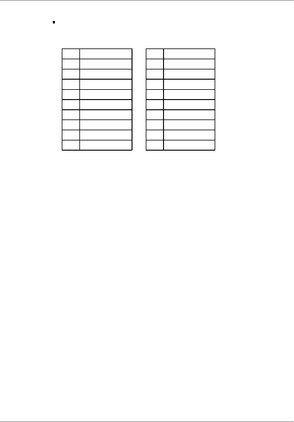
Board description Nortel Networks Confidential
2--32
PE/DCL/DD/0142
411--9001--142 Standard 15.102/EN May 2005 Copyright ©2002--2005 Nortel Networks
Two 10--pin connectors connect the ALPRO board to the external alarms:
Connector J1 Connector J2
1TC0A 1NALE4
2TC0B 2PALE4
3TC1A 3NALE3
4TC1B 4PALE3
5NALE7 5NALE2
6PALE7 6PALE2
7NALE6 7NALE1
8PALE6 8PALE1
9NALE5 9NALE0
10 PALE5 10 PALE0
Table 2--18 ALPRO 10--pin connections

Board descriptionNortel Networks Confidential 2--33
S12000 BTS Reference Manual
Copyright ©2002--2005 Nortel Networks
2.4 F--type converter
2.4.1 Principle
The F--type converter converts a 48 V DC voltage into two power sources, --15 V
and +15 V. It powers the radio equipments such as the Low Noise Amplifiers
(LNA), the variable gain amplifiers and the VSWR measuring devices.
2.4.2 Description
The F--type converter has a switch on its front panel that can be used to disconnect
the input voltage. It also has two outputs that can be connected in parallel with
identical outputs of another F--type converter.
2.4.2.1 Input voltage
Nominal input voltage: 48 V (40.5 V to 57 V)
2.4.2.2 Output voltages
The two output voltages supplied by the converter are as follows:
Source 1:
Nominal voltage: +15 V Nominal current: 7 A
Source 2:
Nominal voltage: --15 V Nominal current: 4 A
Output voltages can be individually adjusted up to +15% and --5% of nominal
voltage.
2.4.2.3 Alarms
Several alarm signals can be generated, in the following cases:
One of the two output voltages is either lower than the Low Voltage Limit (LVL)
or higher than the High Voltage Limit (HVL). These limit voltages are:
•
LVL: 13.25 V ±0.25 V
•
HVL: 18.5 V ±0.5 V
The switch on the front panel is set to “OFF”.
The converter temperature is too high.
Finally, an event alarm is generated when there is a logic OR between the other
alarms.

Board description Nortel Networks Confidential
2--34
PE/DCL/DD/0142
411--9001--142 Standard 15.102/EN May 2005 Copyright ©2002--2005 Nortel Networks
2.4.3 Front panel
The F--type converter front panel has several connectors and LEDs (see
Figure 2--7).
2.4.3.1 LEDs
Two green LEDs provide information on the status of the converter.
2.4.3.2 Connectors
Two connectors are on the front panel of the converter:
A female, Sub--D, 15--pin connector supplies output voltages and alarm signals.
A male, 3W3, Sub--D connector receives input voltages.
1GND
215 V alarm
3Switch “OFF” alarm
4High temperature alarm
5GND
6-- 1 5 V a l a r m
7GND
8Event alarm
9GND
10 GND
11 15 V
12 15 V
13 -- 1 5 V
14 -- 1 5 V
15 GND
Table 2--19 Output voltages and alarm signals connector
1-- 4 8 V
2Mechanical ground
3+48 V
Table 2--20 Input voltages connector
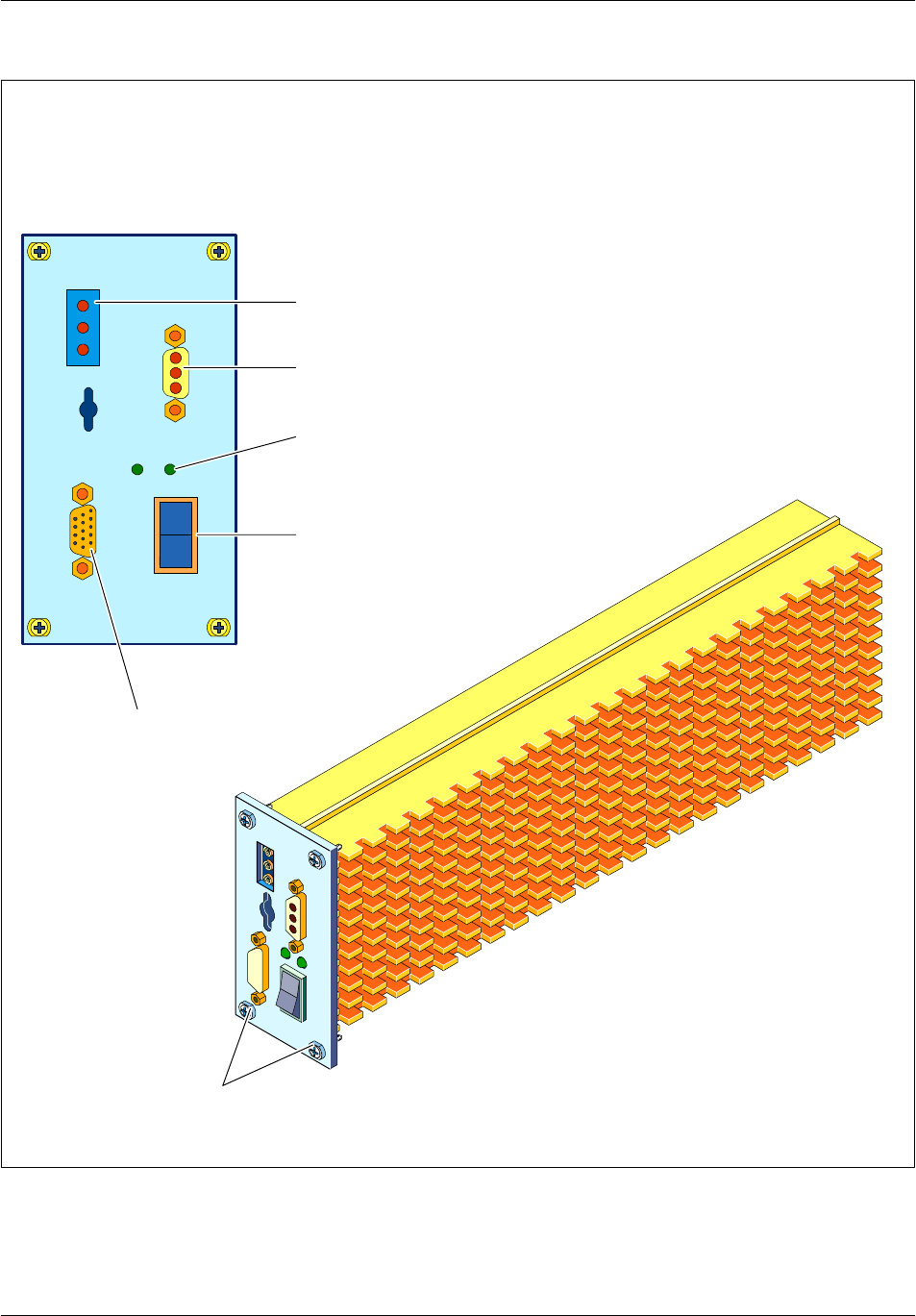
Board descriptionNortel Networks Confidential 2--35
S12000 BTS Reference Manual
Copyright ©2002--2005 Nortel Networks
Test points
LEDs
Switch
Power in
Power
out/alarms
Screws
--15V
--15V
0V
+15V
+15V
I
O
Figure 2--7 F--type converter

Board description Nortel Networks Confidential
2--36
PE/DCL/DD/0142
411--9001--142 Standard 15.102/EN May 2005 Copyright ©2002--2005 Nortel Networks
2.5 RF Combiner
2.5.1 Principle
There are three types of RF Combiner modules:
duplexer--only (D)
hybrid two--way duplexer (H2D)
hybrid four--way duplexer (H4D)
The functional diagrams of each RF Combiner type are shown in Figure 2--8.
Table 2--21 describes the components in each type of RF Combiner module.
RF Combiner Type Contents
D-- Duplexer
-- Reception Amplifier (LNA splitter)
-- VSWR Meter (optional)
H2D -- Duplexer
-- Reception Amplifier (LNA splitter)
T
w
o
w
a
y
t
r
a
n
s
m
i
s
s
i
o
n
c
o
u
p
l
i
n
g
--
T
wo--way transm
i
ss
i
on coup
l
i
ng
(H2D)
-- VSWR Meter (optional)
H4D -- Duplexer
-- Reception Amplifier (LNA splitter)
-- Four--way transmission coupling
(H4D)
-- VSWR Meter (optional)
Table 2--21 Content of RF Combiner modules
2.5.1.1 Duplexer
The duplexer allows transmission and reception to occur on the same antenna. This
reduces the number of antennas required for a cabinet. The duplexer also performs
filtering for reception and transmission.
When no receive filtering or transmit coupling is required, then the Tx--Filter (TxF)
module can be used instead of the duplexer.
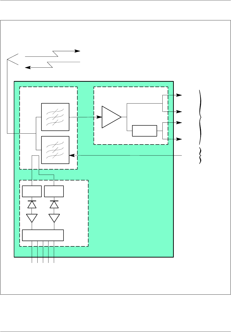
Board descriptionNortel Networks Confidential 2--37
S12000 BTS Reference Manual
Copyright ©2002--2005 Nortel Networks
Offset Offset
Duplexer LNA--splitter
+/--
LNA
-- 2 d B
Ext 0
Ext 1
Int 0
Int 1
RX in
TX in
RF combiner
Power supply and
three alarms
Antenna
Envelope
detector
VSWR
meter
To
RX--splitter
From
PAs
Figure 2--8 Duplexer--only (D) RF Combiner diagram
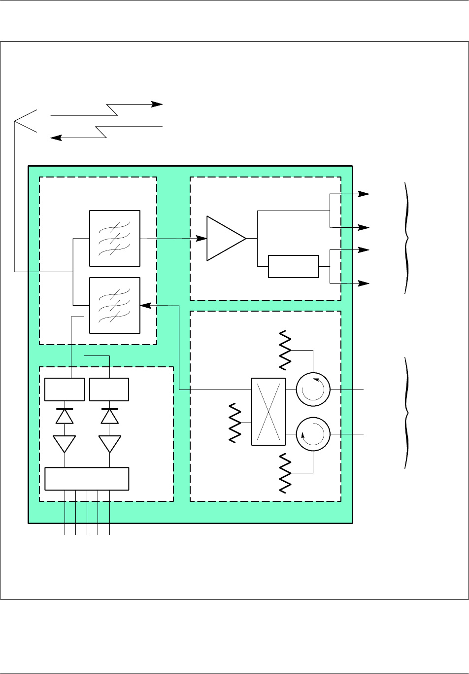
Board description Nortel Networks Confidential
2--38
PE/DCL/DD/0142
411--9001--142 Standard 15.102/EN May 2005 Copyright ©2002--2005 Nortel Networks
Offset Offset
Duplexer LNA--splitter
+/--
LNA
-- 2 d B
Ext 1
Ext 2
Int 1
Int 2
RX in
TX in
50 Ω
50 Ω
50 Ω
PA in 1
PA in 2
RF combiner
TX out
Power supply and
three alarms
Antenna
Hybrid coupler
Envelope
detector
VSWR
meter
To
RX--splitter
Frw
Reverse
Forward
From
e--PAs
Figure 2--9 H2D RF Combiner diagram
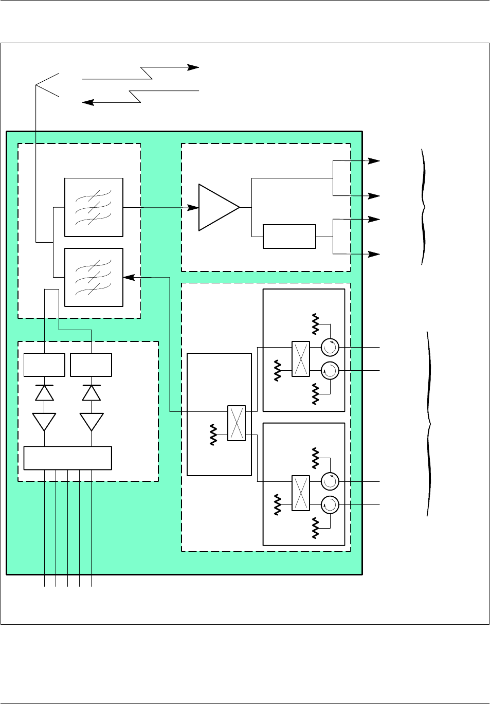
Board descriptionNortel Networks Confidential 2--39
S12000 BTS Reference Manual
Copyright ©2002--2005 Nortel Networks
Offset Offset
Duplexer LNA--splitter
+/--
LNA
-- 2 d B
Ext 0
Ext 1
Int 0
Int 1
RX in
TX in
50 Ω
PA in 1
PA in 2
RF combiner
Power supply and
three alarms
Antenna
Envelope
detector
VSWR
meter
50 Ω
50 Ω
PA in 3
PA in 4
TX out
Hybrid
coupler
Hybrid coupler
Hybrid coupler
To
RX--splitter
From
PAs
Figure 2--10 H4D RF Combiner diagram

Board description Nortel Networks Confidential
2--40
PE/DCL/DD/0142
411--9001--142 Standard 15.102/EN May 2005 Copyright ©2002--2005 Nortel Networks
2.5.1.2 Reception amplifier
The reception signal amplifier, also called the LNA--splitter, has two functions:
amplifies the signal from the antenna using a Low Noise Amplifier (LNA)
splits the signal from the antenna into four signals
The LNA--splitter has the following attenuation or gain values:
The LNA has a nominal gain of 28.5 dB (GSM 850) and 32 dB (GSM 1900).
The two splitter stages cause attenuation less than 7 dB.
A 2 dB attenuator handles differences in cable attenuation between the two
extension outputs (EXT) and the two internal outputs (INT). The two extension
outlets, which are not used at present, will make future configuration upgrades
possible.
The LNA--splitter is supplied with ±15 V DC (±5%) and its maximum current
consumption is 370 mA (+ 15 V), 50 mA (-- 15 V). The module generates an alarm
if LNA consumption deviates by more than 30% from the nominal value.
On the front of the LNA--splitter board, there is a 9--pin male connector whose pin
connection is as follows:
1-- 1 5 V
20V
3Alarm
4Not used
5+15V
60V
70V
8Not used
9+15V
Table 2--22 Amplifier pin connections

Board descriptionNortel Networks Confidential 2--41
S12000 BTS Reference Manual
Copyright ©2002--2005 Nortel Networks
2.5.1.3 Hybrid transmission coupling
According to the hybrid coupling type, transmission coupling consists of a single
hybrid coupler for H2D configurations or three hybrid couplers mounted in two
stages for H4D configurations.
The two--way hybrid coupler (H2D) consists of:
two isolators, one at each input port, which allows the protection of the Power
Amplifier (PA) against reflected signals, and also permits the isolation necessary
between transmitters.
a hybrid coupler, which combines two transmission signals on only one port.
This subsystem is part of the RF Combiner module (H2D, or H4D).
The maximum attenuation is an RF Combiner module is dedicated to one frequency
band.
When any transmission coupling system is requested (in the case of one TRX per
antenna), the Tx--Filter (Tx--F) module can be used with two duplexer--only (D)
modules in order to provide Rx main and diversity signals.
The Tx--Filter module is dedicated to one frequency band.
Refer to Paragraph 2.6 “Tx--Filter module” on page 2--48 for information about the
Tx--Filter.
2.5.1.4 VSWR--meter
The VSWR--meter can be included as an optional unit in the RF Combiner module
or in the Tx--Filter module.
The VSWR--meter allows the signal strength of the voltage standing wave ratio
(VSWR) to be monitored on the antenna connector and to verify the connection
between the antenna and the BTS. This module needs BTS signals transmission to
be able to switch on (no alarm with “Receive antenna” only)
The VSWR--meter receives transmitted and reflected signals sampled through two
directional antennas located inside the duplexer unit or Tx--Filter unit.
The transmit and receive signals are first converted into two DC voltages by using
envelope detection. Two logarithmic amplifiers, one for transmit power signal, and
one for reflected power signal, then amplify both converted signals.
The two channels are added and subtracted to obtain the stationary wave ratio. This
value is compared to three thresholds (1.7:1, 2:1, and 3:1), each of which triggers
an alarm if it is exceeded.

Board description Nortel Networks Confidential
2--42
PE/DCL/DD/0142
411--9001--142 Standard 15.102/EN May 2005 Copyright ©2002--2005 Nortel Networks
2.5.2 RF Combiner front panels
The front panels of the RF Combiner types are shown in Figure 2--11
to Figure 2--13.
2.5.2.1 Duplexer
The duplexer connectors on the front panel of the RF Combiner are:
a female 7/16 antenna connector
a female N type transmission connector
a female, SMA type connector (Rev)
a female, SMA type connector (Fwd)
A female, SMA type reception connector is present at the rear of the duplexer.
2.5.2.2 LNA--splitter
The connectors on the LNA--splitter front panel are:
two female, SMA type, output (EXT) connectors to the RX--splitter of the
extension rack
two female, SMA type, RX--splitter output (INT) connectors
a male, 9--pin power supply connector
A female, SMA type, radio signal input connector is present at the rear of the
LNA--splitter.
2.5.2.3 Transmission coupling
For duplexer--only configurations, the transmission signal input connector on the
front panel is a female, N type connector (TX--in). Duplexer Tx input is described
hereafter.
For H2D configurations, the connectors on the front panel are:
two female, N type, transmission signal input connectors (PA in)
a female, N type, output connector (TX--out)
a female, N type input connector (TX--in). Duplexer Tx input is described
hereafter
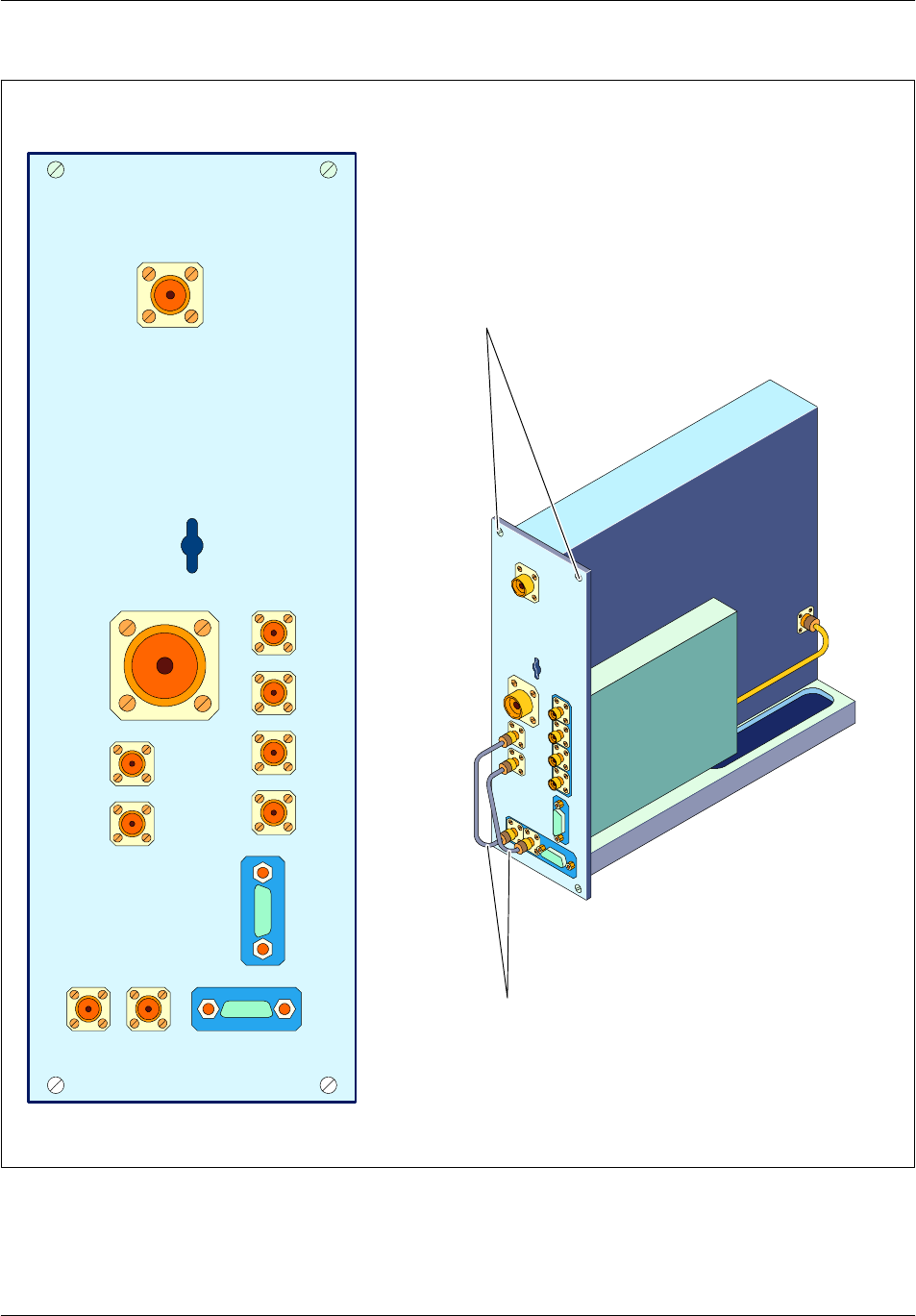
Board descriptionNortel Networks Confidential 2--43
S12000 BTS Reference Manual
Copyright ©2002--2005 Nortel Networks
Int_0 Int_1 Ext_1Ext_0
FwdAntenna
Pwr/
Alarm
TX_in
Rev
VSWR
Fwd
Rev
Pwr/
Alarm
Cables always provided
with VSWR meter
Screws
Figure 2--11 Duplexer--only (D) RF Combiner
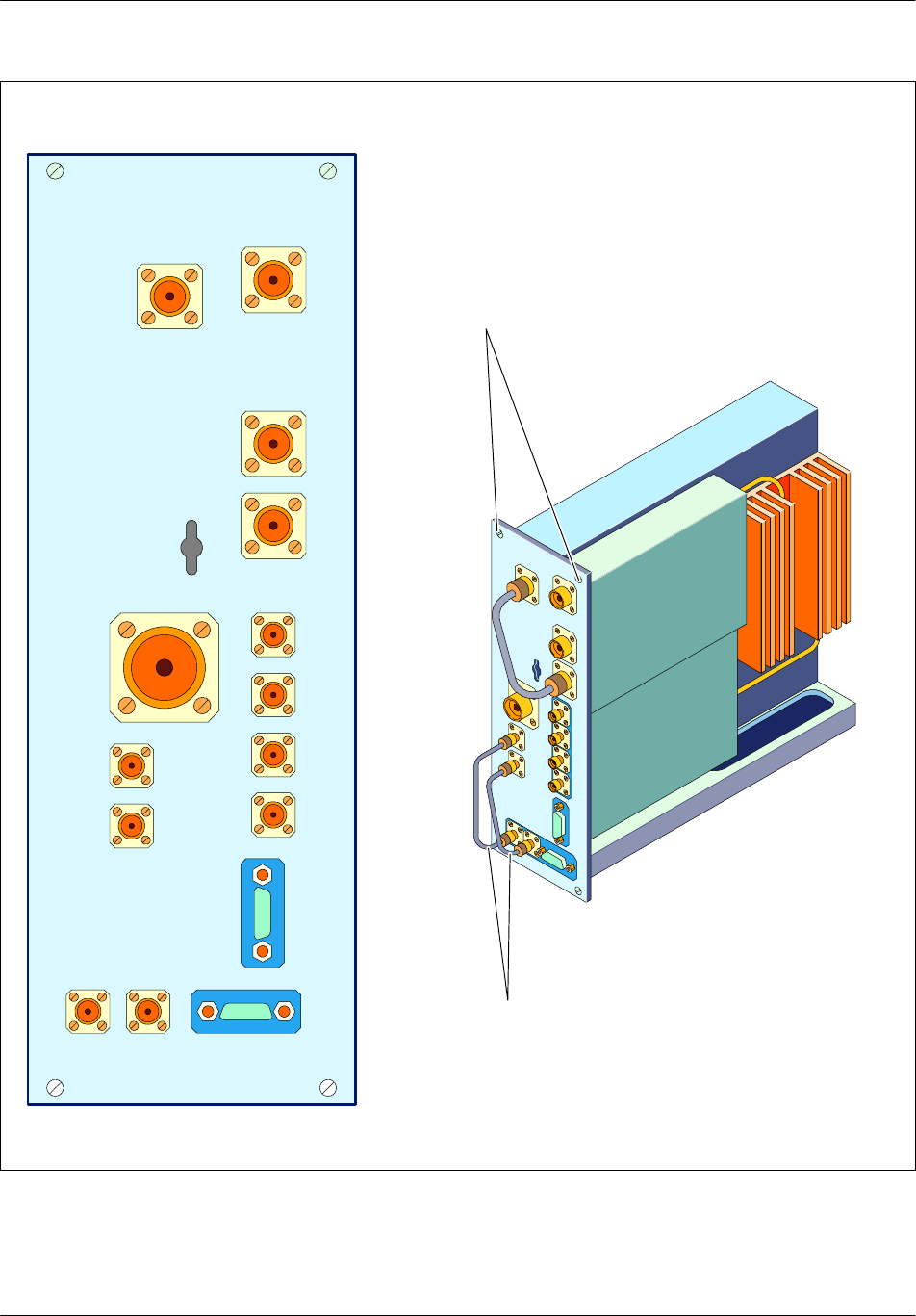
Board description Nortel Networks Confidential
2--44
PE/DCL/DD/0142
411--9001--142 Standard 15.102/EN May 2005 Copyright ©2002--2005 Nortel Networks
Pwr/Alarm
Int_0 Int_1 Ext_1Ext_0
FwdAntenna
Pwr/
Alarm
TX_in
PA_in PA _in TX_out
Rev
VSWR
Fwd
Cables always provided
with VSWR meter
Rev
Screws
Figure 2--12 Two--way hybrid duplexer (H2D) RF Combiner
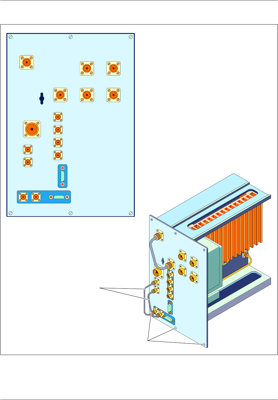
Board descriptionNortel Networks Confidential 2--45
S12000 BTS Reference Manual
Copyright ©2002--2005 Nortel Networks
Pwr/
Rev
Pwr/Alarm
Int_0 Int_1 Ext_1Ext_0
FwdRevAntenna
TX_in
TX_out
PA_in PA_in
PA_in PA_in
Alarm
VSWR
Fwd
Screws
Cables always provided
with VSWR meter
Figure 2--13 Four--way hybrid duplexer (H4D 1800/900 Mhz) RF Combiner
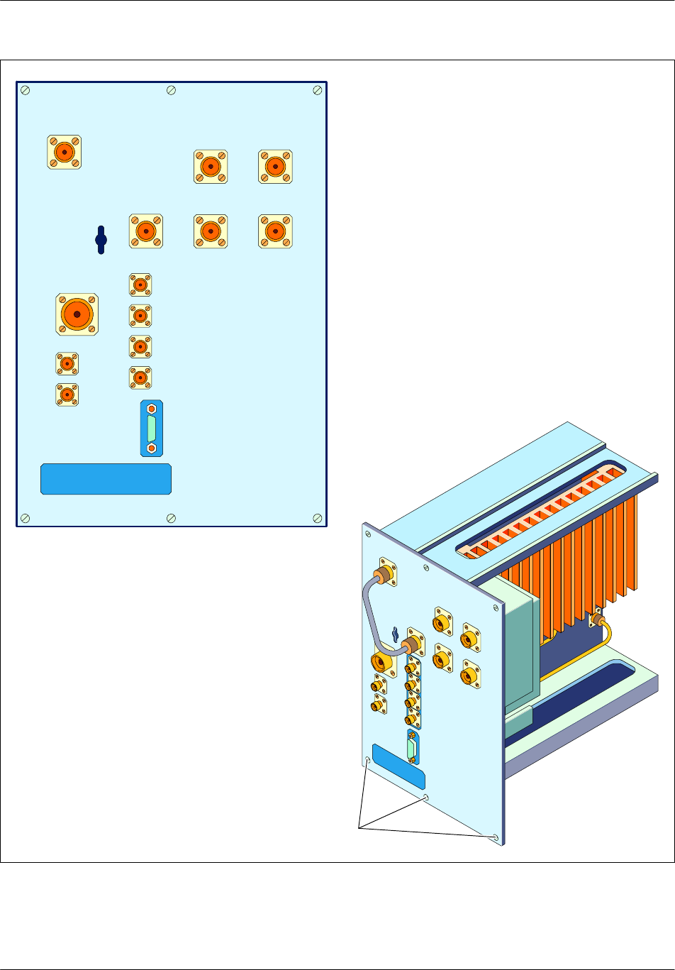
Board description Nortel Networks Confidential
2--46
PE/DCL/DD/0142
411--9001--142 Standard 15.102/EN May 2005 Copyright ©2002--2005 Nortel Networks
Pwr/
Rev
Pwr/Alarm
Int_0 Int_1 Ext_1Ext_0
FwdRevAntenna
TX_in
TX_out
PA_in PA_in
PA_in PA_in
Alarm
VSWR
Fwd
Screws
Figure 2--14 Four--way hybrid duplexer (H4D 850/1900 MHz) RF Combiner

Board descriptionNortel Networks Confidential 2--47
S12000 BTS Reference Manual
Copyright ©2002--2005 Nortel Networks
For H4D configurations, the connectors on the front panel are:
four female, N type, transmission signal input connectors (PA--in)
a female, N type, output connector (Tx--out)
a female, N type, input connector (Tx--in). Duplexer Tx input is described
hereafter.
2.5.2.4 VSWR--meter
The connectors on the VSWR--meter front panel are:
a female, SMA type, reflected power connector (Rev)
a female, SMA type, transmitted power connector (Fwd)
a male 9--pin, sub--D connector for power supply and alarms, with the following
pin connection:
1-- 1 5 V
20V
3Alarm 1
4Alarm 2
5+15V
60V
70V
8Alarm 3
9+15V
Table 2--23 VSWR pin connections

Board description Nortel Networks Confidential
2--48
PE/DCL/DD/0142
411--9001--142 Standard 15.102/EN May 2005 Copyright ©2002--2005 Nortel Networks
2.6 Tx--Filter module
The purpose of the Tx--Filter (Tx--F) is to filter the transmitted signal and to protect
the power amplifier (PA). The Tx--F does not contain a transmission coupling
system or a receiver filter.
The Tx--Filter module is composed of (see Figure 2--15):
a transceiver filter unit
a coupling system dedicated to the VSWR--meter
an optional VSWR--meter that monitors the link between the BTS and the
antenna.
The Tx--Filter module is used with the duplexer--only RF Combiner (D) to extend
configurations beyond two DRXs per cell. The Tx--Filter does not perform
reception functions and must be used with the RF Combiner (D) to ensure reception
distribution.
The Tx--Filter module can be equipped with an optional VSWR--meter which shares
the same front panel so that there is only one unit to plug into the BTS rack.
With or without the optional VSWR--meter, the Tx--Filter module is half the size
of the two--way hybrid (H2D) and duplexer--only (D) RF Combiner.
2.6.1 VSWR--meter
The function of the VSWR--meter (see Figure 2--16) is described in the section
“RF Combiner”.
The VSWR--meter connectors on the front panel of the Tx--Filter are the same as
those of the RF Combiner and are described in the section “RF Combiner
connectors”.
Although the VSWR--meter delivers three alarm lines, only two are reported to the
OMC--R because of COMICO constraints.
These alarm thresholds correspond to 2:1 and 3:1 VSWR values.
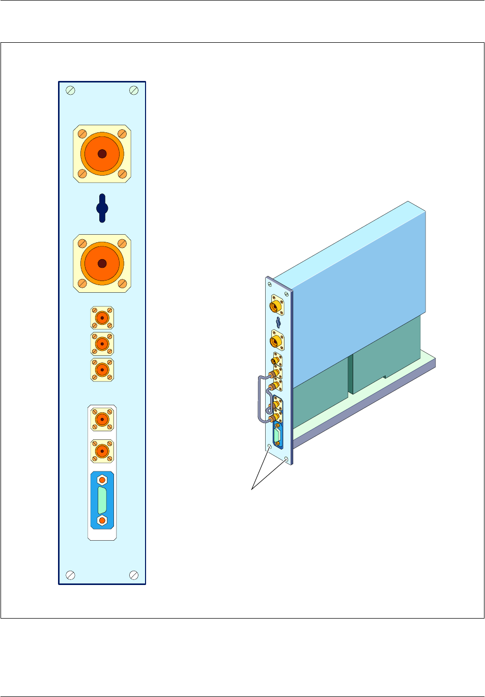
Board descriptionNortel Networks Confidential 2--49
S12000 BTS Reference Manual
Copyright ©2002--2005 Nortel Networks
PA_IN
Test
loop Fwd Rev Rev Fwd Pwr/Alarm
Antenna
Screws
Figure 2--15 Tx--Filter (Tx--F) module
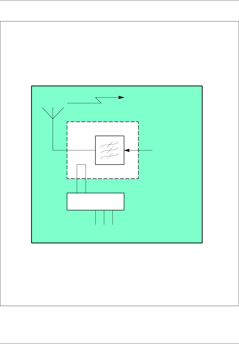
Board description Nortel Networks Confidential
2--50
PE/DCL/DD/0142
411--9001--142 Standard 15.102/EN May 2005 Copyright ©2002--2005 Nortel Networks
VSWR--meter
1
TX in (from PA)
2
Antenna
3Alarms
TX
Optional
Forward Reverse
Figure 2--16 Tx--Filter (Tx--F) functional diagram
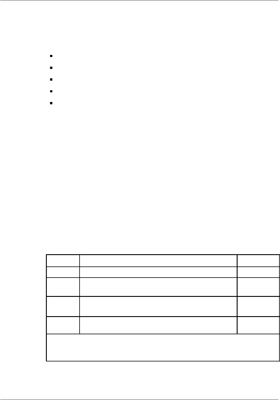
Board descriptionNortel Networks Confidential 2--51
S12000 BTS Reference Manual
Copyright ©2002--2005 Nortel Networks
2.7 Compact BCF (CBCF) module
This section provides a functional and physical description of the CBCF Module
and of the following CBCF Module boards:
CPCMI
CMCF Phase2
BCFICO
CBP
POWER ICO
2.7.1 Functional description
The CBCF Module performs functions common for a site and also manages its
alarm management unit, the RECAL board.
The base common functions of the BTS are performed by two main CBCF Module
boards: the CMCF and the CPCMI.
The CMCF Phase2 board performs the concentration, switching, and
synchronization functions of the BTS. The CPCMI board ensures the interface
between the external PCMs of the A--bis interface and the internal private PCMs.
Private PCM links connect the CBCF (via the CMCF) to the other BTS components.
The CBCF also uses private PCMs for internal communication between CBCF
boards.
The boards and their functions are identified in Table 2--24.
Board* Function Quantity
CPCMI ABIS double PCM link interface 1to3
CMCF
Phase2
Concentration, routing, and synchronization 1or2
BCFICO Interconnection between the CPCMI, CMCF
Phase2
boards and external communication links
1
CBP Interconnection between CPCMI, CMCF, and BCFICO
boards
1
* Legend:
CPCMI Compact PCM Interface CMCF Compact Main Common Functions
BCFICO Base Common Functions Interconnection CBP CBCF Back Panel
Table 2--24 CBCF module boards

Board description Nortel Networks Confidential
2--52
PE/DCL/DD/0142
411--9001--142 Standard 15.102/EN May 2005 Copyright ©2002--2005 Nortel Networks
2.7.2 Physical description
Although the CBCF Module boards are fitted into a compact module, the CMCF,
CPCMI, and BCFICO boards can be accessed from the front panel and replaced.
The aim is to reduce the number of boards, to take advantage of the new
technologies and to reach a high level of integration to allow software updating from
OMC without any intervention on the site.
Figure 2--17 show the CBCF module front panel.
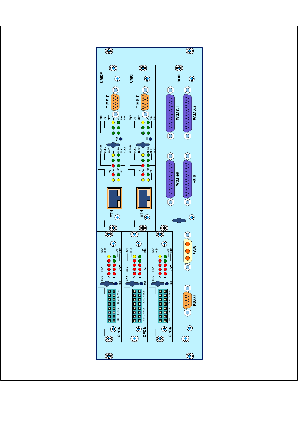
Board descriptionNortel Networks Confidential 2--53
S12000 BTS Reference Manual
Copyright ©2002--2005 Nortel Networks
Figure 2--17 S12000 BTS: CBCF module

Board description Nortel Networks Confidential
2--54
PE/DCL/DD/0142
411--9001--142 Standard 15.102/EN May 2005 Copyright ©2002--2005 Nortel Networks
2.7.3 CPCMI Board
2.7.3.1 S12000 CPCMI board
Depending on the requirements, the CBCF Module can contain one to three CPCMI
boards.
This Compact PCM interface board handles two PCMs. Both PCMs can be used for
the system Clock of the BTS.
2.7.3.2 Functional description
The CPCMI board ensures the interface between the external PCMs of the A--bis
interface and the internal private PCMs. This interfacing task corresponds to an
electrical level translation and a frame format conversion depending on the kind of
A--bis link (PCM E1/T1 or HDSL).
There are two types of CPCMI boards available used in accordance with the type
of A--bis interface:
CPCMI--E1
CPCMI--T1
The core of each board is generic and common to all, but each uses a different line
interface.
The CPCMI uses the n+1 redundancy scheme depending on:
the number of required TSs
the drop and insert scheme
the number of CPCMIs present in the package (three maximum)
The functional characteristics of the E1 and T1 boards are summarized in
Table 2--25.

Board descriptionNortel Networks Confidential 2--55
S12000 BTS Reference Manual
Copyright ©2002--2005 Nortel Networks
The functional diagram of the CPCMI is shown in Figure 2--18.
Function CPCMI-- E1 CPCMI--T1
Reception gain adaptation X X
Extraction of the binary rate for transmission to
the CMCF
X X
Reception and transmission buffer on two
frames to allow frame alignment
X X
Transmission alignment on the CMCF clock X X
Management of frame loss or doubling X X
Management of alarms, signalling, and loop
control
X X
Switch configuration for 120 Ohms or 75 Ohms X
Compliant with Recommendation G703 (HDB3
line coding)
X
Compliant with the G823--G824 standard (jitter
permitted)
X
CRC4 Management X
Adaptation of transmission to the cable length X
Compliant with ANSI T1.403 and T1.102 (B8ZS
coding)
X
Management of frame format (SF or ESF) X
CRC6 Management (for ESF) X
Alignment of external T1 PCM rate and internal
E1 PCM rate
X
Table 2--25 Functions of CPCMI--E1 and CPCMI--T1 boards
Synchronization
The timing signal is extracted from the PCM clock and sent to the CMCF (RCLK).
The local time is sent to the CMCF if there is no PCM timing signal (RCLK =
HLOC).
The CMCF selects one signal from the six received (one per PCM link) and
redistributes it as a reference for all A--bis transmissions (TCLK). This signal is also
the long term reference used to create the H4M timing reference.
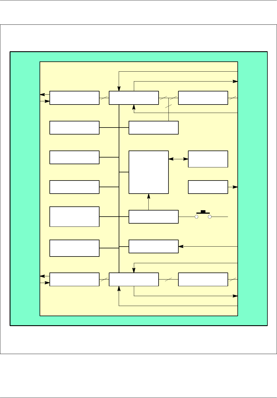
Board description Nortel Networks Confidential
2--56
PE/DCL/DD/0142
411--9001--142 Standard 15.102/EN May 2005 Copyright ©2002--2005 Nortel Networks
Line interface Transceiver Drivers
HDLC controllerEPLD
FEPROM
SRAM
Interface LEDs
Configuration
switch
TransceiverLine interface
Processing
unit
Reset logic
TEI register
Debug
interface
E1/T1
Drivers
TEI
CMCFA--bis
Transmission clock
Transmission clock
PCM0 reception
clock
Local clock
PCM1 reception
clock
Local clock
Private
PCM0
Private
PCM1
PCM1
E1 or T1
PCM0
E1 or T1
Figure 2--18 CPCMI board functional diagram

Board descriptionNortel Networks Confidential 2--57
S12000 BTS Reference Manual
Copyright ©2002--2005 Nortel Networks
2.7.3.3 Physical description
Processing Unit
The CPCMI processing unit has a rate of 4 MHz derived from a 16 MHz external
oscillator. It has a 128 Kbytes RAM capacity and a 16 Mbytes FEPROM capacity.
O&M communication occurs using a LAP--D on TS0 of the private PCM MIC0.
Front panel
The front panel contains the following:
one Reset button
ten LEDs
eight connectors
The CPCMI board is shown in Figure 2--19.
LEDs
The LEDs used on the front panel of the CPCMI board are described in Table 2--26.
Type No. of
LEDs
Label
(color) Meaning (when lit)
Board state
indicators
1BIST (yellow) The built--in self--test is
running or is stopped with a
default result.
1+5 V (green) The power is on.
1RDY (green) The board is operating
normally.
State indicators of
the external PCM
l
i
k
(
A
b
i
)
1SKP (red) The FIFO skip indicator is
commontobothPCMs.
link (
A
-- b i s ) 2LFA (red) The frame alignment is lost.
One LFA per PCM link.
2RRA (red) The receive remote alarm.
One RRA per PCM link.
2NOS (red) There is no signal. One NOS
per PCM link.
Table 2--26 LEDs on the front panel of the CPCMI board
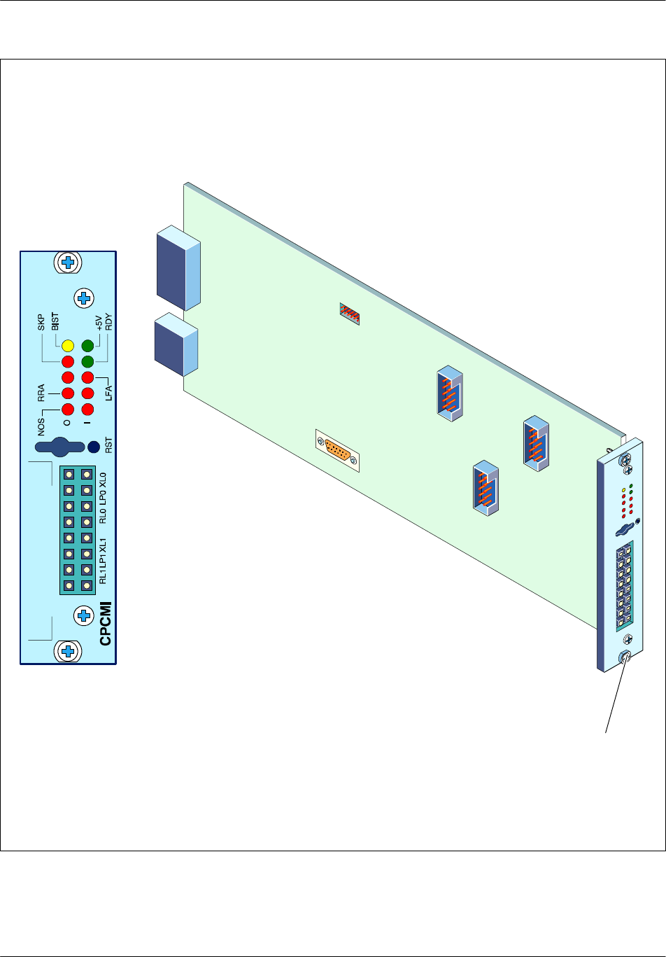
Board description Nortel Networks Confidential
2--58
PE/DCL/DD/0142
411--9001--142 Standard 15.102/EN May 2005 Copyright ©2002--2005 Nortel Networks
Screw
P13
P11
P10
P9
S2
S1
S3
Figure 2--19 CPCMI board

Board descriptionNortel Networks Confidential 2--59
S12000 BTS Reference Manual
Copyright ©2002--2005 Nortel Networks
The next table defines the relation between the PCM alarms and the front LED
status.
According to the priority order, when the simultaneous alarms are detected, only the
alarm with the highest priority is declared active.
PCM alarms CPCMI LEDs
Definition Priority NOS RRA LFA
LOS:
Loss Of Signal 1 (high) ON OFF OFF
AIS: Alarm Indication Signal 2ON ON ON
LFA:
Loss of Frame Alignment 3OFF OFF ON
FE:
Frame Error 4ON ON OFF
CRC:
loss of multi--frame
alignment
5OFF ON ON
RAI: Remote Alarm
Indication
6(low) OFF ON OFF
2.7.3.4 Switches
The switches are used to configure the following board characteristics:
cable length
line build out
line coding mode
framing mode
Fs/dl feature
The position of each switch is shown on Figure 2--20
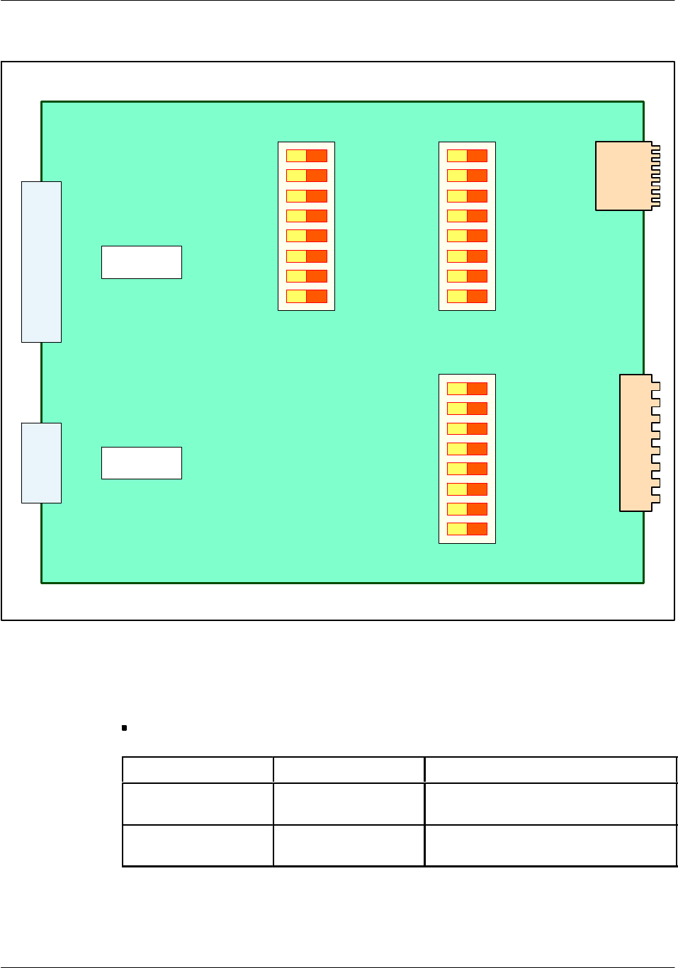
Board description Nortel Networks Confidential
2--60
PE/DCL/DD/0142
411--9001--142 Standard 15.102/EN May 2005 Copyright ©2002--2005 Nortel Networks
P10
ON (1)
CRC/RES
P9
AMI/B8ZS
FSDL
LS2
LS1
LS0
MT1
MT0
PCM1
OFF (0)
S2
CRC/RES
AMI/B8ZS
FSDL
LS2
LS1
LS0
MT1
MT0
PCM0
OFF (0)
S1
ON (1)
120 Ω
S3
0
1
2
3
4
5
6
7
75 Ω
P13
P11
Figure 2--20 CPCMI board: hardware switches
The next tables summarize the settings of each switch of CPCMI board.
S3 switch:
S3 switch T1 type E1 type
(0:3) -- =120: PCM1 120 Ω
=75: PCM1 75 Ω
(4:7) -- =120: PCM0 120 Ω
=75: PCM0 75 Ω
Table 2--27 CPCMI board: S3 switch
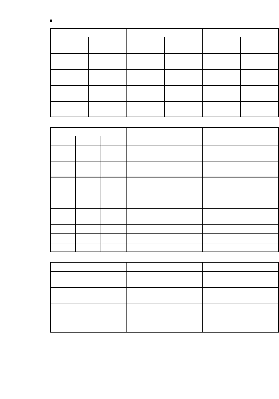
Board descriptionNortel Networks Confidential 2--61
S12000 BTS Reference Manual
Copyright ©2002--2005 Nortel Networks
S1andS2switches:
S1 and S2 switches T1 board E1 board
MT1 MT0 Framing
mode CRC mode Framing
mode
CRC
mode
0 0 F4
not available -- -- --
0 1 SF (or D4)
frame none single frame none
1 0 ESF frame see
CRC/RES multi--frame CRC4
1 1 F72
not available -- -- --
S1 and S2 switches T1 board E1 board
LS2 LS1 LS0
T
1
b
o
a
r
d
Cable length
E
1
b
o
a
r
d
Line Build Out
000 0 to 133 feet / 0dB
(0 to 40.58 meters) --
001 133 to 266 feet
(40.58 to 81.08 meters) --
010 266 to 399 feet
(81.08 to 121.61 meters) 75 Ω
011 399 to 533 feet
(121.61 to 162.46 meters) 120 Ω
100 533 to 655 feet
(162.46 to 199.64 meters) 120 Ω
101 -- 7 . 5 d B --
110 --15.0 dB 120 Ω
111 --22.5 dB --
S1 and S2 switches T1 board E1 board
FSDL =0 : FS/DL disabled
=1 : FS/DL enabled --
AMI/B8ZS =0 : AMI line coding
=1 : B8ZS line coding --
CRC/RES
=0 : CRC decoding
disabled
=1 : CRC decoding
enabled
--
Table 2--28 CPCMI board: S1 and S2 switches

Board description Nortel Networks Confidential
2--62
PE/DCL/DD/0142
411--9001--142 Standard 15.102/EN May 2005 Copyright ©2002--2005 Nortel Networks
2.7.3.5 Connectors
The CPCMI uses 12 connectors accessed from the following locations:
on the front panel (8)
inside the board (4)
The connectors are identified in the table below.
Access No. of
connectors Label Type Purpose
Front panel 2XL0 Transmission connectors for PCM0.
(0) LP0 A closed loop connection used for
testing is attained by using one XL0
and one RL0 connectors.
2RL0 Reception connectors for PCM0.
2XL1 Transmission connectors for PCM1
(0) LP1 A closed loop connection used for
testing is attained by using one XL1
and one RL1 connectors.
2RL1 Reception connectors for PCM1.
Inside the
board
1P10
(Debug)
Sub--D 9--pin male Debugging connector that is only
available during tests.
1P9 (JTAG) HE10 10--pin male JTAG programming port used to
program the EPLP prior to product
delivery.
1P11 Millipack1 60--pin
female
Used for signals during nominal
operation. This connector is plugged
into the CBP.
1P13
(POWER)
Millipack 1 Power supply input. In this five--row
connector, only rows A, C, and E are
equipped with a power signal. The
rows are staggered to allow the
ground connection. This connector is
plugged into the CBP.
Table 2--29 CPCMI board connectors

Board descriptionNortel Networks Confidential 2--63
S12000 BTS Reference Manual
Copyright ©2002--2005 Nortel Networks
Pin connections
The pin connections and their significance for the CPCMI connectors are identified
in Table 2--30 to Table 2--33.
Pin
no.
Row E
Purpose
Pin
no.
Row D
Purpose
Pin
no.
Row C
Purpose
Pin
no.
Row B
Purpose
Pin
no.
Row A
Purpose
12 H4M 12 MICE0 12 MICR0 12 MICE1 12 MICR1
11 NH4M 11 NMICE0 11 NMICR0 11 NMICE1 11 NMICR1
10 SY 10 HLOC 10 10 10
9NSY 9NLOC 9PSYT0 9PSYT1 9TCLK
8 8 8 NSYT0 8NSYT1 8NTCLK
7CONFIG0 7CONFIG1 7 7 7
6NCONFIG0 6NCONFIG1 6T1E1 6TEI1 6TEI0
5GND 5GND 5GND 5GND 5GND
4 4 4 4 4
3PRPCM0 3NRPCM0 3 3 PRPCMI1 3NRPCM1
2 2 2 2 2
1PEPCM0 1NEPCM0 1 1 PEPCMI 1NEPCM1
Legend:
H4M, NH4M (V11, in) 4.096 MHz Clock received from the CMCF
SY, NSY (V11, in) Synchro frame of Private PCMs from the CMCF
HLOC, NHLOC (V11, in) Local clock (1.544 MHz or 2.048 MHz) from the CMCF
MICE, NMICE (V11, in) Private PCM transmission toward the CMCF
MICR, NMCIR (V11, in) External PCM reception from the CMCF
TCLK, NTCLK (V11, in) External PCM transmission clock from the CMCF
CONFIG, NCONFIG (V11, in) Configuration to the CMCF
T1E1 (TTL, out) T1 or E1 toward the CMCF
TEI (TTL, in) Position of the board in the shelf received from the CBP
PRPCM, NRPCM (in) External PCM reception
PEPCM, NEPCM (out) External PCM transmission
Table 2--30 Pin connections of the P11 connector
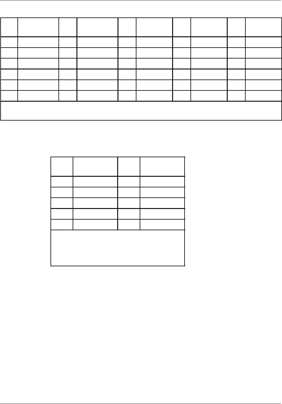
Board description Nortel Networks Confidential
2--64
PE/DCL/DD/0142
411--9001--142 Standard 15.102/EN May 2005 Copyright ©2002--2005 Nortel Networks
Pin
no.
Row E
Purpose
Pin
no.
Row D
Purpose
Pin
no.
Row C
Purpose
Pin
no.
Row B
Purpose
Pin
no.
Row A
Purpose
6GND 6 6 +48 V 6 6 -- 4 8 V
5GND 5 5 +48 V 5 5 -- 4 8 V
4GND 4 4 +48 V 4 4 -- 4 8 V
3GND 3 3 +48 V 3 3 -- 4 8 V
2GND 2 2 +48 V 2 2 -- 4 8 V
1GND 1 1 +48 V 1 1 -- 4 8 V
Legend:
GND Common logical ground
Table 2--31 Pin connections of the P13 connector (Power)
Pin
no. Purpose Pin
no. Purpose
6 1 GND
7 2 RXDBG
8 3 TXDBG
9 4 PCBUG0
5GND
Legend:
RXDBG (RS232, in) Reception Debug
TXDBG (RS232, out) Transmission Debug
PCBUG0 (TTL, in) Console presence
Table 2--32 Pin connections of the P10 connector (Debug)

Board descriptionNortel Networks Confidential 2--65
S12000 BTS Reference Manual
Copyright ©2002--2005 Nortel Networks
Pin
no. Purpose Pin
no. Purpose
1TCK 2GND
3TDO 4
5TMS 6
7 8
9TDI 10 GND
Legend:
TCK (in) ISP Programming signal
TDO (out) ISP Programming signal
TMS (in) ISP Programming signal
TDI (in) ISP Programming signal
Table 2--33 Pin connections of the P9 connector (JTAG)
Electrical characteristics
The CPCMI board is powered by a nominal --48 V DC supply.
A10 W converter on the board supplies the +5 V at a maximum level of 1 A.

Board description Nortel Networks Confidential
2--66
PE/DCL/DD/0142
411--9001--142 Standard 15.102/EN May 2005 Copyright ©2002--2005 Nortel Networks
2.7.4 CMCF board
The CBCF Module contains one or two CMCF boards. One CMCF board allows
operation in simplex mode, while two CMCF boards provide fully redundant
duplex operations.
2.7.4.1 Functional description
The CMCF Phase2 board performs the following functions:
synchronization of the BTS, through
•
selection of PCM clock
•
PCM link frequency measurement
•
input of external clock
•
generation of the reference frequency for the DRXs
•
generation of GSM Time
switching
signalling concentration
communication with the BSC and with O&M slaves (e.g. DRX, CPCMI,
RECAL)
2.7.4.2 Synchronization (SYN)
An oscillator provides the SYN function. The slave CMCF operates in a
phase--locked loop so that its H4M clock is in phase with the master CMCF. This
ensures that synchronization is maintained during a CMCF switchover.
GSM Time
The processing unit writes the GSM time (72 bits) every 60 ms and the value is
stored in the matrix at a rate of one bit per frame. Both the master and slave CMCF
re--read the information in the matrix of the master CMCF, which ensures that GSM
time is synchronized on both CMCF Phase2 boards.

Board descriptionNortel Networks Confidential 2--67
S12000 BTS Reference Manual
Copyright ©2002--2005 Nortel Networks
2.7.4.3 Physical description
The CMCF Phase2 board contains the following parts:
a master processing unit (33 MHz) that manages
•
8 Mbytes DRAM
•
4 Mbytes FLASH
•
one Ethernet link
•
one watchdog
•
32 64 Kbit/s HDLC links on one PCM
•
one RS232 test link
•
PCM switching matrix
•
one EPLD with configuration registers
•
I/O ports
a slave processing unit (33 MHz) that manages
•
one RS232 provisional link
•
32 64Kbit HDLC links on one PCM
•
one inter--CMCF 64 Kbit/s HDLC link
•
I/O ports
DC--DC converters with filters that provide 5 V, 12 V, and 3.3 V
a SYN function that synchronizes itself on one of the six signals received from
the CPCMI
a system that synchronizes the PCM clocks and switchover of both CMCF
Phase2 boards
a system that allows the synchronous transmission of GSM time on both CMCF
Phase2 boards
a system that measure the frequency of clock inputs
a 16 x 16 PCM switching matrix
a “silence” junctor to emit the A--bis silence code
a test system that allows the verification of PCM time slots
a 4--bit TEI register
an 8--bit register that encodes the position of 4 mini--switches (WD
Enable/Disable, Normal/Maintenance, etc.)
a chain switchover system

Board description Nortel Networks Confidential
2--68
PE/DCL/DD/0142
411--9001--142 Standard 15.102/EN May 2005 Copyright ©2002--2005 Nortel Networks
Electrical characteristics
The CMCF Phase2 board receives a 48 V DC power supply and generates other
required voltages from this single source.
The CMCF Phase2 board owns one DC--DC converter only to create 5 V. Thanks
to regulators, 12 V, 3.3 V and 2.5 V derive from 5 V.
The 5 V power supply is required for most CMCF components, including both
processing units. It has an 12 W power consumption. Therefore, a converter running
at 80% will dissipate about 2.5 W.
The oscillator and DAC parts of the CMCF Phase2 board require a 12 V power
supply. The oscillator consumes 1 W during maintenance and up to 10 W in its
preheating phase.
The 3.3 V power supply is used strictly for the DRAM.
Synchronization
The CMCF provides synchronization for the radio part of the BTS.
The CMCF hardware allows the selection of a clock from the following sources:
six clock signals taken from external PCM links (from the CPCMI)
CMCF master clock
The long term stability of the external PCM link clock ensures the accuracy and
stability required.
A frequency meter function on the CMCF Phase2 board measures the clocks to
determine their validity.
GSM Time channel
The SYN function generates and distributes the GSM--time channel on the Private
PCM. The GSM--time is the local BTS time, so the counters are arbitrarily set to zero
after turning on the CMCF.
The GSM time channel emission is dedicated to a special hardware system.
Synchronization between master and slave processing units
The master processing unit fully synchronizes the slave processing unit.
Fully synchronous GSM--time emission is performed through a pulse signal sent
from the Master GSM--time generation hardware system to the slave system.
External synchronization connection
An external synchronization interface is provided directly on the SYN part of the
CMCF. The software selects the synchronization origin.

Board descriptionNortel Networks Confidential 2--69
S12000 BTS Reference Manual
Copyright ©2002--2005 Nortel Networks
Front panel
The front panel of the CMCF contains the following:
a Reset button
16 LEDs
two connectors
The Reset button allows a hard reset of the board.
The front panel of the CMCF Phase2 board is shown in Figure 2--21.
LEDs
Table 2--34 describes the LEDs on the front panel of the CMCF Phase2 board.
Type LED (color) Meaning (when lit)
Board state indicators BIST (yellow) The built--in self--test is running or is stopped with
a default result.
ON (green) The board is operating and is providing a PCM
clock.
ABIS (green) The A--bis link is setup.
+5 V (green) The power is on.
RDY (green) The board is ready to become operational.
RUN (green) The applicative software is mounted.
State indicators of the external
P
C
M
l
i
k
(
A
b
i
)
OVEN (yellow) The OVCXO is in its preheating phase.
PCM link (
A
-- b i s ) LOCKED (vert) The SYN function is synchronized.
HLDVR (red) The SYN function is operating on a local clock.
CLK0 (green) Indicates the clock source.
CLK1 (green) Indicates the clock source.
CLK2 (green) Indicates the clock source.
LNK (green) The Ethernet link is established.
TX (yellow) There is a transmission on the Ethernet link.
State indicators of the external
P
C
M
l
i
k
(
A
b
i
)
COL (red) There is a collision on the Ethernet link.
PCM link (
A
-- b i s ) RX (yellow) There is a reception on the Ethernet link.
Table 2--34 LEDs on the front panel of the CMCF Phase2 Board
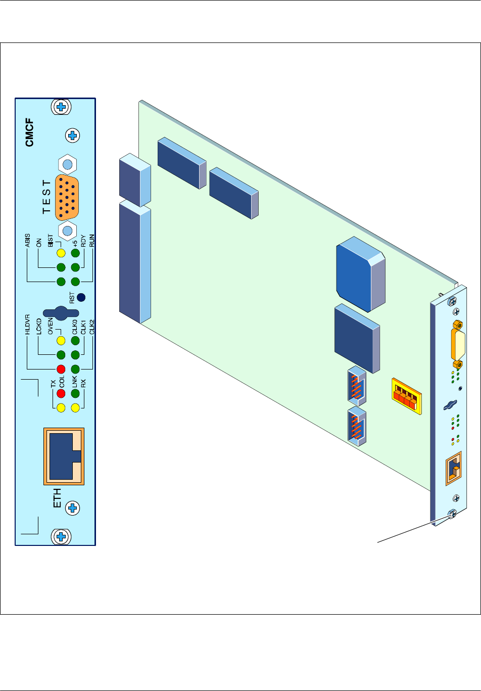
Board description Nortel Networks Confidential
2--70
PE/DCL/DD/0142
411--9001--142 Standard 15.102/EN May 2005 Copyright ©2002--2005 Nortel Networks
P3
P1
P2
Screw
J3
BDM
J4
JTAG
P4
Figure 2--21 CMCF Phase2 board

Board descriptionNortel Networks Confidential 2--71
S12000 BTS Reference Manual
Copyright ©2002--2005 Nortel Networks
2.7.4.4 Connectors
The CMCF uses eight connectors accessed from the following locations:
on the front panel (two)
inside the board (six)
The connectors are identified in Table 2--35.
Access Connector Type Purpose
Front panel TEST Sub--D 15--pin male, high density Connector used for debugging, RACE
access, BDM, test clocks, and
OCVCXO.
ETH RJ45 Connector used to connect the
Ethernet link.
Inside the
b
d
J3 BDM HE10 10--pin male
board J4 JTAG HE10 10--pin male Connector used to program the
EPLD.
P1 60--pin male Connector that plugs into the CBP.
P2 60--pin male Connector that plugs into the CBP.
P3 60--pin male Connector that plugs into the CBP.
P4 (power) 10--pin Power supply connector, which
connects to the CBP.
Table 2--35 CMCF Phase2 board connectors
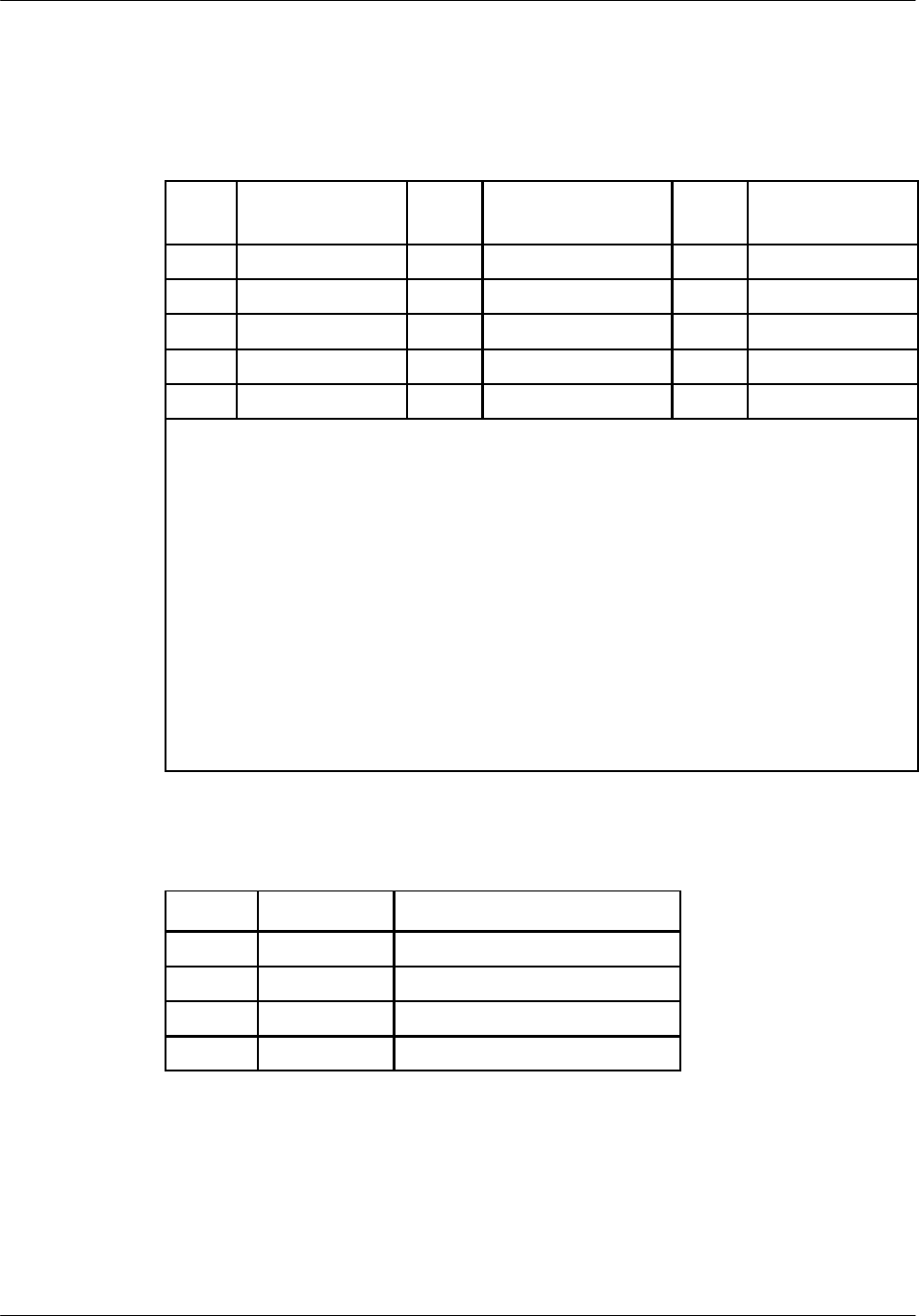
Board description Nortel Networks Confidential
2--72
PE/DCL/DD/0142
411--9001--142 Standard 15.102/EN May 2005 Copyright ©2002--2005 Nortel Networks
Pin connections
The pin connections and their significance for the CMCF connectors are identified
in Table 2--36 to Table 2--43.
Pin
no. Purpose Pin
no. Purpose Pin
no. Purpose
1NRESETH 6NDS 11 NBERR
2FREEZE 7BKPT 12 IFETCH
3GND 8IPIPE0 13 CLKREFIN
4TX 9RX 14 TCLK
5VCO 10 PRESCONS 15 H4M
Legend:
NRESETH Used for the BDM
FREEZE Used for BDM
GND Ground
TX Debug and RACE
VCO OCVCXO Voltage control
NDS Used for BDM
BKPT Used for BDM
IPIPE0 Used for debug and RACE
RX Debug (Console presence)
RX Used for BDM
PRESCONS Used for BDM
CLKREFIN Selected reference clock
TCLK PCM transmission clock
H4M Private PCM clock
Table 2--36 Pin connections of the TEST connector
Pin no. Purpose Used for
1T+ Output pair +
2T-- Output pair --
3R+ Input pair +
4R-- Input pair --
Table 2--37 Pin connections of the ETH connector
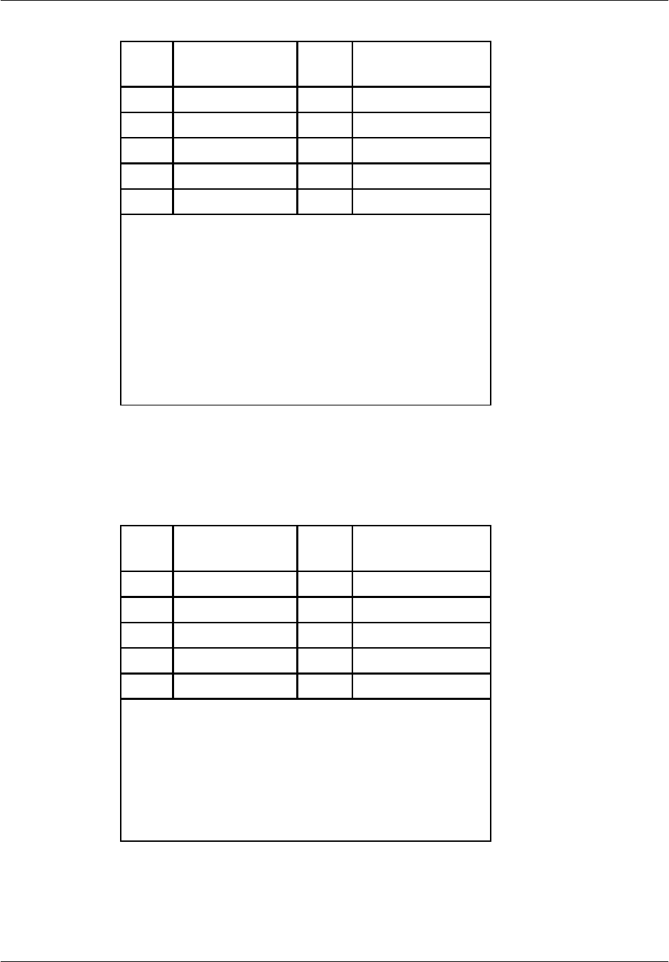
Board descriptionNortel Networks Confidential 2--73
S12000 BTS Reference Manual
Copyright ©2002--2005 Nortel Networks
Pin
no. Purpose Pin
no. Purpose
1/DS 6FREEZE
2/BERR 7/RESETH
3GND 8DSI
4/BKP 9NC
5GND 10 DSO
Legend:
/DS Data strobe I/O Input
/BERR Bus error output signal
GND Electrical ground
/BKP Clock output signal
GND Electrical ground
FREEZE Break point acknowledge output signal
/RESETH Reset IO signal
DSI Serial data input signal
NC Not connected
DSO Serial data output signal
Table 2--38 Pin connections of the J3 (BDM) connector
Pin
no. Purpose Pin
no. Purpose
1TCK 6
2GND 7Reset
3TDO 8
4VCC 9Data in
5TMS 10 Ground
Legend:
TCK Clock
GND Ground
TDO Data out
VCC Power supply
TMS Selection
TRST Reset
TDI Data in
Table 2--39 Pin connections of the J4 (JTAG) Connector
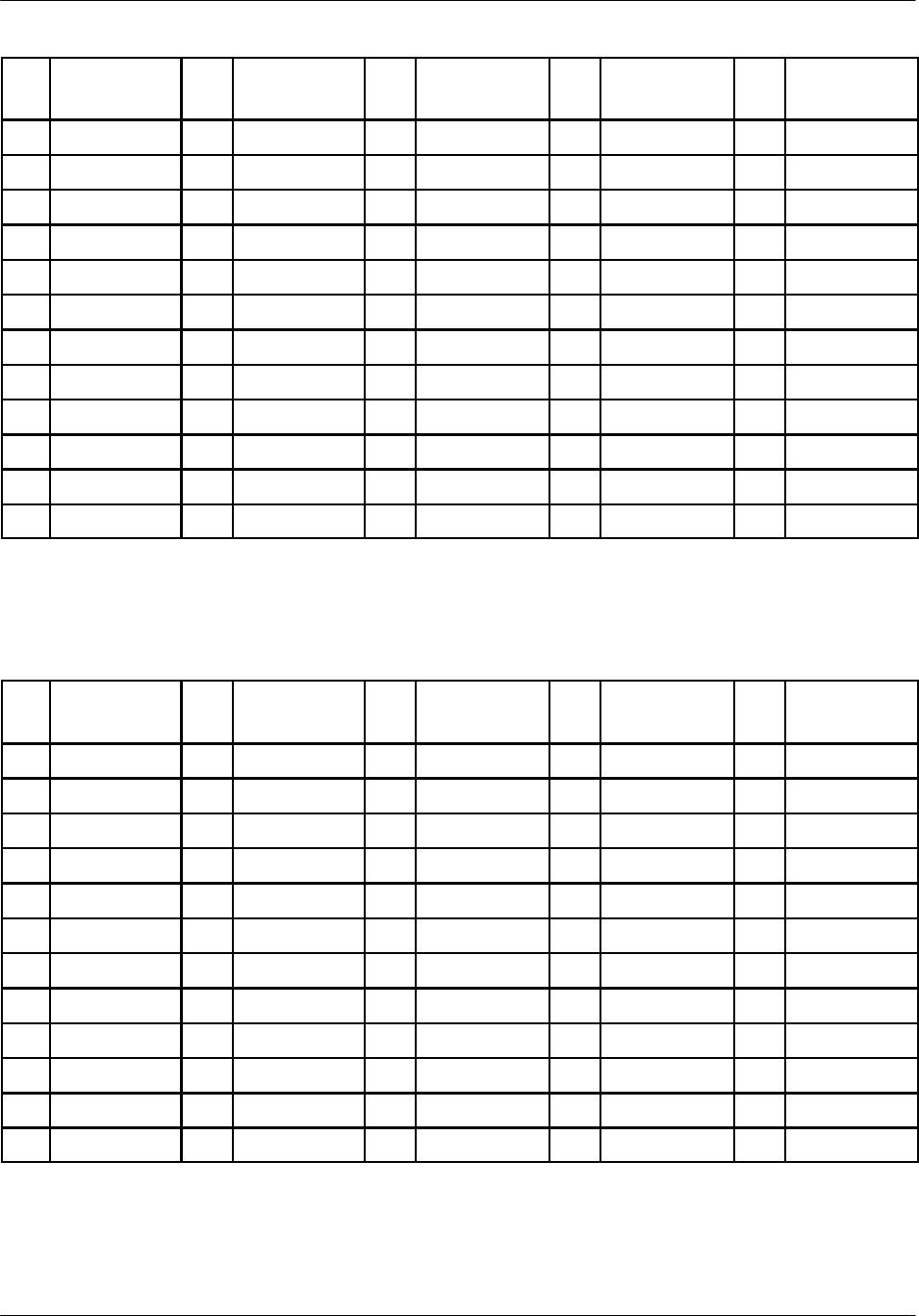
Board description Nortel Networks Confidential
2--74
PE/DCL/DD/0142
411--9001--142 Standard 15.102/EN May 2005 Copyright ©2002--2005 Nortel Networks
Pin
no.
Row A
Purpose
Pin
no.
Row B
Purpose
Pin
no.
Row C
Purpose
Pin
no.
Row D
Purpose
Pin
no.
Row E
Purpose
12 GND 12 GND 12 GND 12 GND 12 GND
11 RS232TX 11 11 P5 V 11 11 RS232RX
10 RS232SP1 10 RS232SP2 10 E1T1 10 RS232SP3 10 RE232SP4
9 9 9 GND 9 9
8GPSCLK 8NGPSCLK 8GND 8 8
7PSYT00 7NSYT00 7TCLK 7CONFIG00 7NCONFIG00
6PSYT10 6NSYT10 6NTCLK 6CONFIG10 6NCONFIG10
5PSYT01 5NSYT01 5SY 5CONFIG01 5NCONFIG01
4PSYT11 4NSYT11 4NSY 4CONFIG11 4NCONFIG11
3PSYT02 3NSYT02 3H4M 3CONFIG02 3NCONFIG02
2PSYT12 2NSYT12 2NH4M 2CONFIG12 2NCONFIG12
1PLUG2 1GND 1GND 1GND 1PLUG3
Table 2--40 Pin connections of the P1 connector
Pin
no.
Row A
Purpose
Pin
no.
Row B
Purpose
Pin
no.
Row C
Purpose
Pin
no.
Row D
Purpose
Pin
no.
Row E
Purpose
12 MICE0 12 NMICE0 12 SY0 12 MICR0 12 NMICR0
11 MICE1 11 NMICE1 11 NSY0 11 MICR1 11 NMICR1
10 MICE2 10 NMICE2 10 H4M0 10 MICR2 10 NMICR2
9MICE3 9NMICE3 9NH4M0 9MICR3 9NMICR3
8MICE4 8NMICE4 8SY1 8MICR4 8NMICR4
7MICE5 7NMICE5 7NSY1 7MICR5 7NMICR5
6MICE6 6NMICE6 6H4M1 6MICR6 6NMICR6
5MICE7 5NMICE7 5NH4M1 5MICR7 5NMICR7
4MICE8 4NMICE8 4SY2 4MICR8 4NMICR8
3MICE9 3NMICE9 3NSY2 3MICR9 3NMICR9
2MICE10 2NMICE10 2H4M2 2MICR10 2NMICR10
1MICE11 1NMICE11 1NH4M2 1MICR11 1NMICR11
Table 2--41 Pin connections of the P2 connector
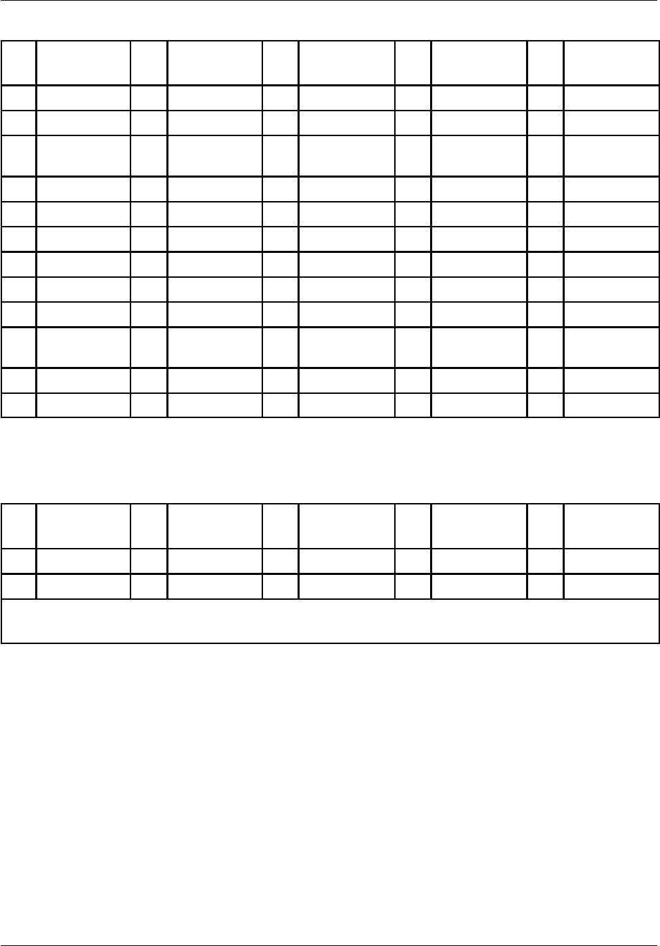
Board descriptionNortel Networks Confidential 2--75
S12000 BTS Reference Manual
Copyright ©2002--2005 Nortel Networks
Pin
no.
Row A
Purpose
Pin
no.
Row B
Purpose
Pin
no.
Row C
Purpose
Pin
no.
Row D
Purpose
Pin
no.
Row E
Purpose
12 PLUG0 12 GND 12 GND 12 GND 12 PLUG1
11 SCOUT 11 11 SCIN 11 11 CMCFOUT
10 NSCOUT 10 10 NSCIN 10 10 NCMCFOU
T
9GND 9GND 9CMCFIN 9GND 9GND
8RXD 8NRXD 8NCMCFIN 8RXCLK 8NRXCLK
7TXD 7NTXD 7 7 TXCLK 7NTXCLK
6 6 6 6 6
5 5 5 5 5
4GSMIN 4NGSMIN 4 4 GSMOUT 4NGSMOUT
3GSMSYIN 3NGSMSYIN 3GND 3GSMSYOU
T
3 NGSMSYO
UT
2TWI0 2TEI1 2AOUB 2TEI2 2TEI3
1GND 1GND 1GND 1GND 1GND
Table 2--42 Pin connections of the P3 connector
Pin
no.
Row A
Purpose
Pin
no.
Row B
Purpose
Pin
no.
Row C
Purpose
Pin
no.
Row D
Purpose
Pin
no.
Row E
Purpose
1GND 1 1 0V 1 1 -- 4 8 V
2GND 2 2 0V 2 2 -- 4 8 V
Legend:
GND Common logical ground
Table 2--43 Pin connections of the P4 (Power) connector
2.7.4.5 Electrical characteristics
The CMCF is powered by a nominal dc --48 V power supply. The acceptable range
is from 36 V to 72 V.
The maximum power consumption of the board is 0.7 A.

Board description Nortel Networks Confidential
2--76
PE/DCL/DD/0142
411--9001--142 Standard 15.102/EN May 2005 Copyright ©2002--2005 Nortel Networks
2.7.5 BCFICO board
2.7.5.1 Functional description
The BCFICO board allows the reception and transmission of external signals
towards the CMCF and CPCMI boards.
The coding of TEI signals can be set using the switched pull--down resistor inside
the BCFICO board.
2.7.5.2 Physical description
The BCFICO contains the following:
six connectors on the front panel
four connectors inside the board
one switch register inside the board
The BCFICO board is shown in Figure 2--22.
The connectors are identified in Table 2--44 and the register is described in the
Section “Switch register”.
Access Connector Type Purpose
Front panel PCM0/1 Sub--D, 25--pin female Connectors used for Private PCM links 0 and
1. Connected to J8 on the inside of the
board.
PCM2/3 Sub--D, 25--pin female Connectors used for Private PCM links 2 and
3. Connected to J8 on the inside of the
board
PCM4/5 Sub--D, 25--pin female Connectors used for Private PCM links 4 and
5. Connected to J5 on the inside of the
board
ABIS Sub--D 25--pin male Connected to J5 on the inside of the board.
PWR Sub--D, 3--pin male +48 V dc power supply connector.
Connected to the J3 connector on the inside
of the board.
RS232 Sub--D, 9--pin male Connected to the J1 connector on the inside
of the board.
Inside the
board
J2 10--pin female Power supply connector, which is plugged
into the CBP.
J4 60--pin female Connecter that is plugged into the CBP.
J6 60--pin female Connecter that is plugged into the CBP.
J7 60--pin female Connecter that is plugged into the CBP.
Table 2--44 BCFICO board connectors
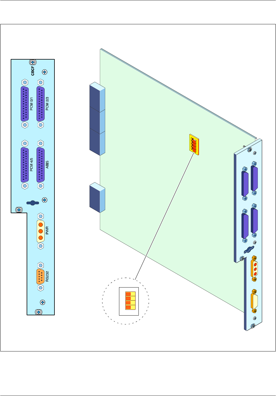
Board descriptionNortel Networks Confidential 2--77
S12000 BTS Reference Manual
Copyright ©2002--2005 Nortel Networks
J2
J7
J6
J4
2
3
4
TEI0
1
ON
TEI1
TEI2
TEI3
S1
10
Figure 2--22 BCFICO board

Board description Nortel Networks Confidential
2--78
PE/DCL/DD/0142
411--9001--142 Standard 15.102/EN May 2005 Copyright ©2002--2005 Nortel Networks
2.7.5.3 Pin connections
The pin connections of the BCFICO connectors are identified in Table 2--45 to
Table 2--54.
Pin
no. Purpose Pin
no. Purpose
1SEL4 14 NSEL4
2SEL5 15 NSEL5
3SEL6 16 NSEL6
4SEL7 17 NSEL7
5GND 18 GND
6GND 19 GND
7MICE0 20 NMICE0
8MICE1 21 NMICE1
9MICR0 22 NMICR0
10 MICR1 23 NMICR1
11 PH40 24 NH40
12 PSY0 25 NSY0
13 GND
Table 2--45 PCM0/1 pin connections

Board descriptionNortel Networks Confidential 2--79
S12000 BTS Reference Manual
Copyright ©2002--2005 Nortel Networks
Pin
no. Purpose Pin
no. Purpose
1SEL14 14 NSEL14
2SEL15 15 NSEL15
3SEL16 16 NSEL16
4SEL17 17 NSEL17
5GND 18 GND
6GND 19 GND
7MICE2 20 NMICE2
8MICE3 21 NMICE3
9MICR2 22 NMICR2
10 MICR3 23 NMICR3
11 PH41 24 NH41
12 PSY1 25 NSY1
13 GND
Table 2--46 PCM2/3 pin connections
Pin
no. Purpose Pin
no. Purpose
1SEL24 14 NSEL24
2SEL25 15 NSEL25
3SEL26 16 NSEL26
4SEL27 17 NSEL27
5GND 18 GND
6GND 19 GND
7MICE4 20 NMICE4
8MICE5 21 NMICE5
9MICR4 22 NMICR4
10 MICR5 23 NMICR5
11 PH42 24 NH42
12 PSY2 25 NSY2
13 GND
Table 2--47 PCM4/5 pin connections
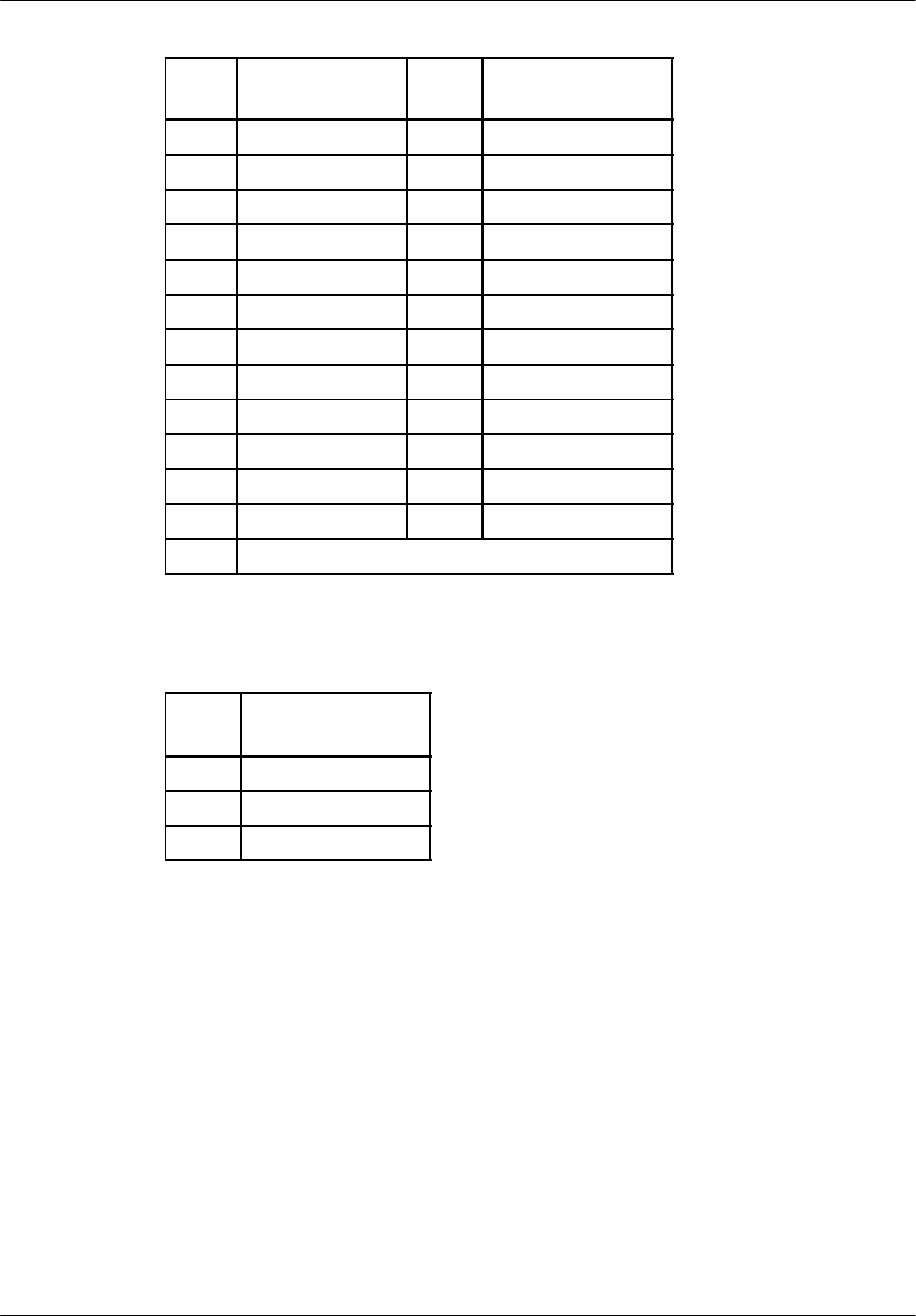
Board description Nortel Networks Confidential
2--80
PE/DCL/DD/0142
411--9001--142 Standard 15.102/EN May 2005 Copyright ©2002--2005 Nortel Networks
Pin
no. Purpose Pin
no. Purpose
1EHDB0 14 EHDB3
2NEHDB0 15 NEHDB3
3RHDB0 16 RHDB3
4NRHDB0 17 NRHDB3
5EHDB1 18 EHDB4
6NEHDB1 19 NEHDB4
7RHDB1 20 RHDB4
8NRHDB1 21 NRHDB4
9EHDB2 22 EHDB5
10 NEHDB2 23 NEHDB5
11 RHDB2 24 RHDB5
12 NRHDB2 25 NRHDB5
13
Table 2--48 ABIS pin connections
Pin
no. Purpose
1(--)48 V
2GND
3(+)48 V
Table 2--49 PWR pin connections

Board descriptionNortel Networks Confidential 2--81
S12000 BTS Reference Manual
Copyright ©2002--2005 Nortel Networks
Pin
no. Purpose
1RS232SP2
2RS232RX
3RS232TX
4RS232SP1
5GND
6RS232SP3
7RS232SP4
8GPSCLK
9NGPSCLK
Table 2--50 RS232 pin connections
A B C D E
1(--)48 V (+)48 V GND
2(--)48 V (+)48 V GND
3(--)48 V (+)48 V GND
4(--)48 V (+)48 V GND
5(--)48 V (+)48 V GND
6(--)48 V (+)48 V GND
Table 2--51 J2 pin connections

Board description Nortel Networks Confidential
2--82
PE/DCL/DD/0142
411--9001--142 Standard 15.102/EN May 2005 Copyright ©2002--2005 Nortel Networks
A B C D E
12
11 NRHDB1 RHDB1 NRHDB0 RHDB0
10
9NEHDB1 EHDB1 NEHDB0 EHDB0
8
7NRHDB3 RHDB3 NRHDB2 RHDB2
6
5NEHDB3 EHDB3 NEHDB2 EHDB2
4
3NRHDB5 RHDB5 NRHDB4 RHDB4
2
1NEHDB5 EHDB5 NEHDB4 EHDB4
Table 2--52 J4 pin connections
A B C D E
12 GND GND +5 V GND GND
11 RS232RX RS232SP3 GND RS232SP2 RS232TX
10 RS232SP4 NGPSCLK GND GPSCLK RS232SP1
9TEI3 TEI2 TEI1 TEI0 TEI20
8TEI00 TEI01 NAOUB TEI11
7GND GND GND NHLOC HLOC
6NCONFIG00 CONFIG00 TCLK NSYT00 PSYT00
5NCONFIG10 CONFIG10 NTCLK NSYT10 PSYT10
4NCONFIG01 CONFIG01 PSY NSYT01 PSYT01
3NCONFIG11 CONFIG11 NSY NSYT11 PSYT11
2NCONFIG02 CONFIG02 PH4 NSYT02 PSYT02
1NCONFIG12 CONFIG12 NH4 NSYT12 PSYT12
Table 2--53 J6 pin connections

Board descriptionNortel Networks Confidential 2--83
S12000 BTS Reference Manual
Copyright ©2002--2005 Nortel Networks
A B C D E
12 NMICR0 MICR0 PSY0 NMICE0 MICE0
11 NMICR1 MICR1 NSY0 NMICE1 MICE1
10 NMICR2 MICR2 PH40 NMICE2 MICE2
9NMICR3 MICR3 NH40 NMICE3 MICE3
8NMICR4 MICR4 PSY1 NMICE4 MICE4
7NMICR5 MICR5 NSY1 NMICE5 MICE5
6PH41 NMICE6 MICE6
5NH41 NMICE7 MICE7
4PSY2 NMICE8 MICE8
3NSY2 NMICE9 MICE9
2PH42 NMICE10 MICE10
1NH42 NMICE11 MICE11
Table 2--54 J7 pin connections

Board description Nortel Networks Confidential
2--84
PE/DCL/DD/0142
411--9001--142 Standard 15.102/EN May 2005 Copyright ©2002--2005 Nortel Networks
2.7.5.4 Switch resistor
The TEI signals can be configured by setting the switch pull--down register inside
inside the BCFICO in the positions indicated in Table 2--55.
Signal
name Link Connector pin termination Logical
code
TEI00
TEI01
to CPCMI0
to CPCMI0
grounded on CBP
grounded on CBP
0
0
TEI10
TEI11
to CPCMI1
to CPCMI1
left unconnected
grounded on CBP
1
0
TEI20
TEI21
to CPCMI2
to CPCMI2
grounded on CBP
left unconnected
0
1
TEI0
TEI1
TEI2
TEI3
to2CMCF
to2CMCF
to2CMCF
to2CMCF
pull--down serial mounted with a switch on
BCFICO
pull--down serial mounted with a switch on
BCFICO
pull--down serial mounted with a switch on
BCFICO
pull--down serial mounted with a switch on
BCFICO
0or1
0or1
0or1
0or1
AOUB
NAOUB
to CMCF_A
to CMCF_B
left unconnected.
grounded on CBP
1
0
Table 2--55 TEI Resistor coding on the switch register

Board descriptionNortel Networks Confidential 2--85
S12000 BTS Reference Manual
Copyright ©2002--2005 Nortel Networks
2.7.5.5 TEI configuration
WIth the TEI0 to TEI3 (S1) switches of the CBCICO board (voir Figure 2--22) you
can update the TEI configuration as described in the following table :
TEI number TEI0
switch
TEI1
switch
TEI2
switch
TEI3
switch
01 1 1 1
11 1 1 0
21 1 0 1
31 1 0 0
41 0 1 1
51 0 1 0
61 0 0 1
71 0 0 0
80 1 1 1
90 1 1 0
10 0 1 0 1
11 0 1 0 0
12 0 0 1 1
13 0 0 1 0
14 0 0 0 1
15 0 0 0 0
Key:
0 : Indicates that the switch is in the “ON“ position
1 : Indicates that the switch is in the “OFF“ position
Note: The gray line indicates the factory setting.
Table 2--56 TEI configuration

Board description Nortel Networks Confidential
2--86
PE/DCL/DD/0142
411--9001--142 Standard 15.102/EN May 2005 Copyright ©2002--2005 Nortel Networks
2.7.5.6 Interfaces specifications
The 48 V power supply is connected to the MAINICO board via power terminals.
screw:
M1 Mechanical ground connected to the DRXs PUPS output ground.
M2 --48 V supply
M3 0 V supply
each 48 V DRX Power connector is protected by a 2A fuse.
2.7.6 CBCF Back Panel (CBP)
2.7.6.1 Functional description
The CBCF Back Panel (CBP) provides the interconnection between the following
CBCF Module boards:
two CMCFs
three CPCMIs
one BCFICO
2.7.6.2 Physical description
The CBP contains the following six connectors:
two CMCF signal connectors
•
CMCF_A
•
CMCF_B
three CPCMI signal connectors
•
CPCMI_0
•
CPCMI_1
•
CPCMI_2
one BCFICO connector
The CBP board and its connectors are shown in Figure 2--23.
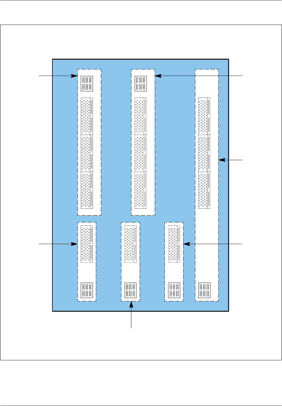
Board descriptionNortel Networks Confidential 2--87
S12000 BTS Reference Manual
Copyright ©2002--2005 Nortel Networks
SIGN1C
SIGN2C
SIGN1B
SIGN2B
SIGN1A
SIGN2A
AL1
AL2
AL3
AL4
AL5
AL6
SIGN6ASIGN6BSIGN6C
ABCDE
CMCF_B
connectors
BCFICO
connectors
CPCMI_2
connectors
CMCF_A
connectors
CPCMI_0
connectors
CPCMI_1
connectors
ACE ACE
ABCDE ABCDE ABCDE
ACEACE ACE ACE
ABCDE ABCDE ABCDE
SIGN3 SIGN4 SIGN5
Figure 2--23 CBP board

Board description Nortel Networks Confidential
2--88
PE/DCL/DD/0142
411--9001--142 Standard 15.102/EN May 2005 Copyright ©2002--2005 Nortel Networks
2.7.6.3 Pin connections
The pin connections of the CBP connectors are identified in Table 2--57 to
Table 2--69.
A B C D E
12 PLUGA0 GND GND GND PLUGA0
11 CMCFAB SCBA SCAB
10 NCMCFAB NSCBA NSCAB
9GND GND CMCFBA GND GND
8NCLKBA CLKBA NCMCFBA NDATBA DATBA
7NCLKAB CLKAB NDATAB DATAB
6
5
4NGSMAB GSMAB NGSMBA GSMBA
3NGSMSYAB GSMSYAB GND NGSMSYBA GSMSYBA
2TEI3 TEI2 AOUB TEI1 TEI0
1GND GND GND GND GND
Table 2--57 CMCF_A (Sign1A) pin connections

Board descriptionNortel Networks Confidential 2--89
S12000 BTS Reference Manual
Copyright ©2002--2005 Nortel Networks
A B C D E
12 NMICR0 MICR0 PSY0 NMICE0 MICE0
11 NMICR1 MICR1 NSY0 NMICE1 MICE1
10 NMICR2 MICR2 PH40 NMICE2 MICE2
9NMICR3 MICR3 NH40 NMICE3 MICE3
8NMICR4 MICR4 PSY1 NMICE4 MICE4
7NMICR5 MICR5 NSY1 NMICE5 MICE5
6NMICR6 MICR6 PH41 NMICE6 MICE6
5NMICR7 MICR7 NH41 NMICE7 MICE7
4NMICR8 MICR8 PSY2 NMICE8 MICE8
3NMICR9 MICR9 NSY2 NMICE9 MICE9
2NMICR10 MICR10 PH42 NMICE10 MICE10
1NMICR11 MICR11 NH42 NMICE11 MICE11
Table 2--58 CMCF_A (Sign1B) pin connections
A B C D E
12 GND GND GND GND GND
11 RS232RX +5 V RS232TX
10 RS232SP4 RS232SP3 E1T1 RS232SP2 RS232SP1
9HLOC
8NHLOC NGPSCLK GPSCLK
7NCONFIG00 CONFIG00 TCLK NSYT00 PSYT00
6NCONFIG10 CONFIG10 NTCLK NSYT10 PSYT10
5NCONFIG01 CONFIG01 PSY NSYT01 PSYT01
4NCONFIG11 CONFIG11 NSY NSYT11 PSYT11
3NCONFIG02 CONFIG02 PH4 NSYT02 PSYT02
2NCONFIG12 CONFIG12 NH4 NSYT12 PSYT12
1PLUGA1 GND GND GND PLUGA1
Table 2--59 CMCF_A (Sign1C) pin connections

Board description Nortel Networks Confidential
2--90
PE/DCL/DD/0142
411--9001--142 Standard 15.102/EN May 2005 Copyright ©2002--2005 Nortel Networks
A B C D E
12 PLUGB0 GND GND GND PLUGB0
11 CMCFBA SCAB SCBA
10 NCMCFBA NSCAB NSCBA
9GND GND CMCFAB GND GND
8NCLKAB CLKAB NCMCFAB NDATAB DATAB
7NCLKBA CLKBA NDATBA DATBA
6
5
4NGSMBA GSMBA NGSMAB GSMAB
3NGSMSYBA GSMSYBA GND NGSMSYAB GSMSYAB
2TEI3 TEI2 NAOUB TEI1 TEI0
1GND GND GND GND GND
Table 2--60 CMCF_B (Sign2A) pin connections
A B C D E
12 NMICR0 MICR0 PSY0 NMICE0 MICE0
11 NMICR1 MICR1 NSY0 NMICE1 MICE1
10 NMICR2 MICR2 PH40 NMICE2 MICE2
9NMICR3 MICR3 NH40 NMICE3 MICE3
8NMICR4 MICR4 PSY1 NMICE4 MICE4
7NMICR5 MICR5 NSY1 NMICE5 MICE5
6NMICR6 MICR6 PH41 NMICE6 MICE6
5NMICR7 MICR7 NH41 NMICE7 MICE7
4NMICR8 MICR8 PSY2 NMICE8 MICE8
3NMICR9 MICR9 NSY2 NMICE9 MICE9
2NMICR10 MICR10 PH42 NMICE10 MICE10
1NMICR11 MICR11 NH42 NMICE11 MICE11
Table 2--61 CMCF_B (Sign2B) pin connections

Board descriptionNortel Networks Confidential 2--91
S12000 BTS Reference Manual
Copyright ©2002--2005 Nortel Networks
A B C D E
12 GND GND GND GND GND
11 RS232RX +5 V RS232TX
10 RS232SP4 RS232SP3 E1T1 RS232SP2 RS232SP1
9HLOC
8NHLOC NGPSCLK GPSCLK
7NCONFIG00 CONFIG00 TCLK NSYT00 PSYT00
6NCONFIG10 CONFIG10 NTCLK NSYT10 PSYT10
5NCONFIG01 CONFIG01 PSY NSYT01 PSYT01
4NCONFIG11 CONFIG11 NSY NSYT11 PSYT11
3NCONFIG02 CONFIG02 PH4 NSYT02 PSYT02
2NCONFIG12 CONFIG12 NH4 NSYT12 PSYT12
1PLUGB1 GND GND GND PLUGB1
Table 2--62 CMCF_B (Sign2C) pin connections
A B C D E
1NEHDB1 EHDB1 NEHDB0 EHDB0
2
3NRHDB1 RHDB1 NRHDB0 RHDB0
4
5GND GND GND GND GND
6TEI01 TEI00 E1T1 NCONFIG10 NCONFIG00
7CONFIG10 CONFIG00
8NTCLK NSYT10 NSYT00
9TCLK PSYT10 PSYT00 NHLOC NSY
10 HLOC PSY
11 NMICR7 NMICE7 NMICR6 NMICE6 NH4
12 MICR7 MICE7 MICR6 MICE6 PH4
Table 2--63 CPCMI_0 (Sign3) pin connections

Board description Nortel Networks Confidential
2--92
PE/DCL/DD/0142
411--9001--142 Standard 15.102/EN May 2005 Copyright ©2002--2005 Nortel Networks
A B C D E
1NEHDB3 EHDB3 NEHDB2 EHDB2
2
3NRHDB3 RHDB3 NRHDB2 RHDB2
4
5GND GND GND GND GND
6TEI11 TEI10 E1T1 NCONFIG11 NCONFIG01
7CONFIG11 CONFIG01
8NTCLK NSYT11 NSYT01
9TCLK PSYT11 PSYT01 NHLOC NSY
10 HLOC PSY
11 NMICR9 NMICE9 NMICR8 NMICE8 NH4
12 MICR9 MICE9 MICR8 MICE8 PH4
Table 2--64 CPCMI_1 (Sign 4) pin connections
A B C D E
1NEHDB5 EHDB5 NEHDB4 EHDB4
2
3NRHDB5 RHDB5 NRHDB4 RHDB4
4
5GND GND GND GND GND
6TEI21 TEI20 E1T1 NCONFIG12 NCONFIG02
7CONFIG12 CONFIG02
8NTCLK NSYT12 NSYT02
9TCLK PSYT12 PSYT02 NHLOC NSY
10 HLOC PSY
11 NMICR11 NMICE11 NMICR10 NMICE10 NH4
12 MICR11 MICE11 MICR10 MICE10 PH4
Table 2--65 CPCMI_2 (Sign 5) pin connections

Board descriptionNortel Networks Confidential 2--93
S12000 BTS Reference Manual
Copyright ©2002--2005 Nortel Networks
A B C D E
12 NMICR0 MICR0 PSY0 NMICE0 MICE0
11 NMICR1 MICR1 NSY0 NMICE1 MICE1
10 NMICR2 MICR2 PH40 NMICE2 MICE2
9NMICR3 MICR3 NH40 NMICE3 MICE3
8NMICR4 MICR4 PSY1 NMICE4 MICE4
7NMICR5 MICR5 NSY1 NMICE5 MICE5
6PH41 NMICE6 MICE6
5NH41 NMICE7 MICE7
4PSY2 NMICE8 MICE8
3NSY2 NMICE9 MICE9
2PH42 NMICE10 MICE10
1NH42 NMICE11 MICE11
Table 2--66 BCFICO (Sign6A) pin connections
A B C D E
12 GND GND +5 V GND GND
11 RS232RX RS232SP3 GND RS232SP2 RS232TX
10 RS232SP4 NGPSCLK GND GPSCLK RS232SP1
9TEI3 TEI2 TEI1 TEI0 TEI20
8TEI00 TEI01 NAOUB TEI11
7GND GND GND NHLOC HLOC
6NCONFIG00 CONFIG00 TCLK NSYT00 PSYT00
5NCONFIG10 CONFIG10 NTCLK NSYT10 PSYT10
4NCONFIG01 CONFIG01 PSY NSYT01 PSYT01
3NCONFIG11 CONFIG11 NSY NSYT11 PSYT11
2NCONFIG02 CONFIG02 PH4 NSYT02 PSYT02
1NCONFIG12 CONFIG12 NH4 NSYT12 PSYT12
Table 2--67 BCFICO (Sign6B) pin connections

Board description Nortel Networks Confidential
2--94
PE/DCL/DD/0142
411--9001--142 Standard 15.102/EN May 2005 Copyright ©2002--2005 Nortel Networks
A B C D E
12
11 NRHDB1 RHDB1 NRHDB0 RHDB0
10
9NEHDB1 EHDB1 NEHDB0 EHDB0
8
7NRHDB3 RHDB3 NRHDB2 RHDB2
6
5NEHDB3 EHDB3 NEHDB2 EHDB2
4
3NRHDB5 RHDB5 NRHDB4 RHDB4
2
1NEHDB5 EHDB5 NEHDB4 EHDB4
Table 2--68 BCFICO (Sign6C) pin connections
A B C D E
1-- 4 8 V +48 V GND
2-- 4 8 V +48 V GND
3-- 4 8 V +48 V GND
4-- 4 8 V +48 V GND
5-- 4 8 V +48 V GND
6-- 4 8 V +48 V GND
Table 2--69 AL1, AL2, AL3, AL4, AL5, AL6 pin connections
(Power voltage connectors)

Board descriptionNortel Networks Confidential 2--95
S12000 BTS Reference Manual
Copyright ©2002--2005 Nortel Networks
2.8 DRX, e--DRX, or DRX--ND3 module
The module processes reception and transmission signals. It has a receive sensitivity
of --110 dBm or --108 dBm.
2.8.1 DRX front panel
The DRX front panel has the following elements (see Figure 2--24):
a 26--pin power supply connector (PWR)
a 66--pin connector for the private PCM (FH--PCM)
a 50--pin test connector (TEST)
a transmission signal output (TX OUT)
a diversity reception signal input (RXD IN)
a main reception signal input (RXM IN)
12 LEDs:
•
+5 V: Power supply
•
RES1: (Reserved)
•
ALA: Alarm
•
DRX: DRX general status
•
AMNU: AMNU status
•
SPU: SPU or RX status
•
BDT: BDT status
•
TX: TX status
•
LI: Ethernet connection OK
•
CL: Ethernet collision
•
TX: Ethernet transmission
•
RX: Ethernet reception
The LEDs for the AMNU, SPU, BDT, and TX can be in flashing mode while the
corresponding software is being downloaded.
For further information about the status of LEDs, refer to the document “S12000
BTS Maintenance Manual -- Procedures”.
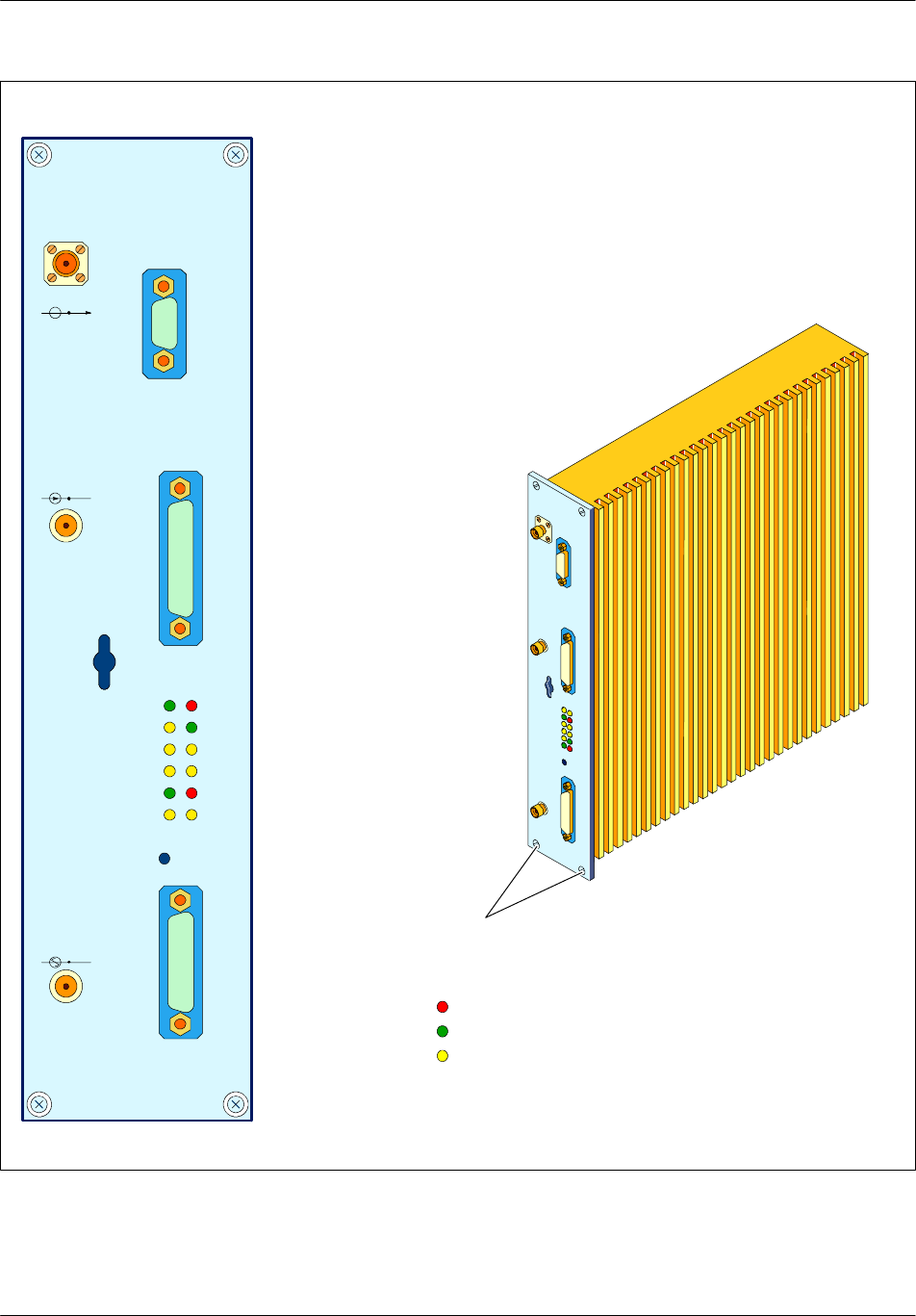
Board description Nortel Networks Confidential
2--96
PE/DCL/DD/0142
411--9001--142 Standard 15.102/EN May 2005 Copyright ©2002--2005 Nortel Networks
ALA
DRX
SPU
TX
CL
RX
+5V
RES1
AMNU
BDT
LI
TX
RESET
TEST
FH--PCM
PWR
TX OUT
RXD IN
RXM IN
Legend : Red LED
Green LED
Yellow LED
Screws
Figure 2--24 DRX module

Board descriptionNortel Networks Confidential 2--97
S12000 BTS Reference Manual
Copyright ©2002--2005 Nortel Networks
2.8.2 e--DRX front panel
The e--DRX front panel has the following elements (see Figure 2--25):
a 26--pin power supply connector (PWR)
a 66--pin connector for the private PCM (FH--PCM)
a 50--pin test connector (TEST)
a transmission signal output (TX)
a diversity reception signal input (RXD IN)
a main reception signal input (RXM IN)
8 LEDs:
•
FWR: TBD
•
SPU: SPU status
•
e--DRX: e--DRX general status
•
ALA: Alarm
•
BIST: Built--In Self Status
•
LI: Ethernet connection OK
•
TX: Ethernet transmission
•
RX: Ethernet reception
1 button:
•
RESET: restart the module
For further information about the status of LEDs, refer to NTP < 144 >.
For more details about DRX and e--DRX architectures, please see chapters 3.3
and 3.4.
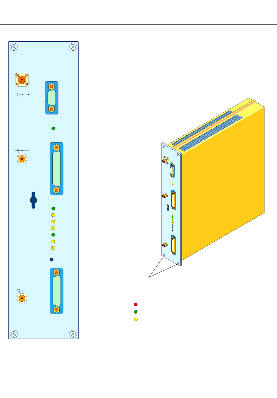
Board description Nortel Networks Confidential
2--98
PE/DCL/DD/0142
411--9001--142 Standard 15.102/EN May 2005 Copyright ©2002--2005 Nortel Networks
SPU
DRX
ALA
BIST
LI
TX
RESET
TEST
FH--PCM
PWR
TX OUT
RXD IN
RXM IN
Legend : Red LED
Green LED
Yellow LED
Screws
RX
FWR
Figure 2--25 e--DRX module

Board descriptionNortel Networks Confidential 2--99
S12000 BTS Reference Manual
Copyright ©2002--2005 Nortel Networks
2.9 RX--splitter
The RX--splitter amplifies a reception signal and splits it into several signals that
it sends to the receivers.
2.9.1 Principle
The RX--splitter exists in two types: 1x4 and 2x2. It consists of the following
elements according to the type :
Type 1x4: a two--stage, four--channel splitter (see Figure 2--26), which splits the
signal from the LNA--splitter into four identical signals.
Type 2x2: a two--stage, two two--channels splitter (see Figure 2--27), which
splits each of two signals from the LNA--splitter into two identical signals.
Four Low--Noise Amplifiers (LNA), which amplify one channel each.
Four resistive attenuators, which adjust the gain to the required value on each
LNA channel.
A remote amplifier, which controls the power of the incoming signal. The DRX
supervises the amplifier and sends the information to the BSC.
Each channel of the RX--splitter is connected to a different receiver. The receiver
supplies the LNA of the channel to which it is connected by means of the RF cable.
The four channels are therefore supplied independently of one another.
Channels which are not connected to any receiver are not supplied with power, and
so need not be adapted by a 50 Ωtermination.
Nominal gain on the four outputs is + 9.2 dBm (GSM 850), + 8 dBm (GSM 1900).
2.9.2 Consumption
The RX--splitter is supplied with +12 V dc + 5% or +5.5 V dc + 5% (GSM 1900).
Its maximum consumption is 40 mA (GSM 1900) 50 mA for GSM 850. The
receivers to which it is connected trip an alarm if this limit is exceeded.
2.9.3 RX--splitter front panel
The front panel of the RX--splitter has the following elements (see Figure 2--28):
Four RX connectors each supply a signal to a receiver which supplies them with
voltage.
An IN connector is used by the RX--splitter to receive the reception signal.
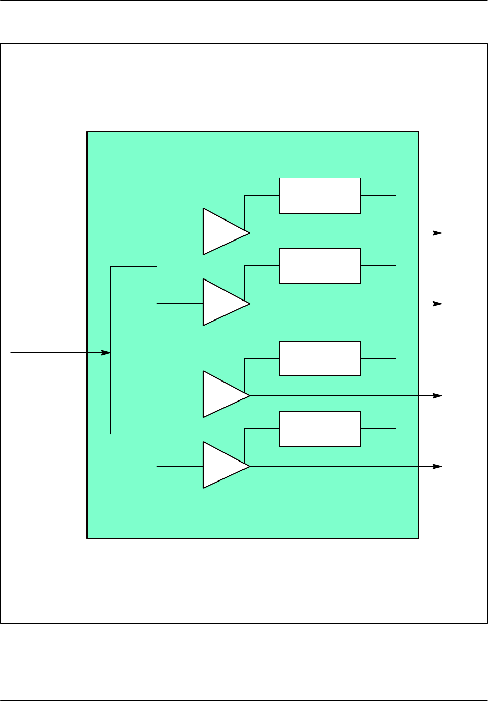
Board description Nortel Networks Confidential
2--100
PE/DCL/DD/0142
411--9001--142 Standard 15.102/EN May 2005 Copyright ©2002--2005 Nortel Networks
RX--splitter
RX0
LNA
RF combiner
RX1
RX2
RX3
LNA
LNA
LNA
Power supply
regulation
Power supply
regulation
Power supply
regulation
Power supply
regulation
Figure 2--26 RX--splitter diagram type 1x4
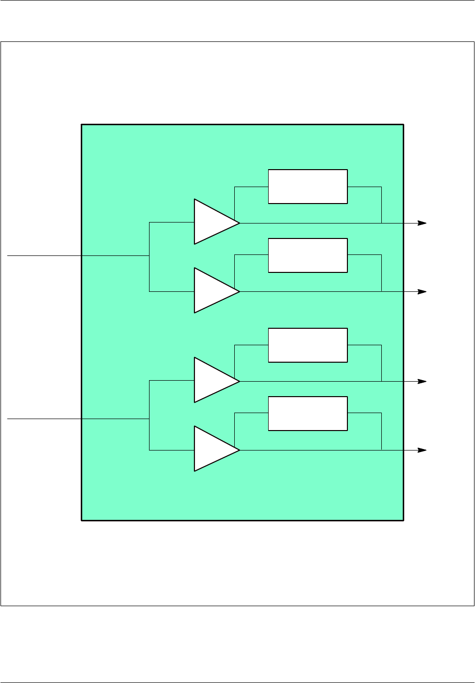
Board descriptionNortel Networks Confidential 2--101
S12000 BTS Reference Manual
Copyright ©2002--2005 Nortel Networks
Power supply
regulation
Power supply
regulation
Power supply
regulation
Power supply
regulation
RX--splitter 2X2
RX0--0
LNA
RF combiner
LNA
LNA
LNA
RX0--1
RX1--0
RX1--1
RF combiner
Figure 2--27 RX--splitter diagram type 2x2
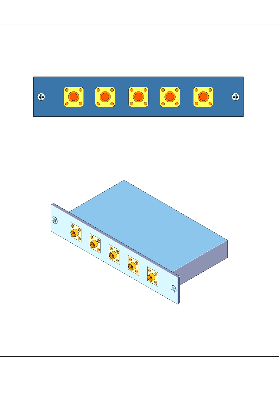
Board description Nortel Networks Confidential
2--102
PE/DCL/DD/0142
411--9001--142 Standard 15.102/EN May 2005 Copyright ©2002--2005 Nortel Networks
RX0 RX1 IN RX2 RX3
Figure 2--28 RX--splitter type 1x4
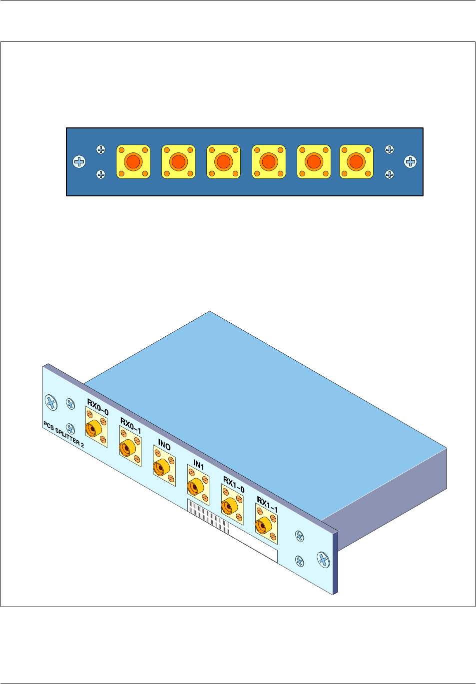
Board descriptionNortel Networks Confidential 2--103
S12000 BTS Reference Manual
Copyright ©2002--2005 Nortel Networks
RX0--0 RX0--1 IN0 RX1--1IN1 RX1--1
Figure 2--29 Rx--splitter type 2x2

Board description Nortel Networks Confidential
2--104
PE/DCL/DD/0142
411--9001--142 Standard 15.102/EN May 2005 Copyright ©2002--2005 Nortel Networks
2.10 Power system
2.10.1 Power system description
This system is made up of:
a Power Controller Unit (PCU) and a set of up to seven Rectifier Units (SRU),
each with 600 W output capability (one is for redundancy)
or a GSM Integrated power System (GIPS)
a set of batteries (Internal or external)
This system and the batteries constitute the dc energy distribution system used to
supply the various modules of the cabinet. The Power System delivers a 54.6 V dc
voltage which it generates from the Mains voltage for a 25°C temperature (77°F)
of the probe under the batteries.
2.10.2 PCU description
The PCU has the four following separate outputs which supply the modules of the
cabinet:
output 1 (--) to the power amplifiers and F--type converters
output 2 (--) to the climatic system fans
output 3 (--) to the DRX units
output 4 (--) to the CBCF, the user optional accessory, and the RECAL board
The PCU also provides a common 0 V output.
PCU protections
The PCU outputs are protected by these breakers:
output current 1: breaker L1 (80 A)
output current 2: breaker L2 (10 A, time delay)
output current 3: breaker L3 (15 A)
output current 4: breaker L4 (15 A)
When circuit--breakers L1 or L3 are tripped, an alarm signal is generated.
A manual power supply cut--off is provided on all four outputs by circuit--breakers
on the front panel of the PCU.
Alarms
Several alarms are provided in the PCU, in order to detect the following situations:
ac fault: when the ac supply is interrupted or is outside the voltage range (single
alarm for all rectifiers)
dc fault: when the dc supply is interrupted or is outside the 40 V to 58 V (±0.5 V)
range (single alarm for all rectifiers) or if a temperature sensor is not properly
linked to the PCU or if a local bias fails.

Board descriptionNortel Networks Confidential 2--105
S12000 BTS Reference Manual
Copyright ©2002--2005 Nortel Networks
excessive temperature: The rectifier is switched off when the maximum
operating temperature is exceeded, and then starts again when the temperature
has dropped back to normal (single alarm for all rectifiers).
batteries on discharge (except for S8006 BTS)
PCU protection device
Load1 threshold
Alarm connector
This is a male 15--point SubD connector:
1ac fault alarm
2dc fault alarm
3NC
4Alarm common
5Load1 threshold alarm
6NC
7Over temperature alarm
8PCU protection alarm
9Battery on discharge
10 NC
11 NC
12 NC
13 NC
14 NC
15 NC
Note: Only alarms sent back to the RECAL
board are mentionned.
Table 2--70 Alarm connector

Board description Nortel Networks Confidential
2--106
PE/DCL/DD/0142
411--9001--142 Standard 15.102/EN May 2005 Copyright ©2002--2005 Nortel Networks
Monitoring connector
This is a female 15--point SubD connector:
1Alarm common
2Alarm common
3NC
4NC
5NC
6NC
7NC
8CEATS 1a
9CEATS 1b
10 NC
11 NC
12 Mechanical ground
13 Mechanical ground
14 NC
15 NC
Note: NC = not connected
Table 2--71 Monitoring connector
2.10.2.1 PCU Front panel
The front panel includes the following (see Figure 2--30):
four manual circuit breakers (PA, FAN, DRX and BCF)
test points:
•
two points for type1 (PROBE1 and PROBE2)
•
one point for type2 (PROBE1 only)
a terminal for connection with the battery cables
six lights emitting LEDs
•
The green LED (ON) indicates that the PCU is operating normally.
•
The red LED (AL) indicates that there is a fault in the temperature sensor
circuit of the batteries or in the PCU.
•
Four other green LEDs indicates that the four outputs of the PCU are
operational.

Board descriptionNortel Networks Confidential 2--107
S12000 BTS Reference Manual
Copyright ©2002--2005 Nortel Networks
2.10.2.2 PCU Top panel
The top panel includes alarm and monitoring connectors. The alarm connector (J4)
is a male type, while the control connector (J5) is a female type.
LEDs
The LEDs give information on the status of the PCU rectifier:
The green LED (ON) indicates that the PCU is operating normally.
The red LED (AL) indicates that there is a fault in the temperature sensor circuit
of the batteries or in the PCU local bias system.
Four other green LEDs indicates that the four outputs of the PCU are operational.
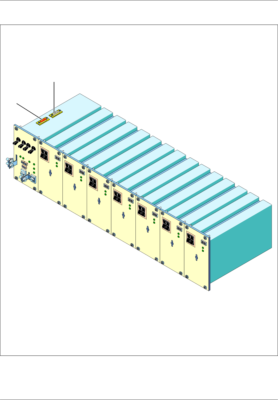
Board description Nortel Networks Confidential
2--108
PE/DCL/DD/0142
411--9001--142 Standard 15.102/EN May 2005 Copyright ©2002--2005 Nortel Networks
J4
J5
Figure 2--30 Power supply rack (seven--rectifier type)

Board descriptionNortel Networks Confidential 2--109
S12000 BTS Reference Manual
Copyright ©2002--2005 Nortel Networks
2.10.3 SRU description
Input voltage
Nominal 230 V ac
Range: 176 V ac to 264 V ac
Output characteristics
Nominal output voltage is 54.6 V ±0.2 V.
The output voltage range is 40 V to 58 V ±0.5 V.
Protection against power surges is 59.5 V (+0 V, --1 V).
Nominal current is 11A minimum for Vout = 54.6 V. The output power is constant
(600W) for output voltages between 40 V and 58 V.
Alarms
Several alarm signals can be generated, in the following cases:
overtemperature
missing module
ac input voltage interrupted or not within 176 V--264 V thresholds
dc output voltage not within 40 V--58 V thresholds (±0.5 V)
An ac alarm leads to a dc alarm, but a dc alarm does not necessarily lead to an ac
alarm.
Floating voltage control
The floating voltage leaving the rectifiers is automatically adjusted in inverse ratio
to battery temperature. This floating voltage is necessary for an optimum battery
service life.
2.10.3.1 SRU Front panel
The front panel includes the following (see Figure 2--30):
a manual circuit switch
two voltage test points
two LEDs

Board description Nortel Networks Confidential
2--110
PE/DCL/DD/0142
411--9001--142 Standard 15.102/EN May 2005 Copyright ©2002--2005 Nortel Networks
The LEDs give information on the status of the rectifier:
The green LED (ON) is on to indicate that the rectifier is in normal operating
mode, that is, the ac supply is within the appropriate voltage range and a dc
voltage is supplied at the rectifier output.
The red LED (AL) is on to indicate that the ac supply is within the appropriate
voltage range but rectifier temperature is too high.
2.10.4 GIPS description
This system is made up of a Distribution and Control Unit (DCU), a Set of Rectifier
Units, rectifiers of 680 W each (one is for redundancy), and a AC Distribution Unit
(ADU). This GIPS and the batteries constitute the dc energy distribution system
used to supply the various modules of the cabinet. The Power System delivers a 54.6
V dc voltage which it generates from the Mains voltage for a 25°C temperature
(77°F) of the probe under the batteries.
2.10.4.1 DCU description
The DCU has the four following separate outputs which supply the modules of the
cabinet:
output PA (--) to the power amplifiers
output DACS (--) to the climatic system fans
output DRX (--) to the DRX, eDRX, or DRX--ND3 units
output BCF (--) to the BCF (CBCF/RECAL /USER) and F--type converters
The DCU also provides a common 0 V output.
DCU protections
The DCU outputs are protected by the following breakers:
output current PA: breaker CB1 (80 A)
output current DACS: breaker CB2 (15 A)
output current DRX: breaker CB3 (15 A)
output current BCF: breaker CB4 (15 A)
When circuit--breakers CB1 or CB3 are tripped, an alarm signal is generated.
A manual power supply cut--off is provided on all four outputs by circuit--breakers
on the front panel of the DCU.
Alarms
Several alarms are provided to the RECAL board by the power system:
AC fault: when 1 out of 3 phases is interrupted or is outside the 172V to 176V
range (single alarm for all seven rectifiers)
DC fault: when the dc supply is interrupted (single alarm for all seven rectifiers)
or if a temperature sensor is not properly linked to the DCU or if a local bias fails
or one slot is empty.

Board descriptionNortel Networks Confidential 2--111
S12000 BTS Reference Manual
Copyright ©2002--2005 Nortel Networks
DCU protection device
Load1 threshold
Main breaker fault
Lightning arrestor fault
Alarm connector
This is a male 15--point SubD connector placed on the top of the DCU.
1Alarm AC OR
2Alarm DC OR
3Alarm load1 threshold
4Common alarms
5Remote Control a
6Remote Control b
7CEATS1
8CEATS2
9NC
10 Mains breaker
11 PCU Protective Devices
12 NC
13 Lightning Arrestor
14 Common Alarm
15 NC
Note: NC = not connected
Table 2--72 Alarm connector

Board description Nortel Networks Confidential
2--112
PE/DCL/DD/0142
411--9001--142 Standard 15.102/EN May 2005 Copyright ©2002--2005 Nortel Networks
2.10.4.2 DCU front panel
The front panel includes the following:
Four manual circuit breakers (PA, DRX, DACS, and BCF)
a battery temperature probe connector
four green LEDs
•
The four green LEDs ON indicate that the DCU is operating normally.
•
A green LED OFF indicates that the corresponding module is not powered.
A battery breaker is located above the GIPS.
2.10.4.3 DCU top panel
The top panel includes an alarm interface connector. The alarm connector is male
15--point SubD connector.
2.10.4.4 Rectifier description
Input voltage
Nominal 230 V ac
Range: 176 V ac to 264 V ac
Output characteristics
Nominal output voltage is 54.6 V ±0.2 %.
The output voltage range is 40 V to 58.3 V.
Protection against power surges is 59.7 V.
Nominal current is 12.45 A minimum for Vout = 54.6 V. The output power is
constant (680W) for output voltages between 40 V and 58 V.
Alarms
Several alarm signals are generated, in the following cases:
overtemperature
ac input voltage interrupted or not within 176 V--264 V thresholds
dc output voltage not within 40 V to 58.3 V thresholds
An ac alarm leads to a dc alarm, but a dc alarm does not necessarily lead to an ac
alarm.
Floating voltage control
The floating voltage leaving the rectifiers is automatically adjusted in inverse ratio
to battery temperature. This floating voltage is necessary for an optimum battery
service life.

Board descriptionNortel Networks Confidential 2--113
S12000 BTS Reference Manual
Copyright ©2002--2005 Nortel Networks
2.10.4.5 Rectifier front panel
The front panel includes the following:
a manual circuit switch
a green LED
The LED gives information on the status of the rectifier. The green LED is on to
indicate that the rectifier is in normal operating mode, that is a dc voltage is supplied
at the rectifier output.
2.10.4.6 ADU description
The ADU provides:
the AC input cable
surge protection
a system level circuit breaker for rectifiers power on/off and overload protection
a circuit breaker for DACS power on/off and overload protection
EMI filtering
a connector for the DACS
2.10.4.7 ADU front panel
The front panel includes the following:
three mains circuit breakers:
•
rectifiers 1, 3, 5, 7 Load Circuit Breaker
•
rectiifers 2, 4, 6 Load Circuit Breaker
•
DACS Load Circuit Breaker
DACS cable
main cable
Earth connection point for dielectric test
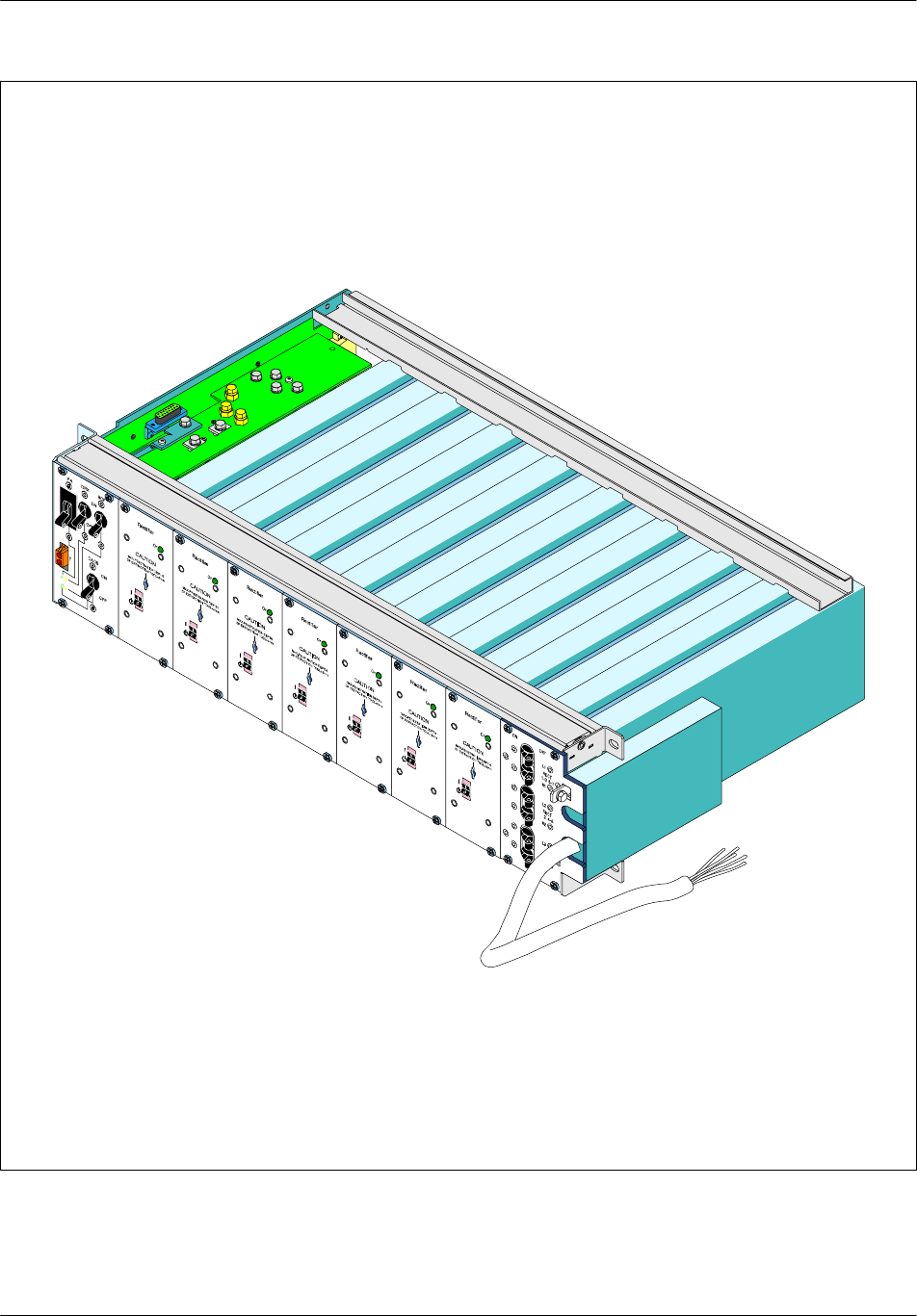
Board description Nortel Networks Confidential
2--114
PE/DCL/DD/0142
411--9001--142 Standard 15.102/EN May 2005 Copyright ©2002--2005 Nortel Networks
Figure 2--31 GIPS
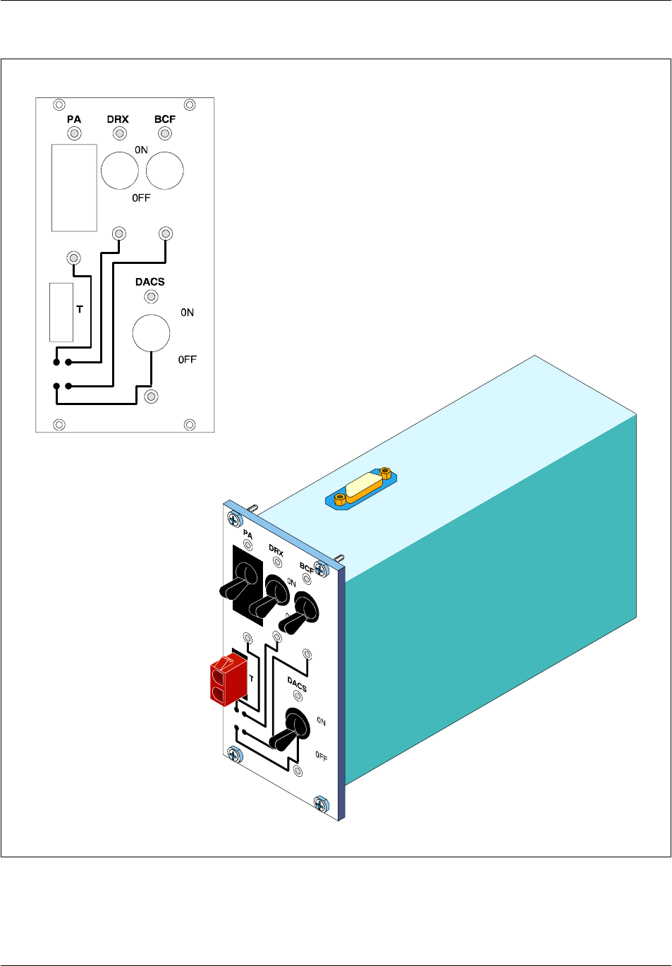
Board descriptionNortel Networks Confidential 2--115
S12000 BTS Reference Manual
Copyright ©2002--2005 Nortel Networks
Figure 2--32 DCU module
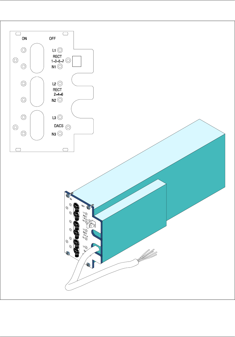
Board description Nortel Networks Confidential
2--116
PE/DCL/DD/0142
411--9001--142 Standard 15.102/EN May 2005 Copyright ©2002--2005 Nortel Networks
Figure 2--33 ADU module

ArchitectureNortel Networks Confidential 3--1
S12000 BTS Reference Manual
Copyright ©2002--2005 Nortel Networks
3 ARCHITECTURE
3.1 Physical architecture
3.1.1 Introduction
This chapter provides an overview of the BTS physical architecture. BTS
components are described in detail in Chapters 1 to 5.
The EDGE link quality measurement (LQM) of the uplink is performed at the BTS.
E--DRX and E--PA are necessary on the BTS to utilize the EDGE features.
BSC12000 is required to utilize the EDGE features.
3.1.2 Subsystems
The BTS contains three main subsystems (see Figure 3--1):
one CBCF Module
one TRX subsystem
one coupling system
The content of each subsystem is listed in Table 3--1.
3.1.3 Internal buses
The following buses, which connect BTS components, are described in this section:
frequency hopping (FH) bus
private PCM
Figure 3--1 shows the buses used with the CBCF Module.

Architecture Nortel Networks Confidential
3--2
PE/DCL/DD/0142
411--9001--142 Standard 15.102/EN May 2005 Copyright ©2002--2005 Nortel Networks
Subsystem Contents*
Compact BCF (CBCF) Module •Compact PCM Interface board (CPCMI)
•Compact Main Common Function board
(CMCF)
•Remote Control Alarm (RECAL) board
•BCF Interconnection board (BCFICO)
•CBCF Back Panel (CBP)
TRX •Driver and Receiver unit (DRX)
•Power Amplifier (PA)
Coupling system •RF Combiner Module(s) of the following
types:
-- Duplexer (D)
-- Hybrid Two--way (H2D)
-- Hybrid Four--way (H4D)
-- Tx Filter(s) (TxF)
•Rx Splitter(s)
•LNA Splitter
* The number of boards or modules are not indicated and depend on the
configuration of the site.
Table 3--1 BTS subsystems
3.1.3.1 FH bus
The FH bus links together all logical DRXs.
The FH bus and the transmitters connected to it ensure the function of frequency
hopping and the filling of the BCCH frequency.
The FH bus is a V11 (series) bus. It is one-way and carries the signals according to
the RS485 standard.
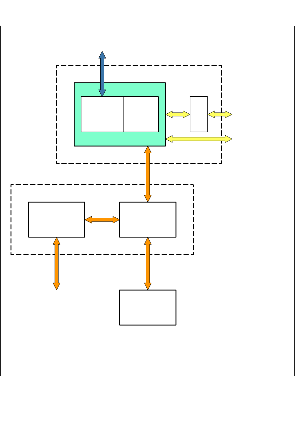
ArchitectureNortel Networks Confidential 3--3
S12000 BTS Reference Manual
Copyright ©2002--2005 Nortel Networks
PA
TRX
DRX
DRX Logic
part
CPCMI CMCF
CBCF (*)
RECAL
Private PCM
DRX Radio
part
Private
PCMs
Note: (*) The two interconnection boards of the CBCF module (BCFICO and CBP) are not shown.
FH bus
Private PCMs
External PCMs
Transmitter coupler
subsystem
Reception coupler
subsystem
Figure 3--1 Subsystem architecture with CBCF

Architecture Nortel Networks Confidential
3--4
PE/DCL/DD/0142
411--9001--142 Standard 15.102/EN May 2005 Copyright ©2002--2005 Nortel Networks
Each message is transmitted in synchronization with the 4Fbit clock and includes
the following:
the system time in six bytes (flag included)
the address of the DRX that transmits the information in one byte
the code of the send frequency on 10 bits
the send power commands in one byte
the NRZ message of the send data in 19 bytes
Up to 16 transmitters can be connected to this bus.
For multi--cell sites, all the cells can be connected onto a single FH bus.
3.1.3.2 Private PCM
Up to six private PCMs transport data between the DRXs and the CBCF Module.
Each private PCM supports up to four es. Each private PCM has a 64 kbit/s time
slot (TS) distributed to all DRXs and carries the GSM TIME signal (TS31).
Each private PCM allocates the following time slots (TS) for each DRX:
One TS (64 kbit/s logical channels) of transparent data for signaling and 4 TSs
for traffic
A group of five TSs, three of which are used, is allocated to each DRX, as follows:
Signaling Traffic +
Joker
Traffic +
Joker
Traffic +
Joker
Traffic +
Joker
1234 5
A 4.096 MHz clock, slaved to the 4Fbit clock of the synchronization board, is used
for bit synchronization of the private PCM.
The refresh period must be a multiple of an occurrence between the GSM time base
(577 µs) and the PCM time base (125 µs). The selected refresh period is 60 ms.
One must make the difference between CMCF/CPCMI which remain with a single
rate (4.096 MHz clock and 2.048 Mbps datarate) and CMCF/DRX/RECAL which
can have a double rate feature on some TSs(4.096 Mbps double datarate).
The TSs remaining with a single rate are the signaling TSs for the
DRX/eDRX/RECAL and the traffic TSs for the DRX.

ArchitectureNortel Networks Confidential 3--5
S12000 BTS Reference Manual
Copyright ©2002--2005 Nortel Networks
3.2 CBCF functional architecture
The CBCF performs the following functions:
switching, synchronization, and concentration
control of the alarm management unit
PCM Interface
The CMCF Phase2 board performs the concentration, synchronization, and
switching functions. The CMCF also controls the alarm management unit (the
RECAL board), which is located outside the CBCF Module.
The CMCF Phase2 board allows operation in duplex mode and in simplex mode.
The CPCMI board is the interface between the external PCM links (A--bis) and the
private PCMs in the CBCF.
CBCF modes
The CBCF can be used in simplex mode with only one CMCF board in slot 0 or 1
running in active mode. Simplex/Duplex mode is managed by a micro switch on the
CMCF Phase2 board. From duplex to simplex, the transaction is never automatic
and always follows a configuration. From simplex to duplex mode, there is no
automatic transition when the active board detects the connection with the passive
one.
3.2.1 Switching, synchronization, and concentration
The CMCF Phase2 board is duplicated in the CBCF Module to provide redundancy
(see Figure 3--2).
One CMCF central processor manages the switching matrix and the
synchronization. The main processor and slave processor share the concentration
and routing tasks as described below.
3.2.1.1 Switching
The two switching matrices in the CMCF receive and distribute the traffic of PCMs
as follows:
up to six PCMs communicate with the CPCMI boards (external PCM)
up to six PCMs communicate with the DRXs (external PCM)
two PCMs communicate with the processing units (internal PCM)
one PCM communicates GSM time (internal PCM)
one PCM for tests (internal PCM)

Architecture Nortel Networks Confidential
3--6
PE/DCL/DD/0142
411--9001--142 Standard 15.102/EN May 2005 Copyright ©2002--2005 Nortel Networks
The 6 PCMs distributed towards the DRX can have a double rate.
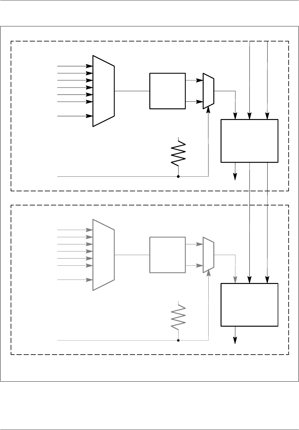
ArchitectureNortel Networks Confidential 3--7
S12000 BTS Reference Manual
Copyright ©2002--2005 Nortel Networks
1/256
1/193
H8M SY H4M
SYN
FLL
E1/T1
+5V
1/256
1/193
H8M SY H4M
E1
+5V
MASTER CMCF
SLAVE CMCF
PLL : Phase--locked loop
FLL : Frequency locked loop
SYN
PLL
SIX
CLOCKS
SIX
CLOCKS
Figure 3--2 CMCF board synchronization (full configuration)

Architecture Nortel Networks Confidential
3--8
PE/DCL/DD/0142
411--9001--142 Standard 15.102/EN May 2005 Copyright ©2002--2005 Nortel Networks
3.2.1.2 Synchronization
The CMCF Phase2 board provides synchronization to the radio part of the BTS.

ArchitectureNortel Networks Confidential 3--9
S12000 BTS Reference Manual
Copyright ©2002--2005 Nortel Networks
Synchronization is obtained through a temperature--controlled oscillator that allows
the selection of timing signal from eight signals (six from the external PCMs, one
from an external source, and one from the CMCF Phase2 active).
The selected clock signal is routed to a digital phase comparator that authorizes
synchronization operations in a frequency locked loop (CMCF Phase2 active) or in
a phase locked loop (CMCF Phase2 passive).
The CMCF Phase2 passive operates in a phase locked loop so that its H4M clock
is synchronized with that of the CMCF Phase2 active. This ensures that phase
hopping does not occur during a CMCF Phase2 switchover.
GSM Time
The processing unit transmits the GSM Time every 60 ms. The GSM Time is
transmitted to the switching matrices of the CMCF Phase2 active. The CMCF
passive reads the GSM Time in the CMCF Phase2 active, which allows the
synchronization of GSM Time on both CMCFs.
Figure 3--2 shows the synchronization process on the CMCF Phase2 board.
Switchover
A switchover occurs in synchronization with the H4M clock. Since the active
CMCF and the passive CMCF Phase2 are synchronized (H4M and GSM Time), the
switchover does not cause a timing disruption.
The switchover sequence is as follows:
active CMCF becomes inactive
inactive CMCF detects the inactivity
inactive CMCF becomes active
A CMCF processor becomes inactive in the following circumstances:
H16M clock state is NOK and there is dual chain operation
the active request is disabled
master board is not properly connected to the back panel
the active processor is reset while in dual chain operation
Defence and redundancy management
A switchover from one CMCF Phase2 board to the other in the event of an error on
the active CMCF Phase2 board ensures redundancy. The hardware supports duplex
and simplex modes.
A redundancy channel between both CMCF Phase2 boards ensures the exchange
of data between the boards in the event of a switchover.
The defense connectivity is shown in Figure 3--3.
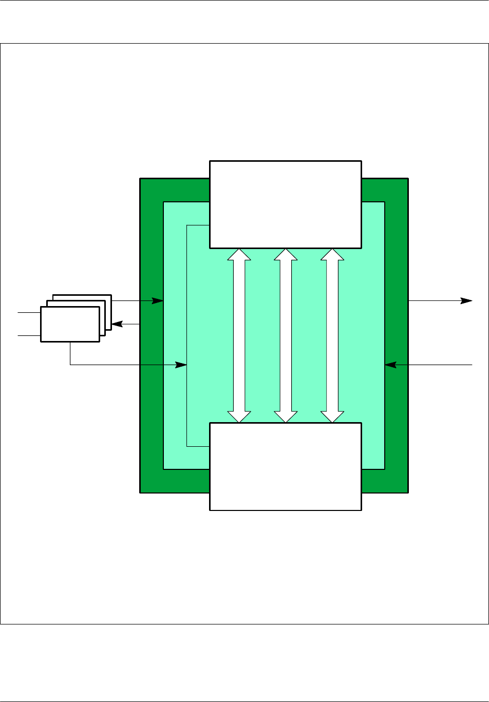
Architecture Nortel Networks Confidential
3--10
PE/DCL/DD/0142
411--9001--142 Standard 15.102/EN May 2005 Copyright ©2002--2005 Nortel Networks
MASTER CMCF
SLAVE CMCF
CPCMI
Six Private
PCMs
Six PCMs
Six Clocks
M/S logic witch
Duplex sync
Redundancy link
Figure 3--3 Defense connectivity between the CMCF Phase2 boards (full
configuration)

ArchitectureNortel Networks Confidential 3--11
S12000 BTS Reference Manual
Copyright ©2002--2005 Nortel Networks
3.2.1.3 Concentration and routing
The concentration and routing functionality is performed by the active and passive
processing units. The master processing unit manages the board resources. The
passive processing unit, which operates synchronously with the master unit,
manages one PCM, one HDLC link (for active--passive communication), and one
RS232 link.
The master processing unit receives an external clock signal at 4.096 MHz and
generates a 33 MHz reference frequency. This frequency is supplied to the passive
unit so that it can be synchronous with the master unit.
3.2.2 Control of the alarm management unit
The CMCF Phase2 manages the alarm management unit, the RECAL board, located
outside the CBCF Module.
The RECAL board collects internal and external alarms and routes them to the
CMCF, which routes to the BSC.
The communication between the CMCF Phase2 and the RECAL is done using an
LAPD protocol link that uses a channel supported by time slot 25 of PCM0.
3.2.3 PCM Interface
Up to three CPCMI boards provide the interface between six external PCM links
(A--bis) and six private PCMs used inside the CBCF Module.
The interface tasks correspond to an electrical level translation and a frame format
conversion depending on the type of external PCM link (PCM E1, PCM T1, or
HDSL).
The external PCM interface has functional blocs that perform the following
functions:
conversion of analog signals on the A--bis interface and the logical signals of the
Framer part of the PCMI
management of the synchronization clock
transposition between the A--bis and the private PCMs signals
3.2.3.1 Signalling interfaces
The CPCMI board uses the PCM and HDSL interfaces described below.
PCM A--bis interface
The E1 interface is compatible with the G703 Recommendation. Its impedance is
120 (two pairs of bidirectional symmetrical links) or 75 Ohms (coaxial cables).
The T1 interface is compatible with ANSI T1.403 and T1.102. Its impedance is
100 Ohms (two pairs of bidirectional symmetrical links).

Architecture Nortel Networks Confidential
3--12
PE/DCL/DD/0142
411--9001--142 Standard 15.102/EN May 2005 Copyright ©2002--2005 Nortel Networks
HDSL A--bis interface
The HDSL--E1 format (2B1Q) is on one single twisted copper pair where the
transmission rate is 2320 kbps for a full E1 frame. This rate is compatible with the
ETSI ETR 152 RTR/TM--06002 standard.
The HDSL--T1 format (2B1Q) is on one single twisted copper pair where the
transmission rate is 1552 kbps for a full T1 frame. This rate is not standardized and
is considered a proprietary link.
Private PCMs
One CPCMI board is connected to two private PCM links (PCM0 and PCM1). The
O&M communication is done through an HDLC link using TS0 of PCM0.
E1/T1
Three bits supplied to the CMCF indicate whether the board is an E1 or T1.

ArchitectureNortel Networks Confidential 3--13
S12000 BTS Reference Manual
Copyright ©2002--2005 Nortel Networks
3.3 DRX functional architecture
The DRX board has a digital part, a radio part and a power supply board
(Figure 3--4).
3.3.1 Types of DRX boards
The DRX boards for S12000 indoor are:
DRX ND3 GSM 900 MHZ
DRX ND module 1800 MHZ
DRX ND PCS 19000 MHZ
E--GSM DRX ND module
The DRX boards for S12000 outdoor are:
DRXNDPCS
DRXNDDCS
DRXNDE--GSM
MOD: DRX ND3 GSM
3.3.2 DRX digital part
The DRX digital part consists of four units:
the Advanced MaNagement Unit (AMNU), which manages the DRX
the Digital Control Unit for eight chanels (DCU8), which is the signal processing
unit
the Time Base Unit (BDT), which manages the GSM_TIME for the DRX
TX logic, which is the interface with the transmission part in the DRX Radio
board
3.3.2.1 AMNU unit
The AMNU unit manages the DRX. It manages the eight time slots of a TDMA
frame and the radio signaling functions.
These functions can be broken down into communication functions (RSL) on the
one hand, and operating and maintenance functions (O&M) on the other (see
Figure 3--5).
Communication functions
Communication functions include:

Architecture Nortel Networks Confidential
3--14
PE/DCL/DD/0142
411--9001--142 Standard 15.102/EN May 2005 Copyright ©2002--2005 Nortel Networks
routing functions
concentration functions
Routing functions
The TDMA frame management unit routes messages from the BSC. The messages
arrive on the RSL and can be broken down into two categories:
messages concerning processing of a single time slot
messages concerning all the time slots in the TDMA frame
Concentration functions
There are two types of messages:
transparent messages
non--transparent messages
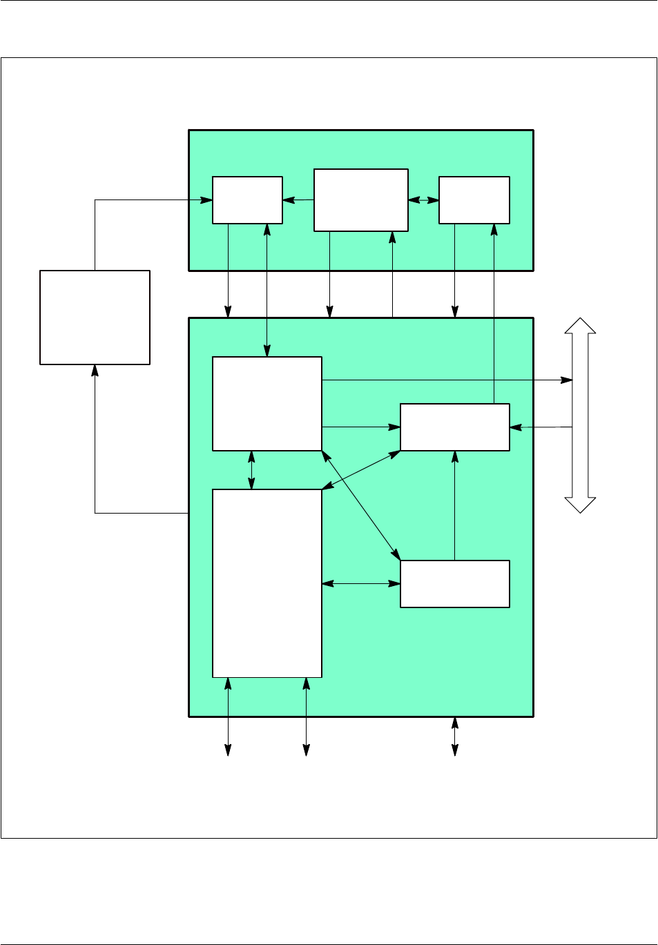
ArchitectureNortel Networks Confidential 3--15
S12000 BTS Reference Manual
Copyright ©2002--2005 Nortel Networks
AMNU
DCU8
RX
Test Ethernet
BDT
DRX digital
FH
bus
Private PCM
Radio DRX
Logical TX
TX
Power
supply
board
+5.4V
+ 12V
-- 12V
+ 48Vdc
Frequency
reference
unit
Figure 3--4 DRX board: functional block diagram
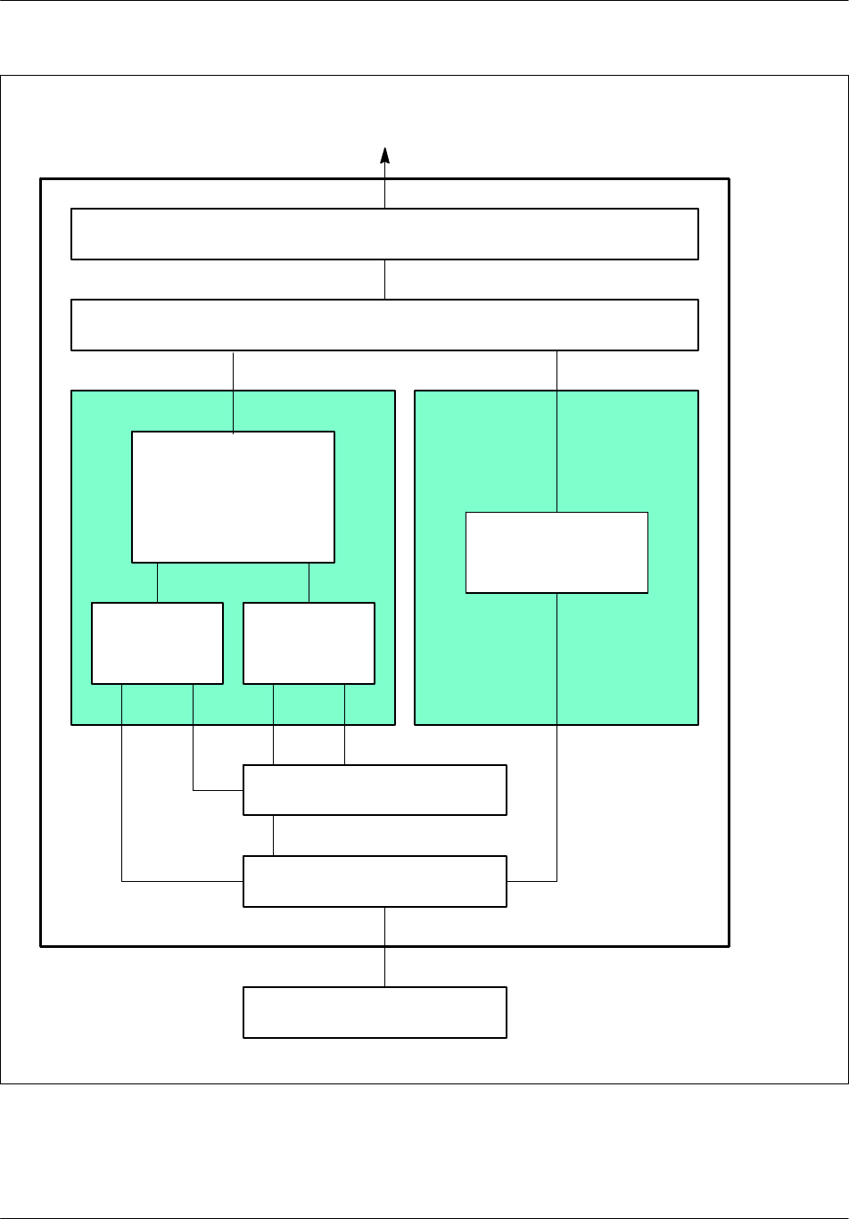
Architecture Nortel Networks Confidential
3--16
PE/DCL/DD/0142
411--9001--142 Standard 15.102/EN May 2005 Copyright ©2002--2005 Nortel Networks
SPU
AMNU
BSC
O&M
Communication
function (RSL):
-- routing
-- concentration
Level 1 radio access
Level 1 radio
Level 2 radio management
Radio
resources
management
Radio
measurements
management
Operations &
Maintenance
functions (O&M)
Level 3 radio
Level 1 wires
Level 2 wires
Figure 3--5 AMNU functions

ArchitectureNortel Networks Confidential 3--17
S12000 BTS Reference Manual
Copyright ©2002--2005 Nortel Networks
Transparent messages are simply concentrated on a time slot of the internal PCM.
Non--transparent messages are:
radio measurement messages of the mobile
interference measurement messages on the inactive channels
load messages on the RACH channel
load messages on the PCH channel
Non--transparent messages are transcoded, averaged and grouped in a single
message to the BSC. This message is sent to the same time slot as the transparent
messages.
Operation & Maintenance functions
The following Operation & Maintenance functions are processed by the Frame
management unit (AMNU):
start--up, downloading, initialization
configuration
monitoring/defense
Start--up/Downloading/Initialization
The AMNU is started by a hardware reset or a reinitialization message sent by the
BSC. It causes configuration of the LAPD and establishment of the OML link with
the BSC.
The DRX subsystem can be downloaded only after the BCF is downloaded, and
the units of site management, cell management, and Abis signaling of the DRXs
have been configured.
The BSC systematically initiates a downloading phase of the catalogue files and of
the following software units:
AMNU
SPU
DLU
BOOT
TX
BDT
BIST of the SPUs
A re--flashing of the units for which the software versions are different follows the
downloading.

Architecture Nortel Networks Confidential
3--18
PE/DCL/DD/0142
411--9001--142 Standard 15.102/EN May 2005 Copyright ©2002--2005 Nortel Networks
Configuration
The DRX is configured by the BSC by means of an OML link on the Abis interface.
Configuration can be broken down into:
a general configuration:
•
configuration of the TDMA frame
time slot configurations:
•
configuration of radio time slots
•
configuration of the frequency hop
Configuration of the TDMA frame provides the DRX with parameters shared by
the whole cell, such as:
cell identity (BSIC)
BCCH frequency
indication of frequency hopping implementation
cell type (normal or extended)
and with parameters specific to the DRX:
the frequency of the TDMA frame if there is no frequency hopping
indication of implentation of diversity in reception
The TDMA frame cannot be dynamically configured. A change of configuration
requires re--start of the downloaded software.
The configuration of the radio time slot specifies the type of logical channel to use
for a time slot.
The configuration of the frequency hopping specifies, for a time slot, the list of
frequencies to use as well as sequencing. This configuration is optional and only
appears if the frequency hopping was requested in the TDMA frame configuration.
Monitoring
The BSC regularly sends status requests to the DRX to detect any problems on the
OML link.
LAPD break
The LAPD, OML and RSL links are monitored by a timer. If level 2 loss is detected,
the BSC and the AMNU try to reconnect. If connection has not been made by the
end of the time--out, the AMNU is reinitialized.

ArchitectureNortel Networks Confidential 3--19
S12000 BTS Reference Manual
Copyright ©2002--2005 Nortel Networks
Event reports
The AMNU collects all events detected by the DRX equipment. It performs
filtration, and sends error reports to the BSC. Transmission error reports and fault
management on RX--splitters alarms are sent through the CBCF.
The AMNU filters to prevent repetition of non--transient events, which means it can
send the BSC a single indication.
The AMNU sends errors to the BSC by sending “event report” messages. There are
two types of “event report” messages:
transient messages, which are not acknowledged by the BSC
non--transient messages, which must be acknowledged by the BSC, and which
are repeated by AMNU until they are acknowledged
Radio signaling function
The radio signaling function supports two Signal Processing Units (SPU). Each
SPU manages one time slot.
Two versions of the SPU software are available. One corresponds to propagation
conditions in rural areas and the other to propagation conditions in urban areas. For
rural areas, the algorithm parameter is set at zero. For urban areas, the alogrith
parameter is set at 0.5, and the interferer cancellation algorithm is active.
The radio signaling functions can be broken down into four groups of functions:
level 1 radio access
level 2 radio management of LAPDm signaling
level 3 radio management, which is made up of two functions:
•
radio resources management
•
radio measurements management
operation & maintenance
Level 1 radio access
Level 1 radio access makes it possible to manage dialogue between the AMNU
signaling function and the SPU processors that are connected to the AMNU. It
offers:
configuration of operating modes for each SPU
SPU control
transmission and reception of data on the radio channel, respecting methods for
slaving to the radio frequency
Level 2 radio management
Level 2 radio management manages the LAPDm level 2 signaling on the radio
channels.

Architecture Nortel Networks Confidential
3--20
PE/DCL/DD/0142
411--9001--142 Standard 15.102/EN May 2005 Copyright ©2002--2005 Nortel Networks
Radio resources management ( level 3 radio)
Radio level 3 provides the following functions:
level 2 management on the common channels
control of level 2 functions on dedicated channels
activation of the common channels
organization of the Common Control CHannel (CCCH), including chaining and
repetition of paging messages and transmission of dedicated channel allocation
messages
activation or deactivation of dedicated channels, implementation of encryption
and channel mode changes
providing SPU processors with system information on the SAACH and BCCH
channels
detection of “random access” and “handover access”
detection of paging channel (PCH) load
detection of radio link attenuation (monitoring of the upstream SACCH
channel), verifiable by the OMC
sending of the mobile transmission power change
Radio measurements management (level 3 radio)
This provides the following functions:
return of interference measurements carried out by the SPU processors on the
inactive dedicated channels and transmission of these measurements to the
AMNU
concatenation of measurements made by the SPUs on the active dedicated
channels and those transferred by the mobile over the same period
Operation & maintenance functions (O&M)
These functions provide configuration and deconfiguration of the time slots and
frequency hopping functions.
Network ID
With the implementation of V15.0, the BTS detects the type of DRX and PA during
connection with respect to the BCF and the DRX. Note the following restrictions:
If a DRX is not yet connected to the BCF, its type is set to “DRX type” until it is
connected.
If a PA is not yet connected to the DRX, its type is set to “PA type” until it is
connected.

ArchitectureNortel Networks Confidential 3--21
S12000 BTS Reference Manual
Copyright ©2002--2005 Nortel Networks
If a fault beginning has been sent on the DRX type (or PA type) of equipment,
because the real equipment type was unknown, the fault ending must be sent on a
DRX or PA type, even if the DRX or PA have connected themselves between the
fault begin and fault end.
EDGE implementation
In V15.1, the BSC can configure one TDMA with up to:
8 DS0 (joker and main) per TRX (with CBCF, CMCF Phase 2)
The joker channel is used when the size of the frame exceeds the size of the main
channel, which is the case for CS3/CS4 in GPRS and MCS3 to MCS9 in E--GPRS.
In that case, the main channel is filled with the maximum information (i.e 302 bits
of payload) and the remainder is split into N equal pieces that are sent in the Joker
channel during the same 20ms period. In order to save PCU CPU Power, the content
of the jokers is aligned on a byte boundary.
As the maximum number of joker TS per TDMA is directly linked to the type of
site, the following rule is mandatory: both chains of the site must have the same level
of hardware.
If this rule is not verified: see the engineering rules for more details.
3.3.2.2 DCU8 unit
The DCU8 unit consists of two signaling processing chains, A and B, as shown in
Figure 3--6. Each chain handles four calls in full--rate voice mode and eight calls
in half--rate voice mode. Chain A and chain B are connected to a subassembly, the
BB_FILT ASIC, which is the interface with the radio part and filters reception
samples before sending them to the two chains. A second subassembly, the CHIF,
which is associated with the BB_FILT ASIC, calculates encryption and decryption
masks.
Chain A processes even radio reception time slots and odd radio transmission time
slots. Conversely, chain B processes odd radio reception time slots and even radio
transmission time slots.
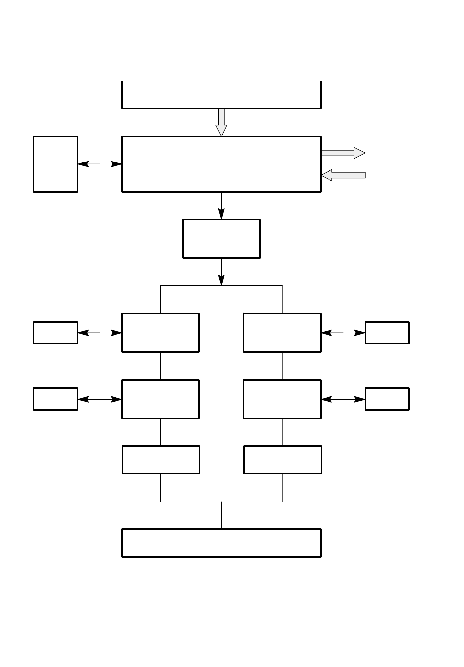
Architecture Nortel Networks Confidential
3--22
PE/DCL/DD/0142
411--9001--142 Standard 15.102/EN May 2005 Copyright ©2002--2005 Nortel Networks
BB_FILTCHIF
RAM
AMNU
DSP DECOD DSP DECOD RAM
DSP TRANS DSP TRANS
RAM RAM
Receivers
FH bus
GSM TIME bus
SPU (A Chain) SPU (B Chain)
DSP EGAL
DPRAM DPRAM
Figure 3--6 DCU8 unit diagram

ArchitectureNortel Networks Confidential 3--23
S12000 BTS Reference Manual
Copyright ©2002--2005 Nortel Networks
The DCU8 unit has five DSPs:
one EGAL DSP, which equalizes the reception signal
two DECOD DSPs, which handle reception signal decoding and level 1
sequencing
two TRANS DSPs, which handle transmission signal processing, encoding, and
the interface with the remote transcoder
There is one DECOD DSP and one TRANS DSP in each chain.
SPU
The SPU carries out processing associated with the transmission layer (see
Figure 3--7 and Figure 3--8). Its functions are:
demodulation of GMSK signal at reception
ciphering/deciphering of sent and received data
encoding/decoding and interleaving/de--interleaving of data from the various
channels
encoding/decoding of voice and data (from 13 kbit/s to 16 kbit/s and vice--versa)
transfer of discontinuous transmission (DTX) signal
control of transmitters (GSMK--8PSK) and receivers
processing of radio measurements
Demodulation function
Demodulation consists of extracting the binary data transmitted from the GMSK
signal received, which is 144 bits for a normal burst and 36 bits for an access burst.
This is done for the eight time slots of the radio channel.
The demodulation principle selected takes into account the inter--symbol
interference resulting from smoothing of the transmission phase transitions
(limitation of the transmitted spectrum), multiple path phenomena, and distortion
introduced by the channel filter upon reception.
Implementation of this type of demodulator requires modification of the
transmission channel as concerns pulse response, frequency deviation, and
reception times. Determining these parameters is part of the job of the demodulation
function.
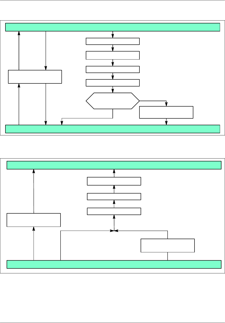
Architecture Nortel Networks Confidential
3--24
PE/DCL/DD/0142
411--9001--142 Standard 15.102/EN May 2005 Copyright ©2002--2005 Nortel Networks
AMNU
SPU
Demodulation
Deciphering (optional)
De--interleaving
Decoding
Speech/data
or signaling
Speech/data
08.60 format coding
Signaling
Receiver
management
DRX radio
Figure 3--7 SPU reception functions
SPU
AMNU
08.60 format
decoding
Transmitter
management
Coding
Interleaving
Ciphering (optional)
Signaling Speech/data
DRX radio
Figure 3--8 SPU transmission functions

ArchitectureNortel Networks Confidential 3--25
S12000 BTS Reference Manual
Copyright ©2002--2005 Nortel Networks
The receiver executes the space diversity function. Both received channels are
combined in an equalizer which carries out joint equalization.
For each of these channels, the pulse response as well as the C/I+N ratio are
estimated. These ratios are used to weight the predictions and samples of each
channel.
The symbols from the equalizer are then decrypted, de--interleaved and decoded to
restore the control messages and traffic sent by the mobile.
Ciphering/deciphering function
The fluxes of binary symbols sent and received on each time slot on the TCH or
SDCCH are encrypted one bit at a time, in compliance with the
ciphering/deciphering algorithm.
The ciphering or deciphering operation protects confidentiality of voice and
signaling. It consists of adding binary bits, one by one, between sent and received
data and a binary train (the ciphering sequence), generated from a ciphering key and
the TDMA frame number of the time slot.
Encoding/decoding and interleaving/de--interleaving functions
All traffic and control logic channels are encoded to protect useful information
against transmission errors. Each channel has its own encoding scheme, usually
including the following steps for each block:
protection of data bits with parity bits or a block code
encoding of the “data bits + check bits” unit with a convolutional code. This
operation results in encoded bits.
rearrangement and interleaving of the encoded bits
burst formating
For data, the encoding procedure depends on the rate: the interleaving level is
higher for data than for voice.
Some channels do not use the encoding schemes described above, in particular the
RACH, FCCH and SCH channels. For these channels, interleaving on several time
slots does not exist.
Mobile transmission timing advance function
The BTS must measure the delay on the received signal when the mobile station
makes itself known.
This measurement, known as timing advance, is forwarded in the dedicated channel
assignment message (immediate assignment) to the MS, which uses this parameter
to anticipate its transmission timing.

Architecture Nortel Networks Confidential
3--26
PE/DCL/DD/0142
411--9001--142 Standard 15.102/EN May 2005 Copyright ©2002--2005 Nortel Networks
During call establishment, the BTS computes the timing advance value and sends
it within CHANNEL REQUIRED message to the BSC. If this value is above the
threshold, then the BSC rejects call establishment.
In ongoing call conditions, the timing advance is calculated at regular intervals and
sent to the MS over the downlink SACCH channel.
The calculation is based on
other measurements taken during demodulation
the timing advance used by the mobile station that is returned in the layer 1
header of the uplink SACCH
Discontinuous transmission (DTX)
Discontinuous transmission allows signals to be sent over the radio channel alone
when a speech signal is present. This limits interference and MS power
consumption. For each call, the MSC indicates whether the BSS “does not use” or
“may use” the DTX.
The principle behind discontinuous transmission is as follows:
The base or mobile vocoder has a Voice Activity Detector (VAD) that detects if the
frame constructed every 20 milliseconds contains speech. If the frame does not
contain speech, the vocoder constructs a special frame called the SIlence Descriptor
(SID) that contains all the background noise description elements. This frame is sent
to produce a comfort noise at the far end, and radio transmission stops.
The vocoder periodically reassesses the ambient noise and reconstructs the SID
frame. The frame produced in this way is sent in step with the SACCH (once every
four 26-frame multiframes, or 480 milliseconds).
When the vocoder detects new speech activity, a special SID frame indicating the
End Of Silence (EOS) is sent, and normal speech frame sending resumes.
On the receive end, additional processing sequences interpret the incoming traffic
frame types (speech, SID, FACCH, nothing) using the related flags (BFI, SID, TAF)
and perform the appropriate operations.
The DTX is allowed for data in non-transparent mode.
BCCH filling
The BCCH frequency must be transmitted continuously so mobile stations can
perform field strength measurements in neighbouring cells.
Continuous transmission is accomplished in various ways:
When frequency hopping is not used, the TRX uses the BCCH frequency as the
carrier frequency for all the channels it supports. The TRX sends fillers on the
BCCH frequency although it may have nothing to send in a given time slot.

ArchitectureNortel Networks Confidential 3--27
S12000 BTS Reference Manual
Copyright ©2002--2005 Nortel Networks
When frequency hopping is being used, one of the following occurs:
•
The hopping laws authorize permanent BCCH transmission, and all the TRXs
help fill operations.
•
The hopping laws do not authorize permanent transmission and a transmitter
is required to enable BCCH “filling” independently and take over when the
hopping laws step down.
Transmitter and receiver control
The SPU controls a transmitter and a receiver. It calculates the frequency hopping
law and determines the frequencies to synthesize.
The transmitter is controlled by the FH bus. The SPU sends the following to the
transmitter:
the power and frequency to use
the bits to send
the time synchronization signal
The SPU sends the following to the receiver:
the frequency to use for the following time slot
the synchronization clock signal
the GSM TIME synchronization signal
The SPU receives the following from the receiver:
digitized samples from the reception channel
the scale factor (gain)
the receiver alarms
Radio measurement processing
The Radio Measurement Processing performed by the BTS ensures that the network
and the mobiles can communicate with each other with minimum interference at the
lowest possible transmission power and with the best transmission quality.
Measurements processed by the BTS include signal strength and signal quality. The
mobile takes measurements in the downlink direction (BTS --> MS), while the BTS
takes them in the uplink direction (MS →BTS). Other measurements include signal
strength on the BCCH frequency of the surrounding cells and the MS_BS distance.
The BTS averages these measurements for each connection. The averaged
measurements are then used as the basis for a decision--making process for the
following:
power control
call clearing
inter--cell handover
intra--cell handover

Architecture Nortel Networks Confidential
3--28
PE/DCL/DD/0142
411--9001--142 Standard 15.102/EN May 2005 Copyright ©2002--2005 Nortel Networks
The BTS cyclically sends to the BSC the interferences measures done on the
inactive channels.
BB_FILT ASIC
The BB_FILT ASIC constitutes the interface between the signal processing unit
(SPU) of the DRX and the radio RX module on the one hand, and the enciphering
ASIC on the other hand. It carries out the band--pass filtering of the digital samples
output by the radio RX module, and generates the FH bus.
A single BB_FILT ASIC processes all eight TSs of the radio frame.
The functions provided by this ASIC include:
GSM time reception interface providing the synchronization of the DSPs on the
radio frame
on transmission:
•
recording of the TX parameters and of the ciphering key, supplied by the DSP
EGAL
•
transfer of the ciphering key to the CHIF ASIC
•
reading of the ciphering template from CHIF ASIC
•
ciphering of the parameters and transmission on the FH bus
on reception:
•
recording of the RX parameters and of the ciphering key, supplied by the DSP
EGAL
•
programming of RX hopping synthesizers
•
generation of channel and sampling frequency selection signals for the analog
to digital converter
•
base--band filtering of the digital samples delivered by the dc converter
•
selection of the best gain for each channel (normal and diversity)
•
transfer of these selected filtered samples to the DSP EGAL
•
transfer of the deciphering key to the CHIF ASIC
•
reading of the deciphering template from CHIF ASIC, and transfer of the
template to the DSP EGAL
3.3.2.3 BDT unit
The BDT (time base) unit regenerates GSM TIME signals. The GSM time is
distributed to the BDT unit of each DRX by means of the GSM TIME channel of
the private PCM every 60 ms.
The value of the propagation delay is sent to the DRX by means of the OML link
of the private PCM. From these two data, each DRX makes the necessary
corrections and regenerates the GSM TIME bus.

ArchitectureNortel Networks Confidential 3--29
S12000 BTS Reference Manual
Copyright ©2002--2005 Nortel Networks
If, for any reason, the GSM time is not distributed on the BDT unit, the BDT unit
locally maintains the GSM TIME bus signals and continues to provide the GSM
time to the DRX units.
The BDT unit is made up of a logic block and a calculation block.
Digital block
The BDT unit receives a 26 MHz clock signal derived from the radio unit clock. This
clock signal has the same stability properties as the 4Fbit clock signal provided by
the BCF synchronization board and is more stable in the short term. The digital
block generates the following signals:
H4M (4.096 MHz)
STRTM (recurrent pulse at 577 microseconds)
TIME_DATA (containing T1, T2, T3 and TN)
Calculation block
The calculation block synchronizes the H4M and STRTM signals with the
synchronization unit signals of the BCF. In addition, it updates the values T1, T2,
T3 and TN.
The synchronization principle consists of forcing a divider--by--24 counter to divide
by 23 (if the BDT is slow) or by 25 (if it is fast). This way, every 23 or 25 periods
of 26 MHz (depending on whether the slow BDT is accelerated or the fast BDT is
slowed down), the BDT corrects a period of 26 MHz.
3.3.2.4 TX logic unit
The main role of the TX logic unit is to control the radio subassembly in real time.
It receives the BCF configuration commands from the AMNU. It carries out the
processing and sends back reports.
Once configured, the TX logic unit reads, on each time slot, the data present on the
FH bus. Then it calculates the frequency code and the power code to be used with
the radio interface.
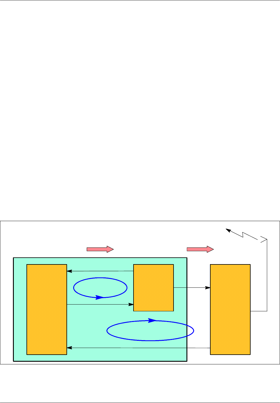
Architecture Nortel Networks Confidential
3--30
PE/DCL/DD/0142
411--9001--142 Standard 15.102/EN May 2005 Copyright ©2002--2005 Nortel Networks
Transmission power
In general, radio power is determined by two inputs. One controls the maximum
static power and the other gives the dynamic attenuation at each time slot.
The static power is given by the CBCF in the CONFIG message. The TX calculates
attenuation to compensate for cable loss between the TX--driver and the power
amplifier.
The dynamic power is provided by the ASIC of the TX logical unit. Its software
reads the value and commands the TX--driver accordingly.
In the case of a BCCH filler, the additional attenuation introduced is always zero.
The power values that the TX and the mobile have to use are fixed by the BTS
according to a control algorithm using the measurements results that it makes and
the thresholds stockpiled in the OMC. The mobile and the BTS power control can
be inhibited by the OMC.
The power control aim is to minimize the interferences, ensure good transmission
quality, and save the mobile’s batteries.
Power slaving
The setpoint value is slaved to compensate for gain variations of the transmission
chain.
Two slaving loops are used to compensate for attenuation in the gain chain.
DRX
TX LOGIC
External loop
GMSK Modulation
Internal loop
Radio Frequency
Antenna
TX DRIVER
Control bus
PA or LPA
Figure 3--9 Power slaving diagram

ArchitectureNortel Networks Confidential 3--31
S12000 BTS Reference Manual
Copyright ©2002--2005 Nortel Networks
These loops can be in the following states:
Open: This state is used for calibration of the internal loop with the external loop.
Initialization: This state is used for loop start--up.
Error: A loop is in error when it is not longer in correspondence with the setpoint.
Closed: A loop is closed when it is in slow slaved mode.
3.3.3 DRX radio part
The DRX radio part is composed of a power supply board and of the DRX radio
board.
The power supply converts common -48 V to specific +5 V/±12 V power supply
signals for the DRX radio board.
The DRX radio board is composed of three units:
the Frequency reference (Fref) unit
the receiver unit (RX)
the transmitter unit (TX)
The DRX boards for S12000 indoor are:
DRX ND3 GSM 900 MHZ
DRX ND module 1800 MHZ
DRX ND PCS 19000 MHZ
E--GSM DRX ND module
The DRX boards for S12000 outdoor are:
DRXNDPCS
DRXNDDCS
DRXNDE--GSM
MOD: DRX ND3 GSM
3.3.3.1 Frequency reference unit
The reference frequency for all local oscillators is derived from the Fref frequency
supplied by the VCXO, itself derived from the 4.096 MHz signal provided by the
DRX digital part (CBCF).
It provides a very steady and spurious--free reference clock for the RX/TX hopping
and fixed synthetizers (13 MHz signal).
3.3.3.2 Receiver unit (RX)
The receiver unit (RX) has four main functions. Slot--to--slot frequency hopping is
achieved with a dual synthetizer arrangement, that is, one is active while the other
is setting to the following frequency. The RX main functions are:

Architecture Nortel Networks Confidential
3--32
PE/DCL/DD/0142
411--9001--142 Standard 15.102/EN May 2005 Copyright ©2002--2005 Nortel Networks
signal down conversion from radio frequency band to Intermediate Frequency
(IF) then to base band frequency
channel filtering (in IF)
RX--level dynamic management
digitization of the base band signal
The base band signal is then sent in binary form with its scale factor to the DRX
digital part. The receiver unit works on signal GMSK and on signal 8--PSK.
Receiver configuration
The receiver configuration is done by the DRX digital part, which sends:
the reception frequency to be used for the following time slot
the synchronization clock signal
the GSM time synchronization signal
Receiver monitoring
The receiver monitors internal equipment: microprocessor and Phase Lock Loops
(PLL).
If there is a failure or other problem, it generates alarms to signal:
microprocessor fault
frequency range not respected (if the frequency to synthesize as requested by the
DRX digital part is incorrect)
PLL loss of alignment (if one of the receiver PLLs is not aligned)
3.3.3.3 Transmitter unit (TX)
The Transmitter unit has two main parts:
IF and RF chains
gain control loop (or Automatic Level Control)
IFandRFChain
An I/Q modulator with a Local Oscillator (LO) phase--locked on a reference
frequency transposes the two baseband I/Q signals into the IF chain.
This 125 MHz local oscillator (LO_IF) phase--locked on a 13 MHz signal translates
the baseband signals into an intermediate frequency. (The IF is 125 MHz in
GSM 850 and 299 MHz in GSM 1900).
The second LO is used for up conversion from IF to RF.

ArchitectureNortel Networks Confidential 3--33
S12000 BTS Reference Manual
Copyright ©2002--2005 Nortel Networks
The up--conversion is followed by bandwidth filter, amplifier stages, variable
voltage attenuators, and digital attenuators.
The transmitter unit works on signal GMSK and on signal 8--PSK.
Gain Control Loop (or Automatic Level Control)
The driver transmit chain upholds the accuracy of the transmission power
compatible with the GSM recommendations against time.
The control dynamics use two components: one voltage variation attenuator (VVA)
and a step--by--step digital attenuator that takes target attenuation into account and
compensates for it.
The Automatic Level Control also includes the PA.

Architecture Nortel Networks Confidential
3--34
PE/DCL/DD/0142
411--9001--142 Standard 15.102/EN May 2005 Copyright ©2002--2005 Nortel Networks
3.3.4 DRX shutting down
3.3.4.1 DRX soft blocking
The DRX soft blocking consists in setting a DRX “out of service” without stopping
the calls established on this DRX. If possible, an intra--cell handover is performed
for those calls to release the DRX more quickly. Otherwise, the DRX will be
released after the normal completion of the calls.
3.3.4.2 DRX soft blocking coupled with a forced handover
To speed up the DRX shutting down, the DRX soft blocking can be coupled with
a forced handover. The calls will be handed over a neighbour cell if the signal
strength is over the handover threshold for that cell.
3.3.4.3 Hint
DRX soft blocking and DRX soft blocking coupled with a forced handover can be
combined into one command. This allows greater efficiency in DRX shut--down.
3.3.5 Power supply board
The power supply card provides a dc voltage between 40.5 V and 57 V, to be
converted into +5 V, +12 V and --12 V. The 48 V voltage is sent first to the logical
DRX unit converter, then, after filtering, to the logical DRX unit and the radio DRX
unit converter.
The power supply of the board varies according to the DRX types and on the
frequencies.
The mechanical and electrical grounds are linked to the common reference zero
volts.

ArchitectureNortel Networks Confidential 3--35
S12000 BTS Reference Manual
Copyright ©2002--2005 Nortel Networks
3.4 e--DRX functional architecture
The e--DRX board consists of (see Figure 3--10):
an e--LDRX digital board including a dc/dc converter, a frame processor TX
logic (GMSK and 8--PSK modulation), and a local time base, working for all
frequency bands
an e--RDRX radio board including a dc/dc converter, a low power driver and a
dual receiver
3.4.1 Modifications between the DRX and e--DRX
This paragraph describes the modifications between the current DRX and the
e--DRX. The main features of the e--DRX are:
signal processing capacity improvement
8--PSK modulation compatibility
receive dynamic extension
TX output power dynamic reduction
packet backhaul readiness
double current on internal PCM
3.4.1.1 e--LDRX board modifications
The main modifications concerning the e--LDRX board are:
the migration of BDT, AMNU, and TX into a single FPGA
the use of one PowerQuicc
the introduction of the 52 MHz frequency reference function
the use of two DSP
the extension of the memory capacity (8 Mb for SDRAM, 4 Mb for flash and
2MbforSRAM)
the size reduction and integration of the dc/dc converter on the e--LDRX board
the lower power consumption (<15W)
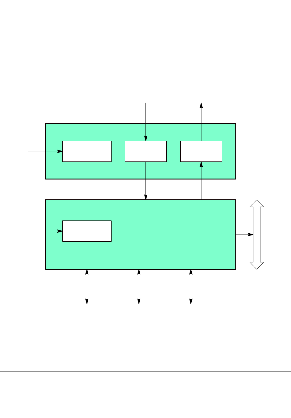
Architecture Nortel Networks Confidential
3--36
PE/DCL/DD/0142
411--9001--142 Standard 15.102/EN May 2005 Copyright ©2002--2005 Nortel Networks
RX
Ethernet
e--LDRX digital board
FH
bus
Private PCM
e--RDRX radio board
TX
DC/DC
converter
DC/DC
converter
Debug
Radio
reception
Radio
transmission
Power
supply
Figure 3--10 e--DRX board: functional block diagram

ArchitectureNortel Networks Confidential 3--37
S12000 BTS Reference Manual
Copyright ©2002--2005 Nortel Networks
3.4.1.2 e--RDRX board modifications
The main modifications concerning the e--RDRX board are:
the removal of the 104 MHz frequency reference
the use of RXIC2 module (IF => BF transposition)
the RX dynamic extension provided by an AGC (--13 to --110 dBm)
the TX output power dynamic reduction
the integration of the dc/dc converter on the e--RDRX board
the lower power consumption (<15W)
double rate on internal PCM
3.4.1.3 e--DRX mechanical/electrical modifications
The main mechanical and electrical modifications applied on the e--DRX are:
RF shielding provided by a single cover
new cooling method: direct forced convection for Digital board
CMS connectors between e--LDRX and e--RDRX
new RF connectors (long thread)
Radio and Digital DC/DC converters are mounted respectively on e--RDRX and
e--LDRX.
CMS DC/DC converters
+5V output e--RDRX DC/DC converter coupled with --5V and +12V discrete
DC/DC converter.
dual tunable output +3.3V/+2.5V or +1.8V e--LDRX DC/DC converter coupled
with +5V discrete DC/DC converter
3.4.2 Main external connections
3.4.2.1 Private PCM
A private internal PCM is used to link the e--DRX to the BCF. The proprietary
interface has the same definition as the previous internal PCM, except that the clock
is fully synchronous with the radio interface.
This bus carries the following information:
Radio Signaling Link (RSL) and local Operation and Maintenance (OML) on
one time slot
Traffic links on two, three, four, six or eight time slots
GSM_TIME channel on a separate time slot
The feature allows the e--DRX to be remotely controlled.

Architecture Nortel Networks Confidential
3--38
PE/DCL/DD/0142
411--9001--142 Standard 15.102/EN May 2005 Copyright ©2002--2005 Nortel Networks
TheTSsforOML/RSLandGSMTimehaveasingleratewhereastheTSsfortraffic
may have a double rate when requested by the CMCF Phase2 board.
Furthermore, the eDRX matrix may also have a double rate when requested by the
CMCF Phase2 board.
3.4.2.2 FH bus
The FH bus defined for the S4000 BTS is used, allowing frequency hopping and
S4000 BTS compatibility. HDLC bus is no longer supported on the e--DRX.
3.4.2.3 e--PA and HePA Control
an asynchronous bi--directional serial link operating in duplex mode carrying at
each RF time slot the mean RF output power of the associated e--PA or the HePA,
its temperature, and e--PA and HePA internal alarms (temperature, current,
VSWR)
a discreet burst synchronization signal. The e--DRX e--PA and e--DRX HePA
Control interface is compatible with both the standard PA, HePA, and the
standard e--PA.
3.4.2.4 Power Supply
The e--DRX is powered by a --48V dc supply. Typical consumption is 25W.
3.4.2.5 Test links
The e--DRX has an Ethernet 10/100 baseT port and an asynchronous serial port. It
also has serial lines for emulator connections, and real time trace facilities.
3.4.2.6 RF interfaces
The e--DRX unit provides RF reception with diversity and RF transmission at low
level.
Low level GMSK RF Output (--3dBm typical / 50 Ohms)
RF Input Main and RF Input diversity (--84 dBm to 0 dBm / 50 Ohms RF inputs
multiplexed with provisional +12V dc. Supply for RF devices (splitters).
3.4.3 e--DRX functional description
This paragraph describes the functional architecture of the e--DRX, but does not
detail each part. The aim is to give enough information to easily approach the main
features.

ArchitectureNortel Networks Confidential 3--39
S12000 BTS Reference Manual
Copyright ©2002--2005 Nortel Networks
3.4.3.1 Logic unit (e--LDRX)
The logic unit (e--LDRX) contains (see Figure 3--11):
an FPGA unit which provides:
•
a control and switching matrix management function
•
a time base function
•
a synchronization function
a management unit (AMNU) which processes:
•
start--up, downloading, initialization
•
configuration
•
monitoring
•
LAPD break
•
event reports
a transmission unit which provides:
•
a radio signaling function
•
a signal processing function
•
a power regulation function
•
a RX logic function
•
a TX logic function
FPGA unit
Control and switching management function
Setting up by setup of e--DRX for AMNU, transmission, and other functions
When the BTS is activated, it must be connected to the BSC to work. A link is set
up on an external PCM link.
Downloading
When communications have been set up with the BSC, the BTS reports its status.
The BSC downloads, if necessary, the software to the BTS.
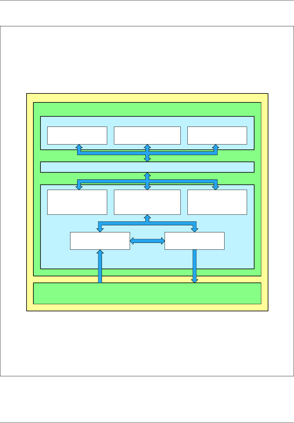
Architecture Nortel Networks Confidential
3--40
PE/DCL/DD/0142
411--9001--142 Standard 15.102/EN May 2005 Copyright ©2002--2005 Nortel Networks
RX logic function TX logic function
Transmission
unit
FPGA unit
Logic unit (e--LDRX)
Processing signal
function
(SPU)
Radio signaling
function
Power regulation
function
Management unit (AMNU)
Synchronization
function
Control and switching
management function Time base
Radio unit (e--RDRX)
Figure 3--11 Logic unit (e--LDRX): functional architecture

ArchitectureNortel Networks Confidential 3--41
S12000 BTS Reference Manual
Copyright ©2002--2005 Nortel Networks
Synchronization management
At the start--up, the BTS selects the clock. During LAPD connection, the BTS
forces the clock onto the PCM carrying the LAPD.
The e--DRX board recognizes the S12000 thanks to the SEL and adapts to the
private PCM mapping.
Switching matrix management
Each PCM link managed by the switching matrix has a transmission test
interface, reception test interface, and an idle interface.
The switching matrix is configured when the BSC requests set up or release of a
signaling or traffic channel from the BTS.
Signaling channels are set up (or broken) between a transmission signaling TS
and a non--concentrated link. This operation may entail (dis)connection between
a concentrated link TS coming from the BTS and a PCM link TS on the PCM
interface.
Traffic channels are set up (or broken) between a transmission traffic TS and a
PCM link TS on the PCM interface.
Data signaling concentration function
The BTS uses this function to set up the communication between the BSC and the
other entities that make up the BTS. This function is implemented with the
LAPD protocol that serves concentrator and routing functions.
Time base
The time base regenerates the GSM_TIME bus with information issued from the
GSM_TIME channel.
If for any reason the GSM time is not distributed to the time base, the time base
maintains the GSM_TIME bus signals locally and continues to provide the GSM
time to the logic unit.
Synchronization function
The synchronization function must synchronize the transmissions on a single
reference time: GSM _TIME.
The network provides a radio reference clock via two PCM links that ensures
long--term accuracy. This clock is used by the synchronization module to generate
an exact reference time for the radio interface.
If the external reference signal is missing, the BTS selects the local clock.
The synchronization function is monitored by internal control and monitoring
mechanisms. These mechanisms ensure that the synchronization is operating
correctly and that the GSM time is available on the GSM_TIME bus.

Architecture Nortel Networks Confidential
3--42
PE/DCL/DD/0142
411--9001--142 Standard 15.102/EN May 2005 Copyright ©2002--2005 Nortel Networks
AMNU
The AMNU (Advanced MaNagement Unit) monitors site and transmissions and
manages the eight time slots of a TDMA frame.
The following functions are processed by the frame management unit (AMNU):
start--up, downloading, initialization
configuration
monitoring
LAPD break
event reports
Start--up, downloading, initialization
The AMNU is started by a hardware reset or a re--initialization message sent by the
BTS. It configures the LAPD and establishes an OML link with the BSC.
Depending on the BSC request, the BTS systematically initiates a downloading
phase of the catalogue files and the following software units:
boot software and operating system: BOOT
TRX monitoring and maintenance software: OML AMNU
site monitoring and maintenance software: BCF
test software: TOOLS
TDMA1 & TDMA2 radio signaling link management software:
RSL1 & RSL2
hardware configuration DLU: DLU
A reflashing of the units for which the software versions are different follows the
downloading.
Configuration
The transmission is configured by the BSC via the BTS.
The configuration provides:
a general configuration. It contains the configuration of the TDMA frame and
provides the logic unit parameters shared by the whole cell, such as:
•
cell to identity (BSIC)
•
BCCH frequency
•
indication of frequency hop implementation
•
the frequency of the TDMA frame if there is no frequency hopping

ArchitectureNortel Networks Confidential 3--43
S12000 BTS Reference Manual
Copyright ©2002--2005 Nortel Networks
a configuration of the radio TS. It specifies the logic channel type to use for TS.
a configuration of the frequency hop. It specifies, for TS, the list of frequencies to
use as well as sequencing. This configuration is optional and only appears if the
frequency hop was requested in the TDMA frame configuration.
Supervision
The BTS regularly sends status requests to detect any problems.
LAPD break
A timer monitors the LAPD with the OML and RSL links. If level two loss is
detected, the BSC and the AMNU try to reconnect. If connection is not
re--established before the end of the time--out, the AMNU is reinitialized.
Event reports
The AMNU:
collects all events detected (internal or external alarms)
provides the filtration and reports errors (transmission/reception) to the BSC
provides the filtration to prevent repetition of non--transient events, which means
it can send to the BSC a single indication
The AMNU sends errors to the BSC by sending “event report” messages through
the BTS. There are two types of messages:
transient messages which are not acknowledged by the BSC
non--transient messages which must be acknowledged by the BSC and which are
repeated by AMNU until they are acknowledged
Transmission unit
Radio Signaling function
The main characteristics of this function are:
radio access management (level 1)
It manages a dialog between the AMNU signaling functions and the signal
processing function (SPU), which are connected to the AMNU.
radio management (level 2)
It manages the LAPDm level 2 signaling on the radio channels.
radio resources management (level 3)
It provides level 2 management on the common channels and control of level 2
functions on dedicated and common channels.

Architecture Nortel Networks Confidential
3--44
PE/DCL/DD/0142
411--9001--142 Standard 15.102/EN May 2005 Copyright ©2002--2005 Nortel Networks
radio measurements management (level 3)
It provides the return of interference measurements carried out by the one
signal--processing unit on the inactive dedicated channels and transmission of
these measurements to the AMNU.
Operation & Maintenance functions (O&M)
They provide configuration and unconfiguration of the TS and frequency
hopping functions.
Signal Processing function
The signal processing (SPU) function performs processing associated with the
transmission layer executes a number of functions, such as:
modulation/demodulation (GMSK or 8--PSK)
ciphering/deciphering of sent and received data
coding/decoding and interleaving/de--interleaving of data from the various
channels
processing radio measurements
mobile transmission timing advance function
discontinuous transmission (DTX)
BCCH filling
transmitter and receiver control
Power regulation function
The Power regulation function performs instantaneous checks on the associated
radio subset. It receives configuration instructions via the AMNU unit, launches
processing, and returns reports.
When the function is configured, each TS in attendance on the FH bus is in ready
state. Then the function calculates the frequency and the power code to be applied
to the radio interface. Each function acts as a control of the set point (emission
power), to improve the non--linearity of the gain of the transmission chain.
It launches the following:
frequency hopping management
power slaving
transmission power
alarms management
RX logic function
The logic functions

ArchitectureNortel Networks Confidential 3--45
S12000 BTS Reference Manual
Copyright ©2002--2005 Nortel Networks
maintain the interface between the SPU functions with the RX radio functions on
the radio unit (e--RDRX) and the ciphering Uplink/Downlink.
filter the digital samples, provided by the RX radio functions, to base band
signals
generate the FH bus
Each RX radio functions processes the eight TSs of the radio frame.
The main characteristics of the RX radio function are:
an interface for the reception of the GSM time to maintain the DSP
synchronization on the radio frame
for the transmission:
•
the recording transmission parameters and the cyphering key
•
the parameters cyphering and the transmission on the FH bus
for the reception:
•
the recording of the reception parameters and the ciphering key
•
the base band filtering of the digital samples provided by the converter
•
the ciphering key moving
TX logic function
This function maintains the interface between the SPU functions and the TX radio
functions of the radio unit (e--RDRX).
The TX logic function processes the eight TSs of the radio frame.
It ensures the digital/analog conversion of samples, and receives:
information about the burst bits, from the RX function and via the FH bus
modulated signal samples, according to the modulation format previously set
digital data (alarms, output power, etc.), from various equipments of the analog
part of the transmitter
ensures corrective actions
3.4.3.2 Radio unit (eRDRX)
The radio unit (see Figure 3--12) processes the radio channels for
transmission/reception function.

Architecture Nortel Networks Confidential
3--46
PE/DCL/DD/0142
411--9001--142 Standard 15.102/EN May 2005 Copyright ©2002--2005 Nortel Networks
The e--DRX board includes the following functions:
power supply unit
receiver unit and transmitter unit
frequency reference unit
Power supply unit
The power supply unit converts common -48 V to specific +5 V/+12 V power
supply signals for the e--DRX radio board.
Frequency reference unit
The reference frequency is synthesized by 13 Mhz Phase--Locked--Loop,
referenced with the 4.096 MHz (H4M) provided by the digital board.
Transmitter unit
The transmitter unit contains the transmission channels of lower power which
manage the Radio Frequency (RF) signals (GSMK or 8--PSK) and Intermediate
Frequency (IF) signals as follows:
I/Q modulation
IF filtering and amplification
IF and RF transposition
RF band filtering
amplification and variable attenuation
output power control
Receiver unit
The receiver unit includes the reception radio channels which manage the RF
signals (GSMK or 8--PSK) and the IF signals as follows:
RF signals from LNA--splitter
RF to IF transposition
IF channel filtering and amplification
RF to BF transposition
Analog--to--digital conversion
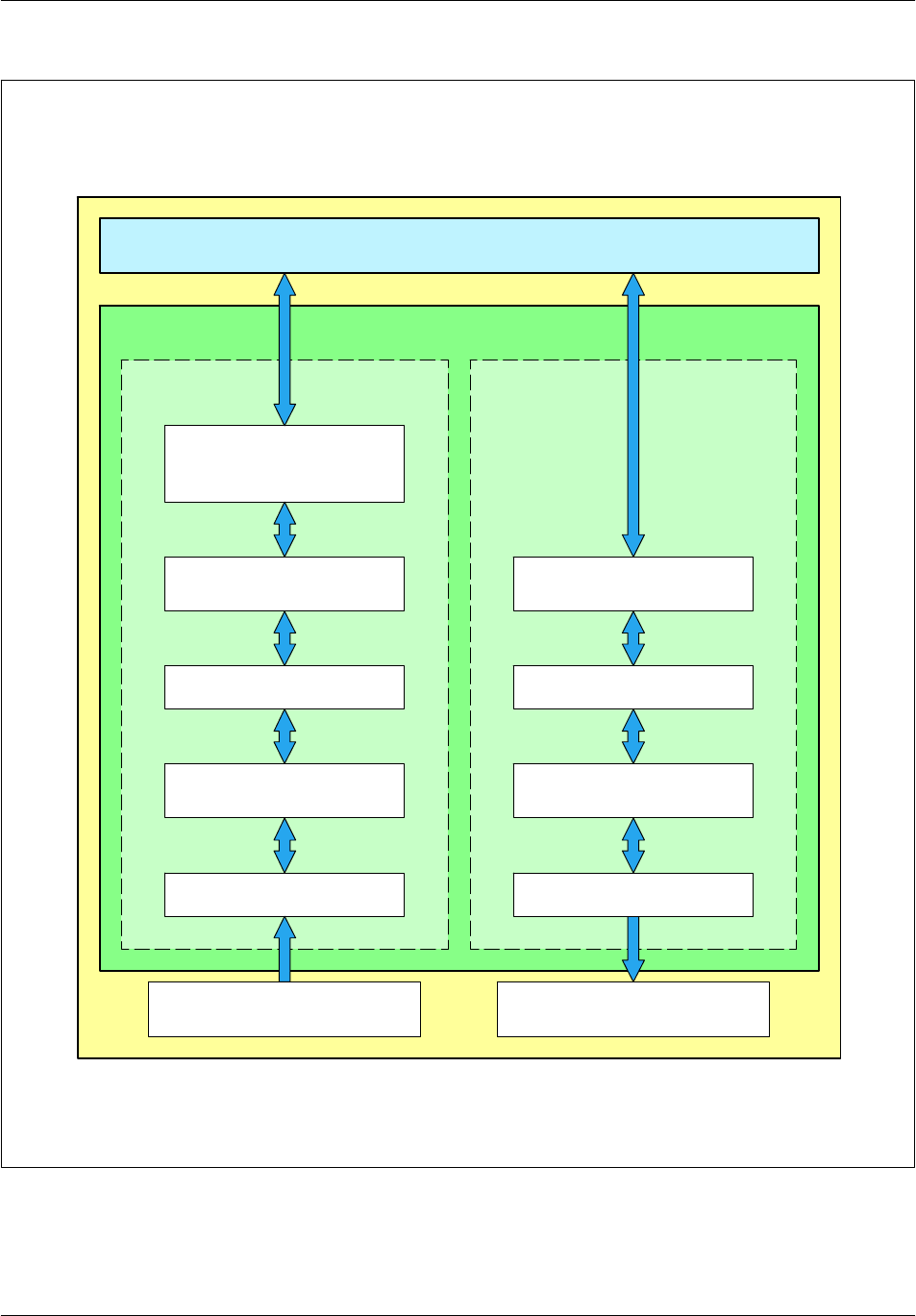
ArchitectureNortel Networks Confidential 3--47
S12000 BTS Reference Manual
Copyright ©2002--2005 Nortel Networks
Amplification RX module
(LNA--Splitter)
Amplification TX module
(LPA)
Radio unit
(e--RDRX)
RX1 (RF)
RX2 analog--to--digital
converter
Logic unit (e--LDRX)
TX1 (RF)
Frequency translation
(IF/RF)
RX1 (IF) TX1 (IF)
RX radio
function
TX radio
function
Frequency translation
(LF/IF)
Frequency translation
(LF/IF)
Frequency translation
(IF/RF)
Figure 3--12 Radio unit (e--RDRX): functional unit

Architecture Nortel Networks Confidential
3--48
PE/DCL/DD/0142
411--9001--142 Standard 15.102/EN May 2005 Copyright ©2002--2005 Nortel Networks
PAGE INTENTIONALLY LEFT BLANK

Software descrIptionNortel Networks Confidential 4--1
S12000 BTS Reference Manual
Copyright ©2002--2005 Nortel Networks
4 SOFTWARE DESCRIPTION
4.1 BTS software presentation
BTS software is divided into downloadable files and an onboard PROM.
4.1.1 Downloadable files
The BSC downloads these files via the A--bis interface.
There are two sets of files: BCF and DRX. Each set is arranged in a file catalogue
that contain the list of files and the files themselves.
4.1.2 PROM
PROM
chips are read-only memory units used to store software.
They are all installed on all BTS equipment boards.
4.1.2.1 S12000 BTS CBCF Software
The software product associated with the boards and slaves of the CBCF Modules
are listed in Table 4--1.
Board Sofware product name Software product type
CBCF Module PE_CBCF_B
PE_CBCF_DLU0
Boot
DLU Code
CPCMI PE_CPCMI_E1
PE_CPCMI_T1
Load
Load
RECAL PE_RECAL Load
Table 4--1 CBCF software product names

Software descrIption Nortel Networks Confidential
4--2
PE/DCL/DD/0142
411--9001--142 Standard 15.102/EN May 2005 Copyright ©2002--2005 Nortel Networks
4.1.2.2 S12000 BTS family DRX Software
As listed in Table 4--2, the software products vary depending on whether the BCF
or CBCF is used in the BTS. DRX O&M software is used with the BCF. DRX
COAM is used with the CBCF or BCF from V12 onward.
Board Sofware product name Software product type
DRX O&M/COAM PE_AMNU_COAM_L
PE_AMNU_RSL_L
PE_AMNU_B
PE_SPU2G_EGAL1_L
PE_SPU2G_EGAL2_L
PE_SPU2G_1620_L
PE_SPU2G_BIST
PE_SPU2G_BIST_1620
PE_TX_L_COAM
PE_BDT_L
PE_TOOLS
O&M AMNU LOAD
RSL AMNU LOAD
AMNU BOOT
SPU EGAL1
SPU EGAL2
SPU 1620
BIST SPU
BIST SPU 1620
TX
BDT
PL TOOLS
DRX PE_AMNU_COAM_L
PE_AMNU_RSL_L_C
PE_AMNU_B
PE_SPU2G_16410_L
PE_TOOLS
O&M AMNU LOAD
RSL AMNU LOAD
AMNU BOOT
SPU 16410
PL TOOLS
Table 4--2 S12000 BTS family : DRX software product names

Software descrIptionNortel Networks Confidential 4--3
S12000 BTS Reference Manual
Copyright ©2002--2005 Nortel Networks
4.2 BTS software functions
BTS software is distributed among three major units (see Figure 4--1):
The DRX unit is designed to transmit and receive (modulate and demodulate)
and manage TDMA frames on the radio channel.
The CBCF manages its slave units:
•
CPCMI, RECAL, or DRX, CC8
The TIL unit is used for in--factory testing of the BTS, and to configure, control,
and supervise the BTS on site.
The following terms are used in this chapter:
BIST: Basic hardware self--test programs of a BTS subsystem subassembly.
These tests validate a subassembly intrinsically, without disturbing the other
subassemblies. An example is the AMNU BIST, which tests the components
(such as memory) of the AMNU unit on the
DRX
logical board.
Self--tests: Global, functional test programs, which use several subassemblies in
order to validate an assembly (such as the DRX). These tests can be broken down
into tests of more or less elementary functions. This may require external
equipment (so the term may be misleading).
Downloading: A process which consists of installing, in the DRX (logical part),
software from an external entity (terminal, Ethernet network, BSC, etc.).
Loading: A process used to load, into the subassemblies of the DRX (logical
part), the software it requires for its nominal operation.
4.2.1 DRX software functions
The DRX is downloaded by the BSC, configured and supervised by the BSC and
the CMCF (CBCF) through a LAPD link and a serial link. It serves as a gateway
between the radio channel and the BSC. It handles both signaling and voice for all
the logical channels carried by a given TDMA frame.
The module has four functions:
The AMNU (LAPDm, L3 RSL, L3 O&M) is the
DRXs
management unit.
The SPU is a gateway between the radio network and the BSC.
TX and RX manage radio transmission and transmission.
The BDT manages the GSM TIME.
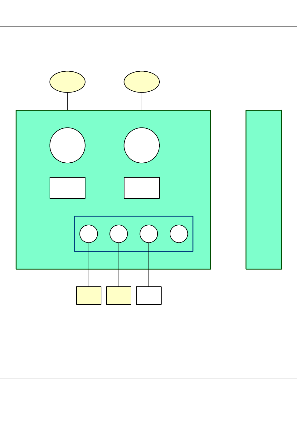
Software descrIption Nortel Networks Confidential
4--4
PE/DCL/DD/0142
411--9001--142 Standard 15.102/EN May 2005 Copyright ©2002--2005 Nortel Networks
TIL
OS
KERNEL
ABIS
O&M
KERNEL
O&M
specific
CBCF
Group of slave
managers
DRX
CPCMI
OS specific
(BSP)
RECAL
Group of slave
equipment
Figure 4--1 Software functions (with CBCF)

Software descrIptionNortel Networks Confidential 4--5
S12000 BTS Reference Manual
Copyright ©2002--2005 Nortel Networks
L3 O&M AMNU
This software unit centralizes the operating and maintenance functions:
initialitization and monitoring of BISTs
connection with Abis and BCF
downloading and software marking
configuration
defense and alarms
tool functions
transmission of GSM TIME to BDT, and of O&M to TX
L3 RSL
This software unit represents the Radio Resource (RR) and the radio measurements
function (L1M) in the BTS:
radio link layer management
dedicated channel management
common channel management
TRX management
error handling
measurement collecting
measurement pre--processing (for power control by the BTS, and for call
clearing and handover decision for the BSC)
LAPDm
This software unit provides the LAPDm radio level 2 protocol with the mobile.
SPU
This software unit enables the level 1 radio communication with the mobile to
transmit and receive:
gateway between radio and terrestrial network (Abis) for the traffic channel
multiplexing and demultiplexing of the logical channels on physical channels
RX
This software unit provides the radioelectrical reception function.

Software descrIption Nortel Networks Confidential
4--6
PE/DCL/DD/0142
411--9001--142 Standard 15.102/EN May 2005 Copyright ©2002--2005 Nortel Networks
L3 TX
This software unit manages and monitors radio transmission. It is installed in each
DRX
board. It sets the transmitter operation mode, defines the FH bus input from
which the TX should read data, and defines the transmission power to be used. It
also controls the Power Amplifier (PA).
L1 BDT
This software unit extracts the GSM TIME carried on the PCMp (GSM TIME TS)
for the BDT unit.
LAPD
This software unit manages the LAPD link level 2 protocol on PCM between DRX,
e--DRX, DRX--ND3 and BSC.
4.2.1.1 Network ID
With the implementation of V15.0, the BTS detects the type of DRX and PA during
connection with respect to the BCF and the DRX. Note the following restrictions:
If a DRX is not yet connected to the BCF, its type is set to “DRX type” until it is
connected.
If a PA is not yet connected to the DRX, its type is set to “PA type” until it is
connected.
If a fault beginning has been sent on the DRX type (or PA type) of equipment,
because the real equipment type was unknown, the fault ending must be sent on a
DRX or PA type, even if the DRX or PA have connected themselves between the
fault begin and fault end.
4.2.1.2 Defense
The DRX board carries out no defense actions by itself.

Software descrIptionNortel Networks Confidential 4--7
S12000 BTS Reference Manual
Copyright ©2002--2005 Nortel Networks
4.2.2 CBCF software functions
CBCF Software is based on a COAM software architecture, which is composed of
three main parts:
common software for various BTS products
•
OS Kernel
•
O&M Kernel
BTS--specific software dedicated to a BTS product
•
OS--specific
•
O&M--specific
slave managers
The COAM architecture is shown in Figure 4--2.
The CBCF software manages the following O&M functions:
PCM management
configuration and supervision management
software management
synchronization management
test management
duplex management
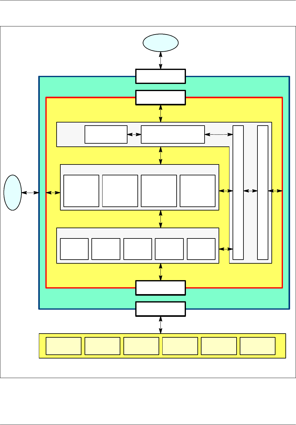
Software descrIption Nortel Networks Confidential
4--8
PE/DCL/DD/0142
411--9001--142 Standard 15.102/EN May 2005 Copyright ©2002--2005 Nortel Networks
Layer 2
Layer 3 access
Layer 2
Layer 3 access
Software
management Abis management
Equipment
manager
Connection
manager
Radio
resource
manager
Synchro
manager
Interlayer CBCF
Slave managers
DRX
manager
CPCMI
manager
RECAL
manager
S
c
h
e
d
u
l
e
r
D
u
p
l
e
x
M
a
n
a
g
e
r
O&M
kernel
CBCF
T
I
L
BSC
DRX
equipment
CPCMI
equipment
RECAL
equipment
Figure 4--2 COAM architecture on the CBCF

Software descrIptionNortel Networks Confidential 4--9
S12000 BTS Reference Manual
Copyright ©2002--2005 Nortel Networks
4.2.2.1 PCM Management
This function selects one of the incoming PCMs for communication with the BSC.
It then routes PCM TSs to the appropriate equipment in the BTS as the BSC
requests. Other PCM TSs are routed toward another PCM to allow drop & insert
functionality.
This function also ensures LAPD concentration.
4.2.2.2 Configuration and supervision management
This function translates the OML A--bis model into a physical model to offer a
standardized configuration and supervision to the BSC. The CBCF acts as an A--bis
front end toward the BSC for configuration and supervision purposes. It is the only
link for configuration messages coming from the BSC. The CBCF uses the CBCF/
DRX protocol to drive any actions concerning the DRX.
4.2.2.3 Software management
The CBCF performs software management for the BTS and provides the only link
for downloading messages from the BSC. When a RECAL or CPCMI board is
downloaded, the CBCF/Slave protocol is used.
4.2.2.4 Synchronization management
The CBCF builds the GSM time and provides it to the DRX, e--DRX, or DRX--ND3
via a TS or a private PCM. External PCMs ensure long term stability.
4.2.2.5 Test Management
The CBCF coordinates all BTS tests. When an installation or maintenance action
affects a
DRX
,the
DRX
is driven by the CBCF using the CBCF/DRX Protocol.
4.2.2.6 Duplex Management
The COAM software manages a cold and hot duplex modes.
4.2.3 Maintenance
The three types of customers include:
EDGE customer: function is necessary, because EDGE equipment must be
differentiated from non--EDGE equipment. An e--DRX must be replaced by an
e--DRX. An HePA must be replaced by an HePA.
Customer who uses an HePA or an e--HePA mixed cell in concentric cell: an
HePA must be replaced by an HePA, and an e--PA must be replaced by an e--PA. A
CMCF phase 2 must be replaced by a CMCF phase 2.

Software descrIption Nortel Networks Confidential
4--10
PE/DCL/DD/0142
411--9001--142 Standard 15.102/EN May 2005 Copyright ©2002--2005 Nortel Networks
Other customer: an e--DRX or a DRX ND3 can replace a failing DRX, an e--PA
(or an HePA) can replace a PA, if the number of the (H)(e)PA in the BTS respects
the HePA supported configurations. A CMCF phase 1 can replace a CMCF phase
2 (and vice versa), if the CMCF software is compatible with CMCF phase 1. No
mixing between phase 1 and phase 2.
4.2.4 TIL software functions
TIL is an application running on a PC in the WINDOWS 95 and WINDOWS 2000
environment. The TIL application is connected to the CBCF through an ethernet
connection.
The TIL is designed to do the following:
validate the BTS in the factory
install the BTS site
perform diagnostics of hardware problems
check equipment substitution
check the equipment extension within a cabinet
Ethernet
This unit is installed in the PC. It provides the level 1 and 2 communication layer.
Level 1 is a hardware driver. The level 2 protocol is an LAPD UI frame. TCP--IP
Protocol is used.
L3 TIL
This software unit manages all the boards of the BTS by establishment of a network
with all the GSM entities of the BTS. It integrates the factory and installation test
environment.
The TIL takes the following testing into consideration:
the conformity of the cabinet configuration
the validity of the data links
the external BTS PCM
the connectors in the cabinet for cabinet extensions

Dimensioning rulesNortel Networks Confidential 5--1
S12000 BTS Reference Manual
Copyright ©2002--2005 Nortel Networks
5 DIMENSIONING RULES
For information on dimensioning, refer to document GSM/GPRS/EDGE BSS
Engineering Rules (PE/DCL/DD/0138).

Dimensioning rules Nortel Networks Confidential
5--2
PE/DCL/DD/0142
411--9001--142 Standard 15.102/EN May 2005 Copyright ©2002--2005 Nortel Networks
PAGE INTENTIONALLY LEFT BLANK

Wireless Service Provider Solutions
S12000 BTS Reference Manual
Copyright ©2002--2005 Nortel Networks, All Rights Reserved
NORTEL NETWORKS CONFIDENTIAL:
The information contained in this document is the property of Nortel
Networks. Except as specifically authorized in writing by Nortel
Networks, the holder of this document shall keep the information
contained herein confidential and shall protect same in whole or in part
from disclosure and dissemination to third parties and use for evaluation,
operation and maintenance purposes only.
You may not reproduce, represent, or download through any means, the
information contained herein in any way or in any form without prior
written consent of Nortel Networks.
The following are trademarks of Nortel Networks: *NORTEL
NETWORKS, the NORTEL NETWORKS corporate logo, the NORTEL
Globemark, UNIFIED NETWORKS, S2000, S4000, S8000.
GSM is a trademark of France Telecom.
All other brand and product names are trademarks or registered
trademarks of their respective holders.
Publication Reference
PE/DCL/DD/0142 411--9001--142
15.102/EN
May 2005
Originated in France
For more information, please contact:
For all countries, except USA:
Documentation Department
Parc d’activité de Magny--Chateaufort
CHATEAUFORT
78928 YVELINES CEDEX 9
FRANCE
Email : gsmntp@nortelnetworks.com
Fax : (33) (1) 39--44--50--29
In the USA:
2221 Lakeside Boulevard
Richardson TX 75082
USA
Tel: 1--800--4 NORTEL
1--800--466--7838 or (972) 684--5935
Internet Address:
http://
www.nortelnetworks.com