Avaya Canada S8000 Base Transceiver Station User Manual EXHIBIT 11
Avaya Canada Corporation Base Transceiver Station EXHIBIT 11
UserManual.wiki
>
Avaya Canada
>
S8000 User Manual
Manual
Navigation menu
Upload a User Manual
Namespaces
Wiki Guide
HTML
PDF
Info
Views
User Manual
Discussion / Help
Navigation
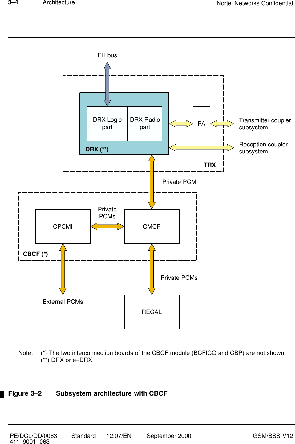
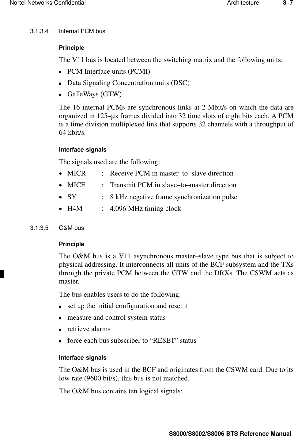
![Architecture Nortel Networks Confidential3–8PE/DCL/DD/0063411–9001–063 Standard 12.07/EN September 2000 GSM/BSS V12from master to slave:–TX : asynchronous data transmitted by the master–ADR[5..0]: six address lines giving the selected slave address from 00to 63–VAL : validation pulse, during which the address must be valid(negative pulse)–RAZ : initialization if this reset is pulsed during VAL pulse,inhibition if the VAL is pulsed during the RAZ (active atlow level)from slave to master:–RX : asynchronous data received by the masterEach slave receives from the back–panel six signals, NUC[5..0], that allows it todetermine its address and to compare to the ADR[5..0]address.](https://usermanual.wiki/Avaya-Canada/S8000/User-Guide-309749-Page-76.png)