Avaya Canada S8000 Base Transceiver Station User Manual EXHIBIT 11
Avaya Canada Corporation Base Transceiver Station EXHIBIT 11
Manual

This document contains Proprietary Information of Northern Telecom Limited. This information is
considered to be CONFIDENTIAL and should be treated appropriately.
EXHIBIT 11
Reference Manual
Applicant: Northern Telecom Ltd.
For Certification on:
AB6S8000

Wireless Service Provider Solutions
S8000 BTS
Reference Manual
PE/DCL/DD/0063 12.07/EN Standard September 2000
411–9001–063

< 63 > : S8000/S8002/S8006 BTS Reference Manual
Wireless Service Provider Solutions
S8000/S8002/S8006 BTS Reference
Manual
Document number: PE/DCL/DD/0063
411–9001–063
Document status: Standard
Document issue: 12.07/EN
Product release: GSM/BSS V12
Date: September 2000
Copyright 1996–2000 Nortel Networks, All Rights Reserved
Printed in France
NORTEL NETWORKS CONFIDENTIAL
The information contained in this document is the property of Nortel Networks. Except as specifically authorized in
writing by Nortel Networks, the holder of this document shall keep the information contained herein confidential and
shall protect same in whole or in part from disclosure and dissemination to third parties and use for evaluation,
operation and maintenance purposes only.
You may not reproduce, represent, or download through any means, the information contained herein in any way or in
any form without prior written consent of Nortel Networks.
The following are trademarks of Nortel Networks: *NORTEL NETWORKS, the NORTEL NETWORKS corporate logo,
the NORTEL Globemark, UNIFIED NETWORKS, S8000. GSM is a trademark of France Telecom.
All other brand and product names are trademarks or registred trademarks of their respective holders.

Publication HistoryNortel Networks Confidential iii
S8000/S8002/S8006 BTS Reference Manual
PUBLICATION HISTORY
System release: GSM/BSS V12
September 2000
Issue 12.07/EN Standard
Update after internal document review (PE/DCL/GES/0064 – 05.02/FR)
July 2000
Issue 12.06/EN Draft
S8006 BTS: Chapters 1, 2 ,4 , 5
S8000 family: Removal of the rectifier module evolution, chapter 2
Battery cabinet alarm cabling updated, chapter 2
TD 1158: Additional external alarms on CBCF, chapter 2
Dimensioning rule updated, chapter 5
CSR EE00608: EXT. P./ EXT. NP. pin connections on ALCO/RECAL boards
updated, chapter 2
June 2000
Issue 12.05/EN Preliminary
Modification of the manual structure
PR 1179 and PR 1163: Cavity coupling, chapters 1, 2, 3, 4
e–DRX module: all chapters
New PA, chapter 2
Tri–phase ac box (type 4), chapter 2
SR EE00198 or SR NK00810 CPCMI board: switch position, chapter 2
Power system: new type of six–rectifiers, chapter 2
Dimensioning rules and configurations updated, chapter 5
November 1999
Issue 12.04/EN Standard
Minor editorial update

Publication History Nortel Networks Confidential
iv
PE/DCL/DD/0063
411–9001–063 Standard 12.07/EN September 2000 GSM/BSS V12
November 1999
Issue 12.03/EN Standard
Translation according to the V12.02/FR updating
June 1999
Issue 12.02/EN Preliminary
Update according to the review report, PE/DCL/GES/0064 V05.01/FR.
May 1999
Issue 12.01/EN Draft
Update for the V12 release according to the “Feature list of System Release V12”,
(PE/SYS/DPL/103 V01.04/EN), chapters 3 and 6
PR 887: S8000 Indoor 900/1800 (2D+H2D or 2H2D), chapter 6
PR 897 : S8000 Outdoor 900/1800/1900 (2D+H2D or 2H2D), chapter 6
PR 942 : S8000 Outdoor 900, 1800 (H2D or H4D), chapter 6
SR 301 06261: Connector description, chapter 4
S8002 BTS

Publication HistoryNortel Networks Confidential v
S8000/S8002/S8006 BTS Reference Manual
SYSTEM RELEASE : GSM/BSS V11
November 1999
Issue 11.04/EN
Update for the V11 release according to the SR EE90852 : Add the switch S3 on
the CPCMI board
May 1999
Issue 11.03/EN
Introduction of S8002 BTS
Refer to review report of PE/DCL/0064/ V05.01/FR
September 1998
Issue 11.02/EN
Update after internal document review (PE/DCL/GES/0064 V04.01/FR).
September 1998
Issue 11.01/EN
Update for the V11 release according to the “Feature list of System Release V11”
(PE/SYS/DPL/0089 V01.02/EN)
EC 101–2447: Change in level of power consumption for S8000 Outdoor BTS
(GSM 1900 only), chapter 3
PR 549, 807: CBCF for S8000I 900/1800
PR 776, 834: CBCF for S8000O 900/1800/1900
PR 907 S8000 I/O 3S888 H2D 900/1800, chapter 3 and 6
PR 967 S8000 I/O 016 H4D 900/1800, chapter 3 and 6
Addition of the single phase AC box, type 1, chapter 3
Addition of the tri–phase AC box, type 2, chapter 3

Publication History Nortel Networks Confidential
vi
PE/DCL/DD/0063
411–9001–063 Standard 12.07/EN September 2000 GSM/BSS V12
SYSTEM RELEASE : GSM/BSS V10
November 1999
Issue 10.06/EN
Update for the V10 release according to the SR EE90852 : Add the switch S3 on
the CPCMI board
June 1999
Issue 10.05/EN
See report review PE/DCL/GES/0064, V05.01/FR except S8002 BTS comments
May 1999
Issue 10.04/EN
Same issue as 11.01/EN
April 1998
Issue 10.03/EN
After review report PE/DCL/GES/0064, V03.02/FR, chapters 2, 3, 4 and 6
March 1998
Issue 10.02/EN
SR 30080371: DSC board dimensioning, chapter 6
PR 740, 741, 767: Tx–Filter, chapters 2, 3, 4 and 6
PR 742, 770, 771: DRX New Design, chapters 3 and 4
PR 896, S8000 I/O Dual band configuration 3S444–444 (H2D), chapter 3
Removal of J64 connector (GTW board), chapter 4
New 75 Ω box, chapter 3
February 1998
Issue 10.01/EN
Update for V10 release according to “Feature List of system release”
PE/SYS/DPL/0075, V01.03/EN.
AR329, PF471: dual band configuration, chapter 6
After review report PE/DCL/GES/64 V03.01/FR.

Publication HistoryNortel Networks Confidential vii
S8000/S8002/S8006 BTS Reference Manual
SYSTEM RELEASE : GSM/BSS V09
February 1998
Issue 09.09/EN
After review report PE/DCL/GES/64, V02.04/FR, chapters 3, 4, 5 and 6.
February 1998
Issue 09.08/EN
Update for V9 release:
PR 485/623/486: S8000 Outdoor extension introduction, chapters 3 and 6
PR742: DRX new design, chapter 4
CM743: interferer cancellation on DRX, chapter 2
PR740/767/741: new configuration with duplexer coupling, chapter 3 and 6
New configuration with H4D coupling, chapter 6
DRX LEDs meaning, chapter 3
Cabling figures enhanced, chapter 1
FCC label location corrected, chapter 3
LEDs of climatic system introduced, chapters 3 and 4
RF combiner board enhanced, chapter 3
Additional equipment introduced (–48V kit, phone plug kit...), chapter 6
SR 30080371: DSC board dimensioning, chapter 6
November 1997
Issue 09.07/EN
After review report PE/DCL/GES/64, V02.03/FR, chapters 3, 4 and 6
October 1997
Issue 09.06/EN
Update for V9 release according to “Feature list of system release”
PE/SYS/DPL/0057, V01.07/EN:
New Power System (7–rectifier type), chapters 3 and 4
PR520/521: S8000 Indoor extension cabinet (GSM 900/1800), chapters 3, 4
and 6

Publication History Nortel Networks Confidential
viii
PE/DCL/DD/0063
411–9001–063 Standard 12.07/EN September 2000 GSM/BSS V12
PR738: New RF combiner with H4D coupling, chapters 3, 4 and 6
Cross Polarization configurations, chapters 3 and 6
Internal remarks
Addition of BCF TEI configuration, chapter 4
Addition of regulatory information, chapter 1
August 1997
Issue 09.05/EN
DACS introduction in S8000 Outdoor BTS, chapter 3
July 1997
Issue 09.04/EN
After review report PE/DCL/GES/64, V02.02/FR.
June 1997
Issue 09.03/EN
Update for V9 release according to “Feature list of system release”
PE/SYS/DPL/0057, V01.06/EN
TF 441 Power Control Enhancements, chapter 2
BCF configurations, chapter 2
RX–Splitter gain value, chapter 4
DRX receive sensitivity, chapter 4
March 1997
Issue 09.02/EN
After review report PE/DCL/GES/064, V02.01/FR.

Publication HistoryNortel Networks Confidential ix
S8000/S8002/S8006 BTS Reference Manual
February 1997
Issue 09.01/EN
Reorganisation of the volume for V9 release.
Update for V9 release according to “Feature list of system release”
PE/SYS/DPL/0057, V01.05/EN:
PR276, PR465, PR484: S8000 Outdoor BTS 900
FM 625: RX–Splitter alarm on S8000, chapters 2
S8000 Indoor: New Product
CM 330: Cell Soft Blocking improvement, chapter 2
TF 225: Forced Hardover, chapter 2
Former versions document obsolete BSS system versions. Therefore, the publication history
is not applicable.

Publication History Nortel Networks Confidential
x
PE/DCL/DD/0063
411–9001–063 Standard 12.07/EN September 2000 GSM/BSS V12
PAGE INTENTIONALLY LEFT BLANK

Table of contents
Nortel Networks Confidential xi
S8000/S8002/S8006 BTS Reference Manual
About this document xxv. . . . . . . . . . . . . . . . . . . . . . . . . . . . . . . . . . . . . . . . . . . . . . .
Applicability xxv. . . . . . . . . . . . . . . . . . . . . . . . . . . . . . . . . . . . . . . . . . . . . . . . . . . . . . . . . . . . . . . . . . . . . .
Precautionary message xxv. . . . . . . . . . . . . . . . . . . . . . . . . . . . . . . . . . . . . . . . . . . . . . . . . . . . . . . .
Audience xxv. . . . . . . . . . . . . . . . . . . . . . . . . . . . . . . . . . . . . . . . . . . . . . . . . . . . . . . . . . . . . . . . . . . . . . . .
Prerequisites xxv. . . . . . . . . . . . . . . . . . . . . . . . . . . . . . . . . . . . . . . . . . . . . . . . . . . . . . . . . . . . . . . . . . . .
Related Document xxvi. . . . . . . . . . . . . . . . . . . . . . . . . . . . . . . . . . . . . . . . . . . . . . . . . . . . . . . . . . . . . . . .
How this document is organized xxvi. . . . . . . . . . . . . . . . . . . . . . . . . . . . . . . . . . . . . . . . . . . . . . . . . . . .
Regulatory information xxvi. . . . . . . . . . . . . . . . . . . . . . . . . . . . . . . . . . . . . . . . . . . . . . . . . . . . . . . . . . . .
1 Cabinet description 1–1. . . . . . . . . . . . . . . . . . . . . . . . . . . . . . . . . . . . . . . .
1.1 Physical characteristics 1–1. . . . . . . . . . . . . . . . . . . . . . . . . . . . . . . . . . . . . . . . . . . . . . . . . .
1.1.1 S8000 Outdoor BTS 1–1. . . . . . . . . . . . . . . . . . . . . . . . . . . . . . . . . . . . . . . . . . .
1.1.2 S8000 Indoor BTS 1–16. . . . . . . . . . . . . . . . . . . . . . . . . . . . . . . . . . . . . . . . . . . .
1.1.5 Product names 1–27. . . . . . . . . . . . . . . . . . . . . . . . . . . . . . . . . . . . . . . . . . . . . . .
1.1.6 Configurations 1–27. . . . . . . . . . . . . . . . . . . . . . . . . . . . . . . . . . . . . . . . . . . . . . . .
1.2 Cabinet compartment layout 1–29. . . . . . . . . . . . . . . . . . . . . . . . . . . . . . . . . . . . . . . . . . . . . .
1.2.1 S8000 Outdoor BTS 1–29. . . . . . . . . . . . . . . . . . . . . . . . . . . . . . . . . . . . . . . . . . .
1.2.2 S8000 Indoor BTS 1–35. . . . . . . . . . . . . . . . . . . . . . . . . . . . . . . . . . . . . . . . . . . .
1.2.5 Additional equipments 1–50. . . . . . . . . . . . . . . . . . . . . . . . . . . . . . . . . . . . . . . . .
1.3 BTS cabling 1–60. . . . . . . . . . . . . . . . . . . . . . . . . . . . . . . . . . . . . . . . . . . . . . . . . . . . . . . . . . . .
1.3.1 Connector plates 1–60. . . . . . . . . . . . . . . . . . . . . . . . . . . . . . . . . . . . . . . . . . . . . .
1.3.2 Internal cabling 1–66. . . . . . . . . . . . . . . . . . . . . . . . . . . . . . . . . . . . . . . . . . . . . . .
1.3.3 External cabling 1–100. . . . . . . . . . . . . . . . . . . . . . . . . . . . . . . . . . . . . . . . . . . . . . .
1.3.4 Inter–cabinet cabling 1–100. . . . . . . . . . . . . . . . . . . . . . . . . . . . . . . . . . . . . . . . . . .
1.4 Power supply 1–136. . . . . . . . . . . . . . . . . . . . . . . . . . . . . . . . . . . . . . . . . . . . . . . . . . . . . . . . . . .
1.4.1 S8000 Outdoor 1–136. . . . . . . . . . . . . . . . . . . . . . . . . . . . . . . . . . . . .
1.4.2 S8000 Indoor BTS 1–161. . . . . . . . . . . . . . . . . . . . . . . . . . . . . . . . . . . . . . . . . . . .

Table of contents
Nortel Networks Confidential xiii
S8000/S8002/S8006 BTS Reference Manual
3 Architecture 3–1. . . . . . . . . . . . . . . . . . . . . . . . . . . . . . . . . . . . . . . . . . . . . . .
3.1 Physical architecture 3–1. . . . . . . . . . . . . . . . . . . . . . . . . . . . . . . . . . . . . . . . . . . . . . . . . . . .
3.1.1 Introduction 3–1. . . . . . . . . . . . . . . . . . . . . . . . . . . . . . . . . . . . . . . . . . . . . . . . . .
3.1.2 Subsystems 3–1. . . . . . . . . . . . . . . . . . . . . . . . . . . . . . . . . . . . . . . . . . . . . . . . . .
3.1.3 Internal buses 3–1. . . . . . . . . . . . . . . . . . . . . . . . . . . . . . . . . . . . . . . . . . . . . . . .
3.2 BCF functional architecture 3–9. . . . . . . . . . . . . . . . . . . . . . . . . . . . . . . . . . . . . . . . . . . . . .
3.2.1 BCF control, switching and management (CSWM) 3–9. . . . . . . . . . . . . . . . .
3.2.2 Data Signaling Concentration unit (DSC) 3–16. . . . . . . . . . . . . . . . . . . . . . . . .
3.2.3 PCM Interface (PCMI) 3–18. . . . . . . . . . . . . . . . . . . . . . . . . . . . . . . . . . . . . . . . .
3.2.4 Synchronization (SYNC) 3–20. . . . . . . . . . . . . . . . . . . . . . . . . . . . . . . . . . . . . . .
3.2.5 Alarm collecting function (ALCO) 3–22. . . . . . . . . . . . . . . . . . . . . . . . . . . . . . . .
3.2.6 BCF/DRX gateway (GTW) 3–22. . . . . . . . . . . . . . . . . . . . . . . . . . . . . . . . . . . . . .
3.2.7 BCF configurations 3–24. . . . . . . . . . . . . . . . . . . . . . . . . . . . . . . . . . . . . . . . . . . .

Table of contents Nortel Networks Confidential
xiv
PE/DCL/DD/0063
411–9001–063 Standard 12.07/EN September 2000 GSM/BSS V12
3.3 CBCF functional architecture 3–25. . . . . . . . . . . . . . . . . . . . . . . . . . . . . . . . . . . . . . . . . . . . .
3.3.1 Switching, synchronization, and concentration 3–25. . . . . . . . . . . . . . . . . . . . .
3.3.2 Control of the alarm management unit 3–29. . . . . . . . . . . . . . . . . . . . . . . . . . .
3.3.3 PCM Interface 3–29. . . . . . . . . . . . . . . . . . . . . . . . . . . . . . . . . . . . . . . . . . . . . . . .
3.4 DRX functional architecture 3–31. . . . . . . . . . . . . . . . . . . . . . . . . . . . . . . . . . . . . . . . . . . . . .
3.4.1 DRX digital part 3–31. . . . . . . . . . . . . . . . . . . . . . . . . . . . . . . . . . . . . . . . . . . . . . .
3.4.2 DRX radio part 3–47. . . . . . . . . . . . . . . . . . . . . . . . . . . . . . . . . . . . . . . . . . . . . . . .
3.4.3 DRX shutting down 3–48. . . . . . . . . . . . . . . . . . . . . . . . . . . . . . . . . . . . . . . . . . . .
3.4.4 Power supply board 3–49. . . . . . . . . . . . . . . . . . . . . . . . . . . . . . . . . . . . . . . . . . .
3.5 e–DRX functional architecture 3–50. . . . . . . . . . . . . . . . . . . . . . . . . . . . . . . . . . . . . . . . . . . .
3.5.1 Modifications between the DRX and e–DRX 3–50. . . . . . . . . . . . . . . . . . . . . .
3.5.2 Main external connections 3–52. . . . . . . . . . . . . . . . . . . . . . . . . . . . . . . . . . . . . .
3.5.3 e–DRX functional description 3–53. . . . . . . . . . . . . . . . . . . . . . . . . . . . . . . . . . .
4 Software descrIption 4–1. . . . . . . . . . . . . . . . . . . . . . . . . . . . . . . . . . . . . . .
4.1 BTS software presentation 4–1. . . . . . . . . . . . . . . . . . . . . . . . . . . . . . . . . . . . . . . . . . . . . . .
4.1.1 Downloadable files 4–1. . . . . . . . . . . . . . . . . . . . . . . . . . . . . . . . . . . . . . . . . . . .
4.1.2 PROM 4–1. . . . . . . . . . . . . . . . . . . . . . . . . . . . . . . . . . . . . . . . . . . . . . . . . . . . . . .
4.2 BTS software functions 4–6. . . . . . . . . . . . . . . . . . . . . . . . . . . . . . . . . . . . . . . . . . . . . . . . . .
4.2.1 DRX or e–DRX software functions 4–6. . . . . . . . . . . . . . . . . . . . . . . . . . . . . . .
4.2.2 BCF software functions 4–10. . . . . . . . . . . . . . . . . . . . . . . . . . . . . . . . . . . . . . . .
4.2.3 CBCF software functions 4–12. . . . . . . . . . . . . . . . . . . . . . . . . . . . . . . . . . . . . . .
4.2.4 TIL software functions 4–15. . . . . . . . . . . . . . . . . . . . . . . . . . . . . . . . . . . . . . . . .
5 Dimensioning rules 5–1. . . . . . . . . . . . . . . . . . . . . . . . . . . . . . . . . . . . . . . .
5.1 Generalities on dimensioning 5–1. . . . . . . . . . . . . . . . . . . . . . . . . . . . . . . . . . . . . . . . . . . . .
5.1.1 RADIO interface dimensions 5–1. . . . . . . . . . . . . . . . . . . . . . . . . . . . . . . . . . . .
5.1.2 Abis Interface dimensioning 5–4. . . . . . . . . . . . . . . . . . . . . . . . . . . . . . . . . . . .
5.2 Dimensioning of the BTS 5–7. . . . . . . . . . . . . . . . . . . . . . . . . . . . . . . . . . . . . . . . . . . . . . . .
5.2.1 Configurations 5–7. . . . . . . . . . . . . . . . . . . . . . . . . . . . . . . . . . . . . . . . . . . . . . . .
5.2.2 Dimensioning of radio and Abis interfaces 5–8. . . . . . . . . . . . . . . . . . . . . . . .
5.2.3 Dimensioning of DSC board (with BCF) 5–9. . . . . . . . . . . . . . . . . . . . . . . . . .
5.3 Configurations 5–9. . . . . . . . . . . . . . . . . . . . . . . . . . . . . . . . . . . . . . . . . . . . . . . . . . . . . . . . . .

List of figures
Nortel Networks Confidential xv
S8000/S8002/S8006 BTS Reference Manual
Figure 1–1 S8000 Outdoor BTS with ACU climatic system 1–3. . . . . . . . . . . . . . . . . . . . . . . . .
Figure 1–2 S8000 Outdoor BTS: Air circulation in the BTS with ACUs 1–4. . . . . . . . . . . . . . .
Figure 1–3 S8000 Outdoor BTS: ACU climatic system diagram 1–5. . . . . . . . . . . . . . . . . . . . .
Figure 1–4 S8000 Outdoor BTS with DACS climatic system 1–7. . . . . . . . . . . . . . . . . . . . . . .
Figure 1–5 S8000 Outdoor BTS: Air circulation in the BTS with DACS or
“LN” DACS 1–8. . . . . . . . . . . . . . . . . . . . . . . . . . . . . . . . . . . . . . . . . . . . . . . . . . . . . . . .
Figure 1–6 S8000 Outdoor BTS with “LN” DACS climatic system 1–10. . . . . . . . . . . . . . . . . . .
Figure 1–7 Control board of climatic system with “LN” DACS 1–12. . . . . . . . . . . . . . . . . . . . . . .
Figure 1–8 S8000 Outdoor BTS: Plinth diagram 1–15. . . . . . . . . . . . . . . . . . . . . . . . . . . . . . . . . .
Figure 1–9 S8000 Indoor BTS: Base cabinet 1–17. . . . . . . . . . . . . . . . . . . . . . . . . . . . . . . . . . . . .
Figure 1–10 S8000 Indoor BTS: BCF cabinet 1–18. . . . . . . . . . . . . . . . . . . . . . . . . . . . . . . . . . . . .
Figure 1–11 S8002 BTS: Base cabinet layout 1–20. . . . . . . . . . . . . . . . . . . . . . . . . . . . . . . . . . . . .
Figure 1–12 S8006 BTS: Base cabinet layout 1–23. . . . . . . . . . . . . . . . . . . . . . . . . . . . . . . . . . . . .
Figure 1–13 S8000 Outdoor BTS: Base cabinet layout (with BCF) 1–30. . . . . . . . . . . . . . . . . . . .
Figure 1–14 S8000 Outdoor BTS: Base cabinet layout (with CBCF) 1–31. . . . . . . . . . . . . . . . . .
Figure 1–15 S8000 Outdoor BTS: Extension cabinet layout 1–32. . . . . . . . . . . . . . . . . . . . . . . . .
Figure 1–16 S8000 Indoor BTS: Base cabinet layout 1–36. . . . . . . . . . . . . . . . . . . . . . . . . . . . . . .
Figure 1–17 S8000 Indoor BTS: BCF cabinet layout 1–39. . . . . . . . . . . . . . . . . . . . . . . . . . . . . . . .
Figure 1–18 S8000 Indoor BTS: BCF cabinet top view 1–40. . . . . . . . . . . . . . . . . . . . . . . . . . . . . .
Figure 1–19 BCF back panel 1–42. . . . . . . . . . . . . . . . . . . . . . . . . . . . . . . . . . . . . . . . . . . . . . . . . . . .
Figure 1–20 Localizing device 1–43. . . . . . . . . . . . . . . . . . . . . . . . . . . . . . . . . . . . . . . . . . . . . . . . . . .
Figure 1–21 S8002 BTS layout 1–45. . . . . . . . . . . . . . . . . . . . . . . . . . . . . . . . . . . . . . . . . . . . . . . . . .
Figure 1–22 S8006 BTS layout 1–48. . . . . . . . . . . . . . . . . . . . . . . . . . . . . . . . . . . . . . . . . . . . . . . . . .
Figure 1–23 External battery cabinet for S8000 Outdoor BTS (type 1) 1–51. . . . . . . . . . . . . . . .
Figure 1–24 External battery cabinet for S8000 Outdoor BTS (type 2) 1–52. . . . . . . . . . . . . . . .
Figure 1–25 S8000 Indoor BTS: Cabinet top 1–54. . . . . . . . . . . . . . . . . . . . . . . . . . . . . . . . . . . . . .
Figure 1–26 S8000/S8002/S8006 Outdoor: 75 ohms box type 1 1–55. . . . . . . . . . . . . . . . . . . . .
Figure 1–27 S8000/S8002/S8006 Outdoor: 75 ohms box type 2 1–56. . . . . . . . . . . . . . . . . . . . .
Figure 1–28 S8000/S8002/S8006 Outdoor BTS: PCM connection box 1–57. . . . . . . . . . . . . . . .
Figure 1–29 S8000/S8002/S8006 Outdoor BTS: –48 V connection box 1–58. . . . . . . . . . . . . . .
Figure 1–30 External alarm connection box 1–59. . . . . . . . . . . . . . . . . . . . . . . . . . . . . . . . . . . . . . .
Figure 1–31 Antenna connectors for various coupling systems
(maximum configurations) 1–61. . . . . . . . . . . . . . . . . . . . . . . . . . . . . . . . . . . . . . . . . . .
Figure 1–32 S8000 Outdoor BTS: Connector plates 1–62. . . . . . . . . . . . . . . . . . . . . . . . . . . . . . . .
Figure 1–33 S8000 Indoor BTS: External top connection kit 1–63. . . . . . . . . . . . . . . . . . . . . . . . .
Figure 1–34 S8002 Outdoor BTS bulkhead plates 1–65. . . . . . . . . . . . . . . . . . . . . . . . . . . . . . . . . .

List of figures Nortel Networks Confidential
xvi
PE/DCL/DD/0063
411–9001–063 Standard 12.07/EN September 2000 GSM/BSS V12
Figure 1–35 S8006 BTS: Connectors 1–65. . . . . . . . . . . . . . . . . . . . . . . . . . . . . . . . . . . . . . . . . . . .
Figure 1–36 S8000 Indoor/ Outdoor BTS interconnection panels 1–67. . . . . . . . . . . . . . . . . . . . .
Figure 1–37 S8002 Outdoor interconnection panel 1–68. . . . . . . . . . . . . . . . . . . . . . . . . . . . . . . . .
Figure 1–38 S8006 BTS: Interconnection panels 1–69. . . . . . . . . . . . . . . . . . . . . . . . . . . . . . . . . . .
Figure 1–39 Transmission/reception diagram for a 1O2 configuration with
duplexer coupling system 1–71. . . . . . . . . . . . . . . . . . . . . . . . . . . . . . . . . . . . . . . . . . . .
Figure 1–40 S8002 BTS: Cabling for a 1O2 configuration with duplexer
coupling system 1–72. . . . . . . . . . . . . . . . . . . . . . . . . . . . . . . . . . . . . . . . . . . . . . . . . . . .
Figure 1–41 Transmission/reception diagram for a 1S211 configuration
with duplexer coupling system 1–73. . . . . . . . . . . . . . . . . . . . . . . . . . . . . . . . . . . . . . .
Figure 1–42 S8000 Outdoor BTS (base cabinet): Cabling for a 1S211
configuration with duplexer coupling system 1–74. . . . . . . . . . . . . . . . . . . . . . . . . . . .
Figure 1–43 S8000 Indoor BTS: Cabling for a 1S211 configuration with
duplexer coupling system 1–75. . . . . . . . . . . . . . . . . . . . . . . . . . . . . . . . . . . . . . . . . . . .
Figure 1–44 Transmission/reception for a S222 configuration with H2D
coupling system 1–76. . . . . . . . . . . . . . . . . . . . . . . . . . . . . . . . . . . . . . . . . . . . . . . . . . . .
Figure 1–45 Transmission/reception for a 2S433 configuration with H2D
coupling system 1–77. . . . . . . . . . . . . . . . . . . . . . . . . . . . . . . . . . . . . . . . . . . . . . . . . . . .
Figure 1–46 S8006 BTS: Cabling for a S222 configuration using H2D
coupling system 1–78. . . . . . . . . . . . . . . . . . . . . . . . . . . . . . . . . . . . . . . . . . . . . . . . . . . .
Figure 1–47 S8000 Outdoor BTS (base cabinet): Cabling for a 2S433
configuration using H2D coupling system 1–79. . . . . . . . . . . . . . . . . . . . . . . . . . . . . .
Figure 1–48 S8000 Outdoor BTS (extension cabinet): Cabling for a 2S433
configuration using H2D coupling system 1–80. . . . . . . . . . . . . . . . . . . . . . . . . . . . . .
Figure 1–49 S8000 Indoor BTS: Cabling for a 2S433 configuration using H2D
coupling system 1–81. . . . . . . . . . . . . . . . . . . . . . . . . . . . . . . . . . . . . . . . . . . . . . . . . . . .
Figure 1–50 Transmission/reception diagram for a 1O8 configuration using H2D
coupling system and four antennas 1–82. . . . . . . . . . . . . . . . . . . . . . . . . . . . . . . . . . .
Figure 1–51 S8000 Outdoor BTS (base cabinet): Cabling for a 1O8 configuration
using H2D coupling system and four antennas 1–83. . . . . . . . . . . . . . . . . . . . . . . . .
Figure 1–52 S8000 Indoor BTS: Cabling for a 1O8 configuration using H2D
coupling system and four antennas 1–84. . . . . . . . . . . . . . . . . . . . . . . . . . . . . . . . . . .
Figure 1–53 Transmission/reception diagram for a 1O8 configuration using H4D
coupling system 1–85. . . . . . . . . . . . . . . . . . . . . . . . . . . . . . . . . . . . . . . . . . . . . . . . . . . .
Figure 1–54 S8000 Outdoor BTS (base cabinet): Cabling for a 1O8 configuration
using H4D coupling system 1–86. . . . . . . . . . . . . . . . . . . . . . . . . . . . . . . . . . . . . . . . . .
Figure 1–55 S8000 Indoor BTS (base cabinet): Cabling for a 1O8 configuration
using H4D coupling system 1–87. . . . . . . . . . . . . . . . . . . . . . . . . . . . . . . . . . . . . . . . . .
Figure 1–56 Transmission/reception diagram for 1O8 configuration using duplexer
and cavity system coupling 1–88. . . . . . . . . . . . . . . . . . . . . . . . . . . . . . . . . . . . . . . . . .
Figure 1–57 S8000 Indoor BTS (base cabinet): Cabling for 1O8 configuration using
duplexer and cavity coupling system 1–89. . . . . . . . . . . . . . . . . . . . . . . . . . . . . . . . . .

List of figures
Nortel Networks Confidential xvii
S8000/S8002/S8006 BTS Reference Manual
Figure 1–58 S8000 Indoor BTS (base cabinet): Cabling for a 2S444 configuration
using duplexer and Tx–Filter coupling system 1–90. . . . . . . . . . . . . . . . . . . . . . . . . .
Figure 1–59 S8000 Outdoor BTS: Cabling for a 1S44 configuration using duplexer
and Tx–Filter coupling system 1–91. . . . . . . . . . . . . . . . . . . . . . . . . . . . . . . . . . . . . . . .
Figure 1–60 S8000 Indoor BTS (base cabinet): Cabling for a 3S444–444 dual
band configuration using H2D coupling system 1–92. . . . . . . . . . . . . . . . . . . . . . . . .
Figure 1–61 S8000 Indoor BTS (extension cabinets): Cabling for a 3S444–444
dual band configuration using H2D coupling system 1–93. . . . . . . . . . . . . . . . . . . . .
Figure 1–62 S8000 Indoor BTS (base cabinet): Cabling for a 3S444–222 dual band
configuration using D and H2D coupling system 1–94. . . . . . . . . . . . . . . . . . . . . . . .
Figure 1–63 S8000 Indoor BTS (extension cabinet): Cabling for a 3S444–222 dual
band configuration using D and H2D coupling system 1–95. . . . . . . . . . . . . . . . . . .
Figure 1–64 S8000 Indoor BTS (base cabinets): Cabling for a 3S666 configuration
using D and H2D coupling system 1–96. . . . . . . . . . . . . . . . . . . . . . . . . . . . . . . . . . . .
Figure 1–65 S8000 Indoor BTS (extension cabinets): Cabling for a 3S666 configuration
using D and H2D coupling system 1–97. . . . . . . . . . . . . . . . . . . . . . . . . . . . . . . . . . .
Figure 1–66 Transmission/reception diagram for a 3S888 configuration using duplexer
and cavity coupling system 1–98. . . . . . . . . . . . . . . . . . . . . . . . . . . . . . . . . . . . . . . . . .
Figure 1–67 S8000 Indoor BTS (base cabinet): Cabling for a 3S888 configuration
using duplexer and cavity coupling system 1–99. . . . . . . . . . . . . . . . . . . . . . . . . . . . .
Figure 1–68 S8000 Outdoor BTS: ac and dc cabling 1–101. . . . . . . . . . . . . . . . . . . . . . . . . . . . . . .
Figure 1–69 S8000 Indoor BTS: ac and dc cabling 1–102. . . . . . . . . . . . . . . . . . . . . . . . . . . . . . . . .
Figure 1–70 S8002 BTS: ac and dc cabling 1–103. . . . . . . . . . . . . . . . . . . . . . . . . . . . . . . . . . . . . . .
Figure 1–71 S8006 BTS: ac and dc cabling 1–104. . . . . . . . . . . . . . . . . . . . . . . . . . . . . . . . . . . . . . .
Figure 1–72 S8000 Outdoor BTS: Ground cabling 1–105. . . . . . . . . . . . . . . . . . . . . . . . . . . . . . . . .
Figure 1–73 S8000 Indoor BTS: Ground cabling 1–106. . . . . . . . . . . . . . . . . . . . . . . . . . . . . . . . . . .
Figure 1–74 S8002 BTS: Ground cabling 1–107. . . . . . . . . . . . . . . . . . . . . . . . . . . . . . . . . . . . . . . . .
Figure 1–75 S8006 BTS: Ground cabling 1–108. . . . . . . . . . . . . . . . . . . . . . . . . . . . . . . . . . . . . . . . .
Figure 1–76 S8000 Outdoor BTS: External alarm cabling 1–109. . . . . . . . . . . . . . . . . . . . . . . . . . .
Figure 1–77 S8000 Indoor BTS: External alarm cabling (with CBCF) 1–110. . . . . . . . . . . . . . . . .
Figure 1–78 S8000 Indoor BTS: External alarm cabling (with BCF) 1–111. . . . . . . . . . . . . . . . . . .
Figure 1–79 S8006 BTS: External alarm cabling 1–112. . . . . . . . . . . . . . . . . . . . . . . . . . . . . . . . . . .
Figure 1–80 S8000 Outdoor BTS: Internal alarm cabling 1–113. . . . . . . . . . . . . . . . . . . . . . . . . . . .
Figure 1–81 S8002 BTS: Alarm cabling 1–114. . . . . . . . . . . . . . . . . . . . . . . . . . . . . . . . . . . . . . . . . . .
Figure 1–82 S8006 BTS: Alarm cabling 1–115. . . . . . . . . . . . . . . . . . . . . . . . . . . . . . . . . . . . . . . . . . .
Figure 1–83 S8000 Indoor BTS: Internal alarm cabling 1–116. . . . . . . . . . . . . . . . . . . . . . . . . . . . .
Figure 1–84 S8000 Outdoor BTS: PCM bus cabling 1–117. . . . . . . . . . . . . . . . . . . . . . . . . . . . . . . .
Figure 1–85 S8000 Indoor BTS: PCM bus and O&M bus cabling (with BCF) 1–118. . . . . . . . . . .
Figure 1–86 S8000 Outdoor BTS: O&M bus cabling (with BCF) 1–119. . . . . . . . . . . . . . . . . . . . . .

List of figures Nortel Networks Confidential
xviii
PE/DCL/DD/0063
411–9001–063 Standard 12.07/EN September 2000 GSM/BSS V12
Figure 1–87 S8000 Outdoor BTS: Abis cabling 1–120. . . . . . . . . . . . . . . . . . . . . . . . . . . . . . . . . . . .
Figure 1–88 S8002 BTS: Abis and PCM bus cabling 1–121. . . . . . . . . . . . . . . . . . . . . . . . . . . . . . .
Figure 1–89 S8006 BTS: Abis and PCM bus cabling 1–122. . . . . . . . . . . . . . . . . . . . . . . . . . . . . . .
Figure 1–90 S8000 Indoor BTS with a cavity combiner: Specific cabling 1–123. . . . . . . . . . . . . . .
Figure 1–91 S8000 Outdoor BTS: Batteries–BRC cabling without battery cabinet 1–124. . . . . .
Figure 1–92 S8000 Outdoor BTS: Batteries–BRC cabling with battery cabinet 1–125. . . . . . . . .
Figure 1–93 S8002 BTS: BRC cabling 1–126. . . . . . . . . . . . . . . . . . . . . . . . . . . . . . . . . . . . . . . . . . . .
Figure 1–94 S8000 Outdoor BTS: External cabling with external alarm and PCM
modules 1–127. . . . . . . . . . . . . . . . . . . . . . . . . . . . . . . . . . . . . . . . . . . . . . . . . . . . . . . . . .
Figure 1–95 S8000 Outdoor BTS: External cabling with ALPRO–PRIPRO modules 1–128. . . . .
Figure 1–96 S8002 BTS: External cabling 1–129. . . . . . . . . . . . . . . . . . . . . . . . . . . . . . . . . . . . . . . . .
Figure 1–97 S8006 BTS: External cabling 1–130. . . . . . . . . . . . . . . . . . . . . . . . . . . . . . . . . . . . . . . . .
Figure 1–98 S8000 Indoor BTS: External cabling 1–131. . . . . . . . . . . . . . . . . . . . . . . . . . . . . . . . . .
Figure 1–99 S8000 Outdoor BTS: Inter–cabinet cabling (with BCF) 1–132. . . . . . . . . . . . . . . . . . .
Figure 1–100 S8000 Outdoor BTS: Inter–cabinet cabling (with CBCF) 1–133. . . . . . . . . . . . . . . . .
Figure 1–101 S8000 indoor BTS: Inter–cabinet cabling (with BCF cabinet) 1–134. . . . . . . . . . . . .
Figure 1–102 S8000 Indoor BTS: Inter–cabinet cabling (with CBCF) 1–135. . . . . . . . . . . . . . . . . . .
Figure 1–103 Single–phase AC box (GSM 900/1800) type 1 1–141. . . . . . . . . . . . . . . . . . . . . . . . . .
Figure 1–104 Single–phase AC box (GSM 900/1800) type 2 1–142. . . . . . . . . . . . . . . . . . . . . . . . . .
Figure 1–105 Tri–phase AC box (GSM 900/1800) type 1 1–143. . . . . . . . . . . . . . . . . . . . . . . . . . . . .
Figure 1–106 Tri–phase AC box (GSM 900/1800) type 2 1–144. . . . . . . . . . . . . . . . . . . . . . . . . . . . .
Figure 1–107 Tri–phase AC box (GSM 900/1800) type 3 1–145. . . . . . . . . . . . . . . . . . . . . . . . . . . . .
Figure 1–108 Tri–phase AC box (GSM 900/1800) type 4 1–146. . . . . . . . . . . . . . . . . . . . . . . . . . . . .
Figure 1–109 Split single–phase AC box (GSM 1900) type 1 1–147. . . . . . . . . . . . . . . . . . . . . . . . .
Figure 1–110 Split single phase AC box (GSM 1900) type 2 1–148. . . . . . . . . . . . . . . . . . . . . . . . . .
Figure 1–111 Side view of inside of single–phase AC box, type 1 (GSM 900/1800) 1–150. . . . . .
Figure 1–112 Side view of inside of single–phase AC box, type 2 (GSM 900/1800) 1–151. . . . . .
Figure 1–113 Side view of inside of Tri–phase AC box, type 1 (GSM 900/1800) 1–152. . . . . . . . .
Figure 1–114 Side view of inside of Tri–phase AC box, type 2 and 3 (GSM 900/1800) 1–153. . . .
Figure 1–115 Side view of inside split single–phase AC box, type 1 (GSM 1900) 1–154. . . . . . . .
Figure 1–116 Side view of tri–phase AC box, type 4 (GSM 900/1800) 1–155. . . . . . . . . . . . . . . . . .
Figure 1–117 Side view of inside of split single–phase AC box, type 2 (GSM 1900) 1–156. . . . .
Figure 1–118 S8006 BTS: AC box front panel 1–157. . . . . . . . . . . . . . . . . . . . . . . . . . . . . . . . . . . . . .
Figure 1–119 S8006 BTS: AC box side view (GSM 1800) 1–158. . . . . . . . . . . . . . . . . . . . . . . . . . . .
Figure 1–120 S8000 Outdoor BTS: dc power supply diagram 1–159. . . . . . . . . . . . . . . . . . . . . . . . .
Figure 1–121 S8006 BTS: dc power supply diagram 1–160. . . . . . . . . . . . . . . . . . . . . . . . . . . . . . . . .

List of figures
Nortel Networks Confidential xix
S8000/S8002/S8006 BTS Reference Manual
Figure 1–122 S8000 Indoor BTS: dc power supply diagram 1–162. . . . . . . . . . . . . . . . . . . . . . . . . .
Figure 1–123 S8002 Outdoor BTS: dc power supply diagram 1–164. . . . . . . . . . . . . . . . . . . . . . . . .
Figure 1–124 View of the S8002 single phase AC box 1–167. . . . . . . . . . . . . . . . . . . . . . . . . . . . . . .
Figure 1–125 View of the S8002 dual phase AC box 1–168. . . . . . . . . . . . . . . . . . . . . . . . . . . . . . . . .
Figure 2–1 S8000 BTS: Power amplifier (type 1) 2–2. . . . . . . . . . . . . . . . . . . . . . . . . . . . . . . . . .
Figure 2–2 S8000 BTS: Power amplifier (type 2) 2–3. . . . . . . . . . . . . . . . . . . . . . . . . . . . . . . . . .
Figure 2–3 ALCO board functional diagram 2–7. . . . . . . . . . . . . . . . . . . . . . . . . . . . . . . . . . . . . .
Figure 2–4 ALCO board 2–9. . . . . . . . . . . . . . . . . . . . . . . . . . . . . . . . . . . . . . . . . . . . . . . . . . . . . . .
Figure 2–5 RECAL board functional diagram 2–24. . . . . . . . . . . . . . . . . . . . . . . . . . . . . . . . . . . . .
Figure 2–6 RECAL board 2–27. . . . . . . . . . . . . . . . . . . . . . . . . . . . . . . . . . . . . . . . . . . . . . . . . . . . . .
Figure 2–7 ALPRO board 2–44. . . . . . . . . . . . . . . . . . . . . . . . . . . . . . . . . . . . . . . . . . . . . . . . . . . . . .
Figure 2–8 F–type converter 2–49. . . . . . . . . . . . . . . . . . . . . . . . . . . . . . . . . . . . . . . . . . . . . . . . . . .
Figure 2–9 Duplexer–only (D) RF combiner diagram 2–51. . . . . . . . . . . . . . . . . . . . . . . . . . . . . .
Figure 2–10 H2D RF combiner diagram 2–52. . . . . . . . . . . . . . . . . . . . . . . . . . . . . . . . . . . . . . . . . .
Figure 2–11 H4D RF combiner diagram 2–53. . . . . . . . . . . . . . . . . . . . . . . . . . . . . . . . . . . . . . . . . .
Figure 2–12 Cavity combiner diagram 2–54. . . . . . . . . . . . . . . . . . . . . . . . . . . . . . . . . . . . . . . . . . . .
Figure 2–13 Duplexer–only (D) RF combiner 2–59. . . . . . . . . . . . . . . . . . . . . . . . . . . . . . . . . . . . . .
Figure 2–14 Two–way hybrid duplexer (H2D) RF combiner 2–60. . . . . . . . . . . . . . . . . . . . . . . . . .
Figure 2–15 Four–way hybrid duplexer (H4D) RF combiner 2–61. . . . . . . . . . . . . . . . . . . . . . . . .
Figure 2–16 Remote tunable cavity combiner: Front panel 2–64. . . . . . . . . . . . . . . . . . . . . . . . . .
Figure 2–17 Tx–Filter (TX–F) module 2–66. . . . . . . . . . . . . . . . . . . . . . . . . . . . . . . . . . . . . . . . . . . .
Figure 2–18 Tx–Filter (Tx–F) functional diagram 2–67. . . . . . . . . . . . . . . . . . . . . . . . . . . . . . . . . . .
Figure 2–19 E1 PCMI board 2–70. . . . . . . . . . . . . . . . . . . . . . . . . . . . . . . . . . . . . . . . . . . . . . . . . . . .
Figure 2–20 T1 PCMI board 2–71. . . . . . . . . . . . . . . . . . . . . . . . . . . . . . . . . . . . . . . . . . . . . . . . . . . .
Figure 2–21 GTW board diagram 2–77. . . . . . . . . . . . . . . . . . . . . . . . . . . . . . . . . . . . . . . . . . . . . . . .
Figure 2–22 GTW board 2–78. . . . . . . . . . . . . . . . . . . . . . . . . . . . . . . . . . . . . . . . . . . . . . . . . . . . . . . .
Figure 2–23 CSWM board diagram 2–82. . . . . . . . . . . . . . . . . . . . . . . . . . . . . . . . . . . . . . . . . . . . . .
Figure 2–24 CSWM board 2–83. . . . . . . . . . . . . . . . . . . . . . . . . . . . . . . . . . . . . . . . . . . . . . . . . . . . . .
Figure 2–25 DSC board 2–87. . . . . . . . . . . . . . . . . . . . . . . . . . . . . . . . . . . . . . . . . . . . . . . . . . . . . . . .
Figure 2–26 SYNC board 2–93. . . . . . . . . . . . . . . . . . . . . . . . . . . . . . . . . . . . . . . . . . . . . . . . . . . . . . .
Figure 2–27 BCF converter 2–96. . . . . . . . . . . . . . . . . . . . . . . . . . . . . . . . . . . . . . . . . . . . . . . . . . . . .
Figure 2–28 PSCMD board 2–98. . . . . . . . . . . . . . . . . . . . . . . . . . . . . . . . . . . . . . . . . . . . . . . . . . . . .
Figure 2–29 S8006 BTS: CBCF module 2–102. . . . . . . . . . . . . . . . . . . . . . . . . . . . . . . . . . . . . . . . . .
Figure 2–30 S8000/S8002 BTS: CBCF module 2–103. . . . . . . . . . . . . . . . . . . . . . . . . . . . . . . . . . . .
Figure 2–31 CPCMI board functional diagram 2–106. . . . . . . . . . . . . . . . . . . . . . . . . . . . . . . . . . . . .

List of figures Nortel Networks Confidential
xx
PE/DCL/DD/0063
411–9001–063 Standard 12.07/EN September 2000 GSM/BSS V12
Figure 2–32 CPCMI board 2–108. . . . . . . . . . . . . . . . . . . . . . . . . . . . . . . . . . . . . . . . . . . . . . . . . . . . . .
Figure 2–33 CPCMI board: hardware switches 2–110. . . . . . . . . . . . . . . . . . . . . . . . . . . . . . . . . . . .
Figure 2–34 CMCF board functional diagram 2–118. . . . . . . . . . . . . . . . . . . . . . . . . . . . . . . . . . . . . .
Figure 2–35 CMCF board 2–122. . . . . . . . . . . . . . . . . . . . . . . . . . . . . . . . . . . . . . . . . . . . . . . . . . . . . . .
Figure 2–36 BCFICO board 2–129. . . . . . . . . . . . . . . . . . . . . . . . . . . . . . . . . . . . . . . . . . . . . . . . . . . . .
Figure 2–37 CBP board 2–139. . . . . . . . . . . . . . . . . . . . . . . . . . . . . . . . . . . . . . . . . . . . . . . . . . . . . . . .
Figure 2–38 DRX module 2–148. . . . . . . . . . . . . . . . . . . . . . . . . . . . . . . . . . . . . . . . . . . . . . . . . . . . . . .
Figure 2–39 e–DRX module 2–150. . . . . . . . . . . . . . . . . . . . . . . . . . . . . . . . . . . . . . . . . . . . . . . . . . . . .
Figure 2–40 RX–splitter diagram 2–152. . . . . . . . . . . . . . . . . . . . . . . . . . . . . . . . . . . . . . . . . . . . . . . . .
Figure 2–41 RX–splitter 2–153. . . . . . . . . . . . . . . . . . . . . . . . . . . . . . . . . . . . . . . . . . . . . . . . . . . . . . . .
Figure 2–42 Power system (six–rectifier type1) 2–158. . . . . . . . . . . . . . . . . . . . . . . . . . . . . . . . . . . .
Figure 2–43 Power system (six–rectifier type2) 2–159. . . . . . . . . . . . . . . . . . . . . . . . . . . . . . . . . . . .
Figure 2–44 Power system (seven–rectifier type) 2–162. . . . . . . . . . . . . . . . . . . . . . . . . . . . . . . . . .
Figure 2–45 DC cable termination load output protections 2–165. . . . . . . . . . . . . . . . . . . . . . . . . . .
Figure 2–46 BRC location 2–169. . . . . . . . . . . . . . . . . . . . . . . . . . . . . . . . . . . . . . . . . . . . . . . . . . . . . .
Figure 2–47 Battery remote controller diagram 2–170. . . . . . . . . . . . . . . . . . . . . . . . . . . . . . . . . . . .
Figure 3–1 Subsystem architecture with BCF 3–3. . . . . . . . . . . . . . . . . . . . . . . . . . . . . . . . . . . .
Figure 3–2 Subsystem architecture with CBCF 3–4. . . . . . . . . . . . . . . . . . . . . . . . . . . . . . . . . . .
Figure 3–3 BCF architecture 3–10. . . . . . . . . . . . . . . . . . . . . . . . . . . . . . . . . . . . . . . . . . . . . . . . . . .
Figure 3–4 Organization of CSWM functions 3–11. . . . . . . . . . . . . . . . . . . . . . . . . . . . . . . . . . . . .
Figure 3–5 GSM time bus synchronization 3–21. . . . . . . . . . . . . . . . . . . . . . . . . . . . . . . . . . . . . . .
Figure 3–6 BCF/DRX Gateway (GTW) 3–23. . . . . . . . . . . . . . . . . . . . . . . . . . . . . . . . . . . . . . . . . .
Figure 3–7 CMCF board synchronization (full configuration) 3–26. . . . . . . . . . . . . . . . . . . . . . . .
Figure 3–8 Defense connectivity between the CMCF boards (full confguration) 3–28. . . . . . .
Figure 3–9 DRX board: functional block diagram 3–32. . . . . . . . . . . . . . . . . . . . . . . . . . . . . . . . . .
Figure 3–10 AMNU functions 3–33. . . . . . . . . . . . . . . . . . . . . . . . . . . . . . . . . . . . . . . . . . . . . . . . . . . .
Figure 3–11 DCU8 unit diagram 3–38. . . . . . . . . . . . . . . . . . . . . . . . . . . . . . . . . . . . . . . . . . . . . . . . .
Figure 3–12 SPU reception functions 3–40. . . . . . . . . . . . . . . . . . . . . . . . . . . . . . . . . . . . . . . . . . . . .
Figure 3–13 SPU transmission functions 3–40. . . . . . . . . . . . . . . . . . . . . . . . . . . . . . . . . . . . . . . . . .
Figure 3–14 Power slaving diagram 3–46. . . . . . . . . . . . . . . . . . . . . . . . . . . . . . . . . . . . . . . . . . . . . .
Figure 3–15 e–DRX board: functional block diagram 3–51. . . . . . . . . . . . . . . . . . . . . . . . . . . . . . .
Figure 3–16 Logic unit (e–LDRX): functionnal architecture 3–54. . . . . . . . . . . . . . . . . . . . . . . . . .
Figure 3–17 Radio unit (e–RDRX): functional unit 3–60. . . . . . . . . . . . . . . . . . . . . . . . . . . . . . . . . .
Figure 4–1 Software functions (with BCF) 4–7. . . . . . . . . . . . . . . . . . . . . . . . . . . . . . . . . . . . . . . .
Figure 4–2 Software functions (with CBCF) 4–8. . . . . . . . . . . . . . . . . . . . . . . . . . . . . . . . . . . . . .
Figure 4–3 COAM architecture on the CBCF 4–13. . . . . . . . . . . . . . . . . . . . . . . . . . . . . . . . . . . . .
Figure 5–1 Types of BTS connections 5–6. . . . . . . . . . . . . . . . . . . . . . . . . . . . . . . . . . . . . . . . . . .

List of tables
Nortel Networks Confidential xxi
S8000/S8002/S8006 BTS Reference Manual
Table 1–1 Setting of nominal internal temperature 1–11. . . . . . . . . . . . . . . . . . . . . . . . . . . . . . . .
Table 1–2 Setting of nominal internal temperature 1–25. . . . . . . . . . . . . . . . . . . . . . . . . . . . . . . .
Table 1–3 S8000/S8002/S8006 BTS: Boards required in various configurations 1–28. . . . . .
Table 1–4 European single phase AC box 1–140. . . . . . . . . . . . . . . . . . . . . . . . . . . . . . . . . . . . . . .
Table 1–5 Triphase phase AC box 1–140. . . . . . . . . . . . . . . . . . . . . . . . . . . . . . . . . . . . . . . . . . . . .
Table 2–1 Voltage supply connector 2–4. . . . . . . . . . . . . . . . . . . . . . . . . . . . . . . . . . . . . . . . . . . .
Table 2–2 Data connector 2–5. . . . . . . . . . . . . . . . . . . . . . . . . . . . . . . . . . . . . . . . . . . . . . . . . . . .
Table 2–3 LEDs on the front panel of the ALCO board 2–10. . . . . . . . . . . . . . . . . . . . . . . . . . . .
Table 2–4 ALCO board connectors 2–10. . . . . . . . . . . . . . . . . . . . . . . . . . . . . . . . . . . . . . . . . . . . .
Table 2–5 PCM PIN connections 2–11. . . . . . . . . . . . . . . . . . . . . . . . . . . . . . . . . . . . . . . . . . . . . .
Table 2–6 J64 pin connections 2–12. . . . . . . . . . . . . . . . . . . . . . . . . . . . . . . . . . . . . . . . . . . . . . . .
Table 2–7 INT pin connections 2–12. . . . . . . . . . . . . . . . . . . . . . . . . . . . . . . . . . . . . . . . . . . . . . . .
Table 2–8 O&M pin connections 2–13. . . . . . . . . . . . . . . . . . . . . . . . . . . . . . . . . . . . . . . . . . . . . . .
Table 2–9 PWR pin connections 2–13. . . . . . . . . . . . . . . . . . . . . . . . . . . . . . . . . . . . . . . . . . . . . . .
Table 2–10 PCM out pin connections 2–14. . . . . . . . . . . . . . . . . . . . . . . . . . . . . . . . . . . . . . . . . . . .
Table 2–11 EXT. P. pin connections (S8000 I/O BTS) 2–15. . . . . . . . . . . . . . . . . . . . . . . . . . . . . .
Table 2–12 EXT. NP. pin connections 2–16. . . . . . . . . . . . . . . . . . . . . . . . . . . . . . . . . . . . . . . . . . . .
Table 2–13 Debug. pin connections 2–16. . . . . . . . . . . . . . . . . . . . . . . . . . . . . . . . . . . . . . . . . . . . .
Table 2–14 Internal alarms and INT. connector DALIs
(S8000 Indoor BTS, base and extension cabinets) 2–18. . . . . . . . . . . . . . . . . . . . . .
Table 2–15 List of internal alarms and INT. connector DALIs
(S8000 Outdoor BTS, base and extension cabinets) 2–20. . . . . . . . . . . . . . . . . . . .
Table 2–16 Unprotected external alarms
(S8000 Indoor BTS, base and extension cabinets) 2–21. . . . . . . . . . . . . . . . . . . . . .
Table 2–17 Unprotected external alarms
(S8000 Outdoor BTS, base and extension cabinets) 2–22. . . . . . . . . . . . . . . . . . . .
Table 2–18 User alarms 2–25. . . . . . . . . . . . . . . . . . . . . . . . . . . . . . . . . . . . . . . . . . . . . . . . . . . . . . .
Table 2–19 LEDs on the front panel of the RECAL board 2–28. . . . . . . . . . . . . . . . . . . . . . . . . . .
Table 2–20 RECAL board connectors 2–29. . . . . . . . . . . . . . . . . . . . . . . . . . . . . . . . . . . . . . . . . . .
Table 2–21 PCM pin connections 2–30. . . . . . . . . . . . . . . . . . . . . . . . . . . . . . . . . . . . . . . . . . . . . . .
Table 2–22 PCM out pin connections 2–31. . . . . . . . . . . . . . . . . . . . . . . . . . . . . . . . . . . . . . . . . . . .
Table 2–23 Int. pin connections 2–32. . . . . . . . . . . . . . . . . . . . . . . . . . . . . . . . . . . . . . . . . . . . . . . . .
Table 2–24 EXT. P pin connections 2–33. . . . . . . . . . . . . . . . . . . . . . . . . . . . . . . . . . . . . . . . . . . . .
Table 2–25 Ext. NP. pin connections 2–34. . . . . . . . . . . . . . . . . . . . . . . . . . . . . . . . . . . . . . . . . . . .
Table 2–26 PWR pin connections 2–34. . . . . . . . . . . . . . . . . . . . . . . . . . . . . . . . . . . . . . . . . . . . . . .
Table 2–27 P0 (Debug) pin connections 2–35. . . . . . . . . . . . . . . . . . . . . . . . . . . . . . . . . . . . . . . . .
Table 2–28 P1 (EPLD JTAG) port pin connections 2–35. . . . . . . . . . . . . . . . . . . . . . . . . . . . . . . . .

List of tables Nortel Networks Confidential
xxii
PE/DCL/DD/0063
411–9001–063 Standard 12.07/EN September 2000 GSM/BSS V12
Table 2–29 List of alarms and INT0 connector DALIs
(S8000 Indoor BTS, base and extension cabinets) 2–37. . . . . . . . . . . . . . . . . . . . . .
Table 2–30 List of alarms and INT0 connector DALIs
(S8000 Outdoor BTS, base and extension cabinets) 2–39. . . . . . . . . . . . . . . . . . . .
Table 2–31 List of alarms and connector DALIs (S8002 BTS) 2–41. . . . . . . . . . . . . . . . . . . . . . .
Table 2–32 Unprotected external alarms
(S8000 Outdoor BTS, base and extension cabinets) 2–42. . . . . . . . . . . . . . . . . . . .
Table 2–33 ALPRO 25–pin connections 2–45. . . . . . . . . . . . . . . . . . . . . . . . . . . . . . . . . . . . . . . . . .
Table 2–34 ALPRO 10–pin connections 2–46. . . . . . . . . . . . . . . . . . . . . . . . . . . . . . . . . . . . . . . . . .
Table 2–35 Output voltages and alarm signals connector 2–48. . . . . . . . . . . . . . . . . . . . . . . . . . .
Table 2–36 Input voltages connector 2–48. . . . . . . . . . . . . . . . . . . . . . . . . . . . . . . . . . . . . . . . . . . .
Table 2–37 Content of RF combiner modules 2–50. . . . . . . . . . . . . . . . . . . . . . . . . . . . . . . . . . . . .
Table 2–38 Amplifier pin connections 2–55. . . . . . . . . . . . . . . . . . . . . . . . . . . . . . . . . . . . . . . . . . . .
Table 2–39 VSWR pin connections 2–62. . . . . . . . . . . . . . . . . . . . . . . . . . . . . . . . . . . . . . . . . . . . . .
Table 2–40 PCMI switch settings 2–73. . . . . . . . . . . . . . . . . . . . . . . . . . . . . . . . . . . . . . . . . . . . . . .
Table 2–41 Connector settings 2–75. . . . . . . . . . . . . . . . . . . . . . . . . . . . . . . . . . . . . . . . . . . . . . . . .
Table 2–42 GTW test connector 2–79. . . . . . . . . . . . . . . . . . . . . . . . . . . . . . . . . . . . . . . . . . . . . . . .
Table 2–43 Clock settings 2–84. . . . . . . . . . . . . . . . . . . . . . . . . . . . . . . . . . . . . . . . . . . . . . . . . . . . . .
Table 2–44 RJ45 connector for ethernet 2–84. . . . . . . . . . . . . . . . . . . . . . . . . . . . . . . . . . . . . . . . .
Table 2–45 DB9 connector for J64 2–85. . . . . . . . . . . . . . . . . . . . . . . . . . . . . . . . . . . . . . . . . . . . . .
Table 2–46 DB9 test connector 2–85. . . . . . . . . . . . . . . . . . . . . . . . . . . . . . . . . . . . . . . . . . . . . . . . .
Table 2–47 Test panel pin connections 2–88. . . . . . . . . . . . . . . . . . . . . . . . . . . . . . . . . . . . . . . . . . .
Table 2–48 BCF Converter 12–pin connector 2–95. . . . . . . . . . . . . . . . . . . . . . . . . . . . . . . . . . . . .
Table 2–49 TYAL jumper settings 2–99. . . . . . . . . . . . . . . . . . . . . . . . . . . . . . . . . . . . . . . . . . . . . . .
Table 2–50 CBCF module boards 2–100. . . . . . . . . . . . . . . . . . . . . . . . . . . . . . . . . . . . . . . . . . . . . . .
Table 2–51 Table mapping of BCF and CBCF boards and functions 2–101. . . . . . . . . . . . . . . . .
Table 2–52 Functions of CPCMI–E1 and CPCMI–T1 boards 2–105. . . . . . . . . . . . . . . . . . . . . . . .
Table 2–53 LEDs on the front panel of the CPCMI board 2–107. . . . . . . . . . . . . . . . . . . . . . . . . . .
Table 2–54 CPCMI board: S3 switch 2–110. . . . . . . . . . . . . . . . . . . . . . . . . . . . . . . . . . . . . . . . . . . .
Table 2–55 CPCMI board: S1 and S2 switches 2–111. . . . . . . . . . . . . . . . . . . . . . . . . . . . . . . . . . .
Table 2–56 CPCMI board connectors 2–113. . . . . . . . . . . . . . . . . . . . . . . . . . . . . . . . . . . . . . . . . . . .
Table 2–57 Pin connections of the P11 connector 2–114. . . . . . . . . . . . . . . . . . . . . . . . . . . . . . . . .
Table 2–58 Pin connections of the P13 connector (Power) 2–115. . . . . . . . . . . . . . . . . . . . . . . . .
Table 2–59 Pin connections of the P10 connector (Debug) 2–115. . . . . . . . . . . . . . . . . . . . . . . . .
Table 2–60 Pin connections of the P9 connector (JTAG) 2–116. . . . . . . . . . . . . . . . . . . . . . . . . . .
Table 2–61 LEDs on the front panel of the CMCF Board 2–121. . . . . . . . . . . . . . . . . . . . . . . . . . .
Table 2–62 CMCF board connectors 2–123. . . . . . . . . . . . . . . . . . . . . . . . . . . . . . . . . . . . . . . . . . . .

List of tables
Nortel Networks Confidential xxiii
S8000/S8002/S8006 BTS Reference Manual
Table 2–63 Pin connections of the TEST connector 2–124. . . . . . . . . . . . . . . . . . . . . . . . . . . . . . .
Table 2–64 Pin connections of the ETH connector 2–124. . . . . . . . . . . . . . . . . . . . . . . . . . . . . . . . .
Table 2–65 Pin connections of the J3 (BDM) connector 2–125. . . . . . . . . . . . . . . . . . . . . . . . . . . .
Table 2–66 Pin connections of the J4 (JTAG) Connector 2–125. . . . . . . . . . . . . . . . . . . . . . . . . . .
Table 2–67 Pin connections of the P1 connector 2–126. . . . . . . . . . . . . . . . . . . . . . . . . . . . . . . . . .
Table 2–68 Pin connections of the P2 connector 2–126. . . . . . . . . . . . . . . . . . . . . . . . . . . . . . . . . .
Table 2–69 Pin connections of the P3 connector 2–127. . . . . . . . . . . . . . . . . . . . . . . . . . . . . . . . . .
Table 2–70 Pin connections of the p4 (Power) connector 2–127. . . . . . . . . . . . . . . . . . . . . . . . . . .
Table 2–71 BCFICO board connectors 2–128. . . . . . . . . . . . . . . . . . . . . . . . . . . . . . . . . . . . . . . . . .
Table 2–72 PCM0/1 pin connections 2–130. . . . . . . . . . . . . . . . . . . . . . . . . . . . . . . . . . . . . . . . . . . .
Table 2–73 PCM2/3 pin connections 2–131. . . . . . . . . . . . . . . . . . . . . . . . . . . . . . . . . . . . . . . . . . . .
Table 2–74 PCM4/5 pin connections 2–131. . . . . . . . . . . . . . . . . . . . . . . . . . . . . . . . . . . . . . . . . . . .
Table 2–75 ABIS pin connections 2–132. . . . . . . . . . . . . . . . . . . . . . . . . . . . . . . . . . . . . . . . . . . . . . .
Table 2–76 PWR pin connections 2–132. . . . . . . . . . . . . . . . . . . . . . . . . . . . . . . . . . . . . . . . . . . . . . .
Table 2–77 RS232 pin connections 2–133. . . . . . . . . . . . . . . . . . . . . . . . . . . . . . . . . . . . . . . . . . . . . .
Table 2–78 J2 pin connections 2–133. . . . . . . . . . . . . . . . . . . . . . . . . . . . . . . . . . . . . . . . . . . . . . . . . .
Table 2–79 J4 pin connections 2–134. . . . . . . . . . . . . . . . . . . . . . . . . . . . . . . . . . . . . . . . . . . . . . . . . .
Table 2–80 J6 pin connections 2–134. . . . . . . . . . . . . . . . . . . . . . . . . . . . . . . . . . . . . . . . . . . . . . . . . .
Table 2–81 J7 pin connections 2–135. . . . . . . . . . . . . . . . . . . . . . . . . . . . . . . . . . . . . . . . . . . . . . . . . .
Table 2–82 TEI Resistor coding on the switch register 2–136. . . . . . . . . . . . . . . . . . . . . . . . . . . . .
Table 2–83 TEI configuration 2–137. . . . . . . . . . . . . . . . . . . . . . . . . . . . . . . . . . . . . . . . . . . . . . . . . . .
Table 2–84 CMCF_A (Sign1A) pin connections 2–140. . . . . . . . . . . . . . . . . . . . . . . . . . . . . . . . . . .
Table 2–85 CMCF_A (Sign1B) pin connections 2–141. . . . . . . . . . . . . . . . . . . . . . . . . . . . . . . . . . .
Table 2–86 CMCF_A (Sign1C) pin connections 2–141. . . . . . . . . . . . . . . . . . . . . . . . . . . . . . . . . . .
Table 2–87 CMCF_B (Sign2A) pin connections 2–142. . . . . . . . . . . . . . . . . . . . . . . . . . . . . . . . . . .
Table 2–88 CMCF_B (Sign2B) pin connections 2–142. . . . . . . . . . . . . . . . . . . . . . . . . . . . . . . . . . .
Table 2–89 CMCF_B (Sign2C) pin connections 2–143. . . . . . . . . . . . . . . . . . . . . . . . . . . . . . . . . . .
Table 2–90 CPCMI_0 (Sign3) pin connections 2–143. . . . . . . . . . . . . . . . . . . . . . . . . . . . . . . . . . . .
Table 2–91 CPCMI_1 (Sign 4) pin connections 2–144. . . . . . . . . . . . . . . . . . . . . . . . . . . . . . . . . . .
Table 2–92 CPCMI_2 (Sign 5) pin connections 2–144. . . . . . . . . . . . . . . . . . . . . . . . . . . . . . . . . . .
Table 2–93 BCFICO (Sign6A) pin connections 2–145. . . . . . . . . . . . . . . . . . . . . . . . . . . . . . . . . . . .
Table 2–94 BCFICO (Sign6B) pin connections 2–145. . . . . . . . . . . . . . . . . . . . . . . . . . . . . . . . . . . .
Table 2–95 BCFICO (Sign6C) pin connections 2–146. . . . . . . . . . . . . . . . . . . . . . . . . . . . . . . . . . . .
Table 2–96 AL1, AL2, AL3, AL4, AL5, AL6 pin connections
(Power voltage connectors) 2–146. . . . . . . . . . . . . . . . . . . . . . . . . . . . . . . . . . . . . . . . . .
Table 2–97 Alarm connector 2–155. . . . . . . . . . . . . . . . . . . . . . . . . . . . . . . . . . . . . . . . . . . . . . . . . . .

List of tables Nortel Networks Confidential
xxiv
PE/DCL/DD/0063
411–9001–063 Standard 12.07/EN September 2000 GSM/BSS V12
Table 2–98 Monitoring connector 2–156. . . . . . . . . . . . . . . . . . . . . . . . . . . . . . . . . . . . . . . . . . . . . . .
Table 2–99 Table: J4 connector 2–163. . . . . . . . . . . . . . . . . . . . . . . . . . . . . . . . . . . . . . . . . . . . . . . . .
Table 2–100 Table: J5 connector 2–164. . . . . . . . . . . . . . . . . . . . . . . . . . . . . . . . . . . . . . . . . . . . . . . . .
Table 2–101 Table system indicators 2–166. . . . . . . . . . . . . . . . . . . . . . . . . . . . . . . . . . . . . . . . . . . . .
Table 2–102 Table system indicators 2–167. . . . . . . . . . . . . . . . . . . . . . . . . . . . . . . . . . . . . . . . . . . . .
Table 3–1 BTS subsystems 3–2. . . . . . . . . . . . . . . . . . . . . . . . . . . . . . . . . . . . . . . . . . . . . . . . . . .
Table 3–2 BCF configurations 3–24. . . . . . . . . . . . . . . . . . . . . . . . . . . . . . . . . . . . . . . . . . . . . . . . .
Table 4–1 BCF software product names 4–1. . . . . . . . . . . . . . . . . . . . . . . . . . . . . . . . . . . . . . . .
Table 4–2 CBCF software product names 4–2. . . . . . . . . . . . . . . . . . . . . . . . . . . . . . . . . . . . . . .
Table 4–3 CBCF software product names 4–2. . . . . . . . . . . . . . . . . . . . . . . . . . . . . . . . . . . . . . .
Table 4–4 S8000 BTS: DRX AND e–DRX software product names 4–3. . . . . . . . . . . . . . . .
Table 4–5 S8002 BTS: DRX software product names 4–4. . . . . . . . . . . . . . . . . . . . . . . . . . . . .
Table 4–6 S8006 BTS: DRX software product names 4–5. . . . . . . . . . . . . . . . . . . . . . . . . . . . .
Table 5–1 Dimensioning of radio and Abis interfaces 5–8. . . . . . . . . . . . . . . . . . . . . . . . . . . . .
Table 5–2 Board dimensioning 5–9. . . . . . . . . . . . . . . . . . . . . . . . . . . . . . . . . . . . . . . . . . . . . . . .
Table 5–3 Various configurations with each coupling system 5–10. . . . . . . . . . . . . . . . . . . . . . .
About this documentNortel Networks Confidential xxv
S8000/S8002/S8006 BTS Reference Manual
ABOUT THIS DOCUMENT
This document describes the S8000/S8002/S8006 Base Transceiver Station (BTS),
which is a component in the Base Station Subsystem (BSS).
Applicability
This document applies to the V12 BSS system release.
Precautionary message
The following message:
CAUTION
GSM–R specific
Indicates that specific equipment and specific software (such as
specific software in the BSC) dedicated to Railway application is
used and that therefore the feature is not available for all preliminary
GSM users.
Audience
This document is for operations and maintenance personnel, and other users who
want more knowledge of the BTS.
Prerequisites
It is recommended that the readers also become familiar with the following
documents:
< 00 > : BSS Product Documentation Overview
< 01 > : BSS Overview
Reader should also refer to:
< 07 > : BSS Operating Principles
< 28 > : Site Preparation Guide
< 39 > : BSS Maintenance Principles
< 48 > : S8000 BTS Maintenance Manual
< 84 > : S8002 BTS Maintenance Manual

About this document Nortel Networks Confidential
xxvi
PE/DCL/DD/0063
411–9001–063 Standard 12.07/EN September 2000 GSM/BSS V12
< 85 > : S8006 BTS Maintenance Manual
< 124 > : BSS Parameter Dictionary
< 125 > : Observation Counter Dictionary
< 128 > : OMC–R User Manual – Volume 1 of 3: Object and Fault menus
< 129 > : OMC–R User Manual – Volume 2 of 3: Configuration, Performance,
and Maintenance menus
< 130 > : OMC–R User Manual – Volume 3 of 3: Security, Administration,
SMS–CB, and Help menus
The glossary is in the document < 00 >, BSS Product Documentation Overview.
Related Document
< 01 > : BSS Overview
How this document is organized
Chapter 1 describes the layout and content of the BTS cabinets as well as its cabling
and power distribution.
Chapter 2 describes the functions of BTS boards and modules and also describes the
front panel.
Chapter 3 examines BTS architecture and describes the physical structure, focusing
on the functional architecture of the subsystems.
Chapter 4 lists BTS software entities and shows how they are installed on the
hardware units.
The factors governing BTS dimensioning are given in Chapter 5 with a view to
selecting one of the BTS product lines given at the start of the section.
Regulatory information
Refer to the NTP < 01 > BSS Overview.

Cabinet descriptionNortel Networks Confidential 1–1
S8000/S8002/S8006 BTS Reference Manual
1 CABINET DESCRIPTION
1.1 Physical characteristics
1.1.1 S8000 Outdoor BTS
1.1.1.1 BTS cabinet
Physical characteristics
See document < 01 >, BSS Overview.
Operating temperature
To operate correctly, the BTS requires a temperature greater than –40°C (–40°F)
and less than +50°C (+122°F).
Power supply
See document < 01 >, BSS Overview.
The maximum power the cabinet can consume is 8500 W in worst case consumption
and in normal mode. This value does not take maintenance connectors and climatic
units currents into account.
Autonomy of the internal battery
The internal battery is an optional equipment located in the top compartment. The
battery backup time depends on the configuration and the BTS equipment and has
a length of around half an hour to a few hours.
1.1.1.2 Climatic system
The climatic system controls the inside temperature of the cabinet. Low noise or
normal operation is available. It is located in the top compartment of the cabinet.
The climatic system can either consist:
in two Air Cooling Units: ACUs,
or a Direct Ambient Cooling System: DACS or DACS “LN” (Low Noise).

Cabinet description Nortel Networks Confidential
1–2
PE/DCL/DD/0063
411–9001–063 Standard 12.07/EN September 2000 GSM/BSS V12
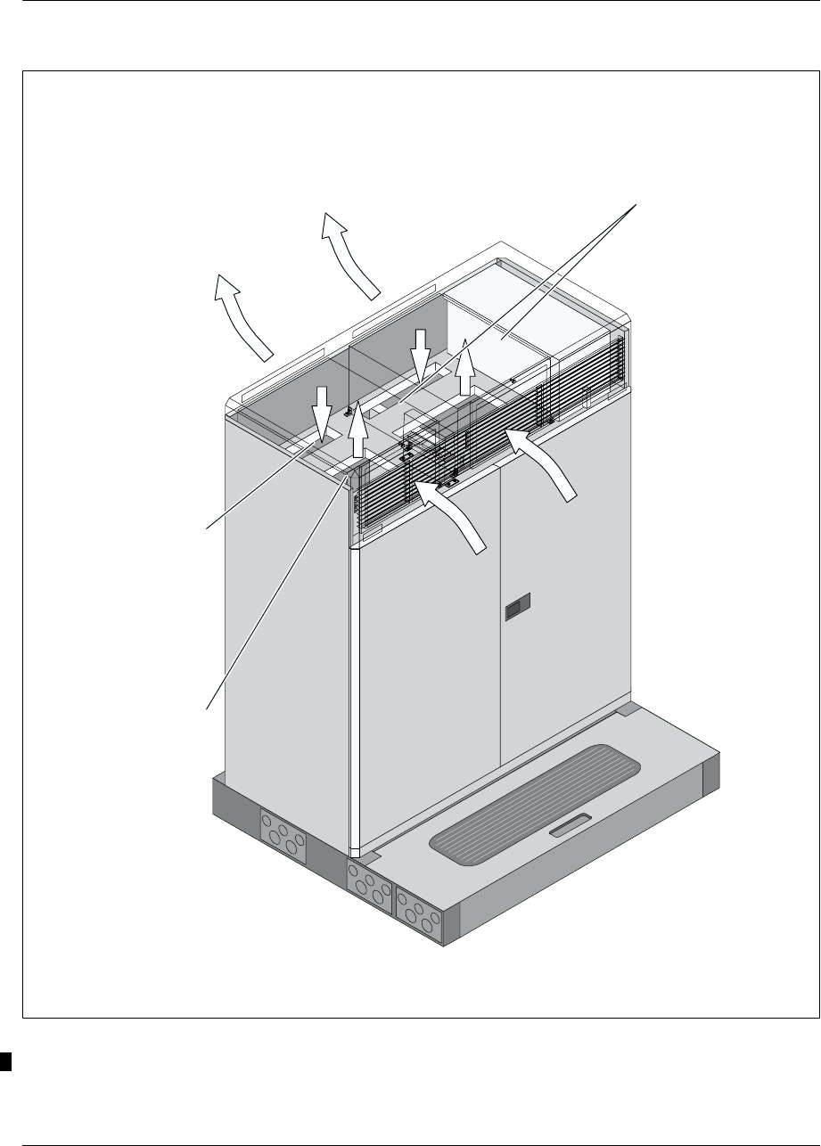
With ACUs
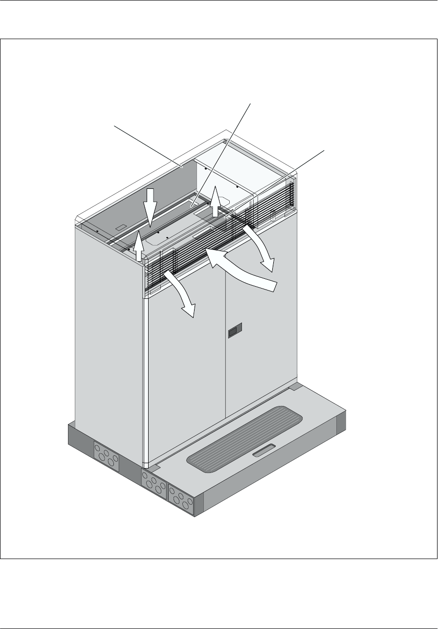
Figure 1–1 shows the S8000 Outdoor with an ACU climatic system.
The top and main compartments communicate through main compartment air inlets
and main compartment outlets (see Figure 1–2). The top compartment has
openings on the cabinet front panel that allow air to enter the cooling units and
openings on the rear of the cabinet that allow the cooling units to fan air out of the
cabinet.
Each ACU includes a compressor (ac–powered), an evaporator, condenser coils and
refrigerant lines, external and internal air blowers, 1000W heater (resistance plate
heater), digital controller, internal and ambient air temperature sensors, air filters,
EMI filters, ac/dc rectifier/alarm board and circuit breakers.
The internal temperature sensors are used to regulate the temperature inside the
cabinet. They are located on the climatic units, at the opening enabling air to pass
from the main compartment to the top compartment. The ambient air temperature
sensors enable the PCU to cut its dc power supply when the thresholds are exceeded.
These sensors are located above the BCF or CBCF compartment or below the
rectifiers.
The external air blower is to circulate the outside air across a condenser to extract
heat from the refrigerant and expel heat to the outside air. The internal air blower
circulates air through the BTS and over an evaporator to collect heat from the
electronics.
There are six LEDs on the front side of each cooling unit. These LEDs indicate the
alarms detected on the following type of failure (see Figure 1–3):
CTRL (orange): The controller display is alarmed.
FAN (orange): The fans for ambient air and internal equipment air are alarmed.
Each airflow path contains sensors to measure the air blower speed for an air
mover failure.
HP (orange): The pressure inside the compressor is controlled to sense a high or
low pressure for a compressor failure.
CS (green) : At cold start the LED comes on if the ACUs are well ac–powered.
dc (green) : The dc breaker is alarmed.
ac (green) : The ac breaker is alarmed.
These LEDs are lit when healthy and off on alarm.

Cabinet descriptionNortel Networks Confidential 1–3
S8000/S8002/S8006 BTS Reference Manual
Internal batteries (optional)
Top compartment
Main
compartment
Climatic system
(2 ACUs)
Air inlet
Air outlets
Alarm LEDs
Controller display
Figure 1–1 S8000 Outdoor BTS with ACU climatic system
Cabinet description Nortel Networks Confidential
1–4
PE/DCL/DD/0063
411–9001–063 Standard 12.07/EN September 2000 GSM/BSS V12
Climatic unit air outlets
Climatic units
Top
compartment
air inlets
Top
compartment
air outlets
BTS front panel
Figure 1–2 S8000 Outdoor BTS: Air circulation in the BTS with ACUs
Cabinet descriptionNortel Networks Confidential 1–5
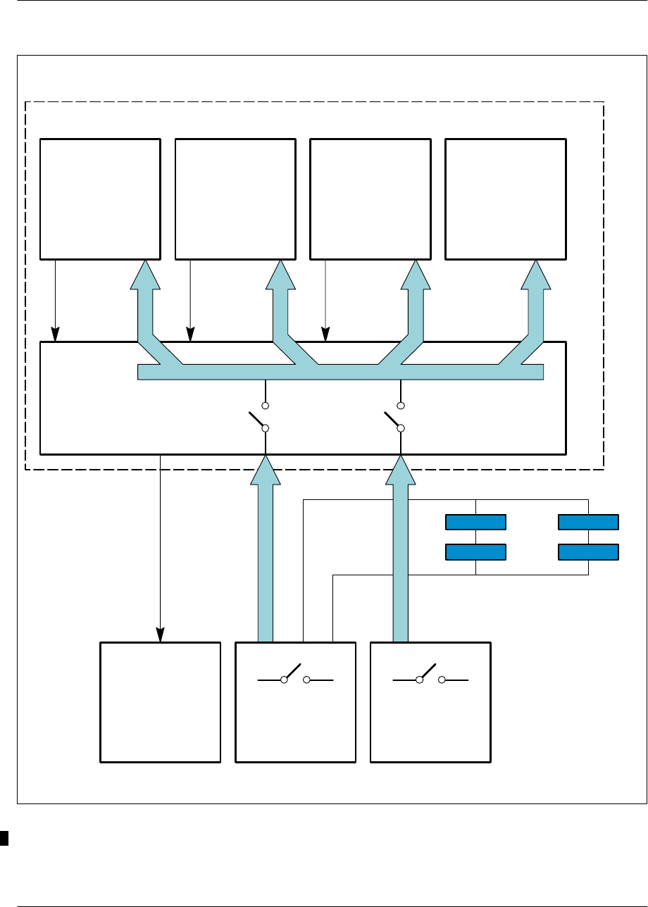
S8000/S8002/S8006 BTS Reference Manual
Cooling
system Evaporation
ventilation Condensation
ventilation Heating
system
Alarm
ac mains
Alarm
48V dc
Climatic unit
ALCO
or
RECAL
dc circuit
breaker
PCU ac box
ac circuit
breaker
dc circuit
breaker with
alarm
ac circuit
breaker with
alarm
Climatic unit
controller
Alarm
High temperature
thermostats Low temperature
thermostats
48V dc
Alarm
ac mains
Figure 1–3 S8000 Outdoor BTS: ACU climatic system diagram

Cabinet description Nortel Networks Confidential
1–6
PE/DCL/DD/0063
411–9001–063 Standard 12.07/EN September 2000 GSM/BSS V12
On each cooling unit there is also a controller display (red 7–segment display) that
indicates the internal air temperature. This controller display has two LEDs :
COOL/DELAY (red): lit when the internal air temperature reaches 40°C
(104°F).
HEAT (red): lit when the heater is on.
Technical characteristics
The ventilated air flow rate is 400 m3/hour (14.125 cubic feet/hour).
The maximum temperature of output air is +70°C (158°F).
With DACS
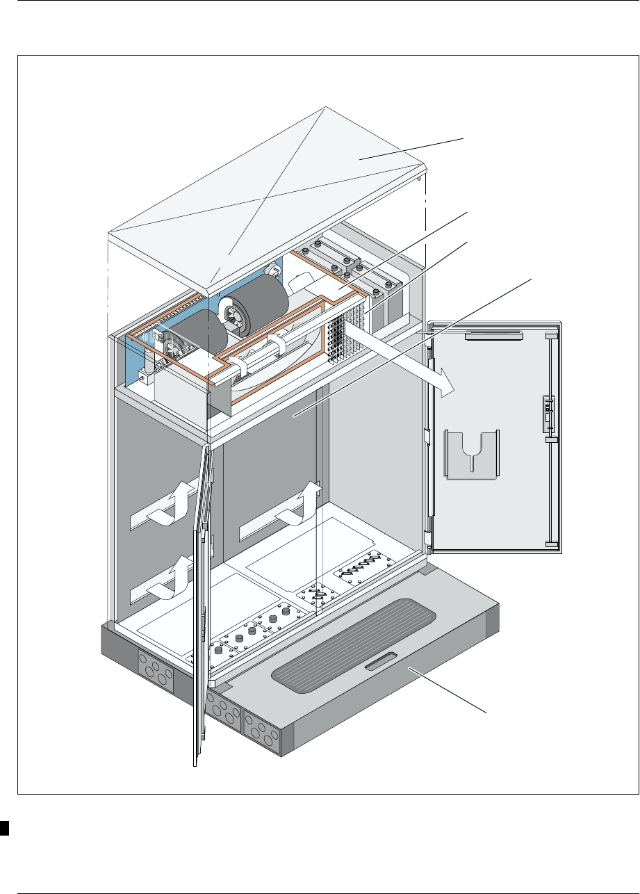
Figure 1–4 shows the S8000 Outdoor with an DACS climatic system.
The operating principle is the following:
The air damper opens to admit external air (incoming air being filtered) and
controls the inner cabinet environment by mixing appropriate amounts of outside
and recirculated air.
The twin blowers drive air down the rear duct and into the equipment enclosure
via slots at the rear. Returned air to the cooling system is routed through two sets
of holes in the base, with excess air being rejected from vents either located on
either side of the system (see Figure 1–5).
The internal temperature control is achieved by a high quality thermistor having an
accuracy of ±0.2°C (32,36_F) between 0°C (32_F) and 70°C (158_F).This device
is located in the left hand exit duct above a hole on the duct side ; this hole ensures
that the thermistor is constantly in a moving air stream, regardless of damper
position. Cooling system operational mode is solely dictated by the information
provided by the thermistor.
There are four operational modes:
Low temperature –40°C (–40°F) <Tcab <15°C (59°F)
The heater is energised, the damper closed to the outside and air is recirculated
via the holes in the base of the cooling system.
Medium temperature 15°C (59°C) <Tcab <40°C (104°F)
The heater is switch off, the damper remains closed and further heating of the
equipment enclosure is achieved solely by the internal equipment loading.
Cabinet descriptionNortel Networks Confidential 1–7
S8000/S8002/S8006 BTS Reference Manual
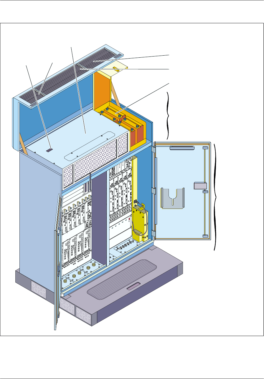
Internal batteries (optional)
Top compartment
Main
compartment
Climatic system
(DACS)
Air inlet
Window for
alarm LEDs Air outlet
Air
outlets
Figure 1–4 S8000 Outdoor BTS with DACS climatic system
Cabinet description Nortel Networks Confidential
1–8
PE/DCL/DD/0063
411–9001–063 Standard 12.07/EN September 2000 GSM/BSS V12
Climatic unit
air outlets
Climatic unit
Bottom compartment
air inlets
Top compartment
air outlet
BTS front panel
Climatic unit
air inlet
Figure 1–5 S8000 Outdoor BTS: Air circulation in the BTS with DACS or “LN” DACS

Cabinet descriptionNortel Networks Confidential 1–9
S8000/S8002/S8006 BTS Reference Manual
Normal temperature Tcab = 40°C (104°F)
The damper position is controlled automatically by the modulating motor,
mixing appropriate amounts of recirculated and external air to maintain a
constant temperature. Excess air is rejected from the cooling system from vents
either side of the cooling system.
High temperature Tcab > 40°C (104°F)
Although the damper is fully open, the cooling system is unable to keep the
cabinet temperature to 40°C (104°F) which now rises in sympathy with the
external temperature. At an outside temperature of 50°C (122°F), the internal
cabinet will rise to a nominal 60°C (140°F) under fully loaded conditions.
The cooling system is supplied:
with two hard alarm outputs:
•The first alarm output signals a fault on the cooling system,
•The second one indicates a maintenance requirement for the filter.
three alarm LEDs for on–site fault diagnostics:
•The red LED indicates critical alarm for fan failure.
•The yellow LED indicates critical alarm for heater circuit failure.
•The green LED indicates maintenance alarm for clogged filter.
On the top of the cooling system, there is a window in the lid which allows to
view the LEDs (see Figure 1–4). They are normally on when healthy and off on
alarm.
The cooling system is DC powered that allows internal or external battery back–up.
The dc power consumption of the cooling system is 400–450W. The cold start–up
performance of the unit is controlled by an inbuilt ac to dc converter (for operation
of the fans) and by a 2.5 kW heating element.
With “LN” (Loise Noise) DACS
Figure 1–6 shows the S8000 Outdoor with an ”LN” DACS climatic system.
The operating principle is the following:
The air damper opens to admit external air (incoming air being filtered) and
controls the inner cabinet environment by mixing appropriate amounts of outside
and recirculated air.
The twin blowers drive air down the rear duct and into the equipment enclosure
via slots at the rear. Returned air to the cooling system is routed through two sets
of holes in the base, with excess air being rejected from vents either located on
either side of the system (see Figure 1–5).
Cabinet description Nortel Networks Confidential
1–10
PE/DCL/DD/0063
411–9001–063 Standard 12.07/EN September 2000 GSM/BSS V12
Cubicle
Outlet vent
DACS unit
Hood
Plinth (optional)
Figure 1–6 S8000 Outdoor BTS with “LN” DACS climatic system

Cabinet descriptionNortel Networks Confidential 1–11
S8000/S8002/S8006 BTS Reference Manual
With “LN” DACS two operating modes of the twin blowers are available:
full speed mode
control speed mode. In this mode:
•if the temperature is > 45°C (113°F), the blowers run at full speed (2500 rpm).
•if the temperature is ≤ 45°C (113°F), the blowers run at slow speed
(1800 rpm).
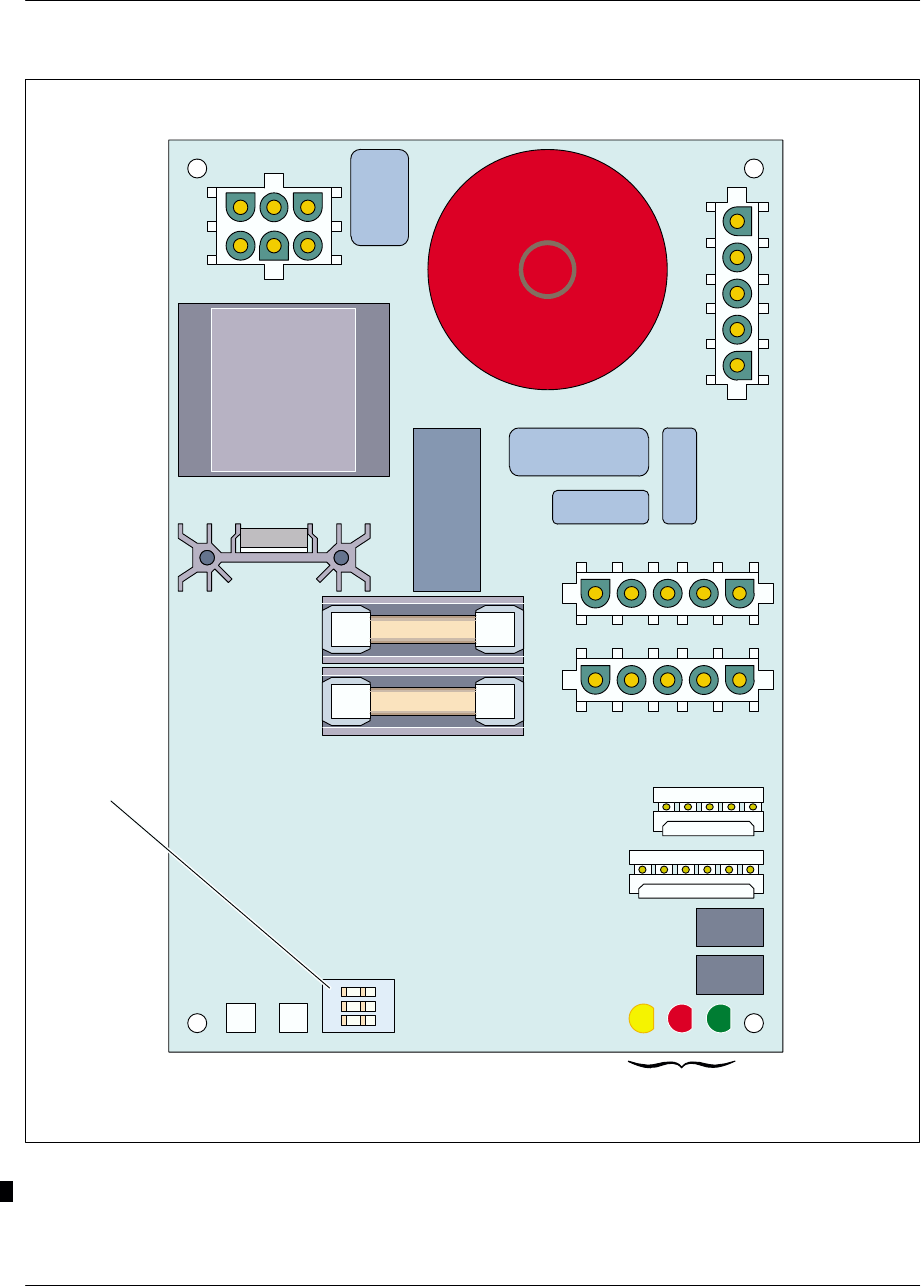
The full speed mode or control speed mode is selected by switches located on the
control board (see Figure 1–7).
The temperature control is achieved by two high quality thermistor having an
accuracy of ±0.2°C (32,36_F) between 0°C (32_F) and 70°C (158_F):
One is located in the left hand exit duct above a hole on the duct side. This hole
ensures that the thermistor is constantly in a moving air stream, regardless of
damper position.
The other one is located behind the air inlet, and measures the ambiant air
temperature.
Cooling system operational mode is solely dictated by the information provided by
the thermistor.
The nominal internal operating temperature (Ts) is set by switches (see Table 1–1)
located on the control board (see Figure 1–7).
The factory presetting temperature is 35°C (95_F).
Choice of nominal internal operating
temperature (Ts) Blower speed
control Nominal
internal
operating
Switch (SW1/1) Switch (SW1/2) Switch (SW1/3)
operating
temperature
(Ts)
OFF ON ON
(for full speed) +35°C
(+ 95°F)
ON ON ON
(for full speed) +25°C
(+ 77°F)
Table 1–1 Setting of nominal internal temperature
Cooling system operational mode is solely dictated by the information provided by
the thermistor.
Cabinet description Nortel Networks Confidential
1–12
PE/DCL/DD/0063
411–9001–063 Standard 12.07/EN September 2000 GSM/BSS V12
SW1
LED1 LED2 LED3
OFF
123
Alarm LEDs
Figure 1–7 Control board of climatic system with “LN” DACS

Cabinet descriptionNortel Networks Confidential 1–13
S8000/S8002/S8006 BTS Reference Manual
There are four operational modes:
Low temperature –40°C (–40°F) <Tcab <15°C (59°F)
The heater is energised, the damper closed to the outside and air is recirculated
via the holes in the base of the cooling system.
Medium temperature 15°C (59°C) <Tcab < Ts
The heater is switched off, the damper remains closed and further heating of the
equipment enclosure is achieved solely by the internal equipment loading.
Normal temperature Tcab = Ts
The damper position is controlled automatically by the modulating motor,
mixing appropriate amounts of recirculated and external air to maintain a
constant temperature. Excess air is rejected from the cooling system from vents
either side of the cooling system.
High temperature Tcab > Ts
Although the damper is fully open, the cooling system is unable to keep the
cabinet temperature to Ts which now rises in sympathy with the external
temperature. At an outside temperature of 50°C (122°F), the internal cabinet will
rise to a nominal 60°C (140°F) under fully loaded conditions.
The cooling system is monitored by:
two hard alarm outputs:
•The first alarm output signals a fault on the cooling system,
•the second one indicates a maintenance requirement for the filter.
three alarm LEDs for on–site fault diagnostics.
•The red LED indicates critical alarm for fan failure.
•The yellow LED indicates critical alarm for heater circuit failure.
•The green LED indicates maintenance alarm for clogged filter.
On the top of the cooling system, there is a window in the lid which allows to
view the LEDs (see Figure 1–4). They are normally on when healthy and off on
alarm.
The cooling system is DC powered that allows internal or external battery back–up.
The dc power consumption of the cooling system is 400–450W. The cold start–up
performance of the unit is controlled by an inbuilt ac to dc converter (for operation
of the fans) and by a 2.5 kW heating element.

Cabinet description Nortel Networks Confidential
1–14
PE/DCL/DD/0063
411–9001–063 Standard 12.07/EN September 2000 GSM/BSS V12
1.1.1.3 Plinth
The S8000 Outdoor BTS cabinet can be installed on a plinth (see Figure 1–8)
allowing for cable passage. The plinth characteristics are described in
document < 01 >, BSS Overview.
The plinth may contain the external alarm connection box, the PCM connection box
and the –48 V DC connection box.
These boxes are screwed into the inside of the plinth.
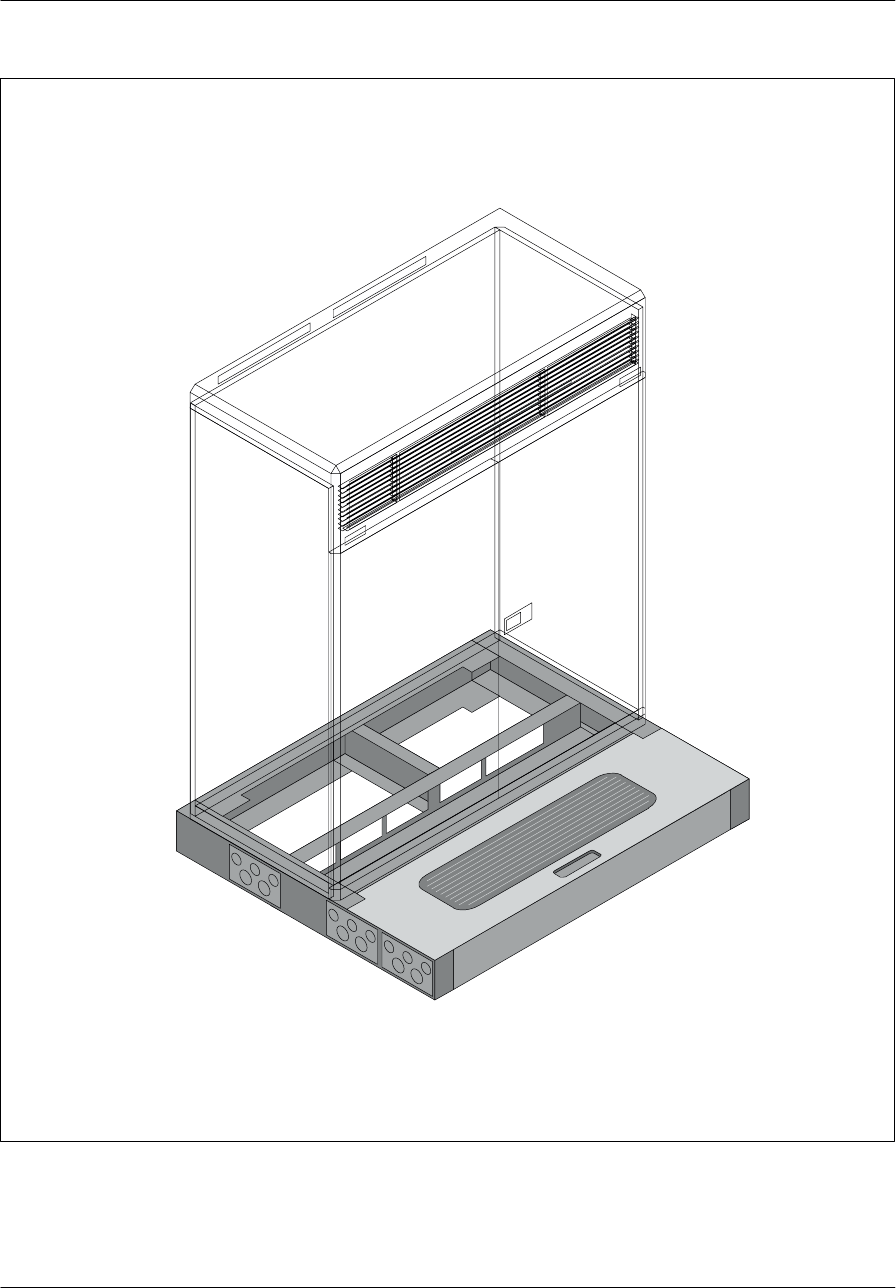
Cabinet descriptionNortel Networks Confidential 1–15
S8000/S8002/S8006 BTS Reference Manual
Note: One of the five–hole plates is replaced with a two–hole plate when there is an extension
cabinet.
Figure 1–8 S8000 Outdoor BTS: Plinth diagram

Cabinet description Nortel Networks Confidential
1–16
PE/DCL/DD/0063
411–9001–063 Standard 12.07/EN September 2000 GSM/BSS V12
1.1.2 S8000 Indoor BTS
1.1.2.1 Base cabinet
The S8000 Indoor BTS with BCF cabinet can be wall–mounted, or put on the floor.
The base cabinet is shown in Figure 1–9.
Physical characteristics
See document < 01 >, BSS Overview.
Operating temperature
When the base cabinet is turned on, the external ambient air temperature must be
between 0°C (32°F) and 45°C (113°F).
Once in operation, the base cabinet requires an external ambient air temperature
above –5°C (23°F) and below 45°C (113°F).
Power supply
See document < 01 >, BSS Overview.
Consumption
The maximum power consumption of the base cabinet is 2080W.
1.1.2.2 BCF cabinet
The BCF cabinet can be wall–mounted or put on a support device and must not be
placed further than 10 m (33’2’’) away from the base cabinet. The BCF cabinet is
shown in Figure 1–10.

Cabinet descriptionNortel Networks Confidential 1–17
S8000/S8002/S8006 BTS Reference Manual
DC connection
Filter
Ventilation grid
Radio output
ALPRO boards
Climatic unit
Figure 1–9 S8000 Indoor BTS: Base cabinet

Cabinet description Nortel Networks Confidential
1–18
PE/DCL/DD/0063
411–9001–063 Standard 12.07/EN September 2000 GSM/BSS V12
Figure 1–10 S8000 Indoor BTS: BCF cabinet

Cabinet descriptionNortel Networks Confidential 1–19
S8000/S8002/S8006 BTS Reference Manual
Physical characteristics
See document < 01 >, BSS Overview.
Operating temperature
When it is turned on, the BCF Cabinet requires an external ambient air temperature
between 0°C (32°F) and 45°C (113°F).
Once in operation, the BCF Cabinet requires an external ambient air temperature
above –5°C (23°F) and below 45°C (113°F).
Power supply
See document < 01 >, BSS Overview.
Consumption
The BCF cabinet maximum power consumption is 80 W.

Cabinet descriptionNortel Networks Confidential 1–29
S8000/S8002/S8006 BTS Reference Manual
1.2 Cabinet compartment layout
1.2.1 S8000 Outdoor BTS
The base cabinet and the extension cabinet are divided into three parts
(Figure 1–13 to Figure 1–15):
top compartment
left side
right side
The layout of the equipment in the base and extension cabinets is identical in the
top compartment and on the left side.
The cabinet layout on the right side of the base and extension cabinets is different.
In the base cabinet, the BCF or CBCF is located in the BCF or CBCF Compartment.
In the same compartment of the extension cabinet, a filling plate replaces the BCF
or CBCF.
1.2.1.1 Top compartment
The top compartment opens by means of a cover on the top of the cabinet. The front
of the cabinet is perforated to allow air to circulate. The top compartment has two
or three elements: the optional battery box and the climatic system (the DACS, or
two ACUs).
1.2.1.2 Compartment on the left side
User compartment
This compartment is available for Original Equipment Manufacturer (OEM). For
more information, refer to the documentation provided by the equipment
manufacturer.
For GSM 1800 frequency bands, Nortel has developed RW Series M products
whose reference to the document is the following: 840–900201–002. The user
interconnection compartment is optional. It is required only when a user kit or a
–48 V connection box is used.
PA interconnection compartment
The PA interconnection compartment centralizes the –48 V dc power supply of the
Power Amplifiers (PA).
Amplifier and alarm compartment
The amplifier and alarm compartment receives up to eight Power Amplifiers (PA)
and the Alarm Collecting unit (ALCO or RECAL). The ALCO or RECAL board
is connected to one or two external alarm protection boards (ALPRO), located
outside the cabinet.
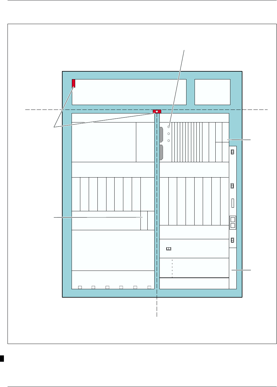
Cabinet description Nortel Networks Confidential
1–30
PE/DCL/DD/0063
411–9001–063 Standard 12.07/EN September 2000 GSM/BSS V12
P
AP
AP
AP
AP
AP
AP
AP
A
A
L
C
O
D
R
X
D
R
X
D
R
X
D
R
X
D
R
X
D
R
X
D
R
X
D
R
X
Climatic system Battery
compartment
User
compartment
PA interconnections
F–type
converters
Combiner interconnections
(COMICO)
ac box
DRX (*) interconnections
Power System
compartment
RF combiner and Tx-Filter
compartment (**)
P
C
M
I
5V/12A
5V/12A
5V/12A
PSCMD
P
C
M
I
P
C
M
I
G
T
W
G
T
W
C
S
W
M
C
S
W
M
D
S
C
D
S
C
D
S
C
D
S
C
S
Y
N
C
S
Y
N
C
BCF, ALCO and
USER fuses
User
intercon-
nections
(*) (*) (*) (*) (*) (*) (*) (*)
Left side Right side
RX-splitters
Top
compartment
BCF
Door switch
Note: (*) DRX or e–DRX.
(**) The Tx-Filter module is optional.
Figure 1–13 S8000 Outdoor BTS: Base cabinet layout (with BCF)
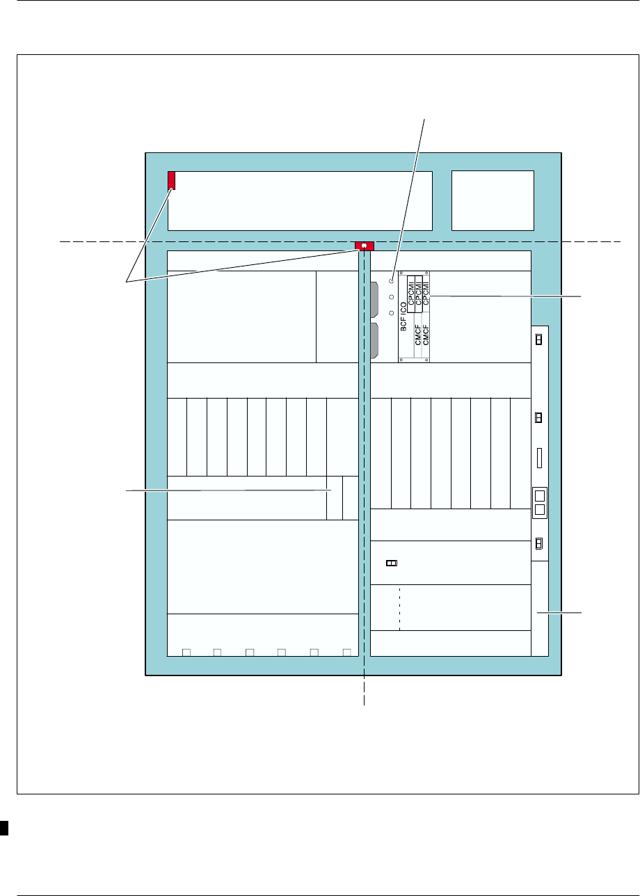
Cabinet descriptionNortel Networks Confidential 1–31
S8000/S8002/S8006 BTS Reference Manual
P
AP
AP
AP
AP
AP
AP
AP
A
R
E
C
A
L
Climatic system Battery
compartment
User
compartment
PA interconnections
F–type
converters
Combiner interconnections
(COMICO)
ac box
DRX (*) interconnections
Power System
compartment
RF combiner and Tx-Filter
compartment (**)
CBCF
CBCF, RECAL and
USER fuses
User
intercon-
nections
Left side Right side
RX-splitters
D
R
X
D
R
X
D
R
X
D
R
X
D
R
X
Filling plate
D
R
X
Top
compartment
Door switch
D
R
X
D
R
X
(*) (*) (*) (*) (*) (*) (*) (*)
Note: (*) DRX or e–DRX.
(**) The Tx-Filter module is optional.
Figure 1–14 S8000 Outdoor BTS: Base cabinet layout (with CBCF)
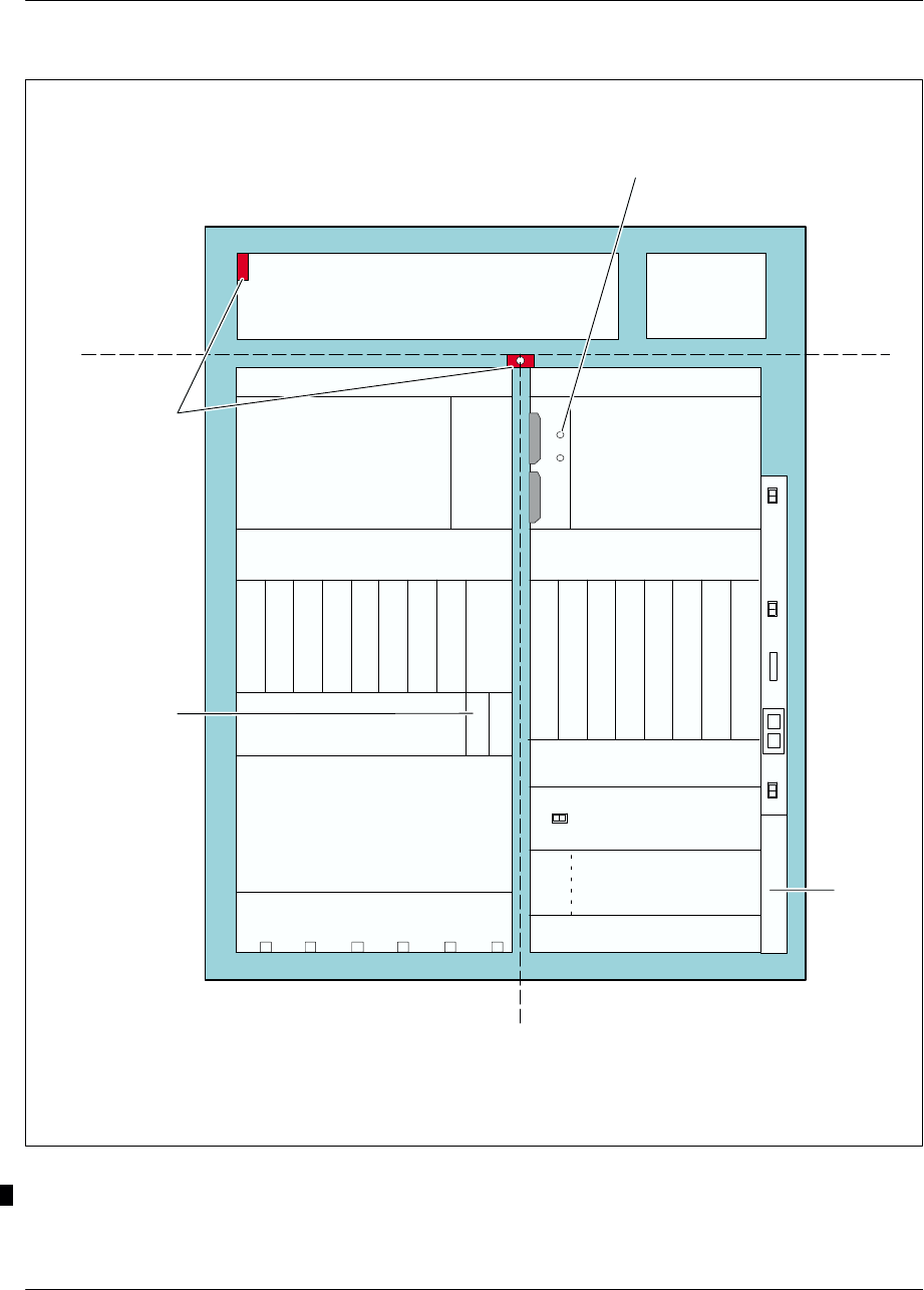
Cabinet description Nortel Networks Confidential
1–32
PE/DCL/DD/0063
411–9001–063 Standard 12.07/EN September 2000 GSM/BSS V12
Climatic system Battery
compartment
User
compartment
PA interconnections
P
AP
AP
AP
A
F–type
converters
Combiner interconnections
(COMICO)
ac box
P
AP
AP
AP
A
R
E
C
A
L
(***)
DRX (*) interconnections
Power System
compartment
RF combiner and Tx-Filter
compartment (**)
Filling plate
RECAL and USER fuses
User
intercon-
nections
Left side Right side
RX–splitters
Top
compartment
Door switch
(***) When the BCF is used:
S the ALCO board replaces the RECAL board
S the ALCO fuse replaces the RECAL fuse.
D
R
X
D
R
X
D
R
X
D
R
X
D
R
X
D
R
X
D
R
X
D
R
X
(*) (*) (*) (*) (*) (*) (*) (*)
Note: (*) DRX or e–DRX.
(**) The Tx-Filter module is optional.
Figure 1–15 S8000 Outdoor BTS: Extension cabinet layout

Cabinet descriptionNortel Networks Confidential 1–33
S8000/S8002/S8006 BTS Reference Manual
F–type converter
A converter, called F–type converter, supplies ± 15 V dc to the LNA–splitter and
the VSWR–meter.
A second F–type converter is available as an option.
RF Combiner and Tx–Filter compartment
The RF Combiner and Tx–Filter compartment can hold a maximum of either of the
following combination of modules:
six RF Combiner modules, duplexer–only (D)
six RF Combiner modules, two–way hybrid duplexer (H2D)
three RF Combiner modules, four–way hybrid duplexer (H4D)
four RF Combiner modules, duplexer–only (D) and four Tx–Filter modules
(TxF)
The D, H2D, and H4D RF Combiner modules perform the following functions:
transmission coupling of two, three, or four channels
filtering and duplexing of transmission and reception signals on the same
antenna port
amplification of reception signals
monitoring of the antenna VSWR (option)
The Tx–Filter performs the following functions:
filtering of transmission signals
monitoring of the antenna VSWR (option)
Combiner interconnection compartment (COMICO)
The COMICO is the interconnection board for the modules of the RF Combiner
compartment that centralizes inputs/outputs on the alarms and the power supplies.
1.2.1.3 Compartment on the right side
BCF or CBCF Compartment
The BCF or CBCF Compartment of the base cabinet contains a fuse panel and a BCF
unit or CBCF Module.
The following BCF boards are visible and accessible in the front panel of the BCF
Compartment:
three PCM Interface boards (PCMI)
two Gateway boards (GTW)
two Control, Switching and Management boards (CSWM)

Cabinet description Nortel Networks Confidential
1–34
PE/DCL/DD/0063
411–9001–063 Standard 12.07/EN September 2000 GSM/BSS V12
four Data Signaling Concentration boards (DSC)
two synchronization boards (SYNC)
three 48 V / ±5 V / 12A converters (one converter is optional)
one Power Sypply Command board (PSCMD)
Two CBCF boards are visible on the front panel of the CBCF module:
Compact Main Common Function (CMCF)
Compact PCMI (CPMI)
The fuse panel in the base cabinet contains three fuses:
4A–fuse to protect the BCF unit or CBCF Module
1A–fuse to protect the alarm collecting board (ALCO or RECAL)
10A–fuse to protect the user compartment
Since there is no BCF or CBCF in the extension cabinet, a filling plate occupies the
place of these units.
The fuse panel in the extension cabinet contains only two fuses: a 1A fuse for the
alarm collecting board and a 10A–fuse for the user compartment.
DRX (or e–DRX) interconnection compartment
The interconnection compartment centralizes DRX (or e–DRX) outputs. It connects
the modules to the Power Amplifiers (PA) on the one hand, and interconnects them
by means of the FH bus, on the other.
DRX (or e–DRX) compartment
The compartment receives up to eight modules.
RX–splitter compartment
The RX–splitter compartment receives up to six RX–splitters, which receive RF
signals from the LNA splitter and distribute them to the DRXs (or e–DRXs) RX
inputs.
Power system compartment
The power system compartment may be configured according to two types:
The first type is a Power Controller Unit (PCU) and up to six 600W rectifiers
(one of them redundant) which convert Mains Voltage to –48 V dc to be used in
the cabinet. According to the number of DRXs (or e–DRXs) per cell, the number
of rectifiers may be decreased.
The other type is an integrated power system including a Controller Module, a
Distribution Module and up to seven 500W rectifiers (one of them redundant).

Cabinet descriptionNortel Networks Confidential 1–35
S8000/S8002/S8006 BTS Reference Manual
ac box
This box is located on the right–hand side of the right–hand part of the cabinet. It
receives the mains voltage and distributes it to the power system compartment and
to the cooling system. The PCU only controls the dc supply. ac supply connects to
the back panel that is common for all rectifiers.
In the extension cabinet, a filling plate replaces the BCF. On left of this filling plate
there are two fuses.
1.2.2 S8000 Indoor BTS
1.2.2.1 Base cabinet
The compartment layout of the base cabinet is presented in Figure 1–16.
Cabinet top
The cabinet top (see Figure 1–25) can hold a maximum of two ALPRO modules.
An ALPRO module consists of an ALPRO board, a protection cover, and an
interconnection plate.
The fan grid in the upper panel is an air outlet. Radio outputs, the cabling with the
separate BCF Cabinet (if applicable) and the cabinet power supply are achieved
from the top of the cabinet.
Combiner interconnection (COMICO) compartment
This compartment consists of an interconnection board for the combiner
compartment modules, which centralizes inputs/outputs on the alarms and the
power supplies.
RF combiner and Tx–Filter compartment
The RF Combiner and Tx–Filter compartment can hold a maximum of either of the
following combination of modules:
six RF Combiner modules of the duplexer only type (D)
six RF Combiner modules of the two–way hybrid duplexer type (H2D)
three RF Combiner modules of the the four–way hybrid duplexer type (H4D)
four RF Combiner modules of the duplexer only type (D) and four Tx–Filter
modules (TxF)
one RF Combiner Module of eight–way cavity combiner and two duplexers
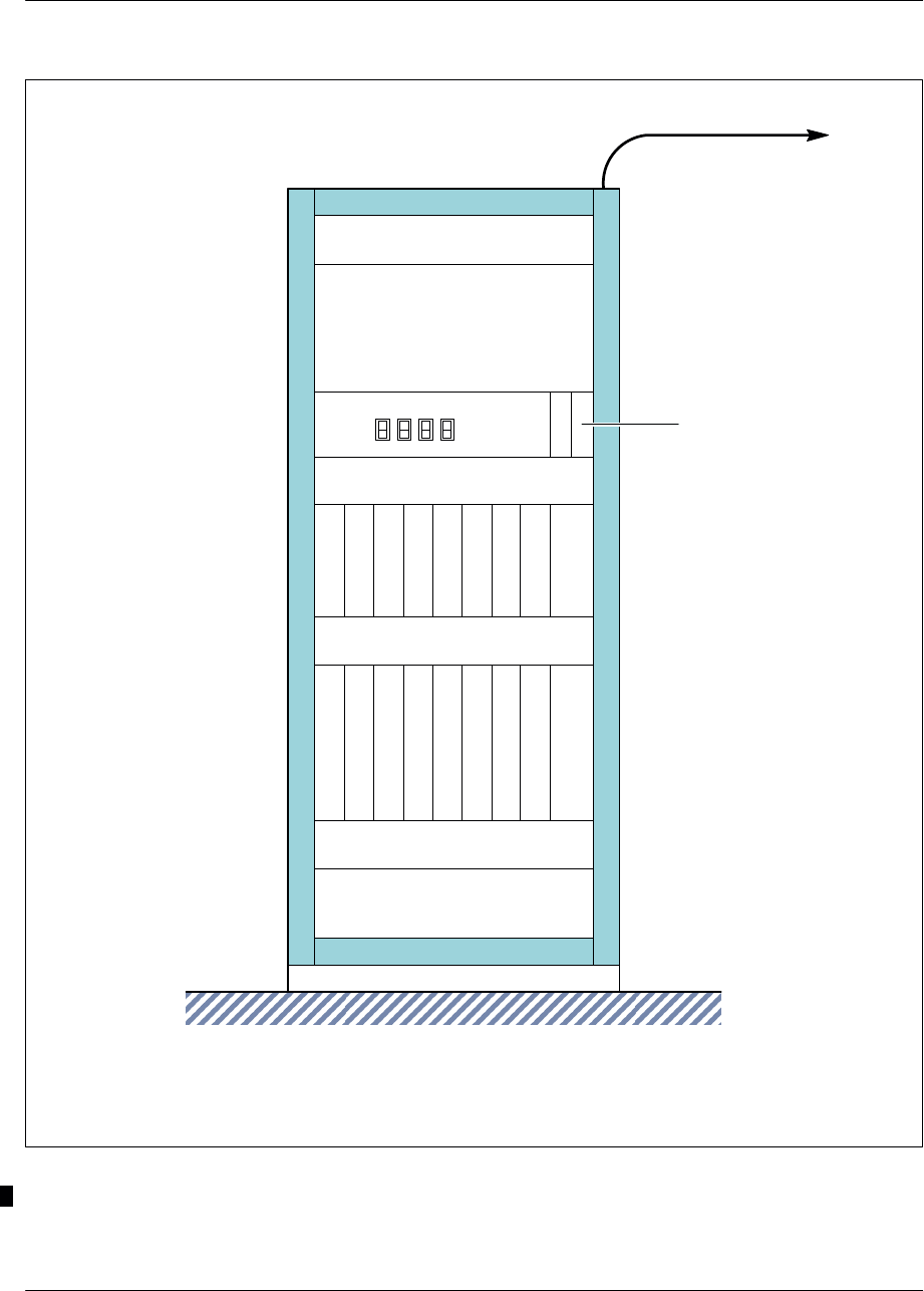
Cabinet description Nortel Networks Confidential
1–36
PE/DCL/DD/0063
411–9001–063 Standard 12.07/EN September 2000 GSM/BSS V12
P
A
DRX interconnections (*)
RF combiner and Tx–Filter
compartment (**)
Combiner interconnections
(COMICO)
F–type
converters
PA interconnections
R
E
C
A
L
(***)
P
AP
AP
AP
AP
AP
AP
A
D
R
X
D
R
X
D
R
X
dc compartment
D
R
X
D
R
X
D
R
X
D
R
X
D
R
X
C
B
C
F
(***)
(*) (*) (*) (*) (*) (*) (*) (*)
RX–splitters
To BCF cabinet (if applicable***)
Ventilation system
(***) When the BCF cabinet is used:
•the ALCO board replaces the RECAL board
• a filling plate replaces the CBCF module.
Note: (*) DRX or e–DRX.
(**) The Tx-Filter module is optional.
Figure 1–16 S8000 Indoor BTS: Base cabinet layout

Cabinet descriptionNortel Networks Confidential 1–37
S8000/S8002/S8006 BTS Reference Manual
The RF Combiner modules perform the following functions:
transmission coupling of the channels
filtering and duplexing of transmission and reception signals on the same
antenna port
amplification of reception signals
monitoring of the antenna VSWR (option)
The Tx–Filter performs the following functions:
filtering of transmission signals
monitoring of the antenna VSWR (option)
dc compartment
This compartment contains four switches to disconnect the power supply to the
Power Amplifiers, the fans, the ALCO or RECAL board and the BCF or the CBCF.
The compartment also contains an F–type converter, which supplies ± 15 V dc to
the LNA–splitter and the VSWR–meter. A second F–type converter is available as
an option.
PA interconnection compartment
This compartment centralizes the –48 V dc power supply of the Power Amplifiers
(PA).
Power Amplifier and alarm compartment
This compartment contains:
one to eight power amplifiers (PAs)
one ALCO or RECAL board
It is possible to connect the ALCO or RECAL board to one or two external alarm
protection boards (ALPRO) located on top of the base cabinet.
DRX (or e–DRX) interconnection compartment
This compartment centralizes DRX (or e–DRX) outputs. It connects them to the
Power Amplifiers (PA) on the one hand , and interconnects them by means of the
FH bus, on the other.
DRX (or e–DRX) and CBCF Compartment
This compartment contains a maximum of eight modules.
The CBCF module is located in the far right of this compartment. A filling plate
replaces the CBCF when the BCF is used.
RX–splitter compartment
This compartment contains up to six RX–splitters, which receive data signals from
the units in the coupler compartment and distributes them to the DRXs (or
e–DRXs).

Cabinet description Nortel Networks Confidential
1–38
PE/DCL/DD/0063
411–9001–063 Standard 12.07/EN September 2000 GSM/BSS V12
Climatic compartment
This compartment contains three fans, and the FANICO board (FANICO PCB–
Printed Circuit Board). One fan is optional and is used to ensure redundancy. This
board enables the control of the rotation of each fan and sends an alarm (one for each
fan) to the ALCO or RECAL board when the fan speed goes below a fixed threshold.
1.2.2.2 BCF cabinet
The layout of the BCF cabinet is presented in Figure 1–17 and Figure 1–18.
Upper compartment
This compartment contains three fans and a FANICO board (identical to the one in
the radio cabinet). Rotation management alarms are sent to the ALCO board.
There are three 800mA–fuses on the front panel of the BCF to protect the fans.
Lower compartment
This compartment contains the following BCF boards:
three PCMI boards
two gateway boards (GTW)
two control and switching units (CSWM)
four data signaling concentration units (DSC)
two synchronization modules (SYNC)
three 48 V / ± 5 V / 12 A converters (one converter is optional)
one Power Supply CoMmanD unit (PSCMD).
There is a 4A–fuse on the front panel to the left of the BCF board to protect itself.

Cabinet descriptionNortel Networks Confidential 1–39
S8000/S8002/S8006 BTS Reference Manual
FANICO Printed
Circuit Board
To base cabinet
Fuse
(F800mA, H250V) Fans
PSCMD
5V/12A 5V/12A
5V/12A
F01
4A
BCF
PCMI
PCMI
PCMI
GTW
GTW
CSWM
CSWM
DSC
DSC
DSC
DSC
SYNC
SYNC
Upper
compartment
Lower
compartment
Figure 1–17 S8000 Indoor BTS: BCF cabinet layout
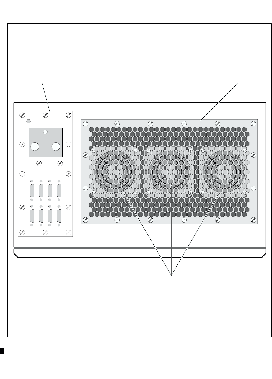
Cabinet description Nortel Networks Confidential
1–40
PE/DCL/DD/0063
411–9001–063 Standard 12.07/EN September 2000 GSM/BSS V12
GND
–48V 0V
O
&
M
0
/
1
O
&
M
2
/
3
O
&
M
4
/
5
P
C
M
0
/
1
B
C
F-
A
L
A
R
M
A
B
I
S
P
C
M
4
/
5
P
C
M
2
/
3
GND
GND
–48V 0V
Rear
Front
Connectors Ventilation grid
Fans
Figure 1–18 S8000 Indoor BTS: BCF cabinet top view

Cabinet descriptionNortel Networks Confidential 1–41
S8000/S8002/S8006 BTS Reference Manual
Back panel
The BCF back panel connects the switching part of the BTS. It provides connections
for the BCF boards (see Figure 1–19). It receives the external PCMs from the BSC
(A–bis interface) and the six private PCMs from the BTS. It also distributes the
O&M bus, its own alarms and the 48 V power supply of the ALCO board.
The BCF back panel has the following connectors:
A 37–pin female connector receives the six PCMs of the A–bis interface.
Three 25–pin female connectors distribute the O&M bus.
Three 25–pin female connectors each distribute two private PCMs.
A 3–pin connector is used for power supply.
A 4–pin connector distributes converter alarms to the ALCO unit.
Thirty 96–pin male connectors connect the P1 and P2 connectors of the
following units: PCMI, DSC, PSU, CSWM, GTW, and SYNC.
Thirteen 8–pin male connectors supply the units connected to the back–panel.
The BCF back panel also connects PCM termination resistors in order to reduce
radioelectric transmission and prevent end–of–line multiple reflection problems.
The P2 connectors are equipped with a localizing device that prevents the insertion
of a board into the wrong slot. This is done by means of cells on the back–panel that
are blocked and tabs that are cut out on the board connectors (see Figure 1–20).
The BCF back panel has only one ground. No distinction is made between logical
ground and physical ground. For units that use this distinction, the mechanical
ground is connected to the logical ground.
However, the reference 0 V of the –48 V power supply (M0 V) is not connected to
the back–panel ground.
The –48 V dc power is protected by fuses.
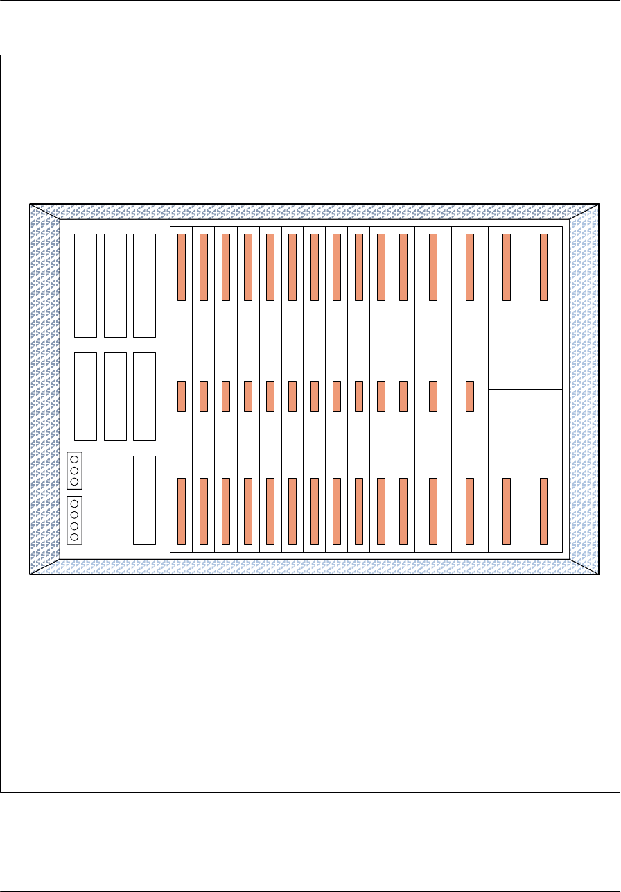
Cabinet description Nortel Networks Confidential
1–42
PE/DCL/DD/0063
411–9001–063 Standard 12.07/EN September 2000 GSM/BSS V12
P
C
M
I
0
P
C
M
I
1
P
C
M
I
2
G
T
W
A
G
T
W
B
C
S
W
M
A
C
S
W
M
B
D
S
C
1
D
S
C
2
D
S
C
3
D
S
C
0
S
Y
N
C
A
S
Y
N
C
B
P
S
U
0
P
S
U
1
P
S
U
2
P
S
C
M
D
O
M
B
o
u
t
2
O
M
B
o
u
t
1
O
M
B
o
u
t
0
P
C
M
P
2
P
C
M
P
1
P
C
M
P
0
A
B
I
S
48 V(–)
GNDM
48 V(+)
ALARM
Key : OMBoutX: O&M output connector No. X
PCMPX: Private PCM connector No. X
Figure 1–19 BCF back panel

Cabinet descriptionNortel Networks Confidential 1–43
S8000/S8002/S8006 BTS Reference Manual
P2 P2 P2 P2 P2
1
3
7
PCMI DSC CSWM GTW SYNC
5
6
Figure 1–20 Localizing device

Cabinet description Nortel Networks Confidential
1–136
PE/DCL/DD/0063
411–9001–063 Standard 12.07/EN September 2000 GSM/BSS V12
1.4 Power supply
1.4.1 S8000 Outdoor
The power system supplies 48 V dc power to the units in the cabinet from the mains
power supply.
1.4.1.1 Description
The power system can have the following configurations:
for the S8000 Outdoor BTS:
•an ac box, a Power Controller Unit (PCU), a set of 600W rectifier units (SRU)
and a set of batteries
•an ac box, a Controller Module, a set of 500W Rectifiers, a Distribution
Module and a set of batteries
The controller module and distribution module make up the PCU.
The PCU connects the rectifiers to the cabinet units and to the batteries (only for
S8000 Outdoor BTS).
In this section, the SRU refers to both types of rectifier sets.
The PCU can be connected to a set of several rectifiers whose outputs are connected
in parallel:
for S8000 Outdoor BTS:
•either a set of two to six 600W rectifiers (one for redundancy)
•or a set of two to seven 500W rectifiers (one for redundancy)
Only for the S8000 Outdoor BTS, the PCU is connected to the batteries located
either inside or outside the cabinet. It has four separate outputs (outputs 1 to 4) that
supply the cabinet utilizations.
There are two types of battery units:
internal batteries mounted on the top of the cabinet, which consist of four
12 V dc batteries in series (one string)
external batteries located in the external battery cabinet, and configured in a
maximum of four strings. Each string consists of four 12V dc batteries in series;
the four strings being connected in parallel.

Cabinet descriptionNortel Networks Confidential 1–137
S8000/S8002/S8006 BTS Reference Manual
PCU functions
Two types of PCUs are available, depending on the converter type. These two PCU
types have the same functions but are tied to their own rectifiers.
The PCU has the following functions:
It connects the SRU to the batteries (only for the S8000 Outdoor BTS). When the
rectifiers are no longer running, the batteries can supply the PCU outputs
according to the option chosen, the choice being by front panel wiring:
•option 1: two of the four PCU outputs are supplied
•option 2: the four PCU outputs are powered (this is mandatory in the case of
external batteries
It generates four 54 V dc outputs (outputs 1 to 4) for supply of the cabinet boards.
It receives the alarms from the rectifiers.
It receives an analog signal from the temperature probe located on the batteries
(internal or external) and sends a signal to the SRU to adjust rectifier output
voltage inversely to battery temperature (floating voltage).
It generates a disconnection of its four load outputs depending on the signal
received from two ambient temperature probes (one is located at the top of the
cabinet, the other at the bottom).
PCU connections with the SRU
The SRUs, connected in parallel, are connected to the PCU by means of the
following inputs/outputs:
54 V (+) and 54 V(–)
dc fault (alarm)
ac fault (alarm)
overtemperature (alarm)
missing module (alarm)
floating voltage control
remote control
load share
PCU connections with the batteries (only for the S8000 Outdoor BTS)
The batteries are connected to the PCU by means of the following inputs/outputs:
54 V (–) internal batteries
54 V (–) external batteries
54 V (+) internal and external batteries
(+) and (–) of the temperature probe of the internal batteries
(+) and (–) of the temperature probe of the external batteries

Cabinet description Nortel Networks Confidential
1–138
PE/DCL/DD/0063
411–9001–063 Standard 12.07/EN September 2000 GSM/BSS V12
Interface between the PCU and the ALCO or RECAL board
The following signals are the interface between the PCU and the ALCO or RECAL
board:
Load1 threshold (PCU internal alarm, also sent to ALCO or RECAL)
PCU protective devices (PCU internal alarm, also sent to ALCO or RECAL)
battery on discharge (alarm) available only for the S8000 Outdoor BTS
dc fault (alarm)
ac fault (alarm)
overtemperature (alarm).
The following signal carries out the control:
CEATS 1 (Cabinet Extreme Ambient Temperature Signal).
The following cables are not connected:
Load2 threshold (PCU internal alarm, also sent to ALCO or RECAL)
missing module (alarm)
remote control (used to cut the 48 V dc and switch to batteries)
common alarms.
Battery operation of boards in the cabinet (only for the S8000 Outdoor BTS)
The PCU enables the cabinet to run on either internal or external batteries
(connection of the internal or external batteries is carried out manually, and it is not
possible to connect both types simultaneously). Two operating options are possible.
option 1:
•When the internal or external batteries are connected to the system, the SRU
powers all the outputs and, if necessary, supplies power to the batteries
(charging phase).
•If the SRU is not supplying any power, the internal or external batteries
energize output 4 (BCF, user equipment and ALCO or RECAL board).
option 2:
•When the external batteries are connected (in which case the internal batteries
are disconnected manually), the SRU energizes all the outputs and, if
necessary, supplies power to the batteries (charging phase).
•If the SRU is not supplying any power, the external or internal batteries
energize all the outputs.
When the SRU, for any reason, stops supplying dc voltage, the batteries are the only
possible dc power supply.

Cabinet descriptionNortel Networks Confidential 1–139
S8000/S8002/S8006 BTS Reference Manual
However, battery output voltages decrease over time.
So, when the battery output voltage reaches the first Load1 threshold, the PCU cuts
off power supply to the boards in the cabinet which are connected to outputs 1 and
3. An alarm signal is generated on the Load1 threshold output.
If the battery output voltage continues to decrease and reaches the second Load2
threshold, the PCU cuts off power supply to the boards in the cabinet which are
connected to outputs 2 and 4.
The Load2 threshold is the minimum permissible voltage at battery output:
typical value of Load1 threshold: 45 V (±2%)
typical value of Load2 threshold: 42 V (±2%)
If the SRU recovers power supply, the batteries are charging. When voltage is equal
to 50.7 V, the PCU reconnects the cabinet boards with its four outputs.
Alarms
Alarm signals from the rectifiers in the energy subrack are concentrated in 3 single
signals determined by logic OR:
ac fault alarm
dc fault alarm
overtemperature alarm
Extreme temperature signals from the CEATS 1
A short circuit between the two CEATS 1 pins of the HOST interface connector
causes the disconnection of all outputs connected to the rectifiers and to the batteries
(only for the S8000 Outdoor BTS), and the generation of the Load1 alarm signal.
From –40°C (–40°F) to 0°C (32°F), the rectifiers accept the mains voltage without
deterioration, but do not function.

Cabinet descriptionNortel Networks Confidential 1–161
S8000/S8002/S8006 BTS Reference Manual
1.4.2 S8000 Indoor BTS
Figure 1–122 shows the dc power supply distribution. Two filters protect the dc
distribution input against conducted emission. The dc power supply feeds the dc
compartment where four outputs come out to the following equipment groups:
the eight power amplifiers and the two F–type converters, through the power
amplifier interconnection module
the three fans, through the fan interconnection module
the eight DRXs (or e–DRXs), through the DRX interconnection module
the BCF or CBCF
the ALCO or RECAL board
The dc compartment houses four breakers that allow to disconnect the powering of
these equipment groups.
The dc distribution for each group uses three cables:
+0 V dc
–48 V dc
ground
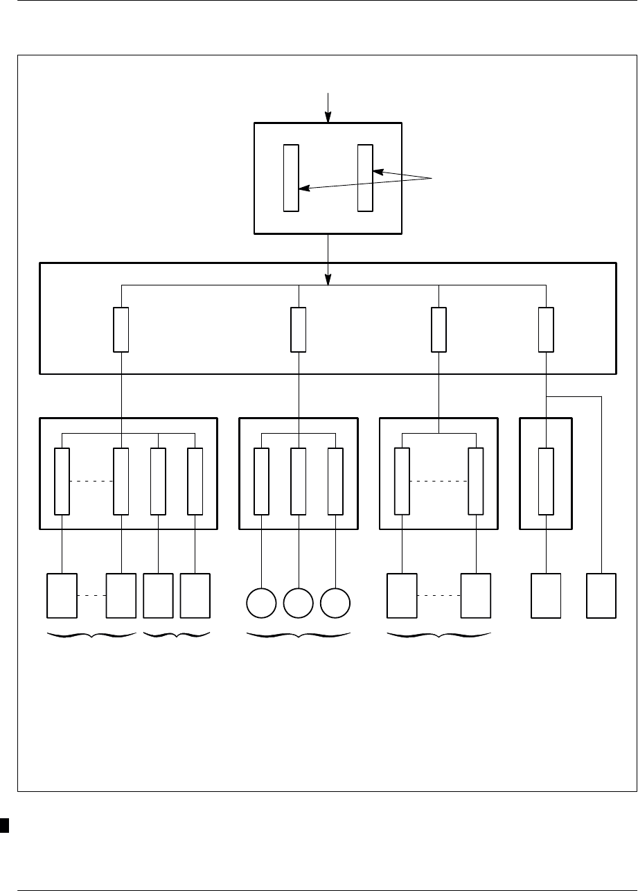
Cabinet description Nortel Networks Confidential
1–162
PE/DCL/DD/0063
411–9001–063 Standard 12.07/EN September 2000 GSM/BSS V12
PA_ICO FANICO DRX_ICO
8 power
amplifiers 2 F–type
converters 3 fans 8 DRXs (*)
dc input
50A
breaker
EMI filters
2.5A
breaker 5A
breaker
10A
breaker
dc compartment
Fuse 10A
Fuse 10A
Fuse 10A
Fuse 10A
Fuse 800mA
Fuse 800mA
Fuse 800mA
Fuse 2A
Fuse 2A
Fuse 4A
Legend:
PA–ICO : Power Amplifier interconnection
FAN–ICO : Fan interconnection
DRX–ICO : DRX (*) interconnection
BCF
or
CBCF
ALCO
or
RECAL
BCF or
CBCF
Note:
(*) DRX or e–DRX
Figure 1–122 S8000 Indoor BTS: dc power supply diagram

ArchitectureNortel Networks Confidential 3–1
S8000/S8002/S8006 BTS Reference Manual
3 ARCHITECTURE
3.1 Physical architecture
3.1.1 Introduction
This chapter provides an overview of the BTS physical architecture. BTS
components are described in detail in Chapters 1 to 5.
3.1.2 Subsystems
The BTS contains three main subsystems (see Figure 3–1 and Figure 3–2):
one BCF (Cabinet or Unit) or one CBCF Module
one TRX subsystem
one coupling system
The content of each subsystem is listed in Table 3–1.
3.1.3 Internal buses
The following buses, which connect BTS components, are described in this section:
Frequency hopping (FH) bus
Private PCM
GSM Time bus
Internal PCM bus
O&M bus
Note: The GSM Time bus, Internal PCM bus, and O&M bus are only used with
the BCF Unit.
Figure 3–1 shows the internal buses used with the BCF Unit and Figure 3–2
shows the buses used with the CBCF Module.

Architecture Nortel Networks Confidential
3–2
PE/DCL/DD/0063
411–9001–063 Standard 12.07/EN September 2000 GSM/BSS V12
Subsystem Contents*
Base Common Function (BCF)
Cabinet or Unit ** •Control and Switching Module (CSWM)
•Data Signalling Concentration board (DSC)
•PCM Interface board (PCMI)
•Synchronization board (SYNC)
•Alarm Collecting board (ALCO)
•Gateway (GTW)
Compact BCF (CBCF) Module ** •Compact PCM Interface board (CPCMI)
•Compact Main Common Function board
(CMCF)
•Remote Control Alarm (RECAL) board
•BCF Interconnection board (BCFICO)
•CBCF Back Panel (CBP)
TRX •Driver and Receiver unit (DRX or e–DRX)
•Power Amplifier (PA)
Coupling system •RF Combiner Module(s) of the following
types:
– Duplexer (D)
– Hybrid Two–way (H2D)
– Hybrid Four–way (H4D)
– Tx Filter(s) (TxF)
– eight–way cavity combiner (CC8)
•Rx Splitter(s)
•LNA Splitter
* The number of boards or modules are not indicated and depend on the
configuration of a site.
** The BTS contains a BCF or a CBCF.
Table 3–1 BTS subsystems
3.1.3.1 FH bus
The FH bus links together all logical DRXs (or e–DRXs)
The FH bus and the transmitters connected to it ensure the function of frequency
hopping and the filling of the BCCH frequency.
The FH bus is a V11 (series) bus. It is one-way and carries the signals according to
the RS485 standard.
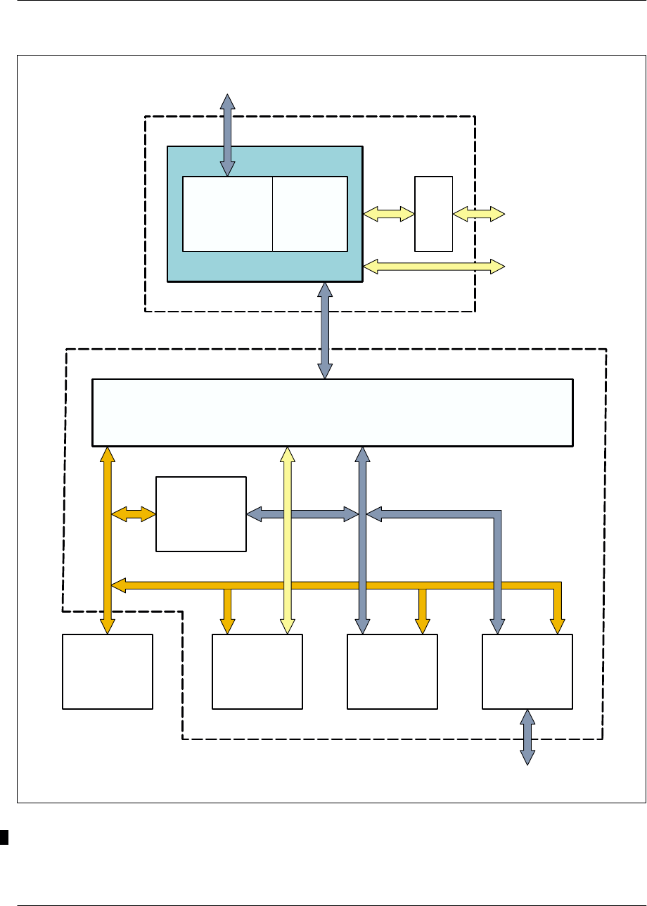
ArchitectureNortel Networks Confidential 3–3
S8000/S8002/S8006 BTS Reference Manual
GTW
CSWM
PCMIDSCSYNCALCO
FH bus
GATEWAY
Internal
PCM bus
O&M bus
GSM
TIME
bus
BCF
PA
DRX Logic
part
TRX
DRX Radio
part
DRX (*)
Transmitter coupler
subsystem
Reception coupler
subsystem
Private PCMs
Private PCMs
Note: (*) DRX or e–DRX.
Figure 3–1 Subsystem architecture with BCF
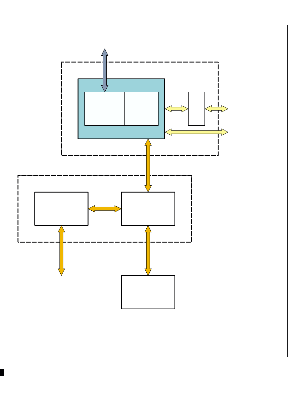
Architecture Nortel Networks Confidential
3–4
PE/DCL/DD/0063
411–9001–063 Standard 12.07/EN September 2000 GSM/BSS V12
PA
TRX
DRX (**)
DRX Logic
part
CPCMI CMCF
CBCF (*)
Private PCM
RECAL
DRX Radio
part
Private
PCMs
Note: (*) The two interconnection boards of the CBCF module (BCFICO and CBP) are not shown.
(**) DRX or e–DRX.
FH bus
Private PCMs
External PCMs
Transmitter coupler
subsystem
Reception coupler
subsystem
Figure 3–2 Subsystem architecture with CBCF
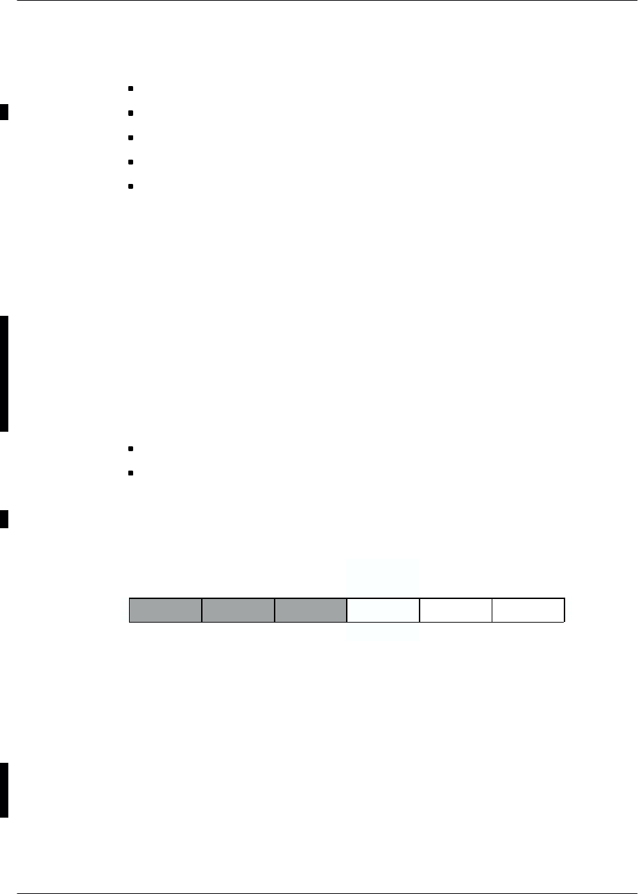
ArchitectureNortel Networks Confidential 3–5
S8000/S8002/S8006 BTS Reference Manual
Each message is transmitted in synchronization with the 4Fbit clock and includes
the following:
the system time in six bytes (flag included)
the address of the DRX (or e–DRX) that transmits the information in one byte
the code of the send frequency on 10 bits
the send power commands in one byte
the NRZ message of the send data in 19 bytes
Up to 16 transmitters can be connected to this bus.
For multi–cell sites, all the cells can be connected onto a single FH bus or there may
be one FH bus per cell, depending on the capacity of the site.
3.1.3.2 Private PCM
Up to six private PCMs transport data between the DRXs (or e–DRXs) and the BCF
unit or CBCF Module. Each Private PCM supports up to four DRXs (or e–DRXs).
Each Private PCM has a 64 kbit/s time slot (TS) distributed to all DRXs (or
e–DRXs) and carries the GSM TIME signal (TS31).
Each private PCM allocates the following time slots (TS) for each DRX (or
e–DRX):
three TSs (64 kbit/s logical channels) of transparent data (traffic/signaling)
one TS (64 kbit/s logical channel) processed by the gateway for the O&M
channel, an adaptation of the O&M bus of the CSWM card
A group of six TSs, three of which are used, is allocated to each DRX (or e–DRX),
as follows:
Traffic Traffic O&M TX
OML/RSL
1 2 3 45 6
TS 0 of the Private PCM is reserved for tests and supports no transmission channel.
A 4.096 MHz clock, slaved to the 4Fbit clock of the synchronization board, is used
for bit synchronization of the Private PCM.
The O&M channel
The O&M channel, not availabale with the COAM version of the BTS, is carried
by a TS of the private PCM and supports O&M data of the TXs. It is a duplex
two–way channel. Each TX has its own O&M channel, present on the only private
PCM that links the TX to the gateway.

Architecture Nortel Networks Confidential
3–6
PE/DCL/DD/0063
411–9001–063 Standard 12.07/EN September 2000 GSM/BSS V12
The private PCM TS number of the O&M channel of a DRX (or e–DRX) is
unvarying in a given gateway configuration. This TS number acts as the DRX (or
e–DRX) address for the gateway/DRX (or e–DRX) link.
O&M data are sent only on the O&M channel of the DRX (or e–DRX) selected on
the bus. Only the data received on this O&M channel are redirected to the O&M bus.
The GSM TIME channel
This one–way logical channel transports the GSM time signal to each DRX (or
e–DRX). It is carried by bit 7 of TS 31 of the Private PCM. The transmission speed
of the resulting transmission channel is 8 kbit/s.
A correction value is sent to each DRX (or e–DRX) over the OML link of the Private
PCM. This value corresponds to the delays caused by propagation. Each DRX (or
e–DRX) can therefore locally regenerate a synchronous GSM TIME bus with the
BCF subsystem bus.
The refresh period must be a multiple of an occurrence between the GSM time base
(577 µs) and the PCM time base (125 µs). The selected refresh period is 60 ms.
Such a 60–ms frame contains three parts:
Synchronization flag Useful data Filler bits
3.1.3.3 GSM TIME bus
Principle
The GSM Time bus is a V11 serial bus used in the BCF Unit to link the SYNC and
GTW boards.
The data it conveys define the “local BTS time”. The serial format includes a flag
to detect any break in the link. Moreover it provides a “strobe” every 577 µs that
accurately matches the start of each time slot.
Interface signals
The GSM TIME bus supports three types of signals. These three signals, which are
generated by the synchronization unit, are transmitted in differential mode.

ArchitectureNortel Networks Confidential 3–7
S8000/S8002/S8006 BTS Reference Manual
3.1.3.4 Internal PCM bus
Principle
The V11 bus is located between the switching matrix and the following units:
PCM Interface units (PCMI)
Data Signaling Concentration units (DSC)
GaTeWays (GTW)
The 16 internal PCMs are synchronous links at 2 Mbit/s on which the data are
organized in 125–µs frames divided into 32 time slots of eight bits each. A PCM
is a time division multiplexed link that supports 32 channels with a throughput of
64 kbit/s.
Interface signals
The signals used are the following:
•MICR : Receive PCM in master–to–slave direction
•MICE : Transmit PCM in slave–to–master direction
•SY : 8 kHz negative frame synchronization pulse
•H4M : 4.096 MHz timing clock
3.1.3.5 O&M bus
Principle
The O&M bus is a V11 asynchronous master–slave type bus that is subject to
physical addressing. It interconnects all units of the BCF subsystem and the TXs
through the private PCM between the GTW and the DRXs. The CSWM acts as
master.
The bus enables users to do the following:
set up the initial configuration and reset it
measure and control system status
retrieve alarms
force each bus subscriber to “RESET” status
Interface signals
The O&M bus is used in the BCF and originates from the CSWM card. Due to its
low rate (9600 bit/s), this bus is not matched.
The O&M bus contains ten logical signals:

Architecture Nortel Networks Confidential
3–8
PE/DCL/DD/0063
411–9001–063 Standard 12.07/EN September 2000 GSM/BSS V12
from master to slave:
–TX : asynchronous data transmitted by the master
–ADR[5..0]: six address lines giving the selected slave address from 00
to 63
–VAL : validation pulse, during which the address must be valid
(negative pulse)
–RAZ : initialization if this reset is pulsed during VAL pulse,
inhibition if the VAL is pulsed during the RAZ (active at
low level)
from slave to master:
–RX : asynchronous data received by the master
Each slave receives from the back–panel six signals, NUC[5..0], that allows it to
determine its address and to compare to the ADR[5..0]address.

ArchitectureNortel Networks Confidential 3–9
S8000/S8002/S8006 BTS Reference Manual
3.2 BCF functional architecture
Depending on the BCF physical architecture, the following functions are enabled
(see Figure 3–3):
control and switching
data channel concentrator
dual trunk interface
synchronization
alarm regrouping
3.2.1 BCF control, switching and management (CSWM)
3.2.1.1 Functions
The CSWM unit is duplicated for safety reasons, giving CSWMA and CSWMB.
The CSWM unit is the master BCF unit. It enables communication with the BSC,
organizes, stores and broadcasts all the data it receives from the BSC, supervises and
uses defense action on the equipment it controls. It must do the following (see
Figure 3–4):
set up communication with the BSC
manage BTS synchronization
manage the switching matrix
manage the FH bus
manage slave units (DSC, PCMI, ALCO, SYNC, GTW, and the TX part of the
TRX). Only the defense actions on slave processors is discussed below.
enable duplex operations
3.2.1.2 Setting up communication with the BSC
When the CSWM is activated, it must connect to the BSC to work. A link is set up
on an external PCM. Since a number of PCM links unite the BTS and BSC,
individual PCM links are frequently polled. If connection attempts fail on all the
available PCM, the CSWM resets.
3.2.1.3 Downloading
When the call has been set up with the BSC, the CSWM reports its status. The BSC
downloads the BTS if CSW code has not already been downloaded. The set of the
BCF downloadable files is formed by two catalogue files (BOOT & LOAD and
DLU), containing the list of the files, a configuration file and a file containing CSW
code.
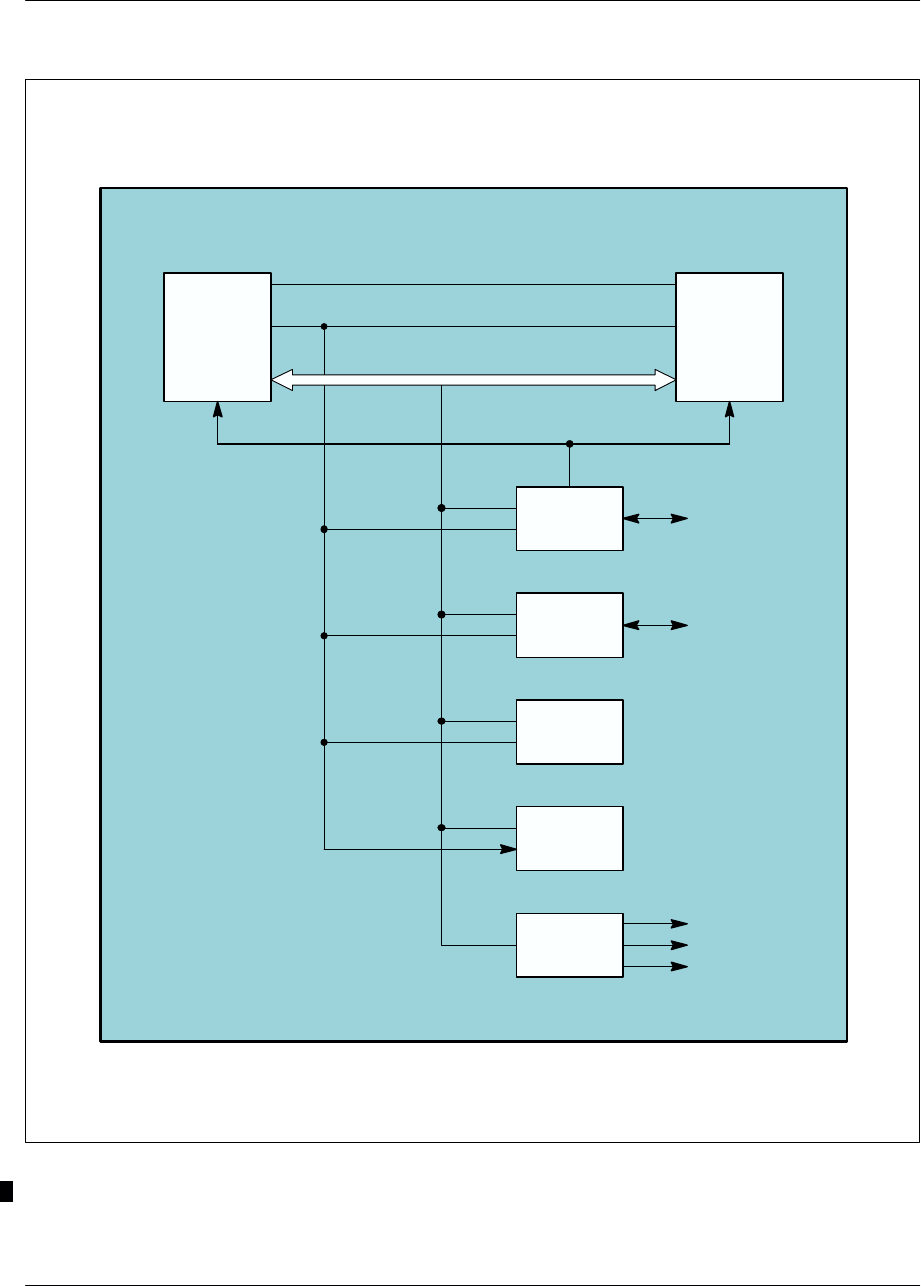
Architecture Nortel Networks Confidential
3–10
PE/DCL/DD/0063
411–9001–063 Standard 12.07/EN September 2000 GSM/BSS V12
GTW
PCMI
DSC
ALCO
CSWMBCSWMA
BCF
SYNC
External PCM
links to BSC
Power supplies
Cabinets
Site
Inter CSWM link
Internal PCM link
O&M bus
2 MHz clock
4 MHz clock
Private PCM
to DRX
Note: (*) DRX or e–DRX
Figure 3–3 BCF architecture

ArchitectureNortel Networks Confidential 3–11
S8000/S8002/S8006 BTS Reference Manual
BSC
CSWM
FH BUS
MANAGE-
MENT
TRANSMIT-
TER
MANAG.
CONCENTRATOR
MANAGEMENT
ALARM
UNIT
MANAG.
PCM
INTERFACE
UNIT
MANAGEMENT
PCM
SYNCHRONIZATION SWITCHING
MATRIX
TRANSMITTERS
CONCENTRATOR
ALARM BOARD
PCM
MANAGEMENT
BOARD
SYNCHRONIZATION
BOARD
SYNCHRONIZATION
MANAGEMENT
SWITCHING
MATRIX
MANAGEMENT
CSWM
SUPERVISION
DOWNLOADING
MANAGEMENT DUPLEX
MANAGEMENT
Other CSWM
GATEWAY
GATEWAY
MANAGE-
MENT
Figure 3–4 Organization of CSWM functions

Architecture Nortel Networks Confidential
3–12
PE/DCL/DD/0063
411–9001–063 Standard 12.07/EN September 2000 GSM/BSS V12
3.2.1.4 Synchronization management
At start–up, the CSWM chooses the first correct clock from among six. During
LAPD connection, the BTS forces the clock on the PCM carrying the LAPD.
3.2.1.5 Switching matrix management
The switching matrix management includes the following:
initialization
configuration
monitoring/defense
The switching matrix has 16 PCM links. Each PCM link has the following:
transmission test interface
reception test interface
idle interface
All 2n PCM time slots are connected to 2n+ 1 PCM time slots to allow PCM links
to be routed when the BTS are chained together (drop and insert technique).
Initialization
The 0 time slot on each PCM link is looped back on itself by the transmission test
interface, which is a hardware device that connects the PCM 0 time slot transmission
and reception on the reception interface.
The frames received and transmitted in each TS 0 over each PCM link are frequently
compared to allow the switching matrix to be tested at start–up time and its
performance to be monitored.
Configuration
The switching matrix is configured when the BSC requests the BCF to set up or
release a signaling or traffic channel.
Signaling channels are set up (or broken off) between an DRX signaling time slot
and a non–concentrated link on a signaling concentrator unit. This may entail
(dis)connection between a concentrated link on a signaling concentrator unit and
a PCM link time slot on a PCM interface.
Traffic channels are set up (or broken off) between a DRX traffic time slot and a
PCM link time slot on a PCM interface.
Monitoring/defense
The switching matrix is monitored by endless loops that are activated during the
initialization phase.

ArchitectureNortel Networks Confidential 3–13
S8000/S8002/S8006 BTS Reference Manual
If a fault occurs, the switching matrix is designated as faulty and switch over is
triggered.
The cause can be pinpointed from among the following:
switching matrix
internal PCM bus
idle interface
transmission test interface
reception test interface
3.2.1.6 FH bus management
The FH bus is connected to various DRX (or e–DRX) units.
Configuration
FH bus management becomes involved when the BSC sends cell configuration or
radio transmission configuration messages.
The CSWM uses the cell configuration message to construct the internal tables
needed for FH bus management.
The radio transmission configuration message is used to send monitoring masks to
transmitters used to check for frequency collisions and the flags on FH input
Monitoring/defense
FH bus management receives the frequency collision and no FH bus flag messages
sent by transmitters on the O&M bus.
Frequency collision messages cause an event report to be sent to the BSC (messages
are correlated to avoid repetition).
No FH bus flag messages result in the following:
a DRX (or e–DRX) fault when all the DRXs (or e–DRXs) detect the same event
a DRX (or e–DRX) fault when one event is detected
3.2.1.7 Transmitter–oriented CSWM defense actions
The CSWM undertakes defense action when it receives alarm messages or when the
scanner no longer detects transmitter activity.
If the faulty transmitter was configured (BCCH), the BTS sends an event report with
impact to the BSC; otherwise, the event report is without impact.

Architecture Nortel Networks Confidential
3–14
PE/DCL/DD/0063
411–9001–063 Standard 12.07/EN September 2000 GSM/BSS V12
3.2.1.8 DSC–oriented defense actions
The CSWM undertakes defense action when the DSC sends an event report on the
O&M bus or when the scanner no longer detects DSC activity.
The following faults can occur:
hardware fault
The DSC is faulty if any of its connections fail. Then the DSC is reset, and
external tests are run.
unexpected frames or queue overflow
The CSWM sends an event report to the BSC which takes the appropriate action.
loss on the O&M bus
The CSWM triggers defense action, the DSC is reset, and external tests are run.
A DSC is initialized by a reset command on the O&M bus. Start–up tests are run.
If the external test results are fault–free the DSC can be returned to the list of useable
units. If not, the unit must be replaced.
CSWM defense actions are determined in terms of equipment redundancy:
If there is no redundant DSC:
•if the DSC that is down supported O&M communication with the BSC. The
CSWM must isolate the faulty DSC by breaking off connections on the
switching matrix. The switching matrix restores communication with the
BSC on the same PCM as before. When communication is restored, the
CSWM informs the BSC that all communication previously established via
that DSC is lost and cannot be recovered. The BSC then takes the appropriate
action ;
•if the lost DSC did not support O&M communication with the BSC, the
CSWM must inform the BSC that all communications passing through this
DSC were lost and cannot be recovered. The next actions are determined by
the BSC.
If a redundant DSC is available, the CSWM breaks off faulty DSC connections
on the switching matrix and reconnects the redundant DSC to match the faulty
one. All the communication previously established via that DSC is restored and
an event report is sent to the BSC.
3.2.1.9 PCMI–oriented defense actions
In the event of a PCMI hardware fault, the CSWM activates self–tests by sending
the appropriate commands via the O&M bus. If the results of the self tests are
fault–free, the PCMI returns to operational status and the BSC is informed.
If the quality of transmission is the cause, the PCMI feeds back the information to
the BSC, whether it has been able to restore communication or not.

ArchitectureNortel Networks Confidential 3–15
S8000/S8002/S8006 BTS Reference Manual
3.2.1.10 ALCO board–oriented defense actions
If there is an ALCO card hardware failure, the CSWM restarts self–tests by means
of the commands available on the O&M bus. If the self–tests are successful, the
ALCO card is considered operational again and the BSC is informed.
3.2.1.11 Gateway switchover management
If there is a gateway failure, the gateways themselves determine state change
(passive ⇔ active). Then the fault signal is transferred to the CSWM via the O&M
bus.
Each gateway can send its status to the CSWM, either after a query from the CSWM
or spontaneously after switchover.
3.2.1.12 Duplex operation between CSWMs
The duplex function manages CSWM equipment redundancy in the BCF. The BSC
only perceives one CSWM at a time.
Redundancy is operated in passive/dynamic mode with hot restart:
The standby processor does not execute the same algorithms as the active
processor and does not receive the same message flow.
The active CSWM sends stable status information to the standby side. If a
problem arises on the active side, the standby CSWM takes over BCF control.
Switchover time includes the time needed to locate the fault, return to a stable
status, and restart processing.
Causes of switchover
Switchover may be triggered by hardware or software resetting. The watchdog
triggers hardware resetting, and software is reset by a software init message.
Hardware resetting may be triggered by the following:
a major hardware fault (CPU, memory units, etc.)
a serious software fault (address error)
Software resetting may be triggered by the following:
a minor hardware fault (switching matrix, internal PCM bus, O&M bus drivers)
a system software fault (dynamic memory overfilling)
Switchover procedure
The switchover procedure can only be performed in a stable system status. In the
event of switchover, the CSWM tries to return to the last stable condition. It checks
that its database (last stable state) and slave processor states (alarm units,
synchronization units, concentrator units, PCM interface units and transmitter
units) are consistent and may reconfigure them.

Architecture Nortel Networks Confidential
3–16
PE/DCL/DD/0063
411–9001–063 Standard 12.07/EN September 2000 GSM/BSS V12
Standby CSWM updating
The standby side is brought up to date in the following steps:
asynchronous software downloading
asynchronous data updating
synchronous data updating
The active CSWM side downloads standby CSWM software asynchronously
without disturbing operations on the active side.
Asynchronous data updating is performed in the following phases:
The active CSWM instructs the standby CSWM to reinitialize its database.
The active CSWM copies the database and sends it to standby side.
The active CSWM stores status transitions that occur during updating and sends
at the end of the sequence. It then starts synchronous updating.
Synchronous updating is performed each time the BSC sends configuration data or
when the CSWM performs defense actions.
The active CSWM sends one or more update messages to the standby side before
sending an acknowledgement or event report to the BSC.
3.2.2 Data Signaling Concentration unit (DSC)
The DSC is controlled by the CSWM. It communicates with the CSWM via the
O&M bus. It serves channel multiplexing, demultiplexing, and Operations and
Maintenance (O&M) functions.
3.2.2.1 Multiplexing and demultiplexing
The CSWM uses the DSC to set up communication between the BSC and the other
entities that make up the BTS. The LAPD protocol ignores the DSC that serves
concentrator and routing functions.
The DSC reads level 2 addresses (TEI) contained in LAPD frames and, using a
routing table, sends the information onto another time slot. The time slot may be
concentrated (a number of TEI arrive) or not (single TEI).
3.2.2.2 Operations and Maintenance (O&M) functions
Configuration
The CSWM sends the following to the DSC:
overall configuration
connect and disconnect configurations

ArchitectureNortel Networks Confidential 3–17
S8000/S8002/S8006 BTS Reference Manual
Overall configuration data includes the following:
the size of message queues
two queue overflow thresholds
the period defining the moment observation messages are sent
A connection configuration connects a TEI in a single time slot to a second
concentrated time slot.
Disconnecting may affect a TEI in a single time slot or in a concentrated time slot.
Disconnecting a concentrated time slot automatically triggers disconnection of
the concentrated TEI it contained.
Observations
The DSC returns its status to the CSWM as requested. The status report contains
overload alarms and hardware failures.
The DSC sends regular observation messages to the CSWM that contain the
following for the last traffic period and per time slot and TEI:
queue size
the maximum size reached by the queue
number of messages handled since the last status request
Tests
The DSC constantly tests unused time slots. It performs external loop tests on
CSWM request.
The results of unused time slot tests are returned to the CSWM in regular status
messages.
The CSWM may request the DSC to perform external tests. The DSC checks that
links are free and accepts (or refuses) start–up. The DSC returns the results of these
tests as requested.
Monitoring
The DSC supervises its own equipment parts and issues one the following fault
messages:
queue overload
receipt of unexpected frames
PCM link hardware malfunction

Architecture Nortel Networks Confidential
3–18
PE/DCL/DD/0063
411–9001–063 Standard 12.07/EN September 2000 GSM/BSS V12
Fault detection
The DSC receives two threshold values from the CSWM that give the overload
situation in message transmission queues. When queue thresholds are reached, the
DSC issues start and end–of–alarm messages to the CSWM on the O&M bus.
3.2.3 PCM Interface (PCMI)
The PCMI interfaces and synchronizes incoming and outgoing PCM links. It
converts the external PCM coming from the BSC into internal PCM used by the
BSC, and vice versa.
Each PCMI handles one external PCM link. A PCMI unit does the following:
converts external PCM links into internal PCM for BTS use
verifies link quality using error detection codes
matches impedance on the type of PCM link used by the operator
3.2.3.1 Configuration
The PCMI can operate without CSWM involvement. However, the CSWM sends
a configuration message on the O&M bus that contains the following:
the number of erroneous seconds, which defines a window used to evaluate PCM
alarms
threshold M1 for frame alignment error counters
threshold M2 for the CRC error counter
threshold M3 for coding type error counters
3.2.3.2 Monitoring
The PCMI monitors its own equipment and PCM links, and issues fault messages
concerning hardware alarms or PCM alarms.
3.2.3.3 PCM alarm management
Managing PCM alarm involves frame, multiframe, submultiframe, zero time slot,
and frame alignment; CRC is not managed yet.
A frame interval is 125 µs.
The duration of a multiframe is 2 ms, representing the time of 16 frames.
The length of a submultiframe is 1 ms.
The TS0 is set aside for the frame alignment signal, multiframe alignment bits, CRC
bits, and alarm sending.

ArchitectureNortel Networks Confidential 3–19
S8000/S8002/S8006 BTS Reference Manual
Frame alignment
Frame alignment is operated by the frame alignment byte occupying the TS0 in
every other frame.
Upon loss of frame alignment the alarm bit is set to 1 and the frame alignment
counter is increased.
The PCM alarms
Each PCM alarm corresponds to the detection of one anomaly type on the PCM
reception.
A seriously erroneous second is a second in which an NOS, SIA, RRA, or LOS
alarm condition occurred or an FE or CRC counter was overrun.
These alarms are indicated by LEDs on the front of the DTI board.
LOS: frame lock loss signal (LFA LED)
Frame lock is considered lost when three consecutive lock signals are received
with errors. This is also the case when bit 2 of TS 0 in frames that contain no
locking signal is received three times in a row with errors.
AIS: Alarm indication signal (AIS LED). Not used in the GSM 1900 frequency
band.
RRA or RAI: Remote Receive Alarm signal or Remote Alarm Indicator (RRA
LED).
NOS: no frame signal (NOS LED)
Upon detecting the beginning of an NOS fault signal, a 64–kbit/s SIA is
generated on each TS of the associated internal PCM link, an RRA is sent on the
external PCM link, and the application associates an NOS error to the errored
second, bringing on the NOS LED.
FE: Frame error (FE LED).
Used in case of 2 Mbit/s external PCM link. Error detection is effected only in
operation without CRC. The application counts the incorrect frame lock words
received, and compares them with the upper and lower thresholds
(programmable).
SKP: hop indication reception. Not used.
CRC: CRC error signal (CRC LED). Not used in the GSM 1900 frequency band.
The quest for CRC multiframe lock is associated with that for frame lock, to
ensure that the frame lock word found does indeed correspond to a single lock
word to which one can lock permanently.
The alarm LEDs on the front of the board are the LFA, AIS, RRA, NOS, FE, SKP,
and CRC. Each alarm event turns on the associated LED for a minimum time
of 200 ms.

Architecture Nortel Networks Confidential
3–20
PE/DCL/DD/0063
411–9001–063 Standard 12.07/EN September 2000 GSM/BSS V12
One cause is associated with each seriously erroneous second. The alarm cause is
defined in the following descending order of severity: NOS, AIS, LOS, RRA, FE,
CRC, and SKP.
When the number of seriously erroneous consecutive seconds reaches the number
of erroneous seconds (NBSEC) defined in the configuration message, the PCM is
designated in fault condition and a message is sent to the CSW.
The end–of–fault condition is the number NBSEC of consecutive seconds without
errors and the end–of–fault message is sent to the CSW.
3.2.4 Synchronization (SYNC)
The synchronization unit must synchronize the DRXs on a single reference time,
GSM time. It supervises the different defense stages. There are two identical
synchronization units, that have the same software (see Figure 3–5).
3.2.4.1 GSM time
The network supplies the reference time via three PCMI units. The CSWM selects
one of the six clocks and sends it to the synchronization unit. The clock selected
must have good long–term accuracy because it is used by the synchronization
module to generate reference time for the radio interface with an accuracy of
5 x l0–8.
If the external reference signal is absent, the CSWM selects a local clock derived
from the SYNC module active in “free running” mode.
3.2.4.2 Monitoring
The synchronization unit is monitored by its own control and monitoring
mechanisms, which check that the unit is operating correctly and GSM time is
available on the GSM TIME bus.
Alarms are as follows:
SYNO unit outage
CSWM clock failure
reference clock failure

ArchitectureNortel Networks Confidential 3–21
S8000/S8002/S8006 BTS Reference Manual
(CSWM) (SYNC)
(SYNC)
GTW
Synchronization
unit
Clock
selection
Internal
PCMs
Switchover
logic
Synchronization
unit
GSM TIME
channel
Private PCM
Local clock
Figure 3–5 GSM time bus synchronization

Architecture Nortel Networks Confidential
3–22
PE/DCL/DD/0063
411–9001–063 Standard 12.07/EN September 2000 GSM/BSS V12
The last two events are fed back to the CSWM. Defense actions are covered in
section dedicated to the CSWM.
In case of a synchronization unit fault, the synchronization units make the
switchover decision (active <=> standby). The fault is then fed back to the CSWM
over the O&M bus.
3.2.5 Alarm collecting function (ALCO)
3.2.5.1 Functions
The alarm collecting board (ALCO), located outside the BCF, collects internal and
external BTS alarms.
Internal alarms concern equipment parts on which the BCF does not use any
particular detection action, while external alarms are site–dependent.
These alarms are sent via the O&M bus to the BCF control unit, which redirects
them to the BSC.
The board also allows equipment located outside the BTS to be activated (future
use).
3.2.6 BCF/DRX gateway (GTW)
The gateway (GTW) carries out the following functions (see Figure 3–6):
adaptation of the frequency between the radio interface and the Abis interface
adaptation of the GSM TIME bus to the GSM TIME channel
adaptation of the O&M bus to the O&M channel for the TXs
management of the O&M protocol for the gateway as an O&M slave
management of part of the defense system
management of part of the switchover logic
initialization of the gateway board
3.2.6.1 Adaptation of the GSM TIME bus to the GSM TIME channel
This function consists in entering the GSM time on the GSM TIME bus, then
making calculations and carrying out formating to send the GSM time to the DRXs
by means of the GSM TIME channel.
3.2.6.2 Adaptation of the O&M bus to the O&M channel
This function consists in decoding the validation on the O&M bus of a dialogue
between the CSWM and the TX, and formating the characters sent and received on
the bus and the O&M channel.
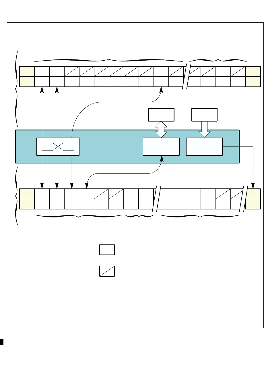
ArchitectureNortel Networks Confidential 3–23
S8000/S8002/S8006 BTS Reference Manual
T
1
T
2 3 4 5 6 7 8 9 10 27 28 29 30 31
OML/
RSL
T
1
T
2 3 4 5 6 7 8 3120 21 22 23 24
GSM
time
O&M/
TX TT TO&M
/TX
CSWM
O&M bus GSM TIME bus
Internal PCMs
(up to 8)
Private PCMs
(up to 6)
OML/
RSL
T
1st DRX (*) 3rd DRX (*)
1st DRX (*) 4th DRX (*)
2nd DRX (*)
O&M
conversion GSM time
conversion
SYNC
B
C
F
D
R
X
(*)
T
Key:
GTW
19
= traffic time slot
= unused time slot
0
0
SYN
SYN
Note: (*) DRX or e–DRX.
Figure 3–6 BCF/DRX Gateway (GTW)

Architecture Nortel Networks Confidential
3–24
PE/DCL/DD/0063
411–9001–063 Standard 12.07/EN September 2000 GSM/BSS V12
3.2.6.3 Management of the O&M protocol
This function provides the level 2 and 3 layers of the O&M protocol concerning
CSWM/gateway dialogue. The gateway is fully an O&M slave. It manages a
level–3 message dictionary.
3.2.6.4 Management of the defense
The software part of the gateway defense system essentially concerns detection of
minor and major faults which lead, respectively, to a ”light” software reset of certain
functions or passage to HALT state. A software watchdog system is also active.
3.2.6.5 Switchover management
The software’s role in switchover management is to send command codes to a
hardware logic circuit which controls gateway activation and de–activation.
3.2.6.6 Initialization
Initialization consists of configuring all peripherals present on the gateway board,
the communication controllers, the position of the GSM TIME channel, the
cross–connect matrix, and the transfer of certain initialization data from the PROM
to the RAM.
3.2.6.7 Multitasking organization
Most of the functions are not related to one another and therefore operate
completely asynchronously. In order for these functions to take place
simultaneously for the external environment, an internal function, transparent to the
outside, is needed to manage multitasking, hierarchized organization.
3.2.7 BCF configurations
The BCF exists in simplex or duplex configuration.
The following table gives the number of boards in every configuration.
Boards Simplex BCF Duplex BCF
CSWM 1 2 (1 active/1 passive)
PCMI 1 1 to 3
DSC 1 1 to 4
SYNC 1 2 (1 active/1 passive)
GTW 1 2 (1 active/1 passive)
Table 3–2 BCF configurations

ArchitectureNortel Networks Confidential 3–25
S8000/S8002/S8006 BTS Reference Manual
3.3 CBCF functional architecture
The CBCF performs the following functions:
switching, synchronization, and concentration
control of the alarm management unit
PCM Interface
The CMCF board performs the concentration, synchronization, and switching
functions. The CMCF also controls the alarm management unit (the RECAL
board), which is located outside the CBCF Module.
The CMCF board allows operation in duplex mode and in simplex mode.
The CPCMI board is the interface between the external PCM links (A–bis) and the
Private PCMs in the CBCF.
CBCF modes
The CBCF can be used in simplex mode with only one CMCF board in slot 0 or 1
running in active mode. Simplex/Duplex mode is managed by a micro switch on the
CMCF board. From duplex to simplex, the transaction in never automatic, it always
follows a configuration. From simplex to duplex mode, there is no automatic
transition when the active board detects the connection with the passive one.
3.3.1 Switching, synchronization, and concentration
The CMCF board is duplicated in the CBCF Module to provide redundancy (see
Figure 3–7).
One CMCF central processor manages the switching matrix and the
synchronization. The main processor and slave processor share the concentration
and routing tasks as described below.
3.3.1.1 Switching
The two switching matrices in the CMCF receive and distribute the traffic of
external PCMs as follows:
up to six PCMs communicate with the CPCMI boards
up to six PCMs communicate with the DRXs
two PCMs communicate with the processing units
one PCM to communicate GSM time
one PCM for tests
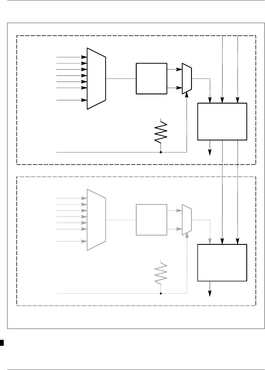
Architecture Nortel Networks Confidential
3–26
PE/DCL/DD/0063
411–9001–063 Standard 12.07/EN September 2000 GSM/BSS V12
1/256
1/193
H8M SY H4M
SYN
FLL
E1/T1
+ 5 V
1/256
1/193
H8M SY H4M
E1
+ 5 V
MASTER CMCF
SLAVE CMCF
PLL : Phase–locked loop
FLL : Frequency locked loop
SYN
PLL
SIX
CLOCKS
SIX
CLOCKS
Figure 3–7 CMCF board synchronization (full configuration)

ArchitectureNortel Networks Confidential 3–27
S8000/S8002/S8006 BTS Reference Manual
3.3.1.2 Synchronization
The CMCF provides synchronization to the radio part of the BTS.
Synchronization is obtained through a temperature–controlled oscillator that allows
the selection of timing signal from seven signals (six from the external PCMs, one
from an external source, and one from the CMCF master).
The selected clock signal is routed to a digital phase comparator that authorizes
synchronization operations in a frequency locked loop (CMCF master) or in a phase
locked loop (CMCF slave).
The CMCF slave operates in a phase locked loop so that its H4M clock is
synchronized with that of the CMCF master. This ensures that phase hopping does
not occur during a CMCF switchover.
GSM Time
The processing unit transmits the GSM Time every 60 ms. The GSM Time is
transmitted to the switching matrices of the CMCF master. The CMCF slave reads
the GSM Time in the CMCF master, which allows the synchronization of GSM
Time on both CMCFs.
Figure 3–7 shows the synchronization process on the CMCF board.
Switchover
A switchover occurs in synchronization with the H4M clock. Since the master
CMCF and the slave CMCF are synchronized (H4M and GSM Time), the
switchover does not cause a timing disruption.
The switchover sequence is as follows:
active CMCF becomes inactive
inactive CMCF detects the inactivity
inactive CMCF becomes active
A CMCF processor becomes inactive in the following circumstances:
H16M clock state is NOK and there is dual chain operation
the master request is disabled
master board is not properly connected to the back panel
the active processor is reset while in dual chain operation
Defence and redundancy management
A switchover from one CMCF board to the other in the event of an error on the active
CMCF board ensures redundancy. The hardware supports duplex and simplex
modes.
A redundancy channel between both CMCF boards ensures the exchange of data
between the boards in the event of a switchover.
The defense connectivity is shown in Figure 3–8.
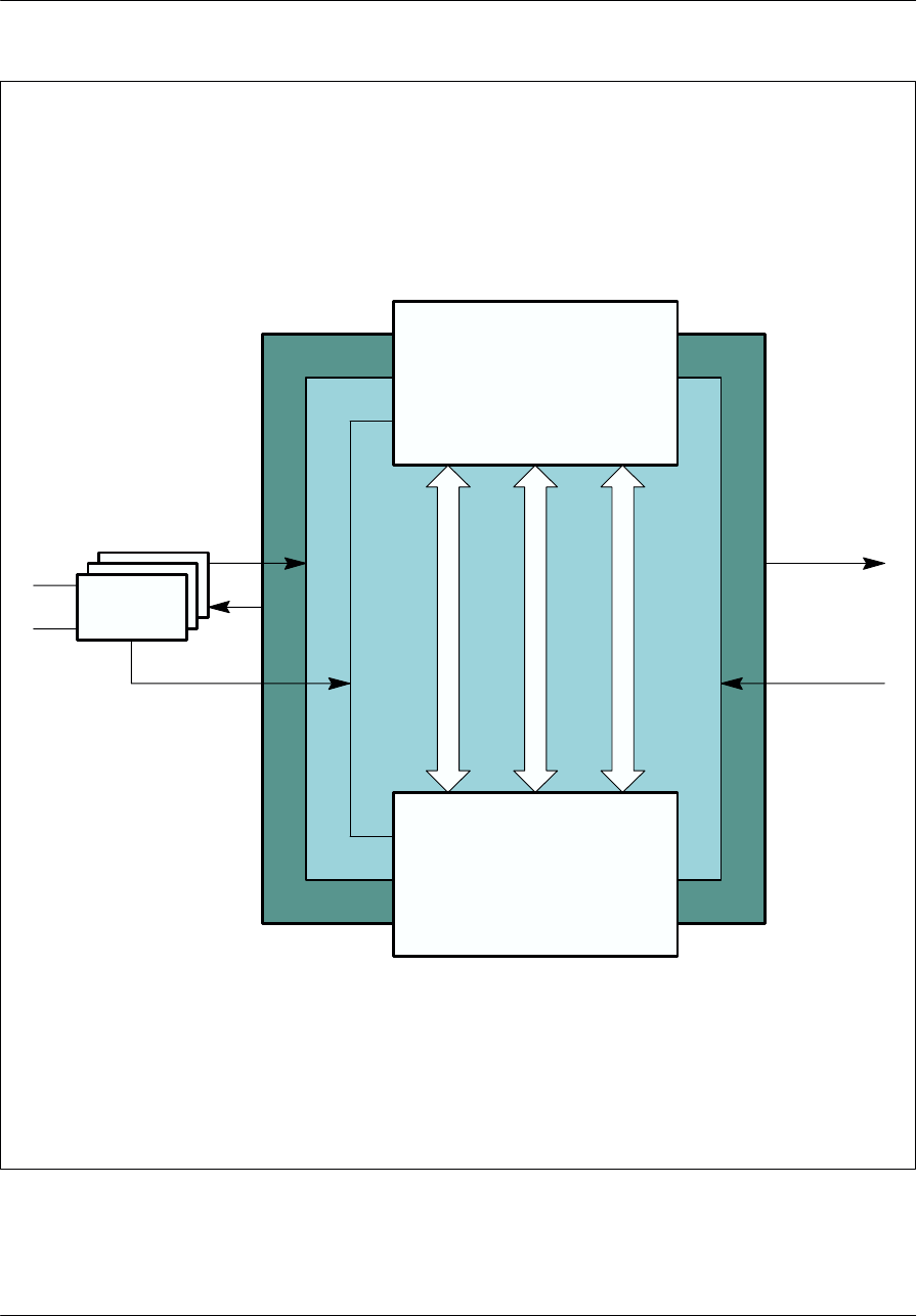
Architecture Nortel Networks Confidential
3–28
PE/DCL/DD/0063
411–9001–063 Standard 12.07/EN September 2000 GSM/BSS V12
MASTER CMCF
SLAVE CMCF
CPCMI
Six Private
PCMs
Six PCMs
Six Clocks
M/S logic witch
Duplex sync
Redundancy link
Figure 3–8 Defense connectivity between the CMCF boards (full confguration)

ArchitectureNortel Networks Confidential 3–29
S8000/S8002/S8006 BTS Reference Manual
3.3.1.3 Concentration and routing
The concentration and routing functionality is performed by the master and slave
processing units. The master processing unit manages the board ressources. The
slave processing unit, which operates synchronously with the master unit, manages
one PCM, one HDLC link (for master–slave communication), and one RS232 link.
The master processing unit receives a external clock signal at 4.096 MHz and
generates a 33 MHz reference frequency. This frequency is supplied to the slave unit
so that it can be synchronous with the master unit.
3.3.2 Control of the alarm management unit
The CMCF manages the alarm management unit, the RECAL board, located
outside the CBCF Module.
The RECAL board collects internal and external alarms and routes them to the
CMCF, which routes to the BSC.
The communication between the CMCF and the RECAL is done using a LAPD
protocol link that uses a channel supported by time slot 25 of PCM0.
3.3.3 PCM Interface
Up to three CPCMI boards provide the interface between six external PCM links
(A–bis) and six Private PCMs used inside the CBCF Module.
The interface tasks corresponds to an electrical level translation and a frame format
conversion depending on the type of external PCM link (PCM E1, PCM T1, or
HDSL).
The external PCM interface has functional blocs that perform the following
functions:
conversion of analog signals on the A–bis interface and the logical signals of the
Framer part of the PCMI
management of the synchronization clock
transposition between the A–bis and the Private PCMs signals
3.3.3.1 Signalling interfaces
The CPCMI board uses the PCM and HDSL interfaces described below.
PCM A–bis interface
The E1 interface is compatible with the G703 Recommendation. Its impedance is
120 (two pairs of bidirectional symmetrical links) or 75 Ohms (coaxial cables).
The T1 interface is compatible with ANSI T1.403 and T1.102. Its impedance is
100 Ohms (two pairs of bidirectional symmetrical links).

Architecture Nortel Networks Confidential
3–30
PE/DCL/DD/0063
411–9001–063 Standard 12.07/EN September 2000 GSM/BSS V12
HDSL A–bis interface
The HDSL–E1 format (2B1Q) is on one single twisted copper pair where the
transmission rate is 2320 kbps for a full E1 frame. This rate is compatible with the
ETSI ETR 152 RTR/TM–06002 standard.
The HDSL–T1 format (2B1Q) is on one single twisted copper pair where the
transmission rate is 1552 kbps for a full T1 frame. This rate is not standardized and
is considered a proprietary link.
Private PCMs
One CPCMI board is connected to two Private PCM links (PCM0 and PCM1). The
O&M communication is done through an HDLC link using TS0 of PCM0.
E1/T1
Three bits supplied to the CMCF indicate whether the board is an E1 or T1.

ArchitectureNortel Networks Confidential 3–31
S8000/S8002/S8006 BTS Reference Manual
3.4 DRX functional architecture
The DRX board has a digital part, a radio part and a power supply board
(Figure 3–9)
3.4.1 DRX digital part
The DRX digital part consists of four units:
the Advanced MaNagement Unit (AMNU) which manages the DRX
the Digital Control Unit for eight chanels (DCU8) which is the signal processing
unit
the Time Base Unit (BDT) which manages the GSM_TIME for the DRX
TX logic which is the interface with the transmission part in the DRX Radio
board
3.4.1.1 AMNU unit
The AMNU unit manages the DRX. It manages the eight time slots of an TDMA
frame, and the radio signaling functions.
These functions can be broken down into communication functions (RSL), on the
one hand, and operating and maintenance functions (O&M), on the other (see
Figure 3–10).
Communication functions
Communication functions include:
routing functions
concentration functions
Routing functions
The TDMA frame management unit routes messages from the BSC. The messages
arrive on the RSL and can be broken down into two categories:
messages concerning processing of a single time slot
messages concerning all the time slots in the TDMA frame
Concentration functions
There are two types of messages:
transparent messages
non–transparent messages
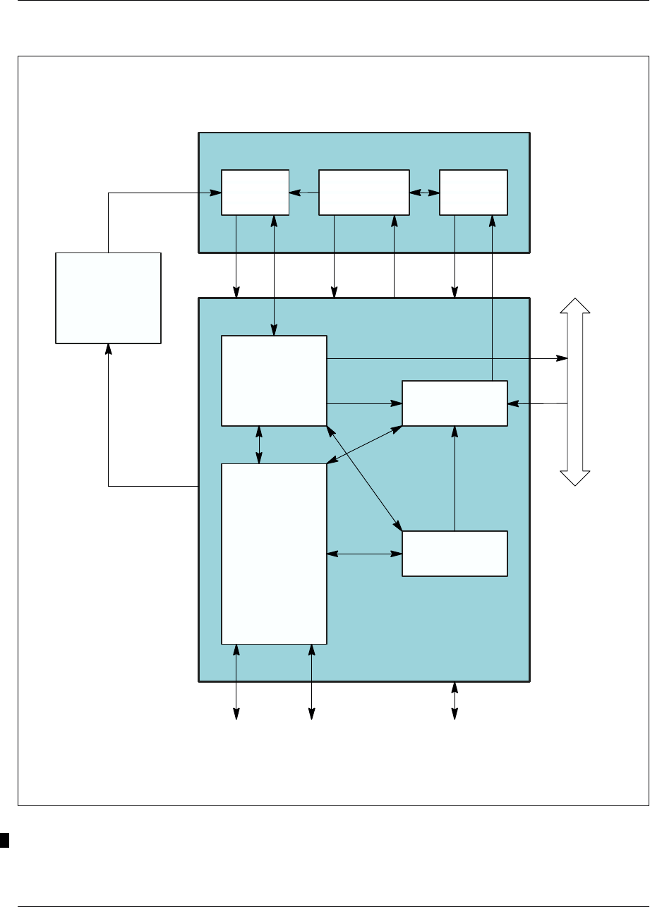
Architecture Nortel Networks Confidential
3–32
PE/DCL/DD/0063
411–9001–063 Standard 12.07/EN September 2000 GSM/BSS V12
AMNU
DCU8
RX
Test Ethernet
BDT
DRX digital
FH
bus
Privte PCM
Radio DRX
Logical TX
TX
Power
supply
board
+ 5.4V
+ 12V
– 12V
+ 48Vdc
Frequency
reference unit
Figure 3–9 DRX board: functional block diagram
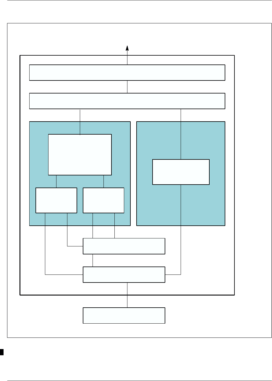
ArchitectureNortel Networks Confidential 3–33
S8000/S8002/S8006 BTS Reference Manual
SPU
AMNU
BSC
O&M
Communication
function (RSL):
– routing
– concentration
Level 1 radio access
Level 1 radio
Level 2 radio management
Radio
resources
management
Radio
measurements
management
Operations &
Maintenance
functions (O&M)
Level 3 radio
Level 1 wires
Level 2 wires
Figure 3–10 AMNU functions

Architecture Nortel Networks Confidential
3–34
PE/DCL/DD/0063
411–9001–063 Standard 12.07/EN September 2000 GSM/BSS V12
Transparent messages are simply concentrated on a time slot of the internal PCM.
Non–transparent messages are:
radio measurement messages of the mobile
interference measurement messages on the inactive channels
load messages on the RACH channel
load messages on the PCH channel
Non–transparent messages are transcoded, averaged and grouped in a single
message to the BSC. This message is sent to the same time slot as the transparent
messages.
Operation & Maintenance functions
The following Operation & Maintenance functions are processed by the Frame
management unit (AMNU):
start–up, downloading, initialization
configuration
monitoring/defense
Start–up/Downloading/Initialization
The AMNU is started by a hardware reset or a reinitialization message sent by the
BSC. It causes configuration of the LAPD and establishment of the OML link with
the BSC.
The DRX subsystem can be downloaded only after that the BCF is downloaded and
that the units of site management of cell management and of Abis signaling of the
DRXs have been configured.
The BSC systematically initiates a downloading phase of the catalogue files and of
the following software units:
AMNU
SPU
DLU
BOOT
TX
BDT
BIST of the SPUs
Follows a re–flashing of the units for which the software versions are different.

ArchitectureNortel Networks Confidential 3–35
S8000/S8002/S8006 BTS Reference Manual
Configuration
The DRX is configured by the BSC by means of an OML link on the Abis interface.
Configuration can be broken down into:
a general configuration:
•configuration of the TDMA frame
time slot configurations:
•configuration of radio time slots
•configuration of the frequency hop
Configuration of the TDMA frame provides the DRX with parameters shared by
the whole cell, such as:
cell identity (BSIC)
BCCH frequency
indication of frequency hopping implementation
cell type (normal or extended)
and with parameters specific to the DRX:
the frequency of the TDMA frame if there is no frequency hopping
indication of implentation of diversity in reception
The TDMA frame cannot be dynamically configured. A change of configuration
requires re–start of the downloaded software.
The configuration of the radio time slot specifies the type of logical channel to use
for a time slot.
The configuration of the frequency hopping specifies, for a time slot, the list of
frequencies to use, as well as sequencing. This configuration is optional and only
appears if the frequency hopping was requested in the TDMA frame configuration.
Monitoring
The BSC regularly sends status requests to the DRX to detect any problems on the
OML link.
LAPD break
The LAPD, OML and RSL links are monitored by a timer. If level 2 loss is detected,
the BSC and the AMNU try to reconnect. If connection has not been made by the
end of the time–out, the AMNU is reinitialized.

Architecture Nortel Networks Confidential
3–36
PE/DCL/DD/0063
411–9001–063 Standard 12.07/EN September 2000 GSM/BSS V12
Event reports
The AMNU collects all events detected by the DRX equipment. It performs
filtration, and error reports to the BSC. Transmission error reports, and fault
management on RX–splitters alarms are sent through the BCF or CBCF.
The AMNU filters to prevent repetition of non–transient events, which means it can
send the BSC a single indication.
The AMNU sends errors to the BSC by sending ”event report” messages. There are
two types of these messages:
transient messages which are not acknowledged by the BSC
non–transient messages which must be acknowledged by the BSC and which are
repeated by AMNU until they are acknowledged.
Radio signaling function
The radio signaling function supports two Signal Processing Units (SPU). Each
SPU manages one time slot.
Two versions of the SPU software are available. One corresponds to propagation
conditions in rural area and the other to propagation conditions in urban area. For
the rural areas, the algorithm parameter equals zero where as it is set at the value
0.5 for urban areas. In this later case, the interferer cancellation algorithm is active.
The radio signaling functions can be broken down into four groups of functions:
level 1 radio access
level 2 radio management of LAPDm signaling
level 3 radio management, which is made up of two functions:
•radio resources management
•radio measurements management
operation & maintenance
Level 1 radio access
Level 1 radio access makes it possible to manage dialogue between the AMNU
signaling function and the SPU processors which are connected to the AMNU. It
offers:
configuration of operating modes for each SPU
SPU control
transmission and reception of data on the radio channel, respecting methods for
slaving to the radio frequency.
Level 2 radio management
Level 2 radio management manages the LAPDm level 2 signaling on the radio
channels.

ArchitectureNortel Networks Confidential 3–37
S8000/S8002/S8006 BTS Reference Manual
Radio resources management (radio level 3)
Radio level 3 provides the following functions:
level 2 management on the common channels
control of level 2 functions on dedicated channels
activation of the common channels
organization of the Common Control CHannel (CCCH), including chaining and
repetition of paging messages and transmission of dedicated channel allocation
messages
activation or deactivation of dedicated channels, implementation of encryption
and channel mode changes
providing SPU processors with system information on the SAACH and BCCH
channels
detection of ”random access” and ”handover access”
detection of radio link attenuation (monitoring of the upstream SACCH
channel), verifiable by the OMC
sending of the mobile transmission power change
Radio measurements management (level 3 radio)
This provides the following functions:
return of interference measurements carried out by the SPU processors on the
inactive dedicated channels and transmission of these measurements to the
AMNU
concatenation of measurements made by the SPUs on the active dedicated
channels and those transferred by the mobile over the same period
Operation & maintenance functions (O&M)
These functions provide configuration and deconfiguration of the time slots and
frequency hopping functions.
3.4.1.2 DCU8 unit
The DCU8 unit consists of two signaling processing chains, A and B, as shown in
Figure 3–11. Each chain handles four calls in full–rate voice mode and eight calls
in half–rate voice mode. Chain A and chain B are connected to a subassembly, the
BB_FILT ASIC, which is the interface with the radio part and filters reception
samples before sending them to the two chains. A second subassembly, the CHIF,
which is associated with the BB_FILT ASIC, calculates encryption and decryption
masks.
Chain A processes even radio reception time slots and odd radio transmission time
slots. Conversely, chain B processes odd radio reception time slots and even radio
transmission time slots.

Architecture Nortel Networks Confidential
3–38
PE/DCL/DD/0063
411–9001–063 Standard 12.07/EN September 2000 GSM/BSS V12
BB_FILTCHIF
RAM
AMNU
DSP DECOD DSP DECOD RAM
DSP TRANS DSP TRANS
RAM RAM
Receivers
FH bus
GSM TIME bus
SPU (A Chain) SPU (B Chain)
DSP EGAL
DPRAM DPRAM
Figure 3–11 DCU8 unit diagram

ArchitectureNortel Networks Confidential 3–39
S8000/S8002/S8006 BTS Reference Manual
The DCU8 unit has five DSPs:
one EGAL DSP, which equalizes the reception signal
two DECOD DSPs, which handle reception signal decoding, and level 1
sequencing
two TRANS DSPs, which handle transmission signal processing, encoding, and
the interface with the remote transcoder
There is one DECOD DSP and one TRANS DSP in each chain.
SPU
The SPU carries out processing associated with the transmission layer, and to this
end, it executes a certain number of functions, such as: (see Figure 3–12 and
Figure 3–13):
demodulation of GMSK signal at reception
ciphering/deciphering of sent and received data
encoding/decoding and interleaving/de–interleaving of data from the various
channels
encoding/decoding of voice and data (from 13 kbit/s to 16 kbit/s and vice–versa)
transfer of discontinuous transmission (DTX) signal
control of transmitters and receivers
processing of radio measurements
Demodulation function
Demodulation consists of extracting, from the GMSK signal received, the binary
data transmitted, that is 144 bits for a normal burst and 36 bits for an access burst.
This is done for the eight time slots of the radio channel.
The demodulation principle selected takes into account the inter–symbol
interference resulting from smoothing of the transmission phase transitions
(limitation of the transmitted spectrum), multiple path phenomena, and distorsion
introduced by the channel filter upon reception.
Implementation of this type of demodulator requires modification of the
transmission channel as concerns pulse response, frequency deviation, and
reception times. Determining these parameters is part of the job of the demodulation
function.

Architecture Nortel Networks Confidential
3–40
PE/DCL/DD/0063
411–9001–063 Standard 12.07/EN September 2000 GSM/BSS V12
AMNU
SPU
Demodulation
Deciphering (optional)
De–interleaving
Decoding
Speech/data
or signaling
Speech/data
08.60 format coding
Signaling
Receiver
management
DRX radio
Figure 3–12 SPU reception functions
SPU
AMNU
08.60 format
decoding
Transmitter
management
Coding
Interleaving
Ciphering (optional)
Signaling Speech/data
DRX radio
Figure 3–13 SPU transmission functions

ArchitectureNortel Networks Confidential 3–41
S8000/S8002/S8006 BTS Reference Manual
The receiver has the space diversity function. Both received channels are combined
in an equalizer which carries out joint equalization.
For each of these channels, the pulse response as well as the C/I+N ratio are
estimated. These ratios are used to weight the predictions and samples of each
channel.
The symbols from the equalizer are then decrypted, de–interleaved and decoded to
restore the control messages and traffic sent by the mobile.
Ciphering/deciphering function
The fluxes of binary symbols sent and received on each time slot on the TCH or
SDCCH are encrypted one bit at a time, in compliance with the
ciphering/deciphering algorithm.
The ciphering or deciphering operation protects confidentiality of voice and
signaling. It consists of adding binary bits, one by one, between sent and received
data and a binary train (the ciphering sequence), generated from a ciphering key and
the TDMA frame number of the time slot.
Encoding/decoding and interleaving/de–interleaving functions
All traffic and control logic channels are encoded to protect useful information
against transmission errors. Each channel has its own encoding scheme, usually
including the following steps for each block:
protection of data bits with parity bits or a block code
encoding of the ”data bits + check bits” unit with a convolutional code; this
operation gives encoded bits
rearrangement and interleaving of the encoded bits
burst formating
For data, the encoding procedure depends on the rate: the interleaving level is
higher for data than for voice.
Some channels do not use the encoding schemes described above, in particular the
RACH, FCCH and SCH channels, for which the notion of interleaving on several
times slots does not exist.
Mobile transmission timing advance function
The BTS must measure the delay on the received signal when the mobile station
makes itself known.
This measurement, known as timing advance, is forwarded in the dedicated channel
assignment message (immediate assignment) to the MS, which uses this parameter
to anticipate its transmission timing.

Architecture Nortel Networks Confidential
3–42
PE/DCL/DD/0063
411–9001–063 Standard 12.07/EN September 2000 GSM/BSS V12
During the call establishment, the BTS computes the timing advance value and
sends it within CHANNEL REQUIRED message to the BSC. If this value is above
the threshold, then the BSC rejects the call establishment.
In ongoing call conditions, the timing advance is calculated at regular intervals and
sent to the MS over the downlink SACCH channel.
The calculation is based on the following:
other measurements taken during demodulation
the timing advance used by the mobile station that is returned in the layer 1
header of the uplink SACCH
Discontinuous transmission (DTX)
Discontinuous transmission allows signals to be sent over the radio channel alone
when a speech signal is present. This limits interference and MS power
consumption. For each call, the MSC indicates whether the BSS “does not use” or
“may use” the DTX.
The principle behind discontinuous transmission is as follows:
The base or mobile vocoder has a Voice Activity Detector (VAD) that detects if the
frame constructed every 20 milliseconds contains speech. If the frame does not
contain speech, the vocoder constructs a special frame called the SIlence Descriptor
(SID) that contains all the background noise description elements. This frame is sent
to produce a comfort noise at the far end, and radio transmission stops.
The vocoder periodically reassesses the ambient noise and reconstructs the SID
frame. The frame produced in this way is sent in step with the SACCH (once every
four 26-frame multiframes (480 milliseconds)).
When the vocoder detects new speech activity, a special SID frame indicating the
End Of Silence (EOS) is sent, and normal speech frame sending resumes.
On the receive end, additional processing sequences interpret the incoming traffic
frame types (speech, SID, FACCH, nothing) using the related flags (BFI, SID, TAF)
and perform the appropriate operations.
The DTX is allowed for data in non-transparent mode.
BCCH filling
The BCCH frequency must be transmitted continuously so mobile stations can
perform field strength measurements in neighbouring cells.
Continuous transmission is accomplished in the following ways:
When frequency hopping is not used, the TRX uses the BCCH frequency as the
carrier frequency for all the channels it supports. The TRX sends fillers on the
BCCH frequency although it may have nothing to send in a given time slot.

ArchitectureNortel Networks Confidential 3–43
S8000/S8002/S8006 BTS Reference Manual
When frequency hopping is being used, one of the following occurs:
•The hopping laws authorize permanent BCCH transmission, and all the TRXs
help fill operations.
•The hopping laws do not authorize permanent transmission and a transmitter
is required to enable BCCH “filling” independently and take over when the
hopping laws step down.
Note: That the laws that enables permanent transmission on BCCH are only
accepted by cavity coupling.
Transmitter and receiver control
The SPU controls a transmitter and a receiver. It calculates the frequency hopping
law and determines the frequencies to synthesize.
The transmitter is controlled by the FH bus. The SPU sends the following to the
transmitter:
the power and frequency to use
the bits to send
the time synchronization signal
The SPU sends the following to the receiver:
the frequency to use for the following time slot
the synchronization clock signal
the GSM TIME synchronization signal
The SPU receives the following from the receiver:
digitized samples from the reception channel
the scale factor (gain)
the receiver alarms
Radio measurement processing
The Radio Measurement Processing performed by the BTS ensures that the network
and the mobiles can communicate with each other with minimum interference at the
lowest possible transmission power and with the best transmission quality.
Measurements processed by the BTS include signal strength and signal quality. The
mobile takes measurements in the downlink direction (BTS –> MS), while the BTS
takes them in the uplink direction (MS → BTS). Other measurements include signal
strength on the BCCH frequency of the surrounding cells and the MS_BS distance.
The BTS averages these measurements for each connection. The averaged
measurements are then used as the basis for a decision–making process for the
following:

Architecture Nortel Networks Confidential
3–44
PE/DCL/DD/0063
411–9001–063 Standard 12.07/EN September 2000 GSM/BSS V12
power control
call clearing
inter–cell handover
intra–cell handover
The BTS cyclically sends to the BSC the interferences measures done on the
inactive channels.
BB–FILT ASIC
The BB_FILT ASIC constitutes the interface between the signal processing unit
(SPU) of the DRX and the radio RX module on the one hand, and the enciphering
ASIC on the other hand. It carries out the band–pass filtering of the digital samples
output by the radio RX module, and generates the FH bus.
A single BB_FILT ASIC processes all eight TSs of the radio frame.
The functions provided by this ASIC include:
GSM time reception interface providing the synchronization of the DSPs on the
radio frame
on transmission:
•recording of the TX parameters and of the ciphering key, supplied by the DSP
EGAL
•transfer of the ciphering key to the CHIF ASIC
•reading of the ciphering template from CHIF ASIC
•ciphering of the parameters and transmission on the FH bus
on reception:
•recording of the RX parameters and of the ciphering key, supplied by the DSP
EGAL
•programming of RX hopping synthesizers
•generation of channel and sampling frequency selection signals for the analog
to digital converter
•base–band filtering of the digital samples delivered by the a dc converter
•selection of the best gain for each channel (normal and diversity)
•transfer of these selected filtered samples to the DSP EGAL
•transfer of the deciphering key to the CHIF ASIC
•reading of the deciphering template from CHIF ASIC, and transfer of the
template to the DSP EGAL
3.4.1.3 BDT unit
The BDT (time base) unit regenerates GSM TIME signals. The GSM time is
distributed to the BDT unit of each DRX by means of the GSM TIME channel of
the private PCM, every 60 ms.

ArchitectureNortel Networks Confidential 3–45
S8000/S8002/S8006 BTS Reference Manual
The value of the propagation delay is sent to the DRX by means of the OML link
of the private PCM. From these two data, each DRX makes the necessary
corrections and regenerates the GSM TIME bus.
If, for any reason, the GSM time is not distributed on the BDT unit, the BDT unit
locally maintains the GSM TIME bus signals and continues to provide the GSM
time to the DRX units.
The BDT unit is made up of a logic block and a calculation block.
Digital block
The BDT unit receives a 26 MHz clock signal derived from the radio unit clock. This
clock signal has the same stability properties as the 4Fbit clock signal provided by
the BCF synchronization board and is more stable in the short term. The digital
block generates the following signals:
H4M (4.096 MHz)
STRTM (recurrent pulse at 577 microseconds)
TIME_DATA (containing T1, T2, T3 and TN)
Calculation block
The calculation block synchronizes the H4M and STRTM signals with the
synchronization unit signals of the BCF. In addition, it updates the values T1, T2,
T3 and TN.
The synchronization principle consists of forcing a divider–by–24 counter to divide
by 23 (if the BDT is slow) or by 25 (if it is fast). This way, every 23 or 25 periods
of 26 MHz (depending on whether the slow BDT is accelerated or the fast BDT is
slowed down), the BDT corrects a period of 26 MHz.
3.4.1.4 TX logic unit
The main role of the TX logic unit is to control the radio subassembly in real time.
It receives the BCF configuration commands from the AMNU. It carries out the
processing and sends back reports.
Once configured, the TX logic unit reads, on each time slot, the data present on the
FH bus. Then it calculates the frequency code and the power code to be used with
the radio interface.
Transmission power
In general, radio power is determined by two inputs. One controls the maximum
static power and the other gives the dynamic attenuation at each time slot.
The static power is given by the BCF or CBCF in the CONFIG message. The TX
calculates attenuation to compensate for cable loss between the TX–driver and the
power amplifier.
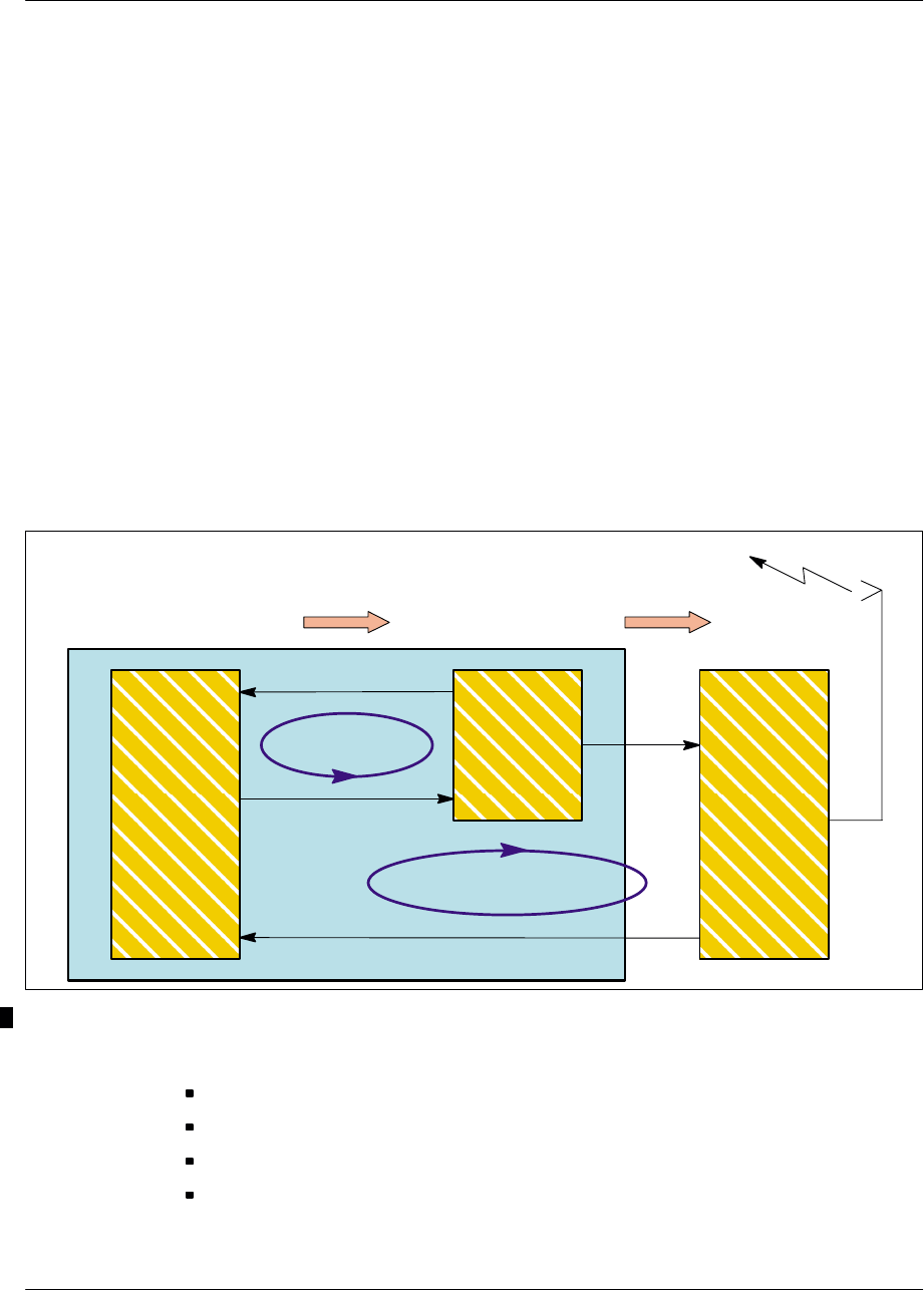
Architecture Nortel Networks Confidential
3–46
PE/DCL/DD/0063
411–9001–063 Standard 12.07/EN September 2000 GSM/BSS V12
The dynamic power is provided by the ASIC of the TX logical unit. Its software
reads the value and commands the TX–driver accordingly.
In the case of a BCCH filler, the additional attenuation introduced is always zero.
The power values that the TX and the mobile have to use are fixed by the BTS
according to a control algorithm using the measurements results that it makes and
the thresholds stockpiled in the OMC. The mobile and the BTS power control can
be inhibited by the OMC.
The power control aim is to minimize the interferences, ensure good transmission
quality and save mobile’s batteries.
Power slaving
The setpoint value is slaved to compensate for gain variations of the transmission
chain.
Two slaving loops are used to compensate for attenuation in the gain chain (see
Figure 3–14).
DRX
TX LOGIC
External loop
GMSK Modulation
Internal loop
Radio Frequency
Antenna
TX DRIVER
Control bus PA or LPA
Figure 3–14 Power slaving diagram
These loops may be in the following states:
Open: This state is used for calibration of the internal loop with the external loop.
Initialization: This state is used for loop start–up.
Error: A loop is in error when it is not longer in correspondence with the setpoint.
Closed: A loop is closed when it is in slow slaved mode.

ArchitectureNortel Networks Confidential 3–47
S8000/S8002/S8006 BTS Reference Manual
3.4.2 DRX radio part
The DRX radio part is composed of a power supply board and of the DRX radio
board.
The power supply is converting common -48 V to specific +5 V/± 12 V power
supply signals for the DRX radio board.
The DRX radio board is composed of three units:
the Frequency reference (Fref) unit
the receiver unit (RX)
the transmitter unit (TX)
3.4.2.1 Frequency reference unit
The reference frequency for all local oscillators is derived from the Fref frequency
supplied by the VCXO, itself derived from the 4.096 MHz signal provided by the
DRX digital part (BCF or CBCF).
It provides a very steady and spurious–free reference clock for the RX/TX hopping
and fixed synthetizers (13 MHz signal).
3.4.2.2 Receiver unit (RX)
The receiver unit (RX) has four main functions. Slot–to–slot frequency hopping is
achieved with a dual synthetizer arrangement (one is active while the other one is
setting to the following frequency):
signal down conversion from radio frequency band to Intermediate Frequency
(IF) then to base band frequency
channel filtering (in IF)
RX–level dynamic management
digitization of the base band signal
The base band signal is then sent in binary form with its scale factor to the DRX
digital part.
Receiver configuration
The receiver configuration is done by the DRX digital part, which sends:
the reception frequency to be used for the following time slot
the synchronization clock signal
the GSM time synchronization signal
Receiver monitoring
The receiver monitors internal equipment: microprocessor and Phase Lock Loops
(PLL).

Architecture Nortel Networks Confidential
3–48
PE/DCL/DD/0063
411–9001–063 Standard 12.07/EN September 2000 GSM/BSS V12
If there is a failure or other problem, it generates an alarm:
microprocessor fault
frequency range not respected (if the frequency to synthesize as requested by the
DRX digital part is incorrect)
PLL loss of alignment (if one of the receiver PLLs is not aligned)
3.4.2.3 Transmitter unit (TX)
The Transmitter unit has two main parts:
IF and RF chains
gain control loop (or Automatic Level Control)
IF and RF Chain
An I/Q modulator with a Local Oscillator (LO) phase–locked on a reference
frequency transposes the two baseband I/Q signals into the IF chain.
This 125 MHz local oscillator (LO_IF) phase–locked on a 13 MHz signal translates
the baseband signals into an intermediate frequency. (The IF is 125 MHz in
GSM 900, 286 MHz in GSM 1800 and 299 MHz in GSM 1900).
The second LO is used for up conversion from IF to RF.
The up–conversion is followed by bandwidth filter, amplifier stages, variable
voltage attenuators, and digital attenuators.
Gain Control Loop (or Automatic Level Control)
The driver transmit chain upholds the accuracy of the transmission power
compatible with the GSM recommendations against time.
The control dynamics use two components: one voltage variation attenuator (VVA)
and a step–by–step digital attenuator taking target attenuation into account and
compensating for it.
The Automatic Level Control also includes the PA.
3.4.3 DRX shutting down
3.4.3.1 DRX soft blocking
The DRX soft blocking consists in setting a DRX “out of service” without stopping
the calls established on this DRX. If possible, an intra–cell handover is performed
for those calls to release the DRX more quickly. Otherwise, the DRX will be
released after the normal completion of the calls.

ArchitectureNortel Networks Confidential 3–49
S8000/S8002/S8006 BTS Reference Manual
3.4.3.2 DRX soft blocking coupled with a forced handover
To speed up the DRX shutting down, the DRX soft blocking can be coupled with
a forced handover. The calls will be handed over a neighbour cell if the signal
strength is over the handover threshold for that cell.
3.4.3.3 Hint
The two actions mentionned above can be performed into a unique command to a
better efficiency of the DRX shutting down.
3.4.4 Power supply board
The power supply card provides a dc voltage between 40.5 V and 57 V, to be
converted into +5 V, +12 V and –12 V. The 48 V voltage is sent first to the logical
DRX unit converter, then, after filtering, to the logical DRX unit and the radio DRX
unit converter.
The power supply of the board varies according to the DRX types and on the
frequencies.
The mechanical and electrical grounds are linked to the common reference zero
volts.

Architecture Nortel Networks Confidential
3–50
PE/DCL/DD/0063
411–9001–063 Standard 12.07/EN September 2000 GSM/BSS V12
3.5 e–DRX functional architecture
The e–DRX board consist of (see Figure 3–15):
an e–LDRX digital board including a dc/dc converter, a frame processor TX
logic (GMSK and 8–PSK modulation), and a local time base, working for all
frequency bands
an e–RDRX radio board including a dc/dc converter, a low power driver and a
dual receiver
3.5.1 Modifications between the DRX and e–DRX
This chapter describes the modifications between the current DRX and the e–DRX.
The main features of the e–DRX are the following:
signal processing capacity improvement
8–PSK modulation compatibility
receive dynamic extension
TX output power dynamic reduction
packet backhaul readiness
3.5.1.1 E–LDRX board modifications
The main modifications concerning the e–LDRX board are the following:
the migration of BDT, AMNU, and TX into a single FPGA
the use of one PowerQuicc
the introduction of the 52 MHz frequency reference function
the use of two DSP
the extension of the memory capacity (8 Mb for SDRAM, 4 Mb for flash and
2 Mb for SRAM)
the size reduction and integration of the dc/dc converter on the e–LDRX board
the lower power consumption (<15W)
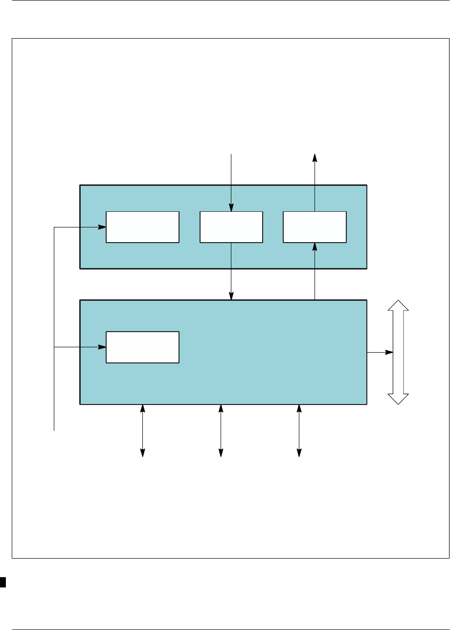
ArchitectureNortel Networks Confidential 3–51
S8000/S8002/S8006 BTS Reference Manual
RX
Ethernet
e–LDRX digital board
FH
bus
Private PCM
e–RDRX radio board
TX
DC/DC
converter
DC/DC
converter
Debug
Radio
reception Radio
transmission
Power
supply
Figure 3–15 e–DRX board: functional block diagram

Architecture Nortel Networks Confidential
3–52
PE/DCL/DD/0063
411–9001–063 Standard 12.07/EN September 2000 GSM/BSS V12
3.5.1.2 E–RDRX board modifications
The main modifications concerning the e–RDRX board are the following:
the removal of the 104 MHz frequency reference
the use of RXIC2 module (IF => BF transposition)
the RX dynamic extension provided by an AGC (–13 to –110 dBm)
the TX output power dynamic reduction
the integration of the dc/dc converter on the e–RDRX board
the lower power consumption (<15W)
3.5.2 Main external connections
3.5.2.1 Private PCM
A private internal PCM is used to link the e–DRX to the BCF. The proprietary
interface has the same definition as the previous internal PCM, except that the clock
is fully synchronous with the radio interface.
This bus carries the following informations:
Radio Signaling Link (RSL) and local Operation and Maintenance (O&M) on
one time slot
Traffic links on two, three, four, six or eight time slots
GSM_TIME channel on a separate time slot
The feature allows the e–DRX to be remotely controlled.
3.5.2.2 FH bus
The FH bus is connected to the various e–DRX units.
3.5.2.3 Power Supply
The e–DRX is powered by a –48V dc supply and the typical consumption is 25W.
3.5.2.4 Test links
The e–DRX has an Ethernet port and an asynchronous serial port. It also has serial
lines for emulator connections, and real time trace facilities.
3.5.2.5 RF interfaces
The e–DRX unit provides RF reception with diversity and RF transmission at low
level.

ArchitectureNortel Networks Confidential 3–53
S8000/S8002/S8006 BTS Reference Manual
3.5.3 e–DRX functional description
This chapter describes the functional architecture of the e–DRX, but does not detail
each part. The aim is to give enough information to approach easily the main
features.
3.5.3.1 Logic unit (e–LDRX)
The logic unit (e–LDRX) contains (see Figure 3–16):
a FPGA unit which provides:
•a control and switching management function
•a time base function
•a synchronization function
a management unit (AMNU) which processes the following functions:
•start–up, downloading, initialization
•configuration
•monitoring
•LAPD break
•event reports
a transmission unit which provides:
•a radio signaling function
•a signal processing function
•a power regulation function
•a RX logic function
•a TX logic function
FPGA unit
Control and switching management function
Setting up communication with the BSC
When the BTS is activated, it must be connected to the BSC to work. A link is set
up on an external PCM link.
Downloading
When communications have been set up with the BSC, the BTS reports its status.
The BSC downloads, if necessary, the software to the BTS.

Architecture Nortel Networks Confidential
3–54
PE/DCL/DD/0063
411–9001–063 Standard 12.07/EN September 2000 GSM/BSS V12
RX logic function TX logic function
Transmission
unit
FPGA unit
Logic unit (e–LDRX)
Processing signal
function
(SPU)
Radio signaling
function Power regulation
function
Management unit (AMNU)
Synchronization
function Control and switching
management function Time base
Radio unit (e–RDRX)
Figure 3–16 Logic unit (e–LDRX): functionnal architecture

ArchitectureNortel Networks Confidential 3–55
S8000/S8002/S8006 BTS Reference Manual
Synchronization management
At the start–up, the BTS selects the clock. During LAPD connection, the BTS forces
the clock onto the PCM carrying the LAPD.
Switching matrix management
Each PCM link managed by the switching matrix has a transmission test interface,
reception test interface, and an idle interface
The switching matrix is configured when the BSC requests to set up or to release
a signaling or traffic channel from the BTS.
Signaling channels are set up (or broken) between a transmission signaling TS and
a non–concentrated link. This operation may entail (dis)connection between a a
concentrated link TS coming from the BTS and a PCM link TS on the PCM
interface.
Traffic channels are set up (or broken) between a transmission traffic TS and a PCM
link TS on the PCM interface.
Data signaling concentration function
The BTS uses this function to set up the communication between the BSC and the
other entities that make up the BTS. This function is implemented with the LAPD
protocol that serves concentrator and routing functions.
Time base
The time base regenerates the GSM_TIME bus with information issued from the
GSM_TIME channel.
If, for any reason, the GSM time is not distributed to the time base, this one
maintains the GSM_TIME bus signals locally and continues to provide the GSM
time to the logic unit.
Synchronization function
The synchronization function must synchronize the transmissions on a single
reference time: GSM _TIME.
The network provides a radio reference clock via two PCM links. This clock
selected has good long–term accuracy. It’s the reason that the synchronization
module to generate an exact reference time for the radio interface uses this clock..
If the external reference signal is missing, the BTS selects the local clock.
The synchronization function is monitored by internal control and monitoring
mechanisms. They check that the synchronization is operating correctly and that the
GSM time is available on the GSM_TIME bus.

Architecture Nortel Networks Confidential
3–56
PE/DCL/DD/0063
411–9001–063 Standard 12.07/EN September 2000 GSM/BSS V12
AMNU Unit
Start–up, downloading, initialization
The AMNU unit is started by a hardware reset or a re–initialization message sent
by the BTS. It configures the LAPD and establishes an OML link with the BSC.
Depending the BTS request, the BTS systematically initiates a downloading phase
of the catalogue files and software units.
Follow by a re–flashing of the units for which the software versions are different.
Configuration
The transmission is configured by the BSC via the BTS.
The configuration provides:
a general configuration. It contains the configuration of the TDMA frame and
provides the logic unit parameters shared by the whole cell, such as:
•cell to identity (BSIC)
•BCCH frequency
•indication of frequency hop implementation
•the frequency of the TDMA frame if there is no frequency hopping
a configuration of the radio TS. It specifies the logic channel type to use for TS.
a configuration of the frequency hop. It specifies, for TS, the list of frequencies
to use, as well as sequencing. This configuration is optional and only appears if
the frequency hop was requested in the TDMA frame configuration.
Supervision
The BTS regularly sends status requests to detect any problems.
LAPD break
A timer monitors the LAPD with the OML and RSL links. If level two loss is
detected, the BSC and the AMNU try to reconnect. If connection is not
re–established before the end of the time–out, the AMNU is reinitialized.
Event reports
The AMNU:
collects all events detected (internal or external alarms)
provides the filtration and reports errors (transmission/reception) to the BSC
provides the filtration to prevent repetition of non–transient events, which means
it can send to the BSC a single indication

ArchitectureNortel Networks Confidential 3–57
S8000/S8002/S8006 BTS Reference Manual
The AMNU sends errors to the BSC by sending ”event report” messages through
the BTS. There are two types of these messages:
transient messages which are not acknowledged by the BSC
non–transient messages which must be acknowledged by the BSC and which are
repeated by AMNU until they are acknowledged
Transmission unit
Radio Signaling function
The main characteristics of this function are described below:
the radio access management (level 1)
It manages a dialog between the AMNU signaling functions and the signal
processing functions (SPU1 and SPU2) which are connected to the AMNU.
the radio management (level 2)
It manages the LAPDm level 2 signaling on the radio channels.
the radio resources management (level 3)
It provides mainly the level 2 management on the common channels and control
of level 2 functions on dedicated and common channels.
radio measurements management (level 3)
It provides the return of interference measurements carried out by the two
signal–processing units on the inactive dedicated channels and transmission of
these measurements to the AMNU.
Operation & Maintenance functions (O&M)
They provide configuration and unconfiguration of the TS and frequency
hopping functions.
Signal Processing function
The signal processing (SPU) function performs processing associated with the
transmission layer executes a number of functions, such as:
modulation/demodulation (8–PSK)
ciphering/deciphering of sent and received data
coding/decoding and interleaving/de–interleaving of data from the various
channels
mobile transmission timing advance function
discontinuous transmission (DTX)
BCCH filling
transmitter and receiver control

Architecture Nortel Networks Confidential
3–58
PE/DCL/DD/0063
411–9001–063 Standard 12.07/EN September 2000 GSM/BSS V12
Power regulation function
Its main function is to check instantly the associated radio subset. It receives
configuration instruction via the AMNU unit. In this case, it launches processing
and returns reports.
Once that the function is configured, each TS in attendance on the FH bus is reading.
Next the function calculates the frequency and the power code to be applied to the
radio interface. Each function act a control of the set point (emission power), to
improve the non–linearity of the gain of the transmission chain.
It launches these main operations:
frequency hopping management
power slaving
transmission power
alarms management
RX logic function
The logic functions:
maintain:
•the interface between the SPU functions with respectively the RX radio
functions on the radio unit (e–LDRX)
•and the ciphering
filter the digital samples, provided by the RX radio functions, to base band
signals
generate the FH bus
Each RX radio functions processes the eight TS of the radio frame.
The main characteristics of the RX1 and RX2 radio functions are:
an interface for the reception of the GSM time to maintain the DSP
synchronization on the radio frame
for the transmission:
•the recording transmission parameters and the cyphering key
•the parameters cyphering and the transmission on the FH bus
for the reception:
•the recording of the reception parameters and the ciphering key
•the base band filtering of the digital samples provided by the converter
•the ciphering key moving
TX logic function
They maintain the interface between the SPU functions and respectively the TX
radio functions of the radio unit (e–LDRX).

ArchitectureNortel Networks Confidential 3–59
S8000/S8002/S8006 BTS Reference Manual
3.5.3.2 Radio unit (e–RDRX)
The radio unit (see Figure 3–17) processes the radio channels for
transmission/reception function.
TX radio function
The transmitter module contains the transmission channels of lower power which
manage the Radio Frequency (RF) signals and Intermediate Frequency (IF) signals
as follows:
I/Q modulation
IF filtering and amplification
IF and RF transposition
RF band filtering
amplification and variable attenuation
output power control
RX radio function
The reception module includes the reception radio channels which manage the RF
and the IF signals as follows:
RF signals from LNA–splitter
RF to IF transposition
IF channel filtering and amplification
RF to BF transposition
Analog–to–digital conversion
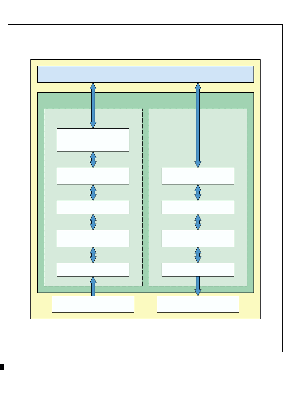
Architecture Nortel Networks Confidential
3–60
PE/DCL/DD/0063
411–9001–063 Standard 12.07/EN September 2000 GSM/BSS V12
Amplification RX module
(LNA–Splitter) Amplification TX module
(LPA)
Radio unit
(e–RDRX)
RX1 (RF)
RX2 analog–to–digital
converter
Logic unit (e–LDRX)
TX1 (RF)
Frequency translation
(IF/RF)
RX1 (IF) TX1 (IF)
RX radio
function TX radio
function
Frequency translation
(LF/IF) Frequency translation
(LF/IF)
Frequency translation
(IF/RF)
Figure 3–17 Radio unit (e–RDRX): functional unit

Software descrIptionNortel Networks Confidential 4–1
S8000/S8002/S8006 BTS Reference Manual
4 SOFTWARE DESCRIPTION
4.1 BTS software presentation
BTS software is divided into downloadable files and an onboard PROM.
4.1.1 Downloadable files
The BSC downloads these files via the A–bis interface.
There are two sets of files, BCF and DRX (or e–DRX). Each set is arranged in a file
catalogue that contain the list of files and the files themselves.
4.1.2 PROM
PROM chips are read-only memory units used to store software.
They are all installed on all BTS equipment boards.
4.1.2.1 S8000 BCF software
Boards serving the BCF are described in Table 4–1:
Board Software product
name Software product
type
CSWM PE_CSWM_B
PE_CSWM_L BOOT
LOAD
PCMI PE_BS_DTI_E1
or
PE_BS_DTI_T1 PROM
SYNC PE_SYN PROM
DSC PE_DCC PROM
GTW PE_GTW PROM
ALCO PE_BS_ALO PROM
Table 4–1 BCF software product names
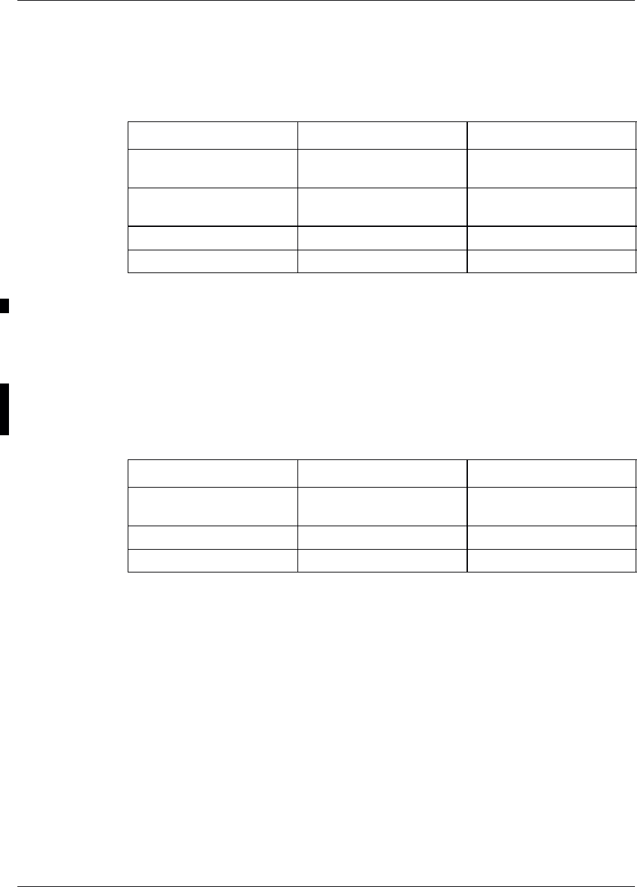
Software descrIption Nortel Networks Confidential
4–2
PE/DCL/DD/0063
411–9001–063 Standard 12.07/EN September 2000 GSM/BSS V12
4.1.2.2 S8000 BTS CBCF Software
The software product associated with the boards and slaves of the CBCF Modules
are listed in Table 4–2.
Board Sofware product name Software product type
CBCF Module PE_CBCF_B
PE_CBCF_DLU0 Boot
DLU Code
CPCMI PE_CPCMI_E1
PE_CPCMI_T1 Load
Load
RECAL PE_RECAL Load
CC8 PE_CC8_1800 Load
Table 4–2 CBCF software product names
4.1.2.3 S8002 BTS CBCF software
The CBCF software package includes the PROMs installed in the slave units and
the CMCF software which divides itself into two parts called BOOT and LOAD.
All the CBCF files are downloadable as listed in Table 4–3.
Board Sofware product name Software product type
CBCF Module PE_CBCF_L
PE_CBCF_B Load
Boot
CPCMI PE_CPCMI Load
RECAL PE_RECAL Load
Table 4–3 CBCF software product names

Software descrIptionNortel Networks Confidential 4–3
S8000/S8002/S8006 BTS Reference Manual
4.1.2.4 S8000 DRX/eDRX Software
As listed in Table 4–4, the software products vary depending on whether the BCF
or CBCF is used in the BTS. DRX O&M software is used with the BCF. DRX
COAM is used with the CBCF or BCF from V12 onward.
Board Sofware product name Software product type
DRX O&M/COAM PE_AMNU_COAM_L
PE_AMNU_RSL_L
PE_AMNU_B
PE_SPU2G_EGAL1_L
PE_SPU2G_EGAL2_L
PE_SPU2G_1620_L
PE_SPU2G_BIST
PE_SPU2G_BIST_1620
PE_TX_L_COAM
PE_BDT_L
PE_TOOLS
O&M AMNU LOAD
RSL AMNU LOAD
AMNU BOOT
SPU EGAL1
SPU EGAL2
SPU 1620
BIST SPU
BIST SPU 1620
TX
BDT
PL TOOLS
e–DRX Informations not available Informations not available
Table 4–4 S8000 BTS: DRX AND e–DRX software product names
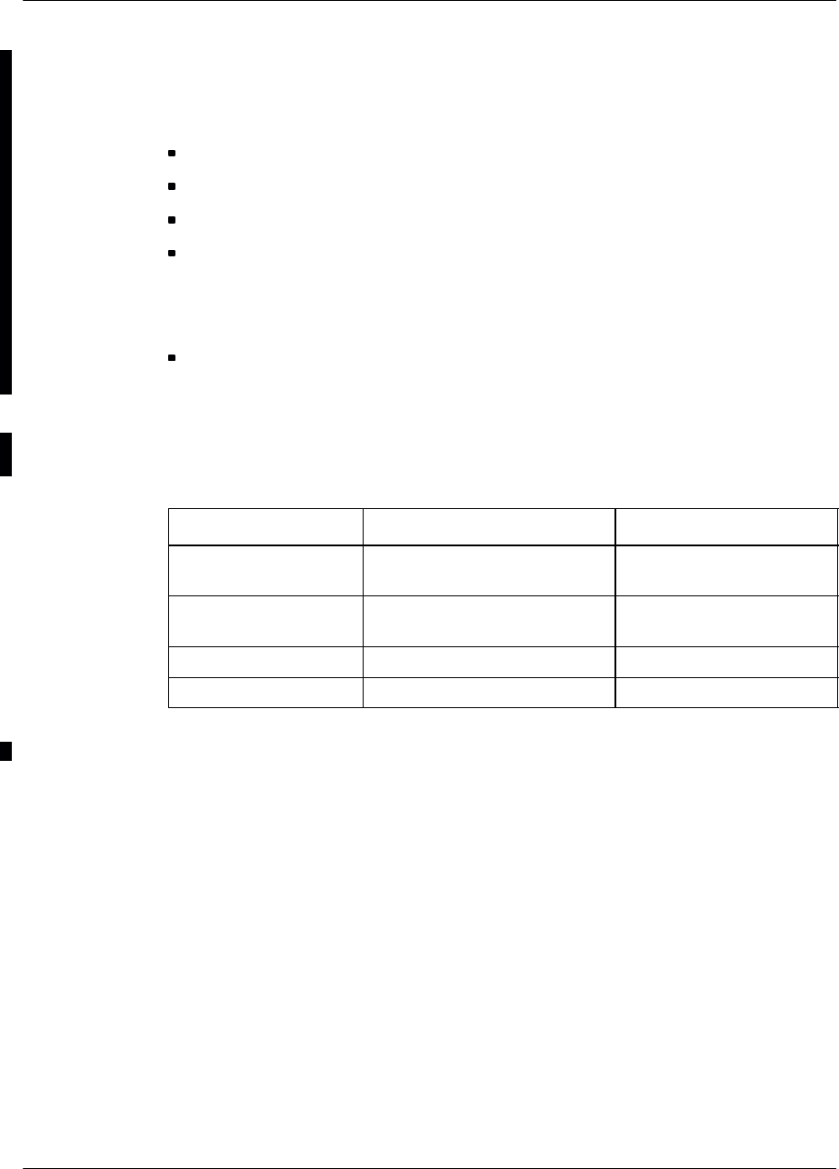
Software descrIption Nortel Networks Confidential
4–4
PE/DCL/DD/0063
411–9001–063 Standard 12.07/EN September 2000 GSM/BSS V12
4.1.2.5 S8002/S8006 BTS DRX/e–DRX software
The software products AMNU, SPU, DLU, BOOT, TX, BDT and BISTs are listed
below:
AMNU: It is the DRX/e–DRX management unit.
SPU: it enables level 1 radio communication with the mobile.
BDT: It extracts the GSM TIME carried on the private PCM.
TX: It manages and monitors radio transmission. it is installed on each DRX
board. It defines the FH bus input from which the TRX reads data, and defines the
transmission power to be used. it also forwards TX alarms to the CMCF and
controls the Power Amplifier (PA).
BISTs: Basis hardware self test programs of a BTS subsystem. An exemple is the
AMNU BIST which tests the components of the AMNU such as memory.
AMNU, BISTS, TX BOOT, BDT BOOT, and optionnally Cyphering ASIC
softwares are installed in factory.
Board Sofware product name Software product type
AMNU PE_AMNU_L
PE_AMNU_B Load
Boot
SPU PE_SPU2G_EGAL_2
PE_SPU2G_DLU_DCS Load
Load
TX PE_TX_L_GSM Load
BDT PE_BDT_L Load
Table 4–5 S8002 BTS: DRX software product names

Software descrIptionNortel Networks Confidential 4–5
S8000/S8002/S8006 BTS Reference Manual
Board Sofware product name Software product type
AMNU PE_AMNU_COAM_L
PE_AMNU_COAM_B
PE_AMNU_BOOT_BOOT
PE_BOOT_INTER
PE_AMNU_RSL_L
PE_AMNU_OML_L
Load
Boot
Boot Boot
Boot
RSL AMNU Load
O&M AMNU load
SPU PE_SPU2G_1620_L
PE_SPU2G_BIST_1620 Load
Bist
TX PE_TX_L_COAM
PE_TX_OM_L Load
TX O&M Load
BDT PE_BDT_L Load
PE_TOOLS PL Tools
Table 4–6 S8006 BTS: DRX software product names
Note: The e–DRX informations are not available

Software descrIption Nortel Networks Confidential
4–6
PE/DCL/DD/0063
411–9001–063 Standard 12.07/EN September 2000 GSM/BSS V12
4.2 BTS software functions
BTS software is distributed among three major units (see Figure 4–1 and
Figure 4–2):
The DRX (or e–DRX) unit is designed to transmit and receive (modulate and
demodulate) and manage TDMA frames on the radio channel.
The CBCF and BCF manage their slave units:
•CBCF: CPCMI, RECAL, DRX (or e–DRX), CC8
•BCF: ALCO, DSC, DRX Interface, PCMI, Tx, and SYNC
The TIL unit is used for in–factory testing of the BTS, and to configure, control,
and supervise the BTS on site.
The following terms are used in this chapter:
BIST: Basic hardware self–test programs of a BTS subsystem subassembly.
These tests validate a subassembly intrinsically, without disturbing the other
subassemblies. An example is the AMNU BIST, which tests the components
(such as memory) of the AMNU unit on the DRX logical board.
Self–tests: Global, functional test programs, which use several subassemblies in
order to validate an assembly (such as the DRX or e–DRX). These tests can be
broken down into tests of more or less elementary functions. This may require
external equipment (so the term may be misleading).
Downloading: A process which consists of installing, in the DRX or e–DRX
(logical part), software from an external entity (terminal, Ethernet network,
BSC, etc.).
Loading: A process used to load, into the subassemblies of the DRX or e–DRX
(logical part), the software it requires for its nominal operation.
4.2.1 DRX or e–DRX software functions
It is downloaded by the BSC, configured and supervised by the BSC and the CSWM
(BCF) or CMCF (CBCF) through a LAPD link and a serial link. It serves as a
gateway between the radio channel and the BSC. It handles both signaling and voice
for all the logical channels carried by a given TDMA frame.
The module has four functions:
The AMNU (LAPDm, L3 RSL, L3 O&M) is the DRX’s management unit.
The SPU is a gateway between the radio network and the BSC.
TX and RX manage radio transmission and transmission.
The BDT manages the GSM TIME.
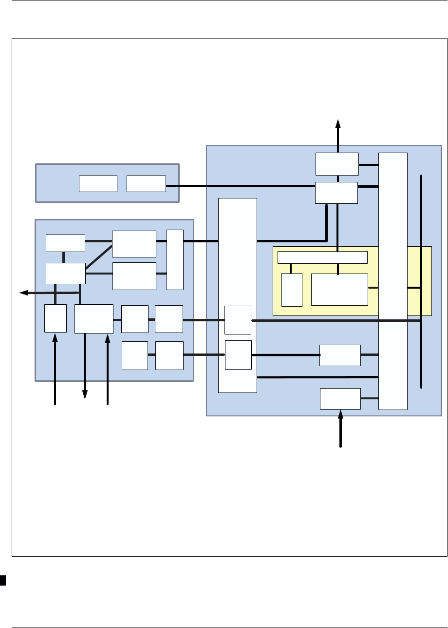
Software descrIptionNortel Networks Confidential 4–7
S8000/S8002/S8006 BTS Reference Manual
Ethernet
L3–RSL
L3–O&M–
AMNU
LAPDm
SPU
RX
L
A
P
D
BDT
L3–PCMI
L3–DSC
LAPD
ROT
L3–SYN
L3–ALCO
GTW
TIL
DRX (*)
BCF
BSC
L1–
O&M
L1–
ALCO
L2–O&M
L3–O&M–
CSWM
L1–O&M
N3–TX L3–
O&M L1–
O&M
L1–
BDT
Nota : (*) DRX ou e–DRX.
L3–TIL
Radio
signal
input
Radio
signal
output
PA
control
Alarms
FH
bus
Internal PCMs
External
PCMs
Figure 4–1 Software functions (with BCF)

Software descrIption Nortel Networks Confidential
4–8
PE/DCL/DD/0063
411–9001–063 Standard 12.07/EN September 2000 GSM/BSS V12
TIL
OS
KERNEL
ABIS
O&M
KERNEL
O&M
specific
Group of slave
managers
OS specific
(BSP)
CBCF
DRX (*)
Group of slave
equipment CPCMI RECAL
Note: (*) DRX or e–DRX.
Figure 4–2 Software functions (with CBCF)

Software descrIptionNortel Networks Confidential 4–9
S8000/S8002/S8006 BTS Reference Manual
L3 O&M AMNU
This software unit centralizes the operating and maintenance functions:
initialitization and monitoring of BISTs
connection with Abis
downloading and software marking
configuration
defense and alarms
tool functions
transmission of GSM TIME to BDT, and of O&M to TX
L3 RSL
This software unit represents the Radio Resource (RR) and the radio measurements
function (L1M) in the BTS:
radio link layer management
dedicated channel management
common channel management
TRX management
error handling
measurement collecting
measurement pre–processing (for power control by the BTS, and for call
clearing and handover decision for the BSC)
LAPDm
This software unit provides the LAPDm radio level 2 protocol with the mobile.
SPU
This software unit enables the level 1 radio communication with the mobile to
transmit and receive:
gateway between radio and terrestrial network (Abis) for the traffic channel
multiplexing and demultiplexing of the logical channels on physical channels
RX
This software unit provides the radioelectrical reception function.

Software descrIption Nortel Networks Confidential
4–10
PE/DCL/DD/0063
411–9001–063 Standard 12.07/EN September 2000 GSM/BSS V12
L3 TX
This software unit manages and monitors radio transmission. It is installed in each
DRX board. It sets the transmitter operation mode, defines the FH bus input from
which the TX should read data, and defines the transmission power to be used. It
also forwards TX alarms to the CSWM and controls the Power Amplifier (PA).
L1 BDT
This software unit extracts the GSM TIME carried on the PCMp (GSM TIME TS)
for the BDT unit.
LAPD
This software unit manages the LAPD link level 2 protocol on PCM between DRX
and BSC.
L1 O&M, L2 O&M
These software units manage the link level 1 & 2 protocol on private PCMs between
DRX and CSWM.
4.2.1.1 Defense
The DRX (or e–DRX) board carries out no defense actions by itself.
4.2.2 BCF software functions
The Base Common Functions unit (BCF) is located in the cabinet. It is downloaded
by the BSC, it provides the interface between the BTS and its Base Station
Controller (BSC). It also handles the following functions:
It sets the signaling channel and physical path concentration.
It generates and distributes the GSM time to all BTS units.
It monitors and detects all BTS alarms.
It correlates some BTS alarms in order to provide to the BSC a logical state of the
BTS, by using the event reporting procedure. The DRX is still monitored partly
by the BCF (TX) and partly by the DRX (AMNU/SPU).
It provides local protection of some BTS modules, by implementing redundant
equipment units.
Synchronization unit level 3 layer (L3–SYN)
This software unit is installed in each synchronization unit. It monitors
synchronization board switching, and sends a message to the CSWM whenever
switching occurs.

Software descrIptionNortel Networks Confidential 4–11
S8000/S8002/S8006 BTS Reference Manual
Alarm unit level 3 layer (L3–ALCO)
This software unit is installed in the ALCO board. It makes it possible to set the
board alarm loops, under CSWM control. It sends all alarm and control loop states
to the CSWM.
Dual PCM link unit level 3 layer (L3–PCMI)
This software is installed in each PCMI board. It makes it possible to configure the
board, and monitors the board and the two associated PCM link operations. It also
carries out signaling to the CSWM when a failure occurs.
Concentrator unit level 3 layer (L3–DSC)
This software unit is installed in each DSC board and enables board configuration;
It concentrates the signaling of several DRX (or e–DRX) units onto the BSC
signaling channel, and conversely separates BSC signaling and routes it towards the
DRX units.
L1 BDT
This level interfaces the GSM TIME bus with a dedicated TS of all private PCM
links.
ROT
This level formats into frames the character flow coming from ROT, and routes
these frames towards the OMC.
LAPD management (LAPD)
This software unit manages a LAPD link between the CSWM and the BSC through
the DSCs.
L3 O&M CSWM
The main functions of this layer are the following:
conversion between GSM entities and hardware entities
configuration of the internal PCM links
configuration of the FH bus
supervision of the different slave equipments (PCMI, DSC, TX, ALCO, SYNC,
GTW, switching matrix, O&M bus)
management of the duplex

Software descrIption Nortel Networks Confidential
4–12
PE/DCL/DD/0063
411–9001–063 Standard 12.07/EN September 2000 GSM/BSS V12
4.2.2.1 Defense
The BCF contains several defense mechanisms:
paired units operating in active/standby mode:
•two synchronization boards (SYNC)
•two gateway boards (GTW)
•two control and switching boards (CSWM). In order to provide switching in
warm duplex mode, the standby chain is updated in real time.
redundant units:
•one DSC board can be reserved for redundant use
•one PCM interface bord can be reserved for redundant use.
4.2.3 CBCF software functions
CBCF Software is based on a COAM software architecture, which is composed of
three main parts:
common software for various BTS products
•OS Kernel
•O&M Kernel
BTS–specific software dedicated to a BTS product
•OS–specific
•O&M–specific
slave managers
The COAM architecture is shown in Figure 4–3.
The CBCF software manages the following O&M functions:
PCM management
configuration and supervision management
software management
synchronization management
test management
duplex management

Software descrIptionNortel Networks Confidential 4–13
S8000/S8002/S8006 BTS Reference Manual
Layers 2
Layer 3 access
Layers 2
Layer 3 access
Software
management Abis management
Equipment
manager Connection
manager
Radio
resource
manager
Synchro
manager
Interlayer CBCF
Slave managers
DRX
manager CPCMI
manager RECAL
manager
S
c
h
e
d
u
l
e
r
D
u
p
l
e
x
M
a
n
a
g
e
r
O&M
kernel
CBCF
T
I
L
BSC
DRX (*)
equipment CPCMI
equipment RECAL
equipment
Note: (*) DRX or e–DRX.
Figure 4–3 COAM architecture on the CBCF

Software descrIption Nortel Networks Confidential
4–14
PE/DCL/DD/0063
411–9001–063 Standard 12.07/EN September 2000 GSM/BSS V12
4.2.3.1 PCM Management
This function selects one of the incoming PCMs for communication with the BSC.
It then routes PCM TSs to the appropriate equipment in the BTS as the BSC
requests. Other PCM TSs are routed toward another PCM to allow drop & insert
functionality.
This function also ensures LAPD concentration.
4.2.3.2 Configuration and supervision management
This function translates the OML A–bis model into a physical model to offer a
standardized configuration and supervision to the BSC. The CBCF acts as an A–bis
front end toward the BSC for configuration and supervision purposes. It is the only
link for configuration messages coming from the BSC. The CBCF uses the
CBCF/DRX protocol to drive any actions concerning the DRX
4.2.3.3 Software management
The CBCF performs software management for the BTS and provides the only link
for downloading messages from the BSC. When a RECAL or CPCMI board is
downloaded, the CBCF/Slave protocol is used.
4.2.3.4 Synchronization management
The CBCF builds the GSM time and provides it to the DRX via a TS or a private
PCM. External PCMs ensure long term stability.
4.2.3.5 Test Management
The CBCF coordinates all BTS tests. When an installation or maintenance action
affects a DRX, the DRX is driven by the CBCF using the CBCF/DRX Protocol.
4.2.3.6 Duplex Management
The COAM software manages a cold and hot duplex modes.

Software descrIptionNortel Networks Confidential 4–15
S8000/S8002/S8006 BTS Reference Manual
4.2.4 TIL software functions
TIL is an application running on a PC in the WINDOWS 95 environment. The TIL
application is connected to the BCF or CBCF through an ethernet connection.
The TIL is designed to do the following:
validate the BTS in the factory
install the BTS site
perform diagnostics of hardware problems
check equipment substitution
check the equipment extension within a cabinet
Ethernet
This unit is installed in the PC. It provides the level 1 and 2 communication layer.
Level 1 is a hardware driver. The level 2 protocol is an LAPD UI frame. TCP–IP
Protocol is used.
L3 TIL
This software unit manages all the boards of the BTS by establishment of a network
with all the GSM entities of the BTS. It integrates the factory and installation test
environment.
The TIL takes the following testing into consideration:
the conformity of the cabinet configuration
the validity of the data links
the external BTS PCM
the connectors in the cabinet for cabinet extensions

Software descrIption Nortel Networks Confidential
4–16
PE/DCL/DD/0063
411–9001–063 Standard 12.07/EN September 2000 GSM/BSS V12
PAGE INTENTIONALLY LEFT BLANK

Dimensioning rulesNortel Networks Confidential 5–1
S8000/S8002/S8006 BTS Reference Manual
5 DIMENSIONING RULES
5.1 Generalities on dimensioning
Base Transceiver Stations (BTS) have to be dimensioned on both the radio and Abis
interfaces.
The dimensions of the interface with the Base Station Controller (BSC) is calculated
on the basis of traffic handled on the Abis interface PCM links.
5.1.1 RADIO interface dimensions
The dimensions of the radio interface with Mobile Stations (MS) are calculated on
the basis of the number of Traffic Channels (TCH) needed to handle the traffic, the
number of SDCCH/8, BCCH channels and the control channel (RACH, PCH,
AGCH) dimensions.
5.1.1.1 Traffic (TCH), signaling (SDCCH/8) and broadcasting (BCCH) channels
Each transceiver (TRX) manages eight channels that can each support traffic
(TCH), signaling (SDCCH), broadcasting (BCCH) and control (RACH, PCH,
AGCH) channels.
The average occupation of a traffic channel is 100 seconds per call for
approximately 15 seconds of occupation of a signaling channel. In all cases a
broadcasting channel is reserved for use by BCCH frequency filling and control
channel support.
Depending on the position of cells in relation to the location area, the number of
SDCCH channels is liable to change:
The SDCCH channel payload in cells in outer location areas is increased by
location updating procedures.
The same dimensioning rules govern multi–cell sites since each cell operates
independently at radio level.
The number of TCH in a TDMA depends on the type of the TDMA:
M054E123

Dimensioning rules Nortel Networks Confidential
5–2
PE/DCL/DD/0063
411–9001–063 Standard 12.07/EN September 2000 GSM/BSS V12
Standard cell
TS0 TS1 TS2 TS3 à TS7
C:
combined TDMA for low traffic BCCH
+
SDCCH/4 TCH TCH TCH
c:
combined TDMA for low traffic BCCH
+
SDCCH/4
+
CBCH
TCH TCH TCH
B:
TDMA for standard traffic BCCH SDCCH/8 TCH TCH
b1:
TDMA for standard traffic BCCH SDCCH/8
+
CBCH TCH TCH
b2:
TDMA for standard traffic BCCH TCH TCH TCH
S:
Extension TDMA TCH SDCCH/8 TCH TCH
S1:
Extension TDMA (if DRX) TCH SDCCH/8 SDCCH/8 TCH
s:
Extension TDMA TCH SDCCH/8
+
CBCH TCH TCH
s1:
Extension TDMA (if DRX) TCH SDCCH/8
+
CBCH SDCCH/8 TCH
T:
Traffic TDMA TCH TCH TCH TCH

Dimensioning rulesNortel Networks Confidential 5–3
S8000/S8002/S8006 BTS Reference Manual
Extended cell
TS0 TS1, 3, 5, 7 TS2 TS4, 6
C_ext:
combined TDMA for low
traffic
BCCH
+
SDCCH/4 TCH TCH
c_ext:
combined TDMA for low
traffic
BCCH
+
SDCCH/4
+
CBCH
TCH TCH
B_ext:
TDMA for standard traffic BCCH SDCCH/8 TCH
b1_ext:
TDMA for standard traffic BCCH SDCCH/8
+
CBCH TCH
b2_ext:
TDMA for standard traffic BCCH TCH TCH
S_ext:
Extension TDMA TCH SDCCH/8 TCH
s_ext:
Extension TDMA TCH SDCCH/8
+
CBCH TCH
T_ext:
Traffic TDMA TCH TCH TCH
Extended ccch
TS0 TS1, 3, 5, 7 TS2 TS4 TS6
b3:
TDMA for
standard traffic
BCCH TCH CCCH TCH TCH
b4:
TDMA for
standard traffic BCCH TCH CCCH CCCH TCH
b5:
TDMA for
standard traffic
BCCH TCH CCCH CCCH CCCH

Dimensioning rules Nortel Networks Confidential
5–4
PE/DCL/DD/0063
411–9001–063 Standard 12.07/EN September 2000 GSM/BSS V12
5.1.1.2 AGCH + PCH common channel
The channel payload is largely induced by “paging” messages used for locating the
MS with a view to setting up a call. The remaining load is taken up by resource
allocation messages issued by the AGCH for location updating purposes, paging
responses and calls emitted by MS onto the fixed network.
The rule is to systematically reserve at least one access grant channel (AGCH).
By dimensioning paging channels a single common channel is occupied even when
the needs of high capacity base station, wide location area and paging repeat
message have to be covered .
5.1.2 Abis Interface dimensioning
Time slots at 64 kbit/s are needed to convey user traffic along the TCH between the
BSC and BTS. Each cell must continuously transmit the BCCH frequency.
The traffic channel supports user traffic and signaling channels used for traffic
management functions and operation/maintenance purposes. TCH channels are
concentrated on radio sites and conveyed onto the Abis interface. Different
configurations are possible on Abis interface. Each of them, is shown on
Figure 5–1.
5.1.2.1 Drop and insert techniques
Two types of connections allow drop and insert technique: chain connection and
loop connection.
Chain connection
The same external PCM link enables the connections between BSC and several Base
Transceiver Station (BTS) equipments.
Each BTS uses a set of 64 kbit/s time slots.
Loop connection
For a chain connection, if one link between two BTSs fails, all the BTSs will be lost.
However, to correct this disadvantage, the last BTS in the chain is looped back to
the BSC using a PCM link. It is then possible to reconfigure the BTS units.
This drop and insert capability does not require any additional or specific
equipment, or any specific software. When a BTS is being configured, the 64 kbit/s
time slots are reserved for its usage. All other time slots stay in the “dropped”
position.
The drop and insert techniques obey to the following rules:

Dimensioning rulesNortel Networks Confidential 5–5
S8000/S8002/S8006 BTS Reference Manual
Wiring rule: a PCM link enters via an even DTI board (2. n) and leaves via an odd
DTI board (2.n + 1).
TEI rule: from the first BTS to the last BTS chained, the TEI number assigned to
each BTS must be increased by 1.
Number of TCHs and secondary LAPD:
2 x number of TRXs
number of PCMs connected to the BTS + secondary LAPD
without taking into account redundant PCM links. In the case of a loop links
configuration, the number of PCM links connected to the BTS is equal to 1.
In order to avoid LAPD crossing, the wiring and TEI rules must be applied.
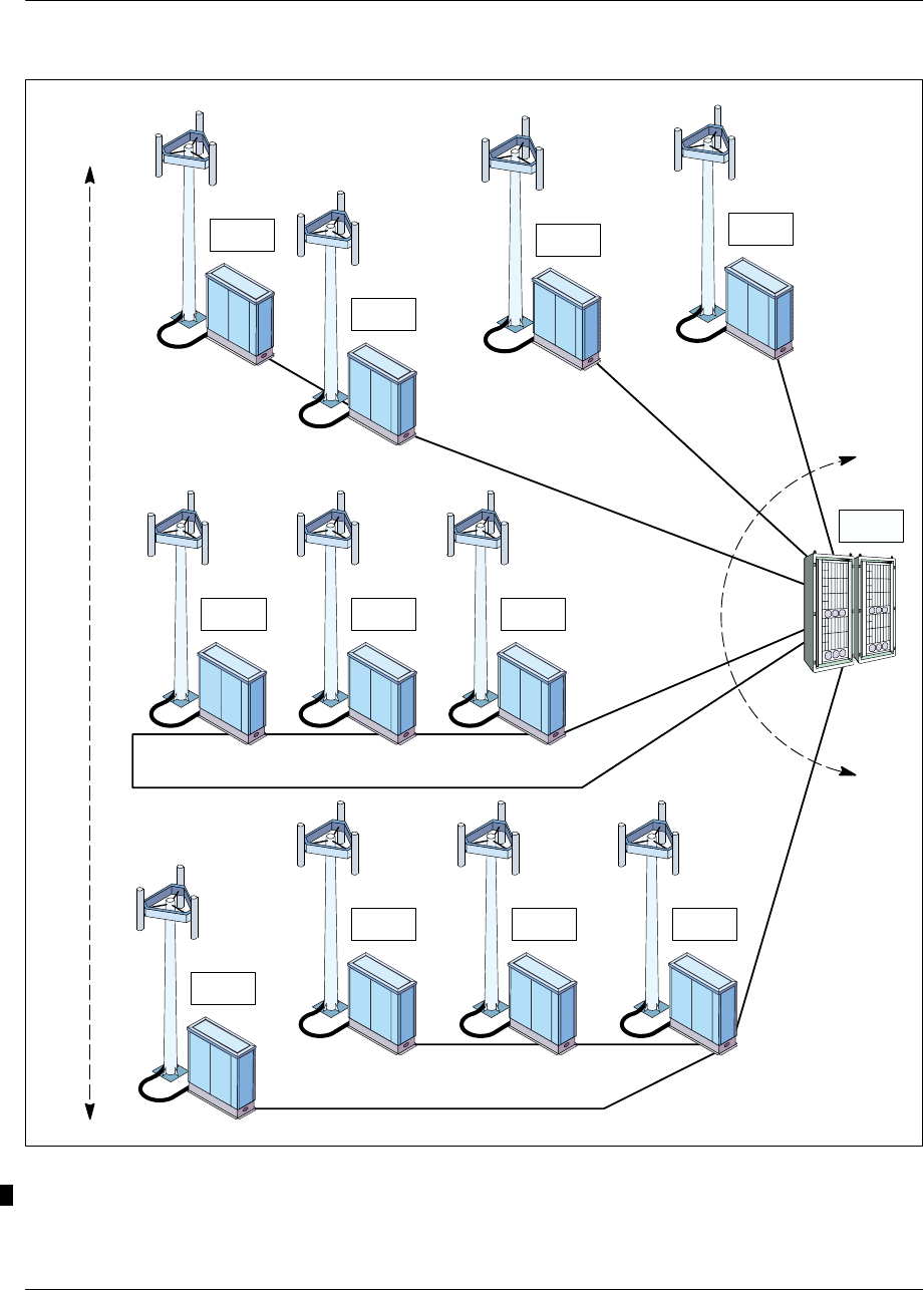
Dimensioning rules Nortel Networks Confidential
5–6
PE/DCL/DD/0063
411–9001–063 Standard 12.07/EN September 2000 GSM/BSS V12
Star
connection
Chain
connection Abis
Interface
BTS BTS
BTS
BTS
BTS BTS
BTS
BTSBTS
BTS
BSC
BTS
Loop connection
Radio
Interface
Hub and Spoke connection
Figure 5–1 Types of BTS connections

Dimensioning rulesNortel Networks Confidential 5–7
S8000/S8002/S8006 BTS Reference Manual
5.2 Dimensioning of the BTS
5.2.1 Configurations
The maximum configurations are as follows:
omnidirectional with one cabinet: 1O1 to 1O8
omnidirectional with two cabinets: 2O16
sectorial: up to a 3S888
hexasectorial: up to 666_222 (dualband configuration)

Dimensioning rules Nortel Networks Confidential
5–8
PE/DCL/DD/0063
411–9001–063 Standard 12.07/EN September 2000 GSM/BSS V12
5.2.2 Dimensioning of radio and Abis interfaces
Table 5–1 determines the number of traffic channels (TCH) required per cell, with
an assumption of 25 mE/subscriber at peak time. The jam rate is 2% for the TCHs
and 10–3 for SDCCH.
Config. Standard cell Extended cell LAPD
channels Voice
time slot PCM No.
Erlangs TCH Erlangs TCH
O1 2.27 6 0.6 3 1 2 1
O2 8.20 14 2.23 6 1 4 1
O4 21.0 29 8.20 14 1 8 1
O8 48.7 59 21 29 1 16 1
S11 4.54 12 1.2 6 1 4 1
S44 42 58 16.4 28 1 16 1
S111 6.81 18 1.8 9 1 6 1
S222 24.6 42 6.69 18 1 12 1
S233 36.2 56 17.6 26 1 16 1
S224 37.4 57 12.7 26 1 16 1
S333 42 63 23.1 30 3 18 1
S444 63 87 24.6 42 3 24 1 (E1) or 2 (T1)
S555 81.9 108 34.5 54 3 30 2
S666 104 132 42 63 3 36 2
S777 126 153 52.5 75 3 42 2
S888 146 177 63 87 3 48 2 (E1) or 3 (T1)
111_111 13.62 36 – – 1 12 1
222_222 49.2 84 – – 2 24 1 (E1) or 2 (T1)
444_222 87.6 129 – – 3 36 2
444–444 126 174 – – 3 48 2 (E1) or 3 (T1)
555_333 123.9 171 – – 3 48 2
666_222 128.7 174 – – 3 48 2
Blockage rate: 2%, with full–speed TCU
With measurement pre–processing: 8 DRXs (or e–DRXs) / LAPD
Table 5–1 Dimensioning of radio and Abis interfaces

Dimensioning rulesNortel Networks Confidential 5–9
S8000/S8002/S8006 BTS Reference Manual
5.2.3 Dimensioning of DSC board (with BCF)
5.2.3.1 Design of DSC boards
The following table gives the number of DSC boards required according to the
number of cells and the number of concentrated signaling links (without
redundancy).
Cell 1 LAPD 2 LAPD 3 LAPD
11 DSC – –
21 DSC 2 DSC –
31 DSC 2 DSC 3 DSC
41 DSC 2 DSC 3 DSC
51 DSC 2 DSC 3 DSC
61 DSC 2 DSC 3 DSC
Table 5–2 Board dimensioning
If at a given time, the number of DSCs available is less than the number given in
this table, the entire site is lost until the number of DSCs is again correct. It is
therefore strongly recommended to have a redundant DSC board.
The number of TEI that can be handled by one LAPD link is limited to 8.
Two cells cannot share the same LAPD unless the whole site is carried by the
primary LAPD, except in case of an hexadecimal site.
TEI of the same cell must have the same LAPD number (if a cell has less than eight
TEIs), two TEIs of different cells can also have the same concentrated channel.
There must be one DSC board per LAPD time slot: 1 DSC board can handle only
one LAPD and vice versa one LAPD must be associated with a single board.
5.3 Configurations
Table 5–3 presents the possible configurations for the S8000 Indoor and
S8000 Outdoor for each coupling system. The configurations indicated in the
table below are highest configurations. They are not always available within the
three frequency bands. This table is given for refrence only.
Note that the number of converters in a cabinet can be depopulated according the
number of DRXs (or e–DRXs) in the cabinet.

Dimensioning rules Nortel Networks Confidential
5–10
PE/DCL/DD/0063
411–9001–063 Standard 12.07/EN September 2000 GSM/BSS V12
Coupling Frequency band
Coupling
system Configuration S8000I BTS S8000O BTS S8002 BTS S8006 BTS
D1O1 to 1S222 GSM 900,
GSM 1800
R–GSM,
GSM 900,
GSM 1800
GSM 1900,
R–GSM
2S111_111 to
2S222_222 Dual band
900/1800 Dual band
900/1800
O2 R–GSM
D + CC8 2O16 to 3S888 GSM 1800
with CBCF
module
H2D 1O1_O1 to 1O4_O4 Dual band
900/1800 Dual band
900/1800
1O1 to 3S888 * GSM 900,
GSM 1800 GSM 900,
GSM 1800,
GSM 1900
3S111_111 to
3S444_444 Dual band
900/1800 Dual band
900/1800
S222, S42, S24, S33 GSM 1800
H4D 1O1 to 3S888 GSM 900,
GSM 1800 GSM 900,
GSM 1800
GSM 1900
6S16–16–16 GSM 900, 6S16–16–16 GSM 900,
GSM 1800
D + H2D ** 3S111_111 to
3S444_222 Dual band
900 /1800 Dual band
900 /1800
2D+2TxF 1O1 to 2S44 GSM 900,
GSM 1800,
GSM 1900
GSM 900,
GSM 1800,
GSM 1900
H2D+H4D
2H2D+H4D
2D+2H2D
1O2 to 3S888
1O2 to 3S888
1O2 to 3S666
GSM 900,
GSM 1800 GSM 900,
GSM 1800,
GSM 1900
* Four antennas or two cross–polar antennas are required.
** With BSS restrictions.
Note: The following values apply for all table entries:
PA = 30 W
Rx Splitter = Splitter 1*4 + LNA
Receive sensitivity = –110 dBm guaranteed (If diversity and frequency hopping are considered,
the receive sensitivity is –115 dBm guaranteed.)
Table 5–3 Various configurations with each coupling system

Wireless Service Provider Solutions
S8000/S8002/S8006 BTS Reference Manual
Copyright 1996–2000 Nortel Networks, All Rights Reserved
NORTEL NETWORKS CONFIDENTIAL:
The information contained in this document is the property of Nortel
Networks. Except as specifically authorized in writing by Nortel
Networks, the holder of this document shall keep the information
contained herein confidential and shall protect same in whole or in part
from disclosure and dissemination to third parties and use for evaluation,
operation and maintenance purposes only.
You may not reproduce, represent, or download through any means, the
information contained herein in any way or in any form without prior
written consent of Nortel Networks.
The following are trademarks of Nortel Networks: *NORTEL
NETWORKS, the NORTEL NETWORKS corporate logo, the NORTEL
Globemark, UNIFIED NETWORKS, S8000.
GSM is a trademark of France Telecom.
All other brand and product names are trademarks or registred
trademarks of their respective holders.
Publication Reference
PE/DCL/DD/0063 411–9001–063
12.07/EN
September 2000
Printed in France
For more information, please contact:
For all countries, except USA:
Documentation Department
1, Place des Frères Montgolfier
GUYANCOURT
78928 YVELINES CEDEX 9
FRANCE
Email : gsmntp@nortelnetworks.com
Fax : (33) (1) 39–44–50–29
In the USA:
2221 Lakeside Boulevard
Richardson TX 75082
USA
Tel: 1–800–4 NORTEL
1–800–466–7838 or (972) 684–5935
Internet Address:
http://www.nortelnetworks.com