Avaya 585 215 871 User Manual To The Ae6c76e4 2fa4 4469 9613 B2bc2b5ac3ab
User Manual: Avaya 585-215-871 to the manual
Open the PDF directly: View PDF ![]() .
.
Page Count: 214 [warning: Documents this large are best viewed by clicking the View PDF Link!]
- Avaya Call Management System
- Sun Ultra 5 Computer
- Hardware Installation, Maintenance, and Troubleshooting
- Contents
- Preface
- Introduction
- Installation
- Overview
- Preparing for installation
- Unpacking and inventorying the equipment
- Setting up power
- Peripheral connectivity
- Parts list
- Connecting the monitor and keyboard
- Connecting the remote console modem
- Connecting to external interfaces
- Turning the system on and verifying POST
- Identifying installed PCI cards
- Setting the remote console modem options
- Turning the system over for provisioning
- Maintenance
- Overview
- Computer layout
- ESD precautions
- Maintaining PCI cards
- Maintaining disk drives
- Overview
- Disk drive compatibility with CMS loads
- Prerequisites
- Required references
- Replacing the primary internal EIDE boot disk drive
- Adding or replacing the internal EIDE data disk drive
- Adding or replacing external SCSI disk drives
- Setting up the disk drives
- Partitioning disk drives
- Administering data disk drives
- Replacing the CD-ROM drive
- Maintaining tape drives
- Adding memory and replacing the CPU
- Troubleshooting
- Overview
- References
- Using the remote console
- Tools
- Troubleshooting disk drives and CD-ROM drives
- Troubleshooting tape drives
- Recovery procedures
- Appendix A: Factory hardware installation
- Glossary
- Index

Avaya™ Call Management System (CMS)
Sun® Ultra™ 5 Computer
Hardware Installation, Maintenance, and
Troubleshooting
585-215-871
Issue 3.3
February 2003
Compas ID 79853

© 2003 Avaya Inc.
All Rights Reserved.
Notice
Every effort was made to ensure that the information in this document
was complete and accurate at the time of printing. However, information
is subject to change.
Preventing Toll Fraud
“Toll fraud” is the unauthorized use of your telecommunications system
by an unauthorized party (for example, a person who is not a corporate
employee, agent, subcontractor, or working on your company's behalf).
Be aware that there may be a risk of toll fraud associated with your
system and that, if toll fraud occurs, it can result in substantial additional
charges for your telecommunications services.
Avaya Fraud Intervention
If you suspect that you are being victimized by toll fraud and you need
technical assistance or support, call Technical Service Center Toll Fraud
Intervention Hotline at +1-800-643-2353 for the United States and
Canada. For additional support telephone numbers, see the Avaya Web
site:
http://www.avaya.com
Select Support, then select Escalation Lists. This Web site includes
telephone numbers for escalation within the United States. For escalation
telephone numbers outside the United States, select Global Escalation
List.
Providing Telecommunications Security
Telecommunications security (of voice, data, and/or video
communications) is the prevention of any type of intrusion to (that is,
either unauthorized or malicious access to or use of) your company's
telecommunications equipment by some party.
Your company's “telecommunications equipment” includes both this
Avaya product and any other voice/data/video equipment that could be
accessed via this Avaya product (that is, “networked equipment”).
An “outside party” is anyone who is not a corporate employee, agent,
subcontractor, or working on your company's behalf. Whereas, a
“malicious party” is anyone (including someone who may be otherwise
authorized) who accesses your telecommunications equipment with
either malicious or mischievous intent.
Such intrusions may be either to/through synchronous (time-multiplexed
and/or circuit-based) or asynchronous (character-, message-, or packet-
based) equipment or interfaces for reasons of:
• Utilization (of capabilities special to the accessed equipment)
• Theft (such as, of intellectual property, financial assets, or
toll-facility access)
• Eavesdropping (privacy invasions to humans)
• Mischief (troubling, but apparently innocuous, tampering)
• Harm (such as harmful tampering, data loss or alteration,
regardless of motive or intent)
Be aware that there may be a risk of unauthorized intrusions associated
with your system and/or its networked equipment. Also realize that, if
such an intrusion should occur, it could result in a variety of losses to your
company (including but not limited to, human/data privacy, intellectual
property, material assets, financial resources, labor costs, and/or legal
costs).
Your Responsibility for Your Company’s Telecommunications
Security
The final responsibility for securing both this system and its networked
equipment rests with you - an Avaya customer's system administrator,
your telecommunications peers, and your managers. Base the fulfillment
of your responsibility on acquired knowledge and resources from a
variety of sources including but not limited to:
• Installation documents
• System administration documents
• Security documents
• Hardware-/software-based security tools
• Shared information between you and your peers
• Telecommunications security experts
To prevent intrusions to your telecommunications equipment, you and
your peers should carefully program and configure:
• your Avaya-provided telecommunications systems and their
interfaces
• your Avaya-provided software applications, as well as their
underlying hardware/software platforms and interfaces
• any other equipment networked to your Avaya products.
Trademarks
AUDIX and CentreVu are registered trademarks of Avaya Inc.
Avaya and INTUITY are trademarks of Avaya, Inc.
CentreCOM is a registered trademark of Allied Telesis.
Comsphere is a registered trademark of Paradyne Inc.
Enterprise, Sun, Solaris, SunVTS, and Network Terminal Server are
trademarks or registered trademarks of Sun Microsystems, Inc.
Micro Annex is a registered trademark of Nortel Networks, Inc.
Paradyne is a trademark of Paradyne Inc.
Phillips is a registered trademark of the Phillips Screw Company.
Sportster and U.S. Robotics are registered trademarks of U.S. Robotics,
Inc.
UNIX is a registered trademark in the United States and other countries,
licensed exclusively through X/Open Company Limited.
All other product names mentioned herein are the trademarks of their
respective owners.
Avaya Support
Avaya provides a telephone number for you to use to report problems or
to ask questions about your contact center. The support telephone
number is 1-800-242-2121 in the United States. For additional support
telephone numbers, see the Avaya Web site:
http://www.avaya.com
Select Support, then select Escalation Lists. This Web site includes
telephone numbers for escalation within the United States. For escalation
telephone numbers outside the United States, select Global Escalation
List.
Acknowledgment
This document was written by the CRM Information Development group.

Issue 3.3 February 2003 3
Contents 3
Preface . . . . . . . . . . . . . . . . . . . . . . . . . . . . . . . . . . . . . . . . 9
Overview . . . . . . . . . . . . . . . . . . . . . . . . . . . . . . . . . . . . . . . 9
Reasons for reissue . . . . . . . . . . . . . . . . . . . . . . . . . . . . . . . . . . 9
Organization . . . . . . . . . . . . . . . . . . . . . . . . . . . . . . . . . . . . . . 11
Related documents. . . . . . . . . . . . . . . . . . . . . . . . . . . . . . . . . . . 12
CMS software documents . . . . . . . . . . . . . . . . . . . . . . . . . . . . . . . 12
Upgrade documents. . . . . . . . . . . . . . . . . . . . . . . . . . . . . . . . . . 13
Hardware documents . . . . . . . . . . . . . . . . . . . . . . . . . . . . . . . . . 15
Switch documents. . . . . . . . . . . . . . . . . . . . . . . . . . . . . . . . . . . 15
Administration documents . . . . . . . . . . . . . . . . . . . . . . . . . . . . . . . 16
Other documents . . . . . . . . . . . . . . . . . . . . . . . . . . . . . . . . . . . 16
Documentation Web sites . . . . . . . . . . . . . . . . . . . . . . . . . . . . . . . . 17
Introduction . . . . . . . . . . . . . . . . . . . . . . . . . . . . . . . . . . . . . . . . 19
Overview . . . . . . . . . . . . . . . . . . . . . . . . . . . . . . . . . . . . . . . 19
Support . . . . . . . . . . . . . . . . . . . . . . . . . . . . . . . . . . . . . . . . 20
Frequently asked questions (FAQs) . . . . . . . . . . . . . . . . . . . . . . . . . . 20
Customer support for the United States. . . . . . . . . . . . . . . . . . . . . . . . . 20
Technician support for the United States . . . . . . . . . . . . . . . . . . . . . . . . 20
Customer and technician support outside the United States . . . . . . . . . . . . . . . 20
Installation . . . . . . . . . . . . . . . . . . . . . . . . . . . . . . . . . . . . . . . . 21
Overview . . . . . . . . . . . . . . . . . . . . . . . . . . . . . . . . . . . . . . . 21
Preparing for installation . . . . . . . . . . . . . . . . . . . . . . . . . . . . . . . . 22
Safety precautions . . . . . . . . . . . . . . . . . . . . . . . . . . . . . . . . . . 22
System precautions . . . . . . . . . . . . . . . . . . . . . . . . . . . . . . . . . . 23
Required tools . . . . . . . . . . . . . . . . . . . . . . . . . . . . . . . . . . . . 23
Electrical specifications . . . . . . . . . . . . . . . . . . . . . . . . . . . . . . . . 24
Physical specifications . . . . . . . . . . . . . . . . . . . . . . . . . . . . . . . . 25
Environmental specifications. . . . . . . . . . . . . . . . . . . . . . . . . . . . . . 25
Miscellaneous specifications. . . . . . . . . . . . . . . . . . . . . . . . . . . . . . 26
Unpacking and inventorying the equipment . . . . . . . . . . . . . . . . . . . . . . . 27
Parts list . . . . . . . . . . . . . . . . . . . . . . . . . . . . . . . . . . . . . . . 28
Determining the computer model. . . . . . . . . . . . . . . . . . . . . . . . . . . . 29
Features . . . . . . . . . . . . . . . . . . . . . . . . . . . . . . . . . . . . . . 29
Physical labeling . . . . . . . . . . . . . . . . . . . . . . . . . . . . . . . . . . 30
Avaya Call Management System
Sun Ultra 5 Computer
Hardware Installation, Maintenance, and Troubleshooting
Contents

Contents
4 Avaya CMS Sun Ultra 5 Computer Hardware Installation, Maintenance, and Troubleshooting
Software check. . . . . . . . . . . . . . . . . . . . . . . . . . . . . . . . . . . 30
Computer layout . . . . . . . . . . . . . . . . . . . . . . . . . . . . . . . . . . . 31
Front Panel . . . . . . . . . . . . . . . . . . . . . . . . . . . . . . . . . . . . 31
Rear Panel (with SunSwift® card) . . . . . . . . . . . . . . . . . . . . . . . . . . 31
Rear Panel (with UltraSCSI card) . . . . . . . . . . . . . . . . . . . . . . . . . . 32
Setting up power . . . . . . . . . . . . . . . . . . . . . . . . . . . . . . . . . . . . 33
Peripheral connectivity . . . . . . . . . . . . . . . . . . . . . . . . . . . . . . . . . 34
Parts list . . . . . . . . . . . . . . . . . . . . . . . . . . . . . . . . . . . . . . . . 36
Connecting the monitor and keyboard . . . . . . . . . . . . . . . . . . . . . . . . . . 37
Connecting the remote console modem . . . . . . . . . . . . . . . . . . . . . . . . . 38
Connecting to external interfaces . . . . . . . . . . . . . . . . . . . . . . . . . . . . 39
Connecting the switch link . . . . . . . . . . . . . . . . . . . . . . . . . . . . . . . 39
Connecting the serial port expander box . . . . . . . . . . . . . . . . . . . . . . . . 40
Connecting external SCSI devices . . . . . . . . . . . . . . . . . . . . . . . . . . . 41
SunSwift connections. . . . . . . . . . . . . . . . . . . . . . . . . . . . . . . . 41
UltraSCSI connections . . . . . . . . . . . . . . . . . . . . . . . . . . . . . . . 43
Turning the system on and verifying POST . . . . . . . . . . . . . . . . . . . . . . . 46
Identifying installed PCI cards. . . . . . . . . . . . . . . . . . . . . . . . . . . . . . 49
Setting the remote console modem options . . . . . . . . . . . . . . . . . . . . . . . 50
Sportster 33.6 faxmodem . . . . . . . . . . . . . . . . . . . . . . . . . . . . . . . 50
Paradyne Comsphere 3910 modem . . . . . . . . . . . . . . . . . . . . . . . . . . 52
Recommended options . . . . . . . . . . . . . . . . . . . . . . . . . . . . . . . 52
Option buttons . . . . . . . . . . . . . . . . . . . . . . . . . . . . . . . . . . . 52
Setting the options . . . . . . . . . . . . . . . . . . . . . . . . . . . . . . . . . 53
Turning the system over for provisioning. . . . . . . . . . . . . . . . . . . . . . . . . 57
Maintenance . . . . . . . . . . . . . . . . . . . . . . . . . . . . . . . . . . . . . . . . 59
Overview . . . . . . . . . . . . . . . . . . . . . . . . . . . . . . . . . . . . . . . 59
Computer layout . . . . . . . . . . . . . . . . . . . . . . . . . . . . . . . . . . . . 60
Front Panel. . . . . . . . . . . . . . . . . . . . . . . . . . . . . . . . . . . . . . 60
Rear Panel (with SunSwift card) . . . . . . . . . . . . . . . . . . . . . . . . . . . . 61
Rear Panel (with UltraSCSI card) . . . . . . . . . . . . . . . . . . . . . . . . . . . 62
ESD precautions . . . . . . . . . . . . . . . . . . . . . . . . . . . . . . . . . . . . 63
Maintaining PCI cards . . . . . . . . . . . . . . . . . . . . . . . . . . . . . . . . . 64
Overview . . . . . . . . . . . . . . . . . . . . . . . . . . . . . . . . . . . . . . . 64
Required references . . . . . . . . . . . . . . . . . . . . . . . . . . . . . . . . . 64
Identifying free card slots . . . . . . . . . . . . . . . . . . . . . . . . . . . . . . . 64
PCI card configuration. . . . . . . . . . . . . . . . . . . . . . . . . . . . . . . . . 65
Installing or removing PCI cards . . . . . . . . . . . . . . . . . . . . . . . . . . . . 66
Replacing an UltraSCSI card with a SunSwift card . . . . . . . . . . . . . . . . . . . 68
Prerequisites. . . . . . . . . . . . . . . . . . . . . . . . . . . . . . . . . . . . 68
Procedure . . . . . . . . . . . . . . . . . . . . . . . . . . . . . . . . . . . . . 68
SAI/P cards. . . . . . . . . . . . . . . . . . . . . . . . . . . . . . . . . . . . . . 71
Identifying device entry names for ports on an SAI/P card . . . . . . . . . . . . . . 71
Adding, moving, or removing an SAI/P card . . . . . . . . . . . . . . . . . . . . . 71
Removing SAI/P drivers and utilities . . . . . . . . . . . . . . . . . . . . . . . . . 75
Installing HSI/P cards . . . . . . . . . . . . . . . . . . . . . . . . . . . . . . . . . 77

Contents
Issue 3.3 February 2003 5
Replacing an HSI/P card . . . . . . . . . . . . . . . . . . . . . . . . . . . . . . 78
Installing the first HSI/P card or a pair of HSI/P cards . . . . . . . . . . . . . . . . . 78
Installing HSI/P software and patches . . . . . . . . . . . . . . . . . . . . . . . . 79
Setting up the switch link for each ACD . . . . . . . . . . . . . . . . . . . . . . . 80
Adding a second HSI/P card . . . . . . . . . . . . . . . . . . . . . . . . . . . . 81
Maintaining disk drives . . . . . . . . . . . . . . . . . . . . . . . . . . . . . . . . . 83
Overview . . . . . . . . . . . . . . . . . . . . . . . . . . . . . . . . . . . . . . . 83
Disk drive compatibility with CMS loads . . . . . . . . . . . . . . . . . . . . . . . . 83
Prerequisites . . . . . . . . . . . . . . . . . . . . . . . . . . . . . . . . . . . . . 83
Required references . . . . . . . . . . . . . . . . . . . . . . . . . . . . . . . . . 84
Replacing the primary internal EIDE boot disk drive . . . . . . . . . . . . . . . . . . . 85
Opening the computer . . . . . . . . . . . . . . . . . . . . . . . . . . . . . . . 85
Removing the primary internal boot disk drive . . . . . . . . . . . . . . . . . . . . 87
Installing the new primary internal disk drive . . . . . . . . . . . . . . . . . . . . . 89
Closing the computer . . . . . . . . . . . . . . . . . . . . . . . . . . . . . . . . 91
Turning on the system . . . . . . . . . . . . . . . . . . . . . . . . . . . . . . . 92
Adding or replacing the internal EIDE data disk drive . . . . . . . . . . . . . . . . . . 93
Unpacking the disk drive . . . . . . . . . . . . . . . . . . . . . . . . . . . . . . 93
Opening the computer . . . . . . . . . . . . . . . . . . . . . . . . . . . . . . . 94
Removing the secondary internal disk drive . . . . . . . . . . . . . . . . . . . . . 96
Removing the diskette drive. . . . . . . . . . . . . . . . . . . . . . . . . . . . . 97
Installing new cabling . . . . . . . . . . . . . . . . . . . . . . . . . . . . . . . . 98
Installing the secondary disk drive . . . . . . . . . . . . . . . . . . . . . . . . . . 99
Closing the computer . . . . . . . . . . . . . . . . . . . . . . . . . . . . . . . . 100
Turning on the system . . . . . . . . . . . . . . . . . . . . . . . . . . . . . . . 101
Adding or replacing external SCSI disk drives . . . . . . . . . . . . . . . . . . . . . 102
Adding or replacing a disk drive . . . . . . . . . . . . . . . . . . . . . . . . . . . 102
Turning on the system . . . . . . . . . . . . . . . . . . . . . . . . . . . . . . . 108
Setting up the disk drives . . . . . . . . . . . . . . . . . . . . . . . . . . . . . . . 110
Partitioning disk drives . . . . . . . . . . . . . . . . . . . . . . . . . . . . . . . . 111
R3V9 and later . . . . . . . . . . . . . . . . . . . . . . . . . . . . . . . . . . . 111
R3V8 and earlier . . . . . . . . . . . . . . . . . . . . . . . . . . . . . . . . . . 111
Disk partition values . . . . . . . . . . . . . . . . . . . . . . . . . . . . . . . . 111
Partitioning and formatting a disk . . . . . . . . . . . . . . . . . . . . . . . . . . 117
Administering data disk drives . . . . . . . . . . . . . . . . . . . . . . . . . . . . . 121
Administering new data disks, R3V9 and later . . . . . . . . . . . . . . . . . . . . 121
Administering replacement data disks, R3V9 and later . . . . . . . . . . . . . . . . 122
Administering a new data disk, R3V8 and earlier . . . . . . . . . . . . . . . . . . . 122
Administering a replacement data disk, R3V8 and earlier . . . . . . . . . . . . . . . 126
Replacing the CD-ROM drive . . . . . . . . . . . . . . . . . . . . . . . . . . . . . . 130
Opening the computer. . . . . . . . . . . . . . . . . . . . . . . . . . . . . . . . . 130
Removing and replacing the CD-ROM drive . . . . . . . . . . . . . . . . . . . . . . 132
Closing the computer . . . . . . . . . . . . . . . . . . . . . . . . . . . . . . . . . 133
Turning on the system. . . . . . . . . . . . . . . . . . . . . . . . . . . . . . . . . 134
Maintaining tape drives . . . . . . . . . . . . . . . . . . . . . . . . . . . . . . . . . 135
Overview . . . . . . . . . . . . . . . . . . . . . . . . . . . . . . . . . . . . . . . 135
Required references . . . . . . . . . . . . . . . . . . . . . . . . . . . . . . . . . 135
Ordering tapes . . . . . . . . . . . . . . . . . . . . . . . . . . . . . . . . . . . . 135
Cleaning the tape drive . . . . . . . . . . . . . . . . . . . . . . . . . . . . . . . . 136

Contents
6 Avaya CMS Sun Ultra 5 Computer Hardware Installation, Maintenance, and Troubleshooting
DDS4 tape drive . . . . . . . . . . . . . . . . . . . . . . . . . . . . . . . . . . 136
SLR5 tape drive . . . . . . . . . . . . . . . . . . . . . . . . . . . . . . . . . . 137
XL/XS/DX tape drive . . . . . . . . . . . . . . . . . . . . . . . . . . . . . . . . 137
Adding, removing, or replacing tape drives . . . . . . . . . . . . . . . . . . . . . . . 138
Adding or replacing a tape drive. . . . . . . . . . . . . . . . . . . . . . . . . . . 138
Removing a tape drive . . . . . . . . . . . . . . . . . . . . . . . . . . . . . . . 145
Adding memory and replacing the CPU . . . . . . . . . . . . . . . . . . . . . . . . . 147
Overview . . . . . . . . . . . . . . . . . . . . . . . . . . . . . . . . . . . . . . . 147
Installing memory . . . . . . . . . . . . . . . . . . . . . . . . . . . . . . . . . . . 147
Checking the current memory size . . . . . . . . . . . . . . . . . . . . . . . . . 147
Opening the computer . . . . . . . . . . . . . . . . . . . . . . . . . . . . . . . 148
Adding the DIMMs . . . . . . . . . . . . . . . . . . . . . . . . . . . . . . . . . 150
Closing the computer . . . . . . . . . . . . . . . . . . . . . . . . . . . . . . . . 151
Checking the new memory size . . . . . . . . . . . . . . . . . . . . . . . . . . . 151
Adding swap space (R3V6 or earlier only) . . . . . . . . . . . . . . . . . . . . . . 152
Troubleshooting . . . . . . . . . . . . . . . . . . . . . . . . . . . . . . . . . . . . . . 153
Overview . . . . . . . . . . . . . . . . . . . . . . . . . . . . . . . . . . . . . . . 153
References . . . . . . . . . . . . . . . . . . . . . . . . . . . . . . . . . . . . . . 153
Using the remote console. . . . . . . . . . . . . . . . . . . . . . . . . . . . . . . . 154
Overview . . . . . . . . . . . . . . . . . . . . . . . . . . . . . . . . . . . . . . . 154
Redirecting the console using Solaris . . . . . . . . . . . . . . . . . . . . . . . . . 154
Redirecting the local console to the remote console . . . . . . . . . . . . . . . . . 154
Redirecting the remote console back to the local console . . . . . . . . . . . . . . . 156
Redirecting the console using OpenBoot mode . . . . . . . . . . . . . . . . . . . . . 157
Redirecting the local console to the remote console . . . . . . . . . . . . . . . . . 157
Redirecting the remote console back to the local console . . . . . . . . . . . . . . . 158
Tools . . . . . . . . . . . . . . . . . . . . . . . . . . . . . . . . . . . . . . . . . 161
Using the prtdiag command . . . . . . . . . . . . . . . . . . . . . . . . . . . . . . 162
System messages . . . . . . . . . . . . . . . . . . . . . . . . . . . . . . . . . . 163
OpenBoot PROM firmware tests . . . . . . . . . . . . . . . . . . . . . . . . . . . . 164
Using the OpenBoot PROM tests . . . . . . . . . . . . . . . . . . . . . . . . . . 164
Test descriptions . . . . . . . . . . . . . . . . . . . . . . . . . . . . . . . . . . 165
Probing IDE devices . . . . . . . . . . . . . . . . . . . . . . . . . . . . . . . . 166
Probing SCSI devices . . . . . . . . . . . . . . . . . . . . . . . . . . . . . . . 167
OpenBoot diagnostic tests. . . . . . . . . . . . . . . . . . . . . . . . . . . . . . . 169
POST diagnostic messages . . . . . . . . . . . . . . . . . . . . . . . . . . . . . . 172
Memory failure . . . . . . . . . . . . . . . . . . . . . . . . . . . . . . . . . . . 172
OpenBoot initialization commands . . . . . . . . . . . . . . . . . . . . . . . . . . . 173
Diagnosing LED patterns . . . . . . . . . . . . . . . . . . . . . . . . . . . . . . . 174
Keyboard LED patterns . . . . . . . . . . . . . . . . . . . . . . . . . . . . . . . 174
Tape drive LED status patterns . . . . . . . . . . . . . . . . . . . . . . . . . . . 174
Sun Validation Test Suite (VTS) . . . . . . . . . . . . . . . . . . . . . . . . . . . . 176
Prerequisites. . . . . . . . . . . . . . . . . . . . . . . . . . . . . . . . . . . . 176
Using SunVTS . . . . . . . . . . . . . . . . . . . . . . . . . . . . . . . . . . . 176
Troubleshooting disk drives and CD-ROM drives. . . . . . . . . . . . . . . . . . . . . 177
Troubleshooting tape drives. . . . . . . . . . . . . . . . . . . . . . . . . . . . . . . 179
Overview . . . . . . . . . . . . . . . . . . . . . . . . . . . . . . . . . . . . . . . 179

Contents
Issue 3.3 February 2003 7
Checking tape status . . . . . . . . . . . . . . . . . . . . . . . . . . . . . . . . . 179
Rebuilding tape device drivers . . . . . . . . . . . . . . . . . . . . . . . . . . . . . 181
Recovery procedures . . . . . . . . . . . . . . . . . . . . . . . . . . . . . . . . . . 182
Preserving data after a system failure . . . . . . . . . . . . . . . . . . . . . . . . . 182
Loss of power. . . . . . . . . . . . . . . . . . . . . . . . . . . . . . . . . . . . . 182
Keyboard becomes unplugged. . . . . . . . . . . . . . . . . . . . . . . . . . . . . 183
Probe command warnings . . . . . . . . . . . . . . . . . . . . . . . . . . . . . . . 184
Reseating HSI/P cards . . . . . . . . . . . . . . . . . . . . . . . . . . . . . . . . 185
Remote console port problems. . . . . . . . . . . . . . . . . . . . . . . . . . . . . 186
Appendix A: Factory hardware installation . . . . . . . . . . . . . . . . . . . . . . . 189
Overview . . . . . . . . . . . . . . . . . . . . . . . . . . . . . . . . . . . . . . . 189
Preparing for factory hardware installation . . . . . . . . . . . . . . . . . . . . . . . . 190
Computer layout . . . . . . . . . . . . . . . . . . . . . . . . . . . . . . . . . . . 190
Front Panel . . . . . . . . . . . . . . . . . . . . . . . . . . . . . . . . . . . . 190
Rear Panel (with SunSwift card). . . . . . . . . . . . . . . . . . . . . . . . . . . 191
Rear Panel (with UltraSCSI card) . . . . . . . . . . . . . . . . . . . . . . . . . . 191
ESD precautions . . . . . . . . . . . . . . . . . . . . . . . . . . . . . . . . . . . 192
Installing an optional second internal hard drive . . . . . . . . . . . . . . . . . . . . . 193
Unpacking the disk drive . . . . . . . . . . . . . . . . . . . . . . . . . . . . . . 193
Opening the computer . . . . . . . . . . . . . . . . . . . . . . . . . . . . . . . 194
Removing the secondary internal disk drive . . . . . . . . . . . . . . . . . . . . . 196
Removing the diskette drive. . . . . . . . . . . . . . . . . . . . . . . . . . . . . 197
Installing new cabling . . . . . . . . . . . . . . . . . . . . . . . . . . . . . . . . 198
Installing the secondary disk drive . . . . . . . . . . . . . . . . . . . . . . . . . . 199
Closing the computer . . . . . . . . . . . . . . . . . . . . . . . . . . . . . . . . 200
Installing memory. . . . . . . . . . . . . . . . . . . . . . . . . . . . . . . . . . . . 201
Overview. . . . . . . . . . . . . . . . . . . . . . . . . . . . . . . . . . . . . . 201
Opening the computer . . . . . . . . . . . . . . . . . . . . . . . . . . . . . . . 201
Adding the memory modules . . . . . . . . . . . . . . . . . . . . . . . . . . . . 203
Closing the computer . . . . . . . . . . . . . . . . . . . . . . . . . . . . . . . . 204
Installing PCI cards. . . . . . . . . . . . . . . . . . . . . . . . . . . . . . . . . . . 205
PCI card configuration. . . . . . . . . . . . . . . . . . . . . . . . . . . . . . . . . 205
Installing PCI cards . . . . . . . . . . . . . . . . . . . . . . . . . . . . . . . . . . 206
Glossary . . . . . . . . . . . . . . . . . . . . . . . . . . . . . . . . . . . . . . . . 209
Index . . . . . . . . . . . . . . . . . . . . . . . . . . . . . . . . . . . . . . . . 211

Contents
8 Avaya CMS Sun Ultra 5 Computer Hardware Installation, Maintenance, and Troubleshooting

Issue 3.3 February 2003 9
Preface
Overview
Avaya™ Call Management System (CMS) Sun® Ultra™ 5 Computer Hardware
Installation, Maintenance, and Troubleshooting, 585-215-871, is written for technicians
who install and maintain call center applications such as Avaya CMS.
Reasons for reissue
Issue 3.3 of this document was issued for the following changes:
●To add partitioning information for the 36-GB external SCSI disk drive (see Partitioning
disk drives on page 111).
●To update the tape ordering procedures (see Ordering tapes on page 135).
●To make general wording and format corrections to the document.
Issue 3.2 of this document was issued for the following changes:
●To update the disk drive maintenance procedures, including new disk partitioning for
CMS R3V11 (see Maintaining disk drives on page 83).
●To make general wording and format corrections to the document.
Issue 3.1 of this document was issued for the following changes:
●To add partitioning information for a new 4-GB EIDE disk drive (see Disk partition
values, R3V8 and earlier data disks on page 115).
●To remove information about installing network hubs and Network Terminal Servers
(NTS). This information is now contained in Avaya CMS Terminals, Printers, and
Modems, 585-215-874.
●To remove references to the product name CentreVu®.
●To make general wording corrections to the document.

Preface
10 Avaya CMS Sun Ultra 5 Computer Hardware Installation, Maintenance, and Troubleshooting
Issue 3.0 of this document was issued for the following changes:
●To update the disk drive maintenance procedures for CMS R3V9 (see Maintaining disk
drives on page 83).
●To add information about the 18-GB external SCSI disk drive (see Disk partition
values on page 111).
●To make general wording corrections to the document.
Issue 2.2 of this document was issued for the following changes:
●To change references from Lucent Technologies to Avaya.
●To add information about the 20-GB disk drive (see Overview on page 19, Determining
the computer model on page 29, and Disk partition values on page 111).
●To add information about disk configurations (see Overview on page 19).
●To add information about the 400 MHz CPU (see Determining the computer model on
page 29).
●To add information about the new autosensing power supply (see Setting up power on
page 33).
●To update the HSI card installation procedures (see Installing HSI/P cards on page 77).
●To update the disk drive maintenance procedures (see Maintaining disk drives on
page 83).
●To update the remote console procedure (see Using the remote console on page 154).
●To add information about system messages (see System messages on page 163).
●To add tape drive LED status patterns (see Tape drive LED status patterns on
page 174).
●To remove information about specific UPS models. A UPS is still required, but must be
provided locally.
●To make the organization of this book consistent with other Sun hardware installation
books.
●To make general wording corrections to the document.
Issue 2.1 of this document was issued for the following changes:
●To add information about the new Digital Data Storage (DDS) model DDS4, 4-millimeter
tape drive. This tape drive replaces the SLR5 Quarter-Inch-Cartridge (QIC) tape drive.
●To move hardware maintenance and troubleshooting information to this document. This
information was previously found in CentreVu Call Management System R3V8
Hardware Maintenance and Troubleshooting, 585-215-873.
●To make general wording corrections to the document.

Organization
Issue 3.3 February 2003 11
Organization
This document is organized as follows:
●Introduction – Provides an overview of the Ultra 5 computer and helpline information.
●Installation – Describes how to assemble the Ultra 5 computer, connect external
devices, and power-up the computer.
●Maintenance – Describes how to maintain the Ultra 5 computer.
●Troubleshooting – Describes how to troubleshoot the Ultra 5 computer.
●Factory hardware installation – Describes how to configure the Ultra 5 to factory
specifications.
●Glossary
●Index
Preface
12 Avaya CMS Sun Ultra 5 Computer Hardware Installation, Maintenance, and Troubleshooting
Related documents
Related documents lists sources for information related to contact center products and
features. Not all documents are supported for all CMS releases or equipment.
To order Avaya documentation, call the Avaya Publications Center at 1-800-457-1235
(United States and Canada) or +1-207-866-6701 (outside the United States and Canada).
CMS software documents
Document title Document
number
Installing software on a CMS computer
Avaya CMS R3V11 Software Installation, Maintenance, and Troubleshooting Guide 585-215-115
CentreVu Call Management System Release 3 Version 9 Software Installation,
Maintenance, and Troubleshooting 585-215-956
Setting up a disk-mirrored system
Avaya CMS R3V11 Software Installation, Maintenance, and Troubleshooting Guide 585-215-115
CentreVu Call Management System Release 3 Version 9 Software Installation,
Maintenance, and Troubleshooting 585-215-956
Related documents
Issue 3.3 February 2003 13
Upgrade documents
There are several upgrade paths supported with CMS. There is a document designed to
support each upgrade. Note that none of the following upgrade documents are available
from the publications center.
●Base load upgrades
Use a base load upgrade when upgrading CMS to the latest load of the same version
(for example, R3V9 ak.g to R3V9 al.k). A specific set of instructions is written for the
upgrade and is shipped to the customer site with the CMS software CD-ROM as part of
a Quality Protection Plan Change Notice (QPPCN).
●Platform upgrades and data migration
Use a platform upgrade when upgrading to a new hardware platform (for example,
upgrading from a SPARCserver 5 to an Enterprise 3500). The new hardware platform
is shipped from the factory with the latest CMS load. Therefore, as part of the upgrade
you will have the latest CMS load (for example, R3V9 to R3V11 or the latest load of the
same CMS version). For R3V11, a specific set of instructions is written for the upgrade
and is shipped to the customer site with the new hardware.
Document title
Avaya CMS R3V11 Base Load Upgrades
CentreVu Call Management System Release 3 Version 9 Base Load Upgrade Procedures
Document title
Avaya Call Management System Release 3 Version 11 Platform Upgrade and Data Migration
CentreVu Call Management System Release 3 Version 9 Platform Upgrade and Data Migration
Instructions
Preface
14 Avaya CMS Sun Ultra 5 Computer Hardware Installation, Maintenance, and Troubleshooting
●Avaya Call Management System Upgrade Express (CUE)
Use CUE in the following conditions:
— CMS is being upgraded from an earlier version (for example, R3V5u or R3V6) to the
latest version (for example, R3V9 or R3V11).
— The hardware platform is not changing.
A specific set of upgrade instructions is written for the upgrade and is shipped to the
customer site with the CUE kit.
Document title
Avaya Call Management System Release 3 Version 11 Sun Blade 100 Workstation CMS Upgrade
Express
Avaya Call Management System Release 3 Version 11 Sun Blade 100 Workstation Mirrored System
CMS Upgrade Express
Avaya Call Management System Release 3 Version 11 Sun Ultra 5 Computer CMS Upgrade Express
Avaya Call Management System Release 3 Version 11 Sun Enterprise 3000 Computer CMS
Upgrade Express
Avaya Call Management System Release 3 Version 11 Sun Enterprise 3000 Computer Mirrored
System CMS Upgrade Express
Avaya Call Management System Release 3 Version 11 Sun Enterprise 3500 Computer CMS
Upgrade Express
Avaya Call Management System Release 3 Version 11 Sun Enterprise 3500 Computer Mirrored
System CMS Upgrade Express
CentreVu Call Management System Release 3 Version 9 Sun Ultra 5 Computer CVUE Instructions
CentreVu Call Management System Release 3 Version 9 Sun Enterprise 3000 Computer CVUE
Instructions
CentreVu Call Management System Release 3 Version 9 Sun Enterprise 3000 Computer Mirrored
System CVUE Instructions
CentreVu Call Management System Release 3 Version 9 Sun Enterprise 3500 Computer CVUE
Instructions
CentreVu Call Management System Release 3 Version 9 Sun Enterprise 3500 Computer Mirrored
System CVUE Instructions
Related documents
Issue 3.3 February 2003 15
Hardware documents
Switch documents
Document title Document
number
Avaya Call Management System Sun Fire V880 Computer Hardware Installation,
Maintenance, and Troubleshooting 585-215-116
Avaya Call Management System Sun Fire V880 Computer Connectivity Diagram 585-215-612
Avaya Call Management System Sun Blade 100/150 Computer Hardware
Installation, Maintenance, and Troubleshooting 585-310-783
Call Management System Sun Blade 100/150 Computer Connectivity Diagram 585-310-782
Avaya Call Management System Sun Enterprise 3500 Computer Hardware
Installation, Maintenance, and Troubleshooting 585-215-873
Call Management System Sun Enterprise 3500 Computer Connectivity Diagram 585-215-877
Avaya Call Management System Sun Ultra 5 Computer Hardware Installation,
Maintenance, and Troubleshooting 585-215-871
Call Management System Sun Ultra 5 Computer Connectivity Diagram 585-215-872
Avaya Call Management System Sun Enterprise 3000 and SPARCserver
Computers Hardware Maintenance and Troubleshooting 585-214-016
Avaya Call Management System Terminals, Printers, and Modems 585-215-874
Document title Document
number
Avaya Call Management System Switch Connections, Administration, and
Troubleshooting 585-215-876
Preface
16 Avaya CMS Sun Ultra 5 Computer Hardware Installation, Maintenance, and Troubleshooting
Administration documents
Other documents
Document title Document
number
Avaya Call Management System Release 3 Version 11 Administration 585-215-515
CentreVu Call Management System Release 3 Version 9 Administration 585-214-015
Document title Document
number
Avaya CMS Open Database Connectivity 585-780-701
Avaya CMS R3V11 LAN Backup User Guide 585-215-715
Avaya CMS R3V11 External Call History Interface 585-780-700
CentreVu CMS Release 3 Version 9 External Call History Interface 585-215-952
Avaya CMS Custom Reports 585-215-822
Avaya CMS Forecast 585-215-825
Avaya Visual Vectors Version 11 Installation and Getting Started 585-210-706
Avaya Visual Vectors Version 11 User Guide 585-210-709
Avaya Visual Vectors Version 9 Installation and Getting Started 585-210-947
Avaya Visual Vectors Version 9 User Guide 585-210-944

Documentation Web sites
Issue 3.3 February 2003 17
Documentation Web sites
For product documentation for all Avaya products and related documentation, go to
http://www.avayadocs.com.
!Important:
!Important:
Important: Additional information about new software or hardware updates will be
contained in future issues of this book. New issues of this book will be
placed on the Web site when available.
Use the following web sites to view related support documentation:
●Information about Avaya products and service
http://www.avaya.com
●Sun hardware documentation
http://docs.sun.com
●Okidata printer documentation
http://www.okidata.com
●Informix documentation
http://www.informix.com
●Tivoli Storage Manager documentation
http://tivoli.com

Preface
18 Avaya CMS Sun Ultra 5 Computer Hardware Installation, Maintenance, and Troubleshooting

Issue 3.3 February 2003 19
Introduction
Overview
The Sun Ultra 5 computer provides a hardware platform that supports call center software
applications, and is designed to do the following:
●Increase performance with the SPARC-V9 64-bit RISC architecture (includes a 400
MHz clock and a 256 KB internal cache in the current model; older models have
different clock speeds).
●Enhance system availability by using error-correcting memory. This memory protects
the system and data from single-bit soft errors that can occur.
●Provide expandable performance and capabilities with a balanced architecture (all
elements of the system, CPU, memory, I/O, and graphics work at full speed).
●Include a minimum internal disk storage space of 20 GB.
— A 20-GB EIDE primary disk drive is the current standard on Ultra 5 computers
delivered from the factory. Newer models may have larger primary disk drives. Older
models may have an 8.3-GB or a 4.3-GB primary disk drive.
— An optional 20-GB EIDE secondary disk drive may be ordered. This drive can be
added as the primary or secondary internal disk drive for older models of the Ultra 5
to increase disk capacity. Older models may have a 9.1-GB secondary disk drive.
●Accommodate up to four external small computer system interface (SCSI) disk drives
and two SCSI tape drives.
●Allow for cost-effective upgrades to disk storage and memory.

Introduction
20 Avaya CMS Sun Ultra 5 Computer Hardware Installation, Maintenance, and Troubleshooting
Support
If you need assistance with a problem, use the support information and help lines
presented below.
Frequently asked questions (FAQs)
For solutions to common problems, customers and Avaya technicians can access
technical support FAQs at:
http://www.avaya.com
Select Support > Call Center/CRM and select the product for which you need support.
Please check this information before you call in a trouble ticket. Doing so could save you
time and money.
Customer support for the United States
Customers can report problems and generate trouble tickets by calling:
1-800-242-2121
The customer is prompted to identify the type of problem (that is, Automatic Call
Distribution, hardware, or Avaya CMS) and is then connected to the appropriate service
organization.
Technician support for the United States
Avaya technicians can receive help by calling:
1-800-248-1234
Customer and technician support outside the United States
For customer and technician support outside the United States, see the Avaya Web site:
http://www.avaya.com
Select Support > Escalation Lists US and International. For escalation telephone
numbers outside the United States, select Global Escalation List.
Issue 3.3 February 2003 21
Installation
Overview
This chapter describes how to install the Ultra 5 computer and related peripheral
equipment. Use the following table to check off each required procedure after completion.
Procedure Completed
Preparing for installation on page 22
Unpacking and inventorying the equipment on page 27
Setting up power on page 33
Peripheral connectivity on page 34
Connecting the monitor and keyboard on page 37
Connecting the remote console modem on page 38
Connecting to external interfaces:
— Connecting the switch link on page 39
— Connecting the serial port expander box on page 40
— Connecting external SCSI devices on page 41
Turning the system on and verifying POST on page 46
Identifying installed PCI cards on page 49
Setting the remote console modem options on page 50
Turning the system over for provisioning on page 57
Installation
22 Avaya CMS Sun Ultra 5 Computer Hardware Installation, Maintenance, and Troubleshooting
Preparing for installation
This section contains information that will help you prepare for the Ultra 5 computer
installation.
Safety precautions
For your protection, observe the following safety precautions when setting up your
equipment:
●Follow all cautions, warnings, and instructions that are marked on the equipment.
●Never push objects of any kind through openings in the equipment. They could touch
dangerous voltage points or short out components that could result in fire or electric
shock.
●Refer servicing of equipment to qualified personnel.
●To protect both yourself and the equipment, observe the following precautions.
Item Problem Precaution
Wrist or
foot strap ESD Wear a conductive wrist strap or foot
strap when handling printed circuit
boards.
Cover
panels System
damage and
overheating
Reinstall all cabinet cover panels after
you perform any service work on the
system.
Board slot
filler
panels
System
damage and
overheating
Make sure that a filler panel is installed
on all empty board slots.

Preparing for installation
Issue 3.3 February 2003 23
System precautions
Ensure that the voltage and frequency of the power outlet used matches the electrical
rating labels on the equipment.
Wear antistatic wrist straps when handling any magnetic storage devices, and printed
circuit boards.
The Ultra 5 computer uses nominal input voltages of 100-240 V AC at 50-60 Hz. The
Ultra 5 should be powered by a non-switched, dedicated, 15-amp circuit. Sun products are
designed to work with single-phase power systems having a grounded neutral conductor
under safety precautions. To reduce the risk of electrical shock, do not plug Sun products
into another type of power source. Contact your facilities manager or qualified electrician if
you are unsure what type of power is supplied to your building.
A UPS provides a temporary electrical supply to a computer for several minutes,
depending on the number of components connected to the UPS. For a CMS computer,
a 2KVA minimum UPS is required for all installations. See your UPS documentation to
determine the projected amount of backup battery time for your model. If the system is
without power for longer than the backup time, the system may shut down improperly, and
the customer could lose data.
Each of the following items requires a separate power cord:
●Ultra 5 computer
●External peripherals
●Monitor
!WARNING:
WARNING: DO NOT make mechanical or electrical modifications to the computer. Sun
Microsystems is not responsible for regulatory compliance of modified
computers.
Required tools
You need the following tools to do the installation:
●Phillips® #2 screwdriver
●Needle-nose pliers
●ESD grounding wrist strap
●Antistatic mat
Installation
24 Avaya CMS Sun Ultra 5 Computer Hardware Installation, Maintenance, and Troubleshooting
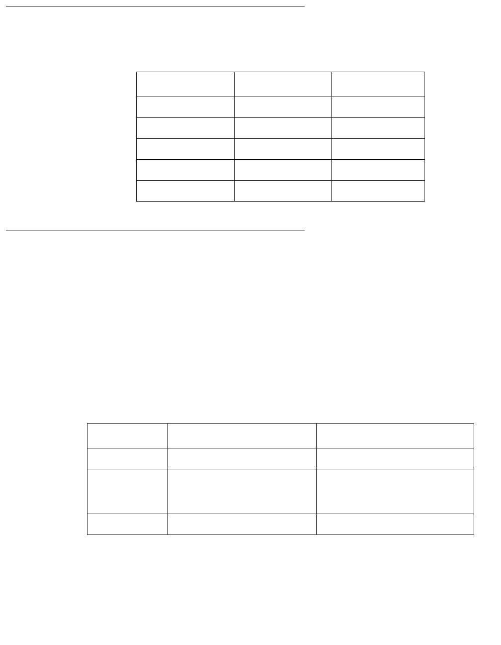
Electrical specifications
Note:
Note: For power integrity, an Uninterruptible Power Supply (UPS) is recommended
for all installations.
Parameter Value
Input current
- Voltage range
- Current, frequency range
- Current, maximum (120 V)
100-240 V AC, autosensing
(newer systems)
100 to 125 or 200 to 240 V AC, switch
selectable (older systems)
50-60 Hz
6A@120 V
Input power rating (total
continuous power) 200 W
Volt-ampere rating 300 VA
BTU rating 967 BTU
Wall plug type
- United States
- Non-United States NEMA 5-15P
Power cords must be obtained locally
CPU plug type IEC 320
Preparing for installation
Issue 3.3 February 2003 25
Physical specifications
Environmental specifications
For the most reliable system operation:
●The room must have sufficient air conditioning capacity to support the cooling needs of
the entire system.
●The air conditioning system must have controls that prevent excessive temperature
changes.
Follow the guidelines in the table below for temperature, humidity, and altitude limits for
units in operation and for units that are not in operation (that is, units that are in transit or in
storage).
Parameter English value Metric value
Height 4.4 inches 11.2 centimeters
Width 17.1 inches 43.6 centimeters
Depth 16.9 inches 43.0 centimeters
Weight 40 pounds 18 kilograms
Power cord 6.0 feet 1.8 meters
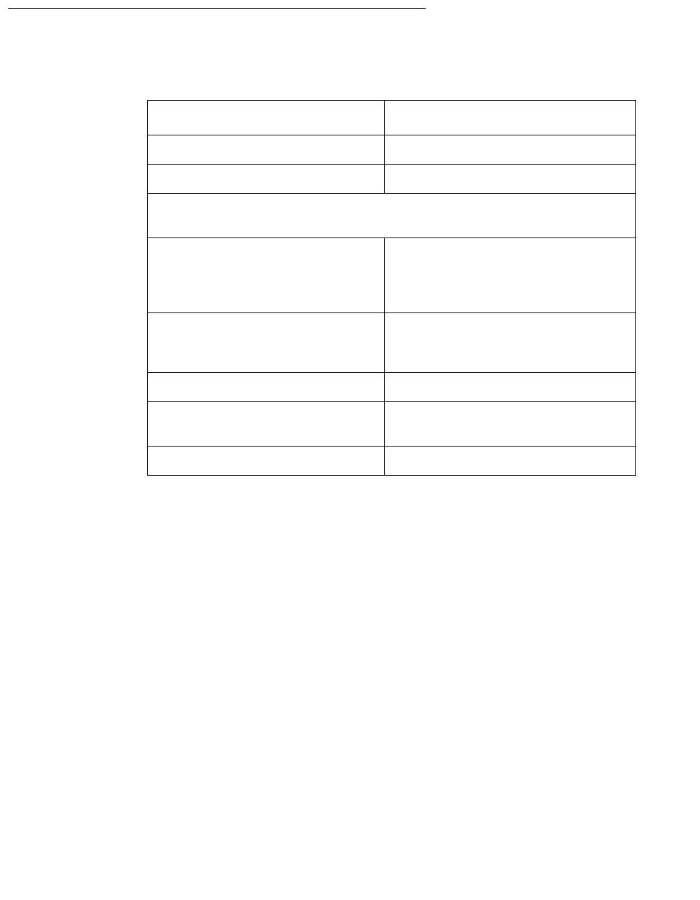
Parameter Operating Nonoperating
Temperature 41°F to 95°F (5°C to 35°C) -4°F to 140°F (-20°C to 60°C)
Humidity
(max) 20% to 80% RH
noncondensing
27°C max wb
93% RH
Altitude (max) 10,000 feet (3 kilometers) 40,000 feet (12 kilometers)
Installation
26 Avaya CMS Sun Ultra 5 Computer Hardware Installation, Maintenance, and Troubleshooting
Miscellaneous specifications
Parameter Value
Operating acoustic noise 5.2 decibels
Idling acoustic noise 5.1 decibels
Declared noise emissions in accordance with ISO 9296, measured
at 23°C.
Safety UL 1950, CSA C22.2 No. 950,
TUV EN 60950, CB Scheme with
Nordic deviations, EMKO-TSE
(74-SEC) 203, ZH1/618
RFI/EMI FCC Class B, DOC Class B, VCCI
Class 2, EN 5502 Class B,
EN 61000-3-2
Immunity EN 50082-1
X-ray DHHS 21 Subchapter J; PTB
German X-ray Decree
Power Management Energy Star Compliant

Unpacking and inventorying the equipment
Issue 3.3 February 2003 27
Unpacking and inventorying the equipment
!WARNING:
WARNING: Never move the computer when the power is on. Excessive movement can
cause catastrophic disk drive failure. Always power the system OFF before
moving the computer.
!WARNING:
WARNING: Always wear an electrostatic discharge (ESD) strap when handling internal
components.
Note:
Note: Always have up-to-date system backups before turning the computer off and
moving the computer.
Unpack the computer and associated peripheral equipment. Compare the contents of the
carton to the shipping inventory list to verify that all equipment was delivered.
Inspect all shipping cartons for evidence of physical damage. If a shipping carton is
damaged, request that the carrier representative be present before the carton is opened.
In the United States, contact the Services Support Organization (SSO) if any computer
parts are defective on arrival. Contact Avaya customer service if any computer parts are
missing.
Outside of the United States, contact your Avaya representative or distributor if any
computer parts are missing or defective.

Installation
28 Avaya CMS Sun Ultra 5 Computer Hardware Installation, Maintenance, and Troubleshooting
Parts list
Verify that you have the following components of the Ultra 5 computer:
●Ultra 5 unit (including installed cards) and power cord
●Monitor and power cord
●Monitor cable
●Keyboard and cable
●Mouse and cable
●DDS4, 4-millimeter cartridge tapes (older systems will have QIC tapes)
— One blank tape for backups
— One tape that contains the factory configuration CMSADM filesystem backup
— One tape drive cleaning cartridge
In addition, other external components, disk drives and tape drives, may be part of the
order. Verify that all expected parts have been delivered.

Unpacking and inventorying the equipment
Issue 3.3 February 2003 29
Determining the computer model
This book is written for several different models of the Ultra 5 computer. The differences
between the models are few. This section describes how you can tell what model you
have.
Features
Each of the different models have distinctive features that will also assist you in
determining what model you have.
●Series 1
— 270 MHz CPU
— 4.2-GB internal boot disk (4500 RPM)
— 24X CD-ROM
— 8-bit graphics
●Series 2
— 270 MHz CPU
— 4.2-GB internal boot disk (5400 RPM)
— 32X CD-ROM
— 24-bit graphics
●Series 3
— 360 MHz CPU
— 8.4-GB internal boot disk
— 32X CD-ROM
— 24-bit graphics
— 50ns RAM
— DDS4 external tape drive on newer models
— autosensing power supply on newer models
●Series 3, Model 400
— 400 MHz CPU
— 20-GB internal boot disk
— DDS4 external tape drive on all models
— autosensing power supply on all models

Installation
30 Avaya CMS Sun Ultra 5 Computer Hardware Installation, Maintenance, and Troubleshooting
Physical labeling
Near the left-front corner of the computer, there is a label that has the serial number and
other markings from the Sun factory. The models are marked as such:
●Series 1 – No special marking, just a serial number
●Series 2 – PGX24, plus the serial number
●Series 3 – Series 3, plus the serial number
●Series 3, Model 400 – BCD, Series 3, plus the serial number
Software check
Once the computer is operational, you can log in as root and enter the following command
to identify the computer model:
prtconf -vp | grep SUNW,3
●Series 1 – model: SUNW,3.11
●Series 2 – model: SUNW,3.15
●Series 3 – model: SUNW,3.19
●Series 3, Model 400 – model: SUNW,3.25
Unpacking and inventorying the equipment
Issue 3.3 February 2003 31
Computer layout
Familiarize yourself with the layout of the computer.
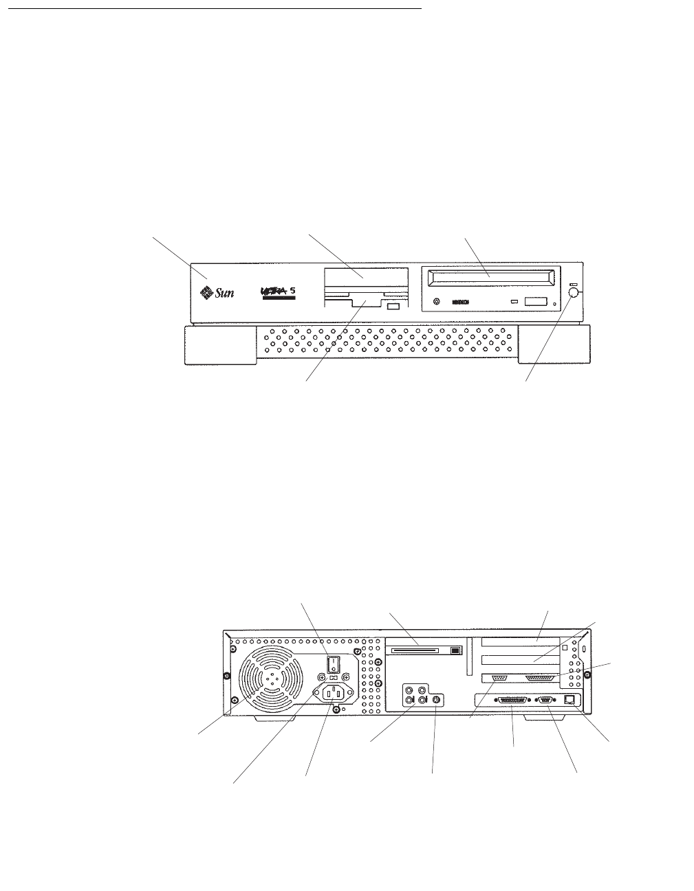
Front Panel
This figure shows the front panel of the Ultra 5. The diskette drive is not available if the
optional second internal hard drive has been installed.
Rear Panel (with SunSwift® card)
This figure shows the rear panel when you have a SunSwift card, which is usually installed
in PCI slot 2. The SunSwift card has one 68-pin SCSI connector and one ethernet RJ45
connector. Other PCI cards may be installed in slots 1 and 3.
System
unit
Diskette drive or second
internal hard drive
Standby
switch
CD-ROM
drive
3.5-inch bracket
(spare)
u5_front.cdr
Power
switch
SunSwift
card in
PCI slot 2
PCI
slot 3 PCI
slot 1
Parallel
printer
connector
Twisted-pair
ethernet
connector
VGA
connector
Serial
port A
Serial
port B
Keyboard
connector
Audio
connectors
Power cord
receptacle
Voltage selector
switch (older
models only)
Power
supply fan
u5_back_sunswift.cdr
Installation
32 Avaya CMS Sun Ultra 5 Computer Hardware Installation, Maintenance, and Troubleshooting
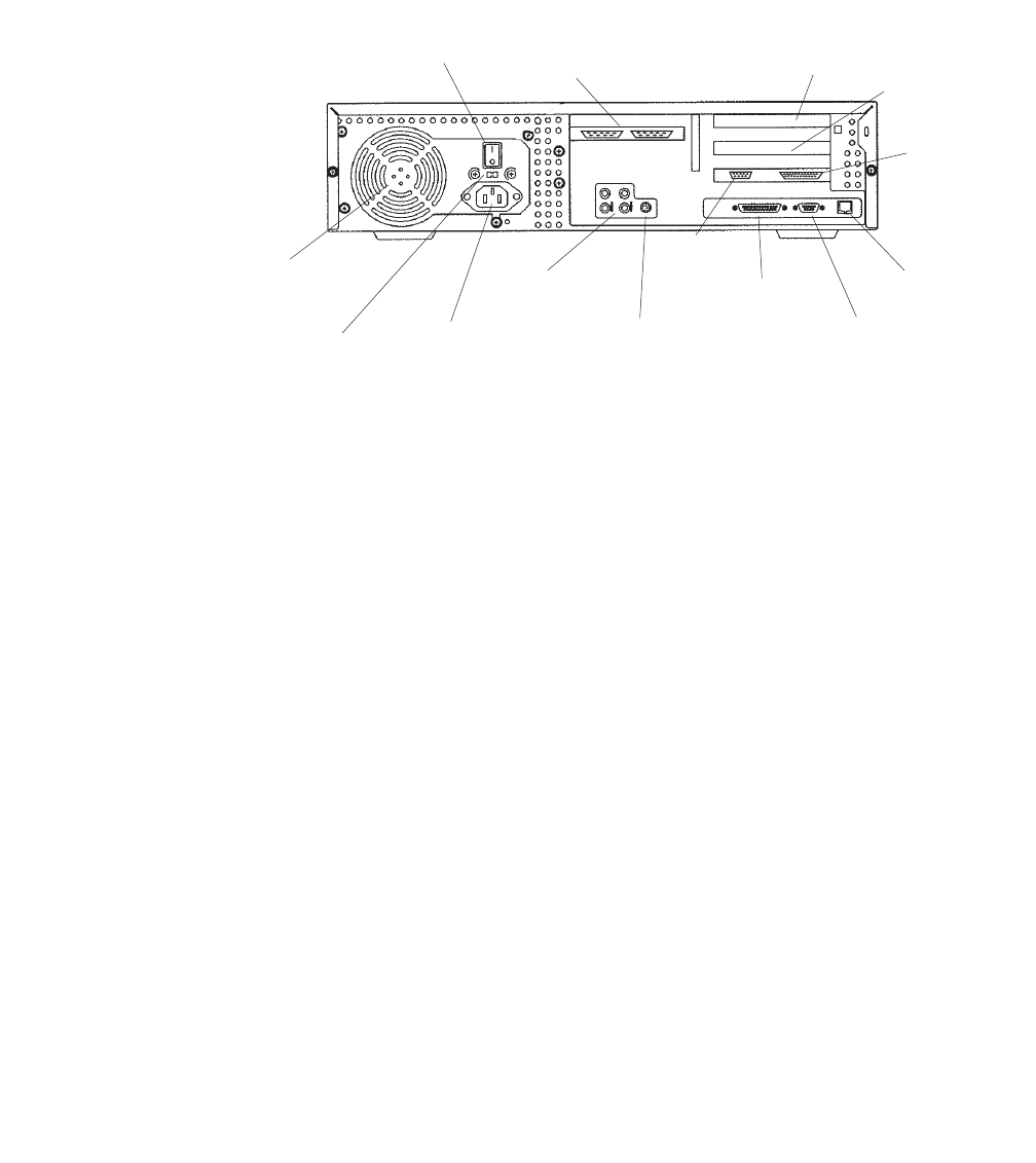
Rear Panel (with UltraSCSI card)
This figure shows the rear panel when you have an UltraSCSI card, which is usually
installed in PCI slot 2. The UltraSCSI card has two 68-pin SCSI connectors. Other PCI
cards may be installed in slots 1 and 3.
Power
switch
(left)
UltraSCSI
card in
PCI slot 2
PCI
slot 3 PCI
slot 1
Parallel
printer
connector
Twisted-pair
ethernet
connector
VGA
connector
Serial
port A
Serial
port B
Keyboard
connector
Audio
connectors
Power cord
receptacle
Voltage selector
switch (older
models only)
Power
supply fan
u5_back_uscsi.cdr
(right)
(left)
Setting up power
Issue 3.3 February 2003 33
Setting up power
To set up the AC power:
!WARNING:
WARNING: DO NOT turn the computer on until you have verified that the input voltage
selector switch has been set properly. Incorrect voltages will damage
system components.
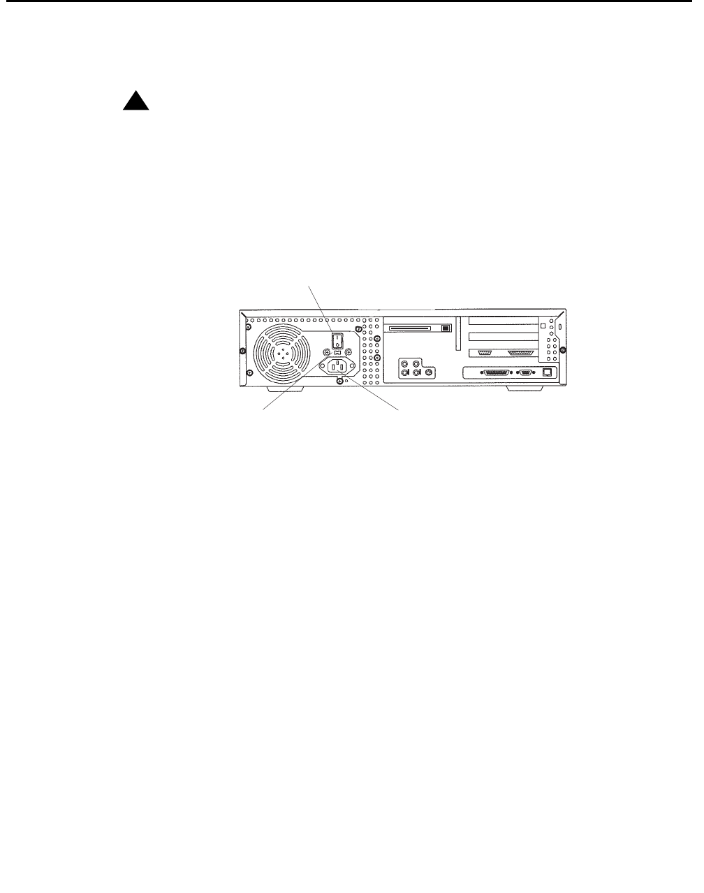
1. On the back of the computer, between the power cord receptacle and the power
switch, locate the voltage selector switch. Newer models of the Ultra 5 use an
autosensing power supply and do not have a voltage selector switch.
2. If your model has a voltage selector switch, set the voltage selector switch to 115
or 230 V AC depending on your installation.
3. Turn off the AC power switch on the back of the computer.
4. Plug the IEC 320 end of the power cord into the AC connector.
For installations outside of the United States and Canada, obtain a power cord for your
local configuration.
5. Plug the power cord from the computer into an outlet on the UPS.
A UPS provides a temporary electrical supply to a computer for several minutes,
depending on the number of components connected to the UPS. For a CMS computer,
a 2KVA minimum UPS is required for all installations. See your UPS documentation to
determine the projected amount of backup battery time for your model. If the system is
without power for longer than the backup time, the system may shut down improperly,
and the customer could lose data.
If a UPS is not being used, you must use a grounded outlet on a dedicated 15-amp
circuit.
Power
switch
Power cord
receptacle
Voltage selector
switch (older
models only)
u5_power.cdr
Installation
34 Avaya CMS Sun Ultra 5 Computer Hardware Installation, Maintenance, and Troubleshooting
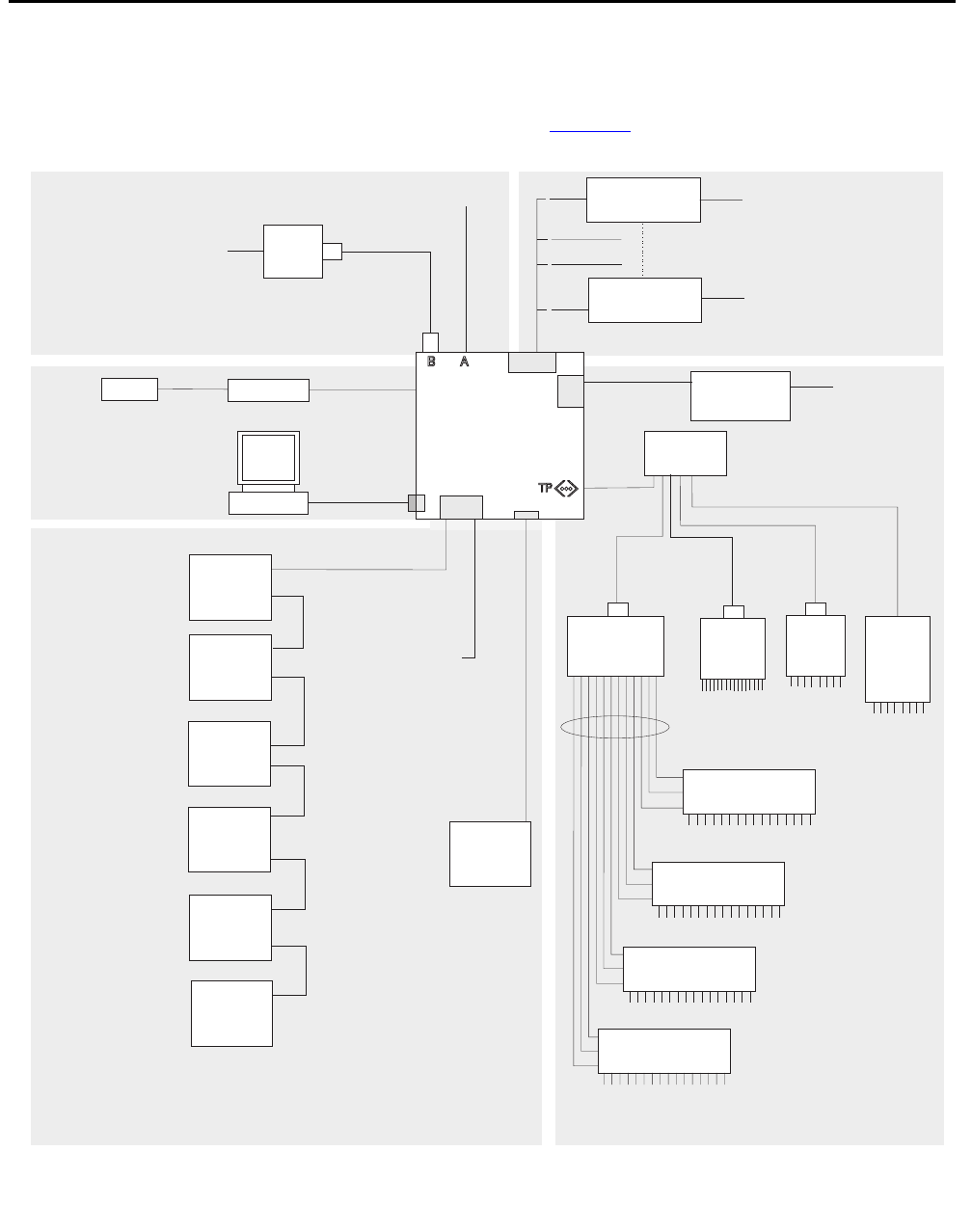
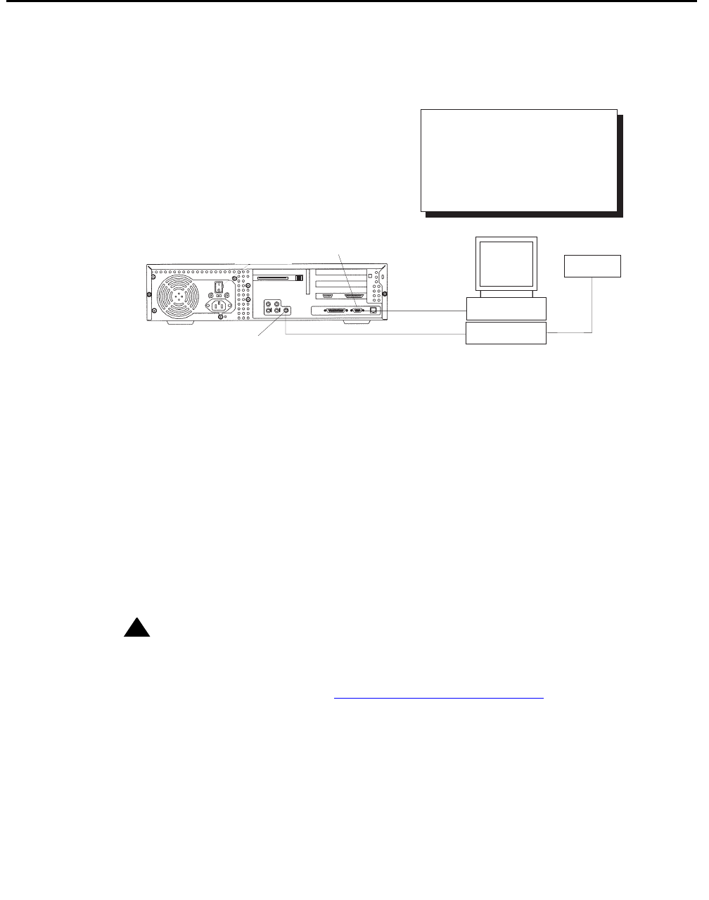
Peripheral connectivity
The following diagram shows how equipment is connected to the Ultra 5 when a SunSwift
card is installed. The callouts are described in Parts list on page 36.
Black Box
RS-449 - RS-232
interface converter
I
J
J
An HSI/P card is used
for up to four ACDs.
A second HSI/P card
is needed for eight ACDs.
Black Box
RS-449 - RS-232
interface converter
System Console
Remote console
N
O
P
M
C
Monitor
AB Keyboard
Mouse
Modem
Telephone line
to remote
maintenance center
8-port
NTS
8-port
NTS
no parallel
port
64-port
NTS
LLL
K
KKKK
NTS patch panel
(16 RS-232 Ports)
NTS patch panel
(16 RS-232 Ports)
NTS patch panel
(16 RS-232 Ports)
NTS patch panel
(16 RS-232 Ports)
Network
hub
Serial port A is
used for single ACD
SAI/P
expander box
(two maximum)
Sun
Ultra 5
Computer
SunSwift
HSI/P
SAI/P
Tape drive 1
(required)
Target 4
Tape drive 2
(optional)
Target 5
Ethernet port for switch
link, R7 and later
(supports up to eight ACDs)
Disk drive 3
(optional)
Target 2
Disk drive 4
(optional)
Target 3
Disk drive 1
(optional)
Target 0
Disk drive 2
(optional)
Target 1
Parallel
printer
16-port
NTS
To terminals,
printers,
modems
To terminals,
printers,
modems To terminals,
printers,
modems
To terminals,
printers,
modems
To terminals,
printers, or modems
H
ST
Q
D
G
G
G
G
G
G
R
ultconp_sunswift.cdr
For detailed network hub and NTS
connectivity, see CMS Terminals,
Printers, and Modems, 585-215-874
For detailed switch link connectivity, see
CMS Switch Connections, Administration,
and Troubleshooting, 585-215-876
For detailed switch link
connectivity, see CMS Switch
Connections, Administration,
and Troubleshooting,
585-215-876
X.25 switch links
System console
External drives and
ethernet switch links
Peripheral connectivity
Issue 3.3 February 2003 35
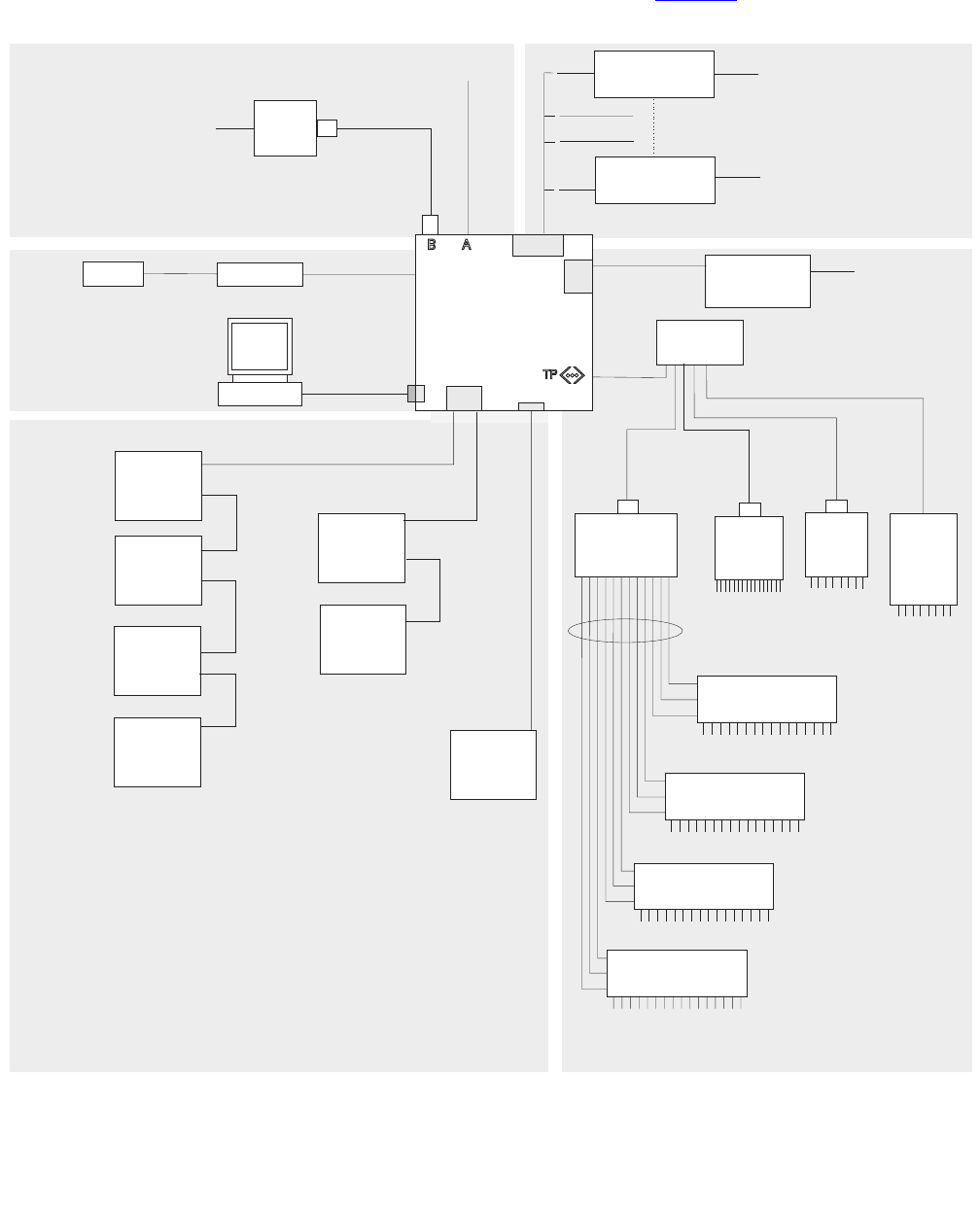
The following diagram shows how equipment is connected to the Ultra 5 when an
UltraSCSI card is installed. The callouts are described in Parts list on page 36.
D
System Console
Remote console
Black Box
RS-449 - RS-232
interface converter
I
N
O
P
M
J
J
C
Monitor
AB Keyboard
Mouse
An HSI/P card is used
for up to four ACDs.
A second HSI/P card
is needed for eight ACDs.
Modem
Telephone line
to remote
maintenance center
8-port
NTS
8-port
NTS
no parallel
port
64-port
NTS
LLL
NTS patch panel
(16 RS-232 Ports)
NTS patch panel
(16 RS-232 Ports)
NTS patch panel
(16 RS-232 Ports)
NTS patch panel
(16 RS-232 Ports)
Network
hub
E
F
G
G
G
G
R
F
SAI/P
expander box
(two maximum)
Sun
Ultra 5
Computer
Ultra
SCSI
HSI/P
SAI/P
Tape drive 1
(required)
Target 4
Tape drive 2
(optional)
Target 5
Left SCSI Right
SCSI
Disk drive 3
(optional)
Target 2
Disk drive 4
(optional)
Target 3
Disk drive 1
(optional)
Target 0
Disk drive 2
(optional)
Target 1
Parallel
printer
16-port
NTS
To terminals,
printers,
modems
To terminals,
printers,
modems To terminals,
printers,
modems
To terminals,
printers,
modems
K
K
K
K
K
Black Box
RS-449 - RS-232
interface converter
To terminals,
printers, or modems
H
ST
Q
Serial port A is
used for single ACD
NOTE: The “Left/Right” designation for the
UltraSCSI card is based on the card
being in slot 2. If the UltraSCSI card is in
slot 1 or 3, connect the disk drives on the
right and the tape drives on the left.
ultconp.cdr
For detailed network hub and NTS
connectivity, see CMS Terminals,
Printers, and Modems, 585-215-874
For detailed switch link connectivity, see
CMS Switch Connections, Administration,
and Troubleshooting, 585-215-876
X.25 switch links
System console
External drives
Installation
36 Avaya CMS Sun Ultra 5 Computer Hardware Installation, Maintenance, and Troubleshooting
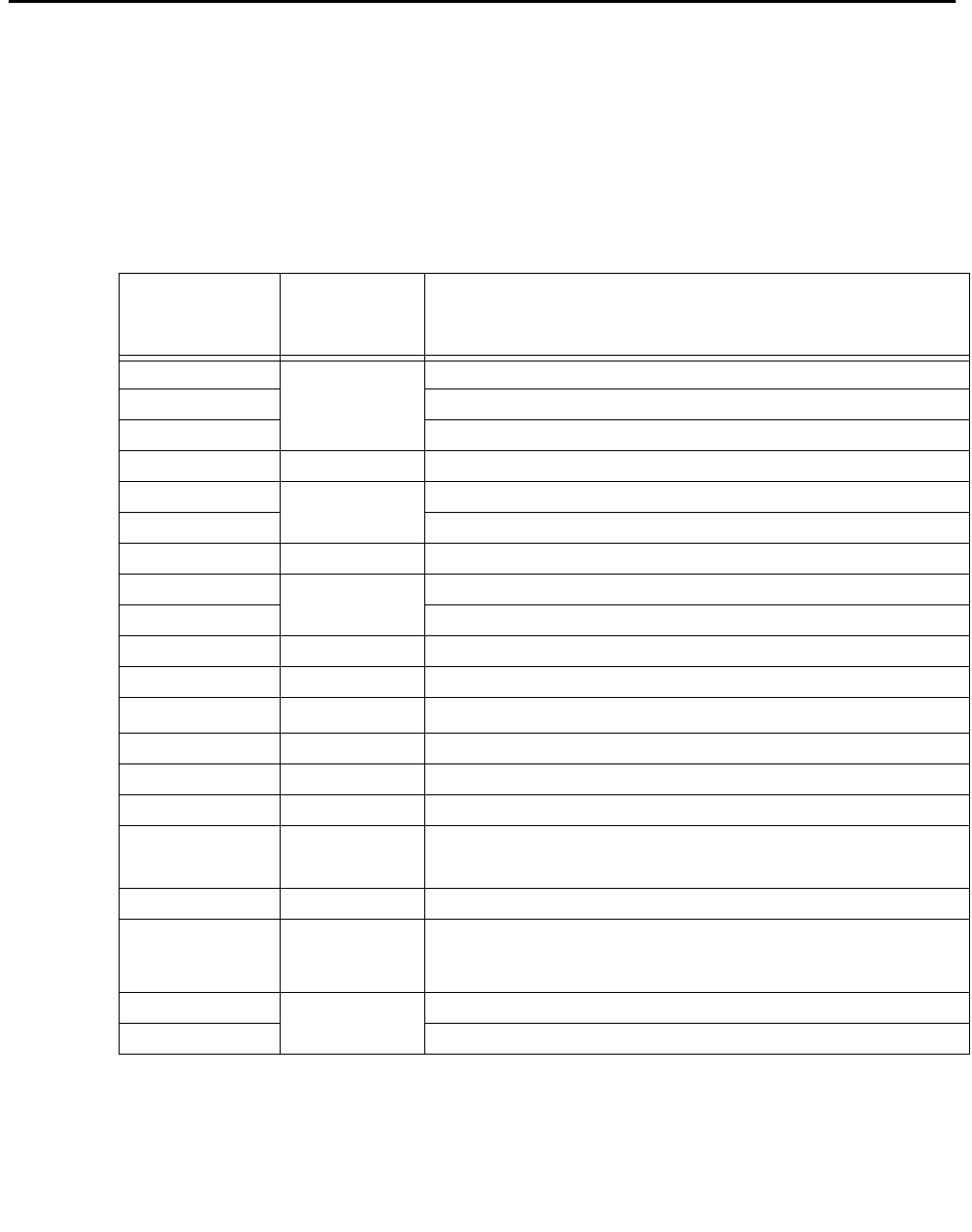
Parts list
The following table lists parts that are required to connect most of the external devices to
the Ultra 5 computer. For information about connecting terminals, printers, and modems to
the Ultra 5 computer, see Avaya CMS Terminals, Printers, and Modems, 585-215-874. For
information about switch connections for CMS, see Avaya CMS Switch Connections,
Administration, and Troubleshooting, 585-215-876.
Connectivity
diagram
call out
Comcode, or
part of
comcode
Description
A1
1. Sun Microsystems provides maintenance sparing for these parts.
N/A2
2. The comcode for this bundle changes regularly and may not be ordered for maintenance spares, so
it is not listed in the table. This bundle includes the processor, peripherals, and other equipment.
Keyboard cable
B1Mouse with cable
C1Monitor cable
D1407938679 SunSwift card (10/100Mbps F/W UltraSCSI PCI Adapter)
E1408106664 UltraSCSI card (Dual-port PCI Adapter)
F168-to-68 pin VHDCI cable (two provided)
G1407934470 68-to-68 pin SCSI cable and AC power cord
H1408128288 HSI/P card (up to two may be installed)
I1Quad cable (one per HSI/P card)
J 407086818 RS-449 cable (10 feet, 3 meters)
K 407086826 Category 5 UTP cord (10 feet, 3 meters)
L 407086859 CentreCOM® transceiver
M 846373413 DB9-to-RJ45 straight-through modem adapter
N 846983039 10-wire modular cable (10 feet, 3 meters)
O 846362770 RJ45-to-DB25 remote console adapter
P 407633999
Varies Sportster® 33.6 remote console modem
Comsphere® 3910 remote console modem
Q 408045326 Parallel printer cable
R1N/A2
N/A
407925718
DDS4 4mm tape drive (20/40-GB)
SLR5 QIC tape drive (4/8-GB)
XL/XS/DX 8mm tape drive (7/14-GB)
S1408128247 SAI/P card (up to two may be installed)
T1SAI/P expander box (one per SAI/P card)
Connecting the monitor and keyboard
Issue 3.3 February 2003 37
Connecting the monitor and keyboard
The following figure shows how to connect the monitor and keyboard to the Ultra 5.
To connect the monitor and keyboard:
1. Make sure the computer power switch is set to off.
2. Connect the following components:
●Keyboard (connects to the keyboard connector)
●Mouse (connects to the keyboard)
●Monitor (connects to the VGA connector)
●Power cord (connects to the UPS or wall outlet)
This basic configuration represents the system console terminal.
!
CAUTION:
CAUTION: Once you have connected the keyboard and power-up the system, do not
disconnect the keyboard while the system is in operation. If the keyboard
becomes unplugged, see Keyboard becomes unplugged on page 183 for
recovery procedures.
C
A
B
Keyboard
Mouse
Monitor
Key:
A = Keyboard cable
B = Mouse and cable
C = Monitor/video cable
VGA
connector
Keyboard
connector
u5_console.cdr
Installation
38 Avaya CMS Sun Ultra 5 Computer Hardware Installation, Maintenance, and Troubleshooting
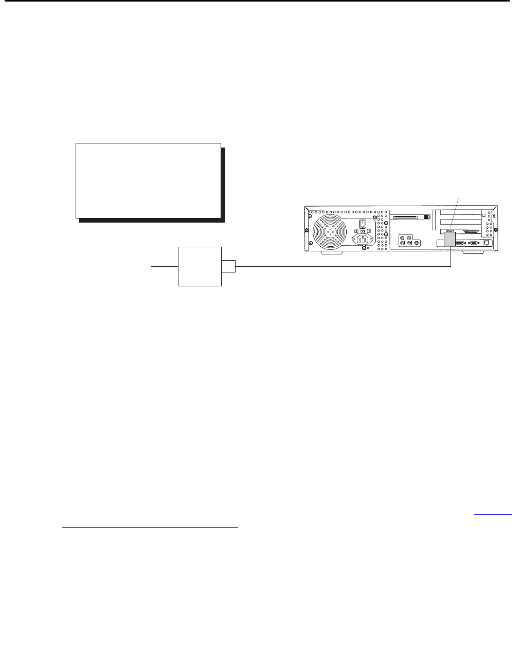
Connecting the remote console modem
This section describes how to connect the remote console modem to the computer. This
modem allows personnel at a remote support center to dial in and do maintenance on the
computer. The modem is a U.S. Robotics Sportster 33.6 Faxmodem, a Paradyne
Comsphere 3910 modem, or a modem provided locally.
The following figure shows remote console modem connectivity.
.
To connect the remote console modem:
1. Connect the DB9-to-RJ45 straight-through adapter (M) to serial port B on the back of
the Ultra 5.
2. Connect the modular cord (N) to the RJ45 end of the adapter (M).
3. Connect the other end of the modular cord (N) to the RJ45 end of the RJ45-to-DB25
remote console adapter (O).
4. Connect the remote console adapter (O) to the RS-232C port on the modem. The
RS-232C port on the Comsphere 3910 is labeled “DTE1.”
5. Connect the telephone line to the jack labeled “LINE” on the Sportster modem, or
labeled “DIAL” on the Comsphere 3910 modem.
6. Connect the power cable to the modem and plug into a socket.
Do not turn the power on yet. Instructions for powering on the modem are given in Setting
the remote console modem options on page 50.
Serial
port B
Modem
Telephone line
to remote
maintenance center N
O
Modem
Key:
M = DB9-RJ45 adapter
N = Modular cord
O = RJ45-DB25 adapter
u5_remconsole.cdr
M

Connecting to external interfaces
Issue 3.3 February 2003 39
Connecting to external interfaces
A variety of external I/O components and interfaces may be required depending on the
configuration chosen by the customer. This section describes some of the most likely
configurations.
Refer to the following subsections as appropriate for your installation:
●Connecting the switch link on page 39
●Connecting the serial port expander box on page 40
●Connecting external SCSI devices on page 41
Procedures for connecting a network hub unit and an NTS are found in Avaya CMS
Terminals, Printers, and Modems, 585-215-874.
Connecting the switch link
There are two ways to connect the CMS computer to a switch:
●using TCP/IP over a local area network (LAN)
●using X.25 protocol over a hard-wired or switched link
Note:
Note: Some CMS loads do not support the X.25 protocol. Contact the National
Customer Care Center or consult with your product distributor or
representative to verify if the X.25 protocol is supported on your CMS
system.
One CMS computer can collect data from up to eight different switches. To the CMS
computer, each switch represents one ACD. Depending on the release of the switch and
the release of the CMS software, you can have all switches connected using TCP/IP, all
switches connected using X.25 protocol, or some combination of the two protocols.
For detailed information about how to connect and administer the switch link, see Avaya
CMS Switch Connections, Administration, and Troubleshooting, 585-215-876.
Installation
40 Avaya CMS Sun Ultra 5 Computer Hardware Installation, Maintenance, and Troubleshooting
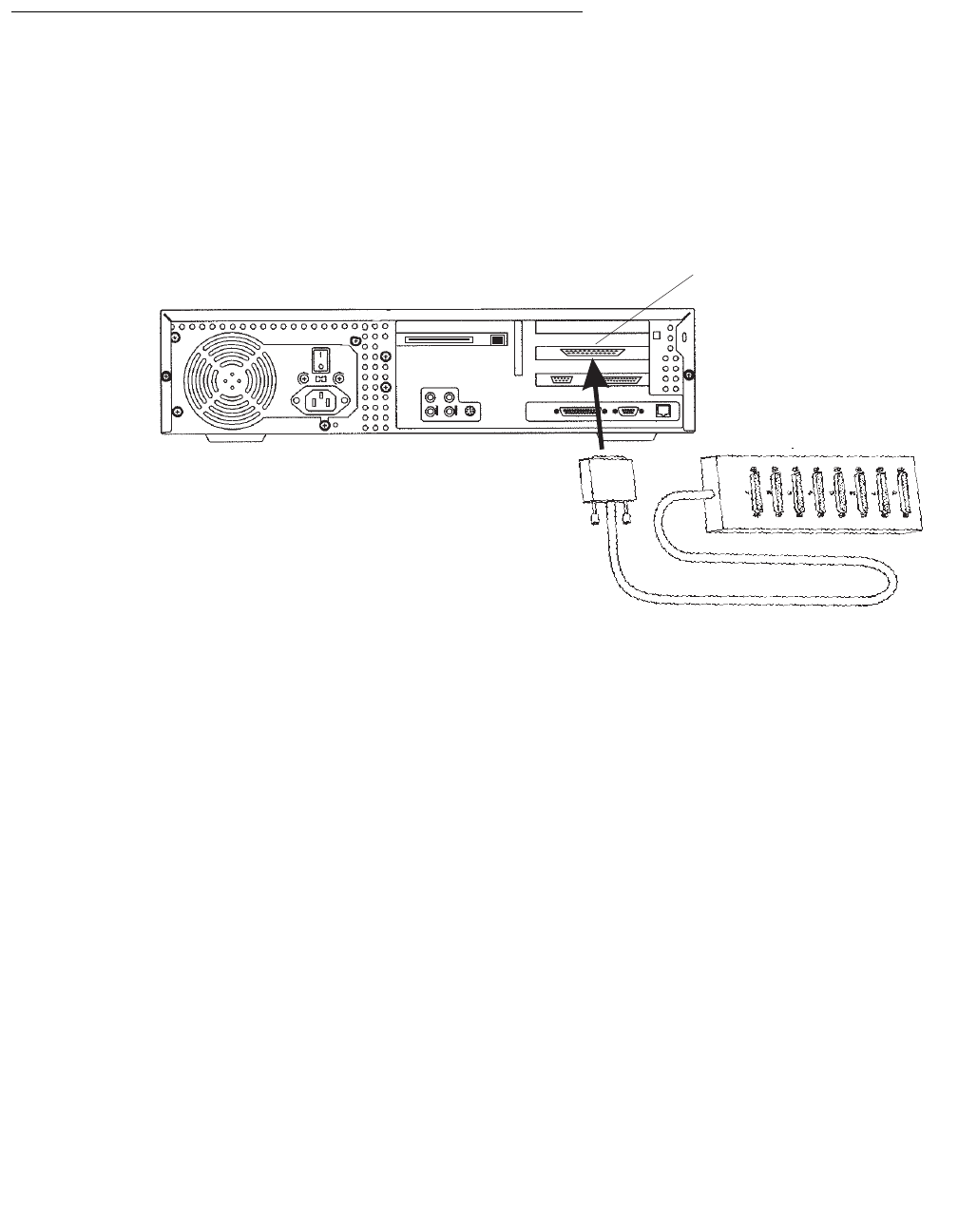
Connecting the serial port expander box
To connect serial devices to the Ultra 5, you can use a Serial Asynchronous Interface/PCI
(SAI/P) expander box. The SAI/P card is used to connect terminals, printers, and modems
to the computer. Each SAI/P card is shipped with an expander box that attaches to the
SAI/P card and breaks out eight RS232 serial ports (see the figure below). There can be
up to two SAI/P cards and expander boxes on each Ultra 5.
SAI/P card
u5_saip_box.cdr
SAI/P expander
box
Connecting to external interfaces
Issue 3.3 February 2003 41
Connecting external SCSI devices
This section describes how to connect the SCSI devices (tape drives and disk drives) to
the Ultra 5 computer. SCSI devices connect to either the SunSwift card or to the
Dual-Channel UltraSCSI card.
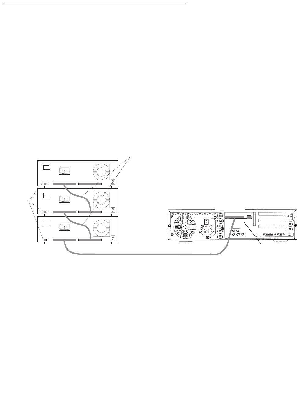
SunSwift connections
The following figure shows how to connect UniPack SCSI disk drives and tape drives to a
SunSwift card. A 68-to-68-pin SCSI cable connects from the SunSwift PCI card on the
back of the computer to the IN connector on the back of the SCSI device that is closest to
the computer. If you have more than one SunSwift card, connect the drives to the card in
the lowest slot number. A 68-to-68 pin SCSI cable connects from the OUT connector of
that device to the IN connector of the next device. Continue this process until all assigned
devices are connected in the SCSI chain.
.
When connecting SCSI devices, the last device in the chain MUST be terminated, either
via an auto-terminated device or with a manual terminator.
When using an auto-terminated SCSI device, you do not need to connect a SCSI
terminator to the OUT connector of the last SCSI device in the chain. To verify that the last
device is auto-terminated, check the LEDs labeled Auto Term High and Auto Term Low on
the back panel of the device. In a CMS configuration, both LEDs are lit on the last device in
the SCSI chain. If a device in the SCSI chain is not the last device, neither termination LED
is lit.
When using a manually-terminated device, you must connect a SCSI terminator to the
OUT connector of the last SCSI device in the chain. When you connect the SCSI
terminator to the OUT connector, the LED on the terminator is lit.
Stack of three
external SCSI devices
SunSwift card
in PCI slot 2
Back panel of Ultra 5
IN
IN
IN
OUT
OUT
OUT
68-to-68 pin SCSI cable
Target
address
switch
68-to-68 pin SCSI cable
scsi_sunswift.cdr
Installation
42 Avaya CMS Sun Ultra 5 Computer Hardware Installation, Maintenance, and Troubleshooting
The following figure shows the SCSI cabling schemes that are possible with a SunSwift
card that is installed in an Ultra 5 computer.
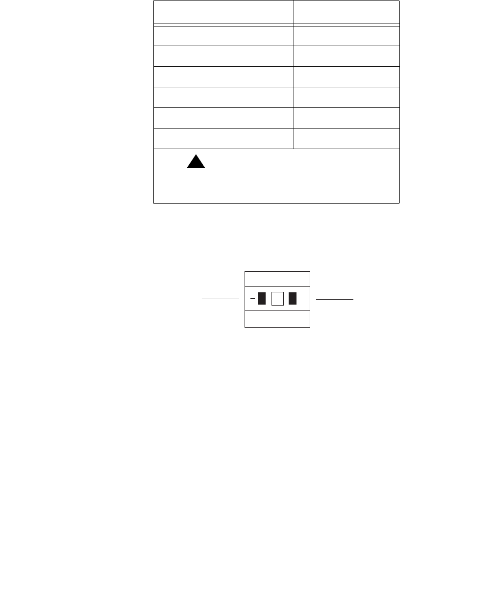
SCSI devices are addressed as shown in the following table.
The addresses are set using the target address switches on the back of each SCSI device.
Before setting the target address, make sure that the power is off on the SCSI devices.
SCSI
Connector
UniPack Disk
Drive 1
(optional)
UniPack Disk
Drive 2
(optional)
UniPack Disk
Drive 3
(optional)
UniPack Disk
Drive 4
(optional)
UniPack
Tape Drive 1
(required)
UniPack
Tape Drive 2
(optional)
WWW
WW W WA
WW
W
68-68 68-68 68-68 68-68 68-68
W = 68-68 pin SCSI cable
A = Auto-terminated
W
68-68
W
scsicble_swift.cdr
Device Address
Disk drive 1 0
Disk drive 2 1
Disk drive 3 2
Disk drive 4 3
Tape drive 1 4
Tape drive 2 5
!Important:
!Important:
Important: Do not use a target address
greater than 5.
Press this side to increase
the address number.
Press this side to decrease
the address number.
+
2
scsiidsw.cdr

Connecting to external interfaces
Issue 3.3 February 2003 43
UltraSCSI connections
The following figure shows how to connect UniPack SCSI disk drives and tape drives to an
UltraSCSI card. A 68-to-68-pin VHDCI SCSI cable connects from the UltraSCSI PCI card
on the back of the computer to the IN connector on the back of the SCSI device that is
closest to the computer. A 68-to-68 pin SCSI cable connects from the OUT connector of
that device to the IN connector of the next device. Continue this process until all assigned
devices are connected in the SCSI chain.
When connecting SCSI devices, the last device in the chain MUST be terminated, either
via an auto-terminated device or with a manual terminator.
When using an auto-terminated SCSI device, you do not need to connect a SCSI
terminator to the OUT connector of the last SCSI device in the chain. To verify that the last
device is auto-terminated, check the LEDs labeled Auto Term High and Auto Term Low on
the back panel of the device. In a CMS configuration, both LEDs are lit on the last device in
the SCSI chain. If a device in the SCSI chain is not the last device, neither termination LED
is lit.
When using a manually-terminated device, you must connect a SCSI terminator to the
OUT connector of the last SCSI device in the chain. When you connect the SCSI
terminator to the OUT connector, the LED on the terminator is lit.
68-to-68 pin VHDCI cable
Stack of three
external SCSI devices
Dual-channel
UltraSCSI card in PCI slot 2
IN
IN
IN
OUT
OUT
OUT
68-to-68 pin SCSI cable
Target
address
switch
Back panel of Ultra 5
scsiuni.cdr
(left) (right)

Installation
44 Avaya CMS Sun Ultra 5 Computer Hardware Installation, Maintenance, and Troubleshooting
The following figure shows the SCSI cabling schemes that are possible with an UltraSCSI
card that is installed in slot 2 of an Ultra 5 computer.
Note:
Note: The “Left/Right” designations shown above are based on the UltraSCSI card
being installed in slot 2. If the UltraSCSI card is installed in slots 1 or 3,
connect the disk drives to the right connector and the tape drives to the left
connector.
Left SCSI
Connector
Right SCSI
Connector
UniPack Disk
Drive 1
(optional)
UniPack Disk
Drive 2
(optional)
UniPack Disk
Drive 3
(optional)
UniPack Disk
Drive 4
(optional)
UniPack
Tape Drive 1
(required)
UniPack
Tape Drive 2
(optional)
VV
VV
W W W A
A
W
W W
68-68
68-68
68-68 68-68
68-68
V = 68-68 pin VHDCI cable
W = 68-68 pin SCSI cable
A = Auto-terminated
W
68-68
W
scsicble.cdr
Connecting to external interfaces
Issue 3.3 February 2003 45
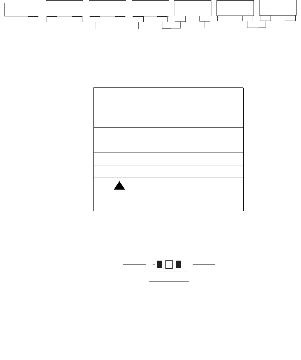
SCSI devices are addressed as shown in the following table.
These addresses are set using the target address switches on the back of each SCSI
device. Before setting the target address, make sure that the power is off on the SCSI
devices.
Device Address
Disk drive 1 0
Disk drive 2 1
Disk drive 3 2
Disk drive 4 3
Tape drive 1 4
Tape drive 2 5
!Important:
!Important:
Important: Do not use a target address
greater than 5.
Press this side to increase
the address number.
Press this side to decrease
the address number.
+
2
scsiidsw.cdr

Installation
46 Avaya CMS Sun Ultra 5 Computer Hardware Installation, Maintenance, and Troubleshooting
Turning the system on and verifying POST
Once you assemble the system, including the external devices that are shipped with your
system, turn the system on and verify POST (Power On Self Test).
To turn the system on and verify POST:
1. Plug the power cord of the UPS into an AC outlet.
2. Turn on the power to the UPS.
3. Turn on all external SCSI devices starting with the device farthest from the system and
working toward the system.
4. Turn on the system monitor.
5. Turn on the system.
Note:
Note: The POST diagnostics will occur each time you turn on the system. The
POST tests the basic system components. This may take several minutes
6. While the system is booting up, press Stop+A simultaneously to put the system in the
monitor mode.
The ok prompt is displayed.
7. Enter the following commands:
setenv auto-boot? false
reset-all
The system resets to the ok prompt.
Turning the system on and verifying POST
Issue 3.3 February 2003 47
8. Enter:
probe-ide
This verifies that the system sees all enhanced integrated drive electronics (EIDE)
devices. A message similar to the following is displayed:
In this example, the devices listed are as follows:
●Device 0 is the primary internal hard drive.
●Device 1 is the optional second internal hard drive, if present.
●Device 2 is the CD-ROM drive.
●Device 3 is the floppy drive, if present.
Note:
Note: The actual devices listed depends on the devices installed on the EIDE bus.
9. Enter:
reset-all
The system resets to the ok prompt.
Device 0 ( Primary Master )
ATA Model: STxxxxxx
Device 1 ( Primary Slave )
Not Present (or) ATA Model: STxxxxxx
Device 2 ( Secondary Master )
Removable ATAPI Model: CRD-xxxxx
Device 3 ( Secondary Slave )
Not Present (or) Removable ATAPI Model: xxxx
Installation
48 Avaya CMS Sun Ultra 5 Computer Hardware Installation, Maintenance, and Troubleshooting
10. Enter:
probe-scsi-all
This verifies that the system sees all external SCSI devices. A message similar to the
following is displayed:
In this example, the devices listed are as follows:
●Target 0 is an external 4.2-GB hard drive.
●Target 4 is an external DDS4 tape drive.
Note:
Note: The actual devices listed depends on the devices installed on the SCSI bus.
11. When you have verified that the system recognizes all of its devices, enter the
following commands:
!
CAUTION:
CAUTION: If you fail to enter these commands, any reboots that you do in the future will
stop at the boot prompt instead of proceeding through the normal boot-up
process.
setenv auto-boot? true
boot -r
The system reboots.
/pci@1f,0/pci@1/pci@1/SUNW,isptwo@4
Target 0
Unit 0 Disk QUANTUM VK4550J SUN4.2G8610
Target 4
Unit 0 Removeable Tape HP C5683A C911

Identifying installed PCI cards
Issue 3.3 February 2003 49
Identifying installed PCI cards
If there are problems with the PCI cards, do the following to troubleshoot the problem. If all
PCI cards are operational, you can skip this section.
At the command prompt, enter:
/usr/platform/‘uname -m‘/sbin/prtdiag -v | pg
In the section called IO Cards, there is a listing of the PCI cards. The following are
examples of some of the entries you may see. The display you see depends on your
specific configuration.
In this example:
●Slot 1 is an SAI/P card
●Slot 2 is a SunSwift card
●Slot 3 is an HSI/P card
.
.
========================= IO Cards =========================
Bus# Freq
Brd Type MHz Slot Name Model
--- ---- ---- ---- -------------------------------- ----------------------
0 PCI-1 33 1 ebus
0 PCI-1 33 1 network-SUNW,hme
0 PCI-1 33 2 SUNW,m64B ATY,GT-B
0 PCI-1 33 3 ide-pci1095,646
0 PCI-2 33 1 pci114f,1c-pci114f,1c
0 PCI-2 33 2 pci-pci1011,24
0 PCI-2 33 3 pci1214,334-pci1214,334
.
.
Installation
50 Avaya CMS Sun Ultra 5 Computer Hardware Installation, Maintenance, and Troubleshooting
Setting the remote console modem options
The computer supports the U.S. Robotics Sportster 33.6 Faxmodem and the Paradyne
Comsphere 3910 modem for remote console access. The options for any other modems
must be set based on local instructions.
For instructions for connecting the modem, see Connecting the remote console modem on
page 38.
Sportster 33.6 faxmodem
The Sportster 33.6 faxmodems are optioned at the factory. Use this procedure only if the
modem has lost the factory option settings.
To set the options for the Sportster 33.6 faxmodem:
1. Set DIP switches 1, 3, 7, and 8 on the back panel of the Sportster modem to the down
(ON) position, and switches 2, 4, 5, and 6 to the up (OFF) position.
2. Turn on the remote console modem.
3. At the system console, log in as root.
4. Enter:
/cms/install/bin/abcadm -r ttyb
The following message is displayed:
5. Enter: y
The following message is displayed:
The port monitor turns off.
ttyb is currently set to be incoming
Are you sure you want to change it? [y,n,?]
ttyb administration removed
Setting the remote console modem options
Issue 3.3 February 2003 51
6. Enter the following command:
cu -s 9600 -b 8 -l cua/b
The following message is displayed:
7. Enter the following commands:
at&f1 (loads the factory default configuration into active memory)
at&w0 (writes the current configuration to NVRAM template Y0)
Note:
Note: Use numerical ones and zeros when entering the options.
8. After you enter the options, disconnect from the modem by entering a tilde and a
period (~.).
9. Set DIP switches 4 and 8 on the back panel of the Sportster modem to the down (ON)
position. Set all other DIP switches to the up (OFF) position.
10. Reset the modem by turning the power off and back on.
11. Enter:
/cms/install/bin/abcadm -i -b 9600 ttya
The Terminal Ready (TR) LED lights on the modem and the following message is
displayed:
12. If the TR LED is not lit, enter:
ps -ef | grep sac
A message similar to the following should be displayed:
Additional references – For additional information, see the U.S. Robotics Sportster
Modems Users Guide.
Connected
ttya set to incoming port 9600 baud
root 377 1 0 14:39:30 ? 0:00 /usr/lib/saf/sac -t 300
root 9723 9666 0 09:16:26 pts/9 0:00 grep sac
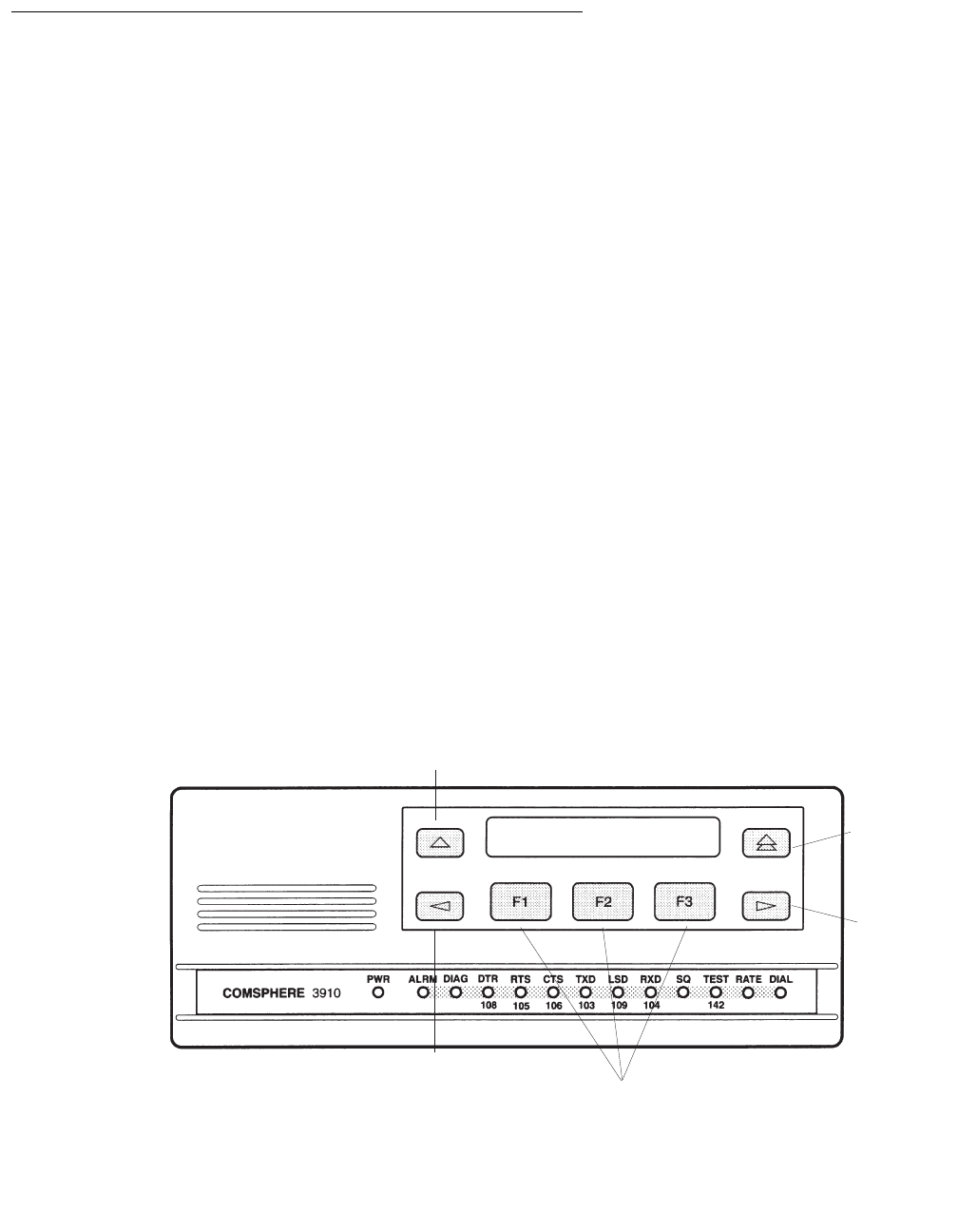
Installation
52 Avaya CMS Sun Ultra 5 Computer Hardware Installation, Maintenance, and Troubleshooting
Paradyne Comsphere 3910 modem
The Paradyne Comsphere 3910 modem is used for many locations outside of the United
States. These modems are not optioned at the factory.
Recommended options
The recommended options for the Comsphere 3910 modem include selecting the
factory-preset defaults for “UNIX_Dial” with the following two changes:
●Asynchronous DTE Rate is changed to 9600
●Dial Line Rate is changed to 9600 (V32b)
Option buttons
The seven buttons that are used to set the modem options include:
●Single Up Arrow. Move up one level in the menu tree
●Double Up Arrow. Move to the top-level menu
●Left Arrow. Move to the previous choice for the current level in the menu tree
●Right Arrow. Move to subsequent choice for the current level in the menu tree
●Function 1 (F1). Select the choice, if any, that is currently displayed above F1
●Function 2 (F2). Select the choice, if any, that is currently displayed above F2
●Function 3 (F3). Select the choice, if any, that is currently displayed above F3
Right
Arrow
Function keys
Double Up
Arrow
S
ingle Up
Arrow
Left
Arrow
3910.cdr

Setting the remote console modem options
Issue 3.3 February 2003 53
Setting the options
To set the options on the Comsphere 3910, use the following procedures.
Configuring Factory/Async_Dial
1. Press F2 to select “Configure.”
“Ld EditArea frm” is displayed.
2. Press the Right Arrow four times.
“Factory” is displayed.
3. Press F1 to select “Factory.”
“Ld Fact Preset:” is displayed.
4. Press Right Arrow four times.
5. Press F1 to select “UNIX_Dial.”
6. Press F3 to select “Save.”
“Sav EditArea to” is displayed.
7. Press F1 to save to “Active(Saved).”
Since you are changing the active area to a new set of options (that is,
“Factory/Async_Dial”), the modem automatically performs another Power-On-Self-Test
(POST). Since the new options match the way the modem is connected, the ALRM
LED does not turn red. “Idle: 19.2” and “Status Configure” are displayed. To return to
the top-level menu, press the Double Up Arrow.
Setting the data rate
1. Press F2 to select “Configure.”
“Ld EditArea frm” is displayed.
2. Press the Right Arrow once.
“Active(Saved)” is displayed.
3. Press F1.
“Choose Function” is displayed.
4. Press F1 to select “Edit.”
“Edit StrapGroup” is displayed.
5. Press F1 to select “DTE_Interface.”
“Async/Sync Mode” is displayed.
6. Press F1 to select “Nxt.”
“Async DTE Rate” is displayed.

Installation
54 Avaya CMS Sun Ultra 5 Computer Hardware Installation, Maintenance, and Troubleshooting
7. Press the Right Arrow five times to display “9600.”
8. Press F2 to select “9600.”
Setting the handshake options
1. Press F1 for “Nxt.”
“Asyn #Data Bits (8)” is displayed.
2. Press F1 for “Nxt.”
“Asyn Parity Bit (None)” is displayed.
3. Press F1 for “Nxt.”
“Asyn #Stop Bits (1)” is displayed.
4. Press F1 for “Nxt.”
“DTR Action (Ignore)” is displayed.
5. Press F1 for “Nxt.”
“DSR Control (Forced_On)” is displayed.
6. Press F1 for “Nxt.”
“RTS Action (Ignore)” is displayed.
7. Press F1 for “Nxt.”
“CTS Control (WinkWhenDisc)” is displayed.
8. Press F1 for “Nxt.”
“RTS/CTS Delay (0 msec)” is displayed.
9. Press F1 for “Nxt.”
“LSD Control (WinkWhenDisc)” is displayed.
10. Press F1 for “Nxt.”
“CT111_Rate Cntl (Disable)” is displayed.
11. Press F1 for “Nxt.”
“DTE_Rate=VF (Disable)” is displayed.
12. Press F1 for “Nxt.”
“Extend Main Ch. (Disable)” is displayed.
13. Press F1 for “End.”
“Edit StrapGroup” is displayed.

Setting the remote console modem options
Issue 3.3 February 2003 55
Setting the Dial_Line strap group
1. Press the Right Arrow three times to get to the “Dial_Line” strap group. Nothing needs
to be changed for CMS in the “DTE_Dialer” or “Line_Dialer” strap groups, so you can
skip them.
2. Press F1 to edit the “Dial_Line” strap group.
“Dial Line Rate” is displayed.
3. Press the Right Arrow four times for “9600(V32b).”
4. Press F2 to select “9600(V32b).”
5. Press F1 for “Nxt.”
“V32bis Automode (Enable)” is displayed.
6. Press F1 for “Nxt.”
“V32bis Autorate (Enable)” is displayed.
7. Press F1 for “Nxt.”
“Dial Tx Level (Permissv (-9))” is displayed.
8. Press F1 for “Nxt.”
“V22b Guard Tone (Disable)” is displayed.
9. Press F1 for “Nxt.”
“V32bis Train (Long)” is displayed.
10. Press F1 for “End.”
“Edit StrapGroup” is displayed. The other strap groups (“V42/MNP/Buffer,” “Test,”
“Misc,” and “Security”) are not changed for CMS.
Saving your settings
1. Press the Single Up Arrow to display “Choose Function” and “Edit Save.”
2. Press F3 to select “Save.”
“Save EditArea to” is displayed.
3. Press F1 to select “Active(Saved).”
“Command Complete” is displayed.
4. Press the Single Up Arrow again to display “Save EditArea to.”
5. Press the Right Arrow once to select “Customer 1.”
6. Press F1 to save to “Customer 1.”
“Command Complete” is displayed.

Installation
56 Avaya CMS Sun Ultra 5 Computer Hardware Installation, Maintenance, and Troubleshooting
7. Press the Double Up Arrow.
“Idle: 9600” and “Status Configure” are displayed. If the modem is powered off, it
should return to this state when it is powered on.
8. To check the status of the Comsphere 3910 modem, use the “Status” choice in the
top level menu, or use the Right and Left Arrow buttons to view other top-level menu
choices.

Turning the system over for provisioning
Issue 3.3 February 2003 57
Turning the system over for provisioning
After completing the physical installation of the system, the installation continues with
software provisioning. This is often done with the support of the Avaya CMS Provisioning
group. Provisioning the system consists of the following:
●Setting up CMS
●Authorizing features
●Adding logins and passwords
●Testing the software
To continue with provisioning, see the chapter “Turning the system over to the customer” in
the software installation, maintenance, and troubleshooting document appropriate for your
version of CMS.

Installation
58 Avaya CMS Sun Ultra 5 Computer Hardware Installation, Maintenance, and Troubleshooting

Issue 3.3 February 2003 59
Maintenance
Overview
This chapter describes the following maintenance procedures:
●Computer layout on page 60
●ESD precautions on page 63
●Maintaining PCI cards on page 64
●Maintaining disk drives on page 83
●Replacing the CD-ROM drive on page 130
●Maintaining tape drives on page 135
●Adding memory and replacing the CPU on page 147
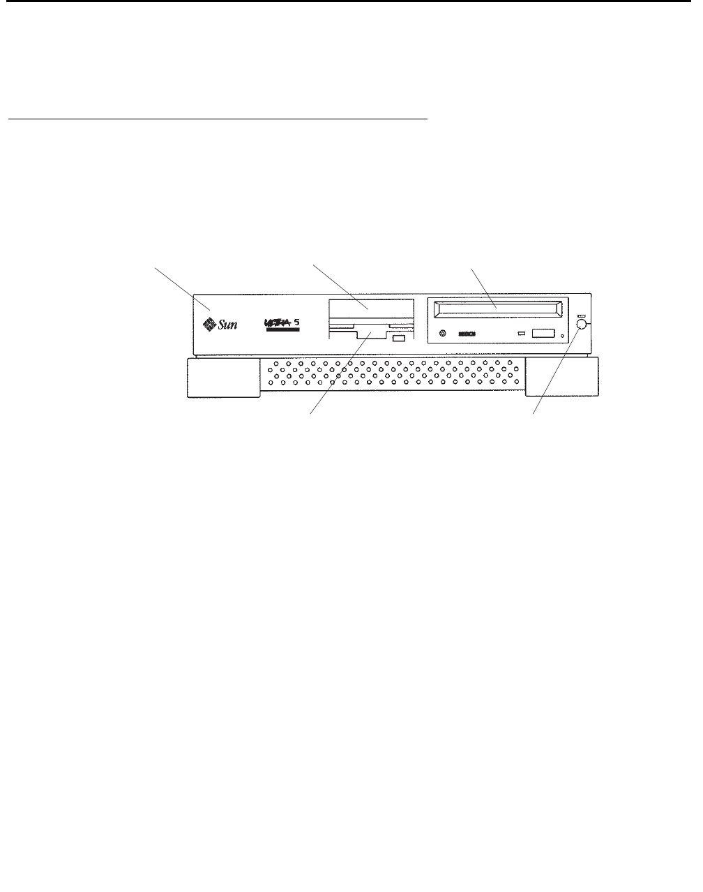
Maintenance
60 Avaya CMS Sun Ultra 5 Computer Hardware Installation, Maintenance, and Troubleshooting
Computer layout
Familiarize yourself with the layout of the Ultra 5.
Front Panel
This figure shows the front panel of the Ultra 5. The diskette drive is not available if the
optional second internal hard drive has been installed.
System
unit
Diskette drive or second
internal hard drive
Standby
switch
CD-ROM
drive
3.5-inch bracket
(spare)
u5_front.cdr
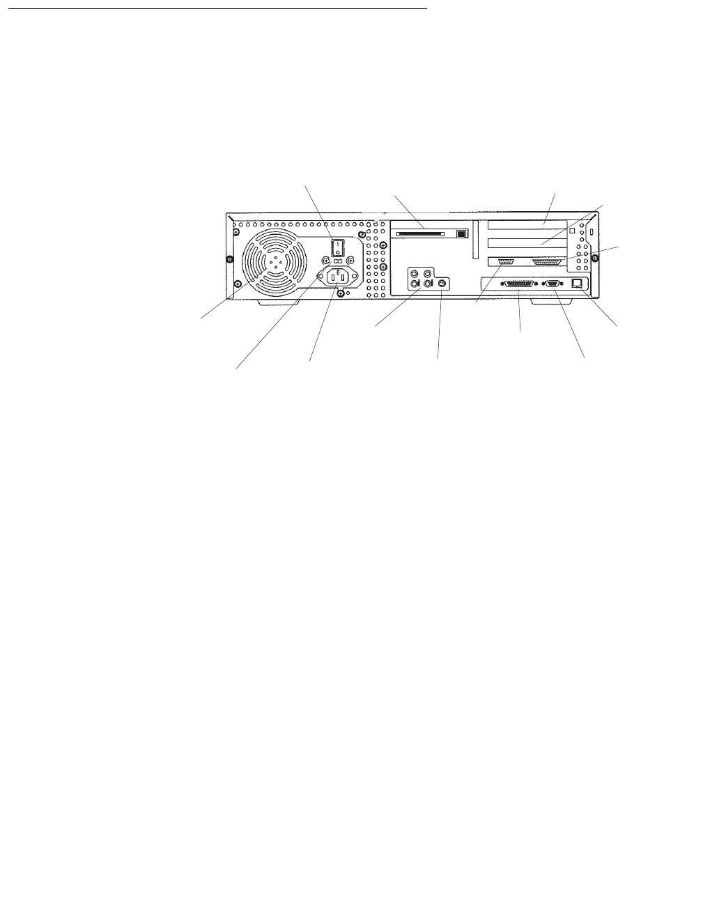
Computer layout
Issue 3.3 February 2003 61
Rear Panel (with SunSwift card)
This figure shows the rear panel when you have a SunSwift card, which is usually installed
in PCI slot 2. The SunSwift card has one 68-pin SCSI connector and one ethernet RJ45
connector. Other PCI cards may be installed in slots 1 and 3.
Power
switch
SunSwift
card in
PCI slot 2
PCI
slot 3 PCI
slot 1
Parallel
printer
connector
Twisted-pair
ethernet
connector
VGA
connector
Serial
port A
Serial
port B
Keyboard
connector
Audio
connectors
Power cord
receptacle
Voltage selector
switch (older
models only)
Power
supply fan
u5_back_sunswift.cdr
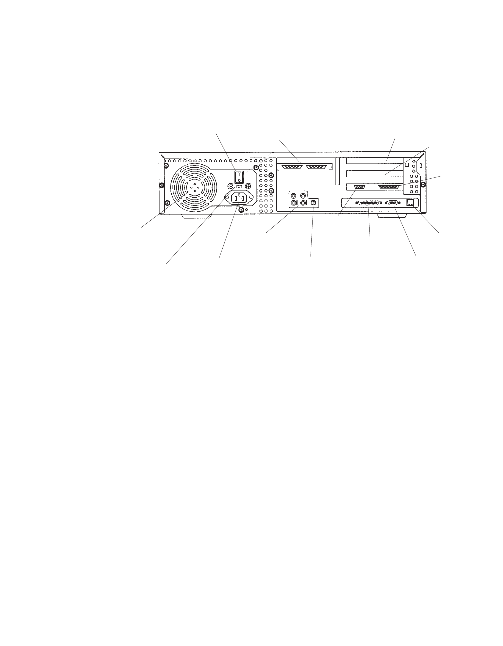
Maintenance
62 Avaya CMS Sun Ultra 5 Computer Hardware Installation, Maintenance, and Troubleshooting
Rear Panel (with UltraSCSI card)
This figure shows the rear panel when you have an UltraSCSI card, which is usually
installed in PCI slot 2. The UltraSCSI card has two 68-pin SCSI connectors. Other PCI
cards may be installed in slots 1 and 3.
Power
switch
(left)
UltraSCSI
card in
PCI slot 2
PCI
slot 3 PCI
slot 1
Parallel
printer
connector
Twisted-pair
ethernet
connector
VGA
connector
Serial
port A
Serial
port B
Keyboard
connector
Audio
connectors
Power cord
receptacle
Voltage selector
switch (older
models only)
Power
supply fan
u5_back_uscsi.cdr
(right)
(left)
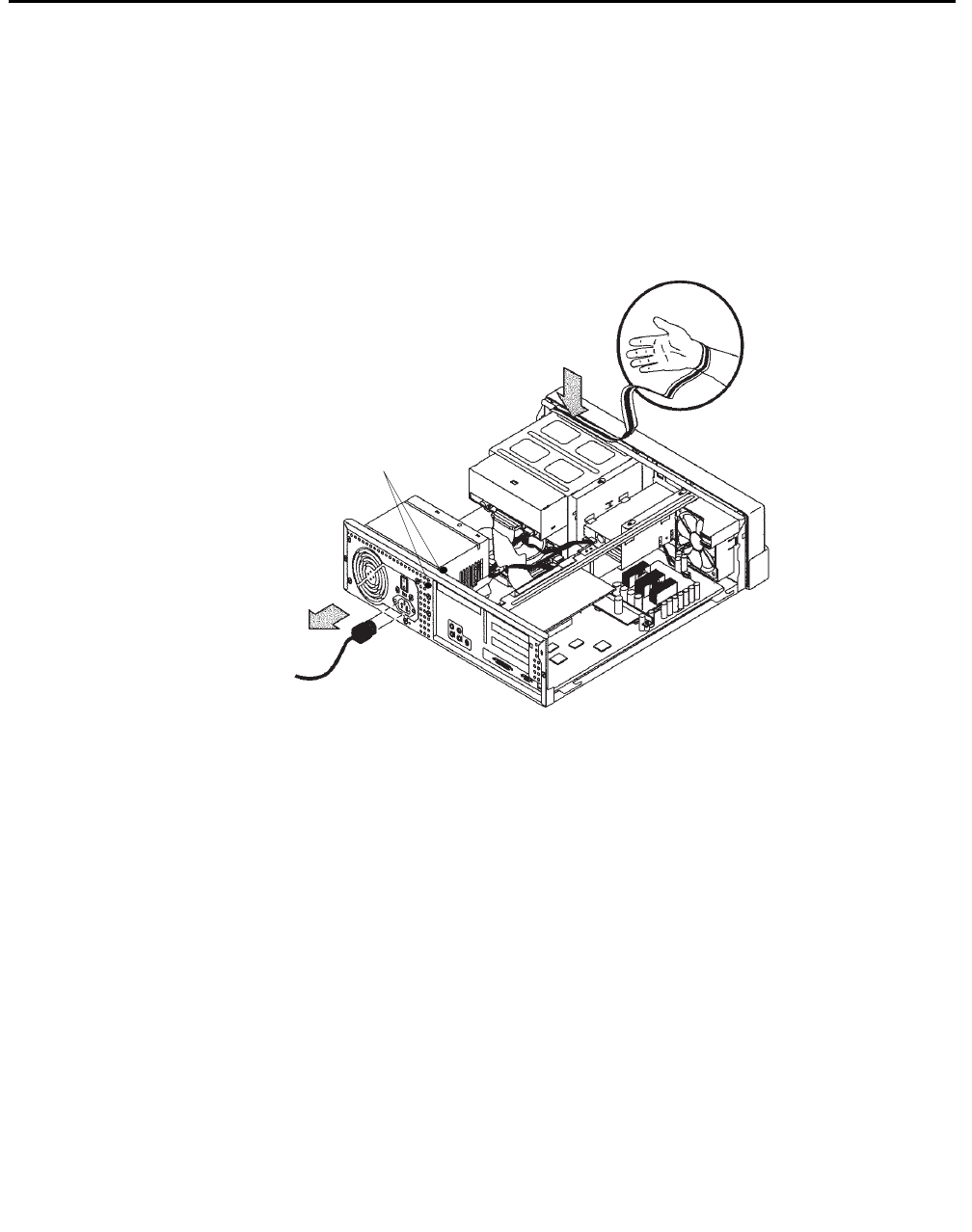
ESD precautions
Issue 3.3 February 2003 63
ESD precautions
Before you work on components inside the Ultra 5 computer:
1. Make sure that the computer is plugged in to AC power.
2. Make sure that the power is off.
3. Attach the Electro-Static Discharge (ESD) wrist strap to the chassis frame and to your
wrist. See the following figure.
4. Unplug the AC power cord.
u5_wriststrap.cdr
PCI slot 2
screws

Maintenance
64 Avaya CMS Sun Ultra 5 Computer Hardware Installation, Maintenance, and Troubleshooting
Maintaining PCI cards
Overview
Procedures in this section include the following:
●Identifying free card slots
●PCI card configuration on page 65
●Installing or removing PCI cards on page 66
●Replacing an UltraSCSI card with a SunSwift card on page 68
●SAI/P cards on page 71
●Installing HSI/P cards on page 77
Required references
You need access to the following documents to do procedures in this section:
●Avaya CMS R3V11 Software Installation, Maintenance, and Troubleshooting,
585-215-115
●Avaya CMS R3V9 Software Installation, Maintenance, and Troubleshooting,
585-215-956
●Avaya CMS R3V8 Software Installation, Maintenance, and Troubleshooting,
585-210-941
●Avaya CMS Software Installation and Setup (R3V5 and R3V6), 585-215-866
●Avaya CMS Switch Connections, Administration, and Troubleshooting, 585-215-876
●Sun Ultra 5 Service Manual
Identifying free card slots
There are three PCI slots on the back of the Ultra 5 computer. Empty slots are covered by
filler panels. Every computer will have either a SunSwift SCSI/Ethernet or UltraSCSI card
installed in Slot 2.
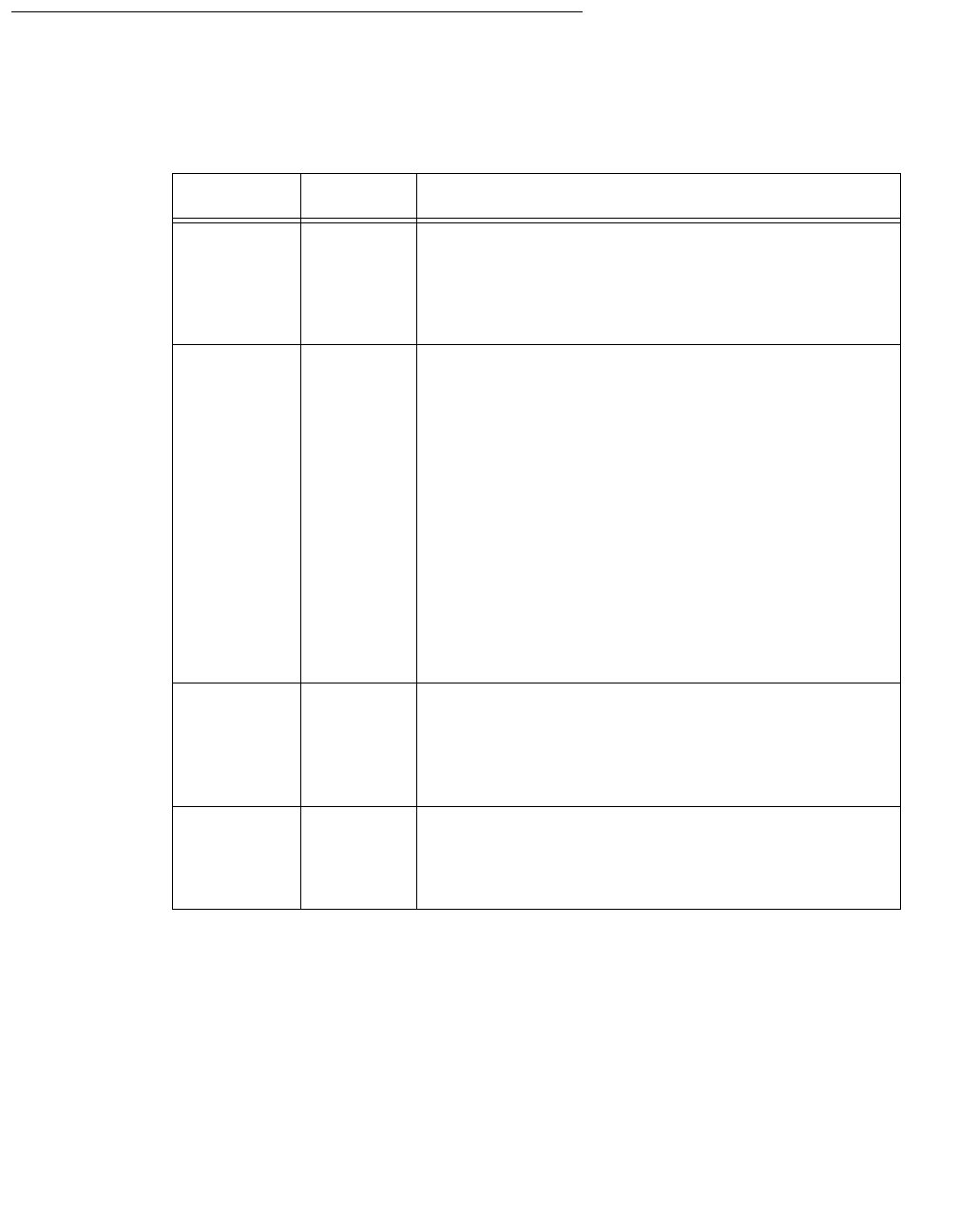
Maintaining PCI cards
Issue 3.3 February 2003 65
PCI card configuration
Depending on your configuration, the PCI cards will be installed in the slots shown below.
Card PCI Slot Comments
SunSwift
or
UltraSCSI
PCI 2, 1,
or 3 Required. A SunSwift card is installed in every
computer to provide a dedicated ethernet
connection to the switch, and a SCSI interface to
external tape and disk drives. Additional SunSwift
cards can be installed in the other slots.
HSI/P PCI 1 or
PCI 3 Optional. HSI/P cards are not required when
using ethernet for switch link connectivity. Use
PCI 1 for the first card, which supports four ACDs.
Use PCI 1 and 3 for two cards, which support
eight ACDs.
Note:
Note: Some CMS loads do not support
the X.25 protocol. Contact the
National Customer Care Center or
consult with your product
distributor or representative to
verify if the X.25 protocol is
supported on your CMS system.
SAI/P PCI 1 or
PCI 3 Optional. SAI/P cards provide serial port
connectivity for printers and terminals. Use PCI 1
for the first card, which supports eight serial
devices. Use PCI 1 and 3 for two cards, which
supports 16 serial ports.
Token Ring PCI 3 Optional. Installation and setup of this card is
done by Professional Services in the United
States, or by special arrangement outside of the
United States.

Maintenance
66 Avaya CMS Sun Ultra 5 Computer Hardware Installation, Maintenance, and Troubleshooting
Installing or removing PCI cards
Use the following general instructions when installing, moving, and removing PCI cards.
Other sections in this chapter describe specific PCI card maintenance instructions. Use
those instructions as appropriate.
Note:
Note: If you plan to install an optional second internal hard drive, install it before
you install any PCI cards.
To install or remove a card:
1. For a system currently in operation, verify that you have a recent CMSADM file system
backup before you change card configurations.
2. Enter:
/usr/sbin/shutdown -y -i0 -g0
This shuts down the system.
3. Turn off the system.
4. Turn off the system monitor.
5. Turn off all external SCSI devices starting with the device closest to the system and
working toward the farthest device.
!WARNING:
WARNING: You must wear an ESD wrist strap when installing or removing hardware
components to prevent electrical discharge that can damage the system.
6. Remove the cover of the Ultra 5.
7. Disconnect the AC power cord.
8. Select an unused slot to add a card, or select what card you are removing.
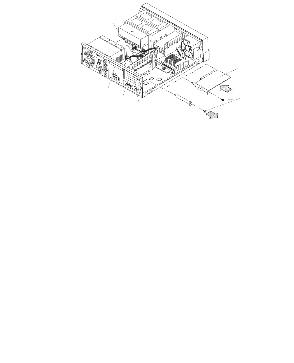
Maintaining PCI cards
Issue 3.3 February 2003 67
9. Add or remove the card as shown in the following figure.
10. Remove the ESD wrist strap.
11. Reattach the cover.
12. Reconnect the AC power cord.
13. Turn on all external SCSI devices starting with the device farthest from the system and
working toward the system.
14. Turn on the system monitor.
15. Turn on the system.
16. Press Stop+A simultaneously after the console banner is displayed, but before the
system starts booting.
17. Enter:
boot -r
This reboots the system so that it recognizes the new configuration.
18. Perform a CMSADM file system backup to back up the updated system configuration.
See your CMS software installation, maintenance, and troubleshooting document for
details.
PCI card
Screw
PCI slot 1
PCI slot 3
PCI slot 2
u5_pcicard.cdr
PC riser
board

Maintenance
68 Avaya CMS Sun Ultra 5 Computer Hardware Installation, Maintenance, and Troubleshooting
Replacing an UltraSCSI card with a SunSwift card
This section describes how to replace an UltraSCSI card with a SunSwift card. This is done
when the customer wants to add a second ethernet port.
Prerequisites
●Obtain a SunSwift PCI card.
●Obtain one or two 68-to-68 pin SCSI cables (comcode 407934470, part
number 595-4851-xx).
●Do a CMSADM backup.
●Turn off CMS before beginning this procedure.
Procedure
To replace an UltraSCSI card with a SunSwift card:
1. Enter:
/usr/sbin/shutdown -y -i0 -g0
This shuts down the system.
2. Turn off the system.
3. Turn off the system monitor.
4. Turn off all external SCSI devices starting with the device that is closest to the system
and working toward the farthest device.
!WARNING:
WARNING: You must wear an ESD wrist strap when installing or removing hardware
components to prevent electrical discharge that can damage the system.
5. Disconnect each 68-to-68 pin VHDCI cable from the UltraSCSI card and from the first
external device in each existing SCSI chain. There may be one chain of disk drives
and one chain of tape drives.
6. Remove the cover of the Ultra 5.
7. Disconnect the AC power cord.
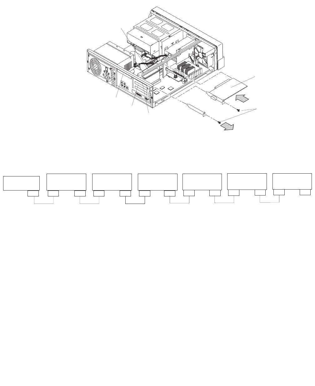
Maintaining PCI cards
Issue 3.3 February 2003 69
8. Remove the UltraSCSI card. It should be located in PCI slot 2.
9. Install the SunSwift card in PCI slot 2 (or wherever the UltraSCSI card was installed).
10. Reconfigure the SCSI devices in the order shown in the following figure.
PCI card
Screw
PCI slot 1
PCI slot 3
PCI slot 2
u5_pcicard.cdr
PC riser
board
SCSI
Connector
UniPack Disk
Drive 1
(optional)
UniPack Disk
Drive 2
(optional)
UniPack Disk
Drive 3
(optional)
UniPack Disk
Drive 4
(optional)
UniPack
Tape Drive 1
(required)
UniPack
Tape Drive 2
(optional)
WWW
WW W WA
WW
W
68-68 68-68 68-68 68-68 68-68
W = 68-68 pin SCSI cable
A = Auto-terminated
W
68-68
W
scsicble_swift.cdr
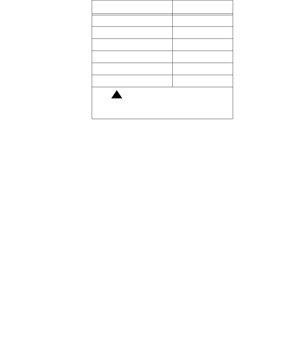
Maintenance
70 Avaya CMS Sun Ultra 5 Computer Hardware Installation, Maintenance, and Troubleshooting
SCSI devices are addressed as shown in the table below. These addresses are set
using the Target Address Switches on the back of each SCSI device.
11. Remove the ESD wrist strap.
12. Reattach the cover.
13. Reconnect the AC power cord.
14. Turn on all external SCSI devices starting with the device that is farthest from the
system and working toward the system.
15. Turn on the system monitor.
16. Turn on the system.
17. Press Stop+A simultaneously after the console banner is displayed, but before the
system starts booting.
18. Enter:
boot -r
This reboots the system so that it recognizes the new configuration.
19. Perform a CMSADM file system backup to back up the updated system configuration.
See your CMS software installation, maintenance, and troubleshooting document for
details.
Device Address
Disk Drive 1 0
Disk Drive 2 1
Disk Drive 3 2
Disk Drive 4 3
Tape Drive 1 4
Tape Drive 2 5
!Important:
!Important:
Important: Do not use a target address
greater than 5.
Maintaining PCI cards
Issue 3.3 February 2003 71
SAI/P cards
The Serial Asynchronous Interface/PCI (SAI/P) card connects terminals, printers and
modems to the computer. The computer can accommodate two SAI/P cards. Each SAI/P
card is associated with an external, 8-port expander box.
Identifying device entry names for ports on an SAI/P card
When the SAI/P card driver is installed, device entries are created to access the physical
ports on the expander box. The device name that is created is /dev/term/N, where N
represents SAI/P slot and expander box port entries. For example, when two SAI/P cards
are installed, the card in the lowest numbered slot is associated with physical ports
a000-a007, while ports for the second card are denoted by b000-b007.
To display the port designations for each SAI/P card, use the
/cms/toolsbin/display_ports command. A response similar to the following is
displayed:
Adding, moving, or removing an SAI/P card
This section describes how to add, remove or move an SAI/P card.
Adding an SAI/P card – To add an SAI/P card:
1. Identify the existing SAI/P cards installed in the system.
2. Verify that you have a recent CMSADM file system backup before you change card
configurations.
3. Enter:
/usr/sbin/shutdown -y -i0 -g0
This shuts down the system.
4. Turn off the system.
5. Turn off the system monitor.
6. Turn off all external SCSI devices starting with the device that is closest to the system
and working toward the farthest device.
7. Decide where you will install the new SAI/P card. Insert the SAI/P card into the Ultra 5.
See Installing or removing PCI cards on page 66 for more information.
8. Connect the expander box to the new SAI/P card.
/dev/term devices:a000 a001 a002 a003 a004 a005 a006 a007
#

Maintenance
72 Avaya CMS Sun Ultra 5 Computer Hardware Installation, Maintenance, and Troubleshooting
9. Turn on all external SCSI devices starting with the device that is farthest from the
system and working toward the system.
10. Turn on the system monitor.
11. Turn on the system.
12. Press Stop+A simultaneously after the console banner is displayed, but before the
system starts booting.
13. Enter:
boot -r
This reboots the system so that it recognizes the new configuration.
14. Enter the following commands:
sacadm -l
pmadm -l
These commands display existing administration information. Record this information
for later use.
15. Enter:
pmadm -r -p ttysaipslot -r ttyportdesignator
This removes port administration for all SAI/P cards, where slot indicates slot a or
slot b, and portdesignator is the full SAI/P port designation (a000, a001, and so
on).
16. Remove the SAI/P software drivers. Refer to Removing SAI/P drivers and utilities on
page 75.
17. Install the SAI/P software driver. See your CMS software installation, maintenance,
and troubleshooting document for details.
18. Administer all SAI/P ports cards.
19. Perform a CMSADM file system backup to back up the updated system configuration.
See your CMS software installation, maintenance, and troubleshooting document for
details.
Maintaining PCI cards
Issue 3.3 February 2003 73
Moving an SAI/P card – When moving SAI/P cards, remember to preserve the original
sequence of the cards. To do this, you many need to move more than one card. See
Identifying device entry names for ports on an SAI/P card on page 71 to determine the
ordering sequence.
To move an SAI/P card to a different PCI slot location.
1. Verify that you have a recent CMSADM file system backup before you change card
configurations.
2. Remove the SAI/P software drivers. Refer to Removing SAI/P drivers and utilities on
page 75.
3. Enter:
/usr/sbin/shutdown -y -i0 -g0
This shuts down the system.
4. Turn off the system.
5. Turn off the system monitor.
6. Turn off all external SCSI devices starting with the device that is closest to the system
and working toward the farthest device.
7. Remove the SAI/P card from the PCI slot.
8. Install the SAI/P card into a different PCI slot. See Installing or removing PCI cards on
page 66 for more information.
!
CAUTION:
CAUTION: Remember to preserve the original ordering sequence of the SAI/P cards.
9. Turn on all external SCSI devices starting with the device that is farthest from the
system and working toward the system.
10. Turn on the system monitor.
11. Turn on the system.
12. Press Stop+A simultaneously after the console banner is displayed, but before the
system starts booting.
13. Enter:
boot -r
This reboots the system so that it recognizes the new configuration.
14. Install the SAI/P software driver. See your CMS software installation, maintenance,
and troubleshooting document for details.
15. Perform a CMSADM file system backup to back up the updated system configuration.
See your CMS software installation, maintenance, and troubleshooting document for
details.

Maintenance
74 Avaya CMS Sun Ultra 5 Computer Hardware Installation, Maintenance, and Troubleshooting
Removing an SAI/P card – To remove an SAI/P card:
1. Verify that you have a recent CMSADM file system backup before you change card
configurations.
2. Enter the following commands:
sacadm -l
pmadm -l
These commands display existing administration information. Record this information
for later use.
3. Enter:
pmadm -r -p ttysaipslot -r ttyportdesignator
This removes port administration for all SAI/P cards, where slot indicates slot a or
slot b, and portdesignator is the full SAI/P port designation (a000, a001, and so
on).
4. Remove the SAI/P software drivers. Refer to Removing SAI/P drivers and utilities on
page 75.
5. Enter:
/usr/sbin/shutdown -y -i0 -g0
This shuts down the system.
6. Turn off the system.
7. Turn off the system monitor.
8. Turn off all external SCSI devices starting with the device that is closest to the system
and working toward the farthest device.
9. Remove the SAI/P card from the system. See Installing or removing PCI cards on
page 66 for more information.
10. Turn on all external SCSI devices starting with the device that is farthest from the
system and working toward the system.
11. Turn on the system monitor.
12. Turn on the system.
13. Press Stop+A simultaneously after the console banner is displayed, but before the
system starts booting.
14. Enter:
boot -r
This reboots the system so that it recognizes the new configuration.
15. Readminister all terminals, modems, and printers connected to the SAI/P expander
box.
Maintaining PCI cards
Issue 3.3 February 2003 75
16. Perform a CMSADM file system backup to back up the updated system configuration.
See your CMS software installation, maintenance, and troubleshooting document for
details.
Removing SAI/P drivers and utilities
To remove the SAI/P software drivers and utilities:
1. Enter:
pkgrm SUNWsaip
This removes the SAI/P software drivers. The following message is displayed:
2. Enter: y
This starts the removal of the SAI/P software driver. The following message is
displayed:
3. Enter: y
The following message is displayed:
If the removal is successful, the following message is displayed:
If removal is not successful, escalate through the normal channels.
# The following package is currently installed:
SUNWsaip Serial Asynchronous Interface Driver (PCI)
(sparc) X.0.0
Do you want to remove this package?
## Removing installed package instance <SUNWsaip>
This package contains scripts which will be executed with
super-user permission during the process of removing this
package.
Do you want to continue with the removal of this package [y,n,q,?]
## Verifying package dependencies.
## Processing package information.
## Executing preremove script.
Removal of <SUNWsaip> was successful.
#
Maintenance
76 Avaya CMS Sun Ultra 5 Computer Hardware Installation, Maintenance, and Troubleshooting
4. Enter:
pkgrm SUNWsaipu
This removes the SAI/P software utilities. The following message is displayed:
5. Enter: y
This starts the removal of the SAI/P software utilities. The following message is
displayed:
6. Enter: y
The following message is displayed:
If the removal is successful, the following message is displayed:
If removal is not successful, escalate through the normal channels.
# The following package is currently installed:
SUNWsaipu Serial Asynchronous Interface Utilities (PCI)
(sparc) X.0.0
Do you want to remove this package?
## Removing installed package instance <SUNWsaipu>
This package contains scripts which will be executed with
super-user permission during the process of removing this
package.
Do you want to continue with the removal of this package [y,n,q,?]
## Verifying package dependencies.
## Processing package information.
## Executing preremove script.
Removal of <SUNWsaipu> was successful.
#

Maintaining PCI cards
Issue 3.3 February 2003 77
Installing HSI/P cards
An HSI/P card supports X.25 switch links. For eight ACDS, two HSI/P cards and quad
cables are needed. If the system uses TCP/IP signaling for all ACDs, HSI/P cards are not
needed.
Note:
Note: Some CMS loads do not support the X.25 protocol. Contact the National
Customer Care Center or consult with your product distributor or
representative to verify if the X.25 protocol is supported on your CMS
system.
Installing HSI/P cards contains the following procedures:
●Replacing an HSI/P card on page 78
●Installing the first HSI/P card or a pair of HSI/P cards on page 78
●Installing HSI/P software and patches on page 79
●Setting up the switch link for each ACDon page 80
●Adding a second HSI/P card on page 81
If you are replacing a defective HSI/P card, see Replacing an HSI/P card on page 78. If
this is the initial installation of one or two HSI/P cards, start with Installing the first HSI/P
card or a pair of HSI/P cards. If a second HSI/P card is being added to a system already in
operation, see Adding a second HSI/P card on page 81.

Maintenance
78 Avaya CMS Sun Ultra 5 Computer Hardware Installation, Maintenance, and Troubleshooting
Replacing an HSI/P card
To replace an HSI/P card:
1. Log in to the system as root.
2. Enter:
/usr/sbin/shutdown -y -i0 -g0
This shuts down the system.
3. Press and hold the front panel power switch for 5 seconds to power off the system.
4. Turn off the system monitor.
5. Turn off all external SCSI devices, starting with the device that is closest to the system
and working toward the farthest device.
6. Disconnect the HSI/P quad cable connected to the card.
7. Remove and replace the defective HSI/P card. See Installing or removing PCI cards on
page 66 for detailed instructions.
8. Reattach the HSI/P quad cable.
9. Turn on all external SCSI devices, starting with the device that is farthest from the
system and working toward the system.
10. Turn on the system monitor.
11. Turn on the system.
Installing the first HSI/P card or a pair of HSI/P cards
To install the first HSI/P card or a pair of HSI/P cards:
1. Verify that you have a recent CMSADM file system backup before you change card
configurations.
2. Log in to the system as root.
3. Enter:
/usr/sbin/shutdown -y -i0 -g0
This shuts down the system.
4. Turn off the system.
5. Turn off the system monitor.
6. Turn off all external SCSI devices starting with the device that is closest to the system
and working toward the farthest device.
7. Install the HSI/P cards. See Installing or removing PCI cards on page 66 for more
information.

Maintaining PCI cards
Issue 3.3 February 2003 79
8. Attach the HSI/P quad cables, and connect the switch links to the quad cables by
following the instructions described in Avaya CMS Switch Connections, Administration,
and Troubleshooting, 585-215-876.
Note:
Note: Do not use serial port “A” to connect switch links when an HSI/P card is
installed. Serial port “A” is used only for single ACD installations. In a
multiple ACD arrangement, all switch links must be connected to an HSI/P
quad cable, to an ethernet port using TCP/IP, or a combination of HSI/P and
TCP/IP connections.
9. Turn on all external SCSI devices, starting with the device that is farthest from the
system and working toward the system.
10. Turn on the system monitor.
11. Turn on the system.
12. Press Stop+A simultaneously after the console banner is displayed, but before the
system starts booting.
The ok prompt is displayed.
13. Enter:
boot -r
This reboots the system so that it recognizes the new HSI/P cards.
Note:
Note: Sometimes the system fails to recognize a newly installed HSI card. If this
happens, the command show-devs does not show the HSI card and
/var/adm/messages fails to recognize the card upon bootup. See the
troubleshooting chapter of Avaya CMS Switch Connections, Administration,
and Troubleshooting, 585-215-876, for information about troubleshooting
HSI/P cards.
14. When the system comes back up, log in as root.
15. Continue with Installing HSI/P software and patches on page 79.
Installing HSI/P software and patches
Using the procedures in the CMS software installation, maintenance, and troubleshooting
document:
●Install the HSI/P software
●Reinstall the Solaris patches
After installing the software and patches, continue with Setting up the switch link for each
ACDon page 80.

Maintenance
80 Avaya CMS Sun Ultra 5 Computer Hardware Installation, Maintenance, and Troubleshooting
Setting up the switch link for each ACD
To change the switch link administration for each ACD:
1. Enter:
cmssvc
The CMS Services menu is displayed.
2. Select the run_cms option.
3. Turn off CMS.
4. Enter:
cmssvc
The CMS Services menu is displayed.
5. Select the swsetup option.
6. Select the ACD that you want to set up.
7. Accept the existing defaults for the following:
●Switch name
●Switch model (release)
●Vectoring
●Expert agent
●Central office disconnect supervision
●Local port
●Remote port
8. Select “X.25” and a specific link number when prompted for the link information.
9. Repeat Step 4 through 8 for each ACD that will use the HSI card.
10. Enter:
cmssvc
The CMS Services menu is displayed.
11. Select the run_cms option.
12. Turn on CMS.
13. Test and troubleshoot each switch connection using the procedures in Avaya CMS
Switch Connections, Administration, and Troubleshooting, 585-215-876.
14. Perform a CMSADM file system backup to back up the updated system configuration.
See your CMS software installation, maintenance, and troubleshooting document for
details.

Maintaining PCI cards
Issue 3.3 February 2003 81
Adding a second HSI/P card
Use the following procedures if you are adding a second HSI/P card to a system that is
already in operation. Before you do this procedure, verify that CMS is installed.
To add a second HSI/P card:
1. Verify that you have a recent CMSADM file system backup before you change card
configurations.
2. Log in to the system as root.
3. Enter:
/usr/sbin/shutdown -y -g0 -i0
This shuts down the system.
4. Turn off the system.
5. Turn off the system monitor.
6. Turn off all external SCSI devices starting with the device that is closest to the system
and working toward the farthest device.
7. Install the second HSI/P card. See Installing or removing PCI cards on page 66 for
more information.
8. Attach the HSI/P quad cable, and connect the switch links to the quad cable by
following the instructions described in Avaya CMS Switch Connections, Administration,
and Troubleshooting, 585-215-876.
Note:
Note: Do not use serial port “A” to connect switch links when an HSI/P card is
installed. Serial port “A” is used only for single ACD installations. In a
multiple ACD arrangement, all switch links must be connected to an HSI/P
quad cable, to an ethernet port using TCP/IP, or a combination of HSI/P and
TCP/IP connections.
9. Turn on all external SCSI devices starting with the device that is farthest from the
system and working toward the system.
10. Turn on the system monitor.
11. Turn on the system.
12. Press Stop+A simultaneously after the console banner is displayed, but before the
system starts booting.
13. Enter:
boot -r
This reboot the system so that it recognizes the new HSI/P card.

Maintenance
82 Avaya CMS Sun Ultra 5 Computer Hardware Installation, Maintenance, and Troubleshooting
Note:
Note: Sometimes the system fails to recognize a newly installed HSI card. If this
happens, the command show-devs does not show the HSI card and
/var/adm/messages fails to recognize the card upon bootup. See the
troubleshooting chapter of Avaya CMS Switch Connections, Administration,
and Troubleshooting, 585-215-876, for information about troubleshooting
HSI/P cards.
14. When the system comes back up, log in as root.
15. Administer the switch links as shown in Setting up the switch link for each ACDon
page 80.

Maintaining disk drives
Issue 3.3 February 2003 83
Maintaining disk drives
Overview
Procedures in this section include the following:
●Disk drive compatibility with CMS loads on page 83
●Prerequisites on page 83
●Required references on page 84
●Replacing the primary internal EIDE boot disk drive on page 85
●Adding or replacing the internal EIDE data disk drive on page 93
●Adding or replacing external SCSI disk drives on page 102
●Setting up the disk drives on page 110.
●Partitioning disk drives on page 111
●Administering data disk drives on page 121
Disk drive compatibility with CMS loads
When a new or replacement disk drive is installed in an older system, the CMS load may
not be compatible with the disk drive if the CMS configuration files have not been updated.
These configuration files (/olds/disk.conf and /olds/olds-funcs) must be edited
or replaced with the correct information. Contact the Avaya technical support organization
for assistance.
Prerequisites
Do a CMSADM backup, if possible, before you add or replace a disk drive. See your CMS
software installation, maintenance, and troubleshooting document for this procedure.
Before you attempt to replace defective data (nonboot) disks, try to print the current setup
for all ACDs. This information must be readministered after you install replacement disks.

Maintenance
84 Avaya CMS Sun Ultra 5 Computer Hardware Installation, Maintenance, and Troubleshooting
Required references
The following references are required when doing procedures in this section:
●Avaya CMS R3V11 Software Installation, Maintenance, and Troubleshooting,
585-215-115
●Avaya CMS R3V9 Software Installation, Maintenance, and Troubleshooting,
585-215-956
●Avaya CMS R3V8 Software Installation, Maintenance, and Troubleshooting,
585-210-941
●Avaya CMS Software Installation and Setup (R3V5 and R3V6), 585-215-866
●Sun Ultra 5 Service Manual
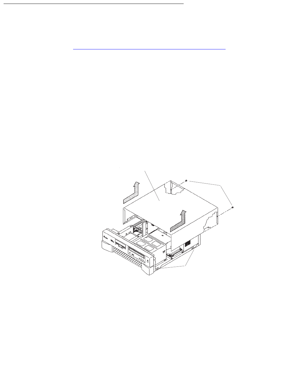
Maintaining disk drives
Issue 3.3 February 2003 85
Replacing the primary internal EIDE boot disk drive
This procedure describes how to replace the primary internal EIDE boot disk drive. If you
are also adding or replacing the secondary data disk drive, use these procedures in
concert with Adding or replacing the internal EIDE data disk drive on page 93 while you
have the computer open.
Opening the computer
To open the computer:
1. If you have not already done so, use the following command to shut down the
computer:
/usr/sbin/shutdown -y -i0 -g0
2. Turn off the power to the computer.
3. Remove the two screws on the back of the unit that secure the cover to the chassis.
See the following figure.
4. Slide the cover back 1 or 2 inches and lift it up away from the chassis.
5. Place the cover in a convenient location so that it does not interfere with your work.
Cover Tabs
Cover
Screws
u5
_
remove
_
cover.cdr

Maintenance
86 Avaya CMS Sun Ultra 5 Computer Hardware Installation, Maintenance, and Troubleshooting
6. Attach an antistatic wrist strap to the metal chassis of the computer and to your wrist.
See the following figure.
7. Disconnect the AC power cord.
!Important:
!Important:
Important: If the computer has a PCI card in slot position 2, you must remove that card
during this procedure to make it easier to reach the components. To remove
PCI card 2, you must first remove the PCI card 2 screw. On the Series 1
computers, this screw is on the back of the computer. On Series 2 and later
computers, this screw is on the top of the frame above the PCI card.
u5_wriststrap.cdr
PCI slot 2
screws
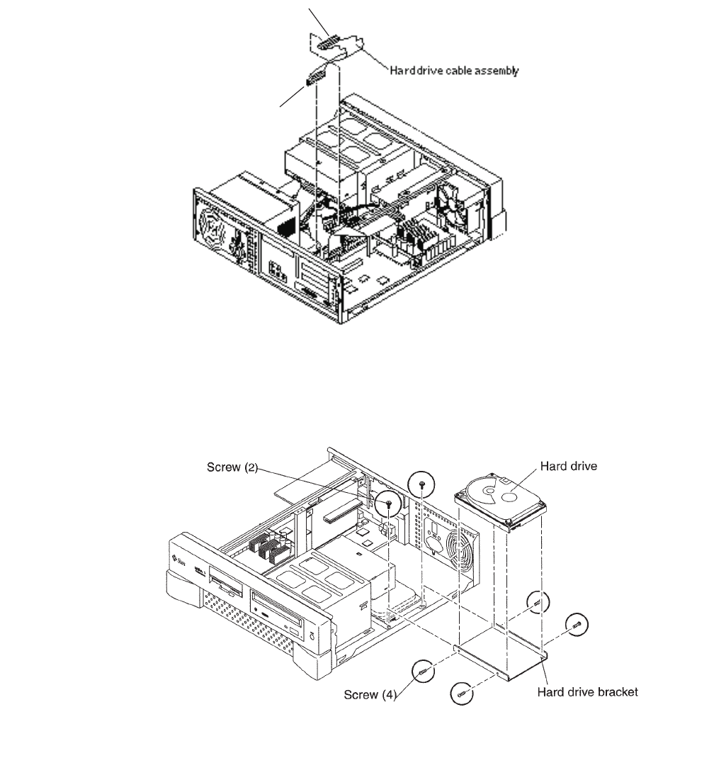
Maintaining disk drives
Issue 3.3 February 2003 87
Removing the primary internal boot disk drive
To remove the primary internal boot disk drive:
1. Disconnect the EIDE ribbon cable from the motherboard. Remember where the EIDE
ribbon cable connects to the motherboard. The following figure shows an EIDE cable
when there is only one internal disk drive.
2. If the computer has a secondary data disk drive installed, disconnect the EIDE ribbon
cable from the secondary disk drive. If no secondary disk is installed, skip this step.
3. Remove the two screws that secure the primary disk drive mounting bracket assembly
to the chassis. See the following figure.
orig_ide_cable.cdr
MOTHER BOARD
DRIVE
u5_master_install.cdr
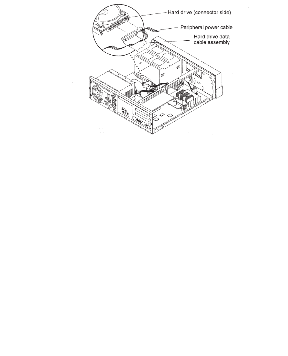
Maintenance
88 Avaya CMS Sun Ultra 5 Computer Hardware Installation, Maintenance, and Troubleshooting
4. Disconnect the power cable from the primary disk drive. See the following figure.
5. Remove the primary disk drive and mounting bracket assembly from the computer.
6. Disconnect the EIDE ribbon cable from the primary disk drive. Save this EIDE cable in
case you have to reinstall the old disk drive.
7. Remove the four screws that hold the primary disk drive to the mounting bracket. Save
the screws and mounting bracket for the new primary disk drive. Label the disk drive
“Original Master Disk,” and save it in case you have to reinstall the original
configuration.
u5_master_cable.cdr
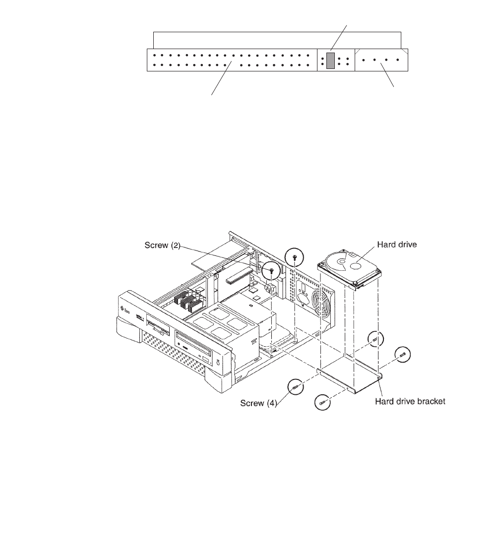
Maintaining disk drives
Issue 3.3 February 2003 89
Installing the new primary internal disk drive
To install the new primary internal disk drive:
1. Ensure that the jumpers on the primary internal hard drive are set to the Cable Select
(CS) setting. See the following figure.
2. Using the original mounting bracket, attach the new primary disk drive labeled “Master
Disk” to the mounting bracket using the four screws from the new disk drive kit. The
mounting bracket that came with the new primary disk drive can be discarded.
Tip:
Tip: Install each screw with just a few turns before you tighten all four screws.
3. With the new primary internal disk drive you will receive new EIDE ribbon cables. Use
the cable that has three connectors (SLAVE, MASTER, and MOTHERBOARD).
Connect the end labeled MASTER to the connector on the rear of the new primary
internal disk drive.
4. Connect the power cable to the primary internal disk drive.
EIDE ribbon
cable connector
Jumper in
Cable Select (CS)
position
Power
connector
cable_sel.cdr
u5_master_install.cdr
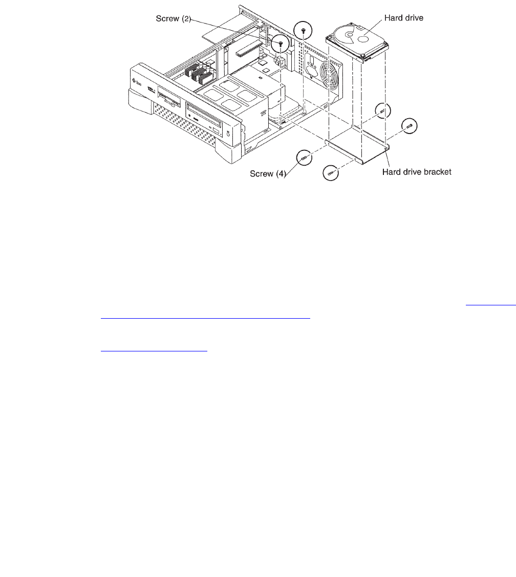
Maintenance
90 Avaya CMS Sun Ultra 5 Computer Hardware Installation, Maintenance, and Troubleshooting
5. Slide the mounting bracket into place, routing the EIDE ribbon cable so that the
MOTHER BOARD connector can reach the connector on the motherboard, and the
SLAVE connector can reach the secondary internal disk drive.
6. Attach the mounting bracket to the chassis using the two screws saved earlier. See the
following figure.
7. Connect the EIDE ribbon cable end labeled MOTHER BOARD to the EIDE connector
on the mother board.
Tip:
Tip: If you are also replacing the secondary internal data disk drive, wait and
attach the EIDE ribbon cable to the mother board after you install that drive.
8. Do one of the following:
●If you are adding or replacing the secondary data disk drive, continue with Adding or
replacing the internal EIDE data disk drive on page 93.
●If you are not adding or replacing the secondary data disk drive, continue with
Closing the computer on page 91.
u5_master_install.cdr

Maintaining disk drives
Issue 3.3 February 2003 91
Closing the computer
If you are also replacing the secondary internal data disk drive, do not close the computer.
Continue with Adding or replacing the internal EIDE data disk drive on page 93.
To close the computer:
1. If you removed the PCI card from Slot 2 earlier, reinstall it now.
2. Reconnect the AC power cord to the computer.
3. Detach the ESD wrist strap.
4. Replace the cover on the computer. Slide the cover forward until it fits snugly around
the chassis.
5. Replace the two cover screws.
Tip:
Tip: Install each screw with just a few turns before you tighten both screws.
6. Do one of the following:
●If you are adding or replacing external SCSI disk drives, continue with Adding or
replacing external SCSI disk drives on page 102.
●If you are not adding or replacing external SCSI disk drives, continue with Turning
on the system on page 92.

Maintenance
92 Avaya CMS Sun Ultra 5 Computer Hardware Installation, Maintenance, and Troubleshooting
Turning on the system
To turn on the system:
1. Turn on all external SCSI devices starting with the device that is farthest from the
system and working toward the system.
2. Turn on the system monitor.
3. Turn on the system.
4. Press Stop+A simultaneously after the console banner is displayed, but before the
system starts booting.
5. Enter the following commands:
setenv auto-boot? false
reset-all
This resets the system and the ok prompt is displayed.
6. Enter:
probe-ide
This checks to see that the system recognizes the new disk drive. If the new drive is
not listed, check for a secure connection between the motherboard and the new drive.
7. Reboot the system by entering the following commands:
!
CAUTION:
CAUTION: If you fail to enter these commands, any reboots that you do in the future will
stop at the boot prompt instead of proceeding through the normal boot-up
process.
setenv auto-boot? true
boot -r
8. Continue with Setting up the disk drives on page 110.

Maintaining disk drives
Issue 3.3 February 2003 93
Adding or replacing the internal EIDE data disk drive
This section describes how to add or replace the internal EIDE data disk drive in the Ultra 5
computer. The optional drive, together with hardware and a new ribbon cable, is packaged
separately from the Ultra 5 computer.
Note:
Note: In the following procedures, the disk drive that is already installed in the
Ultra 5 computer is referred to as the primary drive, and the new drive that
you install is referred to as the secondary drive.
Unpacking the disk drive
Remove the following items from the box that contains the secondary data disk drive and
place them in a convenient location:
●EIDE disk drive
●Mounting bracket
●Four pan head screws
●New EIDE ribbon cable
The new disk drive comes with two ribbon cables. The cable used with the Ultra 5 has
three connectors labeled SLAVE, MASTER, and MOTHERBOARD. The other cable
may be discarded.
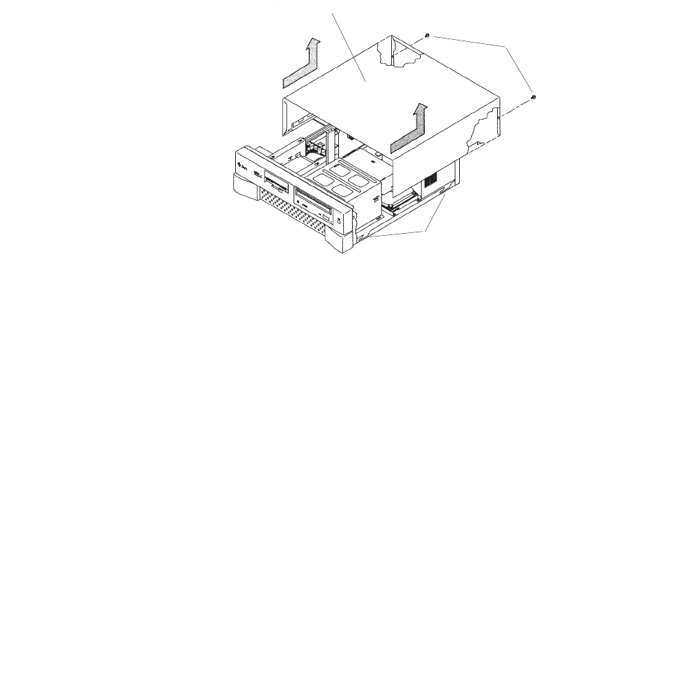
Maintenance
94 Avaya CMS Sun Ultra 5 Computer Hardware Installation, Maintenance, and Troubleshooting
Opening the computer
To open the computer:
1. If you have not already done so, use the following command to shut down the
computer:
/usr/sbin/shutdown -y -i0 -g0
2. Turn off the power to the computer.
3. Remove the two screws on the back of the unit that secure the cover to the chassis.
See the following figure.
4. Slide the cover back 1 or 2 inches and lift it up away from the chassis.
5. Place the cover in a convenient location so that it does not interfere with your work.
Cover Tabs
Cover
Screws
u5
_
remove
_
cover.cdr

Maintaining disk drives
Issue 3.3 February 2003 95
6. Attach an antistatic wrist strap to the metal chassis of the computer and to your
wrist.See the following figure.
7. Disconnect the AC power cord.
!Important:
!Important:
Important: If the computer has a PCI card in slot position 2, you may want to remove
that card during this procedure to make it easier to reach the components.
To remove PCI card 2, you must first remove the PCI card 2 screw. On the
Series 1 computers, this screw is on the back of the computer. On Series 2
and later computers, this screw is on the top of the frame above the PCI
card.
u5_wriststrap.cdr
PCI slot 2
screws

Maintenance
96 Avaya CMS Sun Ultra 5 Computer Hardware Installation, Maintenance, and Troubleshooting
Removing the secondary internal disk drive
If there is no secondary internal disk drive, continue with Removing the diskette drive on
page 97.
To remove the secondary internal data disk drive:
1. Loosen, but do not remove, the three screws that secure the mounting bracket for the
secondary internal disk drive to the top of the chassis frame. See the following figure.
2. Remove the disk drive bracket from the chassis by sliding it back and lifting it free of
the three screws.
3. Disconnect the power cable from the secondary disk drive.
4. Lift out the mounting bracket and the attached disk drive.
5. Remove the four screws that hold the secondary internal disk drive to the mounting
bracket. Save the screws and mounting bracket for the new secondary internal disk
drive. Label the disk drive “Slave Disk,” and save it in case you have to reinstall the
original configuration.
Screw (4)
Secondary
disk drive
Screw (3)
u5_second_disk.cdr
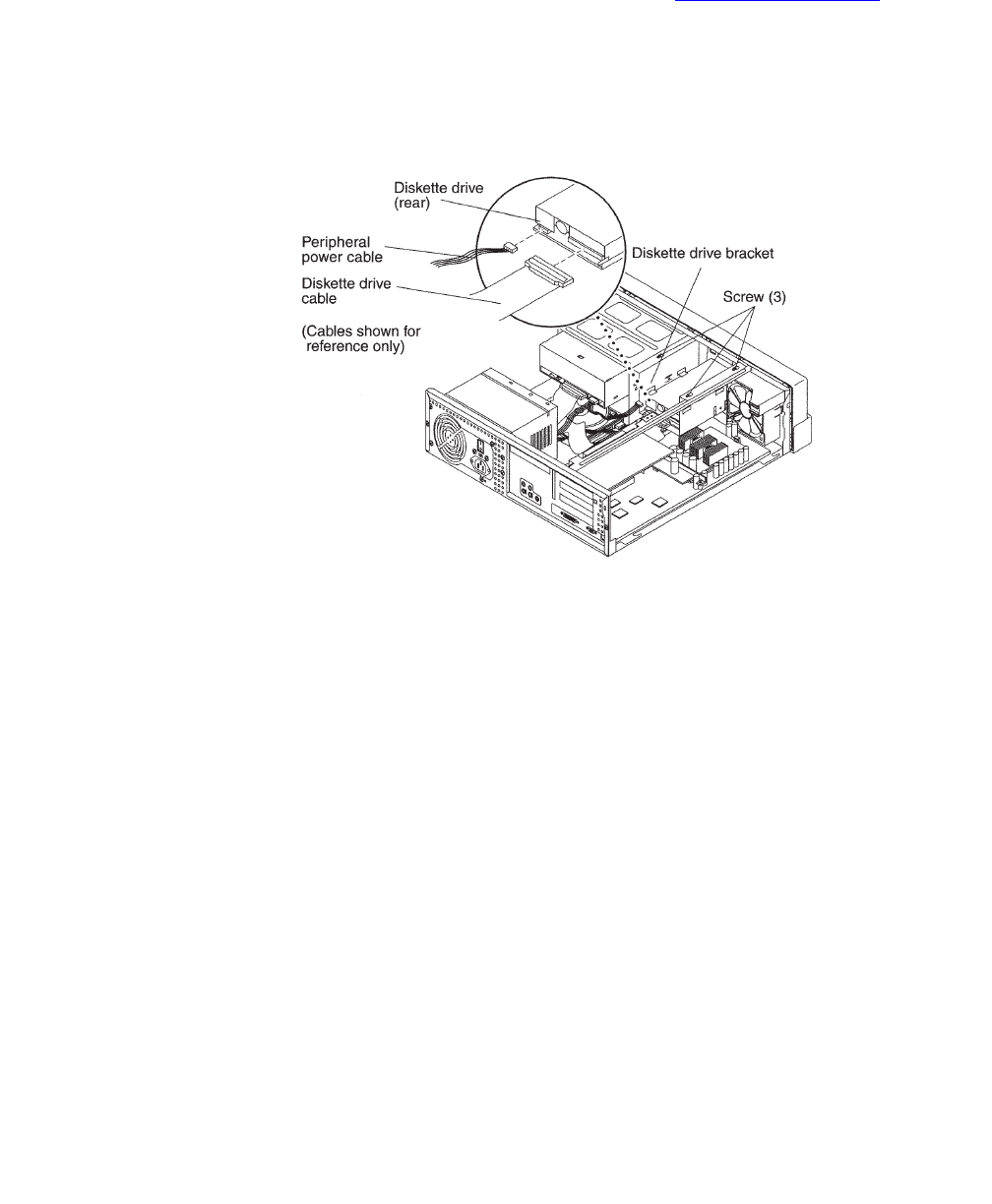
Maintaining disk drives
Issue 3.3 February 2003 97
Removing the diskette drive
If there is no 3.5-inch internal diskette drive, continue with Installing new cabling on
page 98.
To remove the diskette drive:
1. Disconnect the power cable and diskette drive cable from the rear of the diskette drive.
See the following figure.
2. Loosen but do not remove the three screws that secure the diskette drive mounting
bracket to the top of the chassis frame.
3. Remove the diskette drive bracket from the chassis by sliding it back and lifting it free
of the three screws.
4. Lift out the mounting bracket and attached diskette drive.
5. At the motherboard, disconnect the diskette drive cable that comes from the diskette
drive.
6. Save the diskette drive and diskette drive cable in case you have to reinstall the
original configuration.
u5_diskette_cabling.cdr

Maintenance
98 Avaya CMS Sun Ultra 5 Computer Hardware Installation, Maintenance, and Troubleshooting
Installing new cabling
If the primary boot disk drive already has a new EIDE ribbon cable, continue with Installing
the secondary disk drive on page 99.
To install new cabling:
1. Remove the ribbon cable from the back of the primary disk drive. You may need to
remove the primary disk drive by removing the two screws securing the primary disk
drive bracket and lifting out the drive. See the following figure.
2. Remove the other end of this cable from the motherboard. Remember the slot in the
motherboard from which you remove this connector. You will install another connector
in this slot in the next step.
3. On the new ribbon cable that was supplied with the secondary disk drive, there are
three connectors labeled MOTHERBOARD, MASTER, and SLAVE. Insert the
connector labeled MOTHERBOARD into the slot in the motherboard from which you
removed a connector in the previous step. See the following figure.
4. Connect the connector labeled MASTER to the primary disk drive.
5. If you previously removed the primary disk drive, reinstall it on the chassis.
u5_master_cable.cdr

Maintaining disk drives
Issue 3.3 February 2003 99
Installing the secondary disk drive
To install the new secondary internal disk drive:
1. Ensure that the jumpers on the secondary internal hard drive are set to the Cable
Select (CS) setting. See the following figure.
2. Attach the secondary internal disk drive to the new mounting bracket with the four
screws from the old disk drive or from the new disk drive kit. Arrange the drive so that
the connectors point to the back of the computer.
Tip:
Tip: Install each screw with just a few turns before you tighten all four screws.
3. Connect the EIDE ribbon cable connector labeled SLAVE to the secondary internal
disk drive.
EIDE ribbon
cable connector
Jumper in
Cable Select (CS)
position
Power
connector
cable_sel.cdr
Screw (4)
Secondary
disk drive
Screw (3)
u5_second_disk.cdr

Maintenance
100 Avaya CMS Sun Ultra 5 Computer Hardware Installation, Maintenance, and Troubleshooting
4. Connect the power cable to the secondary internal disk drive.
5. Install the mounting bracket for the secondary internal disk drive to the frame of the
chassis, slipping the three holes in the mounting bracket over the three screws in the
chassis frame.
6. Slide the mounting bracket forward as far as possible.
7. Tighten the three screws.
8. Route the cables to provide clearance.
Closing the computer
To close the computer:
1. If you removed the PCI card from Slot 2 earlier, reinstall it now.
2. Reconnect the AC power cord to the computer.
3. Detach the ESD wrist strap.
4. Replace the cover on the computer. Slide the cover forward until it fits snugly around
the chassis.
5. Replace the two cover screws.
Tip:
Tip: Install each screw with just a few turns before you tighten both screws.
6. Do one of the following:
●If you are adding or replacing any external SCSI disk drives, continue with Adding or
replacing external SCSI disk drives on page 102.
●If you are not adding or replacing any external SCSI disk drives, continue with
Turning on the system on page 101.

Maintaining disk drives
Issue 3.3 February 2003 101
Turning on the system
If you are also adding or replacing secondary external disk drives, do not power-up the
system. Continue with Adding or replacing external SCSI disk drives on page 102.
To turn on the system:
1. Turn on all external SCSI devices starting with the device that is farthest from the
system and working toward the system.
2. Turn on the system monitor.
3. Turn on the system.
4. Press Stop+A simultaneously after the console banner is displayed, but before the
system starts booting.
5. Enter the following commands:
setenv auto-boot? false
reset-all
This resets the system and the ok prompt is displayed.
6. Enter:
probe-ide
This checks to see that the system recognizes the new disk drives. If the new drives
are not listed, make sure there is a secure connection between the motherboard and
the new drives.
7. Reboot the system by entering the following commands:
!
CAUTION:
CAUTION: If you fail to enter these commands, any reboots that you do in the future will
stop at the boot prompt instead of proceeding through the normal boot-up
process.
setenv auto-boot? true
boot -r
The system reboots.
8. Continue with Setting up the disk drives on page 110.

Maintenance
102 Avaya CMS Sun Ultra 5 Computer Hardware Installation, Maintenance, and Troubleshooting
Adding or replacing external SCSI disk drives
This section describes how to add or replace an external SCSI disk drive on an existing
system.
Adding or replacing a disk drive
To add or replace an external disk drive:
1. Log in to the system as root.
2. Enter:
/usr/sbin/shutdown -y -i0 -g0
The system shuts down and displays the ok prompt.
3. Turn off the system.
4. Turn off the system monitor.
5. Turn off all external SCSI devices starting with the device that is closest to the system
and working toward the farthest device.
6. Connect the disk drive to the other SCSI devices. See SunSwift connections on
page 103 or UltraSCSI connections on page 105.
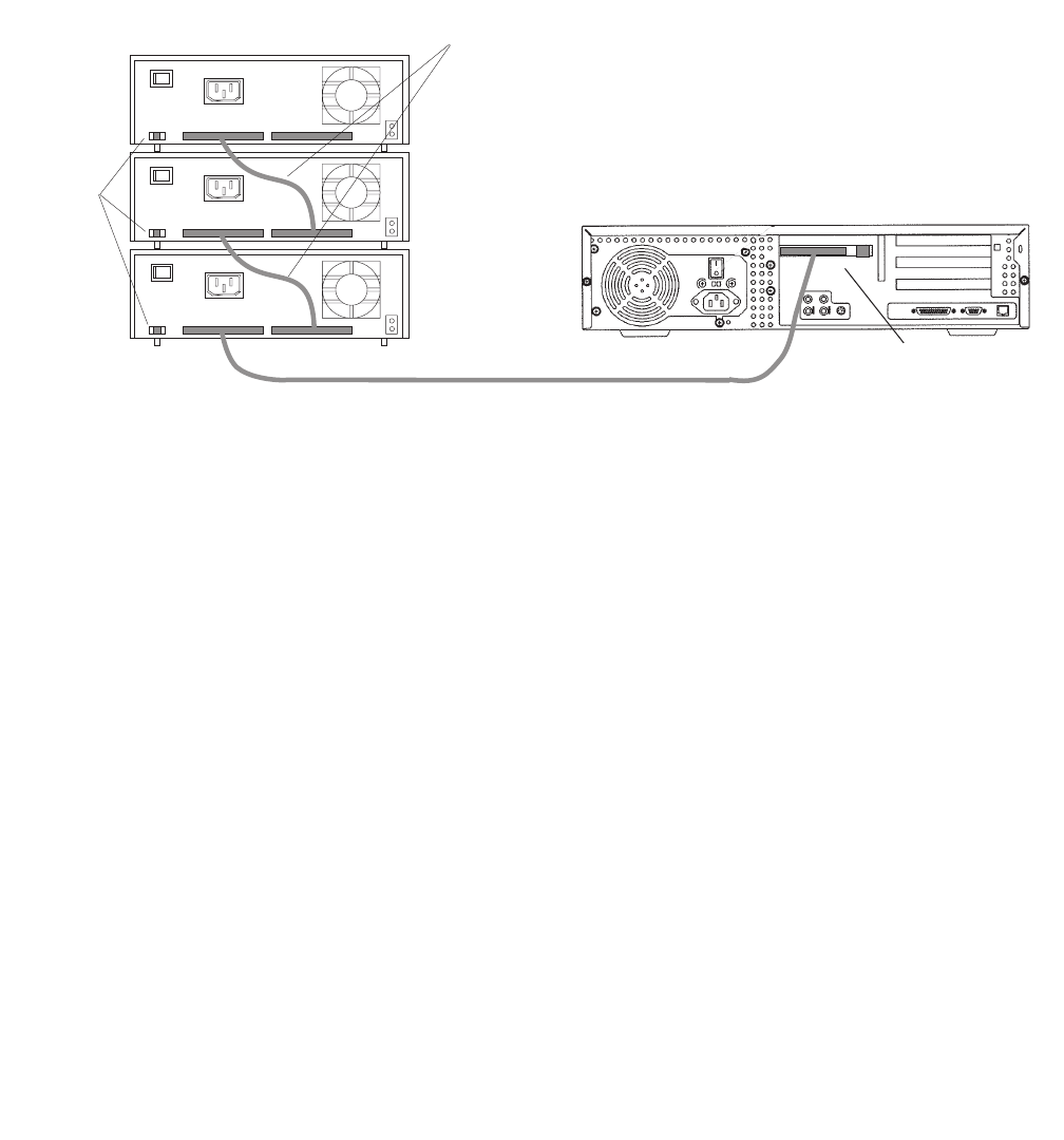
Maintaining disk drives
Issue 3.3 February 2003 103
SunSwift connections – The following figure shows how to connect UniPack SCSI disk
drives and tape drives to a SunSwift card. A 68-to-68-pin SCSI cable connects from the
SunSwift PCI card on the back of the computer to the IN connector on the back of the SCSI
device that is closest to the computer. If you have more than one SunSwift card, connect
the drives to the card in the lowest slot number. A 68-to-68 pin SCSI cable connects from
the OUT connector of that device to the IN connector of the next device. Continue this
process until all assigned devices are connected in the SCSI chain.
.
When connecting SCSI devices, the last device in the chain MUST be terminated, either
via an auto-terminated device or with a manual terminator.
When using an auto-terminated SCSI device, you do not need to connect a SCSI
terminator to the OUT connector of the last SCSI device in the chain. To verify that the last
device is auto-terminated, check the LEDs labeled Auto Term High and Auto Term Low on
the back panel of the device. In a CMS configuration, both LEDs are lit on the last device in
the SCSI chain. If a device in the SCSI chain is not the last device, neither termination LED
is lit.
When using a manually-terminated device, you must connect a SCSI terminator to the
OUT connector of the last SCSI device in the chain. When you connect the SCSI
terminator to the OUT connector, the LED on the terminator is lit.
Stack of three
external SCSI devices
SunSwift card
in PCI slot 2
Back panel of Ultra 5
IN
IN
IN
OUT
OUT
OUT
68-to-68 pin SCSI cable
Target
address
switch
68-to-68 pin SCSI cable
scsi_sunswift.cdr
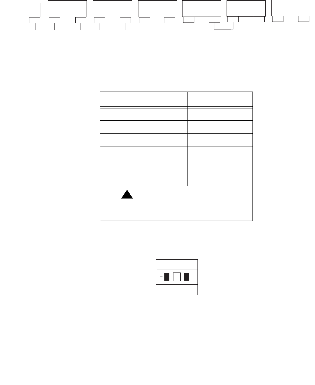
Maintenance
104 Avaya CMS Sun Ultra 5 Computer Hardware Installation, Maintenance, and Troubleshooting
The following figure shows the SCSI cabling for a SunSwift card.
SCSI devices are addressed as shown in the following table.
The addresses are set using the target address switches on the back of each SCSI device.
Before setting the target address, make sure that the power is off on the SCSI devices.
SCSI
Connector
UniPack Disk
Drive 1
(optional)
UniPack Disk
Drive 2
(optional)
UniPack Disk
Drive 3
(optional)
UniPack Disk
Drive 4
(optional)
UniPack
Tape Drive 1
(required)
UniPack
Tape Drive 2
(optional)
WWW
WW W WA
WW
W
68-68 68-68 68-68 68-68 68-68
W = 68-68 pin SCSI cable
A = Auto-terminated
W
68-68
W
scsicble_swift.cdr
Device Address
Disk drive 1 0
Disk drive 2 1
Disk drive 3 2
Disk drive 4 3
Tape drive 1 4
Tape drive 2 5
!Important:
!Important:
Important: Do not use a target address
greater than 5.
Press this side to increase
the address number.
Press this side to decrease
the address number.
+
2
scsiidsw.cdr
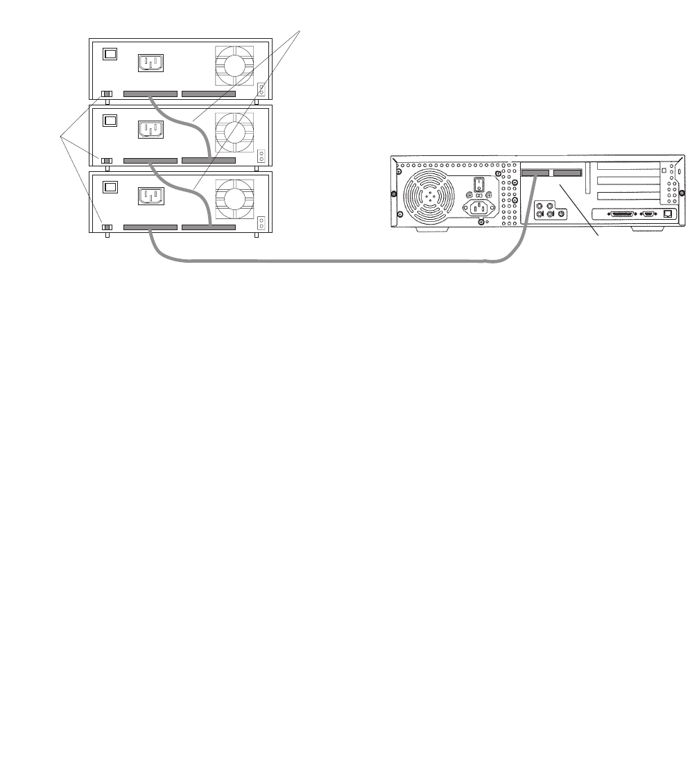
Maintaining disk drives
Issue 3.3 February 2003 105
UltraSCSI connections – The following figure shows how to connect UniPack SCSI disk
drives and tape drives to an UltraSCSI card. A 68-to-68-pin VHDCI SCSI cable connects
from the UltraSCSI PCI card on the back of the computer to the IN connector on the back
of the SCSI device that is closest to the computer. A 68-to-68 pin SCSI cable connects
from the OUT connector of that device to the IN connector of the next device. Continue this
process until all assigned devices are connected in the SCSI chain.
When connecting SCSI devices, the last device in the chain MUST be terminated, either
via an auto-terminated device or with a manual terminator.
When using an auto-terminated SCSI device, you do not need to connect a SCSI
terminator to the OUT connector of the last SCSI device in the chain. To verify that the last
device is auto-terminated, check the LEDs labeled Auto Term High and Auto Term Low on
the back panel of the device. In a CMS configuration, both LEDs are lit on the last device in
the SCSI chain. If a device in the SCSI chain is not the last device, neither termination LED
is lit.
When using a manually-terminated device, you must connect a SCSI terminator to the
OUT connector of the last SCSI device in the chain. When you connect the SCSI
terminator to the OUT connector, the LED on the terminator is lit.
68-to-68 pin VHDCI cable
Stack of three
external SCSI devices
Dual-channel
UltraSCSI card in PCI slot 2
IN
IN
IN
OUT
OUT
OUT
68-to-68 pin SCSI cable
Target
address
switch
Back panel of Ultra 5
scsiuni.cdr
(left) (right)

Maintenance
106 Avaya CMS Sun Ultra 5 Computer Hardware Installation, Maintenance, and Troubleshooting
The following figure shows the SCSI cabling schemes that are possible with an UltraSCSI
card that is installed in slot 2 of an Ultra 5 computer.
Note:
Note: The “Left/Right” designations shown above are based on the UltraSCSI card
being installed in slot 2. If the UltraSCSI card is installed in slots 1 or 3,
connect the disk drives to the right connector and the tape drives to the left
connector.
Left SCSI
Connector
Right SCSI
Connector
UniPack Disk
Drive 1
(optional)
UniPack Disk
Drive 2
(optional)
UniPack Disk
Drive 3
(optional)
UniPack Disk
Drive 4
(optional)
UniPack
Tape Drive 1
(required)
UniPack
Tape Drive 2
(optional)
VV
VV
W W W A
A
W
W W
68-68
68-68
68-68 68-68
68-68
V = 68-68 pin VHDCI cable
W = 68-68 pin SCSI cable
A = Auto-terminated
W
68-68
W
scsicble.cdr
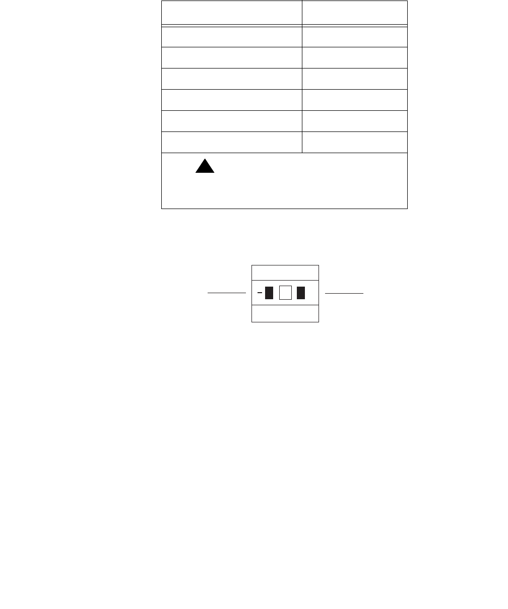
Maintaining disk drives
Issue 3.3 February 2003 107
SCSI devices are addressed as shown in the following table.
The addresses are set using the target address switches on the back of each SCSI device.
Before setting the target address, make sure that the power is off on the SCSI devices.
Device Address
Disk drive 1 0
Disk drive 2 1
Disk drive 3 2
Disk drive 4 3
Tape drive 1 4
Tape drive 2 5
!Important:
!Important:
Important: Do not use a target address
greater than 5.
Press this side to increase
the address number.
Press this side to decrease
the address number.
+
2
scsiidsw.cdr

Maintenance
108 Avaya CMS Sun Ultra 5 Computer Hardware Installation, Maintenance, and Troubleshooting
Turning on the system
To turn on the system:
1. Connect the power cord from the disk drive to a power source.
2. Turn on all external SCSI devices starting with the device that is farthest from the
system and working toward the system.
Note:
Note: For most SCSI devices, the power LED will light as soon as you power-on
the device. For some disk drives, the power LED will not light until the
system begins POST.
3. Turn on the system monitor.
4. Turn on the system.
5. Press Stop+A simultaneously after the console banner is displayed, but before the
system starts booting.
6. Enter the following commands:
setenv auto-boot? false
reset-all
This resets the system and the ok prompt is displayed.
7. Enter:
probe-scsi-all
This checks to see that the system recognizes the new external disk drives. The
resulting display should list the new drives as Target 0-3. If the new drives are not
listed, make sure there is a secure connection between the SCSI port and the new
drives.
8. Enter:
reset-all
This resets the system and the ok prompt is displayed.
9. Enter:
probe-ide
This checks to see that the system recognizes the new internal EIDE disk drives. If the
new drives are not listed, make sure there is a secure connection between the
motherboard and the new drives.

Maintaining disk drives
Issue 3.3 February 2003 109
10. Reboot the system by entering the following commands:
!
CAUTION:
CAUTION: If you fail to enter these commands, any reboots that you do in the future will
stop at the boot prompt instead of proceeding through the normal boot-up
process.
setenv auto-boot? true
boot -r
The system reboots.
11. Continue with Setting up the disk drives on page 110.
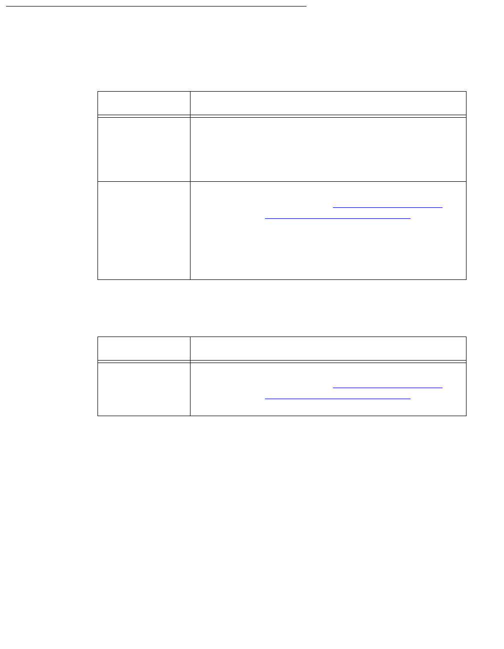
Maintenance
110 Avaya CMS Sun Ultra 5 Computer Hardware Installation, Maintenance, and Troubleshooting
Setting up the disk drives
After you replace defective disk drives, do one of the following:
After you add new disk drives, do the following:
Drive replaced Procedure
Boot disk Continue with the procedures in “Performing a
CMSADM restore procedure of a mirrored or
non mirrored system” in the maintenance chapter of
the software installation, maintenance, and
troubleshooting document for your version of CMS.
Data disk Partition and administer the drive so that it works with
the existing disk drives (see Partitioning disk drives on
page 111 and Administering data disk drives on
page 121). Continue with the procedures in
“Recovering a nonmirrored system after data disk
failure” in the Maintenance chapter of the software
installation, maintenance, and troubleshooting
document for your version of CMS.
Drive added Procedure
Data disk Partition and administer the drive so that it works with
the existing disk drives (see Partitioning disk drives on
page 111 and Administering data disk drives on
page 121).

Maintaining disk drives
Issue 3.3 February 2003 111
Partitioning disk drives
Requirements for partitioning data disk drives differs for the releases of CMS.
R3V9 and later
If you are adding new disk drives to a system where CMS is operational, partitioning is
done automatically using CMS commands. Skip manual partitioning and continue with
Administering data disk drives on page 121.
If you are replacing a defective disk drive in a system and CMS is not operational or if you
are replacing a defective boot disk, you must manually partition the disk drive. Use the
following information:
●Disk partition values, R3V11 boot disks on page 112, R3V9 boot disks on page 112, or
R3V9 and later data disks on page 113
●Partitioning and formatting a disk on page 117
R3V8 and earlier
For R3V8 and earlier systems, you must partition and format the new or replacement disk
drives. Use the following information:
●Disk partition values, R3V8 and earlier data disks on page 115
●Partitioning and formatting a disk on page 117
Disk partition values
During the disk partitioning procedure, you must enter the size of each partition. Since disk
models change often, see the software installation, maintenance, and troubleshooting
document for your current CMS release to verify the correct disk partitioning values.
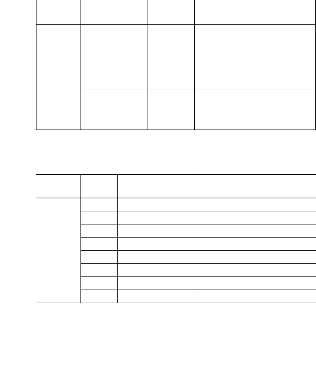
Maintenance
112 Avaya CMS Sun Ultra 5 Computer Hardware Installation, Maintenance, and Troubleshooting
R3V11 boot disks – The following table lists the boot disk drives that are currently
supported for R3V11. These partition sizes are entered in Gigabytes (gb).
R3V9 boot disks – The following table lists the boot disk drives that are currently
supported for R3V9. These partition sizes are entered in gigabytes (gb) and cylinders (c).
Disk Partition ID tag Permission
flag Starting cylinder Value
20-GB IDE 0 root wm 0 4gb
1 swap wu 8323 1gb
2 backup wm Use the default values for partition 2.
3 un wm 10404 3gb
4 un wm 16646 2gb
5-7 un wm Do not enter a value for partitions 5
through 7. These values are
populated automatically when the
boot disks resynchronize during the
restore procedure.
Disk Partition ID tag Permission
flag Starting cylinder Value
20-GB IDE 0 root wm 0 4gb
1 swap wu 8323 1gb
2 backup wm Use the default values for partition 2.
3 un wm 10404 3gb
4 un wm 16646 2gb
5 un wm 20808 2gb
6 un wm 24970 2gb
7 un wm 29132 9658c
Maintaining disk drives
Issue 3.3 February 2003 113
R3V9 and later data disks – The following table lists the data disk drives that are
currently supported for R3V9 and later. These partition sizes are entered in gigabytes (gb)
and cylinders (c).
Disk Partition ID tag Permission
flag Starting cylinder Value
36-GB
SCSI
0 un wm 0 2gb
1 un wm 1452 2gb
21backup wm Do not enter a value for partition 2.
3 un wm 2904 2gb
4 un wm 4356 2gb
5 un wm 5808 2gb
6 un wm 7260 2gb
7 un wm 8712 15908c
20-GB
IDE
0 un wm 0 2gb
1 un wm 4162 2gb
21backup wm Do not enter a value for partition 2.
3 un wm 8324 2gb
4 un wm 12486 2gb
5 un wm 16648 2gb
6 un wm 20810 2gb
7 un wm 24972 13818c
18-GB
SCSI
0 un wm 0 2gb
1 un wm 891 2gb
21backup wm Do not enter a value for partition 2.
3 un wm 1782 2gb
4 un wm 2673 2gb
5 un wm 3564 2gb
6 un wm 4455 2gb
7 un wm 5346 2160c
Maintenance
114 Avaya CMS Sun Ultra 5 Computer Hardware Installation, Maintenance, and Troubleshooting
9.1-GB
IDE
0 un wm 0 2gb
1 un wm 4162 2gb
21backup wm Do not enter a value for partition 2.
3 un wm 8324 2gb
4 un wm 12486 2gb
5 un wm 16648 1012c
6unwm 0 0c
7unwm 0 0c
9.1-GB
SCSI
0 un wm 0 2gb
1 un wm 1169 2gb
21backup wm Do not enter a value for partition 2.
3 un wm 2338 2gb
4 un wm 3507 2gb
5 un wm 4676 248c
6unwm 0 0c
7unwm 0 0c
4.2-GB
SCSI
0 un wm 0 2gb
1 un wm 1942 2gb
21backup wm Do not enter a value for partition 2.
3unwm 0 0c
4unwm 0 0c
5unwm 0 0c
6unwm 0 0c
7unwm 0 0c
1. The backup value indicates the size of the data disk drive models used with the workstation. If the
disk drive you are partitioning does not closely match the size of the disk you are partitioning, you
have a nonstandard disk. Escalate the issue to Avaya technical support.
Disk Partition ID tag Permission
flag Starting cylinder Value

Maintaining disk drives
Issue 3.3 February 2003 115
R3V8 and earlier data disks – The following table lists the data disk drives that are
currently supported with R3V8 and earlier. These partition sizes are entered in number of
cylinders (c).
Disk Partition ID tag Permission
flag Starting
cylinder Value
20-GB1 IDE 0unwm 02c
1 un wm 2 38788c
22backup wm 0 38790c
3-7 un wm 0 0c
18-GB
SCSI30unwm 02c
1 un wm 2 7504c
22backup wm 0 7506c
3-7 un wm 0 0c
9.1-GB IDE40unwm 02c
1 un wm 2 17658c
22backup wm 0 17660c
3-7 un wm 0 0c
9.1-GB
SCSI50unwm 02c
1 un wm 2 4922c
22backup wm 0 4924c
3-7 un wm 0 0c
4.01-GB
IDE6 (Model
ST34321A)
0unwm 02c
1 un wm 2 8890c
22backup wm 0 8892c
3-7 un wm 0 0c
4.01-GB
IDE7 (Model
ST34312A)
0unwm 02c
1 un wm 2 8350c
22backup wm 0 8352c
3-7 un wm 0 0c

Maintenance
116 Avaya CMS Sun Ultra 5 Computer Hardware Installation, Maintenance, and Troubleshooting
4.2-GB
SCSI
0unwm 02c
1 un wm 2 3878c
22backup wm 0 3880c
3-7 un wm 0 0c
1. The 20-GB disk is compatible with loads r3v6be.h or later, and r3v8ak.g (with CMS patch 5) or later.
For older systems, see Disk drive compatibility with CMS loads on page 83 for more information.
2. The backup value indicates the size of the data disk drives. If the disk drive you are partitioning does
not closely match the size of the disk you are partitioning, you have a nonstandard disk. Escalate the
issue to Avaya technical support.
3. The 18-GB disk is compatible with loads r3v6be.f or later, and r3v8ai.g or later. For older systems,
see Disk drive compatibility with CMS loads on page 83 for more information.
4. The 9.1-GB EIDE disk is compatible with loads r3v6at.i or later, and all R3V8 loads. For older
systems, see Disk drive compatibility with CMS loads on page 83 for more information.
5. The 9.1-GB SCSI disk is compatible with loads r3v6ac.e or later, and r3v8aa.i or later. For older
systems, see Disk drive compatibility with CMS loads on page 83 for more information.
6. This is the original 4.01 EIDE disk drive. It is identified by model number ST34321A and has 8894
cylinders.
7. This is the new 4.01 EIDE disk drive. It is identified by model number ST34312A and has 8354
cylinders. A new version of the disk.conf and olds-funcs files must be downloaded. See Disk
drive compatibility with CMS loads on page 83 for more information.
Disk Partition ID tag Permission
flag Starting
cylinder Value
Maintaining disk drives
Issue 3.3 February 2003 117
Partitioning and formatting a disk
To partition and format a disk:
1. At the system prompt, enter:
format
A message similar to the following example is displayed:
2. Enter the disk number that corresponds to the disk that you added. Be sure to specify
the number that exactly matches the disk added.
The device number of the disk that you are partitioning is displayed, for example,
c0t1d0, and the Format Menu is displayed:
AVAILABLE DISK SELECTIONS:
0. c0t0d0 <ST320420A cyl 39533 alt 2 hd 16 sec 63>
/pci@1f,0/pci@1,1/ide@3/dad@0,0
1. c0t1d0 <ST320420A cyl 39533 alt 2 hd 16 sec 63>
/pci@1f,0/pci@1,1/ide@3/dad@1,0
2. c1t0d0 <SUN4.2G cyl 3880 alt 2 hd 16 sec 135>
/pci@1f,0/pci@1/scsi@2/sd@0,0
3. c1t1d0 <SUN9.0G cyl 4924 alt 2 hd 27 sec 133>
/pci@1f,0/pci@1/scsi@2/sd@1,0
Specify disk (enter its number):
Specify disk (enter its number): 1
selecting c0t1d0
[disk formatted]
FORMAT MENU:
disk - select a disk
type - select (define) a disk type
partition - select (define) a partition table
current - describe the current disk
format - format and analyze the disk
repair - repair a defective sector
label - write label to the disk
analyze - surface analysis
defect - defect list management
backup - search for backup labels
verify - read and display labels
save - save new disk/partition definitions
inquiry - show vendor, product and revision
volname - set 8-character volume name
!<cmd> - execute <cmd>, then return
quit
format>

Maintenance
118 Avaya CMS Sun Ultra 5 Computer Hardware Installation, Maintenance, and Troubleshooting
3. Enter:
partition
The partition menu is displayed:
4. At the partition> prompt, enter:
print
The default partition table is displayed. The table for a 4.2-GB SCSI disk might look like
the following example:
PARTITION MENU:
0 - change ‘0’ partition
1 - change ‘1’ partition
2 - change ‘2’ partition
3 - change ‘3’ partition
4 - change ‘4’ partition
5 - change ‘5’ partition
6 - change ‘6’ partition
7 - change ‘7’ partition
select - select a predefined table
modify - modify a predefined partition table
name - name the current table
print - display the current table
label - write partition map and label to the disk
!<cmd> - execute <cmd>, then return
quit
partition>
Current partition table (original):
Total disk cylinders available: 3880 + 2 (reserved cylinders)
Part Tag Flag Cylinders Size Blocks
0 unassigned wm 0 - 1 2.11MB (2/0/0) 4320
1 unassigned wm 2 - 3879 3.99GB (3878/0/0) 8376480
2 backup wm 0 - 3879 4.00GB (3880/0/0) 8380800
3 unassigned wm 0 0 (0/0/0) 0
4 unassigned wm 0 0 (0/0/0) 0
5 unassigned wm 0 0 (0/0/0) 0
6 unassigned wm 0 0 (0/0/0) 0
7 unassigned wm 0 0 (0/0/0) 0
partition>
Maintaining disk drives
Issue 3.3 February 2003 119
5. Partition the disk by completing the following Steps a through e for all partitions as
specified in the Disk partition values on page 111.
a. At the partition> prompt, enter the partition number from the table. For
example, for partition 0, enter 0.
The system prompts for the partition ID tag.
b. Enter the partition ID tag from the table. For all partitions except 2, press Enter to
accept the default of unassigned. Partition 2 is set to backup.
The system prompts for permission flags.
c. Press Enter to accept the default (wm). That indicates that the partition is writable
and mountable.
The system prompts for the starting cylinder.
d. Enter the number of the starting cylinder from the table. For example, for partition 0,
enter 0.
The system prompts for the partition size.
e. Enter the partition size from the table. For example, for partition 0 on an 18-GB
SCSI disk on R3V9, enter 2gb.
The partition> prompt is displayed.
6. When you have sized all of the partitions, enter:
print
7. Compare the displayed partition table to the Disk partition values on page 111. If there
are any discrepancies, correct them by repeating the disk partitioning.
Enter partition id tag [unassigned]:
Enter permission flags [wm]:
Enter new starting cyl [0]:
Enter partition size [0b, 0c, 0mb]:
Maintenance
120 Avaya CMS Sun Ultra 5 Computer Hardware Installation, Maintenance, and Troubleshooting
8. When you determine that the disk partitioning is correct, enter:
label
!Important:
!Important:
Important: Do not forget to label the disk drive.
The system prompts you to continue.
9. Enter: y
The partition> prompt is displayed.
10. Enter: q
The format> prompt is displayed.
11. Enter:
format
The following message is displayed:
12. Enter: y
A message similar to the following is displayed:
13. If you added more than one disk drive, enter disk, and repeat Step 2 through Step 12
for each drive.
14. After you have partitioned each drive, enter: q
15. Continue with Administering data disk drives on page 121.
Ready to format. Formatting cannot be interrupted
and takes XX minutes (estimated). Continue? (y or n)
Begin format. The current time is <timestamp>
Formatting...
done
Verifying media...
pass 0 - pattern = 0xc6dec6de
4923/26/7
pass 1 - pattern = 0x6db6db6d
4923/26/7
Total of 0 defective blocks repaired.
format>
Maintaining disk drives
Issue 3.3 February 2003 121
Administering data disk drives
After the data disk drives have been installed, partitioned, and formatted, you must
administer the disk drives.
The procedures in this section include:
●Administering new data disks, R3V9 and later
●Administering replacement data disks, R3V9 and later
●Administering a new data disk, R3V8 and earlier on page 122
●Administering a replacement data disk, R3V8 and earlier on page 126
Administering new data disks, R3V9 and later
Administration of new disks in R3V9 and later has been automated using commands on
the CMS Services menu.
To administer one or more new disks to a nonmirrored system, or to administer one or
more pairs of disks to a mirrored system:
1. Enter:
cmssvc
The CMS Services menu is displayed.
Note:
Note: If the following message is displayed, you must first turn on IDS before
continuing with Step 2.
2. Enter the number that corresponds to the disk_space option.
3. Enter the number that corresponds to the Add new disks option.
The disks to be added are displayed.
4. Enter the number that corresponds to the disks you want to add.
The system administers the new disks, which may take several minutes depending on
the number and size of the disks. The following message is displayed:
cmssvc: Warning IDS off-line. It will take approx 30 seconds to start
cmssvc. IDS can be turned on with the run_ids command on the cmssvc menu.
added new disk cXtXd0
disk_space command completed.
Maintenance
122 Avaya CMS Sun Ultra 5 Computer Hardware Installation, Maintenance, and Troubleshooting
Note:
Note: Depending on the size of the disks, the system may run slowly until all disks
are synchronized.
Administering replacement data disks, R3V9 and later
If a data disk drives fails, you must follow the recovery procedures as outlined in
“Recovering a non-mirrored system after data disk failure” in the Maintenance chapter of
the software installation, maintenance, and troubleshooting document for your version of
CMS.
Administering a new data disk, R3V8 and earlier
To administer a new data disk that you have added to the system:
1. Turn off CMS. It is important that CMS remain off while you perform this procedure.
2. Verify that the disk has been partitioned.
3. Enter:
df -k /cms
The percentage of total space that CMS is currently occupying is displayed, as in the
following example:
Note the capacity percentage (in this example, 11%). The capacity used by /cms will
be smaller after a new disk is added.
4. Enter the following commands to set the path variables:
PATH=$PATH:/usr/opt/SUNWmd/sbin:/olds
export PATH
5. Check the disk partitioning by entering the following commands:
olds -check_disks cxtydz
where cxtydz is the device name of the disk that you added (for example, c0t1d0).
6. Create a new md.tab file by entering the following command:
olds -metadbs
Ignore any error messages about failures while activating new replicas.
# df -k /cms
Filesystem kbytes used avail capacity Mounted on
/dev/md/dsk/d19 6569538 670411 5899127 11% /cms
#

Maintaining disk drives
Issue 3.3 February 2003 123
7. Enter:
olds -mk_files cxtydz
8. Enter:
pg /olds/md.tab.new
This verifies that all the disk drives on your system have been recognized.
A message similar to the following example is displayed, which shows three disk drives
on the system:
9. Depending on what is displayed, perform one of the following actions:
●If the file shows the correct number of drives that are installed on the system,
continue with Step 10.
●If the file does not show the correct number of drives that are installed on the
system, complete the following steps:
i. Enter:
/usr/sbin/shutdown -y -i0 -g0
The system shuts down and displays the ok prompt.
ii. Turn off the system.
iii. Turn off the system monitor.
iv. Turn off all external SCSI devices starting with the device that is closest to the
system and working toward the farthest device.
v. Check all disk drive connections to make sure that they are secure.
vi. Turn on all external SCSI devices starting with the device that is farthest from the
system and working toward the system.
vii. Turn on the system monitor.
viii. Turn on the system.
ix. The system begins to boot. Interrupt the boot by pressing Stop+A.
The ok prompt displays.
.
.
.
#/cms
d19 3 1 /dev/dsk/c0t1d0s1 1 /dev/dsk/c0t3d0s3 1 /dev/dsk/c0t2d0s2

Maintenance
124 Avaya CMS Sun Ultra 5 Computer Hardware Installation, Maintenance, and Troubleshooting
x. Enter the following commands:
setenv auto-boot? false
reset-all
The system reboots to the ok prompt.
xi. To verify that the system recognizes all the disk devices, including the newly
installed ones, enter the following commands:
probe-scsi-all
reset-all
probe-ide
A message that shows the recognized disk drives is displayed. The devices that
are listed depends on the number of disk drives that are installed in the system.
Check to make certain that all of the disk drives are listed.
xii. Enter the following commands:
!
CAUTION:
CAUTION: If you fail to enter these commands, any reboots that you do in the future will
stop at the boot prompt instead of proceeding through the normal boot-up
process.
setenv auto-boot? true
boot -r
The system reboots and the login window is displayed.
xiii. Log in as root.
xiv. Enter the following commands to set the path variables:
PATH=$PATH:/usr/opt/SUNWmd/sbin:/olds
export PATH
Maintaining disk drives
Issue 3.3 February 2003 125
10. Enter:
olds -setup cxtydz
This attaches the new disk and grow the /cms file system, where cxtydz is the device
name of the disk that you added.
A series of messages similar to the following are displayed that reflect the disk drive
setup process. The system eventually reports success.
11. Enter:
df -k /cms
The percentage of total space that CMS is currently occupying is displayed, as in the
following example:
Compare the capacity figure now with what was displayed in Step 3. In this example,
the capacity percentage went down from 11% to 5% because the system has more
disk space. This shows that the new disk drive was indeed added successfully to the
system.
12. Perform a CMSADM file system backup to back up the updated system configuration.
See your CMS software installation, maintenance, and troubleshooting document for
details.
13. Turn on CMS when finished adding disks.
valid disks are <device>
.
.
super-block backups (for fsck -F ufs -o b=#) at:
32, 16240, 32448, 48656, 64864, 81072, 97280, 113488,
.
.
1854992, 1871200, 1887408, 1903616, 1919824, 1936032
re-adding swap files
Success, activating or growing /cms metadevice.
#
# df -k /cms
Filesystem kbytes used avail capacity Mounted on
/dev/md/dsk/d19 15271904 670412 14601492 5% /cms
#
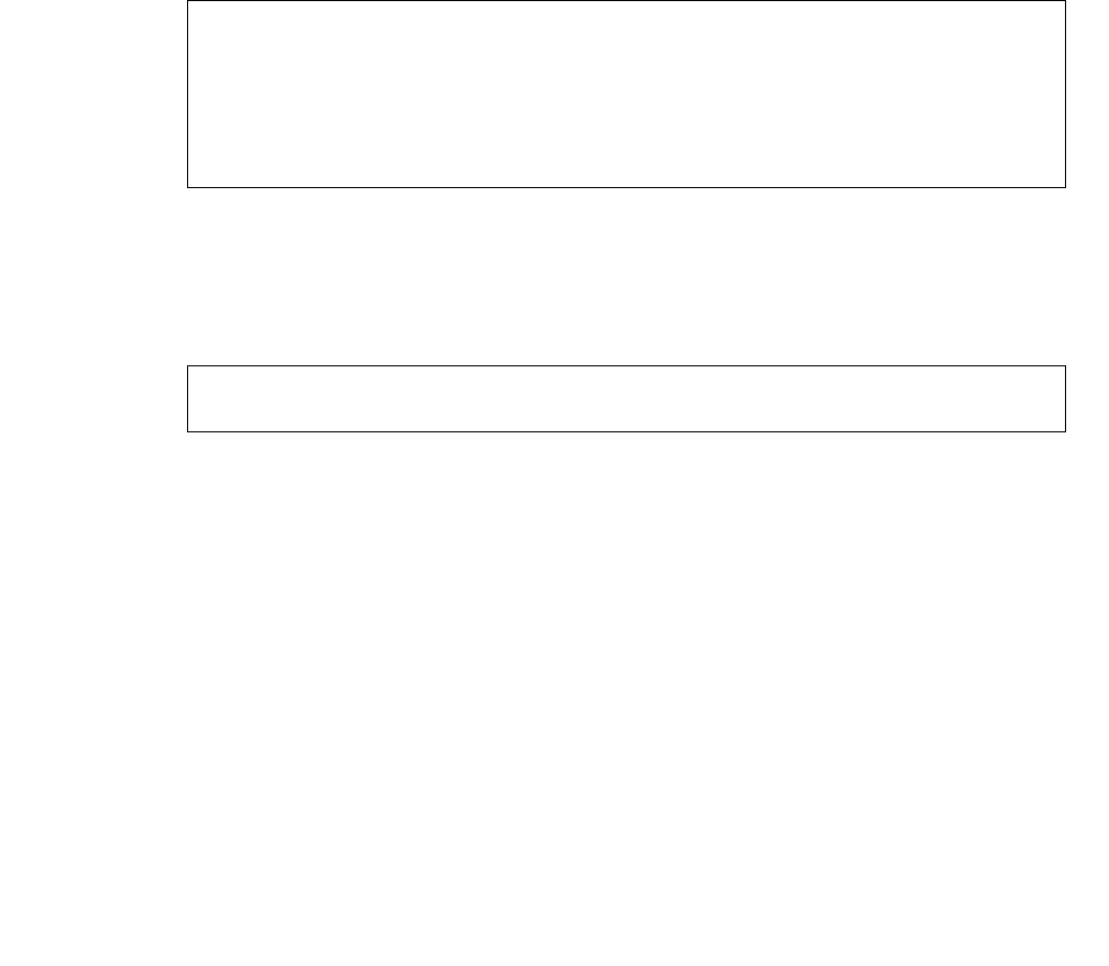
Maintenance
126 Avaya CMS Sun Ultra 5 Computer Hardware Installation, Maintenance, and Troubleshooting
Administering a replacement data disk, R3V8 and earlier
To administer a new data disk drive that is a replacement for a defective data disk drive:
1. Verify that the disk has been partitioned.
2. Enter the following commands to set the path variables:
PATH=$PATH:/usr/opt/SUNWmd/sbin:/olds
export PATH
3. Enter:
olds -check_disks
This checks the disk partitioning.
A message similar to the following is displayed:
4. Enter:
olds -mk_files
The following message is displayed:
5. Enter:
olds -metadbs
This sets up the metadevices. Ignore any error messages about failures while
activating new replicas.
disk:cot0d0 is partitioned ok
disk:cot1d0 is partitioned ok
disk:cot2d0 is partitioned ok
Warning: Current Disk has mounted partitions
disk:cot0d0 is partitioned ok
Success, checking disks
#
Success, creating md.tab.new and/or vfstab.new
#
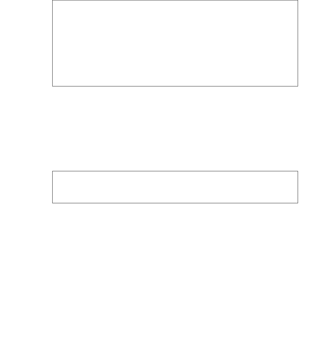
Maintaining disk drives
Issue 3.3 February 2003 127
6. Enter:
nohup olds -setup | tee
This sets up the /cms metadevice.
The following message is displayed:
7. Enter:
mount /cms
This mounts the /cms file system.
8. Enter:
df -k /cms
The file system information for /cms is displayed. For example:
The kbytes figure should be somewhat smaller than the total disk space on the entire
system. In this example, the filesystem space is 15-GB for a system that has four 4.2-
GB disk drives. This implies that the replacement disk drive has been successfully
administered.
9. For an R3V6 or earlier system, install the swap file by entering:
olds -addswapfile /cms
10. Enter:
/usr/sbin/shutdown -y -i6 -g0
The system reboots.
...
prtvtoc: c0t6d0s0: device busy
device: c0t0d0 will not be used
valid disks are c0t0d0 c0t1d0 c0t2d0 c0t3d0
...
super-block backups (for fsck -F ufs -o b=#) at:
32, 16240, 32448, 48656, 64864, 81072, 97280, 113488,
...
10532656, 10548864, 10565072, 10580000, 10596208
ufs fsck: sanity check: /dev/md/rdsk/d19 okay
Success, activating or growing /cms metadevice
#
# df -k /cms
Filesystem kbytes used avail capacity Mounted on
/dev/md/dsk/d19 15271904 670412 14601492 5% /cms
#

Maintenance
128 Avaya CMS Sun Ultra 5 Computer Hardware Installation, Maintenance, and Troubleshooting
11. Continue with one of the following:
●Restoring the /cms filesystem (R3V8) on page 128
●Restoring the /cms filesystem (R3V6 and earlier) on page 129
Restoring the /cms filesystem (R3V8) – After administering the replacement disk, you
must now restore the /cms filesystem. This procedure is for CMS R3V8.
To restore the /cms filesystem on the replacement disk drive:
1. Restore the most recent CMSADM backup by loading the backup tape into the tape
drive and entering the following command on a single line at the command prompt:
nohup cpio -icmudv -C 10240 -I /dev/rmt/<dev#> -M “Insert
tape number %d” “cms” “cms/*” | tee
The device number (<dev#>) is usually 0c, but could be 0, 1, or 1c.
Note:
Note: You may get four error messages concerning the /home directory. These
errors are displayed when the directory is already present, so you can
ignore them.
2. You must run CMS setup to reinstall the data tables before you do a maintenance
restore. Use the information you collected before you installed the replacement disk.
See the software installation, maintenance, and troubleshooting document for CMS
setup procedures.
3. Turn on CMS.
4. Restore any CMS maintenance backups you have that are dated after the latest
CMSADM backup. See the CMS Administration document for more information.
5. Perform a CMSADM file system backup to back up the updated system configuration.
See your CMS software installation, maintenance, and troubleshooting document for
details.

Maintaining disk drives
Issue 3.3 February 2003 129
Restoring the /cms filesystem (R3V6 and earlier) – After administering the replacement
disk, you must now restore the /cms filesystem. This procedure is for CMS R3V6 and
earlier.
To restore the /cms filesystem on the replacement disk drive:
1. Enter:
ulimit unlimited
2. Restore the most recent CMSADM backup by loading the backup tape into the tape
drive and entering the following command on a single line at the command prompt:
nohup cpio -icmudv -C 10240 -I /dev/rmt/<dev#> -M “Insert
tape number %d” “/cms” “/cms/*” | tee
The device number (<dev#>) is usually 0c, but could be 0, 1, or 1c.
Note:
Note: You may get four error messages concerning the /home directory. These
errors are displayed when the directory is already present, so you can
ignore them.
3. Turn on CMS.
4. Restore any CMS maintenance backups you have that are dated after the latest
CMSADM backup. See the CMS Administration document for more information.
5. Perform a CMSADM file system backup to back up the updated system configuration.
See your CMS software installation, maintenance, and troubleshooting document for
details.
Maintenance
130 Avaya CMS Sun Ultra 5 Computer Hardware Installation, Maintenance, and Troubleshooting
Replacing the CD-ROM drive
This section describes how to replace the internal CD-ROM drive.
Opening the computer
To open the computer:
1. Remove any CD-ROM disk from the drive.
2. If you have not already done so, use the following command to shut down the
computer:
/usr/sbin/shutdown -y -i0 -g0
3. Turn off the power to the computer.
4. Remove the two screws on the back of the unit that secure the cover to the chassis.
See the following figure.
5. Slide the cover back 1 or 2 inches and lift it up away from the chassis.
6. Place the cover in a convenient location so that it does not interfere with your work.
Cover Tabs
Cover
Screws
u5_remove_cover.cdr

Replacing the CD-ROM drive
Issue 3.3 February 2003 131
7. Attach an antistatic wrist strap to the metal chassis of the computer and to your wrist.
See the following figure.
8. Disconnect the AC power cord.
!Important:
!Important:
Important: If the computer has a PCI card in slot position 2, you may want to remove
that card during this procedure to make it easier to reach the components.
To remove PCI card 2, you must first remove the PCI card 2 screw. On the
Series 1 computers, this screw is on the back of the computer. On Series 2
and later computers, this screw is on the top of the frame above the PCI
card.
u5_wriststrap.cdr
PCI slot 2
screws
Maintenance
132 Avaya CMS Sun Ultra 5 Computer Hardware Installation, Maintenance, and Troubleshooting
Removing and replacing the CD-ROM drive
To remove and replace the CD-ROM drive:
1. Loosen, but do not remove the three screws that secure the diskette drive or hard drive
mounting bracket to the top of the chassis frame. See the following figure.
2. Remove the drive bracket from the chassis by sliding it back and lifting it free of the
three screws.
3. Set the drive bracket on top of the power supply.
4. Disconnect the following cables from the back of the CD-ROM drive:
●Audio cable
●CD-ROM data ribbon cable
●Power cable.
5. Remove the four screws that hold the CD-ROM drive in the CD-ROM drive bracket.
6. Push the CD-ROM drive toward the chassis front and remove.
7. Place the CD-ROM drive on an antistatic mat.
8. On the new CD-ROM drive, verify that the jumper is set to the Master (MA) position.
9. Slide the new CD-ROM drive into the CD-ROM drive bracket.
10. Attach the CD-ROM drive to the CD-ROM drive bracket using the four screws that
were removed earlier.
u5_cdrom_cables.cdr

Replacing the CD-ROM drive
Issue 3.3 February 2003 133
Tip:
Tip: Install each screw with just a few turns before you tighten all four screws.
11. Reconnect the following cables to the back of the CD-ROM drive:
●Audio cable
●CD-ROM data ribbon cable
●Power cable.
12. Reinstall the diskette drive or hard drive that you moved earlier. Tighten the three
screws that secure the drive bracket.
Closing the computer
To close the computer:
1. If you removed the PCI card from Slot 2 earlier, reinstall it now.
2. Reconnect the AC power cord to the computer.
3. Detach the ESD wrist strap.
4. Replace the cover on the computer. Slide the cover forward until it fits snugly around
the chassis.
5. Replace the two cover screws.
Tip:
Tip: Install each screw with just a few turns before you tighten both screws.

Maintenance
134 Avaya CMS Sun Ultra 5 Computer Hardware Installation, Maintenance, and Troubleshooting
Turning on the system
To turn on the system:
1. Turn on all external SCSI devices starting with the device that is farthest from the
system and working toward the system.
2. Turn on the system monitor.
3. Turn on the system.
4. Press Stop+A simultaneously after the console banner is displayed, but before the
system starts booting.
5. Enter the following commands:
setenv auto-boot? false
reset-all
This resets the system.
6. Enter:
probe-ide
This checks to see that the system recognizes the new CD-ROM drive. If the new
CD-ROM is not listed, make sure there is a secure connection between the
motherboard and the CD-ROM drive.
7. Reboot the system by entering the following commands:
!
CAUTION:
CAUTION: If you fail to enter these commands, any reboots that you do in the future will
stop at the boot prompt instead of proceeding through the normal boot-up
process.
setenv auto-boot? true
boot
The system reboots.
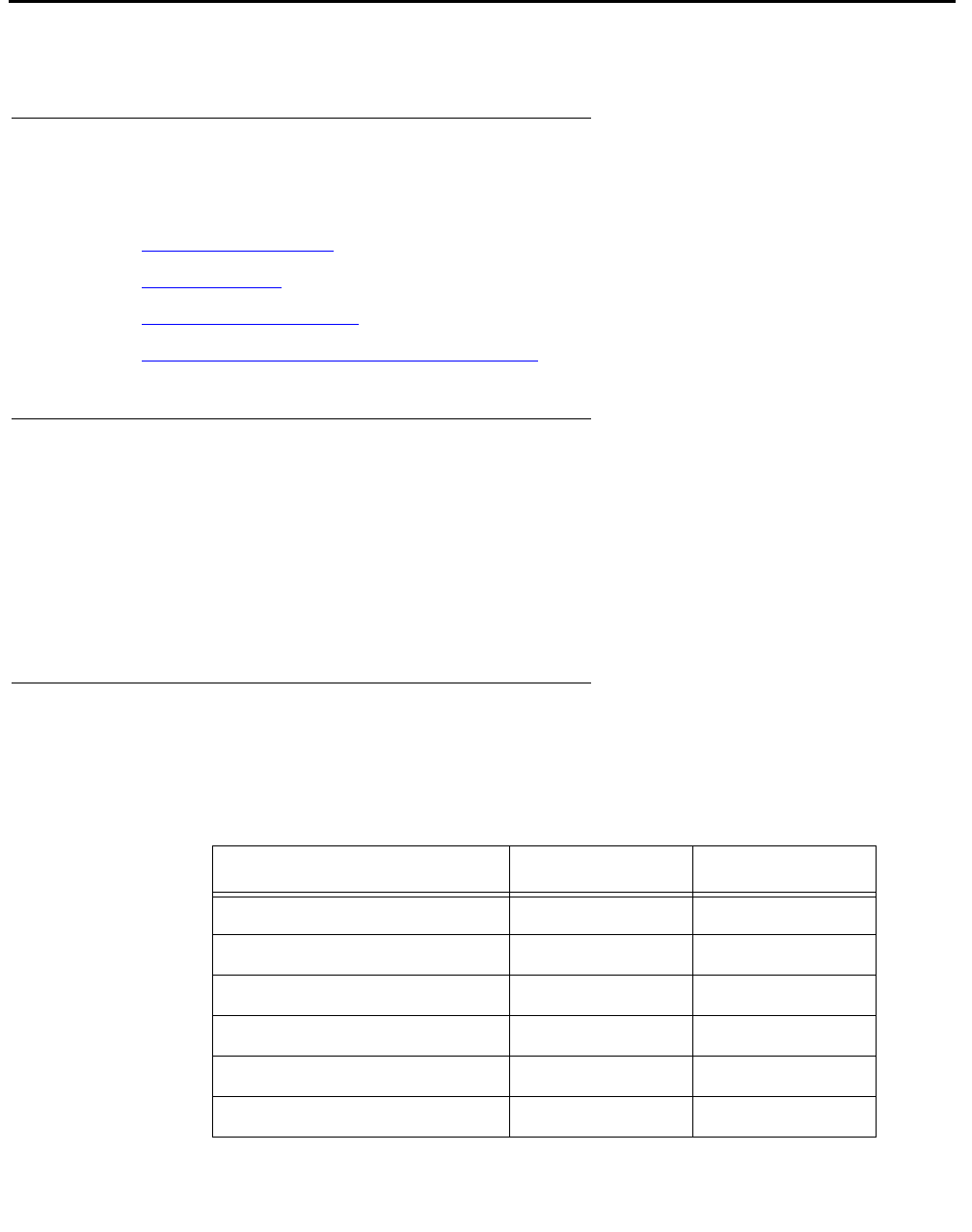
Maintaining tape drives
Issue 3.3 February 2003 135
Maintaining tape drives
Overview
Procedures in this section include the following:
●Required references on page 135
●Ordering tapes on page 135
●Cleaning the tape drive
●Adding, removing, or replacing tape drives on page 138
Required references
The following references are required when doing procedures in this section:
●Sun StorEdge™ DDS4 Tape Drive Installation and Users Guide
●Sun 4.0 Gbyte 1/4-Inch Tape Drive Specifications (SLR5)
●14 Gbyte 8mm Tape Drive Users Guide and Installation Manual
Ordering tapes
Use the following information to order replacement tapes:
Description Tape drive OEM
DDS4 20/40-GB, 4mm DDS4 Imation
DDS4 cleaning cartridge DDS4 Imation
SLR5, 4/8-GB QIC SLR5 Imation or Sony
SLR5 cleaning cartridge SLR5 Imation
14-GB, 8mm DX, XL, XS 8mm Exabyte
8mm cleaning cartridge DX, XL, XS 8mm Exabyte
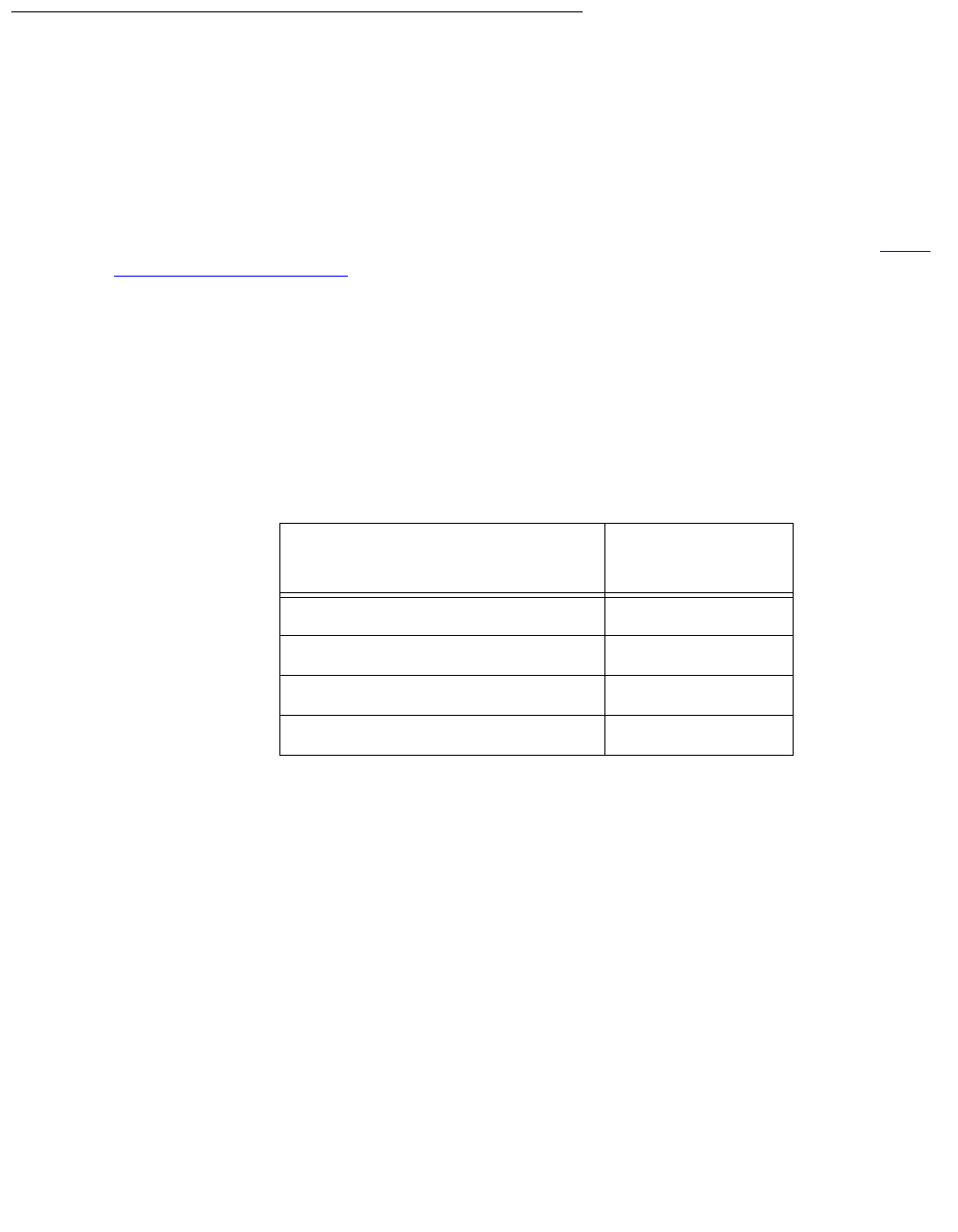
Maintenance
136 Avaya CMS Sun Ultra 5 Computer Hardware Installation, Maintenance, and Troubleshooting
Cleaning the tape drive
This section describes how you clean the following tape drives:
●DDS4, 4-millimeter, 20/40-GB
●SLR5, QIC, 4/8-GB
●XL/XS/DX 8-millimeter, 7/14-GB
The LEDs on the tape drives will indicate when the tape drives need cleaning. See Tape
drive LED status patterns on page 174.
DDS4 tape drive
The DDS4 tape drive uses a dry cleaning cartridge. Each cartridge is good for about 50
cleaning cycles. Regular cleaning is recommended to maximize tape drive performance.
The cleaning schedule depends on the number of DDS tape cartridges used each day for
backups. Use the following table to determine a cleaning schedule.
In addition, if the Clean LED flashes, either the tape drive heads need cleaning, or the
backup tape needs replacing.
To clean the tape drive:
1. Load the cleaning cartridge into the tape drive.
The cleaning cycle begins automatically, and the Tape LED flashes. When the cleaning
cycle is complete, the cleaning cartridge is ejected automatically.
2. The first time you use the cleaning cartridge, record the date on the cleaning cartridge.
Each time you clean the tape drive, mark an X in the box. After all boxes are filled,
replace the cleaning cartridge.
3. Return the cleaning cartridge to the plastic protection box.
If the Clean LED continues to flash, repeat the cleaning procedure using a different
cleaning cartridge. If the Clean LED is still flashing, repeat the backup operation with a
Number of cartridges used
each day Cleaning
interval
1 or less 8 weeks
2 4 weeks
3 3 weeks
4 or more Weekly

Maintaining tape drives
Issue 3.3 February 2003 137
different tape. If this clears the signal, the first backup tape is nearing the end of its life.
Discard the old tape.
SLR5 tape drive
The SLR5 tape drive uses a dry cleaning cartridge. Each cartridge is good for about 50
cleaning cycles. Regular cleaning (weekly or daily) is recommended to maximize tape
drive performance. Minimally, the tape drive should be cleaned after 8 hours of tape
movement.
To clean the tape drive:
1. Load the cleaning cartridge into the tape drive.
The cleaning cycle begins automatically, and the LED on the tape drive will flash
green. If the LED immediately lights steady green, use a new cleaning cartridge. If the
LED flashes red, remove the cleaning tape and reinsert it.
2. Remove the cleaning tape when the LED lights steady green.
3. The first time you use the cleaning cartridge, record the date on the cleaning cartridge.
Each time you clean the tape drive, mark an X in the box. After all boxes are filled,
replace the cleaning cartridge.
4. Return the cleaning cartridge to the plastic protection box.
XL/XS/DX tape drive
The XL/XS/DX 8mm tape drive uses a dry cleaning cartridge. Each cartridge is good for
about 20 cleaning cycles. Regular cleaning (weekly or daily) is recommended to maximize
tape drive performance. Minimally, the tape drive should be cleaned after 30 hours of tape
movement.
In addition, when 30 tape motion hours elapse, the top amber LED will light if the tape drive
heads need cleaning.
To clean the tape drive:
1. Load the cleaning cartridge into the tape drive.
The cleaning cycle begins automatically. The top LED flashes rapidly and turns off, and
the bottom LED flashes slowly. When the cleaning cycle is complete, the cleaning
cartridge is ejected automatically.
2. The first time you use the cleaning cartridge, record the date on the cleaning cartridge.
Each time you clean the tape drive, mark an X in the box. After all boxes are filled,
replace the cleaning cartridge.
3. Verify that the top amber LED turns off after the cleaning.
4. Return the cleaning cartridge to the plastic protection box.

Maintenance
138 Avaya CMS Sun Ultra 5 Computer Hardware Installation, Maintenance, and Troubleshooting
Adding, removing, or replacing tape drives
This section describes how to add, remove, or replace an external tape drive on an existing
system.
Note:
Note: External tape drives are pre-installed and required at all times. Adding a
second tape drive is usually only a temporary measure during the migration
process.
Adding or replacing a tape drive
When adding a newer model tape drive to a system, you may have to edit the
/kernel/drv/st.conf file to add information about the new tape drive. If editing the file
is required, you will receive a Design Change Letter (DCL) instructing you how to change
the file.
To add or replace a tape drive:
1. Remove any tapes from the tape drive.
2. Log in to the system as root.
3. Enter:
/usr/sbin/shutdown -y -i0 -g0
This shuts down the system.
4. Turn off the system.
5. Turn off the system monitor.
6. Turn off all external SCSI devices starting with the device that is closest to the system
and working toward the farthest device.
7. If replacing a defective tape drive, disconnect the SCSI cables and AC power cable.
8. Connect the tape drive to the other SCSI devices. See SunSwift connections on
page 139 or UltraSCSI connections on page 141.

Maintaining tape drives
Issue 3.3 February 2003 139
SunSwift connections – The following figure shows how to connect UniPack SCSI disk
drives and tape drives to a SunSwift card. A 68-to-68-pin SCSI cable connects from the
SunSwift PCI card on the back of the computer to the IN connector on the back of the SCSI
device that is closest to the computer. If you have more than one SunSwift card, connect
the drives to the card in the lowest slot number. A 68-to-68 pin SCSI cable connects from
the OUT connector of that device to the IN connector of the next device. Continue this
process until all assigned devices are connected in the SCSI chain.
.
When connecting SCSI devices, the last device in the chain MUST be terminated, either
via an auto-terminated device or with a manual terminator.
When using an auto-terminated SCSI device, you do not need to connect a SCSI
terminator to the OUT connector of the last SCSI device in the chain. To verify that the last
device is auto-terminated, check the LEDs labeled Auto Term High and Auto Term Low on
the back panel of the device. In a CMS configuration, both LEDs are lit on the last device in
the SCSI chain. If a device in the SCSI chain is not the last device, neither termination LED
is lit.
When using a manually-terminated device, you must connect a SCSI terminator to the
OUT connector of the last SCSI device in the chain. When you connect the SCSI
terminator to the OUT connector, the LED on the terminator is lit.
Stack of three
external SCSI devices
SunSwift card
in PCI slot 2
Back panel of Ultra 5
IN
IN
IN
OUT
OUT
OUT
68-to-68 pin SCSI cable
Target
address
switch
68-to-68 pin SCSI cable
scsi_sunswift.cdr
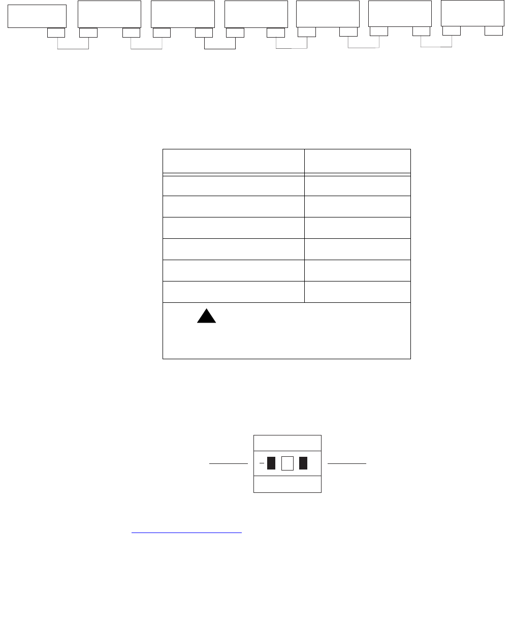
Maintenance
140 Avaya CMS Sun Ultra 5 Computer Hardware Installation, Maintenance, and Troubleshooting
The following figure shows the SCSI cabling for a SunSwift card.
SCSI devices are addressed as shown in the following table.
These addresses are set using the target address switches on the back of each SCSI
device. Before setting the target address, make sure that the power is off on the SCSI
devices.
Continue with Turning on the system on page 144.
SCSI
Connector
UniPack Disk
Drive 1
(optional)
UniPack Disk
Drive 2
(optional)
UniPack Disk
Drive 3
(optional)
UniPack Disk
Drive 4
(optional)
UniPack
Tape Drive 1
(required)
UniPack
Tape Drive 2
(optional)
WWW
WW W WA
WW
W
68-68 68-68 68-68 68-68 68-68
W = 68-68 pin SCSI cable
A = Auto-terminated
W
68-68
W
scsicble_swift.cdr
Device Address
Disk drive 1 0
Disk drive 2 1
Disk drive 3 2
Disk drive 4 3
Tape drive 1 4
Tape drive 2 5
!Important:
!Important:
Important: Do not use a target address
greater than 5.
Press this side to increase
the address number.
Press this side to decrease
the address number.
+
2
scsiidsw.cdr
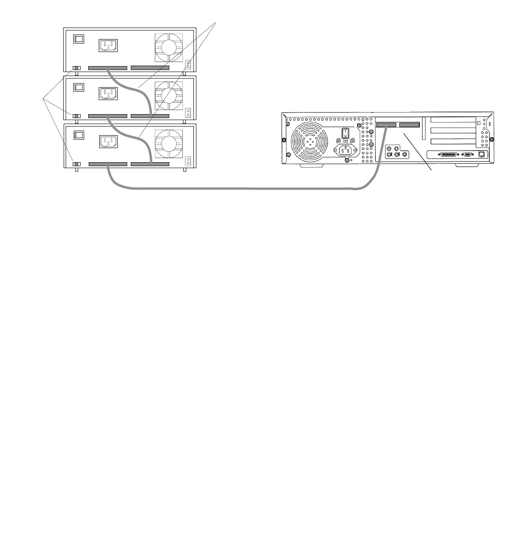
Maintaining tape drives
Issue 3.3 February 2003 141
UltraSCSI connections – The following figure shows how to connect UniPack SCSI disk
drives and tape drives to an UltraSCSI card. A 68-to-68-pin VHDCI SCSI cable connects
from the UltraSCSI PCI card on the back of the computer to the IN connector on the back
of the SCSI device that is closest to the computer. A 68-to-68 pin SCSI cable connects
from the OUT connector of that device to the IN connector of the next device. Continue this
process until all assigned devices are connected in the SCSI chain.
.
When connecting SCSI devices, the last device in the chain MUST be terminated, either
via an auto-terminated device or with a manual terminator.
When using an auto-terminated SCSI device, you do not need to connect a SCSI
terminator to the OUT connector of the last SCSI device in the chain. To verify that the last
device is auto-terminated, check the LEDs labeled Auto Term High and Auto Term Low on
the back panel of the device. In a CMS configuration, both LEDs are lit on the last device in
the SCSI chain. If a device in the SCSI chain is not the last device, neither termination LED
is lit.
When using a manually-terminated device, you must connect a SCSI terminator to the
OUT connector of the last SCSI device in the chain. When you connect the SCSI
terminator to the OUT connector, the LED on the terminator is lit.
68-to-68 pin VHDCI cable
Stack of three
external SCSI devices
Dual-channel
UltraSCSI card in PCI slot 2
IN
IN
IN
OUT
OUT
OUT
68-to-68 pin SCSI cable
Target
address
switch
Back panel of Ultra 5
scsiuni.cdr
(left) (right)
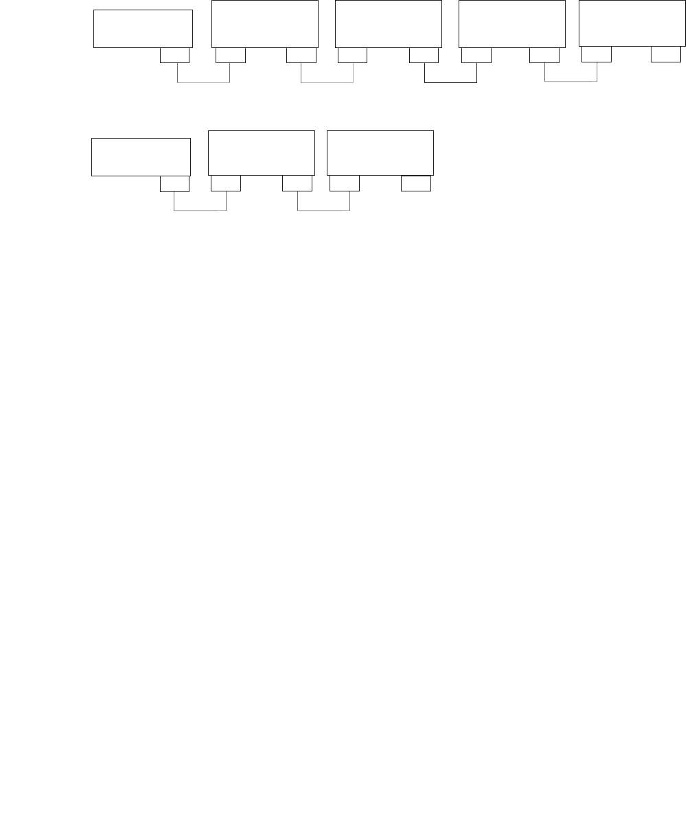
Maintenance
142 Avaya CMS Sun Ultra 5 Computer Hardware Installation, Maintenance, and Troubleshooting
The following figure shows the SCSI cabling schemes that are possible with an UltraSCSI
card that is installed in slot 2 of an Ultra 5 computer.
Note:
Note: The “Left/Right” designations shown above are based on the UltraSCSI card
being installed in slot 2. If the UltraSCSI card is installed in slots 1 or 3,
connect the disk drives to the right connector and the tape drives to the left
connector.
Left SCSI
Connector
Right SCSI
Connector
UniPack Disk
Drive 1
(optional)
UniPack Disk
Drive 2
(optional)
UniPack Disk
Drive 3
(optional)
UniPack Disk
Drive 4
(optional)
UniPack
Tape Drive 1
(required)
UniPack
Tape Drive 2
(optional)
VV
VV
W W W A
A
W
W W
68-68
68-68
68-68 68-68
68-68
V = 68-68 pin VHDCI cable
W = 68-68 pin SCSI cable
A = Auto-terminated
W
68-68
W
scsicble.cdr
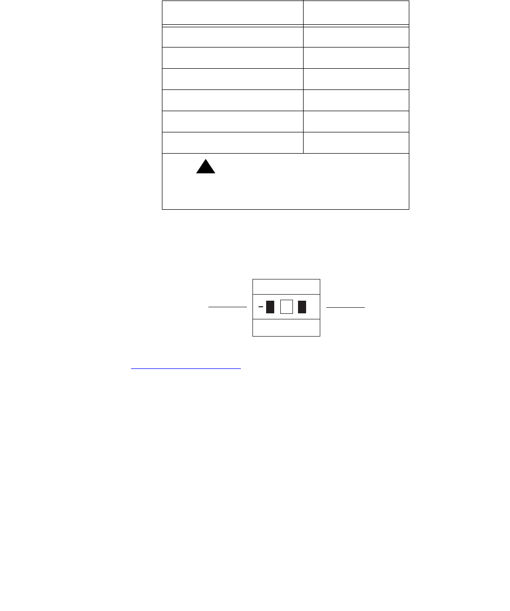
Maintaining tape drives
Issue 3.3 February 2003 143
SCSI devices are addressed as shown in the following table.
These addresses are set using the target address switches on the back of each SCSI
device. Before setting the target address, make sure that the power is off on the SCSI
devices.
Continue with Turning on the system on page 144.
Device Address
Disk drive 1 0
Disk drive 2 1
Disk drive 3 2
Disk drive 4 3
Tape drive 1 4
Tape drive 2 5
!Important:
!Important:
Important: Do not use a target address
greater than 5.
Press this side to increase
the address number.
Press this side to decrease
the address number.
+
2
scsiidsw.cdr

Maintenance
144 Avaya CMS Sun Ultra 5 Computer Hardware Installation, Maintenance, and Troubleshooting
Turning on the system – To turn the system on:
1. Connect the power cord from the tape drive to a power source.
2. Turn on all external SCSI devices starting with the device that is farthest from the
system and working toward the system.
3. Turn on the system monitor.
4. Turn on the system.
5. Press Stop+A simultaneously after the console banner is displayed, but before the
system starts booting.
6. Enter the following commands:
setenv auto-boot? false
reset-all
This resets the system.
7. Enter:
probe-scsi-all
This checks to see that the system recognizes the new tape drive. The resulting
display should list the new drive as Target 4 or Target 5. If the new drive is not listed,
check for a secure connection between the SCSI port and the new drive.
8. Reboot the system by entering the following commands:
!
CAUTION:
CAUTION: If you fail to enter these commands, any reboots that you do in the future will
stop at the boot prompt instead of proceeding through the normal boot-up
process.
setenv auto-boot? true
boot -r
The system reboots.
9. Perform a CMSADM file system backup to back up the updated system configuration.
See your CMS software installation, maintenance, and troubleshooting document for
details.

Maintaining tape drives
Issue 3.3 February 2003 145
Removing a tape drive
To remove a tape drive:
1. Log in to the system as root.
2. Enter the following commands:
cd /dev/rmt
pwd
The pwd command verifies that you are in the /dev/rmt directory.
3. Enter:
rm *
This removes SCSI tape drive device files. If you do not remove the tape drive device
files before rebooting the system, the SCSI tape drive device files may not match the
hardware configuration.
4. Enter:
/usr/sbin/shutdown -y -i0 -g0
This shuts down the system.
5. Turn off the system.
6. Turn off the system monitor.
7. Turn off all external SCSI devices starting with the device that is closest to the system
and working toward the farthest device.
8. Disconnect the tape drive from the SCSI port or SCSI chain.
9. Turn on all external SCSI devices starting with the device that is farthest from the
system and working toward the system.
10. Turn on the system monitor.
11. Turn on the system.
12. Press Stop+A simultaneously after the console banner is displayed, but before the
system starts booting.
13. Enter the following commands:
setenv auto-boot? false
reset-all
This resets the system.
14. Enter:
probe-scsi-all
This displays the current SCSI devices. The removed tape drive should not be listed.

Maintenance
146 Avaya CMS Sun Ultra 5 Computer Hardware Installation, Maintenance, and Troubleshooting
15. Reboot the system by entering the following commands:
!
CAUTION:
CAUTION: If you fail to enter these commands, any reboots that you do in the future will
stop at the boot prompt instead of proceeding through the normal boot-up
process.
setenv auto-boot? true
boot -r
The system reboots.
16. Perform a CMSADM file system backup to back up the updated system configuration.
See your CMS software installation, maintenance, and troubleshooting document for
details.
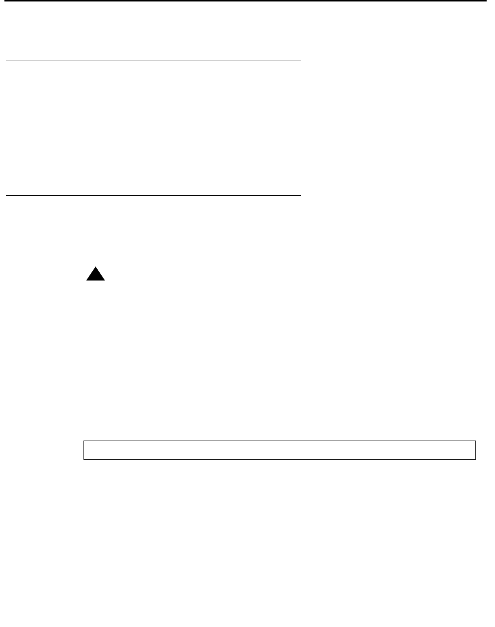
Adding memory and replacing the CPU
Issue 3.3 February 2003 147
Adding memory and replacing the CPU
Overview
The Ultra 5 comes equipped with one bank of dual inline memory modules (DIMMs) (256
MB) installed. If you need to install additional DIMMs, they must be installed in full banks
(pairs).
The computer comes equipped with one CPU. If the CPU fails, it should be replaced by a
qualified Sun technician. Contact your Avaya representative for more information.
Installing memory
This section describes the procedures used to add more memory to an Ultra 5 system that
is currently in operation.
!WARNING:
WARNING: You must wear an ESD wrist strap when installing or removing hardware
components to prevent electrical discharge that can damage the system.
Checking the current memory size
To check the current memory size:
1. Enter:
prtconf | grep Memory
This displays the current memory size.
2. Record the current memory size.
Memory size: xxx Megabytes
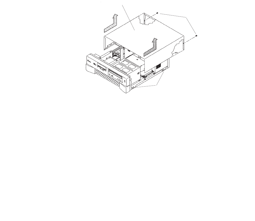
Maintenance
148 Avaya CMS Sun Ultra 5 Computer Hardware Installation, Maintenance, and Troubleshooting
Opening the computer
To open the computer:
1. If you have not already done so, use the following command to shut down the
computer:
/usr/sbin/shutdown -y -i0 -g0
2. Turn off the system.
3. Turn off the system monitor.
4. Turn off all external SCSI devices starting with the device that is closest to the system
and working toward the farthest device.
5. Remove the two screws on the back of the unit that secure the cover to the chassis.
See the following figure.
6. Slide the cover back 1 or 2 inches and lift it up away from the chassis.
7. Place the cover in a convenient location so that it does not interfere with your work.
Cover Tabs
Cover
Screws
u5_remove_cover.cdr

Adding memory and replacing the CPU
Issue 3.3 February 2003 149
8. Attach an antistatic wrist strap to the metal chassis of the computer and to your wrist.
See the following figure.
9. Disconnect the AC power cord.
!Important:
!Important:
Important: If the computer has a PCI card in slot position 2, you may want to remove
that card during this procedure to make it easier to reach the components.
To remove PCI card 2, you must first remove the PCI card 2 screw. On the
Series 1 computers, this screw is on the back of the computer. On Series 2
and later computers, this screw is on the top of the frame above the PCI
card.
u5_wriststrap.cdr
PCI slot 2
screws
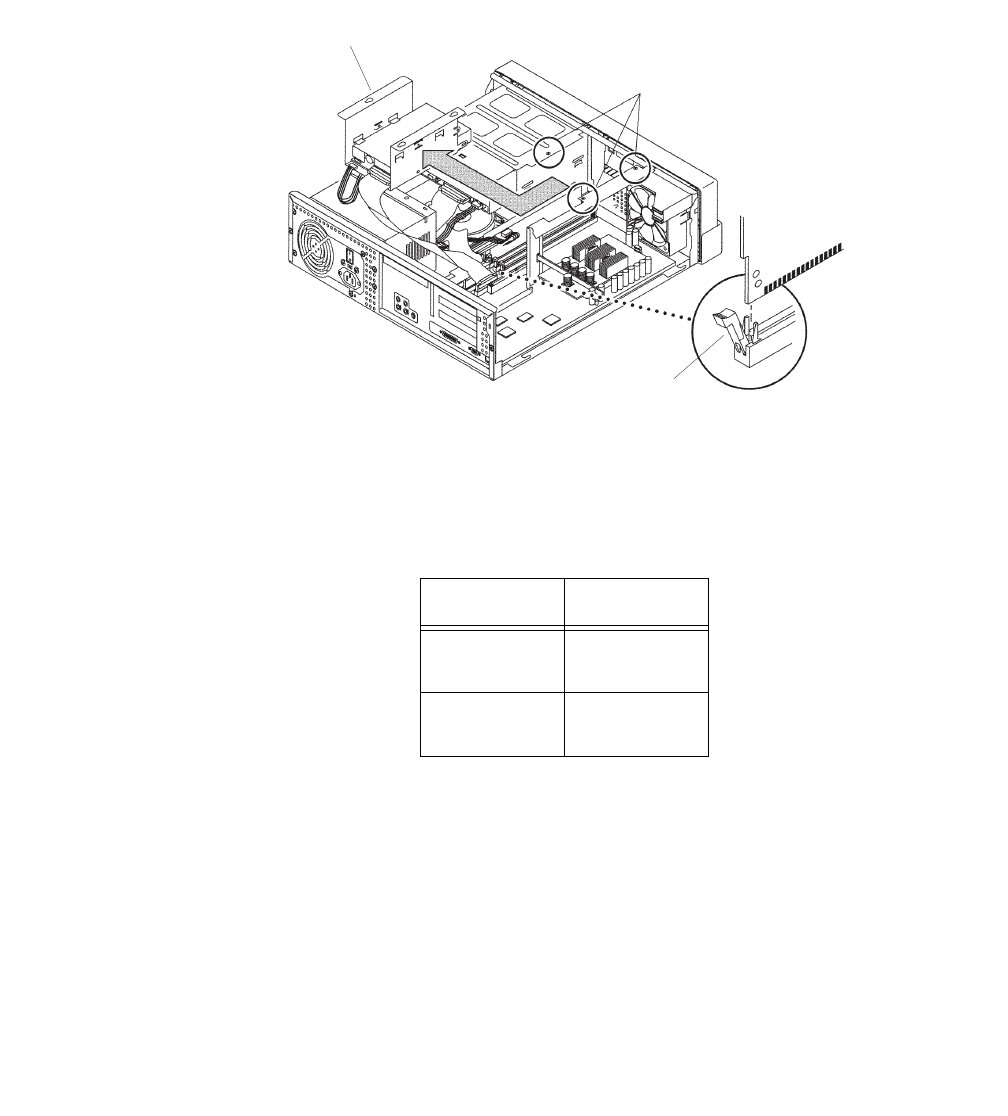
Maintenance
150 Avaya CMS Sun Ultra 5 Computer Hardware Installation, Maintenance, and Troubleshooting
Adding the DIMMs
To add the DIMMs:
1. Loosen the three screws that hold the diskette or second hard disk drive bracket and
move the disk drive out of the way. See the following figure.
The computer must have at least two identical DIMMs installed in paired sockets of any
DIMM bank. For best system performance, install four identical DIMMs. Install the
DIMMs as shown in the table below.
2. Remove the DIMM from the antistatic container.
3. Starting with the first empty slot, unlock (press down) the ejector levers at both ends of
the connectors.
4. Position the DIMM in the connector, ensuring that the notches on the bottom of the
DIMM are aligned with the connector alignment keys.
5. Press firmly on both of the top ends of the DIMM at the same time until the DIMM is
properly seated.
6. Verify that the ejection levers are closed toward the DIMM.
DIMM bank Slot pairs
0 DIMM1 and
DIMM2
1 DIMM3 and
DIMM4
Screws (3)
Ejection
Lever
Disk or
Diskette
Drive
u5_memory.cdr

Adding memory and replacing the CPU
Issue 3.3 February 2003 151
7. Repeat this procedure for each DIMM.
8. Replace the diskette/disk drive bracket and tighten the screws that hold the bracket.
Closing the computer
To close the computer:
1. If you removed the PCI card from Slot 2 earlier, reinstall it now.
2. Reconnect the AC power cord to the computer.
3. Detach the ESD wrist strap.
4. Replace the cover on the computer. Slide the cover forward until it fits snugly around
the chassis.
5. Replace the two cover screws.
Tip:
Tip: Install each screw with just a few turns before you tighten both screws.
Checking the new memory size
To check the new memory size:
1. Turn on all external SCSI devices starting with the device that is farthest from the
system and working toward the system.
2. Turn on the system monitor.
3. Turn on the system.
4. When the system comes up, log in as root.
5. Enter:
prtconf | grep Memory
This displays the new memory size.
6. Verify that the displayed memory size is correct, comparing it to the value recorded
before you added the new memory. If the new figure is not correct, power down the
system and check that all memory modules are properly seated.
Memory size: xxx Megabytes

Maintenance
152 Avaya CMS Sun Ultra 5 Computer Hardware Installation, Maintenance, and Troubleshooting
Adding swap space (R3V6 or earlier only)
After adding memory to a system that is running CMS R3V6 or earlier, the system must be
administered to allow the swap function to use the additional memory.
To add swap space:
1. Enter:
swap -a /cms/swap
2. Enter:
swap -l

Issue 3.3 February 2003 153
Troubleshooting
Overview
This chapter describes the following troubleshooting procedures:
●Using the remote console on page 154
●Tools on page 161
—Using the prtdiag command on page 162
—System messages on page 163
—OpenBoot PROM firmware tests on page 164
—OpenBoot diagnostic testson page 169
—POST diagnostic messages on page 172
—OpenBoot initialization commands on page 173
—Diagnosing LED patterns on page 174
—Sun Validation Test Suite (VTS) on page 176
●Troubleshooting disk drives and CD-ROM drives on page 177
●Troubleshooting tape drives on page 179
●Recovery procedures on page 182
References
See the Sun Ultra 5 Service Manual for additional troubleshooting procedures.
Troubleshooting
154 Avaya CMS Sun Ultra 5 Computer Hardware Installation, Maintenance, and Troubleshooting
Using the remote console
Overview
If your system does not boot, or the system cannot be diagnosed locally, remote support
personnel might want to redirect control of the console port from the local console to a
dialed-in remote console. Redirecting the console allows support personnel to do remote
maintenance as if they were at the local console. You can redirect the console using either:
●The Solaris operating system
●OpenBoot diagnostics
This section consists of the following procedures:
●Redirecting the console using Solaris on page 154. Use this procedure when the
system will boot up to the Solaris operating system.
●Redirecting the console using OpenBoot mode on page 157. Use this procedure when
the system will not boot up to the Solaris operating system.
Redirecting the console using Solaris
This procedure describes how to use the Solaris operating system to redirect the local
console to serial port B. This procedure is usually done from the remote console that has
dialed in to the system. Should you encounter any problems setting up the remote console,
see Remote console port problems on page 186.
!
CAUTION:
CAUTION: Use this procedure only when absolutely necessary. If the console redirects
and the modem line drops, you may not be able to get back into the system.
Redirecting the local console to the remote console
To redirect control of the console port from the local console to a dialed-in remote console:
1. Dial in from the remote console to the remote console modem, and log in as root.
Using the remote console
Issue 3.3 February 2003 155
2. At the remote console, enter:
/cms/install/bin/abcadm -r ttyb
The following message is displayed at the remote console:
3. At the remote console, enter: y
The following message is displayed at the remote console:
4. At the remote console, enter:
/cms/install/bin/abcadm -c -b 9600 ttyb
The following message is displayed at the remote console:
5. At the remote console, enter: y
The following message is displayed at the remote console:
The following occurs:
●The system begins to shut down.
●Shutdown, reset, and reboot messages are displayed on the local console.
●When the system starts to come back up, the local console goes blank.
●The system boot diagnostics are displayed on the remote console.
●After the system reboots, a console login: prompt is displayed on the remote
console.
6. Log in to the remote console as root.
!
CAUTION:
CAUTION: Do not enter Ctrl+D from the remote console to exit the system without first
redirecting control back to the local console. If you do, you may lock yourself
from using the console locally or remotely.
ttyb is currently set to be incoming
Are you sure you want to change it? [y,n,?]
ttyb administration removed
This change requires a reboot to take affect
Are you ready to reboot? [y,n,?]
done
desktop auto-start disabled
Proceeding to reboot.

Troubleshooting
156 Avaya CMS Sun Ultra 5 Computer Hardware Installation, Maintenance, and Troubleshooting
Redirecting the remote console back to the local console
To redirect control of the console port from the remote console back to the local console:
1. At the remote console, enter:
/cms/install/bin/abcadm -c local
The following message is displayed at the remote console:
2. At the remote console, enter: y
The following occurs:
●The system begins to shut down.
●Shutdown, reset, and reboot messages are displayed on the remote console.
●When the system starts to come back up, the system boot diagnostics are displayed
on the local console.
●After the system reboots, the console login: prompt is displayed on the remote
console.
●The login screen is displayed on the local console.
3. Log in to the local console as root.
4. Log in to the remote console as root.
Control of the console port is redirected from the remote console back to the local
console.
Console set to local
This change requires a reboot to take affect
Are you ready to reboot? [y,n,?]
Using the remote console
Issue 3.3 February 2003 157
Redirecting the console using OpenBoot mode
This procedure describes how to use the OpenBoot mode to redirect the local console to
serial port A. Use the OpenBoot mode to redirect the remote console port when the Solaris
method does not work. This typically occurs when the system will not boot.
Redirecting the local console to the remote console
To redirect control of the console port from the local console to a dialed-in remote console:
1. If the system is not already at the ok prompt, enter:
/usr/sbin/shutdown -y -i0 -g0
The system shuts down to the ok prompt.
!
CAUTION:
CAUTION: If the shutdown command fails, press Stop+A simultaneously after the
console banner is displayed, but before the operating system starts booting.
2. At the local console, enter the following commands to set the remote console
configuration parameters:
setenv input-device ttyb
setenv output-device ttyb
setenv ttyb-rts-dtr-off true
setenv ttyb-ignore-cd true
setenv ttyb-mode 9600,8,n,1,-
3. To verify the parameter changes, enter:
printenv
The following message is displayed:
4. If not already dialed in, dial in to the system from the remote console.
5. Log in to the system as root.
Parameter Name Value Default Value
output-device ttyb screen
input-device ttyb keyboard
.
.
.

Troubleshooting
158 Avaya CMS Sun Ultra 5 Computer Hardware Installation, Maintenance, and Troubleshooting
6. At the local console, enter:
boot
The following occurs:
●The system begins to shut down.
●Shutdown, reset, and reboot messages are displayed on the local console.
●When the system starts to come back up, the local console goes blank.
●The system boot diagnostics are displayed on the remote console.
●After the system reboots, a console login: prompt is displayed on the remote
console.
7. Log in to the remote console as root.
!
CAUTION:
CAUTION: Do not enter Ctrl+D from the remote console to exit the system without first
redirecting control back to the local console. If you do, you may lock yourself
from using the console locally or remotely.
Redirecting the remote console back to the local console
Using OpenBoot mode, there are two ways to redirect control of the console port from the
remote console back to the local console:
●From the remote console (recommended)
●From the local site (not recommended)

Using the remote console
Issue 3.3 February 2003 159
Method 1: from the remote console – To redirect control of the console port from the
remote console back to the local console:
1. Do one of the following:
●At the remote console, if the system is in UNIX, enter the following commands:
eeprom output-device=screen
eeprom input-device=keyboard
eeprom ttyb-rts-dtr-off=true
eeprom ttyb-ignore-cd=false
/usr/sbin/shutdown -y -i6 -g0
●At the remote console, if the system is in OpenBoot mode, enter the following
commands:
setenv output-device screen
setenv input-device keyboard
setenv ttyb-rts-dtr-off true
setenv ttyb-ignore-cd false
reset
The following occurs:
●The system begins to shut down.
●Shutdown, reset, and reboot messages are displayed on the remote console.
●When the system starts to come back up, the system boot diagnostics are displayed
on the local console.
●The login screen is displayed on the local console.
2. At the remote console, hang up the modem connection.
3. Log in to the system as root at the local console.
4. To see what is on the ttyb port, enter:
/cms/install/bin/abcadm -k
5. To start a port monitor on ttyb, enter:
/cms/install/bin/abcadm -i -b 9600 ttyb
Troubleshooting
160 Avaya CMS Sun Ultra 5 Computer Hardware Installation, Maintenance, and Troubleshooting
Method 2: from the local site – The onsite technician will use this procedure from the
local site. Use this method only when Method 1 will not work.
!
CAUTION:
CAUTION: This method of redirecting the console port should only be done as a last
resort. This procedure resets the NVRAM defaults to the Sun factory
settings.
To redirect control of the console port from the remote console back to the local console:
1. Turn the power off and back on for the CMS computer.
2. As the computer begins to boot up, press Stop+N simultaneously. Continue to press
Stop+N until a prompt displays on the local console.
3. At the ok prompt, enter:
boot
4. When the system boots up, log in to the system as root at the local console.
5. To see what is on the ttyb port, enter:
/cms/install/bin/abcadm -k
6. To start a port monitor on ttyb, enter:
/cms/install/bin/abcadm -i -b 9600 ttyb
The following message is displayed:
ttyb set to incoming port 9600 baud

Tools
Issue 3.3 February 2003 161
Tools
There are several tools available to help diagnose hardware problems:
●Using the prtdiag command on page 162
●System messages on page 163
●OpenBoot PROM firmware tests on page 164
●OpenBoot diagnostic testson page 169
●POST diagnostic messages on page 172
●OpenBoot initialization commands on page 173
●Diagnosing LED patterns on page 174
●Sun Validation Test Suite (VTS) on page 176

Troubleshooting
162 Avaya CMS Sun Ultra 5 Computer Hardware Installation, Maintenance, and Troubleshooting
Using the prtdiag command
The prtdiag command displays system diagnostic information.
To display this diagnostic information, enter:
/usr/platform/‘uname -m‘/sbin/prtdiag -v | pg
The following is an example of the results for an Ultra 5 computer.
System Configuration: Sun Microsystems sun4u Sun Ultra 5/10 UPA/PCI
(UltraSPARC-IIi 360MHz)
System clock frequency: 90 MHz
Memory size: 320 Megabytes
========================= CPUs =========================
Run Ecache CPU CPU
Brd CPU Module MHz MB Impl. Mask
--- --- ------- ----- ------ ------ ----
0 0 0 360 0.2 12 9.1
========================= IO Cards =====================
Bus# Freq
Brd Type MHz Slot Name Model
--- ---- ---- ---- --------------------- ---------
0 PCI-1 33 1 ebus
0 PCI-1 33 1 network-SUNW,hme
0 PCI-1 33 2 SUNW,m64B ATY,GT-C
0 PCI-1 33 3 ide-pci1095,646
0 PCI-2 33 1 scsi-glm Symbios,53C875
0 PCI-2 33 1 scsi-glm Symbios,53C875
0 PCI-2 33 2 token-ring-pci10b6,7
0 PCI-2 33 3 pci1214,334-pci1214,334
No failures found in System
===========================
========================= HW Revisions =========================
ASIC Revisions:
---------------
Cheerio: ebus Rev 1
System PROM revisions:
----------------------
OBP 3.19.4 1999/04/28 15:05 POST 3.0.7 1999/04/28 14:24
#

Tools
Issue 3.3 February 2003 163
System messages
System messages can alert you to system problems, such as a device that is about to fail.
By default, many of the messages are displayed on the system console and are stored in
/var/adm.
You can display system messages with the dmesg command. Here are some factors to
keep in mind:
●A list of the most recent messages is displayed.
●The /var/adm directory contains several message files. The most recent messages
are in /var/adm/messages and in /var/adm/messages.0. The oldest are in
/var/adm/messages.3.
●Periodically, a new file is created, and the /var/adm/messages.3 file is deleted,
/var/adm/messages.2 is renamed /var/adm/messages.3,
/var/adm/messages.1 is renamed /var/adm/messages.2, and
/var/adm/messages.0 is renamed /var/adm/messages.1.
The message files may contain not only system messages, but also core dumps and other
data, which can cause /var/adm to grow quite large. To keep the directory to a
reasonable size and ensure that future core dumps can be saved, you should remove
unneeded files periodically. You can automate the task by using crontab. See your Sun
system documentation for information on crontab.

Troubleshooting
164 Avaya CMS Sun Ultra 5 Computer Hardware Installation, Maintenance, and Troubleshooting
OpenBoot PROM firmware tests
The OpenBoot PROM (OBP) On-Board firmware performs a routine set of firmware and
hardware tests.
Note:
Note: Different versions of Solaris have different versions of the OpenBoot
commands. Not all commands are available with every version.
Using the OpenBoot PROM tests
To use the OpenBoot PROM tests:
1. From the root login, turn off CMS.
2. Enter:
/usr/sbin/shutdown -y -i0 -g0
The system shuts down.
3. At the ok prompt, enter the following commands:
setenv auto-boot? false
reset-all
The system resets and displays the ok prompt.
4. Use the commands that are shown in Test descriptions on page 165.
5. When you finish testing, enter the following commands:
!
CAUTION:
CAUTION: If you fail to enter these commands, any reboots that you do in the future will
stop at the boot prompt instead of proceeding through the normal boot-up
process.
setenv auto-boot? true
boot -r
The system reboots.
Tools
Issue 3.3 February 2003 165
Test descriptions
The following table lists some of the OpenBoot PROM On-Board firmware test commands.
Note that some commands give responses for the tests. Other tests just display the ok
prompt when the test passes.
Additional references – See the Sun OpenBoot 3.x Command Reference Manual for
more information.
Command Description
probe-ide-all This command identifies the devices attached to the IDE bus.
probe-scsi-all This command identifies the devices attached to the SCSI bus.
probe-fcal-all This command identifies the devices attached to the FC-AL bus.
test-all This command runs a series of tests on the network and on
hardware components. It may take several minutes to complete.
test [alias] This command executes the specified device self-test method.
Possible values for device-specifier are listed in the Alias column:
Alias Description
memory memory
cdrom cdrom
tape0-1 tape drives
disk0-5 SCSI drives
floppy floppy
screen video
keyboard keyboard
watch-clock This command tests the clock function.
watch-net
watch-net-all This command runs a loopback test, a transceiver test, and a
packet transmission test.

Troubleshooting
166 Avaya CMS Sun Ultra 5 Computer Hardware Installation, Maintenance, and Troubleshooting
Probing IDE devices
Symptom – The internal IDE disk drives are reporting errors.
Solution – Check the status of the IDE disk drives.
1. Enter:
/usr/sbin/shutdown -y -i0 -g0
This shuts down the system.
2. At the ok prompt, enter the following commands:
setenv auto-boot? false
reset-all
The system resets and the ok prompt displays.
3. Enter:
probe-ide
The program responds similar to the following:
Note:
Note: The actual response (devices listed) depends on the devices installed on the
IDE controller. This example shows the primary internal disk drive, the CD-
ROM drive, and the diskette drive.
4. If there are disk drives other than what was shown in the display, shut down the system
and check the disk drive cabling.
5. When finished with testing, enter the following commands:
Device 0 ( Primary Master )
ATA Model: ST34342A
Device 1 ( Primary Slave )
Not present
Device 2 ( Secondary Master )
Removeable ATAPI Model: CRD-8240B
Device 3 ( Secondary Slave )
Removeable ATAPI Model:
Tools
Issue 3.3 February 2003 167
!
CAUTION:
CAUTION: If you fail to enter these commands, any reboots that you do in the future will
stop at the boot prompt instead of proceeding through the normal boot-up
process.
setenv auto-boot? true
boot -r
The system reboots.
Probing SCSI devices
Symptom – The SCSI tape, CD-ROM, or external disk drives are reporting errors.
Solution – To check the status of the SCSI devices:
1. Enter:
/usr/sbin/shutdown -y -i0 -g0
This shuts down the system.
2. At the ok prompt, enter the following commands:
setenv auto-boot? false
reset-all
The system resets.
3. Enter:
probe-scsi-all
The program displays a message that is similar to the following:
Note:
Note: The actual response (devices listed) depends on the devices installed on the
SCSI bus. This example shows an external 4.2-GB disk drive and an
external DDS4 tape drive.
4. If there are drives other than what was shown in the display, shut down the system and
check the drive cabling.
5. When finished with testing, enter the following commands:
/pci@1f,0/pci@1/pci@1/SUNW,isptwo@4
Target 0
Unit 0 Disk QUANTUM VK4550J SUN4.2G8610
Target 4
Unit 0 Removeable Tape HP C5683A C911

Troubleshooting
168 Avaya CMS Sun Ultra 5 Computer Hardware Installation, Maintenance, and Troubleshooting
!
CAUTION:
CAUTION: If you fail to enter these commands, any reboots that you do in the future will
stop at the boot prompt instead of proceeding through the normal boot-up
process.
setenv auto-boot? true
boot -r
The system reboots.
Symptom – The SCSI tape, CD-ROM, or external disk drives are reporting errors.
Solution – The system might have duplicate SCSI target addresses on one bus.
Note:
Note: Two targets may have the same target number if they are on different SCSI
busses.
To check for duplicate SCSI target addresses:
1. Unplug all but one of the disks.
2. Enter:
probe-scsi-all
Record the target number and its corresponding unit number.
3. Plug in another disk, and perform Step 2 again.
4. If you get an error, change the target number of this disk to one of the unused target
numbers.
5. Repeat Steps 2 through 4 until all the disks are plugged back in.
6. When you finish testing, enter the following commands:
!
CAUTION:
CAUTION: If you fail to enter these commands, any reboots that you do in the future will
stop at the boot prompt instead of proceeding through the normal boot-up
process.
setenv auto-boot? true
boot -r
The system reboots.
Tools
Issue 3.3 February 2003 169
OpenBoot diagnostic tests
OpenBoot Diagnostics (OBDiag) is a menu-driven tool that diagnoses system hardware.
OBDiag performs root-cause failure analysis on the referenced devices by testing internal
registers, confirming subsystem integrity, and verifying device functionality.
To use the OpenBoot diagnostic tests:
1. From the root login, turn off CMS.
2. Enter:
/usr/sbin/shutdown -y -i0 -g0
The system shuts down.
3. Enter:
obdiag
This loads the test program.
4. Enter:
obtest <command number>
See the following table for a summary of OpenBoot Diagnostic test commands.
Command
number Command
name Description
0 PCI/PCIO This command:
●Verifies the PCIO ASIC vender ID and the PCIO ASIC
device ID
●Verifies that the PCI configuration space is accessible
as half-word bytes
●Verifies the address class code
●Performs a walking ones bit test on the status register,
latency timer, and interrupt line
●Verifies that the interrupt pin is logic-level high (1) after
reset
1 EBUS
DMA/TCR
Registers
This command:
●Performs a walking ones bit test
●Verifies that the status register is properly set
●Validates the DMA capabilities and FIFOs

Troubleshooting
170 Avaya CMS Sun Ultra 5 Computer Hardware Installation, Maintenance, and Troubleshooting
2 Ethernet This command:
●Resets the ethernet channel
●Performs ethernet channel engine internal loopback
●Enables the LAN data to be routed back to the receive
MII data outputs
●Enables MII transmit data to be routed to the MII
receive data path
●Forces the twisted-pair transceiver into loopback mode
3 Keyboard This command performs an external and internal loopback.
4 Mouse This command performs a keyboard-to-mouse loopback.
5 Floppy This command verifies the diskette drive controller
initialization. You must have a formatted floppy in the
diskette drive.
6 Parallel Port This command:
●Sets up the SuperIO configuration register to enable
extended/compatible parallel port select
●Enables ECP mode and ECP DMA configuration, and
FIFO test mode.
7 Serial Port A This command invokes the uart_loopback test for serial
port A.
Note:
Note: The serial port A diagnostic will stall if the
TIP line is installed on serial port A.
8 Serial Port B This command invokes the uart_loopback test for serial
port B.
Note:
Note: The serial port B diagnostic will stall if the
TIP line is installed on serial port B.
9 NVRAM This command verifies the NVRAM operation by
performing a write and read to the NVRAM.
Command
number Command
name Description

Tools
Issue 3.3 February 2003 171
Additional references – See the Sun OpenBoot 3.x Command Reference Manual for
more information.
10 Audio This command:
●Verifies the cs4231 internal registers
●Performs a line-in to line-out external loopback
●Performs a microphone-to-headphone external
loopback
11 EIDE This command validates both the EIDE chip and EIDE bus
subsystem. This takes several minutes.
12 Video This command tests the video monitor port.
13 All Above This command validates the system unit.
Note:
Note: The “All Above” diagnostic will stall if the
TIP line is installed on serial port A or serial
port B.
14 Quit This command exits from the OpenBoot diagnostics.
15 Display this
Menu This command displays the command options.
16 Toggle
script-debug This command moves you in and out of the debug area.
17 Enable
External
Loopback
Tests
This command enables the external loopback tests.
18 Disable
External
Loopback
Tests
This command disables the external loopback tests.
Command
number Command
name Description
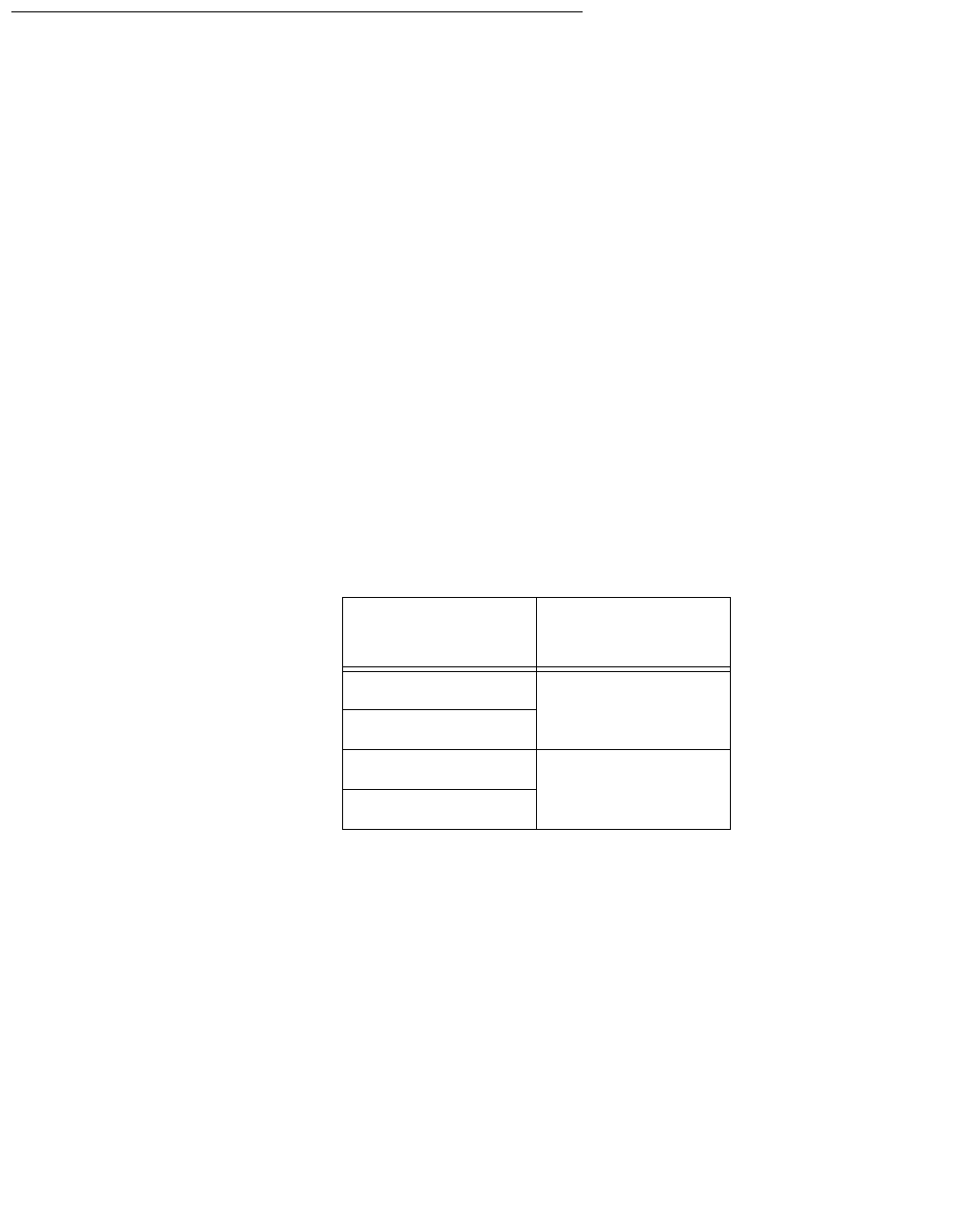
Troubleshooting
172 Avaya CMS Sun Ultra 5 Computer Hardware Installation, Maintenance, and Troubleshooting
POST diagnostic messages
To use the Power On Self Test (POST) messages (during a reboot) to diagnose remote
hardware problems:
1. At the ok prompt, enter:
boot
2. Scan the displayed messages on the screen. Watch for error messages.
You can identify problems more accurately if you are familiar with the system power-on
initialization messages. These messages show you the types of functions the system
performs at various stages of system start-up. These messages can also show the transfer
of control from OpenBoot firmware to POST.
Memory failure
The operating system, diagnostic program, or POST may not display a DIMM location (U
number) as part of a memory error message. In this situation, the only available
information is a physical memory address and failing byte. The following table lists physical
memory addresses to locate a defective DIMM.
DIMM slot DIMM pair
(non-interleave)
DIMM(0) 00000000 - 0fffffff
DIMM1
DIMM2 10000000 - 1fffffff
DIMM3
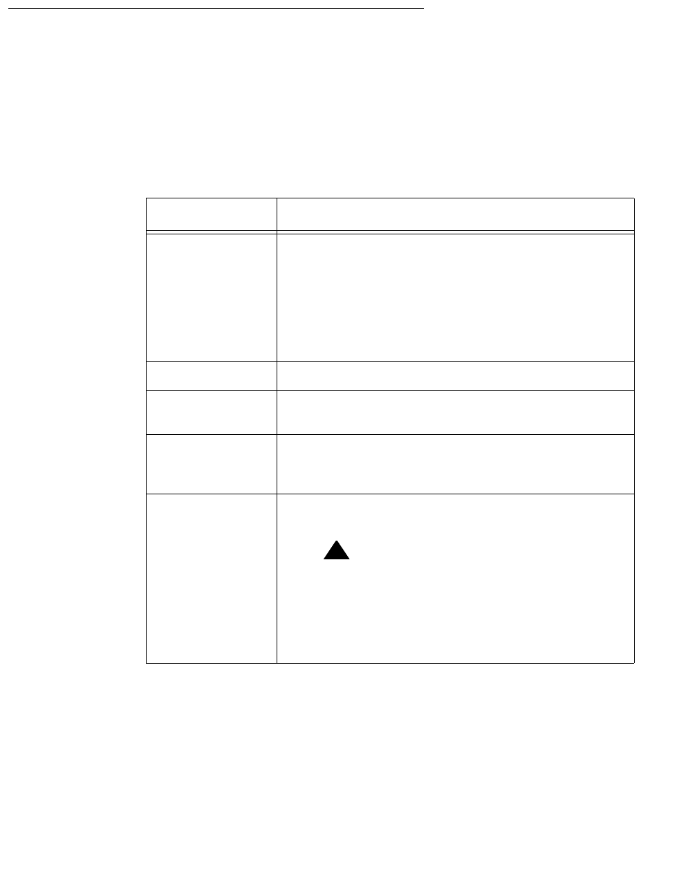
Tools
Issue 3.3 February 2003 173
OpenBoot initialization commands
The following table describes the OpenBoot initialization command sequences that are
provided by the system. These commands are useful in some situations in which the
system fails to boot. To use the commands, hold down the keys after turning on the power
to your system. Keep the keys pressed until the keyboard lights flash and the screen
displays the ok prompt.
Command Description
Stop Bypass POST. This command does not depend on
the security mode.
Note:
Note: Some systems bypass POST as a
default. In such cases, use Stop+A
to start POST.
Stop+AAbort.
Stop+DEnter diagnostic mode (set diag-switch? to
true).
Stop+FEnter Forth on TTYB instead of probing. Use exit
to continue with the initialization sequence. This is
useful if hardware is broken.
Stop+NReset NVRAM contents to default values. If this is
done, you must readminister the NVRAM options.
!
CAUTION:
CAUTION: Do not use this command under
normal operation. Running this
command causes a system to lose
the factory NVRAM settings and
the system will not boot properly.
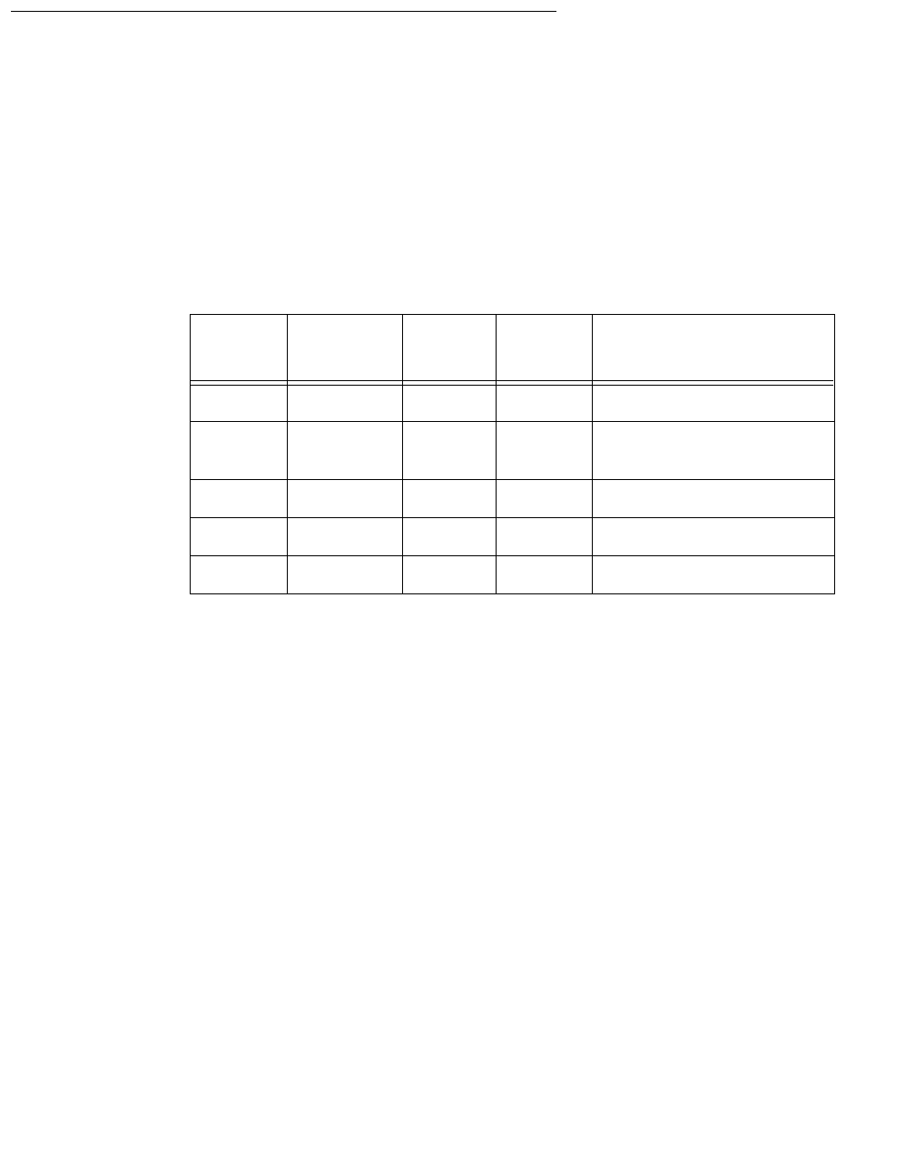
Troubleshooting
174 Avaya CMS Sun Ultra 5 Computer Hardware Installation, Maintenance, and Troubleshooting
Diagnosing LED patterns
Many hardware components of the computer have LEDs that can be used to diagnose
problems. This section describes those LED patterns.
Keyboard LED patterns
During POST, LEDs on the keyboard light in patterns that show the progress of the tests
and if any failures have been detected. The following table describes these patterns.
Tape drive LED status patterns
This section describes the LED status patterns for the following tape drives:
●DDS4, 4-millimeter, 20/40-GB
●SLR5, QIC, 4/8-GB
●XL/XS/DX, 8-millimeter, 7/14-GB
DDS4 tape drive – The tape drive LEDs show the following status:
●Tape LED (green) — The LED flashes to show activity (loading, unloading, reading, and
writing). The LED is steady when a cartridge is loaded and the tape drive is ready to
begin operation.
●Clean LED (amber) — The LED flashes to indicate that a cartridge is near the end of its
life, or that the heads need cleaning.
Caps
lock Compose Scroll
lock Num
lock Meaning
Blink Off Off Off POST in progress
Off Off Off Off POST successfully
completed
On Off Off On System board failed
On Off On Off No memory found
On On On Off Faulty CPU
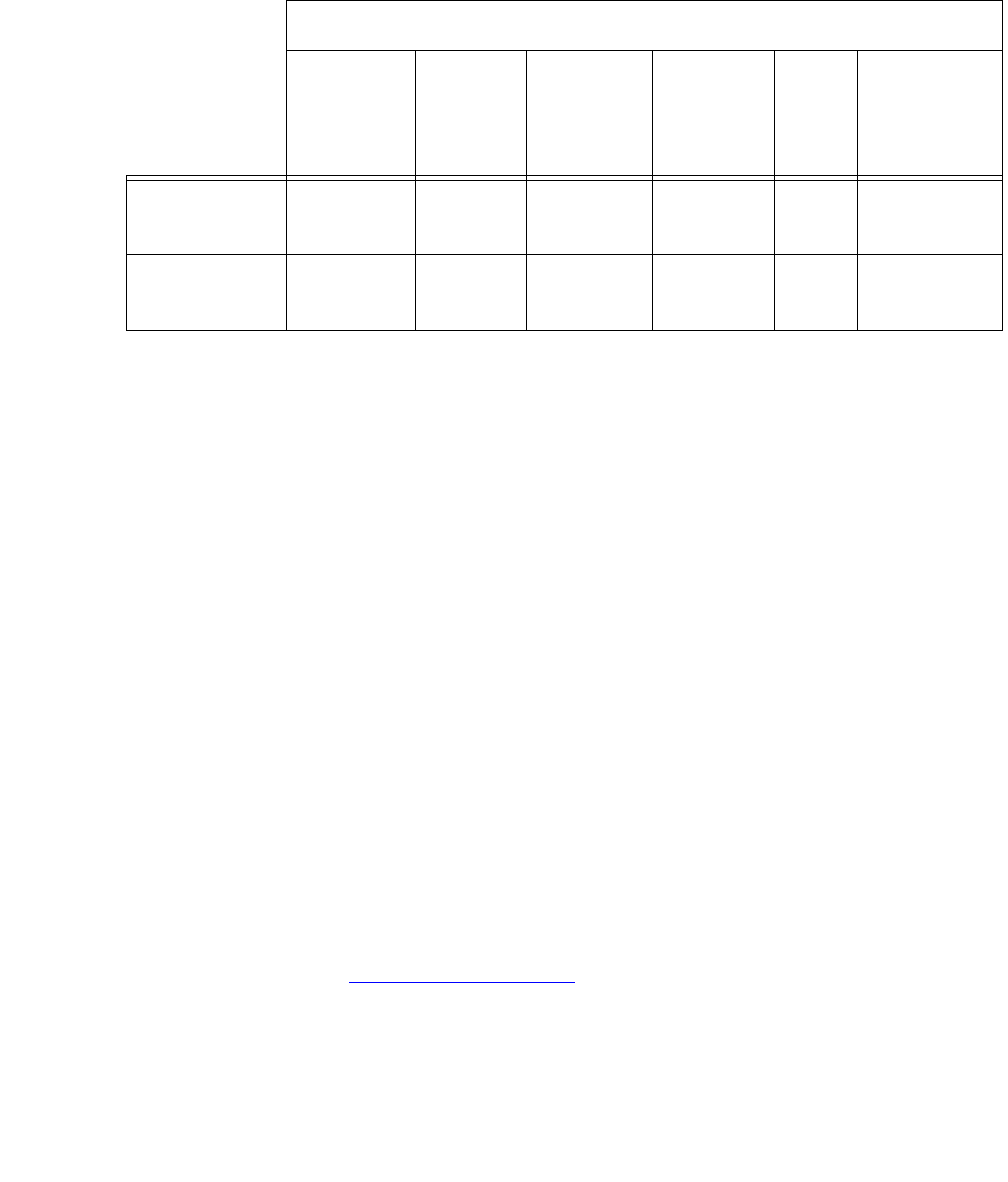
Tools
Issue 3.3 February 2003 175
The following table describes the LED combinations that occur during normal tape drive
operation.
The tape drive monitors the number of correctable errors that occur during reading and
writing. If the number of errors becomes excessive, the tape may be nearing the end of its
useful life, or the tape heads may need cleaning.
●If the media caution signal displays (flashing amber), clean the tape drive.
●If the signal still displays after cleaning the heads, repeat the operation with a different
tape. If this clears the signal, the first tape is nearing the end of its life. Copy the data
onto a new tape and discard the old one.
The media caution signal is cleared when a new tape is loaded or when the drive is power-
cycled.
SLR5 tape drive – The SLR5 tape drive has a single LED that displays both green and
red. The tape drive LED shows the following status:
●Steady green when a tape is in the tape drive. If this occurs when you first insert a
cleaning cartridge, use a new cleaning cartridge.
●Flashing green when tape drive activity is occurring.
●Flashing red when a fault occurs. When this happens, eject the tape and reinsert the
tape. If this continues to occur, the tape is faulty and should be replaced.
XL/XS/DX tape drive – The tape drive LEDs show the following status:
●Top LED (amber) — When this LED is on or flashing, the tape drive has an error or
needs cleaning (see Cleaning the tape drive on page 136).
●Middle LED (green) — When this LED is on or flashing, SCSI bus activity is occurring.
●Bottom LED (green) — When this LED is on, a tape is loaded. When this LED is
flashing, it indicates that tape motion is occurring or the tape drive needs cleaning.
Tape drive state
Activity
(load or
unload)
Activity
(read or
write)
Cartridge
loaded Media
Caution
Signal
Fault Power-on
(starts with
two steady
lights)
Tape LED
(green)
Flashing Flashing
Fast On Any Any Flashing
Clean LED
(amber)
Off Off Off Flashing On Off

Troubleshooting
176 Avaya CMS Sun Ultra 5 Computer Hardware Installation, Maintenance, and Troubleshooting
Sun Validation Test Suite (VTS)
The SunVTS™ supports diagnostics in the following areas:
●Connection test. Minimal access of device to verify its accessibility and availability.
●Functional test (default). Detailed tests to thoroughly test the device or system when
offline the system is offline (CMS must be turned off). A stress mode in the system or
test option can be set only within the offline mode. The stress mode is an extension of
offline.
●Functional test (from system monitor). Safe tests that can be executed on the device or
system when it is online (CMS can be on, but testing is safer when it is turned off).
There are two ways to run SunVTS. We recommend that you use either local access
through the Common Desktop Environment (CDE) interface, or remote access using an
ASCII interface.
Prerequisites
CMS must be turned off.
Using SunVTS
To use SunVTS:
1. Enter:
BYPASS_FS_PROBE=1; export BYPASS_FS_PROBE
This bypasses the file system probe.
2. Do one of the following:
●Enter:
/opt/SUNWvts/bin/sunvts
This accesses the CDE interface.
●Enter:
/opt/SUNWvts/bin/sunvts -t
This accesses the TTY mode (ASCII interface).
Additional references – For more information about using VTS, see the files
/opt/SUNWvts/README and /opt/SUNWvts/bin/vtstty.help.
Troubleshooting disk drives and CD-ROM drives
Issue 3.3 February 2003 177
Troubleshooting disk drives and CD-ROM drives
This section provides hard drive and CD-ROM drive failure symptoms and suggested
actions.
Symptom – A hard drive read, write, or parity error is reported by the operating system. A
CD-ROM drive read error or parity error is reported by the operating system.
Solution – Replace the drive indicated by the failure message. The operating system
identifies the internal drives as indicated in the following table.
Operating system address Drive physical location and target
c0t<X>d0s0, or
c1t<X>d0s0 Hard drive, target <X> (<X>
represents the target number 0 to 7)
c0t6d0s0 CD-ROM drive, target 6
Troubleshooting
178 Avaya CMS Sun Ultra 5 Computer Hardware Installation, Maintenance, and Troubleshooting
Symptom – The hard drive or CD-ROM drive fails to respond to commands.
Solution – When the hard drive or CD-ROM drive fails to respond to commands:
1. Enter:
/usr/sbin/shutdown -y -i0 -g0
This shuts down the system.
2. At the ok prompt, enter the following commands:
setenv auto-boot? false
reset-all
The system resets.
3. Enter:
probe-ide
The program responds similar to the following:
4. Verify that all the disk drives are recognized. This example indicates that the system
primary disk is on Device 0, and the CD-ROM is on Device 2.
If the probe-ide test fails to show all installed disk drives, you may have to replace
the disk drive.
5. When finished with testing, enter the following commands:
!
CAUTION:
CAUTION: If you fail to enter these commands, any reboots that you do in the future will
stop at the boot prompt instead of proceeding through the normal boot-up
process.
setenv auto-boot? true
boot -r
The system reboots.
Device 0 ( Primary Master )
ATA Model: ST34342A
Device 1 ( Primary Slave )
Not present
Device 2 ( Secondary Master )
Removeable ATAPI Model: CRD-8240B
Device 3 ( Secondary Slave )
Removeable ATAPI Model:

Troubleshooting tape drives
Issue 3.3 February 2003 179
Troubleshooting tape drives
Overview
Use the following procedures to troubleshoot tape drives:
●Checking tape status
●Rebuilding tape device driverson page 181
Checking tape status
For many procedures, you must identify what tape drive, by device path, you will use for
the procedure. Tape drives are assigned to particular device paths, usually one of the
following:
●/dev/rmt/0
●/dev/rmt/0c
●/dev/rmt/1
●/dev/rmt/1c
Note:
Note: The “c” at the end of the device name indicates that the tape device can
operate in compressed mode. We recommend that you use compressed
mode at all times.
Troubleshooting
180 Avaya CMS Sun Ultra 5 Computer Hardware Installation, Maintenance, and Troubleshooting
To determine what device paths are available on your system:
1. Insert a tape into the tape drive.
2. Enter the following commands:
mt -f /dev/rmt/0 status
mt -f /dev/rmt/1 status
If the device path is correct, a message similar to the following is displayed:
If the device path is incorrect, a message similar to the following is displayed:
If there is no tape in the tape drive, a message similar to the following is displayed:
Vendor ‘HP ‘ Product ‘C5683A ‘ tape drive:
sense key(0x6)= Unit Attention residual= 0 retries= 0
file no= 0 block no= 0
/dev/rmt/1c: No such file or directory
/dev/rmt/1c: No tape loaded or drive offline

Troubleshooting tape drives
Issue 3.3 February 2003 181
Rebuilding tape device drivers
As tape drives are added to and removed from a system, the device instance numbers can
get out of sequence with the number of tape drives. For example, if a system has two tape
drives, and one is removed, the system may accidentally try to use a tape drive that no
longer exists.
To reassign device instance numbers for tape devices:
1. Log in to the system as root.
2. Make sure that the target addresses for any SCSI tape drives are set correctly.
Typically, the internal tape drive is SCSI address 5, and an external tape drive is SCSI
address 4. If you change the SCSI address, you must turn the tape drive power off and
back on.
3. Insert the Solaris CD-ROM into the CD-ROM drive.
4. After about 15 seconds, enter the following commands:
boot cdrom -sw
fsck -y /dev/dsk/c1t0d0s0
mount /dev/dsk/c1t0d0s0 /a
devfsadm -vCc tape -r /a -p /a/etc/path_to_inst
This reassigns the device instance numbers for the tape devices.
5. Enter:
eject cdrom
6. Remove the Solaris CD-ROM.
Troubleshooting
182 Avaya CMS Sun Ultra 5 Computer Hardware Installation, Maintenance, and Troubleshooting
Recovery procedures
This section contains procedures to follow when certain conditions or errors occur.
Preserving data after a system failure
Enter the sync command at the ok prompt to force any information on its way to the hard
disk to be written out immediately. This is useful if the operating system fails or is
interrupted before preserving all data.
The sync command returns control to the operating system and performs the data-saving
operations. After the disk data is synchronized, the operating system begins to save a core
image of itself. If you do not need this core dump, you can interrupt the operation by
pressing Stop+A.
Loss of power
If the system loses power, it is recommended (but not required) that you empty the CD-
ROM or DVD-ROM and tape drives. The system boots from the disk by default.
Power-on sequence – To turn the power back on:
1. Turn on all external SCSI devices starting with the device that is farthest from the
system and working toward the system.
2. Turn on the system monitor.
3. Turn on the system.
If the system is operating properly, a banner screen is displayed up to 3 minutes after it
is powered on.
|------| <Product Name>, Keyboard Present
| | OpenBoot 3.xx, XXX MB memory installed, Serial #XXXXXXXXX
| | Copyright 2000 Sun Microsystems, Inc. All rights reserved.
|------| Ethernet address X:X:XX:XX:XX:XX, Host ID: XXXXXXXX
Recovery procedures
Issue 3.3 February 2003 183
Power-off sequence – To turn off the power:
1. Log in to the system as root.
2. Enter:
/usr/sbin/shutdown -y -i0 -g0
This shuts down the system.
3. Turn off the system.
4. Turn off the system monitor.
5. Turn off all external SCSI devices starting with the device that is closest to the system
and working toward the farthest device.
Keyboard becomes unplugged
If the console keyboard cable becomes unplugged during normal operation, the system
continues to operate until you plug in the keyboard cable.
!
CAUTION:
CAUTION: When you plug in the keyboard cable, the system stops running and no ACD
data is collected from the switch. Do this only when there is no traffic on the
system or when there is low traffic on the system.
To recover from this problem:
1. Plug in the keyboard cable.
The system beeps and the current display “freezes” on the monitor. A small window
that shows the following is displayed:
2. Enter:
go
The system resumes normal operation.
3. Refresh the terminal screen.
Note:
Note: If the system is rebooted, instead of entering go, you may be prompted to
use the fsck command to repair the Solaris file systems.
Type ‘go’ to resume
ok
Troubleshooting
184 Avaya CMS Sun Ultra 5 Computer Hardware Installation, Maintenance, and Troubleshooting
Probe command warnings
Symptom – When using any of the probe commands, the following message is displayed:
!
CAUTION:
CAUTION: Do not continue. Answer n. Do not answer y.
Solution – To recover from this condition:
1. Enter: n
This stops the probe command.
2. Enter the following commands:
setenv auto-boot? false
reset-all
3. Now it is acceptable to execute any of the probe commands and perform any other
boot PROM-level diagnostics.
4. After you finish probing the system devices, enter the following commands:
!
CAUTION:
CAUTION: If you fail to enter these commands, any reboots that you do in the future will
stop at the boot prompt instead of proceeding through the normal boot-up
process.
setenv auto-boot? true
boot -r
The system reboots.
This command may hang the system if a Stop-A or halt command has been
executed. Please type reset-all to reset the system before executing this
command. Do you wish to continue [Y/N].

Recovery procedures
Issue 3.3 February 2003 185
Reseating HSI/P cards
The HSI/P cards may appear to be faulty when they just need to be reseated in the PCI
slot. Before you replace the card, try reseating the card.
To reseat an HSI/P card:
1. Log in to the system as root.
2. Enter:
/usr/sbin/shutdown -y -i0 -g0
This shuts down the system.
3. Turn off the system.
4. Turn off the system monitor.
5. Turn off all external SCSI devices, starting with the device that is closest to the system
and working toward the farthest device.
6. Disconnect the HSI/P quad cable connected to the card.
7. Remove and replace the suspect HSI/P card. See Installing or removing PCI cards on
page 66 for detailed instructions.
8. Reattach the HSI/P quad cable.
9. Turn on any external SCSI devices, starting with the device that is farthest from the
system and working toward the system.
10. Turn on the system monitor.
11. Turn on the system.
12. When the system comes back up, log in as root.
13. Test the card to see if it is now working. If the card is still not working, see Replacing an
HSI/P card on page 78.

Troubleshooting
186 Avaya CMS Sun Ultra 5 Computer Hardware Installation, Maintenance, and Troubleshooting
Remote console port problems
This section contains problems you may encounter with the remote console port.
Symptom – The remote console port will not initialize for dialing in or dialing out.
Solution – To correct this problem:
1. Enter:
sacadm -l
If the system status reports NO_SAC, the port is not working properly.
2. Enter:
/cms/install/bin/abcadm -i -b 9600 ttyb
This should initialize the port. If the port does not initialize, continue with Step 3.
3. Enter:
/cms/install/bin/abcadm -r ttyb
This removes the port administration.
4. Enter:
ps -ef | grep sac
This finds any SAC processes that are running. If any processes are found, continue
with Step 5. Otherwise, continue with Step 6.
5. Enter:
kill -9 <pid>
Use this command to kill any SAC processes still running. Process numbers are
represented by <pid>.
6. Enter:
/usr/lib/saf/sac -t 300
This restarts SAC.
7. Enter:
sacadm -l
Confirm that SAC is running. The system should show ENABLED.
8. Enter:
/cms/install/bin/abcadm -i -b 9600 ttyb
This should initialize the port.

Recovery procedures
Issue 3.3 February 2003 187
Symptom – The system cannot dial out to report alarms using the Alarm Origination
Manager (AOM).
Solution – To correct this problem:
1. Enter:
tail /etc/uucp/Devices
The system should display the following:
2. Check the settings on the remote console modem. For the U.S. Robotics modem,
make sure that DIP switches 1 and 8 are down (ON). If these switches are not set
correctly, you may still be able to dial in, but it may not dial out.
3. Enter:
/opt/cc/install/aot/r1vXxx.x/bin/setup
This restarts AOM. The release number Xxx.x depends on your installation.
To send a test alarm:
1. Enter the following commands to set up the test environment:
. /opt/cc/aot/bin/aom_env
cd /opt/cc/aot/bin
aom start
export PRODUCT_TYPE=TEST
2. Enter:
./log_error -e 30001 -d “test alarm”
This sends a test alarm.
3. Enter:
./alarm_view -p TEST -a TEST_ALARM
This will display the test alarm.
4. Enter:
./alarm_resolve -p TEST -a TEST_ALARM
This resolves the test alarm.
ACU cua/b - Any Hayes
Direct cua/a - Any Direct
Direct cua/b - Any Direct

Troubleshooting
188 Avaya CMS Sun Ultra 5 Computer Hardware Installation, Maintenance, and Troubleshooting
5. Enter:
tail -f aom_log
This displays the AOM log file.
6. If you change an AOM parameter, such as the product ID or the telephone number,
you must turn AOM off and back on again to recognize the new parameters. These
parameters are in /opt/cc/aot/data/admin/sysSetup.cfg file. Be sure to set
the port to value 1 for ttya.
7. If the /opt/cc/aom/data/log file has the message “aom cms alarm is
disabled”, enter:
export PRODUCT_TYPE=TEST
This enables the alarm.

Issue 3.3 February 2003 189
Appendix A: Factory hardware installation
Overview
This appendix describes the hardware installation procedures that are done at the factory
for an Ultra 5 computer. You can use these procedures to configure an Ultra 5 computer to
factory specifications.
Factory hardware installation procedures you may perform include:
●Preparing for factory hardware installationon page 190
●Installing an optional second internal hard drive on page 193
●Installing memory on page 201
●Installing PCI cards on page 205
After you have completed these factory hardware installation procedures, you must
continue with Chapter 2 to finish assembling the Ultra 5 computer. After you have
assembled all of the parts on the computer, you must install the software using the
appropriate software installation, maintenance, and troubleshooting document.
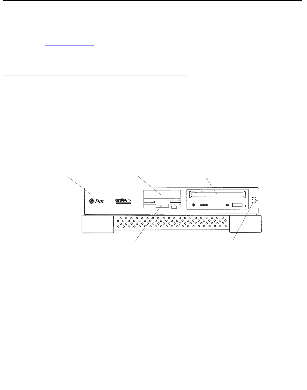
Factory hardware installation
190 Avaya CMS Sun Ultra 5 Computer Hardware Installation, Maintenance, and Troubleshooting
Preparing for factory hardware installation
This section includes the following:
●Computer layout on page 190
●ESD precautions on page 192
Computer layout
Familiarize yourself with the layout of the Ultra 5.
Front Panel
This figure shows the front panel of the Ultra 5. The diskette drive is not available if the
optional second internal hard drive has been installed.
System
unit
Diskette drive or second
internal hard drive
Standby
switch
CD-ROM
drive
3.5-inch bracket
(spare)
u5_front.cdr
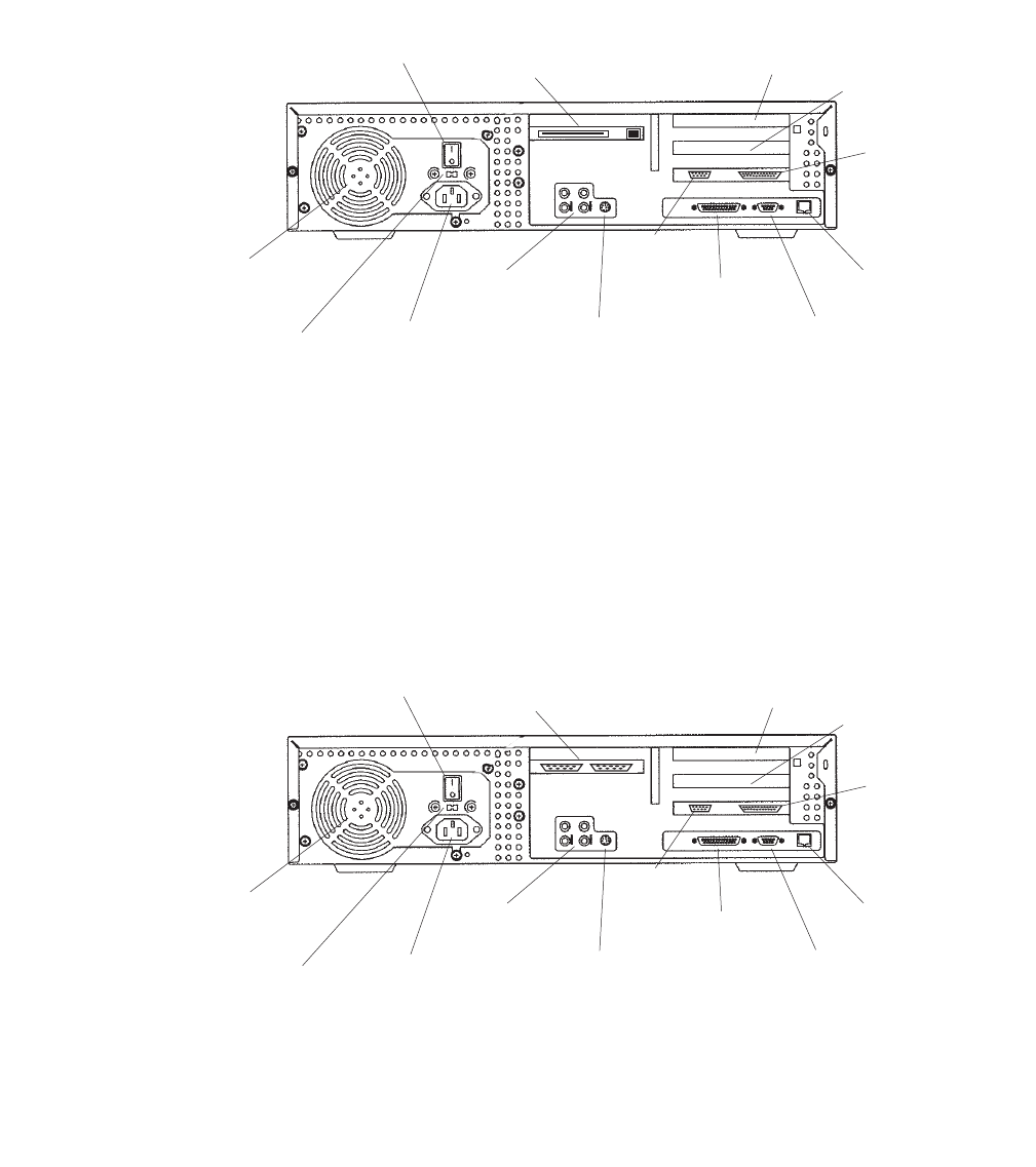
Preparing for factory hardware installation
Issue 3.3 February 2003 191
Rear Panel (with SunSwift card)
This figure shows the rear panel when you have a SunSwift card, which is usually installed
in PCI slot 2. The SunSwift card has one 68-pin SCSI connector and one ethernet RJ45
connector. Other PCI cards may be installed in slots 1 and 3.
Rear Panel (with UltraSCSI card)
This figure shows the rear panel when you have an UltraSCSI card, which is usually
installed in PCI slot 2. The UltraSCSI card has two 68-pin SCSI connectors. Other PCI
cards may be installed in slots 1 and 3.
Power
switch
SunSwift
card in
PCI slot 2
PCI
slot 3 PCI
slot 1
Parallel
printer
connector
Twisted-pair
ethernet
connector
VGA
connector
Serial
port A
Serial
port B
Keyboard
connector
Audio
connectors
Power cord
receptacle
Voltage selector
switch (older
models only)
Power
supply fan
u5_back_sunswift.cdr
Power
switch
(left)
UltraSCSI
card in
PCI slot 2
PCI
slot 3 PCI
slot 1
Parallel
printer
connector
Twisted-pair
ethernet
connector
VGA
connector
Serial
port A
Serial
port B
Keyboard
connector
Audio
connectors
Power cord
receptacle
Voltage selector
switch (older
models only)
Power
supply fan
u5_back_uscsi.cdr
(right)
(left)

Factory hardware installation
192 Avaya CMS Sun Ultra 5 Computer Hardware Installation, Maintenance, and Troubleshooting
ESD precautions
Before you work on components inside the Ultra 5 computer:
1. Make sure that the computer is plugged in to AC power.
2. Make sure that the power is off.
3. Attach the Electro-Static Discharge (ESD) wrist strap to the chassis frame and to your
wrist. See the following figure.
4. Unplug the AC power cord.
u5_wriststrap.cdr
PCI slot 2
screws

Installing an optional second internal hard drive
Issue 3.3 February 2003 193
Installing an optional second internal hard drive
This section describes how to add or replace the internal EIDE data disk drive in the Ultra 5
computer. The optional drive, together with hardware and a new ribbon cable, is packaged
separately from the Ultra 5 computer.
Note:
Note: In the following procedures, the disk drive that is already installed in the
Ultra 5 computer is referred to as the primary drive, and the new drive that
you install is referred to as the secondary drive.
Unpacking the disk drive
Remove the following items from the box that contains the secondary data disk drive and
place them in a convenient location:
●EIDE disk drive
●Mounting bracket
●Four pan head screws
●New EIDE ribbon cable
The new disk drive comes with two ribbon cables. The cable used with the Ultra 5 has
three connectors labeled SLAVE, MASTER, and MOTHERBOARD. The other cable
may be discarded.

Factory hardware installation
194 Avaya CMS Sun Ultra 5 Computer Hardware Installation, Maintenance, and Troubleshooting
Opening the computer
To open the computer:
1. If you have not already done so, use the following command to shut down the
computer:
/usr/sbin/shutdown -y -i0 -g0
2. Turn off the power to the computer.
3. Remove the two screws on the back of the unit that secure the cover to the chassis.
See the following figure.
4. Slide the cover back 1 or 2 inches and lift it up away from the chassis.
5. Place the cover in a convenient location so that it does not interfere with your work.
Cover Tabs
Cover
Screws
u5
_
remove
_
cover.cdr
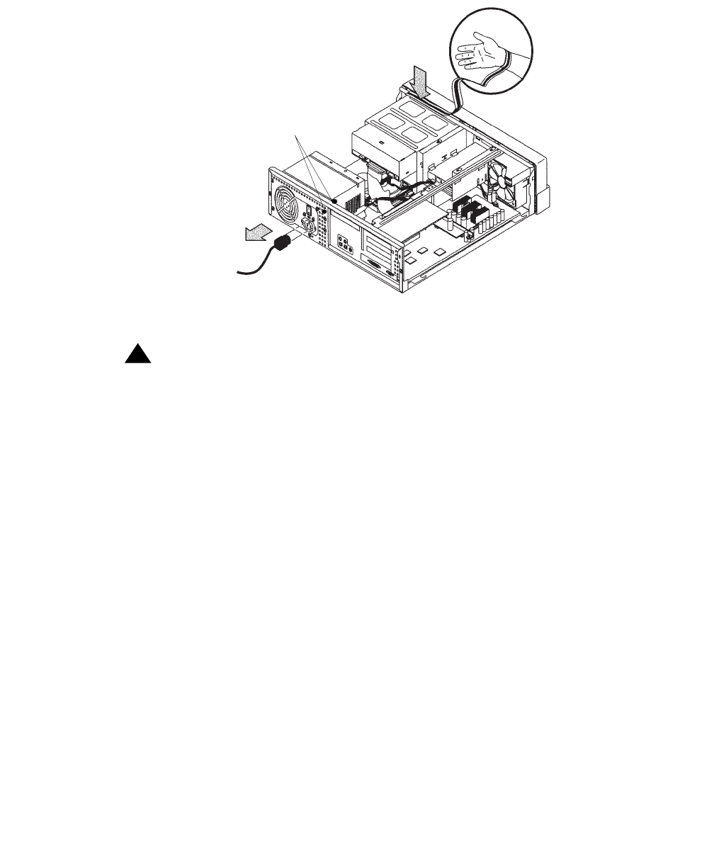
Installing an optional second internal hard drive
Issue 3.3 February 2003 195
6. Attach an antistatic wrist strap to the metal chassis of the computer and to your
wrist.See the following figure.
7. Disconnect the AC power cord.
!Important:
!Important:
Important: If the computer has a PCI card in slot position 2, you may want to remove
that card during this procedure to make it easier to reach the components.
To remove PCI card 2, you must first remove the PCI card 2 screw. On the
Series 1 computers, this screw is on the back of the computer. On Series 2
and later computers, this screw is on the top of the frame above the PCI
card.
u5_wriststrap.cdr
PCI slot 2
screws
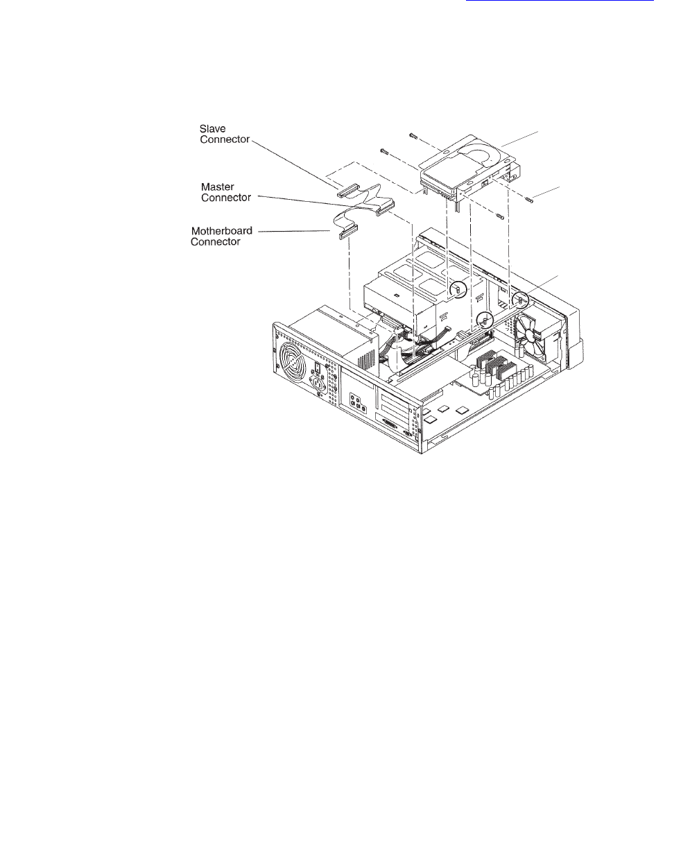
Factory hardware installation
196 Avaya CMS Sun Ultra 5 Computer Hardware Installation, Maintenance, and Troubleshooting
Removing the secondary internal disk drive
If there is no secondary internal disk drive, continue with Removing the diskette drive on
page 197.
To remove the secondary internal data disk drive:
1. Loosen but do not remove the three screws that secure the mounting bracket for the
secondary internal disk drive to the top of the chassis frame. See the following figure.
2. Remove the disk drive bracket from the chassis by sliding it back and lifting it free of
the three screws.
3. Disconnect the power cable from the secondary disk drive.
4. Lift out the mounting bracket and the attached disk drive.
5. Remove the four screws that hold the secondary internal disk drive to the mounting
bracket. Save the screws and mounting bracket for the new secondary internal disk
drive. Label the disk drive as the “Slave Disk,” and save it in case you have to reinstall
the original configuration.
Screw (4)
Secondary
disk drive
Screw (3)
u5_second_disk.cdr

Installing an optional second internal hard drive
Issue 3.3 February 2003 197
Removing the diskette drive
If there is no 3.5-inch internal diskette drive, continue with Installing new cabling on
page 198.
To remove the diskette drive:
1. Disconnect the power cable and diskette drive cable from the rear of the diskette drive.
See the following figure.
2. Loosen but do not remove the three screws that secure the diskette drive mounting
bracket to the top of the chassis frame.
3. Remove the diskette drive bracket from the chassis by sliding it back and lifting it free
of the three screws.
4. Lift out the mounting bracket and attached diskette drive.
5. At the motherboard, disconnect the diskette drive cable that comes from the diskette
drive.
6. Save the diskette drive and diskette drive cable in case you have to reinstall the
original configuration.
u5_diskette_cabling.cdr
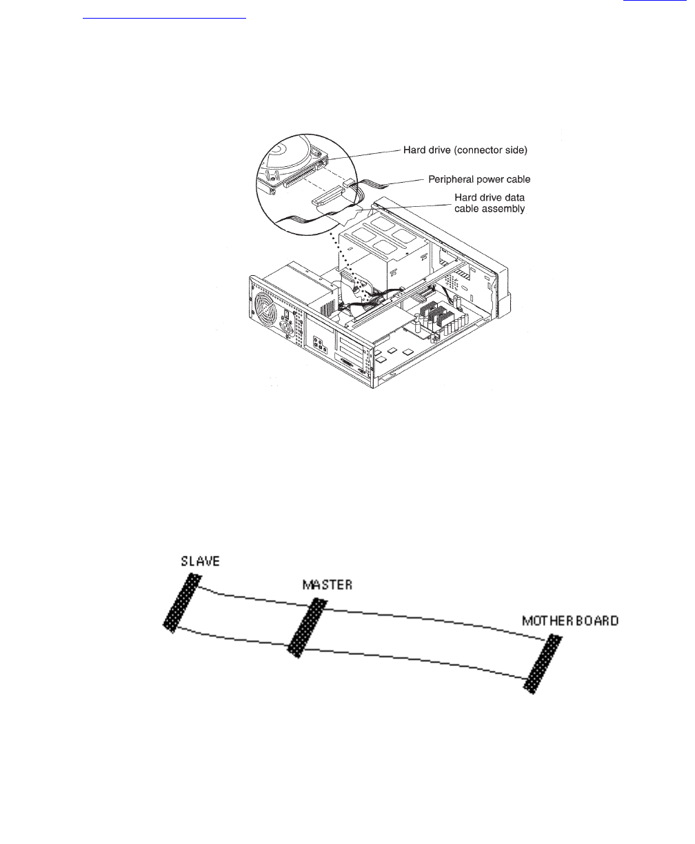
Factory hardware installation
198 Avaya CMS Sun Ultra 5 Computer Hardware Installation, Maintenance, and Troubleshooting
Installing new cabling
If the primary boot disk drive already has a new EIDE ribbon cable, continue with Installing
the secondary disk drive on page 199.
To install new cabling:
1. Remove the ribbon cable from the back of the primary disk drive. You may need to
remove the primary disk drive by removing the two screws securing the primary disk
drive bracket and lifting out the drive. See the following figure.
2. Remove the other end of this cable from the motherboard. Remember the slot in the
motherboard from which you remove this connector. You will install another connector
in this slot in the next step.
3. On the new ribbon cable that was supplied with the secondary disk drive, there are
three connectors labeled MOTHERBOARD, MASTER, and SLAVE. Insert the
connector labeled MOTHERBOARD into the slot in the motherboard from which you
removed a connector in the previous step. See the following figure.
4. Connect the connector labeled MASTER to the primary disk drive.
5. If you previously removed the primary disk drive, reinstall it on the chassis.
u5_master_cable.cdr
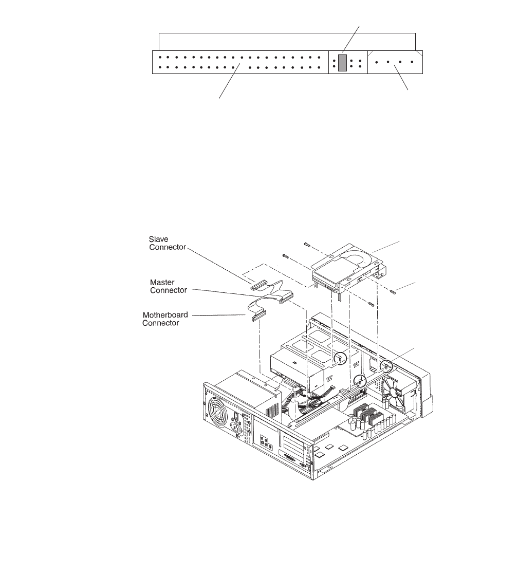
Installing an optional second internal hard drive
Issue 3.3 February 2003 199
Installing the secondary disk drive
To install the new secondary internal disk drive:
1. Ensure that the jumpers on the secondary internal hard drive are set to the Cable
Select (CS) setting. See the following figure.
2. Attach the secondary internal disk drive to the new mounting bracket with the four
screws from the old disk drive or from the new disk drive kit. Arrange the drive so that
the connectors point to the back of the computer.
Tip:
Tip: Install each screw with just a few turns before you tighten all four screws.
3. Connect the EIDE ribbon cable connector labeled SLAVE to the secondary internal
disk drive.
EIDE ribbon
cable connector
Jumper in
Cable Select (CS)
position
Power
connector
cable_sel.cdr
Screw (4)
Secondary
disk drive
Screw (3)
u5_second_disk.cdr

Factory hardware installation
200 Avaya CMS Sun Ultra 5 Computer Hardware Installation, Maintenance, and Troubleshooting
4. Connect the power cable to the secondary internal disk drive.
5. Install the mounting bracket for the secondary internal disk drive to the frame of the
chassis, slipping the three holes in the mounting bracket over the three screws in the
chassis frame.
6. Slide the mounting bracket forward as far as possible.
7. Tighten the three screws.
8. Route the cables to provide clearance.
Closing the computer
To close the computer:
1. If you removed the PCI card from Slot 2 earlier, reinstall it now.
2. Reconnect the AC power cord to the computer.
3. Detach the ESD wrist strap.
4. Replace the cover on the computer. Slide the cover forward until it fits snugly around
the chassis.
5. Replace the two cover screws.
Tip:
Tip: Install each screw with just a few turns before you tighten both screws.
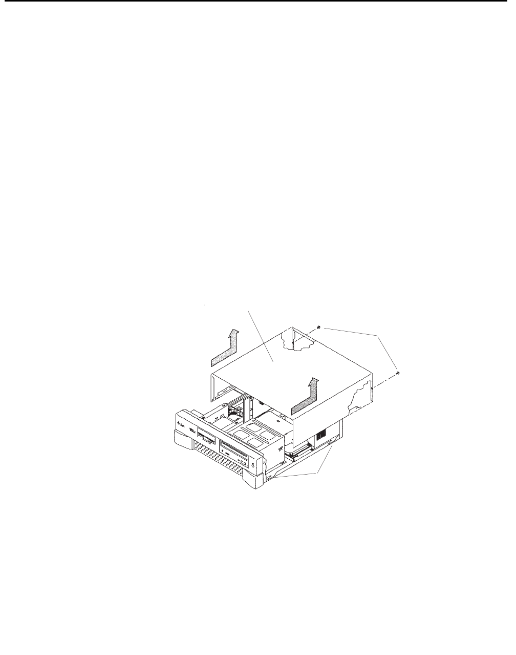
Installing memory
Issue 3.3 February 2003 201
Installing memory
Overview
The Ultra 5 comes equipped with one bank of dual inline memory modules (DIMMs) (256
MB) installed. If you need to install additional DIMMs, they must be installed in full banks
(pairs).
Opening the computer
To open the Ultra 5 computer:
1. If you have not already done so, enter the following command to shut down the
computer:
/usr/sbin/shutdown -y -i0 -g0
2. Turn off the power to the computer.
3. Remove the two screws on the back of the unit that secure the cover to the chassis.
See the following figure.
4. Slide the cover back 1 or 2 inches and lift it up away from the chassis.
5. Place the cover in a convenient location so that it does not interfere with your work.
Cover Tabs
Cover
Screws
u5
_
remove
_
cover.cdr
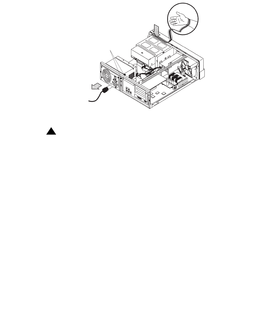
Factory hardware installation
202 Avaya CMS Sun Ultra 5 Computer Hardware Installation, Maintenance, and Troubleshooting
6. Attach an antistatic wrist strap to the metal chassis of the computer and to your wrist.
See the following figure.
7. Disconnect the AC power cord.
!Important:
!Important:
Important: If the computer has a PCI card in slot position 2, you must remove that card
during this procedure to make it easier to reach the components. To remove
PCI card 2, you must first remove the PCI card 2 screw. On the Series 1
computers, this screw is on the back of the computer. On Series 2 and later,
this screw is on top of the frame above the PCI card.
u5_wriststrap.cdr
PCI slot 2
screws

Installing memory
Issue 3.3 February 2003 203
Adding the memory modules
To add the memory modules:
1. Loosen the three screws that hold the diskette or second hard disk drive bracket and
move the disk drive out of the way.
The computer must have at least two identical DIMMs installed in paired sockets of any
DIMM bank. For best system performance, install four identical DIMMs. Install the
DIMMs as shown in the table below.
2. Remove the DIMM from the antistatic container.
3. Starting with the first empty slot, unlock (press down) the ejector levers at both ends of
the connectors.
4. Position the DIMM in the connector, ensuring that the notches on the bottom of the
DIMM are aligned with the connector alignment keys.
5. Press firmly on both of the top ends of the DIMM at the same time until the DIMM is
properly seated.
6. Verify that the ejection levers are closed toward the DIMM.
DIMM bank Slot pairs
0 DIMM1 and
DIMM2
1 DIMM3 and
DIMM4
Screws (3)
Ejection
Lever
Disk or
Diskette
Drive
u5_memory.cdr

Factory hardware installation
204 Avaya CMS Sun Ultra 5 Computer Hardware Installation, Maintenance, and Troubleshooting
7. Repeat this procedure for each DIMM.
8. Replace the diskette/disk drive bracket and tighten the screws that hold the bracket.
Closing the computer
To close the computer:
1. If you removed the PCI card from Slot 2 earlier, reinstall it now.
2. Reconnect the AC power cord to the computer.
3. Detach the ESD wrist strap.
4. Replace the cover on the computer. Slide the cover forward until it fits snugly around
the chassis.
5. Replace the two cover screws.
Tip:
Tip: Install each screw with just a few turns before you tighten both screws.
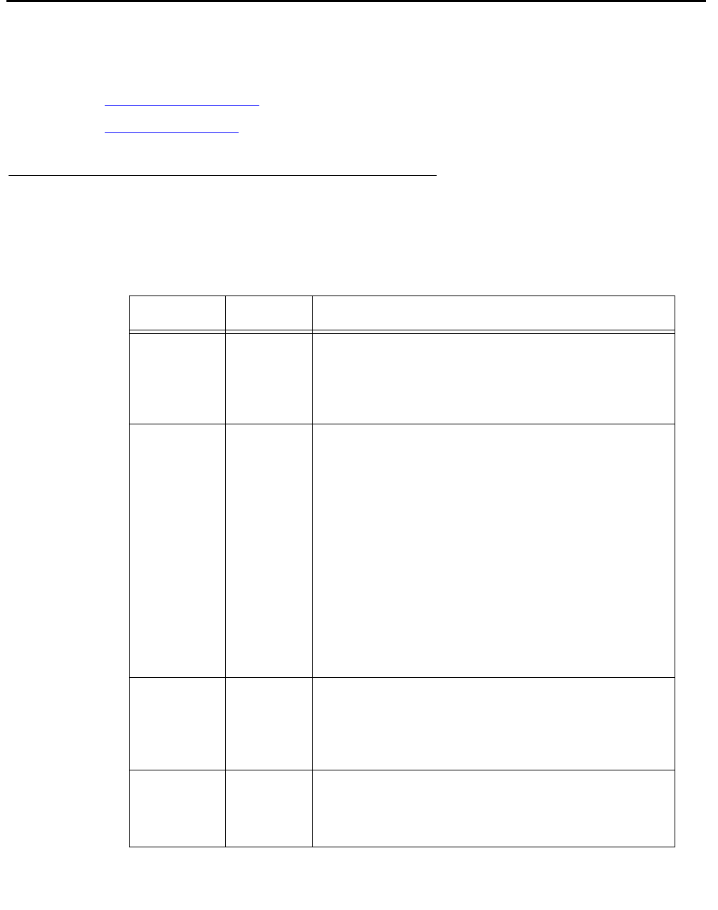
Installing PCI cards
Issue 3.3 February 2003 205
Installing PCI cards
This section consists of the following:
●PCI card configuration
●Installing PCI cards on page 206
PCI card configuration
Depending on your configuration, the PCI cards will be installed in the slots shown below.
Card PCI Slot Comments
SunSwift
or
UltraSCSI
PCI 2, 1,
or 3 Required. A SunSwift card is installed in every
computer to provide a dedicated ethernet
connection to the switch, and a SCSI interface to
external tape and disk drives. Additional SunSwift
cards can be installed in the other slots.
HSI/P PCI 1 or
PCI 3 Optional. HSI/P cards are not required when
using ethernet for switch link connectivity. Use
PCI 1 for the first card, which supports four ACDs.
Use PCI 1 and 3 for two cards, which support
eight ACDs.
Note:
Note: Some CMS loads do not support
the X.25 protocol. Contact the
National Customer Care Center or
consult with your product
distributor or representative to
verify if the X.25 protocol is
supported on your CMS system.
SAI/P PCI 1 or
PCI 3 Optional. SAI/P cards provide serial port
connectivity for printers and terminals. Use PCI 1
for the first card, which supports eight serial
devices. Use PCI 1 and 3 for two cards, which
supports 16 serial ports.
Token Ring PCI 3 Optional. Installation and setup of this card is
done by Professional Services in the United
States, or by special arrangement outside of the
United States.

Factory hardware installation
206 Avaya CMS Sun Ultra 5 Computer Hardware Installation, Maintenance, and Troubleshooting
Installing PCI cards
Use the following general instructions when installing, moving, and removing PCI cards.
Other sections in this chapter describe specific PCI card maintenance instructions. Use
those instructions as appropriate.
Note:
Note: If you plan to install an optional second internal hard drive, install it before
you install any PCI cards.
To install or remove a card:
1. For a system currently in operation, verify that you have a recent CMSADM file system
backup before you change card configurations.
2. Enter:
/usr/sbin/shutdown -y -i0 -g0
This shuts down the system.
3. Turn off the system.
4. Turn off the system monitor.
5. Turn off all external SCSI devices starting with the device closest to the system and
working toward the farthest device.
!WARNING:
WARNING: You must wear an ESD wrist strap when installing or removing hardware
components to prevent electrical discharge that can damage the system.
6. Remove the cover of the Ultra 5.
7. Disconnect the AC power cord.
8. Select an unused slot to add a card, or select what card you are removing.

Installing PCI cards
Issue 3.3 February 2003 207
9. Add or remove the card as shown in the following figure.
10. Remove the ESD wrist strap.
11. Reattach the cover.
12. Reconnect the AC power cord.
13. Turn on all external SCSI devices starting with the device farthest from the system and
working toward the system.
14. Turn on the system monitor.
15. Turn on the system.
16. Press Stop+A simultaneously after the console banner is displayed, but before the
system starts booting.
17. Enter:
boot -r
This reboots the system so that it recognizes the new configuration.
18. Perform a CMSADM file system backup to back up the updated system configuration.
See your CMS software installation, maintenance, and troubleshooting document for
details.
PCI card
Screw
PCI slot 1
PCI slot 3
PCI slot 2
u5_pcicard.cdr
PC riser
board

Factory hardware installation
208 Avaya CMS Sun Ultra 5 Computer Hardware Installation, Maintenance, and Troubleshooting

Issue 3.3 February 2003 209
Glossary
Automatic Call
Distribution (ACD) A switch feature. ACD is software that channels high-volume incoming call
traffic to agent groups (splits or skills).
Also an agent state where the extension is engaged in an ACD call (with the
agent either talking to the caller or the call waiting on hold).
Boot To load the system software into memory and start it running.
CMS Call Management System (CMS). A software product used by business
customers that have an Avaya telecommunications switch and receive a
large volume of telephone calls that are processed through the Automatic
Call Distribution (ACD) feature of the switch.
Data disk A nonboot disk.
DIMM Dual In-line Memory Module. A narrow printed circuit board that holds
memory chips. It plugs into a DIMM socket on the motherboard or memory
board.
EIDE Enhanced Integrated Drive Electronics
High Speed Serial
Interface/PCI (HSI/P) The HSI/P controller card is a 4-port serial communications PCI card. Each
of the four ports is used for a single physical X.25 link. It is an add-on
package that is needed by CMS for multiple ACDs.
Non-Volatile Random
Access Memory
(NVRAM)
A random access memory (RAM) system that holds its contents when
external power is lost.
PCI Bus The interface bus for the Sun Ultra 5 computer. Provides slots for additional
cards (for example, HSI Controller Card).
SCSI See Small Computer System Interface (SCSI).
SCSI Bus An industry standard peripheral bus that is used to connect intelligent
peripherals to a computer. It uses a daisy-chained cabling arrangement that
originates at the Host Adapter to interconnect up to seven intelligent
peripheral controllers on the bus. The Sun computer uses a fast SCSI-2
implementation.

SCSI ID
210 Avaya CMS Sun Ultra 5 Computer Hardware Installation, Maintenance, and Troubleshooting
SCSI ID Each tap on the SCSI bus is required to have a unique identification or
address, which is the SCSI ID. The ID is set by a target address switch
located on each device.
SCSI Single-Ended
Bus A version of the SCSI bus designed to minimize cost and space. Cable
lengths up to 6 meters are supported. A SCSI single-ended bus is not
compatible with the differential version of the SCSI bus.
SSO Services Support Organization. The Avaya organization that provides
technical support for Avaya products.
Slot An electronic connection designed to receive a module or a printed circuit
board (such as a SIMM or a frame buffer board).
Small Computer
System Interface
(SCSI)
A hardware interface that allows the connection of peripheral devices (such
as hard disks, tape drives and CD-ROM drives) to a computer system.

Issue 3.3 February 2003 211
Index
A
ACD switch link setup . . . . . . . . . . . . . . . 80
adding
external SCSI disk drives . . . . . . . . . . . . 102
memory . . . . . . . . . . . . . . . . . . . . 147
second internal disk drive . . . . . . . . . . 93, 193
tape drive . . . . . . . . . . . . . . . . . . . 138
tape drives. . . . . . . . . . . . . . . . 102, 138
ALT. . . . . . . . . . . . . . . . . . . . . . . . 189
assembly, load, and test . . . . . . . . . . . . . . 189
auto term high. . . . . . . 41, 43, 103, 105, 139, 141
auto term low . . . . . . . 41, 43, 103, 105, 139, 141
B
back panel . . . . . . . . . . . . . . . . . . 31, 190
C
CD-ROM . . . . . . . . . . . . . . . . . . 130, 177
drive failure . . . . . . . . . . . . . . . . . . 178
cleaning tape drives . . . . . . . . . . . . . . . . 136
clearances for service access . . . . . . . . . . . 24
Comsphere 3910 modem
installation . . . . . . . . . . . . . . . . . . . 38
options . . . . . . . . . . . . . . . . . . . . 52
configuring PCI cards . . . . . . . . . . . . . 65, 205
connecting
AC power cord . . . . . . . . . . . . . . . . . 33
external interfaces . . . . . . . . . . . . . . . 39
keyboard . . . . . . . . . . . . . . . . . . . 37
monitor . . . . . . . . . . . . . . . . . . . . 37
remote console modem. . . . . . . . . . . . . 38
SAI/P . . . . . . . . . . . . . . . . . . . . . 40
SCSI devices . . . . . . . . . . . . . . . . . 41
SCSI drives . . . . . . 41, 43, 103, 105, 139, 141
serial port expander box . . . . . . . . . . . . 40
switch link . . . . . . . . . . . . . . . . . . . 39
connectivity diagrams . . . . . . . . . . . . . 34, 35
console, redirecting
in OpenBoot mode . . . . . . . . . . . . . . . 157
with Solaris . . . . . . . . . . . . . . . . . . 154
CPU installation . . . . . . . . . . . . . . . . . . 147
customer support . . . . . . . . . . . . . . . . . 20
D
DDS4 tape drive. . . . . . . . . . . . . . . . . . 136
determining the computer model . . . . . . . . . . 29
disk drive
administration . . . . . . . . . . . . . . 122, 126
compatibility with CMS . . . . . . . . . . . . . 83
failure . . . . . . . . . . . . . . . . . . . . 178
maintenance . . . . . . . . . . . . . . . . . . 83
partition values . . . . . . . . . . . . . . . . .111
partitioning . . . . . . . . . . . . . . . . . . .117
documents. . . . . . . . . . . . . . . . . . . . . 12
E
electrical specifications . . . . . . . . . . . . . . . 24
environment . . . . . . . . . . . . . . . . . . . . 25
ESD precautions . . . . . . . . . . . . . . . 63, 192
expander box for SAI/P . . . . . . . . . . . . . . . 40
external interfaces . . . . . . . . . . . . . . . . . 39
external SCSI devices . . . . . . . . . . . . . . . 41
F
factory hardware installation procedures . . . . . . 189
front panel . . . . . . . . . . . . . . . . . . 31, 190
H
hardware
components . . . . . . . . . . . . . . . . . . 60
external SCSI devices. . . . . . . . . . . . . . 41
helplines. . . . . . . . . . . . . . . . . . . . . . 20
HSI card
installing
first card . . . . . . . . . . . . . . . . . . 78
second card. . . . . . . . . . . . . . . . . 81
software and patches . . . . . . . . . . . . 79
HSI/P card. . . . . . . . . . . . . . . . . 78, 79, 82
ACD switch links . . . . . . . . . . . . . . . . 80
I
identify PCI cards . . . . . . . . . . . . . . . . . 49
installation checklist . . . . . . . . . . . . . . . . 21
installing . . . . . . . . . . . . . . . . . . . . . . 78
CPU . . . . . . . . . . . . . . . . . . . . . 147
HSI software and patches . . . . . . . . . . . . 79
memory . . . . . . . . . . . . . . . . . 147, 201
PCI cards . . . . . . . . . . . . . . . . . . . 66
second internal disk drive . . . . . . . . . 93, 193

212 Avaya CMS Sun Ultra 5 Computer Hardware Installation, Maintenance, and Troubleshooting
K
keyboard commands . . . . . . . . . . . . . . . 173
L
LED status patterns . . . . . . . . . . . . . . . 174
local console. . . . . . . . . . . . . . . . . . . 156
loss of power . . . . . . . . . . . . . . . . . . 182
M
maintenance
adding, removing, or replacing tape drives . . . 138
cleaning tape drives. . . . . . . . . . . . . . 136
DDS4 tape drive . . . . . . . . . . . . . . . 136
disk drive administration. . . . . . . . . . 122, 126
disk drive partition values . . . . . . . . . . . .111
disk drive partitioning . . . . . . . . . . . . . .117
disk drives . . . . . . . . . . . . . . . . . . . 83
external SCSI disk drives . . . . . . . . . . . 102
HSI cards . . . . . . . . . . . . . . . . . . . 77
installing memory . . . . . . . . . . . . . . . 147
PCI cards . . . . . . . . . . . . . . . . . . . 64
removing a tape drive . . . . . . . . . . . . . 145
replacing an UltraSCSI card with a SunSwift card . 68
replacing the CD-ROM drive. . . . . . . . . . 130
replacing the primary internal EIDE boot disk drive 85
SAI/P cards . . . . . . . . . . . . . . . . . . 71
second internal disk drive . . . . . . . . . 93, 193
SLR5 tape drive . . . . . . . . . . . . . . . 137
tape drives . . . . . . . . . . . . . . . . 135, 138
memory . . . . . . . . . . . . . . . . . . . 147, 201
failure . . . . . . . . . . . . . . . . . . . . 172
memory installation. . . . . . . . . . . . . . . . 147
models of Ultra 5 computers . . . . . . . . . . . . 29
modem options
Comsphere 3910 . . . . . . . . . . . . . . . . 52
Sportster 33.6 . . . . . . . . . . . . . . . . . 50
moving an SAI/P card . . . . . . . . . . . . . . . 73
O
OpenBoot
diagnostic tests . . . . . . . . . . . . . . . . 169
PROM firmware tests . . . . . . . . . . . . . 164
redirecting the console . . . . . . . . . . . . 157
P
partitioning a disk drive . . . . . . . . . . . . . . .117
parts list . . . . . . . . . . . . . . . . . . . . 28, 36
PCI cards . . . . . . . . . . . . . . . . . 49, 64, 66
physical specifications. . . . . . . . . . . . . . . . 25
POST . . . . . . . . . . . . . . . . . . . . 46, 172
POST diagnostic messages . . . . . . . . . . . . 172
power cord . . . . . . . . . . . . . . . . . . . . . 33
power supply . . . . . . . . . . . . . . . . . . . . 33
power-up . . . . . . . . . . . . . . . . . . . . . . 46
precautions. . . . . . . . . . . . . . 22, 23, 63, 192
preparing for the installation . . . . . . . . . . . . . 22
preparing the environment. . . . . . . . . . . . . . 25
preserving data after a system failure . . . . . . . 182
probe command warnings . . . . . . . . . . . . . 184
probing devices. . . . . . . . . . . . . . . . . . 166
prtdiag command . . . . . . . . . . . . . . . . . 162
publications center . . . . . . . . . . . . . . . . . 12
R
recovery procedures . . . . . . . . . . . . . . . 182
keyboard becomes unplugged . . . . . . . . . 183
loss of power . . . . . . . . . . . . . . . . . 182
preserving data after a system failure . . . . . . 182
probe command warnings . . . . . . . . . . . 184
redirecting the console . . . . . . . . . . . . . . 154
in OpenBoot mode. . . . . . . . . . . . . . . 157
with Solaris . . . . . . . . . . . . . . . . . . 154
remote console
access . . . . . . . . . . . . . . . . . . . . 154
modem connectivity . . . . . . . . . . . . . . . 38
redirecting the port. . . . . . . . . . . . . . . 154
removing
SAI/P cards . . . . . . . . . . . . . . . . . . . 74
tape drive . . . . . . . . . . . . . . . . . . . 145
tape drives . . . . . . . . . . . . . . . 138, 145
replacing
external SCSI disk drives . . . . . . . . . . . 102
HSI/P card . . . . . . . . . . . . . . . . . . . 78
primary internal EIDE boot disk drive . . . . . . . 85
second internal disk drive . . . . . . . . . 93, 193
tape drives . . . . . . . . . . . . . . . . . . 138
UltraSCSI card with a SunSwift card . . . . . . . 68
reseating HSI/P cards . . . . . . . . . . . . . . . 185
S
safety precautions . . . . . . . . . . . . . . . . . 22
SAI/P
card
moving . . . . . . . . . . . . . . . . . . . 73
removing . . . . . . . . . . . . . . . . . . 74
expander box . . . . . . . . . . . . . . . . . . 40
SCSI devices

Issue 3.3 February 2003 213
daisy chaining . . . . . . . . . . . . . . . . . 41
installing/connecting . . . . . . . . . . . . . . 41
SunSwift. . . . . . . . . . . . . . . . . . . . 41
UltraSCSI . . . . . . . . . . . . . . . . . . . 43
SLR5 tape drive . . . . . . . . . . . . . . . . . . 137
specifications . . . . . . . . . . . . . . . . . 24, 25
Sportster 33.6 options . . . . . . . . . . . . . . . 50
Stop commands . . . . . . . . . . . . . . . . . . 173
Sun online Validation Test Suite (VTS) . . . . . . . 176
SunSwift . . . . . . . . . . . . . . . . 41, 103, 139
support . . . . . . . . . . . . . . . . . . . . . . 20
switch link. . . . . . . . . . . . . . . . . . . . . 39
system messages . . . . . . . . . . . . . . . . . 163
system precautions . . . . . . . . . . . . . . . . 23
T
tape drive . . . . . . . . . . . . . . . . . . . . . 138
adding or replacing . . . . . . . . . . . . . . . 138
cleaning . . . . . . . . . . . . . . . . . . . . 136
maintenance . . . . . . . . . . . . . . . . . . 135
removing . . . . . . . . . . . . . . . . . . . 145
troubleshooting. . . . . . . . . . . . . . . . . 179
target address switches . . 42, 45, 104, 107, 140, 143
technician support . . . . . . . . . . . . . . . . . 20
tools . . . . . . . . . . . . . . . . . . . . . 23, 161
troubleshooting
CD-ROM drive . . . . . . . . . . . . . . . . . 177
disk drives . . . . . . . . . . . . . . . . . . . 177
keyboard commands . . . . . . . . . . . . . . 173
LED status patterns . . . . . . . . . . . . . . 174
OpenBoot diagnostic tests . . . . . . . . . . . 169
OpenBoot PROM firmware tests . . . . . . . . 164
POST
diagnostic messages . . . . . . . . . . . . 172
preserve data after a system failure . . . . . . . 182
probe command warnings . . . . . . . . . . . 184
probing devices . . . . . . . . . . . . . . . . 166
prtdiag command. . . . . . . . . . . . . . . . 162
recovery procedures . . . . . . . . . . . . . . 182
remote console access . . . . . . . . . . . . . 154
Sun online Validation Test Suite (VTS) . . . . . 176
system messages . . . . . . . . . . . . . . . 163
tape drives. . . . . . . . . . . . . . . . . . . 179
tools. . . . . . . . . . . . . . . . . . . . . . 161
U
UltraSCSI . . . . . . . . . . . . . . . . 43, 105, 141
V
verifying POST. . . . . . . . . . . . . . . . . . . 46
voltage selector switch . . . . . . . . . . . . . . . 33

214 Avaya CMS Sun Ultra 5 Computer Hardware Installation, Maintenance, and Troubleshooting
