Avaya Bcm 4 0 Call Detail Recording System Users Manual BCM50 Administration Guide
2015-06-01
: Avaya Avaya-Bcm-4-0-Call-Detail-Recording-System-Users-Manual-735941 avaya-bcm-4-0-call-detail-recording-system-users-manual-735941 avaya pdf
Open the PDF directly: View PDF ![]() .
.
Page Count: 68
- Task list
- Contents
- Getting started
- Configuring Call Detail Recording
- Configuring and managing CDR data
- Call Detail Recording reports
- SL-1 reports
- Norstar reports
- Norstar report types
- Norstar Standard reports
- Norstar CLID reports
- Norstar Real-time report
- Norstar All report
- Auto Attendant and Call Center station set numbers
- Standard Hospitality record format
- Target line/physical lines
- Busy reports
- Bearer Capability data
- PRI call-by-call service
- Voice over IP calls
- Dialed number identification service
- Call connected digit separator
- External call forwarding
- Ad hoc multiparty conference calls
- Norstar report field definitions
- Real-time Hospitality record format
- Advice of charges at end of call
- Index

BCM 4.0
Business Communications Manager
Document Status: Standard
Document Version: 02
Part Code: N0060599
Date: June 2006
Call Detail Recording System Administration
Guide
Copyright © 2006 Nortel Networks, All Rights Reserved
All rights reserved.
The information in this document is subject to change without notice. The statements, configurations, technical data, and
recommendations in this document are believed to be accurate and reliable, but are presented without express or implied
warranty. Users must take full responsibility for their applications of any products specified in this document. The
information in this document is proprietary to Nortel Networks.
Trademarks
Nortel, the Nortel logo, and the Globemark are trademarks of Nortel Networks.
All other trademarks and registered trademarks are the property of their respective owners.

Task list 3
Call Detail Recording System Administration Guide
Task list
To configure Report Options .........................................................................................11
To assign the SL-1 report type ......................................................................................13
To assign Norstar report type ........................................................................................14
To assign the Date Format ............................................................................................14
To assign the Header Format........................................................................................15
To assign the Report Language ....................................................................................15
To assign Report Filters ................................................................................................15
To designate the feature code.......................................................................................16
To assign, change or delete Prefix Filters .....................................................................18
To configure CDR Report contents ...............................................................................18
To configure CDR Report File Settings .........................................................................22
To set up a CDR user account ......................................................................................26
To set Data Transfer type to Pull...................................................................................27
To install the CDR Pull Client ........................................................................................28
To start the CDR Pull Client ..........................................................................................28
To create a BCM List file ...............................................................................................29
To select the BCM List file.............................................................................................30
To add a BCM 4.0 system to the BCM List file..............................................................30
To change the connection information for a BCM 4.0 system on the BCM List file.......31
To remove a BCM 4.0 system from the BCM List file....................................................31
To schedule a Pull Transfer...........................................................................................31
To delete a Pull Transfer schedule................................................................................32
To read and reset transfer statistics ..............................................................................33
To schedule a data file transfer .....................................................................................34
To transfer the Call Detail Recording information immediately .....................................36
To install CDR Livestream.............................................................................................37
To access the CDR Livestream.....................................................................................38
To use the CDR Livestream ..........................................................................................38
To print records as you view them.................................................................................39

4Task list
N0060599N0060599

Contents 5
Call Detail Recording System Administration Guide
Contents
Chapter 1
Getting started . . . . . . . . . . . . . . . . . . . . . . . . . . . . . . . . . . . . . . . . . . . . . . . . . 7
About this guide . . . . . . . . . . . . . . . . . . . . . . . . . . . . . . . . . . . . . . . . . . . . . . . . . . . . . . . 7
System Administrator role . . . . . . . . . . . . . . . . . . . . . . . . . . . . . . . . . . . . . . . . . . . . 7
Audience . . . . . . . . . . . . . . . . . . . . . . . . . . . . . . . . . . . . . . . . . . . . . . . . . . . . . . . . . . . . 8
Acronyms . . . . . . . . . . . . . . . . . . . . . . . . . . . . . . . . . . . . . . . . . . . . . . . . . . . . . . . . . . . . 8
Symbols and conventions used in this guide . . . . . . . . . . . . . . . . . . . . . . . . . . . . . . . . . 8
Related publications . . . . . . . . . . . . . . . . . . . . . . . . . . . . . . . . . . . . . . . . . . . . . . . . . . . 9
How to get Help . . . . . . . . . . . . . . . . . . . . . . . . . . . . . . . . . . . . . . . . . . . . . . . . . . . . . . 10
Getting Help from the Nortel Web site . . . . . . . . . . . . . . . . . . . . . . . . . . . . . . . . . 10
Getting Help over the phone from a Nortel Solutions Center . . . . . . . . . . . . . . . . 10
Getting Help through a Nortel distributor or reseller . . . . . . . . . . . . . . . . . . . . . . . 10
Chapter 2
Configuring Call Detail Recording . . . . . . . . . . . . . . . . . . . . . . . . . . . . . . . . 11
Configuring CDR parameters . . . . . . . . . . . . . . . . . . . . . . . . . . . . . . . . . . . . . . . . . . . 11
Configuring Report Options . . . . . . . . . . . . . . . . . . . . . . . . . . . . . . . . . . . . . . . . . . . . . 11
Report formats and types . . . . . . . . . . . . . . . . . . . . . . . . . . . . . . . . . . . . . . . . . . . 13
Assigning the Date Format . . . . . . . . . . . . . . . . . . . . . . . . . . . . . . . . . . . . . . . . . . 14
Assigning the Header Format . . . . . . . . . . . . . . . . . . . . . . . . . . . . . . . . . . . . . . . . 14
Assigning the Report Language . . . . . . . . . . . . . . . . . . . . . . . . . . . . . . . . . . . . . . 15
Assigning Report Filters . . . . . . . . . . . . . . . . . . . . . . . . . . . . . . . . . . . . . . . . . . . . 15
Creating the Feature Code . . . . . . . . . . . . . . . . . . . . . . . . . . . . . . . . . . . . . . . . . . 16
Configuring the Prefix Filter . . . . . . . . . . . . . . . . . . . . . . . . . . . . . . . . . . . . . . . . . . 17
Configuring CDR Report contents . . . . . . . . . . . . . . . . . . . . . . . . . . . . . . . . . . . . . . . . 18
Configuring Leading Digits Suppression . . . . . . . . . . . . . . . . . . . . . . . . . . . . . . . . . . . 20
To assign or change Suppress Digits . . . . . . . . . . . . . . . . . . . . . . . . . . . . . . . . . . 20
Chapter 3
Configuring and managing CDR data . . . . . . . . . . . . . . . . . . . . . . . . . . . . . 21
Call Detail Recording security . . . . . . . . . . . . . . . . . . . . . . . . . . . . . . . . . . . . . . . . . . . 21
CDR User Group Administration . . . . . . . . . . . . . . . . . . . . . . . . . . . . . . . . . . . . . . 21
Configuring CDR Report File Settings . . . . . . . . . . . . . . . . . . . . . . . . . . . . . . . . . . . . . 22
Managing CDR data . . . . . . . . . . . . . . . . . . . . . . . . . . . . . . . . . . . . . . . . . . . . . . . . . . 24
Pull Transfer . . . . . . . . . . . . . . . . . . . . . . . . . . . . . . . . . . . . . . . . . . . . . . . . . . . . . 24
Push Transfer . . . . . . . . . . . . . . . . . . . . . . . . . . . . . . . . . . . . . . . . . . . . . . . . . . . . 24
Real-time data . . . . . . . . . . . . . . . . . . . . . . . . . . . . . . . . . . . . . . . . . . . . . . . . . . . . 25
Features of Data File Transfer . . . . . . . . . . . . . . . . . . . . . . . . . . . . . . . . . . . . . . . 25
Using CDR Pull Transfer . . . . . . . . . . . . . . . . . . . . . . . . . . . . . . . . . . . . . . . . . . . . . . . 25

6Contents
N0060599N0060599
Starting the CDR Pull Client . . . . . . . . . . . . . . . . . . . . . . . . . . . . . . . . . . . . . . . . . 28
Configuring the BCM List file . . . . . . . . . . . . . . . . . . . . . . . . . . . . . . . . . . . . . . . . . 29
Configuring the systems on the BCM List file . . . . . . . . . . . . . . . . . . . . . . . . . . . . 30
Scheduling a Pull Transfer . . . . . . . . . . . . . . . . . . . . . . . . . . . . . . . . . . . . . . . . . . 31
Exiting from the CDR Pull Client . . . . . . . . . . . . . . . . . . . . . . . . . . . . . . . . . . . . . . 32
Using CDR Push Transfer . . . . . . . . . . . . . . . . . . . . . . . . . . . . . . . . . . . . . . . . . . . . . . 33
Transferring Call Detail Recording information immediately . . . . . . . . . . . . . . . . . 36
Using CDR Livestream . . . . . . . . . . . . . . . . . . . . . . . . . . . . . . . . . . . . . . . . . . . . . . . . 37
Call Detail Recording display . . . . . . . . . . . . . . . . . . . . . . . . . . . . . . . . . . . . . . . . . . . . 38
Chapter 4
Call Detail Recording reports . . . . . . . . . . . . . . . . . . . . . . . . . . . . . . . . . . . . 41
SL-1 reports . . . . . . . . . . . . . . . . . . . . . . . . . . . . . . . . . . . . . . . . . . . . . . . . . . . . . . . . . 41
SL-1 report types . . . . . . . . . . . . . . . . . . . . . . . . . . . . . . . . . . . . . . . . . . . . . . . . . . 41
SL-1 report field definitions . . . . . . . . . . . . . . . . . . . . . . . . . . . . . . . . . . . . . . . . . . 41
SL-1 Standard reports . . . . . . . . . . . . . . . . . . . . . . . . . . . . . . . . . . . . . . . . . . . . . . 43
SL-1 CLID reports . . . . . . . . . . . . . . . . . . . . . . . . . . . . . . . . . . . . . . . . . . . . . . . . . 43
Auto Attendant and Call Center station set numbers . . . . . . . . . . . . . . . . . . . . . . 44
Advice of charges at end of call (AOCE) . . . . . . . . . . . . . . . . . . . . . . . . . . . . . . . . 44
Norstar reports . . . . . . . . . . . . . . . . . . . . . . . . . . . . . . . . . . . . . . . . . . . . . . . . . . . . . . . 45
Norstar report types . . . . . . . . . . . . . . . . . . . . . . . . . . . . . . . . . . . . . . . . . . . . . . . 45
Norstar Standard reports . . . . . . . . . . . . . . . . . . . . . . . . . . . . . . . . . . . . . . . . . . . . 46
Norstar CLID reports . . . . . . . . . . . . . . . . . . . . . . . . . . . . . . . . . . . . . . . . . . . . . . . 46
Norstar Real-time report . . . . . . . . . . . . . . . . . . . . . . . . . . . . . . . . . . . . . . . . . . . . 47
Norstar All report . . . . . . . . . . . . . . . . . . . . . . . . . . . . . . . . . . . . . . . . . . . . . . . . . . 49
Auto Attendant and Call Center station set numbers . . . . . . . . . . . . . . . . . . . . . . 49
Standard Hospitality record format . . . . . . . . . . . . . . . . . . . . . . . . . . . . . . . . . . . . 49
Target line/physical lines . . . . . . . . . . . . . . . . . . . . . . . . . . . . . . . . . . . . . . . . . . . . 50
Busy reports . . . . . . . . . . . . . . . . . . . . . . . . . . . . . . . . . . . . . . . . . . . . . . . . . . . . . 50
Bearer Capability data . . . . . . . . . . . . . . . . . . . . . . . . . . . . . . . . . . . . . . . . . . . . . . 51
PRI call-by-call service . . . . . . . . . . . . . . . . . . . . . . . . . . . . . . . . . . . . . . . . . . . . . 51
Voice over IP calls . . . . . . . . . . . . . . . . . . . . . . . . . . . . . . . . . . . . . . . . . . . . . . . . . 52
Dialed number identification service . . . . . . . . . . . . . . . . . . . . . . . . . . . . . . . . . . . 52
Call connected digit separator . . . . . . . . . . . . . . . . . . . . . . . . . . . . . . . . . . . . . . . . 53
External call forwarding . . . . . . . . . . . . . . . . . . . . . . . . . . . . . . . . . . . . . . . . . . . . . 53
Ad hoc multiparty conference calls . . . . . . . . . . . . . . . . . . . . . . . . . . . . . . . . . . . . 54
Norstar report field definitions . . . . . . . . . . . . . . . . . . . . . . . . . . . . . . . . . . . . . . . . 55
Real-time Hospitality record format . . . . . . . . . . . . . . . . . . . . . . . . . . . . . . . . . . . . 60
Advice of charges at end of call . . . . . . . . . . . . . . . . . . . . . . . . . . . . . . . . . . . . . . 61
7
Call Detail Recording System Administration Guide
Chapter 1
Getting started
This section contains information on the following topics:
•“About this guide” on page 7
•“Symbols and conventions used in this guide” on page 8
•“Symbols and conventions used in this guide” on page 8
•“Related publications” on page 9
•“How to get Help” on page 10
About this guide
This guide tells a System Administrator how to configure the Call Detail Recording (CDR)
application, generate reports, and install and use the CDR Pull Client and CDR Livestream.
System Administrator role
The System Administrator performs the initial and ongoing administration tasks.
Your tasks include:
• administering CDR
• determining Account codes used as references for tracking telephone calls
• interpreting reports
Warning: SECURITY ALERT: CDR records the date and time of calls, digits dialed,
incoming call information and time elapsed. This can include sensitive and personal
information such as telephone banking numbers, credit card numbers, and personal
identification numbers. Digits dialed are not maintained as confidential.
As System Administrator, it is solely your responsibility to advise users that their
telephone dialing information can be monitored and recorded.
Further, LAN-based access to call records (passive or real-time) demands a greater
emphasis on call record security. Limitations and security arrangements can vary
depending on the network environment and how a customer administers and limits access
to call records. Consult with the appropriate members of your organization about the
proper safeguards.
8Chapter 1 Getting started
N0060599N0060599
Audience
This guide is intended for people who install and configure the Multimedia Contact Center
application. This guide assumes that you are familiar with using Element Manager and CallPilot
Manager. For more information, refer to the BCM 4.0 Administration Guide (N0060598) and the
CallPilot Manager Set Up and Operations Guide (N0027247).
Acronyms
The following is a list of acronyms used in this guide.
Symbols and conventions used in this guide
These symbols are used to highlight critical information:
Table 1
Acronym Description
BCM Business Communications Manager
CCR Custom Call Routing
CLID Calling line identification
PIN Personal identification number
Caution: Alerts you to conditions where you can damage the equipment.
Danger: Alerts you to conditions where you can get an electrical shock.
Warning: Alerts you to conditions where you can cause the system to fail or work
improperly.
Note: A Note alerts you to important information.
Tip: Alerts you to additional information that can help you perform a task.

Chapter 1 Getting started 9
Call Detail Recording System Administration Guide
Related publications
Related publications are listed below. To locate specific information, you can refer to the
Master Index of BCM 4.0 Library.
BCM 4.0 Administration Guide (N0060598)
CallPilot Manager Set Up and Operation Guide (N0027247)
!
Security note: Indicates a point of system security where a default should be changed,
or where the administrator needs to make a decision about the level of security required
for the system.

10 Chapter 1 Getting started
N0060599N0060599
How to get Help
This section explains how to get help for Nortel products and services.
Getting Help from the Nortel Web site
The best source of support for Nortel products is the Nortel Support Web site:
http://www.nortel.com/support
This site enables customers to:
• download software and related tools
• download technical documents, release notes, and product bulletins
• sign up for automatic notification of new software and documentation
• search the Support Web site and Nortel Knowledge Base
• open and manage technical support cases
Getting Help over the phone from a Nortel Solutions Center
If you have a Nortel support contract and cannot find the information you require on the
Nortel Support Web site, you can get help over the phone from a Nortel Solutions Center.
In North America, call 1-800-4NORTEL (1-800-466-7865).
Outside North America, go to the Web site below and look up the phone number that applies
in your region:
http://www.nortel.com/callus
When you speak to the phone agent, you can reference an Express Routing Code (ERC) to more
quickly route your call to the appropriate support specialist. To locate the ERC for your product or
service, go to:
http://www.nortel.com/erc
Getting Help through a Nortel distributor or reseller
If you purchased a service contract for your Nortel product from a distributor or authorized
reseller, you can contact the technical support staff for that distributor or reseller.
11
Call Detail Recording System Administration Guide
Chapter 2
Configuring Call Detail Recording
The CDR application collects many different kinds of information for CDR data files:
• date and time of external calls
• Hunt Group usage statistics
• Custom Call Routing (CCR) tree reports
• mailbox activity reports
Configuring CDR parameters
You can configure CDR parameters to specify what call information is presented in your reports.
This section describes:
•“Configuring Report Options” on page 11
•“Assigning Report Filters” on page 15
•“Configuring the Prefix Filter” on page 17
•“Configuring CDR Report contents” on page 18
•“Configuring Leading Digits Suppression” on page 20
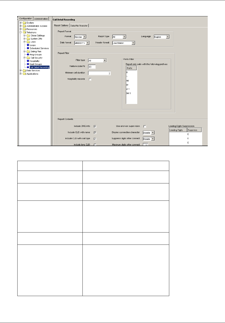
Configuring Report Options
To configure Report Options
1Log on to Element Manager.
2On the Task Navigation Panel, click the Configuration tab.
The Configuration folders appear.
3Select the Telephony folder.
4Click Call Detail Recording.
The Call Detail Recording panel appears with the Report Options tab displayed.
5Use the tables in the Report Options tab to configure your report options.
6Specify your report format and contents, and the filters you want to use.
Note: For detailed information on mailbox activity reports, refer to the CallPilot
Manager Set Up and Operation Guide (N0027247).
12 Chapter 2 Configuring Call Detail Recording
N0060599N0060599
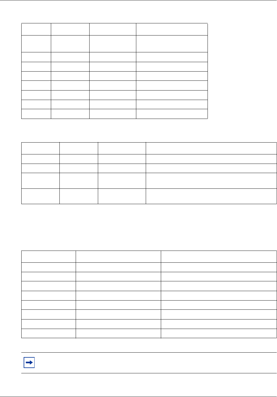
Figure 1 The Report Options page
Table 1 Report Options
Parameter Options
Format SL-1
Norstar
Date format MM/DD/YY
DD/MM/YY
YY/MM/DD
Report type SL-1 Standard
SL-1 CLID
Norstar Standard
Norstar CLID
Norstar Real-time
Norstar All
Header format Line/Station
Source/Destination
Language English
French
Danish
Swedish
Dutch
Spanish
German
Italian
Norwegian
Portuguese
Chapter 2 Configuring Call Detail Recording 13
Call Detail Recording System Administration Guide
Report formats and types
Call Detail Recording can generate Norstar and SL-1 report types. SL-1 offers two report formats:
Standard and CLID. Norstar offers four report formats: Standard, CLID, Real-time, and All.
SL-1 reports
Use the SL-1 report format when you are supplying the CDR output to legacy commercial
call accounting packages or equipment.
This report format supports recording Standard report type as well as the Calling Line
Identification (CLID) report type.
The SL-1 CLID report prints the CLID information only if the information is delivered. Otherwise,
it records the call in SL-1 Standard report type.
The SL-1 report format does not support the recording of Bearer Capability and DDI Busy reports.
To assign the SL-1 report type
From the Report Options page, you can assign the SL-1 report type as Standard or CLID.
1On the Task Navigation Panel, click the Configuration tab.
The Configuration folders appear.
2Select the Telephony folder and click the Call Detail Recording task.
The Call Detail Recording panel appears with the Report Options tab displayed.
3From the Format drop-down list, select SL-1.
4From the Report Type drop-down list, select Standard or CLID.
Norstar reports
Use the Norstar report format for more detailed call reports.
Note: The default report format is Norstar and the default report type is All.
Note: For more information about SL-1 reports, see “SL-1 reports” on page 41.
Note: CDR reports only the CLID information for lines that are capable of delivering
CLID. Calls on lines that are non-CLID capable are reported in SL-1 Standard report
format.
Note: For more information about Norstar reports, see “Norstar reports” on page 45.

14 Chapter 2 Configuring Call Detail Recording
N0060599N0060599
Assign the Norstar report type
From the Report Options page, you can assign the Norstar report type as Standard, CLID,
Real-time or All.
To assign Norstar report type
1On the Task Navigation Panel, click the Configuration tab.
The Configuration folders appear.
2Select the Telephony folder and click the Call Detail Recording task.
The Call Detail Recording panel appears with the Report Options tab displayed.
3From the Format list, select Norstar.
4From the Report Type list, select Standard, CLID, Real-time or All.
Assigning the Date Format
The Date Format includes the day, month and year. There are three date formats:
•MM/DD/YY
• DD/MM/YY
• YY/MM/DD
The default date format is MM/DD/YY. This parameter affects only the Norstar Record Format.,
and is intended to provide market compatibility.
To assign the Date Format
1On the Task Navigation Panel, click the Configuration tab.
The Configuration folders appear.
2Select the Telephony folder and click the Call Detail Recording task.
The Call Detail Recording panel appears with the Report Options tab displayed.
3From the Date Format drop-down list, select MM/DD/YY, DD/MM/YY or YY/MM/DD.
Assigning the Header Format
There are two kinds of header formats: Line/Station and Source/Destination. The default Header
Format is Line/Station. This parameter applies to the Norstar Record Format only.
The Line/Station format always reports the line number followed by the station number. The
Source/Destination format always reports the number placing the call followed by the number
receiving the call. Incoming calls are reported in the Line/Station format. Outgoing calls are
reported in the Station/Line format.

Chapter 2 Configuring Call Detail Recording 15
Call Detail Recording System Administration Guide
To assign the Header Format
1On the Task Navigation Panel, click the Configuration tab.
The Configuration folders appear.
2Click the Telephony folder and click the Call Detail Recording task.
The Call Detail Recording panel appears with the Report Options tab displayed.
3From the Header Format list box, select Line/Station or Source/Destination.
Assigning the Report Language
If your BCM 4.0 supports other languages, select either English or one of the alternate languages.
The default Report Language is English.
To assign the Report Language
1On the Task Navigation Panel, click the Configuration tab.
The Configuration folders appear.
2Click the Telephony folder and click the Call Detail Recording task.
The Call Detail Recording panel appears with the Report Options tab displayed.
3From the Language list box, select English or an alternate language.
Assigning Report Filters
Use the Report Filters to specify the type of calls to collect. You can select only one filter type at a
time. The default report filter is All.
To assign Report Filters
1On the Task Navigation Panel, click the Configuration tab.
The Configuration folders appear.
2Click the Telephony folder and click the Call Detail Recording task.
The Call Detail Recording panel appears with the Report Options tab displayed.
3In the Report Filter option, select All, Outgoing, Prefix or Account Code.
4In the minimum call duration box, enter the minimum call duration number.
The range is 0 to 30 seconds.
Note: The Report Language you select affects only CDR reports. The language assigned
to each telephone determines the language used in the Account codes.

16 Chapter 2 Configuring Call Detail Recording
N0060599N0060599
5Select the Hospitality records check box, if you require hospitality records.
Creating the Feature Code
The purpose of the feature code is to allow a user to enter an account code when on a call. The
account code that is entered is registered and recorded in the BCM CDR record for that call.
The default feature code in BCM is 900. If 900 is being used for another application, you can
choose another code to represent CDR. The feature code you designate can be any unused number
between 900 and 999. You designate the feature code in Element Manager.
To designate the feature code
1On the Task Navigation Panel, click the Configuration tab.
The Configuration folders appear.
2Click the Telephony folder and click the Call Detail Recording task.
The Call Detail Recording panel appears with the Report Options tab displayed.
3In the Feature Code field, enter a number between 00 and 99. The first digit (9) is provided.
Callers can now enter the Feature Code and then enter the appropriate Account Codes.
Report Filter Description
Filter type All reports all incoming and outgoing calls.
Outgoing reports only outgoing calls (no incoming calls).
Prefix reports calls matching the predetermined long distance digit strings.
The purpose of the Prefix filter is to report only long distance calls, calls to certain
area codes, or calls to specific numbers. If you select the Prefix Report filter, you
must also specify the prefix digits.
If the first digits dialed match one or more of the programmable prefix strings, the call
is reported; otherwise the call is not reported. You can have a maximum of eight
prefix strings assigned at one time. The maximum length for each prefix string is
eight digits.
Note: The Prefix filter defaults are 0, 1, 90, 91, 411 and 9411. Invalid Password
attempts are reported regardless of the Report Filter selected.
Account code reports only calls that have account codes associated with them.
Feature code F9 See “Creating the Feature Code”.
Minimum call
duration
This filter determines which calls are included in the CDR. Calls shorter than the
minimum call duration are not logged. The default setting is 2 seconds and the range
is 0 - 30 seconds.
Hospitality records This filter represents four states of room occupancy: vacant, basic, mid and full.
Room number lengths can be 1 - 5 digits.
Chapter 2 Configuring Call Detail Recording 17
Call Detail Recording System Administration Guide
Account Codes
With Account Codes you can track telephone calls from your company to different clients or for
telephone activities. For example, a caller contacting a billable client can enter an account code
each time they call that client.
Callers can enter account codes for any incoming or outgoing calls. Callers enter the feature code
(F9--) followed by the account code.
Callers can enter an account code any time during an active call. They cannot enter an Account
Code when a call is on hold or when a configuration session is in progress.
Account Code list
Account Codes have a maximum of 12 digits but cannot contain symbols such as (*) or (#). Table
2 is an example of an Account Code list.
Configuring the Prefix Filter
With the Prefix Filter, you can select whether you monitor and report all long-distance calls, only
calls to certain area codes, or calls to specific numbers.
If the first digits a caller dials match one or more of the prefixes you have defined, the call is
reported. Otherwise the call is not reported. You can have a maximum of eight prefix strings
assigned at one time. The maximum length for each prefix string is eight digits. The Prefix filter
default settings are 0, 1, 90, 91, 411 and 9411.
Note: Remember to provide your colleagues with the Feature Code and the
Account Code list. Your Account Code list is not stored on the BCM. The BCM
does not check that account code is valid.
Table 2 Account Codes
Account code Description
11127 Pat (manager)
37 Field Support
239 Liza (Sales)
45 Roger (Service)
1552 Monique (Shipping)
53 Modern Ways Limited
100 Long distance

18 Chapter 2 Configuring Call Detail Recording
N0060599N0060599
To assign, change or delete Prefix Filters
1On the Task Navigation Panel, click the Configuration tab.
The Configuration folders appear.
2Click the Telephony folder and click the Call Detail Recording task.
The Call Detail Recording panel appears with the Report Options tab displayed.
3In the prefix filter table, in the Prefix 1 list box, enter the prefix number.
4In the Prefix 2 through Prefix 8 list boxes, enter the prefix numbers as required.
5To modify an existing prefix, select the prefix and change it to the appropriate value.
6To delete an existing prefix, select the prefix and delete all of the digits.
Configuring CDR Report contents
To configure CDR Report contents
1On the Task Navigation Panel, click the Configuration tab.
The Configuration folders appear.
2Click the Telephony folder and click the Call Detail Recording task.
The Call Detail Recording panel appears with the Report Options tab displayed.
The report contents appear in the lower panel.
Table 3 Report contents
Option Description (default shown in bold)
Include DNIS Info Yes/No
Provides the number the caller dialed to reach the BCM 4.0 system.
You can enable or disable the DNIS Info parameter. This parameter applies
to the Norstar Record Format only. Do not change the default unless the
trunk supports this feature.
Include CLID with name Yes/No
Reports the CLID name of each call. You can enable or disable this
parameter at any time. This parameter applies to the Norstar Record Format
only. Do not change the default unless the trunk supports this feature.
Include CLID with call type Yes/No
Supports long distance or unknown call types. This parameter applies to the
Norstar Record Format only. Do not change the default unless the trunk
supports this feature.
Include long CLID Yes/No
Supports long CLID digit reporting. This parameter is market-specific. Do
not change the default unless the trunk supports this feature.

Chapter 2 Configuring Call Detail Recording 19
Call Detail Recording System Administration Guide
Include call charge info Yes/No
Supports charges on calls. This parameter is market-specific. Do not
change the default unless the trunk supports this feature.
Use answer supervision Yes/No
Identifies the telephone number answering outgoing calls. This parameter is
market-specific. Do not change the default unless the trunk supports this
feature.
Display connection character Enable/Disable
Normally, CDR reports all the digits the user dialed to connect a call. The
digits can include digits responding to prompts from an Auto-attendant,
extension transfer or voice mail service. To distinguish between digits dialed
to connect the call and digits dialed after the call is connected, the system
inserts an “!” between the two sets of digits. (For Norstar report format only.)
You can enable or disable the display connection character parameter.
Suppress digits after connect
Maximum digits after connect
Enable/Disable
By default, CDR stores all digits dialed, even after the call has been
answered. This includes any personal information dialed, such as account
numbers, credit card numbers or PINs. You can use the Digit Suppression
feature to stop CDR from storing digits after the call has been answered.
To configure the Suppress digits feature, use the Suppress digits after
connect and Maximum digits after connect options. With Suppress digits
after connect you can enable or disable this feature. With Maximum digits
after connect you specify the maximum number of digits CDR stores.
How the Suppress digits operates:
•If Suppress digits after connect is disabled
CDR records all of the digits dialed.
Line Supervision and the Maximum digits after connect have no affect if
Suppress digits is disabled.
•If Suppress digits after connect is enabled and Line Supervision is
available on the line used
CDR records the telephone number dialed, but stops recording when
Line Supervision indicates the call is answered.
The Maximum digits after connect option has no affect if Line
Supervision is available on the line used.
•If Suppress Digits after connect is enabled and Line Supervision is
not available on the line used
CDR records the digits dialed until it reaches the number entered in the
Maximum digits after connect box. After this number of digits is
recorded, CDR stops recording digits.
In the Maximum digits after connect box, enter the maximum number of
digits that CDR stores, from 3 to 24. The default is 11.
Caution: Some of the Report Options are market-specific. If the parameter value does not
match the trunk property, CDR can produce incorrect reports. Changing the parameters
can affect some Suppress Digit parameters. If you use a Call Accounting package to
process reports, consult your software vendor before you make any changes.
Table 3 Report contents

20 Chapter 2 Configuring Call Detail Recording
N0060599N0060599
Configuring Leading Digits Suppression
You can configure CDR so that personal identification numbers (PIN) that callers use to access
long-distance carriers are not recorded in CDR. Usually the long-distance caller dials the code of
their carrier (up to five digits), enters a PIN (0 to 16 digits), and then enters the long-distance
telephone number. Leading Digits Suppression provides security to long-distance callers by
preventing PINs being recorded in the reports.
You can define a maximum of five Leading Digit strings. The first digits that a caller dials are
compared to the Leading Digits. If there is a match, a number of digits are suppressed. (The
number of digits that are suppressed equals the number you select in the Suppress field for the
string). Only the code of the carrier and the remaining digits (excluding the PIN) are printed in the
output report.
To assign or change Suppress Digits
1On the Task Navigation Panel, click the Configuration tab.
The Configuration folders appear.
2Click the Telephony folder and click the Call Detail Recording task.
The Call Detail Recording panel appears with the Report Options tab displayed.
3On the lower panel, in the Leading Digits Suppression table, in the Leading Digits box enter
the carrier code.
The carrier code can be up to five digits long, and is the number that users must dial to reach
their carrier. For example, users must dial 3421 to reach their long-distance carrier.
4In the Suppress box, select the number of digits, up to a maximum of 16, that callers can have
in their PIN.
21
Call Detail Recording System Administration Guide
Chapter 3
Configuring and managing CDR data
This section contains information on:
• Call Detail Recording (CDR) security
• CDR data management and configuration
Call Detail Recording security
CDR records can contain sensitive information, such as phone numbers between executives and
external companies, telephone banking passwords and PINs. These are some examples of data that
require protection from unauthorized access. With the introduction of network real-time access in
Call Detail Recording, the System Administrator must set up the system to allow authorized
access. If authorized access is not set up, the user cannot see the real-time records.
To set up CDR, you must log on to the BCM Element Manager with a user name and password
that is a member of the Admin Group. Once logged on, you can add members to the CDR User
Group. Only members of the CDR User Group can access the records. Members of other User
Groups, including the Admin User Group, cannot access the Call Detail Recording records.
CDR User Group Administration
By default, the CDR User Group has no members. The System Administrator can add users to the
CDR User Group through Element Manager. The System Administrator can also modify user
access privileges or delete existing usernames from the group.
For information about how to add, delete and modify users and User Groups, refer to the BCM 4.0
Administration Guide (N0016868).
Caution: To guard against unauthorized access to CDR records, you must add
only authorized users to the CDR User Group. In this configuration, the BCM
security protects all records against unauthorized access.

22 Chapter 3 Configuring and managing CDR data
N0060599N0060599
Configuring CDR Report File Settings
Before you begin to transfer the CDR data files, configure the report file settings. After you
configure the file settings, choose the type of file transfer you wish to use to manage your CDR
files.
This section provides information on each type of file transfer: “Features of Data File Transfer” on
page 25.
To configure CDR Report File Settings
1On the Task Navigation Panel, click the Configuration tab.
The Configuration folders appear.
2Click the Telephony folder and click Call Detail Recording.
The Call Detail Recording panel appears with the Report Options tab displayed.
3Click the Data File Transfer tab.
Note: If you retrieve CDR records using a dial-up connection and you use the Callback
feature, the computer you use to access CDR data files must have the Callback number
that is configured for your user account.
To enter a Callback number:
1In Element Manager, on the Task Navigation Panel, click the Configuration
tab.
The Configuration folders appear.
2Click the Administrator Access folder and click Accounts and Privileges.
The Accounts and Privileges panel appears with the Current Account tab
displayed.
3Click the View by Accounts tab.
4Select your account, and click Modify.
The Modify Account dialog box appears.
5In the Callback Number field, enter the Callback number and click OK.
If the Callback Number is not the telephone number for your computer, BCM blocks
access to the records even if you enter the correct username and password.
Chapter 3 Configuring and managing CDR data 23
Call Detail Recording System Administration Guide
4Use the File Settings table to configure the size of the CDR data file.
You can download the CDR files using the Data File Transfer feature. For more information on the
Data File Transfer feature, refer to the section Managing CDR data.
Table 4 File Settings
File Options Descriptions
Start new file Daily, weekly, monthly, on file size or file transfer
By default, a new file is started when the file size reaches the
maximum of 1,400 kilobytes (kB). You can change the file
schedule to start a new file at regular intervals:
• daily: at midnight
• weekly: Sunday at midnight
• monthly: the first day of each month at midnight
• file size: from 1,000 kB and 5,000 kB
• on file transfer: when the files are transferred
Max file size (100 kB) 14 (1,400 kB)
10 to 50
You can configure the data file size from 10 (1,000 kB) to 50
(5,000 kB). File size is used only if you have specified a value
in the file settings.
Disk space limit 400 (MB)
2 to 800
The minimum disk space requirement for CDR is 2 MB. The
default is 400 MB. Available disk space is verified when the
service starts and when a new file starts.
When the minimum amount of disk space is available
automatic file deletion occurs, beginning with the oldest file.
Files are deleted until 20 percent of the space is made
available. For example, if the disk size is assigned as 400 MB,
CDR deletes old files until 320 MB of space is available.
The current CDR data is not accessible when CDR is running.
CDR Administration closes the current data file and creates a
new file with a new header.
Caution: Some parameters are market-specific. If the parameter value does not match the
trunk property, CDR can produce incorrect reports. If you are using a Call Accounting
package to process reports, consult your software vendor before you make any changes to
the CDR options.
24 Chapter 3 Configuring and managing CDR data
N0060599N0060599
Managing CDR data
CDR provides three methods to manage data:
• Pull Transfer
• Push Transfer
• real-time data
Pull Transfer
With Pull Transfer, you can download Call Detail Recording data files from the BCM 4.0 to any
PC on your network that has a pull application installed. You configure the data transfer
parameters on the PC to download the CDR data files. The advantage of the Pull Transfer is that
the PC determines the rate at which the data files are transferred, so it cannot easily be overloaded
with transfer information. You can use the Pull Transfer to transfer Call Detail Recording data
files from any number of BCM 4.0s or other BCMs, but it is most beneficial when you are
transferring from a large number of systems.
There is a sample CDR Pull Client provided on the BCM web page. For details on installing and
using CDR Pull, see “Using CDR Pull Transfer” on page 25.
Push Transfer
With Push Transfer, the system sends the CDR data files to a central server. The advantage of the
Push Transfer is that you configure the data transfer parameters on the Element Manager. No
additional applications are required. You can use the Push Transfer to send Call Detail Recording
data files from any number of BCM 4.0 systems, but it is most beneficial when you are transferring
from a smaller number of systems.
Note: The CDR Pull Client is a sample application only. The CDR Pull Client
allows you to test the CDR pull capability of the BCM. A developer’s toolkit is
available to build a CDR client to meet your specific needs. Refer to the Nortel
Developer Partner Program for details on the BCM CDR toolkit or check with
your CDR application vendor for availability of this functionality in their
software.
Note: You can use the CDR Pull Client to pull files from any BCM system.
!
Security note: The Data File Pull Transfer uses a secure SSL interface to transfer the
Call Detail Recording data files. The Data File Push Transfer does not use a secure
interface to transfer the Call Detail Recording data files.

Chapter 3 Configuring and managing CDR data 25
Call Detail Recording System Administration Guide
Real-time data
You use real-time data to view CDR records as they are created on the BCM. The CDR
Livestream is an application that you can use to monitor real-time call activity from a PC.
Download the CDR Livestream to a PC and connect to a BCM to view and print real-time call
activity.
Features of Data File Transfer
CDR data file transfer has the following features:
• For Push Transfer, you can schedule a data file transfer so that the BCM 4.0 system sends the
data files on a regular basis (daily, weekly or monthly) and at a specified time.
• For Push Transfer, you can manually start the transfer of data files from the BCM 4.0 system
when you need the Call Detail Recording information immediately.
• For Push Transfer, BCM 4.0 can automatically attempt to re-send the data if the initial data
transfer fails.
• BCM 4.0 can compress the Call Detail Recording information to reduce the amount of time it
takes to transfer the files.
• Only the files that have not been previously sent are transferred.
The following sections provide detailed information about file transfers:
•“Using CDR Pull Transfer” on page 25
•“Using CDR Push Transfer” on page 33
•“Using CDR Livestream” on page 37
Using CDR Pull Transfer
To use the CDR Pull Transfer, the following are required:
• a client PC that receives the downloaded files
• a user account in the CDR group on the BCM
• BCM data transfer set up to pull the files
• CDR Client application configured to meet your requirements
Note: The CDR Livestream program is a sample application only. It allows you
to test the CDR real-time capability of the BCM. A developer’s toolkit is available
to build a CDR real-time application to meet your specific needs. Refer to the
Nortel Developer Partner Program for details on the BCM CDR toolkit or check
with your CDR application vendor for availability of this functionality in their
software.
26 Chapter 3 Configuring and managing CDR data
N0060599N0060599
• an application that uses the CDR toolkit to download the CDR data
• a ZIP/UNZIP utility installed (if using the file compression feature)
Configuring the CDR Client
The CDR Client is the application running on the client PC that accesses the BCM 4.0 systems and
downloads the Call Detail Recording data files.
The CDR Client is typically a custom application that is created by your company or an external
vendor for your company. The advantage of a custom CDR Client is that it can be designed to
work with your choice of operating systems and can be integrated with your existing databases. If
you are using a custom CDR Client, refer to the documentation that came with the CDR Client for
information about configuring the it.
If your company does not have or require a custom CDR Client, a sample CDR Client is available
on the BCM web page. The sample CDR Client, named CDR Pull Client, is installed at the same
time the CDR Livestream is installed.
Setting up the Call Detail Recording user account
To ensure the security of the Call Detail Recording data files, any user must have a special Call
Detail Recording user account to access the directory where the files are stored. You must set up
this user account on every BCM 4.0 system from which the CDR Pull Client will pull information.
Before you set up the user accounts, you must create a CDR Group. For information about how to
set up User Groups, refer to the BCM 4.0 Administration Guide.
To set up a CDR user account
1On the Task Navigation Panel, click the Configuration tab.
The Configuration folders appear.
2Click the Administrator Access folder and click Accounts and Privileges.
The Accounts and Privileges panel appears with the Current Account tab displayed.
Note: This guide describes the setup for the sample application CDR Pull Client
provided by Nortel. For applications developed by other software vendors, follow
their documentation.
Note: Each user account must have a username and password. If your username
and password are going to be used with CDR Livestream, they must match the
username and password you use to log in to your personal computer.
If CDR Pull Client or a third-party client is used, then your username and
password must match the username and password information programmed into
the client. For a pull client, a good security practice is to avoid using a Windows
log in and password. This can compromise your personal computer and all the
CDR data if the username and password were not secure.

Chapter 3 Configuring and managing CDR data 27
Call Detail Recording System Administration Guide
3Click the View by Groups tab.
4From the Groups list select CDR application.
The details for the CDR group appears in the lower panel.
5In the lower panel, click the Members tab.
6Click Add.
The Add Account to Group dialog box appears.
7Select the User Account you want to add and click OK.
Transferring the Data Files using a Pull Transfer
To transfer Call Detail Recording data files using a Pull Transfer, you must:
• set the Data Transfer type to Pull
• configure the client PC to start the transfer
Setting the Data Transfer type to Pull
When you set the transfer type to pull, all the transfer settings are unavailable. During a pull
transfer, the BCM is waiting for the central client to pull all the current CDR information from it.
(It pulls all of the files since the last time you did a pull request).
You must set the Data Transfer type to Pull on every BCM 4.0 system from which the client PC
will pull information.
To set Data Transfer type to Pull
1On the Task Navigation Panel, click the Configuration tab.
The Configuration folders appear.
2Click the Telephony folder and click Call Detail Recording.
The Call Detail Recording panel appears with the Report Options tab displayed.
3Click the Data File Transfer tab.
4In the Transfer Settings box, from the TransferType list select Pull.
The Data File Transfer screen changes to display the current Call Detail Recording
Pull statistics.
Note: To reset the Call Detail Recording Pull statistics, click the Reset Statistics button.
28 Chapter 3 Configuring and managing CDR data
N0060599N0060599
To install the CDR Pull Client
1Exit any Windows programs that are running.
2Start a browser session and connect to the BCM web page.
The BCM Login dialog box appears.
3Enter your username and password and click OK.
The Welcome to BCM page appears.
4Click the Administrator Applications link.
The Administrator Applications page appears.
5Click the CDR Clients link.
The CDR Clients download page appears.
6Click the Download CDR Clients link.
The File Download dialog box appears.
7Click Save and save the application where you want to install it.
8After the application downloads, double-click it to launch the installation, and follow the
instructions in the Installation Wizard.
Starting the CDR Pull Client
To start the CDR Pull Client, complete the following procedure.
To start the CDR Pull Client
1Click Start and point to Programs.
2Point to Nortel and then point to CDR Client.
3Click CDR Pull Client.
The CDR Pull Sample Application window appears.
Note: Your system administrator provides the correct URL for the BCM web page.
Note: The CdrClientInstaller.exe file installs the CDR Livestream and the CDR Pull
Client.

Chapter 3 Configuring and managing CDR data 29
Call Detail Recording System Administration Guide
Configuring the BCM List file
A BCM List file is a file that stores the connection information for the BCM 4.0 or other BCM
systems you can access using the CDR Pull Client. Each BCM List file contains a list of BCMs on
which to perform a CDR Pull activity.
The BCM List file also contains the schedule for pulling files from the BCMs and it instructs the
CDR Pull Client where to store the pulled files on the client PC. The schedule contains a list of one
or more times the pull activity starts. At each specified time, the CDR Pull Client sequentially goes
through the list of BCMs and pulls the CDR file to the specified directory.
To use the CDR Pull Client, you need at least one BCM List file. If you have many BCM systems
from which you are collecting Call Detail Recording information, it is beneficial to have more than
one BCM List file. By using several BCM List files you can organize a large number of systems
into several smaller lists that are easier to manage.
Since you require a BCM List file, you must either create or select a BCM List file before you can
perform any other function using CDR Pull Client. For information about how to create or select a
BCM List file, refer to the following:
•“Creating a BCM List file”
•“Selecting a BCM List file”
Creating a BCM List file
The first time you run the CDR Pull Client, you must create a BCM List file. You also create a
BCM List file when you want to add another BCM List file.
To create a BCM List file
1Click Browse.
2Navigate to the folder where you want to store the BCM List file.
3In the File name field, type the name you want to use for the BCM List file.
The BCM List file is in ASCII text format, so the file name should use the .txt extension (for
example, BCM_WEST.txt).
4Click Open.
30 Chapter 3 Configuring and managing CDR data
N0060599N0060599
Selecting a BCM List file
When you start the CDR Pull Client, you must select a BCM List file before you can continue.
To select the BCM List file
1Click Browse.
2Navigate to the folder that contains the BCM List file you want to select.
3Click the BCM List file you want to use and click Open.
Configuring the systems on the BCM List file
After you have selected or created the BCM List file, you need to configure the connection
information for the BCM 4.0 systems on the list. Configuring the connection information includes
the following:
•“Adding a system to the BCM List file”
•“Modifying a system on the BCM List file”
•“Deleting a system from the BCM List file”
Adding a system to the BCM List file
To add a BCM 4.0 system to the BCM List file
1Select the BCM List file to which you want to add this Business Communications Manager
system.
2In the Name field, type the System Name of the Business Communications Manager system.
3In the IP Address box, type the IP address of the Business Communications Manager system.
4In the User ID box, type the username for the User Profile you want the CDR Pull Client to
use to connect to the Business Communications Manager system.
Note: If there is no BCM List file, or if you want to add another BCM List file, refer
to “Creating a BCM List file” on page 29.
Note: The user name you must enter in the User ID box is the name you gave the
user profile that you created. For more information about creating users and user
profiles, refer to the BCM 4.0 Administration Guide (N0016868).
Note: The User Profile you use must be assigned to the CDRUserGroup. For
more information about User Profiles, refer to the BCM4.0 Programming
Operations Guide.

Chapter 3 Configuring and managing CDR data 31
Call Detail Recording System Administration Guide
5In the Password field, type the password for the User Profile you are using.
6Click Add.
The name of the Business Communications Manager system appears on the BCM Name list.
Modifying a system on the BCM List file
To change the connection information for a BCM 4.0 system on
the BCM List file
1In the BCM Names list, click on the name of the BCM 4.0 system you want to change.
2Make the required changes in the Name, IP Address, User ID and Password fields.
3Click Update.
Deleting a system from the BCM List file
To remove a BCM 4.0 system from the BCM List file
1In the BCM Names list, click on the name of the BCM 4.0 system you want to delete.
2Click Remove.
Scheduling a Pull Transfer
After you have selected the BCM List file and added BCM 4.0 systems to the file, you can
schedule a time and date for the CDR Pull Client to perform the Pull Transfer.
Adding a scheduled Pull Transfer
Scheduling a Pull Transfer includes:
• selecting the BCM 4.0 system
• selecting the time and date
• selecting a location to store the Call Detail Recording data files
Note: The password you must enter in the Password box is the password you
assigned to the user profile that you created. For more information about creating
passwords, refer to the BCM 4.0 Administration Guide (N0016868)
32 Chapter 3 Configuring and managing CDR data
N0060599N0060599
To schedule a Pull Transfer
1In the BCM Names field, select the BCM 4.0 system for which you want to schedule a Pull
Transfer.
2Click New.
The New CDR Pull Schedule screen appears.
3Click the Hour drop-down list and select the hour you want the Pull Transfer to start.
4Click the Minute drop-down list and select the minute that you want the Pull transfer to start.
5In the Date field, click either the day or the date you want the Pull Transfer to start.
If you select a day, the CDR Pull Client will perform a Pull Transfer once a week on this day
and at the time specified.
If you select a date, the CDR Pull Client will perform a Pull Transfer once a month on this date
and at the time specified.
6Click Browse.
The Browse for Folder dialog box appears.
7Navigate to the folder where you want to store the Call Detail Recording data files and click
OK.
8If you want BCM 4.0 to compress the Call Detail Recording data files into a single ZIP file
before sending the information, select the Zip CDR files before fetching check box.
Compressing the file before sending it reduces the amount of time required to transfer the
information.
9If you want BCM 4.0 to delete the Call Detail Recording data files after it has successfully sent
the files, select the Delete Downloaded CDR files from BCM check box.
10 Click OK.
The New CDR Pull Schedule screen closes and the new scheduled Pull Transfer appears in the
Schedule Information box.
To delete a Pull Transfer schedule
1In the Schedule Information field, click the Pull Transfer schedule that you want to delete.
2Click Delete.
Note: If you want to select more than one day or date, press and hold the Ctrl key on
your keyboard while you select additional days or dates.
Note: You cannot create a folder from the Browse for Folder dialog box.
If you want to store the Call Detail Recording data files in a new folder, you must use
Windows to create the folder before you select it.

Chapter 3 Configuring and managing CDR data 33
Call Detail Recording System Administration Guide
The scheduled Pull Transfer is removed from the Scheduled Information box.
Exiting from the CDR Pull Client
When you have finished adding BCM 4.0 systems and scheduling Pull Transfers, you can exit
from the CDR Pull Client. The Pull Transfers that you have scheduled will run even if the CDR
Pull Client is closed.
To exit from the CDR Pull Client, click the OK button at the bottom of the CDR Pull Sample
Application screen.
To read and reset transfer statistics
1In Element Manager, on the Task Navigation panel, click the Configuration tab.
The Configuration folders display.
2Click the Telephony folder and click the Call Detail Recording task.
The Call Detail Recording panel appears with the Report Options tab displayed.
3Click the Data File Transfer tab.
The following read-only Transfer Statistics are displayed in the lower panel:
• Most recent successful transfer
• Number of successful transfers
• Most recent failed transfer
• Reason for failure
• Number of failed transfers
• Largest file transferred
• Smallest file transferred
• Total number of bytes transferred
• Total number of files transferred
4To reset the statistics, click Reset Statistics.
Using CDR Push Transfer
To use the CDR Push Transfer the following are required:
• an FTP Server application installed on a central client
• the FTP Server application configured to receive connections from the desired BCM 4.0
systems
• write permissions granted to use the appropriate directories to put the transferred files
• a ZIP/UNZIP utility installed (if using the file compression feature)
• a username/password defined for use by the BCM 4.0 system that has the appropriate access
for FTP transfer

34 Chapter 3 Configuring and managing CDR data
N0060599N0060599
• a BCM configured to push the files to the central client
Setting Up the FTP server application
Follow the configuration instructions for the FTP server application you have selected for the
central client. You must decide whether to use anonymous FTP or a username and password
combination to access the FTP server. For security reasons, it is recommended to have a username
and password.
Pushing Call Detail Recording information
You can push CDR information immediately whenever you wish to, or you can schedule a Push
Transfer to occur on a regular basis. If you create a schedule, you must specify:
• where the files are transferred to
• how often the transfer occurs
• on which day the transfer starts
• at what time the transfer starts
To schedule a data file transfer
1In Element Manager, on the Task Navigation panel, click the Configuration tab.
The Configuration folders display.
2Click the Telephony folder and click Call Detail Recording.
The Call Detail Recording panel appears with the Report Options tab displayed.
3Click the Data File Transfer tab.
4Configure the Data File Transfer settings.
Table 5 Data File Transfer settings
Setting Description
Transfer Type Select how often CDR information is sent to a central server
Push-Daily – Once a day at the time you select in the Transfer time box
Push-Weekly – Once a week at the time and day you select in the Transfer Time box and Day of
the week boxes
Push-Monthly – Once a month at the time entered in the Transfer Time box and the date entered
in the Day of Month box
Pull – Sets the BCM 4.0 system in Pull mode, so that it will accept data file transfer requests from
the central server. The Pull option is not used for scheduling a Data File Push Transfer.
None – The files are not sent to a central server.
The default for this parameter is None.

Chapter 3 Configuring and managing CDR data 35
Call Detail Recording System Administration Guide
IP Address or
Machine Name
Applies only to Push
Enter the IP address or Machine name of the central server that you are sending CDR
information to.
Enter the IP address in the format 10.10.10.1, for example. A machine name can be a maximum
of 47 characters.
Remote User Applies only to Push
Enter the FTP login username that BCM 4.0 uses when connecting to the central server.
The Remote Username must be the same as the username you assigned to BCM 4.0 in the
central server configuration, and can be a maximum of 47 characters.
If you leave the Remote User box blank, the system uses the user ID “anonymous” with no
password to access the FTP server.
Security Note: If you use the “anonymous” user ID, there is no security provided for CDR files on
the FTP server. Anyone who logs on to the FTP server with the “anonymous” user ID can access
your CDR information.
Remote
password
Applies only to Push
Enter the FTP login password that BCM 4.0 uses when connecting to the central server.
The Remote Password must be the same as the password you assigned to BCM 4.0 in the
central server configuration, and can be a maximum of 47 characters.
Destination FTP
Alias
Applies only to Push
Enter an FTP alias on the central server where CDR information is transferred.
An example of a destination FTP alias is \Telephone_systems\Call_Records.
In the central server configuration, you must grant FTP writing permission at this location for the
username you entered in the Remote User box and the password you entered in the Remote
Password box.
The destination FTP alias can be a maximum of 47 characters.
Note: If you leave the Destination FTP Alias box blank, CDR files are transferred to the FTP
home directory for that particular user ID.
Number of
Retries
Applies only to Push
Enter the number of times, from 0 - 10, that the system tries to send CDR information to the
central server if a data file transfer fails. The default is 0.
If you enter 0, the system does not attempt to resend the data.
Compress files
before transfer
Applies only to Push
Select whether CDR data files are compressed into a zip file before they are transferred to the
central server.
The name of the zip file created is BCM machine name + year (4 digits) + month (2 digits) + day
(2 digits) + hour (2 digits) + minute (2 digits) + second (2 digits) + zip.
For example: SouthBCM20010915084522.zip.
Select the check box to compress the files into a zip file, or leave the check box clear to send the
files uncompressed.
The default is to not to compress the files (check box not selected).
Include Metrics
File
Applies only to Push
Select this check box to ensure that Hunt Group hourly statistics and metrics files are included
with the CDR data files when they are transferred to the central server.
Delete files after
transfer
Applies only to Push
Select whether CDR data files are deleted from the system after the files are successfully
transferred to the central server. Select the check box to delete the files after they are
successfully sent, or clear the check box to leave the files on the system.
The default is not to delete the files (check box cleared).
Table 5 Data File Transfer settings
Setting Description
36 Chapter 3 Configuring and managing CDR data
N0060599N0060599
Transferring Call Detail Recording information immediately
When you select the Push Now option, CDR ignores any time settings for reports and sends the
CDR information immediately.
To transfer the Call Detail Recording information immediately
1On the Task Navigation Panel, click the Configuration tab.
The Configuration folders appear.
2Click the Telephony folder and click Call Detail Recording.
The Call Detail Recording panel appears with the Report Options tab displayed.
3Click the Data File Transfer tab.
Transfer time Applies only to Push
Select the time of day when CDR files are transferred to the central server.
Enter the time in hours and minutes according to the 24 hour clock (00:00 to 23:59).
The default for this parameter is 00:00 (midnight).
Note: Transfer time is based on the local time of the BCM 4.0, not the time at the central server.
Only one of the following three fields appears on the screen.
Transfer Day Applies only to Push
Appears if you select Push-Daily as the Transfer Type.
This is a read-only field that always displays Daily.
Day of Week Appears if you select Push-Weekly as the Transfer Type.
Specify the day of the week when the transfer occurs. You can select Monday, Tuesday,
Wednesday, Thursday, Friday, Saturday or Sunday.
The default for this parameter is Monday.
Day of Month Appears if you select Push-Monthly as the Transfer Type.
Specify the day of the month when the transfer occurs, from 1 - 31. The default is 1.
Note: If you select 29, 30 or 31, CDR files are not sent on some months if the months do not
contain these dates. For example, the month of February never has 30 or 31 days.
If you want the files sent at the end of every month, use the default values for Transfer Time
(00:00) and Day of Month (1).
Note: If you are transferring Call Detail Recording files from several BCM systems to a
single central server, Nortel Networks recommends that you stagger the time of the
transfers so that the central server is not overloaded with too many requests.
Note: The Transfer immediately option uses the Push method of Data File Transfer.
Table 5 Data File Transfer settings
Setting Description
Chapter 3 Configuring and managing CDR data 37
Call Detail Recording System Administration Guide
4Set the parameters on the Data File Transfer page to specify the server to which CDR
information is sent. For information about the parameters on this screen, refer to the table
“Data File Transfer settings” on page 34.
5Click Push Now.
The BCM starts transferring Call Detail Recording information to the specified servers.
Using CDR Livestream
The CDR Livestream is an application that you can use to monitor real-time call activity from a
PC. You download the CDR Livestream to a PC, and are then able to connect to a BCM and view
and print real-time call activity.
To use CDR Livestream you require:
• a client PC to view the data
• a CDR user account with privileges for the CDR User Group on the BCM
• the CDR Livestream application installed and configured
To install CDR Livestream
1Exit any Windows programs that are running.
2Start a browser session and connect to the BCM web page.
The BCM Login dialog box appears.
3Enter your username and password and click OK.
The Welcome to BCM page appears.
4Click the Administrator Applications link.
The Administrator Applications page appears.
5Click the CDR Clients link.
The CDR Clients download page appears.
6Click the Download CDR Clients link.
The File Download dialog box appears.
7Click Save and save the application to where you want to install it.
8After the application downloads, double-click it to launch the installation, and follow the
instructions in the Installation Wizard.
Note: When you use the Transfer Immediately option, you do not need to set Transfer
Time, Transfer Day, Day of Week and Day of Month.
Note: The CdrClientInstaller.exe file installs the CDR Livestream and the CDR Pull
Client.

38 Chapter 3 Configuring and managing CDR data
N0060599N0060599
Note: The CDR Livestream application for BCM 4.0 only allows you to view records
from a BCM50 system. To use Livestreaming with earlier versions of BCM (BCM 3.x),
use the appropriate 3.x version of the sample CDR Livestream application. The CDR
Livestream sample applications for BCM 4.0 or BCM50 do not run with BCM 3.x
systems.
Chapter 3 Configuring and managing CDR data 39
Call Detail Recording System Administration Guide
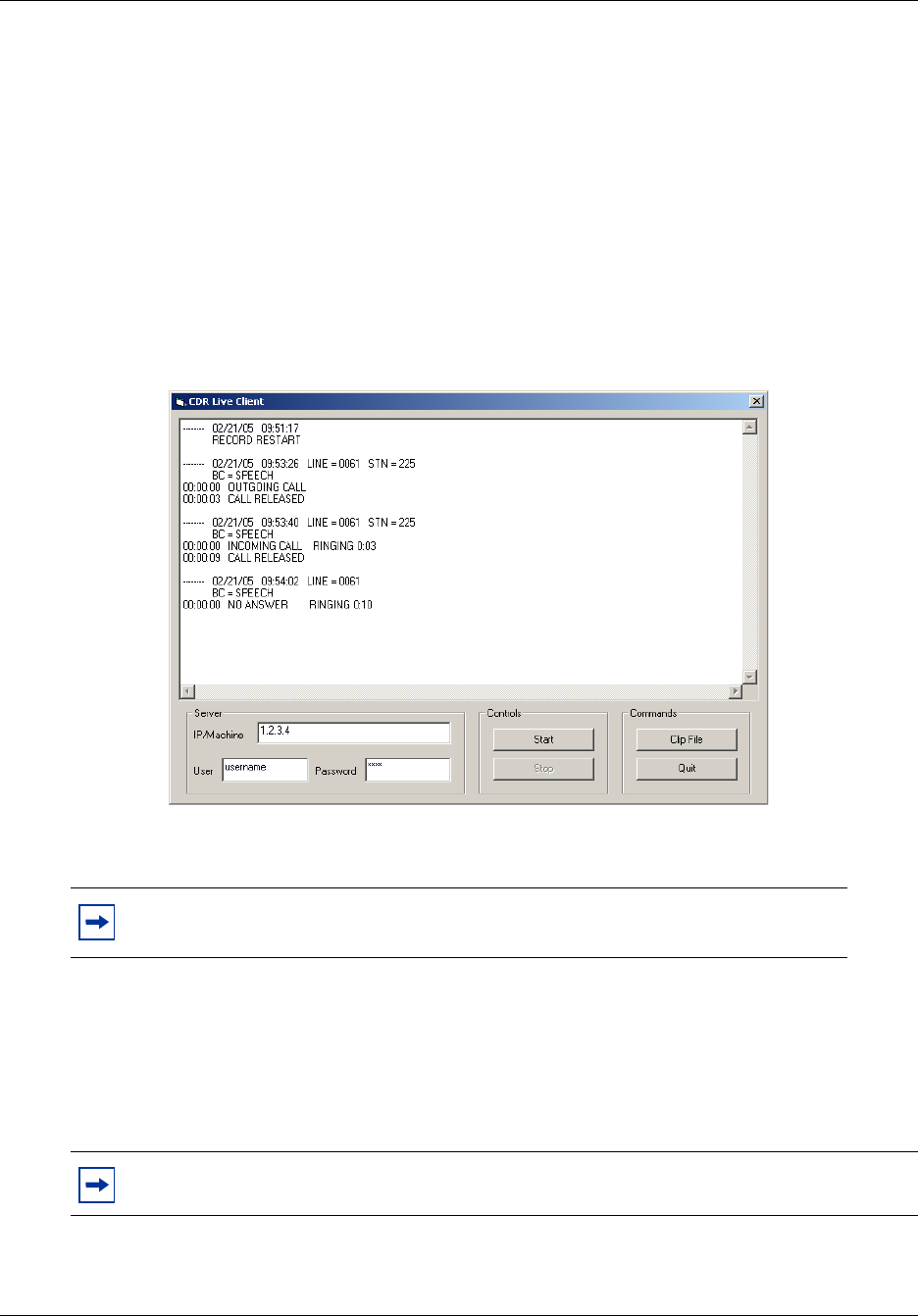
Call Detail Recording display
With the CDR Livestream you can monitor records remotely as calls occur.
To access the CDR Livestream
1Click the Start button and click Programs.
2Click Nortel and click CDR Livestream.
The CDR Livestream window appears. The CDR Livestream window displays real-time
statistics that you can view and print.
Figure 2 CDR Livestream window
To use the CDR Livestream
1Type the server name of the BCM 4.0 you want to connect to.
2Type the username and password to authenticate the user.
Must be part of CDR User Group on BCM.
3Click the Start button to view call activity records.
4Click Stop to stop viewing call activity records.
Note: You must have a Call Detail Recording user account on the BCM to use the
CDR Livestream.
Note: If you do not know the server name, ask your System Administrator.

40 Chapter 3 Configuring and managing CDR data
N0060599N0060599
To print records as you view them
1Select the record you want to print or right-click on the mouse to Select All.
2Right-click on the mouse to copy the record to the clipboard.
3Paste the record into a text application such as Word Pad or Notepad.
4Print the record.
Note: The CDR Livestream maintains a limited number of records. New records replace
old records after the buffer is full. All records are maintained on the BCM system. Use the
CDR data file transfer to obtain records and print files.

41
Call Detail Recording System Administration Guide
Chapter 4
Call Detail Recording reports
Call Detail Recording (CDR) provides two types of reports:
•“SL-1 reports”
•“Norstar reports”
SL-1 reports
Use the SL-1 report when the you are supplying the output to legacy commercial accounting
packages or equipment. SL-1 reports are in the form of one or two lines in ASCII characters.
This section describes the SL-1 reports and explains how to interpret them.
SL-1 report types
The CDR supports two different SL-1 report types:
•“SL-1 Standard reports”
•“SL-1 CLID reports”
The SL-1 Calling Line Identification (CLID) format is similar to the SL-1 Standard format with
the addition of CLID information. For lines that do not support CLID, or when the BCM server
does not deliver CLID information, calls report in an SL-1 Standard format.
SL-1 report field definitions
Table 6 and Table 7 show summaries of field definitions for SL-1 reports, line 1 and line 2.
Table 6 Field definitions for line 1
Column Name Format Definition
1 RecType Y report type
2 Blank N/A Blank space
3-5 RecNo XXX report sequence number
6 Blank N/A Blank space
7-8 CustNo 00 Customer number
9 Blank N/A Blank space
10-16 OrigID TXXXXXX
DNXXX
CF00001
Line number
STN number
Conference number
17 Blank N/A Blank space
42 Chapter 4 Call Detail Recording reports
N0060599N0060599
SL-1 report options
Call Detail Recording generates the SL-1 report options using letter codes, as shown in Table 8.
18-24 TerID TXXXXXX
DNXXXX
Line number
STN number
25-37 Blank N/A Blank space
38-48 TimeStamp MM/DD HH:MM Time stamp
49 Blank N/A Blank space
50-57 Duration HH:MM:SS Call duration
58 Blank N/A Blank space
59-90 Digits XXX...X Dialed digits
50-61 AccCode XXX...X Account code (C report)
Table 7 Field definitions for line 2
Column Name Format Definition
3-18 CLID XXX...X CLID number
11-15 AOCE XXXXXX.XX Call charges
11-15 Pulse Charge nnnnn
(00000-32767)
Pulse charge for the call. Valid only for ETSI ISDN
lines which support AOCE.
17-22 Currency
Charge
nnnnn
(000000-999999)
Currency charge for the call. Valid only for DASS2 and
ETSI ISDN lines that support AOCE.
Table 8 SL-1 report options and letter codes
Letter code Report option Notes
I Initialization report Contains only the report type and time stamp
N Normal report
S Start report Does not contain the duration field
E End report Does not contain the duration field
A Authorization report Does not contain any dialed digits
C Charge report Does not contain the duration field
M Conference Charge report Does not contain the duration field
XTransfer
Note: The I report does not contain the Call Information number; all other report types
contain the Call Information number (if delivered).
Table 6 Field definitions for line 1
Column Name Format Definition
Chapter 4 Call Detail Recording reports 43
Call Detail Recording System Administration Guide
SL-1 Standard reports
The following figures show examples of SL-1 Standard reports.
Figure 3 Outgoing call on line 52 from station set 7425
Figure 4 Incoming call on line 47 to station set 2221
Figure 5 Call transfer
An outgoing call on line 38 from station set 7447 and transferred to station set 2221.
Figure 6 Conference call
A two-line conference call with two outgoing calls.
Ad Hoc Multiparty Conferencing feature
In SL-1 format, the Ad hoc multiparty conferencing feature tracks a multiparty conference as a
Start (S), Transfer (X), End (E) record sequence, where the destination of the transfer is the
conference server for external parties only. The End record indicates the conference server as the
originating identifier.
A set of SL-1 records involving at least four parties in a conference displays any external party
involved in the conference call, regardless of the number of internal parties. All conference call
participants (both internal and external) produce a Start (S), Transfer (X) and End (E) record.
SL-1 CLID reports
The SL-1 CLID report has two lines. The CLID information, if available, appears in the third
character position of the second line.
The CLID number is always 16 digits. Any missing numbers are represented by an “x.” If there is
no CLID Information available, no CLID Information report is delivered.
N 027 00 DN7425 T052000 04/04 14:03 00:01:32 5551212
N 028 00 T047000 DN2221 04/04 14:22 00:12:04
S 029 00 DN7447 T038000 04/04 15:02 8761344
X 030 00 T038000 DN2221 04/04 15:03
E 031 00 T038000 DN2221 04/04 15:07
S 000 01 DN6545 T038000 04/04 12:23 9369552
E 001 01 CF0001 T038000 04/04 12:27
S 002 01 DN6789 T047000 04/04 12:23 8082635
E 003 01 CF0001 T047000 04/04 12:27
44 Chapter 4 Call Detail Recording reports
N0060599N0060599
Figure 7 Incoming call with CLID
An incoming call on line 38 to station set 2221 with CLID enabled. The CLID number available is
4037692000.
Figure 8 Incoming call with Call Information and no CLID
An incoming call on line 37 to station set 2211 with Call Information enabled. The CLID number
is not available.
Figure 9 Incoming call transferred with CLID
An incoming call on line 38 to station set 7447 and transferred to station set 2223. Call
Information is enabled, and the CLID is 4032919001.
SL-1 Target line/Physical lines
When target lines are used on digital trunks, reports show both the target line number and the
physical line number.
Figure 10 Target line transfer
An incoming call on target line 103 and transferred to another station set. The physical line is 37.
Auto Attendant and Call Center station set numbers
If the Auto Attendant answers incoming calls, the station set number reports with the DN of the
Auto Attendant. If Call Center answers incoming calls, the station set number reports with the
Control DN (CDN) of the Skillset that answers the call.
Advice of charges at end of call (AOCE)
On Integrated Services Digital Network (ISDN) ETSI lines only, the cost of a call is available on
an SL -1 record. Cost appears in dollars or pulse units. The maximum amount chargeable to an
SL-1 account is $999999 or 99999 units.
N 034 00 T038000 DN2221 04/04 15:32 00:10:24
4037692000xxxxxx
N 035 00 T037000 DN2211 04/04 14:22 00:12:04
S 029 00 T038000 DN7447 04/04 15:02
4032919001xxxxxx
E 030 00 T038000 DN2223 04/04 15:07
4032919001xxxxxx
S 029 00 T037103 DN7499 04/04 15:02
E 030 00 T037103 DN7370 04/04 15:07
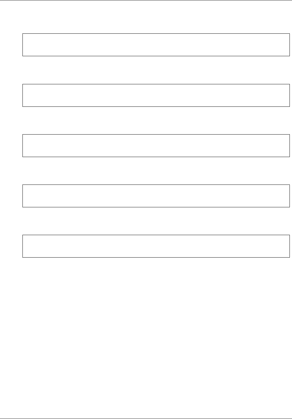
Chapter 4 Call Detail Recording reports 45
Call Detail Recording System Administration Guide
Figure 11 End of call with charges rounded down
End of call with currency charges of $123.45. The amount is rounded down to the nearest dollar.
Figure 12 End of call with charges rounded up
End of call with currency charges of $123.50. The amount is rounded up to the nearest dollar.
Figure 13 End of call with pulse charges
End of call with pulse charges of 456 units.
Figure 14 End of call with no charge
End of call with zero charges.
Figure 15 Sample end of call with charges not available
End of call with charges not available.
Norstar reports
Use Norstar reports when the you assign the CDR output to a call accounting package that
supports the Norstar report format.
Norstar report types
CDR supports four Norstar report types:
•“Norstar Standard reports”
•“Norstar CLID reports”
•“Norstar Real-time report”
•“Norstar All report”
N 003 00 DN0285 T181000 07/19 16:43 00:00:02 999
00000 000123
N 002 00 DN0285 T181000 07/19 17:21 00:00:03 888
00000 000124
N 012 00 DN0285 T181000 07/19 17:31 00:00:02 99
00456 000000
N 013 00 DN0285 T181000 07/19 17:33 00:00:04 45678
00000 000000
N 001 00 DN0285 T181000 07/19 17:43 00:00:02 888
46 Chapter 4 Call Detail Recording reports
N0060599N0060599
Norstar Standard reports
Norstar Standard reports start with a header line that contains the date (MM/DD/YY), time (HH/
MM/SS), and LINE and STN fields. The reports have at least one event line showing an event and
time stamp.
Figure 16 Outgoing call
An outgoing call in Standard format
Figure 17 Incoming call
An incoming call in Standard format.
Norstar CLID reports
With this option, CLID information received from the BCM 4.0 server for an incoming call
appears between the report header and the event lines. There is one occurrence of CLID
information per call. CLID information does not appear in the report if CLID information is not
available.
Norstar report field definitions
Calling number
The first line after the header line is the calling number, which can have a maximum of 11
characters. If the calling number information is incomplete, one of the following messages
appears:
• If the number is truncated, a forward slash (/) precedes the digits received.
• If a partial CLID number is received, ‘x’ follows the digits received.
• If the number field does not receive data, UNKNOWN appears.
Name
The second line is the name, which can have a maximum of 15 characters. If the name field does
not receive data, UNKNOWN appears.
Note: CDR reports CLID information only for lines that are capable of delivering CLID.
Your BCM 4.0 must have delivery of CLID information enabled.
-------- 04/04/99 11:39:43 LINE = 0003 STN = 7425
00:00:00 OUTGOING CALL
DIGITS DIALED 5551212
00:00:37 ACCOUNT CODE 87
00:12:59 CALL RELEASED
-------- 04/04/99 12:00:01 LINE = 0083 STN = 7726
00:00:00 INCOMING CALL RINGING 0:32
00:00:39 HOLD
00:01:12 UNHOLD
00:02:47 CALL RELEASED
Chapter 4 Call Detail Recording reports 47
Call Detail Recording System Administration Guide
Call type
The third line is the call type. This line appears if the call is a long-distance call. If the call type
field does not receive data, UNKNOWN appears.
Figure 18 Incoming call with CLID
Figure 19 Call with CLID not answered
An abandoned (not answered) incoming call with CLID.
Figure 20 Call with truncated CLID
Figure 21 Call with partial CLID
Norstar Real-time report
Real-time call records are one line long. All real-time records begin with an asterisk (*) to
differentiate them from non-real-time call records. Real-time records are generated only when
CLID Information is available. You can also generate real-time records for five call states and four
hospitality types.
-------- 04/04/99 11:12:01 LINE = 0013 STN = 7465
CALLING NUMBER 4032919123
NAME UNKNOWN
UNKNOWN
BC = SPEECH
00:00:00 INCOMING CALL RINGING 0:32
00:00:39 HOLD
00:01:12 UNHOLD
00:02:47 CALL RELEASED
-------- 04/04/99 20:30:00 LINE = 0035
CALLING NUMBER 4032919123
NAME UNKNOWN
UNKNOWN
BC = SPEECH
00:00:00 NO ANSWER RINGING 3:15
-------- 04/04/99 11:12:01 LINE = 0013 STN = 7465
CALLING NUMBER /12345678901
NAME UNKNOWN
UNKNOWN
BC = SPEECH
00:00:00 INCOMING CALL RINGING 0:32
00:00:39 HOLD
00:01:12 UNHOLD
00:02:47 CALL RELEASED
-------- 04/04/99 11:12:01 LINE = 0013 STN = 7465
CALLING NUMBER 1234567890x
NAME UNKNOWN
UNKNOWN
BC = SPEECH
00:00:00 INCOMING CALL RINGING 0:32
00:00:39 HOLD
00:01:12 UNHOLD
00:02:47 CALL RELEASED
48 Chapter 4 Call Detail Recording reports
N0060599N0060599
You can use the record information to drive external PC database applications; for example, to
compile customer information by extracting the CLID data from the real-time records.
Figure 22 Call with DNIS
A call, ringing with DNIS, answered and released
Figure 23 Transferred call
Table 9 Norstar real-time report options and letter codes
Letter code Report option Description
G Ringing Ringing is unique to real-time records, and
indicates a line that is ringing when CDR
receives the CLID Information.
D Dialed Number Identification Service
(DNIS)
Reported only if the line delivers the DNIS
information. If present, it appears after
Ringing information.
AAnswered
NNo Answer
T Transferred
R Released
HV Hospitality vacant
HB Hospitality basic
HM Hospitality mid
*030198 154615 0019 6137635114 John Doe U G
*030198 154615 0019 6137635114 4037352000 U D
*030198 154623 0019 7832 6137635114 John Doe U A
*030198 154831 0019 7832 6137635114 John Doe U R
*041197 094105 0003 7692000 Alan Smith U G
*041197 094105 0003 7692000 7305432 U D
*041197 094111 0003 7344 7692000 Alan Smith U A
*041197 094156 0003 7440 7692000 Alan Smith U T
*041197 094414 0003 7440 7692000 Alan Smith U R

Chapter 4 Call Detail Recording reports 49
Call Detail Recording System Administration Guide
Norstar All report
This report contains Standard, CLID Information and real-time records.
Figure 24 Sample call with Standard, CLID and Real-time information
The figure shows a call record when All is selected. The RINGING record shows the call-received
time with CLID Information, not the start alert-time. The call was answered 15 seconds after the
ringing began. The call was transferred 25 seconds after it was answered and was released two
minutes after it was transferred.
Auto Attendant and Call Center station set numbers
If the Auto Attendant answers incoming calls, the station set number appears as the DN of the
Auto Attendant. If Call Center answers incoming calls, the station set number appears as the
Control DN (CDN) of the Skillset that answered the call.
Standard Hospitality record format
The Hospitality record shows four states of room occupancy: vacant, basic, mid, and full. Room
number lengths can be from one to five digits.
Figure 25 Room status vacant
A Standard Hospitality record with room 12345 status set as vacant.
*030298 154920 0022 4037692000 UNKNOWN D G
*030298 154920 0022 4037692000 8002349876 D D
*030298 154935 0022 7101 4037692000 UNKNOWN D A
*030298 155000 0022 7169 4037692000 UNKNOWN D T
*030298 155200 0022 7169 4037692000 UNKNOWN D R
-------- 03/02/98 15:49:20 LINE = 0022 STN = 7101
CALLING NUMBER 4037692000
NAME UNKNOWN
LONG DISTANCE
DNIS NUMBER 8002349876
BC = SPEECH
00:00:00 INCOMING CALL RINGING 0:15
00:00:20 HOLD
00:00:25 TRANSFERRED
-------- 03/02/98 15:50:00 LINE = 0022 STN = 7169
00:00:00 FROM TRANSFER
00:00:00 UNHOLD
00:02:00 CALL RELEASED
-------- 23/01/98 23:49:00 STN = 12345
HOSPITALITY VACANT
50 Chapter 4 Call Detail Recording reports
N0060599N0060599
Figure 26 Room status basic
A Standard Hospitality record with room 732 status set as basic
Figure 27 Room status mid
A Standard Hospitality record with room 73 status set to mid
Figure 28 Room status full
A Standard Hospitality record with room 7 status set to full
Target line/physical lines
If you use target lines on digital trunks, the Call Detail Recording reports show both the target line
and the physical line number.
Figure 29 Target line and physical line
An incoming call on a target line. The target line number is 101 and the physical line number is 38.
Station 7468 answers the call.
Busy reports
CDR produces two types of busy reports:
• Direct Inward Dial
• Target Line
Direct Inward Dial busy
A call rings busy when the digital line is set up as a Direct Inward Dial (DID) line that requires
receive digits to route the call through the BCM 4.0 server via a target line. If all target line
destinations are busy, the unit returns a busy signal instead of routing the call to the prime station
set. CDR produces a busy report.
-------- 23/01/98 23:49:00 STN = 732
HOSPITALITY BASIC
-------- 23/01/98 23:49:00 STN = 73
HOSPITALITY MID
-------- 23/01/98 23:49:00 STN = 7
HOSPITALITY FULL
-------- 12/12/97 12:00:01 LINE = 0101 STN = 7468
00:00:00 INCOMING CALL
LINE = 0038
00:28:33 CALL RELEASED
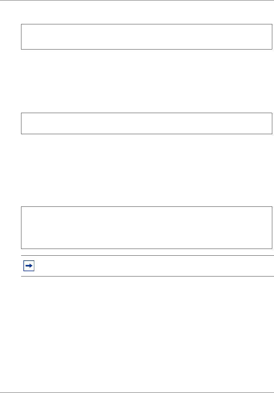
Chapter 4 Call Detail Recording reports 51
Call Detail Recording System Administration Guide
Figure 30 Busy call with DID
Target line busy
A call rings busy when a target line is involved with a call, and a second incoming call tries to use
the same line. CDR produces a busy report, but does not include the target line information. Figure
31 shows an example of a call to a busy target line.
Figure 31 Call to a busy target line
CDR reports busy only if the BCM 4.0 server is programmed to provide busy treatment.
Bearer Capability data
When you assign Call Detail Recording to report in the Norstar CLID report format, Call Detail
Recording provides Bearer Capability information associated with the call.
Figure 32 Incoming call with Bearer Capability
PRI call-by-call service
If the ISDN Primary Rate Interface (PRI) trunk is installed in the BCM 4.0 server, Call Detail
Recording provides PRI call-by-call service information as part of the CLID call records in
Norstar CLID format. The record provides both the service type and service ID for incoming and
outgoing calls.
Note: This information appears in the Norstar report if your BCM 4.0 server supports
Bearer capabilities.
-------- 03/02/99 15:09:32 LINE = 0235
00:00:00 BUSY
LINE = 0035
-------- 03/02/99 14:36:02 LINE = 0035
00:00:00 BUSY
-------- 12/03/99 14:36:00 LINE = 0035
CALLING NUMBER 7355303
NAME UNKNOWN
UNKNOWN
BC = SPEECH
00:00:00 NO ANSWER RINGING 0:02
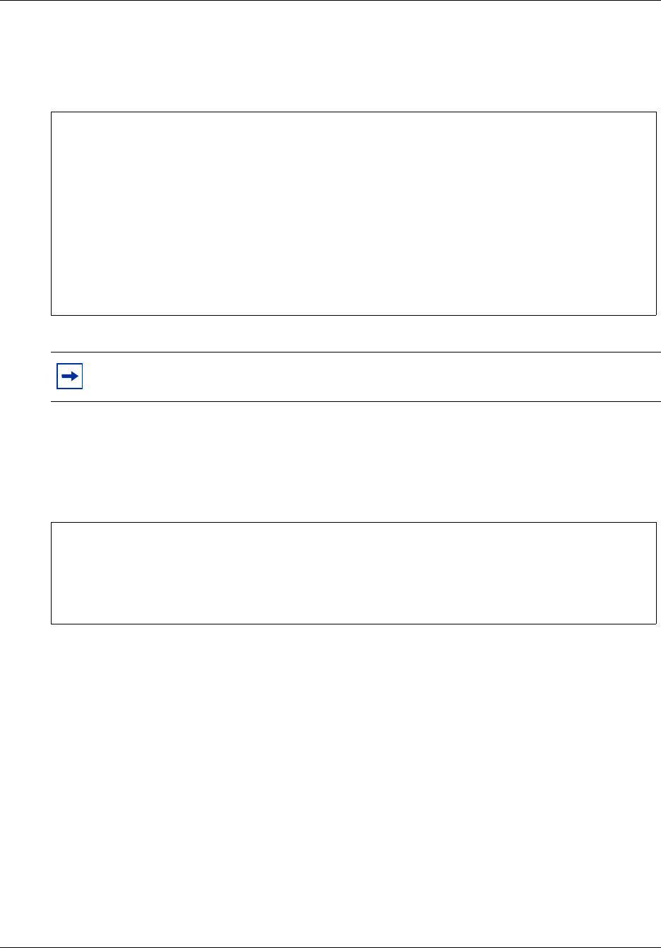
52 Chapter 4 Call Detail Recording reports
N0060599N0060599
Figure 33 PRI
An incoming call using the TIE service with service ID 0 and the corresponding outgoing call
using the PUBLIC service
Voice over IP calls
Calls, both incoming and outgoing, that use Voice over IP (VoIP) appear in the CLID report.
Figure 34 Incoming call with VoIP
Dialed number identification service
Certain trunk types support the delivery of Dialed Number Identification Service (DNIS). CDR
supports the reporting of DNIS as part of the CLID call reports. Both the Norstar CLID and
Norstar Real-time format support DNIS reporting.
Note: BCM 4.0 supports PRI only with the necessary hardware installation and the PRI
trunks configuration to deliver PRI call-by-call service information.
-------- 01/01/98 01:38:00 LINE = 0001 STN = 221
CALLING NUMBER 6135551212
NAME UNKNOWN
UNKNOWN
DNIS NUMBER 9772210
BC = SPEECH
PRI SERVICE TIE 0
00:00:00 INCOMING CALL RINGING 0:00
00:01:35 CALL RELEASED
-------- 01/01/98 01:38:00 LINE = 0023 STN = 223
BC = SPEECH
PRI SERVICE PUBLIC
00:00:00 OUTGOING CALL
DIGITS DIALED 9772210
00:01:35 CALL RELEASED
-------- 12/03/99 14:36:00 LINE = 0035
CALLING NUMBER 7355303
NAME UNKNOWN
UNKNOWN
BC = SPEECH
VOIP CALL
00:00:00 NO ANSWER RINGING 0:02
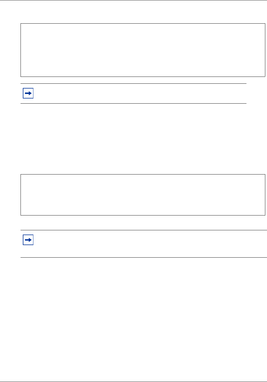
Chapter 4 Call Detail Recording reports 53
Call Detail Recording System Administration Guide
Figure 35 Incoming call with DNIS
Call connected digit separator
CDR usually reports all the digits that a user dials to connect a call. The digits can include digits
responding to prompts from the Automated Attendants, extension transfer, or voice mail service.
To identify the digits dialed to connect the call, and the digits dialed after the call is connected, you
can insert an exclamation mark (!) between them.
Figure 36 Outgoing call with digit separator
External call forwarding
External call forwarding occurs if an extension is configured to externally forward calls in these
situations:
• Call Forward All Calls (CFAC)
• Call Forward Busy (CFB)
• Call Forward No Answer (CFNA)
If an incoming call is unanswered and externally forwarded, CDR reports the call as outgoing. The
reports show:
• incoming line or extension
• outgoing line
Note: BCM 4.0 support DNIS only with the necessary hardware installation and
trunk configuration to deliver DNIS information.
Note: Call Detail Recording cannot differentiate between the digits required to connect a
call and extra digits dialed before the call is connected. Not all units support the delivery
of call-connected signals so this feature is not available on all BCM 4.0 servers.
-------- 01/01/99 01:38:00 LINE = 0001 STN = 221
CALLING NUMBER 6135551212
NAME UNKNOWN
UNKNOWN
DNIS NUMBER 9772210
BC = SPEECH
PRI SERVICE TIE 0
00:00:00 INCOMING CALL RINGING 0:00
00:01:35 CALL RELEASED
-------- 01/01/99 01:38:00 LINE = 0023 STN = 223
BC = SPEECH
00:00:00 OUTGOING CALL
DIGITS DIALED 9772210!0132
00:01:35 CALL RELEASED
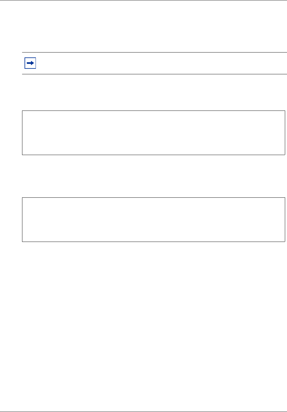
54 Chapter 4 Call Detail Recording reports
N0060599N0060599
• extension responsible for the external call forward
• reason for the external call forward
• digits dialed
Figure 37 Sample external call with external call forward
An incoming call on line 0001 that was externally forwarded to line 0002. Extension 221 is
responsible for the external call forward event.
Figure 38 Sample internal call with external call forward
An internal call that was externally forwarded to line 0002. Extension 222 originated the call.
Extension 221 is responsible for the external call forward event.
Ad hoc multiparty conference calls
The Ad hoc multiparty conferencing feature allows CDR to track multiparty conference calls and
provide information on when parties have joined or left the conference. You can use this data for
call accounting purposes and for statistical tracking of conference resources.
With the introduction of Ad hoc multiparty conferencing feature, a station involved in a
three-party conference can add more participants using Feature 3. When a fourth participant is
added, all conferenced parties are transferred to a new conference serve, and a bridge is created.
When the bridge is created, a conference server record is also created. In Norstar reports, the start
and end times of all participants, both internal and external, are recorded.
Note: For more information, refer to the Installation and Maintenance Guide for your
system.
-------- 12/31/99 11:59:59 LINE = 0001 LINE = 0002
CALLING NUMBER 4032919123
BC = SPEECH
EXT CALL FWD STN = 221 REASON = CFAC
00:00:00 OUTGOING CALL
DIGITS DIALED 5551212
00:02:47 CALL RELEASED
-------- 12/31/99 11:59:59 STN = 222 LINE = 0002
CALLING NUMBER 4032919123
BC = SPEECH
EXT CALL FWD STN = 221 REASON = CFAC
00:00:00 OUTGOING CALL
DIGITS DIALED 5551212
00:02:47 CALL RELEASED

Chapter 4 Call Detail Recording reports 55
Call Detail Recording System Administration Guide
Norstar report field definitions
Figure 39 Standard and CLID report formats
This figure shows all of the lines available for printing by CDR in the Norstar report
0 1 2 3 4 5 6 7
1234567890123456789012345678901234567890123456789012345678901234567890
-------- MM/DD/YY HH:MM:SS LINE = XXXX STN = XXXXXXX
-------- MM/DD/YY HH:MM:SS LINE = XXXX LINE = XXXX
-------- MM/DD/YY HH:MM:SS LINE = XXXX
-------- MM/DD/DY HH:MM:SS
RECORD RESTART
00:00:00 INCOMING CALL RINGING 0:00
00:00:00 OUTGOING CALL
00:00:00 NO ANSWER RINGING 0:00
00:00:00 FROM TRANSFER
00:00:00 INVALID PASSWORD
00:00:00 HOLD
00:00:00 UNHOLD
00:00:00 ACCOUNT CODE 123
00:00:00 BUSY
DIGITS DIALED 9369552
00:00:00 CONFERENCE STN2 = 7425
00:00:00 CONFERENCE LINE2 = 0052
00:00:00 CONFERENCE END
00:00:00 RESTRICTI0N PASSWORD 99
00:00:00 CALL CHARGES = PULSES
00:00:00 CALL RELEASED
00:00:00 TRANSFERRED
00:00:00 FROM TRANSFER
RECORDS LOST
LINE = 0015
BC = SPEECH
BC = UNRESTRICTED DIGITAL
BC = RESTRICTED DIGITAL
BC = 3.1 kHZ AUDIO
BC = 7 kHZ AUDIO
BC = VIDEO
CALLING NUMBER 4032919123
CALLING NUMBER /12345678901
CALLING NUMBER 4032919123x
NAME Peter Pan
LONG DISTANCE
UNKNOWN
DNIS NUMBER 4032652300
PRI SERVICE PUBLIC
PRI SERVICE PRIVATE
PRI SERVICE TIE
PRI SERVICE FX
PRI SERVICE OUTWATS
PRI SERVICE SWITCHED DIGITAL
PRI SERVICE INWATS
PRI SERVICE INTL INWATS
PRI SERVICE 900
HOSPITALITY VACANT
HOSPITALITY BASIC
HOSPITALITY MID
HOSPITALITY FULL
EXT CALL FWD STN = 4221 REASON = CFAC
EXT CALL FWD STN = 4222 REASON = CFB
EXT CALL FWD STN = 4227 REASON = CFNA
VOIP CALL

56 Chapter 4 Call Detail Recording reports
N0060599N0060599
Figure 40 Real-time record format
This figure shows the lines available for printing by CDR in the real-time report
Norstar Standard and CLID report description
For non-Real-time Standard and CLID reports, each line has a maximum of three fields (except for
the header line).
The header line has a maximum of five fields:
Line descriptions
The Norstar standard and CLID reports can have three, four, or five fields. The date and time
reflect the date and time the call started. For incoming calls, the start time is when the call is
answered. For outgoing calls it is the time the line is seized. The LINE field is fixed at four digits.
The STN directory number (DN) ranges from two to seven digits in length. For outgoing tandem
calls, both the fourth and the fifth fields are LINE.
Field Contents
1 8 dashes
2 date the call originated
3 time the call originated
4 line used
5 line, or station using line from 4th field
0 1 2 3 4 5 6 7
1234567890123456789012345678901234567890123456789012345678901234567890
*MMDDYY HHMMSS LINE STATION CLID NUMBER NAME/DNIS TYPE EVENT
*030193 154615 0019 6137635122 Alan Smith U G
*030193 154615 0019 6137635122 4032632300 U D
*030193 154615 0019 7343 6137635122 Alan Smith U A
*030193 154615 0019 7343 6137635114 Alan Smith U N
*030193 154615 0019 7343 6137635122 Alan Smith U T
*030193 154615 0019 7343 6137635114 Alan Smith U R
*012398 234900 12345 H V
*012398 234900 12345 H B
*012398 234900 12345 H M
*012398 234900 12345 H F
Chapter 4 Call Detail Recording reports 57
Call Detail Recording System Administration Guide
Figure 41 Start header line
The header line indicates the start of a call report, or the continuation of a call report after a
transfer.
Figure 42 Restart line
The restart line follows the header line when CDR or the BCM 4.0 server restarts
Figure 43 Call ringing line
The line following the header line (with all five fields), or after the CLID Information. The time in
the header line shows when the call was answered. This time minus the ringing duration (the third
field) shows when the call started ringing.
Call Detail Recording reports calls based on events (change of call states):
• First field: time the associated event occurred. The time is an offset from the start time of the
call indicated in the header.
• Second field: describes the event associated with the call. Events can be either a call state, such
as hold or transfer, or a user action, such as account code entry.
• Third field: data that describes the action in the second field.
Figure 44 Outgoing line
The line following the header line (with all five fields). The time in the header line field shows
when the call was initiated.
Figure 45 Sample unanswered call line
The line following the header line if an incoming call is unanswered.
Figure 46 Sample busy line
The line that appears if an incoming call receives busy treatment
-------- MM/DD/YY HH:MM:SS LINE = XXXX STN = XXXXXX
RECORD RESTART
00:00:00 INCOMING CALL RINGING 0:04
00:00:00 OUTGOING CALL
00:00:00 NO ANSWER RINGING 0:22
00:00:00 BUSY
58 Chapter 4 Call Detail Recording reports
N0060599N0060599
Figure 47 Hold and off-hold lines
The line that appears if a call is put on hold or taken off hold
Figure 48 Conference start and end lines
The line that shows the start and the end of a conference. The third party in the conference can be
a second station set or a second line as indicated in the third field.
Figure 49 Call transfer line
The line that appears if a call is transferred
Figure 50 Call transfer from line
The line that appears if a call was transferred. It indicates the start of the call at the new station set
that received the transfer.
Figure 51 End call line
The line that shows the last state of a call. It is followed by a carriage return and two line feeds so
that there is a blank line before the start of the next call report.
Figure 52 Digits dialed line
The line that shows the digits dialed. This line appears in outgoing call reports. A maximum of 32
digits or characters can appear. If the call connected digit separator option is enabled, an
exclamation mark (!) appears between digits dialed before and after the call connects.
Figure 53 Invalid password line
The line that appears if a user or caller enters an invalid password
00:00:04 HOLD
00:00:06 UNHOLD
00:10:32 CONFERENCE STN2 = 7425
00:12:12 CONFERENCE LINE2 = 0052
00:12:45 CONFERENCE END
00:00:00 TRANSFERRED
00:00:00 FROM TRANSFER
00:00:00 CALL RELEASED
DIGITS DIALED XXXXXXXXXXXXXXXXXXXXXXXXXXXXXXXX
DIGITS DIALED 123456789!1234
00:00:00 INVALID PASSWORD
Chapter 4 Call Detail Recording reports 59
Call Detail Recording System Administration Guide
Figure 54 Account code line
The line that appears if an account code is entered. Account codes can be a maximum of 12 digits.
Figure 55 Password
The line that appears if a password is entered. The password ID is a maximum of two digits
(00-99). The report indicates the password override ID and not the password itself.
Figure 56 Last line
The line that shows the last line of a call report if call states are missed, or if a call is missed
altogether. This line is followed by a carriage return and two line feeds so that there is a blank line
before the start of the next call report.
Figure 57 Physical line
The line that identifies the physical line of an incoming call on a target line. The line number is
fixed at four digits (with leading zeroes).
Figure 58 CLID information
The lines that appear if CLID information is available. The calling number can be a maximum of
12 characters, of which a maximum of 11can be digits. If a number received is longer than 11
digits, then slash (/) is the first character, followed by the 11 least significant digits. The name can
be a maximum of 15 characters. Each of the number and name can contain UNKNOWN. The third
line is the call type, which indicates either LONG DISTANCE or UNKNOWN if call type
information is not available. The DNIS number, if available, appears after the call type. The DNIS
number is followed by the Bearer Capability. The last line is the PRI call-by-call service, which
appears only when the PRI service information is available.
Figure 59 Room status
The lines that appear if the room occupancy status of a room changes to vacant.
00:00:00 ACCOUNT CODE XXXXXXXXXXXX
00:00:00 RESTRICTION PASSWORD XX
REPORTS LOST
LINE = XXXX
CALLING NUMBER XXXXXXXXXXX
NAME XXXXXXXXXXXXXXX
UNKNOWN
DNIS NUMBER XXXXXXXXXX
BC = SPEECH
PRI SERVICE TIE XXXXX
VOIP CALL
-------- 23/01/98 23:49:00 STN = 12345
HOSPITALITY VACANT
60 Chapter 4 Call Detail Recording reports
N0060599N0060599
Figure 60 Sample external call forward
The line that appears if a call is externally forwarded. This line shows the extension that is
responsible for the external call forward.
Norstar Real-time record description
Table 10 Real-time record
The Real-time record is one line long, beginning with an asterisk (*) to differentiate it from other
Norstar records. This record contains eight fields.:
Real-time Hospitality record format
The Ragtime Hospitality record shows four states of room occupancy:
• vacant
•basic
Field Description
Date In MMDDYY format
The month, day or year are preceded by a leading 0 to keep the field length
fixed. For example, 010501 is January 5, 2001.
Time In HHMMSS format
There are no separators between hour, minute, and second.
Line number Line number associated with call
Fixed at four digits and can have leading zeros. For example, 0019 is line
19. As the Real-time Hospitality record does not use the third field, it does
not contain any characters and appears blank.
Station set number Station set number associated with call
Station set numbers range from 2 - 7 digits. If the number is less than
seven digits there are no leading zeros because this field is not fixed. In the
Real-time Hospitality record this field shows the room number. Room
numbers range from 1 - 5 digits.
CLID number Shows the calling number
The number is a maximum of 12 characters (11 digits maximum and the (/)
and “x” characters). There is always information in this field. If no number is
available, either UNKNOWN or PRIVATE appears in this field. As the
Real-time Hospitality record does not use this field it appears blank.
CLID name or DNIS number Shows the name, which is a maximum of 15 characters. If no name is
available, UNKNOWN appears in this field. DNIS information in “D” records
replaces this field. The DNIS is a maximum of 10 digits. In the Real-time
Hospitality record this field shows the room occupancy status indicator.
Call type Shows either long distance (D) or unknown (U) status.
Call state Contains a call state indicator, followed by a carriage return and two line
feeds.
EXT CALL FWD STN = 221 REASON = CFAC
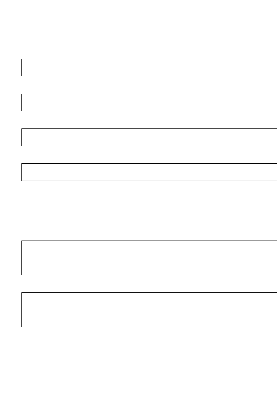
Chapter 4 Call Detail Recording reports 61
Call Detail Recording System Administration Guide
•mid
•full
Room number lengths range from one to five digits.
Figure 61 Room status vacant
Figure 62 Room status basic
Figure 63 Room status mid
Figure 64 Room status full
Advice of charges at end of call
On ISDN ETSI lines only, the cost of a call is available on a Norstar record. Cost appears in
dollars or pulse units.
Figure 65 Charges in dollars
Figure 66 Charges in lira
*012398 234900 12345 H V
*012398 234900 732 H B
*012398 234900 73 H M
*012398 234900 7 H F
-------- 07/19/00 16:13:11 LINE = 0181 LINE = 285
BC = SPEECH
00:00:00 OUTGOING CALL
DIGITS DIALED 54672
CALL CHARGE = 123.45 $
00:00:08 CALL RELEASED
-------- 07/19/00 16:16:56 LINE = 0181 LINE = 285
BC = SPEECH
00:00:00 OUTGOING CALL
DIGITS DIALED 98
CALL CHARGE = 123 Lira
00:00:03 CALL RELEASED
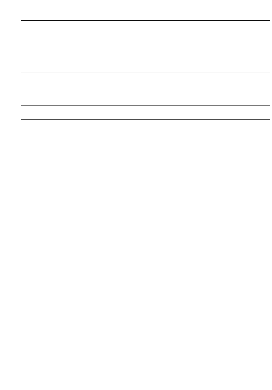
62 Chapter 4 Call Detail Recording reports
N0060599N0060599
Figure 67 Charges in units
Figure 68 No charge
Figure 69 Charges not available
-------- 07/19/00 16:28:15 LINE = 0181 LINE = 285
BC = SPEECH
00:00:00 OUTGOING CALL
DIGITS DIALED 546
CALL CHARGE = 456 PULSES
00:00:04 CALL RELEASED
-------- 07/19/00 16:29:40 LINE = 0181 LINE = 285
BC = SPEECH
00:00:00 OUTGOING CALL
DIGITS DIALED 55
CALL CHARGE = 0
00:00:03 CALL RELEASED
-------- 07/19/00 16:26:13 LINE = 0181 LINE = 285
BC = SPEECH
00:00:00 OUTGOING CALL
00:00:02 CALL RELEASED
00:00:02 CALL RELEASED

Index 63
Call Detail Recording System Administration Guide
Index
A
accessing
Call Detail Recording
livestream 38
account code list
descriptions 17
account codes
feature code 17
Ad Hoc Multiparty Conferencing Feature 43
administration
User Group administration 21
AOCE, advice of charges at end of call
SL-1 reports 44
applications
Call Detail Recording 11
livestream 38
assigning
date format 14
header format 14
prefix filters 18
report filters 15
report language 15
assigning report formats
Norstar 13
SL-1 13
auto attendant
set numbers 49
Auto Attendant, station set numbers 49
automated attendants 53
B
busy
Norstar Direct Inward Dial 50
Norstar reports 50
Norstar Target line
busy 51
Busy reports
Direct Inward Dial 50
Target Line 50
C
call center
set numbers 49
Call Center station set numbers 49
call connected digit separator 53
Call Detail Recording 18, 45
Ad Hoc Multiparty Conferencing Feature 43
AOCE
advice of charges at end of call 44
assigning
prefix filters 18
assigning report filters 15
Auto Attendant
station set numbers 44
call record security 7
client 38
configuring 11
prefix filters 17
Report Options 11
configuring data 21
configuring leading digits suppression
assigning Suppress Digits 20
changing Suppress Digits 20
configuring report contents
Element Manger 18
Contact Center
station set numbers 44
data files 11
date format
assigning 14
designating feature codes 16
feature codes 16
account code 17
account code list 17
features
Ad Hoc Multiparty Conferencing 43
header format 14
livestream
accessing 38
managing data 21
Norstar
assigning a report format 13
Norstar CLID reports
field definitions 46
Norstar report types
all reports 45
CLID reports 45
real-time reports 45
standard reports 45
Norstar reports
CLID 46
standard reports 46

64 Index
N0060599N0060599
Norstar Standard reports
incoming call 46
outgoing call 46
parameters
programming 11
prefix filters
assigning 18
deleting 18
printing records 39
report contents 18, 19
configuring 18
descriptions 18
Display connection character 19
Include call charge info 19
Include CLID with call type 18
Include CLID with name 18
Include DNIS Info 18
Include long CLID 18
maximum digits after connection 19
options 18
Use answer supervision 19
report filters 15
feature code F9 16
filter type 16
hospitality records 16
minimum call duration 16
report format
SL-1 Standard 43
report formats
Norstar 13, 45
SL-1 13
report language 15
assigning 15
Report Options
configuring 11
report types
Norstar 41
Norstar real-time 47
reports 41
SL-1 41
Standard Norstar reports 46
security 21
call record 7
SL-1
assigning a report format 13
letter codes 42
report options 42
SL-1 CLID reports 43
incoming call transferred with CLID 44
incoming call with Call Information and no CLID
44
incoming call with CLID 44
SL-1 report format
advice of charges at end of call 44
call charges 44
SL-1 reports
CLID reports 43
field definitions 41, 42
SL-1 Standard reports
call transfer 43
conference call 43
incoming call 43
outgoing call 43
SL-1 target line/physical line
target line transfer 44
Suppress digits 19
after connect is enabled and Line Supervision is
available 19
after connect is enabled and Line Supervision is
not available 19
suppress digits
after connect is disabled 19
System Administrator
role 7
tasks 7
User Group administration 21
using
livestream 38
Call Detail recording
Auto Attendant
station set numbers 44
Contact Center
station set numbers 44
Call Detail Recording data
configuring 21
Call Detail Reording
report filter types
All 16
Outgoing 16
Prefix 16
report filters
descriptions 16
Call Forward ALl Calls 53
Call Forward Busy 53
Call Forward No Answer 53
call record
Call Detail Recording
security 7
call types
VoIP 52
call-by-call service 51
changing

Index 65
Call Detail Recording System Administration Guide
prefix filters
Call Detail Recording 18
CL-1
Call Detail Recording reports 41
CLID reports
Call Detail Recording
SL-1 43
line descriptions 56
conferencing
Ad Hoc Multiparty
Call Detail Recording 43
configuring
Call Detail Recording 11
prefix filters 17
Report Options 11
CDR report contents 18
prefix filters
Call Detail Recording 17
report contents
Call Detail Recording 18
configuring Report Options 11
D
deleting
prefix filters
Call Detail Recording 18
descriptions
Real-time record 60
dialed number 52
Dialed Number Identification Service 52
digit suppression
Call Detail Recording
after connect is disabled 19
after connect is enabled and Line Supervision is
available 19
after connect is enabled and Line Supervision is
not available 19
assigning Suppress Digits 20
changing Suppress Digits 20
configuring leading digits suppression 20
Direct Inward Dial 50
E
Element Manager
assigning
CDR prefix filters 18
Call Detail Recording 11
livestream 38
Call DetailRecodring
User Group Administration 21
changing
CDR prefix filters 18
deleting
CDR prefix filters 18
Suppress Digits
Call Detail Recording 20
end of call with charges not available 45
end of call with charges rounded down 45
end of call with charges rounded up 45
end of call with no charge 45
end of call with pulse charges 45
extension transfer 53
external call forward 60
external call forwarding
configurations
Call Forward All Calls 53
Call Forward All No Answer 53
Call Forward Busy 53
F
feature code types
Call Detail Recording
account code 17
feature codes
account code list
Call Detail Recording 17
Call Detail Recording 16
account code list 17
account codes 17
creating 16
designating 16
Field definitions
CLID report 46
field definitions
Norstar reports
CLID 55
real-time 56
standard 55
formats
date
Call Detail Recording 14
H
header format
Call Detail Recording 14
Hospitality record
Real Time 60
Standard 49

66 Index
N0060599N0060599
I
iIdentification service 52
Inward Dial
Busy Report 50
L
language
reports
Call Detail Recording 15
letter codes
Call Detail Recording
SL-1 report options 42
line descriptions
call ringing line 56
outgoing line 56
restart line 56
start header line 56
unanswered call line 56
lines
physical 50
target 50
livestream
Call Detail Recoding
accessing 38
Call Detail Recording
accessing 38
using 38
long distance
prefix filter
Call Detail Recording 17
M
managing
Call Detail Recording data 21
N
Norstar 41
Call Detail Recording reports 41
real-time reports
letter codes 48
options 48
Norstar CLID reports
field definitions
call type 47
calling number 46
name 46
Norstar field report definintions
calling number 46
calltype 46
name 46
Norstar report format
Call Detail Recording 13
report types 45
Norstar report formats
CLID
Bearer Capability 51
Norstar reports
Call Detail Recording
all reports 45
CLID reports 45, 46
real-time reports 45, 47
standard reports 45
CLID
field definitions 55
descriptions
CLID 56
standard 56
line descriptions
account code line 58
busy line 57
call ringing line 56
call transfer from line 58
call transfer line 58
CLID 56
CLID information 59
conference end line 57
conference start line 57
digits dialed line 58
end call line 58
external call forward 59
hold line 57
invalid password line 58
last line 58
off-hold line 57
outgoing line 56
password 58
physical line 58
restart line 56
room status 59
start header line 56
unanswered call line 56
standard
field definitions 55
line descriptions 56
Norstar Standard reports
Call Detail Recording
incoming call 46
outgoing call 46
Norstar Target line 51
Norstart reports

Index 67
Call Detail Recording System Administration Guide
Call Detail Recording
Standard 46
Nostar reports
CLID
DNIS 52
P
Physical lines
Norstar 50
physical lines 50
prefix filter
Call Detail Recording
long distance 17
prefix filters
Call Detail Recording
configuring 17
changing 18
Call Detail Recording 18
deleting
Call Detail Recording 18
Primary Rate Interface
call-by-call service 51
printing
CDR records 39
programming
Call Detail Recording parameters 11
PUBLIC service 52
R
Real-time record
fields
call state 60
call type 60
CLID number 60
date 60
line number 60
station set number 60
time 60
recodrs
Call Detail Recording
printing 39
record formats
Standard Hospitality 49
records
Real-time 60
report contents
Call Detail Recording
descriptions 19
report filters
Call Detail Recording
feature code F9 16
filter types 16
hospitality records 16
minimum call duration 16
Report format
Norstar Real Time 47
Norstar, call charges 61
SL-1 41
report formats
Call Detail Recording
Norstar 13
SL-1 13
SL-1 Standard 43
Report Options
Call Detail Recording 11
report type
SL-1 41
report types
Call Detail Recording
Norstar 45
SL-1 41
Norstar
all 49
reports
Bearer Capability 51
Busy 50
Call Detail Recording 41
assigning filters 15
Norstar 41
SL-1 41
SL-1 CLID 43
SL-1 report options 42
physical lines 50
SL-1 41
target line 50
RINGING record 49
S
security
Call Detail Recording 21
call record 7
service
TIE 52
services
call-by-call 52
PUBLIC 52
voice mail 53
set numbers
auto attendant 49

68 Index
N0060599N0060599
call center 49
SL-1
Call Detail Recording
standard report format 43
Calling Line Identification format 41
Standard format 41
SL-1 records
As Hoc Multiparty Conferencing 43
SL-1 report format
Call Detail Recording 13
SL-1 reports
Call Detail Recording
field definitions 41
letter codes 42
report options 42
target line/physical line 44
field definitions
line 1 41
line 2 42
Standard Hospitality
record format 49
Standard Norstar reports
Call Detail Recording 46
Standard reports
line descriptions 56
station set numbers
Auto Attendant 44
Call Detail Recording
Auto Attendant 44
Contact Center 44
Contact Center 44
System Administrator
Call Detail Recording
role 7
tasks 7
T
Target Line
Busy report 50
target line 50
TIE service 52
U
User Group administration
Call Detail Recording 21
using
Call Detail recording
livestream 38
V
voice mail service 53
Voice over IP calls 52
