Avaya Digital Mobility System Configuration Guide DM_InstallationGuide
2015-06-01
: Avaya Avaya-Digital-Mobility-System-Configuration-Guide-735838 avaya-digital-mobility-system-configuration-guide-735838 avaya pdf
Open the PDF directly: View PDF ![]() .
.
Page Count: 186 [warning: Documents this large are best viewed by clicking the View PDF Link!]
- North American Regulatory Information
- Limited Warranty
- Preface
- Overview
- Digital Mobility system diagram
- General system information
- Components of the system
- Digital Mobility Controller (DMC)
- Digital Mobility Base station (RFP)
- Digital Mobility Repeater (WRFP)
- Digital Mobility Handset/DECT Handset (PP)
- Administration and maintenance tools
- Description of connectors and their placement
- System Status LEDs
- System link (Secondary DMC)
- Serial port
- Base station connection
- TCM loop connection
- Power connection
- Components of the system
- Installation overview
- Installation process map
- Host system setup requirements
- Requirements for the digital mobility system
- Installation prerequisites
- Installing DMC OAM and Digital Mobility Service Tool
- Starting the DMC OAM program
- Starting the Digital Mobility Service Tool
- Description of the DMC OAM program interface screen
- Description of the Digital Mobility Service Tool
- Description of the Master handset interface
- DMC installation
- Repeater installation
- Base station installation
- Preparing handset for use
- Configuring the DMC
- Handset registration and subscription
- Handset management
- System Management
- Using the DMC OAM program
- Using the Digital Mobility Service Tool
- Define and view system settings
- Advanced features
- Saving configuration data
- Troubleshooting error messages
- Should you need to report a problem
- Index

N0000623 01.5
October 23, 2008
Nortel
Digital Mobility System
Installation and Configuration
Guide
2
N0000623 01.5
Copyright © 2008 Nortel Networks
All rights reserved.
The information in this document is subject to change without notice. The statements, configurations, technical data, and
recommendations in this document are believed to be accurate and reliable, but are presented without express or implied
warranty. Users must take full responsibility for their applications of any products specified in this document. The
information in this document is proprietary to Nortel Networks NA Inc.
Trademarks
NORTEL NETWORKS is a trademark of Nortel Networks.
Microsoft, MS, MS-DOS, Windows, and Windows NT are registered trademarks of Microsoft Corporation.
All other trademarks and registered trademarks are the property of their respective owners.
North American Regulatory Information
Safety
This equipment meets all applicable requirements of both the CSA C22.2 No.60950 and UL
60950.
The shock hazard symbol within an equilateral triangle is intended to alert personnel
to electrical shock hazard or equipment damage. The following precautions should
also be observed when installing telephone equipment.
• Never install telephone wiring during a lightning storm.
• Never install telephone jacks in wet locations unless the jack is specifically designed
for wet locations.
• Never touch uninsulated telephone wires or terminals unless the telephone line has
been disconnected at the network interface.
• Use caution when working with telephone lines.
Danger: Risk of shock.
Read and follow installation instructions carefully.
Ensure the system and system expansion units are unplugged from the power socket and
that any telephone or network cables are unplugged before opening the system or system
expansion unit.
If installation of additional hardware and /or servicing is required, disconnect all telephone
cable connections prior to unplugging the system equipment.
Ensure the system and system expansion units are plugged into the wall socket using a
three-prong power cable before any telephone cables are connected.
3
Digital Mobility System Installation and Configuration Guide
Enhanced 911 Configuration
Radio-frequency Interference
Repairs to certified equipment should be made by an authorized maintenance facility designated
by the supplier. Any repairs or alterations made by the user to this equipment, or equipment
malfunctions, may give the telecommunications company cause to request the user to disconnect
the equipment. Users should ensure for their own protection that the electrical ground connections
of the power utility, telephone lines and internal metallic water pipe system, if present, are
connected together. This precaution may be particularly important in rural areas.
Caution: Only qualified persons should service the system.
The installation and service of this hardware is to be performed only by service personnel
having appropriate training and experience necessary to be aware of hazards to which they
are exposed in performing a task and of measures to minimize the danger to themselves or
other persons.
Electrical shock hazards from the telecommunication network and AC mains are possible
with this equipment. To minimize risk to service personnel and users, the system must be
connected to an outlet with a third-wire ground. Service personnel must be alert to the
possibility of high leakage currents becoming available on metal system surfaces during
power line fault events near network lines. These leakage currents normally safely flow to
Protective Earth ground via the power cord. Therefore, it is mandatory that connection to
an earthed outlet is performed first and removed last when cabling to the unit. Specifically,
operations requiring the unit to be powered down must have the network connections
(central office lines) removed first.
Caution: Warning
Local, state and federal requirements for Emergency 911 services support by Customer
Premises Equipment vary. Consult your telecommunication service provider regarding
compliance with applicable laws and regulations.
Warning: Equipment generates RF energy.
This equipment generates, uses, and can radiate radio-frequency energy. If not installed
and used in accordance with the installation manual, it may cause interference to radio
communications. It has been tested and found to comply with the limits for a Class A
computing device pursuant to Part 15 of the FCC Rules and with ICES.003, CLASS A
Canadian EMI Requirements. Operation of this equipment in a residential area is not
permitted and is likely to cause interference.
Caution: Users should not attempt to make such connections themselves, but
should contact the appropriate electric inspection authority, or electrician.
4
N0000623 01.5
Hearing Aid Compatibility
System telephones are hearing-aid compatible, as defined in Section 68.316 of Part 68 FCC Rules.
Repairs
In the event of equipment malfunction, all repairs to certified equipment will be performed by an
authorized supplier.
Changes or modifications not expressly approved by the party responsible for compliance could
void the user’s authority to operate the equipment.
Important Safety Instructions
The following safety instructions cover the installation and use of the Product. Read carefully and
retain for future reference.
Installation
1Never install telephone wiring during a lightning storm.
2Never install telephone jacks in wet locations unless the jack is specifically designed for wet
locations.
3Never touch uninsulated telephone wires or terminals unless the telephone line has been
disconnected at the network interface.
4Use caution when installing or modifying telephone lines. The exclamation point within an
equilateral triangle is intended to alert the user to the presence of important operating and
maintenance (servicing) instructions in the literature accompanying the product.
This symbol on the product is used to identify the following important information: Use only
with a CSA or UL certified CLASS 2 power supply, as specified in the user guide.
Use
When using your telephone equipment, basic safety precautions should always be followed to
reduce risk of fire, electric shock and injury to persons, including the following:
1Read and understand all instructions.
2Follow the instructions marked on the product.
Warning: To avoid electrical shock hazard to personnel or equipment damage observe
the following precautions when installing telephone equipment:

5
Digital Mobility System Installation and Configuration Guide
3Unplug this product from the wall outlet before cleaning. Do not use liquid cleaners or aerosol
cleaners. Use a damp cloth for cleaning.
4Do not use this product near water, for example, near a bath tub, wash bowl, kitchen sink, or
laundry tub, in a wet basement, or near a swimming pool.
5Do not place this product on an unstable cart, stand or table. The product may fall, causing
serious damage to the product.
6This product should never be placed near or over a radiator or heat register. This product
should not be placed in a built-in installation unless proper ventilation is provided.
7Do not allow anything to rest on the power cord. Do not locate this product where the cord will
be abused by persons walking on it.
8Do not overload wall outlets and extension cords as this can result in the risk of fire or electric
shock.
9Never spill liquid of any kind on the product.
10 To reduce the risk of electric shock do not disassemble this product, but have it sent to a
qualified service person when some service or repair work is required.
11 Unplug this product from the wall outlet and refer servicing to qualified service personnel
under the following conditions:
aWhen the power supply cord or plug is damaged or frayed.
bIf the product has been exposed to rain, water or liquid has been spilled on the product,
disconnect and allow the product to dry out to see if it still operates; but do not open up the
product.
cIf the product housing has been damaged.
dIf the product exhibits a distinct change in performance.
12 Avoid using a telephone during an electrical storm. There may be a remote risk of electric
shock from lightning.
13 Do not use the telephone to report a gas leak in the vicinity of the leak.
14 Caution: To eliminate the possibility of accidental damage to cords, plugs, jacks, and the
telephone, do not use sharp instruments during the assembly procedures.
15 Save these instructions.
Canada:
This device complies with RSS-210 of Industry Canada.
Privacy of communications may not be ensured when using this telephone.

6
N0000623 01.5
SAR:
Device has been tested for SAR compliance for head and body worn configurations. The highest
reported SAR values are: 743X: 0.037 W/kg head, 0.01 W/kg body and 744X: 0.037 W/kg head,
0.01 W/kg body
Safety
Limited Warranty
Nortel Networks warrants this product against defects and malfunctions during a one (1) year period from the
date of original purchase. If there is a defect or malfunction, Nortel Networks shall, at its option, and as the
exclusive remedy, either repair or replace the telephone set at no charge, if returned within the warranty
period.
WARNING
This is a class A product. In a domestic environment this product may cause radio
interference in which case the user may be required to take adequate measures.
The above warning is inserted for regulatory reasons. If any customer believes that
they have an interference problem, either because their Nortel Networks product
seems to cause interference or suffers from interference, they should contact their
distributor immediately. The distributor will assist with a remedy for any problems
and, if necessary, will have full support from Nortel Networks.
WARNING!
Only qualified service personnel may install this equipment. The instructions in this
manual are intended for use by qualified service personnel only.
Only qualified persons should service the system.
The installation and service of this hardware is to be performed only by service
personnel having appropriate training and experience necessary to be aware of
hazards to which they are exposed in performing a task and of measures to minimize
the danger to themselves or other persons.
Electrical shock hazards from the telecommunication network and AC mains are
possible with this equipment. To minimize risk to service personnel and users, the
system must be connected to an outlet with a third-wire Earth.
Service personnel must be alert to the possibility of high leakage currents becoming
available on metal system surfaces during power line fault events near network lines.
These leakage currents normally safely flow to Protective Earth via the power cord.
Therefore, it is mandatory that connection to an earthed outlet is performed first and
removed last when cabling to the unit. Specifically, operations requiring the unit to be
powered down must have the network connections (exchange lines) removed first.

7
Digital Mobility System Installation and Configuration Guide
If replacement parts are used in making repairs, these parts may be refurbished, or may contain refurbished
materials. If it is necessary to replace the telephone set, it may be replaced with a refurbished telephone of the
same design and color. If it should become necessary to repair or replace a defective or malfunctioning
telephone set under this warranty, the provisions of this warranty shall apply to the repaired or replaced
telephone set until the expiration of ninety (90) days from the date of pick up, or the date of shipment to you,
of the repaired or replacement set, or until the end of the original warranty period, whichever is later. Proof
of the original purchase date is to be provided with all telephone sets returned for warranty repairs.
Exclusions
Nortel Networks does not warrant its telephone equipment to be compatible with the equipment of any
particular telephone company. This warranty does not extend to damage to products resulting from improper
installation or operation, alteration, accident, neglect, abuse, misuse, fire or natural causes such as storms or
floods, after the telephone is in your possession.
Nortel Networks shall not be liable for any incidental or consequential damages, including, but not limited to,
loss, damage or expense directly or indirectly arising from the customers use of or inability to use this
telephone, either separately or in combination with other equipment. This paragraph, however, shall not apply
to consequential damages for injury to the person in the case of telephones used or bought for use primarily
for personal, family or household purposes.
This warranty sets forth the entire liability and obligations of Nortel Networks with respect to breach of
warranty, and the warranties set forth or limited herein are the sole warranties and are in lieu of all other
warranties, expressed or implied, including warranties or fitness for particular purpose and merchantability.
Warranty Repair Services
Should the set fail during the warranty period:
In North America, please call 1-800-574-1611 for further information.
Outside North America, contact your sales representative for return instructions. You will be responsible
for shipping charges, if any. When you return this telephone for warranty service, you must present proof of
purchase.
After Warranty Service
Nortel Networks offers ongoing repair and support for this product. This service provides repair or
replacement of your Nortel Networks product, at Nortel Networks option, for a fixed charge. You are
responsible for all shipping charges. For further information and shipping instructions:
In North America, contact our service information number: 1-800-574-1611.
Outside North America, contact your sales representative.
Repairs to this product may be made only by the manufacturer and its authorized agents, or by others who are legally
authorized. This restriction applies during and after the warranty period. Unauthorized repair will void the warranty.

8
N0000623 01.5

9
Digital Mobility System Installation and Configuration Guide
Contents
North American Regulatory Information . . . . . . . . . . . . . . . . . . . . . . . . . . . . . . . . . . . . 2
Safety . . . . . . . . . . . . . . . . . . . . . . . . . . . . . . . . . . . . . . . . . . . . . . . . . . . . . . . . . . . 2
Enhanced 911 Configuration . . . . . . . . . . . . . . . . . . . . . . . . . . . . . . . . . . . . . . . . . 3
Radio-frequency Interference . . . . . . . . . . . . . . . . . . . . . . . . . . . . . . . . . . . . . . . . . 3
Hearing Aid Compatibility . . . . . . . . . . . . . . . . . . . . . . . . . . . . . . . . . . . . . . . . . . . . 4
Repairs . . . . . . . . . . . . . . . . . . . . . . . . . . . . . . . . . . . . . . . . . . . . . . . . . . . . . . . . . . 4
Important Safety Instructions . . . . . . . . . . . . . . . . . . . . . . . . . . . . . . . . . . . . . . . . . 4
Canada: . . . . . . . . . . . . . . . . . . . . . . . . . . . . . . . . . . . . . . . . . . . . . . . . . . . . . . 5
SAR: . . . . . . . . . . . . . . . . . . . . . . . . . . . . . . . . . . . . . . . . . . . . . . . . . . . . . . . . . 6
Safety . . . . . . . . . . . . . . . . . . . . . . . . . . . . . . . . . . . . . . . . . . . . . . . . . . . . . . . . . . . 6
Limited Warranty . . . . . . . . . . . . . . . . . . . . . . . . . . . . . . . . . . . . . . . . . . . . . . . . . . . . . . 6
Exclusions . . . . . . . . . . . . . . . . . . . . . . . . . . . . . . . . . . . . . . . . . . . . . . . . . . . . . . . . 7
Warranty Repair Services . . . . . . . . . . . . . . . . . . . . . . . . . . . . . . . . . . . . . . . . . . . . 7
After Warranty Service . . . . . . . . . . . . . . . . . . . . . . . . . . . . . . . . . . . . . . . . . . . . . . 7
Preface . . . . . . . . . . . . . . . . . . . . . . . . . . . . . . . . . . . . . . . . . . . . . . . . . . . . . . 20
Before you begin . . . . . . . . . . . . . . . . . . . . . . . . . . . . . . . . . . . . . . . . . . . . . . . . . . . . . 20
DECT and DECT variants . . . . . . . . . . . . . . . . . . . . . . . . . . . . . . . . . . . . . . . . . . . . . . 21
DMC GAP compliance . . . . . . . . . . . . . . . . . . . . . . . . . . . . . . . . . . . . . . . . . . . . . 22
Handset GAP compatibility . . . . . . . . . . . . . . . . . . . . . . . . . . . . . . . . . . . . . . . . . . 23
How to get help . . . . . . . . . . . . . . . . . . . . . . . . . . . . . . . . . . . . . . . . . . . . . . . . . . . . . . 24
Chapter overview . . . . . . . . . . . . . . . . . . . . . . . . . . . . . . . . . . . . . . . . . . . . . . . . . . . . . 25
Acronyms . . . . . . . . . . . . . . . . . . . . . . . . . . . . . . . . . . . . . . . . . . . . . . . . . . . . . . . . . . . 26
Chapter 1
Overview . . . . . . . . . . . . . . . . . . . . . . . . . . . . . . . . . . . . . . . . . . . . . . . . . . . . . 28
Digital Mobility system diagram . . . . . . . . . . . . . . . . . . . . . . . . . . . . . . . . . . . . . . . . . . 28
General system information . . . . . . . . . . . . . . . . . . . . . . . . . . . . . . . . . . . . . . . . . . . . . 29
Components of the system . . . . . . . . . . . . . . . . . . . . . . . . . . . . . . . . . . . . . . . . . . 29
Digital Mobility Controller (DMC) . . . . . . . . . . . . . . . . . . . . . . . . . . . . . . . . . . 29
Digital Mobility Base station (RFP) . . . . . . . . . . . . . . . . . . . . . . . . . . . . . . . . . 30
Digital Mobility Repeater (WRFP) . . . . . . . . . . . . . . . . . . . . . . . . . . . . . . . . . . 31
Digital Mobility Handset/DECT Handset (PP) . . . . . . . . . . . . . . . . . . . . . . . . . 32
Administration and maintenance tools . . . . . . . . . . . . . . . . . . . . . . . . . . . . . . 33
Description of connectors and their placement . . . . . . . . . . . . . . . . . . . . . . . 33
System Status LEDs . . . . . . . . . . . . . . . . . . . . . . . . . . . . . . . . . . . . . . . . . . . . 34
System link (Secondary DMC) . . . . . . . . . . . . . . . . . . . . . . . . . . . . . . . . . . . . 34
Serial port . . . . . . . . . . . . . . . . . . . . . . . . . . . . . . . . . . . . . . . . . . . . . . . . . . . . 35
Base station connection . . . . . . . . . . . . . . . . . . . . . . . . . . . . . . . . . . . . . . . . . 35
TCM loop connection . . . . . . . . . . . . . . . . . . . . . . . . . . . . . . . . . . . . . . . . . . . 35
Power connection . . . . . . . . . . . . . . . . . . . . . . . . . . . . . . . . . . . . . . . . . . . . . . 35

10 Contents
N0000623 01.5
Chapter 2
Installation overview . . . . . . . . . . . . . . . . . . . . . . . . . . . . . . . . . . . . . . . . . . . 36
Installation process map . . . . . . . . . . . . . . . . . . . . . . . . . . . . . . . . . . . . . . . . . . . . . . . 37
Host system setup requirements . . . . . . . . . . . . . . . . . . . . . . . . . . . . . . . . . . . . . . . . . 38
Requirements for the digital mobility system . . . . . . . . . . . . . . . . . . . . . . . . . . . . . . . . 38
Digital Mobility Controller . . . . . . . . . . . . . . . . . . . . . . . . . . . . . . . . . . . . . . . . . . . 38
Environmental checklist . . . . . . . . . . . . . . . . . . . . . . . . . . . . . . . . . . . . . . . . . 39
Electrical requirements . . . . . . . . . . . . . . . . . . . . . . . . . . . . . . . . . . . . . . . . . . 39
Internal wiring requirements . . . . . . . . . . . . . . . . . . . . . . . . . . . . . . . . . . . . . . 40
Base stations and repeaters . . . . . . . . . . . . . . . . . . . . . . . . . . . . . . . . . . . . . . . . . 40
Environmental checklist . . . . . . . . . . . . . . . . . . . . . . . . . . . . . . . . . . . . . . . . . 40
Electrical requirements . . . . . . . . . . . . . . . . . . . . . . . . . . . . . . . . . . . . . . . . . . 41
Handsets . . . . . . . . . . . . . . . . . . . . . . . . . . . . . . . . . . . . . . . . . . . . . . . . . . . . . . . . 42
Environmental checklist . . . . . . . . . . . . . . . . . . . . . . . . . . . . . . . . . . . . . . . . . 42
Electrical requirements . . . . . . . . . . . . . . . . . . . . . . . . . . . . . . . . . . . . . . . . . . 42
DMC OAM program and Digital Mobility Service Tool . . . . . . . . . . . . . . . . . . . . . . 42
Software requirements . . . . . . . . . . . . . . . . . . . . . . . . . . . . . . . . . . . . . . . . . . 42
Customer-supplied hardware requirements . . . . . . . . . . . . . . . . . . . . . . . . . . 43
Installation prerequisites . . . . . . . . . . . . . . . . . . . . . . . . . . . . . . . . . . . . . . . . . . . . . . . 43
Installing DMC OAM and Digital Mobility Service Tool . . . . . . . . . . . . . . . . . . . . . . . . 44
Starting the DMC OAM program . . . . . . . . . . . . . . . . . . . . . . . . . . . . . . . . . . . . . . . . . 44
Editing communications configurations . . . . . . . . . . . . . . . . . . . . . . . . . . . . . . . . . 48
Creating a new communication configuration . . . . . . . . . . . . . . . . . . . . . . . . . 48
Deleting a communication configuration . . . . . . . . . . . . . . . . . . . . . . . . . . . . . 50
Changing a communication configuration . . . . . . . . . . . . . . . . . . . . . . . . . . . . 51
Starting the Digital Mobility Service Tool . . . . . . . . . . . . . . . . . . . . . . . . . . . . . . . . . . . 52
Exiting the Digital Mobility Service Tool . . . . . . . . . . . . . . . . . . . . . . . . . . . . . . . . . 53
Description of the DMC OAM program interface screen . . . . . . . . . . . . . . . . . . . . . . . 53
DMC OAM program main window . . . . . . . . . . . . . . . . . . . . . . . . . . . . . . . . . . . . . 54
Understanding the menu . . . . . . . . . . . . . . . . . . . . . . . . . . . . . . . . . . . . . . . . . . . . 54
Understanding tabbed pages . . . . . . . . . . . . . . . . . . . . . . . . . . . . . . . . . . . . . . . . 55
Description of the Digital Mobility Service Tool . . . . . . . . . . . . . . . . . . . . . . . . . . . . . . 55
Digital Mobility Service Tool main window . . . . . . . . . . . . . . . . . . . . . . . . . . . . . . . 56
Understanding the menu . . . . . . . . . . . . . . . . . . . . . . . . . . . . . . . . . . . . . . . . . . . . 56
Understanding tabbed pages . . . . . . . . . . . . . . . . . . . . . . . . . . . . . . . . . . . . . . . . 57
Description of the Master handset interface . . . . . . . . . . . . . . . . . . . . . . . . . . . . . . . . 58
Master handset menu structure . . . . . . . . . . . . . . . . . . . . . . . . . . . . . . . . . . . . . . 58
Language settings for Master handset . . . . . . . . . . . . . . . . . . . . . . . . . . . . . . . . . 59
Chapter 3
DMC installation . . . . . . . . . . . . . . . . . . . . . . . . . . . . . . . . . . . . . . . . . . . . . . . 60
System equipment for the DMC . . . . . . . . . . . . . . . . . . . . . . . . . . . . . . . . . . . . . . . . . . 61

Contents 11
Digital Mobility System Installation and Configuration Guide
Basic hardware . . . . . . . . . . . . . . . . . . . . . . . . . . . . . . . . . . . . . . . . . . . . . . . . . . . 61
Optional equipment . . . . . . . . . . . . . . . . . . . . . . . . . . . . . . . . . . . . . . . . . . . . . . . . 61
Equipment for installing the DMC . . . . . . . . . . . . . . . . . . . . . . . . . . . . . . . . . . . . . 61
Install a DMC in an equipment rack . . . . . . . . . . . . . . . . . . . . . . . . . . . . . . . . . . . . . . . 62
Install the rack mount tray in an equipment rack . . . . . . . . . . . . . . . . . . . . . . . . . . 62
Install a DMC on the rack mounting tray . . . . . . . . . . . . . . . . . . . . . . . . . . . . . . . . 63
Install a DMC directly on the rack mounting tray . . . . . . . . . . . . . . . . . . . . . . 63
Install a DMC on another DMC . . . . . . . . . . . . . . . . . . . . . . . . . . . . . . . . . . . . 63
Install a DMC on the wall . . . . . . . . . . . . . . . . . . . . . . . . . . . . . . . . . . . . . . . . . . . . . . . 64
Install a DMC on a flat surface . . . . . . . . . . . . . . . . . . . . . . . . . . . . . . . . . . . . . . . . . . . 67
Connecting DMC to host system (TCM loop) . . . . . . . . . . . . . . . . . . . . . . . . . . . . . . . 68
TCM Loop connections . . . . . . . . . . . . . . . . . . . . . . . . . . . . . . . . . . . . . . . . . . . . . 68
TCM input connector pinout . . . . . . . . . . . . . . . . . . . . . . . . . . . . . . . . . . . . . . . . . 68
Next steps . . . . . . . . . . . . . . . . . . . . . . . . . . . . . . . . . . . . . . . . . . . . . . . . . . . . . . . . . . 69
Chapter 4
Repeater installation . . . . . . . . . . . . . . . . . . . . . . . . . . . . . . . . . . . . . . . . . . . 70
Installing the repeater and external antenna . . . . . . . . . . . . . . . . . . . . . . . . . . . . . . . . 72
Programming a repeater with the programming kit . . . . . . . . . . . . . . . . . . . . . . . . . . . 74
Content of the programming kit: . . . . . . . . . . . . . . . . . . . . . . . . . . . . . . . . . . . . . . 74
Set up of the hardware for repeater programming: . . . . . . . . . . . . . . . . . . . . . . . . 74
Programming the repeater with the Digital Mobility Service Tool . . . . . . . . . . . . . 75
Downloading firmware . . . . . . . . . . . . . . . . . . . . . . . . . . . . . . . . . . . . . . . . . . 79
Description of LED behavior on repeater . . . . . . . . . . . . . . . . . . . . . . . . . . . . . . . . . . 79
Next step . . . . . . . . . . . . . . . . . . . . . . . . . . . . . . . . . . . . . . . . . . . . . . . . . . . . . . . . . . . 79
Chapter 5
Base station installation . . . . . . . . . . . . . . . . . . . . . . . . . . . . . . . . . . . . . . . . 80
Positioning a base station . . . . . . . . . . . . . . . . . . . . . . . . . . . . . . . . . . . . . . . . . . . . . . 81
Installing the base stations . . . . . . . . . . . . . . . . . . . . . . . . . . . . . . . . . . . . . . . . . . . . . 81
Installing a base station . . . . . . . . . . . . . . . . . . . . . . . . . . . . . . . . . . . . . . . . . . . . . 82
Wiring the base station . . . . . . . . . . . . . . . . . . . . . . . . . . . . . . . . . . . . . . . . . . . . . 84
Description of LED behavior on base station . . . . . . . . . . . . . . . . . . . . . . . . . . . . 86
Next step . . . . . . . . . . . . . . . . . . . . . . . . . . . . . . . . . . . . . . . . . . . . . . . . . . . . . . . . . . . 86
Chapter 6
Preparing handset for use. . . . . . . . . . . . . . . . . . . . . . . . . . . . . . . . . . . . . . . 88
Handset information . . . . . . . . . . . . . . . . . . . . . . . . . . . . . . . . . . . . . . . . . . . . . . . . . . 89
Battery information . . . . . . . . . . . . . . . . . . . . . . . . . . . . . . . . . . . . . . . . . . . . . . . . . . . 89
Installing battery on 7420 handsets . . . . . . . . . . . . . . . . . . . . . . . . . . . . . . . . . . . . . . . 90
Installing battery on 413X, 414X, 743X, and 744X handsets . . . . . . . . . . . . . . . . . . . 91
Charging battery . . . . . . . . . . . . . . . . . . . . . . . . . . . . . . . . . . . . . . . . . . . . . . . . . . . . . 92
Battery disposal . . . . . . . . . . . . . . . . . . . . . . . . . . . . . . . . . . . . . . . . . . . . . . . . . . . . . . 92

12 Contents
N0000623 01.5
Reading serial number . . . . . . . . . . . . . . . . . . . . . . . . . . . . . . . . . . . . . . . . . . . . . . . . 93
Reading serial number on 7420 handsets . . . . . . . . . . . . . . . . . . . . . . . . . . . . . . 93
Reading serial number on 413X, 414X, 743X, and 744X handsets . . . . . . . . . . . 94
Next step . . . . . . . . . . . . . . . . . . . . . . . . . . . . . . . . . . . . . . . . . . . . . . . . . . . . . . . . . . . 94
Chapter 7
Configuring the DMC . . . . . . . . . . . . . . . . . . . . . . . . . . . . . . . . . . . . . . . . . . . 96
Powering up the DMC . . . . . . . . . . . . . . . . . . . . . . . . . . . . . . . . . . . . . . . . . . . . . . . . . 97
Connecting a computer to the DMC . . . . . . . . . . . . . . . . . . . . . . . . . . . . . . . . . . . . . . 97
Direct connection (serial connection) using a null-modem cable . . . . . . . . . . . . . 97
Remote connection using a serial-IP converter or a modem . . . . . . . . . . . . . . . . 98
Serial-IP converter . . . . . . . . . . . . . . . . . . . . . . . . . . . . . . . . . . . . . . . . . . . . . 98
Modem . . . . . . . . . . . . . . . . . . . . . . . . . . . . . . . . . . . . . . . . . . . . . . . . . . . . . 101
Configuring the DMC through DMC OAM program . . . . . . . . . . . . . . . . . . . . . . . . . . 101
Change password . . . . . . . . . . . . . . . . . . . . . . . . . . . . . . . . . . . . . . . . . . . . . . . . 102
Suppression control . . . . . . . . . . . . . . . . . . . . . . . . . . . . . . . . . . . . . . . . . . . . . . 103
Subscription setting . . . . . . . . . . . . . . . . . . . . . . . . . . . . . . . . . . . . . . . . . . . . . . . 104
Cable Delay Measurement . . . . . . . . . . . . . . . . . . . . . . . . . . . . . . . . . . . . . . . . . 105
Configuring the DMC through the Master handset . . . . . . . . . . . . . . . . . . . . . . . . . . 106
Restart the DMC . . . . . . . . . . . . . . . . . . . . . . . . . . . . . . . . . . . . . . . . . . . . . . . . . 107
Subscription setting . . . . . . . . . . . . . . . . . . . . . . . . . . . . . . . . . . . . . . . . . . . . . . . 107
Cable delay measurement . . . . . . . . . . . . . . . . . . . . . . . . . . . . . . . . . . . . . . . . . 108
To view the cable delay of an individual base station . . . . . . . . . . . . . . . . . . 108
Next step . . . . . . . . . . . . . . . . . . . . . . . . . . . . . . . . . . . . . . . . . . . . . . . . . . . . . . . . . . 108
Chapter 8
Handset registration and subscription . . . . . . . . . . . . . . . . . . . . . . . . . . . 110
Register handsets through DMC OAM program . . . . . . . . . . . . . . . . . . . . . . . . . . . . 111
Setting up a Master handset . . . . . . . . . . . . . . . . . . . . . . . . . . . . . . . . . . . . . . . . 112
Registering handsets . . . . . . . . . . . . . . . . . . . . . . . . . . . . . . . . . . . . . . . . . . . . . 113
Register handsets through Master handset . . . . . . . . . . . . . . . . . . . . . . . . . . . . . . . . 114
Setting up a Master handset (registering and subscribing) . . . . . . . . . . . . . . . . . 114
Registration of additional handsets . . . . . . . . . . . . . . . . . . . . . . . . . . . . . . . . . . . 115
First time registration of additional handsets through the Master handset . . 115
Registering handsets to existing system through Master handset . . . . . . . . 117
Subscribe handsets . . . . . . . . . . . . . . . . . . . . . . . . . . . . . . . . . . . . . . . . . . . . . . . . . . 118
Subscribing additional handsets and additional Master handsets . . . . . . . . . . . 118
Subscribing a handset to different systems . . . . . . . . . . . . . . . . . . . . . . . . . . . . 119
Changing to another system automatically . . . . . . . . . . . . . . . . . . . . . . . . . . 119
Changing to another system manually . . . . . . . . . . . . . . . . . . . . . . . . . . . . . 119
Host system and handset interoperability . . . . . . . . . . . . . . . . . . . . . . . . . . . . . . . . . 120
Digital Mobility DN record settings . . . . . . . . . . . . . . . . . . . . . . . . . . . . . . . . . . . 120
Handset features . . . . . . . . . . . . . . . . . . . . . . . . . . . . . . . . . . . . . . . . . . . . . . . . . 121

Contents 13
Digital Mobility System Installation and Configuration Guide
Telephone settings . . . . . . . . . . . . . . . . . . . . . . . . . . . . . . . . . . . . . . . . . . . . 121
Idle display activation code . . . . . . . . . . . . . . . . . . . . . . . . . . . . . . . . . . . . . . . . . 121
Features with three-second display timeouts . . . . . . . . . . . . . . . . . . . . . . . . 123
Handset system functions . . . . . . . . . . . . . . . . . . . . . . . . . . . . . . . . . . . . . . . . . . 124
DMC Feature List . . . . . . . . . . . . . . . . . . . . . . . . . . . . . . . . . . . . . . . . . . . . . . . . 124
Chapter 9
Handset management . . . . . . . . . . . . . . . . . . . . . . . . . . . . . . . . . . . . . . . . . 126
Viewing handset/user configuration . . . . . . . . . . . . . . . . . . . . . . . . . . . . . . . . . . . . . . 126
Through DMC OAM program . . . . . . . . . . . . . . . . . . . . . . . . . . . . . . . . . . . . . . . 126
Through Master handset . . . . . . . . . . . . . . . . . . . . . . . . . . . . . . . . . . . . . . . . . . . 127
Viewing user configuration . . . . . . . . . . . . . . . . . . . . . . . . . . . . . . . . . . . . . . 127
Unsubscribing handsets . . . . . . . . . . . . . . . . . . . . . . . . . . . . . . . . . . . . . . . . . . . . . . 128
Removing handsets from the list (deregistering) . . . . . . . . . . . . . . . . . . . . . . . . . . . . 128
Deregistering handsets through DMC OAM program . . . . . . . . . . . . . . . . . . . . . 129
Deregistering handsets through Master handset . . . . . . . . . . . . . . . . . . . . . . . . 129
Removing a directory number . . . . . . . . . . . . . . . . . . . . . . . . . . . . . . . . . . . 129
Removing a position . . . . . . . . . . . . . . . . . . . . . . . . . . . . . . . . . . . . . . . . . . . 130
Changing user settings . . . . . . . . . . . . . . . . . . . . . . . . . . . . . . . . . . . . . . . . . . . . . . . 131
Through DMC OAM program . . . . . . . . . . . . . . . . . . . . . . . . . . . . . . . . . . . . . . . 131
Through the Master handset . . . . . . . . . . . . . . . . . . . . . . . . . . . . . . . . . . . . . . . . 132
Changing position . . . . . . . . . . . . . . . . . . . . . . . . . . . . . . . . . . . . . . . . . . . . . 132
Changing authentication code . . . . . . . . . . . . . . . . . . . . . . . . . . . . . . . . . . . 133
Changing special rights . . . . . . . . . . . . . . . . . . . . . . . . . . . . . . . . . . . . . . . . 133
Changing TCM loop number . . . . . . . . . . . . . . . . . . . . . . . . . . . . . . . . . . . . . 134
Downloading firmware . . . . . . . . . . . . . . . . . . . . . . . . . . . . . . . . . . . . . . . . . . . . . . . . 134
Chapter 10
System Management . . . . . . . . . . . . . . . . . . . . . . . . . . . . . . . . . . . . . . . . . . 136
Using the DMC OAM program . . . . . . . . . . . . . . . . . . . . . . . . . . . . . . . . . . . . . . . . . . 136
Registration . . . . . . . . . . . . . . . . . . . . . . . . . . . . . . . . . . . . . . . . . . . . . . . . . . . . . 136
MSF Messages (Message Service Function) . . . . . . . . . . . . . . . . . . . . . . . . . . . 136
Sending text messages from DMC to a handset . . . . . . . . . . . . . . . . . . . . . 137
Receiving text messages from handset to DMC . . . . . . . . . . . . . . . . . . . . . . 139
Checking Status Information . . . . . . . . . . . . . . . . . . . . . . . . . . . . . . . . . . . . . . . . 140
How to set status message level . . . . . . . . . . . . . . . . . . . . . . . . . . . . . . . . . 140
How to read status message level . . . . . . . . . . . . . . . . . . . . . . . . . . . . . . . . 140
How to save status messages . . . . . . . . . . . . . . . . . . . . . . . . . . . . . . . . . . . 141
Using the Digital Mobility Service Tool . . . . . . . . . . . . . . . . . . . . . . . . . . . . . . . . . . . . 141
Repeater programming . . . . . . . . . . . . . . . . . . . . . . . . . . . . . . . . . . . . . . . . . . . . 142
Handset adjustment . . . . . . . . . . . . . . . . . . . . . . . . . . . . . . . . . . . . . . . . . . . . . . 142
Set up of the hardware for handset adjustment: . . . . . . . . . . . . . . . . . . . . . . 142
To adjust the handset from the Digital Mobility Service Tool: . . . . . . . . . . . . 143

14 Contents
N0000623 01.5
Define and view system settings . . . . . . . . . . . . . . . . . . . . . . . . . . . . . . . . . . . . . . . . 145
System settings in the DMC OAM program . . . . . . . . . . . . . . . . . . . . . . . . . . . . 145
System Information . . . . . . . . . . . . . . . . . . . . . . . . . . . . . . . . . . . . . . . . . . . . 146
Change Password . . . . . . . . . . . . . . . . . . . . . . . . . . . . . . . . . . . . . . . . . . . . . 147
Date and Time . . . . . . . . . . . . . . . . . . . . . . . . . . . . . . . . . . . . . . . . . . . . . . . 147
Suppression Control . . . . . . . . . . . . . . . . . . . . . . . . . . . . . . . . . . . . . . . . . . . 147
RFP PCS . . . . . . . . . . . . . . . . . . . . . . . . . . . . . . . . . . . . . . . . . . . . . . . . . . . 148
Statistic . . . . . . . . . . . . . . . . . . . . . . . . . . . . . . . . . . . . . . . . . . . . . . . . . . . . . 149
Measure Cable Delay . . . . . . . . . . . . . . . . . . . . . . . . . . . . . . . . . . . . . . . . . . 152
Voice Path Gain . . . . . . . . . . . . . . . . . . . . . . . . . . . . . . . . . . . . . . . . . . . . . . 153
PSTN Gain . . . . . . . . . . . . . . . . . . . . . . . . . . . . . . . . . . . . . . . . . . . . . . . . . . 154
DSP Tone Level . . . . . . . . . . . . . . . . . . . . . . . . . . . . . . . . . . . . . . . . . . . . . . 156
Restart the DMC . . . . . . . . . . . . . . . . . . . . . . . . . . . . . . . . . . . . . . . . . . . . . . 157
System settings in the Digital Mobility Service Tool . . . . . . . . . . . . . . . . . . . . . . 157
Connection Settings . . . . . . . . . . . . . . . . . . . . . . . . . . . . . . . . . . . . . . . . . . . 158
System settings in the Master handset . . . . . . . . . . . . . . . . . . . . . . . . . . . . . . . . 159
Reading system information from a Master handset . . . . . . . . . . . . . . . . . . 159
Reading handset information from a Master handset . . . . . . . . . . . . . . . . . . 160
Reading base station information from a Master handset . . . . . . . . . . . . . . 160
Reading statistics from a Master handset . . . . . . . . . . . . . . . . . . . . . . . . . . . 161
Advanced features . . . . . . . . . . . . . . . . . . . . . . . . . . . . . . . . . . . . . . . . . . . . . . . . . . . 162
DMC OAM program . . . . . . . . . . . . . . . . . . . . . . . . . . . . . . . . . . . . . . . . . . . . . . . 162
Status Message Level . . . . . . . . . . . . . . . . . . . . . . . . . . . . . . . . . . . . . . . . . 162
Enter Command Mode . . . . . . . . . . . . . . . . . . . . . . . . . . . . . . . . . . . . . . . . . 163
NVM (non-volatile memory) . . . . . . . . . . . . . . . . . . . . . . . . . . . . . . . . . . . . . 164
Dump . . . . . . . . . . . . . . . . . . . . . . . . . . . . . . . . . . . . . . . . . . . . . . . . . . . . . . 165
RFP Slot Allocation . . . . . . . . . . . . . . . . . . . . . . . . . . . . . . . . . . . . . . . . . . . . 166
Load Flash (updating software) . . . . . . . . . . . . . . . . . . . . . . . . . . . . . . . . . . 170
Digital Mobility Service Tool . . . . . . . . . . . . . . . . . . . . . . . . . . . . . . . . . . . . . . . . 174
Download Flash . . . . . . . . . . . . . . . . . . . . . . . . . . . . . . . . . . . . . . . . . . . . . . 175
Saving configuration data . . . . . . . . . . . . . . . . . . . . . . . . . . . . . . . . . . . . . . . . . . . . . 178
Save configuration data as a text file . . . . . . . . . . . . . . . . . . . . . . . . . . . . . . . . . 178
Save configuration data as semicolon separated file . . . . . . . . . . . . . . . . . . . . . 179
Troubleshooting error messages . . . . . . . . . . . . . . . . . . . . . . . . . . . . . . . . . . . . . . . . 180
DMC OAM program . . . . . . . . . . . . . . . . . . . . . . . . . . . . . . . . . . . . . . . . . . . . . . . 180
Digital Mobility Service Tool . . . . . . . . . . . . . . . . . . . . . . . . . . . . . . . . . . . . . . . . 181
Should you need to report a problem . . . . . . . . . . . . . . . . . . . . . . . . . . . . . . . . . . . . 182
Index . . . . . . . . . . . . . . . . . . . . . . . . . . . . . . . . . . . . . . . . . . . . . . . . . . . . . . . 184

15
Digital Mobility System Installation and Configuration Guide
Figures
Figure 1 Digital Mobility system diagram . . . . . . . . . . . . . . . . . . . . . . . . . . . . . 28
Figure 2 Repeater with external antenna . . . . . . . . . . . . . . . . . . . . . . . . . . . . . 31
Figure 3 Faceplate on DMC080 . . . . . . . . . . . . . . . . . . . . . . . . . . . . . . . . . . . . 33
Figure 4 Faceplate on DMC320 . . . . . . . . . . . . . . . . . . . . . . . . . . . . . . . . . . . . 34
Figure 5 Installing Nortel support hardware and software . . . . . . . . . . . . . . . . 37
Figure 6 DMC OAM startup window . . . . . . . . . . . . . . . . . . . . . . . . . . . . . . . . . 44
Figure 7 DMC OAM Connection dialog. . . . . . . . . . . . . . . . . . . . . . . . . . . . . . . 45
Figure 8 DMC OAM: Modem Connection . . . . . . . . . . . . . . . . . . . . . . . . . . . . . 46
Figure 9 DMC OAM: Registration window . . . . . . . . . . . . . . . . . . . . . . . . . . . . 47
Figure 10 DMC OAM Connection dialog. . . . . . . . . . . . . . . . . . . . . . . . . . . . . . . 48
Figure 11 DMC OAM Communications Configuration . . . . . . . . . . . . . . . . . . . . 48
Figure 12 DMC OAM Create Connection (Modem tab - Telnet tab) . . . . . . . . . . 49
Figure 13 DMC OAM Connection dialog. . . . . . . . . . . . . . . . . . . . . . . . . . . . . . . 49
Figure 14 DMC OAM Connection dialog. . . . . . . . . . . . . . . . . . . . . . . . . . . . . . . 50
Figure 15 DMC OAM Communications Configuration . . . . . . . . . . . . . . . . . . . . 50
Figure 16 DMC OAM Connection dialog. . . . . . . . . . . . . . . . . . . . . . . . . . . . . . . 51
Figure 17 DMC OAM Communications Configuration . . . . . . . . . . . . . . . . . . . . 51
Figure 18 DMC OAM Change Connection.. . . . . . . . . . . . . . . . . . . . . . . . . . . . . 52
Figure 19 Start-up window for Digital Mobility Service Tool . . . . . . . . . . . . . . . . 53
Figure 20 Main window of the DMC OAM program . . . . . . . . . . . . . . . . . . . . . . 54
Figure 21 Tabbed page example . . . . . . . . . . . . . . . . . . . . . . . . . . . . . . . . . . . . 55
Figure 22 Main window of the Digital Mobility Service Tool . . . . . . . . . . . . . . . . 56
Figure 23 Tabbed page example . . . . . . . . . . . . . . . . . . . . . . . . . . . . . . . . . . . . 57
Figure 24 Install the DMC and connect to host system . . . . . . . . . . . . . . . . . . . 60
Figure 25 Fasten the rack mounting tray to an equipment rack . . . . . . . . . . . . . 62
Figure 26 DMC tabs . . . . . . . . . . . . . . . . . . . . . . . . . . . . . . . . . . . . . . . . . . . . . . 64
Figure 27 Wall mount bracket . . . . . . . . . . . . . . . . . . . . . . . . . . . . . . . . . . . . . . 65
Figure 28 Attach the DMC to the wall-mount bracket . . . . . . . . . . . . . . . . . . . . 66
Figure 29 Location for feet on bottom of the DMC . . . . . . . . . . . . . . . . . . . . . . . 67
Figure 30 Install the repeater . . . . . . . . . . . . . . . . . . . . . . . . . . . . . . . . . . . . . . . 70
Figure 31 Connect Power to the bottom of the Repeater and External Antenna Cable to the
Rear of the Repeater72
Figure 32 External antenna wall bracket. . . . . . . . . . . . . . . . . . . . . . . . . . . . . . . 72
Figure 33 Antenna housing attached to wall bracket . . . . . . . . . . . . . . . . . . . . . 73
Figure 34 External antenna cable connected to Repeater housing . . . . . . . . . . 73
Figure 35 Repeater programming kit . . . . . . . . . . . . . . . . . . . . . . . . . . . . . . . . . 74
Figure 36 Connect to the Digital Mobility Service Tool . . . . . . . . . . . . . . . . . . . . 75
Figure 37 Digital Mobility Service Tool, Repeater tab . . . . . . . . . . . . . . . . . . . . . 76
Figure 38 Repeater LED. . . . . . . . . . . . . . . . . . . . . . . . . . . . . . . . . . . . . . . . . . . 79
Figure 39 Install the base station and connect to DMC . . . . . . . . . . . . . . . . . . . 80

16 Figures
N0000623 01.5
Figure 40 Pull wire through the wall bracket. . . . . . . . . . . . . . . . . . . . . . . . . . . . 82
Figure 41 Mount the wall bracket . . . . . . . . . . . . . . . . . . . . . . . . . . . . . . . . . . . . 82
Figure 42 Connect the plug to the rear of the base station. . . . . . . . . . . . . . . . . 83
Figure 43 Base station attached to wall bracket . . . . . . . . . . . . . . . . . . . . . . . . . 83
Figure 44 Opening the base station housing . . . . . . . . . . . . . . . . . . . . . . . . . . . 84
Figure 45 RJ45 connection for DMC . . . . . . . . . . . . . . . . . . . . . . . . . . . . . . . . . 84
Figure 46 Base station LED . . . . . . . . . . . . . . . . . . . . . . . . . . . . . . . . . . . . . . . . 86
Figure 47 Prepare handsets . . . . . . . . . . . . . . . . . . . . . . . . . . . . . . . . . . . . . . . . 88
Figure 48 Remove back cover from handset . . . . . . . . . . . . . . . . . . . . . . . . . . . 90
Figure 49 Battery positioning in the handset. . . . . . . . . . . . . . . . . . . . . . . . . . . . 90
Figure 50 Remove back cover from handset with screw fastener . . . . . . . . . . . 91
Figure 51 Battery positioning in the handset. . . . . . . . . . . . . . . . . . . . . . . . . . . . 91
Figure 52 Remove back cover from handset . . . . . . . . . . . . . . . . . . . . . . . . . . . 93
Figure 53 Serial number location under battery . . . . . . . . . . . . . . . . . . . . . . . . . 93
Figure 54 Remove back cover from handset with screw fastener . . . . . . . . . . . 94
Figure 55 Serial number location under battery . . . . . . . . . . . . . . . . . . . . . . . . . 94
Figure 56 Configure the DMC. . . . . . . . . . . . . . . . . . . . . . . . . . . . . . . . . . . . . . . 96
Figure 57 Null-modem cable. . . . . . . . . . . . . . . . . . . . . . . . . . . . . . . . . . . . . . . . 97
Figure 58 IP modem cable . . . . . . . . . . . . . . . . . . . . . . . . . . . . . . . . . . . . . . . . . 98
Figure 59 Browser Login Page . . . . . . . . . . . . . . . . . . . . . . . . . . . . . . . . . . . . . . 99
Figure 60 Browser Setup Page. . . . . . . . . . . . . . . . . . . . . . . . . . . . . . . . . . . . . 100
Figure 61 Change DMC OAM password . . . . . . . . . . . . . . . . . . . . . . . . . . . . . 102
Figure 62 Suppression control through the DMC OAM . . . . . . . . . . . . . . . . . . 103
Figure 63 Measuring cable delay through the DMC OAM . . . . . . . . . . . . . . . . 105
Figure 64 Measuring cable delay warning . . . . . . . . . . . . . . . . . . . . . . . . . . . . 106
Figure 65 Master handset: restart DMC . . . . . . . . . . . . . . . . . . . . . . . . . . . . . . 107
Figure 66 Master handset: subscription . . . . . . . . . . . . . . . . . . . . . . . . . . . . . . 107
Figure 67 Master handset: cable delay. . . . . . . . . . . . . . . . . . . . . . . . . . . . . . . 108
Figure 68 Register and subscribe handsets . . . . . . . . . . . . . . . . . . . . . . . . . . . 110
Figure 69 Registration tab . . . . . . . . . . . . . . . . . . . . . . . . . . . . . . . . . . . . . . . . 111
Figure 70 DMC OAM: create or change user record . . . . . . . . . . . . . . . . . . . . 112
Figure 71 DMC OAM: create or change user record . . . . . . . . . . . . . . . . . . . . 113
Figure 72 Master handset: register handsets . . . . . . . . . . . . . . . . . . . . . . . . . 116
Figure 73 Master handset: register handsets to existing system . . . . . . . . . . . 117
Figure 74 Master handset: viewing user configurations . . . . . . . . . . . . . . . . . . 127
Figure 75 Registration delete warning . . . . . . . . . . . . . . . . . . . . . . . . . . . . . . . 129
Figure 76 Master handset: Deregister a handset record . . . . . . . . . . . . . . . . . 129
Figure 77 Master handset: Deregister a handset record . . . . . . . . . . . . . . . . . 130
Figure 78 DMC OAM create/change user record . . . . . . . . . . . . . . . . . . . . . . . 131
Figure 79 Master handset: Changing a position . . . . . . . . . . . . . . . . . . . . . . . 132
Figure 80 Master handset: Changing an AC . . . . . . . . . . . . . . . . . . . . . . . . . . 133
Figure 81 Master handset: Changing special rights . . . . . . . . . . . . . . . . . . . . . 133

Figures 17
Digital Mobility System Installation and Configuration Guide
Figure 82 Master handset: Changing a TCM loop number . . . . . . . . . . . . . . . 134
Figure 83 DMC OAM: MSF Demo tab . . . . . . . . . . . . . . . . . . . . . . . . . . . . . . . 139
Figure 84 DMC OAM: Status Message tab. . . . . . . . . . . . . . . . . . . . . . . . . . . . 140
Figure 85 Digital Mobility Service Tool connection screen . . . . . . . . . . . . . . . . 143
Figure 86 Digital Mobility Service Tool model 7420 handset screen. . . . . . . . . 143
Figure 87 Digital Mobility Service Tool model 744X handset screen . . . . . . . . 144
Figure 88 DMC OAM: System Information . . . . . . . . . . . . . . . . . . . . . . . . . . . . 146
Figure 89 DMC OAM: System Information - linked system . . . . . . . . . . . . . . . 146
Figure 90 DMC OAM: Date and Time. . . . . . . . . . . . . . . . . . . . . . . . . . . . . . . . 147
Figure 91 DMC OAM: RRP Product Change Status. . . . . . . . . . . . . . . . . . . . . 148
Figure 92 DMC OAM: Statistic . . . . . . . . . . . . . . . . . . . . . . . . . . . . . . . . . . . . . 149
Figure 93 DMC OAM: RFP Statistic tab . . . . . . . . . . . . . . . . . . . . . . . . . . . . . . 150
Figure 94 DMC OAM: PP Statistic tab . . . . . . . . . . . . . . . . . . . . . . . . . . . . . . . 151
Figure 95 DMC OAM: System Statistic tab. . . . . . . . . . . . . . . . . . . . . . . . . . . . 152
Figure 96 DMC OAM: Voice Path Gain. . . . . . . . . . . . . . . . . . . . . . . . . . . . . . . 153
Figure 97 DMC OAM: PSTN Gain . . . . . . . . . . . . . . . . . . . . . . . . . . . . . . . . . . 154
Figure 98 DMC OAM: PSTN Gain dialog box. . . . . . . . . . . . . . . . . . . . . . . . . . 155
Figure 99 DMC OAM: DSP Tone Level. . . . . . . . . . . . . . . . . . . . . . . . . . . . . . . 156
Figure 100 Restart DMC warning . . . . . . . . . . . . . . . . . . . . . . . . . . . . . . . . . . . . 157
Figure 101 Digital Mobility Service Tool: Connection Settings . . . . . . . . . . . . . . 158
Figure 102 Master handset: system information. . . . . . . . . . . . . . . . . . . . . . . . . 159
Figure 103 Master handset: handset information . . . . . . . . . . . . . . . . . . . . . . . . 160
Figure 104 Master handset: base station information. . . . . . . . . . . . . . . . . . . . . 160
Figure 105 Master handset: viewing statistics . . . . . . . . . . . . . . . . . . . . . . . . . . 161
Figure 106 DMC OAM: Enter Command Mode . . . . . . . . . . . . . . . . . . . . . . . . . 163
Figure 107 DMC OAM: Backup dialog . . . . . . . . . . . . . . . . . . . . . . . . . . . . . . . . 164
Figure 108 DMC OAM: Load backup file location. . . . . . . . . . . . . . . . . . . . . . . . 165
Figure 109 DMC OAM: RFP Slot Allocation . . . . . . . . . . . . . . . . . . . . . . . . . . . . 167
Figure 110 DMC OAM: RFP Slot Allocation . . . . . . . . . . . . . . . . . . . . . . . . . . . . 168
Figure 111 DMC OAM: RFP Slot Allocation . . . . . . . . . . . . . . . . . . . . . . . . . . . . 169
Figure 112 DMC OAM: Slot . . . . . . . . . . . . . . . . . . . . . . . . . . . . . . . . . . . . . . . . 169
Figure 113 DMC OAM: Load flash . . . . . . . . . . . . . . . . . . . . . . . . . . . . . . . . . . . 171
Figure 114 DMC OAM: DMC Runtime Code flash file location. . . . . . . . . . . . . . 171
Figure 115 DMC OAM: Load flash . . . . . . . . . . . . . . . . . . . . . . . . . . . . . . . . . . . 172
Figure 116 DMC OAM: Base station Monitor Code flash file location . . . . . . . . 173
Figure 117 DMC OAM: Base station Runtime Code flash file location. . . . . . . . 173
Figure 118 Digital Mobility Service Tool: Download Flash dialog . . . . . . . . . . . . 175
Figure 119 Digital Mobility Service Tool: Finding the file to download to Flash . 176

18 Figures
N0000623 01.5

19
Digital Mobility System Installation and Configuration Guide
Tables
Table 1 Countries and DECT variants . . . . . . . . . . . . . . . . . . . . . . . . . . . . . . 22
Table 2 Host system - DMC configurations . . . . . . . . . . . . . . . . . . . . . . . . . . 30
Table 3 System status monitor indicators . . . . . . . . . . . . . . . . . . . . . . . . . . . . 34
Table 4 Default Com port setting . . . . . . . . . . . . . . . . . . . . . . . . . . . . . . . . . . 45
Table 5 Menu bar items . . . . . . . . . . . . . . . . . . . . . . . . . . . . . . . . . . . . . . . . . 54
Table 6 Tabbed pages . . . . . . . . . . . . . . . . . . . . . . . . . . . . . . . . . . . . . . . . . . 55
Table 7 Menu bar items . . . . . . . . . . . . . . . . . . . . . . . . . . . . . . . . . . . . . . . . . 56
Table 8 Tabbed pages . . . . . . . . . . . . . . . . . . . . . . . . . . . . . . . . . . . . . . . . . . 57
Table 9 TMC input connector pinout . . . . . . . . . . . . . . . . . . . . . . . . . . . . . . . . 68
Table 10 Repeat numbering table . . . . . . . . . . . . . . . . . . . . . . . . . . . . . . . . . . 77
Table 11 Example of a normal base station/repeater configuration . . . . . . . . . 77
Table 12 Example of repeater jump configuration . . . . . . . . . . . . . . . . . . . . . . 78
Table 13 DMC - RJ45 connection diagram . . . . . . . . . . . . . . . . . . . . . . . . . . . . 85
Table 14 Default Com port settings . . . . . . . . . . . . . . . . . . . . . . . . . . . . . . . . 101
Table 15 Example of suppression control values . . . . . . . . . . . . . . . . . . . . . . 103
Table 16 DN record required settings . . . . . . . . . . . . . . . . . . . . . . . . . . . . . . . 120
Table 17 Error messages in DMC OAM program . . . . . . . . . . . . . . . . . . . . . . 180
Table 18 Error messages in Digital Mobility Service Tool . . . . . . . . . . . . . . . . 181

20
Digital Mobility System Installation and Configuration Guide
Preface
This guide explains how to install the Nortel Digital Mobility System. This includes the
installation and configuration of:
• Digital Mobility Controller (DMC)
• Digital Mobility Base stations (RFP)
• Digital Mobility Repeaters (WRFP)
• Digital Mobility Handsets (PP)/DECT Handsets (PP).
The guide also provides you with information about:
• DMC OAM application: the tool you access from your computer and use to configure,
operate, administer and maintain the wireless system through the DMC.
• Digital Mobility Service Tool: the tool you access from your computer and use to configure
and manage handsets and repeaters.
The DMC OAM application and Digital Mobility Service Tool are separate from the host system
configuration tool.
Before you begin
This guide assumes the following:
• you are using one of the following host systems:
• Norstar MICS 7.0 or greater (Modular Integrated Communications System)
• Norstar CICS 7.0 or greater (Compact Integrated Communications System)
• BCM200/400/1000 Rel. 3.7 or greater (Business Communications Manager)
• BCM450 Rel. 1.0 (Business Communications Manager)
• BCM50 Release 2.0 or greater (Business Communications Manager)
• that users have a working knowledge of the host system operations.
• that all configuration installers have a working knowledge of the Windows operating system
and graphical user interfaces.
• that a site survey and deployment have been conducted and the installer has access to these
plans.
For more information about deployment, refer to the Digital Mobility Deployment Guide
accompanying the Deployment Kit.
• the host system is installed and initialized and is working correctly.

21 Preface
N0000623 01.5
DECT and DECT variants
The DMC uses Digital Enhanced Cordless Telephony (DECT), which is a digital wireless
technology that has been standardized by the ETSI (European Telecommunications Standard
Institute). Although a European standard, the technology has spread worldwide with only minor
differences to the frequency band allocated for wireless telephony in different markets. Besides
DECT there are additional variants which in this guide is described as:
•2G4: The North American legacy DECT variant operating in the 2.4 GHz frequency band.
•SAM: The South American DECT variant operating in the 1910 - 1930 MHz frequency band.
•NA DECT (1G9): The North American DECT variant operating in the 1920 - 1930 MHz
frequency band.
Note: All radio equipment must be of the same variant (eg. 2.4GHz Handsets only operate with 2.4GHz
Base Stations and Repeaters; NA DECT Handsets only operate with NA DECT Base Stations and
Repeaters).
For a complete overview of the countries and their accepted DECT variant, see table below:

Preface 22
Digital Mobility System Installation and Configuration Guide
Table 1 Countries and DECT variants
Note: The above table may be subject to changes. To see an updated list, see the DECT Industry
Association web site: www.dect.ch where a global presence map is available and regularly updated.
DMC GAP compliance
The DMC is fully GAP compliant as per ETSI standards. Being GAP compliant, the DMC
supports GAP compatible product as described in the GAP standard. The GAP compliance only
secures basic telephony between GAP compatible products from different manufactures. In order
to ensure handover between base stations and full functionality on the handset, it is strongly
recommended to use only Nortel handsets with the DMC and radio infrastructure.
* NA DECT / 2G4

23 Preface
N0000623 01.5
The handsets being supported for full functionality are the following
• DECT Handset 413X
• DECT Handset 414X
• Digital Mobility Handset 7420 (only for use in North America)
• Digital Mobility Handset 743X
• Digital Mobility Handset 744X
Handset GAP compatibility
The Nortel handsets are GAP compliant as per the ETSI GAP standard. The GAP compliance does
not secure the compatibility of third part handsets on the Nortel system. Likewise, the Nortel
handsets cannot be guaranteed to be fully supported on other wireless systems. Therefore, it is
recommended only to use Nortel handset with the Nortel wireless system.

Preface 24
Digital Mobility System Installation and Configuration Guide
How to get help
If you do not see an appropriate number in this list, go to www.nortel.com/support.
USA and Canada
Authorized Distributors - ITAS Technical Support
Telephone: 1-800-4NORTEL (1-800-466-7835)
If you already have a PIN Code, you can enter Express Routing Code (ERC) 196#.
If you do not yet have a PIN Code, or for general questions and first line support, you can enter
ERC 338#.
Website: http://www.nortel.com/support
Presales Support (CSAN)
Telephone: 1-800-4NORTEL (1-800-466-7835)
Use Express Routing Code (ERC) 1063#
EMEA (Europe, Middle East, Africa)
Technical Support - CTAS
Telephone:
*European Freephone 00800 800 89009
European Alternative/
United Kingdom +44 (0)870-907-9009
Africa +27-11-808-4000
Israel 800-945-9779
*Note: Calls are not free from all countries in Europe, Middle East or Africa
Fax: 44-191-555-7980
email: emeahelp@nortel.com
CALA (Caribbean & Latin America)
Technical Support - CTAS
Telephone: 1-954-858-7777
email: csrmgmt@nortel.com
APAC (Asia Pacific)
Technical Support - CTAS
Telephone: +61-2-870-8800
Fax: +61 388664644
email: asia_support@nortel.com

25 Preface
N0000623 01.5
In-country toll free numbers
Australia 1800NORTEL (1800-667-835)
China 010-6510-7770
India 011-5154-2210
Indonesia 0018-036-1004
Japan 0120-332-533
Malaysia 1800-805-380
New Zealand 0800-449-716
Philippines 1800-1611-0063
Singapore 800-616-2004
South Korea 0079-8611-2001
Taiwan 0800-810-500
Thailand 001-800-611-3007
Service Business Centre & Pre-Sales Help Desk +61-2-8870-5511
Chapter overview
Chapter 1 introduces the different components of a Nortel wireless system.
Chapter 2 describes the process of installing the Nortel digital wireless system for host systems
and provides information on the different configuration tools and their features.
Chapter 3 describes the process of installing the DMC and connecting the DMC to the host system.
Chapter 5 describes the process of installing the base stations.
Chapter 4 describes the process of installing repeaters and external antennas.
Chapter 6 describes how to prepare the handsets for use.
Chapter 7 describes how to connect the DMC to the computer and how to configure the DMC.
Chapter 8 describes the process of registering and subscribing handsets.
Chapter 9 provides information on handset management.
Chapter 10 provides information about the DMC OAM program and the Digital Mobility Service
Tool and describes how the programs are used for system management.

Preface 26
Digital Mobility System Installation and Configuration Guide
Acronyms
AC Authentication Code
ARI no. Access Rights Identity - Serial number of the DMC
dB Decibels (deciBells)
DECT Digital Enhanced Cordless Telecommunications (ETSI EN
300 175)
DMC Digital Mobility Controller - controller hardware
DN Directory Number
e.i.r.p. Equivalent Isotropic Radiated Power
GAP Generic Access Profile
HW PCS Hardware Product Change Status - Hardware edition
IPEI International Portable Equipment Identity - Serial number of
the handset - SN
IWU Inter Working Unit
KSU Key System Unit - Nortel host system
MMI Man Machine Interface
MSF Message Service Function
MWI Message Waiting Indication
OAM Operation, Administration and Maintenance
PB Print circuit board
PBA Print circuit board assembly
PBX Private Branch eXchange
PCS Product Change Status (Edition)
PIE Production Initial Edition
PP Portable Part - Wireless handset
RFP Radio Fixed Part - Base station
RPN Radio Part Number - Base station number
SAM South AMerican
SW PCS Software Product Change Status - Software edition
TCM Time Compression Multiplexing - digital lines or digital loops
WRFP Wireless Radio Fixed Part - Wireless Repeater

27 Preface
N0000623 01.5
28
Digital Mobility System Installation and Configuration Guide
Chapter 1b
Overview
This section provides information about the system components in the Digital Mobility System.
This section includes information about:
•“Digital Mobility system diagram” on page 28
•“General system information” on page 29
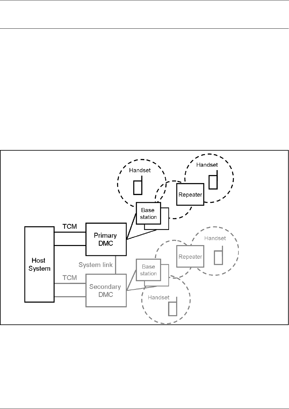
Digital Mobility system diagram
The following figure provides an overview of the whole system.
Figure 1 Digital Mobility system diagram

29 Chapter 1 Overview
N0000623 01.5
General system information
This section provides information about:
•“Components of the system” on page 29
•“Description of connectors and their placement” on page 33
Components of the system
This section provides information about:
•“Digital Mobility Controller (DMC)” on page 29
•“Digital Mobility Base station (RFP)” on page 30
•“Digital Mobility Repeater (WRFP)” on page 31
•“Digital Mobility Handset/DECT Handset (PP)” on page 32
•“Administration and maintenance tools” on page 33
Digital Mobility Controller (DMC)
The Digital Mobility Controller is the mobility system component which connects to the Nortel
host system. The DMC together with the host system handles the routing of telephone calls
between the base stations and the host system.
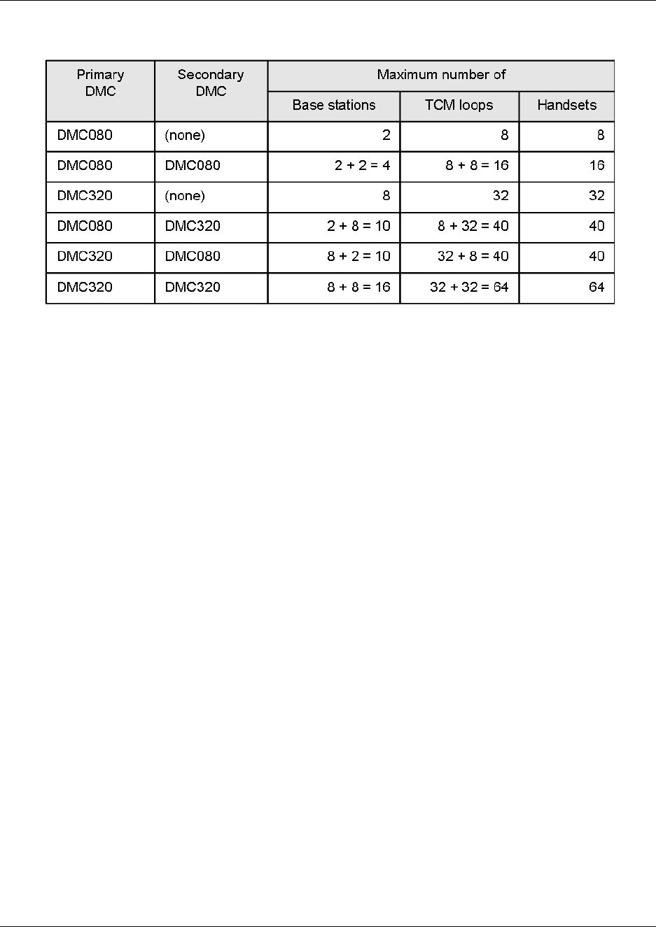
The DMC is available in two versions:
• DMC080 - supporting up to two base stations and eight TCM loops for support of eight
handsets.
• DMC320 - supporting up to eight base stations and 32 TCM loops for support of 32 handsets.
It is possible to link two systems together to make a number of different host system-DMC
configurations:
Chapter 1 Overview 30
Digital Mobility System Installation and Configuration Guide
Table 2 Host system - DMC configurations
See “Digital Mobility system diagram” on page 28 for an illustration of the Primary - Secondary
configuration.
Digital Mobility Base station (RFP)
The base stations are positioned in the area to send and receive calls between the host system and
the handset. The base station contains internal antennas and handles four speech channels
simultaneously. A base station is able to synchronize with other base stations. When the base
station is synchronized with other base stations, a person speaking in a handset can move between
base stations without any interference.
Note: Whether the base station is connected to the Primary or Secondary DMC is of no
importance to the synchronization as a base station is synchronized automatically when
performing cable delay measurement. Refer to “Connecting DMC to host system (TCM loop)” on
page 68 for more information on cable delay measurement.
Transmission length is up to 1.5 km (1 mile) on a twisted standard pair category 4 cable, between
the base station and the DMC. From this connection the base station is supplied with power from
the DMC (max. supply 1.5 W). The radius coverage of the base station is 600 meters (2,000 feet)
with a Digital Mobility handset/DECT handset in free sight.
Coverage area decreases depending on choice of building materials and obstructive elements. To
ensure proper coverage in the areas required, it is necessary to conduct a site survey and
deployment by certified technicians. For more information about deployment, refer to the Digital
Mobility Deployment Guide accompanying the Deployment Kit.
31 Chapter 1 Overview
N0000623 01.5
The host system supports the following wireless base stations:
• Digital Mobility Base station 10 (2.4 GHz frequency band)
• Digital Mobility Base station 14 (1910 - 1930 MHz frequency band)
• Digital Mobility Base station 15 (1880 - 1900 MHz frequency band) (DECT)
• Digital Mobility Base station 19 (1920 - 1930 MHz frequency band)
Refer to “Base station installation” on page 80 BS-19 model (1920 - 1930 MHz frequency band)
Digital Mobility Repeater (WRFP)
The repeater is available as a half slot or full slot repeater. A half slot repeater covers two
simultaneous speech channels; a full slot repeater covers four simultaneous speech channels.
These channels are borrowed from the attached base stations, and are not additional channels to
the system total number of channels. A full slot repeater increases the coverage area. A half slot
repeater also increases the coverage area but with reduced capacity.
Note: The repeater does not increase the traffic capacity. Instead, it increases the radio coverage
area of the system by a maximum of 50 per cent.
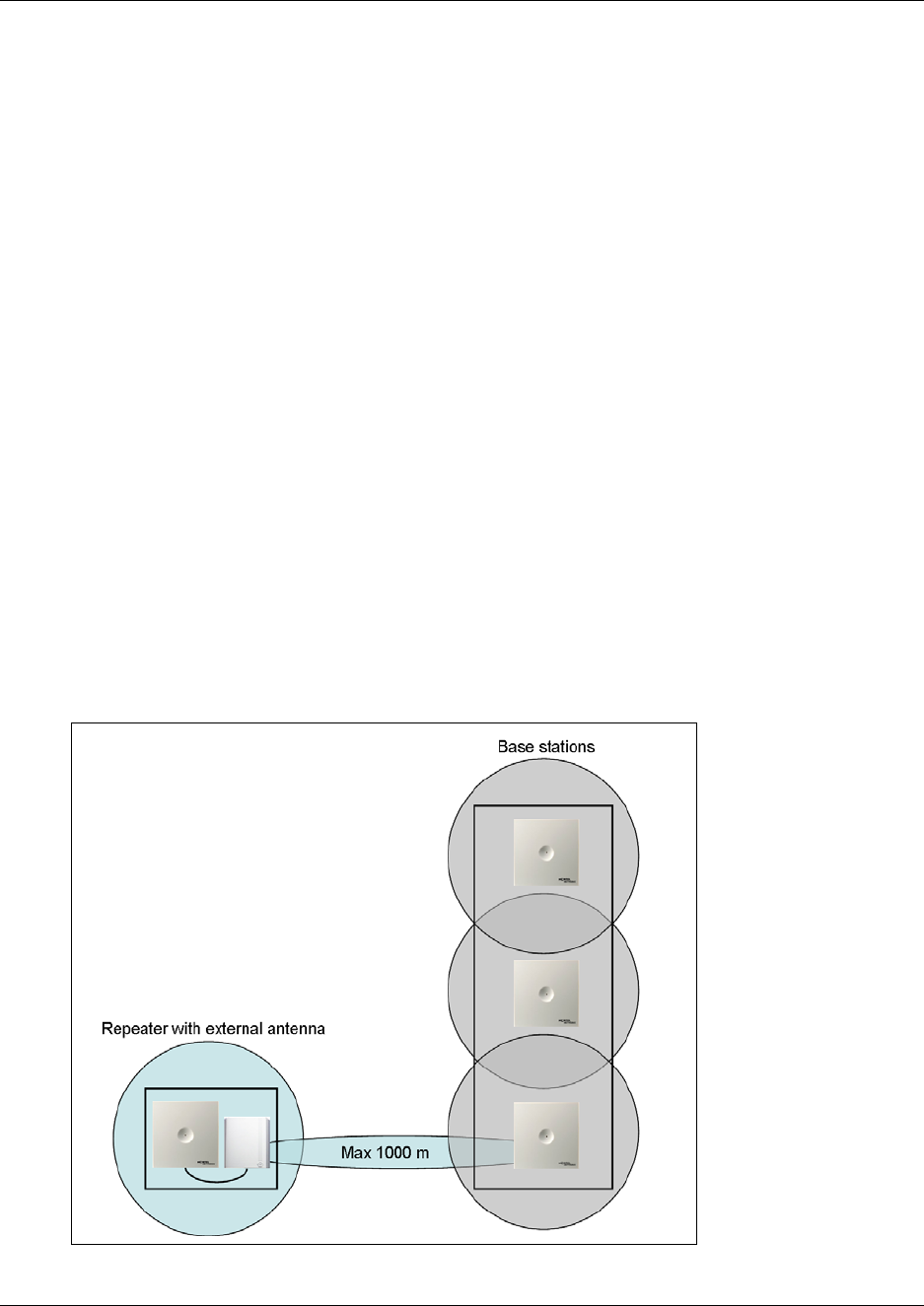
The repeater has two internal antennas which are used for increasing the effective range of a base
station in a certain direction. The repeater is also available with a connector for a third external
antenna (directional antenna) which can be used to create a new coverage cell up to 1000 meters
(3,300 feet) away from the base station.
Figure 2 Repeater with external antenna

Chapter 1 Overview 32
Digital Mobility System Installation and Configuration Guide
The digital repeater relays the radio signals between the handsets and the base station, making it a
wireless component from the DMC.
Note: The repeater is powered with a 9.0VDC - 300mA transformer. Therefore, it needs a power
source within three meters (10 feet). A new coverage zone can not be established via the repeater
with a directional Antenna
The host system supports the following wireless half slot repeaters:
• Digital Mobility Repeater 20 (2.4 GHz frequency band)
• Digital Mobility Repeater 24 (1910 - 1930 MHz frequency band)
• Digital Mobility Repeater 25 (1880 - 1900 MHz frequency band) (DECT)
The host system supports the following wireless full slot repeaters:
• Digital Mobility Repeater 40 (2.4 GHz frequency band)
• Digital Mobility Repeater 44 (1910 - 1930 MHz frequency band)
• Digital Mobility Repeater 45 (1880 - 1900 MHz frequency band) (DECT)
• Digital Mobility Repeater 49 (1920 - 1930 MHz frequency band)
Refer to “Repeater installation” on page 70.
Digital Mobility Handset/DECT Handset (PP)
The host system supports the following wireless handsets:
• DECT Handset 413X
• DECT Handset 414X
• Digital Mobility Handset 7420 (only for use in North America)
• Digital Mobility Handset 743X
• Digital Mobility Handset 744X
where X represents the frequency variant of the models:
• 0 = (2.4 GHz frequency band)
• 4 = (1910 - 1930 MHz frequency band)
• 5 = (1880 - 1900 MHz frequency band) (DECT)
• 6= (1880 - 1900 MHz frequency band) (DECT) (Australia / New Zealand specific parameters)
• 9 = (1920 - 1930 MHz frequency band)
Note: All radio equipment must be of the same variant (eg. 2.4GHz Handsets only operate with 2.4GHz
Base Stations and Repeaters; NA DECT Handsets only operate with NA DECT Base Stations and
Repeaters).
Refer to “Preparing handset for use” on page 88.
Refer to “DECT and DECT variants” on page 21 for more information about DECT and frequency
variants.
33 Chapter 1 Overview
N0000623 01.5
The handsets used with the DMC are uniquely designed as small, lightweight units with an
extensive feature list. Refer to “Host system and handset interoperability” on page 120.
All handsets have a display. The displays has a three-line capacity. Each line is 16 alphanumeric
characters wide. There are also five functional icons that may appear on the display. These features
are described in the Digital Mobility Handset User Guide/DECT Handset User Guide.
Administration and maintenance tools
Programming of the DMC is performed using the DMC OAM program or a Master handset. You
can use either of these to register handsets to the system, check system parameters, and check
messaging profiles. The DMC can be accessed remotely through a modem or IP connection
through a serial-IP converter to perform maintenance and system updates. This part of the OAM
should only be used by certified technicians. Refer to “Connecting a computer to the DMC” on
page 97 for more information about accessing the DMC.
Refer to “Serial port” on page 35 for more information about the serial connection for initial
configuration.
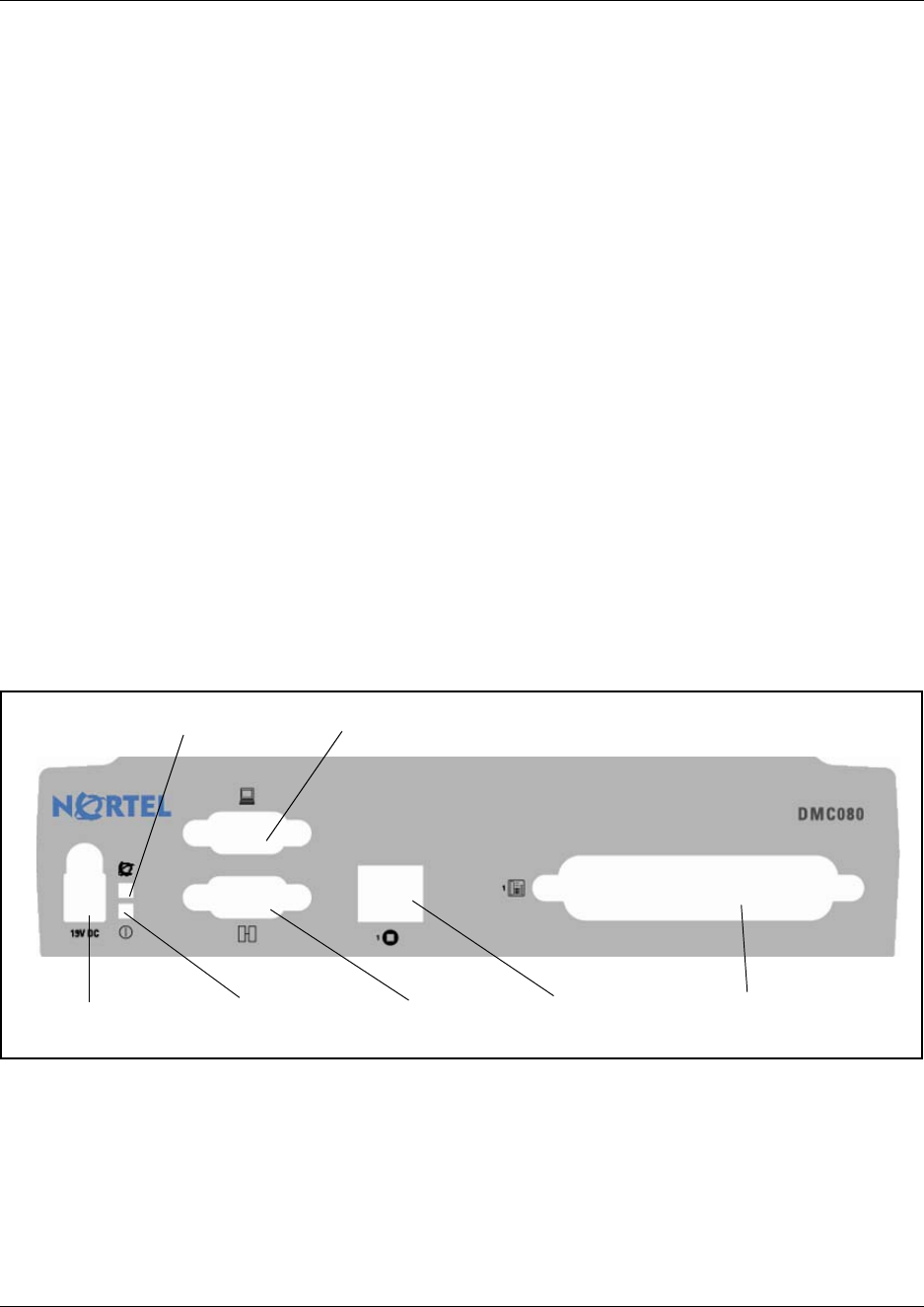
Description of connectors and their placement
On the DMC there is a faceplate with the connections for the wireless system:
Figure 3 Faceplate on DMC080
Power connection Power LED System Link
(Secondary DMC)
Base station
connection
TCM loop
connection
Serial port
CPU Status LED
Chapter 1 Overview 34
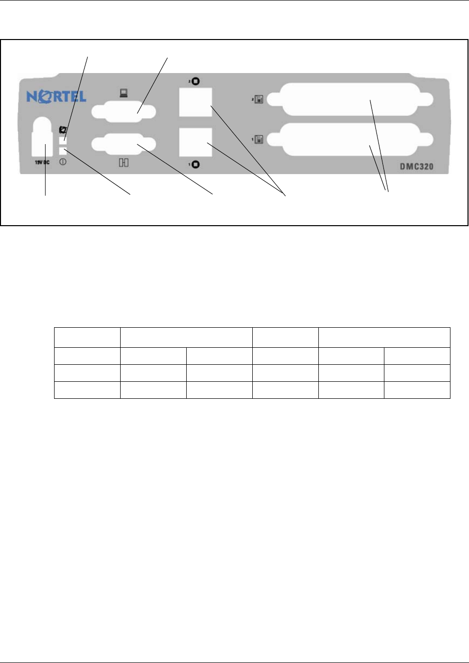
Digital Mobility System Installation and Configuration Guide
Figure 4 Faceplate on DMC320
System Status LEDs
The DMC has two visual status monitor indicators (bi-color LEDs) on the faceplate (Power LED
and CPU Status LED). The functions of the LEDs are given in the table below:
• Initially on power up, the Power LED will be set to Green and the CPU Status LED will be set
to OFF.
• As the boot code starts (takes a few seconds), it will set the CPU Status LED to Green
Flashing.
• When the operating system (OS) is up, the CPU Status LED will be set to Green Solid.
System link (Secondary DMC)
The System link connection is a 9-pin DSUB9 socket for clocks, synch, ADPCM and RS485 link
between the Primary and Secondary DMC. The maximum length of the cable is one meter (3 feet).
Note: To set up a linked system a separate orderable link cable is required.
Table 3 System status monitor indicators
Green LED OFF Red LED
Solid Flashing Solid Flashing
Power OK N/A No Power N/A N/A
CPU Status OK Start No OS Major Issue N/A
Power connection Power LED System Link
(Secondary DMC)
Base station
connection
TCM loop
connection
Serial port
CPU Status LED

35 Chapter 1 Overview
N0000623 01.5
Serial port
The Serial port connector is a male DB9. A null-modem cable is used to connect the computer to
the DMC for initial configuration of the DMC and for maintenance using the DMC OAM
program.
Base station connection
The connection for the base station is a single RJ45 socket on the DMC080. This socket allows a
maximum of two base stations to connect to the DMC. The DMC320 has two RJ45 sockets, one
above the other, which allow a maximum of four base stations to connect to each socket, for a total
of eight base stations per DMC320.
TCM loop connection
The TCM loop connector is a 50-pin amphenol connector with eight TCM loops for the DMC080
and 16 TCM loops for the DMC320. The DMC320 has two TCM connectors which support a total
of 32 TCM loops.
Power connection
The connection to the power supply is 19 V DC.
36
Digital Mobility System Installation and Configuration Guide
Chapter 2
Installation overview
This section gives an overview of the process of installing the Nortel digital wireless system for
host systems. The host system is the Nortel small business system to which the DMC connects.
The section also describes how to install the DMC OAM program and Digital Mobility Service
Tool and provides information on the different configuration tools and their features.
The information in this guide is based on the following understandings:
• A site survey is complete and available, and you determined the exact locations of the base
stations around the site.
• You determined how many handsets that will be required.
• The host system is installed and initialized and has been tested.
The host system hardware must be in place and configured before you can use the handsets to
connect to the host systems. This guide describes the installation of the various pieces of
hardware and software.
This section contains the following information:
•“Installation process map” on page 37
•“Host system setup requirements” on page 38
•“Requirements for the digital mobility system” on page 38
•“Installation prerequisites” on page 43
•“Installing DMC OAM and Digital Mobility Service Tool” on page 44
•“Description of the DMC OAM program interface screen” on page 53
•“Description of the Digital Mobility Service Tool” on page 55
•“Description of the Master handset interface” on page 58
Caution: None of the equipment can be installed outdoors.
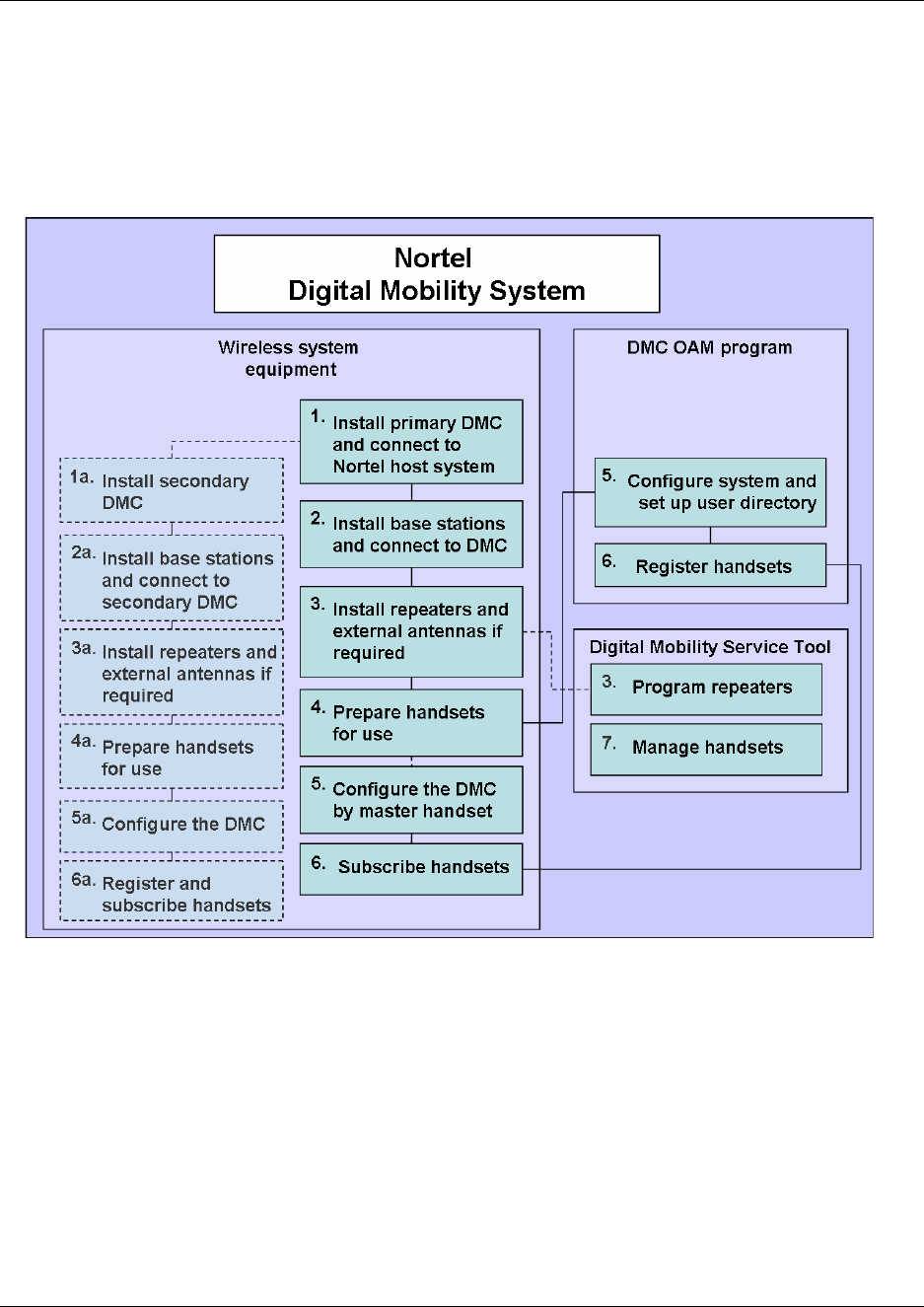
37 Chapter 2 Installation overview
N0000623 01.5
Installation process map
The following figure provides an overview of the process for installing the support hardware and
software for a Nortel Digital Mobility System.
Figure 5 Installing Nortel support hardware and software

Chapter 2 Installation overview 38
Digital Mobility System Installation and Configuration Guide
Host system setup requirements
Requirements for the digital mobility system
This section provides information about the environmental and electrical requirements and
software requirements for the digital mobility system.
The section contains information about the different requirements for:
•“Digital Mobility Controller” on page 38
•“Base stations and repeaters” on page 40
•“Handsets” on page 42
•“DMC OAM program and Digital Mobility Service Tool” on page 42
Digital Mobility Controller
This section provides information you need to know before you install the DMC and contains the
following information:
•“Environmental checklist” on page 39
•“Electrical requirements” on page 39
•“Internal wiring requirements” on page 40
Task Where to find information
Wiring and TCM loop
connections to host system BCM: Installation and Maintenance Guides
Norstar: Installer Guides
Digital station module BCM: Programming and Operations Guides
Norstar: Installer Guides
DN record configuration
Refer to “Telephone settings”
on page 121
Configuring and using features
Refer to “Host system and
handset interoperability” on
page 120.
BCM: Telephony Feature Handbook and Telephone Feature User
Guide
Norstar: System Coordinator Guides and Telephone Feature User
Card
Recording information Programming Records

39 Chapter 2 Installation overview
N0000623 01.5
Before you install the DMC, complete the following actions:
• Determine the location for the DMC and other equipment based on spacing and electrical
requirements. For more information about spacing and electrical requirements, refer to the
“Environmental checklist” on page 39 and the “Electrical requirements” on page 39.
• Check that the number of TCM loops required for the handsets are available on the host
system.
• Ensure that you have all the equipment and supplies you require to install the DMC.
Environmental checklist
The installation area must:
• be minimum of four meters (13 feet) from equipment, such as photocopiers, electrical motors,
and other equipment that produces electromagnetic, radio frequency, and electrostatic
interference
• be within 1.5 meters (5 feet) of a three-wire grounded electrical outlet
• be clean, free of traffic and excess dust, dry, and well ventilated
• be within the temperature ranges of 10°C and 40°C (50°F and 104°F)
• be between 20% and 80% non-condensing relative humidity
• provide enough space and strength to support the DMC
• minimum of 46 cm (20 inches) from the floor
Note: The installation area must be of sufficient height from the floor to prevent water
damage.
Electrical requirements
The following electrical requirements must be met:
• Power must be supplied from a non-switched, unobstructed outlet within 1.5 meters (5 feet) of
the DMC.
• The supplied power must be a dedicated 110 V to 120 V ac nominal (or 220 V to 230 V ac
nominal), 50/60 Hz, 15 A minimum service with a third wire safety ground. The third wire
safety ground provides shock protection and avoids electromagnetic interference.
Danger: Risk of electric shock.
The safety of this product requires connection to an outlet with a third wire ground. Use
only with the supplied DMC power supply and a three wire power outlet.
Caution: Check ground connections.
Ensure that the electrical ground connections of the power utility, telephone lines and
internal metal water pipe system, if present, are connected together. If these ground
connections are not connected together, contact the appropriate electrical inspection
authority. Do not try to make the connections yourself.

Chapter 2 Installation overview 40
Digital Mobility System Installation and Configuration Guide
The DMC power supply cord is 1.5 meters (5 feet) long. You can connect the power cord to a
power bar with a max. length of two meters (6 feet), including power bar. You must use a power
bar approved by an appropriate National Certification Body, with a third wire ground. Do not use
an extension cord between the DMC and the power bar, or between the power bar and the
electrical outlet.
Internal wiring requirements
This section describes the requirements for a TCM (Time Compression Multiplexing) loop between
the DMC and host system.
TCM loop
The following parameters must be met for a TCM loop:
• one twisted-pair cable(s) per handset
• cable length (0.5 mm or 24 AWG) 15 meters (50 feet) or less
• no bridge taps
Base stations and repeaters
This section provides information you need to know before you install the base stations and
repeaters and contains the following information:
•“Environmental checklist” on page 40
•“Electrical requirements” on page 41
Environmental checklist
• Avoid installing base stations and repeaters on large concrete or marble columns because these
columns affect radio coverage. If possible, place the base station a minimum of one meter (3
feet) from these types of columns.
• Do not install a base station or repeater with the antenna housings near metal objects. Be
careful not to damage existing wiring or panels.
• Do not position base stations and repeaters in ducts, plenums, or hollow spaces used to
transport environmental air except where the duct, plenum or hollow space is created by a
suspended ceiling having lay-in panels. When you need more than one base station in a cell to
meet traffic requirements, position the base stations at the same cell center.

41 Chapter 2 Installation overview
N0000623 01.5
• Keep the base station and repeater away from steel constructions.
• Do not position base stations and repeaters directly on metallic surfaces. If possible, place the
base station a minimum of one meter (3 feet) from these types of surfaces.
• Do not position base station and repeaters behind furniture.
• Only position base stations and repeaters where the signal is needed.
• The external antenna used for the transmitter is to be fixed-mounted on indoor permanent
structures providing a separation distance of at least 20 cm (8 inches) from all persons during
normal operation and must not be co-located or operating in conjunction with any other
antenna or transmitter. The external antenna can be placed a maximum of one meter (3 feet)
from the repeater and must be placed in the direction of the base station that the repeater
should synchronize with. If the external antenna and repeater is part of a repeater jump, the
antenna should be directed towards the repeater to be synchronized with.
• The installation area must be clean, free of traffic and excess dust, dry, and well ventilated.
• The installation area must be within the temperature ranges of 10°C and 40°C (50°F and
104°F).
• The installation area must be between 20% and 80% non-condensing relative humidity.
• Minimum distance between two base stations varies depending on material and construction
of buildings, but there must always be a radio coverage overlap between the two base stations.
The time it takes a person to cross the common coverage area must be 10 seconds or more, as
the handset needs time to scan for an alternative base station.
Electrical requirements
The following electrical requirements must be met:
• The base station operate on standard two wired (twisted pair) telephone cable - Cat. 4 or 5 - to
prevent disturbances from other equipment.
• The minimum voltage at the end of the cable where the base station is connected must never
drop below 25Vdc with respect to the current consumption of the base station similar to 18mA
(0.8W).
• The max. radiated output power for the antenna is 1W e.i.r.p.

Chapter 2 Installation overview 42
Digital Mobility System Installation and Configuration Guide
Handsets
This section provides information you need to know before you use a handset and contains the
following information:
•“Environmental checklist” on page 42
•“Electrical requirements” on page 42
Environmental checklist
• The area where the handset is used must be within the temperature ranges of 10°C and 40°C
(50°F and 104°F).
• For correct battery charging, the room temperature must be between 0°C and 25°C (32°F and
77°F). Therefore, the handset must not be placed in direct sunlight. The battery has a built-in
heat sensor which will stop charging if the battery temperature is too high.
• For detailed battery information, refer to “Battery information” on page 89.
• The area where the handset is used must be between 20% and 80% non-condensing relative
humidity.
Electrical requirements
The following electrical requirement must be met:
• The supplied power for the charger must be 110 V to 120 V ac nominal (or 220 V to 230 V ac
nominal), 50/60 Hz.
DMC OAM program and Digital Mobility Service Tool
This section describes the computer and hardware requirements to run the two DMC tools.
Software requirements
The following specifications apply for both the application and the installer files:
• OS: Windows 2000 (SP4), Windows XP (SP3), Windows Vista (SP1)
• CPU: Minimum 400 MHz (2000/XP), 1 GHz (Vista)
• RAM: Minimum 256 MB (2000/XP). 1GB (Vista)
• GPU/Display: XGA (1024 x 768)
• Peripherals: RS232 port
• Hard Disk: Minimum recommended HD size by OS and other installed applications + 25 MB
free space for the application.
Depending on other applications running on the system CPU, RAM and hard disk may vary.

43 Chapter 2 Installation overview
N0000623 01.5
Customer-supplied hardware requirements
• null-modem cable (not included with DMC hardware)
• modem (for remote connection) (optional)
• serial-IP converter (for remote connection) (optional)
Installation prerequisites
Note: In the host system programming records you will find a chart that installers can use to write
down base station number and location, repeater number and location, serial numbers, and ARI
codes.
Note: Make sure that a site survey and deployment have been conducted and that the installer has
access to these plans before proceeding any further.
Before you start the installation you need to find the following information and perform the
following tasks:
• ARI codes (serial numbers) for DMC (see label on the rear of the DMC unit or use the System
Information command under the Settings menu in the DMC OAM program)
• Serial numbers for handsets (see label behind the battery - or press *99984*3/OK on the
handset to display the serial number). Refer to “Reading serial number” on page 93.
• AC codes (authentication codes)
The AC is a customer-defined optional subscription pin code of a maximum of eight digits for
the individual handset. The AC can be used when connecting the handset to the DMC.
• Base stations:
Mark each base station with the number corresponding to the DMC port. This ensures that the
positions of the base stations are known, allowing for easier maintenance of the system.
• Repeaters:
Mark each repeater with the number of the related base station. This way you can easily
configure the system on site.
• Handsets:
To use the DMC handsets, you must first install the radio infrastructure, e.g. base stations and
repeaters to transmit and receive radio signals to and from the handsets. There are no direct
connections between the handset and the system. For more information about base station and
repeater installation, refer to “Base station installation” on page 80 and “Repeater installation”
on page 70.
• Charging battery
When charging the handset battery for the first time, leave the handset in the charger for 14 -
16 hours to ensure that the battery is fully charged and the handset ready for use. Refer to
“Charging battery” on page 92.
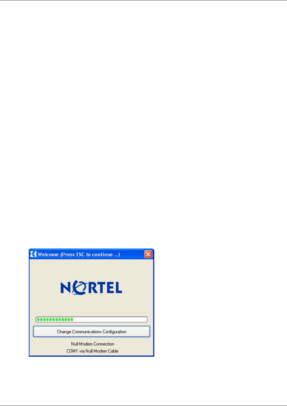
Chapter 2 Installation overview 44
Digital Mobility System Installation and Configuration Guide
Installing DMC OAM and Digital Mobility Service Tool
Where you obtain the DMC OAM and the Digital Mobility Service Tool applications will depend
on the type of host system.
• On Norstar systems (MICS and CICS), you download the installation wizard from the
Modular and Compact ICS Documentation and Client Software CD.
• From Business Communications Manager systems, download the application from under the
Unified Manager Client Install button.
Once you download the applications to your computer, install them by clicking on the
Digital_Mobility_Controller_1.XX.X.XX_setup.exe and
Digital_Mobility_Service_Tool_1.XX.X.XX_setup.exe icon and by following the resulting
Install Wizard prompts.
Starting the DMC OAM program
When you have the DMC OAM application installed, start it from your computer:
1Ensure that the DMC is powered up and connected to a computer.
Refer to “Connecting a computer to the DMC” on page 97 for more information about
connecting a computer to the DMC.
2Double-click the DMC OAM icon or locate the program under the Start menu to open the
DMC OAM program on your desktop.
A start-up window appears.
Figure 6 DMC OAM startup window
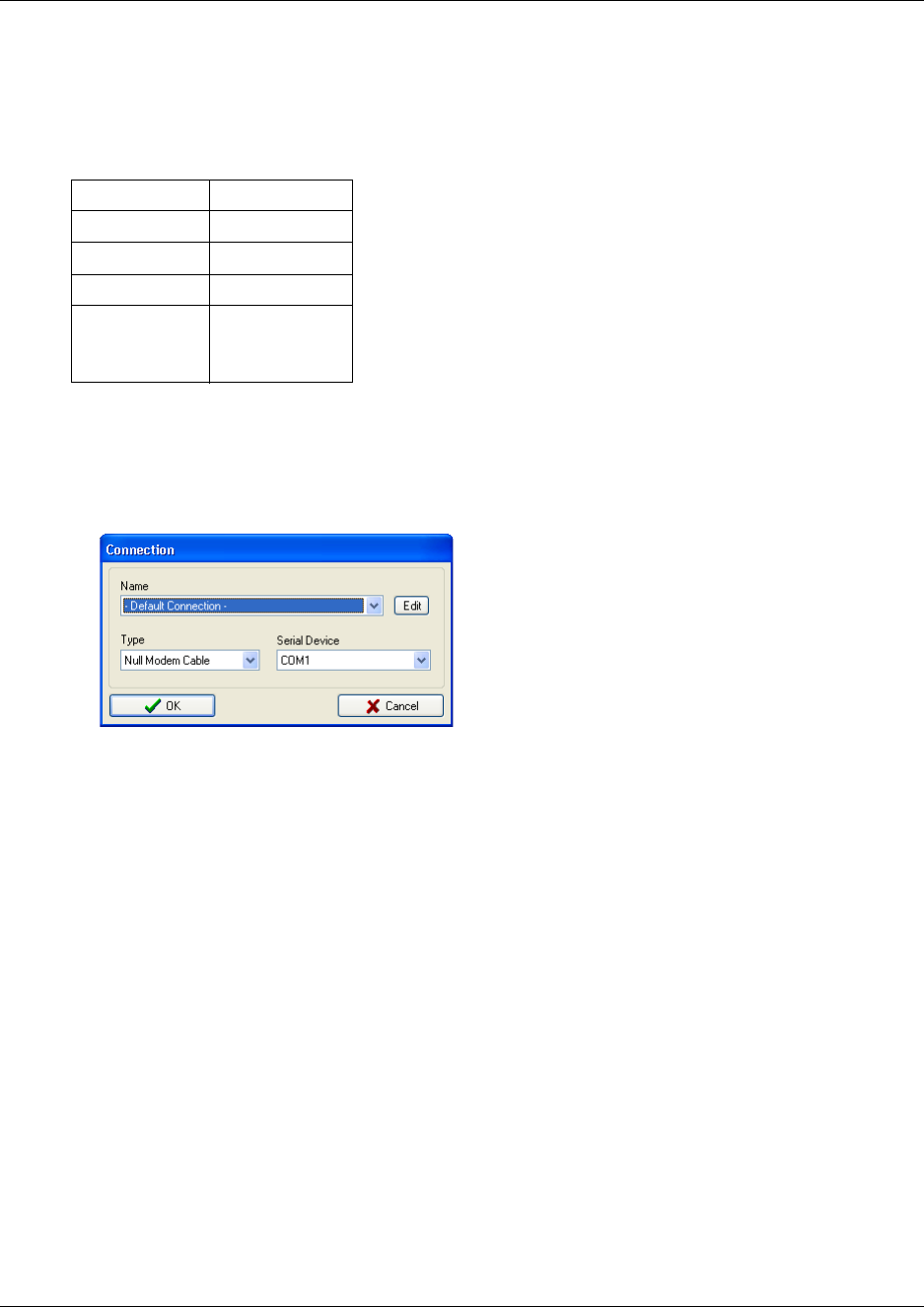
45 Chapter 2 Installation overview
N0000623 01.5
The lower part of the window shows the current communication settings used for connecting
to the DECT system. The default communication setting is COM1 via null-modem cable for
direct connection.
A delay of six seconds gives the user a chance to select a different communication setting, by
clicking Change Communications Configuration.
Figure 7 DMC OAM Connection dialog
You can select between Null Modem Cable, Modem, and Telnet (a Client-Server Protocol
using TCP/IP).
• For modem connection, under Type, select Modem, then under Serial Device, select the
Com port to which the modem is installed, and then click OK.
Table 4 Default Com port setting
Baud: 115200 bit/sec.
Data bit: 8
Parity: None
Stop bit: 1
Flow control: Hardware:
DCD, DSR,
DTR, CTS, RTS
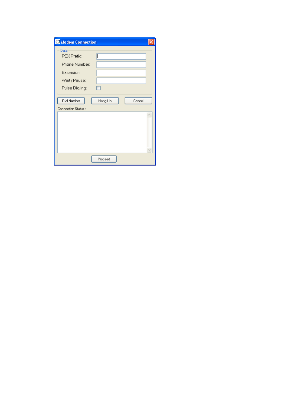
Chapter 2 Installation overview 46
Digital Mobility System Installation and Configuration Guide
A Modem Connection dialog box appears.
Figure 8 DMC OAM: Modem Connection
Under Data enter PBX Prefix (optional), Phone Number, Extension (optional) and
Wait/Pause (optional - depending on the pause needed after entering a PBX Prefix, you
must type one ore more commas. Depending on your PBX, it is also possible to leave the
comma out), and then click Dial Number. When connected to the modem click Proceed.
• For remote connection via a RS232 serial-IP converter, either select:
Null Modem Cable, then select the Com port to which the IP connection has been
installed, and then click OK.
or Telnet, then type the IP Adress and Port in question, and then click OK.
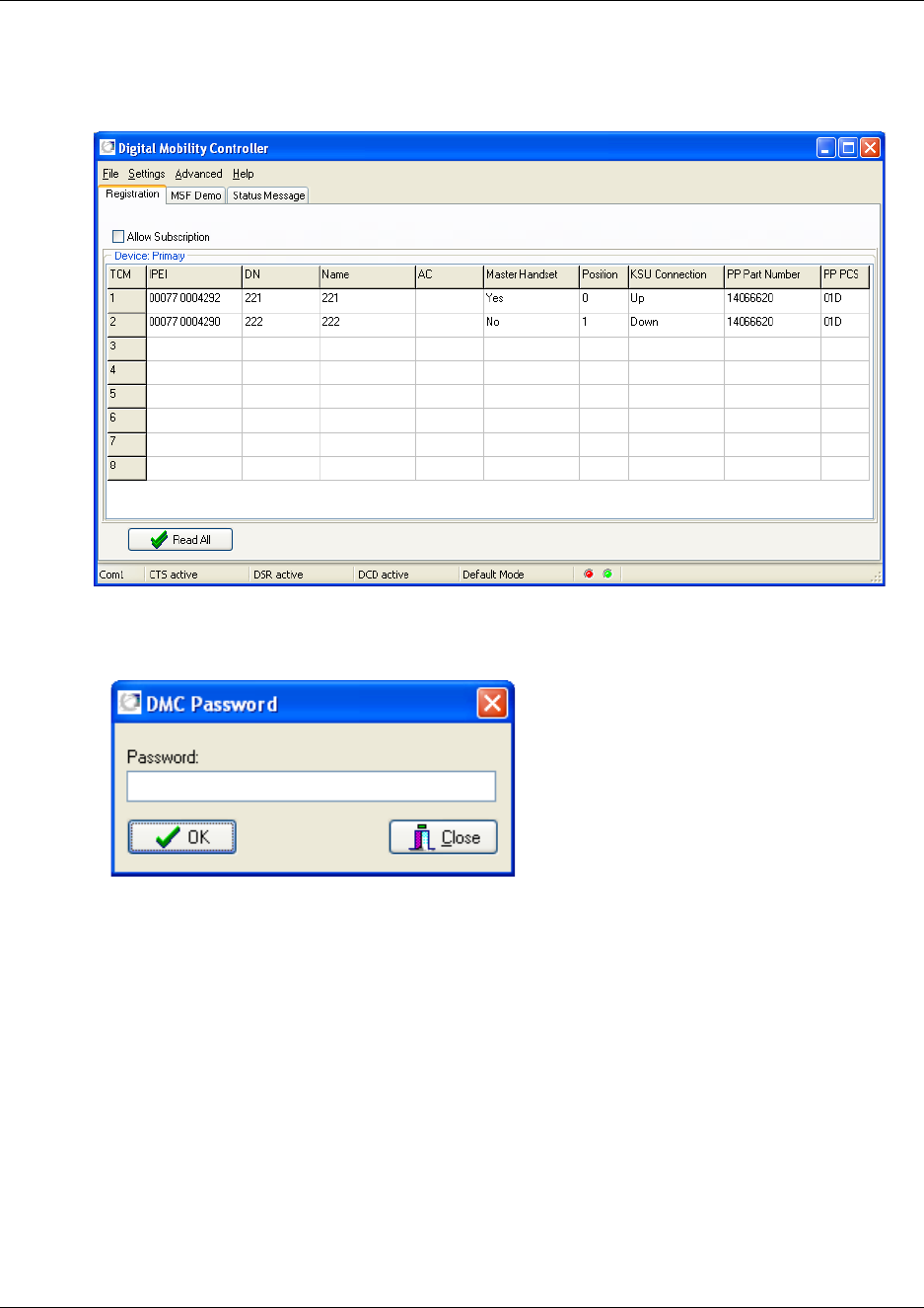
47 Chapter 2 Installation overview
N0000623 01.5
3After a caution message (DMC detected) the DMC OAM program window appears.
Figure 9 DMC OAM: Registration window
4You will be prompted a password to access the program. The default password is:
default.
For information on changing password, see “Change password” on page 102.
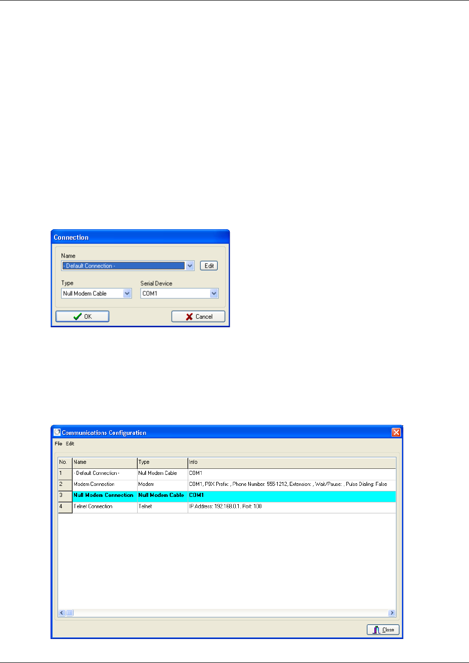
Chapter 2 Installation overview 48
Digital Mobility System Installation and Configuration Guide
Editing communications configurations
You can create new communications configurations, change or delete existing communications
configurations. In the Communications Configuration dialog box it is possible to export and
import the edited communication configurations data from the File menu. You can also save the
file in another location an another name.
Creating a new communication configuration
1To create a new communication configuration either
• Click Change Communications Configuration from the DMC OAM startup window.
A Connection dialog box appears.
Figure 10 DMC OAM Connection dialog
Click Edit.
• or - if the program is already running - on the File menu, click Communications
Configuration.
The Communications Configuration dialog box appears.
Figure 11 DMC OAM Communications Configuration
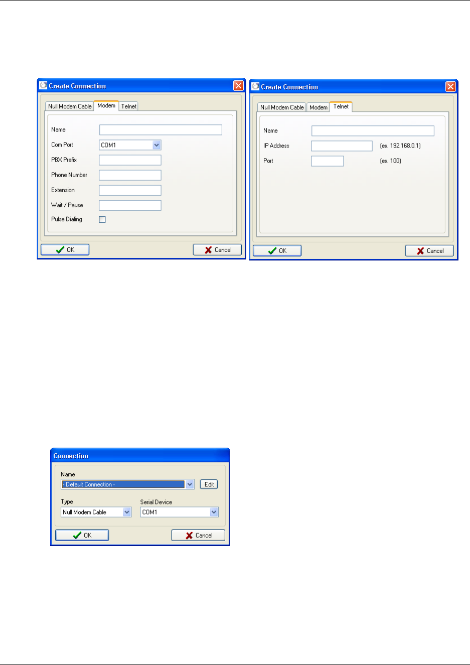
49 Chapter 2 Installation overview
N0000623 01.5
2Alternate-click on a row, and then click Create.
A Create Connection dialog box appears.
Figure 12 DMC OAM Create Connection (Modem tab - Telnet tab)
3Click Null Modem Cable tab, Modem tab or the Telnet tab, and then type the relevant
information. Assigning a name for the communication configuration makes it easier to
distinguish between the different settings.
4Click OK.
Note: To be able to use the new communication setting, it is necessary to disconnect from the
DMC and then reconnect to it.
5From the File menu, click Disconnect from DMC.
6From the File menu, now click Connect to DMC.
The Connection dialog box appears.
Figure 13 DMC OAM Connection dialog
7Select the communication setting in question from the Name list, and then click OK.
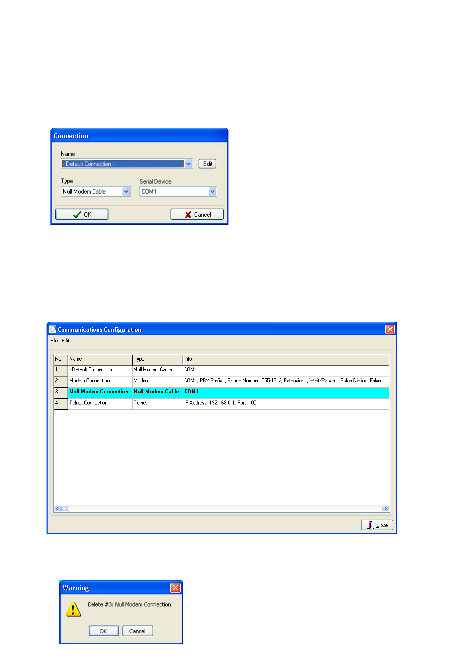
Chapter 2 Installation overview 50
Digital Mobility System Installation and Configuration Guide
Deleting a communication configuration
1To delete a communication configuration either
• Click Change Communications Configuration from the DMC OAM startup window.
A Connection dialog box appears.
Figure 14 DMC OAM Connection dialog
Click Edit.
• or - if the program is already running - on the File menu, click Communications
Configuration.
The Communications Configuration dialog box appears.
Figure 15 DMC OAM Communications Configuration
2Alternate-click on a row containing the communication setting you want to delete, and
then click Delete.
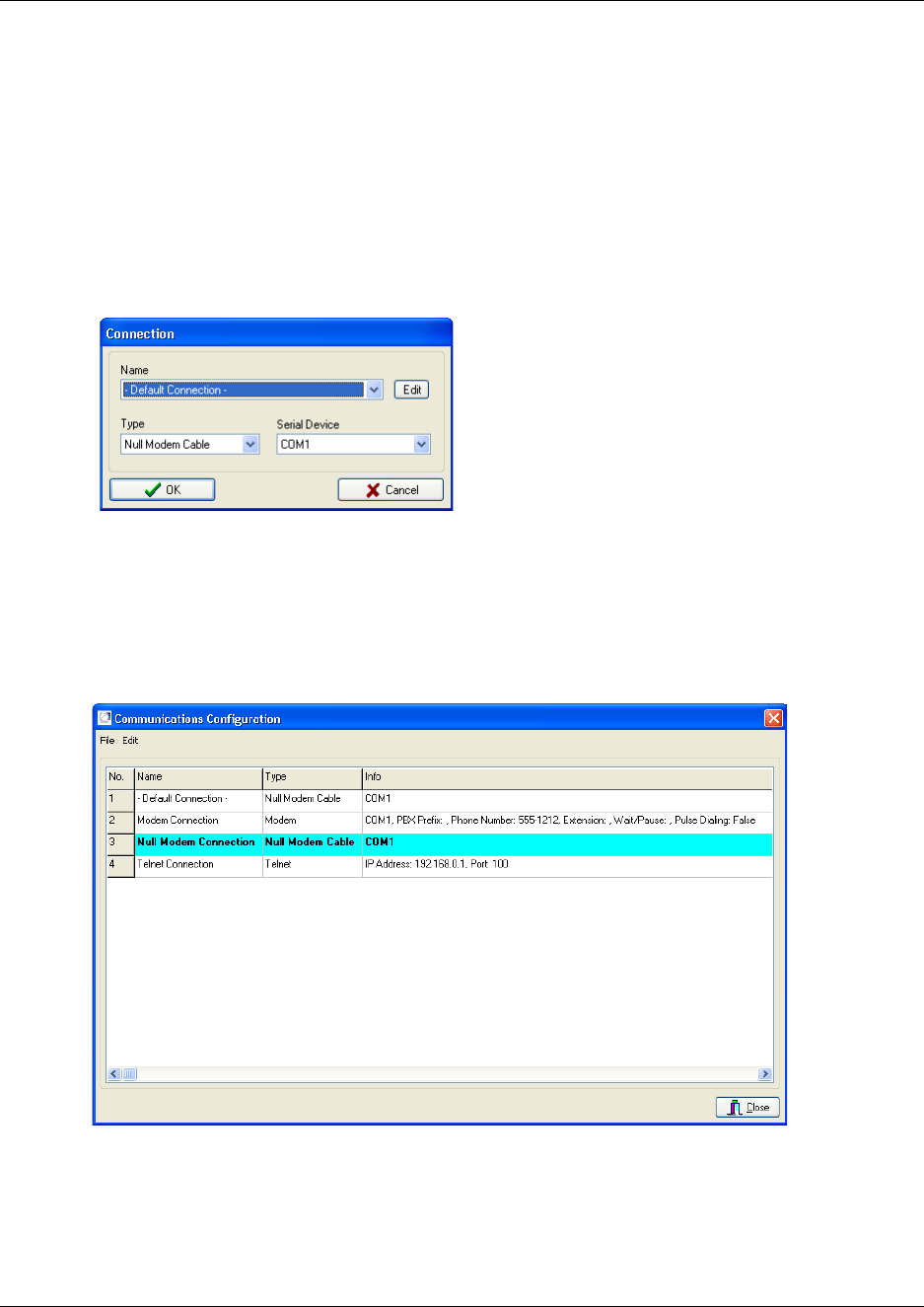
51 Chapter 2 Installation overview
N0000623 01.5
3Click OK to confirm.
Changing a communication configuration
1To change a communication configuration either
• Click Change Communications Configuration from the DMC OAM startup window.
A Connection dialog box appears.
Figure 16 DMC OAM Connection dialog
Click Edit.
• or - if the program is already running - on the File menu, click Communications
Configuration.
The Communications Configuration dialog box appears.
Figure 17 DMC OAM Communications Configuration
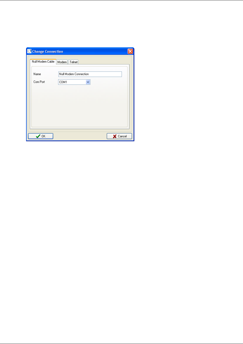
Chapter 2 Installation overview 52
Digital Mobility System Installation and Configuration Guide
2Alternate-click on a row containing the communication setting you want to change, and then
click Change
A Change Connection dialog box appears.
Figure 18 DMC OAM Change Connection.
3Change settings, and then click OK. The Communications Configuration dialog box now
contains the new settings.
Exiting the DMC OAM program
On the File menu, click Exit.
This will quit the DMC OAM program.
Starting the Digital Mobility Service Tool
Connect to the repeater or handset, as described in “Set up of the hardware for repeater
programming:” on page 74 and “Set up of the hardware for handset adjustment:” on page 142.
Perform the following steps to start the Digital Mobility Service Tool application:
1On the desktop, click the Start button
2Point to Programs and find and click on Digital Mobility Service Tool.
A start-up window appears.
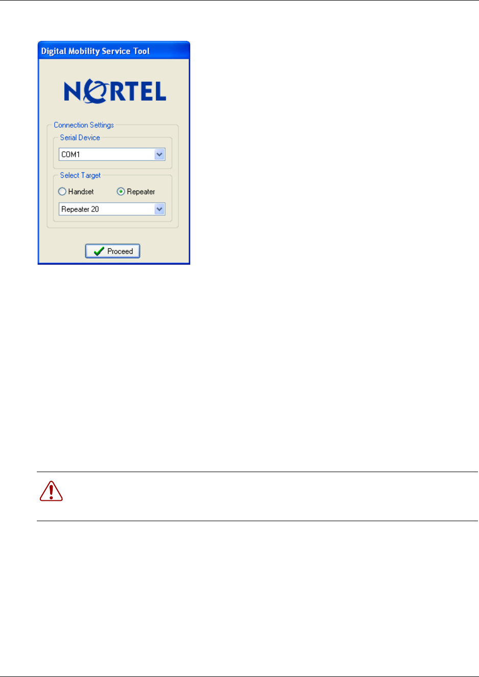
53 Chapter 2 Installation overview
N0000623 01.5
Figure 19 Start-up window for Digital Mobility Service Tool
Exiting the Digital Mobility Service Tool
On the File menu, click Exit.
This will quit the Digital Mobility Service Tool.
Description of the DMC OAM program interface screen
This section provides you with information about the DMC OAM application screens.
With the DMC OAM program you can manage text messages, status information and registration
of handsets. The DMC OAM program also provides maintenance features for maintaining the
system.
The purpose of each window, menu, tab, and command is described in this section.
This section includes information about:
•“DMC OAM program main window” on page 54
•“Understanding the menu” on page 54
•“Understanding tabbed pages” on page 55
Warning: Change the access password to the DMC OAM program at the earliest
opportunity. Refer to “Change password” on page 102 for the procedure for changing
passwords.
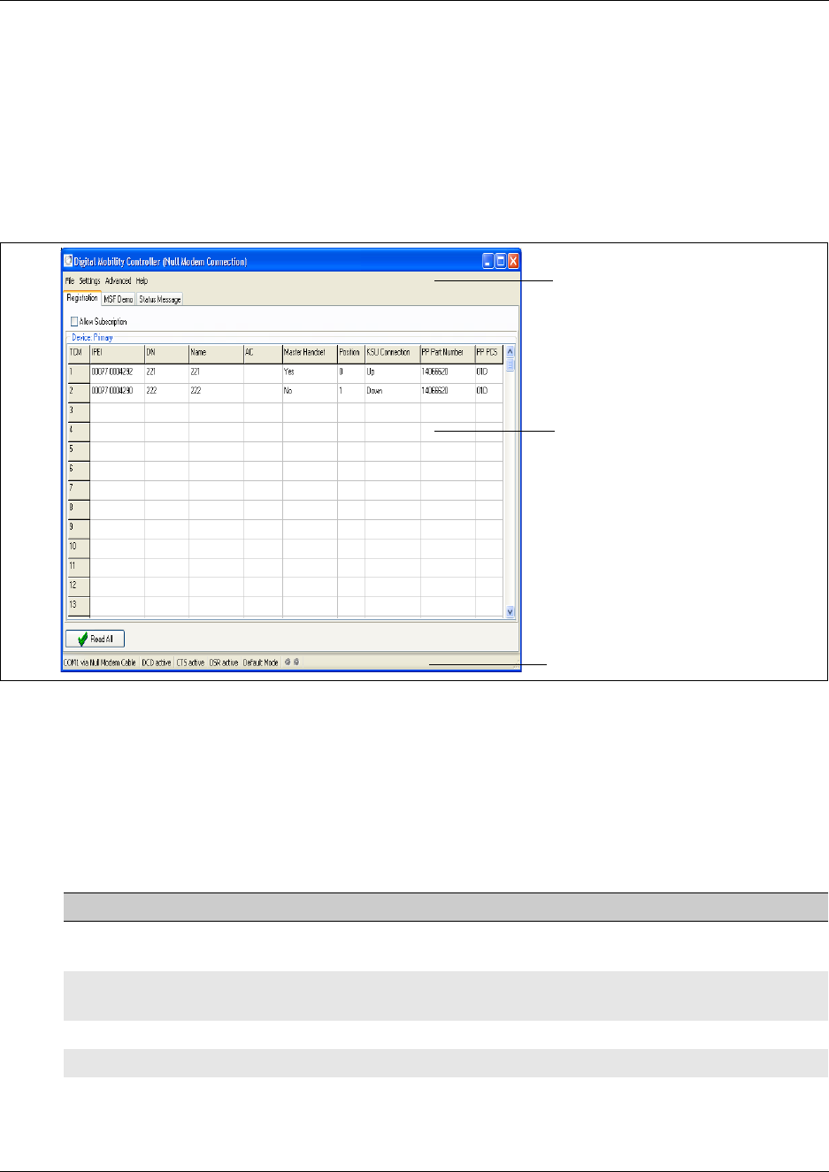
Chapter 2 Installation overview 54
Digital Mobility System Installation and Configuration Guide
DMC OAM program main window
The DMC OAM program main window, shown in the figure below, consists of:
• a menu bar, where users access operation, administration, and management commands
• tabbed pages, where users register handsets, send MSF Messages, and receive status messages
• a status bar, showing status of the different actions going on
Figure 20 Main window of the DMC OAM program
The menu bar contains configuration management options. When you select the different menus
dropdown boxes with commands appear.
Understanding the menu
The following table defines the DMC OAM menu bar top-level items.
Table 5 Menu bar items
Menu item Description
File Exits the program, save configuration data and status message information in
file (for print)
Settings Access information, administration, and management dialog boxes and
screens
Advanced Access administration and management dialog boxes and screens
Help Access system information
Tabbed pages
Menu bar
Status bar
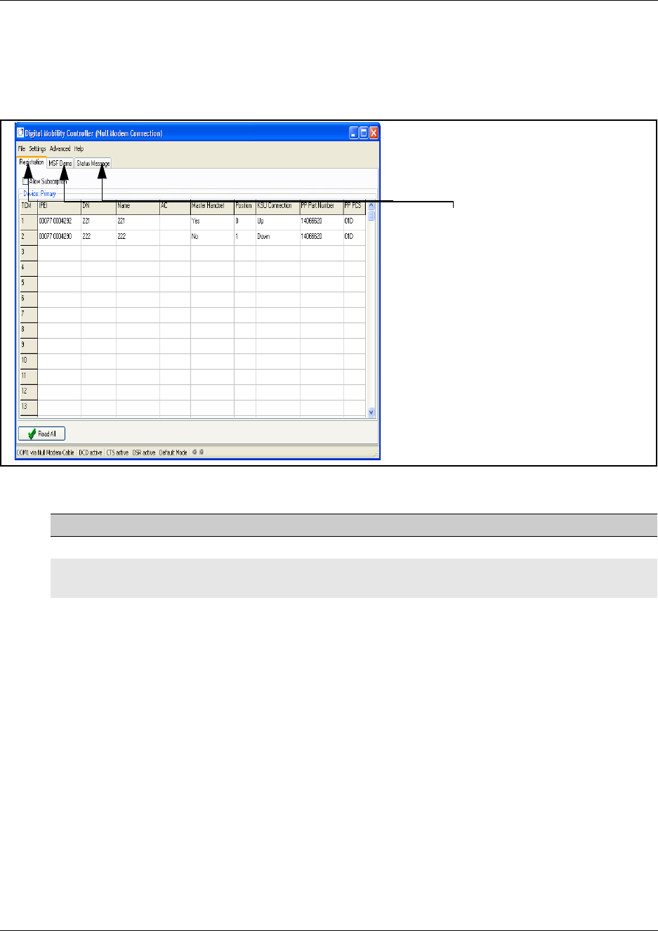
55 Chapter 2 Installation overview
N0000623 01.5
Understanding tabbed pages
The tabbed pages are accessed by clicking the appropriate tab at the top of the screen.
Figure 21 Tabbed page example
Description of the Digital Mobility Service Tool
This section provides you with information about the Digital Mobility Service Tool. This is the
software tool you use on your desktop to access programming for repeaters and handset
management. The Digital Mobility Service Tool is also used for downloading software to the
handsets and repeaters.
The purpose of each menu, tab, and command in the Digital Mobility Service Tool is described in
this section.
This section includes information about:
•“Digital Mobility Service Tool main window” on page 56
•“Understanding the menu” on page 56
•“Understanding tabbed pages” on page 57
Table 6 Tabbed pages
Tab Description
Registration Registration of handsets
MSF Demo Sending text messages to any MSF compatible handset connected to the
DMC
Status Message Reading status messages from the DMC
Tabbed pages
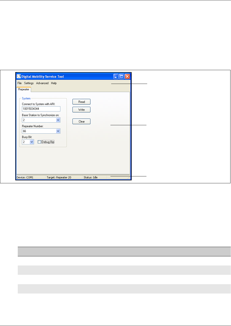
Chapter 2 Installation overview 56
Digital Mobility System Installation and Configuration Guide
Digital Mobility Service Tool main window
The Digital Mobility Service Tool main window, shown in the figure below, consists of:
• a menu bar, where users access operation, administration, and management commands.
• tabbed pages, where users can program repeaters and adjust handset settings.
• a status bar, showing status of the different actions going on.
Figure 22 Main window of the Digital Mobility Service Tool
The menu bar contains configuration management options. When you select the different menus
dropdown boxes with commands appears.
Understanding the menu
The following table defines the Service Tool menu bar top-level items.
Table 7 Menu bar items
Menu item Description
File Exits the program
Settings Choose between Com ports, handset and repeater models
Advanced Software downloads
Help Access system information
Menu bar
Tabbed pages
Status bar
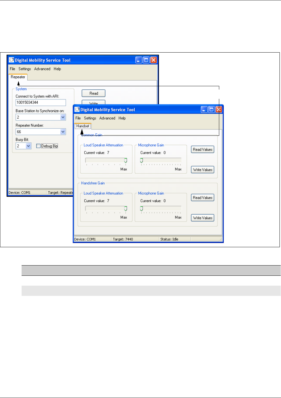
57 Chapter 2 Installation overview
N0000623 01.5
Understanding tabbed pages
Depending on the selected target, the DCM Tool shows a Repeater tab or a Handset tab.
Figure 23 Tabbed page example
Table 8 Tabbed pages
Tab Description
Repeater Programming of repeaters
Handset Handset adjustments
Tabbed page
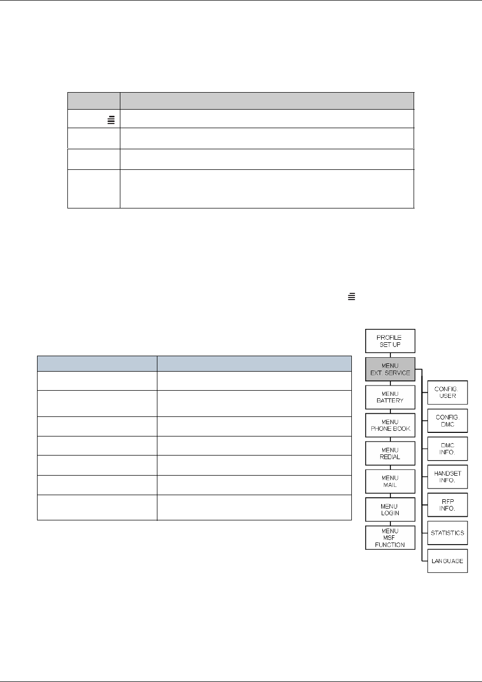
Chapter 2 Installation overview 58
Digital Mobility System Installation and Configuration Guide
Description of the Master handset interface
This section provides you with information about the Master handset interface.
The following keys are used when registering handsets via the Master handset:
Master handset menu structure
Once a Master handset has been subscribed, it has special rights access to the DMC which is used
to configure various settings.
• To access the DMC through the Master handset, press MENU (), use the > key to find
MENU EXT. (EXTERNAL) SERVICE, then press 3/OK.
The first layer of the DMC menu structure through the Master
handset is shown below:
Refer to “Setting up a Master handset (registering and subscribing)”
on page 114 for more information about configuring a Master
handset.
Key Description
Menu key for accessing the menu
>Right arrow key for navigating forward in the menu
<Left arrow key for navigation back in the menu
3/ OK Enter key for accept of menu selection.
You will find the OK -key on model 7420 and the 3-key on model
413X, 414X, 743X and 744X .
MENU Description
Configure user Add/remove/edit/view handset subscriptions
Configure DMC For configuring the DMC through the Master
handset
DMC information View system settings
Handset information View information on all subscribed handsets
Base station information View information on base stations
Statistics Reads out system statistics summary
Languages Set languages for the external service menus
accessible through the Master handset.

59 Chapter 2 Installation overview
N0000623 01.5
Language settings for Master handset
For EXT. SERVICE the Master handset can be set up to use one of three languages. The default
language is English.
To change the default language follow the steps below:
1Press MENU ( ) - go to EXT. SERVICE.
2Press 3/OK - go to LANGUAGE.
3Press 3/OK and select from:
• English
• Spanish
•French
4Press 3/OK to confirm language selection.

60
Digital Mobility System Installation and Configuration Guide
Chapter 3
DMC installation
This section describes how to install the DMC and connect the DMC to the host system.
You can install the DMC in an equipment rack, on a wall or on a desktop.
Figure 24 Install the DMC and connect to host system
This section contains the following information:
•“System equipment for the DMC” on page 61
•“Install a DMC in an equipment rack” on page 62
•“Install a DMC on the wall” on page 64
•“Install a DMC on a flat surface” on page 67
•“Connecting DMC to host system (TCM loop)” on page 68

61 Chapter 3 DMC installation
N0000623 01.5
System equipment for the DMC
The information in this section provides information about the equipment required to install the
DMC. This section contains the following information:
•“Basic hardware” on page 61
•“Optional equipment” on page 61
•“Equipment for installing the DMC” on page 61
Use the checklists in this section to ensure you have all the required equipment.
Basic hardware
Before you install the DMC, ensure you have the correct amount of the following hardware:
• DMC (DMC080 or DMC320)
• One TCM loop available on the host system for each Digital Mobility Handset/DECT Handset
• Digital Mobility base stations
• Digital Mobility repeaters (optional)
• Digital Mobility handsets/DECT handsets
• cable for connections between hardware units
Optional equipment
The following equipment can be ordered separately, depending on your installation requirements:
• Rack mount tray (NT9T6325E5)
• Wall mount bracket (NT9T6700E5)
• Rubber feet
• System link cable (NT7B65LS)
Equipment for installing the DMC
To perform the installation of the DMC, you need the following equipment:
• mounting hardware
(either a rack mounting tray, a wall mount bracket per DMC or four rubber feet per DMC)
• Phillips screwdriver #2
• flat blade screwdriver
• pliers
• antistatic grounding strap
• connecting tool
• surge protector (recommended)
• cables, 25-pair cable with RJ-21 connectors
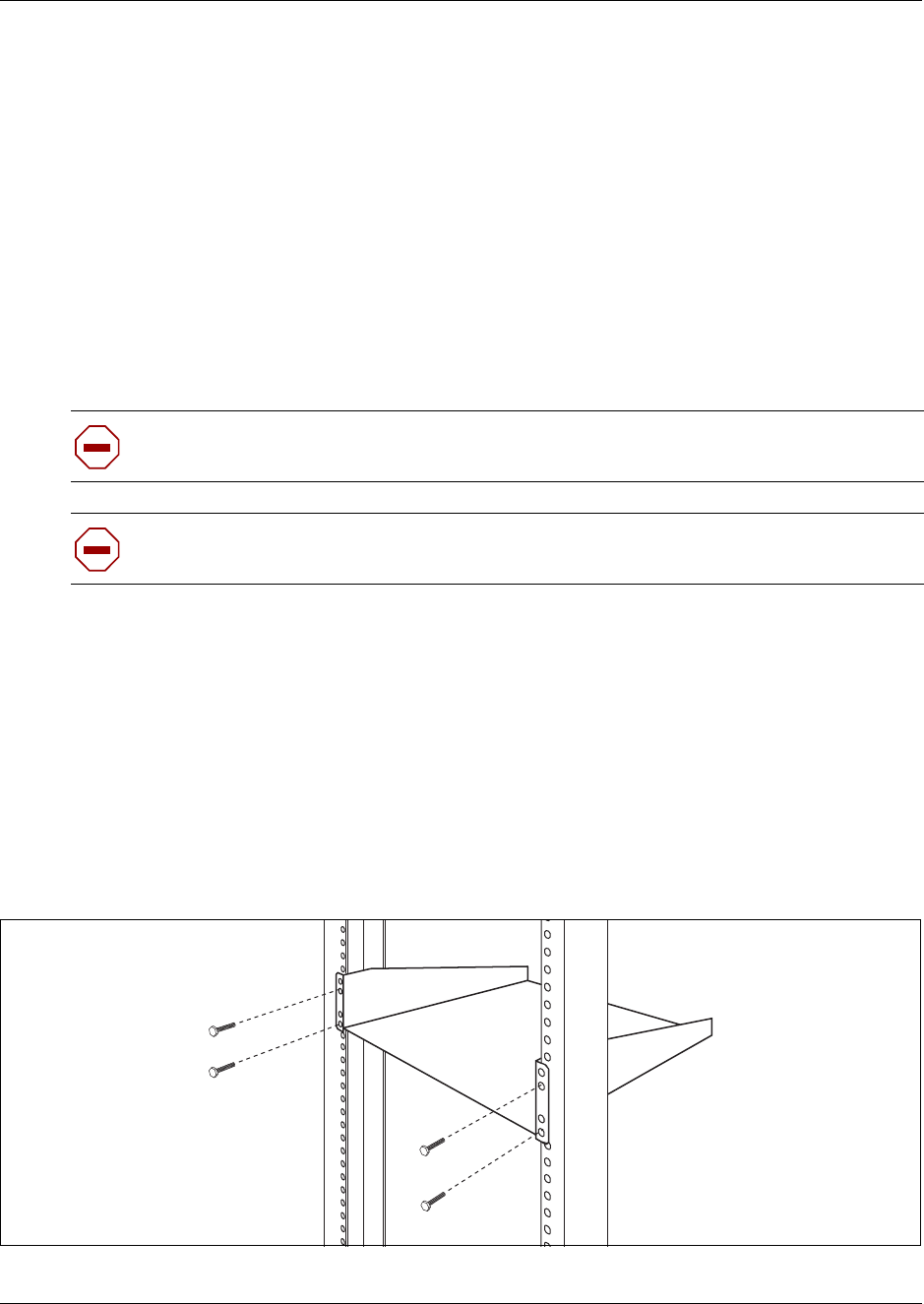
Chapter 3 DMC installation 62
Digital Mobility System Installation and Configuration Guide
Install a DMC in an equipment rack
You can install a DMC in the same rack as your other networking and telecommunications
equipment.
Note: The DMC and the host system must be within 15 meters (50 feet) of each other.
To rack mount a DMC, you need the optional Rack Mount Kit (NT9T6325E5). This kit provides
the parts you need to mount several DMCs into a standard 19-inch equipment rack.
Use the following procedures to mount the DMC in a rack:
•“Install the rack mount tray in an equipment rack” on page 62
•“Install a DMC on the rack mounting tray” on page 63
Install the rack mount tray in an equipment rack
Use this procedure to install the rack mount tray in an equipment rack.
1Determine the location in the rack where you want to install the DMC.
2Position the rack mounting tray in the rack.
3Align the holes in the rack mounting bracket with the holes in the equipment rack rails.
4Fasten the rack mounting brackets to the rack using the four rack screws (supplied).
Figure 25 Fasten the rack mounting tray to an equipment rack
5This procedure is complete.
Caution: Refer to “Installation prerequisites” on page 43 for acceptable environmental
conditions before selecting a location for the DMC.
Caution: To keep the DMC operating at optimal internal temperature, keep the bottom,
sides and rear clear of obstructions and away from the exhaust of other equipment.
63 Chapter 3 DMC installation
N0000623 01.5
Install a DMC on the rack mounting tray
The rack mounting tray has tabs molded into its surface that allow you to clip the DMC to the tray.
By clicking the DMCs to these tabs you can prevent the DMC from accidently being knocked off
of the rack mounting tray.
If you are installing another DMC in a linked system, you can install the second DMC on the tray
beside the first DMC or you can install the second DMC on top of the first DMC.
•“Install a DMC directly on the rack mounting tray” on page 63
•“Install a DMC on another DMC” on page 63
Install a DMC directly on the rack mounting tray
1Place the DMC on the rack mount tray so that the DMC feet are in the depressions in the tray.
Move the module forward so the feet are touching the front side of the depressions.
2Slide the module back until the DMC feet click in place on the tabs in the depressions.
3If you want to further secure the DMC, use four of the plastic screws supplied with the rack
mount kit to attach the DMC to the rack mount tray.
To attach the DMC, ensure that the screw holes in the DMC are aligned with the holes in the
rack mount tray. Then drive the four screws through the holes in the bottom of the tray and into
the screw holes in the bottom of the DMC.
4This procedure is complete.
Install a DMC on another DMC
1Place the DMC on top of the other DMC. Make sure that the DMC feet are in the slots on the
top of the DMC, and in front of the tabs.
2Slide the DMC back until it clicks in place on the tabs. Refer to the figure below.
3Connect the two DMC’s by using the Digital Mobility Link cable (N0008570). See
“Description of connectors and their placement” on page 33 and “System link (Secondary
DMC)” on page 34 for more information on the system link connection...
Caution: Use only the screws supplied with the Rack Mount Kit (NT9T6325E5). Do
not replace the screws. Other screws may damage the module.
Warning: The Primary DMC will reset when the Secondary DMC is connected
regardless of whether the Secondary DMC is powered up or not.
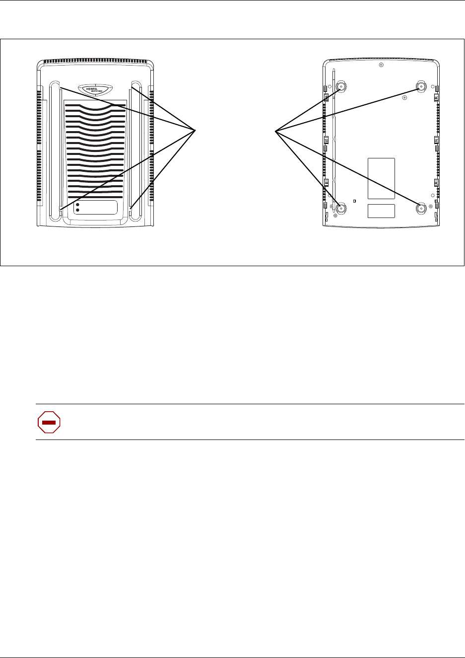
Chapter 3 DMC installation 64
Digital Mobility System Installation and Configuration Guide
Figure 26 DMC tabs
Install a DMC on the wall
This procedure describes how to mount a DMC on a wall.
To mount a DMC on the wall, you need:
• a Wall Mount Bracket kit (NT9T6700E5)
• a plywood backboard two cm (3/4 inch) thick. Consult Local Electrical Code
1Mark the location of the plywood backboard on the wall using a pencil. Use a ruler and
bubble-level to check that the plywood backboard is level.
2Mount the plywood backboard securely to the wall.
3Place the wall mount bracket on the backboard and use a bubble-level to check that the wall
mount bracket is level.
4Using the wall mount bracket as a template, mark the location of three of the wall mount
bracket holes on the plywood backboard. Refer to the following figure.
Caution: Refer to “Installation prerequisites” for acceptable environmental conditions
before selecting a location for the DMC.
Tabs Feet
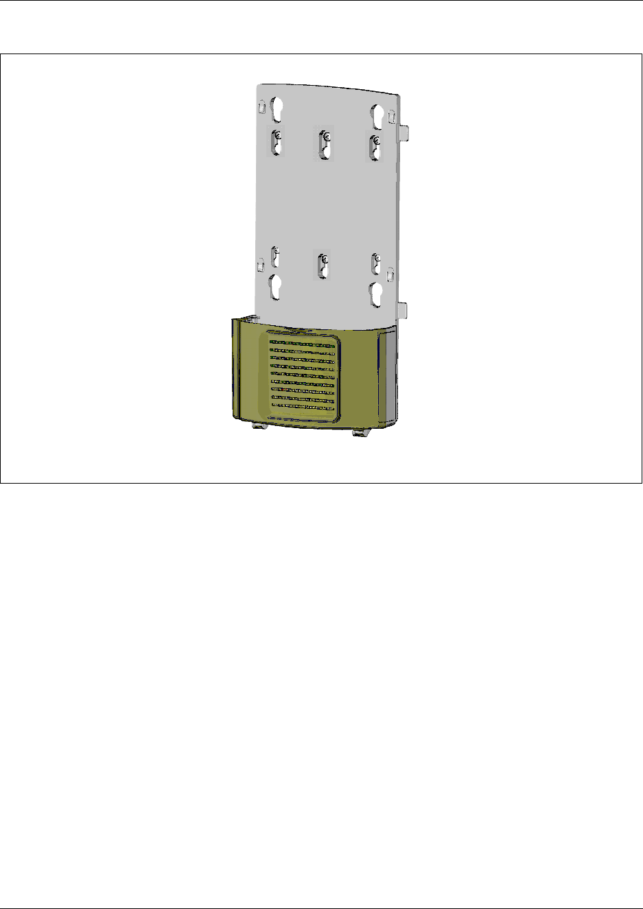
65 Chapter 3 DMC installation
N0000623 01.5
Figure 27 Wall mount bracket
5Install three #10 x 2.5 cm (1 inch) round-head wood screws in the backboard.
Do not tighten the screws heads against the backboard. Leave approximately 0.5 cm (1/5 inch)
of the screw exposed from the backboard.
6Prepare the wall mount bracket by removing the alignment tabs or the side breakouts on the
cable management door. The list below describes what to remove for each of the installation
scenarios.
• If this is the only DMC in the system, remove the alignment tabs on the right side of the
wall mount bracket.
• If this is the first DMC on a system with two DMCs (a linked system), remove the side
breakout from the right side of the cable management door.
• If this is the last DMC on a system with two DMCs (a linked system), remove the
alignment tabs and the side breakout from the left side of the cable management door.
7Hang the wall mount bracket on the mounting screws. Make sure the wall mount bracket is
level and the wood screw heads seat fully into the wall mount bracket slots.
8Tighten the wood screws against the wall mount bracket.
1
1
1
2
2
2
Note: When using three screws,
Nortel recommends installing
the screws in the three holes
labeled “1” or the three holes
labeled “2”.
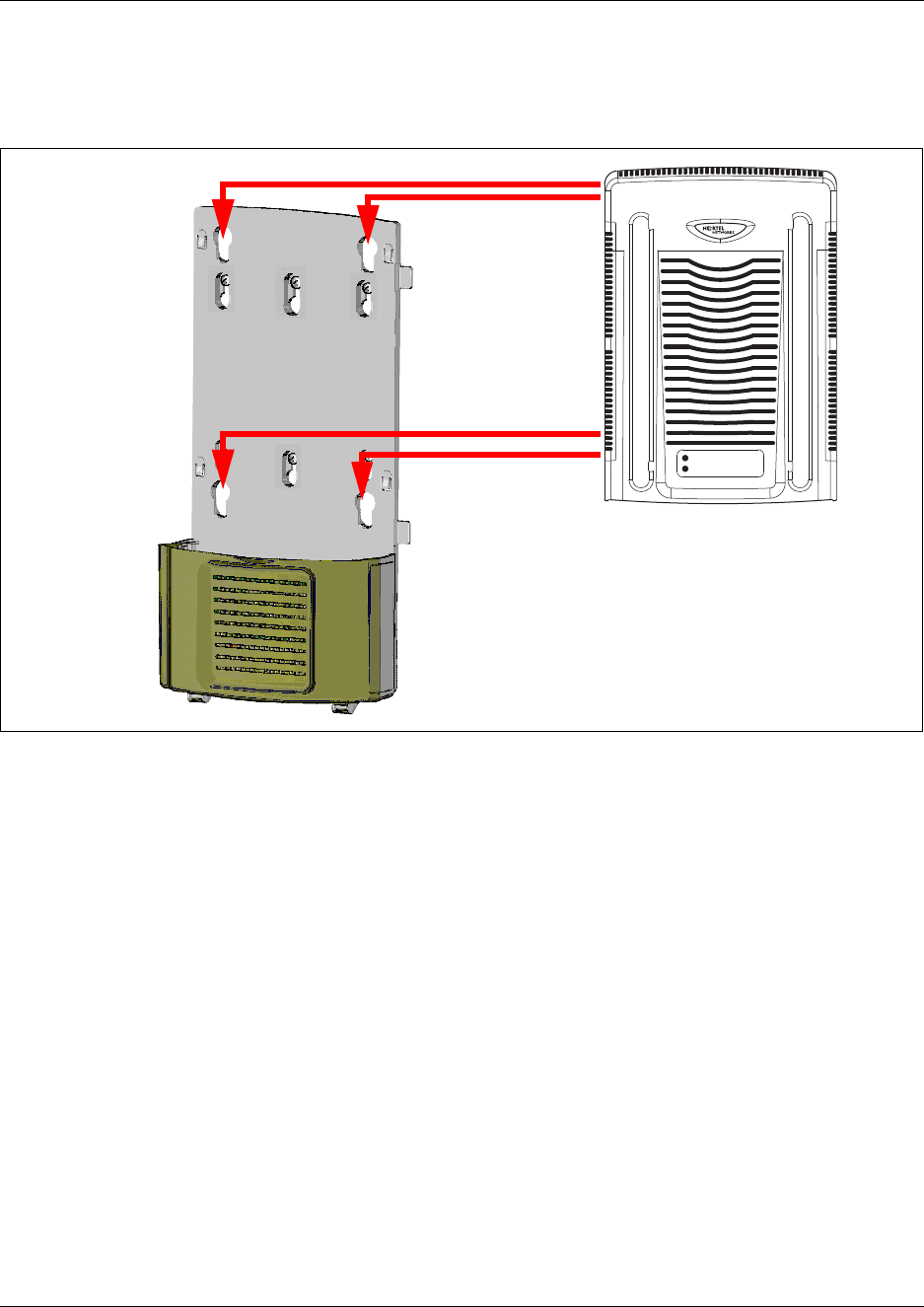
Chapter 3 DMC installation 66
Digital Mobility System Installation and Configuration Guide
9Align the feet on the DMC with the four holes in the wall mount bracket. Refer to the
following figure.
Figure 28 Attach the DMC to the wall-mount bracket
10 Press the DMC against the wall mount bracket and slide the module down until it clicks in
place.
11 Repeat steps 3 and 10 if you are installing a second DMC in a linked system.
12 Secure the power supply for each unit in such a way that it is secure and cannot be accidentally
bumped and dislodged.
13 This procedure is complete.
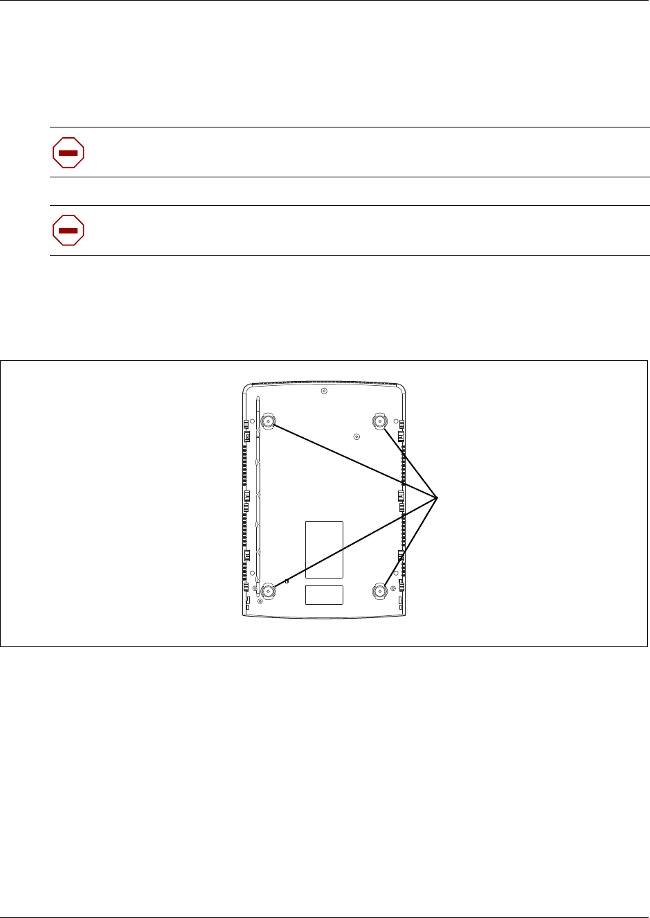
67 Chapter 3 DMC installation
N0000623 01.5
Install a DMC on a flat surface
Use this procedure to install a DMC on any flat surface that can safely support the weight of the
modules.
To install the DMC on a table or shelf:
1Attach the four rubber feet to the bottom of the DMC.
Figure 29 Location for feet on bottom of the DMC
2Position the DMC on the table or shelf. Make sure you leave enough space around the DMC
for ventilation and access to the cables.
3If the DMC is part of a linked system, you can install the other DMC on top of, or beside, the
existing DMC.
• To install the second DMC beside the existing DMC, repeat steps 1 and 2.
• To install the second DMC on top of the existing DMC, refer to “Install a DMC on another
DMC” on page 63.
4Secure the power supply for each unit in such a way that it is secure and cannot be accidentally
bumped and dislodged.
5This procedure is complete.
Caution: Refer to “Installation prerequisites” for acceptable environmental conditions
before selecting a location for the DMC.
Note: Do not place anything directly on top of the DMC (except for another DMC). The
DMC requires the ventilation holes to be free of obstructions to prevent overheating.
Attach feet here

Chapter 3 DMC installation 68
Digital Mobility System Installation and Configuration Guide
Connecting DMC to host system (TCM loop)
This section describes how to connect the DMC to the host system through TCM loop
connections.
TCM Loop connections
The TCM loop connector is a 50-pin amphenol connector with eight TCM loops for the DMC080
and 16 TCM loops for the DMC320. The DMC320 has two TCM connectors which support a total
of 32 TCM loops. Refer to “Description of connectors and their placement” on page 33.
Note: The maximum length of TCM loops is 15 meters (50 feet).
TCM input connector pinout
Below you will find a list of TCM input connector pinouts.
Table 9 TMC input connector pinout
DMC320 Connector 1 DMC320 Connector 2
TCM Loop PIN TCM Loop PIN
1 1 and 26 17 1 and 26
2 2 and 27 18 2 and 27
3 3 and 28 19 3 and 28
4 4 and 29 20 4 and 29
5 5 and 30 21 5 and 30
6 6 and 31 22 6 and 31
7 7 and 32 23 7 and 32
8 8 and 33 24 8 and 33
9 9 and 34 25 9 and 34
10 10 and 35 26 10 and 35
11 11 and 36 27 11 and 36
12 12 and 37 28 12 and 37
13 13 and 38 29 13 and 38
14 14 and 39 30 14 and 39
15 15 and 40 31 15 and 40
16 16 and 41 32 16 and 41

69 Chapter 3 DMC installation
N0000623 01.5
Refer to “Description of connectors and their placement” on page 33 for more information on the
placement of connectors.
Next steps
To install base stations, go to Chapter 5.
To install repeaters, go to Chapter 4.
To prepare handsets, go to Chapter 6.
To configure the DMC, go to Chapter 7.
To register and subscribe handsets, go to Chapter 8.
DMC080 Connector 1
TCM Loop PIN
1 1 and 26
2 2 and 27
3 3 and 28
4 4 and 29
5 5 and 30
6 6 and 31
7 7 and 32
8 8 and 33
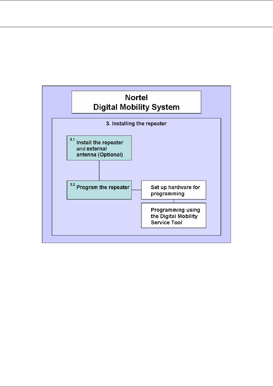
70
Digital Mobility System Installation and Configuration Guide
Chapter 4
Repeater installation
This section describes the process of installing repeaters. Installing repeaters requires a software
installation as well as a hardware installation.
Figure 30 Install the repeater
This section provides information about:
•“Installing the repeater and external antenna” on page 72
•“Programming a repeater with the programming kit” on page 74
•“Description of LED behavior on repeater” on page 79
Note: Before beginning the installation, determine the position of the repeater for best coverage.
The coverage depends on the construction of the building, architecture, and the choice of building
materials. Refer to “Environmental checklist” on page 40 for more information about
environmental requirements for repeaters.
For more information about deployment, refer to the Digital Mobility Deployment Guide
accompanying the Deployment Kit.
Note: Use only the approved power supply provided with the Repeater unit. Do not make any
substitutions.

71 Chapter 4 Repeater installation
N0000623 01.5
Note: The repeater does not add channels, it only adds additional coverage area.
Note: The repeater can only be registered on the system 1) when placed within the coverage area
of a base station 2) when placed within the coverage area of an already-installed repeater or 3)
when placed outside the coverage area using an external antenna.
Note: The repeater covers four simultaneous speech channels. These channels are borrowed from
the attached base stations, and are not additional channels to the total number of channels on the
system.
The repeater can be fitted with an external antenna to increase the coverage area further.
Professional installation is required for the external antenna. Refer to “Digital Mobility Repeater
(WRFP)” on page 31 for an illustration of a repeater with external antenna.
Note: The external antenna used for the transmitter is to be fixed-mounted on indoor permanent
structures providing a separation distance of at least 20 cm (8 inches) from all persons during
normal operation and must not be co-located or operating in conjunction with any other antenna or
transmitter.
Note: The external antenna can be placed max. one meter (3 feet) from the repeater and must be
placed in the direction of the base station that the repeater should synchronize with. If the external
antenna and repeater is part of a repeater jump, the antenna should be directed towards the repeater
to be synchronized with.
The external antenna comes with a wall mounting holder into which the external antenna can be clipped on
to the main unit.
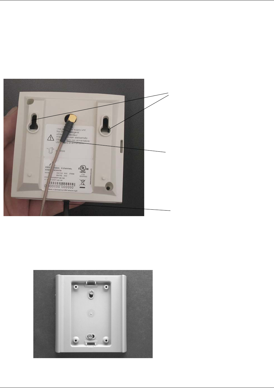
72
Installing the repeater and external antenna
1Connect the power supply cable into the RJ11 connector in the bottom of the repeater.
To connect the external antenna to the repeater, break off the tab covering the antenna
connection at the rear of the repeater and connect the external antenna cable .
Figure 31
2Mount the repeater onto the wall using the screws accompanying the repeater.
3To install the external antenna, mount the wall bracket for the external antenna on the
wall using the accompanying 30mm screws.
Figure 32
Power supply cable
External antenna cable (Only for
repeaters supplied with external antenna
conncetion)
Holes for wall mounted screws
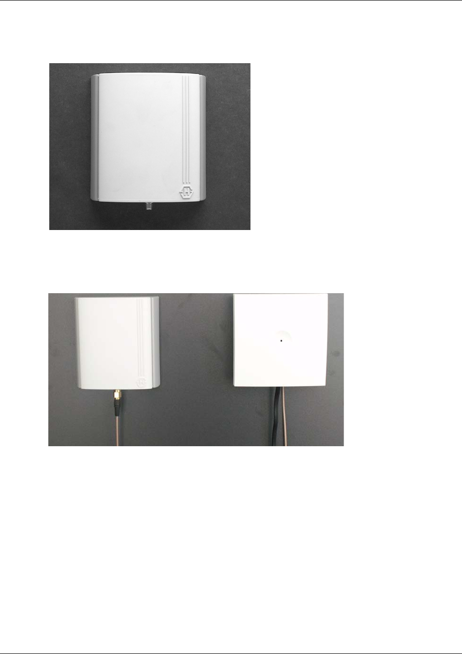
73
N0000623 01.5
4Clip the antenna into position.
Figure 33
5Connect the antenna cable at the rear of the repeater with the connection plug at the bottom of
the external antenna.
Figure 34
Note: If you need to remove the external antenna, unclick the antenna from the wall bracket with
a gentle pull.
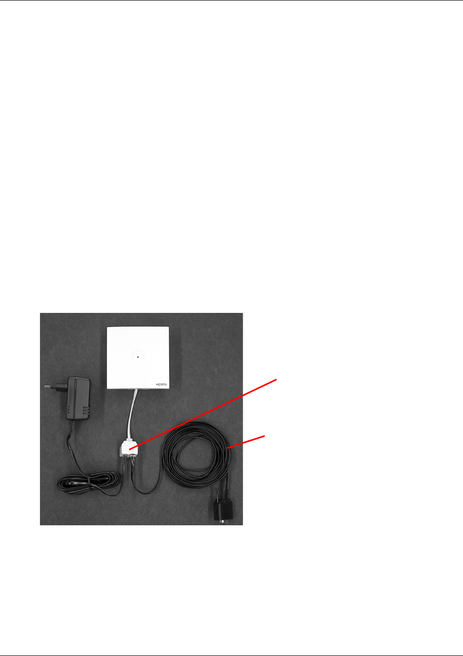
74
Programming a repeater with the programming kit
This section provides information about:
•“Content of the programming kit:” on page 74
•“Set up of the hardware for repeater programming:” on page 74
•“Programming the repeater with the Digital Mobility Service Tool” on page 75
Content of the programming kit:
The programming kit (NT7B65LK) consists of:
• modular connector adaptor
• serial cable
Note: For programming the repeater you also need the programming software (Digital Mobility
Service Tool). The Digital Mobility Service Tool is not part of the programming kit but can be
found on the host system CD (Norstar systems) or under the Client Install button on the Business
Communications Manager Unified Manager application.
Figure 35
Set up of the hardware for repeater programming:
1Unplug the repeater power cable and insert the modular connector adaptor.
2Connect the repeater power cable to the modular connector adaptor and the mains.
Note: Ensure that you have the appropriate power supply for the local requirements.
modular connector adaptor
serial cable
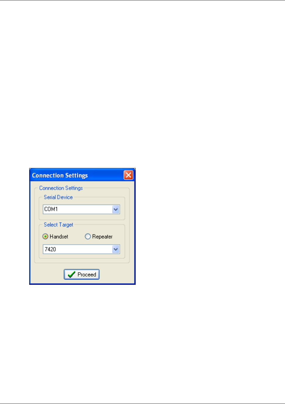
N0000623 01.5
Connect the serial cable to the modular connector adaptor and Com port of your computer.
The repeater is now ready for programming via the Digital Mobility Service Tool.
Programming the repeater with the Digital Mobility Service Tool
The Digital Mobility Service Tool is the tool you access from your desktop and use for repeater
programming, handset adjustment and software download to the handset and repeater. For a
detailed explanation of the Digital Mobility Service Tool, refer to “Description of the Digital
Mobility Service Tool” on page 55.
Before you start programming the repeater, ensure that the repeater is connected to the
computer and the mains. Refer to “Set up of the hardware for repeater programming:” on page
74.
Open the Digital Mobility Service Tool on your desktop.
A Digital Mobility Service Tool window appears.
Figure 36
3Select a Com port from the Serial Device list.
4Click Repeater, and then select the wanted repeater model from the list.
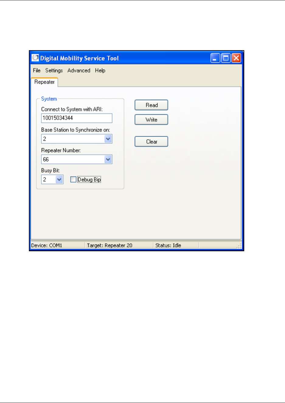
76
5Click Proceed.
The Repeater configuration screen displays.
Figure 37
A message displays in the status bar when repeater is connected.
6In the Connect to System with ARI field, type the DMC ARI code.
The ARI code is an 11-digit serial number for the DMC. The number is located on the label on
the rear of the DMC. You can also read the ARI code using the System Information
command under the Settings menu in the DMC OAM program.
Refer to “Installation prerequisites” on page 43.
7In the Base to synchronize on field, select the number of the base station which the repeater
must synchronize with.
Refer to “Installation prerequisites” on page 43.

Chapter 4 Repeater installation
N0000623 01.5
In the Repeater number field, select the assigned number of the repeater
The numbering of the base station and repeaters has to follow the numbering shown in the
tables below.
Repeater and base station numbers must not be the same. Neither can the repeater have
a number similar to another base station or another repeater in a situation where common
overlap is present between the actual units. If this occurs, handover between the different units
is not possible.
Refer to “Installation prerequisites” on page 43.
Table 10
Base station Repeater 1 Repeater 2 Repeater 3
0 64 128 192
1 65 129 193
2 66 130 194
3 67 131 195
4 68 132 196
5 69 133 197
6 70 134 198
7 71 135 199
8 72 136 200
9 73 137 201
10 74 138 202
11 75 139 203
12 76 140 204
13 77 141 205
14 78 142 206
15 79 143 207
Example of a normal base station/repeater configuration
Numbering of base station and repeaters in a normal configuration
First repeater No. of base station + 64
Base to synchronize on: Number of base station
Second repeater No. of base station + 128
Base to synchronize on: Number of base station
Third repeater No. of base station + 192
Base to synchronize on: Number of base station

Chapter 4 Repeater installation 78
Digital Mobility System Installation and Configuration Guide
9In the Busy Bit list, select a value between 0 and 3.
By setting busy bit it is possible to control when the repeater will transmit a busy signal to the
handsets:
0: No busy bit transmitted
1: Busy bit transmitted when one handset is off hook ( ) or in a feature.
2: Busy bit transmitted when two handsets are off hook ( ) or in a feature.
3: Busy bit transmitted when three handsets are off hook ( ) or in a feature.
Note: Busy bit is set to default 2, i.e. there is one channel left for making handover. It is
recommend to use the default setting =2. The setting 2 means that the repeater can support two
off-hook handsets simultaneously, and there is still one channel available for communication
between repeater and base station and one channel available for handover events.
For more detailed information about half slot repeaters and full slot repeaters, refer to “Digital
Mobility Repeater (WRFP)” on page 31.
10 Optionally, you can select the Debug Bip check box.
Selecting the Debug Bip check box is useful for error findings on the system. When selecting
the Debug Bip check box, the handset bips when it logs on the repeater. When the handset is
off hook and connected to the repeater, you will hear a bip every three seconds in the handset.
Note: Under normal circumstances it is recommended that the Debug Bip check box is not
selected.
11 Click Write to confirm the settings and program the repeater.
12 Click Read to check that the settings are as required.
13 To program another repeater:
• Select the Connection Settings command from the Settings menu.
• Select a repeater from the list in the appearing Connection Settings dialog box, and then
repeat steps 6 to 12.
14 On the File menu, click Exit.
The repeater has now been programmed.
Table 12 Example of repeater jump configuration
Numbering of repeaters in a repeater jump configuration
Base to synchronize on: Number of previous repeater
Third repeater in chain No. of base station + 192
Base to synchronize on: Number of previous repeater
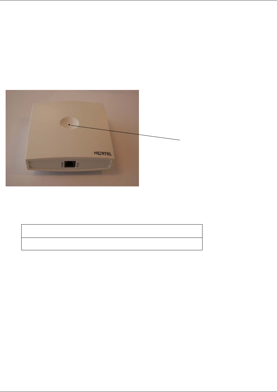
79 Chapter 4 Repeater installation
N0000623 01.5
Downloading firmware
In the event of new software releases it is possible to download new versions of the repeater
software. Refer to “Download Flash” on page 175 for information on firmware downloads to the
repeater.
Description of LED behavior on repeater
Figure 38
The repeater has one red LED for status indication. When the repeater is starting up the red LED
flashes, this process takes maximum two minutes. When the repeater is running the red LED lights
constantly.
Next step
To prepare handsets, go to Chapter 6.
To configure the DMC, go to Chapter 7.
Action required if LED not on or if the LED keeps flashing:
Check if repeater programming is correct.
Red LED
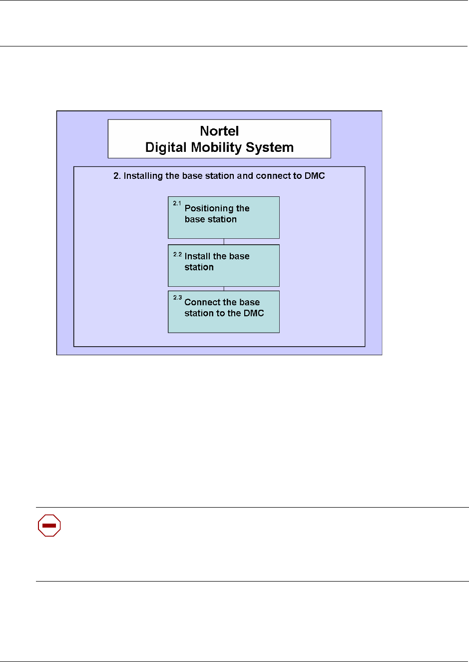
80
Chapter 5
Base station installation
This section describes the process for installing base stations.
Figure 39
Before you install portable equipment, ensure that a site planner defines the base station locations
and records the base station information in the host system programming record.
For more information about deployment, refer to the Digital Mobility Deployment Guide
accompanying the Deployment Kit.
This section includes the detailed information about:
•“Positioning a base station” on page 81
•“Installing the base stations” on page 81
Caution: You must install all base stations within 1500 meters (5,000 feet) of the DMC.
Always make a cable delay measurement to ensure seamless handover between base
stations. Refer to “Configuring the DMC through DMC OAM program” on page 101 or
“Configuring the DMC through the Master handset” on page 106 for more information
about cable delay measurement.
81
N0000623 01.5
Positioning a base station
Avoid installing base stations on large concrete or marble columns because these columns affect
radio coverage. If possible, place the base station a minimum of one meter (3 feet) from these
types of columns. Do not install a base station with the antenna housings near metal objects. Be
careful not to damage existing wiring or panels.
Do not position base stations in ducts, plenums, or hollow spaces used to transport environmental
air except where the duct, plenum or hollow space is created by a suspended ceiling having lay-in
panels.
To expand a coverage area with base stations, additional base stations must be placed in such a
way that overlap between the base stations radio coverage is established. It is recommended that
the overlap is at least 10 to 15 meters (30 to 50 feet).
Note: Radio coverage depends on material and construction of buildings and surroundings.
Installing the base stations
Install base stations on a wall.
Note: The base station must be placed in the right position. If the base station is placed
upside-down, the coverage area of the base station is decreased by 40 - 50%.
Note: Before beginning the installation, it is important to determine the location of the base
station for the best coverage. The coverage depends on the construction of the building,
architecture and choice of building materials. Refer to “Environmental checklist” on page 40 for
more information on environmental requirements for base stations.
This section provides information about:
•“Installing a base station” on page 82
•“Wiring the base station” on page 84
•“Description of LED behavior on base station” on page 86
Warning: Never install base stations in rows.
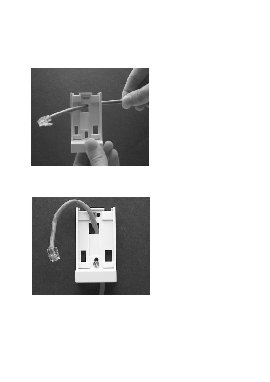
82
Installing a base station
1Use a twisted pair wire, Cat. 4 or 5, between the DMC and the base station with a RJ11
connector at the base station end of the wire. Connect the wire to the plug using the two inner
connectors of the plug. Pull the wire through the wall bracket.
Figure 40
2Mount the wall bracket on the wall using the screws accompanying the base station.
Figure 41
Note: Do not fasten the screws completely to allow for adjustments of the wire length when
connecting the wire to the base station.
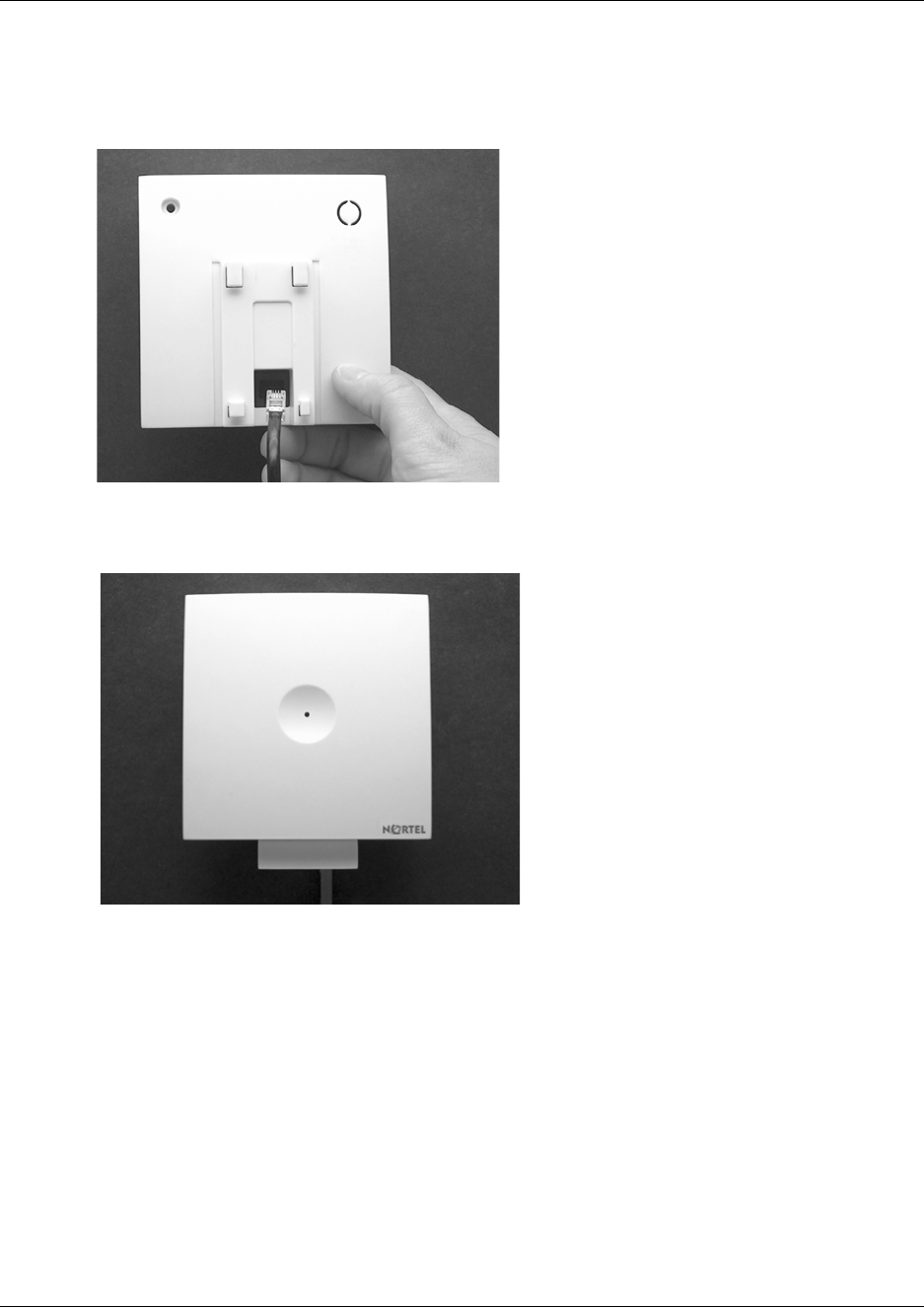
83
N0000623 01.5
3Connect the plug on the rear of the base station. Adjust the length of the wire, and then fasten
the wall bracket.
Figure 42
4Click the base station to the wall bracket.
Figure 43
5Connect the base station to the DMC. Refer to “Wiring the base station” on page 84 for more
information.
Note: If you need to remove the base station, separate it from the wall bracket with a gentle push
of a screwdriver inserted between the wall bracket and the base station.
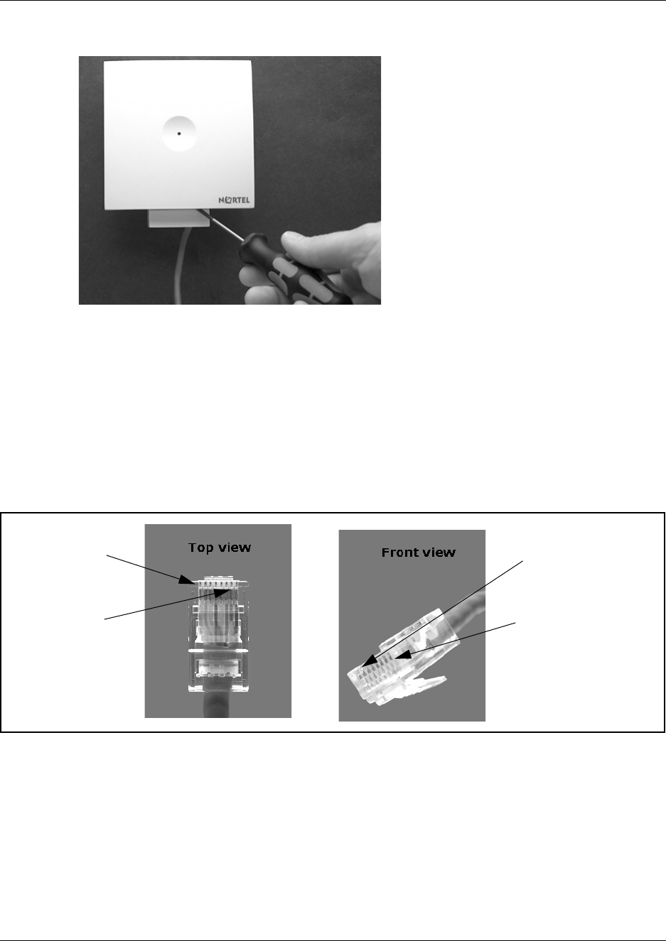
84
Figure 44
Wiring the base station
This section describes how to wire the base station to the DMC.
1Install the wires from the base stations to the DMC.
2Connect the base station wires to the RJ45 connector for the DMC. For placement of the
individual base station wires in the connector, see figures and table below.
Figure 45
Pin 1
Pin 8
Pin 8
Pin 1
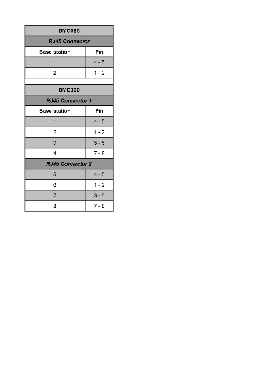
N0000623 01.5
Insert the RJ45 connector in the base station connection(s) of the DMC. Refer to “Description
of connectors and their placement” on page 33.
After wiring the base station the first time, you must measure the cable delay in order to
synchronize the base station. The synchronization ensures seamless handovers. For more
information about measuring cable delay, refer to “Configuring the DMC through DMC OAM
program” on page 101 or “Configuring the DMC through the Master handset” on page 106.
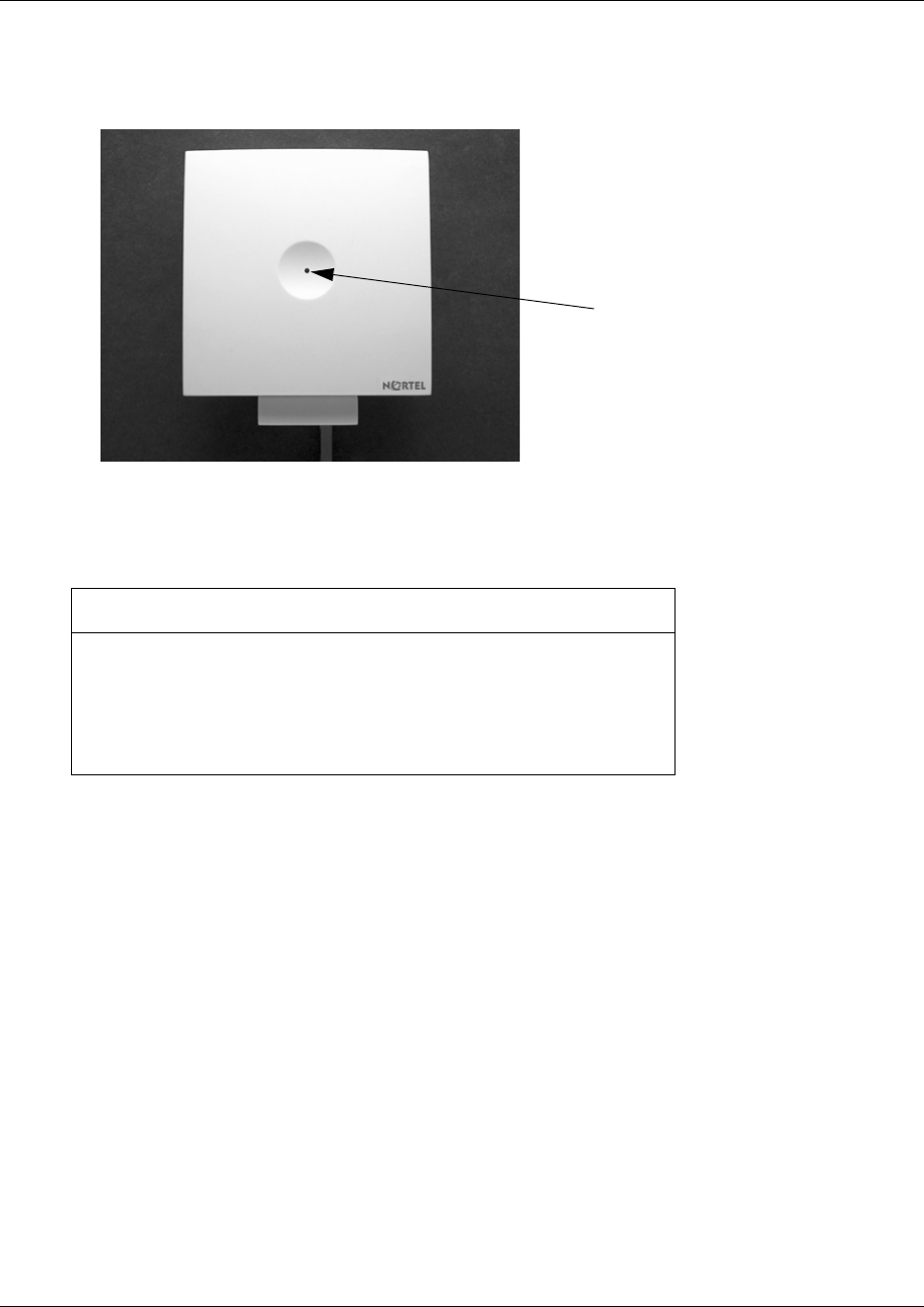
Description of LED behavior on base station
The base station has one red LED for status indication. When the base station is starting up the red
LED flashes, this process takes maximum two minutes. When the base station is running the red
LED lights constantly.
If repeaters are required, go to Chapter 4 (Repeater installation).
If no repeaters are required, go to either Chapter 7 (Configuring the DMC) or Chapter 6 (Preparing
handset for use).
Check if there is contact to the base station from the DMC, using the
RFP PCS command under Settings in the DMC OAM program.
Try connect another base station. If the other base station is not
working either, check the cable and the RJ45 connector for the
DMC.
Red LED

N0000623 01.5
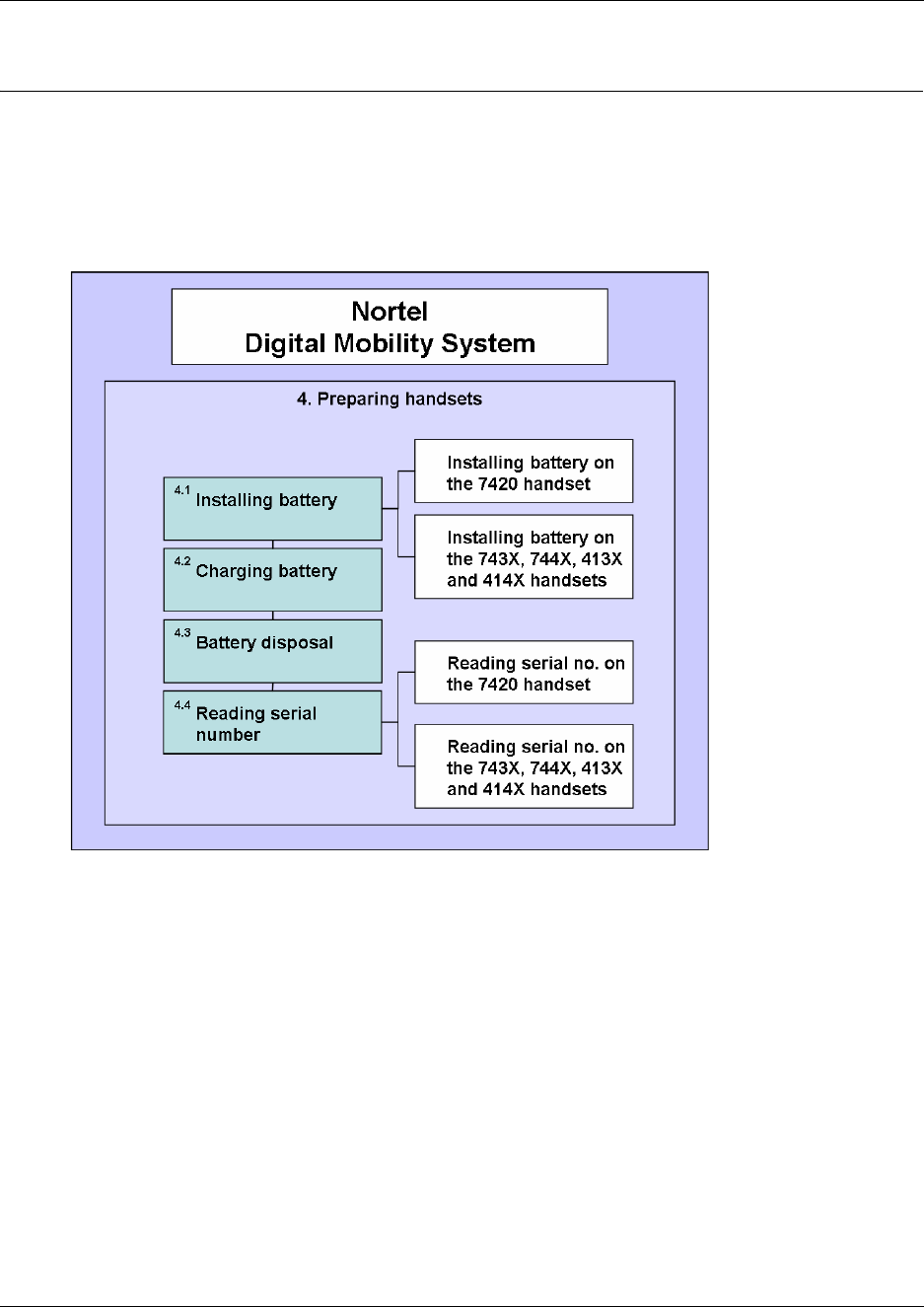
Chapter 6
Preparing handset for use
This section provides general safety information about handset and battery, information on how to
install and charge the battery and how to read the serial numbers on the different handsets. It also
contains a short description of the handset and handset keys.
Figure 47
This section provides information about:
•“Handset information” on page 89
•“Battery information” on page 89
•“Installing battery on 7420 handsets” on page 90
•“Installing battery on 413X, 414X, 743X, and 744X handsets” on page 91
•“Charging battery” on page 92
•“Battery disposal” on page 92
•“Reading serial number” on page 93

89
N0000623 01.5
Handset information
Read the following information before you use the handset.
Ensure that the adapter voltage is the same as the electrical outlet voltage. The 41XX/74XX
handset uses radio signals and does not guarantee a connection in all circumstances. Do not rely on
a cordless handset to make emergency calls.
Never use your handset:
• in the vicinity of electrical detonators
• in shielded rooms
• in areas where radio transmission is forbidden
• in aircraft
Do not place a handset near:
• water, moisture or damp areas
• heat sources, direct sunlight or unventilated areas
• devices which generate strong magnetic fields such as electrical appliances, fluorescent lamps,
computers, radios, televisions or fax machines
• areas where the handset can be covered, its ventilation impaired, liquid spilled on the unit or
objects inserted into the handset through any openings.
• areas with dust, vibration, shock or temperature extremes
Check for small metal objects in the handset earpiece/mouthpiece before using the handset.
Do not store or locate flammable liquids, gases, or explosive materials in the same compartment or
vicinity as the cordless handset, its parts or accessories.
Battery information
Read the following information before you handle the batteries:
• Do not replace the batteries in potentially explosive environments, such as rooms where
flammable liquids or gases are present.
• The battery will explode if disposed of in a fire.
• Do not charge the batteries unless you use the Nortel approved charger and the proper
batteries.
• Only use battery type NT7B65LD in the 41XX/74XX handset. Do not use these batteries with
other products. These batteries were designed specifically for use with the 41XX/74XX
handset and the 41XX/74XX charger ONLY. Improper use of the batteries may result in fire
hazard.
• Do not do anything that would cause the battery to short circuit.
Do not let the battery or the charger come into contact with conductive metal objects.
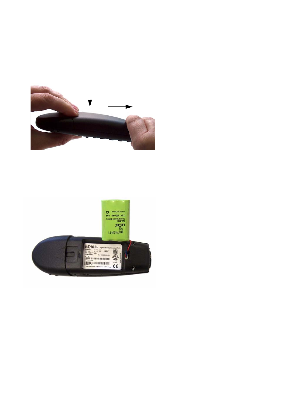
90
Installing battery on 7420 handsets
Note: The battery is connected to the handset when it is shipped from the factory.
1To change the battery press down the back cover and push it 5 mm (1/5 inch) towards the
headset plug.
Figure 48
2Lift off back cover.
3Place the battery plug in the slot in the battery box.
Figure 49
4Insert battery with the label readable.
5Replace the back cover.
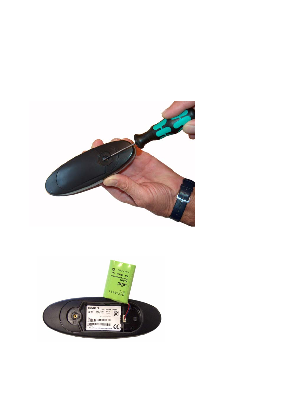
91
N0000623 01.5
Installing battery on 413X, 414X, 743X, and 744X handsets
Note: The battery is connected to the handset when it is shipped from the factory.
1To change the battery unscrew the plate on the rear of the handset to access the battery
compartment. Use a normal screw driver.
2Insert the screwdriver into the small crack behind the blind cover and break to open the
handset.
Figure 50
3Place the battery plug in the slot in the battery box.
Figure 51
4Insert battery with the label readable.
5Replace the back cover.

92
Charging battery
When charging the battery for the first time, it is necessary to leave the handset in the charger for
14 - 16 hours before the battery is fully charged and the handset ready for use.
Note: During normal operation, it takes approximately 3.5 hours to charge the handset from fully
discharged to its full capacity.
• Place the handset in the charger.
For correct charging, be sure the room temperature is between 0°C and 25°C (32°F and 77°F).
Do not place the handset in direct sunlight. The battery has a built-in heat sensor which will
stop charging if the battery temperature is too high.
If the handset is turned off when placed in charger, only the LED indicates the charging. When
handset is turned off, the LED flashes at a low frequency while charging and lights constantly
when the charging is finished. There will be no reaction for incoming calls.
If the handset is turned on when charging, the display shows the charging status. The display
goes back to normal mode when fully charged. It will not vibrate. Auto-answer is inactive. The
handset reacts normally for incoming calls.
It is necessary to recharge the battery when the display shows BATTERY LOW, or if the handset
cannot be turned on. When the battery is fully discharged, up to 10 minutes may pass before
charging begins (display lights up). When the charger begins the charging, status is shown on the
display if the handset is turned on.
Battery disposal
Warning: Nickel metal hydride batteries must be disposed of in the correct manner. Do not
dispose of the batteries in office or household waste.
Nickel metal hydride batteries are recyclable. You can help preserve the environment by returning
your unwanted batteries to your nearest recycling center for recycling or proper disposal.
Contact your system administrator for more information about battery disposal and recycling
centers in your local area.
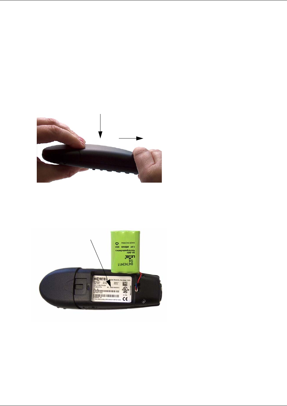
Chapter 6 Preparing handset for use
N0000623 01.5
Reading serial number
The serial number of the handset can be found either on the label behind the battery or by pressing
*99984*3/OK on the handset to be registered. Pressing *99984*3OK on the handset the serial
number is shown in the display.
Reading serial number on 7420 handsets
1Press down the back cover and push it 5 mm (1/5 inch) towards the headset plug.
Figure 52
2Lift off back cover.
3Lift the battery and read the serial number.
Figure 53
4Replace battery and back cover.
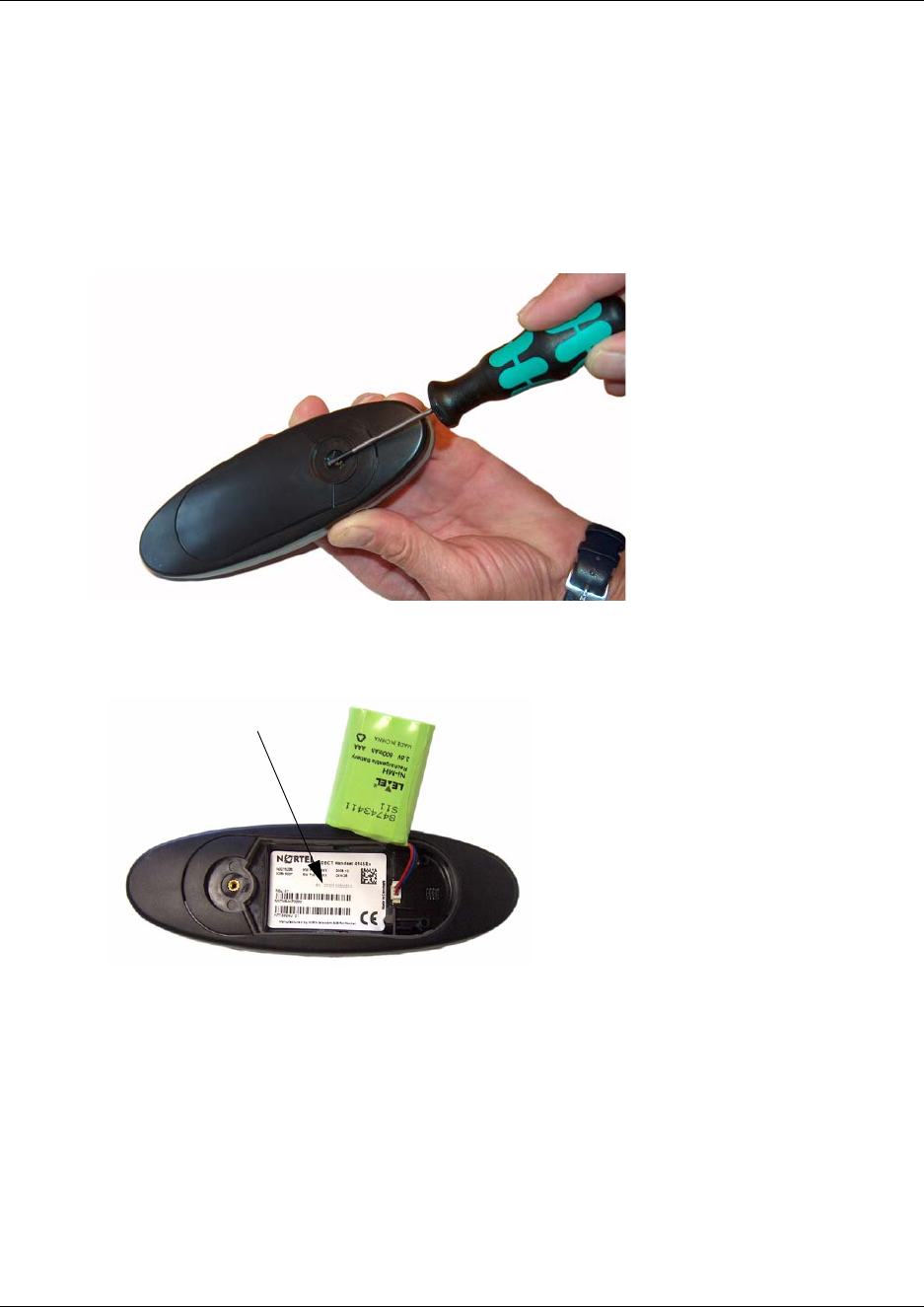
94
Reading serial number on 413X, 414X, 743X, and 744X handsets
1Use a screwdriver to unscrew the plate on the rear of the handset to access the battery
compartment.
2Insert the screwdriver into the small crack behind the blind cover and press to open the
handset.
Figure 54
3Lift the battery and read the serial number.
Figure 55
4Replace battery and back cover.
Note: Alternatively, you can also press *99984*3OK on the handset to be registered. The serial
number is now shown in the display.
Next step
To configure the DMC, go to Chapter 7.
To register and subscribe handsets, go to Chapter 8.

95
N0000623 01.5
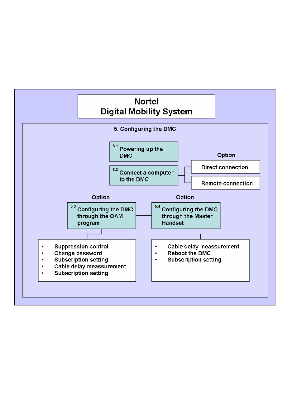
96
Chapter 7
Configuring the DMC
This section provides you with information on how to power up the DMC, connect a computer to
the DMC and how to configure the DMC through the DMC OAM Program and the Master
handset.
Figure 56
This section includes information about:
•“Powering up the DMC” on page 97
•“Connecting a computer to the DMC” on page 97
•“Configuring the DMC through DMC OAM program” on page 101
•“Configuring the DMC through the Master handset” on page 106
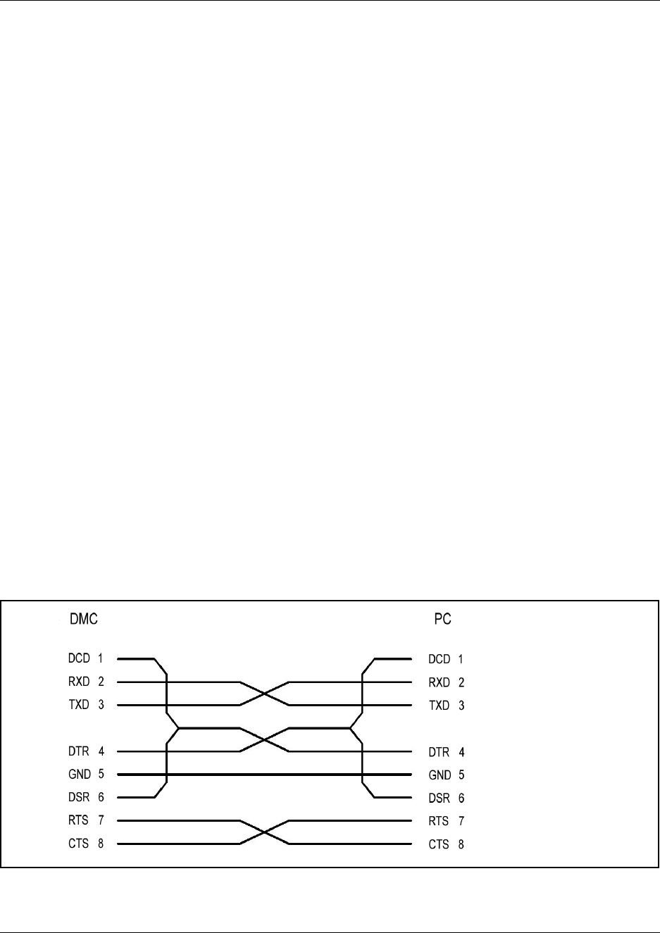
97
N0000623 01.5
Powering up the DMC
After installing the DMC you need to power up the DMC:
1Insert the adapter accompanying the DMC in the power supply of the DMC. Refer to
“Description of connectors and their placement” on page 33.
2Connect the adapter to the main power source.
3The DMC is now powered up and you can connect a computer to the DMC.
Connecting a computer to the DMC
To use the DMC OAM program you need to connect a computer to the DMC.
Note: In a linked system always connect the computer to the Primary DMC.
You can connect a computer to the DMC in the following ways:
• Direct connection (serial connection) using a null-modem cable
• Remote connection using a serial-IP converter or a modem
Direct connection (serial connection) using a null-modem cable
The serial port of the DMC is a 9-pin DSUB male connector for direct connection between the
computer and DMC. When connecting a computer to the DMC in a serial connection, use a
null-modem cable. Refer to “Description of connectors and their placement” on page 33.
Note: The maximum length of the null-modem cable must not exceed five meters (16 feet).
Figure 57
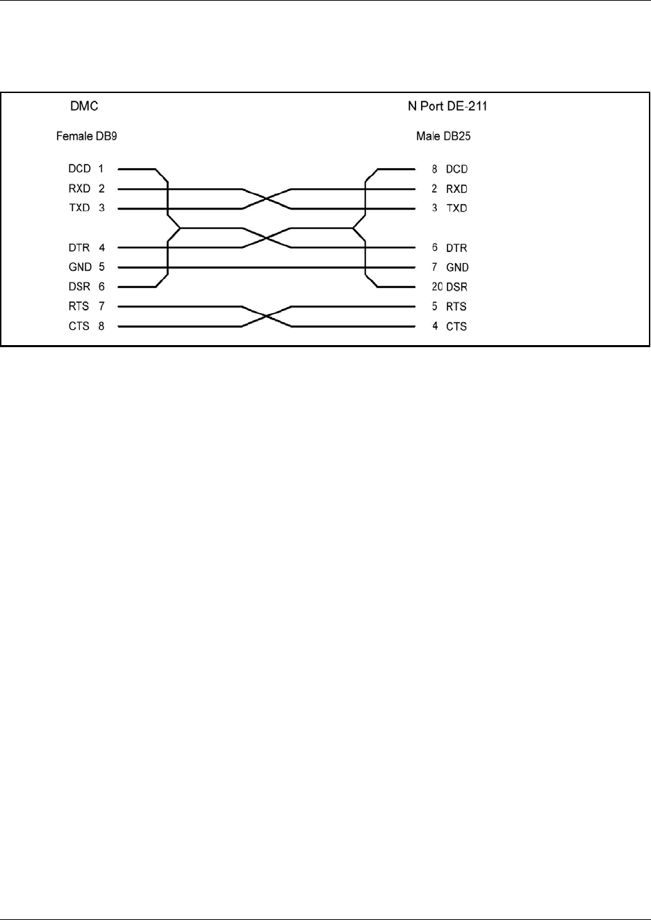
98
Remote connection using a serial-IP converter or a modem
Figure 58
Serial-IP converter
The serial port of the DMC is a 9-pin DSUB male connector and can be used with an RS232
serial-IP converter for remote access to the DMC. Use a null-modem cable between the DMC and
the serial-IP converter.
Note: The maximum length of the null-modem cable must not exceed five meters (16 feet).
Note: Nortel recommends the use of the serial-IP converter from MOXA model DE-211.
How to use the serial-IP converter from MOXA model DE-211
1Put all dip switches to OFF position.
2Obtain or make an IP modem cable (see Figure 58).
Note: Nortel recommends to buy the cable NP21101 from MOXA.
3Power up the NPort DE-211.
4Install the MOXA software on your computer.
5Configure the NPort DE-211 to program the IP address and adjust the serial parameters to be
compatible with the ones outlined in Table 14.
6Associate a virtual Com port to the NPort DE-211.
7Start the DMC OAM program and select the virtual Com port of the NPort DE-211.
Note: For more detailed information, refer to the hardware and software installation guide
supplied by MOXA for correct installation and configuration of the NPort DE-211.
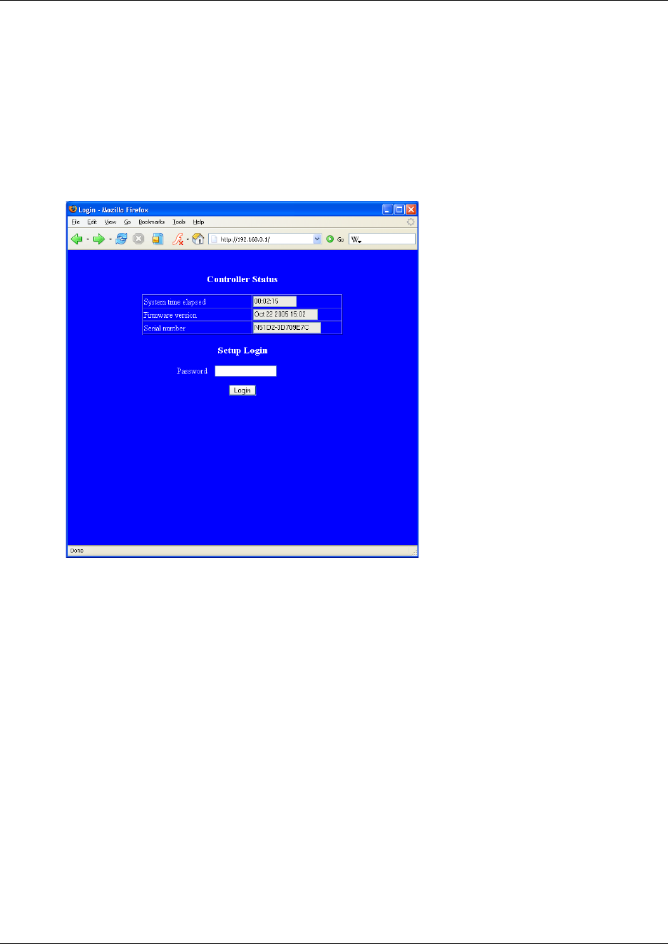
99
N0000623 01.5
How to use the serial-IP converter LanConn-100
1Connect the LanConn-100 to the computer using a crossed cable (LAN Patch Cable).
2Set the computer’s IP to 192.168.0.2
3Open a browser and type 192.68.0.1 in the address field.
The following browser Login Page appears.
Figure 59
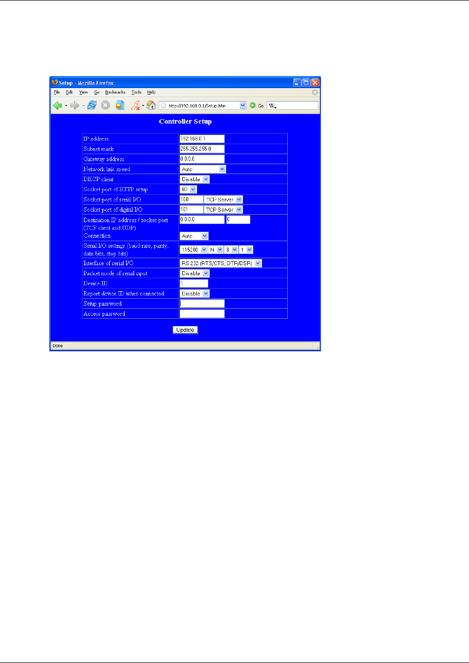
100
4Click Login.
The following browser Setup Page appears.
Figure 60
5Change the IP adress, Subnet mask, Gateway address, etc. to the appropriate values.
6Serial I/0 settings (baud rate, pocket panty, data bits, stop bits) must be set to 115200, N, 8, 1.
7Interface of Serial I/0 must be set to RS 232 (RTS/CTS, DTR,DSR).
8Connect the LanConn-100 to the DMC using a null-modem cable.
9Start the DMC OAM program and select the wanted Telnet communication configuration.
Note: For more detailed information, refer to the installation guide supplied by Eletech.

101
N0000623 01.5
Modem
The serial port of the DMC is a 9-pin DSUB male connector and can be used with an RS232 cable
for remote access to the DMC through a standard modem.
Before connecting the modem to the DMC, ensure that the modem has been configured for the
following default Com port settings of the DMC:
Configuring the DMC through DMC OAM program
From the DMC OAM program it is possible to configure the DMC on following parameters that
are useful when setting up the system.
Note: In a linked system all configuration is carried out on the Primary DMC.
Note: Configuring the DMC requires the use of the DMC OAM program. A Hyper terminal
session with the DMC is not possible.
For more information about installing and opening the DMC OAM program, refer to “Installing
DMC OAM and Digital Mobility Service Tool” on page 44.
Table 14
115200 bit/sec.
Data bit: 8
Parity: None
Stop bit: 1
Flow control: Hardware:
DCD, DSR, DTR,
CTS, RTS
Parameter: Action:
Change password When starting the DMC OAM program you will be prompted a password.
The default password is: . It is recommended to change this
password at the earliest opportunity.
Suppression Control If necessary, you can change the suppression level to make the handsets
function better in different noisy environments.
Subscription The subscription setting must be set to Allow Subscription
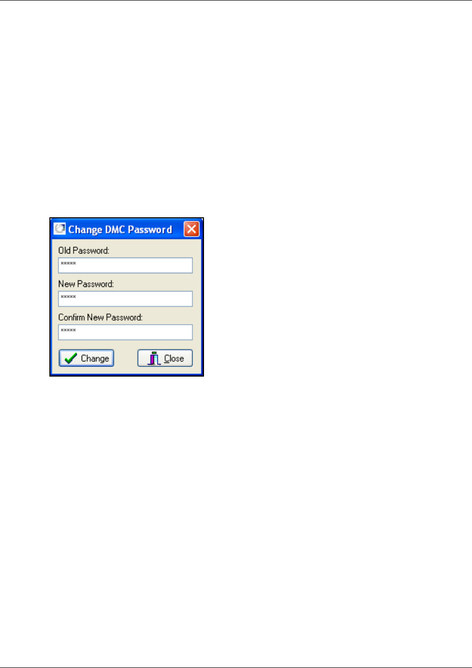
102
This section provides information about
•“Change password” on page 102
•“Suppression control” on page 103
•“Subscription setting” on page 104
•“Cable Delay Measurement” on page 105
Change password
1On the Settings menu, click Change Password.
A Change DMC Password dialog box appears.
Figure 61
2Type your old password in the Old Password field.
3Type the new password in the New Password field.
Maximum length of a password is 15 characters.
4Type the new password again in the Confirm New Password field.
5Click Change.
The password used when starting the DMC OAM program has now been changed.
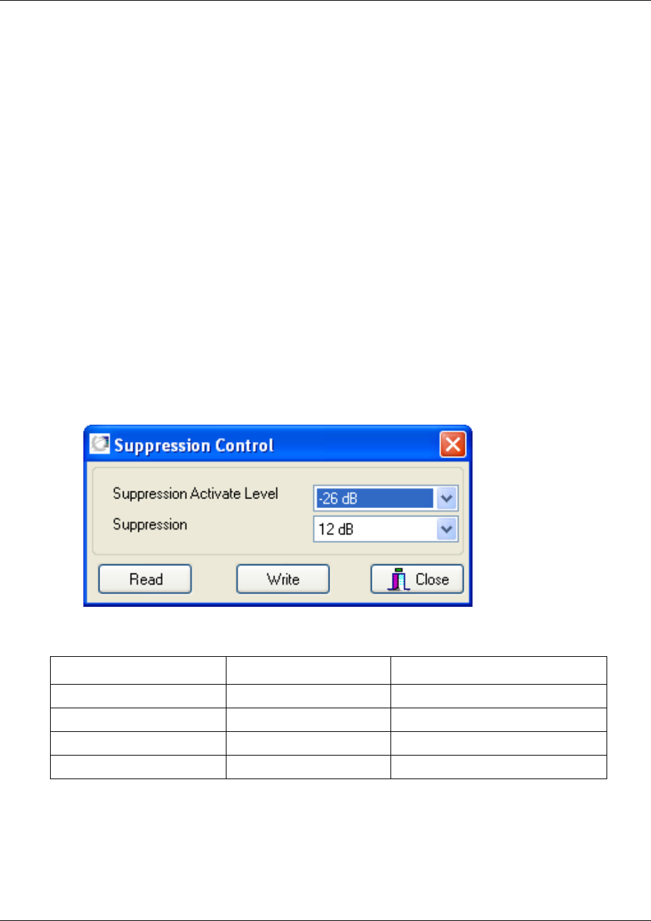
103
N0000623 01.5
Suppression control
Using the Suppression Control command makes the handsets function better in different noisy
environments.
Note that this setting is only available through the DMC OAM program. The Master handset
cannot provide this information.
The purpose of the suppressor is to suppress an echo which is not fully suppressed by the built-in
echo canceller. The suppressor makes the connection effectively simplex, forcing the speakers not
to interrupt one another.
Caution: Only use the Suppression Control command if performance of the built-in echo
canceller is insufficient. Only tune and test the parameters with great care to minimize undesirable
side effects such as distorted or fluctuating audio.
1On the Settings menu, click Suppression Control.
A Suppression Control dialog box appears, showing the current suppression control values.
Note: You can also click Read to display the current suppression control values in the DMC.
Figure 62
Suppression with 6 dB decreases the volume by 50 per cent.
Suppression with 9 dB decreases the volume by 65 per cent.
Suppression with 12 dB decreases the volume by 75 per cent.
Suppression with 15 dB decreases the volume by 82 per cent.
Table 15
Suppression Activate Level Suppression Used in

104
2Select a value from the Suppression Activate Level list.
The Suppression Activate Level is the level at which the suppression is to be activated.
3Select a value from the Suppression list.
Suppression is the number of decibels (dB) the sound is suppressed, when activated.
4Click Write to write the new settings to the DMC.
5Click Close to close the dialog box.
Subscription setting
When powering up the DMC, subscription mode is active for 10 minutes. If more time is needed:
• Select the Allow Subscription check box in the Registration tab. This will keep subscription
mode active until the Allow Subscription check box is deselected.
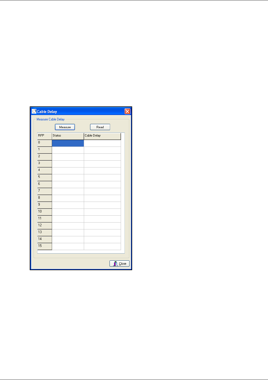
105
N0000623 01.5
Cable Delay Measurement
The Measure Cable Delay command is used to measure the delay from the DMC to the base
stations (RFPs).
Note: The delay must be measured the first time after a base station has been connected in order
to synchronize the base station. The synchronization ensures seamless handovers.
1On the Settings menu, click Measure Cable Delay.
A Cable Delay dialog box appears.
Figure 63
Status shows whether the base station (RFP) is running or not.
2Click Read to acquire the data from the DMC.
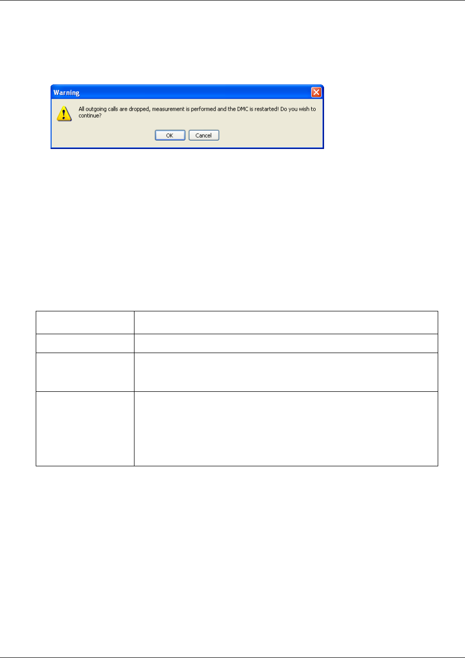
106
3Click Measure to make the DMC measure the delay (measurement can take a few minutes).
A warning message appears.
Figure 64
4Click OK to continue.
Note: When restarting after a cable delay measurement, reliable system performance will be
achieved after a couple of minutes.
5Click Close to close the dialog box.
Configuring the DMC through the Master handset
From the Master handset it is possible to configure the DMC on a few parameters that are useful
when setting up the system. The parameters are:
Note: For suppression control you need to use the DMC OAM program, see “Configuring the
DMC through DMC OAM program” on page 101.
For more detailed information on the Master handset, see “Configuring the DMC” on page 96.
This section provides information about
•“Restart the DMC” on page 107
•“Subscription setting” on page 107
•“Cable delay measurement” on page 108
Parameter: Action:
Allow Subscription
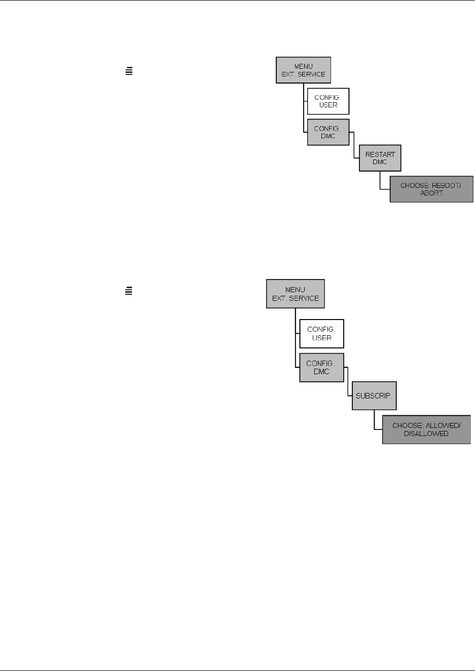
107
N0000623 01.5
Restart the DMC
Figure 65
1Press MENU ( ) - go to EXT. SERVICE.
2Press 3/OK - go to CONFIG. DMC.
3Press 3OK - go to RESTART DMC.
4Press 3OK.
Select REBOOT to confirm or ABORT to exit
the rebooting process.
Press 3/- to confirm your selection. The
system will reboot if REBOOT has been
selected.
Subscription setting
Master handset: subscription
Press MENU ( ) - go to EXT. SERVICE.
Press 3/- go to CONFIG. DMC.
Press 3/- go to SUBSCRIP.
Select ALLOWED to allow handset to be
subscribed to the system. Select
DISALLOWED to prevent handsets from
being subscribed.
Press 3/- to confirm your selection.
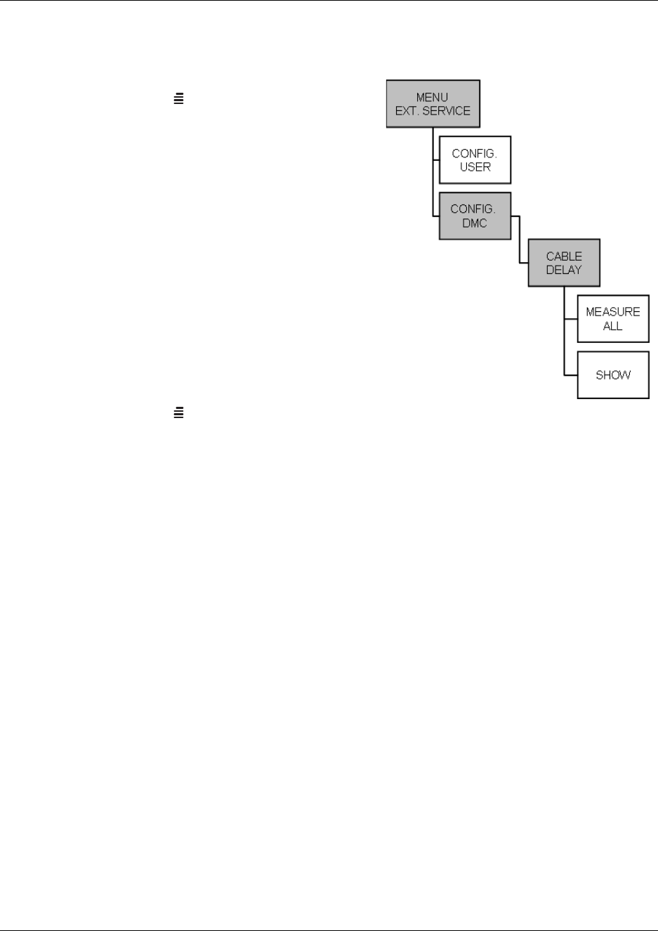
Chapter 7 Configuring the DMC
Digital Mobility System Installation and Configuration Guide
Cable delay measurement
Master handset: cable delay
Press MENU ( ) - go to EXT. SERVICE.
Press 3/- go to CONFIG. DMC.
Press 3/- go to CABLE DELAY.
Press 3/- go to MEASURE ALL.
Press 3/.
Note: The system is rebooted and all calls are
dropped.
Note: When restarting after a cable delay
measurement, reliable system performance will
be achieved after a couple of minutes.
To view the cable delay of an individual
base station
Press MENU ( ) - go to EXT. SERVICE.
Press 3/- go to CONFIG. DMC.
Press 3/- go to CABLE DELAY.
Press 3/- go to SHOW.
Press 3/.
The cable delays for each base station is visible in the display. Use the < > keys to view the
cable delay for each base station.
To register and subscribe handsets, go to Chapter 8.

Chapter 7 Configuring the DMC
N0000623 01.5
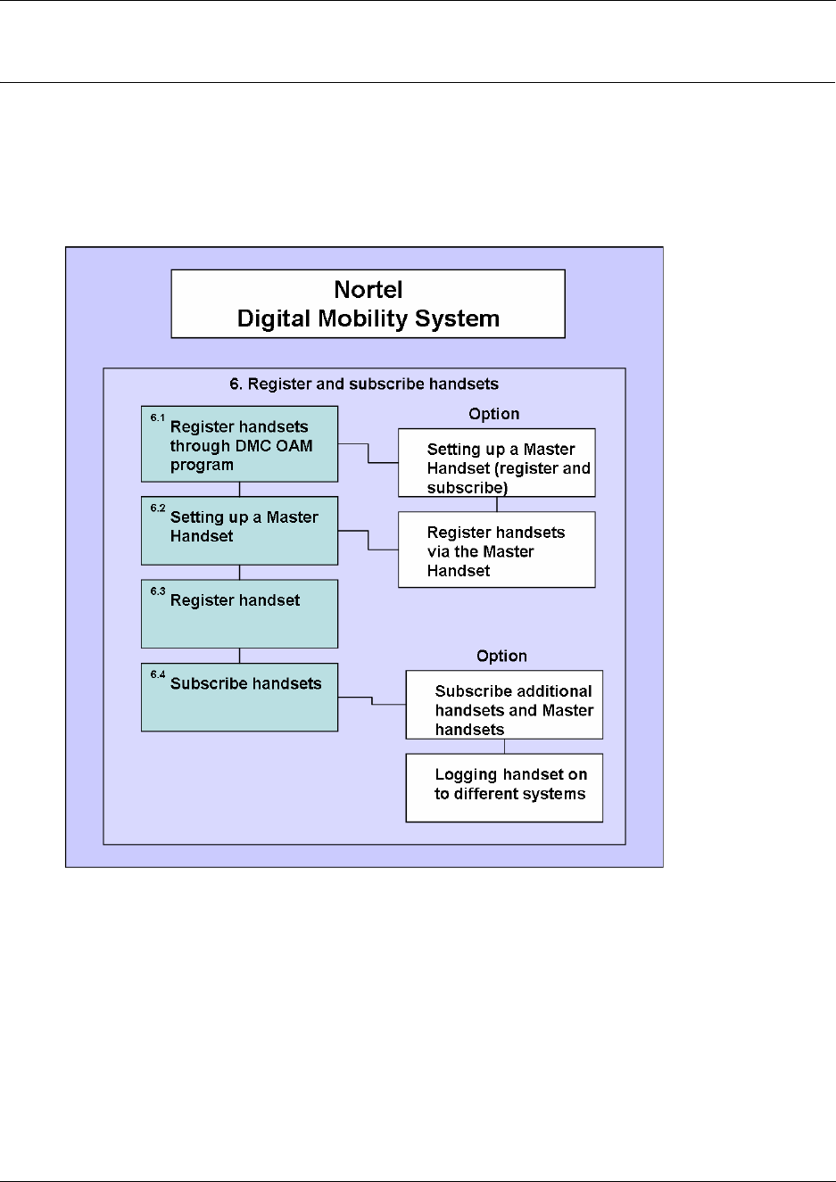
Digital Mobility System Installation and Configuration Guide
Chapter 8
Handset registration and subscription
This section provides you with information about handset registration and subscription. You must
register and subscribe a handset before you can use it. The section also contains information about
host system features and host system and handset interoperability.
Figure 68
This section includes information about:
•“Register handsets through DMC OAM program” on page 111
•“Register handsets through Master handset” on page 114
•“Subscribe handsets” on page 118
•“Host system and handset interoperability” on page 120
When registering handsets you enter information about the handset settings (such as; the handset
serial number, name, directory number etc.) in the system database. When subscribing handsets
you subscribe a registered handset to the system for usage. If the handset is not registered in the
system database, subscription of the handset is not possible.
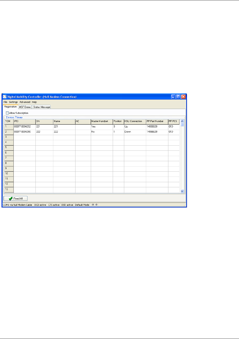
111
N0000623 01.5
Register handsets through DMC OAM program
This section provides information about:
•“Setting up a Master handset” on page 112
•“Registering handsets” on page 113
When a connection between a DMC and the system is established, the DMC OAM program
displays all the information for registering handsets. Subscription data is read and shown in the
Registration tab screen.
Figure 69
Variable Description
Digital loop identifier (from the DMC)
IPEI International Portable Equipment Identity (the serial number of
the handset)
Directory No The directory number (DN) of the handset
Name The name of the handset
AC Authentication Code (an optional code that can be used when
subscribing handset to DMC)
Master Handset The special rights for the handset
Position Position in database
KSU Connection Host system connection status
PP Part Number The part number of the handset (read by DMC)
PP PCS The PCS of the handset (read by DMC)
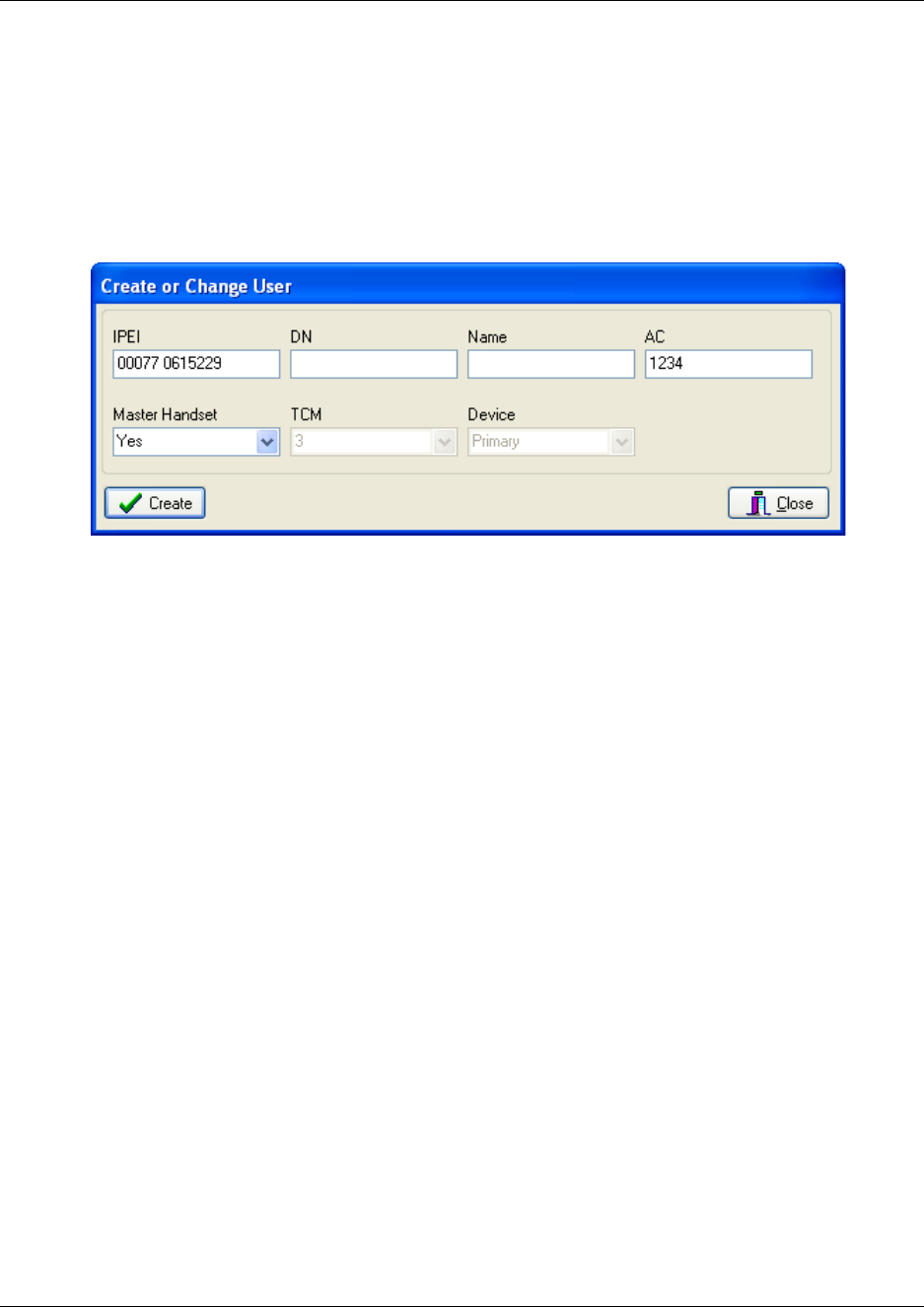
Chapter 8 Handset registration and subscription
Digital Mobility System Installation and Configuration Guide
Setting up a Master handset
In the Registration tab, click Read All to display all registered users on the DMC.
Alternate-click on an empty row, and then click Create.
A Create or Change User dialog box appears.
DMC OAM: create or change user record
In the IPEI field, type the serial number of the handset.
This is found either on a label under the battery, on the packaging label, or by pressing
*99984*3/the handset to be registered. The serial number consists of a five-digit handset
type (manufacturer code) and then a seven-digit handset number, separated by a space.
Refer to “Installation prerequisites” on page 43.
DN field: Read only. The DN of the handset is given by the host system after the handset has
been subscribed to the system.
Name field: Read only. The name of the handset is given by the host system after the handset
has been subscribed to the system.
In the AC field, type the authentication code (optional).
The authentication code is a subscription password of a maximum eight digits, defined by the
technicians, and can be used when connecting the handset to the DMC. The AC is a
subscription pin code for the individual handset.
Refer to “Installation prerequisites” on page 43.
From the Master Handset list, select Yes.
Click Create to register the Master handset.
A confirmation message appears when the handset is registered.
Repeat steps 1 to 8 for each new Master handset to be registered to the system.
From the Main window, select the Allow Subscription check box. If not selected, subscription
mode is only active for 10 minutes after the DMC has been powered up.
Note: As a security measure, subscription mode must be disabled when the DMC OAM
program is closed.
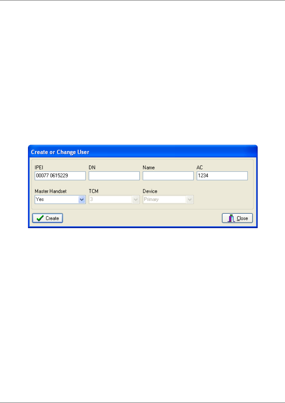
Chapter 8 Handset registration and subscription
N0000623 01.5
Once the Master handset details have been entered into the registration screen of the DMC
OAM program, the Master handset can be subscribed to the system.
For more information about subscription of handsets, see “Subscribe handsets” on page 118.
Registering handsets
Refer to “Configuring the DMC through DMC OAM program” on page 101 for information about
allowing subscription.
In the Registration tab, click Read All to display all registered users on the DMC.
Alternate-click on an empty row, and then click Create.
A Create or Change User dialog box appears.
DMC OAM: create or change user record
In the IPEI field, type the serial number of the handset.
This is found either on a label under the battery, on the packaging label or by pressing
*99984*3/the handset to be registered. The serial number consists of a 5-digit handset
type (manufacturer code) and then a 7-digit handset number separated by a space.
Refer to “Installation prerequisites” on page 43.
DN field: Read only. The DN of the handset is given by the host system after the handset has
been subscribed to the system.
Name field: Read only. The name of the handset is given by the host system after the handset
has been subscribed to the system.

Chapter 8 Handset registration and subscription
Digital Mobility System Installation and Configuration Guide
In the AC field, type the authentication code (optional).
The authentication code is a subscription password of max. eight digits, defined by the
technicians, and can be used when connecting the handset to the DMC. The AC is a
subscription pin code for the individual handset.
Refer to “Installation prerequisites” on page 43.
From the Master Handset list, select No.
Click Create to register the handset.
A confirmation message appears when the handset is registered.
Repeat steps 1 to 8 for each new handset to be registered to the system.
From the Main window, select the Allow Subscription check box. If not selected, subscription
mode is only active for 10 minutes after the DMC control unit has been powered up.
Once the handset details have been entered into the registration screen of the DMC OAM
program, the handset can be subscribed to the system. Subscription of handsets requires the
use of each registered handset and is not to be handled through the DMC OAM program.
For more information about subscription of handsets, see “Subscribe handsets” on page 118.
This section provides information about:
•“Setting up a Master handset (registering and subscribing)” on page 114
•“Registration of additional handsets” on page 115
Before subscription of the master handset and the following registration of the individual
handsets, make sure that the handsets have been fully charged prior to the registration process.
When charging the battery for the first time it is necessary to leave the handsets in the charger for
14 - 16 hours in order to secure full charging.
Setting up a Master handset (registering and subscribing)
Before registering a Master handset, you need to power up the DMC. Refer to “Powering up
the DMC” on page 97.
When powering up the DMC, the system automatically enters into subscription mode for 10
minutes. This is the time that is available to subscribe the first handset which automatically
becomes the Master handset.
Registration of the first handset - the Master handset - is done automatically when
subscribing the handset to the system.
Power up the handset by pressing the HOOK-key ( ).
Press MENU ( ).
Press < - go to MENU LOGIN

Chapter 8 Handset registration and subscription
N0000623 01.5
Press 3/.
Press > - go to SUBSCRIPTION CREATE.
Press 3/ . The handset will now search for the serial number of the system.
As soon as the right serial number of the system appears in the display press 3/ . (The
serial number is indicated on the label on the rear of the DMC).
Refer to “Installation prerequisites” on page 43.
CREATE SYSTEM 1 AC: _________ (Authentication Code is optional)
Choose system no. - press 3/.
An antenna symbol will appear in the display to indicate a successful subscription.
The handset has now become the Master handset for the system and will be placed on TCM
loop no. 1.
Refer to “Installation prerequisites” on page 43.
It is possible to have more than one Master handset. Registration and subscription of
additional Master handsets through a Master handset follows the same procedure as for registering
additional handsets and subscribing handsets, which is described in the next section. This means
that an additional Master handset is not registered automatically when subscribing it to the system.
Registration of additional handsets
Before registering additional handsets can take place, the handsets are assigned to the host system
to configure the DN record for each handset. Note that each DN relates directly to one TCM port
on the host system, which, in turn, relates directly to a TCM port on the DMC. For more
information about host systems, see “Host system and handset interoperability” on page 120.
The Master handset can add additional handsets to the system using two methods, depending on
the registration scenario:
• when the system is being set up and additional handsets are being registered for the first time
• after system setup and additional handset are being added, either by filling free capacity, or by
linking another DMC to increase system capacity
First time registration of additional handsets through the Master handset
Press MENU () - go to EXT. SERVICE. (See illustration of menu structure on the next
page).
Press 3/- go to CONFIG. USER.
Press 3/- go to ADD.
Press 3/- go to ENTER POS.
Press 3/- enter the position of additional handsets.
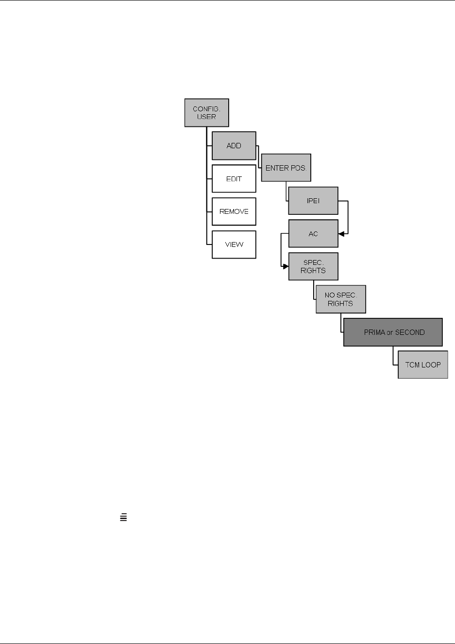
Chapter 8 Handset registration and subscription
Digital Mobility System Installation and Configuration Guide
Press 3/- IPEI appears in the display. Type the serial number of the handset. The IPEI
serial number is found on the label behind the battery pack.
Alternatively, press *99984*3/on the handset to be registered. The serial number is now
shown in the display.
Master handset: register handsets
Note: The serial number
has to be entered as
continuous numbers.
Refer to “Installation
prerequisites” on page 43.
Press 3/- AC appears
in the display. Type an
authentication code (max.
eight digits)
(AC is optional). Refer to
“Installation prerequisites”
on page 43.
Press 3/- SPEC.
RIGHTS appears in the
display. Special rights are
only given to additional
Master handsets. Select No
SPEC. RIGHTS.
Press 3/- Select
PRIMA or SECOND.
Secondary is only an option
if the handset is being registered on a linked system. In a linked system there is a Primary
DMC and a Secondary DMC.
Press 3/- TCM LOOP appears in the display. Type the TCM loop number of the chosen
Primary or Secondary DMC, and then press 3/. Refer to “Installation prerequisites” on
page 43.
A SUCC. message appears in the display.
To register another handset, press 3/and repeat steps 2 to 10.
Press MENU ( ) to exit.
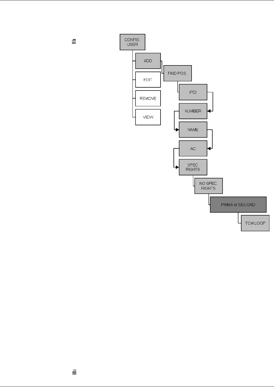
Chapter 8 Handset registration and subscription
N0000623 01.5
Registering handsets to existing system through Master handset
Master handset: register handsets to existing system
Press MENU () - go to EXT.
SERVICE. (See illustration of
menu structure on the next
page).
Press 3/- go to CONFIG.
USER.
Press 3/- go to ADD.
Press 3/- go to FIND POS.
All the systems positions and
directory numbers can now be
displayed using the < > keys.
Find the wanted positions.
Press 3/- IPEI appears in
the display. Type the serial
number of the handset.
• The IPEI serial number is
found on the label behind
the battery pack.
• Alternatively, press
*99984*3/OK on the
handset to be registered.
The serial number is now
shown in the display.
Note: The serial number has to
be entered as continuous numbers.
Refer to “Installation prerequisites” on page 43.
Press 3/- AC appears in the display. Type an authentication code (max. eight digits). (AC
is optional). Refer to “Installation prerequisites” on page 43.
Press 3/- SPEC. RIGHTS appears in the display. Special rights are only given to
additional Master handsets. Select NO SPEC. RIGHTS.
Press 3/- Select PRIMA or SECOND. Secondary is only an option if the handset is being
registered on a linked system.
Press 3/- TCM LOOP appears in the display. Type the TCM loop no. of the chosen
Primary/Secondary DMC, and then press 3/. Refer to “Installation prerequisites” on page
43.
A SUCC. message appears in the display.
To register another handset, press 3/and repeat steps 2 to 10.
Press MENU ( ) to exit.

Chapter 8 Handset registration and subscription
Digital Mobility System Installation and Configuration Guide
Subscribe handsets
This section provides information about:
•“Subscribing additional handsets and additional Master handsets” on page 118
•“Subscribing a handset to different systems” on page 119
Note: Subscription of handsets requires the use of each registered handset.
Note: To make subscriptions, the system must allow subscriptions to be made. Some systems also
require an Authentication Code (AC). If more than one system currently permits subscription, you
will need to know the ID of the system (ARI code) to which you wish to subscribe. Authentication
Codes and system ID’s (ARI codes) will be provided by the system administrator.
Refer to “Installation prerequisites” on page 43 for information about Authentication Codes.
Before subscribing handsets you need to ensure:
• that handset battery has been charged (“Preparing handset for use” on page 88)
• that the handsets have been registered to the system (“Register handsets through DMC OAM
program” on page 111 or “Register handsets through Master handset” on page 114)
• that subscription is allowed (“Configuring the DMC through DMC OAM program” on page
101)
Subscribing additional handsets and additional Master handsets
1Press MENU ( ) - go to MENU LOGIN.
2Press 3/OK - go to SUBSCRIPTION CREATE to subscribe to a system.
3Press 3/OK. The handset searches for the serial number of the system.
4Use the < > keys to scroll between the IDs systems if there is more than one system available.
During subscription, the handset searches for free positions and performs subscription on the
first free position.
5As soon as the correct serial number of the system appears in the display, press 3/OK.
The serial number is located on the label on the rear of the DMC.
6Enter the AC (if required) using the keyboard, and press 3/OK.
An antenna symbol appears on the display to indicate a successful subscription. If not, the
subscription has failed and the procedure must be retried.

119 Chapter 8 Handset registration and subscription
N0000623 01.5
Subscribing a handset to different systems
The handset can be subscribed (connected) to a maximum of 10 different systems.
Note: To be able to log on to a system, subscription to the system must be established.
Changing to another system automatically
Note: Auto login should only be used when systems are separate, with no overlaps.
1Press MENU ( ) - go to MENU LOGIN.
2Press 3/OK - go to SELECT LOGIN.
3Press 3/OK - go to SELECT LOGIN AUTO.
The handset automatically selects a system.
The selected system is marked with an A.
Changing to another system manually
If you would like to change to another system:
1Press MENU ( ) - go to MENU LOGIN.
2Press 3/OK - go to SELECT LOGIN to subscribe to a system.
The actual chosen system is marked with an * or an A (if auto login is selected).
3Press 3/OK - use the < > keys to scroll between the IDs of the different systems to find the
system to which you want to connect.
Under SELECT LOGIN only subscriptions display. Free positions do not display.
4Press 3/OK to confirm.

Chapter 8 Handset registration and subscription 120
Digital Mobility System Installation and Configuration Guide
Host system and handset interoperability
Note: The model name and any programming that is specific to the handsets (i.e. handsfree) must
be set to N.
The Digital Mobility handset/DECT handset accesses many features from the host system, and
must be configured into a DN record on the host system. This section provides a brief overview of
the settings and features that are unique or different for the handset.
Refer to the respective programming documentation for the host system for details about DN
records.
This section provides information about:
•“Digital Mobility DN record settings” on page 120
•“Handset features” on page 121
•“Idle display activation code” on page 121
•“Handset system functions” on page 124
•“DMC Feature List” on page 124
Digital Mobility DN record settings
Digital Mobility phones are controlled through DN records, as are all the other telephony devices
attached to the system. Digital Mobility phones are identified with model name DMC prtb on the
DN record.
Note: The location of the DN record and the fields will vary, depending on what type of host
system your are using.
Following is a table of DN record settings that are required for this handset:
Table 16 DN record required settings
Field name Required setting
Set to Ring-only
Handsfree Set to N
HF Answerback Set to N
Allow redirect Set to N
SM supervisor Set to N
Auto hold for incoming page Set to N (handsets cannot receive pages)
SWCA assign. Assign system-wide call appearance assignments

Chapter 8 Handset registration and subscription
N0000623 01.5
Norstar programming: The handset supports using FEATURE**SETS to add SWCA call
group assignments to the handset. Set all assignments to Ring-only.
Handset features
The following section describes features that are controlled at the handset or that are functionally
unique to the Digital Mobility Handset/DECT Handset.
Refer to the Telephony Feature User Card for details about using the system features. This card
indicates which features are available to these handsets.
Telephone settings
The following telephone settings are controlled at the handset:
Idle display activation code
There is no core display on the handset when it is in idle mode. To view the current display
information in this mode, press the FEATURE key ( ) twice in succession (FEATURE +
FEATURE) to obtain the three-second display.
Button programming Not applicable
Dialing options Standard only. Auto-dial is set-based
Language Only affects display prompts generated from the host system
Contrast Set-based adjustment
Ring type Set-based adjustment
The rest of the settings in the DN record are set in the same way as you would program any other system
telephone.
What it affects
handset menu; affects only set-based prompts
volume control handset volume controls
mute Mute key
contrast handset menu
ring type handset menu
DN record required settings

Chapter 8 Handset registration and subscription
Digital Mobility System Installation and Configuration Guide
The following will be the priority of idle display features on the handset:
Highest to lowest priority
Service Modes and Restrictions
• Display regarding these will appear only if the handset is the control set
• If there is a message waiting, the MSG softkey displays
• If there are call logs, the CALLS softkey will also appear.
Do Not Disturb
•Do Not Disturb displays
• If there is a message waiting, the MSG softkey displays
• If there are call logs, the CALLS softkey also displays.
Call Forward
•Forward <name> displays on the first line. CANCEL and FWD # softkeys.
• If there is a message waiting, the MSG softkey displays
• If there are call logs, the CALLS softkey also displays.
Static Time and Date Feature
• Time and Date display on the first line
• If there is a message waiting, the MSG softkey displays
• If there are call logs, the CALLS softkey also displays.
Message Waiting
•Message for you displays
• MSG softkey displays
• If there are call logs, the CALLS softkey also displays.
Call logs
•Call for you displays. CALLS softkey displays.
Time and Date
• System time and Date display.

Chapter 8 Handset registration and subscription
N0000623 01.5
Features with three-second display timeouts
The following feature displays have a three-second display timeout.
F*520 Park on First Free SWCA
F*521-F*536 System Wide Call Appearances
F*537 Retrieve Oldest SWCA Call
F*538 Retrieve Newest SWCA Call
F803 Show Time and Date
F815 Call Log Autobumping On
F#815 Call Log Autobumping Off
F816 Callback and Auto Redial
F818 Call Charge Information
F819 ONN Blocking
F#819 Cancel ONN Blocking
F870 Display Service Mode
F871 Ringing Service
F#871 Cancel Ringing Service Manual Override
F872 Restriction Service
F#872 Cancel Restriction Service Manual Override
F873 Routing Service
F#873 Cancel Routing Service Manual Override
F875 Hospitality Room Alarm
F#875 Cancel Hospitality Room Alarm
F876 Hospitality Room Condition
F877 Hospitality Desk Alarm
F878 Hospitality Desk Room Condition
F879 Hospitality Desk Room Occupied

124
Handset system functions
The following section describes functions that are unique to the handset.
• As long as the external line the call comes in on has a designated prime set, if the handset loses
radio contact, the call transfers to the prime set. In this situation, held calls and local calls are
dropped.
• Use the Recall key (R) key to toggle between an active call and a call on hold.
• Held calls:
— near end releases the call: held call becomes a ringing call
— remote end releases the call: near end presses the Recall key to access the held call or
waits three seconds and the call becomes a ringing call
—if R is pressed during a call: call goes on hold and the handset presents a 15-second dial
tone. After the dial tone timeout, the held call becomes a ringing call
• Long tones (F808): set the DTMF tones to three seconds per key press
• Dial tone timeout is set to 15 seconds and is controlled by the core.
For details about using the handset features, refer to the Digital Mobility Handset User Guide/
DECT Handset User Guide.
DMC Feature List
With the the DMC Feature List, subscribers can select frequently-used system features from their
handset. Subscribers can press the FEATURE key ( ) and scroll through a list of system
features on their handset display. When they see the feature they want to use, they can press the
softkey or enter the Feature Code for it.
For information about enabling the DMC Feature List and selecting the features available on it,
refer to the Programming Information provided with your host system. .
(((.)))
JEAN 2245
Feature:
PARK PAGE -->

Chapter 8 Handset registration and subscription
N0000623 01.5

Digital Mobility System Installation and Configuration Guide
Chapter 9
Handset management
This sections provides information on handset management.
•“Viewing handset/user configuration” on page 126
•“Unsubscribing handsets” on page 128
•“Removing handsets from the list (deregistering)” on page 128
•“Changing user settings” on page 131
•“Downloading firmware” on page 134
Viewing handset/user configuration
Through the DMC OAM program and the Master handset, it is possible to view all the user
configurations of the wireless system.
This section includes information about viewing user configuration:
•“Through DMC OAM program” on page 126
•“Through Master handset” on page 127
Through DMC OAM program
The DMC OAM program enables you to view all the user configurations of the wireless system.
•In the Registration tab, click Read All to display all registered users and their configuration
on the DMC.
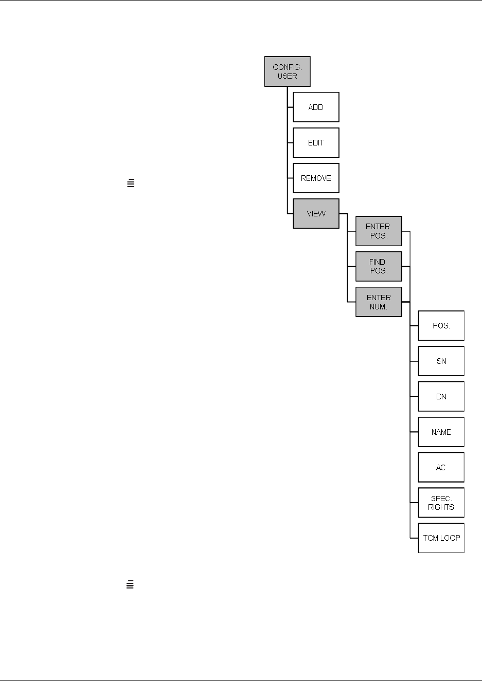
127
N0000623 01.5
Through Master handset
Figure 74
The Master handset enables you to view all the
user configurations of the wireless system. The
individual handset configuration has to be
accessed through either the position or
directory number of that handset.
Viewing user configuration
1Press MENU () - go to EXT.
SERVICE.
2Press 3OK - go to CONFIG. USER.
3Press 3OK - go to VIEW.
4Press 3OK - go to either:
• ENTER POS.
• FIND POS.
• ENTER NUM.
5Select/type the position or type the
directory number of the handset to view its
settings.
6Press 3OK - the following configuration
details are now visible:
POS. - The position
SN - Serial number/IPEI
DN - Directory number (extension
number)
NAME - Name of the handset user
AC - Authentication code
SPEC. RIGHTS - ON/Off, if ON the
handset is registered as a Master handset.
TMC LOOP - the allocated DMC channel
for the handset
7Press MENU ( ) to exit the menu.

128
Unsubscribing handsets
Note: Unsubscription of handsets requires the use of each handset to be unsubscribed from the
system, therefore you cannot use the Master handset or the DMC OAM program for
unsubscription. On a Master handset you can only unsubscribe the Master handset itself.
Note: Removing a subscription requires a password. Password default is: 0000.
To unsubscribe a handset:
1Press MENU ().
2Press < - go to MENU LOGIN.
3Press 3OK
4Press < - go to SUBSCRIPTION REMOVE.
5Press 3OK
6Enter password (0000).
7Press 3OK
The handset has been unsubscribed.
Removing handsets from the list (deregistering)
You can deregister handsets from both the DMC OAM program and the Master handset. This is
necessary when:
• you must replace the handset due to loss or breakage.
• you want to assign the handset to a user with a different telephone number.
This section provides information about:
•“Deregistering handsets through DMC OAM program” on page 129
•“Deregistering handsets through Master handset” on page 129
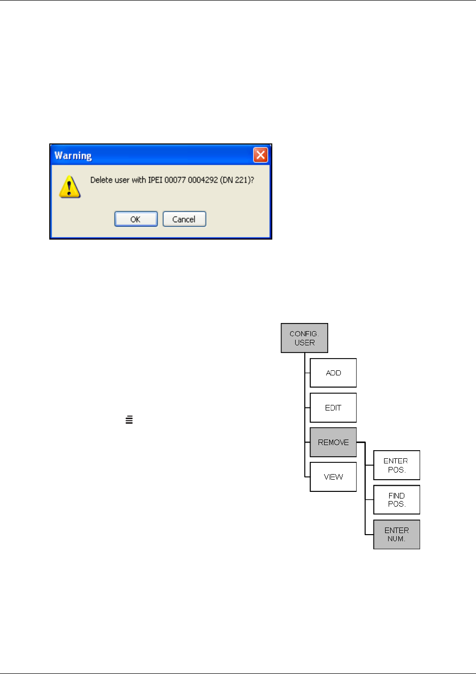
129
N0000623 01.5
Deregistering handsets through DMC OAM program
1In the Registration tab, click Read All to display all registered users on the DMC.
2Alternate-click on the cell containing the serial number of the handset in question, and then
click Delete.
A Warning window appears.
Figure 75
3Click OK to confirm.
Deregistering handsets through Master handset
Figure 76
The Master handset can remove a user from the
system either by removing the directory number or
by removing the user from an allocated position.
Removing a directory number
1Press MENU () - go to EXT. SERVICE.
2Press 3OK - go to CONFIG. USER.
3Press 3OK - go to REMOVE.
4Press 3OK - go to ENTER NUM.
5Press 3OK
6Type the directory number to be removed.
7Press 3OK - if SUCC. message appears in the
display, the directory number has been
removed.
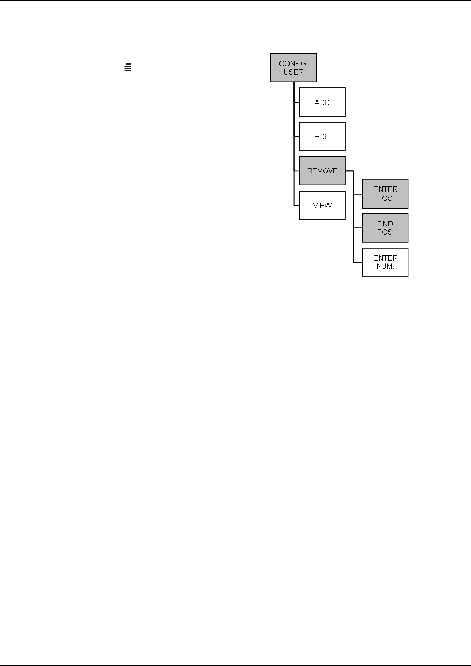
130
Removing a position
Figure 77
1Press MENU () - go to EXT. SERVICE.
2Press 3OK - go to CONFIG. USER.
3Press 3OK - go to REMOVE.
4Press 3OK - go to FIND POS. or if the
position to be removed is known go to
ENTER POS.
5Press 3OK - select or type the position to be
removed.
6Press 3OK- if SUCC. message appears in
the display, the position has been removed.
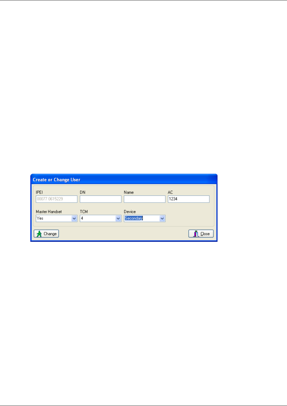
131
N0000623 01.5
Changing user settings
You can change user settings, such as the AC (authentication code) using either the DMC OAM
program or the master handset.
This section includes:
•“Through DMC OAM program” on page 131
•“Through the Master handset” on page 132
Through DMC OAM program
1In the Registration tab, click Read All to display all registered users on the DMC.
2Alternate-click on the cell containing the serial number of the handset in question, and then
click Change.
A Create or Change User dialog box appears.
Figure 78
3Change settings, and click Change to confirm.
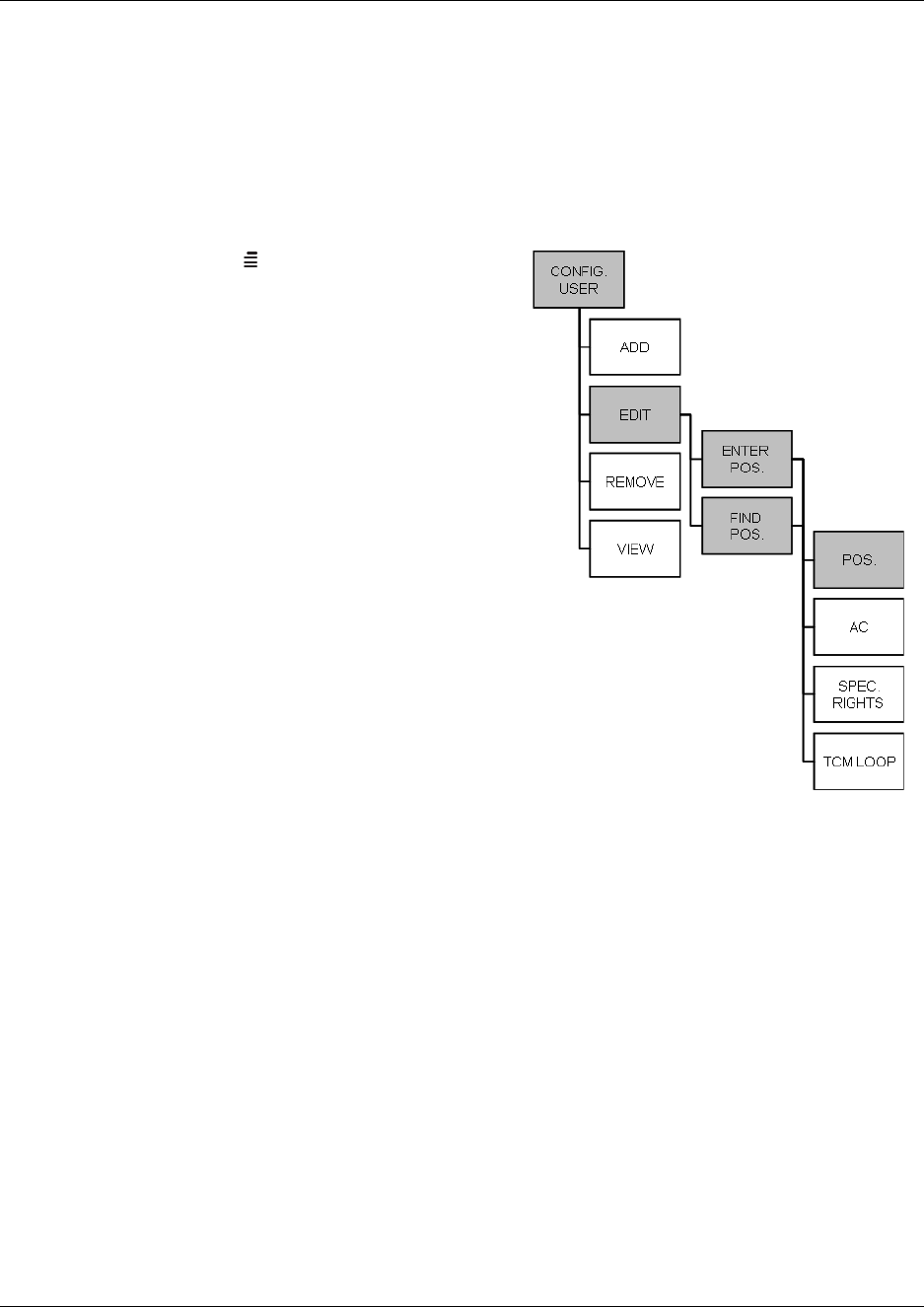
132
Through the Master handset
The Master handset has the capability to edit the following handset parameters for all registered
handsets: Position, authentication code (AC), special rights, and TCM loop number.
Changing position
Figure 79
1Press MENU () - go to EXT. SERVICE.
2Press 3OK - go to CONFIG. USER.
3Press 3OK - go to EDIT.
4Press 3OK - go to FIND POS. and select the
position from the list, or if the position to be
changed is known go to ENTER POS. and
enter the position.
5Press 3/OK -the selected/entered position is
shown in the display with a change to prompt.
Enter the new position.
Press 3/- if SUCC. message appears in
the display, the new position has been
accepted.
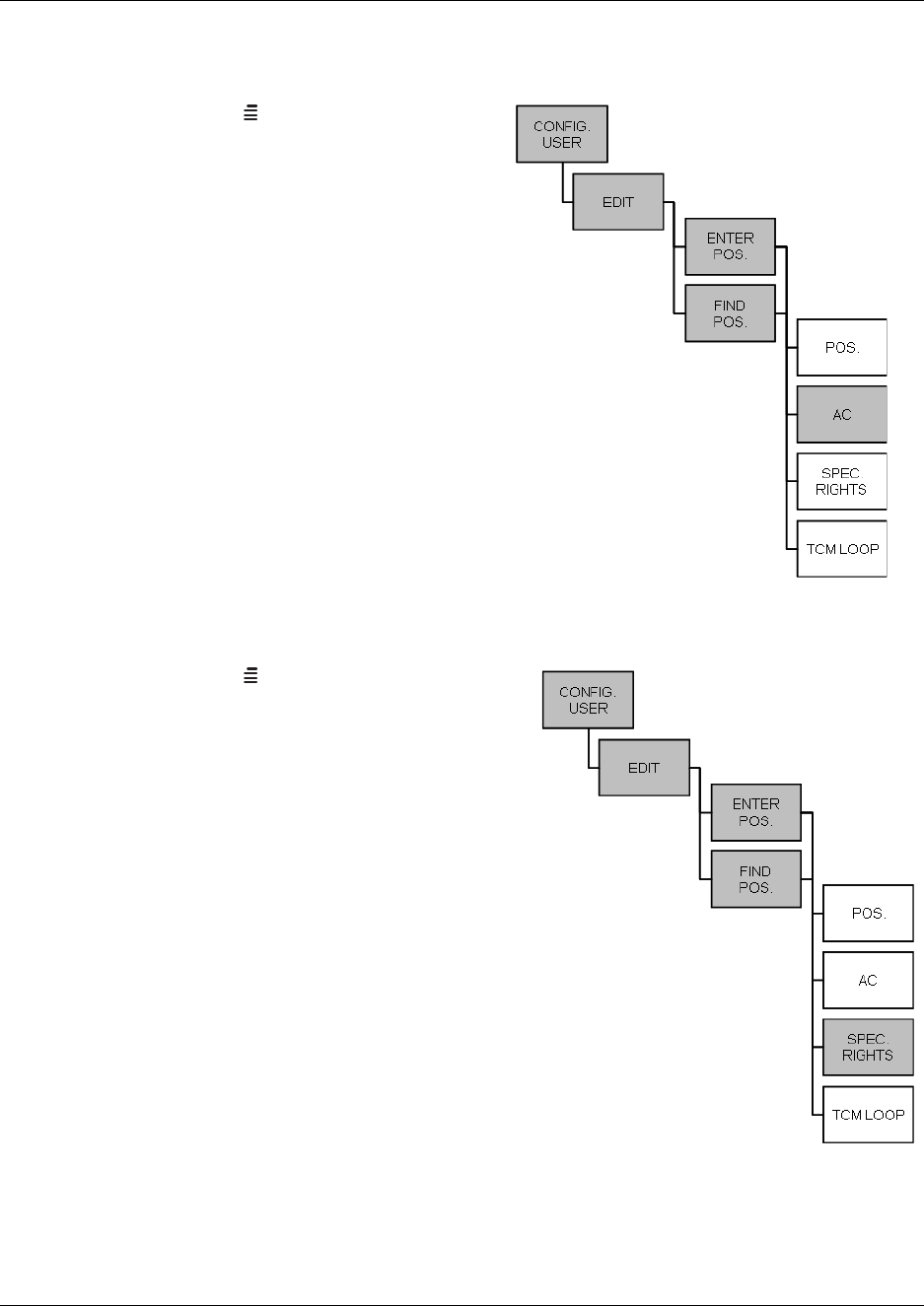
Chapter 9 Handset management
N0000623 01.5
Changing authentication code
Master handset: Changing an AC
Press MENU () - go to EXT. SERVICE.
Press 3/- go to CONFIG. USER.
Press 3/- go to EDIT.
Press 3/- go to FIND POS. and select
the position from the list, or if the position to
be changed is known go to ENTER POS.
and enter the position.
Press 3/- go to AC.
Press 3/- the selected AC is shown in
the display with a change to prompt. Enter
the new AC code (max. eight digits).
Press 3/- if SUCC. message appears in
the display, the new AC has been accepted.
Changing special rights
Master handset: Changing special rights
Press MENU () - go to EXT. SERVICE.
Press 3/- go to CONFIG. USER.
Press 3/- go to EDIT.
Press 3/- go to FIND POS. and select the
position from the list, or if the position to be
changed is known go to ENTER POS. and
enter the position.
Press 3/- go to SPEC. RIGHTS.
Press 3/- select between the two options:
SPEC. RIGHTS or NO SPEC. RIGHTS to
give the handset a Master handset status.
Press 3/- to confirm the special rights
selection. A SUCC. message appears in the
display.
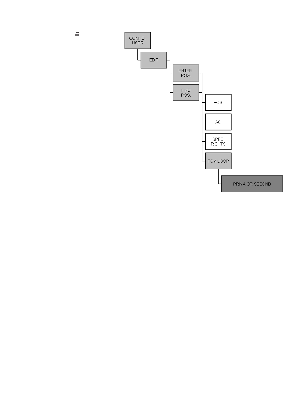
Chapter 9 Handset management
Digital Mobility System Installation and Configuration Guide
Changing TCM loop number
Master handset: Changing a TCM loop number
Press MENU () - go to EXT.
SERVICE.
Press 3/- go to CONFIG.
USER.
Press 3/- go to EDIT.
Press 3/- go to FIND
POS. and select the position
from the list, or if the position
to be changed is known go to
ENTER POS. and enter the
position.
Press 3/- go to TCM
LOOP.
Press 3/- select between
the two options: PRIMA or
SECOND, depending on
which DMC the TCM loop
number should be changed.
Press 3/- The Primary/
Secondary TCM loop number is shown in the display with a change to prompt. Enter the new
TCM loop number
Press 3/- if SUCC. message appears in the display, the new TCM loop number has been
accepted.
Refer to “Download Flash” on page 175 for information about firmware downloads to the handset.

Chapter 9 Handset management
N0000623 01.5

Digital Mobility System Installation and Configuration Guide
Chapter 10
System Management
This section provides you with information about the DMC OAM program and the Digital
Mobility Service Tool and describes how the programs are used for system management. It also
describes how to read system information through the Master handset.
This section provides information about:
•“Using the DMC OAM program” on page 136
•“Using the Digital Mobility Service Tool” on page 141
•“Define and view system settings” on page 145
•“Advanced features” on page 162
•“Saving configuration data” on page 178
•“Troubleshooting error messages” on page 180
•“Should you need to report a problem” on page 182
Using the DMC OAM program
The DMC OAM program is used for registration of handsets, sending MSF messages (Message
Service Function) and viewing status information.
This section provides information about:
•“Registration” on page 136
•“MSF Messages (Message Service Function)” on page 136
•“Checking Status Information” on page 140
Registration
For information about registration, see “Register handsets through DMC OAM program” on page
111.
MSF Messages (Message Service Function)
With the MSF Demo tab you can send text messages to any MSF compatible handset connected to
the DMC. Also any MSF-compatible handset connected to the DMC can send text messages to the
DMC.
Note: The MSF Demo tab is only a demo of messaging services, but it can be used for some very
simple messaging. It is the interface intended to be used by a third-party application, such as an
alarm server.
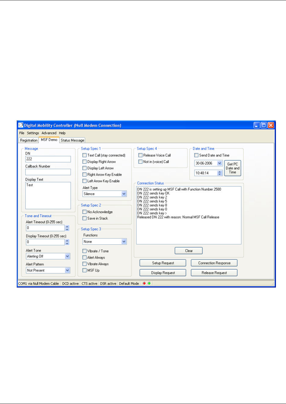
137
N0000623 01.5
Note: The protocol on the RS232 port of the DMC has elements for administration and
maintenance of the DMC and base stations. It also has a set of Supplementary Service elements
useful for remote control applications, for paging systems, and for exchanging written messages.
Those are designed for use by third-party application developers, which typically addresses
specific niche markets, such as care facilities, hotels, prisons and mental institutions. The DMC
OAM program is not developed to fulfill any of those needs. Some of the Supplementary Service
elements are most useful in automatic systems/applications, therefore, only a subset of the features
is shown in the MSF Demo tab.
Sending text messages from DMC to a handset
1From the Main window (of the DMC OAM program), click the MSF Demo tab.
2In the Message area, type the directory number of the receiver handset and the message to be
sent. If you want the receiver to call you back, you can also type a callback number.
3In the MSF Demo tab you can also define different settings for the receiver handset, such as
how the handset displays the message, and how the display behaves when receiving an MSF.
•Setup Spec 1: Use these fields to define how the display on the receiver handset behaves
when receiving a text message.
•Setup Spec 2: Use these fields to define how the receiver handset handles the text
message.
•Setup Spec 3: Use these fields to define how the receiver handset acts when receiving a
text message.

138
•Setup Spec 4: Use these fields to define how the receiver handset handles voice calls
when receiving a text message.
•Tone and Timeout: Use these fields to define the type of tone the receiver handset sends
when receiving a text message.
•Date and Time: Use these fields to set date and time, and send this information with the
text message.
4If you want to stay connected and send more than one text message, select the Text Call (stay
connected) check box in the Setup Spec 1 area.
5Click Setup Request to send the text message.
6In the Connection Status area, an MSF connection confirmation from the receiver handset is
displayed when the text message is received (to confirm the connection the user of the handset
must press 3/OK on the handset).
If an error occurs during connection, or if the handset releases the call, a release text appears in
the Connection Status area. The release text could, for example, be one of the following:
7If you have received a connection confirmation, and if you selected the Text Call (stay
connected) check box in the Setup Spec 1 area, the DMC is still connected to the handset and
it is possible to send more text messages.
• Type the new text message in the Display Text field (Message area), and then click
Display Request.
8To release the connection to the handset:
• If the Text Call (stay connected) check box is not selected, then the call is automatically
released after the transfer of message.
• If the Text Call (stay connected) check box is selected, click Release Request to release
the connection.
9Click Clear to clear the Connection Status area.
Normal release the text message has been received by handset
Timer expiry time-out occurred when trying to send MSF to handset
Handset is out of range no contact to handset established
Handset is busy handset is busy with another MSF connection
Unknown handset the handset is unknown to the system - check directory
number
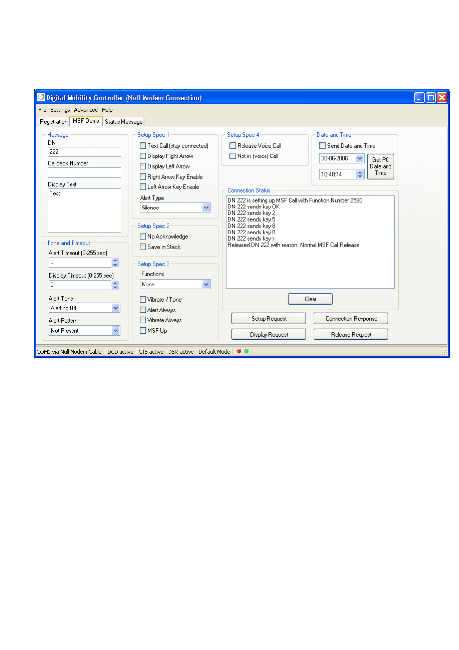
139
N0000623 01.5
Receiving text messages from handset to DMC
1From the Main window (of the DMC OAM program), click the MSF Demo tab.
Figure 83
2The Connection Status area shows if a text message has been sent from a handset to the
DMC.
3To respond to the message and set up a connection, type the DN of the handset in the Message
area. The DN is shown in the Connection Status area. Then, click Connection Response.
4To release the connection to the handset, type the DN of the handset in the Message area. The
DN is shown in the Connection Status area. Then, click Release Request.
5Click Clear to clear the Connection Status area.
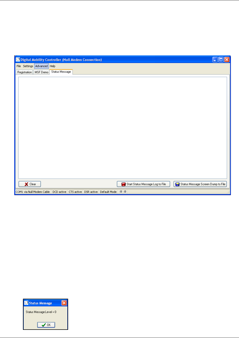
140
Checking Status Information
In the Status Message tab all received status messages from the DMC is shown (a text string with
debug information from the DMC). It provides an overview of activities performed in the system.
Figure 84
The frequency of arrival of these status messages is determined by the status message level. The
level can have a value between 0 and 3. A value of 3 makes the DMC send a message very often,
and a value of 0 (zero) disables most messages.
How to set status message level
•On the Advanced menu, point to Set Message Level, and select the wanted level.
A confirmation of the change of status message level is shown in the status bar.
How to read status message level
1On the Advanced menu, point to Read Message Level. A Status Message window appears
showing the current status message level in the DMC.
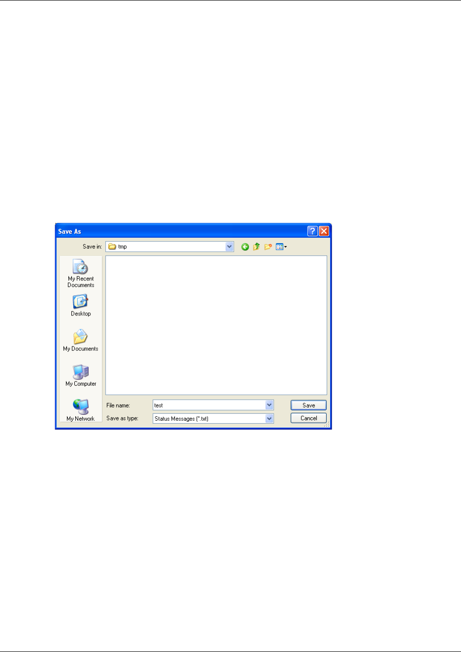
141
N0000623 01.5
2Click OK.
How to save status messages
Saving status messages is useful if you are experiencing problems with the system and need to
send the status messages to your local service center.
1You can save the status messages as text or as a screen dump in a file.
• Click Start Status Message Log to File to save the status messages as a text file.
Note: The Start Status Message Log to File command is also available from the File
menu.
• Click Status Message Screen Dump to File to save a screen dump of the status messages.
A Save As dialog box appears.
2Indicate in which folder and under what name the file should be saved, and then click Save.
The status messages are saved in a file.
Using the Digital Mobility Service Tool
The Digital Mobility Service Tool is used for repeater programming and handset adjustment.
This section provides information about:
•“Repeater programming” on page 142
•“Handset adjustment” on page 142
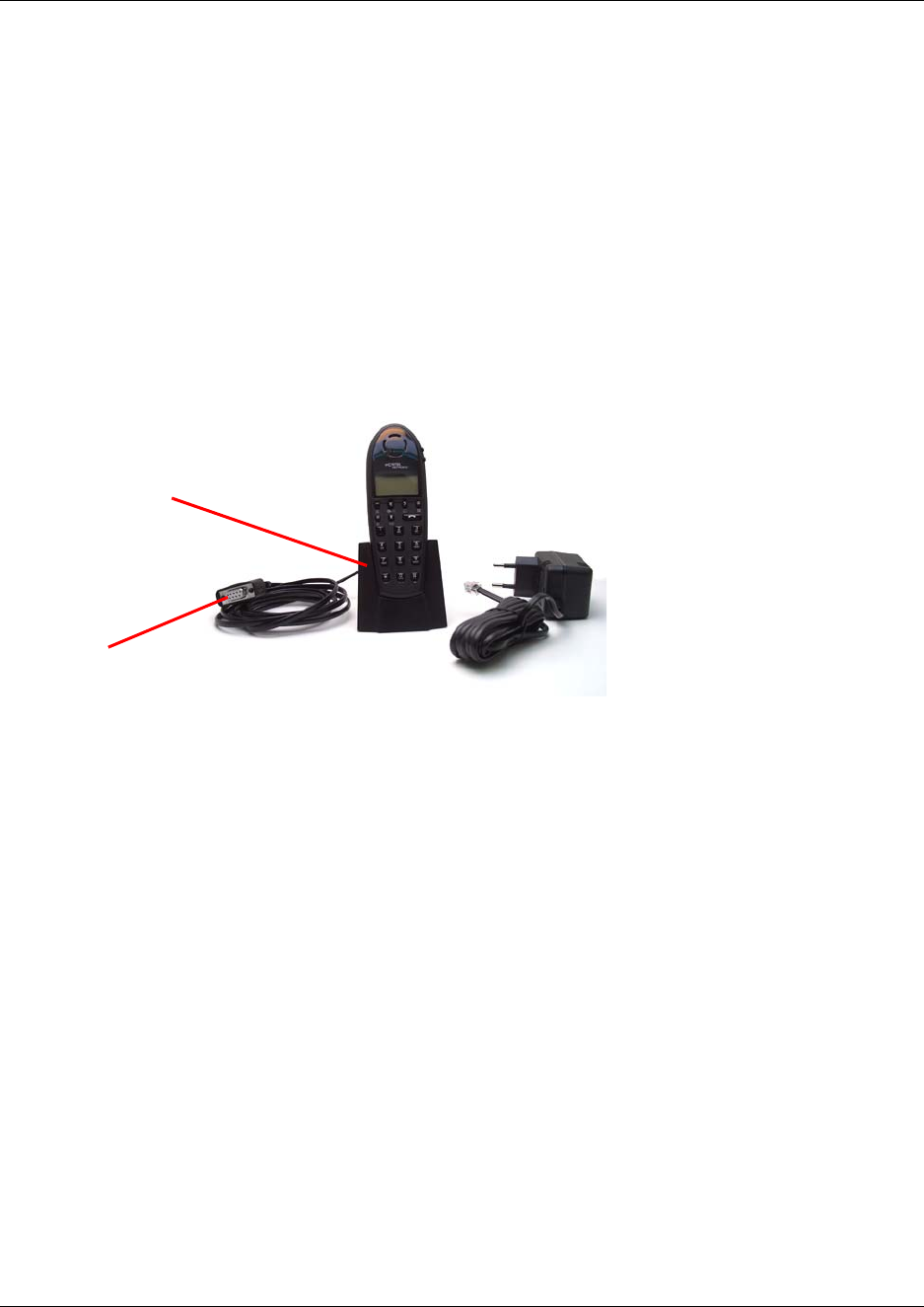
142
Repeater programming
For information about repeater programming, see “Programming the repeater with the Digital
Mobility Service Tool” on page 75.
Handset adjustment
The programming kit for handset 7420 (NT7B65LL) (see illustration below) consists of:
• serial cable
• programming stand
• 110V power supply
The programming kit for handset 413X, 414X, 743X and 744X (NT7B65LK) consists of:
• serial cable
• modular connector adaptor
Note: For adjusting the handset 413X, 414X, 743X and 744X you use the charger
accompanying the handset.
Note: For adjusting the handset you also need the programming software (Digital Mobility
Service Tool). The Digital Mobility Service Tool is not part of the programming kit. The program
can be downloaded from the host system CD for Norstar systems and from under the Client Install
button on the Business Communications Manager Unified Manager first page.
Set up of the hardware for handset adjustment:
1Connect the serial cable to the programming stand/charger and Com port of your computer.
2Place the handset in the programming stand/charger.
The handset is now ready for programming via the Digital Mobility Service Tool.
Programming stand
Serial cable
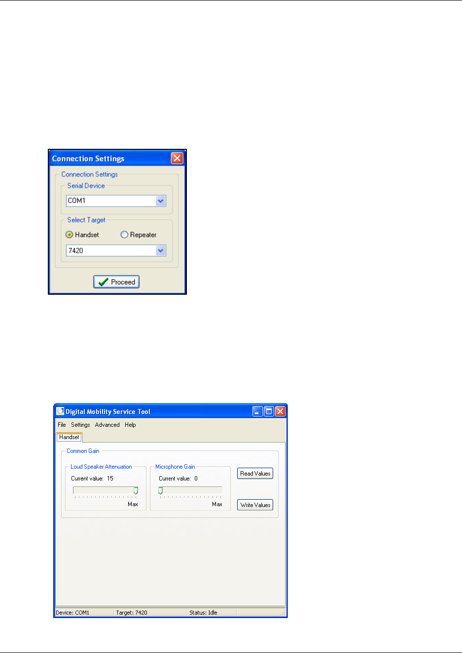
N0000623 01.5
To adjust the handset from the Digital Mobility Service Tool:
Before you start adjusting the handset, ensure that the programming stand/charger is
connected to the computer and that the handset is placed in the programming stand/charger
(Refer to “Set up of the hardware for handset adjustment:” on page 142).
Open the Digital Mobility Service Tool on your desktop.
A Digital Mobility Service Tool window appears.
Select a Com port from the Serial Device list.
Click Handset, and then select the desired handset model from the list.
Click Proceed.
When a handset 7420 is selected, the following dialog box appears.
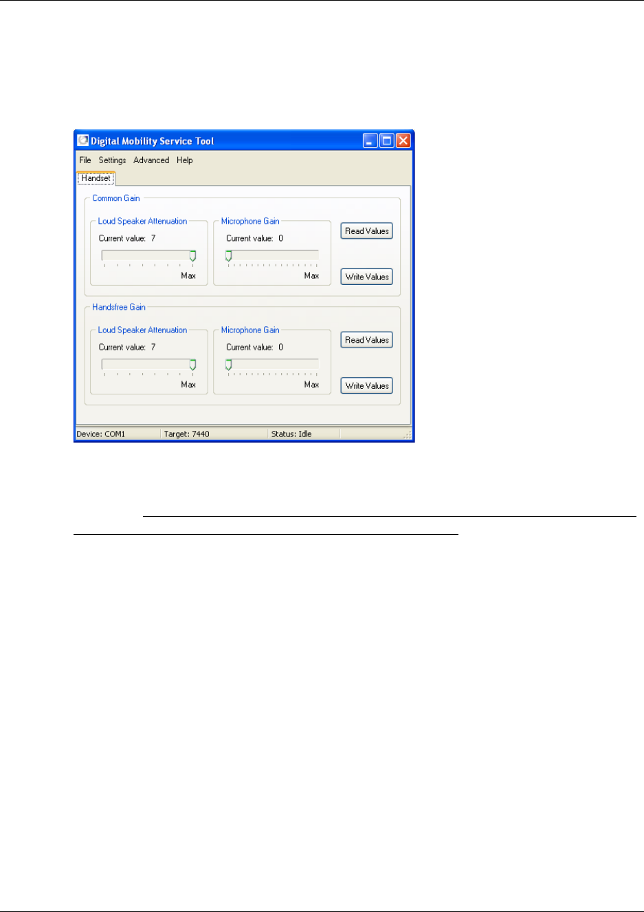
A message is shown in the status bar when handset is connected.
When a handset model that can be used handsfree, such as 744X, is selected, the following
dialog box appears.
Under Common Gain, click Read Values to display the current values for the loud speaker
volume and microphone gain.
It is recommended not to change any of the default values as they will impact the
system and create potentially echo or other voice quality issues.
Change the values, and then click Write Values.
If adjusting a handset that can be used handsfree:
•Under Handsfree Gain, click Read Values to display the current values for the loud
speaker volume and microphone gain.
• Change the values, and then click Write Values.
To adjust another handset:
• Select the Connection Settings command from the Settings menu.
• Select a handset from the list in the appearing Connection Settings dialog box, and then
repeat steps 5 to 8.
On the File menu, click Exit. This will close the program. The handset has now been adjusted.
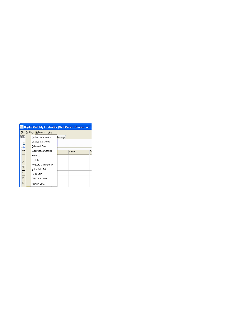
145
N0000623 01.5
Define and view system settings
Through the DMC OAM program, the Digital Mobility Service Tool and the Master handset it is
possible to define and view different settings of the system.
This section provides information about:
•“System settings in the DMC OAM program” on page 145
•“System settings in the Digital Mobility Service Tool” on page 157
•“System settings in the Master handset” on page 159
System settings in the DMC OAM program
From the Settings menu in the DMC OAM program you can reach commands for viewing and
defining system settings.
This section contains a description of each of these commands:
•“System Information” on page 146
•“Change Password” on page 147
•“Date and Time” on page 147
•“Suppression Control” on page 147
•“RFP PCS” on page 148
•“Statistic” on page 149
•“Measure Cable Delay” on page 152
•“Voice Path Gain” on page 153
•“PSTN Gain” on page 154
•“DSP Tone Level” on page 156
•“Restart the DMC” on page 157
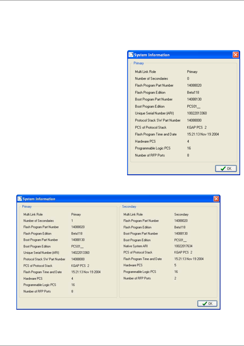
146
System Information
This information may be used when troubleshooting or diagnosing problems in the system.
Figure 88
1On the Settings menu, click System
Information.
A System Information window
appears.
The window contains miscellaneous
information from the DMC.
2Click OK to close the window.
Figure 89
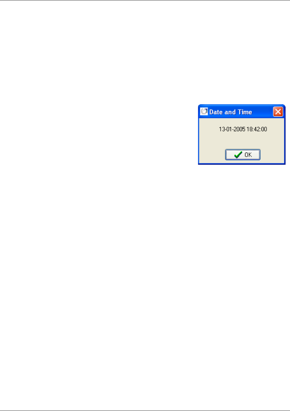
147
N0000623 01.5
Change Password
The Change Password command is used for changing the password, that you will be prompted
when starting the DMC OAM program.
Refer to “Change password” on page 102 for the procedures for changing a password.
Date and Time
Figure 90
1On the Settings menu, click Date and Time.
A Date and Time dialog box appears.
The dialog box contains information on DMC system
time. The date and time are read from the host system.
2Click OK to close the dialog box.
Suppression Control
Using the Suppression Control command makes the handsets function better in different noisy
environments.
Refer to “Suppression control” on page 103 for more information on suppression control.
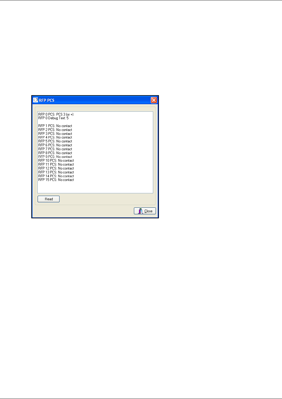
148
RFP PCS
The RFP PCS command requests the Product Change Status (PCS) from all base stations (RFPs).
Using this command you can check if there is contact to the base stations. You can also compare
the base stations and check software versions.
1On the Advanced menu, click RFP PCS.
A RFP PCS dialog box appears.
Figure 91
2Click Read.
The number of the base station (RFP) and the corresponding PCS is shown as a text string.
3Click Close to close the dialog box.
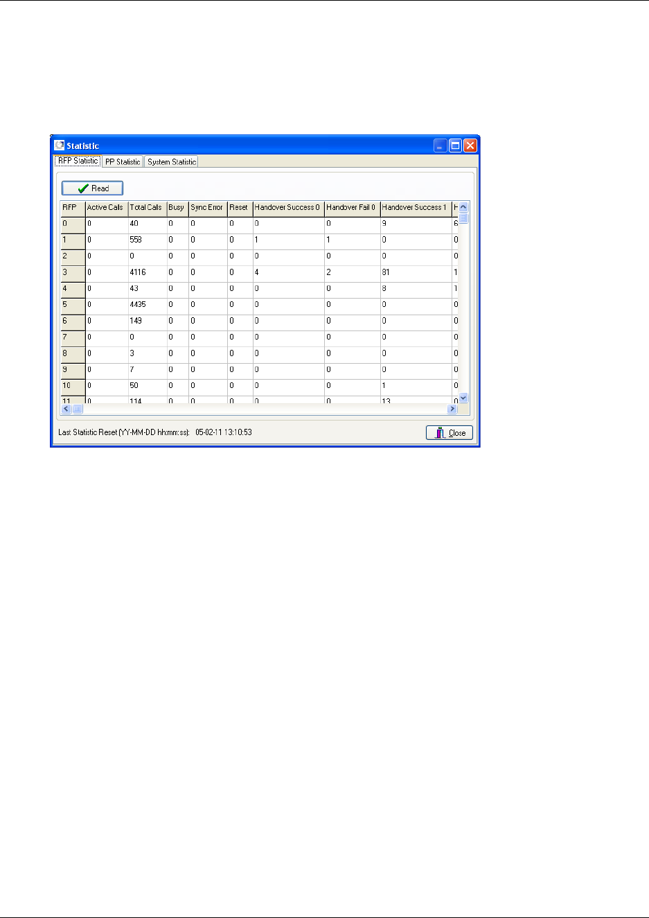
149
N0000623 01.5
Statistic
Use this command to get statistic information from the base stations (RFPs), the handsets (PPs),
and general system information.
Figure 92
Base station information
1On the Settings menu, click Statistic.
A Statistic dialog box appears showing the RFP Statistic tab as default.
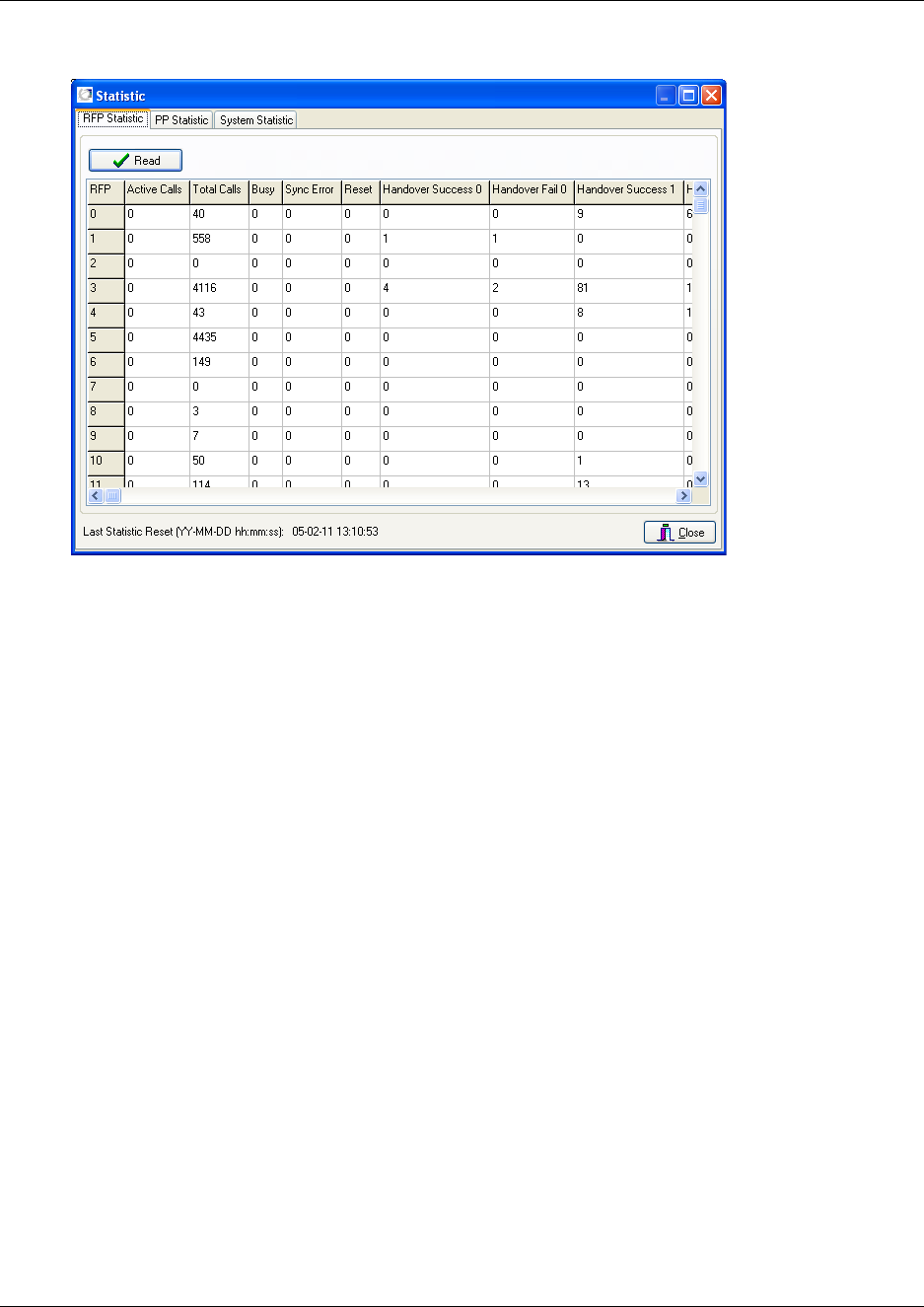
150
Figure 93
The RFP Statistic tab displays statistic records from base stations.
2Click Read.
The received statistic record contains data of all the base stations on the system: Handovers
(success/fail), resets, sync errors, number of outgoing/incoming calls, time of the last statistic
reset, etc.
3Click Close.
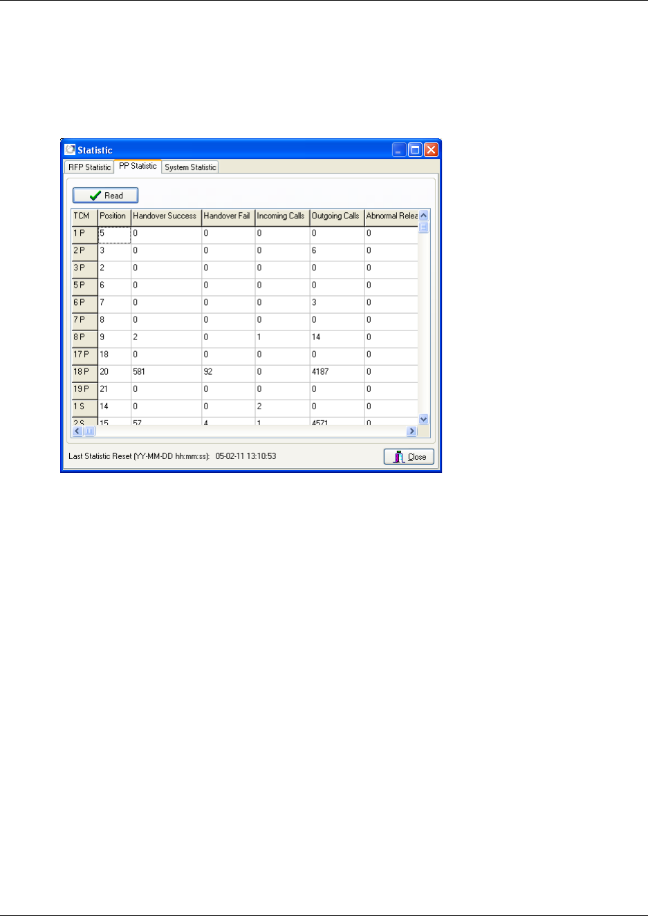
151
N0000623 01.5
Handset information
1On the Settings menu, click Statistic, and then click the PP Statistic tab.
The following dialog box appears.
Figure 94
The PP Statistic tab displays statistic records from handsets.
2Click Read to show all registered handsets.
The received statistic record contains data of all the handsets on the system: Position,
handovers (success/fail), resets, sync errors, number of outgoing/incoming calls, time of the
last statistic reset, etc.
3Click Close.
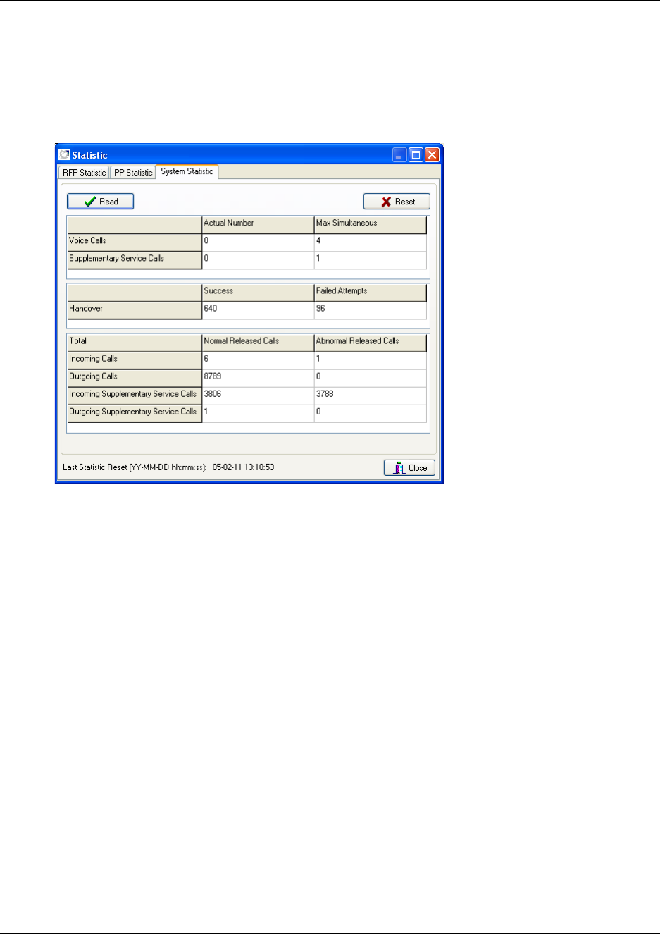
152
General system information
1On the Settings menu, click Statistic, and then click the System Statistic tab.
The following dialog box appears.
Figure 95
The System Statistic tab displays general system information and provides a quick overview.
2Click Read.
3Optionally, you can click Reset if you want to reset all data when read.
4Click Close.
Measure Cable Delay
The Measure Cable Delay command is used to measure the delay from the DMC to the base
stations.
Note: The delay must be measured the first time after a base station has been connected.
For more information about cable delay measurement, refer to “Cable Delay Measurement” on
page 105.
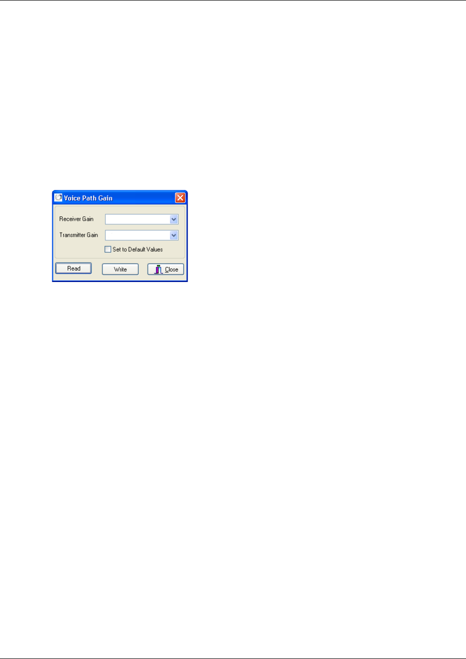
153
N0000623 01.5
Voice Path Gain
The Voice Path Gain command is useful if you are experiencing low voice path volume or a line
echo when using the handset. Using the Voice Path Gain command it is possible to increase/
decrease the voice path volume or minimize line echo.
Note: When testing the voice path volume or line echo, always call an external line for a reliable
measurement.
1On the Settings menu, click Voice Path Gain.
A Voice Path Gain dialog box appears.
Figure 96
The values shown in the dialog box are the current system settings.
2Select the wanted values from the Receiver Gain list and the Transmitter Gain list.
• If you are experiencing a low voice path volume (and the volume in the handset is already
set to maximum), you can adjust the voice path volume by increasing the values.
• If you are experiencing a line echo when using the handset, you can adjust the voice path
volume by decreasing the values.
Note: The more you increase the voice path volume the higher is the risk of experiencing a
line echo when using the handset.
To return to the default values, click Set to Default Values Click
3Write to save the settings.
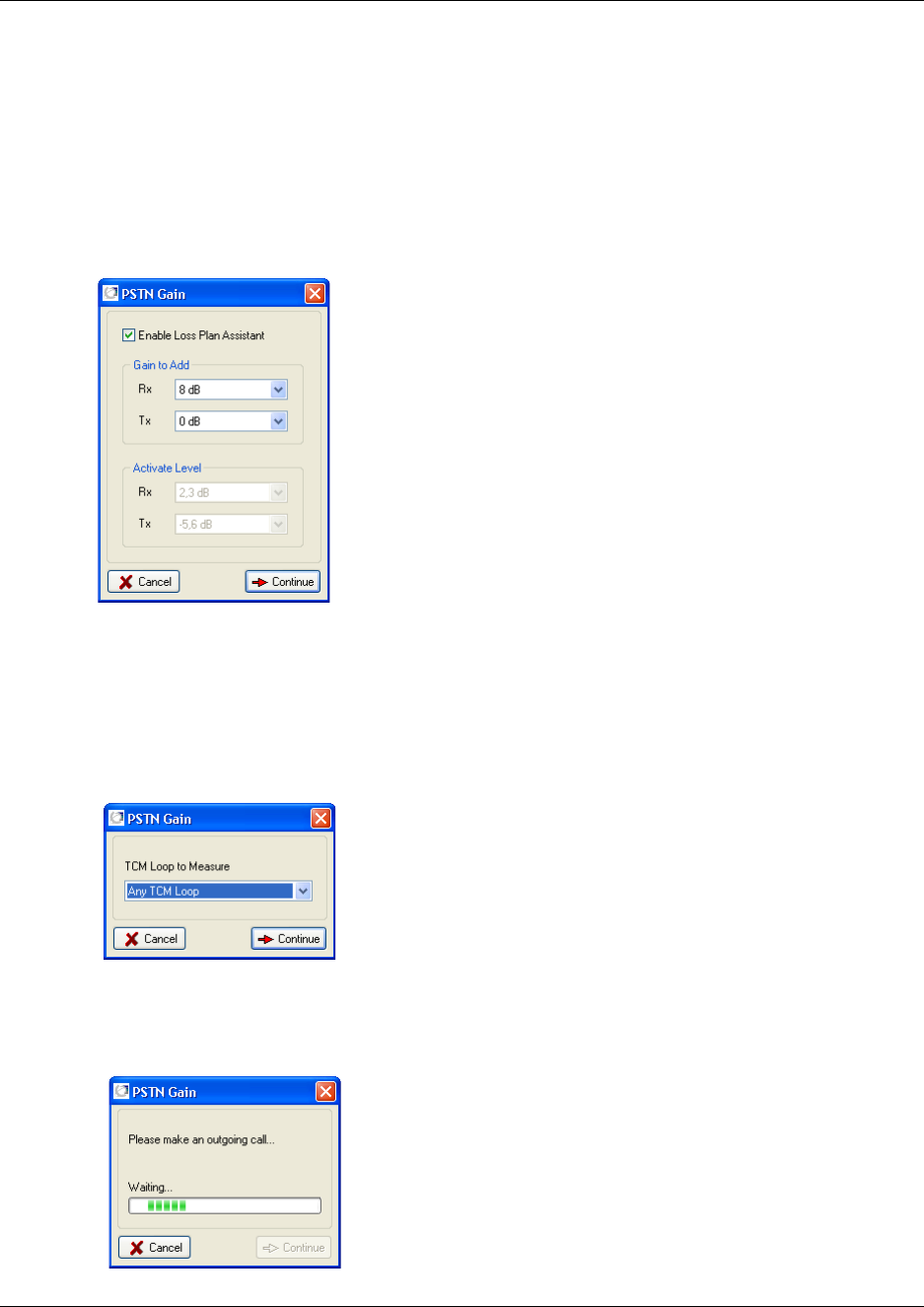
154
PSTN Gain
The PSTN Gain command (Public Switched Telephone Network) is used to compensate for losses
on a long analogue CO line.
1On the Settings menu, click PSTN Gain.
A PSTN Gain dialog box appears.
Figure 97
The dialog box displays the current values.
2Select the Enable Loss Plan Assistent check box.
3Under Gain to Add, select the wanted value for Rx (Receive) and Tx (Transmission), and
then click Continue.
The following dialog box appears.
4From the TCM Loop to Measure list, select the TCM Loop (a Public Switched Telephone
Network) you want to perform the measurement on, and then click Continue.
The following dialog box appears.
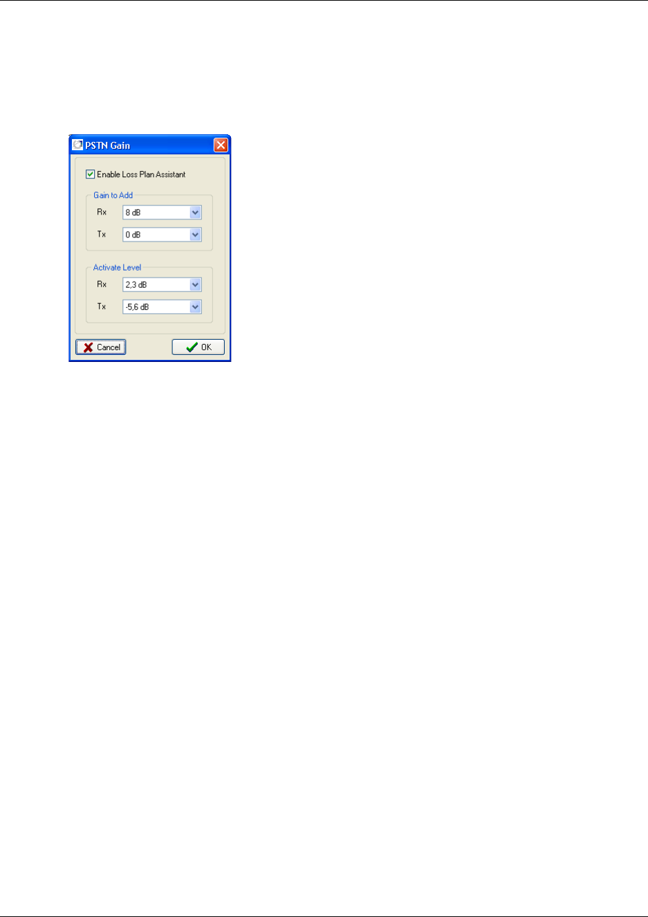
155
N0000623 01.5
5Make an outgoing call.
The DMC detects the activation level of Rx and Tx.
The PSTN Gain dialog box appears.
Figure 98
6Click OK to confirm the activate level of Rx and Tx.
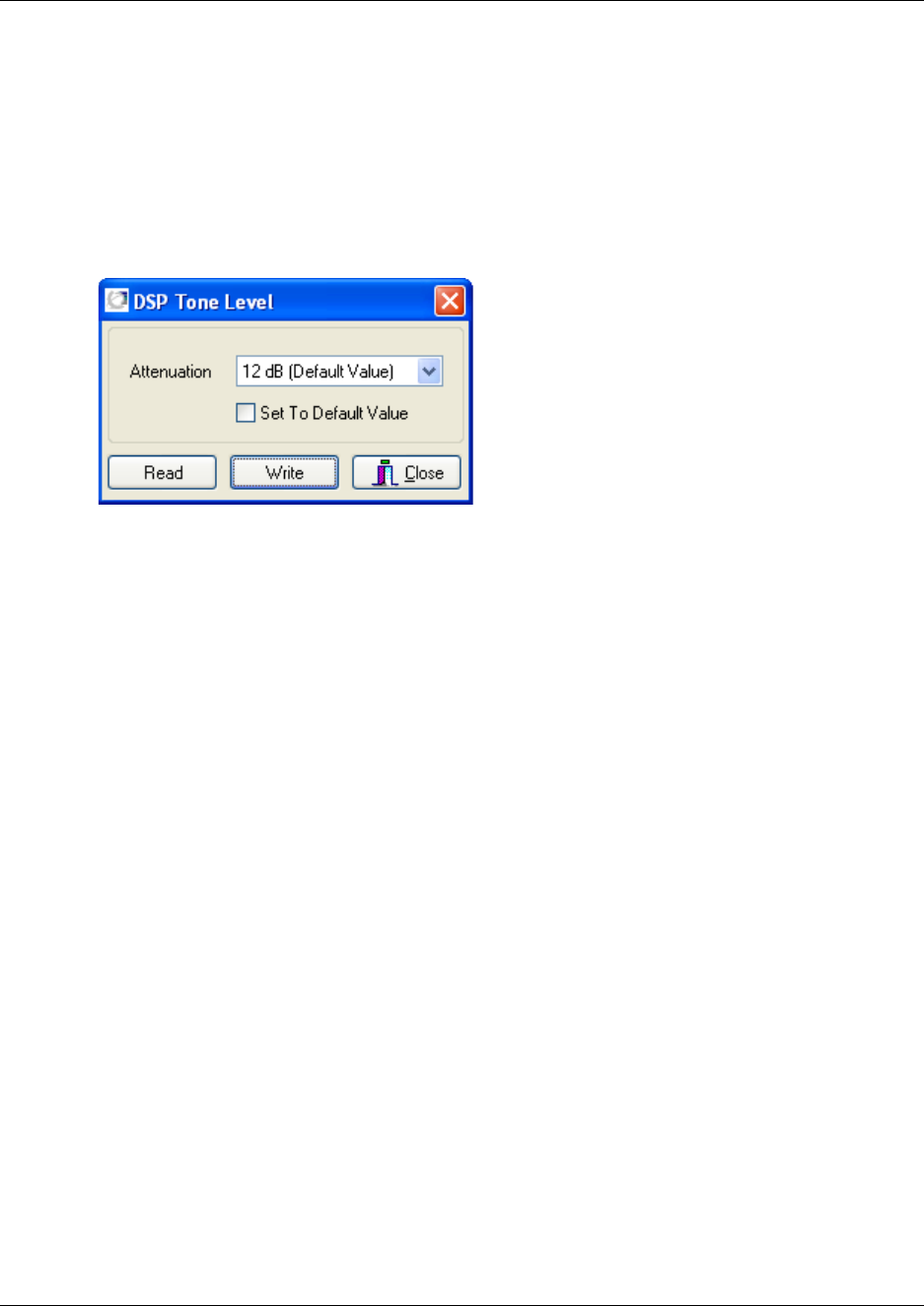
156
DSP Tone Level
The DSP Tone Level command is useful if you are experiencing a low or too high waiting tone in
your handsets.
1On the Settings menu, click DSP Tone Level.
A DSP Tone Level dialog box appears.
Figure 99
The values shown in the dialog box are the current system settings.
2Select the wanted values from the Attenuation list.
3Click Write to save the settings.
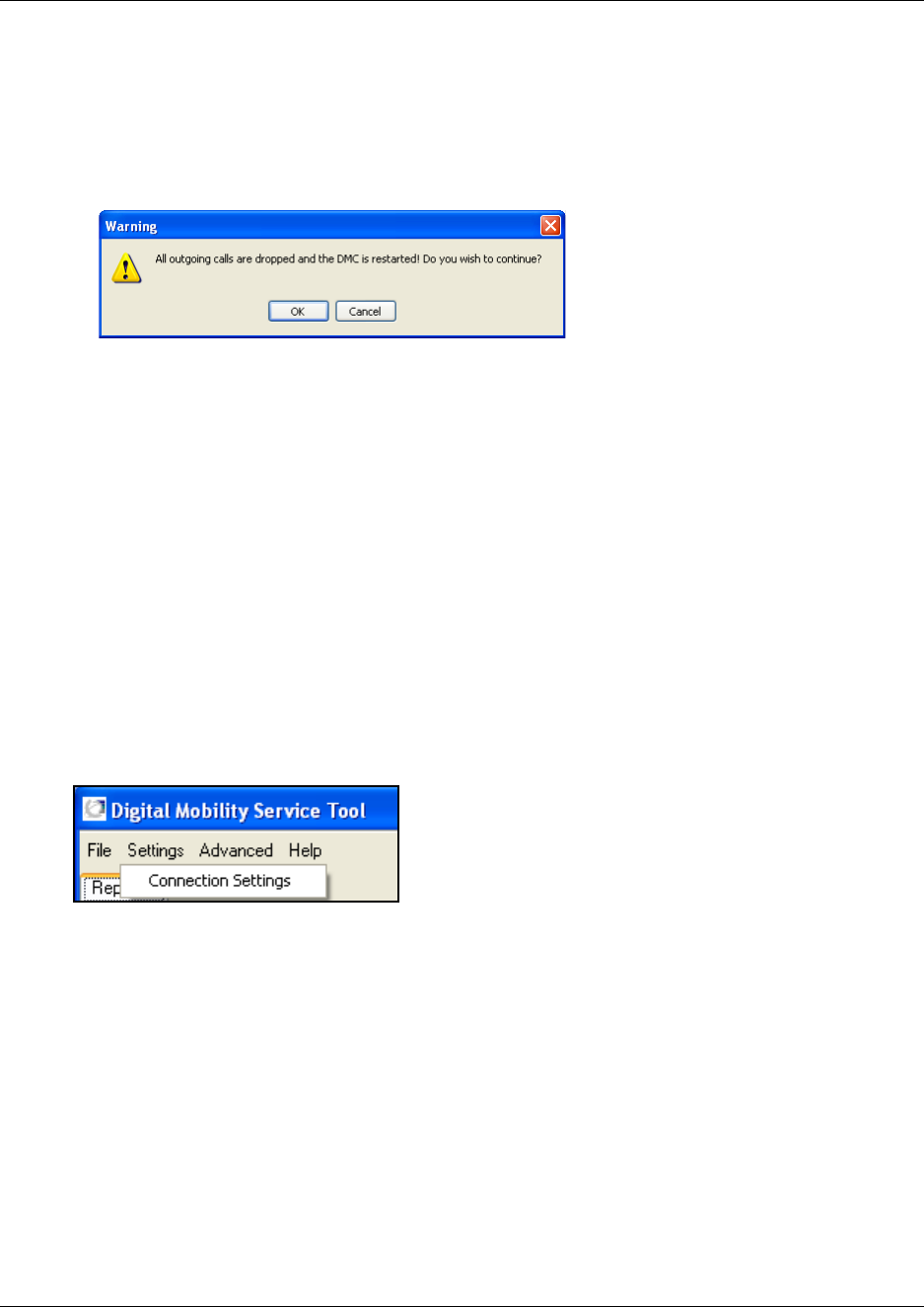
157
N0000623 01.5
Restart the DMC
1On the Settings menu, click Restart DMC.
A warning message appears.
Figure 100
2Click OK to continue.
The DMC is restarted and after a little while (depending on system size it can take from a few
seconds up to a few minutes), both base stations, repeaters and handsets are ready for use
again.
System settings in the Digital Mobility Service Tool
From the Settings menu in the Digital Mobility Service Tool you can reach a Connection Settings
command. Using this command you can easily change Com port settings, change to another
repeater or handset without having to close the program after each repeater programming, handset
adjustment, or software download.
This section contains a description of:
•“Connection Settings” on page 158
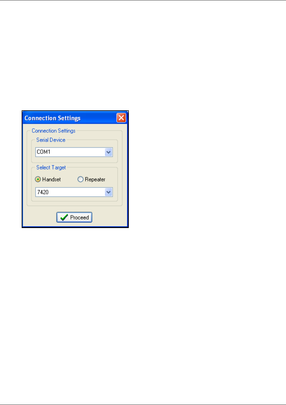
158
Connection Settings
1On the Settings menu, click Connection Settings.
A Connection Settings dialog box appears.
2Select a Com port from the Serial Device list.
3Click either Handset or Repeater, and then select the handset/repeater in question.
4Click Proceed.
Figure 101
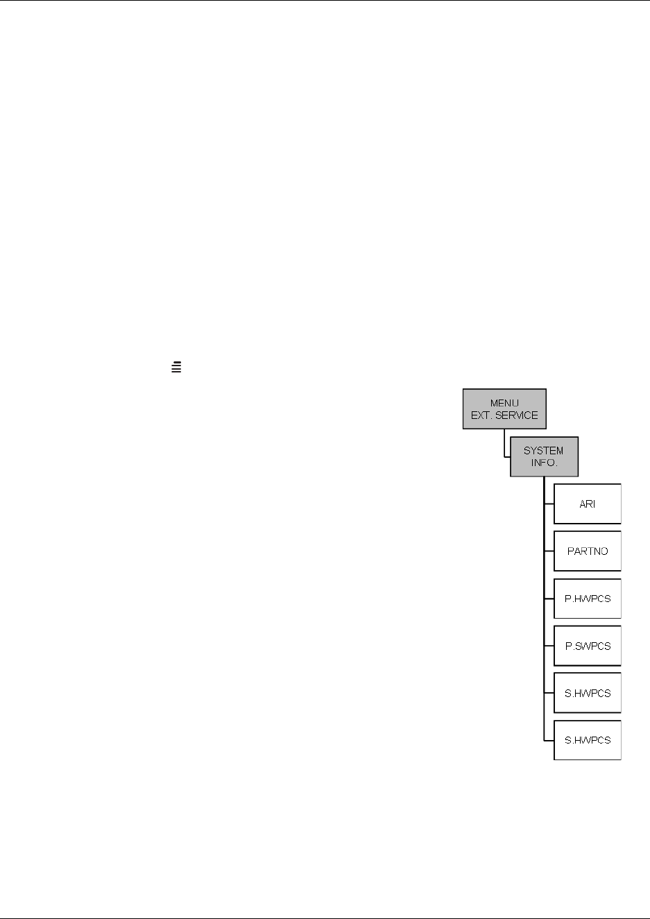
159
N0000623 01.5
System settings in the Master handset
This section provides information about reading out system information and handset information
using the Master handset.
This section provides information about:
•“Reading system information from a Master handset” on page 159
•“Reading handset information from a Master handset” on page 160
•“Reading base station information from a Master handset” on page 160
•“Reading statistics from a Master handset” on page 161
Reading system information from a Master handset
The Master handset can read out system information as a quick way of checking the DMC settings.
Figure 102
1Press MENU () - go to EXT. SERVICE.
2Press 3OK - go to SYSTEM INFO.
3Press 3OK
The following DMC settings can be accessed:
ARI - The ARI code of the DMC
PARTNO - The part number of the DMC software
P.HWPCS - The Primary DMC hardware edition number
P.SWPCS - The Primary DMC software edition number
S.HWPCS - The hardware edition number of the
Secondary DMC in a linked system
S.SWPCS - The software edition number of the Secondary
DMC in a linked system
Note: For information on Boot Program Part Number, Boot
Program Edition, PCS of Protocol Stack, Flash Program Time
and Date, Programmable Logic PCS and Number of RFP Ports
you need to use the DMC OAM program, refer to System
Information on page 146.
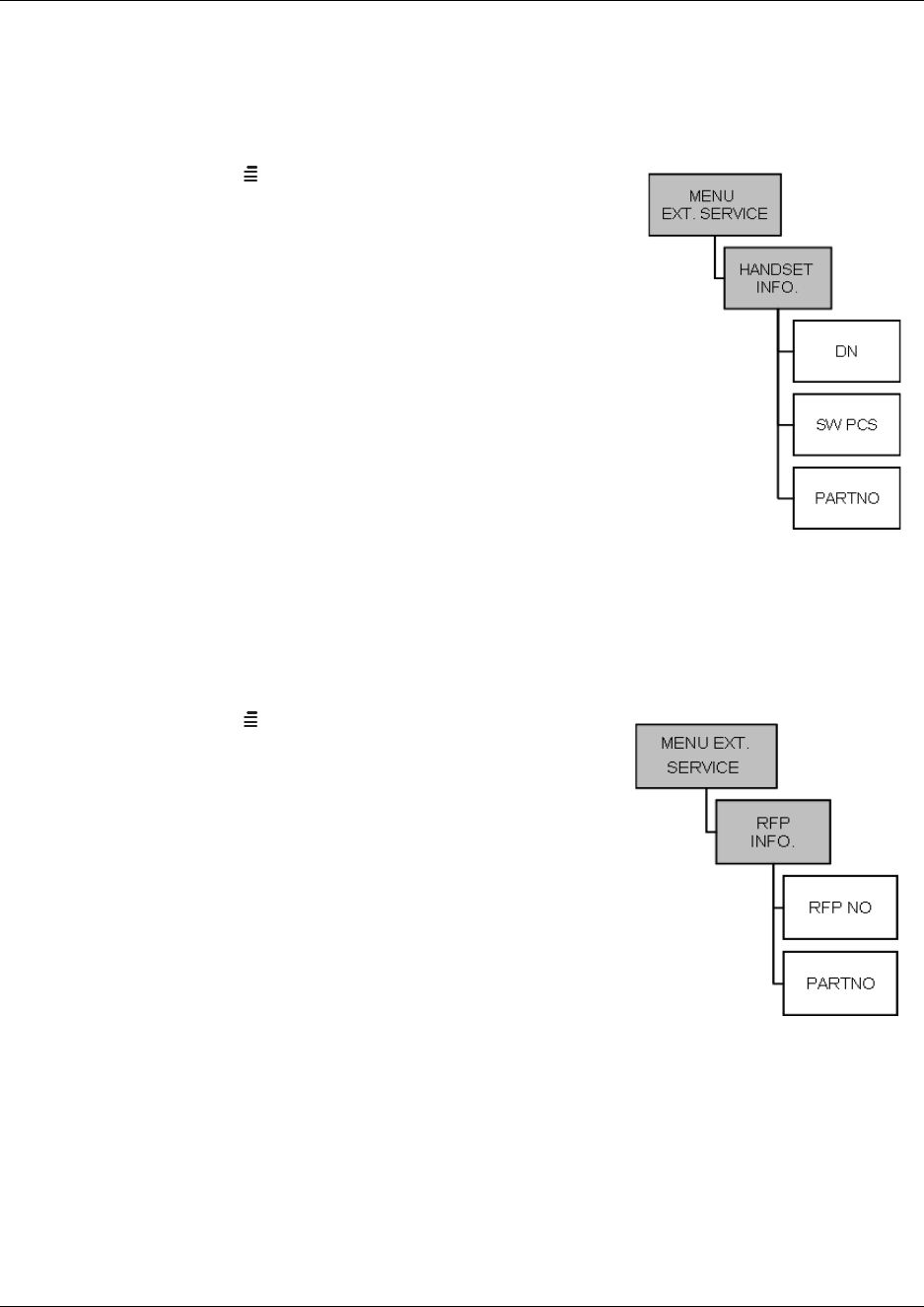
160
Reading handset information from a Master handset
The Master handset can read out information of the individual handsets.
Figure 103
1Press MENU () - go to EXT. SERVICE.
2Press 3OK - go to HANDSET INFO.
3Press 3OK
The following information can be accessed:
DN - (Directory number) The extension number of the
handset
SW PCS - The part number of the handset software
PARTNO - The handset software edition number
All the above three lines appear in the display. Use the < >
keys to scroll to the next/previous handset.
Reading base station information from a Master handset
Base station number and the software editions of the base stations can be viewed from the Master
handset.
Figure 104
1Press MENU () - go to EXT. SERVICE.
2Press 3OK - go to RFP INFO.
3Press 3OK
The following information can be accessed:
RFP NO - The number of the base station
PARTNO - The part number of the base station software
Both lines appear in the display. Use the < > keys to scroll
to the next/previous base station.
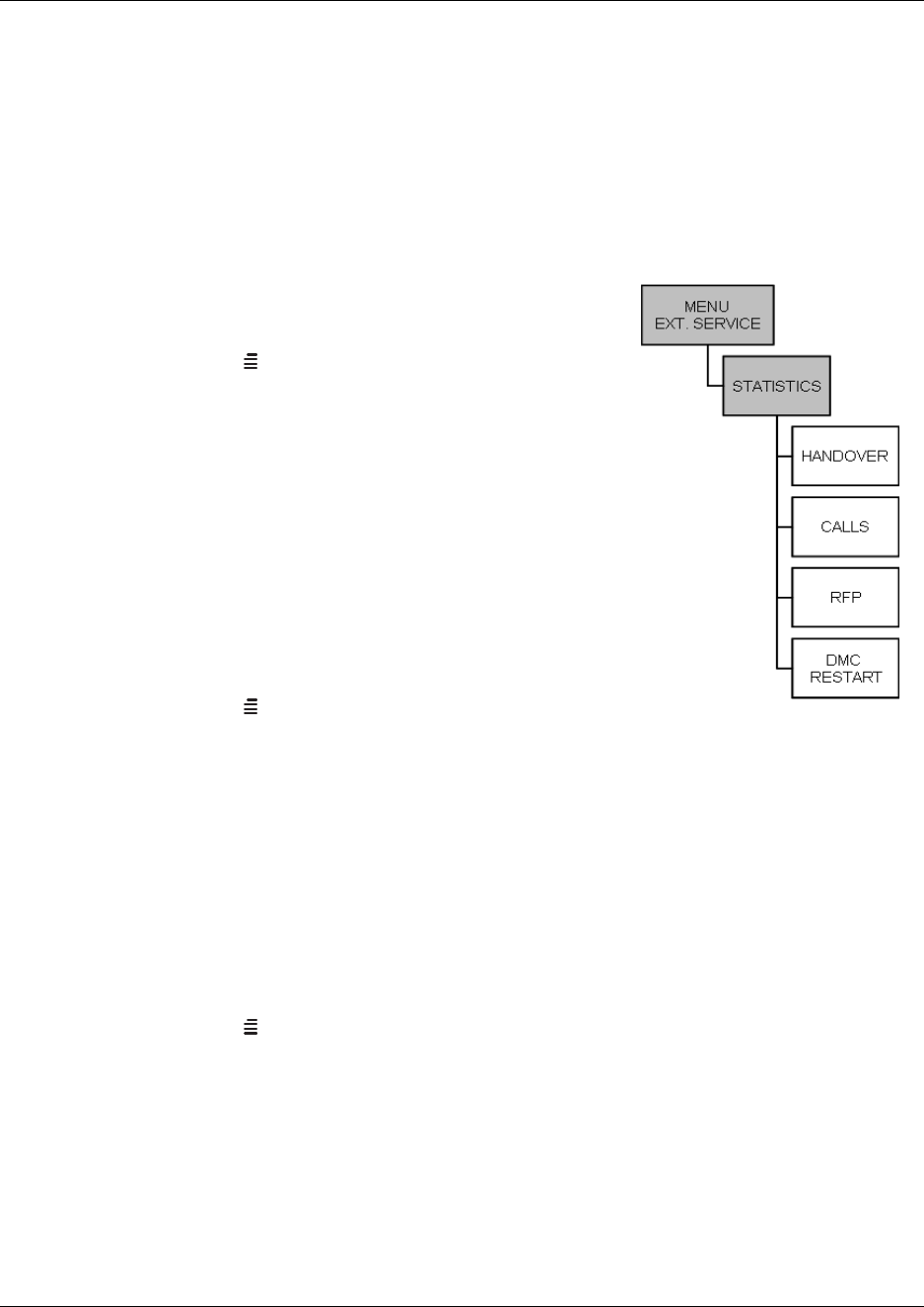
161
N0000623 01.5
Reading statistics from a Master handset
From the Master handset system a summary of statistics can be accessed on the following:
• handovers
• calls
• RFP (synchronizations and resets)
• DMC Restarts
Figure 105
Viewing handover statistics
1Press MENU () - go to EXT. SERVICE.
2Press 3OK - go to STATISTICS.
3Press 3OK - go to HANDOVER.
4Press 3OK
5The display will show base station number 1 with the
number of successful and failed handovers it has been
handling. Use the < > keys to access statistics on the other
base station.
Viewing call statistics
1Press MENU () - go to EXT. SERVICE.
2Press 3OK - go to STATISTICS.
3Press 3OK - go to CALLS.
4Press 3OK
5The display will show base station number 1 with the total number of calls that has based
through the base station and the number of busy calls. Use the < > keys to access statistics on
the other base station.
Viewing base station resets statistics
1Press MENU () - go to EXT. SERVICE.
2Press 3OK - go to STATISTICS.
3Press 3OK - go to RFP.
4Press 3OK
5The display will show base station number 1 with the total number of synchronizations and
resets of the selected base station. Use the < > keys to access statistics on the other base
station.
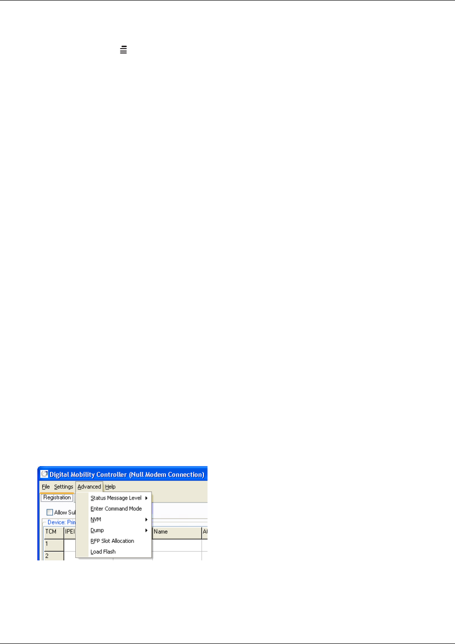
162
Viewing DMC restarts
1Press MENU () - go to EXT. SERVICE.
2Press 3OK - go to STATISTICS.
3Press 3OK - go to DMC RESTART.
4Press 3OK
5The display will show date and time of the last DMC restart. Use the < > keys to access
information on dates and times of the previous DMC restarts.
Advanced features
This section provides information about the advanced features in the:
•“DMC OAM program” on page 162
•“Digital Mobility Service Tool” on page 174
DMC OAM program
The Advanced menu in the DMC OAM program contains several commands used for debugging
the system. It also contains a command for downloading software to the system.
Note: Use advanced settings only under the direction of your authorized service representative.
This section contains a description of each of these commands:
•“Status Message Level” on page 162
•“Enter Command Mode” on page 163
•“NVM (non-volatile memory)” on page 164
•“Dump” on page 165
•“RFP Slot Allocation” on page 166
•“Load Flash (updating software)” on page 170
Status Message Level
For more information, refer to “Checking Status Information” on page 140.
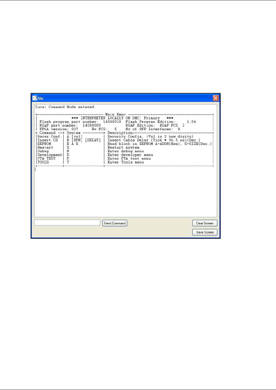
163
N0000623 01.5
Enter Command Mode
Entering command mode gives the user a terminal connection menu (a text menu) defined by the
DMC. In command mode it is possible to write text commands to the DMC and receive answers to
these commands.
1On the Advanced menu, click Enter Command Mode.
A Sio dialog box appears.
Figure 106
2Type a command, and then click Send Command to send it to the DMC.
The received answers from the DMC are displayed on the screen.
3To save the data on the screen, click Save Screen and save the text in a file.
This is useful if you need further support from trained technicians as you can now send the
data to them.
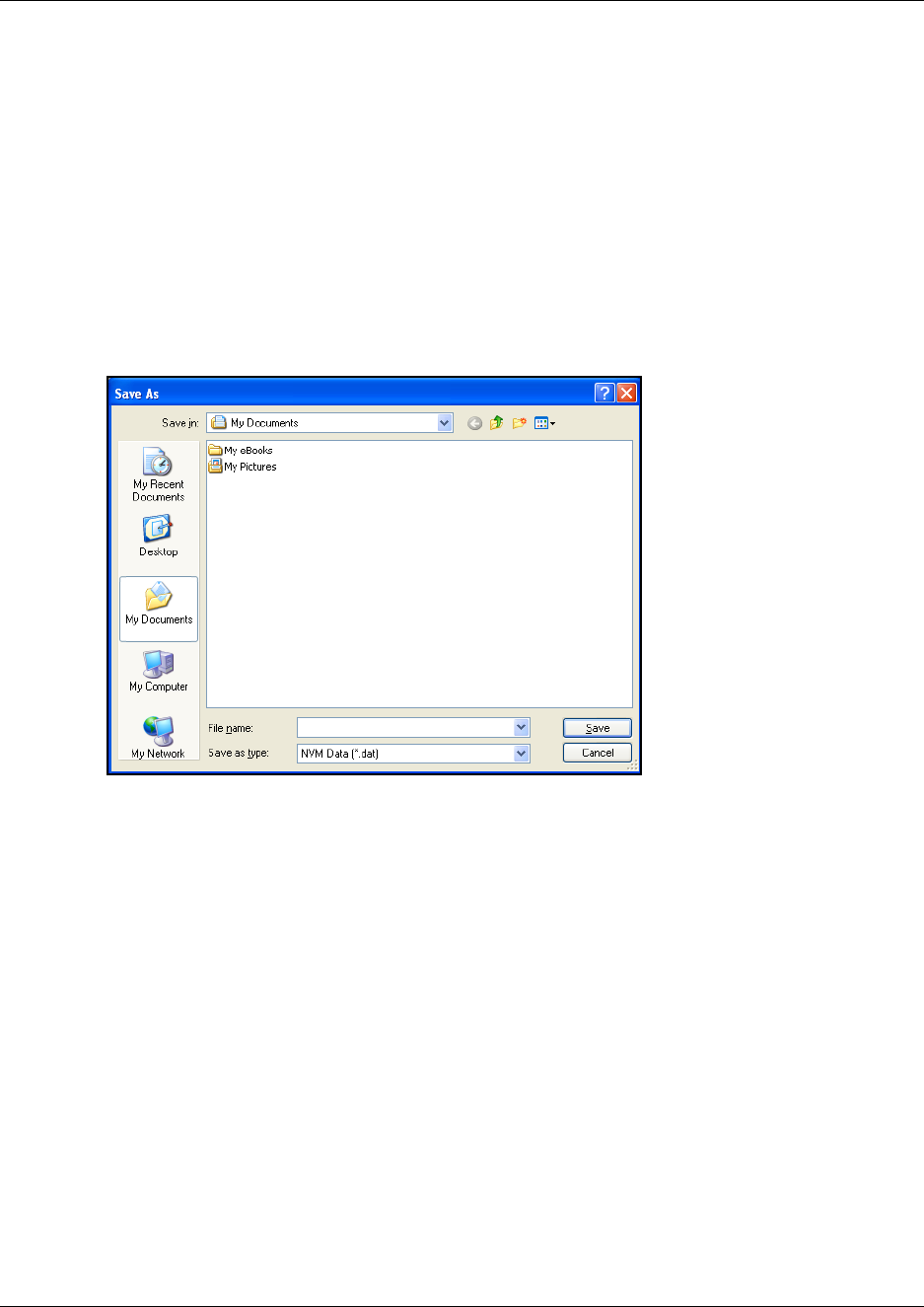
164
NVM (non-volatile memory)
Use this command to make a backup of non-volatile memory from the DMC (EEPROM data) or to
restore non-volatile memory. This is useful if you want to make a back up of your handset
registration data and load registration data from the backup file (a binary file *.dat).
Making a backup of NVM from the DMC
1On the Advanced menu, point to NVM, and then click Backup.
A Save As dialog box appears.
Figure 107
2Indicate in which folder and under what name the file should be saved, and then click Save.
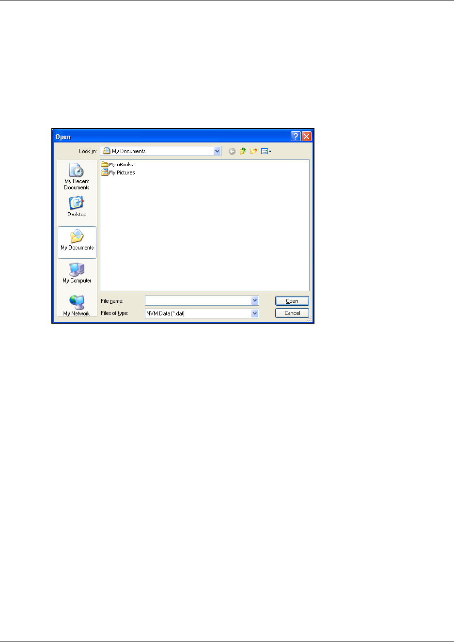
165
N0000623 01.5
Loading data from a backup file
Data, such as registration data, can be loaded into the system from a backup file.
1On the Advanced menu, point to NVM, and then click Restore.
An Open dialog box appears.
Figure 108
2Select the file in question, and then click Open. The registration data is loaded to the system.
Note: If you are loading data from a backup file from another DMC, then all handsets must be
resubscribed.
Dump
The Dump command is used for advanced debugging of the system. Use this command to log and
save files containing data from the DMC on your harddisk. You can also use the Dump command
to download a debug dump file from the DMC on your harddisk.
Note: Saving these files is only relevant if you have an agreement with your local service center.

166
How to log system data from the DMC
Before you start logging you can use the Status command (under Advanced/Dump/Log) to see
wether the log is running or not.
1On the Advanced menu, point to Dump, point to Log, and then click Start.
The log is started.
2On the Advanced menu, point to Dump, point to Log, and then click Stop to stop the log.
The log file is saved on the DMC.
3On the Advanced menu, point to Dump, point to Log, and then click Log Dump to copy the
log file from the DMC to your harddisk.
4When the log file is saved on your harddisk, you can send it to your local service center.
How to download a debug dump file from the DMC
If the DMC is restarted, the reason for the restart is saved internally on the DMC. To download the
file to your harddisk:
1On the Advanced menu, point to Dump, and then click Debug Dump.
The file is downloaded from the DMC to your harddisk.
2You can now send the file to your local service center.
RFP Slot Allocation
The RFP Slot Allocation command is used to read or change the tim slots of the connected base
stations (RFPs). This is useful if you want to change the default settings to avoid closely placed
base stations to interfer with each other.
Note: This does not apply to 2G4 installations.
Reading all RFP Slot Allocations
1On the Advanced menu, click RFP Slot Allocation.
A RFP Slot Allocation dialog box appears.
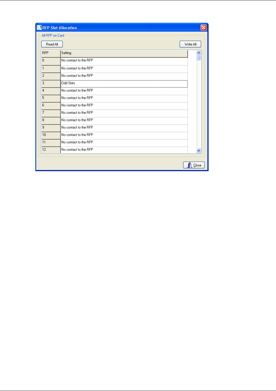
167
N0000623 01.5
Figure 109
2Click Read All.
A base station can have the RFP Slot Allocation setting: Even Slot, Odd Slot, or Follow RFP.
The default setting of a connected base station is Even Slot. If a base station is not connected,
then No contact to the RFP is displayed.
3Click Close.
Changing an RFP Slot Allocation for a single base station
1On the Advanced menu, click RFP Slot Allocation.
A RFP Slot Allocation dialog box appears.

168
Figure 110
2Alternate-click on the base station setting you want to change, and then select a new setting.
For example, if two base stations are located in a small room, one could be set to Even Slot
and the other to Odd Slot. This will avoid the two base stations to interfer with each other.
The Setting cell will be replaced by a status message.
3Click Read All if you want to see the selected RFP Slot Allocation setting.
4Click Close.
Changing RFP Slot Allocations for all base stations
1On the Advanced menu, click RFP Slot Allocation.
A RFP Slot Allocation dialog box appears.
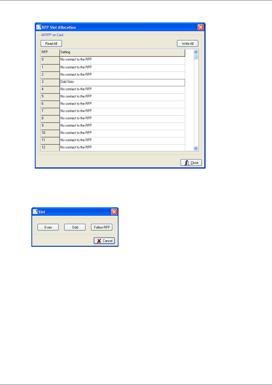
169
N0000623 01.5
Figure 111
2Click Write All., and then select a new setting for all the base stations.
A Slot dialog box appears.
Figure 112
3Select a new setting for all the base stations.
The Setting cells will be replaced by a status message.
4Click Read All if you want to see the selected RFP Slot Allocation setting.
5Click Close.

170
Load Flash (updating software)
The Load Flash command is used when the system software or base station software need to be
replaced by e.g. a new release or a software update.
Updating DMC software
To update the DMC software you load a flash to the system (Primary, Secondary or both). Contact
your distributor for newest software.
Note: A system can consist of two DMCs. In such a case, the first DMC is referred to as the
Primary DMC; the second, which is connected to the Primary DMC, is referred to as the
Secondary DMC. For more information about Primary and Secondary DMCs, refer to “Digital
Mobility Controller (DMC)” on page 29.
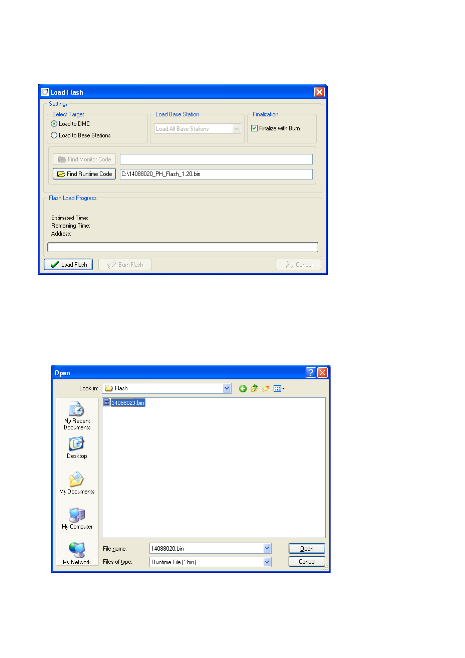
171
N0000623 01.5
1On the Advanced menu, click Load Flash.
A Load Flash dialog box appears.
Figure 113
2Under Select Target, click Load to DMC.
3Click Find Runtime Code.
An Open dialog box appears.
Figure 114
4Select the runtime code to be uploaded, and then click Open.
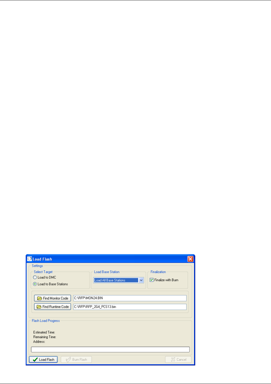
172
5You can burn the flash in two way:
Note: Burning the flash will set the system offline and the DMC is restarted after the burn
(this will have an impact on currently users).
• If you want to burn the flash immediately after the loading of the flash, select the Finalize
with Burn check box.
• You can also choose to burn the flash later, when no users will be disturbed by the system
going offline. This is done by clicking the Burn Flash button AFTER the flash has been
loaded to the system.
6Click Load Flash to load the flash to the system.
The flash is loaded to RAM, so that the system does not need to be offline when loading the
flash.
7After loading the flash, the flash is burned automatically if you have selected the Finalize with
Burn check box. Otherwise you can click on the Burn Flash button.
When the flash currently in RAM is written to the DMC flash the system will be offline.
After the burn, the DMC is restarted.
Note: If power failure occurs while burning the flash, the uploaded flash is corrupted and the
system cannot operate. Contact your authorized service representative for assistance.
Updating base station software
To update the base station software you load a flash to the system. Contact your distributor for
newest software.
1On the Advanced menu, click Load Flash.
A Load Flash dialog box appears.
Figure 115
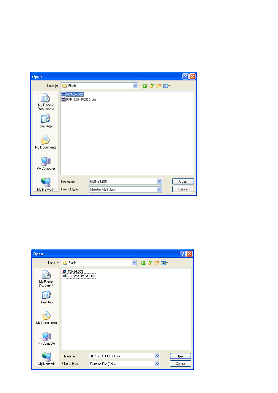
173
N0000623 01.5
2Under Select Target, click Load to Base Stations.
3Under Load Base Station, select a base station to download the software to.
4Click Find Monitor Code.
An Open dialog box appears.
Figure 116
5Select the monitor code to be uploaded, and then click Open.
6Click Find Runtime Code.
An Open dialog box appears.
Figure 117
7Select the runtime code to be uploaded, and then click Open.
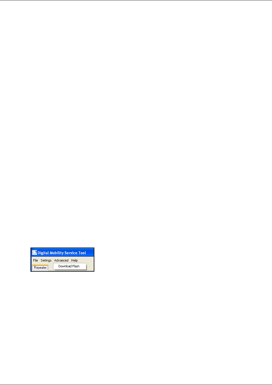
174
8You can burn the flash in two way:
Note: Burning the flash will set the system offline and the DMC is restarted after the burn
(this will have an impact on currently users).
• If you want to burn the flash immediately after the loading of the flash, select the Finalize
with Burn check box.
• You can also choose to burn the flash later, when no users will be disturbed by the system
going offline. This is done by clicking the Burn Flash button AFTER the flash has been
loaded to the system.
9Click Load Flash to load the flash to the system.
The flash is loaded to RAM, so that the system does not need to be offline when loading the
flash.
10 After loading the flash, the flash is burned automatically if you have selected the Finalize with
Burn check box. Otherwise you can click on the Burn Flash button.
When the flash currently in RAM is written to the DMC flash the system will be offline.
After the burn, the DMC is restarted.
Note: If power failure occurs while burning the flash, the uploaded flash is corrupted and the
system cannot operate. Contact your authorized service representative for assistance.
Digital Mobility Service Tool
The Advanced menu in the Digital Mobility Service Tool contains a Download Flash command
used for downloading new software to repeater or handset.
This section contains a description of:
•“Download Flash” on page 175
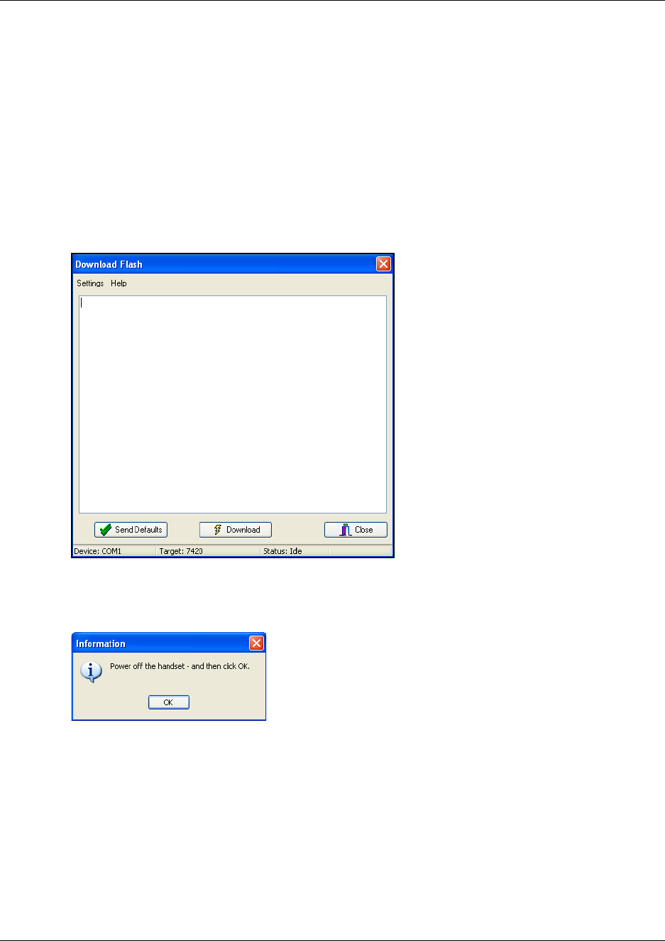
175
N0000623 01.5
Download Flash
1Before you start downloading flash to the repeater or handset, ensure that the repeater is
connected to the computer and the mains or that the programming stand or charger for the
handset is connected to the computer and that the handset is placed in the programming stand/
charger. Refer to “Set up of the hardware for repeater programming:” on page 74 or refer to
“Set up of the hardware for handset adjustment:” on page 142.
2On the Advanced menu, click Load Flash.
A Download Flash dialog box appears.
Figure 118
3Click Download.
4An information dialog box appears.
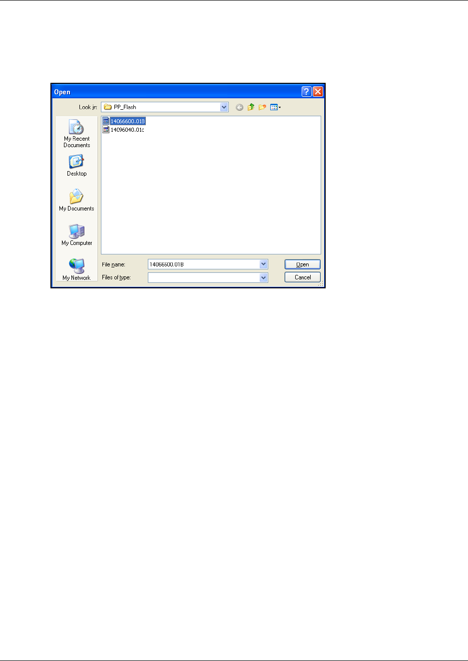
176
5Turn off the repeater or handset, and then click OK.
An Open dialog box appears.
Figure 119
6Select the file in question, and then click Open.
7If you are downloading software to a handset:
Turn the handset on:
• Press the handset Hook key + the keyboard ENTER key to start downloading the
software. Keep pressing the Hook key until the download is in progress (check the
messages on the screen).
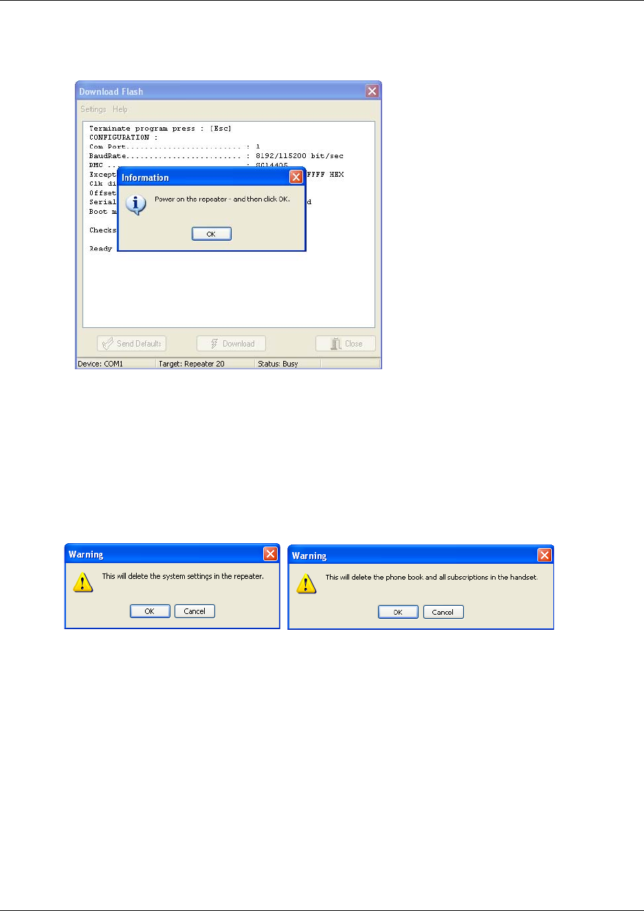
177
N0000623 01.5
8If you are downloading software to a repeater:
An information dialog box appears.
• Replace the adapter in the power supply, and then click OK.
The software is downloaded.
9A completion message displays on the screen when the download is completed.
10 Cycle the power of the repeater or handset.
11 Click Send Defaults.
A warning message appears.
12 Click OK to confirm.
The repeater or handset is now reset to factory defaults of the new software.
13 Click Close.
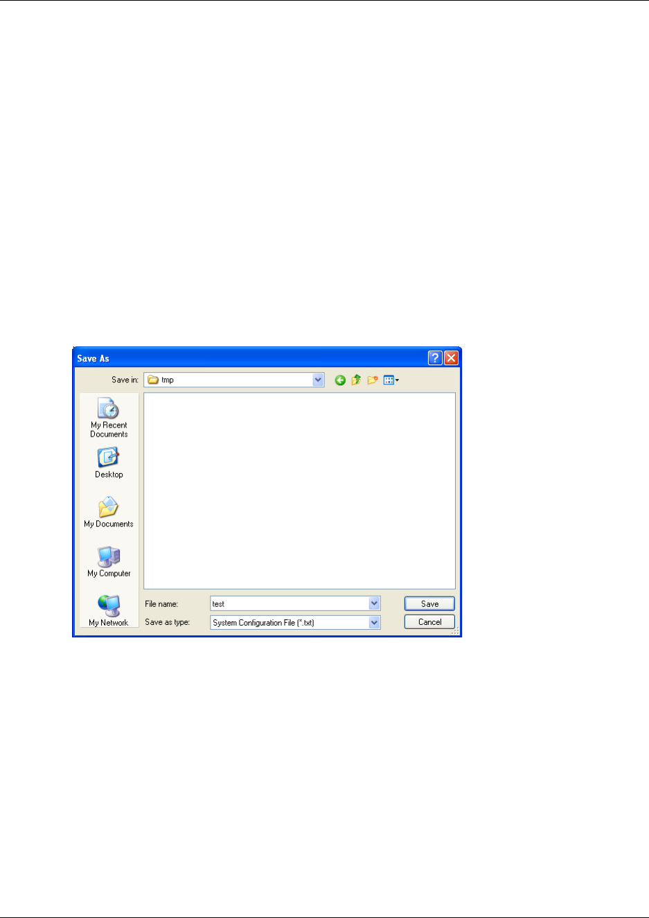
178
Saving configuration data
This section provides information about saving the configuration data of the DMC, registration
and subscription data of the handset and system information. When saving the configuration data
you have an overall overview of the DMC which is useful in case of problem solving. The
configuration data can be saved as a text file or a semicolon separated file.
This section contains the following information:
•“Save configuration data as a text file” on page 178
•“Save configuration data as semicolon separated file” on page 179
Save configuration data as a text file
1On the File menu, click Save Configuration as *.txt.
A Save as dialog box appears.
2Indicate in which folder and under what name the file should be saved, and then click Save.
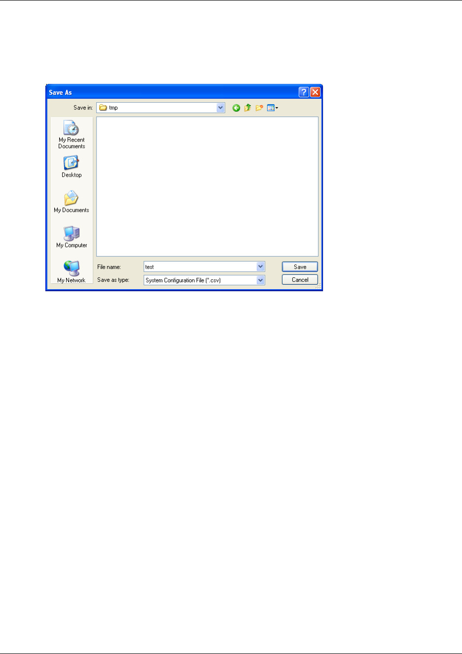
179
N0000623 01.5
Save configuration data as semicolon separated file
1On the File menu, click Save Configuration as *.csv.
A Save as dialog box appears.
2Indicate in which folder and under what name the file should be saved, and then click Save.

180
Troubleshooting error messages
This section provides you with general troubleshooting information about system problems and
error messages that may occur when working with the DMC OAM program or the Digital
Mobility Service Tool.
This section contains information about error messages in:
•“DMC OAM program” on page 180
•“Digital Mobility Service Tool” on page 181
DMC OAM program
The error messages that may occur in the DMC OAM program are described in the following
table.
Table 17
Problem Action required
NVM Restore Error Try to restore the NVM again or contact your local service center.
Both “Suppression
Activate Level” and
“Suppression” must set!
You need to set both values.
Select a valid serial device. Contact your system administrator.
Checksum Error
Flash Load Error
Illegal Request
Unknown Request
TCM is in use!
No user on TCM
IPEI must be 12 characters
long!!
The “Monitor” file could
not be found
The “Runtime” file could
not be found
Could not detect any serial
ports on the system

181
N0000623 01.5
Digital Mobility Service Tool
The error messages that may occur in the Digital Mobility Service Tool are described in the
following table.
Could not open COM?
Illegal Request - > Event: ?
Subevent: ? Cabability
State: ?
Incorrect password
Table 18
Problem Action required
Serial device unavailable! The chosen Com port does not exist. The Com port (e.g. USB Com port
converter) may have been removed - if so - connect the Com port again or
choose another valid Com port using the Connection Settings command.
The Com port is in use by another program. You can either shut down this
program or move the serial cable to another Com port, and then change to
this Com port using the Connection Settings command.
Check if the target is connected to the serial cable (e.g. handset is not
correctly placed in the charger) or if target is turned off. Check if the wrong
target has been chosen - if so - select the right target using the Connection
Settings command.
Check if the target is connected to the serial cable (e.g. handset is not
correctly placed in the charger) or if target is turned off. Check if the wrong
target has been chosen - if so - select the right target using the Connection
Settings command.
defaults.
The flash file could not be
found
Table 17
Problem Action required

182
Should you need to report a problem
Here is the minimal set of information required:
1Configuration data as obtained through Save Configuration command under File menu
2Floor plans showing location of base stations and repeaters
3Description of the issue: What happens? What was expected? Can it be reproduced? How?
How often?
Download failed (handset)
- handset cannot be turned
on
[00] MAIL_ERROR_IND ### MAIL ERROR[0001] ###
Download failed
[00] MAIL_ERROR_IND ### MAIL ERROR[0001] ###
Download failed
[00] CRP_ERROR_IND [File=338D34F4][Target=3002642A]
######### CRC32 ERROR #########
[00] STOP_PROGRAM_IND [Time 25086 msec]
Remove the repeater power cable from the mains, then replace it (or turn the
mains off and on). Download the flash again.
Error messages in Digital Mobility Service Tool (Continued)

Chapter 10 System Management
N0000623 01.5

Digital Mobility System Installation and Configuration Guide
184
Index
A
adjustment
handset 142
Advanced menu 162, 174
Allow Subscription check box 104
antenna, external 71
B
backup
non-volatile memory 164
base station
distances 80
installation 80, 81
positioning 81
synchronizing 105, 108
updating software 170
wiring 84
battery
charging 92
disposal 92
information 89
installing 90, 91
C
cable
IP modem 98
null-modem 97
Cable Delay Measurement command 105
Change Password command 102, 147
changing user settings
through DMC OAM program 131
through Master handset 132
command (Digital Mobility Service Tool)
Connection Settings 158
Download Flash 175
Exit 53
Command (DMC OAM)
PSTN Gain 154
command (DMC OAM)
Cable Delay Measurement 105
Change Password 102, 147
Date & Time 147
DSP Tone Level 156
Dump 165
Enter Command Mode 163
Exit 52
Load Flash 170
Measure Cable Delay 152
NVM 164
Restart DMC 153, 154, 156, 157
RFP PCS 148
RFP Slot Allocation 166
Save Configuration as *.csv 179
Save Configuration as *.txt 178
Start Status Message Log to File 141
Statistic 149
Status Message Level 162
Suppressiong Control 103
System Information 146
Voice Path Gain 153
communications configurations, editing 48
configuration data, saving 178
configuration tools
DMC OAM program 53
Master handset 58
configuring the DMC
through DMC OAM program 101
cable delay measurement 105
change password 102
subscription setting 104
suppression control 103
through Master handset 106
cable delay measurement 108
restart DMC 107
subscription setting 107
Connection Settings command 158
connection to DMC
direct connection 97
modem 101
remote connection 98
connectors
description of 33
placement 33
copyright 2
D
Date & Time command 147
Deployment 20
deregistration
through DMC OAM program 129
through Master handset 129
Digital Mobility Service Tool
description of 55

185
exiting 53
handset adjustment 143
starting 52
direct connection 97
DMC
configuring 101, 106
connecting a computer 97
equipment for installation 61
face plate 33
installation 60
power up 97
Primary 29
Secondary 29
system equipment 61
updating software 170
DMC OAM program
description of 53
exiting 52
starting 44
Download Flash command 175
DSP Tone Level command 156
Dump command 165
E
Enter Command Mode command 163
error messages 180
Exit command 52, 53
external antenna 71
F
File menu 52, 53
flash
burn 172, 174
load 170
H
handset
adjustment 142
deregistration 128
DN record settings 120
features 121
interoperability 120
line echo 153, 156
registration 110, 113
serial number 93
subscribe to different systems 119
system functions 124
unsubscription 128
updating software 174
voice path volume 153, 156
handset adjustment
Digital Mobility Service Tool 143
setup of hardware 142
Handset tab 143, 144
host system interoperability 120
I
install
base station 80
Digital Mobility Service Tool 44
DMC 60
in an equipment rack 62
on a flat surface 67
on the wall 64
DMC OAM program 44
external antenna 71
repeater 70
installation prerequisites 43
IP modem cable 98
L
line echo 153, 156
Load Flash command 170
M
Master handset
interface 58
menu structure 58
registering handsets 115
setting up 112, 114
Master handset interface
description of 58
Measure Cable Delay command 152
menu (Digital Mobility Service Tool)
Advanced 174
File 53
Settings 157
menu (DMC OAM)
Advanced 162
File 52
Settings 145
modem 101
MSF Demo tab 136
MSF Messages 136

186
N
null-modem cable 97, 98
NVM command 164
P
positioning
base station 81
PSTN Gain command 154
R
registration
through DMC OAM program 111
through Master handset 114
Registration tab 111
regulatory information 2
remote connection 98
repeater
external antenna 31
full slot 31
half slot 31
installation 70
programming 74, 75, 142
updating software 174
repeater programming 142
Digital Mobility Service Tool 75
hardware setup 74
programming kit 74
requirements 38
base station 40
Digital Mobility Service Tool 42
DMC 38
DMC OAM program 42
handset 42
repeater 40
Restart DMC command 153, 154, 156, 157
RFP PCS command 148
RFP Slot Allocation command 166
S
Save Configuration as *.csv command 179
Save Configuration as *.txt command 178
save configuration data 178
Settings menu 145, 157
software
updating 170, 175
Start Status Message Log to File command 141
Statistic 149
statistic
base station information 149
handset information 151
system information 152
Statistic command 149
status information 140
Status Message Level command 162
Status Message tab 140
subscribe
additional handsets 118
aditional Master handsets 118
to different systems 119
subscription setting
through DMC OAM program 104
through Master handset 107
Suppression Control command 103, 147
system
components of 29
diagram 28
system diagram 28
System Information command 146
system settings
in Digital Mobility Service Tool 157
in DMC OAM program 145
in Master handset 159
T
TCM loop connections 68
trademarks 2
troubleshooting
Digital Mobility Service Tool 181
DMC OAM program 180
U
unsubscription 128
V
Voice Path Gain command 153, 156
voice path volume 153, 156
