Avaya Ip Phones Configuration Guide Data Solutions
2015-06-01
: Avaya Avaya-Ip-Phones-Configuration-Guide-736614 avaya-ip-phones-configuration-guide-736614 avaya pdf
Open the PDF directly: View PDF ![]() .
.
Page Count: 394 [warning: Documents this large are best viewed by clicking the View PDF Link!]
- Figures
- 2.1 Reference Diagrams
- 2.2 Switch Software levels
- 2.3 Auto Configuration with a Stackable Ethernet Routing Switch – with traffic filters for QoS and optional LLDP MED Policy
- 2.3.1 Stackable Switch Configuration
- 2.3.1.1 Go to configuration mode.
- 2.3.1.2 Create VLAN’s
- 2.3.1.3 Add MLT
- 2.3.1.4 Enable VLACP on trunk members using recommend values
- 2.3.1.5 Discard Untagged Frames on uplink ports to SMLT Cluster
- 2.3.1.6 Configure Management IP address on switch
- 2.3.1.7 Configure PoE levels - Optional
- 2.3.1.8 QoS
- 2.3.1.9 Spanning Tree Configuration
- 2.3.1.10 Add LLDP-MED Network Policy – Optional for ERS 3500, ERS 4000 or ERS 5000
- 2.3.1.11 Enable IP Anti-Spoofing and IP Source Guard – Optional
- 2.3.2 Verify Operations
- 2.3.1 Stackable Switch Configuration
- 2.4 Auto Configuration with a Stackable Ethernet Routing Switch – with ADAC for QoS using LLDP Dectection
- 2.5 Auto Configuration with a Stackable Ethernet Routing Switch – with ADAC for QoS using MAC Address Dectection
- 2.6 Auto Configuration with an Ethernet Routing Switch 8300 using DHCP
- 2.6.1 ERS 8300 Configuration
- 2.6.1.1 Go to configuration mode.
- 2.6.1.2 Enable VLAN tagging on access port members
- 2.6.1.3 Create Data VLAN 61
- 2.6.1.4 Enable Spanning Tree Faststart on access port
- 2.6.1.5 Create Voice VLAN 220
- 2.6.1.6 Create Core VLAN 83
- 2.6.1.7 Configure access port members to untag the default VLAN
- 2.6.1.8 Enable RIP Globally
- 2.6.1.9 Enable DHCP relay agents
- 2.6.1.10 Enable IP Anti-Spoofing
- 2.6.1.11 Configure access port member PoE setting to high
- 2.6.2 Verify Operations
- 2.6.1 ERS 8300 Configuration
- 2.7 Auto Configuration with a Stackable Ethernet Routing Switch with EAP MHMA
- 2.8 Auto Configuration with a Stackable Ethernet Routing Switch using EAP with NEAP and User Based Policy
- 2.9 Auto Configuration with a Stackable Ethernet Routing Switch using EAP with Fail Open VLAN, Guest VLAN, and RADIUS Assigned VLAN for PC Supplicant
- 2.10 Avaya IP Phone – DHCP and Provisioning Files
- 2.11 Avaya Energy Saver (AES)
- 2.12 DHCP Server Setup
- 3.1 2000 Series IP Deskphones
- 3.2 1100 Series IP Deskphones
- 3.3 1200 Series IP Deskphone
- 3.4 Restore to Factory Defaults (applies to 1100-Series, 1200-Series, and 2007 IP Deskphones)
- 3.5 1600 Series IP Deskphones
- 3.6 9600 Series IP Deskphones
- 4.1 IP Office Script: Example using verbose mode
- 5.1 Voice VLAN
- 5.2 Auto Provisioning on Avaya IP Deskphones (1100-Series, 1200-Series, 2000-Series)
- VLAN-A:vvvv.
- Nortel-i2004-A,iii.iii.iii.iii:ppppp,aaa,rrr;iii.iii.iii.iii:ppppp,aaa,rrr.
- Where
- Nortel-i2004-B,param=value;param=value;param=value; …
- Where
- Nortel-i2004-B,s1=10.10.10.5;p1=4100;a1=1;r1=10;s2=10.10.10.10;p2=4100;a2=1;r2=10; menulock=p;pc=n;
- Nortel-i2004-B,cachedip=n;igarp=y;srtp=n;
- ADAC Port Restrictions
- Where:
- EDM
- Go to Device Physical View -> right-click port(s) and select Edit -> ADAC
- Where:
- LLDP defines
- LLDPDU
- IEEE 802.1 Organizational Specific TLV Set
- 5.5.6 TIA LLDP-MED Extensions
- 5.5.7 Vendor Specific 802.1AB (LLDP) TLVs
- 5.5.8 LLDP Support on Avaya Switches
- 5.5.9 LLDP Configuration on Avaya IP Phone Sets and Switches
- 5.5.10 LLDP VLAN Name
- 5.5.11 LLDP-MED (Media Endpoint Devices) Network Policy
- 5.5.11.1 LLDP-MED configuration on an Avaya Stackable Ethernet Routing Switch
- 5.5.11.2 Verifying Operations
- 5.5.11.3 LLDP-MED configuration on Stackable Ethernet Routing Switch without ADAC
- 5.5.11.4 LLDP Vendor Specific Avaya Configuration
- 5.5.11.5 Verify Operations
- 5.5.11.6 LLDP-MED configuration on the ERS8300
- 6.1 IP Deskphone Power Requirements
- 6.2 Avaya PoE Switches
- 6.3 Configuring PoE
- EDM:
- EDM:
- JDM - Port Level
- JDM – Port Level:
- JDM – Card Level:
- 8.1 Interface Roles – Stackable Ethernet Routing Switch
- 8.2 Default QoS Operations - ERS 8300
- 8.3 QoS Mapping
- 8.4 Queue Sets
- 8.5 Automatic QoS
- 8.6 Configuring QoS on a Avaya Switch for Voice Traffic
- 10.1 EAP Overview
- EAP Request and Response Code Types
- EAP and RADIUS related RFCs
- 10.2 EAP Support on Avaya IP Phone Sets
- 10.3 EAP and ADAC
- 10.4 EAP Support on Avaya Switches
- 10.5 EAP Feature Overview and Configuration on Avaya Stackable Switches
- 10.5.1 Single Host Single Authentication: SHSA
- 10.5.2 Guest VLAN
- 10.5.3 Multiple Host Multiple Authentication: MHMA
- 10.5.4 MHMA Radius Assigned VLANs
- 10.5.5 MHMA MultiVLAN
- 10.5.6 MHMA Last Assigned RADIUS VLAN
- 10.5.7 MHMA with Fail Open VLAN
- 10.5.8 VoIP VLAN
- 10.5.9 Multihost Dummy ADAC RADIUS Requests
- 10.5.10 Enhanced MHMA Feature: Non-EAP-MAC (NEAP)
- 10.5.11 Enhanced MHMA Feature: Non-EAP IP Phone client
- 10.5.12 EAP/NEAP with VLAN Names
- 10.5.13 Unicast EAP Request in MHMA
- 10.5.14 User Based Policies (UBP)
- 10.6 EAP Configuration using EDM
- 10.7 RADIUS Setup
- 11.1 Appendix A: IP Deskphone info Block (applies to the 2001, 2002, 2004, 2007, 1110, 1120E, 1140E, 1150E, 1165E, 1210, 1220, and 1230 IP Deskphones)
- 11.2 Appendix B: DHCP Configurable Parameters – Avaya 9600 Series H323 IP Phones
- 11.3 Appendix C: DHCP Configurable Parameters – Avaya 9600 Series SIP IP Phones
- 11.4 Appendix D: DHCP Configurable Parameters – Avaya 1600 Series H.323 IP Deskphones
- 11.5 Appendix E: DHCP Configurable Parameters – Avaya 1600 Series SIP IP Deskphones
- 11.6 Appendix F: 46xxsettings.txt Configuration File

Avaya IP Phones
Avaya Ethernet Routing Switches
Engineering
> Avaya IP Telephony Deployment
Technical Configuration Guide
Avaya Networking
Document Date: August 2012
Document Number: NN48500-517
Document Version: 7.4

Avaya Inc. – External Distribution
2
avaya.com
Aug 2012
© 2012 Avaya Inc.
All Rights Reserved.
Notices
While reasonable efforts have been made to ensure that the information in this document is complete and accurate at the time of
printing, Avaya assumes no liability for any errors. Avaya reserves the right to make changes and corrections to the information in
this document without the obligation to notify any person or organization of such changes.
Documentation disclaimer
Avaya shall not be responsible for any modifications, additions, or deletions to the original published version of this documentation
unless such modifications, additions, or deletions were performed by Avaya. End User agree to indemnify and hold harmless Avaya,
Avaya’s agents, servants and employees against all claims, lawsuits, demands and judgments arising out of, or in connection with,
subsequent modifications, additions or deletions to this documentation, to the extent made by End User.
Link disclaimer
Avaya is not responsible for the contents or reliability of any linked Web sites referenced within this site or documentation(s)
provided by Avaya. Avaya is not responsible for the accuracy of any information, statement or content provided on these sites and
does not necessarily endorse the products, services, or information described or offered within them. Avaya does not guarantee that
these links will work all the time and has no control over the availability of the linked pages.
Warranty
Avaya provides a limited warranty on this product. Refer to your sales agreement to establish the terms of the limited warranty. In
addition, Avaya’s standard warranty language, as well as information regarding support for this product, while under warranty, is
available to Avaya customers and other parties through the Avaya Support Web site: http://www.avaya.com/support
Please note that if you acquired the product from an authorized reseller, the warranty is provided to you by said reseller and not by Avaya.
Licenses
THE SOFTWARE LICENSE TERMS AVAILABLE ON THE AVAYA WEBSITE, HTTP://SUPPORT.AVAYA.COM/LICENSEINFO/
ARE APPLICABLE TO ANYONE WHO DOWNLOADS, USES AND/OR INSTALLS AVAYA SOFTWARE, PURCHASED FROM
AVAYA INC., ANY AVAYA AFFILIATE, OR AN AUTHORIZED AVAYA RESELLER (AS APPLICABLE) UNDER A COMMERCIAL
AGREEMENT WITH AVAYA OR AN AUTHORIZED AVAYA RESELLER. UNLESS OTHERWISE AGREED TO BY AVAYA IN
WRITING, AVAYA DOES NOT EXTEND THIS LICENSE IF THE SOFTWARE WAS OBTAINED FROM ANYONE OTHER THAN
AVAYA, AN AVAYA AFFILIATE OR AN AVAYA AUTHORIZED RESELLER, AND AVAYA RESERVES THE RIGHT TO TAKE
LEGAL ACTION AGAINST YOU AND ANYONE ELSE USING OR SELLING THE SOFTWARE WITHOUT A LICENSE. BY
INSTALLING, DOWNLOADING OR USING THE SOFTWARE, OR AUTHORIZING OTHERS TO DO SO, YOU, ON BEHALF OF
YOURSELF AND THE ENTITY FOR WHOM YOU ARE INSTALLING, DOWNLOADING OR USING THE SOFTWARE
(HEREINAFTER REFERRED TO INTERCHANGEABLY AS "YOU" AND "END USER"), AGREE TO THESE TERMS AND
CONDITIONS AND CREATE A BINDING CONTRACT BETWEEN YOU AND AVAYA INC. OR THE APPLICABLE AVAYA
AFFILIATE ("AVAYA").
Copyright
Except where expressly stated otherwise, no use should be made of the Documentation(s) and Product(s) provided by Avaya. All
content in this documentation(s) and the product(s) provided by Avaya including the selection, arrangement and design of the
content is owned either by Avaya or its licensors and is protected by copyright and other intellectual property laws including the sui
generis rights relating to the protection of databases. You may not modify, copy, reproduce, republish, upload, post, transmit or
distribute in any way any content, in whole or in part, including any code and software. Unauthorized reproduction, transmission,
dissemination, storage, and or use without the express written consent of Avaya can be a criminal, as well as a civil offense under
the applicable law.
Third Party Components
Certain software programs or portions thereof included in the Product may contain software distributed under third party agreements
("Third Party Components"), which may contain terms that expand or limit rights to use certain portions of the Product ("Third Party
Terms"). Information regarding distributed Linux OS source code (for those Products that have distributed the Linux OS source
code), and identifying the copyright holders of the Third Party Components and the Third Party Terms that apply to them is available
on the Avaya Support Web site: http://support.avaya.com/Copyright.
Trademarks
The trademarks, logos and service marks ("Marks") displayed in this site, the documentation(s) and product(s) provided by Avaya
are the registered or unregistered Marks of Avaya, its affiliates, or other third parties. Users are not permitted to use such Marks
without prior written consent from Avaya or such third party which may own the Mark. Nothing contained in this site, the
documentation(s) and product(s) should be construed as granting, by implication, estoppel, or otherwise, any license or right in and
to the Marks without the express written permission of Avaya or the applicable third party. Avaya is a registered trademark of Avaya
Inc. All non-Avaya trademarks are the property of their respective owners.
Downloading documents
For the most current versions of documentation, see the Avaya Support. Web site: http://www.avaya.com/support
Contact Avaya Support
Avaya provides a telephone number for you to use to report problems or to ask questions about your product. The support
telephone number is 1-800-242-2121 in the United States. For additional support telephone numbers, see the Avaya Web site:
http:// www.avaya.com/support.

Avaya Inc. – External Distribution
3
avaya.com
Aug 2012
Abstract
The purpose of this TCG is to review the many options available on Avaya Ethernet and Ethernet Routing
Switches for interoperability with Avaya’s IP Phone sets.
Acronym Key
Throughout this guide the following acronyms will be used:
AES :Avaya Energy Saver
ADAC :Auto Detect Auto Configuration
DHCP :Dynamic Host Configuration Protocol
DSCP : Differentiated Services Code Point
EAP :Extensible Authentication Protocol, IEEE 802.1X
EAP MHMA :EAP Multiple Host Multiple Authentication
EAP NEAP : non-EAP Client
EDM :Enterprise Device Manager
ERS :Ethernet Routing Switch
LACP :Link Aggregation Control Protocol
LLDP :Link Payer Discovery Protocol, IEEE 802.1AB
MLT :Multilink Trunking
PoE :Power over Ethernet
QoS :Quality of Service
SMLT :Split Multilink Trunking
TOS :Type of Service
UBP :User Based Policies
VLACP : Virtual LACP
VLAN : Virtual LAN
Avaya Inc. – External Distribution
4
avaya.com
Aug 2012
Revision Control
No
Date
Version
Revised By
Remarks
1
07/12/2007
2.2
ESE
Modification to section 4.4.2 on page 45.
2
01/28/2008
3.0
ESE
Modifications
3
02/14/2008
4.0
ESE
Added updates related to ADAC and
EAPOL.
Added ERS2500 and ERS4000 switches.
4
8/4/2009
6.0
JVE
Updates related to auto provisioning and
software updates on various switches
5
8/26/2010
7.0
JVE
Updated based on all Avaya IP Phones and
added features on various Avaya switches.
Added AES (Avaya Energy Savings)
6
1/07/2011
7.1
JVE
Update regarding LLDP-TLVs. LLDP tx-tlv
sys-cap added to interface level in section
2.3.1.1. This is required to support some IP
Phone models
7
2/21/2012
7.2
John Vant
Erve
Add details regarding voice-vlan
provisioning reflected in configuration
examples. Added ERS 4000 PoE+ models
8
7/30/2012
7.3
John Vant
Erve
Added ERS 3500.
8
8/21/2012
7.4
John Vant
Erve
Non-eap-phone support when using Avaya
9600 series IP Phones

Avaya Inc. – External Distribution
5
avaya.com
Aug 2012
Table of Contents
Figures ........................................................................................................................................................ 10
Tables .......................................................................................................................................................... 11
1. Overview ............................................................................................................................................. 13
2. Automatic Provisioning Configuration Examples ................................................................................ 14
2.1 Reference Diagrams ................................................................................................................... 15
2.1.1 Diagram 1 : Stackable Ethernet Routing Switch ..................................................................................... 15
2.1.3 Diagram 2 : Ethernet Routing Switch 8300 ............................................................................................ 16
2.2 Switch Software levels ................................................................................................................ 17
2.3 Auto Configuration with a Stackable Ethernet Routing Switch – with traffic filters for QoS and
optional LLDP MED Policy ...................................................................................................................... 18
2.3.1 Stackable Switch Configuration .............................................................................................................. 18
2.3.2 Verify Operations .................................................................................................................................... 25
2.4 Auto Configuration with a Stackable Ethernet Routing Switch – with ADAC for QoS using LLDP
Dectection ............................................................................................................................................... 32
2.4.1 Stackable Ethernet Switch Configuration ............................................................................................... 32
2.4.2 Verify operations .................................................................................................................................... 35
2.5 Auto Configuration with a Stackable Ethernet Routing Switch – with ADAC for QoS using MAC
Address Dectection ................................................................................................................................. 40
2.5.1 Stackable Ethernet Switch Configuration ............................................................................................... 40
2.5.2 Verify configuration ................................................................................................................................. 42
2.6 Auto Configuration with an Ethernet Routing Switch 8300 using DHCP .................................... 48
2.6.1 ERS 8300 Configuration ......................................................................................................................... 48
2.6.2 Verify Operations .................................................................................................................................... 54
2.7 Auto Configuration with a Stackable Ethernet Routing Switch with EAP MHMA ....................... 55
2.7.1 Stackable Switch Configuration .............................................................................................................. 55
2.7.2 Verify Operations .................................................................................................................................... 57
2.7.3 RADIUS Server Configuration ................................................................................................................ 60
2.8 Auto Configuration with a Stackable Ethernet Routing Switch using EAP with NEAP and User
Based Policy ............................................................................................................................................ 64
2.8.1 Stackable Switch Configuration .............................................................................................................. 65
2.8.2 Verify Operations .................................................................................................................................... 67
2.8.3 RADIUS Server – Policy Setup .............................................................................................................. 74
2.9 Auto Configuration with a Stackable Ethernet Routing Switch using EAP with Fail Open VLAN,
Guest VLAN, and RADIUS Assigned VLAN for PC Supplicant .............................................................. 81
2.9.1 Stackable Switch Configuration .............................................................................................................. 81
2.9.2 Verify Operations .................................................................................................................................... 84
2.10 Avaya IP Phone – DHCP and Provisioning Files ........................................................................ 89

Avaya Inc. – External Distribution
6
avaya.com
Aug 2012
2.10.1 DHCP Settings ................................................................................................................................... 89
2.10.2 Provisioning Files ............................................................................................................................... 90
2.11 Avaya Energy Saver (AES) ......................................................................................................... 92
2.11.1 Go to configuration mode. .................................................................................................................. 92
2.11.2 Add SNTP Server .............................................................................................................................. 92
2.11.3 Add Avaya Energy Saver configuration ............................................................................................. 92
2.11.4 Verify operations ................................................................................................................................ 93
2.12 DHCP Server Setup .................................................................................................................... 97
2.12.1 Windows 2003 DHCP Configuration .................................................................................................. 98
3. Avaya IP Deskphones ....................................................................................................................... 106
3.1 2000 Series IP Deskphones ...................................................................................................... 106
3.1.1 Feature Comparison ............................................................................................................................. 106
3.1.2 Accessing the Configuration Menu (2001/2002/2004) .......................................................................... 107
3.1.3 Configuration Menu on Phase II IP Phone 2001, Phase II IP Phone 2002 and Phase II IP Phone 2004
109
3.1.4 Accessing the Configuration Menu (2007 IP Deskphone) .................................................................... 111
3.1.5 Configuration Menu on the 2007 IP Deskphone ................................................................................... 111
3.2 1100 Series IP Deskphones ...................................................................................................... 114
3.2.1 Feature Comparison ............................................................................................................................. 114
3.2.2 Accessing the Configuration Menu ....................................................................................................... 115
3.2.3 Configuration Menu on the 1120E/1140E/1150E/1165E IP Deskphone .............................................. 116
3.3 1200 Series IP Deskphone ....................................................................................................... 119
3.3.1 Feature Comparison ............................................................................................................................. 119
3.3.2 Access the Configuration Menu ........................................................................................................... 120
3.3.3 Configuration Menu on IP Phone 12xx Series and IP Phone 1110 ...................................................... 121
3.4 Restore to Factory Defaults (applies to 1100-Series, 1200-Series, and 2007 IP Deskphones)
123
3.5 1600 Series IP Deskphones ...................................................................................................... 124
3.5.1 Feature Comparison ............................................................................................................................. 124
3.6 9600 Series IP Deskphones ...................................................................................................... 125
3.6.1 Feature Comparison ............................................................................................................................. 125
4. IP Office Script: ERS 3500 ................................................................................................................ 127
4.1 IP Office Script: Example using verbose mode ......................................................................... 128
5. Automatic Provisioning: Plug and Play IP Telephony ....................................................................... 130
5.1 Voice VLAN ............................................................................................................................... 131
5.2 Auto Provisioning on Avaya IP Deskphones (1100-Series, 1200-Series, 2000-Series)........... 132
5.2.1 Provisioning Server – Using TFTP/HTTP/HTTPS ................................................................................ 132
5.2.2 LLDP .................................................................................................................................................... 136

Avaya Inc. – External Distribution
7
avaya.com
Aug 2012
5.2.3 DHCP ................................................................................................................................................... 138
5.3 Auto Provisioning on Avaya IP Deskphones (1600-Series, 9600-Series) ................................ 141
5.3.1 LLDP .................................................................................................................................................... 141
5.3.2 DHCP ................................................................................................................................................... 145
5.3.3 Provisioning Server – Using HTTP or HTTPS ...................................................................................... 147
5.3.4 SNMP ................................................................................................................................................... 147
5.4 Auto Detection and Auto Configuration (ADAC) of Avaya IP Phones ...................................... 148
5.4.1 ADAC Operating Modes ....................................................................................................................... 148
5.4.2 QoS Settings ........................................................................................................................................ 150
5.4.3 ADAC Configuration ............................................................................................................................. 152
5.5 Link Layer Discovery Protocol (IEEE 802.1AB) ........................................................................ 156
5.5.1 Protocol Behavior ................................................................................................................................. 157
5.5.2 Mandatory TLVs ................................................................................................................................... 158
5.5.3 Optional TLVs....................................................................................................................................... 159
5.5.4 Basic Management TLVs ..................................................................................................................... 159
5.5.5 IEEE Organization Specific TLV ........................................................................................................... 159
5.5.6 TIA LLDP-MED Extensions .................................................................................................................. 162
5.5.7 Vendor Specific 802.1AB (LLDP) TLVs ................................................................................................ 163
5.5.8 LLDP Support on Avaya Switches........................................................................................................ 165
5.5.9 LLDP Configuration on Avaya IP Phone Sets and Switches ................................................................ 166
5.5.10 LLDP VLAN Name ........................................................................................................................... 166
5.5.11 LLDP-MED (Media Endpoint Devices) Network Policy .................................................................... 173
6. 802.3af and 802.3at (PoE+) Power over Ethernet ............................................................................ 186
6.1 IP Deskphone Power Requirements ......................................................................................... 187
6.2 Avaya PoE Switches ................................................................................................................. 189
6.3 Configuring PoE ........................................................................................................................ 198
6.3.1 Stackable Ethernet Routing Switch ...................................................................................................... 198
6.3.2 Ethernet Routing Switch 8300 .............................................................................................................. 204
7. Avaya Enery Saver ........................................................................................................................... 210
8. QoS ................................................................................................................................................... 211
8.1 Interface Roles – Stackable Ethernet Routing Switch .............................................................. 211
8.2 Default QoS Operations - ERS 8300 ........................................................................................ 212
8.3 QoS Mapping ............................................................................................................................ 213
8.4 Queue Sets ............................................................................................................................... 214
8.4.1 Ethernet Routing Switch 2500 .............................................................................................................. 214
8.4.3 Ethernet Routing Switch 3500 .............................................................................................................. 216
8.4.4 Ethernet Routing Switch 4000 .............................................................................................................. 218

Avaya Inc. – External Distribution
8
avaya.com
Aug 2012
8.4.5 Ethernet Routing Switch 5000 .............................................................................................................. 221
8.4.6 Ethernet Routing Switch 8300 .............................................................................................................. 223
8.5 Automatic QoS .......................................................................................................................... 226
8.5.1 Automatic QoS Edge Mode: Stackable Ethernet Routing Switch ......................................................... 227
8.5.2 Automatic QoS Configuration – Stackable Ethernet Routing Switch .................................................... 229
8.6 Configuring QoS on a Avaya Switch for Voice Traffic .............................................................. 230
8.6.1 Stackable Ethernet Routing Switch - Creating a new Interface Group of Trusted ................................ 230
8.6.2 Stackable Ethernet Routing Switch - Assuming default role combination with class of untrusted ........ 234
8.6.3 Configure L2 QoS on a Ethernet Routing Switch 8300 ........................................................................ 236
9. Anti-Spoofing Best Practices ............................................................................................................ 243
10. EAPoL Support ............................................................................................................................. 246
10.1 EAP Overview ........................................................................................................................... 246
10.2 EAP Support on Avaya IP Phone Sets ..................................................................................... 248
10.3 EAP and ADAC ......................................................................................................................... 249
10.4 EAP Support on Avaya Switches .............................................................................................. 250
10.5 EAP Feature Overview and Configuration on Avaya Stackable Switches ............................... 252
10.5.1 Single Host Single Authentication: SHSA ........................................................................................ 252
10.5.2 Guest VLAN ..................................................................................................................................... 252
10.5.3 Multiple Host Multiple Authentication: MHMA .................................................................................. 253
10.5.4 MHMA Radius Assigned VLANs ...................................................................................................... 253
10.5.5 MHMA MultiVLAN ............................................................................................................................ 254
10.5.6 MHMA Last Assigned RADIUS VLAN .............................................................................................. 255
10.5.7 MHMA with Fail Open VLAN ............................................................................................................ 255
10.5.8 VoIP VLAN ....................................................................................................................................... 255
10.5.9 Multihost Dummy ADAC RADIUS Requests .................................................................................... 256
10.5.10 Enhanced MHMA Feature: Non-EAP-MAC (NEAP) ........................................................................ 257
10.5.11 Enhanced MHMA Feature: Non-EAP IP Phone client ...................................................................... 258
10.5.12 EAP/NEAP with VLAN Names ......................................................................................................... 259
10.5.13 Unicast EAP Request in MHMA ....................................................................................................... 259
10.5.14 User Based Policies (UBP) .............................................................................................................. 260
10.6 EAP Configuration using EDM .................................................................................................. 262
10.7 RADIUS Setup .......................................................................................................................... 265
10.7.1 RADIUS Setup for NEAP ................................................................................................................. 265
10.7.2 RADIUS Setup for Dynamic VLAN Assignment ............................................................................... 274
10.7.3 IAS Server ....................................................................................................................................... 275
11. Appendixes.................................................................................................................................... 279
11.1 Appendix A: IP Deskphone info Block (applies to the 2001, 2002, 2004, 2007, 1110, 1120E,
1140E, 1150E, 1165E, 1210, 1220, and 1230 IP Deskphones) ........................................................... 279

Avaya Inc. – External Distribution
9
avaya.com
Aug 2012
11.2 Appendix B: DHCP Configurable Parameters – Avaya 9600 Series H323 IP Phones............. 289
11.3 Appendix C: DHCP Configurable Parameters – Avaya 9600 Series SIP IP Phones ............... 291
11.4 Appendix D: DHCP Configurable Parameters – Avaya 1600 Series H.323 IP Deskphones ... 293
11.5 Appendix E: DHCP Configurable Parameters – Avaya 1600 Series SIP IP Deskphones ....... 296
11.6 Appendix F: 46xxsettings.txt Configuration File ........................................................................ 298
12. Reference Documentation ............................................................................................................ 394

Avaya Inc. – External Distribution
10
avaya.com
Aug 2012
Figures
Figure 1: Base setup - Stackable Ethernet Routing Switch Setup.............................................................. 15
Figure 2: Base setup - Ethernet Routing Switch 8300 Setup ..................................................................... 16
Figure 3: IP Phone 2004 Access Configuration Menu ............................................................................. 107
Figure 4: IP Phone 2002 Access Configuration Menu ............................................................................. 107
Figure 5: IP Phone 2004 Power Cycle Phone Set ................................................................................... 108
Figure 6: IP Phone 2002 Power Cycle Phone Set ................................................................................... 108
Figure 7: IP Phone 2007 Phone Set ........................................................................................................ 111
Figure 8: 1100 Series IP Deskphone Setup ............................................................................................. 115
Figure 9: 1200 Series IP Deskphone Setup ............................................................................................. 120
Figure 10: IEEE 802.3 LLDP frame format ............................................................................................... 157
Figure 11: LLDPDU Frame Format ........................................................................................................... 158
Figure 12: Organizationally Specific TLV Format ..................................................................................... 159
Figure 13: LLDP-MED TLV Format ........................................................................................................... 162
Figure 14: Organizational TLV SubType 3 TLV Frame Format ................................................................ 166
Figure 15: LLDP-MED Network Policy TLV SubType 2 Frame Format .................................................... 173
Figure 16: PD and PSE 8-pin Modular Jack Pin’s ................................................................................... 186
Figure 17: Redundant Power Supply 15 (RPS15) .................................................................................... 196
Figure 18: EAP Overview ......................................................................................................................... 246
Figure 19: EAP Frame ............................................................................................................................. 247

Avaya Inc. – External Distribution
11
avaya.com
Aug 2012
Tables
Table 1: Avaya IP Deskphones – 2000 Series ........................................................................................ 106
Table 2: Avaya IP Deskphones – 1100 Series ........................................................................................ 114
Table 3: Avaya IP Phone Sets – 1200 series .......................................................................................... 119
Table 4: Avaya IP Phone Sets – 1600 series .......................................................................................... 124
Table 5: Avaya IP Phone Sets – 9600 series .......................................................................................... 126
Table 6: DHCP Response Codes ............................................................................................................ 138
Table 7: ADAC Support on Avaya Switches ............................................................................................. 155
Table 8: TLV Type Values......................................................................................................................... 158
Table 9: Organizational TLV ..................................................................................................................... 160
Table 10: LLDP MED TLV ......................................................................................................................... 162
Table 11: LLDP Support on Avaya Switches ............................................................................................ 165
Table 12: PSE Pinout Alternative ............................................................................................................. 186
Table 13: 802.3af PD Power Classification .............................................................................................. 187
Table 14: IP Deskphone Power Requirements ........................................................................................ 188
Table 15: ERS 8300 Power over Ethernet Options .................................................................................. 189
Table 16: ERS 5600 Power over Ethernet Options .................................................................................. 190
Table 17: ERS 5500 Power over Ethernet Options .................................................................................. 191
Table 18: ERS 4000 Power over Ethernet Options .................................................................................. 192
Table 19: ERS 4000 Power over Ethernet Plus Options .......................................................................... 193
Table 20: ERS 3500 Power over Ethernet Plus Options .......................................................................... 194
Table 21: ERS 2500 Power over Ethernet Options .................................................................................. 195
Table 22: RPS 15 Configuration Options .................................................................................................. 197
Table 23: Default QoS fields by class of interface—IPv4 only ................................................................. 212
Table 24: Avaya QoS Class Mappings .................................................................................................... 213
Table 25: Ethernet Routing Switch 4000 ASIC ......................................................................................... 220
Table 26: Ethernet Routing Switch 8300 Egress Queue ......................................................................... 223
Table 27: NT DSCP Mapping Values (Mixed) .......................................................................................... 227
Table 28: NT DSCP Values (Pure) ........................................................................................................... 227
Table 29: Default QOS Behavior for the Ethernet Routing Switch 8300 ................................................. 236
Table 30: MITM Attacks ............................................................................................................................ 244
Table 31: Anti-Spoofing support on Avaya Switches ................................................................................ 245
Table 32: EAP Support on Avaya IP Phones........................................................................................... 248
Table 33: EAP Support on Avaya Switches ............................................................................................. 251
Table 34: NEAP Passwords ..................................................................................................................... 257

Avaya Inc. – External Distribution
12
avaya.com
Aug 2012
Conventions
This section describes the text, image, and command conventions used in this document.
Symbols
Tip – Highlights a configuration or technical tip.
Note – Highlights important information to the reader.
Warning – Highlights important information about an action that may result in equipment
damage, configuration or data loss.
Text
Bold text indicates emphasis.
Italic text in a Courier New font indicates text the user must enter or select in a menu item, button or
command:
ERS5520-48T# show running-config
Output examples from Avaya devices are displayed in a Lucida Console font:
ERS5520-48T# show sys-info
Operation Mode: Switch
MAC Address: 00-12-83-93-B0-00
PoE Module FW: 6370.4
Reset Count: 83
Last Reset Type: Management Factory Reset
Power Status: Primary Power
Autotopology: Enabled
Pluggable Port 45: None
Pluggable Port 46: None
Pluggable Port 47: None
Pluggable Port 48: None
Base Unit Selection: Non-base unit using rear-panel switch
sysDescr: Ethernet Routing Switch 5520-48T-PWR
HW:02 FW:6.0.0.10 SW:v6.2.0.009
Mfg Date:12042004 HW Dev:H/W rev.02

Avaya Inc. – External Distribution
13
avaya.com
Aug 2012
1. Overview
This TCG covers standalone Avaya IP Phone sets and how they can be deployed on various Avaya
switches. It will cover features on Avaya switches related to VoIP with configuration examples. Overall,
topics that will be covered include the following:
Ethernet switch platforms that support PoE:
Ethernet Routing Switch 5000: 5520-48T-PWR, 5650TD-PWR, 5698TFD-PWR
Ethernet Routing Switch 4000: 4526T-PWR, 4550T-PWR, 4524GT-PWR, 4526GTX-PWR,
4548GT-PWR, 4526T-PWR+, 4550T-PWR+, 4826GTS-PWR+, 4850GTS-PWR+
Ethernet Routing Switch 3500: 3526T-PWR+, 3510GT-PWR+, 3526GT-PWR+
Ethernet Routing Switch 2500: 2526T-PWR, 2550T-PWR
Ethernet Routing Switch 8300
VoIP technologies:
Auto configuration via DHCP for VoIP Phone sets
Auto provisioning using tftp or http
Avaya Energy Saver (AES)
Authentication using EAPoL (802.1x)
Auto Detection Auto Configuration (ADAC)
Link Layer Discovery Protocol (LLDP)
Power over Ethernet (PoE)
Quality over Service (QoS)

Avaya Inc. – External Distribution
14
avaya.com
Aug 2012
2. Automatic Provisioning Configuration
Examples
This section will cover various configuration examples to allow for automatic or zero-touch provisioning of
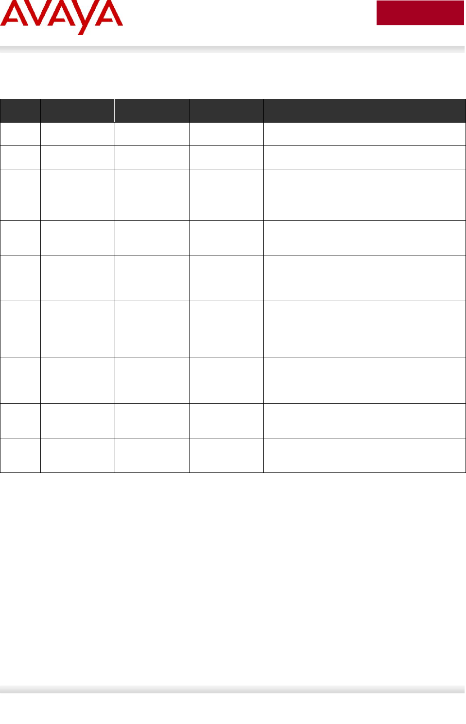
Avaya IP phones using Avaya data switches. The following chart summarizes each configuration
example.
Section
Item
QoS
Description
2.3
DHCP or
optional LLDP-
MED
Manually configured1
Switch uses either DHCP or optional LLDP-MED
Network Policy to provision voice VLAN
2.4
ADAC – LLDP
Dectection
Automatically applied
to Voice VLAN2
Switch uses ADAC to automically detect IP Phone
using LLDP
2.5
ADAC – MAC
Detection
Automatically applied
to Voice VLAN
Switch uses ADAC to automatically detect IP
Phone using MAC address of IP Phone
2.6
DHCP
None
Uses DHCP to get VLAN ID for voice VLAN from
data DHCP scope using the ERS 8300
2.7
EAP MHMA
N/A
Optional configuration to enable IP Phones as an
EAP Supplicant using MD5
2.8
EAP NEAP
N/A
Optional configuration using the EAP NEAP
feature on the switch allowing it to authenticate
the IP Phone using its MAC address
2.9
EAP fail open
VLAN, guest
VLAN, and
RADIUS
assigned VLAN
N/A
Optional configuration using the EAP non-eap-
phone feature and other EAP options such as fail
open VLAN, guest VLAN, and RADIUS assigned
VLANs
2.10
DHCP and
Provisioning
files
N/A
DHCP server settings and provisioning files for
the IP Phones used in this example
2.11
Avaya Energy
Saver
N/A
Optional configuration adding AES to the switch
2.12
DHCP Server
N/A
Windows 2003 DHCP server settings
1 QoS can be added in a number of methods such as simply trusting all traffic, applying filters, or enabling
Auto QoS (applies to Avaya 1100, 1200, or 2000 series only)
2 The LLDP-MED Network Policy can also set the QoS DSCP and p-bit priority values
Avaya Inc. – External Distribution
15
avaya.com
Aug 2012
2.1 Reference Diagrams
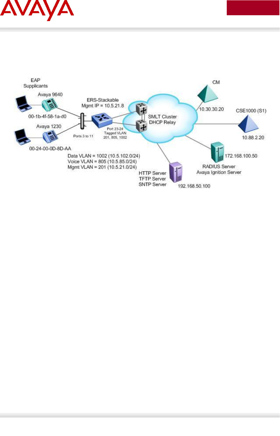
2.1.1 Diagram 1 : Stackable Ethernet Routing Switch
Figure 1: Base setup - Stackable Ethernet Routing Switch Setup
The following are the details for the base configuration:
ERS-Stackable is a stackable Ethernet Routing Switches (ERS 2500, 4000, or 5000 series) setup
as a Layer 2 switch connected to an SMLT Cluster
The SMLT Cluster requires that DHCP Relay be enabled with a DHCP Relay agent for both the
voice and data VLANs
Overall, we will configure the following
o Create Voice VLAN 805 with port members 3 to 11, 23, and 24
o Create Data VLAN 1002 with port members 3 to 11, 23, and 24
o Create Management VLAN 201 with port members 23 and 24
o Configure access ports 3 to 11 to allow untagged Data VLAN 1002 and tagged Voice
VLAN 805
o Configure core ports 23 and 24 using MLT 1 using VLAN tagging and with Spanning
disabled
o Use all the recommended SMLT best practices
Details regarding various Avaya IP Phone DHCP and provisioning file parameters are listed in
Appendix A

Avaya Inc. – External Distribution
16
avaya.com
Aug 2012
2.1.3 Diagram 2 : Ethernet Routing Switch 8300
Figure 2: Base setup - Ethernet Routing Switch 8300 Setup
Overall, we will configure the following:
Create Voice VLAN 220 with port members 1/1 to 1/25
Create Data VLAN 61 with port members 1/1 to 1/25
Create Trunk VLAN 83 with port member 5/5
Enable DHCP relay for VLAN 220 and 61
Enable Spanning Tree Fast-Start on ports 1/1 to 1/25 and disable STP on port 5/5
Configure all voice ports, 1/1 to 1/25, with POE priority of high
Enable RIP on all VLANs
By default, the ERS 8300 passes both the DSCP and p-bit values as-is. The p-bit value
determines the QoS level. For this example, we will not configure QoS as we are using VLAN
tagging for the Voice VLAN
Details regarding various Avaya IP Phone DHCP and provisioning file parameters are listed in
Appendix A
Avaya Inc. – External Distribution
17
avaya.com
Aug 2012
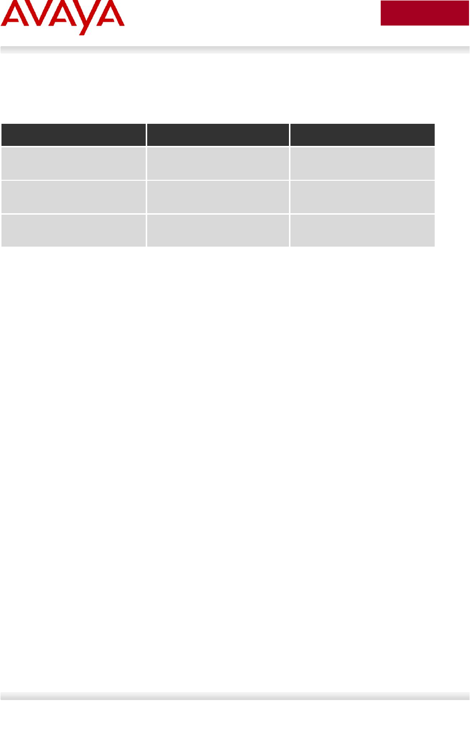
2.2 Switch Software levels
For this configuration example, the following software levels are used
Switch Model
Software Level
Notes
ERS 2500
4.4
Supports LLDP MED Policy via
ADAC
ERS 4000
5.6
Support LLDP MED Policy with
ADAC or without ADAC
ERS 5000
6.2.2.025
Support LLDP MED Policy with
ADAC or without ADAC
Avaya Inc. – External Distribution
18
avaya.com
Aug 2012
2.3 Auto Configuration with a Stackable Ethernet
Routing Switch – with traffic filters for QoS and
optional LLDP MED Policy
LLDP-MED Policy can be used with our without ADAC. If you choice to not use ADAC, by default, there
will be no QoS for the voice traffic. There are a number of ways to provide QoS for the voice traffic such
as:
Creating a new interface group with a class of trusted and applying this interface group to either
all ports or at minimum the uplink ports, call server ports, and all ports connected to IP phones.
This is simplest method, but, it also trusts all traffic which may or may not be acceptable
o Could create a filter to look for the data VLAN and remark to Standard service
Leave all ports with the default Interface Group with a class of untrusted and add a filter to look
for the voice VLAN and remark traffic to Premium service.
For this configuration example, we will simply create a traffic profile to match the voice VLAN and set the
CoS to Premium (p-bit value of 6 and DSCP value of 46).
This configuration example is in reference to diagram 1.
2.3.1 Stackable Switch Configuration
2.3.1.1 Go to configuration mode.
ERS-Stackable Step 1 - Enter configuration mode
ERS-Stackable>enable
ERS-Stackable#configure terminal
2.3.1.2 Create VLAN’s
ERS-Stackable Step 1 – Create VLAN’s 201, 805, and 1002
ERS-Stackable(config)#vlan create 201 name mgmt type port
ERS-Stackable(config)#vlan create 805 name voice type port voice-vlan
ERS-Stackable(config)#vlan create 1002 name data type port
ERS-Stackable Step 2 – Enable VLAN tagging on all appropriate ports
ERS-Stackable(config)#vlan port 23-24 tagging tagall
ERS-Stackable(config)#vlan port 3-11 tagging untagpvidOnly
ERS-Stackable Step 3 – Set VLAN configuration control to automatic and add VLAN port
members
ERS-Stackable(config)# vlan configcontrol automatic
Avaya Inc. – External Distribution
19
avaya.com
Aug 2012
ERS-Stackable(config)#vlan members add 201 23-24
ERS-Stackable(config)#vlan members add 1002 3-11,23-24
ERS-Stackable(config)#vlan members add 805 3-11,23-24
ERS-Stackable(config)#vlan port 3-11 pvid 1002
ERS-Stackable Step 4 – Remove port members from the default VLAN
ERS-Stackable(config)#vlan members remove 1 3-11,23-24
Voice VLAN integration has been added to the various ERS stackable switches
beginning with release 5.6 for the ERS 4000, and 6.2 for the ERS 5000. This feature
offers a unified concept of Voice VLAN though various applications including ADAC,
EAP, and LLDP. Please see section 5.1 for more details.
2.3.1.3 Add MLT
ERS5698TFD-1 Step 1 – Add MLT with trunk members
ERS-Stackable(config)# mlt 1 enable member 23,24 learning disable
2.3.1.4 Enable VLACP on trunk members using recommend values
ERS-Stackable Step 1 – Enable VLACP on uplink port member 23 and 24 using the
recommended VLACP MAC and timeout values
ERS-Stackable(config)#vlacp macaddress 01:80:c2:00:00:0f
ERS-Stackable(config)#vlacp enable
ERS-Stackable(config)#interface fastEthernet 23,24
ERS-Stackable(config-if)#vlacp timeout short
ERS-Stackable(config-if)#vlacp timeout-scale 5
ERS-Stackable(config-if)#vlacp enable
ERS-Stackable(config-if)#exit
2.3.1.5 Discard Untagged Frames on uplink ports to SMLT Cluster
ERS-Stackable: Step 1 – Enable Discard Untagged Frames
ERS-Stackable(config)#vlan ports 23-24 filter-untagged-frame enable
Avaya Inc. – External Distribution
20
avaya.com
Aug 2012
2.3.1.6 Configure Management IP address on switch
An IP address can be added in one of two ways. If the switch is strictly used as a Layer 2 switch, then an
IP address can be added via the Layer 2 method using the ACLI command ip address <switch|stack> <IP
address> netmask <mask> default-gateway <default GW>.
2.3.1.6.1 Adding Management IP - Layer 2
ERS-Stackable Step 1 – Set the IP address of the switch
ERS-Stackable(config)#vlan mgmt 201
ERS-Stackable(config)#ip address switch 10.5.21.8 netmask 255.255.255.0
default-gateway 10.5.21.1
2.3.1.6.2 Adding Management IP - Layer 3
ERS-Stackable Step 1 – Set the IP address of the switch
ERS-Stackable(config)#vlan mgmt 201
ERS-Stackable(config)#interface vlan 201
ERS-Stackable(config-if)#ip address 10.5.21.8 netmask 255.255.255.0
ERS-Stackable(config-if)#exit
ERS-Stackable Step 1 – Add the default route
ERS-Stackable(config)#ip routing
ERS-Stackable(config)#ip route 0.0.0.0 0.0.0.0 10.5.21.1 1
2.3.1.7 Configure PoE levels - Optional
If you wish, you can change the default PoE level of low to either high or critical.
ERS-Stackable Step 1 – Set PoE Power level high on all VoIP ports
ERS-Stackable(config)#interface fastEthernet 3-11
ERS-Stackable(config)#poe poe-priority high
ERS-Stackable(config)#exit

Avaya Inc. – External Distribution
21
avaya.com
Aug 2012
2.3.1.8 QoS
There are several options you can deploy to add QoS for the voice traffic.
Assign QoS class of trusted to all ports – easiest to implement and trust’s all traffic including soft
clients
Assign QoS class of trusted to all ports and adding a filter to remark the data traffic if you do not
trust traffic from the data VLAN – note, will will also remark soft clients to best effort
Set all access ports as untrusted (default setting), set uplink ports as trusted, and add a filter to
remark the voice traffic to CoS level of Premium – only provides QoS for the voice VLAN
Enable Auto QoS – only supported on limited Avaya products
o CS1000, CS2100, BCM, and/or SRG call servers
Enable ADAC – automatically provides QoS only to the voice VAN – please see next two sections
regarding ADAC provisioning
For this example, we will simply trust all traffic by setting all ports as trusted ports. This is the easiest
method for applying QoS for both untagged soft clients and tagged hard clients. We will also provision the
switch with queue set 4 providing 1 strict queue and 3 WRR queues which may be more acceptable to
handle voice, data, and video if the switch is either a ERS 4000 or ERS 5000; by default, the ERS 2500
uses queue set 4 while the ERS 4000 and ERS 5000 uses queue set 2. Otherwise, if the switch is only
supporting voice and data, you can use the default queue set 2 in reference to the ERS 4000 and ERS
5000.
If you are using an Avaya Ethernet Routing Switch 5000 or Ethernet Routing Switch
4000 (release 5.4 or higher), the default queue set (queue set 2) uses two strict queues
with large buffers. If you wish, you can provision another queue set if 2 queues do not
meet your needs. For example, queue set 4 which will provide three weighted queues
and one strict queue may be more acceptable to handle voice, video, and data. If you
do wish to use queue set 4, enter the ACLI command qos agent queue-set 4. You can
use the ACLI command show qos queue-set to view the make up for each queue set.
The ERS 2500 only supports one queue set, queue set 4, which supports one strict
queue and three weighted-round-robin (WWR) queues.
ERS-Stackable Step 1 – Change from default queue set (queue set 2) to queue set 4 and
reset the switch. Note, this only applies to the ERS 5000 or ERS 4000
ERS-Stackable(config)#qos agent queue-set 4
QoS queue setting isn't effective until after reset.
ERS-Stackable Step 2 – Create a new interface group with a class of trusted
ERS-Stackable(config)#qos if-group name trusted class trusted
ERS-Stackable(config)#qos if-assign port ALL name trusted
Avaya Inc. – External Distribution
22
avaya.com
Aug 2012
If you wish, you can provision the switch to remark the data traffic to best effort if you do not trust the
traffic from the data VLAN.
ERS-Stackable Step 1 – Traffic Profile Option. Configure either a traffic profile or ACL to
remark the data VLAN with a QoS level of Standard depending on switch model. Assuming
ERS-Stackable is an ERS 4000 or ERS 5000, it is recommend to use traffic profiles
ERS-Stackable(config)#qos traffic-profile classifier name one vlan-min 1002
vlan-max 1002 ethertype 0x800 update-dscp 0 update-1p 0
ERS-Stackable(config)#qos traffic-profile set port 1-13 name one
ERS-Stackable Step 1 – ACL Option. Configure either a traffic profile or ACL to remark the
data VLAN with a QoS level of Standard depending on switch model. ACL’s can be used
on a ERS 2500, ERS 4000, or ERS 5000 where it is recommended to use traffic profiles
over ACL’s if supported on the switch
ERS-Stackable(config)#qos l2-acl name one vlan-min 1002 vlan-max 1002 ethertype
0x800 update-dscp 0 update-1p 0
ERS-Stackable(config)#qos l2-acl name one ethertype 0x800 drop-action disable
ERS-Stackable(config)#qos acl-assign port 1-13 acl-type l2 name one
2.3.1.9 Spanning Tree Configuration
ERS-Stackable Step 1 – Enable STP Fast-Start and BPDU filtering on port 3 to 11
ERS-Stackable(config)#interface fastEthernet all
ERS-Stackable(config-if)#spanning-tree port 3-11 learning fast
ERS-Stackable(config-if)#spanning-tree port 3-11 bpdu-filtering timeout 0
ERS-Stackable(config-if)#spanning-tree port 3-11 bpdu-filtering enable
2.3.1.10 Add LLDP-MED Network Policy – Optional for ERS 3500, ERS
4000 or ERS 5000
As an option, you can enable LLDP-MED with Network Policy to provision the voice VLAN without having
to use DHCP. In addition, you can also provision LLDP vendor specific settings to provision the call
server and file server (only for the Avaya 96xx IP phones as per this configuration example).
Note that the ERS 2500 requires ADAC must be used to enable LLDP MED. The ERS 3500 requires
software release 5.0.1 or higher to use LLDP-MED without ADAC.
ERS-Stackable Step 1 – Add LLDP MED Network Policy
ERS-Stackable(config)#interface fastEthernet 3-11
ERS-Stackable(config-if)#lldp med-network-policies voice tagging tagged vlan-id
805
ERS-Stackable(config-if)#exit

Avaya Inc. – External Distribution
23
avaya.com
Aug 2012
2.3.1.10.1 LLDP Tx-TLVs – Older Software Releases
Depending on the software release used, it may be nessessary to enable LLDP TLVs. This does not
apply to the ERS 4000 as of release 5.5, ERS 3500 as of release 5.0.1, and ERS 5000 as of release 6.3
from a factory default setting, but, to verify if the TLVs are enabled or not, please enter the ACLI
commands show lldp port 3-11 & show lldp tx-tlv.
ERS-Stackable Step 1 – Enable LLDP TLVs
ERS-Stackable(config)#interface fastEthernet 3-11
ERS-Stackable(config-if)#lldp tx-tlv local-mgmt-addr port-desc sys-cap sys-desc
sys-name
ERS-Stackable(config-if)#lldp status txandRx config-notification
ERS-Stackable(config-if)#lldp tx-tlv med extendedPSE inventory location med-
capabilities network-policy
ERS-Stackable(config-if)#exit
2.3.1.10.2 Enable LLDP Vendor Specific settings
Up to 8 call-servers and up to 4 file-servers can be defined. Note that, for this configuration example, the
LLDP vendor specific settings only apply to the Avaya IP Phones.
ERS-Stackable Step 1 – Add LLDP Vendor Specific options
ERS-Stackable(config)#lldp vendor-specific avaya call-server 1 10.30.30.20
ERS-Stackable(config)#lldp vendor-specific avaya file-server 1 192.168.50.100
ERS-Stackable(config)#interface fastEthernet 3-11
ERS-Stackable(config)#lldp vendor-specific avaya dot1q-framing tagged
ERS-Stackable(config)#exit
2.3.1.11 Enable IP Anti-Spoofing and IP Source Guard – Optional
To prevent IP spoofing attacks, it is recommended to enabled IP DHCP Snooping and IP Arp Inspection.
In addition, it is recommended to enabled IP Source Guard which prevents a host from spoofing a source
IP other than that assigned by DHCP.
ERS-Stackable Step 1 – Enable IP DHCP Snooping for voice VLAN 805 and data VLAN
1002
ERS-Stackable(config)#ip dhcp-snooping vlan 805
ERS-Stackable(config)#ip dhcp-snooping vlan 1002
ERS-Stackable(config)#ip dhcp-snooping enable
ERS-Stackable Step 2 – Enable IP Arp Inspection for voice VLAN 805 and data VLAN 1002
ERS-Stackable(config)#ip arp-inspection vlan 805

Avaya Inc. – External Distribution
24
avaya.com
Aug 2012
ERS-Stackable(config)#ip arp-inspection vlan 1002
ERS-Stackable Step 3 – Enable core ports 23 and 24 as a trusted port
ERS-Stackable(config)#interface fastEthernet 23-24
ERS-Stackable(config-if)#ip dhcp-snooping trusted
ERS-Stackable(config-if)#ip arp-inspection trusted
ERS-Stackable(config-if)#exit
ERS-Stackable Step 4 – Enable IP Source Guard on access ports 3 to 11
ERS-Stackable(config)#interface fastEthernet 3-11
ERS-Stackable(config-if)#ip verify source
ERS-Stackable(config-if)#exit
Avaya Inc. – External Distribution
25
avaya.com
Aug 2012
2.3.2 Verify Operations
Via the ERS-Stackable switch, verify the following information:
Step 1 – Verify VLAN Configuration as shown for ERS-Stackable where the default VLAN
should be VLAN 1002 on ports 3 to 11
ERS-Stackable#show vlan interface info 3-11
Result:
Filter Filter
Untagged Unregistered
Port Frames Frames PVID PRI Tagging Name
---- -------- ------------ ---- --- ------------- --------------
3 No Yes 1002 0 UntagPvidOnly Port 3
4 No Yes 1002 0 UntagPvidOnly Port 4
5 No Yes 1002 0 UntagPvidOnly Port 5
6 No Yes 1002 0 UntagPvidOnly Port 6
7 No Yes 1002 0 UntagPvidOnly Port 7
8 No Yes 1002 0 UntagPvidOnly Port 8
9 No Yes 1002 0 UntagPvidOnly Port 9
10 No Yes 1002 0 UntagPvidOnly Port 10
11 No Yes 1002 0 UntagPvidOnly Port 11
Step 2 – Verify VLAN Configuration as shown for ERS-Stackable where the ports 3 to 11
should be members of untagged VLAN 1002 and tagged VLAN 805
ERS-Stackable#show vlan interface vids 3-11
Result:
Port VLAN VLAN Name VLAN VLAN Name VLAN VLAN Name
---- ---- ---------------- ---- ---------------- ---- ----------------
3 805 voice 1002 data
---- ---- ---------------- ---- ---------------- ---- ----------------
4 805 voice 1002 data
---- ---- ---------------- ---- ---------------- ---- ----------------
5 805 voice 1002 data
---- ---- ---------------- ---- ---------------- ---- ----------------
6 805 voice 1002 data
---- ---- ---------------- ---- ---------------- ---- ----------------
7 805 voice 1002 data

Avaya Inc. – External Distribution
26
avaya.com
Aug 2012
---- ---- ---------------- ---- ---------------- ---- ----------------
8 805 voice 1002 data
---- ---- ---------------- ---- ---------------- ---- ----------------
9 805 voice 1002 data
---- ---- ---------------- ---- ---------------- ---- ----------------
10 805 voice 1002 data
---- ---- ---------------- ---- ---------------- ---- ----------------
11 805 voice 1002 data
---- ---- ---------------- ---- ---------------- ---- ----------------
Step 3 – Verify IP Phone detection by issuing PoE port status command
ERS-Stackable#show poe-port-status 3-11
Result:
Admin Current Limit
Port Status Status Classification (Watts) Priority
---- ------- ----------------- -------------- ------- --------
3 Enable Detecting 0 16 Low
4 Enable Detecting 0 16 Low
5 Enable Detecting 0 16 Low
6 Enable Detecting 0 16 Low
7 Enable Delivering Power 2 16 Low
8 Enable Detecting 0 16 Low
9 Enable Delivering Power 2 16 Low
10 Enable Delivering Power 2 16 Low
11 Enable Detecting 0 16 Low
Step 4 – Verify IP Phone power usage by issuing PoE power measured command
ERS-Stackable#show poe-power-measurement 3-11
Result:
Port Volt(V) Current(mA) Power(Watt)
---- ------- ----------- ---------------
3 0.0 0 0.000
4 0.0 0 0.000
5 0.0 0 0.000
6 0.0 0 0.000
7 48.4 58 2.807
8 0.0 0 0.000

Avaya Inc. – External Distribution
27
avaya.com
Aug 2012
9 48.4 61 2.952
10 48.4 58 2.807
11 0.0 0 0.000
Step 5 – Verify LLDP configuration.
ERS-Stackable#show running-config module 802.1ab
Result for ERS 4000 and ERS 5000 where the items highlighted in blue will not be shown
via the ERS 4000 as these are the default settings:
! Displaying only parameters different to default
!================================================
enable
configure terminal
!
! *** 802.1ab ***
!
!
! *** 802.1ab vendor-specific Avaya TLVs config ***
!
lldp vendor-specific avaya call-server 1 10.30.30.20
lldp vendor-specific avaya file-server 1 192.168.50.100
interface FastEthernet ALL
lldp port 1/3-11 vendor-specific avaya dot1q-framing tagged
exit
!
interface FastEthernet ALL
lldp port 3-11 config-notification
lldp tx-tlv port 3-11 local-mgmt-addr port-desc sys-desc sys-name
lldp tx-tlv port 3-11 med extendedPSE inventory location med-capabilities
network-policy
exit
!
! *** 802.1AB MED Voice Network Policies ***
!
interface FastEthernet ALL
lldp med-network-policies port 3-11 voice dscp 46 priority 6 tagging tagged vla
n-id 805
exit

Avaya Inc. – External Distribution
28
avaya.com
Aug 2012
Result for ERS 2500:
!
! *** 802.1ab ***
!
! *** 802.1ab vendor-specific Avaya TLVs config ***
!
lldp vendor-specific avaya call-server 1 10.30.30.20
lldp vendor-specific avaya file-server 1 192.168.50.100
interface FastEthernet ALL
lldp port 1/3-11,1/13 vendor-specific avaya dot1q-framing tagged
exit
Step 2 – Verify LLDP network policy configuration – note, this only applies to the ERS 4000
or ERS 5000 as this command is not available on the ERS 2500
ERS-Stackable#show lldp med-network-policies port 3-11
or, via some switches
ERS-Stackable#show lldp med-network-policies port 3-11 voice
Result:
-------------------------------------------------------------------------------
LLDP-MED network-policies
-------------------------------------------------------------------------------
-------------------------------------------------------------------------------
Unit/ Application Type VlanID Tagging DSCP Priority
Port
-------------------------------------------------------------------------------
3 Voice 805 tagged 46 6
4 Voice 805 tagged 46 6
5 Voice 805 tagged 46 6
6 Voice 805 tagged 46 6
7 Voice 805 tagged 46 6
8 Voice 805 tagged 46 6
9 Voice 805 tagged 46 6
10 Voice 805 tagged 46 6
11 Voice 805 tagged 46 6
-------------------------------------------------------------------------------

Avaya Inc. – External Distribution
29
avaya.com
Aug 2012
Step 3 – Verify LLDP MED configuration; for example, the following ACLI command shows
LLDP MED configuration for port 11
ERS-Stackable#show lldp port 13 local-sys-data med
Result:
-------------------------------------------------------------------------------
lldp local-sys-data chassis
-------------------------------------------------------------------------------
-------------------------------------------------------------------------------
ChassisId: MAC address 00:13:0a:35:e8:00
SysName: ERS-Stackable
SysCap: rB / rB (Supported/Enabled)
SysDescr:
Ethernet Routing Switch ERS-Stackable HW:05 FW:6.0.0.10 SW:v6.2.0.009
MED-Device class: Network Connectivity Device
MED-POE Device Type: PSE Device
HWRev: 05 SerialNumber: SDNI2S00L9
FWRev: 6.0.0.10 SWRev: v6.2.0.009
ManufName: Avaya ModelName: ERS-Stackable
-------------------------------------------------------------------------------
lldp local-sys-data port
-------------------------------------------------------------------------------
Port: 11
MED-Capabilities: CNLSI
MED-PSE PDPort Priority: Low Power Value: 16.0 Watt
MED-Application Type: Voice VLAN ID: 805
L2 Priority: 6 DSCP Value: 46 Tagged Vlan, Policy defined
-------------------------------------------------------------------------------
Sys capability: O-Other; R-Repeater; B-Bridge; W-WLAN accesspoint; r-Router;
T-Telephone; D-DOCSIS cable device; S-Station only.
Med Capabilities-C: N-Network Policy; L-Location Identification; I-Inventory;
S-Extended Power via MDI - PSE; D-Extended Power via MDI - PD.

Avaya Inc. – External Distribution
30
avaya.com
Aug 2012
Step 4 – Verify LLDP neighbor details assuming an Avaya 9640G is connected to port 11
ERS-Stackable# show lldp port 11 neighbor detail
Result:
-------------------------------------------------------------------------------
lldp neighbor
-------------------------------------------------------------------------------
Port: 11 Index: 89 Time: 11 days, 04:49:49
ChassisId: Network address IPv4 10.1.90.222
PortId: MAC address 00:1b:4f:58:1a:d0
SysName: AVB581AD0
SysCap: TB / TB (Supported/Enabled)
PVID: PPVID Supported: none
VLAN Name List: none PPVID Enabled: none
Dot3-MAC/PHY Auto-neg: supported/enabled OperMAUtype: 100BaseTXFD
PMD auto-neg: 10Base(T, TFD), 100Base(TX, TXFD), 1000Base(TFD)
MED-Capabilities: CNDI / CNDI (Supported/Current)
MED-Device type: Endpoint Class 3
MED-Application Type: Voice VLAN ID: 805
L2 Priority: 6 DSCP Value: 46 Tagged Vlan, Policy defined
Med-Power Type: PD Device Power Source: FromPSE
Power Priority: Low Power Value: 5.6 Watt
HWRev: 9640GD01A FWRev: hb96xxua3_11.bin
SWRev: ha96xxua3_11.bin SerialNumber: 10N520301110
ManufName: Avaya ModelName: 9640G
AssetID:
-------------------------------------------------------------------------------
Sys capability: O-Other; R-Repeater; B-Bridge; W-WLAN accesspoint; r-Router;
T-Telephone; D-DOCSIS cable device; S-Station only.
Total neighbors: 3
Med Capabilities-C: N-Network Policy; L-Location Identification; I-Inventory;
S-Extended Power via MDI - PSE; D-Extended Power via MDI - PD.

Avaya Inc. – External Distribution
31
avaya.com
Aug 2012
Step 5 – Verify LLDP neighbor vendor-specific Avaya IP Phones
ERS-Stackable# show lldp neighbor vendor-specific avaya phone-ip
Result:
------------------------------------------------------------------------------
Neighbors LLDP info - Avaya TLVs
------------------------------------------------------------------------------
------------------------------------------------------------------------------
Port: 7
Avaya Phone IP:
Address: 10.1.90.221
Netmask: 255.255.255.0
Gateway: 10.1.90.1
Port: 11
Avaya Phone IP:
Address: 10.1.90.222
Netmask: 255.255.255.0
Gateway: 10.1.90.1
Avaya Inc. – External Distribution
32
avaya.com
Aug 2012
2.4 Auto Configuration with a Stackable Ethernet
Routing Switch – with ADAC for QoS using LLDP
Dectection
The following configuration example covers setting up a network to support both voice and data to
support Auto-Configuration with Avaya’s stackable Ethernet Routing switches and IP Phone sets. ADAC
LLDP-MED detection will be enabled detect the IP Phone and apply QoS.
This configuration example is in reference to diagram 1 and base configuration in section 2.3.
2.4.1 Stackable Ethernet Switch Configuration
Please note, the ADAC configuration is exactly the same as that used in section 2.3 with the only
difference that ADAC is used to automatically detect the IP Phone via LLDP and provide QoS.
2.4.1.1 Enable ADAC Globally
ERS-Stackable Step 1
ERS-Stackable(config)#interterface fastEthernet all
ERS-Stackable(config-if)#no lldp med-network-policies
ERS-Stackable(config-if)#exit
ERS-Stackable Step 2 – Enable ADAC using VLAN 805, set the operation mode to tagged-
frames, and add the uplink port 23
ERS-Stackable(config)#adac voice-vlan 805
ERS-Stackable(config)#adac op-mode tagged-frames
ERS-Stackable(config)#adac uplink-port 23
ERS-Stackable(config)#adac traps enable
ERS-Stackable(config)#adac enable
Please note the following:
VLAN 805 must not exist prior to configuring ADAC – this only applies to the ERS 2500.
Note, this does not apply if VLAN is provisioned as a Voice VLAN on either the
ERS 3500, ERS 4000 or ERS 5000 using either ACLI command vlan voice-vlan
805 or vlan create 805 type port voice-vlan
The command adac uplink-port 23 will automatically enable VLAN tagging on port 23
and 24 and add these ports as a member of VLAN 805 and MLT 1.
Please not that in reference to newer software releases for Avaya stackable switches, a
default LLDP MED policy has been added. The default values for this policy is
application type = voice, tagging = untagged, DSCP = 46, VLAN priority = 6, and VLAN
id= 0. If ADAC is configured and an IP Phone is detected, the dynamic LLDP MED
policy with the ADAC Voice VLAN ID will never be installed, resulting in the IP phone
not receiving the VLAN configuration for the case when ADAC tagged frames is used.

Avaya Inc. – External Distribution
33
avaya.com
Aug 2012
The same behavior applies to ADAC uplink/call server ports. This happens because the
default MED policy is static and overrides the dynamic one that should be installed by
ADAC.
If ADAC is to be used, then it is recommended that the default 802.1AB/LLDP MED
policies are deleted on telephony ports and on uplink/call server ports. Use the interface
command no lldp med-network-policies on telephony ports and on uplink/call server
ports, prior to configuring ADAC. Or if you already have ADAC enable, as long as the IP
Phone is detected by ADAC, you can use the interface command lldp med-network-
policies voice tagging tagged vlan-id <VLAN Id>.
2.4.1.2 Enable ADAC at interface level
ERS-Stackable Step 1 – Enable ADAC on port members 3 to 11, set the ADAC detection to
LLDP only, and enable the ADAC tag mode to tagged frames and untag the default VLAN
ERS-Stackable(config)#interface fastEthernet 3-11
**ERS-Stackable(config-if)#adac detection lldp
ERS-Stackable(config-if)#no adac detection mac
ERS-Stackable(config-if)#adac tagged-frames-tagging untag-pvid-only
ERS-Stackable(config-if)#adac enable
ERS-Stackable(config-if)#exit
**Note that by default, ADAC detection for MAC and LLDP is enabled. Hence, the
command adac detection lldp is not required and only used in this example to show that
there is a command to enable or disable the detection type.
2.4.1.3 Enable LLDP TLVs
In software releases 6.2 or earlier for the ERS 5000, one must enable LLDP TX-TLVs. This does not
apply to the ERS 4000 as of release 5.5, the ERS 3500 as of release 5.0.1, and the ERS 5000 as of
release 6.3, but, to verify if the TLVs are enabled or not, please enter the ACLI commands show lldp port
3-11 & show lldp tx-tlv.
ERS-Stackable Step 1 – Enable LLDP-MED on port 3 to 11
ERS-Stackable(config)#interface fastEthernet 3-11
ERS-Stackable(config-if)#lldp tx-tlv local-mgmt-addr port-desc sys-cap sys-desc
sys-name
ERS-Stackable(config-if)#lldp status txAndRx config-notification
ERS-Stackable(config-if)#lldp tx-tlv med extendedPSE med-capabilities network-
policy
ERS-Stackable(config-if)#exit

Avaya Inc. – External Distribution
34
avaya.com
Aug 2012
2.4.1.4 Enable LLDP Vendor Specific settings
Up to 8 call-servers and up to 4 file-servers can be defined. Note that, for this configuration example, the
LLDP vendor specific settings only apply to the Avaya 96xx IP Phones.
ERS-Stackable Step 1 – Add LLDP Vendor Specific options
ERS-Stackable(config)#lldp vendor-specific avaya call-server 1 10.30.30.20
ERS-Stackable(config)#lldp vendor-specific avaya file-server 1 192.168.50.100
ERS-Stackable(config)#interface fastEthernet 3-11
ERS-Stackable(config)#lldp vendor-specific avaya dot1q-framing tagged
ERS-Stackable(config)#exit

Avaya Inc. – External Distribution
35
avaya.com
Aug 2012
2.4.2 Verify operations
2.4.2.1 Verify LLDP-MED Operations
The following command is used to retrieve LLDP neighbor information from the IP Phone set assuming
we have an Avaya 9640G connected to port 11 on ERS-Stackable.
Step 1 – Verify LLDP neighbor details by using the following command:
ERS-Stackable#show lldp port 11 neighbor detail
Result:
-------------------------------------------------------------------------------
lldp neighbor
-------------------------------------------------------------------------------
Port: 11 Index: 4 Time: 0 days, 00:53:14
ChassisId: Network address IPv4 10.1.90.222
PortId: MAC address 00:1b:4f:58:1a:d0
SysName: AVB581AD0
SysCap: TB / TB (Supported/Enabled)
PVID: PPVID Supported: none
VLAN Name List: none PPVID Enabled: none
Dot3-MAC/PHY Auto-neg: supported/enabled OperMAUtype: 100BaseTXFD
PMD auto-neg: 10Base(T, TFD), 100Base(TX, TXFD), 1000Base(TFD)
MED-Capabilities: CNDI / CNDI (Supported/Current)
MED-Device type: Endpoint Class 3
MED-Application Type: Voice VLAN ID: 805
L2 Priority: 6 DSCP Value: 46 Tagged Vlan, Policy defined
Med-Power Type: PD Device Power Source: FromPSE
Power Priority: Low Power Value: 5.6 Watt
HWRev: 9640GD01A FWRev: hb96xxua3_11.bin
SWRev: ha96xxua3_11.bin SerialNumber: 10N520301110
ManufName: Avaya ModelName: 9640G
AssetID:
-------------------------------------------------------------------------------
Sys capability: O-Other; R-Repeater; B-Bridge; W-WLAN accesspoint; r-Router;
T-Telephone; D-DOCSIS cable device; S-Station only.

Avaya Inc. – External Distribution
36
avaya.com
Aug 2012
Total neighbors: 3
Med Capabilities-C: N-Network Policy; L-Location Identification; I-Inventory;
S-Extended Power via MDI - PSE; D-Extended Power via MDI - PD.
Step 2 – Verify LLDP-MED ERS-Stackable LLDP-MED network policy:
ERS-Stackable# show lldp med-network-policies port 7
Result:
-------------------------------------------------------------------------------
LLDP-MED network-policies
-------------------------------------------------------------------------------
-------------------------------------------------------------------------------
Unit/ Application Type VlanID Tagging DSCP Priority
Port
-------------------------------------------------------------------------------
7 Voice 805 tagged 46 6
-------------------------------------------------------------------------------
Step 3 – Verify LLDP neighbor vendor-specific Avaya IP Phones
ERS-Stackable# show lldp neighbor vendor-specific avaya phone-ip
Result:
------------------------------------------------------------------------------
Neighbors LLDP info - Avaya TLVs
------------------------------------------------------------------------------
------------------------------------------------------------------------------
Port: 7
Avaya Phone IP:
Address: 10.1.90.221
Netmask: 255.255.255.0
Gateway: 10.1.90.1
Port: 11
Avaya Phone IP:
Address: 10.1.90.222
Netmask: 255.255.255.0
Gateway: 10.1.90.1

Avaya Inc. – External Distribution
37
avaya.com
Aug 2012
Via the ERS-Stackable switch, verify the following information:
Option
Verify
ChassissId:
Displays the IP address of the PD device
PortId:
Displays the MAC address of the PD device
L2 Priority:
Displays as 6 indicating the 802.1p value for a CoS class of Premium.
DSCP Value:
Displays as decimal 46 indicating the DSCP value for a CoS class of
Premium.
VLAN ID:
Displays as 805, the Voice VLAN ID.
Power Value:
Displays the PoE power consumed by the PD device.
ManufName:
Displays Avaya
ModelName:
Displays as the Avaya IP phone model, for this example, 9640G should
be displayed.

Avaya Inc. – External Distribution
38
avaya.com
Aug 2012
2.4.2.2 Verify ADAC Operations
The following command is used to view ADAC detection. Assuming we have IP Phones connected to
ports 7 and 9 the results should be as follows
Step 1 – Verify LLDP neighbor details by using the following command:
ERS-Stackable#show adac interface 3-11
Result:
Auto Oper Auto
Port Type Detection State Configuration T-F PVID T-F Tagging
---- ---- --------- -------- ------------- --------- ---------------
3 T Enabled Enabled Not Applied No Change Untag PVID Only
4 T Enabled Enabled Not Applied No Change Untag PVID Only
5 T Enabled Enabled Not Applied No Change Untag PVID Only
6 T Enabled Enabled Not Applied No Change Untag PVID Only
7 T Enabled Enabled Applied No Change Untag PVID Only
8 T Enabled Enabled Not Applied No Change Untag PVID Only
9 T Enabled Enabled Applied No Change Untag PVID Only
10 T Enabled Enabled Not Applied No Change Untag PVID Only
11 T Enabled Enabled Not Applied No Change Untag PVID Only
Via the ERS-Stackable switch, verify the following information:
Option
Verify
Type
Verify that the ADAC type is set for T indicating the port is configured
for ADAC type of tagged port
Auto Detection
Verify the ADAC detection is set to Enabled for ports 3 to 11
Oper State:
Verify the ADAC operation state is set to Enabled for port 3 to 11
Auto Configuration
In our example, ports 7 and 9 should indicate Applied while the other
ports should indicate Not Applied as only ports 7 and 9 have IP Phone
sets detected by ADAC
T-F PVID
Verify the tagged frames No Change which indicates do not change the
default PVID
T-F Tagging
Verify the port members 3 to 11 are set to Untag PVID only

Avaya Inc. – External Distribution
39
avaya.com
Aug 2012
2.4.2.3 Verify ADAC Detection
The following command is used to view ADAC detection configuration.
Step 1 – Verify LLDP neighbor details by using the following command:
ERS-Stackable#show adac detection interface 3-11
Result:
MAC LLDP
Port Detection Detection
---- --------- ---------
3 Disabled Enabled
4 Disabled Enabled
5 Disabled Enabled
6 Disabled Enabled
7 Disabled Enabled
8 Disabled Enabled
9 Disabled Enabled
10 Disabled Enabled
11 Disabled Enabled
Via the ERS-Stackable switch, verify the following information:
Option
Verify
MAC Detection
For this example, we disabled ADAC MAC detection, hence the value
should be Disabled
LLDP Detection
For this example, we enabled ADAC LLDP detection, hence the value
should be Enabled

Avaya Inc. – External Distribution
40
avaya.com
Aug 2012
2.5 Auto Configuration with a Stackable Ethernet
Routing Switch – with ADAC for QoS using MAC
Address Dectection
The following configuration example covers setting up a network to support both voice and data to
support Auto-Configuration with Avaya’s stackable Ethernet Routing switches and IP Phone sets. ADAC
MAC detection will be enabled detect the IP Phone and apply QoS.
This configuration example is in reference to diagram 1 and base configuration in section 2.3.
2.5.1 Stackable Ethernet Switch Configuration
Please note, the ADAC configuration is exactly the same as that used in section 2.3 with only exception
that the Voice VLAN is created by ADAC.
2.5.1.1 Configure ADAC
ERS-Stackable Step 1 – Add ADAC voice VLAN with operation mode of tagged frame,
enable ADAC traps, and add ADAC uplink port 23
ERS-Stackable(config)#adac voice-vlan 805
ERS-Stackable(config)#adac op-mode tagged-frames
ERS-Stackable(config)#adac uplink-port 23
ERS-Stackable(config)#adac traps enable
ERS-Stackable(config)#adac enable
Please note the following:
VLAN 805 must not exist prior to configuring ADAC.
Note, this does not apply if VLAN is provisioned as a Voice VLAN
The command adac uplink-port 23 will automatically enable VLAN tagging on port 23
and 24 and add these ports as a member of VLAN 805 and MLT 1.
2.5.1.2 Enable ADAC at interface level
ERS-Stackable Step 1 – Enable ADAC on port members 3 to 11 and enable ADAC tagged
frames with the option to untag the default PVID. By default, ADAC MAC detection is
already enabled, hence it is not necessary to enable ADAC MAC detection.
ERS-Stackable(config)#interface fastEthernet all
ERS-Stackable(config-if)#adac port 3-11 tagged-frames-tagging untag-pvid-only
ERS-Stackable(config-if)#adac port 3-11 enable
ERS-Stackable(config-if)#exit

Avaya Inc. – External Distribution
41
avaya.com
Aug 2012
2.5.1.3 Add ADAC MAC address range
ERS-Stackable Step 1 – Add to ADAC the IP Phone set MAC address range for the Avaya
1230 and 9640 IP phone sets used in this example
ERS-Stackable(config)#adac mac-range-table low-end 0024.000D.0000 high-end
0024.000D.ffff
ERS-Stackable(config)#adac mac-range-table low-end 001b.4f58.0000 high-end
001b.4f58.ffff
2.5.1.4 Disable unregistered frames on ADAC port members
ERS-Stackable: Step 1 – Disable Filter unregistered Frames on MLT trunks members
ERS-Stackable(config)#vlan ports 3-11 filter-unregistered-frames disable
Avaya Inc. – External Distribution
42
avaya.com
Aug 2012
2.5.2 Verify configuration
2.5.2.1 VLAN Information
Step 1 – Verify the VLAN configuration for all access and trunk port members prior to
connecting an IP phone to any port member
ERS-Stackable#show vlan interface info 3-11,23-24
Result:
Filter Filter
Untagged Unregistered
Port Frames Frames PVID PRI Tagging Name
---- -------- ------------ ---- --- ------------- ----------------
3 No No 1002 0 UntagAll Port 3
4 No No 1002 0 UntagAll Port 4
5 No No 1002 0 UntagAll Port 5
6 No No 1002 0 UntagAll Port 6
7 No No 1002 0 UntagAll Port 7
8 No No 1002 0 UntagAll Port 8
9 No No 1002 0 UntagAll Port 9
10 No No 1002 0 UntagAll Port 10
11 No No 1002 0 UntagAll Port 11
23 Yes Yes 1 0 TagAll Port 23
24 Yes Yes 1 0 TagAll Port 24
Step 2 – Verify the VLAN configuration for all access port members after connecting an IP
phone to a port member. For example, assuming we have attached an Avaya IP phone
connected to ports 3 and port 4
ERS-Stackable# show vlan interface info 3-4
Result:
Filter Filter
Untagged Unregistered
Port Frames Frames PVID PRI Tagging Name
---- -------- ------------ ---- --- ------------- ----------------
3 No No 1002 0 UntagPvidOnly Port 10
4 No No 1002 0 UntagPvidOnly Port 11

Avaya Inc. – External Distribution
43
avaya.com
Aug 2012
Step 3 – Verify the VLAN PVIDs for all access port members after connecting an IP phone
to a port member. For example, assuming we have attached an Avaya IP phone to ports 3
and port 4
ERS-Stackable# show vlan interface vids 3-6
Result:
Port VLAN VLAN Name VLAN VLAN Name VLAN VLAN Name
---- ---- ---------------- ---- ---------------- ---- ----------------
3 1002 data 805 Voice_VLAN
---- ---- ---------------- ---- ---------------- ---- ----------------
4 1002 data 805 Voice_VLAN
---- ---- ---------------- ---- ---------------- ---- ----------------
5 1002 data
---- ---- ---------------- ---- ---------------- ---- ----------------
6 1002 data
---- ---- ---------------- ---- ---------------- ---- ----------------
Via the ERS-Stackable switch, verify the following information:
Option
Verify
PVID
Verify that the default PVID on port member 3 to 11 is 1002
Tagging
Verify that ports 3 to 11 are configured as UntagAll when no IP Phones
have been detected by ADAC and set to UntagPvidOnly only when an
IP Phone has successfully been detected by ADAC
Filter Untagged
Frames
Verify that ports 3 to 11 are configured as No and port members 23 and
24 are configured as Yes
Filter Unregistered
Frames
Verify that ports 3 to 11 are configured as No and port members 23 and
24 are configured as Yes
VLAN and VLAN
Name
Verify that ports 3 to 11 are members of VLANs 1002 and only
members of VLAN 805 when an IP Phone has been detected by ADAC.
Avaya Inc. – External Distribution
44
avaya.com
Aug 2012
2.5.2.2 Verify ADAC Global Information
Step 1 – Verify ADAC Global Settings
ERS-Stackable#show adac
Result:
ADAC Global Configuration
---------------------------------------
ADAC Admin State: Enabled
ADAC Oper State: Enabled
Operating Mode: Tagged Frames
Traps Control Status: Enabled
Voice-VLAN ID: 805
Call Server Port: None
Uplink Port: 23
Via the ERS-Stackable switch, verify the following information:
Option
Verify
ADAC Admin State:
ADAC Oper State:
Verify that the ADAC administrative and operation state is Enabled
Operating Mode
Verify the ADAC operating mode is set for Tagged Frames
Traps Control Status:
Verify the ADAC traps is set for Enabled
Voice-VLAN ID:
Verify the ADAC voice VLAN is set for 805
Uplink Port:
Verify the ADAC uplink port is configured for port 23

Avaya Inc. – External Distribution
45
avaya.com
Aug 2012
2.5.2.3 Verify ADAC at interface level
Assuming ADAC has detected an Avaya IP phone on ports 3 and 4.
Step 2 – Verify ADAC at interface level
ERS-Stackable#show adac interface 3-11
Result:
Auto Oper Auto
Port Type Detection State Configuration T-F PVID T-F Tagging
---- ---- --------- -------- ------------- --------- ---------------
3 T Enabled Enabled Applied No Change Untag PVID Only
4 T Enabled Enabled Applied No Change Untag PVID Only
5 T Enabled Enabled Not Applied No Change Untag PVID Only
6 T Enabled Enabled Not Applied No Change Untag PVID Only
7 T Enabled Enabled Not Applied No Change Untag PVID Only
8 T Enabled Enabled Not Applied No Change Untag PVID Only
9 T Enabled Enabled Not Applied No Change Untag PVID Only
10 T Enabled Enabled Not Applied No Change Untag PVID Only
11 T Enabled Enabled Not Applied No Change Untag PVID Only
The filter unregistered frames must be disabled for ADAC to work. If you connect an IP
phone set to a port and the auto configuration state is Not Applied, either the MAC
address is not part of the ADAC MAC table or filter unregistered frames is enabled.
Via the ERS-Stackable switch, verify the following information:
Option
Verify
Type
Verify that the ADAC type is set for T indicating the port is configured
for ADAC type of tagged port
Auto Detection
Verify the ADAC detection is set to Enabled for port 3 to 11
Oper State:
Verify the ADAC operation state is set to Enabled for port 3 to 11
Auto Configuration
In our example, ports 3 and 4 should indicate Applied while ports 5 to
11 should indicate Not Applied as only ports 3 and 4 have IP Phone
sets detected by ADAC
T-F PVID
Verify the tagged frames No Change which indicates do not change the
default PVID
T-F Tagging
Verify the port members 3 to 11 are set to Untag PVID only

Avaya Inc. – External Distribution
46
avaya.com
Aug 2012
2.5.2.4 Verify ADAC MAC Address table
Step 3 – Verify ADAC MAC address range
ERS-Stackable# show adac mac-range-table
Result:
Lowest MAC Address Highest MAC Address
------------------------ -------------------------
00-0A-E4-01-10-20 00-0A-E4-01-23-A7
00-0A-E4-01-70-EC 00-0A-E4-01-84-73
00-0A-E4-01-A1-C8 00-0A-E4-01-AD-7F
00-0A-E4-01-DA-4E 00-0A-E4-01-ED-D5
00-0A-E4-02-1E-D4 00-0A-E4-02-32-5B
00-0A-E4-02-5D-22 00-0A-E4-02-70-A9
00-0A-E4-02-D8-AE 00-0A-E4-02-FF-BD
00-0A-E4-03-87-E4 00-0A-E4-03-89-0F
00-0A-E4-03-90-E0 00-0A-E4-03-B7-EF
00-0A-E4-04-1A-56 00-0A-E4-04-41-65
00-0A-E4-04-80-E8 00-0A-E4-04-A7-F7
00-0A-E4-04-D2-FC 00-0A-E4-05-48-2B
00-0A-E4-05-B7-DF 00-0A-E4-06-05-FE
00-0A-E4-06-55-EC 00-0A-E4-07-19-3B
00-0A-E4-08-0A-02 00-0A-E4-08-7F-31
00-0A-E4-08-B2-89 00-0A-E4-09-75-D8
00-0A-E4-09-BB-9D 00-0A-E4-09-CF-24
00-0A-E4-09-FC-2B 00-0A-E4-0A-71-5A
00-0A-E4-0A-9D-DA 00-0A-E4-0B-61-29
00-0A-E4-0B-BB-FC 00-0A-E4-0B-BC-0F
00-0A-E4-0B-D9-BE 00-0A-E4-0C-9D-0D
00-13-65-FE-F3-2C 00-13-65-FF-ED-2B
00-15-9B-FE-A4-66 00-15-9B-FF-24-B5
00-16-CA-00-00-00 00-16-CA-01-FF-FF
00-16-CA-F2-74-20 00-16-CA-F4-BE-0F
00-17-65-F6-94-C0 00-17-65-F7-38-CF
00-17-65-FD-00-00 00-17-65-FF-FF-FF
00-18-B0-33-90-00 00-18-B0-35-DF-FF
00-19-69-83-25-40 00-19-69-85-5F-FF

Avaya Inc. – External Distribution
47
avaya.com
Aug 2012
00-1B-4F-58-00-00 00-1B-4F-58-FF-FF
00-24-00-0D-00-00 00-24-00-0D-FF-FF
Total Ranges: 30
On ERS-Stackable, verify the following information:
Option
Verify
Lowest MAC Address
Highest MAC Address
Verify the ADAC MAC address range you added for the Avaya 1230
and 9640 phone sets have been added from 00-24-00-0D-00-00 to 00-
24-00-0D-FF-FF and 00-1B-4F-58-00-00 to 00-1B-4F-58-FF-FF.

Avaya Inc. – External Distribution
48
avaya.com
Aug 2012
2.6 Auto Configuration with an Ethernet Routing
Switch 8300 using DHCP
The following configuration example covers setting up a network to support both voice and data to
support automatic provisioning on Avaya’s IP Phone sets. We will cover how to setup the edge switch, in
this example an Ethernet Routing Switch 8300, for L3 operations using RIP.
By default, the ERS 8300 passes both the DSCP and p-bit values as-is. The p-bit value determines the
QoS level. For this example, we will not configure QoS as we are using VLAN tagging for the Voice
VLAN.
This configuration example is in reference to diagram 1.
2.6.1 ERS 8300 Configuration
2.6.1.1 Go to configuration mode.
ERS8300-1 Step 1 - Enter configuration mode – ACLI only
ACLI
ERS8300-1:5>enable
Password: ******
ERS8300-1:5#configure terminal
2.6.1.2 Enable VLAN tagging on access port members
ERS8300-1 Step 1 – Enable VLAN tagging on ports 1/1 to 1/25
CLI
ERS8300-1:5# config ether 1/1-1/25 perform-tagging enable
ACLI
ERS8300-1:5(config)#interface fastEthernet 1/1-1/25
ERS8300-1:5(config-if)#encapsulation dot1q
ERS8300-1:5(config-if)#exit

Avaya Inc. – External Distribution
49
avaya.com
Aug 2012
2.6.1.3 Create Data VLAN 61
ERS8300-1 Step 1 – Remove port members from the default VLAN 1 and create VLAN 61,
add port members, enable RIP, and enable DHCP relay
CLI
ERS8300-1:5# config vlan 1 port remove 1/1-1/25
ERS8300-1:5# config vlan 61 create byport 1
ERS8300-1:5# config vlan 61 name Data
ERS8300-1:5# config vlan 61 ports add 1/1-1/25
ERS8300-1:5# config vlan 61 ip create 10.84.84.1/24
ERS8300-1:5# config vlan 61 ip dhcp-relay mode dhcp
ERS8300-1:5# config vlan 61 ip dhcp-relay enable
ERS8300-1:5# config vlan 61 ip rip enable
ACLI
ERS8300-1:5(config)#vlan members remove 1 1/1-1/25
ERS8300-1:5(config)#vlan create 61 type name Data port 1
ERS8300-1:5(config)#vlan members add 61 1/1-1/25
ERS8300-1:5(config)#interface vlan 61
ERS8300-1:5(config-if)#ip address 10.84.84.1 255.255.255.0
ERS8300-1:5(config-if)#ip dhcp-relay mode dhcp
ERS8300-1:5(config-if)#ip dhcp-relay
ERS8300-1:5(config-if)#no ip rip supply enable
ERS8300-1:5(config-if)#no ip rip listen enable
ERS8300-1:5(config-if)#exit
Avaya Inc. – External Distribution
50
avaya.com
Aug 2012
2.6.1.4 Enable Spanning Tree Faststart on access port
ERS8300-1 Step 1 – Enable STP Faststart on ports 1/1 to 1/25 and disable STP on port 5/5
CLI
ERS8300-1:5# config ethernet 1/1-1/25 stg 1 faststart enable
ERS8300-1:5# config ethernet 5/5 stg 1 stp disable
ACLI
ERS8300-1:5(config)#interface fastEthernet 1/1-1/25
ERS8300-1:5(config-if)#spanning-tree stp 1 faststart
ERS8300-1:5(config-if)#exit
ERS8300-1:5(config)#interface gigabitEthernet 5/5
ERS8300-1:5(config-if)#no spanning-tree stp 1
ERS8300-1:5(config-if)#exit
2.6.1.5 Create Voice VLAN 220
ERS8300-1 Step 1 – Create VLAN 220, add port members, enable RIP, and enable DHCP
relay
CLI
ERS8300-1:5# config vlan 220 create byport 1
ERS8300-1:5# config vlan 220 ports add 1/1-1/25
ERS8300-1:5# config vlan 220 name Voice
ERS8300-1:5# config vlan 220 ip create 10.84.85.1/24
ERS8300-1:5# config vlan 220 ip dhcp-relay mode dhcp
ERS8300-1:5# config vlan 220 ip dhcp-relay enable
ERS8300-1:5# config vlan 220 ip rip enable
ACLI
ERS8300-1:5(config)# vlan create 220 name Voice type port 1
ERS8300-1:5(config)#vlan members add 220 1/1-1/25
ERS8300-1:5(config)#interface vlan 220
ERS8300-1:5(config-if)#ip address 10.84.85.1 255.255.255.0
ERS8300-1:5(config-if)#ip dhcp-relay mode dhcp
ERS8300-1:5(config-if)#ip dhcp-relay
ERS8300-1:5(config-if)#no ip rip supply enable
ERS8300-1:5(config-if)#no ip rip listen enable

Avaya Inc. – External Distribution
51
avaya.com
Aug 2012
ERS8300-1:5(config-if)#exit
2.6.1.6 Create Core VLAN 83
ERS8300-1 Step 1 – Create VLAN 83, add port member, and enable RIP
CLI
ERS8300-1:5# config vlan 1 port remove 5/5
ERS8300-1:5# config vlan 83 create byport 1
ERS8300-1:5# config vlan 83 name Trunk
ERS8300-1:5# config vlan 83 ports add 5/5
ERS8300-1:5# config vlan 83 ip create 10.83.83.2/30
ERS8300-1:5# config vlan 83 ip rip enable
ACLI
ERS8300-1:5(config)#vlan members remove 1 1/1-1/25
ERS8300-1:5(config)#vlan create 83 type name Trunk port 1
ERS8300-1:5(config)#vlan members add 83 5/5
ERS8300-1:5(config)#interface vlan 83
ERS8300-1:5(config-if)#ip address 10.83.83.2 255.255.255.252
ERS8300-1:5(config-if)#exit
2.6.1.7 Configure access port members to untag the default VLAN
ERS8300-1 Step 1 – Configure port 1/1 to 1/25 for untag default VLAN and set the default
VLAN to 61
CLI
ERS8300-1:5# config ethernet 1/1-1/25 untag-port-default-vlan enable
ERS8300-1:5# config ethernet 1/1-1/25 default-vlan-id 61
ACLI
ERS8300-1:5(config)#vlan ports 1/1-1/25 tagging untagpvidonly
ERS8300-1:5(config)#interface fastEthernet 1/1-1/25
ERS8300-1:5(config-if)#default-vlan-id 61
ERS8300-1:5(config-if)#exit

Avaya Inc. – External Distribution
52
avaya.com
Aug 2012
2.6.1.8 Enable RIP Globally
ERS8300-1 Step 1 – Enable RIP
CLI
ERS8300-1:5# config ip rip enable
ACLI
ERS8300-1:5(config)#ip routing
ERS8300-1:5(config)#router rip enable
ERS8300-1:5(config)#router rip
ERS8300-1:5(config-router)#networks 10.84.84.1
ERS8300-1:5(config-router)#networks 10.84.85.1
ERS8300-1:5(config-router)#networks 10.83.83.1
ERS8300-1:5(config-router)#exit
2.6.1.9 Enable DHCP relay agents
ERS8300-1 Step 1 – Enable relay agent for both data VLAN 61 and voice VLAN 220
CLI
ERS8300-1:5# config ip dhcp-relay create-fwd-path agent 10.84.84.1
server 10.10.10.20 mode dhcp state enable
ERS8300-1:5# config ip dhcp-relay create-fwd-path agent 10.84.85.1
server 10.10.10.20 mode dhcp state enable
ACLI
ERS8300-1:5(config)#ip dhcp-relay fwd-path 10.84.84.1 10.10.10.20
ERS8300-1:5(config)#ip dhcp-relay fwd-path 10.84.85.1 10.10.10.20 ll

Avaya Inc. – External Distribution
53
avaya.com
Aug 2012
2.6.1.10 Enable IP Anti-Spoofing
ERS8300-1 Step 1 – Enable IP DHCP Snooping for voice VLAN 220 and data VLAN 61
CLI
ERS8300-1:5# config ip dhcp-snooping vlan 61 enable
ERS8300-1:5# config ip dhcp-snooping vlan 220 enable
ERS8300-1:5# config ip dhcp-snooping enable
ACLI
ERS8300-1:5(config)#ip dhcp-snooping vlan 61 enable
ERS8300-1:5(config)#ip dhcp-snooping vlan 220 enable
ERS8300-1:5(config)#ip dhcp-snooping enable
ERS8300-1 Step 2 – Enable IP ARP Inspection for voice VLAN 220 and data VLAN 61
CLI
ERS8300-1:5# config ip arp-inspection vlan 61 enable
ERS8300-1:5# config ip arp-inspection vlan 220 enable
ACLI
ERS8300-1:5(config)#ip arp-inspection vlan 61
ERS8300-1:5(config)#ip arp-inspection vlan 220
2.6.1.11 Configure access port member PoE setting to high
ERS8300-1 Step 1 – Enable relay agent for both data VLAN 61 and voice VLAN 220
CLI
ERS8300-1:5# config poe port 1/1-1/25 power-priority high
ERS8300-1:5# config poe port 1/1-1/25 type telephone
ACLI
ERS8300-1:5(config)#interface fastEthernet 1/1-1/25
ERS8300-1:5(config-if)#poe priority high
ERS8300-1:5(config-if)#exit
By default, the power priority level is set to low. It is recommended to change this value
to either high or critical depending on which ports you wish to come up first after a
switch power cycle. Also, by default, the power limit is set to 16W per port for PoE
switches. You can change this value from 3 to 16 watts using the command poe limit
<3-16> under the interface level.

Avaya Inc. – External Distribution
54
avaya.com
Aug 2012
2.6.2 Verify Operations
Step 1 – Verify operations by using the following commands:
CLI
ERS8300-1:5# show ip interface
ERS8300-1:5# show ip route info
ERS8300-1:5# show vlan info basic
ERS8300-1:5# show vlan info port
ERS8300-1:5# show port info vlans
ERS8300-1:5# show port info interface
ERS8300-1:5# show ip dhcp-relay fwd-path
ERS8300-1:5# show ip rip info
ERS8300-1:5# show ip rip interface
ERS8300-1:5# show poe port <info|power-measurement|stats> <port #>
ERS8300-1:5# show poe card info
ERS8300-1:5# show poe sys info
ACLI
ERS8300-1:5# show ip interface
ERS8300-1:5# show ip route
ERS8300-1:5# show vlan basic
ERS8300-1:5# show vlan members
ERS8300-1:5# show vlan
ERS8300-1:5# show ip dhcp-relay fwd-path
ERS8300-1:5# show ip dhcp-relay interface
ERS8300-1:5# show ip rip
ERS8300-1:5# show ip rip interface
ERS8300-1:5# show poe main-status
ERS8300-1:5# show poe port-status
ERS8300-1:5# show poe power-measurement
ERS8300-1:5# show poe sys-status

Avaya Inc. – External Distribution
55
avaya.com
Aug 2012
2.7 Auto Configuration with a Stackable Ethernet
Routing Switch with EAP MHMA
The following configuration example covers setting up a network to support both voice and data with
Avaya’s stackable Ethernet Routing switches and IP Phone sets where the Avaya IP Phones are
configured as an EAP Supplicant. On the Stackable Ethernet Routing Switch, LLDP-MED will be used to
set the Voice VLAN and QoS settings on the phone and EAP Multihost Multi Authentication will be
enabled to authenticate all EAP Supplicants which includes the IP Phone and attached PC.
This configuration example is in reference to diagram 1 and uses the base configuration from example
2.3.
Please not that if the IP phones are auto provisioned via a provision server, the IP
Phone must be able to receive the configuration file prior to enabling EAP on the switch.
After the initial IP Phone configuration, you can then enable EAP on the switch.
With the Avaya 1230 IP phone, the EAP user credentials can be added in the device
configuration file, hence, the end user never has to enter anything.
In regards to the Avaya 9640 IP Phone, the end-user will be prompted to enter a
password. By default, the IP phone will use its MAC address as the EAP-MD5 user-id. If
you chose to use the default settings, the user-id configured on the RADIUS server for
the Avaya 9640 must contain the MAC address of the IP phone entered in upper-case
with no spaces; ie.for this example, the user-id will be 000B4F581AD0.
2.7.1 Stackable Switch Configuration
In addition to the base configuration from section 2.3, we will add the following:
Configure ports 3 to 11 with EAP Multiple-Host-Multiple-Authentication (MHMA)
Configure the Avaya IP Phone 1230 and 9600 for auto provisioning and EAP using MD5
o For this configuration example, we are going to use device files for Avaya 1230 phone to
set the EAP MD5 user name and password
o In regards to the Avaya 9640, the EAP user credentials includes the phone MAC as the
EAP user name where the password must be entered
Please refer to Section 9 for more details regarding EAP configuration on Avaya Switches
2.7.1.1 Configure RADIUS server
ERS-Stackable Step 1 – Add RADIUS server
ERS-Stackable(config)#radius server host 172.168.100.50 used-by eapol acct-
enable
ERS-Stackable(config)#radius server host key used-by eapol
Enter key: ******
Confirm key: ******

Avaya Inc. – External Distribution
56
avaya.com
Aug 2012
2.7.1.2 Enable EAP at interface level
ERS-Stackable Step 1 – Enable EAP MHMA on ports 3 to 11
ERS-Stackable(config)#interface fastEthernet all
ERS-Stackable(config-if)#eapol multihost enable
ERS-Stackable(config-if)#eapol multihost eap-mac-max 2
ERS-Stackable(config-if)#eapol port 3-11 status auto
ERS-Stackable(config-if)#exit
2.7.1.3 Enable EAP globally
ERS-Stackable Step 1 – Enable EAP
ERS-Stackable(config)#eapol enable

Avaya Inc. – External Distribution
57
avaya.com
Aug 2012
2.7.2 Verify Operations
2.7.2.1 Verify EAP Global and Port Configuration
Assuming we have an IP phone authenticated via port 6 and 8.
Step 1 – Verify that EAP has been enabled globally and the correct port members:
ERS-Stackable#show eapol port 6,8
Result:
EAPOL Administrative State: Enabled
Port-mirroring on EAP ports: Disabled
EAPOL User Based Policies: Disabled
EAPOL User Based Policies Filter On MAC Addresses: Disabled
Port: 6
Admin Status: Auto
Auth: Yes
Admin Dir: Both
Oper Dir: Both
ReAuth Enable: No
ReAuth Period: 3600
Quiet Period: 60
Xmit Period: 30
Supplic Timeout: 30
Server Timeout: 30
Max Req: 2
RDS DSE: No
Port: 8
Admin Status: Auto
Auth: Yes
Admin Dir: Both
Oper Dir: Both
ReAuth Enable: No
ReAuth Period: 3600
Quiet Period: 60
Xmit Period: 30
Supplic Timeout: 30
Server Timeout: 30
Max Req: 2

Avaya Inc. – External Distribution
58
avaya.com
Aug 2012
RDS DSE: No
Step 2 – Verify that EAP multihost configuration
ERS-Stackable#show eapol multihost interface 6,8,10
Result:
Port: 6
MultiHost Status: Enabled
Max Eap Clients: 2
Allow Non-EAP Clients: Disabled
Max Non-EAP Client MACs: 1
Use RADIUS To Auth Non-EAP MACs: Disabled
Allow Auto Non-EAP MHSA: Disabled
Allow Non-EAP Phones: Disabled
RADIUS Req Pkt Send Mode: Multicast
Allow RADIUS VLANs: Disabled
Allow Non-EAP RADIUS VLANs: Disabled
Use most recent RADIUS VLAN: Disabled
Port: 8
MultiHost Status: Enabled
Max Eap Clients: 2
Allow Non-EAP Clients: Disabled
Max Non-EAP Client MACs: 1
Use RADIUS To Auth Non-EAP MACs: Disabled
Allow Auto Non-EAP MHSA: Disabled
Allow Non-EAP Phones: Disabled
RADIUS Req Pkt Send Mode: Multicast
Allow RADIUS VLANs: Disabled
Allow Non-EAP RADIUS VLANs: Disabled
Use most recent RADIUS VLAN: Disabled
Avaya Inc. – External Distribution
59
avaya.com
Aug 2012
Step 3 – Verify that EAP supplicants assuming IP Phones via port 6 and 8 have
successfully authenticated:
ERS-Stackable#show eapol multihost status
Result:
Port Client MAC Address Pae State Backend Auth State
---- ------------------ -------------- ------------------
6 00:24:00:0D:8D:AA Authenticated Idle
8 00:1B:4F:58:1A:D0 Authenticated Idle
=========Neap Phones============
Via the ERS-Stackable switch, verify the following information:
Option
Verify
EAPOL Administrative
State
Verify that the EAPOL is Enabled globally.
Admin Status
Verify that the EAP is enabled on ports 3 to 11 by verifying that the
Admin Status is set to Auto; in this example, we only show ports 6, 8,
and 10
Auth
The value will be Yes for port 6 and 8 assuming the IP phone attached
to port 6 has successfully authenticated using EAP. Otherwise, the
value should be No.
MultiHost Status
Verify that EAP multihost status is set to Enabled.
Pae State and Client
MAC Address
Pae state should show Authenticated for each successfully
authenticated EAP supplicant along with the corresponding MAC
address

Avaya Inc. – External Distribution
60
avaya.com
Aug 2012
2.7.3 RADIUS Server Configuration
2.7.3.1 Avaya Identity Engines
IDE Step 1 – Go to Site Configuration -> Access Policies -> RADIUS
Right-click RADIUS and select New Access Policy. Enter a policy name, i.e. ERS-
EAP as used in this example and click on OK when done
Click on the policy we just created, i.e. ERS-EAP, and click on Edit via the
Authentication Policy tab. Under Edit Authentication Policy window, select NONE ->
EAP-MD5 and any additional authentication protocols you may require. Click on OK
when done.
Go to the Identity Routing tab and click on Edit. Check off the Enable Default
Directory Set and click on OK when done.
Go to the Authorization Policy tab and click on Edit.
o Once the Edit Authorization Policy window pops up, click on Add under Rules
and via the name pop-up box, enter a name, i.e. EAP as used in this
example
o Click on the rule named EAP, click on New to add a new constraint. From
Attribute Category, select User and scroll down and select Authentication
Service. Select Equal To with Static Vlaue of Internernal User Store. Click
on OK when done and OK one more time to exit Edit Authentication Policy.
o Clicking on the Access Policy Summary icon should display an Access Policy
similar to that shown below
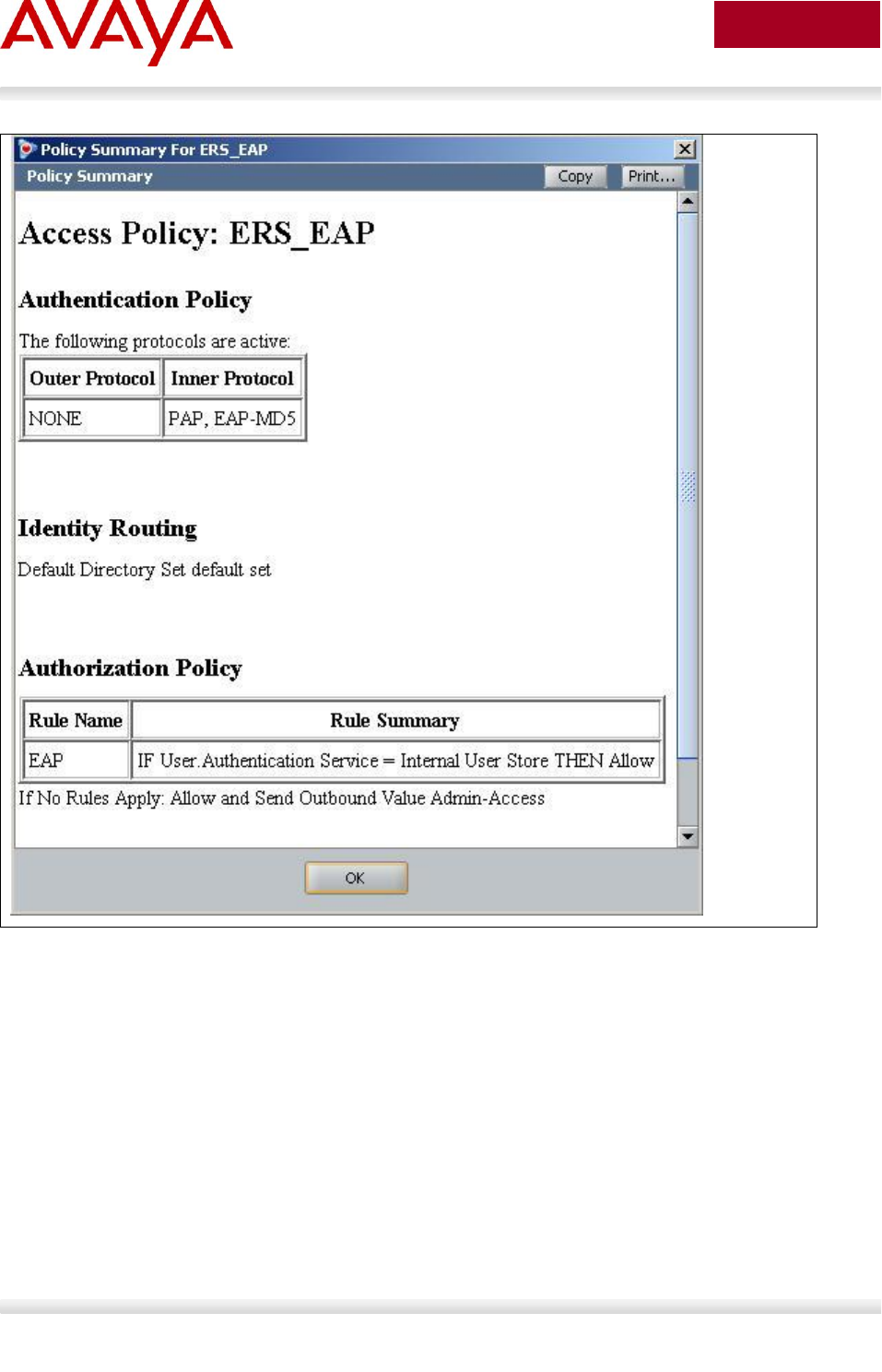
Avaya Inc. – External Distribution
61
avaya.com
Aug 2012

Avaya Inc. – External Distribution
62
avaya.com
Aug 2012
IDE Step 2 – Go to Site Configuration -> Authenticators
For this configuration example, we will create a new container named Avaya Switch
o Under Authenticators, right-click default and add a new container with a
container, add a name of Avaya Switch, and click OK when done
Select Avaya Switch and click on click on New
o Enter the settings as shown below making sure you select the policy we created
above named ERS_EAP via Access Policy. Leave Enable Authenticator and
Enable RADIUS Access checked. Click on OK when done. Please note, the
RADIUS Shared Secret must match the secret entered on the switch

Avaya Inc. – External Distribution
63
avaya.com
Aug 2012
IDE Step 3 – Add Users by going to Site Configuration -> Directories -> Internal Store ->
Internal Users and click on New
Add the EAP users by going to Directories>Internal Store>Internal Users. Next, enter the
User Name and Password as shown below, i.e. User Name = phonea, Password =
Phoneaeselab as per the Avaya IP Phone provisioning files used.
Enter the user name for for the Avaya IP Phone EAP Supplicant via User Name: and
enter the password for this user via Password and Confirm Password. Click on OK when
done. If you wish, you can also change the expiry date via Password Expires if you do
not wish to use the default setting of one year. Repeat again by clicking on New to add
additional internal user names and passwords for each EAP Supplicant.
Assuming we used the user credentials as per the provisioning file for the Avaya 1230 IP
Phone and the MAC address of the Avaya 9640 IP Phone as the default user name, the
internal store user-id’s should like like the following
o Avaya 1230 IP Phone
User Name = phonea, Password = Phoneaeselab
o Avaya 9640 IP Phone
User Name = 001B4F581AD0, Password = 123456

Avaya Inc. – External Distribution
64
avaya.com
Aug 2012
2.8 Auto Configuration with a Stackable Ethernet
Routing Switch using EAP with NEAP and User
Based Policy
The Stackable Ethernet Routing Switch can be configured in one of two methods using NEAP (non-EAP)
to allow an IP phone without an EAP Supplicant access to the network. One method is to enable Non-
EAPOL VoIP phone clients – please see next configuration example.
If you do wish to authenticate the IP Phone via RADIUS using EAP on the switch, but, without enabling
an EAP Supplicant on the phone itself, the Allow Non-EAPOL client’s (NEAP) option can be enabled
where the switch itself will authenticate the IP Phone on its behalf.
The Non-EAPOL VoIP phone clients feature is supported when using the Avaya 1100,
1200, and 2000 series IP Phones. Starting in the 5.1 release for the ERS 3500, present
in release 5.6 (fully supported in release 5.7) for the ERS 4000, and in release 6.3 for
the ERS 5000, the Non-EAPOL VoIP phone clients feature is supported when using the
Avaya 9600 series IP Phones. The Non-EAPOL VoIP phone feature, when enabled on
the switch, will simply authenticate the IP Phone by looking at the DHCP Signature in
the DHCP request packet from the IP Phone. The allows the switch to allow IP Phones
without having to authenticate the IP Phone MAC address against a RADIUS server and
at the same time provide full EAP authentication for the attached PC.
For this example, we will demonstrate how to configure the Stackable Ethernet Routing Switch to allow
for NEAP authentication using RADIUS for the IP Phones. We will also demonstrate using user based
policies to apply QoS for the IP Phones. Hence, instead of configuring filters on the switch to apply QoS
for the voice traffic, we can use a policy triggered by EAP to apply QoS to the voice VLAN.
Any of the stackable Ethernet Routing switches support NEAP (ERS 2500, 4000 or
5000 series), however, only the ERS 5000 series supports user based policies.
The Stackable Ethernet Routing Switch can be configured to accept both EAP and non-EAP (NEAP) on
the same port. In regards to non-EAP, the switch can be configured to accept a password format using
any combination of IP address and MAC address with or without port number. By default, the password
format is set for IP address, MAC address, and port number.
To apply QoS for the IP Phone sets, you can configure the QoS filters on the switch, use ADAC, or use
user based policies (UBP) and trigger the policy via RADIUS authentication. As stated above, we will use
UBP for this configuration example. Once the user based policies has been configured on a switch, the
RADIUS server can reference the policy by using the name given to the UBP policy. User based policies
(UBP) can be used with EAP and/or NEAP.
This configuration example is in reference to diagram 1 and uses the base configuration from example
2.3.
Avaya Inc. – External Distribution
65
avaya.com
Aug 2012
2.8.1 Stackable Switch Configuration
In addition to the base configuration from Section 2.3, we will add the following:
Enable NEAP on ports 3 to 11 on ERS-Stackable using the non-EAP password format of MAC
address only – this will allow the IP Phone to be connected elsewhere in the network on a
different switch without having to worry about port numbers and IP addresses
Configure a user based policy (UBP) for non-EAP IP Phones named voice that will remark both
the DSCP and p-bit values to a CoS value of Premium only for tagged Voice VLAN 220
Configure the RADIUS server NEAP policy using Nortel specific option 562 with vendor-assigned
attribute number 110 and set the string value to UROLvoice.
Please refer to Section 9 for more details regaring EAP configuration on Avaya Switches
Please refer to Section 9 for more details regarding EAP configuration on Avaya Switches
Please note that when setting up the RADIUS server policy for the NEAP group, the
string always starts with UROL. In our example, we configured the ERS5000 with a user
based policy named voice, hence the string value configured on the RADIUS server
must be set to UROLvoice.
2.8.1.1 Configure RADIUS server
ERS-Stackable Step 1 – Add RADIUS server assuming we used a shared key of avaya –
this shared key must also be configured on the RADIUS server for this authenticator
ERS-Stackable(config)#radius server host 172.168.100.50 used-by eapol acct-
enable
ERS-Stackable(config)#radius server host key used-by eapol
Enter key: ******
Confirm key: ******
2.8.1.2 Enable EAP globally
ERS-Stackable Step 1 – Enable non-EAP (NEAP)
ERS-Stackable(config)#eap multihost allow-non-eap-enable
ERS-Stackable Step 2 – Remove the default NEAP password format of
IpAddr.MACAddr.PortNumber
ERS-Stackable(config)#no eapol multihost non-eap-pwd-fmt
ERS-Stackable Step 3 – Enable NEAP password format of MAC address only
ERS-Stackable(config)#eapol multihost non-eap-pwd-fmt mac-addr
ERS-Stackable Step 4 – Enable EAP user-based Policies
ERS-Stackable(config)#eapol user-based-policies enable
Avaya Inc. – External Distribution
66
avaya.com
Aug 2012
ERS-Stackable Step 5 – Enable EAP multihost NEAP policies
ERS-Stackable(config)#eapol multihost non-eap-user-based-policies enable
ERS-Stackable Step 6 – Enable EAP globally
ERS-Stackable(config)#eapol enable
2.8.1.3 Enable EAP at interface level
ERS-Stackable Step 1 – Enable EAP on port 3-11 with NEAP, set the maximum allowable
EAP and NEAP clients to 1, enable EAP multihost and enable RADIUS NEAP phone
ERS-Stackable(config)#interface fastEthernet 3-11
ERS-Stackable(config-if)#eapol status auto
ERS-Stackable(config-if)#eapol multihost allow-non-eap-enable
ERS-Stackable(config-if)#eapol multihost eap-mac-max 1
ERS-Stackable(config-if)#eapol multihost non-eap-mac-max 1
ERS-Stackable(config-if)#eapol multihost radius-non-eap-enable
ERS-Stackable(config-if)#eapol multihost enable
ERS-Stackable(config-if)#exit
2.8.1.4 Configure Policy
ERS-Stackable Step 1 – Configure a policy using the name voice to filter on tagged VLAN
805 and remark DSCP and p-bit to Premium CoS. We will set the eval-order to 5 in case
you wish to add additional filters in the future with a higher preference
ERS-Stackable(config)#qos ubp classifier name voice vlan-min 805 vlan-max 805
vlan-tag tagged ethertype 0x0800 update-dscp 46 update-1p 6 eval-order 4
ERS-Stackable Step 2 – Enable the UBP set
ERS-Stackable(config)#qos ubp set name voice
ERS-Stackable Step 3 – Enable UBP
ERS-Stackable(config)#qos agent ubp high-security-local
The default ubp classifier action non-match action is for forward traffic. In older software
releases for the ERS5500, this was not the case and you had to enter the command qos
ubp set name voice drop-nm-action disable. You can quickly check to see if the
software versions you are using require the drop non-match action by simply typing in
qos ubp set name voice ? and checking if the command drop-nm-action is displayed or
not.

Avaya Inc. – External Distribution
67
avaya.com
Aug 2012
2.8.2 Verify Operations
2.8.2.1 Verify EAP Global and Port Configuration
Step 1 – Verify that EAP has been enabled globally and the correct port members:
ERS-Stackable# show eapol port 3-11
Result:
EAPOL Administrative State: Enabled
Port-mirroring on EAP ports: Disabled
EAPOL User Based Policies: Enabled
EAPOL User Based Policies Filter On MAC Addresses: Disabled
Port: 3
Admin Status: Auto
Auth: No
Admin Dir: Both
Oper Dir: Both
ReAuth Enable: No
ReAuth Period: 3600
Quiet Period: 60
Xmit Period: 30
Supplic Timeout: 30
Server Timeout: 30
Max Req: 2
RDS DSE: No
|
|
Port: 11
Admin Status: Auto
Auth: No
Admin Dir: Both
Oper Dir: Both
ReAuth Enable: No
ReAuth Period: 3600
Quiet Period: 60
Xmit Period: 30
Supplic Timeout: 30
Server Timeout: 30
Avaya Inc. – External Distribution
68
avaya.com
Aug 2012
Max Req: 2
RDS DSE: No
Via the ERS-Stackable switch, verify the following information:
Option
Verify
EAPOL Administrative
State
Verify that the EAPOL is Enabled globally.
EAPOL User Based
Policies
Verify that EAPOL policies are Enabled globally.
Admin Status
Verify that the EAP is enabled on ports 3 to 11 by verifying that the
Admin Status is set to Auto.
Auth
The value will be No even if the IP Phone has successfully
authenticated. Only if there a Supplicant attached to the IP Phone and it
has successfully authenticated will this value change to Yes.
2.8.2.2 Verify EAP Multihost Configuration
Step 1 – Verify that EAP multihost has been globally configured correctly:
ERS-Stackable#show eapol multihost
Result:
Allow Non-EAPOL Clients: Enabled
Use RADIUS To Authenticate Non-EAPOL Clients: Enabled
Allow Non-EAPOL Clients After Single Auth (MHSA): Disabled
Allow Non-EAPOL VoIP Phone Clients: Disabled
EAPOL Request Packet Generation Mode: Multicast
Allow Use of RADIUS Assigned VLANs: Disabled
Allow Use of Non-Eapol RADIUS Assigned VLANs: Disabled
Non-EAPOL RADIUS Password Attribute Format: MACAddr
Non-EAPOL User Based Policies: Enabled
Non-EAPOL User Based Policies Filter On MAC Addresses: Disabled
Use most recent RADIUS VLAN: Disabled
Step 2 – Verify that EAP multihost has been configured correctly at interface level:
ERS-Stackable#show eapol multihost interface 3-11
Result:

Avaya Inc. – External Distribution
69
avaya.com
Aug 2012
Port: 3
MultiHost Status: Enabled
Max Eap Clients: 1
Allow Non-EAP Clients: Enabled
Max Non-EAP Client MACs: 1
Use RADIUS To Auth Non-EAP MACs: Enabled
Allow Auto Non-EAP MHSA: Disabled
Allow Non-EAP Phones: Disabled
RADIUS Req Pkt Send Mode: Multicast
Allow RADIUS VLANs: Disabled
Allow Non-EAP RADIUS VLANs: Disabled
Use most recent RADIUS VLAN: Disabled
|
|
Port: 11
MultiHost Status: Enabled
Max Eap Clients: 1
Allow Non-EAP Clients: Enabled
Max Non-EAP Client MACs: 1
Use RADIUS To Auth Non-EAP MACs: Enabled
Allow Auto Non-EAP MHSA: Disabled
Allow Non-EAP Phones: Disabled
RADIUS Req Pkt Send Mode: Multicast
Allow RADIUS VLANs: Disabled
Allow Non-EAP RADIUS VLANs: Disabled
Use most recent RADIUS VLAN: Disabled
Avaya Inc. – External Distribution
70
avaya.com
Aug 2012
Via the ERS-Stackable switch, verify the following information:
Option
Verify
Allow Non-EAPOL
Clients:
Verify that the non-EAPOL (NEAP) is Enabled globally.
Use RADIUS To
Authenticate Non-
EAPOL Clients:
Verify the use RADUIS to authenticate non-EAPOL option is Enabled
globally.
Non-EAPOL RADIUS
Password Attribute
Format:
Verify that the non-EAP password format is set for MACAddr. Please
note, some of the older software releases required a leading period “.”
before and after the MAC address.
Non-EAPOL User
Based Policies:
Verity that the non-EAPOL user based policies is Enabled
2.8.2.3 Verify EAP Multihost Status
Step 1 – Assuming the IP Phone via port 3 has successfully authenticated via EAP, use the
following command to view the EAP status:
ERS-Stackable# show eapol multihost non-eap-mac status
Result:
Port Client MAC Address State
---- ------------------ ------------------------------
3 00:24:00:0D:8D:29 Authenticated By RADIUS
4 00:24:00:0D:8D:AA Authenticated By RADIUS
On the ERS-Stackable switch, verify the following information:
Option
Verify
Port
Display the ports where the IP Phone has successfully been
authenticated.
Client MAC Address
If the IP phone has successfully authenticated via NEAP, its MAC
address should be shown.
State
Verity that Authenticated By RADIUS is displayed

Avaya Inc. – External Distribution
71
avaya.com
Aug 2012
2.8.2.4 Verify EAP Policy
Step 1 – Use the following command to view the UBP Policy:
ERS-Stackable# show qos ubp classifier
Result:
Id: 1
Name: voice
Block:
Eval Order: 5
Address Type: IPv4
Destination Addr/Mask: Ignore
Source Addr/Mask: Ignore
DSCP: Ignore
IPv4 Protocol / IPv6 Next Header: Ignore
Destination L4 Port Min: Ignore
Destination L4 Port Max: Ignore
Source L4 Port Min: Ignore
Source L4 Port Max: Ignore
IPv6 Flow Id: Ignore
IP Flags: Ignore
TCP Control Flags: Ignore
IPv4 Options: Ignore
Destination MAC Addr: Ignore
Destination MAC Mask: Ignore
Source MAC Addr: Ignore
Source MAC Mask: Ignore
VLAN: 805
VLAN Tag: Tagged
EtherType: 0x0800
802.1p Priority: All
Packet Type: Ignore
Inner VLAN: Ignore
Action Drop: No
Action Update DSCP: 0x2E
Action Update 802.1p Priority: Priority 6
Action Set Drop Precedence: Low Drop
Avaya Inc. – External Distribution
72
avaya.com
Aug 2012
Storage Type: NonVolatile
Via the ERS-Stackable switch, verify the following information:
Option
Verify
Name:
Verify the port number is correct, should be voice for this example.
Eval Order:
Verify the port number is correct, should be 5 for this example.
Address Type:
Verify the Address Type is correct, should be IPv4 for this example.
VLAN:
Verify VLAN is correct, should be 805 for this example.
EtherType:
Verify the EtherType is correct, should be 0x0800 representing the IP
for this example.
Action Update DSCP:
Verify the DSCP value is correct, should be 0x2e (decimal 46) for this
example.
Action Update 802.1p
Priority:
Verify the p-bit value is correct, should be 6 for this example.
2.8.2.5 Verify EAP Policy upon the NEAP client successfully
authenticating
Step 1 – Assuming an IP Phone via port 3 and 4 has successfully authenticated via EAP,
use the following command to view the UBP Policy:
ERS-Stackable# show qos ubp interface
Result:
Id Unit Port Filter Set Name
_____ ____ ____ _______________
55001 1 3 voice
55002 1 4 voice
Via the ERS-Stackable switch, verify the following information:
Option
Verify
Port
Verify the port number is correct according the NEAP authenticated IP
Phones
Filter Set Name
If the IP phone has successfully authenticated via NEAP, and if the
RADIUS server has been configured correctly, the policy named voice
will be displayed.

Avaya Inc. – External Distribution
73
avaya.com
Aug 2012
2.8.2.6 View EAP Policy Statistics
Step 1 – You can view the statistics by using the UBP reference and port number using the
following command. Please note that the reference number for each port will be different.
ERS-Stackable# show qos statistics 55001 port 3
Result:
Id: 55001
Policy Name: UntrustedClfrs1
Classifier Unit/Port In-Profile
Name Packets
________________ _________ ____________________
1/3 203
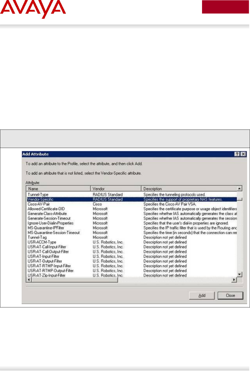
Avaya Inc. – External Distribution
74
avaya.com
Aug 2012
2.8.3 RADIUS Server – Policy Setup
2.8.3.1 Microsoft IAS
Assuming the RADIUS server is a Windows 2003 server, via the IAS Remote Access Policies, go to your
NEAP policy Advanced settings. The Vendor-Specific attribute should be setup as follows.
Vendor Code : Nortel ; Nortel Specific Option 562
Vendor-assigned attribute
o Attribute number : 110
o Attribute format : String
o Attribute value : UROLvoice
Step 1 – Via IAS, assuming you have already started a NEAP policy, go the Advanced tab and click
on Add and scroll down to Vendor-Specific and click on Add
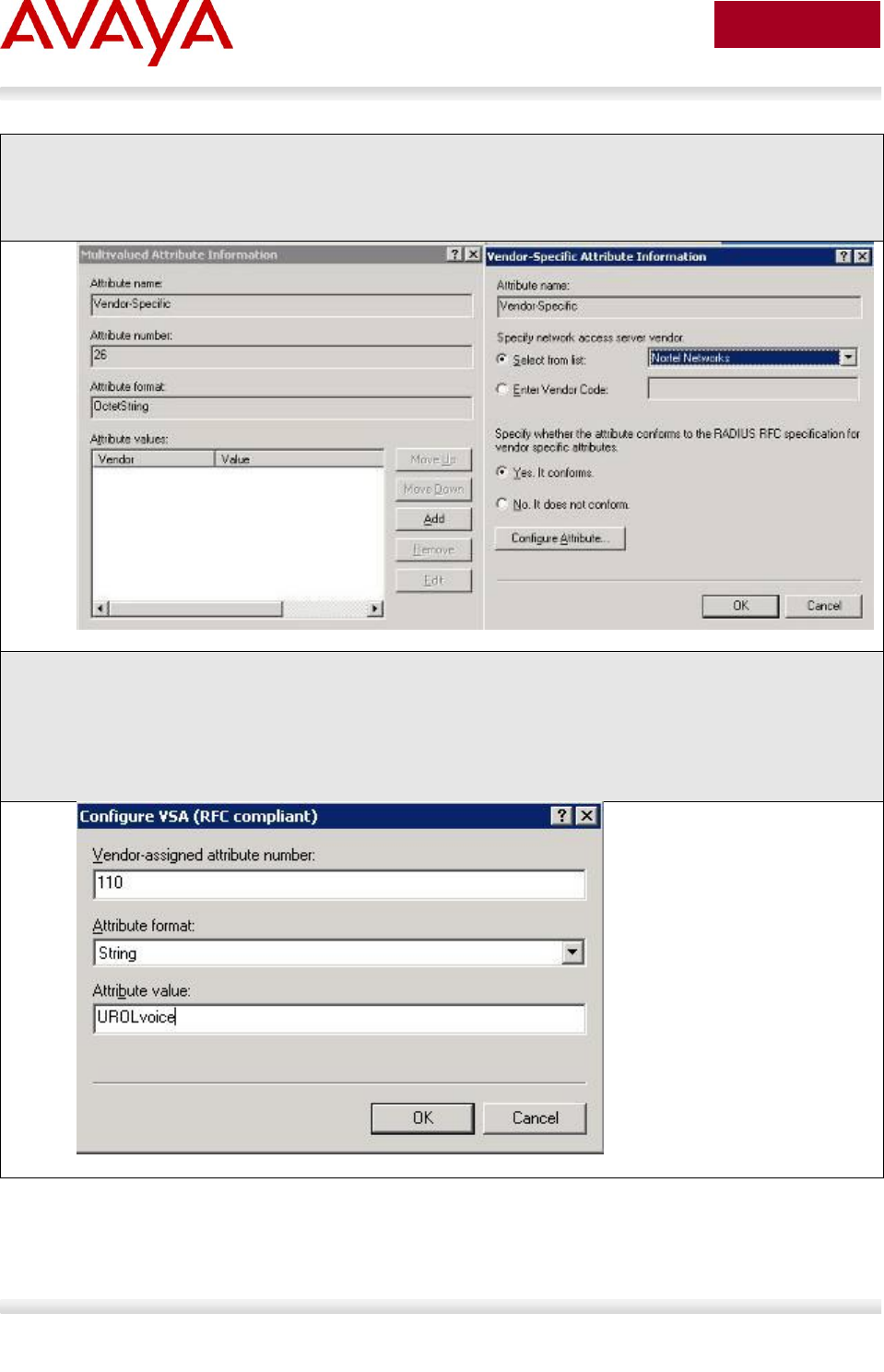
Avaya Inc. – External Distribution
75
avaya.com
Aug 2012
Step 2 - Via the Multivalued Attribute Information window, click on Add. In the next window titled
Vendor-Specific Attribute Information, click no the Select from list radio button and select Nortel
Networks and click on the Yes, it conforms radio button. When finished, click on Configure
Attributes.
Step 3: Via the Configure VSA (RFC compliant) window, enter the following:
o Vendor-assigned attribute number: 110
o Attribute formate: String
o Attribute value: UROLvoice
Click on OK when done.
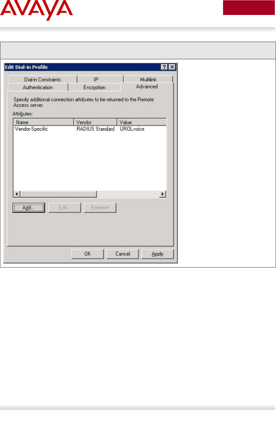
Avaya Inc. – External Distribution
76
avaya.com
Aug 2012
Step 4 – When completed, the profile should be as that displayed below.
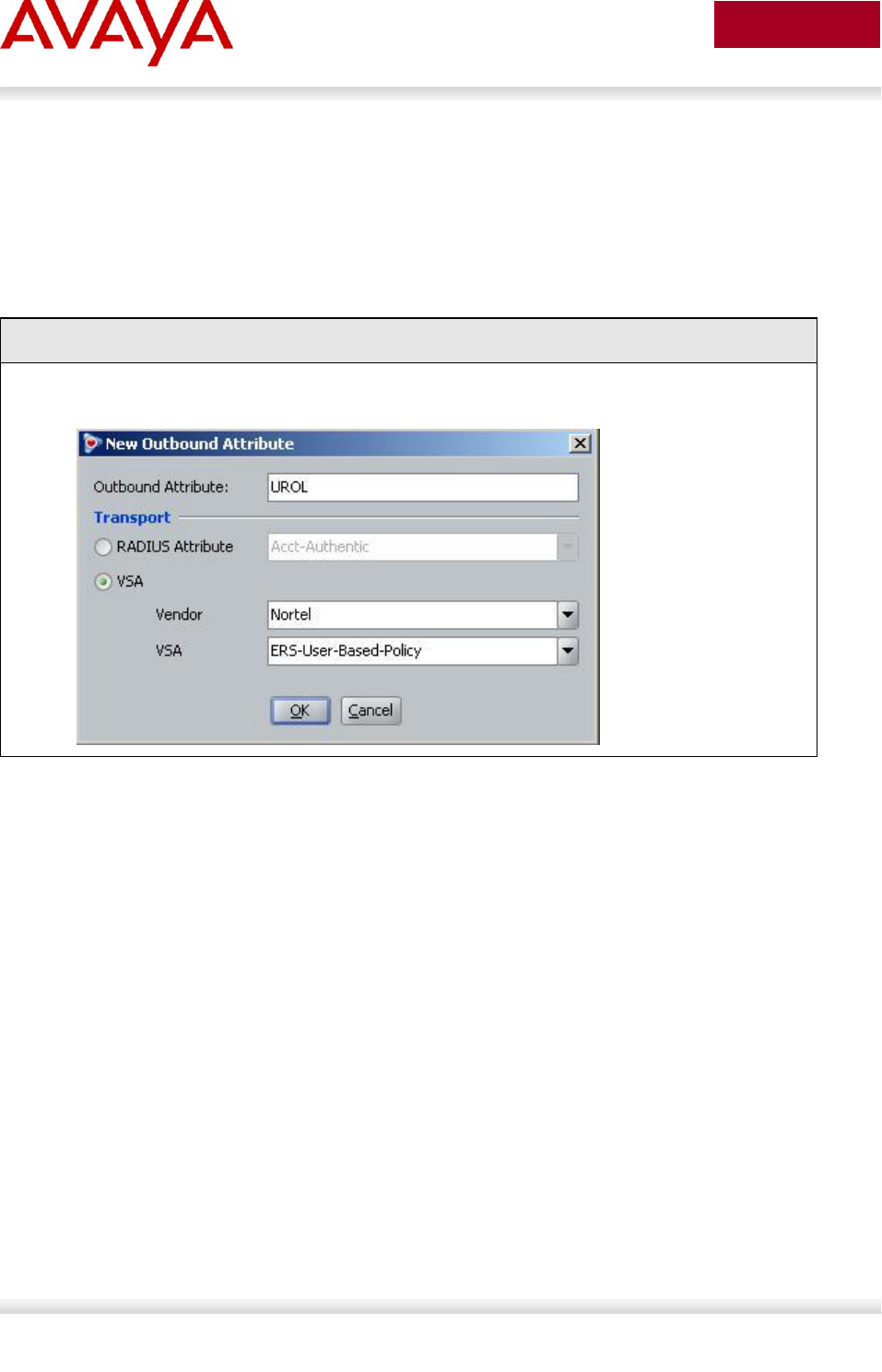
Avaya Inc. – External Distribution
77
avaya.com
Aug 2012
2.8.3.2 Avaya Identity Engines Ignition Server
Using the base IDE configuration in Section 2.7.3, we will simply add the appropriate outbound attribute
to the Access Policy.
Please note, the Nortel vendor specific attributes are already added and can be viewed by going to Site
Configuration -> Provisioning -> Vendors/VSAs and scrolling down and selecting Nortel -> VSA
Definitions. For this example, we will use the VSA Definition ERS-User-Based-Policy.
IDE Step 1 – Go to Site Configuration -> Provisioning -> Outbound Attributes -> New
When the New Outbound Attribute window pops up, enter the following as shown below.
As shown below, in this example, we simply named the outbound attribute UROL
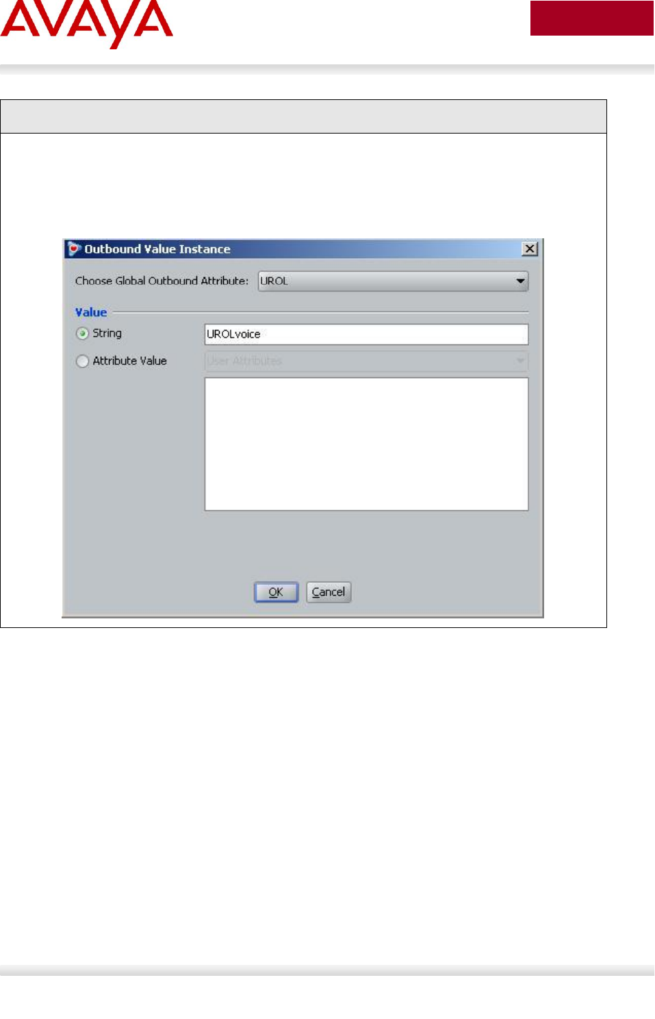
Avaya Inc. – External Distribution
78
avaya.com
Aug 2012
IDE Step 2 – Go to Site Configuration -> Provisioning -> Outbound Values -> New
When the Outbound Value Details window pops up, enter a name, i.e. UROLvoice as
used in this example, and click on New
When the Outbound Value Instance window pops up, enter the following as shown
below. Please note, the String value must be UROLvoice as “voice” is the name of the
policy defined on the switch in this configuration example. Click OK twice when done
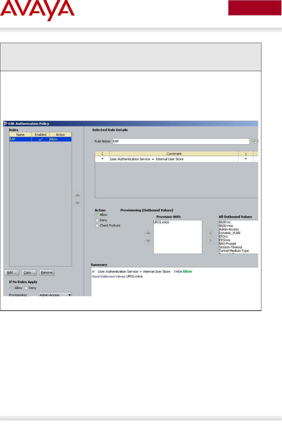
Avaya Inc. – External Distribution
79
avaya.com
Aug 2012
IDE Step 3 – Go to Site Configuration -> Access Policies-> RADIUS -> ERS_EAP ->
Authorization Policy -> Edit (assuming we are using the policy we configured in Section
2.7.3 named “ERS_EAP”)
From the All Outbound Values windows, select UROLvoice and then click on the “less-
than” arrow key
Click OK when done
This should move the outbound attribute named UROLvoice to the Provision With
window as shown below
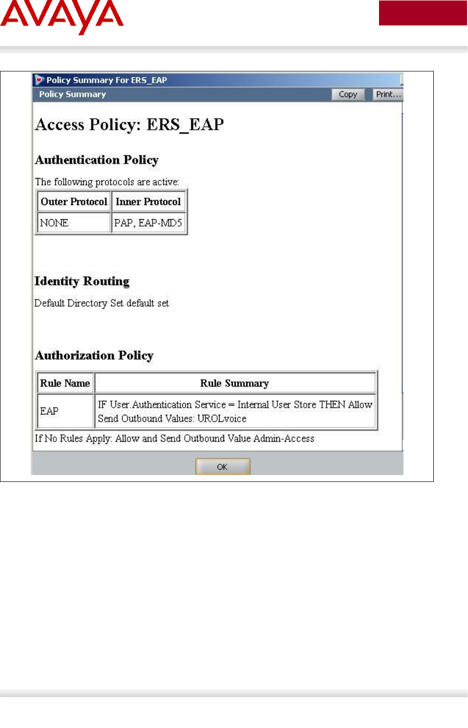
Avaya Inc. – External Distribution
80
avaya.com
Aug 2012

Avaya Inc. – External Distribution
81
avaya.com
Aug 2012
2.9 Auto Configuration with a Stackable Ethernet
Routing Switch using EAP with Fail Open VLAN,
Guest VLAN, and RADIUS Assigned VLAN for PC
Supplicant
Providing we enable the voice VLAN feature on the ERS 3500, 4000 and ERS 5000, we can now
provision EAP with open fail VLAN, guest VLAN, and RADIUS assigned VLAN with EAP or non-eap-
phone for the IP phone set. Please see section 5.1 for more details regarding voice VLAN.
Assuming we wish to accomplish the following:
Allow non-eap-phone for the Avaya 1230 IP Phones
Provide RADIUS Assigned VLAN provisioning for the PC supplicant connected to any of the IP
Phones in addition to allowing EAP Guest VLAN, and fail-open VLAN
The Non-EAPOL VoIP phone clients feature is supported when using the Avaya 1100,
1200, and 2000 series IP Phones. Starting in the 5.1 release for the ERS 3500, present
in release 5.6 (fully supported in release 5.7) for the ERS 4000, and in release 6.3 for
the ERS 5000, the Non-EAPOL VoIP phone clients feature is supported when using the
Avaya 9600 series IP Phones. The Non-EAPOL VoIP phone feature, when enabled on
the switch, will simply authenticate the IP Phone by looking at the DHCP Signature in
the DHCP request packet from the IP Phone. The allows the switch to allow IP Phones
without having to authenticate the IP Phone MAC address against a RADIUS server and
at the same time provide full EAP authentication for the attached PC.
2.9.1 Stackable Switch Configuration
For example, we will use the base configuration from example 2.3 and add guest VLAN 1011 and fail
open VLAN 1012
2.9.1.1 Configure RADIUS server
ERS-Stackable Step 1 – Add RADIUS server
ERS-Stackable(config)#radius server host 172.168.100.50 used-by eapol acct-
enable
ERS-Stackable(config)#radius server host key used-by eapol
Enter key: ******
Confirm key: ******
Avaya Inc. – External Distribution
82
avaya.com
Aug 2012
2.9.1.2 VLAN provisioning
Make sure VLAN 805 is provisioned as a voice VLAN – ERS 4000 and ERS 5000 only.
ERS-Stackable Step 1 – Provision VLAN 805 as the voice VLAN
ERS-Stackable(config)# vlan voice-vlan 805
ERS-Stackable Step 2 – Add guest VLAN 1011 and open fail VLAN 1012
ERS-Stackable(config)#vlan create 1011 type port
ERS-Stackable(config)#vlan create 1012 type port
2.9.1.3 Enable EAP globally
ERS-Stackable Step 1 – Enable EAP MHMA with non-eap-phone, guest VLAN, and fail open
VLAN
ERS-Stackable(config)#eapol multihost non-eap-phone-enable
ERS-Stackable(config)#eapol multihost use-radius-assigned-vlan
ERS-Stackable(config)#eapol guest-vlan enable vid 1011
ERS-Stackable(config)#eapol multihost fail-open-vlan enable
ERS-Stackable(config)#eapol multihost fail-open-vlan vid 1012
ERS-Stackable(config)#eapol multihost voip-vlan 1 enable vid 805
ERS-Stackable Step 2 – Enable EAP
ERS-Stackable(config)#eapol enable
ERS-Stackable Step 3 – If ADAC and non-eap-phone is enabled, enter the following
command
ERS-Stackable(config)#eapol multihost dummy-adac-radius-requests enable
When you have NEAP enabled on a port, as soon as the MAC address of a new device is
learnt, the switch will send out a RADIUS request with the device MAC Address. After which the
switch may then send another request if the client has a supplicant. The reason this occurs is
because Address learning happens first and in hardware.
Similar actions happen when you have an IP Phone. If you have NEAP enabled and plug in an
IP Phone, once the MAC is learnt on the port the switch will send a RADIUS request. Now if
NEAP IP Phone is enabled, the switch does not initially know that it is an IP Phone, so when the
MAC is learnt then it should likewise send a RADIUS request for the MAC. After this if NEAP IP
Phone is enabled, it is only after the phone sends out a DHCP request, that we see the
appropriate signature and then authenticate the device based on the DHCP Signature.
So in both cases this should stop extra requests to the RADIUS server.

Avaya Inc. – External Distribution
83
avaya.com
Aug 2012
2.9.1.4 Enable EAP at interface level
ERS-Stackable Step 1 – Enable EAP on ports 3 to 11 with non-eap-phone and use-radius-
assigned-vlan enabled
ERS-Stackable(config)#interface fastEthernet 3-11
ERS-Stackable(config)#eapol status auto
ERS-Stackable(config-if)#eapol multihost enable non-eap-phone-enable use-
radius-assigned-vlan
ERS-Stackable(config-if)#eapol guest-vlan enable vid 1011
ERS-Stackable(config-if)#exit

Avaya Inc. – External Distribution
84
avaya.com
Aug 2012
2.9.2 Verify Operations
Assuming we have an Avaya IP phone with a Supplicant connected to port 7 and an Avaya IP Phone
connected to port 8 with the following characteristics:
Port 7:
o Avaya IP Phone 1230 with MAC address 00-24-00-0d-8d-29
o Supplicant with MAC address 00:02:A5:E9:00:28
Port 8:
o Avaya IP Phone 1230 with MAC address 00-24-00-0d-8d-aa
2.9.2.1 Verify EAP Global and Port Configuration
Step 1 – Verify that EAP has been enabled globally and the correct port members:
ERS-Stackable#show eapol port 3-11
Result:
EAPOL Administrative State: Enabled
Port: 3
Admin Status: Auto
Auth: No
Admin Dir: Both
Oper Dir: Both
ReAuth Enable: No
ReAuth Period: 3600
Quiet Period: 60
Xmit Period: 30
Supplic Timeout: 30
Server Timeout: 30
Max Req: 2
RDS DSE: No
|
Port: 7
Admin Status: Auto
Auth: Yes
Admin Dir: Both
Oper Dir: Both
ReAuth Enable: No
ReAuth Period: 3600

Avaya Inc. – External Distribution
85
avaya.com
Aug 2012
Quiet Period: 60
Xmit Period: 30
Supplic Timeout: 30
Server Timeout: 30
Max Req: 2
RDS DSE: No
Port: 8
Admin Status: Auto
Auth: Yes
Via the ERS-Stackable switch, verify the following information:
Option
Verify
EAPOL Administrative
State
Verify that the EAPOL is Enabled globally.
Auth
For any port that has a Supplicant which has successfully been
authenticated, the Auth state should be Yes
2.9.2.2 Verify EAP Multihost Configuration
Step 1 – Verify that EAP multihost has been globally configured correctly:
ERS-Stackable#show eapol multihost
Result:
Allow Non-EAPOL Clients: Disabled
Use RADIUS To Authenticate Non-EAPOL Clients: Disabled
Allow Non-EAPOL Clients After Single Auth (MHSA): Disabled
Allow Non-EAPOL VoIP Phone Clients: Enabled
EAPOL Request Packet Generation Mode: Multicast
Allow Use of RADIUS Assigned VLANs: Enabled
Allow Use of Non-Eapol RADIUS Assigned VLANs: Disabled
Non-EAPOL RADIUS Password Attribute Format: IpAddr.MACAddr.PortNumber
EAPOL Protocol: Enabled
Use most recent RADIUS VLAN: Disabled
Non-EAP re-authentication: Disabled
Dummy ADAC Radius Requests: Enabled
Avaya Inc. – External Distribution
86
avaya.com
Aug 2012
Via the ERS-Stackable switch, verify the following information:
Option
Verify
Allow Non-EAPOL
VoIP Phone Clients
Verify the allow non-EAPOL VoIP Phone Clients option is Enabled
globally.
2.9.2.3 Verify EAP Multihost Port configuration
Step 1 – Verify that EAP mulltihost configuration:
ERS-Stackable#show eapol multihost interface 3-11
Result, i.e. for port 3:
Port: 3
MultiHost Status: Enabled
Max Eap Clients: 1
Allow Non-EAP Clients: Disabled
Max Non-EAP Client MACs: 1
Use RADIUS To Auth Non-EAP MACs: Disabled
Allow Auto Non-EAP MHSA: Disabled
Allow Non-EAP Phones: Enabled
RADIUS Req Pkt Send Mode: Multicast
Allow RADIUS VLANs: Enabled
Allow Non-EAP RADIUS VLANs: Disabled
EAPOL Protocol: Enabled
Use most recent RADIUS VLAN: Disabled
|
|
Port: 11
MultiHost Status: Enabled
Max Eap Clients: 1
Allow Non-EAP Clients: Disabled
Max Non-EAP Client MACs: 1
Use RADIUS To Auth Non-EAP MACs: Disabled
Allow Auto Non-EAP MHSA: Disabled
Allow Non-EAP Phones: Enabled
RADIUS Req Pkt Send Mode: Multicast
Allow RADIUS VLANs: Disabled
Allow Non-EAP RADIUS VLANs: Enabled
EAPOL Protocol: Enabled

Avaya Inc. – External Distribution
87
avaya.com
Aug 2012
Use most recent RADIUS VLAN: Disabled
Via the ERS-Stackable switch, verify the following information:
Option
Verify
MultiHost Status
Verify that the MultiHost status is Enabled on port 3 to 11.
Max Eap Client
Verify that the maximum EAP client is set to 1. If not, check your
configuration
Max Non-EAP Client
MACs
Verify that the maximum non-EAP client is set to 1. If not, check your
configuration
Allow Non-EAP
Phones
Verify that Allow Non-EAP Phone is set to Enabled. If not, check your
configuration
Avaya Inc. – External Distribution
88
avaya.com
Aug 2012
2.9.2.4 Verify EAP Multihost Status
Step 1 – Assuming the Supplicant via port 8 has successfully authenticated via EAP, use
the following command to view the EAP status:
ERS-Stackable#show eapol multihost status
Result:
Port Client MAC Address Pae State Backend Auth State
---- ------------------ -------------- ------------------
7 00:02:A5:E9:00:28 Authenticated Idle
=========Neap Phones============
7 00-24-00-0d-8d-29
8 00-24-00-0d-8d-aa
Via the ERS-Stackable switch, verify the following information:
Option
Verify
Client MAC Address
Verify the actual Supplicant MAC. For this example, this should be
00:02:A5:E9:00:28 on port 7.
Pae State
Verify the actual Supplicant Pae State. If the Supplicant has
successfully authenticated, the Pae State should be displayed as
Authenticated
Neap Phones
Verify the actual MAC for the Avaya IP Phone sets. For this example,
this should be 00-24-00-0d-8d-29 on port 7 and 00-24-00-0d-8d-aa on
port 8

Avaya Inc. – External Distribution
89
avaya.com
Aug 2012
2.10 Avaya IP Phone – DHCP and Provisioning Files
Details regarding various Avaya IP Phone DHCP and configuration file paramteters are listed in Appendix
A. List below are the mimimum settings required for this configuration example.
2.10.1 DHCP Settings
The following assumptions apply:
The voice VLAN id is 805
We will use the HTTP provisioning server as illustrated in diagram 1 using an IP address of
192.168.50.100
o The file path for the Avaya 9640 IP Phone is 9600/96xxH323_032910
o The file path for the Avaya 1230 IP Phone is phone_prov_files
DHCP Server Step 1 – Data VLAN DHCP Scope settings for the Avaya 1230 IP Phone
Option 191 String Value
VLAN-A:805.
DHCP Server Step 1 – Data VLAN DHCP Scope settings for the Avaya 9640 IP Phone
Option 242 String Value
L2Q=1
L2QVLAN=805
VLANTEST=60
DHCP Server Step 2 – Voice VLAN DHCP Scope settings for the Avaya 1230 IP Phone
Option 224 String Value
Nortel-i2004-B,prov=http://192.168.50.100/phone_prov_files;
DHCP Server Step 2 – Voice VLAN DHCP Scope settings for the Avaya 9640 IP Phone
Option 242 String Value
HTTPSRVR=192.168.50.100
HTTPDIR= 9600/96xxH323_032910

Avaya Inc. – External Distribution
90
avaya.com
Aug 2012
2.10.2 Provisioning Files
The following shows the configuration files used for this example.
Avaya 1230 IP Phone provisioning Files – Files include system.prv, 1230.prv, and
0024000D8DAA.prv (includes EAP MD5 configuration)
system.prv
file=td;
s1ip=10.88.2.20;
p1=4100;
a1=1;
rl=2;
s2ip=10.88.2.20;
p2=4100;
a2=1;
r2=2;
1230.prv
lldp=y;
igarp=y;
vq=y;
vlanf=y;
pc=y;
dq=n;
pcuntag=y;
reg=00:24:00:0D:8D:AA,CS1K,S1S2,600,096-00-00-20;
0024000D8DAA.prv
eap=md5;
eapid1=phoneb;
eappwd=Phonebeselab;
Avaya 9640 IP phone provisioning File – File used is 46xxxsettings.txt (includes EAP MD5
configuration)
46xxsettings.txt
SET HTTPSRVR 192.168.50.100
SET HTTPDIR 9600\96xxH323_032910
SET VLANTEST 60
SET PROCSTAT 0
SET PROCPSWD 27238
SET PHY1STAT 1

Avaya Inc. – External Distribution
91
avaya.com
Aug 2012
SET PHY2STAT 1
SET MCIPADD 10.30.30.20
SET DOT1XSTAT 2
SET DOT1X 0
SET DOT1XEAPS "MD5"
Avaya Inc. – External Distribution
92
avaya.com
Aug 2012
2.11 Avaya Energy Saver (AES)
In reference to Diagram 1, assume we wish to enable AES to ERS-Stackable with the following schedule:
Activate AES during the week from Monday to Friday nighttime from 7:00 pm to 6:30 am
Deactivate AES on Saturday from 7:00 am to 5:00 pm
2.11.1 Go to configuration mode.
ERS-Stackable: Step 1 - Enter configuration mode
ERS-Stackable>enable
ERS-Stackable#config terminal
2.11.2 Add SNTP Server
ERS-Stackable: Step 1 – Add an SNTP server
ERS-Stackable(config)#sntp server primary address 192.168.50.100
ERS-Stackable(config)#sntp enable
2.11.3 Add Avaya Energy Saver configuration
ERS-Stackable: Step 1 – Enable AES at interface level
ERS-Stackable(config)#interface fastEthernet all
ERS-Stackable(config-if)#energy-saver enable
ERS-Stackable(config-if)#exit
ERS-Stackable: Step 2 – Enable AES schedule
ERS-Stackable(config)#energy-saver schedule weekday 06:30 deactivate
ERS-Stackable(config)#energy-saver schedule weekday 19:00 activate
ERS-Stackable(config)#energy-saver schedule saturday 07:00 deactivate
ERS-Stackable(config)#energy-saver schedule saturday 17:00 activate
ERS-Stackable(config)#energy-saver enable
For test purposes, you can activate/deactivate AES by issuing the following commands
from the ACLI Privileged level:
ERS-Stackable#energy-saver activate
ERS-Stackable#energy-saver deactivate
Avaya Inc. – External Distribution
93
avaya.com
Aug 2012
2.11.4 Verify operations
2.11.4.1 Verify SNTP
SNTP must be configured and running for AES to operate. The switch must have SNTP enabled to
correctly obtain the time for operation of AES if the scheduler is configured.
Step 1 – Verify SNTP is configured
ERS-Stackable#show sntp
Result:
SNTP Status: Enabled
Primary server address: 192.168.50.100
Secondary server address: 0.0.0.0
Sync interval: 24 hours
Last sync source: 192.168.50.100
Primary server sync failures: 0
Secondary server sync failures: 0
Last sync time: 2010-06-22 09:43:31 GMT-01:00
Next sync time: 2010-06-23 09:43:31 GMT-01:00
Current time: 2010-06-22 14:52:16 GMT-01:00
Step 2 – Verify clock
ERS-Stackable#show clock
Result:
Current SNTP time : 2010-06-22 14:51:11 GMT-01:00
Summer time recurring is set to:
start: on Sunday in the 4th week of March at 02:00
end: on Sunday in the 4th week of October at 02:00
Offset: 60 minutes.
Summer time is set to:
start: 29 March 2010 at 02:00
end: 30 October 2010 at 03:00
Offset: -60 minutes. Time zone will be 'EDT'
Time zone is set to 'EST', offset from UTC is -02:00

Avaya Inc. – External Distribution
94
avaya.com
Aug 2012
2.11.4.2 Verify AES
Use the following commands to verify AES is operational. In this example, we will show the effect of AES
with a model 1120E IP phone connected to port 1/9. Prior to AES activation, the 1120E should be
operating at 1000Mbps full duplex. After AES activation, the 1120E should be operating at 10Mbps full
duplex.
Step 1 – Verify AES is configured at interface level
ERS-Stackable#show energy-saver interface
Result:
Unit/Port AES State PoE Savings PoE Priority
--------- --------- ----------- ------------
1/1 Enabled Disabled Low
1/2 Enabled Disabled Low
|
|
Step 2 – Verify Port is delivering PoE power; the following shows the power measured
prior to and after AES activation
ERS-Stackable#show poe-power-measurement 1/9
Result:
The following shows the PoE power delivered prior to AES activation:
Unit/Port Volt(V) Current(mA) Power(Watt)
--------- ------- ----------- ---------------
1/9 47.5 125 6.000
The following show the PoE power delivered after AES activation:
Unit/Port Volt(V) Current(mA) Power(Watt)
--------- ------- ----------- ---------------
1/9 47.5 95 4.500

Avaya Inc. – External Distribution
95
avaya.com
Aug 2012
Step 3 – Verify Ethernet interface speed; the following shows the port speed prior to and
after AES activation
ERS-Stackable#show poe-port-status 1/9
Result:
The following displays the interface speed prior to AES activation:
Status Auto Flow
Unit/Port Trunk Admin Oper Link LinkTrap Negotiation Speed Duplex Control
--------- ----- ------- ---- ---- -------- ----------- -------- ------ -------
1/9 Enable Up Up Enabled Enabled 1000Mbps Full Symm
The following displays the interface speed after AES is activated:
Status Auto Flow
Unit/Port Trunk Admin Oper Link LinkTrap Negotiation Speed Duplex Control
--------- ----- ------- ---- ---- -------- ----------- -------- ------ -------
1/9 Enable Up Up Enabled Enabled 10Mbps Full Disable
Step 4 – Verify AES globally settings
ERS-Stackable#show energy-saver
Result:
Avaya Energy Saver (AES): Enabled
AES PoE Power Saving Mode: Disabled
AES Efficiency-Mode Mode: Disabled
Day/Time: Tuesday 20:58:58
Current AES state: AES is Active
Step 5 – Verify AES schedule
ERS-Stackable#show energy-saver schedule
Result:
Day Time Action
--------- ----- -----------
Monday 06:30 Deactivate
Monday 19:00 Activate
Tuesday 06:30 Deactivate
Tuesday 19:00 Activate

Avaya Inc. – External Distribution
96
avaya.com
Aug 2012
Wednesday 06:30 Deactivate
Wednesday 19:00 Activate
Thursday 06:30 Deactivate
Thursday 19:00 Activate
Friday 06:30 Deactivate
Friday 19:00 Activate
Saturday 07:00 Deactivate
Saturday 17:00 Activate
Step 6 – Verify AES power savings; the following shows the power savings after AES
activation
ERS-Stackable# show energy-saver savings
Result:
Prior to AES activation:
Unit# Model Switch Capacity Saving PoE Saving
----- ------------ ---------------------- -------------------
1 5698TFD-PWR 0.0 watts 0.0 watts
-------------------------------------------------------------
TOTAL 0.0 watts 0.0 watts
=============================================================
After AES activation:
Unit# Model Switch Capacity Saving PoE Saving
----- ------------ ---------------------- -------------------
1 5698TFD-PWR 2.7 watts 0.0 watts
-------------------------------------------------------------
TOTAL 3.6 watts 0.0 watts
=============================================================

Avaya Inc. – External Distribution
97
avaya.com
Aug 2012
2.12 DHCP Server Setup
The following setup applies to configuring a DHCP server for auto configuration. Depending on the Avaya
IP phone series used, the DHCP options can vary.
VLAN Setting using DHCP
Double DHCP is a term used where the IP Phone learns the voice VLAN Id using DHCP. From a default
setting, all IP Phones send out traffic untagged and use DHCP to get an IP address. Providing you
configure the data VLAN scope with the correct DHCP options, the IP Phone will learn the voice VLAN ID
from the data VLAN and then proceed to request for a new IP address now via the tagged voice VLAN.
This method provides separation for voice and data traffic allowing for a PC or any other data device to
be directly connected to the IP Phone set. The IP Phone can be also be setup to either leave the data
traffic untagged or tag the data VLAN using a different VLAN Id other than that of the voice VLAN.
Depending on the Avaya IP Phone model, the VLAN and IP address may be cached so this double
DHCP process actually only occurs once. The Avaya 1600, 4600, and 9600 series cache both the IP
address and VLAN Id. Hence, upon a power cycle, the Avaya IP Phone will request an IP address directly
via the tagged voice VLAN without having to perform double DHCP. The Avaya 1100, 1200, and 2000
series have an option to cache the IP address, but, this only comes into effect if a DHCP server is
unreachable – in other words, the IP phone will continue to perform double DHCP unless the DHCP
server is unreachable.
Depending on the Avaya IP phone model, the following DHCP option should be configured. Details on
each on these items are described in detail latter in this document and in the appendixes.
Avaya 1100, 1200, and 2000 Series
o Option 191
Avaya 4600 Series
o Option 176
Avaya 1600 and 9600 Series
o Option 242
IP Phone Settings using DHCP
A limited set of IP phone settings can be set by DHCP. Details are covered in detail later in this document
and in the appendixes. More detailed IP phone configuration should be done using a provisioning server
which can be set via the voice VLAN. Depending on the Avaya IP phone model, the following DHCP
option should be configured.
Avaya 1100, 1200, and 2000 Series
o Option 128- prior to UNIStim firmware release 2.2
Call Server settings only
o Option 128, 131, 144, 157, 188, 191, 205, 219, 223, 224, 227, 230, 232, 235, 238, 241,
244, 247, 251 or 254 - UNIStim firmware release 2.2 and greater
Extended IP phone settings
Avaya 4600 Series
o Option 176
Avaya 1600 and 9600 Series
o Option 242
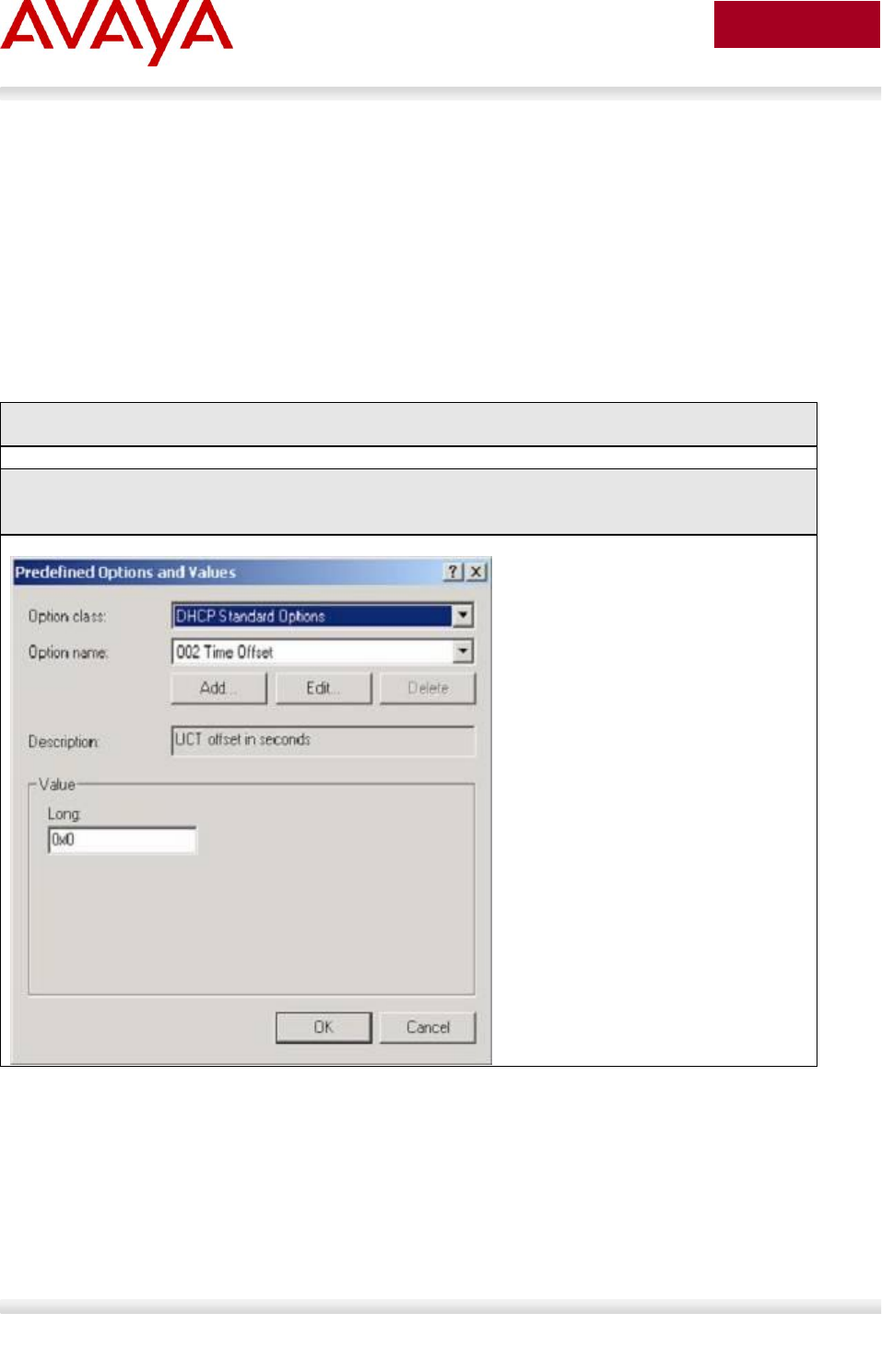
Avaya Inc. – External Distribution
98
avaya.com
Aug 2012
The following configuration example shows how to setup a DHCP server for Avaya IP phone. In our
example, a Windows 2003 server will be used.
2.12.1 Windows 2003 DHCP Configuration
For this configuration example, we will create the following
Option 224 and 191 to be used for the Avaya 1100, 1200, and 2000 Series Series IP phones
Option 242 to be used for the Avaya 1600 and 9600 Series IP Phones
2.12.1.1 Default DHCP Options
Windows 2003 Server Step 1 – Go to the following
Start->Administrative Tools->DHCP
Windows 2003 Server Step 2 – Create DHCP Options by high-lighting the name on of your
DHCP server from the top menu and select the following
Action -> Set Predefined Options -> Add
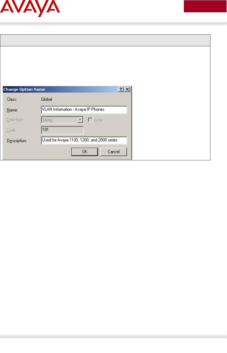
Avaya Inc. – External Distribution
99
avaya.com
Aug 2012
Windows 2003 Server Step 3 – Add a new DHCP option, create DHCP option 191
After clicking on Add, fill in the information as shown below for the DHCP option with the identifier
set to 191.
Name: Any name you like
Set Date type: String
Code: 191
Description: Add any comments if you like
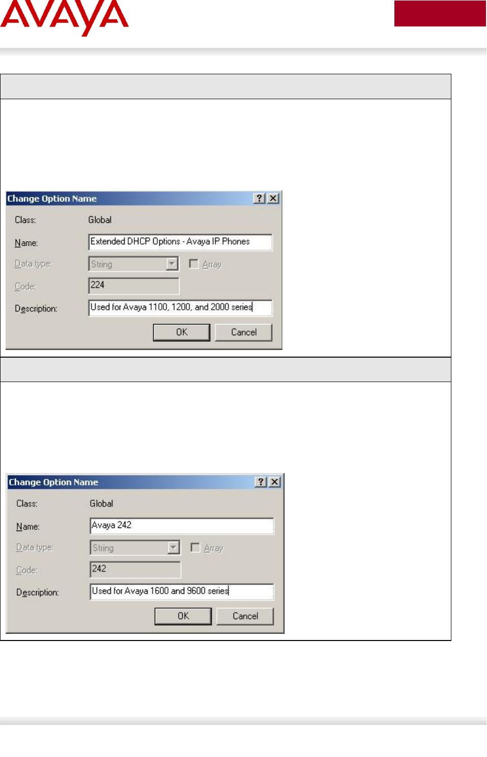
Avaya Inc. – External Distribution
100
avaya.com
Aug 2012
Windows 2003 Server Step 4 – Create DHCP option 224
Select Add again and fill in the information as shown below for the DHCP option with the identifier
set to 224.
Name: Any name you like
Set Date type: String
Code: 224
Description: Add any comments if you like
Windows 2003 Server Step 5 – Create DHCP option 242
Select Add again and fill in the information as shown below for the DHCP option with the identifier
set to 242.
Name: Any name you like
Set Date type: String
Code: 242
Description: Add any comments if you like
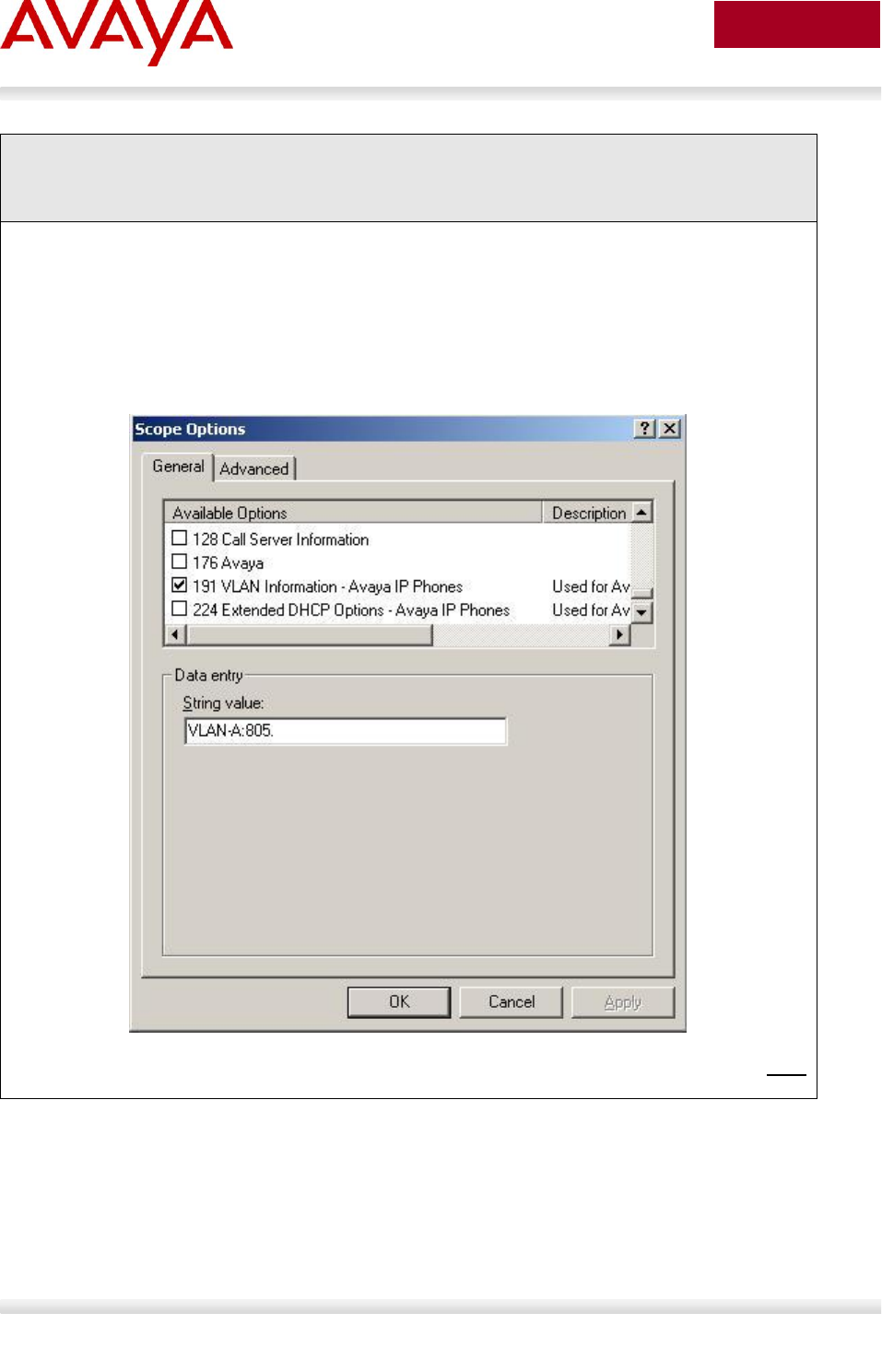
Avaya Inc. – External Distribution
101
avaya.com
Aug 2012
Windows 2003 Server Step 6 – Right-click Scope Option from the data VLAN DHCP scope
and select Configure Options. Scroll down to the DHCP Options you just created and
check off the box to enable the 191 Option
Add the appropriate IP address scope, default router, and other various DHCP options for the
data VLAN. Once you complete this step, you can then add the required DHCP options for the
Avaya IP Phone VLAN information. The example below shows the DHCP scope for the Data
VLAN using DHCP Option 191 for the Avaya 1100, 1200, or 2000 series IP Phones. The example
below shows the string value pertaining for the Data VLAN where the following string is added to
set the Avaya IP phone to tag the voice VLAN using VLAN ID 805:
VLAN-A:805.
There must be a colon (:) separating the Hardware Revision from the VLAN ID. The string must
also end in a period (.)
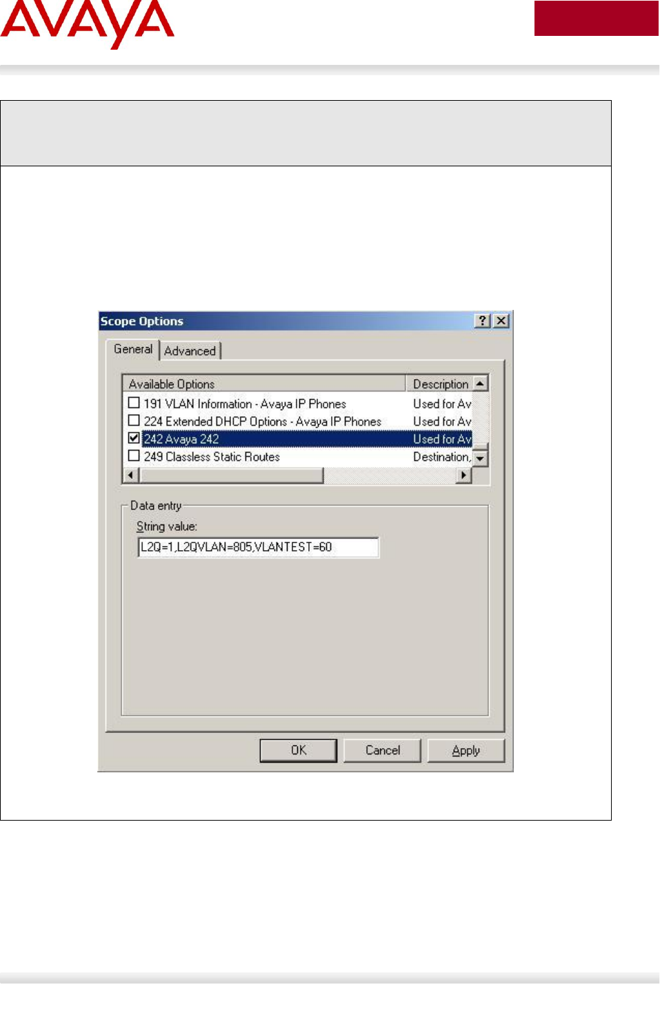
Avaya Inc. – External Distribution
102
avaya.com
Aug 2012
Windows 2003 Server Step 7 – Right-click Scope Option from the data VLAN DHCP scope
then select Configure Options. Scroll down to the DHCP Options you just created and
check off the box to enable the 242 Option
Add the appropriate IP address scope, default router, and other various DHCP options for the
data VLAN. Once you complete this step, you can then add the required DHCP options for the
Avaya IP Phone VLAN information. The example below shows the DHCP scope for the Data
VLAN using DHCP Option 242 for the Avaya 1600 or 9600 series IP Phones. The example below
shows the string value pertaining for the Data VLAN where the following string is added to set the
Avaya IP phone to tag the voice VLAN using VLAN ID 60:
L2Q=1,L2QVLAN=805,VLANTEST=60
The string must have a comma (,) between each parameter with no spaces.
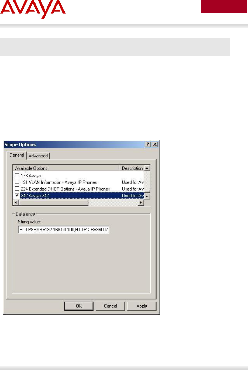
Avaya Inc. – External Distribution
103
avaya.com
Aug 2012
Windows 2003 Server Step 8 – Right-click Scope Option from the voice VLAN DHCP scope
and select Configure Options. Scroll down to the DHCP Options you just created and
check off the box to enable the 242 Option
Add the appropriate IP address scope, default router, and other various DHCP options for the
voice VLAN. Once you complete this step, you can then add the required DHCP options for the
Avaya IP Phone VLAN information. The example below shows the DHCP scope for the Voice
VLAN using DHCP Option 242 for the Avaya 9600 series IP Phones as used in this example. The
example below shows the string value pertaining for the Voice VLAN assuming the Avaya 9600
IP Phones are using H.323 and retrieving the configuration file using HTTP from the directory
9600/96xxH323_032910. In this directory, it should contain the appropriate files, assuming the
Avaya 9600 series is used, it should contain the 96xxupgrade.txt and 46xxsettings.txt files
With a provision server using HTTP
o HTTPSRVR=192.168.50.100,HTTPDIR= 9600/96xxH323_032910
Without a provision server:
o MCIPADD=10.30.30.20,VLANTEST=60
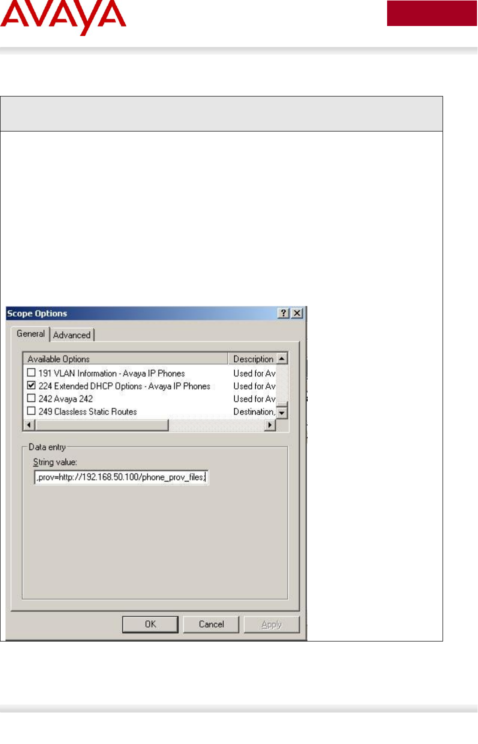
Avaya Inc. – External Distribution
104
avaya.com
Aug 2012
Windows 2003 Server Step 9 – Right-click Scope Option from the voice VLAN DHCP scope
and select Configure Options. Scroll down to the DHCP Options you just created and
check off the box to enable the 224 Option
Add the appropriate IP address scope, default router, and other various DHCP options for the
voice VLAN. Once you complete this step, you can then add the required DHCP options for the
Avaya IP Phone VLAN information. The example below shows the DHCP scope for the Voice
VLAN using DHCP Option 224 for the Avaya 1100 or 1200 series IP Phones. The example below
shows the string value pertaining for the Voice VLAN assuming the Avaya 1100 or 1200 IP
Phones use HTTP to get it’s provisioning files via the directory named phone_prov_files
With a provision server using HTTP
o Nortel-i2004-B,prov=http://192.168.50.100/phone_prov_files;
With a provision server using TFTP
o Nortel-i2004-B,prov=192.168.50.100/phone_prov_files;
Without a provision server:
o Nortel-i2004-B,s1=10.88.2.20;p1=4100;a1=1;r1=5;s2=10.88.2.20;p1=4100;
a1=1;r1=5;
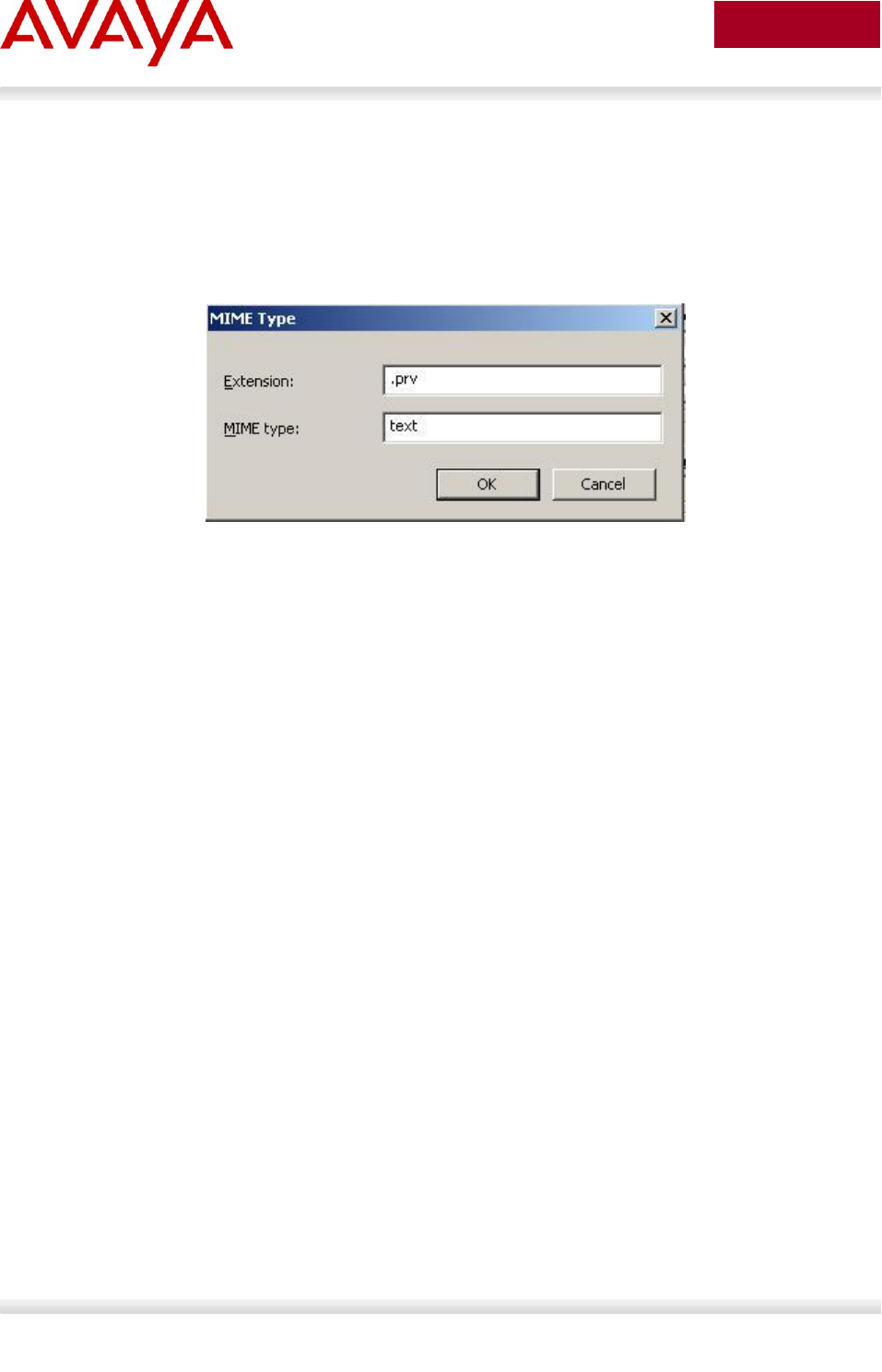
Avaya Inc. – External Distribution
105
avaya.com
Aug 2012
Please note that if using a Windows 2003 server, it may not associate the Avaya
1100/1200 series provision file extention of .prv with text files. To change this, open
Windows 2003 Internet Information Services (IIS) Manager and under the name of your
IIS server, go to Web Sites -> Default Web Site -> phone_prov_files -> Properties (in
our example, phone_prov_files is the name of the directory storing the Avaya 1100/1200
series provision files). Next, go to HTTP Headers -> MIME Types -> New and under
Extention, enter .prv and under MIME Type, enter text.

Avaya Inc. – External Distribution
106
avaya.com
Aug 2012
3. Avaya IP Deskphones
Avaya offers a variety of IP Deskphones. The following sections highlight the major features of each of
these series of phones along with information on how to access the configuration menus.
3.1 2000 Series IP Deskphones
3.1.1 Feature Comparison
Feature
Avaya 2000 Series IP Deskphones
IP Phone
20011
IP Phone
20021
IP Phone
20041
2007 IP
Deskphone
Display Size / Type
3x24
Character
LCD
4x24
Character
LCD
8x24
Character
LCD
320x240
Pixels Color
Touch screen
LCD
# of Lines
1
4
6+ Varies
w/config
6+ Varies
w/config
Headset Jack
0
1
1
1
Handsfree
Listen
only
Yes
Yes
Yes
802.3af PoE Class
Class 2
Class 2
Class 2
Class 3
Two Port Switch
No
Yes
Yes
Yes
Gigabit Ethernet
No
No
No
No
USB Ports
0
0
0
1
Support for
Expansion Module
Attachment
No
Yes (Current
200x KEM)
Yes (Current
200x KEM)
No
Bluetooth Headset
No
No
No
No
XAS (Application
Gateway) Support
Yes
Yes
Yes
Yes
EAP (802.1x)
Yes
Yes
Yes
(Phase II
only)
Yes
802.1AB
Yes
Yes
(Phase II
only)
Yes
(Phase II
only)
Yes
Table 1: Avaya IP Deskphones – 2000 Series
1
The IP Phone 2001, IP Phone 2002 and IP Phone 2002 are no longer manufactured.
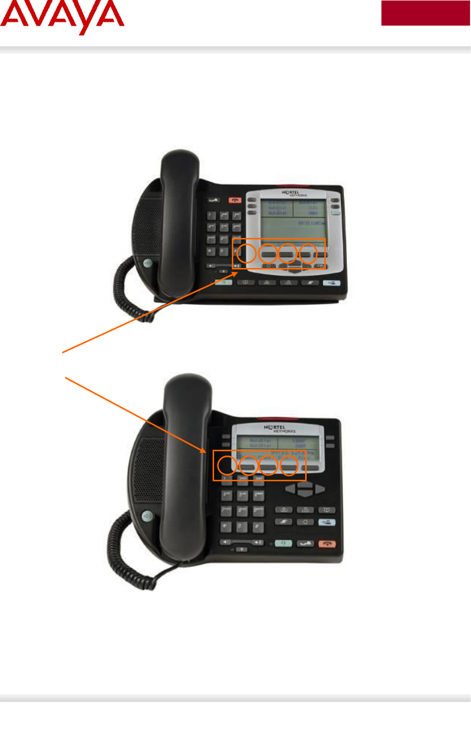
Avaya Inc. – External Distribution
107
avaya.com
Aug 2012
3.1.2 Accessing the Configuration Menu (2001/2002/2004)
To access the configuration menu power cycle the IP Phone 2001/2002/2004 and then wait until Nortel
appears on the LCD panel. At this point, press the following keys in order from 1 to 4: Function key 1,
Function key 2, Function key 3, and finally Function key 4.
Figure 3: IP Phone 2004 Access Configuration Menu
Figure 4: IP Phone 2002 Access Configuration Menu
To power cycle the IP Phone 2004 via the front panel, press the following keys in order from 1 to 9: Mute
key, up Navigation key, down Navigation key, up Navigation key, down Navigation key, up Navigation
key, Mute, 9, and finally the Goodbye key.
Function Keys
1
2
3
4
1
2
3
4
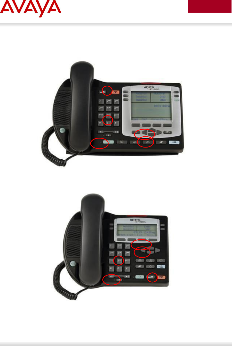
Avaya Inc. – External Distribution
108
avaya.com
Aug 2012
To power cycle the IP Phone 2001 via the front panel, press the following keys in order from 1 to 9: # key,
up Navigation key, down Navigation key, up Navigation key, down Navigation key, up Navigation key, #,
9, and finally the Goodbye key.
Figure 5: IP Phone 2004 Power Cycle Phone Set
Figure 6: IP Phone 2002 Power Cycle Phone Set
1,
2,
3
8
9
1,
2,
3
8
9

Avaya Inc. – External Distribution
109
avaya.com
Aug 2012
3.1.3 Configuration Menu on Phase II IP Phone 2001, Phase
II IP Phone 2002 and Phase II IP Phone 2004
The single-line based configuration menu structure below presents the complete configuration menu now
available on the Phase II IP Phone 2001, Phase II IP Phone 2002 and Phase II IP Phone 2004:
EAP Enable?[0-N,1-Y]:0
if “1”
DeviceID:[ ]
Password:
LLDP Enable?[0-N,1-Y]:0
DHCP? [0-N, 1-Y]:1
if “0”
SET IP: xxx.xxx.xxx.xxx
NETMSK: xxx.xxx.xxx.xxx
DEF GW: xxx.xxx.xxx.xxx
S1 IP: xxx.xxx.xxx.xxx
S1 PORT:
S1 ACTION:
S1 RETRY COUNT:
S2 IP: xxx.xxx.xxx.xxx
S2 PORT:
S2 ACTION:
S2 RETRY COUNT:
else if “1”
DHCP:0-Full,1-Partial:1
if “1”
S1 IP: xxx.xxx.xxx.xxx
S1 PORT:
S1 ACTION:
S1 RETRY COUNT:
S2 IP: xxx.xxx.xxx.xxx
S2 PORT:
S2 ACTION:
S2 RETRY COUNT:
Speed[0-A,1-10,2-100]:0
if “1” or “2”
Duplex[0-A,1-F,2-H]:0
Cfg XAS?[0-N, 1-Y]:1
if “1”
XAS IP: xxx.xxx.xxx.xxx
Voice 802.1Q[0-N,1-Y]:1
if “1”
VOICE VLAN?[0-N,1-Y]:0
if “1”
VLAN Cfg?0-Auto,1-Man :1
The VLAN Cfg menu is only presented if DHCP is provisioned to “Partial” or “Full”

Avaya Inc. – External Distribution
110
avaya.com
Aug 2012
above or if LLDP is enabled above.
if “0”
LLDP MED? [0-N, 1-Y] :0
The LLDP MED menu is only presented if LLDP is enabled above.
if “0”
LLDP VLAN? [0-N,1-Y] :0
The LLDP VLAN menu is only presented if LLDP is enabled above.
if “0”
DHCP? [0-N, 1-Y] :0
The DHCP menu is only presented if DHCP is provisioned to
“Partial” or “Full” above.
else if “1”
VOICE VLAN ID :
VLANFILTER?[0-N, 1-Y] :0
Ctrl pBits[0-7,8-Au] :8
Media pBits[0-7,8-Au] :8
PC Port? [0-OFF,1-ON] :1 This menu item, and submenus, are not available on the IP Phone 2001.
if “1”
Speed[0-A,1-10,2-100]:0
if “1” or “2”
Duplex[0-A,1-F,2-H]:0
Data 802.1Q[0-N,1-Y]:1
if “1”
DATA VLAN? [0-N, 1-Y]:0
if “1”
DATA VLAN Cfg?0-A,1-M:0
This DATA VLAN Cfg menu item is only presented if LLDP is enabled above.
if “1”
DATA VLAN ID:
Data pBits[0-7,8-Au] :8
PCUntagAll?[0-N,1-Y]:0
Cached IP? [0-N, 1-Y]:0
This Cached IP menu item is only presented if DHCP is provisioned to “Yes” above and Voice
VLAN is not provisioned as “Auto”.
GARP Ignore?[0-N,1-Y]:0
PSK SRTP?[0-N, 1-Y]:0
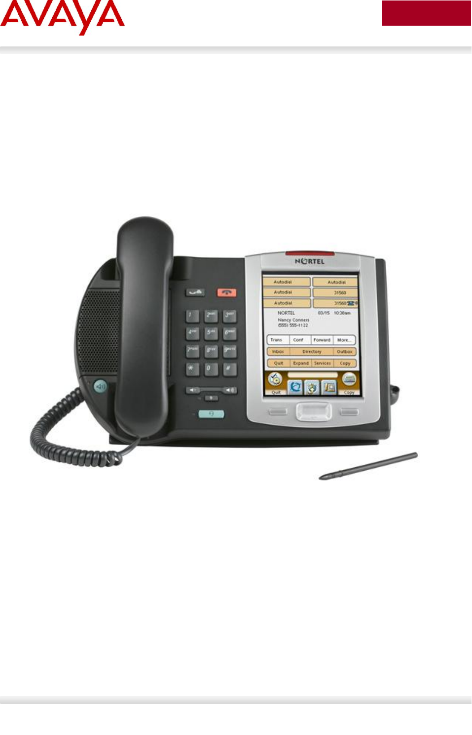
Avaya Inc. – External Distribution
111
avaya.com
Aug 2012
3.1.4 Accessing the Configuration Menu (2007 IP
Deskphone)
To access the configuration menu, power cycle the 2007 IP Deskphone and when the Avaya logo
appears in the middle of the display, immediately press the following key in sequence: 0, 0, 7, and star
(*). If prompted for “Enter Administration Password:”, then press the following keys in sequence: 2, 6, 5, 6,
7, *, 7, 3, 8, OK. Using Navigation Keys scroll down/up to select the configuration options. As an
alternative, use the USB port on the back of the IP Phone to use a mouse to scroll and select
configuration options.
Figure 7: IP Phone 2007 Phone Set
3.1.5 Configuration Menu on the 2007 IP Deskphone
The full-screen based configuration menu structure below presents the complete configuration menu available on
the 2007 IP Deskphone as of UNIStim 4.2 (0621C7G). For other releases of software, please refer to the associated
Product Bulletin or ReadMe File.
EAP Mode: [Disable, MD5, PEAP, TLS]
ID 1:
ID 2:
Password:
Enable 802.1ab (LLDP): []
DHCP: [No, Yes]
Set IP: xxx.xxx.xxx.xxx

Avaya Inc. – External Distribution
112
avaya.com
Aug 2012
Net Mask: xxx.xxx.xxx.xxx
Gateway: xxx.xxx.xxx.xxx
DNS1 IP: xxx.xxx.xxx.xxx
DNS2 IP: xxx.xxx.xxx.xxx
CA Server:
Domain Name:
Hostname:
S1 IP: xxx.xxx.xxx.xxx
Port:
S1 Action:
Retry:
S1 PK: FFFFFFFFFFFFFFFF
S2 IP: xxx.xxx.xxx.xxx
Port:
S2 Action:
Retry:
S2 PK: FFFFFFFFFFFFFFFF
Ntwk Port Speed: [Auto, 10BT, 100BT]
Ntwk Port Duplex: [Auto, Force Full, Force Half]
Phone Mode [Hidden, Full, Reduced]
XAS Mode [Text Mode, Graphical, Full Screen, Secure Graphical, Secure Full Screen]
XAS IP: xxx.xxx.xxx.xxx
Port:
Enable Voice 802.1Q: []
VoiceVLAN: [No VLAN, Auto, Enter VLAN ID]
The Auto option in the VoiceVLAN menu is only available if DHCP is provisioned to “Yes” above or if LLDP is
enabled above, respectively.
VLAN Filter : []
Ctrl Priority Bits: [Auto, 0, 1, 2, 3, 4, 5, 6, 7]
Media Priority Bits: [Auto, 0, 1, 2, 3, 4, 5, 6, 7]
Enable Avaya Auto QoS: []
DSCP Override: [] This DSCP Override menu item is only presented if “Enable 802.1ab (LLDP)” is enabled above
and “Control DSCP” or “Media DSCP” are not manually set below
Control DSCP: xx
Media DSCP: xx
Enable PC Port: []
PC Port Speed: [Auto, 10BT, 100BT]
PC Port Duplex: [Auto, Force Full, Force Half]
Enable Data 802.1Q: []
DataVLAN: [No VLAN, Enter VLAN ID]
Data Priority Bits: [Auto, 0, 1, 2, 3, 4, 5, 6, 7]
PC-Port Untag All: []
Enable Stickiness []
Cached IP: [] This Cached IP menu item is only presented if DHCP is provisioned to “Yes” above.
Ignore GARP: []
Enable SRTP PSK: []
SRTP PSK Payload ID: [96, 115, 120]
Provision: xxx.xxx.xxx.xxx

Avaya Inc. – External Distribution
113
avaya.com
Aug 2012
Provision Zone ID:
The 2007 IP Deskphone contains a password protection mechanism to lock out access to the Local Tools
menu including the Network Configuration menu. If enabled, access to the Local Tools menu is password
protected and the password is prompted by a pop up window. One must type the password from the dial
pad and press the center of the navigation cluster (enter key) to enter the Network Configuration menu.
The default password is 26567*738 (color*set), but this password can be changed by the system
administrator.
When an incorrect password is entered, the Local Tools menu is not opened.
To thwart password guessing, only 3 incorrect password entries in a row are allowed. After the 3rd
incorrect entry, the password entry is ignored for 5 minutes. During this period of time, the password
prompt is displayed and the entered digits accepted; however, the phone will not process the incoming
digits. The password prompt window simply closes and the behavior is identical to that of an incorrect
password entry. The user will assume the incorrect password has been entered and try again. Thus even
if the correct password is guessed during the 5 minute period, it will be ignored. This effectively reduces
the guess entry rate to 3 guesses every 5 minutes.
Once the password has been entered, access to the Local Tools menu remains active for 5 minutes.
During the 5 minutes, the menu can be freely navigated, exited and entered without being prompted
again for the password. When the 5 minutes expires, the menu is closed. The password must be
reentered to access the Local Tools menu.
Avaya Inc. – External Distribution
114
avaya.com
Aug 2012
3.2 1100 Series IP Deskphones
3.2.1 Feature Comparison
Feature
Avaya 1100 Series IP Deskphone
1110 IP
Deskphone
1120E IP
Deskphone
1140E IP
Deskphone
1150E IP
Deskphone
1165E IP
Deskphone
Display Size / Type
144x32
Pixels
Graphical
LCD
240x80
Pixels
Grayscale
LCD
240x160
Pixels
Grayscale
LCD
240x160
Pixels
Grayscale
LCD
320x240
Pixels 24-bit
Color LCD
Feature Keys
(Excluding Enter +
NAV)
12
22
24
30
30
# of Lines
1
4
6+ Varies
w/config
6+ Varies
w/config
8+ Varies
w/config
Headset Jack
0
1
1
1
1
Handsfree
Listen only
Yes
Yes
Yes
Yes
802.3af PoE Class
Class 2
Class 2
Class 2
Class 3
Class 2
Two Port Switch
Yes
Yes
Yes
Yes
Yes
Gigabit Ethernet
No
Yes
Yes
Yes
Yes
USB Ports
0
1
1
1
1
Support for
Expansion Module
Attachment
No
Yes
Yes
Yes
Yes
Bluetooth Headset
No
No
Yes
Yes (Agent
only)
Yes
XAS (Application
Gateway) Support
Yes
Yes
Yes
Yes
Yes
EAP (802.1x)
Yes
Yes
Yes
Yes
Yes
802.1AB
No
Yes
Yes
Yes
Yes
Table 2: Avaya IP Deskphones – 1100 Series
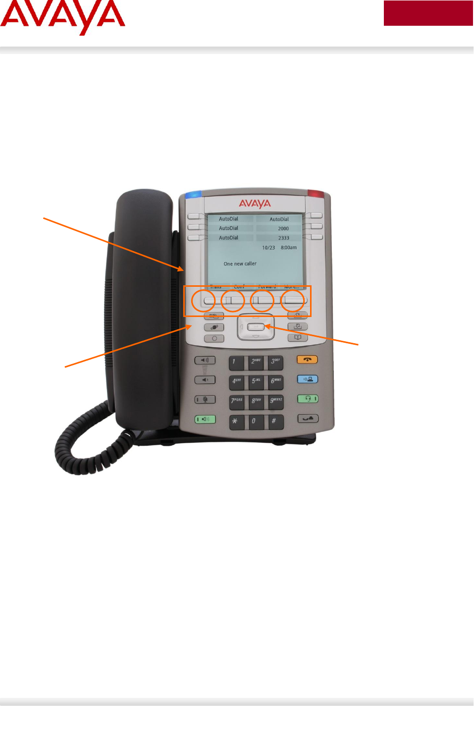
Avaya Inc. – External Distribution
115
avaya.com
Aug 2012
3.2.2 Accessing the Configuration Menu
To access the configuration menu, power cycle the 11xx IP Deskphone and when the Avaya logo
appears in the middle of the display, immediately press the four feature keys at the bottom of the display
in sequence from left to right. If prompted for “Enter Administration Password:”, then press the following
keys in sequence: 2, 6, 5, 6, 7, *, 7, 3, 8, Down. Use the Navigation Keys scroll down/up to select
configuration options. As an alternative, use the USB port on the back of the IP Deskphone to use a
mouse to scroll and select configuration options.
Figure 8: 1100 Series IP Deskphone Setup
You can also configure the 1100 Series IP Deskphone by pressing the Services key twice and select
option 3 Network Configuration.
Function Keys
1
2
3
4
Navigation Keys
Services keys

Avaya Inc. – External Distribution
116
avaya.com
Aug 2012
3.2.3 Configuration Menu on the 1120E/1140E/1150E/1165E
IP Deskphone
The full-screen based configuration menu structure below presents the complete configuration menu
available on the 1120E, 1140E, 1150E and 1165E IP Deskphones running UNIStim 4.2 software
(062xC7M). For other versions of software, please refer to the associated Product Bulletin or ReadMe
File.
EAP Mode: [Disable, MD5, PEAP, TLS]
ID 1:
ID 2:
Password:
Enable VPN: []
Protocol:
Mode:
Authentication:
PSK User ID:
PSK Password:
XAUTH Method:
XAUTH User ID:
XAUTH Password:
VPN Server 1: xxx.xxx.xxx.xxx
VPN Server 2: xxx.xxx.xxx.xxx
VPN DSCP:
VPN MOTD Timer:
Enable 802.1ab (LLDP): []
DHCP: [No, Yes]
Set IP: xxx.xxx.xxx.xxx
Net Mask: xxx.xxx.xxx.xxx
Gateway: xxx.xxx.xxx.xxx
DNS1 IP: xxx.xxx.xxx.xxx
DNS2 IP: xxx.xxx.xxx.xxx
Local DNS IP: xxx.xxx.xxx.xxx
CA Server:
Domain Name:
Hostname:
S1 IP: xxx.xxx.xxx.xxx
Port:
S1 Action:
Retry:
S1 PK: FFFFFFFFFFFFFFFF
S2 IP: xxx.xxx.xxx.xxx
Port:
S2 Action:
Retry:
S2 PK: FFFFFFFFFFFFFFFF
Ntwk Port Speed: [Auto, 10BT, 100BT]
Ntwk Port Duplex: [Auto, Force Full, Force Half]

Avaya Inc. – External Distribution
117
avaya.com
Aug 2012
XAS Mode: [Text Mode, Graphical, Secure Graphical] This parameter is called “Graphical XAS” on the 1165E IP
Deskphone.
XAS IP: xxx.xxx.xxx.xxx
XAS Port:
Enable Voice 802.1Q: []
VoiceVLAN: [No VLAN, Auto, Enter VLAN ID]
The Auto option in the VoiceVLAN menu is only available if DHCP is provisioned to “Yes” above or if LLDP is
enabled above
VLAN Filter : []
Ctrl Priority Bits: [Auto, 0, 1, 2, 3, 4, 5, 6, 7]
Media Priority Bits: [Auto, 0, 1, 2, 3, 4, 5, 6, 7]
Enable Avaya Auto Qos: []
DSCP Override: [] This DSCP Override menu item is only presented if “Enable 802.1ab (LLDP)” is enabled above
and “Control DSCP” or “Media DSCP” are not manually set below
Control DSCP: xx
Media DSCP: xx
Enable PC Port: []
PC Port Speed: [Auto, 10BT, 100BT]
PC Port Duplex: [Auto, Force Full, Force Half]
Enable Data 802.1Q: []
DataVLAN: [No VLAN, Enter VLAN ID]
Data Priority Bits: [Auto, 0, 1, 2, 3, 4, 5, 6, 7]
PC-Port Untag All: []
Enable Stickiness []
Cached IP: [] This Cached IP menu item is only presented if DHCP is provisioned to “Yes”.
Ignore GARP: []
Enable SRTP PSK: []
SRTP PSK Payload ID: [96, 115, 120]
Provision: xxx.xxx.xxx.xxx
Provision Zone ID:
Enable Bluetooth: [Yes, No] This Bluetooth menu item is on the 1140E, 1150E, and 1165E only.
The 1120E, 1140E, 1150E and 1165E IP Deskphones contain a password protection mechanism to lock
out access to the Local Tools menu including the Network Configuration menu. If enabled, access to the
Local Tools menu is password protected and the password is prompted by a pop up window. One must
type the password from the dial pad and press the center of the navigation cluster (enter key) to enter the
Network Configuration menu. The default password is 26567*738 (color*set), but this password can be
changed by the system administrator.
When an incorrect password is entered, the Local Tools menu is not opened.
To thwart password guessing, only 3 incorrect password entries in a row are allowed. After the 3rd
incorrect entry, the password entry is ignored for 5 minutes. During this period of time, the password
prompt is displayed and the entered digits accepted; however, the phone will not process the incoming
digits. The password prompt window simply closes and the behavior is identical to that of an incorrect
password entry. The user will assume the incorrect password has been entered and try again. Thus even
if the correct password is guessed during the 5 minute period, it will be ignored. This effectively reduces
the guess entry rate to 3 guesses every 5 minutes.

Avaya Inc. – External Distribution
118
avaya.com
Aug 2012
Once the password has been entered, access to the Local Tools menu remains active for 5 minutes.
During the 5 minutes, the menu can be freely navigated, exited and entered without being prompted
again for the password. When the 5 minutes expires, the menu is closed. The password must be
reentered to access the Local Tools menu.

Avaya Inc. – External Distribution
119
avaya.com
Aug 2012
3.3 1200 Series IP Deskphone
3.3.1 Feature Comparison
Feature
Avaya 1200 Series IP Deskphone
IP Phone
1210
IP Phone
1220
IP Phone
1230
Display Size / Type
3x24
characters
LCD
5x25
characters
LCD
9x25
characters
LCD
Feature Keys
(Excluding Enter +
NAV)
14
22
28
# of Lines
1
4+ Varies
w/config
6+ Varies
w/config
Headset Jack
1
1
1
Handsfree
Yes
Yes
Yes
802.3af PoE Class
Class 2
Class 2
Class 2
Two Port Switch
Yes
Yes
Yes
Gigabit Ethernet
No
No
No
USB Ports
0
0
0
Support for
Expansion Module
Attachment
No
Yes (LED &
LCD)
Yes (LED &
LCD)
Bluetooth Headset
No
No
No
XAS (Application
Gateway) Support
No
No
No
EAP (802.1x)
Yes
Yes
Yes
802.1AB
Yes
Yes
Yes
Table 3: Avaya IP Phone Sets – 1200 series
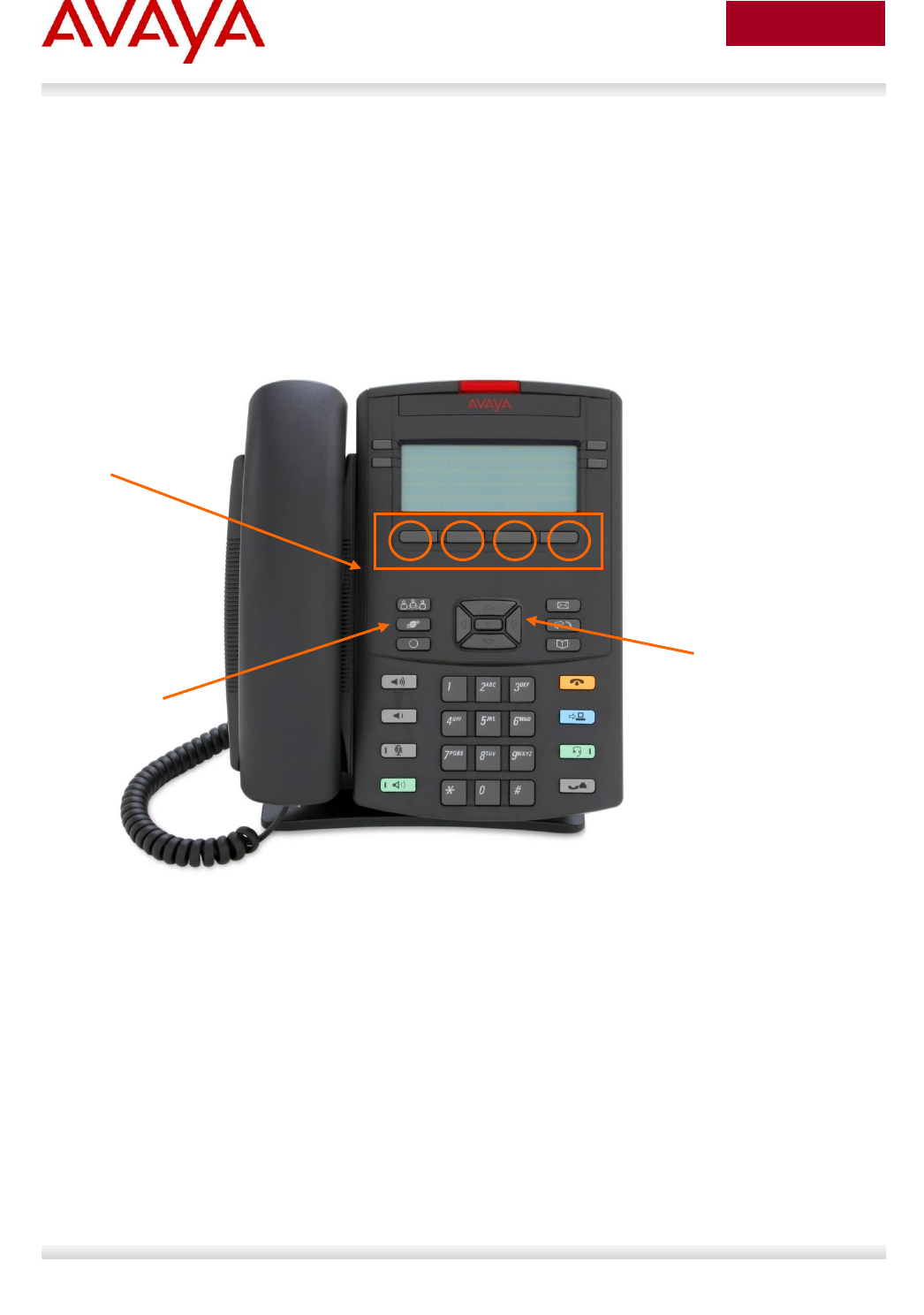
Avaya Inc. – External Distribution
120
avaya.com
Aug 2012
3.3.2 Access the Configuration Menu
To access the configuration menu, power cycle the IP Phone 12x0 and when the Avaya logo appears in
the middle of the display, immediately press the four feature keys at the bottom of the display in sequence
from left to right. If prompted for “Enter Administration Password:”, then press the following keys in
sequence: 2, 6, 5, 6, 7, *, 7, 3, 8, Down. Use the Navigation Keys scroll down/up to select configuration
options.
Figure 9: 1200 Series IP Deskphone Setup
You can also configure the 1200 Series IP Deskphone by pressing the Services key twice and select
option 3 Network Configuration.
Function Keys
1
2
3
4
Navigation Keys
Services key

Avaya Inc. – External Distribution
121
avaya.com
Aug 2012
3.3.3 Configuration Menu on IP Phone 12xx Series and IP
Phone 1110
The single-line based configuration menu structure below presents the complete configuration menu
available with UNIStim 4.2 software (062xC7M) on the 1110 and 1200 Series IP Deskphones. For other
releases of software, please refer to the associated Product Bulletin or ReadMe File.
EAP[0-N,1-M, 2-P, 3-T]:0
if “1” or “2” or “3”
ID 1: [ ]
also if “1” or “2”
ID 2: [ ]
Password: [*******]
LLDP Enable?[0-N,1-Y]:0
DHCP? [0-N,1-Y]:1
if “0”
Set IP: xxx.xxx.xxx.xxx
Netmsk: xxx.xxx.xxx.xxx
Def GW: xxx.xxx.xxx.xxx
DNS1 IP: xxx.xxx.xxx.xxx
DNS2 IP: xxx.xxx.xxx.xxx
CA Server:
Domain Name:
Hostname:
S1 IP: xxx.xxx.xxx.xxx
S1 Port:
S1 Action:
S1 Retry Count:
S2 IP: xxx.xxx.xxx.xxx
S2 Port:
S2 Action:
S2 Retry Count:
Speed[0-A,1-10,2-100]:0
if “1” or “2”
Duplex[0-A,1-F,2-H]:0
Cfg XAS? [0-N, 1-Y]:1
if “1”
XAS IP: xxx.xxx.xxx.xxx
Voice 802.1Q[0-N,1-Y]:1
if “1”
Voice VLAN?[0-N,1-Y]:0
if “1”
VLAN Cfg ?0-Auto,1-Man :1
This VLAN Cfg menu is only presented if DHCP is provisioned to “Y” above or if LLDP Enabled is
provisioned to “Y” above.
if “1”
VLAN ID :
VLAN Filter?[0-N,1-Y] :0
Ctrl pBits[0-7,8-Au] :8
Media pBits[0-7,8-Au] :8
Avaya QOS? [0-N,1-Y]:0

Avaya Inc. – External Distribution
122
avaya.com
Aug 2012
DSCP Ovride [0-N,1-Y]:0 This DSCP Override menu item is only presented if “LLDP Enable?” is enabled
above and neither the “Control DSCP” or “Media DSCP” are not manually set below
CTRL DSCP [0-63]: xx
Media DSCP [0-63]: xx
PC Port ? [0-Off,1-On] :1
if “1”
Speed[0-A,1-10,2-100]:0
if “1” or “2”
Duplex[0-A,1-F,2-H]:0
Data 802.1Q[0-N,1-Y]:1
if “1”
VLAN ID :
Data pBits[0-7,8-Au] :8
PCUntagAll? [0-N,1-Y]:1
Stickiness? [0-N,1-Y]:1
Cached IP? [0-N, 1-Y]:0 This Cached IP menu item is only presented if DHCP is provisioned to “Y” above
GARP Ignore?[0-N,1-Y]:0
SRTP PSK? [0-N, 1-Y]:0
PayID[0-96,1-115,2-120]0
Prov: xxx.xxx.xxx.xxx
Prov Zone ID:
End of Menu
The 1110, 1210, 1220 and 1230 IP Deskphones contain a password protection mechanism to lock out
access to the Local Tools menu including the Network Configuration menu. If enabled, access to the
Local Tools menu is password protected and the password is prompted by a pop up window. One must
type the password from the dial pad and press the center of the navigation cluster (enter key) to enter the
Network Configuration menu. The default password is 26567*738 (color*set), but this password can be
changed by the system administrator.
When an incorrect password is entered, the Local Tools menu is not opened.
To thwart password guessing, only 3 incorrect password entries in a row are allowed. After the 3rd
incorrect entry, the password entry is ignored for 5 minutes. During this period of time, the password
prompt is displayed and the entered digits accepted; however, the phone will not process the incoming
digits. The password prompt window simply closes and the behavior is identical to that of an incorrect
password entry. The user will assume the incorrect password has been entered and try again. Thus even
if the correct password is guessed during the 5 minute period, it will be ignored. This effectively reduces
the guess entry rate to 3 guesses every 5 minutes.
Once the password has been entered, access to the Local Tools menu remains active for 5 minutes.
During the 5 minutes, the menu can be freely navigated, exited and entered without being prompted
again for the password. When the 5 minutes expires, the menu is closed. The password must be
reentered to access the Local Tools menu.

Avaya Inc. – External Distribution
123
avaya.com
Aug 2012
3.4 Restore to Factory Defaults (applies to 1100-
Series, 1200-Series, and 2007 IP Deskphones)
The UNIStim software release 3.0 for IP Deskphones introduced the ability to restore an IP Deskphone to
a “factory default” configuration. This can be useful when redeploying an IP Deskphone from one location
to another, when starting to use an IP Deskphone with unknown history, or to reset to a known baseline
configuration.
With UNIStim software release 3.0, and greater, the following keypad sequence is used to reset all
provisioning parameters to a “factory default”:
[*][*][7][3][6][3][9][MAC][#][#]
Where MAC corresponds to the MAC address of the IP Deskphone which can be found on a label on
the back of the IP Deskphone.
Since a MAC address can contain the letters A through F, the letters A, B and C can be entered via
the [2] key on the dialpad, and letters D, E and F can be entered via the [3] key.
For example, an IP Deskphone with MAC address 00:19:E1:E2:17:12 would be reset to “factory
default” when the sequence **73639001931321712## is entered on the keypad.
Please note that the keypad sequence will only be accepted by the phone after the IP Deskphone has
finished its boot-up procedure.

Avaya Inc. – External Distribution
124
avaya.com
Aug 2012
3.5 1600 Series IP Deskphones
3.5.1 Feature Comparison
Feature
Avaya 1600 Series IP Deskphone
1603-I IP
Deskphone
1603SW-I IP
Deskphone
1608-I IP
Deskphone
1616-I IP
Deskphone
Display Size / Type
128x25 Pixel
Mono LCD
128x25 Pixel
Mono LCD
181x40 Pixel
Mono LCD
181x56 Pixel
Mono LCD
# of Lines
3
3
8
16
Headset Jack
0
0
1
1
Handsfree
Listen only
Listen only
Yes
Yes
802.3af PoE Class
Class 2
Class 2
Class 2
Class 2
Two Port Switch
No
Yes
Yes
Yes
Gigabit Ethernet
No
No
No
No
USB Ports
0
0
0
0
Support for
Expansion Module
Attachment
No
No
No
Yes
Bluetooth Headset
No
No
No
No
WML Support
No
No
No
No
EAP (802.1x)
Yes
Yes
Yes
Yes
802.1AB
No
No
No
No
Table 4: Avaya IP Phone Sets – 1600 series
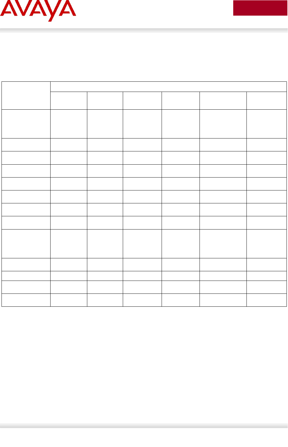
Avaya Inc. – External Distribution
125
avaya.com
Aug 2012
3.6 9600 Series IP Deskphones
3.6.1 Feature Comparison
Feature
Avaya 9600 Series IP Deskphone (1 of 2)
9608 IP
Deskphone
9611G IP
Deskphone
9620L IP
Deskphone
9620C IP
Deskphone
9621G IP
Deskphone
9630G IP
Deskphone
Display Size /
Type
181x120
Pixels Color
LCD
320x240
Pixels Color
LCD
320x160
Pixels
Grayscale
LCD
320x160
Pixels Color
LCD
480x272 Pixels
Color
Touchscreen
LCD
320x240
Pixels
Grayscale
LCD
# of Lines
8
8
1
1
11
6
Headset Jack
1
1
1
1
1
1
Handsfree
Yes
Yes
Yes
Yes
Yes
Yes
802.3af PoE
Class
Class 1
Class 1
Class 1
Class 2
Class 2
Class 2
Two Port Switch
Yes
Yes
Yes
Yes
Yes
Yes
Gigabit Ethernet
No
Yes
No
No
Yes
Yes
USB Ports
0
1
0
1
0
1
Support for
Expansion
Module
Attachment
No
Yes
No
No
Yes
Yes
Bluetooth
Headset
No
No
No
No
No
No
WML Support
Yes
Yes
Yes
Yes
Yes
Yes
EAP (802.1x)
Yes
Yes
Yes
Yes
Yes
Yes
LLDP (802.1AB)
Yes
Yes
Yes
Yes
Yes
Yes
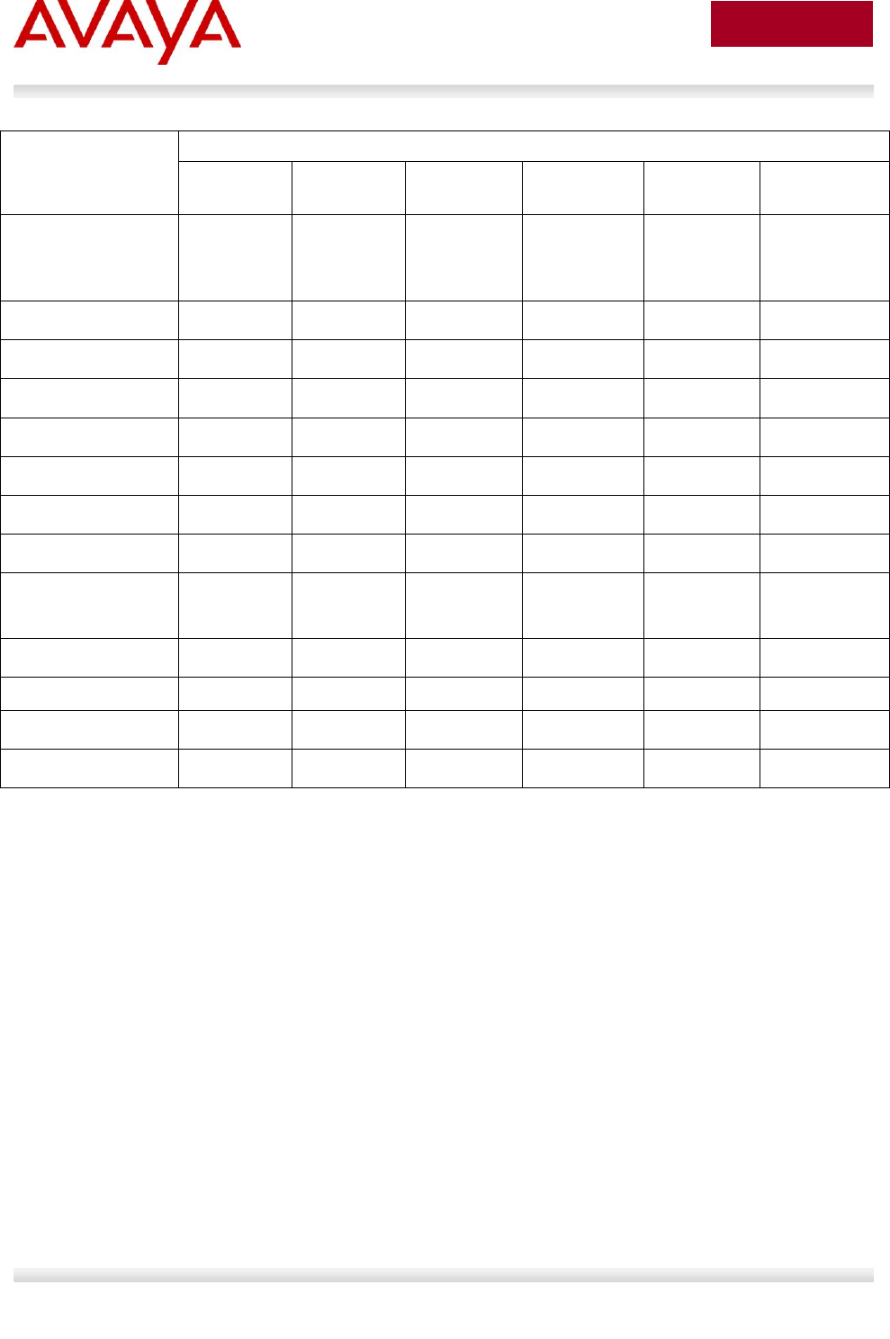
Avaya Inc. – External Distribution
126
avaya.com
Aug 2012
Feature
Avaya 9600 Series IP Deskphone (2 of 2)
9640 IP
Deskphone
9640G IP
Deskphone
9641G IP
Deskphone
9650 IP
Deskphone
9650C IP
Deskphone
9670G IP
Deskphone
Display Size / Type
320x240
Pixels Color
LCD
320x240
Pixels Color
LCD
480x272
Pixels Color
Touchscreen
LCD
320x240
Pixels
Grayscale
LCD
320x240
Pixels Color
LCD
640x480 Pixels
Color
Touchscreen
LCD
# of Lines
6
6
11
11
11
11
Headset Jack
1
1
1
1
1
1
Handsfree
Yes
Yes
Yes
Yes
Yes
Yes
802.3af PoE Class
Class 2
Class 2
Class 2
Class 2
Class 2
Class 2
Two Port Switch
Yes
Yes
Yes
Yes
Yes
Yes
Gigabit Ethernet
No
Yes
Yes
No
No
Yes
USB Ports
1
1
1
1
1
1
Support for
Expansion Module
Attachment
Yes
Yes
Yes
Yes
Yes
Yes
Bluetooth Headset
No
No
No
No
No
Yes
WML Support
Yes
Yes
Yes
Yes
Yes
Yes
EAP (802.1x)
Yes
Yes
Yes
Yes
Yes
Yes
LLDP (802.1AB)
Yes
Yes
Yes
Yes
Yes
Yes
Table 5: Avaya IP Phone Sets – 9600 series

Avaya Inc. – External Distribution
127
avaya.com
Aug 2012
4. IP Office Script: ERS 3500
In release 5.0.1 for the ERS 3500, a run ipoffice scipt was added to automatically provision the switch
according to Avaya best practices for converged solutions. The configuration is optimized for solutions
with IP Office supporting ~2 to 22 users commencing on the ERS3500 platform (and greater once
stacking is supported on ERS3500), IE: where a non-data savvy voice technician can quickly and easily
setup the ERS3500 switch in a best practices solution with IP Office.
The script supports a fully automated (default) configuration and a verbose version that prompts the user
to change the selected defaults. The non-verbose mode just executes the script with all of the pre-defined
default values and settings without the requirement of user intervention. The verbose version of the script
provides an opportunity for a user to change the defaults via prompted inputs.
The script will set VLAN ID’s, IP addresses, QoS rules, and tagging modes on switch ports to specific
values. Secondarily, to set LLDP for IP Phone detection and then to choose specific switch ports for the
IP Office (PBX) call server to connect to.
Running the script in the default mode will result in the following:
1. Set Voice VLAN ID [42]
Set IP address for VLAN 42 to 192.168.42.254 on the ERS 3500
2. Set Data VLAN ID [44]
Set IP address for VLAN 44 to 192.168.44.254 on the ERS 3500
Switch Management IP address (IP Address 192.168.44.254)
3. Set IP Office LAN port (Port 1 on switch)
4. Set Gateway modem/router port (Port 2 on switch)
5. Set Call Server - IP Office (IP address 192.168.42.1)
IP Office default DHCP pool: 192.168.42.2 – 192.168.42.201
6. Set File Server IP Address (IP address 192.168.42.1)
7. Create QoS if-group named qosTrustedIfcs with interface class of trusted and assign to all ports
8. Set all port tagging to UntagPvidOnly
Default PVID on port 1 is 42
Default PVID on all other ports is 44
Port 1 is a member of VLAN 42, port 2 is a member of VLAN 44, while all other ports are
members of both VLAN 42 and VLAN 44
9. Set LLDP MED Policy on all ports
VLAN ID = 42, tagging = tagged, DSCP = 46, Priority = 6
Running the script in the verbose mode will result in the following:
1. Prompt for Voice VLAN ID
Default Voice VLAN ID is set to 42 unless changed
2. Prompt user for Voice VLAN gateway IP address
Default IP address is 192.168.42.254 unless changed
3. Prompt user for Voice VLAN IP subnet mask

Avaya Inc. – External Distribution
128
avaya.com
Aug 2012
Default IP subnet address mask is 255.255.255.0 unless changed
4. Prompt for Data VLAN ID
Default Data VLAN ID is set to 44 unless changed
5. Prompt user for Data VLAN gateway IP address
Default IP address is 192.168.44.254 unless changed
6. Prompt user for Data VLAN IP subnet mask
Default IP subnet address mask is 255.255.255.0 unless changed
7. Set IP Office LAN port (Port 1 on switch)
8. Set Gateway modem/router port (Port 2 on switch)
9. Prompt user for default IP route gateway modem-router
Default IP router is 192.168.44.2 unless changed
10. Prompt user for Call Server IP address
Default Call Server IP address is 192.168.42.1 unless changed
11. Prompt user for File Server IP address
Default File Server IP address is 192.168.42.1 unless changed
12. Create QoS if-group named qosTrustedIfcs with interface class of trusted and assign to all ports
10. Set all port tagging to UntagPvidOnly
Default PVID on port 1 to Voice VLAN ID
Default PVID on all other ports Data VLAN ID
Port 1 is a member of the Voice VLAN, port 2 is a member of Data VLAN, while all other ports
are members of both the Data and Voice VLANs
11. Set LLDP MED Policy on all ports
VLAN ID = Voice VLAN ID, tagging = tagged, DSCP = 46, Priority = 6
4.1 IP Office Script: Example using verbose mode
The following is an example of running the IP Office scipt in verbose mode.
3524GT-PWR+#run ipoffice verbose
**********************************************************
*** This script will guide you through configuring the ***
*** Avaya switch for optimal operation with IP Office. ***
*** ---------------------------------------------------***
*** The values in [] are the default values, you can ***
*** input alternative values at any of the prompts. ***
*** Warning: This script may delete previous settings. ***
*** If you wish to terminate or exit this script ***
*** enter ^C <control-C> at any prompt. ***
**********************************************************

Avaya Inc. – External Distribution
129
avaya.com
Aug 2012
Voice VLAN ID [42] :200
% The Voice VLAN ID has been set to 200
Voice VLAN Gateway IP Address [192.168.42.254] :192.168.50.30
Voice VLAN Gateway IP Mask [255.255.255.0] :
% The Voice VLAN Gateway IP address has been set to 192.168.50.30
% The Voice VLAN Gateway IP network mask has been set to 255.255.255.0
Data VLAN ID [44] :1008
% The Data VLAN ID has been set to 1008
Data VLAN Gateway IP Address [192.168.44.254] :10.12.108.10
Data VLAN Gateway IP Mask [255.255.255.0] :
% The Data VLAN IP address has been set to 10.12.108.10
% The Data VLAN IP network mask has been set to 255.255.255.0
% ----------------------------------------------------------------------
% IP Office LAN port is set to plug into switch port 1
% Gateway Modem-Router port is set to plug into switch port 2
% ----------------------------------------------------------------------
IP Route to Gateway Modem-Router (Internet/WAN) [192.168.44.2] :10.12.108.1
% Default IP Route set to 10.12.108.1 (Gateway Modem-Router interface)
IP Office Call-Server IP address [192.168.42.1] :192.168.66.10
% IP Office Call-Server IP address is set to 192.168.66.10
IP Office File-Server IP address [192.168.42.1] :192.169.33.6
% IP Office File-Server IP address is set to 192.169.33.6
% ** Switch QoS and Unified Communications policies setup and saved **
% ** IP Office solution automated switch setup complete and saved **
% ----------------------------------------------------------------------
% To manage this Avaya switch, enter 10.12.108.10 in your Web browser.
% ----------------------------------------------------------------------

Avaya Inc. – External Distribution
130
avaya.com
Aug 2012
5. Automatic Provisioning: Plug and Play IP
Telephony
IP Phone provisioning has evolved over the years and Avaya now offers several methods that can be
used independently or together to automatically provision an Avaya IP Phone. Although the manual
provision of an IP Phone is still available and overrides any automatic provision mechanism, IP client
provisioning provides an alternative mechanism to easily set the various IP Phone settings. The end
result is IP Phone provisioning removes the need for a trained technician to walk desk-to-desk configuring
IP Phones.
The following is a summary of the various IP Phone provisioning mechanisms:
DHCP & TFTP/HTTP/HTTPS
o Provides configuration information to IP phone
o Configuration options for call server, VLAN, etc.
o VLAN auto discovery via DHCP site specific option
o DHCP options
o Auto Provisioning via tftp/http/https
802.1AB - Station and Media Access Control Connectivity Discovery
o Uses Link Layer Discovery Protocol (LLDP)
o Exchanges capabilities/information of connected devices
o Builds topology of connected devices
o Can be used for configuration of network devices
Auto Detect Auto Config (ADAC)
o Avaya Ethernet Switch feature
o Discovers IP phones connected to it
o Automatically configures Voice VLAN and QoS
o Auto detection of IP phone can be accomplished in one of two methods
MAC address of IP phone
802.1ab LLDP-MED
o Can be used with 802.1x EAP
QoS
o can be provided automatically using Avaya Automatic QoS, ADAC, or using LLDP

Avaya Inc. – External Distribution
131
avaya.com
Aug 2012
5.1 Voice VLAN
Voice VLAN integration has been added to the various ERS stackable switches beginning with release
5.0.1 for the ERS 3500, release 5.6 for the ERS 4000, and 6.2 for the ERS 5000. This feature offers a
unified concept of Voice VLAN though various applications including ADAC, EAP, and LLDP. In regards
to ADAC, it removes many limitations which resulted in the Voice VLAN being dynamically allocated. In
regards to EAP, it is now possible to support both voice and data on the same port with various EAP
features such as non-eap-phone, RADIUS assigned VLANs, guest VLAN, and open-fail-vlan all enabled.
The ACLI syntax is as follows:
ACLI Syntax (global configmode):
vlan create <VID> type [port] [voice-vlan]
no vlan<VID> voice-vlan
show vlan[voice-vlan]
or
vlan create <VID> type [port]
vlan voice-vlan <VID>

Avaya Inc. – External Distribution
132
avaya.com
Aug 2012
5.2 Auto Provisioning on Avaya IP Deskphones (1100-
Series, 1200-Series, 2000-Series)
Multiple modes of configuration exist for provisioning an Avaya IP Deskphone (1100-Series, 1200-Series,
2000-Series). A hierarchy must be employed for configuration information. The hierarchy, as shown
below, will aid in resolution in the case of any conflict due to parameter settings from multiple sources.
Manual Configuration
Provision Server - device specific
Provision Server – zone specific
Provision Server – model/type specific
Provision Server – system specific
LLDP
DHCP (Nortel-i2004-B)
DHCP (Nortel-i2004-A)
UNIStim(for some specific device / network parameters only)
Last value received
Factory default
More details on each of these mechanisms is provided in the following sections.
5.2.1 Provisioning Server – Using TFTP/HTTP/HTTPS
If a provision server is deployed, the IP phone receives the provision server address via DHCP Option 66,
the prov parameter via DHCP (Nortel-i2004-B) extended option, or via manual configuration on the phone
itself. An IP phone can be configured via a combination of different files from a provisioning server. For
example, you may only have a system.prv file which includes a generic configuration and then have an
1140E.prv to enable Bluetooth. When the phone sees the server address or URL prefixed with “http://”, it
knows to connect to an HTTP server and retrieve the files using HTTP as apposed to TFTP. Auto
provisioning is supported on the IP Phone 2007, the IP Phone 1100 series, and the IP Phone 1200
series.
A summary of each type of provision file is as follows:
System level file SYSTEM.PRV
o System specific provisioning information
o “file” parameter indicates which other files (if any) are to be downloaded via TFTP – line
below indicates phone type (t), device (d) and zone (z) files should all be pulled via TFTP
file=tdz;
Model level file TTTT.PRV
o Phone type specific provisioning information
o For example – to turn on/off Bluetooth on all 1140E sets
o TTTT replaced by phone model, e.g. 1140e.prv
o 1110,1120E,1140E,1150E,2007,1210,1220,1230 as valid options

Avaya Inc. – External Distribution
133
avaya.com
Aug 2012
Zone level file ZZZZZ.PRV
o Zone specific provisioning information, where ZZZZZ is the one to eight character Zone
ID
o Zone ID can be set manually, via DHCP or via “zone” parameter in SYSTEM.PRV
Device level file XXXXXXXXXXXXXXXX.PRV
o Device specific provisioning information, where XX… is the MAC address of the device,
i.e. 001365FEF$D4.prv
Please refer to Appendix A for a list of all the various parameters that can be provisioned.
With the delivery of UNIStim firmware release 3.0 or higher, the IP Phones will now accept a list of Node
and TN values associated to a particular MAC address. The Node and TN value is assigned to an
appropriate phone by the phone recognizing its own MAC address within the list of Node and TN values.
If the phone’s MAC address is found in more than one valid association across the different .PRV files,
the association that the phone ultimately accepts will be the one in the highest priority file. The
precedence order of the .PRV files from highest priority to lowest is device, zone, type then system. The
Node and TN provisioning string has the following format:
reg=MACaddr, CallServerType, ConnectServer, NodeID, TN
o MACaddr: delimiters in the MAC address can be dashes, colons, spaces, or any combination
thereof.
o CallServerType: Currently the implementation only support the CS 1000, thus the only
supported CallServerType is CS1K
o ConnectServer: Only values S1 and S1S2 are supported at this time
o NodeID: The Node ID can be any number from 0 -9999.
o TN: The same format is used for the Terminal Number as would be entered via the TN
prompt on the phone’s display during registration. Two formats exist:
Large system TN: “LLL-SS-CC-UU” or LLL SS CC UU”
Small system TN: “CC-UU” or “CC UU”
The following is an example of a valid Node and TN provision string that could be included in
any .PRV file:
reg=00:24:00:0D:8D:CD,CS1K,S1S2,600,096-0-0-01
An example of using hierarchal provision files using system, zone, and type provisioning files is as per the
following:
system.prv
# System level provisioning file
# Applies to all phones
file=zt; # read <zone>.prv and <type>.prv
zone=headqrtr; # Zone id
unid=Main-tower; # Unique network identification
menulock=p; # Menu lock mode
vq=y; # Enable 802.1Q for voice
vcp=3; # 802.1Q control p bit for voice

Avaya Inc. – External Distribution
134
avaya.com
Aug 2012
vmp=4; # 802.1Q media p bit for voice
vlanf=y; # Enable VLAN filter
pc=y; # Enable PC port
pcs=a; # PC port speed
pcd=a; # PC port duplex
dq=y; # Enable 802.1Q for PC port
lldp=y; # Enable 802.1ab (LLDP)
pk1= ffffffffffffffff; # force pk1 to ff SMC will update
pk2= ffffffffffffffff; # force pk1 to ff SMC will update
stickiness=y; # Enable stickiness
cachedip=n; # Enable cached IP
igarp=n; # Ignore GARP
srtp=n; # Enable PSK SRTP
eap=peap; # Enable 802.1x (EAP)
eapid1=DEV1024; # 802.1x (EAP) device ID 1
eapid2=TOW2234; # 802.1X (EAP) device ID 2
eappwd=D3c6v5; # 802.1x (EAP) password
cdiff=13; # DiffServ code point for control
mdiff=12; # DiffServ code point for media
prov=47.11.232.115; # Provisioning server IP address
dns=47.11.20.20; # Primary DNS server IP address
dns2=47.11.20.21; # Secondary DNS server IP address
ct=20; # Contrast value
br=18; # Brightness value
blt=1; # Backlight timer
dim=y; # Enable dim
hd=w; # Headset type
bold=y # Enable font display in bold
headqrtr.prv
# Zone level provisioning file
# Applies to all phones within the headquarters zone
s1ip=47.11.62.20; # Primary server IP address
p1=4100; # Primary server port number
a1=1; # Primary server action code
r1=10; # Primary server retry count
s2ip=47.11.62.21; # Secondary server IP address
p2=4100; # Secondary server port number
a2=1; # Secondary server action code
r2=10; # Secondary server retry count
xip=47.11.62.147; # XAS server IP address
xp=5000; # XAS server port number
xa=g; # XAS server action code

Avaya Inc. – External Distribution
135
avaya.com
Aug 2012
1140E.prv
# Type level provisioning file specific to IP Phone 1140E
# Applies to all IP Phone 1140E within the network
bt=y; # Enable Bluetooth

Avaya Inc. – External Distribution
136
avaya.com
Aug 2012
5.2.2 LLDP
Avaya 1100/1200/2000 Series IP Deskphones support IEEE 802.1AB Link Layer Discovery Protocol
(LLDP). For more information on LLDP, please refer to section 4.4. An 1100/1200/2000 Series IP
Deskphone initiates LLDP after receiving an LLDPDU message from an appropriate system.
Once initiated, the 1100/1200/2000 Series IP Deskphones send an LLDPDU every 30 seconds with the
following content.
Category
TLV Name (Type)
TLV Info String (Value)
Basic Mandatory
Chassis ID
IPv4 Address of IP Deskphone
Basic Mandatory
Port ID
MAC address of the IP Deskphone
Basic Mandatory
Time-To-Live
180 seconds.
Basic Optional
Port Description
“Avaya IP Phone”
Basic Optional
System Description
“Avaya IP Telephone” plus model
number plus firmware version
Basic Optional
System Capabilities
Bit 2 (Bridge) is set and
Bit 5 (Telephone) is set.
Basic Optional
VLAN Name
If the voice or data VLAN is
configured, the Deskphone will
transmit respectively one or two
VLAN Name TLVs. The VLAN name
field will be set to “data” and “voice”
accordingly.
Basic Optional
Protocol Identity
Three TLVs are transmitted:
One for STP:
Protocol identity = the first 8
bytes of an STP PDU starting
with the Ethertype field.
One for 802.1x:
Protocol identity= 0x888E – the
802.1x Ethertype
One for LLDP:
Protocol identity= 0x88CC – the
LLDP Ethertype
Basic Optional
Maximum Frame Size
1552
IEEE 802.3
Organization Specific
MAC / PHY
Configuration/Status
Reports autonegotiation status and
speed of the uplink port.
TIA LLDP MED
LLDP-MED Capabilities
Media Endpoint Discovery – Class III
– IP Telephone
TIA LLDP MED
Extended Power-via-MDI
Maximum power usage of the IP
Deskphone plus all modules and
adjuncts powered by the IP
Deskphone in tenths of a watt.
TIA LLDP MED
Network Policy
Tagging Yes/No, VLAN ID for voice,

Avaya Inc. – External Distribution
137
avaya.com
Aug 2012
Category
TLV Name (Type)
TLV Info String (Value)
L2 Priority, DSCP Value
TIA LLDP MED
Inventory – Firmware Revision
Software version being used
TIA LLDP MED
Inventory – Manufacturer Name
Avaya-xy were xy is a 2-digit
manufacturer code
TIA LLDP MED
Inventory – Model Name
String containing the IP Deskphone
model name.
Basic Mandatory
End-of-LLDPDU
Not applicable
On receipt of a LLDPDU message, the Avaya IP Deskphone 1600/9600 Series IP Deskphone will act on
the TLV elements as described below.
TLV Name
Impact
IEEE 802.1 VLAN Name
Use the received VLAN ID, L2 Priority and DSCP values to
program the phone
MED Network Policy
Use the received VLAN ID, L2 Priority and DSCP values to
program the phone. Has priority over any VLAN Name TLV.
MAC / PHY
Configuration/Status
In case of a discrepancy in the settings of duplex mode, the
Telephone does the following:
If duplex mode is in auto, force duplex mode to the
received one,
If duplex mode is in full, i.e., manually configured, send the
“Duplex mismatch” alarm to the call server,
Location Identification
Stored in the IP Deskphone for subsequent forwarding.

Avaya Inc. – External Distribution
138
avaya.com
Aug 2012
5.2.3 DHCP
The IP Phones can use DHCP to receive VLAN, network configuration parameters, and specific Connect
Server parameters allowing for automatic configuration. All Avaya IP Phones use the text string Nortel-
i2004-A or Nortel-i2004-B for provisioning Avaya network and Connect Server information and the string
VLAN-A for provisioning 802.1Q VLAN information. The ASCII string is send inside the Class Identifier
option of the IP Phone DHCP messages. The following table list the various IP Phone network
configuration parameters requested by the IP Phone in the Parameter Request List option (Option Code
55) in the DHCPDISCOVERY and DHCPREQUEST messages
Parameters requested by IP Phone (Option Code 55)
DHCP server
response: Option
Code
Subnet mask – the client IP subnet mask
1
Router/gateway(s) — the client default gateway IP address (not
required in DHCPOFFER in IP Phone Firmware 1.25 and later for
compatibility with Novell DHCP server)
3
DNS Server IP
6
DNS domain
15
Lease time — implementation varies according to DHCP server
51
Renewal time — implementation varies according to DHCP server
58
Rebinding interval — implementation varies according to DHCP server
59
TFTP Server Name
66
IP Line site-specific or vendor-specific encapsulated or site options.
43, 128, 131, 144,
157, 188, 191, 205,
219, 223, 224, 227,
230, 232, 235, 238,
241, 244, 247, 249,
251, and 254
RFC 3942 states that DHCP site-specific options 128 to 223 are hereby reclassified as publicly
defined options. The IP Phone supports 9 vender specific options in this range and continues to
do so for backward compatibility. However, as suggested in RFC 3942, the use of these
options is discouraged to avoid potential future collisions.
Table 6: DHCP Response Codes
If auto provisioning for the Voice VLAN is enabled, the Voice VLAN ID is received from the DHCP VLAN-
A option string typically from a DHCP response received from the DHCP server in the Data VLAN.
Whereas, the Nortel-i2004-A and Nortel-i2004-B sections would typically contain DHCP response
received from the DHCP server in Voice VLAN. If the VLAN-A option is also provided by the DHCP server
in the Voice VLAN, the VLAN-A section in “DHCP Information” will not be updated. The Site Specific
Option #191 pertains to the VLAN ID information that the IP Phone set will require for the voice VLAN.

Avaya Inc. – External Distribution
139
avaya.com
Aug 2012
Note that the string always begins with VLAN-A where ‘A’ refers to the revision of the Avaya DHCP/VLAN
specification
VLAN-A:vvvv.
Where: “VLAN-A” = Option #191 begins with this string for all Nortel IP phone sets
“vvvv” = The VLAN ID in Decimal
For example, enter the following in DHCP option 191 typically in the Data VLAN DHCP scope to
inform an IP Phone to use VLAN 99 as the voice VLAN. There must be a colon (:) separating the
Hardware Revision from the VLAN ID. The string must also end in a period (.)
VLAN-A:99.
In firmware loads prior to UNIStim firmware release 2.2 for the IP Phone 2007, IP Phone 1110, IP Phone
1120E, IP Phone 1140E and IP Phone 1150E and prior to UNIStim firmware release 2.3 for the Phase II
IP Phone 2001, 2002 and 2004 the IP Phones could obtain only limited provisioning parameters via
Nortel specific DHCP text string Nortel-i2004-A via DHCP option 128. The format of the String for Option
#128 is as shown below. Note that the string always begins with Nortel-i2004-A where ‘A’ refers to the
revision of the Nortel DHCP/VLAN specification. The IP Address must be separated from the port number
by a colon (:). The parameters for the Primary (S1) and the Secondary (S2) Call Servers are separated by
a semicolon (;). The string must end a period (.).
Nortel-i2004-A,iii.iii.iii.iii:ppppp,aaa,rrr;iii.iii.iii.iii:ppppp,aaa,rrr.
Where
“Nortel-i2004-A” = Option #128 begins with this string for all Nortel IP
phone sets
“iii.iii.iii.iii” = the IP Address of the Call Server (S1 or S2)
“ppppp” = port number for the Call Server
“aaa” = the Action for the Server
“rrr” = the Retry Count for the Server
For example, enter the following via DHCP Option 128 to configure a Nortel IP Phone to use Call
Server S1 IP address of 10.30.30.20, Call Server S2 IP address of 10.30.31.20, S1 and S2 port
number of 4100, S1 and S2 action of 1, and S1 and S2 retry of 5:
Nortel-i2004-A,10.30.30.20:4100,1,5:10.30.31.20:4100,1,5.
With the introduction of the UNIStim firmware release 2.2 and greater for the IP Phone 2007, IP Phone
1110, IP Phone 1120E, IP Phone 1140E and IP Phone 1150E, and UNIStim firmware release 2.3 and
greater for the Phase II IP Phone 2001, 2002 and 2004, a new Nortel specific option type was introduced
(“Nortel-i2004-B”). The Nortel-i2004-B specific option type expands the number of parameters that can be
provisioned to include all those previously provisioned in the existing option type of Nortel-i2004-A, plus
more. The existing option type of Nortel-i2004-A will continue to be supported for backward compatibility.
In fact, the new firmware will accept both option types, although it is recommended to either remain with
the existing option type or move to the new option type, but not both. In the event that the IP Phone
receives both option types, values provisioned with the new option type of Nortel-i2004-B will have a
higher priority than values provisioned with the old option type Nortel-i2004-A. Please refer to Appendix A
for a list of all the various parameters that can be provisioned.
In the case of Expanded DHCP Options the DHCP private options 128, 131, 144, 157, 188, 191, 205,
219, 223, 224, 227, 230, 232, 235, 238, 241, 244, 247, 251 or 254 can be used – so there is wider choice
than in the case of Default DHCP Options. Another change with Expanded DHCP Options is that multiple
options can be used to pass information – this is necessary as the theoretical maximum size otherwise
exceeds what is allowed for any one DHCP option.
In the case of Expanded DHCP Options and multiple options being used, if information is repeated in a
later option then it will take precedence over what came in an earlier option.
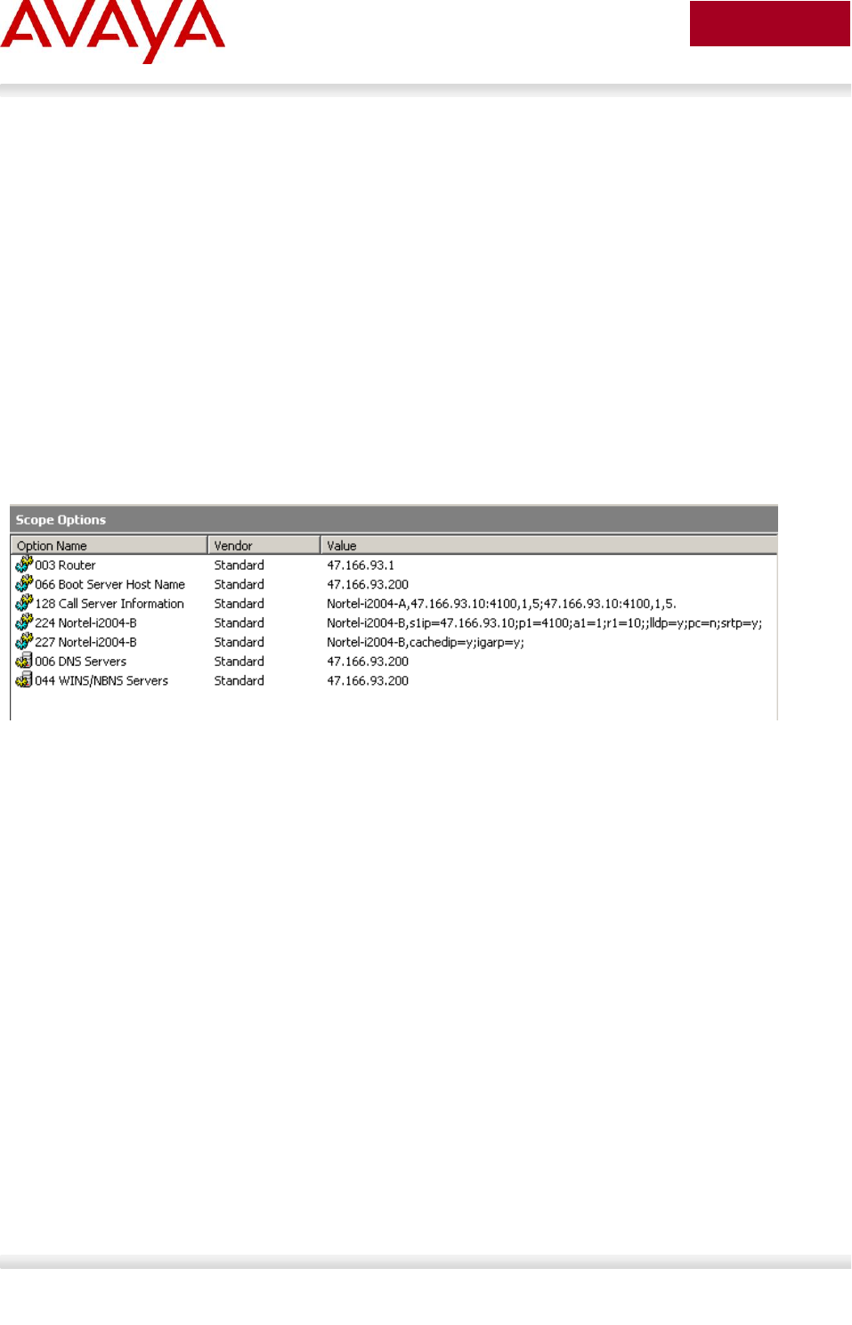
Avaya Inc. – External Distribution
140
avaya.com
Aug 2012
The priority rules are:
“Nortel-i2004-B” option’s priority is higher than the “Nortel-i2004-A” option’s.
Vendor specific DHCP options’ priorities are higher than the site specific DHCP options’.
The option with lower DHCP option number has higher priority than the option with higher DHCP
option number.
In the same DHCP option, the rear sub-string has higher priority than the front sub-string.
Setup of the DHCP server is very similar to what is done for the Default DHCP Options. The Predefined
Options still need to be defined initially and then enabled for the scope, using the choice of private options
as noted above.
The main change comes in defining the string for the Call Server information in the case of Expanded
DHCP Options, as the format is different. The Default DHCP Options uses the string Nortel-i2004-A at the
start of the DHCP option string; the Expanded DHCP Options uses the string Nortel-i2004-B instead. The
screenshot below shows the DHCP server with two private options (#224 and #227) configured for the
Expanded DHCP Options, in addition to the private earlier option (#128) for the Default DHCP Options.
The format of the Expanded DHCP option is obviously different to the earlier mode of operation; it is
easier to understand as it consists of a series of “parameter=value” combinations, each followed by a
semi colon.
Note that the string always begins with ‘Nortel-i2004-B’ where ‘B’ refers to the revision of the Nortel
DHCP/VLAN specification.
Nortel-i2004-B,param=value;param=value;param=value; …
Where
“Nortel-i2004-B” = the selected private option(s) for Expanded DHCP Options
begins with this string for 1100 series (C4I upwards) or 1200
series IP sets
“param” = a defined string representing one of the values that can be set
via Expanded DHCP Options
“value” = a valid value for the corresponding parameter
All parameters are separated by a semicolon (;). The string must end a semi colon (;).
As noted earlier, there can be multiple Nortel-i2004-B strings in order to pass the full range of parameters
possible, which in theory could exceed (at 310 bytes) the maximum length allowed for any one DHCP
option (255 bytes).
An example of the new Nortel-i2004-B Expanded DHCP Options is as follows.
Option 224

Avaya Inc. – External Distribution
141
avaya.com
Aug 2012
Nortel-i2004-B,s1=10.10.10.5;p1=4100;a1=1;r1=10;s2=10.10.10.10;p2=4100;a2=1;r2=10;
menulock=p;pc=n;
Option 227
Nortel-i2004-B,cachedip=n;igarp=y;srtp=n;
There is no change in the operation of the Voice VLAN Auto Discovery process as part of Extended
DHCP Options. That continues to use the same “VLAN-A” option type as with Default DHCP Options.
5.3 Auto Provisioning on Avaya IP Deskphones (1600-
Series, 9600-Series)
Multiple modes of configuration now exist for provisioning an Avaya IP Deskphone (1600-Series, 9600
Series). A hierarchy must be employed for configuration information. The hierarchy, as shown below, will
aid in resolution in the case of any conflict due to parameter settings from multiple sources.
LLDP
Manual Configuration
DHCP
HTTP/HTTPS script file
Avaya Media Server
Backup files
Settings the IP telephone receives from backup files or the media server overwrite any previous settings,
including manual settings. The only exception to this sequence is in the case of VLAN IDs. In the case of
VLAN IDs, LLDP settings of VLAN IDs are the absolute authority. Then the usual sequence applies
through HTTP/HTTPS.
5.3.1 LLDP
Release 1.2 9600 Series IP Deskphones and Release 1.1 1600 Series IP Deskphones support IEEE
802.1AB Link Layer Discovery Protocol (LLDP). For more information on LLDP, please refer to section
4.4. A 1600/9600 Series IP Deskphone initiates LLDP after receiving an LLDPDU message from an
appropriate system.
Once initiated, the 1600/9600 Series IP Deskphones send an LLDPDU every 30 seconds with the
following content.
Category
TLV Name (Type)
TLV Info String (Value)
Basic Mandatory
Chassis ID
IPv4 Address of IP Deskphone
Basic Mandatory
Port ID
MAC address of the IP Deskphone
Basic Mandatory
Time-To-Live
120 seconds.
Basic Optional
System Name
The Host Name sent to the DHCP
server in DHCP Option 12

Avaya Inc. – External Distribution
142
avaya.com
Aug 2012
Category
TLV Name (Type)
TLV Info String (Value)
Basic Optional
System Capabilities
Bit 2 (Bridge) is set if the IP
Deskphone has an internal Ethernet
switch.
Bit 5 (Telephone) will be set in the
System Capabilities. If Bit 5 is set in
the Enabled Capabilities than the IP
Deskphone is registered.
Basic Optional
Management Address
Mgmt IPv4 Address of IP
Deskphone. Interface number
subtype = 3 (system port). Interface
number = 1. OID = SNMP MIB-II
sysObjectID of the IP Deskphone.
IEEE 802.3
Organization Specific
MAC / PHY
Configuration/Status
Reports autonegotiation status and
speed of the uplink port.
TIA LLDP MED
LLDP-MED Capabilities
Media Endpoint Discovery – Class III
– IP Telephone
TIA LLDP MED
Extended Power-via-MDI
Power Value = 0 if the IP Deskphone
is not currently powered via PoE,
elese the maximum power usage of
the IP Deskphone plus all modules
and adjuncts powered by the IP
Deskphone in tenths of a watt.
TIA LLDP MED
Network Policy
Tagging Yes/No, VLAN ID for voice,
L2 Priority, DSCP Value
TIA LLDP MED
Inventory – Hardware Revision
MODEL – Full Model Name
TIA LLDP MED
Inventory – Firmware Revision
BOOTNAME
TIA LLDP MED
Inventory – Software Revision
APPNAME
TIA LLDP MED
Inventory – Serial Number
IP Deskphone serial number
TIA LLDP MED
Inventory – Manufacturer Name
Avaya
TIA LLDP MED
Inventory – Model Name
MODEL with the final Dxxx
characters removed.
Avaya Proprietary
PoE Conservation Level
Support
Provides Power Conservation
abilities/settings, Typical and
Maximum Power values
OUI = 00-40-0D (hex), Subtype = 1
Avaya Proprietary
Call Server IP Address
Call Server IP Address Subtype = 3
Avaya Proprietary
IP Phone Addresses
Phone IP Address, Phone Address
Mask, Gateway IP Address Subtype
= 4
Avaya Proprietary
CNA Server IP Address
CNA Server IP Address = in-use
value from CNASRVR Subtype = 5
Avaya Proprietary
File Server
File Server IP Address Subtype = 6
Avaya Proprietary
802.1Q Framing
802.1Q Framing = 1 if tagging or 2 if
not Subtype = 7
Basic Mandatory
End-of-LLDPDU
Not applicable

Avaya Inc. – External Distribution
143
avaya.com
Aug 2012
On receipt of a LLDPDU message, the Avaya IP Deskphone 1600/9600 Series IP Deskphone will act on
the TLV elements as described below.
System
Paramater Name
TLV Name
Impact
PHY2VLAN
IEEE 802.1 Port VLAN ID
System value changed to the Port VLAN
identifier in the TLV
L2QVLAN and
L2Q
IEEE 802.1 VLAN Name
The system value is changed to the TLV
VLAN Identifier. L2Q will be set to 1 (ON).
VLAN Name TLV is only effective if:
The telephone is not registered with
the Call Server.
Name begins with VOICE (case does
not matter).
The VLAN is not zero.
DHCP Client is activated.
The telephone is registered but is not
tagginglayer 2 frames with a non-
zero VLAN ID.
If VLAN Name causes the telephone to
change VLAN and the telephone already has
an IP Address the telephone will release the
IP Address and reset.
If the TLV VLAN ID matches the VLAN ID the
telephone is using, the VLAN ID is marked as
set by LLDP. Otherwise, if already registered,
the telephone waits until there are no active
calls, releases its IP Address, turns on
tagging with the TLV VLAN ID, sets L2Q to
"on," changes the default L2Q to "on," and
resets. If there is no valid IP Address, the
telephone immediately starts tagging
with the new VLAN ID without resetting.

Avaya Inc. – External Distribution
144
avaya.com
Aug 2012
System
Paramater Name
TLV Name
Impact
L2Q, L2QVLAN,
L2QAUD,
L2QSIG,
DSCPAUD,
DSCPSIG
MED Network Policy TLV
L2Q - set to “2” (off) If T (the Tagged Flag) is
set to 0; set to “1” (on) if T is set to 1.
L2QVLAN - set to the VLAN ID in the TLV.
L2QAUD and L2QSIG - set to the Layer 2
Priority value in the TLV.
DSCPAUD and DSCPSIG - set to the DSCP
value in the TLV.
A check is made as to whether a reset is
necessary to obtain a new IP address due to
a change in the values of the parameters
L2Q or L2QVLAN.
This TLV is ignored if:
the value of USE_DHCP is “0” and the
value
of IPADD is not “0.0.0.0”, or
the Application Type is not 1 (Voice), or
the Unknown Policy Flag (U) is set to 1.
MCIPADD
Proprietary Call Server
TLV
MCIPADD will be set to this value if it has not
already been set.
NOT USED WITH SIP IP DESKPHONE.
TLSSRVR and
HTTPSRVR
Proprietary File Server
TLV
TLSSRVR and HTTPSRVR will be set to this
value if neither of them have already been
set.
L2Q
Proprietary 802.1 Q
Framing
The default L2Q is set to the value of this
TLV. No change is made to the current L2
tagging, but the new default value is used on
the next reboot. If TLV = 1, L2Q set to "1"
(On). If TLV = 2, L2Q set to "2" (Off). If TLV =
3, L2Q set to "0" (Auto).
Proprietary – PoE
Conservation TLV
This proprietary TLV can initiate a power
conservation mode. The telephones that
support this will turn on/off the telephone
backlight and the backlight of an attached
Button Module in response to this TLV.
Exception: the 9670G display backlight
is put into low-power mode rather than being
turned off.

Avaya Inc. – External Distribution
145
avaya.com
Aug 2012
System
Paramater Name
TLV Name
Impact
Extended Power-via-MDI
Power conservation mode will be enabled if
the received binary Power Source value is
10, and power conservation mode will be
disabled if the received binary Power Source
value is not 10. Power conservation mode is
enabled even if the telephone is not powered
over Ethernet because the telephone sends
information about the power source that it is
using in a TIA LLDP MED Extended
Power-Via-MDI TLV; it is assumed that the
power management system intends to
conserve local power as well.
5.3.2 DHCP
Dynamic Host Configuration Protocol (DHCP) minimizes maintenance for a 1600/9600 Series IP
Deskphone network by removing the need to individually assign and maintain IP addresses and other
parameters for each IP Deskphone on the network.
The DHCP server provides the following information to the 1600/9600 Series IP Deskphones:
IP address of the 1600/9600 Series IP Telephone(s)
IP address of the Gatekeeper board on the Avaya Media Server
IP address of the HTTP or HTTPS server
The subnet mask
IP address of the router
DNS Server IP address
Administer the LAN so each IP Deskphone can access a DHCP server that contains the IPaddresses and
subnet mask.
Parameters requested by IP Phone (Option Code 55)
DHCP server
response: Option
Code
Subnet mak
1
Gateway (router) IP Address(es)
If using more than one address, the total list can contain up to 255 total
ASCII characters. You must separate IP addresses with commas with
no intervening spaces.
3
DNS Server(s) address list
6

Avaya Inc. – External Distribution
146
avaya.com
Aug 2012
If using more than one address, the total list can contain up to 127 total
ASCII characters. You must separate IP addresses with with no
intervening spaces. At least one address in Option 6 must be a valid,
non-zero, dotted decimal address.
Host name
Value is AVohhhhhh, where: o is “A” if the OID (first three octets) of
the MAC addressfor the telephone is 00-04-0D. “E” if the OID is 00-09-
6E, “L” if the OID is 00-60-1D,and “X” if the OID is anything else and
where hhhhhh are ASCII characters for the hexadecimal representation
of the last three octets of the MAC address for the IP Deskphone.
12
DNS domain name
15
Lease time — implementation varies according to DHCP server
51
Overload option (if desired). If this option is received in a message, the
IP Deskphone interprets the sname and file fields in accordance with
IETF RFC 2132.
52
Renewal time — implementation varies according to DHCP server
If not received or this value is greater than that for Option 51, the
default value of T1 (renewal timer) is used.
58
Rebinding interval — implementation varies according to DHCP server
If not received or this value is greater than that for Option 51, the
default value of T2 (rebinding timer) is used.
59
Vendor Class identifier
The default value is “ccp.avaya.com”.
60
Vendor-specific encapsulated or site options.
Refer to Appendix B-E for DHCP Configurable Paramaters.
242

Avaya Inc. – External Distribution
147
avaya.com
Aug 2012
5.3.3 Provisioning Server – Using HTTP or HTTPS
Avaya 1600/9600 IP Deskphones can retrieve application software, script file, and settings file from an
HTTP/HTTPS server. The addresses of the HTTP/HTTPS server must be provided to the IP Deskphone
in DHCP Option 242 or via LLDP or manually configured. Avaya 1600/9600 IP Deskphones will request a
“46xxsettings.txt” file and parse that file. Avaya maintains a current version of this file on
http://www.avaya.com/support with all available paramaters. An example file is shown in Appendix E.
5.3.4 SNMP
The 1600/9600 Series IP Deskphones are fully compatible with SNMPv2c and with Structure of
Management Information Version 2 (SMlv2). The Avaya custom MIB for the 1600/9600 Series IP
Deskphones is available in *.txt format on the Avay support web site at http://www.avaya.com/support.

Avaya Inc. – External Distribution
148
avaya.com
Aug 2012
5.4 Auto Detection and Auto Configuration (ADAC) of
Avaya IP Phones
ADAC can be used to automatically discover an IP Phone set either via MAC addresses or LLDP. In
addition, ADAC can be used with 802.1AB LLDP-MED to inform an IP Phone with the Voice VLAN ID and
QoS values
ADAC detection by MAC address works by checking the MAC address of the IP phone
against a MAC address range pre-configured on the switch. With the availability of
ADAC detection by LLDP, Avaya no longer recommends the use of ADAC detection by
MAC.
5.4.1 ADAC Operating Modes
ADAC can also be configured to automatically assign a port to a voice VLAN. The voice VLAN is an
independent VLAN leaning (IVL) port-based VLAN that can be applied to either tagged or untagged ports
with the following modes of operation:
Untagged Basic Mode
o No VLAN auto configuration will be applied
o ADAC Call Server or Uplink Port is not used
o The customer can create and configure the VLAN independently
o The IP Phone must be configured to send untagged frames
o QoS configuration is applied
o Auto-Configuration is applied only when a Avaya IP Phone is detected on a port
Untagged Advanced Mode
o Voice VLAN is created
o Call server port (if any)
Membership = add to Voice-VLAN
Tagging = UntaggedAll
PVID = Voice-VLAN
Up to 8 call server ports are supported starting with release 5.0 for the ERS
3500, release 5.4 for the ERS 4000 and 6.2 for the ERS 5000
o Uplink port (if any):
Membership = add to Voice-VLAN
Tagging = UntaggedAll
PVID = no change
Up to 8 uplink ports are supported starting with release 5.0 for the ERS 3500,
release 5.4 for the ERS 4000 and 6.2 for the ERS 5000
o Telephony port
Membership = remove from all other VLANs and add to Voice VLAN
Tagging = UntaggedAll
PVID = Voice-VLAN
o Port and PVID are assigned to Voice VLAN when phone is detected.

Avaya Inc. – External Distribution
149
avaya.com
Aug 2012
o The IP Phone must be configured to send untagged frames
o QoS configuration is applied
o Auto-Configuration is applied only when a Avaya IP Phone is detected on a port
o When ADAC is disabled, the port is placed back into the previously configured VLAN
Tagged Frames
o IP Phone are pre-configured to send tagged traffic
o Voice VLAN is configured
o Telephony port:
Membership = add to Voice-VLAN
Tagging = UntaggedPVIDOnly
PVID = unchanged or changed to DefaultVLAN (1) if equals Voice-VLAN
o Call Server port (if any):
Membership = add to Voice-VLAN
Tagging = UntaggedAll
PVID = Voice-VLAN
o Uplink port (if any):
Membership = add to Voice-VLAN
Tagging = TaggedAll
PVID = no change
Tagged mode
o Voice traffic is tagged from the IP phone must be configured with the VLAN ID of the
Voice VLAN
o QoS configuration is applied
o Auto-Configuration is applied only when a Avaya IP Phone is detected on a port

Avaya Inc. – External Distribution
150
avaya.com
Aug 2012
o Initial User Settings
When configuring ADAC, you must set the ADAC operation mode using one of the three operation modes
mentioned above according to if the IP Phones are configured to send tagged or untagged frames. If you
select either Untagged Advanced or Tagged mode, you must also supply the voice VLAN ID and at least
one of the following:
Call Server port, if it is connected directly to the switch
Uplink port, if used
o If you select Uplink port, this will enable tagging on the specified uplink port with a VLAN
ID of the voice VLAN.
5.4.2 QoS Settings
Overall, ADAC QoS configuration will be applied to:
traffic coming from the IP Phones
traffic coming from the Call Server port
traffic coming from the Uplink port
Auto QoS and 802.1AB MED Interopability
Starting with release 5.4 for the ERS 4000 and 6.2 for the ERS 5000, the LLDP-MED network
policy will be automatically be altered to match the Automatic QoS value if Automatic QoS is
enabled
Previously, when you enabled Automatic QoS, the LLDP-MED values where defined by the
network policy
ADAC Port Restrictions
The following applies to the Call Server, Uplink, and Telephony ports:
The Call Server port must not be:
part of a trunk (MLT, LAG)
a Monitor Port in port mirroring
a Telephony port
the Uplink port
The Uplink port must not be:
a Monitor Port in port mirroring
a Telephony port
the Call Server port
The Telephony port must not be:
part of a trunk (MLT, LAG)
a Monitor Port in port mirroring
an IGMP static router port
the Call Server port
the Uplink port

Avaya Inc. – External Distribution
151
avaya.com
Aug 2012
To support Auto Configuration on an Avaya IP Phone, an ADAC port must be
configured as untagPvidOnly with a default PVID belonging to the data VLAN even
though ADAC is configured with operation mode of Tagged. This will allow support for
an IP Phone with Auto Configuration and a data device on the same port. The data
device will be put in an untagged data VLAN and the IP Phone will be put into a different
tagged voice VLAN.
For ADAC MAC Detection to work, you must disable unregistered frames on the
ERS2500, ERS3500, ERS4000, and ERS5000 series.
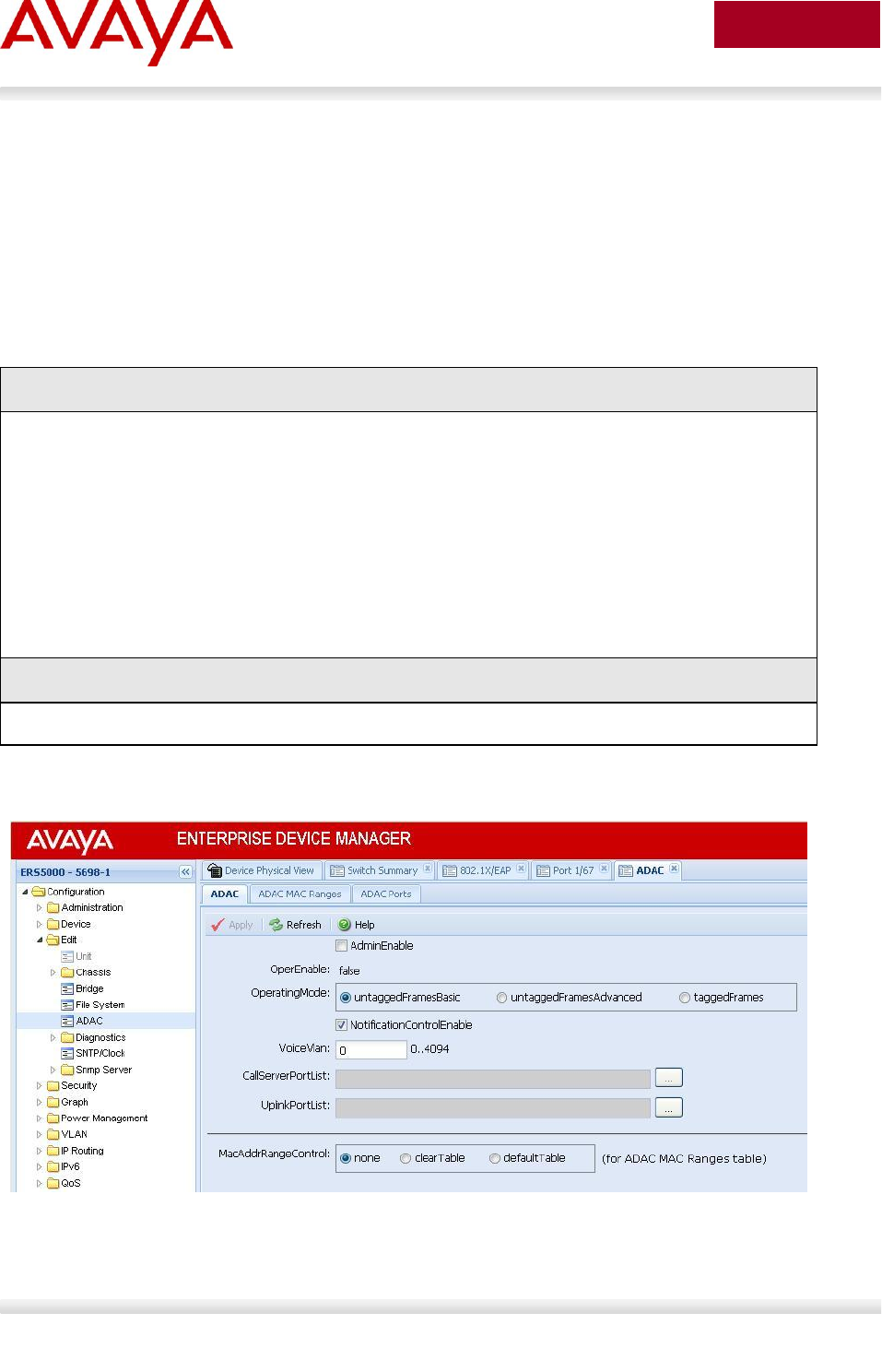
Avaya Inc. – External Distribution
152
avaya.com
Aug 2012
5.4.3 ADAC Configuration
ADAC can be configured by either using ACLI (CLI or ACLI on ERS8300), or using EDM (Enterprise
Device Manager).
5.4.3.1 ADAC Global Settings
ACLI
Via the privileged configuration terminal mode, the following command is used to enable ADAC:
Use the following command to view the various ADAC options:
ERS-Stackable(config)#adac ?
Parameters:
call-server-port Set call server port
enable Enable ADAC
op-mode Set ADAC operation mode
uplink-port Set uplink port
voice-vlan Set Voice-VLAN
Sub-Commands/Groups:
mac-range-table Add new supported MAC address range
Use the following command to disable ADAC:
ERS-Stackable(config)#no adac enable
EDM
Go to Configuration -> Edit -> ADAC

Avaya Inc. – External Distribution
153
avaya.com
Aug 2012
Where:
Item
Description
call-server-port
Sets Call Server port. Depending on the switch and software version
used, up to 8 call-server ports are supported.
enable
Enables ADAC on the switch.
op-mode
Sets the ADAC operation mode to one of the
following:
untagged-frames-basic: IP Phones send untagged frames and the
Voice VLAN is not created
untagged-frames-advanced: IP Phones send untagged frames and
the Voice VLAN is created
tagged-frames: IP Phones send tagged frames
uplink-port
Sets the Uplink port(s). Depending on the switch and software version
used, up to 8 uplinks are supported.
voice-vlan
Sets the Voice VLAN ID. The assigned VLAN ID must not previously
exist.
mac-range-table
Sets a new MAC addresses range used by ADAC to auto detect IP
Phone sets. NOTE: this option is only available for the ERS5500 series.
5.4.3.2 ADAC Interface settings
ACLI
ERS-Stackable: Use the following command to view the various ADAC options:
ERS-Stackable(config)#interface fastEthernet all
ERS-Stackable(config-if)#adac ?
Parameters:
enable Enable auto-detection on ports
port Port number(s) for which to change settings
tagged-frames-pvid Set the PVID to be configured for telephony ports in
Tagged Frames operating mode
tagged-frames-tagging Set the tagging to be configured for telephony ports
in Tagged Frames operating mode
Sub-Commands/Groups:
detection Enable detection mechanisms on ports
ERS-Stackable: Use the following command to view the various ADAC detection options:
ERS-Stackable(config)#interface fastEthernet all
ERS-Stackable(config-if)#adac detection ?
Parameters:
lldp Enable 802.1ab-based detection on ports
mac Enable MAC-based detection on ports
port Port number(s) for which to change settings
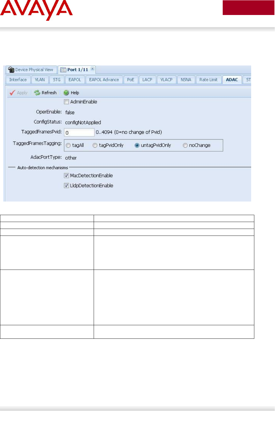
Avaya Inc. – External Distribution
154
avaya.com
Aug 2012
EDM
Go to Device Physical View -> right-click port(s) and select Edit -> ADAC
Where:
Item
Description
enable
Enables ADAC on the port or ports listed.
port <portlist>
Ports to which to apply the ADAC configuration.
tagged-frames-pvid
<1-4094> | no-change
Sets Tagged-Frames PVID on the port or ports
listed.
Use no-change to keep the current setting.
tagged-frames-tagging
tagAll | tagPvidOnly |
untagPvidOnly | no-change
Sets Tagged-Frames Tagging to
tagAll
tagPvidOnly
untagPvidOnly
Use no-change to keep the current setting.
ADAC Dectection variable
Specifies the ADAC detection method for either MAC or
LLDP. The default setting is MAC.

Avaya Inc. – External Distribution
155
avaya.com
Aug 2012
5.4.3.3 ADAC Support on Avaya Products
Model
Software
Release
ADAC
Detection
LLDP-
MED
Voice VLAN Tagging
MAC
LLDP
Untag
only
Tag only
Untag default
VLAN and tag
Voice VLAN
ERS2500
4.1
√1
√2
√
√
√
4.2
√1
√
√
√
√
√
ERS3500
5.0
√1
√
√
√
√
√
ERS4000
5.1
√1
√2
√
√
√
5.2
√1
√
√
√
√
√
ERS5500
5.0
√1
√
√
√
5.1
√1
√
√
√
√
√
ERS 5600
6.0
√1
√
√
√
√
√
1Requires filter unregistered frames to be disabled
Table 7: ADAC Support on Avaya Switches

Avaya Inc. – External Distribution
156
avaya.com
Aug 2012
5.5 Link Layer Discovery Protocol (IEEE 802.1AB)
IEEE 802.1AB LLDP is a Layer 2 neighbor discovery protocol. It defines a standard method for Ethernet
network devices such as switches, routers and IP Phones to advertise information about themselves to
other nodes on the network and store the information they discover.
LLDP was formally ratified as IEEE standard 802.1AB-2005 in May 2005.
LLDP defines
a set of common advertisement messages,
a protocol for transmitting the advertisements and
a method for storing the information contained in received advertisements.
The LLDP lets network management systems accurately discover and model physical network topologies.
As LLDP devices transmit and receive advertisements, the devices will store information they discover
about their neighbors. Details such as device configuration, device capabilities and device identification
can be advertised using this protocol.
LLDP can be used as a useful management tool – particularly for heterogeneous networks – by providing
accurate network mapping, inventory data and network troubleshooting information. LLDP enables
Ethernet network devices to inform each other about their configurations. A miss-configuration can be
easily detected and with suitable configuration management can be rectified.
Presently today, IP Phones do not have any SNMP or SONMP agent. Providing LLDP support in the
phone, allows the phones to exchange information between the phone and the L2/L3 data switch to which
it is attached. This allows the phone and the switch to exchange capabilities and for a network
administrator to have a more complete view of the network infrastructure. LLDP exchange between the IP
Phone and the data switch allows for the following:
VLAN assignment
QoS assignment
Duplex mismatch errors
Topology Recognition
Inventory Management
Basis for e911 location services – Nortel working group
Proprietary TLV – 802.1AB is flexible enough to define additional TLVs

Avaya Inc. – External Distribution
157
avaya.com
Aug 2012
5.5.1 Protocol Behavior
LLDPDU
Figure 10: IEEE 802.3 LLDP frame format
LLDPPDUs are transmitted with a multicast destination address specially identified for LLDPDU. The
LLDP-Multicast address is 01-80-C2-00-00-0E. An LLDPDU is identified based on the Ethertype
(Hexadecimal 88-CC) value carried in the MAC header. The neighboring devices do not acknowledge
LLDP information received from a device.
LLDP information is transmitted periodically and stored for a finite period. IEEE has defined a
recommended transmission rate of 30 seconds, but the transmission rate is adjustable. LLDP devices,
after receiving an LLDP message from a neighboring network device, will store the LLDP information in a
Management Information Base (MIB). LLDP information is stored in the MIB and is valid for a period of
time defined by the LLDP Time to Live (TTL).
An LLDP agent can operate in any of the following three modes:
1. Transmit-only mode: The agent can only transmit the information about the capabilities and the
current status of the local system.
2. Receive-only mode: The agent can only receive information about the capabilities and the current
status of the remote systems.
3. Transmit and receive mode: The agent can transmit the local system capabilities and status
information and receive remote system’s capabilities and status information.
The TIA extensions require a device claiming conformity with this protocol to implement both transmits
and receive mode.
6 octets
2 octets
1500 octets
MAC
address
88-CC
LLDPDU
FCS
01-80-C2-
00-00-0E
4 octets
TLV information string
DA
SA
LLDP
6 octets
7 bits
9 bits
0 ≤ n ≤ 511 octets
TLV information
string length
TLV information string
TLV type
= 127
TLV header
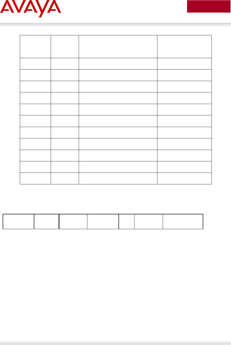
Avaya Inc. – External Distribution
158
avaya.com
Aug 2012
TLV Type
TLV
Sub Type
TLV Name
Usage in LLPDU
0
End of LLDPDU
Mandatory
1
Chassis ID
Mandatory
2
Port ID
Mandatory
3
Time to Live
Mandatory
4
Port Description
Mandatory
5
System Name
Optional
6
System Description
Optional
7
System Capabilities
Optional
8
Management Address
Optional
9-126
Reserved for future utilization
NA
127
Organizational specific TLVx
Optional
Table 8: TLV Type Values
5.5.2 Mandatory TLVs
Figure 11: LLDPDU Frame Format
The following mandatory TLVs shall be included at the beginning of each LLDPDU and shall be in the
following order
1. Chassis ID TLV - Identifies the 802 LAN device’s chassis,
2. Port ID TLV - Identifies the port from which the LLDPDU is transmitted,
3. Time-to-Live TLV - Indicates how long the received data is valid,
4. End-of-LLDPDU TLV - Indicates the end of TLVs in the LLDPDU and shall be the last TLV in the
LLDPDU
Optional TLVs as selected by network management may be inserted in any order.
M
M
M
Port ID
TLV
Time To
Live TLV
…
Optional
TLV
End of
LLDPDU TLV
Chassis ID
TLV
Optional
TLV
M

Avaya Inc. – External Distribution
159
avaya.com
Aug 2012
5.5.3 Optional TLVs
The optional TLVs provide various details about the LLDP agent advertising them. The LLDP agent can
advertise one or more of these TLVs in addition to the mandatory TLVs. The optional TLVs defined as
part of LLDP are grouped into two sets: Basic Management and Organizationally Specific extensions.
Currently the latter set includes three subsets: IEEE 802.1 extensions, IEEE 802.3 extensions, and TIA
Media Endpoint Discovery extensions.
5.5.4 Basic Management TLVs
This set includes the following five TLVs:
1. Port description TLV:
Provides a description of the port in an alpha-numeric format.
2. System name TLV:
Provides the system’s assigned name in an alpha-numeric format.
3. System description TLV:
Provides a description of the network entity in an alpha-numeric format.
4. System capabilities TLV:
Indicates the primary function(s) of the device such as Repeater, Bridge, WLAN AP, Router, or
Telephone.
5. Management address TLV:
Indicates the addresses of the local LLDP agent. Other remote managers can use this address to
obtain information related to the local device.
5.5.5 IEEE Organization Specific TLV
Figure 12: Organizationally Specific TLV Format
7 bits
9 bits
3 octets
1 octets
TLV information
string length
organizationally
unique identifier (OUI)
organizationally
defined subtype
organizationally defined
information string
TLV type
= 127
0 ≤ n ≤ 507
octets
TLV header
TLV information string
4 - 511 octets

Avaya Inc. – External Distribution
160
avaya.com
Aug 2012
This TLV category is provided to allow different organizations, such as IEEE 802.1, IEEE 802.3, IETF, as
well as individual software and equipment vendors, to define TLVs that advertise information to remote
entities attached to the same media.
OUI
TLV SubType
TLV Name
Usage in
LLDPDU
802.1
00-80-C2
1
Port VLAN ID
Mandatory
00-80-C2
2
Port & Protocol VLAN ID
Mandatory
00-80-C2
3
VLAN Name
Mandatory
00-80-C2
4
Protocol Identity
Mandatory
00-80-C2
0, 5-255
Reserved
-
802.3
00-12-0F
1
MAC/PHY configuration/status
Mandatory
00-12-0F
2
Power via MDI
Mandatory
00-12-0F
3
Link Aggregation
Mandatory
00-12-0F
4
Maximum Frame Size
Mandatory
00-12-0F
0, 5-255
Reserved
-
Table 9: Organizational TLV
IEEE 802.1 Organizational Specific TLV Set
This group includes the following four TLVs:
1. Port VLANID TLV:
The PVID that will be associated with an untagged or priority tagged data frame received on the
VLAN port.
2. PPVLAN ID TLV:
The PPVID that will be associated with an untagged or priority tagged data frame received on the
VLAN port.
3. VLAN name TLV:
The assigned name of any VLAN at the device. The number of VLAN name TLVs in an LLDPDU
corresponds to the number of VLANs enabled at the port.
4. Protocol identity TLV:
The set of protocols that is accessible at the device’s port.
IEEE 802.3 Organizational Specific TLV Set
This set includes the following four TLVs:
1. MAC/PHY configuration/status TLV:
Duplex and bit rate capability and the current duplex and bit rate settings of the sending device. It
also indicates whether the current settings are due to auto-negotiation or due to manual
configuration.

Avaya Inc. – External Distribution
161
avaya.com
Aug 2012
2. Power via media dependent interface (MDI) TLV:
The power support capabilities of the LAN device.
3. Link aggregation TLV:
Indicates whether the link (associated with the port on which the LLDPDU is transmitted) can be
aggregated
4. Maximum frame size TLV: The maximum frame size capability of the devices MAC and PHY
implementation.
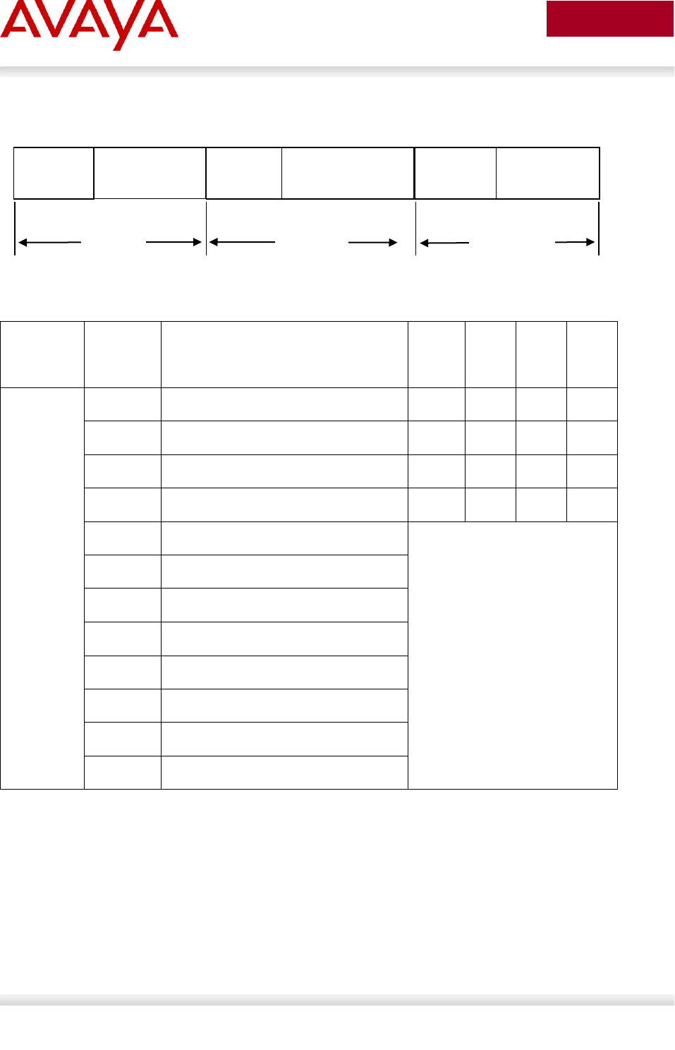
Avaya Inc. – External Distribution
162
avaya.com
Aug 2012
5.5.6 TIA LLDP-MED Extensions
Figure 13: LLDP-MED TLV Format
OUI
TLV
SubType
TLV Name
NCD
ED
I
ED
II
ED
III
00-12-BB
1
LLDP-MED Capabilities
M
M
M
M
2
Network Policy
C
O
M
M
3
Location Identification
C
O
4
Extended Power-via-MDI
C
C
C
C
5
Inventory – Hardware Revision
Optional TLV Set
Recommended when device
does not support SNMP
6
Inventory – Firmware Revision
7
Inventory – Software Revision
8
Inventory – Serial Number
9
Inventory – Manufacturer Name
10
Inventory – Model Name
11
Inventory – Asset ID
12-255
Reserved
Table 10: LLDP MED TLV
The Telecommunications Industry Association (TIA) has developed an extension to LLDP for VoIP
networks. VoIP-related extensions to LLDP, known as LLDP - Media Endpoint Discovery (LLDP-MED)
enable media devices to transmit and receive media related information.
In addition to expanding the LLDP TLVs, LLDP-MED requires certain optional LLDP TLVs to be
transmitted as mandatory information by media endpoints. Currently the TIA has defined the following
TLVs:
1. Capabilities Discovery TLV:
Indicates which MED capabilities are supported,
2. Network Policy Discovery TLV:
7 bits
9 bits
3
octets
1
octets
TLV
LLDP-Med
Capabilities
MED
Header
LLDP-MED
Capabilities
TIA OUI
00-12-BB
LLDP-MED
Capabilities
TLV
Type = 127
LLDP-MED
Capabilities
LLDP-MED
Device Type
2
octets
1
octets

Avaya Inc. – External Distribution
163
avaya.com
Aug 2012
Advertises the VLAN configuration and QoS attributes,
3. Location Identification Discovery TLV:
Advertises location information,
4. Extended Power-via MDI Discovery TLV:
Advertises power requirements,
5. Inventory Management Discovery TLVs:
Provide HW/firmware/SW revision, serial number, manufacturer/model name, and asset ID.
5.5.7 Vendor Specific 802.1AB (LLDP) TLVs
The Avaya Stackable Switches supports a number of Avaya vendor specific LLDP TLVs:
Enables the switch to provision the Phone via TLVs rather than DHCP/TFTP method
Improved provisioning capabilities by allowing the switch to configure: call-server, file-server, poe-
conservation, dot1q-framing
The switch can report on currently used parameters per port as well as listing the Phones in-use
IP parameters.
Integrates with Avaya Energy Saver, so that when Energy Saver is activated, the poe-
conservation parameter is dynamically changes to maximum to drive further power savings
PoE Convervation Level Request TLV
This TLV is used to advertise or request power conservation level to the end device.
This enables the switch to request the connected PD to go into a certain power conservation
level.
By default, the requested conservation value on this proprietary LLDP TLV is 0, which means no
power conservation.
This LLDP TLV is sent out only on PoE-capable Ethernet switching ports.
The higher the level the more power it will conserve.
If this power conservation level TLV is set and energy-saver is activated on the port, then the TLV
setting will be temporarily modified to the maximum power savings value.
Call Server TLV
This TLV is used to advertise up to 8 call servers IP Addresses.
This TLV allows the exchange of information from the switch to the connected IP Phone about the
IP addresses of the call server.
The Avaya IP Phone uses this addressing information after it receives the TLV from the switch to
reach the call server.
The information sent by the IP phone to the switch includes the IPv4 address used by the phone
to reach the call server.
Note: only IPv4 addressing is currently supported by this TLV.
File Server TLV
This TLV is used to advertise up to 4 file servers IP Addresses.
This TLV allows the exchange of information from the switch to the connected IP Phone about the
IP addresses of the file server.

Avaya Inc. – External Distribution
164
avaya.com
Aug 2012
The Avaya IP Phone uses this addressing information after it receives the TLV from the switch to
reach the file server.
The information sent by the IP phone to the switch includes the IPv4 address used by the phone
to reach the file server.
Note: only IPv4 addressing is currently supported by this TLV.
802.1Q Framing
This TLV is used to exchange information about Layer 2 priority tagging between the switch and
an IP phone.
The Avaya IP phone uses this addressing information after it receives the TLV from the switch.
This TLV works as an extension of the LLDP network policy TLV.
For this TLV to function, you must enable both: LLDP MED capabilities
TLV & LLDP MED network policy TLV.
IP Phone TLV
This TLV used by Avaya IP Phones to advertise their IP configuration information to the switch.
This can then be displayed by the switch as useful diagnostic information.
Note:only IPv4 addressing is currently supported by this TLV.
Avaya Inc. – External Distribution
165
avaya.com
Aug 2012
5.5.8 LLDP Support on Avaya Switches
Switch
802.1AB core
(mandatory
TLVs)
ORGANIZATIONAL
TLVs (802.1 and 802.3)
LLDP-MED
TLVs
ES 325/425
v 3.6
-
-
ES 470
v 3.7
-
-
ERS 2500
v 4.1
v 4.2
v 4.2
ERS 3500
v 5.0
v 5.0
v 5.0
ERS 4000
v 5.1
v 5.1
v 5.2
ERS 5500
v 5.01
v 5.012
v 5.01
ERS 5600
v 6.0
v 6.0
v 6.0
ERS 8300
v 2.3.1
v 3.01,3
v 3.04
1 Supported on a port configured with both a untagged data VLAN and tagged voice VLAN
2 The ERS55xx can send two LLDP VLAN Name packets, one for a Data VLAN and another for a Voice
VLAN. To do so, you must name the Data VLAN as “data” and the Voice VLAN as “voice”. The VLAN name is not
case-sensitive. The LLDP VLAN Name packet will contain the VLAN name and VLAN ID.
3 The ERS8300 only sends one LLDP VLAN Name packet. If a Voice VLAN is either not configured or not named
“voice”, the ERS8300 will send one LLDP VLAN Name packet providing you name a VLAN as “data”. The LLDP
VLAN Name packet will contain the name “data” and the VLAN ID. Otherwise, if you name a VLAN as “voice”, the
ERS8300 will only send one LLDP VLAN Name packet which will contain the name “voice” and the VLAN ID.
4 The ERS8300 supports LLDP-MED network policy as of release 4.2.3.0. For more details, please refer to the
4.2.3.0 release notes.
Table 11: LLDP Support on Avaya Switches

Avaya Inc. – External Distribution
166
avaya.com
Aug 2012
5.5.9 LLDP Configuration on Avaya IP Phone Sets and
Switches
The IP Phone sets can be set up for LLDP Vlan Name or LLDP-MED Network Policy but not both.
5.5.10 LLDP VLAN Name
Figure 14: Organizational TLV SubType 3 TLV Frame Format
7 bits
9 bits
3 octets
2 octets
1 octets
TLV information
string length
802.1 OUI
00-80-C2
VLAN ID
(VID)
VLAN name
length
VLAN
name
TLV type
= 127
802.1
subtype = 3
1 octets
1 - 32
octets
TLV header
TLV information string
8-39 octets
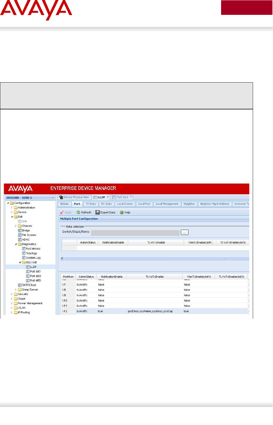
Avaya Inc. – External Distribution
167
avaya.com
Aug 2012
5.5.10.1 LLDP VLAN configuration on a Avaya Ethernet Switch
5.5.10.1.1 LLDP Interface level configuration
The following is an example of configuring LLDP on an Avaya Stackable Ethernet switch.
ERS-Stackable Step 1 – To enable LLDP on an Avaya Stackable Ethernet switch, please
enter the following commands assuming that ports 3 to 11 are used for both voice and
data using data VLAN 1000 and voice VLAN 800
ERS-Stackable(config)#interface fastEthernet 3-11
ERS-Stackable(config-if)#lldp tx-tlv local-mgmt-addr port-desc sys-cap sys-desc
sys-name
ERS-Stackable(config-if)#lldp status txAndRx config-notification
ERS-Stackable(config-if)#lldp tx-tlv port 12 dot1 port-vlan-id vlan-name
800,1000
EDM
Go to Configuration -> Edit -> Diagnostics -> 802.1AB -> LLDP -> Port
By default, the Avaya IP Phone set only uses the LLDP VLAN dot1 tx-tlv VLAN Name
where the LLDP VLAN Name packet contains the VLAN name and VLAN ID. The Avaya
IP Phone set requires the Voice VLAN to be named “voice” and the data VLAN to be
named “data”. The name is not case-sensitive. To set the LLDP tx-tlv dot1 VLAN name,
the Avaya switch by default will send the VLAN name assigned to the actual VLAN.
Hence, we rename both VLAN’s.
ERS-Stackable(config)#vlan name 1000 data
ERS-Stackable(config)#vlan name 800 voice

Avaya Inc. – External Distribution
168
avaya.com
Aug 2012
5.5.10.2 Verifying Operations
The following commands are used to verify the organizational TLV for both the local (switch) and remote
(IP Phone) devices assuming we have an IP Phone 2004 phone set connected to port 4.
5.5.10.2.1 Verify local TLV
Step 1 – Verify the local (switch) TLV by using the following command:
ERS-Stackable#show lldp port 4 local-sys-data dot1 dot3
Result:
-----------------------------------------------------------------------------
lldp local-sys-data chassis
-----------------------------------------------------------------------------
-----------------------------------------------------------------------------
ChassisId: MAC address 80:17:7d:26:68:00
SysName: ERS-Stackable
SysCap: rB / rB (Supported/Enabled)
SysDescr:
Ethernet Routing Switch ERS-Stackable HW:02 FW: 6.0.0.10 SW:v6.2.0.003
Dot1 protocols: STP,EAP,LLDP
-----------------------------------------------------------------------------
lldp local-sys-data port
-----------------------------------------------------------------------------
Port: 4
PVID: 1000 PPVID List: 800,1000
VLAN Name List: 800,1000 ProtocolId List: ALL
Dot3-MAC/PHY Auto-neg: supported/enabled OperMAUtype: 100BaseTXFD
PSE MDI power: supported/enabled Port class: PSE
PSE power pair: signal/not controllable Power class: 0
LinkAggr: not aggregatable/not aggregated AggrPortID: 0
MaxFrameSize: 9216
PMD auto-neg: 10Base(T, TFD), 100Base(TX, TXFD), (FdxS)Pause,
1000Base(TFD)
-----------------------------------------------------------------------------
Sys capability: O-Other; R-Repeater; B-Bridge; W-WLAN accesspoint; r-Router;
T-Telephone; D-DOCSIS cable device; S-Station only.
Core
TLV
802.1
802.3
Avaya Inc. – External Distribution
169
avaya.com
Aug 2012
5.5.10.2.2 Verify Remote TLV
Step 1 – Verify the remote (IP phone) TLV by using the following command:
ERS-Stackable(config)#show lldp port 4 neighbor dot1 dot3
Result:
----------------------------------------------------------------------------
lldp neighbor
----------------------------------------------------------------------------
Port: 4 Index: 157 Time: 4 days, 22:56:16
ChassisId: Network address ipV4 47.133.58.224
PortId: MAC address 00:0a:e4:09:72:e7
SysCap: TB / TB (Supported/Enabled)
PortDesc: Nortel IP Phone
SysDescr: Nortel IP Telephone 2004, Firmware:C604DB1
PVID: 0 PPVID Supported: not supported(0)
VLAN Name List: 800 PPVID Enabled: none
Dot3-MAC/PHY Auto-neg: supported/enabled OperMAUtype: 100BaseTXFD
PSE MDI power: not supported/disabled Port class: PD
PSE power pair: signal/not controllable Power class: 1
LinkAggr: not aggregatable/not aggregated AggrPortID: 0
MaxFrameSize: 1522
PMD auto-neg: (FdxS, FdxB)Pause, 1000Base(XFD, T)
----------------------------------------------------------------------------
Sys capability: O-Other; R-Repeater; B-Bridge; W-WLAN accesspoint; r-Router;
T-Telephone; D-DOCSIS cable device; S-Station only.
Core
TLC
802.1
802.3

Avaya Inc. – External Distribution
170
avaya.com
Aug 2012
5.5.10.3 LLDP VLAN configuration on the ERS8300
ERS8300 Step 1 – To enable LLDP on an ERS8300 switch, please enter the following
commands assuming that ports 31 is used for both voice and data using data VLAN 61
and voice VLAN 220
ERS8300:5# config ethernet 1/33 default-vlan-id 61
ERS8300:5# config ethernet 1/33 lldp tx-tlv local-mgmt-addr-tx enable
ERS8300:5# config ethernet 1/33 lldp tx-tlv sys-name enable
ERS8300:5# config ethernet 1/33 lldp tx-tlv sys-desc enable
ERS8300:5# config ethernet 1/33 lldp tx-tlv sys-cap enable
ERS8300:5# config ethernet 1/33 lldp tx-tlv port-desc enable
ERS8300:5# config ethernet 1/33 lldp tx-tlv dot1 vlan-name enable
By default, the Avaya IP Phone set only uses the LLDP VLAN dot1 tx-tlv VLAN Name
where the LLDP VLAN Name packet contains the VLAN name and VLAN ID. The Avaya
IP Phone set requires the Voice VLAN to be named “voice” and the data VLAN to be
named “data”. The name is not case-sensitive; however, on the ERS8300 you must
either use the name “voice” or “VOICE”. Also, the ERS8300 only sends one LLDP VLAN
Name packet. To set the LLDP tx-tlv dot1 VLAN name, the ERS8300 by default will
send the VLAN name assigned to the actual VLAN. Hence, we rename both VLAN’s.
ERS8300:5# config vlan 61 name data
ERS8300:5# config vlan 220 name voice
Avaya Inc. – External Distribution
171
avaya.com
Aug 2012
5.5.10.4 Verifying Operations
The following commands are used to verify the organizational TLV for both the local (switch) and remote
(IP Phone) devices assuming we have an IP Phone 2004 phone set connected to port 4.
5.5.10.4.1 Verify neighbor TLV
Step 1 – Verify the local (switch) core TLV by using the following command:
ERS8300B:5# show lldp neighbor 1/33
Result:
================================================================================
LLDP NEIGHBOR
================================================================================
PORT INDEX CHASSIS CHASSIS PORT PORT
NUM SUBTYPE ID SUBTYPE ID
PORT DESC SYS NAME SYS DESC
--------------------------------------------------------------------------------
1/33 22 NetworkAddr 10.103.59.201 MAC 00:13:65:fe:f1:cb
Nortel IP Phone Nortel IP Telephone 1120E, F
irmware:0624C22
================================================================================
lldp Remote-sys-data Sys Capabilitities
================================================================================
Repeater Bridge WLAN Router Telephone DOCICS Station Other
Access Pt Cable Only
(Supported/Enabled)
--------------------------------------------------------------------------------
No/No Yes/Yes No/No No/No Yes/Yes No/No No/No No/No
Step 2 – Verify the neighbor 802.1 TLV by using the following command:
ERS8300B:5# show lldp neighbor-dot1
Result:
================================================================================
LLDP NEIGHBOR (Dot1)
================================================================================
PORT INDEX CHASSIS CHASSIS PORT PORT
NUM SUBTYPE ID SUBTYPE ID
--------------------------------------------------------------------------------
PVID PPVID PPVID VlanName
Supported List Enabled List List
--------------------------------------------------------------------------------
1/33 11 NetworkAddr 10.103.59.200 MAC 00:0a:e4:09:72:e7
0 0 0 220
Core
TLV

Avaya Inc. – External Distribution
172
avaya.com
Aug 2012
Step 3– Verify the neighor 802.3 TLV by using the following command:
ERS8300B:5# show lldp neighbor-dot3
Result:
================================================================================
LLDP NEIGHBOR (Dot3)
================================================================================
--------------------------------------------------------------------------------
PORT INDEX CHASSIS CHASSIS PORT PORT
NUM SUBTYPE ID SUBTYPE ID
--------------------------------------------------------------------------------
1/33 11 NetworkAddr 10.103.59.200 MAC 00:0a:e4:09:72:e7
Dot3-MAC/PHY Autoneg : Supported/Enabled
OperMAUtype : 100BaseTXFD
PMD auto-neg : 1000-half
PSE MDI power :
Port Class :
PSE pair control : Signal
Power Class : Class 1
Link Aggregation : Supported
Link Aggregation Port ID : 0
MaxFrameSize : 1522

Avaya Inc. – External Distribution
173
avaya.com
Aug 2012
5.5.11 LLDP-MED (Media Endpoint Devices) Network Policy
Figure 15: LLDP-MED Network Policy TLV SubType 2 Frame Format
5.5.11.1 LLDP-MED configuration on an Avaya Stackable Ethernet
Routing Switch
Depending on the switch model and software version used, ADAC may have to be enabled on the switch
to allow LLDP-MED. As of software release 5.1.4 for the ERS5500, software 6.1 for the ERS5500 or
ERS5600, or software release 5.4 for the ERS 4000, ADAC is no longer required in order to enable
LLDP-MED network policy.
For the ERS 2500 or older releases for the ERS 4000 or ERS 5000, in order to support LLDP-MED
Network Policy TLV, ADAC must be used in addition to enabling, at minimum, LLDP-MED Capabilities
TLV and LLDP-MED Network Policy TLV.
5.5.11.1.1 ADAC Configuration for LLDP-MED
Assuming the Ethernet Routing Switch is configured as a Layer 2 switch with a trunked uplink port 1 and
access ports 3 to 11 for IP phones where we wish to tag the ADAC voice VLAN and untag the data
VLAN, enter the following.
Please note that by default, ADAC detection by MAC and LLDP is enabled. The
configuration below allows only for ADAC detection by LLDP by disabling ADAC
detection by MAC using interface command no adac detection port <port list> mac.
Step 1 – Enable ADAC
ERS-Stackable(config)#adac voice-vlan 280
ERS-Stackable(config)#adac uplink-port 1
ERS-Stackable(config)#adac op-mode tagged-frames
ERS-Stackable(config)#adac enable
ERS-Stackable(config)#interface FastEthernet ALL
ERS-Stackable(config-if)#no adac detection port 3-11 mac
ERS-Stackable(config-if)#adac tagged-frames-tagging untag-pvid-only
ERS-Stackable(config-if)#adac port 3-11 enable
ERS-Stackable(config-if)#exit
7 bits
9 bits
3
octets
1
octets
1
octets
3 bits
12
bits
TLV
Network Policy
4 octets
MED
Header
Network Policy
String Length = 8
MED OUI
00-12-BB
Application
Type
U
L2
Priority
TLV
Type = 127
Network Policy
Subtype = 2
T
X
DSCP
Value
VLAN
ID
3 bits
6 bits

Avaya Inc. – External Distribution
174
avaya.com
Aug 2012
5.5.11.1.2 LLDP-MED Configuration
After ADAC has been configured, enable LLDP-MED by entering the following commands.
Step 1 – Enable ADAC and also set PoE priority level to high
ERS-Stackable(config)#interface fastEthernet 3-11
ERS-Stackable(config-if)#poe poe-priority high
ERS-Stackable(config-if)#lldp status txAndRx
ERS-Stackable(config-if)#lldp tx-tlv local-mgmt-addr port-desc sys-cap sys-
desc sys-name
ERS-Stackable(config-if)#lldp tx-tlv med extendedPSE med-capabilities network-
policy
ERS-Stackable(config-if)#exit
EDM
Go to Configuration -> Edit -> Diagnostics -> 802.1AB -> Port
We will also add LLDP-MED extendedPSE so that we can compare PoE settings
between the IP Phone set and the switch.
Avaya Inc. – External Distribution
175
avaya.com
Aug 2012
5.5.11.2 Verifying Operations
Assuming an IP Phone 2004 IP Phone set is connected to port 4.
5.5.11.2.1 Verify LLDP-MED
Step 1 – Verify LLDP-MED operation by using the following command:
ERS-Stackable# show lldp port 4 neighbor med
Result:
----------------------------------------------------------------------------
lldp neighbor
----------------------------------------------------------------------------
Port: 4 Index: 4 Time: 0 days, 00:01:43
ChassisId: Network address ipV4 47.133.58.220
PortId: MAC address 00:0a:e4:09:72:e7
SysCap: TB / TB (Supported/Enabled)
PortDesc: Nortel IP Phone
SysDescr: Nortel IP Telephone 2004, Firmware:C604DB1
MED-Capabilities: CNSD / CNDI (Supported/Current)
MED-Device type: Endpoint Class 3
MED-Application Type: Voice VLAN ID: 280
L2 Priority: 6 DSCP Value: 46 Tagged Vlan, Policy defined
Med-Power Type: PD Device Power Source: Unknown
Power Priority: High Power Value: 5.4 Watt
----------------------------------------------------------------------------
Sys capability: O-Other; R-Repeater; B-Bridge; W-WLAN accesspoint; r-Router;
T-Telephone; D-DOCSIS cable device; S-Station only.
Med Capabilities-C: N-Network Policy; L-Location Identification; I-Inventory;
S-Extended Power via MDI - PSE; D-Extended Power via MDI - PD.
Core
TLC
MED

Avaya Inc. – External Distribution
176
avaya.com
Aug 2012
5.5.11.2.2 Verify ADAC Detection
Step 1 – Verify ADAC detection by using the following command assuming IP Phones are
connected to ports 4 and 5:
ERS-Stackable#show adac interface 3-11
Result:
Auto Oper Auto
Port Type Detection State Configuration T-F PVID T-F Tagging
---- ---- --------- -------- ------------- --------- ---------------
3 T Enabled Enabled Not Applied No Change Untag PVID Only
4 T Enabled Enabled Applied No Change Untag PVID Only
5 T Enabled Enabled Applied No Change Untag PVID Only
6 T Enabled Enabled Not Applied No Change Untag PVID Only
7 T Enabled Enabled Not Applied No Change Untag PVID Only
8 T Enabled Enabled Not Applied No Change Untag PVID Only
9 T Enabled Enabled Not Applied No Change Untag PVID Only
10 T Enabled Enabled Not Applied No Change Untag PVID Only
11 T Enabled Enabled Not Applied No Change Untag PVID Only
Step 2 – Verify ADAC detection mechanism enabled by issuing the following command:
ERS-Stackable#show adac detection interface 3-11
Result:
MAC LLDP
Port Detection Detection
---- --------- ---------
3 Disabled Enabled
4 Disabled Enabled
5 Disabled Enabled
6 Disabled Enabled
7 Disabled Enabled
8 Disabled Enabled
9 Disabled Enabled
10 Disabled Enabled
11 Disabled Enabled

Avaya Inc. – External Distribution
177
avaya.com
Aug 2012
5.5.11.3 LLDP-MED configuration on Stackable Ethernet Routing
Switch without ADAC
In software release 5.0.1 or higher for the ERS 3500, software release 5.1.4 or higher for the ERS5500,
software release 6.3 for the ERS5500 or ERS5600, or software release 5.4 for the ERS 4000, you can
use LLDP-MED network policy to configure the voice VLAN, Layer 3 QoS level (DSCP value) and the
Layer 2 QoS level (802.1p value). The DSCP value is entered in decimal with a value from 0 to 63 while
the p-bit value is also entered in decimal with a value from 0 to 7.
The command syntax to enable the MED network policy is as follows at an interface level:
ERS-Stackable(config-if)#lldp med-network-policies voice dscp <0-63> priority <0-7>
tagging <tagged|untagged> vlan-id <1-4094>
The default MED policy values are: DSCP = 0, Priority = 0, Tagging Mode = untagged, VLAN-ID = 1.
As of software release 5.4 for the ERS 4000 and 6.2 for the ERS 5000, Auto QoS and
LLDP-MED interoperates with each other. Auo QoS, when enabled, will now alter the
LLDP-MED Network Policy to match the Auto QoS values. Previously, the LLDP MED
values where determined by the Network Policy - there was no interaction between Auto
QoS and LLDP-MED.
Assuming the Stackable Ethernet Routing switch switch is configured as a Layer 2 switch with access
ports 3 to 11 for IP phones, enter the following assuming you are using VLAN 805 for the voice VLAN and
you wish to use a DSCP value of 46 and a p-bit value of 6.
ERS-Stackable Step 1 – Add LLDP MED Network Policy
ERS-Stackable(config)#interface fastEthernet 3-11
ERS-Stackable(config-if)#lldp med-network-policies voice dscp 46 priority 6
tagging tagged vlan-id 805
ERS-Stackable(config-if)#exit
LLDP Tx-TLVs – Older Software Releases
Depending on the software release used, it may be nessessary to enable LLDP TLVs. This does not
apply to the ERS 4000 as of release 5.5, ERS 3500 as of release 5.0.1, and ERS 5000 as of release 6.3
from a factory default setting, but, to verify if the TLVs are enabled or not, please enter the ACLI
commands show lldp port 3-11 & show lldp tx-tlv.
ERS-Stackable Step 1 – Enable LLDP TLVs
ERS-Stackable(config)#interface fastEthernet 3-11
ERS-Stackable(config-if)#lldp tx-tlv local-mgmt-addr port-desc sys-cap sys-desc
sys-name
ERS-Stackable(config-if)#lldp status txandRx config-notification
ERS-Stackable(config-if)#lldp tx-tlv med extendedPSE inventory location med-
capabilities network-policy
ERS-Stackable(config-if)#exit
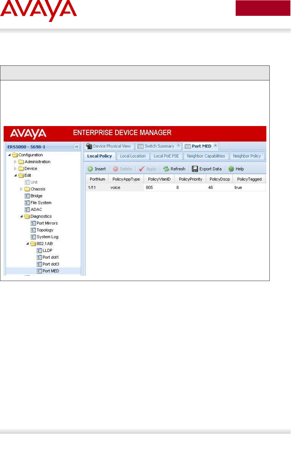
Avaya Inc. – External Distribution
178
avaya.com
Aug 2012
Step 1 – Using EDM
EDM
Go to Configuration -> Edit -> Diagnostics -> 802.1AB -> LLDP -> Port
and then
Go to Configuration -> Edit -> Diagnostics -> 802.1AB -> Port MED -> Insert
Avaya Inc. – External Distribution
179
avaya.com
Aug 2012
5.5.11.4 LLDP Vendor Specific Avaya Configuration
ERS-Stackable– Integrated Power Conservation TLV
ERS-Stackable(config)#interface fastEthernet 1
ERS-Stackable(config-if)#lldp vendor-specific avaya poe-conservation-request-
level 7
ERS-Stackable(config-if)#exit
ERS-Stackable– Call Server TLV
ERS-Stackable(config)#lldp avaya call-server 172.16.1.101 2 172.16.1.102
ERS-Stackable– File Server TLV
ERS-Stackable(config)#lldp avaya file-server 172.16.1.103 2 172.16.1.104
ERS-Stackable– 802.1Q Framing TLV
ERS-Stackable(config)#interface fastEthernet 1
ERS-Stackable(config-if)#lldp vendor-specific avaya dot1q-framing <tagged |
untagged | auto>
ERS-Stackable(config-if)#exit

Avaya Inc. – External Distribution
180
avaya.com
Aug 2012
5.5.11.5 Verify Operations
Assuming an IP Phone 1230 IP Phone set is connected to port 5.
5.5.11.5.1 Verify LLDP-MED
Step 1 – Verify LLDP neighbor details by using the following command:
ERS-Stackable#show lldp port 5 neighbor detail
Result:
-------------------------------------------------------------------------------
lldp neighbor
-------------------------------------------------------------------------------
Port: 5 Index: 4 Time: 3 days, 19:18:15
ChassisId: Network address IPv4 10.5.85.10
PortId: MAC address 00:24:00:0d:8d:aa
SysCap: TB / TB (Supported/Enabled)
PortDesc: Nortel IP Phone
SysDescr: Nortel IP Telephone 1230, Firmware:062AC6R
PVID: 0 PPVID Supported: not supported(0)
VLAN Name List: 805 PPVID Enabled: none
Dot3-MAC/PHY Auto-neg: supported/enabled OperMAUtype: 100BaseTXFD
PSE MDI power: not supported/disabled Port class: PD
PSE power pair: signal/not controllable Power class: 2
LinkAggr: not aggregatable/not aggregated AggrPortID: 0
MaxFrameSize: 1522
PMD auto-neg: 10Base(T, TFD), 100Base(TX, TXFD)
MED-Capabilities: CNLDI / CNDI (Supported/Current)
MED-Device type: Endpoint Class 3
MED-Application Type: Voice VLAN ID: 805
L2 Priority: 6 DSCP Value: 46 Tagged Vlan, Policy defined
Med-Power Type: PD Device Power Source: Unknown
Power Priority: High Power Value: 6.0 Watt
HWRev: FWRev: 062AC6R
SWRev: SerialNumber:
ManufName: Nortel-05 ModelName: IP Phone 1230
AssetID:
-------------------------------------------------------------------------------
Sys capability: O-Other; R-Repeater; B-Bridge; W-WLAN accesspoint; r-Router;
T-Telephone; D-DOCSIS cable device; S-Station only.
Total neighbors: 1
Med Capabilities-C: N-Network Policy; L-Location Identification; I-Inventory;
S-Extended Power via MDI - PSE; D-Extended Power via MDI - PD.
Avaya Inc. – External Distribution
181
avaya.com
Aug 2012
Step 2 – Verify LLDP-MED operations by using the following command:
ERS-Stackable#show lldp port 5 neighbor med network-policy
Result:
-------------------------------------------------------------------------------
lldp neighbor
-------------------------------------------------------------------------------
Port: 5 Index: 4 Time: 3 days, 19:18:15
ChassisId: Network address IPv4 10.5.85.10
PortId: MAC address 00:24:00:0d:8d:aa
SysCap: TB / TB (Supported/Enabled)
PortDesc: Nortel IP Phone
SysDescr: Nortel IP Telephone 1230, Firmware:062AC6R
MED-Application Type: Voice VLAN ID: 805
L2 Priority: 6 DSCP Value: 46 Tagged Vlan, Policy defined
-------------------------------------------------------------------------------
Sys capability: O-Other; R-Repeater; B-Bridge; W-WLAN accesspoint; r-Router;
T-Telephone; D-DOCSIS cable device; S-Station only.
Total neighbors: 1
5.5.11.5.2 Verify LLDP-MED Policy Configuration
Step 1 – Verify LLDP neighbor details by using the following command:
ERS-Stackable# show lldp med-network-policies voice
Result:
----------------------------------------------------------------
lldp voice network-policies
----------------------------------------------------------------
----------------------------------------------------------------
Port Voice Tagging DSCP Priority
VlanID
----------------------------------------------------------------
3 805 tagged 46 6
4 805 tagged 46 6
5 805 tagged 46 6

Avaya Inc. – External Distribution
182
avaya.com
Aug 2012
6 805 tagged 46 6
7 805 tagged 46 6
8 805 tagged 46 6
9 805 tagged 46 6
10 805 tagged 46 6
11 805 tagged 46 6
----------------------------------------------------------------
5.5.11.5.3 Verify Vendor Specific Avaya TLVs
ERS-Stackable– Integrated Power Conservation TLV
ERS-Stackable#show lldp neighbor vendor-specific avaya poe-conservation
Results:
-------------------------------------------------------------------------------
Neighbors LLDP info - Avaya TLVs
-------------------------------------------------------------------------------
-------------------------------------------------------------------------------
Port: 1/3
Phone PoE Conservation Levels:
Crt. Conservation Level: 1
Typical Power: 4.9 Watts
Max Power: 5.6 Watts
Supported Conservation Levels:
Level 1: 4.5 Watts
ERS-Stackable– Call Server TLV
ERS-Stackable)#show lldp vendor-specific avaya call-server
ERS-Stackable)#show lldp neighbor vendor-specific avaya call-server
Results:
-------------------------------------------------------------------------------
LLDP Avaya Call Servers IP addresses
-------------------------------------------------------------------------------
-------------------------------------------------------------------------------
Avaya Configured Call Server 1: 172.16.2.101
Avaya Configured Call Server 2: 172.16.2.102
-------------------------------------------------------------------------------
Avaya Inc. – External Distribution
183
avaya.com
Aug 2012
ERS-Stackable– File Server TLV
ERS-Stackable#show lldp vendor-specific avaya file-server
ERS-Stackable#show lldp neighbor vendor-specific avaya file-server
Results
-------------------------------------------------------------------------------
LLDP Avaya File Servers IP addresses
-------------------------------------------------------------------------------
-------------------------------------------------------------------------------
Avaya Configured File Server 1: 172.16.2.103
Avaya Configured File Server 1: 172.16.2.10
-------------------------------------------------------------------------------
ERS-Stackable– 802.1Q Framing TLV
ERS-Stackable#show lldp vendor-specific avaya dot1q-framing
ERS-Stackable#show lldp port 1/3 vendor-specific avaya dot1q-framing
Results
-------------------------------------------------------------------------------
LLDP vendor-specific Avaya 802.1Q Framing
-------------------------------------------------------------------------------
-------------------------------------------------------------------------------
Unit/ Framing
Port Tagging Mode
-------------------------------------------------------------------------------
1/3 tagged
ERS-Stackable– IP Phone TLV
ERS-Stackable#show lldp vendor-specific avaya phone-ip
ERS-Stackable#show lldp port 1/3 vendor-specific avaya phone-ip
Results
-------------------------------------------------------------------------------
Neighbors LLDP info - Avaya TLVs
-------------------------------------------------------------------------------
-------------------------------------------------------------------------------
Port: 4/15

Avaya Inc. – External Distribution
184
avaya.com
Aug 2012
Avaya Phone IP:
Address: 172.16.2.11
Netmask: 255.255.255.0
Gateway: 172.16.2.1
5.5.11.6 LLDP-MED configuration on the ERS8300
In order to support LLDP-MED Network Policy TLV, ADAC must be enabled on an interface level in
addition to enabling at minimum LLDP-MED Capabilities TLV and LLDP-MED Network Policy TLV.
Assuming the ERS8300 is configured as a Layer 2 switch with access ports 1/1 to 1/5 for IP phones,
enter the following:
5.5.11.6.1 Enable ADAC at interface level
ERS8300-1 Step 1 – Enable ADAC on port members 1/1 to 1/5
CLI
ERS8300-2:5# config ethernet 1/1-1/5 adac enable
ACLI
ERS8310-1:5(config)#interface fastEthernet 1/1-1/5
ERS8310-1:5(config-if)#adac port enable
ERS8310-1:5(config-if)#exit

Avaya Inc. – External Distribution
185
avaya.com
Aug 2012
5.5.11.6.2 Enable LLDP-MED
ERS8300-1 Step 1 – Enable LLDP VLAN name on port 1/1 to 1/5
CLI
ERS8300-2:5# config ethernet 1/1-1/5 lldp tx-tlv local-mgmt-addr-tx enable
ERS8300-2:5# config ethernet 1/1-1/5 lldp tx-tlv sys-name enable
ERS8300-2:5# config ethernet 1/1-1/5 lldp tx-tlv sys-desc enable
ERS8300-2:5# config ethernet 1/1-1/5 lldp tx-tlv sys-cap enable
ERS8300-2:5# config ethernet 1/1-1/5 lldp tx-tlv port-desc enable
ERS8300-2:5# config ethernet 1/1-1/5 lldp tx-tlv med network-policy enable
ERS8300-2:5# config ethernet 1/1-1/5 lldp tx-tlv med extendedPSE enable
ERS8300-2:5# config ethernet 1/1-1/5 lldp tx-tlv med capabilities enable
ACLI
ERS8310-1:5(config)#interface fastEthernet 1/1-1/5
ERS8310-1:5(config-if)#lldp tx-tlv local-mgmt-addr
ERS8310-1:5(config-if)#lldp tx-tlv sys-name sys-desc sys-cap
ERS8310-1:5(config-if)#lldp tx-tlv port-desc
ERS8310-1:5(config-if)#lldp status txAndRx
ERS8310-1:5(config-if)#lldp tx-tlv med capabilities extendedPSE
ERS8310-1:5(config-if)#lldp tx-tlv med network-policy
ERS8310-1:5(config-if)#exit
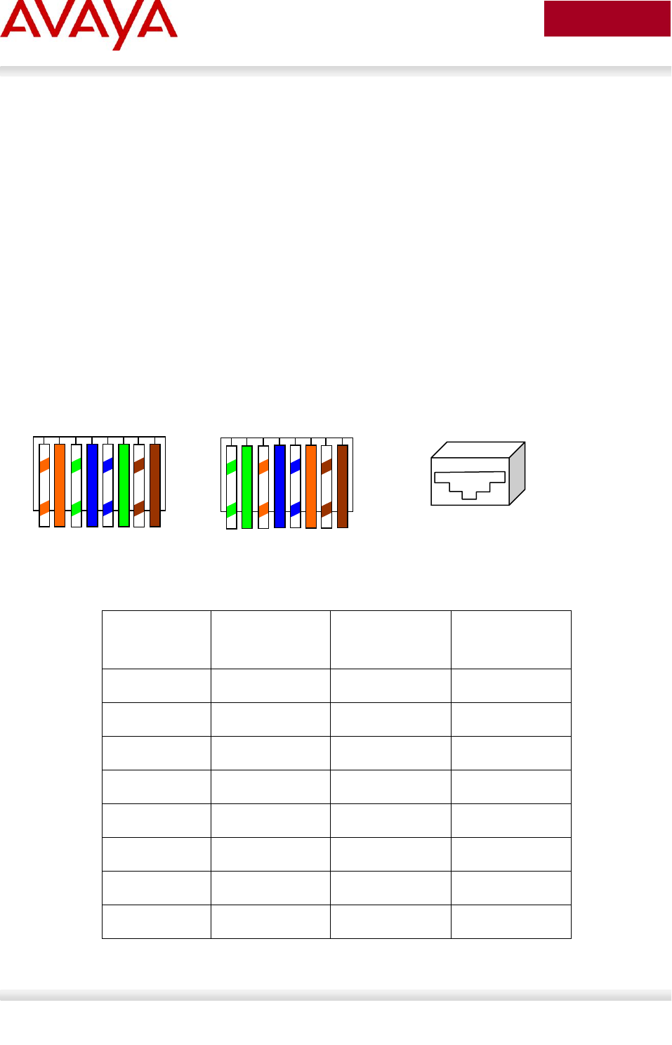
Avaya Inc. – External Distribution
186
avaya.com
Aug 2012
6. 802.3af and 802.3at (PoE+) Power over
Ethernet
The intention of the 802.3af standard is to provide a 10BaseT, 100BaseT, or1000BaseT device with a
single interface for the data it requires and the power to process the data. Power is supplied by a Power
Sourcing Device (PSE) for one or more Powered Devices (PD). The PSE main function is to only supply
power for a PD after it has successfully detected a PD on a link by probing. The PSE can also
successfully detect a PD, but then opt to not supply power to the detected PD. The PSE shall only supply
power on the same pair as those used for detection.
The cable requirements are defined in ISO/IEC 11801-2000 and EIA/TIA 568A/B (T-568A or B, with most
using the A standard) which allows for up to 100 meters of cable.
Power Sourcing Devices (PSE) can deliver power on the data pairs (1+2, 3+6), spare pairs (4+5, 7+8), or
either, but only on the pair that the Powered Device (PD) is detected on. Power is not to be supplied to
non-powered devices and other PSE’s.
Figure 16: PD and PSE 8-pin Modular Jack Pin’s
Conductor
Alternative A
(MDI-X)
Alternative A
(MDI)
Alternative B
(All)
1
Negative VPort
Positive VPort
2
Negative VPort
Positive VPort
3
Positive VPort
Negative VPort
4
Positive VPort
5
Positive VPort
6
Positive VPort
Negative VPort
7
Negative VPort
8
Negative VPort
Table 12: PSE Pinout Alternative
1 2 3 4 5 6 7 8
1 2 3 4 5 6 7 8
T-568B
T-568A
O/ 0 G/ B B/ G Br/ Br
G/ G O/ B B/ O Br/ Br
1 2 3 4 5 6 7 8
Avaya Inc. – External Distribution
187
avaya.com
Aug 2012
In regards to the PD, it must fall into the following characteristics:
19k to 26.5k ohm DC resistance
<100nF of capacitance and
a voltage offset of at least 2VDC in the signature characteristics
a current of less than 12uA in the signature characteristics
Anything outside of the characteristics listed above will be considered a non-PD device and the PSE will
not supply power. Each port from a PSE should be capable of delivering up to 15.4W of power. 802.3af
also adds a class feature that allows the PSE to limit the power based on the class of the PD detected.
Table 13 shown below lists the 802.3af power classes.
Class
Usage
Range of MAXIMUM power used by the PD
0
Default
0.44 to 12.95 Watts
1
Optional
0.44 to 3.84 Watts
2
Optional
3.84 to 6.49 Watts
3
Optional
6.49 to 12.95 Watts
4
Not Allowed
Reserved for Future Use
Table 13: 802.3af PD Power Classification
6.1 IP Deskphone Power Requirements
Table 14 displays the average power consumed for each Avaya IP Phone set.
Model
Product Code
PoE
Class
Typical
use Power
(Watts)
Minimum Software
2007
All
3
9.6
1110
All
2
2.8
1120E
NTYS03xA – NTYS03xCE6
3
7.0
1120E
NTYS03xDE6
3
4.6
UNISTIm 3.1 / SIP 2.1
1120E
NTYS03xEE6, NTYS03xFE6
2
4.2
UNISTim 3.4 / SIP 2.2
1140E
NTYS05xA – NTYS05xCE6
3
7.3
1140E
NTYS05xCE6 Rel 50 & higher
3
4.8
UNISTIm 3.1 / SIP 2.1
Avaya Inc. – External Distribution
188
avaya.com
Aug 2012
1140E
NTYS05xEE6, NTYS05xFE6
2
4.3
UNISTim 3.4 / SIP 2.2
1150E
NTYS06xxE6
3
7.0
1165E
NTYS07xxE6
2
3.8
1210
All
2
3.2
1220
All
2
3.2
1230
All
2
3.2
1603-I
All
2
4.32
1603SW-I
All
2
4.32
1608-I
All
2
4.66
1616-I
All
2
3.17
1616 w/BM32
All
2
4.37
9608
All
1
2.0
9611G
All
1
3.1
9620L
All
1
2.2
9620C
All
2
4.6
9621G
All
2
3.5
9630G
All
2
4.8
9640
All
2
4.5
9640G
All
2
4.8
9641G
All
2
3.4
9650
All
2
4.6
9650C
All
2
4.5
9670G
All
2
6.2
Table 14: IP Deskphone Power Requirements
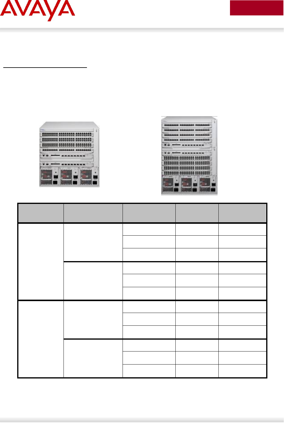
Avaya Inc. – External Distribution
189
avaya.com
Aug 2012
6.2 Avaya PoE Switches
Ethernet Routing Switch 8300
This chassis system provides both 10/100 and 10/100/1000 48 port I/O modules capable of PoE. When
utilizing PoE, make sure to engineer the power requirements of the chassis properly. The amount of PoE
per module is configurable up to 800 watts per module, along with the ability to specify port priority for
PoE. The total PoE power required will dictate the type of input power for the chassis. The ERS 8300
provides different power options as indicated in Table 15.
Power Supply
Power Supply
Rating
# of Power
Supplies
Redundancy
PoE Available
8301AC
110-120 VAC
20 Amp
1140 watts
1
No
400 watts
2
Yes 1+1
400 watts
3
Yes 2+1
800 watts
200-240 VAC
20 Amp
1770 watts
1
No
800 watts
2
Yes 1+1
800 watts
3
Yes 2+1
1600 watts
8302AC
100-120 VAC
15 Amp
850 watts
1
No
200 watts
2
Yes 1+1
200 watts
3
Yes 2+1
400 watts
200-240 VAC
15 Amp
1400 watts
1
No
400 watts
2
Yes 1+1
400 watts
3
Yes 2+1
800 watts
Table 15: ERS 8300 Power over Ethernet Options
ERS 8300 Six Slot Chassis
ERS 8300 Ten Slot Chassis
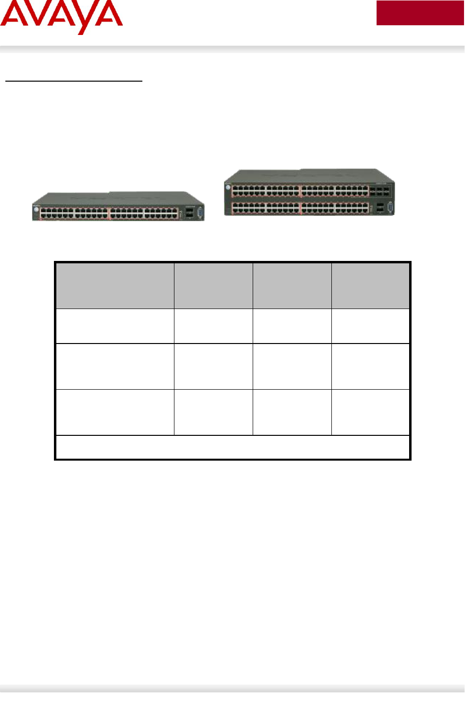
Avaya Inc. – External Distribution
190
avaya.com
Aug 2012
Ethernet Routing Switch 5600
The PoE capable ERS 5600 series stackable switches are available in a 48-port and a 96-port version.
The ERS 5600 offers built-in, hot swappable redundant power supply options in both AC and DC
varieties. It is also capable of providing full 15.4watts per port on every port in the switch along with full
N+1 redundant power simultaneously. The available configurations for power options are specified in
Table 16.
Table 16: ERS 5600 Power over Ethernet Options
Switch Model
PoE with one
power supply
PoE with two
power
supplies
PoE with three
power
supplies
ERS 5650TD-PWR
(600W)
370 watts total
7.7 watts/port
740 watts total
15.4 watts/port
N/A
ERS 5650TD-PWR
(1000W)
740 watts total
15.4 watts/port
740 watts total
* 15.4
watts/port
N/A
ERS 5698TFD-PWR
(1000W)
740 watts total
7.7 watts/port
1480 watts total
15.4 watts/port
1480 watts total
* 15.4
watts/port
* Full 15.4 watts on every port with N+1 power redundancy
ERS 5650TD-PWR
ERS 5698TFD-PWR
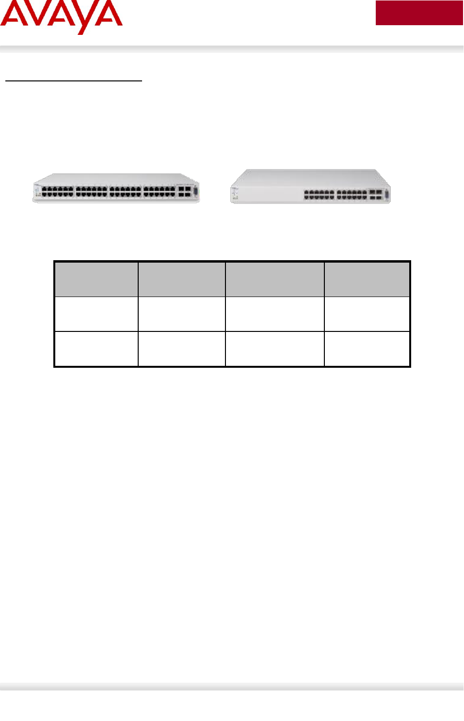
Avaya Inc. – External Distribution
191
avaya.com
Aug 2012
Ethernet Routing Switch 5500
The PoE capable ERS 5520 stackable switch is available in both a 24-port and a 48-port version. The
ERS 5520 provides up to 320 watts per switch on standard 110/240 VAC power. To provide more power
and/or redundant power, use the ERS Redundant Power Supply 15 (RPS 15) to augment the ERS 5520.
The RPS 15 can support up to three ERS 5520 switches. The available configurations for power options
are specified in Table 17.
Table 17: ERS 5500 Power over Ethernet Options
Switch Model
PoE on
Standard AC
RPS 15 Power
Sharing
RPS 15 RPSU
ERS ERS-24T-
PWR
320 watts total
13.3 watts/port
740 watts total
15.4 watts/port
320 watts total
13.3 watts/port
ERS 5520-48T-
PWR
320 watts total
6.7 watts/port
740 watts total
15.4 watts/port
320 watts total
6.7 watts/port
ERS 5520-48T-PWR
ERS5530-24T-PWR
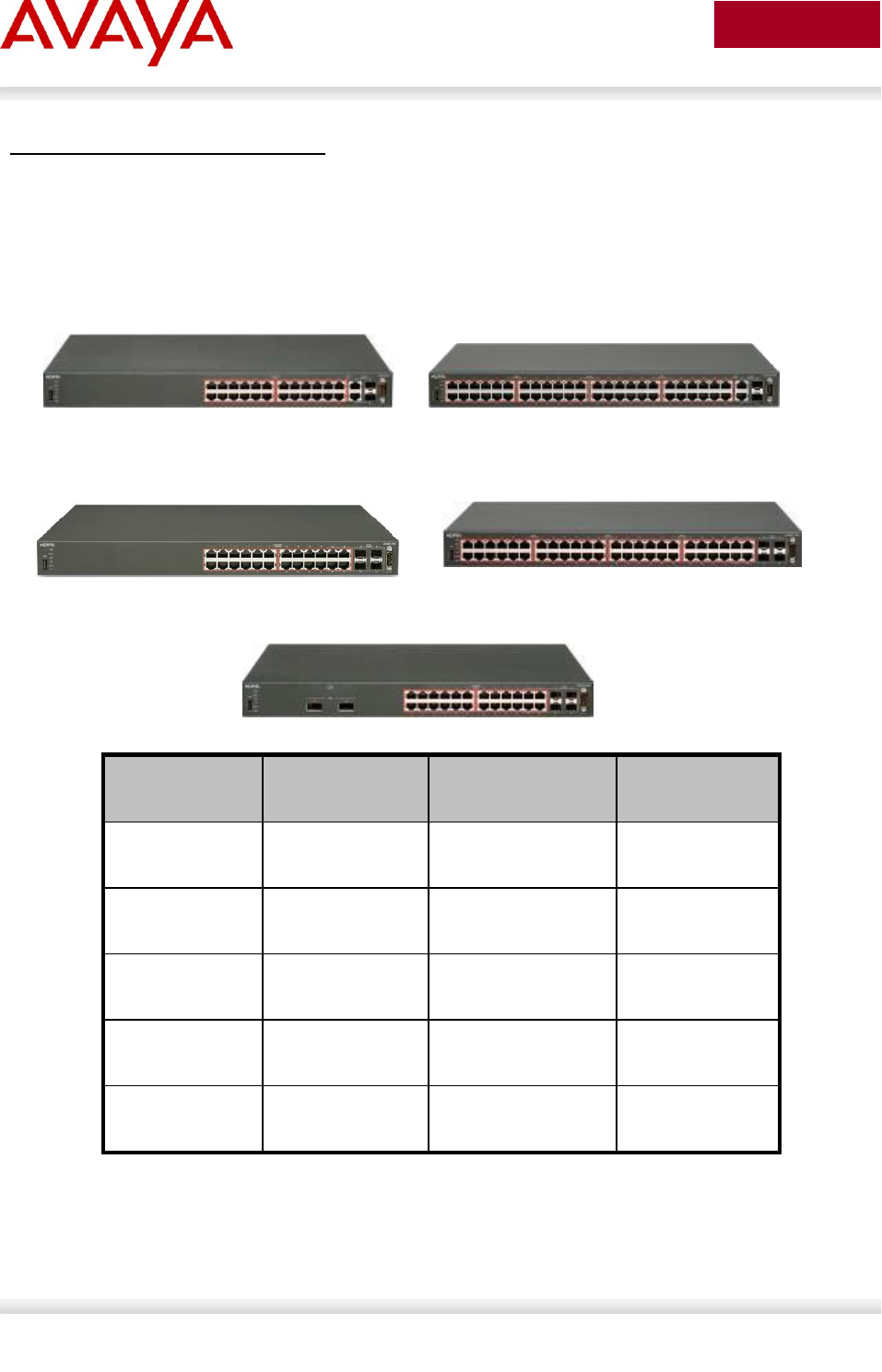
Avaya Inc. – External Distribution
192
avaya.com
Aug 2012
Ethernet Routing Switch 4000 - POE
The PoE capable ERS 4000 stackable switches are available in 10/100 and 10/100/1000 48-port
versions. The ERS 4000 provides up to 370 watts per switch on standard 110/240 VAC power. To
provide more power and/or redundant power, use the ERS Redundant Power Supply 15 (RPS 15) to
augment the ERS 4000. The RPS 15 can support up to three ERS 4000 switches. The available
configurations for power options are specified in Table 18.
Table 18: ERS 4000 Power over Ethernet Options
Switch Model
PoE on
Standard AC
RPS 15 Power
Sharing
RPS 15 RPSU
ERS 4526T-
PWR
370 watts total
15.4 watts/port
740 watts total
15.4 watts/port
370 watts total
15.4 watts/port
ERS 4550T-
PWR
370 watts total
7.7 watts/port
740 watts total
15.4 watts/port
370 watts total
7.7 watts/port
ERS 4524GT-
PWR
360 watts total
15.0 watts/port
740 watts total
15.4 watts/port
360 watts total
15.0 watts/port
ERS 4548GT-
PWR
320 watts total
6.7 watts/port
740 watts total
15.4 watts/port
320 watts total
6.7 watts/port
ERS 4526GTX-
PWR
360 watts total
15.0 watts/port
740 watts total
15.4 watts/port
360 watts total
15.0 watts/port
ERS 4526T-PWR
ERS 4550T-PWR
ERS 4524GT-PWR
ERS 4548GT-PWR
ERS 4526GTX-PWR
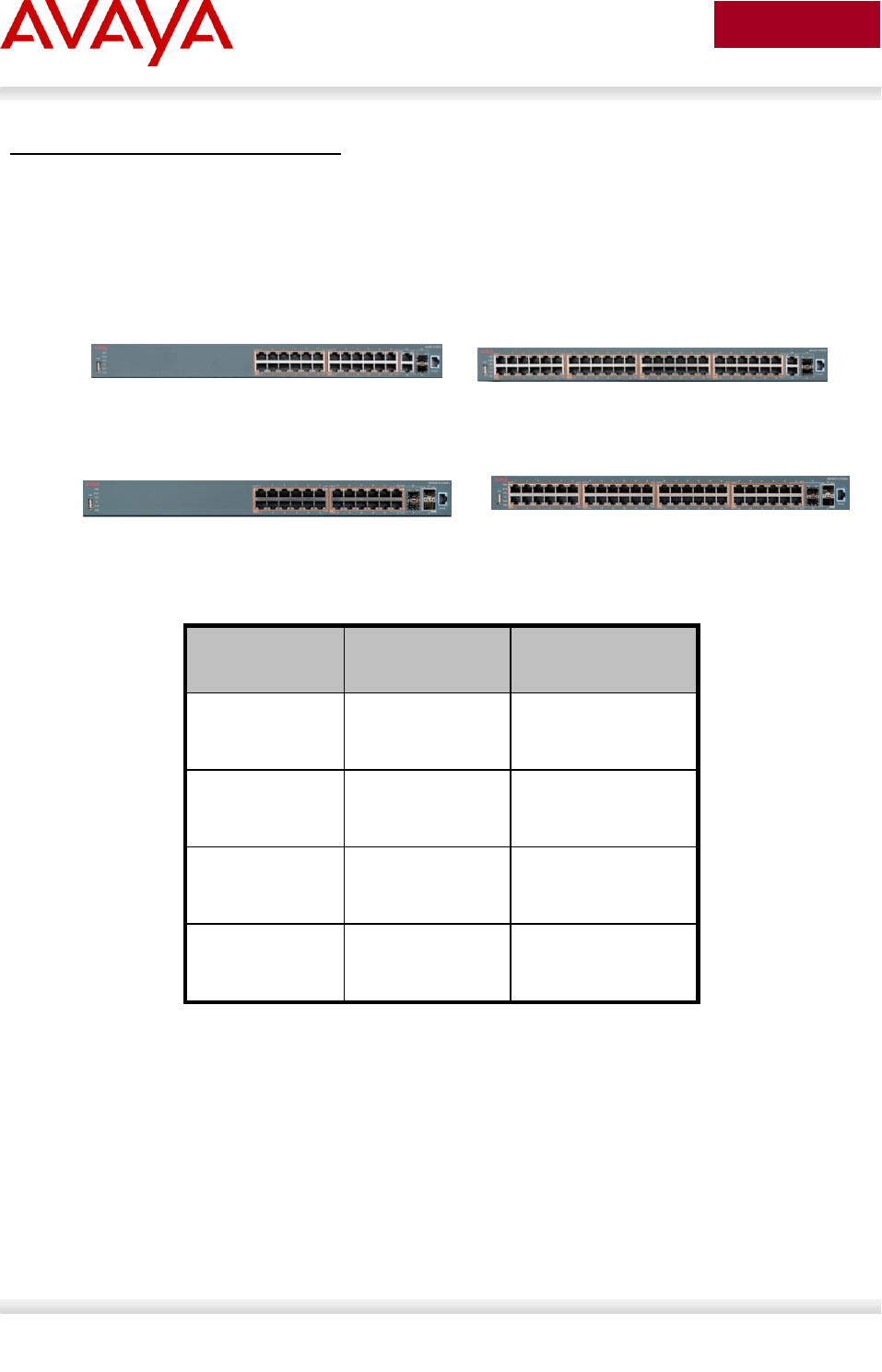
Avaya Inc. – External Distribution
193
avaya.com
Aug 2012
Ethernet Routing Switch 4000 – POE+
The PoE+ capable ERS 4000 stackable switches are available in 10/100 and 10/100/1000 24-port and
48-port versions supporting 802.3af PoE and 802.3at PoE+. The ERS 4000 PoE+ models offer built-in,
hot swappable redundant power supply options. Up to 855 watts per switch is supported using one 1000w
power supply or up to 1855 watts with two power supplies. The available configurations for power options
are specified in Table 19.
Table 19: ERS 4000 Power over Ethernet Plus Options
Notes:
All models can provide full 802.3af 15.4 watts per port with 1 PSU installed (a second PSU
provides full redundancy).
Both 26 port models can provide full 802.3at 32.4 watts per port with 1 PSU installed (a second
PSU provides full redundancy).
To provide the maximum of 32.4 watts for 802.3at PoE+ across all ports, the 50 port models
needs a second power supply to be installed. If one power supply should be removed or fail, then
the switch will prune utilization back to a maximum of 855 watts.
Switch Model
PoE with one
Power Supply
PoE with two
Power Supplies
ERS 4526T-
PWR+
855 watts total
32.4 watts/port
855 watts total
32.4 watts/port
ERS 4550T-
PWR+
855 watts total
32.4 watts/port
855 watts total
32.4 watts/port
ERS 4524GTS-
PWR+
855 watts total
32.4 watts/port
855 watts total
32.4 watts/port
ERS 4550GTS-
PWR+
855 watts total
32.4 watts/port
855 watts total
32.4 watts/port
ERS 4526T-PWR+
ERS 4550T-PWR+
ERS 4526GTS-PWR+
ERS 4550GTS-PWR+
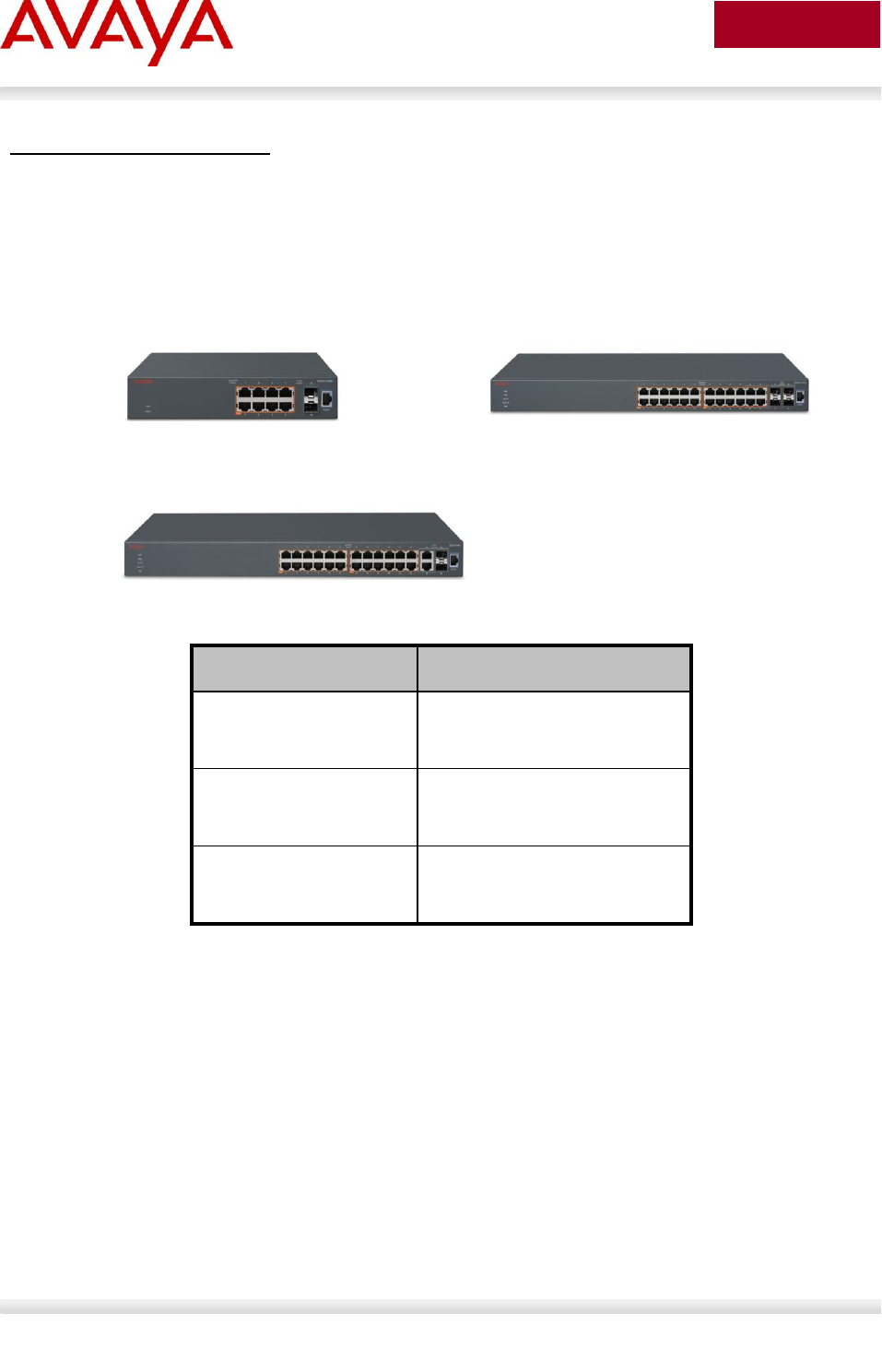
Avaya Inc. – External Distribution
194
avaya.com
Aug 2012
Ethernet Routing Switch 3500
The PoE+ capable ERS 3500 stackable switches are available in 10/100 and 10/100/1000 8-port and 24-
port versions supporting 802.3af PoE and 802.3at PoE+. The ERS 3500 PoE+ models offer built-in, hot
swappable redundant power supply options. Up to 855 watts per switch is supported using one 1000w
power supply or up to 1855 watts with two power supplies. The available configurations for power options
are specified in Table 20.
Table 20: ERS 3500 Power over Ethernet Plus Options
Notes:
The 3510GT-PWR+ supports fanless mode (silent) operation mode as well as a normal mode
deliverying full PoE budget with fan operational
o Low Power Budget Mode: this sets the maximum PoE budget to 60W and disables the
fan from operating – “fanless” mode.
o High Power Budget Mode: this sets the maximum PoE budget to 170W and normal fan
operation occurs – “normal” mode (default mode)
Switch Model
PoE on Standard AC
ERS 3510T-PWR+
60W or 170W watts total
7.5 or 21.25 watts/port
ERS 3524GT-PWR+
370 watts total
15.4 watts/port
ERS 3526T-PWR+
370 watts total
15.4 watts/port
ERS 3510T-PWR+
ERS 3524GT-PWR+
ERS 3526T-PWR+
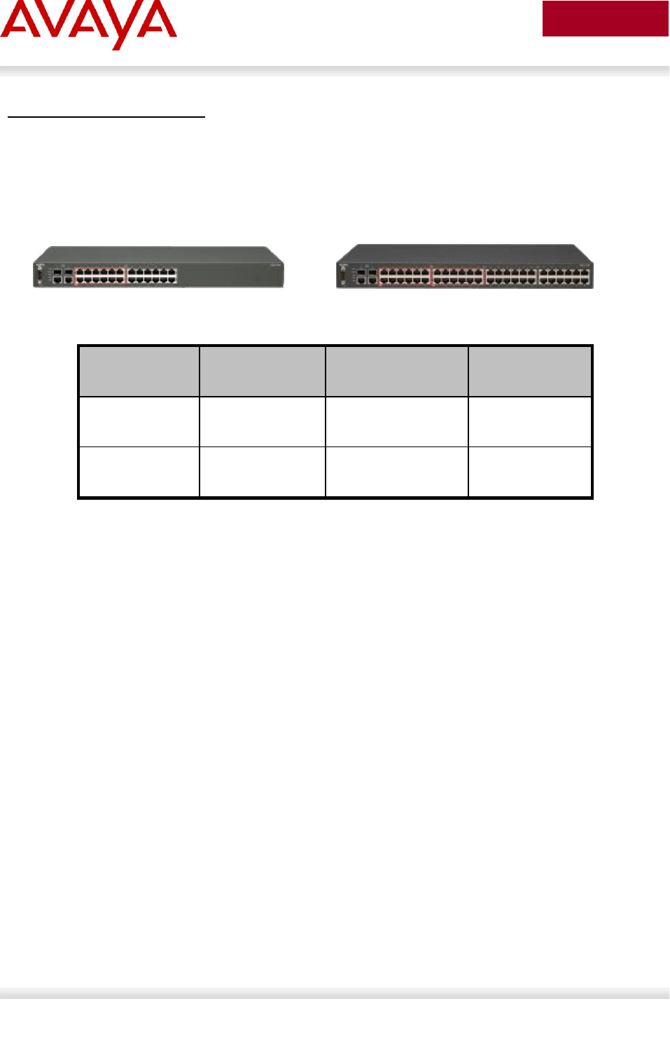
Avaya Inc. – External Distribution
195
avaya.com
Aug 2012
Ethernet Routing Switch 2500
The PoE capable ERS 2500 switches are available in both a 24-port and a 48-port version. With both of
these ERS 2500 switches, PoE is provided on half the ports (ports 1-12 of the 24 port switch and ports 1-
24 on the 48 port switch). The ERS 2500 provides up to 165 watts per switch on standard 110/240 VAC
power. The ERS 2500 does not support a redundant power option. The available configurations for power
options are specified in Table 20.
Table 21: ERS 2500 Power over Ethernet Options
Switch Model
PoE on
Standard AC
RPS 15 Power
Sharing
RPS 15 RPSU
ERS 2526T-
PWR
165 watts
N/A
N/A
ERS 2550T-
PWR
165 watts
N/A
N/A
ERS 2526T-PWR
ERS 2550T-PWR
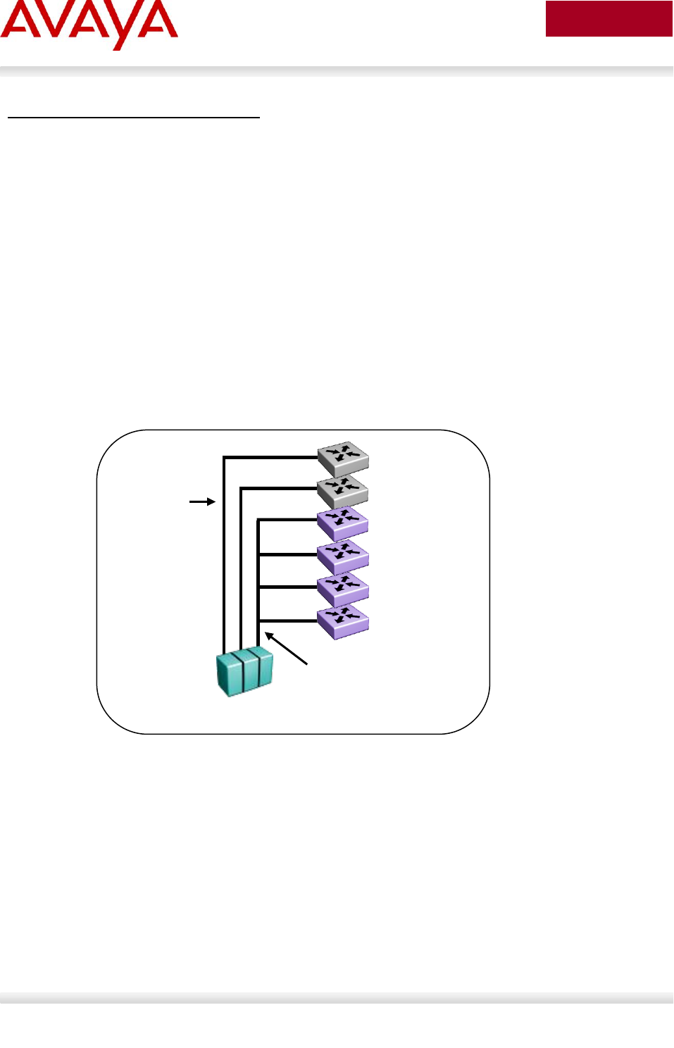
Avaya Inc. – External Distribution
196
avaya.com
Aug 2012
Redundant Power Supply 15 (RPS 15)
The RPS 15 provides redundant power to the Avaya stackable Ethernet switches (both PoE and non-
Poe). The RPS 15 is comprised of the following components:
RPS 15 Chassis (supports up to three 600 watt power supplies)
600 Watt Power Supply
DC-DC Converter (only required for some switches – see table below)
DC cable to connect power supply to Ethernet switch
The RPS 15 supports two different DC cable types. The first (AA0005018) is used with all Ethernet
switches that have a built-in DC-DC converter and can provide a single power connection to one Ethernet
switch. The second type of cable, which comes in two models (AA0005020 – 25’ and AA0005021 – 10’) is
used with all Ethernet switches that require the addition of the DC-DC converter module. This second
cable type can provide a single power connection for up to four Ethernet switches.
The RPS 15 can be added to an Ethernet switch or stack of Ethernet switches while the switches are
powered up and running. There is no need to power off the switch to connect the RPS 15 cable.
Figure 17: Redundant Power Supply 15 (RPS15)
ERS 5520
RPS 15 with Three
600w Power Supplies
ERS 5520
ERS 5510
ERS 5510
ERS 5510
ERS 5510
DC Cable
AA0005020 (25’)
Or
DC Cable
AA0005021 (10’)
DC Cable
AA0005018
Avaya Inc. – External Distribution
197
avaya.com
Aug 2012
Table 21 provides information on the required components when using the RPS 15 with the various
Ethernet switching options.
Table 22: RPS 15 Configuration Options
Switch Model
PoE
Capable
Switch
RPS 15
Chassis
RPS 15 600w
Power Supply
DC-DC
Converter
DC Cable
for Built-In
Converter
10’ or 25’
DC Cable
ERS 5510
No
1
1 per 4 switches
Required
N/A
Required
ERS 5520
Yes
1
1
Built-In
Required
N/A
ERS 5530
No
1
1
Built-In
Required
N/A
ERS 4526FX
No
1
1 per 4 switches
Required
N/A
Required
ERS 4526T
No
1
1 per 4 switches
Required
N/A
Required
ERS 4526T-PWR
Yes
1
1
Built-In
Required
N/A
ERS 4550T
No
1
1 per 4 switches
Required
N/A
Required
ERS 4550T-PWR
Yes
1
1
Built-In
Required
N/A
ERS 4524GT
No
1
1 per 4 switches
Required
N/A
Required
ERS 4524GT-
PWR
Yes
1
1
Built-In
Required
N/A
ERS 4548GT
No
1
1 per 4 switches
Required
N/A
Required
ERS 4548GT-
PWR
Yes
1
1
Built-In
Required
N/A
ERS 4526GTX
No
1
1 per 4 switches
Required
N/A
Required
ERS 4526GTX-
PWR
Yes
1
1
Built-In
Required
N/A
ES 470-24T-
PWR
Yes
1
1
Built-In
Required
N/A
ES 470-48T-
PWR
Yes
1
1
Built-In
Required
N/A
ES 470-24T
No
1
1 per 4 switches
Required
N/A
Required
ES 470-48T
No
1
1 per 4 switches
Required
N/A
Required
Avaya Inc. – External Distribution
198
avaya.com
Aug 2012
6.3 Configuring PoE
6.3.1 Stackable Ethernet Routing Switch
By default, PoE Power Management is enabled by default with all PoE ports power enabled at power up.
The following commands apply to the switches listed in the previous section.
6.3.1.1 Displaying PoE Status and Statistics and setting global
settings
To display the PoE status and statistics, you can use the following commands:
To view the Global PoE status, enter the following command:
ERS-Stackable(config)#show poe-main-status
ERS-Stackable(config)#show poe-main-status unit <1-8>
To view the PoE port status, enter the following command:
ERS-Stackable(config)#show poe-port-status
ERS-Stackable(config)#show poe-port-status <port|unit/port>
To view power used on a PoE port, enter the following command:
ERS-Stackable(config)#show poe-power-measurement
ERS-Stackable(config)#show poe-power-measurement <port|unit/port>
To change the trap threshold, enter the following commands:
ERS-Stackable(config)#poe poe-power-usage-threshold <1-99>
ERS-Stackable(config)#poe poe-power-usage-threshold unit <1-8> <1-99>
To set the PD detection type, enter the following command:
ERS-Stackable(config)#poe poe-pd-detect-type <802dot3af | 802dot3ad_and_legacy>
ERS-Stackable(config)#poe poe-pd-detect-type unit <1-8> <802dot3af|
802dot3ad_and_legacy>
To set the PD detection type, enter the following command for the ERS 4000 PoE+ and
ERS 3500 PoE+switches; the 3500, 4500 and 4800 PWR+ models that support PoE+,
according to the IEEE 802.3at standard, and can deliver power up to 32W, as opposed to
16W for the 4500 PWR legacy units:
ERS-Stackable(config)#poe poe-pd-detect-type <802dot3af |
802dot3ad_and_legacy802dot3at | 802dot3at_and_legacy>
ERS-Stackable(config)#poe poe-pd-detect-type unit <1-8> <802dot3af |
802dot3ad_and_legacy802dot3at | 802dot3at_and_legacy>

Avaya Inc. – External Distribution
199
avaya.com
Aug 2012
ERS 3500: To change the PoE power mode
ERS3500(config)#poe power-mode {low-power-budget | high-power-budget}
To default the operating mode (low power budget):
ERS3500(config)#default poe power-mode
ERS 3500: To display the Power Mode setting
ERS3500(config)#show poe-main-status
PoE Main Status - Stand-alone
--------------------------------------------------
Power Mode : Low Power Budget
Available DTE Power : 60 Watts
DTE Power Status : Normal
DTE Power Consumption : 0 Watts
DTE Power Usage Threshold : 80 %
PD Detect Type : 802.3at and Legacy
Power Source Present : AC Only
AC Power Status : Present
DC Power Status : Not Present
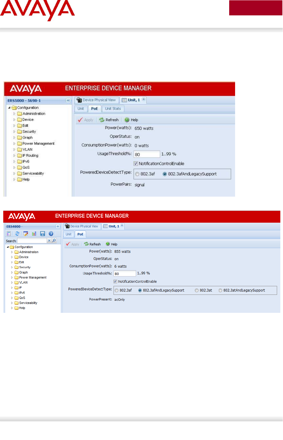
Avaya Inc. – External Distribution
200
avaya.com
Aug 2012
EDM:
To view or configure the PoE global status, enter the following:
Using EDM, go to the Device Physical View, right-click the switch and select Edit
Go to the PoE tab
PoE+
To view or configure the PoE port status, enter the following:
Using EDM, go to the Device Physical View, right-click the port or ports and select Edit
Go to the PoE tab
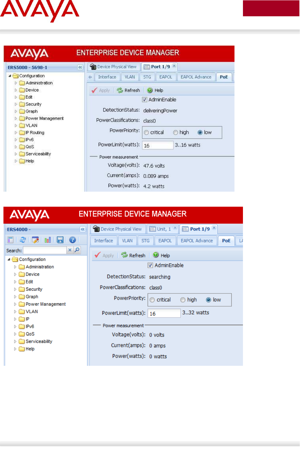
Avaya Inc. – External Distribution
201
avaya.com
Aug 2012
PoE+
Avaya Inc. – External Distribution
202
avaya.com
Aug 2012
6.3.1.2 PoE Settings
ACLI
By default, all ports support 802.3af Power Class of 0 providing up to 15.4W per port. The 4500 and 4800
PWR models that support PoE+, according to the IEEE 802.3at standard, and can deliver power up to
32W, as opposed to 16W for the 4500 PWR legacy units:
To disable PoE at a port level, enter the following commands:
ERS-Stackable(config)#interface fastEthernet all
ERS-Stackable(config-if)#poe poe-shutdown port <port #>
ERS-Stackable(config-if)#exit
To configure the PoE power level, enter the following commands where the value <3-16> is
the power limit in watts:
ERS-Stackable(config)#interface fastEthernet all
ERS-Stackable(config-if)#poe poe-limit port <port #> <3-16>
ERS-Stackable(config-if)#exit
To set the PoE port priority, enter the following commands:
ERS-Stackable(config)#interface fastEthernet all
ERS-Stackable(config-if)#poe poe-priority port <port #> <low|high|critical>
ERS-Stackable(config-if)#exit
For the ERS 4000 PoE+ models:
ERS-Stackable(config)#interface fastEthernet all
ERS-Stackable(config-if)#poe poe-limit port <port #> <3-32>
ERS-Stackable(config-if)#poe poe-priority port <port #> <low|high|critical>
ERS-Stackable(config-if)#exit
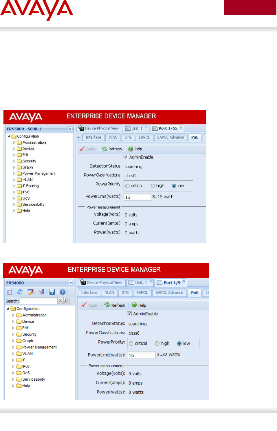
Avaya Inc. – External Distribution
203
avaya.com
Aug 2012
EDM:
To disable PoE on a port via EDM, perform the following:
Go to the Device Phyical View
Right-click on the port and select Edit
o If you wish to configure multiple port, press the Ctrl key and left click each port you wish to
configure
Go to the PoE tab
POE+

Avaya Inc. – External Distribution
204
avaya.com
Aug 2012
6.3.2 Ethernet Routing Switch 8300
By default, PoE Power Management is enabled with all PoE ports power enabled at power up.
6.3.2.1 Displaying PoE Status and Statistics
To display the PoE status and statistics, you can use the following commands:
To view the Global PoE status per module, enter the following command:
CLI
ERS-8310:5# show poe card info
ACLI
ERS-8310:5#show poe main-status
To view the PoE port status, enter the following command:
CLI
ERS-8310:5# show poe port info
ACLI
ERS-8310:5#show
To view the PoE port stats, enter the following command:
CLI
ERS-8310:5# show poe port stats
ACLI
ERS-8310:5#show poe port-status
To view power used on a PoE port, enter the following command:
CLI
ERS-8310:5# show poe port power-measurement <slot/port>
ACLI
ERS-8310:5#show poe port-stats
To view the PoE system status, enter the following command:
CLI
ERS-8310:5# show poe sys info
ACLI
ERS-8310:5#show poe sys-status
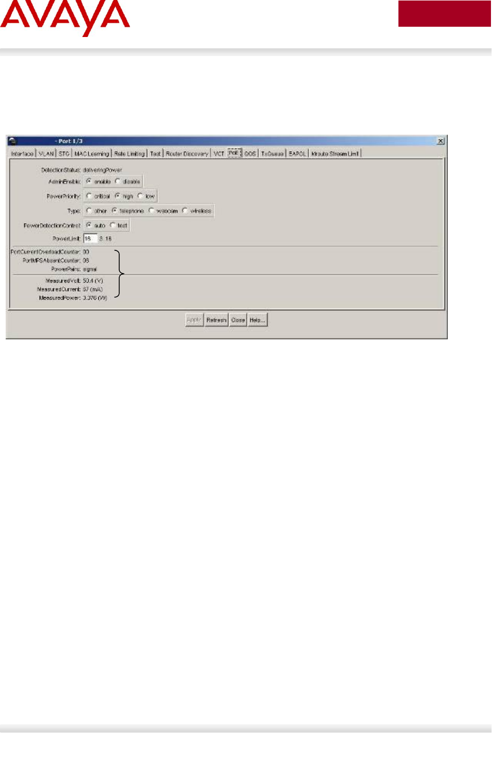
Avaya Inc. – External Distribution
205
avaya.com
Aug 2012
JDM - Port Level
Right-click on the port> Edit>PoE
o If you wish to configure multiple ports, press the Ctrl key and left click each port you wish to
configure
PoE Statistics per port
Avaya Inc. – External Distribution
206
avaya.com
Aug 2012
6.3.2.2 PoE Settings
To disable PoE on a port, enter the following command:
CLI
ERS-8310:5# config poe port <slot/port> admin disable
ACLI
ERS-8310:5(config)#interface fastEthernet <slot/port>
ERS-8310:5(config-if)#poe shutdown
ERS-8310:5(config-if)#exit
To disable PoE on a slot basis, enter the following command:
CLI
ERS-8310:5# config poe card <slot #> admin disable
ACLI
ERS-8310:5(config)# poe shutdown slot <slot #>
To limit PoE power at a port level, enter the following command:
CLI
ERS-8310:5# config poe port <slot/port> power-limit <3-16>
ACLI
ERS-8310:5(config)#interface fastEthernet <slot/port>
ERS-8310:5(config-if)# poe limit <3-16>
ERS-8310:5(config-if)#exit
To limit PoE power at a module level from 37 to 800W, enter the following command:
CLI
ERS-8310:5# config poe card 1 power-limit <slot #> <37-800>
ACLI
ERS-8310:5(config)#poe limit slot <slot #> <37-800>
To set the PoE slot priority, enter the following command:
CLI
ERS-8310:5# config poe card <card #> power-priority <low|high|critical>
ACLI
ERS-8310:5(config)#poe priority slot <slot #> <low|high|critical>
To set the PoE priority at a port level, enter the following command:
CLI

Avaya Inc. – External Distribution
207
avaya.com
Aug 2012
ERS-8310:5# config poe port <slot/port> power-priority <low|high|critical>
ACLI
ERS-8310:5(config)#interface fastEthernet <slot/port>
ERS-8310:5(config-if)#poe priority <low|high|critical>
ERS-8310:5(config-if)#exit
To set the PoE detection control, enter the following command. The PSE Power
Management Admin Status is enabled by default with power detection set on all ports to
auto mode. Power detection can be set for either auto or test where test mode implies the
port is in continuous discovery without supplying power. Under normal operation, the
Ethernet Routing Switch 8300 will not supply power unless a PD (Powered Device) is
requesting power. To change the detection control, enter the following commands.
CLI
ERS-8310:5# config poe port <slot/port> power-detection-control <auto|test>
ACLI
ERS-8310:5(config)#interface fastEthernet <slot/port>
ERS-8310:5(config-if)#poe detect-control <auto|test>
ERS-8310:5(config-if)#exit
To set the Power Device (PD) Type, enter the following command:
CLI
ERS-8310:5# config poe port 1/1 type <other|telephone|webcam|wireless>
ACLI
ERS-8310:5(config)#interface fastEthernet <slot/port>
ERS-8310:5(config-if)# poe type <other|telephone|webcam|wireless>
ERS-8310:5(config-if)#exit
To set the PoE Trap Threshold , enter the following command:
CLI
ERS-8310:5# config poe card <slot #> power-usage-threshold <0-99>
ACLI
ERS-8310:5(config)# poe usage-threshold slot <slot #> <0-99>

Avaya Inc. – External Distribution
208
avaya.com
Aug 2012
To disable PoE threshold notification , enter the following command:
CLI
ERS-8310:5# config poe card notification-control <enable|disable>
ACLI
ERS-8310:5(config)# no poe notification slot <slot#>
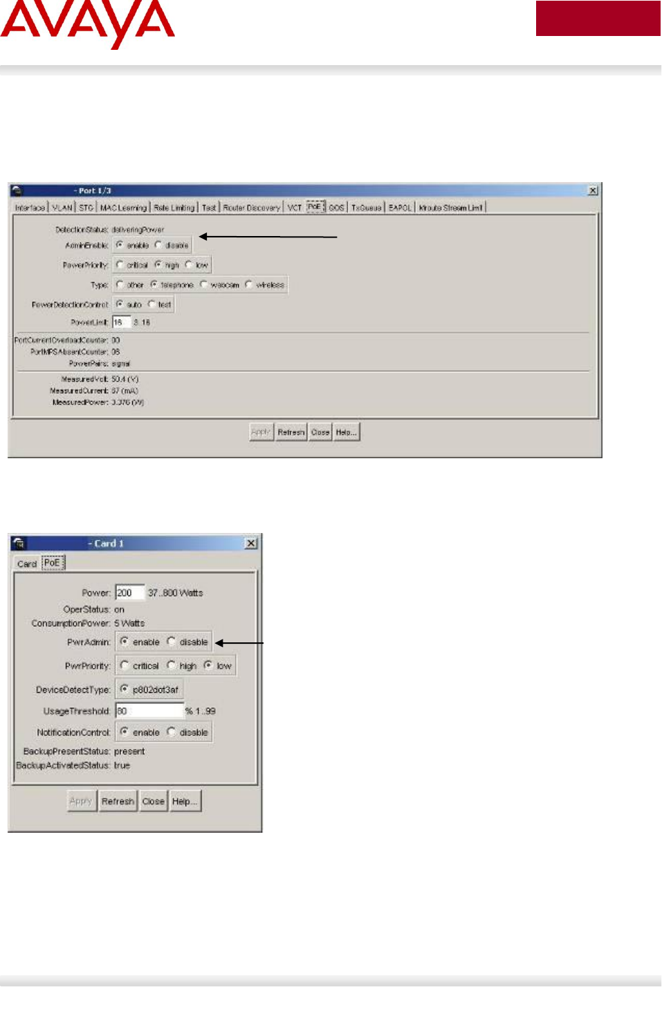
Avaya Inc. – External Distribution
209
avaya.com
Aug 2012
JDM – Port Level:
Right-click on the port> Edit>PoE
If you wish to configure multiple ports, press the Ctrl key and left click each port you wish to
configure
JDM – Card Level:
Select slot that you wish to configure, it should be high-lighted in a yellow box
Right-click the card and select Edit>PoE
Enable/disable PoE power per port
Enable/disable PoE power per slot

Avaya Inc. – External Distribution
210
avaya.com
Aug 2012
7. Avaya Enery Saver
You can use Avaya Energy Saver (AES) to reduce network infrastructure power consumption without
impacting network connectivity. AES uses intelligent switching capacity reduction in off-peak mode to
reduce direct power consumption by up to 40%. AES can also use Power over Ethernet (PoE) port power
priority levels to shut down low priority PoE ports and provide more power savings.
The power consumption savings of each switch is determined by the number of ports with AES enabled
and by the power consumption of PoE ports that are powered off. If AES for a port is set to disabled, the
port is not powered off, irrespective of the PoE configuration. AES turns off the power to a port only when
PoE is enabled globally, the port has AES is enabled, and the PoE priority for the port is configured to
low.
You can schedule AES to enter lower power states during specified periods of time. These time periods
can be a complete week, complete weekend, or individual days.
Because AES reduces the port speed to 10 Mbps full duplex when AES is activated, the IP phone will
experience a short loss of traffic. Depending on the Avaya IP Phone model, this loss can be anywhere
from 3 to 15 seconds as shown in the following chart.
Avaya IP Phone
Duration of loss of traffic
Setup
1600, 4600, 9600 Series
3-5 seconds
Using double DHCP
3-5 seconds
LLDP-MED with Network Policy
25 seconds
ADAC with LLDP-MED
1100, 1200, 2000 Series
5-15 seconds
Using double DHCP
8-13 seconds
LLDP-MED with Network Policy
70 seconds
ADAC with LLDP-MED
The Avaya 1600, 4600, and 9600 series are faster to recover when AES is activated as
they cache the VLAN and IP address. The 1100, 1200, and 2000 series will always
perform a DHCP request when AES is activated even if the cached IP setting is enabled
– this setting is only used when the IP Phone cannot reach the DHCP server.

Avaya Inc. – External Distribution
211
avaya.com
Aug 2012
8. QoS
8.1 Interface Roles – Stackable Ethernet Routing
Switch
The Ethernet Routing Switch ports are classified into one of three categories which are trusted, untrusted,
or unrestricted. The classifications of trusted, untrusted, and unrestricted actually apply to groups of ports
(interface groups). These three categories are also referred to as interface classes. In your network,
trusted ports are usually connected to the core of the DiffServ network, and untrusted ports are typically
access links that are connected to end stations. Unrestricted ports can be either access links or
connected to the core network.
At factory default, all ports are considered untrusted. However, for those interface groups created, the
default is unrestricted.
Because a port can belong to only one interface group, a port is classified as trusted, untrusted, or
unrestricted. These types are also referred to as interface classes.
The default processing of trusted and untrusted interfaces is as follows:
Trusted interfaces — IPv4 traffic received on trusted interfaces is re-marked at the layer 2 level,
that is, the 802.1p user priority value is updated based on the DSCP value in the packet at
ingress and the installed DSCP-to-CoS mapping data. The DSCP value is not updated. On the
5500 Series switch, remapping occurs, by default, only for standardized DSCP values (for
example, EF, AFXX) and any proprietary Avaya values. On the 5600 Series switch, remapping
occurs for all DSCP values. The DSCP values that are remapped are associated with a zero
802.1p user priority value in the DSCP-to-COS Mapping Table. The 5600 Series switch uses a
hardware based DSCP table to support Trusted processing. No policies or filters are consumed
by the 5600 Series.
Untrusted interfaces — IPv4 traffic received on untrusted interfaces is re-marked at the layer 3
level—that is, the DSCP value is updated. The new DSCP value is determined differently
depending on whether the packet is untagged or tagged:
o Untagged frames
The DSCP value is derived using the default port priority of the interface receiving the
ingressing packet. This default port priority is used to perform a lookup in the installed CoS-
to-DSCP mapping table.
The 802.1p user priority value is unchanged—that is, the default port priority determines this
value.
(Thus, the DSCP value on untagged frames on untrusted interfaces is updated using the
default port priority of the ingress interface; the user sets the default port priority).
o Tagged frames
The DSCP value is re-marked to indicate best-effort treatment is all that is required for this
traffic.
The 802.1p user priority value is updated based on the DSCP-to-CoS mapping data
associated with the best effort DSCP, which is 0.
Table 23 "Default QoS fields by class of interface—IPv4 only" shows the default guidelines the switch
uses to re-mark various fields of IPv4 traffic (and layer 2 traffic matching IPv4) based on the class of the
interface. These actions occur if the user does not intervene at all; they are the default actions of the
switch.

Avaya Inc. – External Distribution
212
avaya.com
Aug 2012
Action
Trusted
Untrusted
Unrestricted
DSCP
Does not
change
Tagged--Updates to 0 (Standard)
Untagged--Updates using mapping
table and port’s default QoS level value
Does not
change
IEEE
802.1p
Updates
based on
DSCP
mapping table
value
Updates based on DSCP
mapping table value
Tagged—Updates to 0
Untagged--Updates to port’s default
value
Does not
change
Table 23: Default QoS fields by class of interface—IPv4 only
By default, all ports are untrusted using the default role combination named allQoSPolicyIfcs. This can be
viewed by using the following command:
ERS-Stackable#show qos if-group
Role Interface Capabilities Storage
Combination Class Type
________________________________ ____________ ___________________ ___________
allQoSPolicyIfcs Untrusted Input 802, Input IP ReadOnly
$remediationIfcs Unrestricted Input 802, Input IP Other
$NsnaIfcs Unrestricted Input 802, Input IP Other
The following demonstrates several methods used to configure a simple layer 2 filter depending on if the
ports are configured as untrusted or trusted. In our example VLAN 220 will be used for the Voice VLAN
and VLAN 1000 as the data VLAN.
8.2 Default QoS Operations - ERS 8300
In regards to the ERS 8300, by default, both the DSCP and p-bit values are passed as-is. The p-bit value
determines the QoS level. If you wish to use the DSCP value instead of the p-bit value to determine the
QoS level, the port parameter trust-dscp should be enabled (in software versions prior to 4.1.3.1 and
4.2.0.1 on I/O modules other than the 8348GTX or 8348GTX-PWR, an ACL must be configured to trust
DSCP instead).
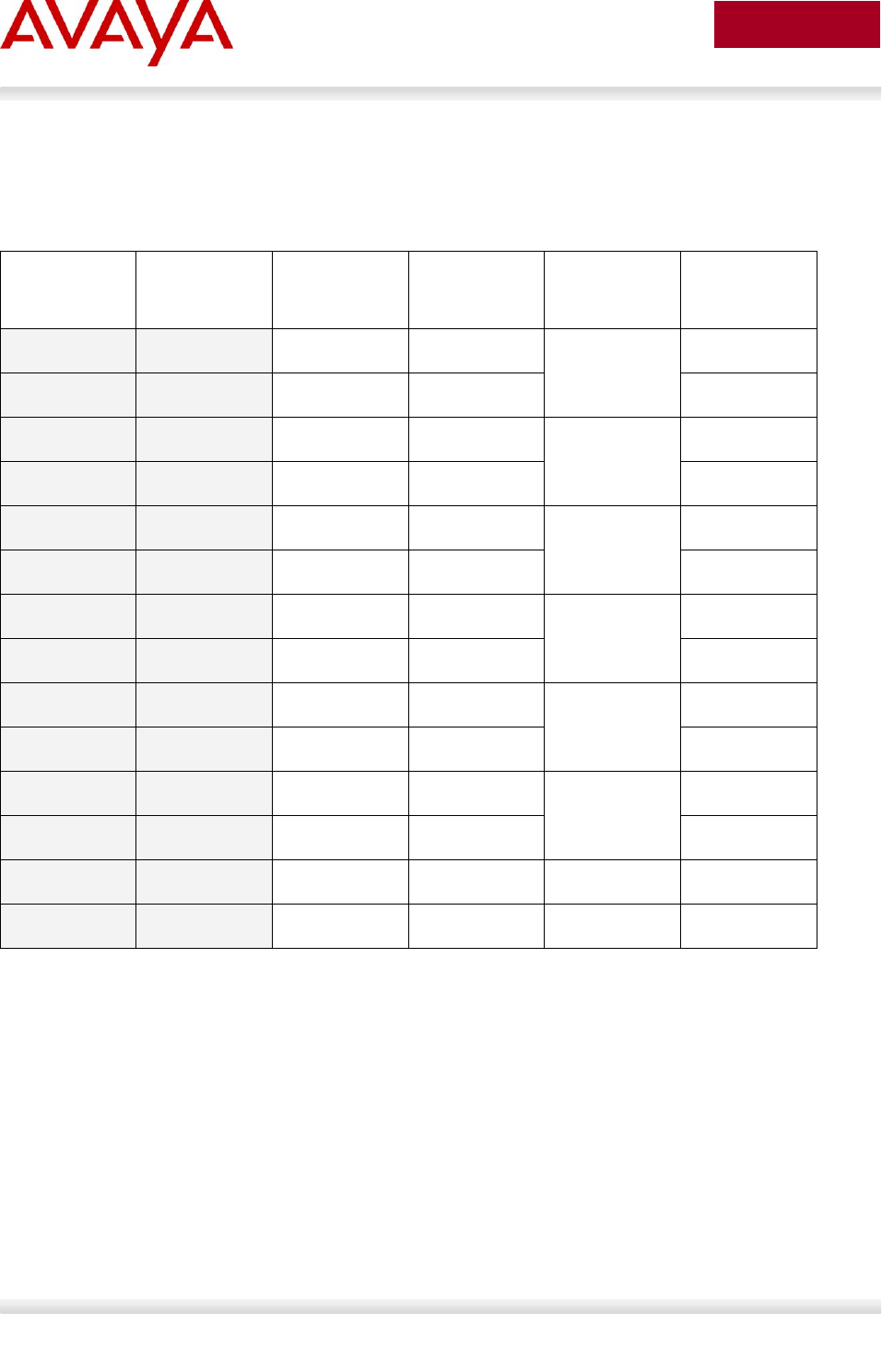
Avaya Inc. – External Distribution
213
avaya.com
Aug 2012
8.3 QoS Mapping
Table 24 display’s the default QoS Avaya service class mapping. This is the default mapping used with all
the Avaya switches mentioned in the TCG.
DSCP
TOS
Binary
Decimal
DSCP/ToS
NNSC
PHB
0x0
0x0
000000 00
0
Standard
CS0
0x0
0x0
000000 00
0
DE
0x8
0x20
001000 00
8/32
Bronze
CS1
0xA
0x28
001010 00
10/40
AF11
0x10
0x40
010000 00
16/64
Silver
CS2
0x12
0x48
010010 00
18/72
AF21
0x18
0x60
011000 00
24/96
Gold
CS3
0x1A
0x68
011010 00
26/104
AF31
0x20
0x80
100000 00
32/128
Platinum
CS4
0x22
0x88
100010 00
34/136
AF41
0x28
0xA0
101000 00
40/160
Premium
CS5
0x2E
0xB8
101110 00
46/184
EF
0x30
0xC0
110000 00
48/192
Network
CS6
0x38
0xE0
111000 00
56/224
Critical
CS7
Table 24: Avaya QoS Class Mappings

Avaya Inc. – External Distribution
214
avaya.com
Aug 2012
8.4 Queue Sets
8.4.1 Ethernet Routing Switch 2500
The ERS 2500 has four hardware queues which can be viewed by using the following ACLI command.
The first queue, strict priority, is always serviced first. The remaining three queues are serviced using a
weighted-round-robin (WRR) scheduler.
2526T-PWR#show qos queue-set
Set Queue General Bandwidth Absolute Bandwidth Service Size
ID ID Discipline (%) Bandwidth Allocation Order (Bytes)
(Kbps)
___ _____ _____________________ _________ _________ __________ _______ _______
4 1 Priority Queuing 100 0 Relative 1 184320
4 2 Weighted Round Robin 65 0 Relative 2 151552
4 3 Weighted Round Robin 26 0 Relative 2 135168
4 4 Weighted Round Robin 9 0 Relative 2 118784
The default priority mapping can be used by the issuing the following ACLI command.
2526T-PWR#show qos queue-set-assignment
Queue Set 4
802.1p Priority Queue
_______________ _____
0 4
1 4
2 4
3 4
4 4
5 3
6 1
7 2

Avaya Inc. – External Distribution
215
avaya.com
Aug 2012
The default DSCP to priority mapping can be viewed by issuing the following command.
2526T-PWR#show qos egressmap
DSCP 802.1p Priority Drop Precedence Name
____ _______________ _______________ ________________
0 0 High Drop Standard Service
1 0 High Drop Standard Service
2 0 High Drop Standard Service
3 0 High Drop Standard Service
8 2 High Drop Bronze Service
[…]
16 3 High Drop Silver Service
[…]
24 4 High Drop Gold Service
[…]
32 5 High Drop Platinum Service
[…]
40 6 Low Drop Premium Service
[…]
48 7 Low Drop Network Service
[…]
56 7 Low Drop Critical Service
[…]
63 0 High Drop Standard Service

Avaya Inc. – External Distribution
216
avaya.com
Aug 2012
8.4.3 Ethernet Routing Switch 3500
The ERS 3500 has four hardware queues which can be viewed by using the following ACLI command.
The first queue, strict priority, is always serviced first. The remaining three queues are serviced using a
weighted-round-robin (WRR) scheduler.
3524GT-PWR+#show qos queue-set
Set Queue General Bandwidth Absolute Bandwidth Service Size
ID ID Discipline (%) Bandwidth Allocation Order (Bytes)
(Kbps)
___ _____ _____________________ _________ _________ __________ _______ _______
4 1 Priority Queuing 100 Relative 1 184320
4 2 Weighted Round Robin 65 Relative 2 151552
4 3 Weighted Round Robin 26 Relative 2 135168
4 4 Weighted Round Robin 9 Relative 2 118784
The default priority mapping can be used by the issuing the following ACLI command.
3524GT-PWR+#show qos queue-set-assignment
Queue Set 4
802.1p Priority Queue
_______________ _____
0 4
1 4
2 4
3 4
4 4
5 3
6 1
7 2

Avaya Inc. – External Distribution
217
avaya.com
Aug 2012
The default DSCP to priority mapping can be viewed by issuing the following command.
3524GT-PWR+#show qos egressmap
DSCP 802.1p Priority Drop Precedence Name
____ _______________ _______________ ________________
0 0 High Drop Standard Service
1 0 High Drop Standard Service
2 0 High Drop Standard Service
3 0 High Drop Standard Service
8 2 High Drop Bronze Service
[…]
16 3 High Drop Silver Service
[…]
24 4 High Drop Gold Service
[…]
32 5 High Drop Platinum Service
[…]
40 6 Low Drop Premium Service
[…]
48 7 Low Drop Network Service
[…]
56 7 Low Drop Critical Service
[…]
63 0 High Drop Standard Service
The qos queue-set-assignment queue-set <1-32> 1p <0-7> queue <1-8> command gives the user the
ability to specify the queue to associate an 802.1p priority.
The show qos queue-set-assignment command displays in the ACLI the 802.1p priority to egress CoS
and QoS queue mapping for CoS setting.
3524GT-PWR+(config)#qos egressmap [name <policy-name>] ds <DSCP-value 0-63> 1p
<802.1P-value 0-7> dp <drop-precedence low-drop | high-drop> newds <mutated-DSCP-
value 0-63>
QoS DSCP mutation is a QoS feature which extends the trusted interface support to allow recolouring of
the DSCP values on egress utilising the mapping tables rather than filters. This feature enables the switch
to not only set the Class of Service, but to also recolour the DSCP value on egress without using any filter
resouces.

Avaya Inc. – External Distribution
218
avaya.com
Aug 2012
8.4.4 Ethernet Routing Switch 4000
Beginning with release 5.4, the ERS 4000 now supports up to 8 different queue sets with a buffering
sharing setting, and support for egress traffic shaping. Depending on the queue set, up to eight queues
are supported. The default settings include queue-set 2 supporting two strict queues with and a buffer
sharing setting of Large.
Egress CoS Queuing ACLI Commands
4000-PWR(config)#qos agent queue set <1-8>
4000-PWR#show qos queue-set
4000-PWR#show qos queue-set <1-8>
4000-PWR(config)#default qos agent queue-set
The qos agent queue set <1-8> command sets the egress CoS and QoS queue mode (1-8) in which the
switch will operate. This parameter is global and requires a reset to activate a change. Please note,
although up to 32 queue sets shown using the show qos queue-set, you can only select one of the first
eight queue sets.
The show qos queue-set command displays the queue set configuration. The display includes the
general discipline of the queue, the percent bandwidth (Kbps), and the queues size in bytes.
The default qos agent queue-set command will default the egress CoS and QoS queue set back to queue
mode is 2.
4000-PWR(config)# qos agent buffer <large | maximum | regular>
4000-PWR(config)#show qos agent
4000-PWR(config)#qos agent reset-default
The qos agent buffer <regular | large | maximum > command allows the user to specify the level of
resource sharing on the switch. This parameter is global and requires a reset to activate a change.
The show qos agent command displays the current attributes for egress CoS and QoS queue mode,
resource sharing mode, and QoS NVRAM commit delay.
The qos agent reset-default command resets QoS to its configuration default.
4000-PWR(config)#qos queue-set-assignment queue-set <1-32> 1p <0-7> queue <1-8>
4000-PWR#show qos queue-set-assignment
4000-PWR#show qos queue-set-assignment queue-set <1-32>
The qos queue-set-assignment queue-set <1-32> 1p <0-7> queue <1-8> command gives the user the
ability to specify the queue to associate an 802.1p priority.
The show qos queue-set-assignment command displays in the ACLI the 802.1p priority to egress CoS
and QoS queue mapping for CoS setting.

Avaya Inc. – External Distribution
219
avaya.com
Aug 2012
4000-PWR(config)#qos egressmap [name <policy-name>] ds <DSCP-value 0-63> 1p
<802.1P-value 0-7> dp <drop-precedence low-drop | high-drop> newds <mutated-DSCP-
value 0-63>
QoS DSCP mutation is a QoS feature (release 5.4 or higher) which extends the trusted interface support
to allow recolouring of the DSCP values on egress utilising the mapping tables rather than filters. This
feature enables the switch to not only set the Class of Service, but to also recolour the DSCP value on
egress without using any filter resouces.
In software releases prior to v5.4 the ERS4000 supported one queue set, queue set 4,
made up of four queues with maximum allocation.
QoS Egress Queue Traffic Shaping
4000-PWR(config)# qos if-queue-shaper port <port> queue <1-8> shape-rate <64-10230000>
shape-min-rate <64-10230000>
4000-PWR(config)#show qos if-queue-shaper port <port> {queue <1-8>}
Egress Queue Shaping allows the ability to configure egress shaping on either a per port basis or
on a per Class-of-Service basis on the ERS 4000.
Can be applied to any of the 8 egress queues per port
Provides shaping granularity of 1Mbps or 64kbps

Avaya Inc. – External Distribution
220
avaya.com
Aug 2012
QoS Guidelines
QoS resources are shared on the Ethernet Routing Switch 4000 across groups of ports. Each hardware
device (ASIC) contains 24 to 26 ports as per table 25 below and supports the following scaling:
Up to 128 classifiers for each mask precedence for each ASIC.
Up to 64 meters for each mask precedence for each ASIC.
Up to 64 counters for each mask precedence for each ASIC.
Up to 8 precedence masks for each port.
Up to 16 range checkers for each ASIC.
Model
ASIC Device 1
ASIC Device 2
4526FX, 4526T, 4526T-
PWR, 4526GTX,
4526GTX-PWR
Port 1 -24 or 26
Not Applicable
4550T, 4550T-PWR,
4548GT, 4548GT-PWR
Port 1 -24
Port 25 – 48 or 50
Table 25: Ethernet Routing Switch 4000 ASIC
The QoS resources used can be viewed by using the following command:
4000-PWR#show qos diag unit <1-8>
A maximum of 16 port ranges are supported for each hardware device (ASIC).

Avaya Inc. – External Distribution
221
avaya.com
Aug 2012
8.4.5 Ethernet Routing Switch 5000
The ERS 5000 supports up to 8 different queue sets, a buffering sharing setting, and support for egress
traffic shaping. Depending on the queue set, up to eight queues are supported. The default settings
include queue-set 2 supporting two strict queues with and a buffer sharing setting of Large.
Egress CoS Queuing ACLI Commands
5000-PWR(config)#qos agent queue set <1-8>
5000-PWR#show qos queue-set
5000-PWR#show qos queue-set <1-8>
5000-PWR(config)#default qos agent queue-set
The qos agent queue set <1-8> command sets the egress CoS and QoS queue mode (1-8) in
which the switch will operate. This parameter is global and requires a reset to activate a change.
Please note, although up to 56 queue sets shown using the show qos queue-set, you can only
select one of the first eight queue sets.
The show qos queue-set command displays the queue set configuration. The display includes
the general discipline of the queue, the percent bandwidth (Kbps), and the queues size in bytes.
The default qos agent queue-set command will default the egress CoS and QoS queue set back
to queue mode is 2.
5600-PWR(config)# qos agent buffer <large | lossless | maximum | regular>
5520-PWR(config)# qos agent buffer <large | maximum | regular>
5000-PWR(config)#show qos agent
5000-PWR(config)#qos agent reset-default
The qos agent buffer <large | lossless | maximum | regular> command allows the user to specify
the level of resource sharing on the switch. The lossless value, added in release 6.2, shapes
traffic to be lossless at the expense of throughput using 802.3x flow control. In order for lossless
to work, the end stations must be capable of sending and responding to 802.3x pause frames.
Please note the value of lossless applies only to the ERS 5600 series, hence, it should be used in
hybrid stack of ERS 5600 and ERS 5500 switches. This parameter is global and requires a reset
to activate a change.
The show qos agent command displays the current attributes for egress CoS and QoS queue
mode, resource sharing mode, and QoS NVRAM commit delay.
The qos agent reset-default command resets QoS to its configuration default.
4000-PWR(config)#qos queue-set-assignment queue-set <1-56> 1p <0-7> queue <1-8>
4000-PWR#show qos queue-set-assignment
4000-PWR#show qos queue-set-assignment queue-set <1-56>
The qos queue-set-assignment queue-set <1-56> 1p <0-7> queue <1-8> command gives the
user the ability to specify the queue to associate an 802.1p priority.
The show qos queue-set-assignment command displays the 802.1p priority to egress CoS and
QoS queue mapping for CoS setting.

Avaya Inc. – External Distribution
222
avaya.com
Aug 2012
5000-PWR(config)#qos egressmap [name <policy-name>] ds <DSCP-value 0-63> 1p
<802.1P-value 0-7> dp <drop-precedence low-drop | high-drop> newds <mutated-DSCP-
value 0-63>
QoS DSCP mutation is a QoS feature (release 6.2 or higher) which extends the trusted interface
support to allow recoloring of the DSCP values on egress utilising the mapping tables rather than
filters. This feature enables the switch to not only set the Class of Service, but to also recolour the
DSCP value on egress without using any filter resouces.
QoS Egress Queue Traffic Shaping
5000-PWR(config)# qos if-queue-shaper port <port> queue <1-8> shape-rate <64-10230000>
shape-min-rate <64-10230000>
5000-PWR(config)#show qos if-queue-shaper port <port> {queue <1-8>}
Egress Queue Shaping allows the ability to configure egress shaping on either a per port basis or
on a per Class-of-Service basis on the ERS 5000.
Can be applied to any of the 8 egress queues per port
Provides shaping granularity of 1Mbps or 64kbps

Avaya Inc. – External Distribution
223
avaya.com
Aug 2012
8.4.6 Ethernet Routing Switch 8300
Each Ethernet port on the Ethernet Routing Switch 8300 supports eight hardware queues as shown in the
Table below. Each of the eight queues is mapped to one of the eight QoS levels while each queue can be
configured using one of three scheduling arbitration groups, i.e. strict priority, DWRR0, and DWRR1
where strict always have the highest precedence followed by DWRR1 and then DWRR0. This allows you
to have the flexibility, if you wish to change all eight queues to Strict Priority. In addition, each per queue
shaping can be enabled for shaping with a minimum shaping rate of 1 Mbps
Queue
Traffic
Class
Queue
Drop
Precedence
Scheduling
Group
DWRR
Weight
Size
(8348TX)
Size
(8324GTX)
Size
(8348GTX)
Size
(8393SF)
1
7
(highest)
Low
Strict Priority
N/A
16
32
64
48
2
6
Low
DWRR1
36
16
32
64
48
3
5
Low
DWRR1
12
16
32
64
48
4
4
Low
DWRR1
10
16
32
64
48
5
3
Low
DWRR1
8
32
32
64
48
6
2
Low
DWRR1
6
32
32
64
48
7
1
Low
DWRR1
3
32
48
64
48
8
0
(lowest)
Low
DWRR1
3
32
48
64
48
Queue
Traffic
Class
Queue
Drop
Precedence
Scheduling
Group
DWRR
Weight
Size
(8394SF)
Size
(8308XPF)
1
7
(highest)
Low
Strict Priority
N/A
192
2
6
Low
DWRR1
36
192
3
5
Low
DWRR1
12
192
4
4
Low
DWRR1
10
192
5
3
Low
DWRR1
8
192
6
2
Low
DWRR1
6
192
7
1
Low
DWRR1
3
192
8
0
(lowest)
Low
DWRR1
3
192
Table 26: Ethernet Routing Switch 8300 Egress Queue

Avaya Inc. – External Distribution
224
avaya.com
Aug 2012
Egress TX Queue CLI Commands
Use the following command to change the Tx Queue settings:
CLI
ERS-8310:5# config ethernet <slot/port> tx-queue <0-7> [transmit <value>] [size
<value>] [scheduler <value>] [weight <value>] [shaper <value>] [rate <value>]
[burst-size <value>]
To disable a queue
ERS-8310:5# config ethernet <slot/port> tx-queue <0-7> transmit disable
ACLI
ERS-8310:5(config)#interface <fastEthernet| gigabitEthernet> <slot|port>
ERS-8310:5(config-if)#tx-queue <0-7> transmit [size <value>] [scheduler
<value>] [weight <value>] shaper [rate <value>] [burst-size <value>]
ERS-8310:5(config-if)#exit
To disable a queue
ERS-8310:5(config-if)# no tx-queue <0-7> transmit
ERS-8310:5(config-if)#exit
Where :
config ethernet <ports> tx-queue <queue-id> (CLI)
tx-queue (CLI)
followed by:
[burst-size
<value>]
Sets the shaper burst size in Kilobytes (KB). The default value is 4
KB. The range is an integer value in the range 4 and 16000 KB.
burst-size <value> allows you to set the shaper burst size in
KB. The available range is 1 and 16000 KB.
[rate <value>]
Sets the shaping rate in Mb/s. The default value is 10 Mb/s. The
range is an integer value in the range 1 and 10000 Mb/s.
rate <value> allows you to set the shaper maximum rate in
Mb/s. The available range is 1 and 10000 Mb/s.
Note: the actual shaping rate can be different from the configured
rate due to the rate granularity of the shaper.

Avaya Inc. – External Distribution
225
avaya.com
Aug 2012
[scheduler
<value>]
Sets the scheduling Arbitration group.
value allows you to set one of the three following scheduling
arbitration groups:
Strict priority - This Arbitration Group is served first, where
the priority goes from the highest queue index to the lowest.
DWRR1 - This Arbitration Group may transmit packets when
there is no traffic from the SP Arbitration Group.
DWRR0 - This Arbitration Group may transmit packets when
there is no traffic from the DWRR Group 1.
Note: Within each DWRR Arbitration Group, each queue is
guaranteed its proportional minimal bandwidth according to its
configured weight.
shaper <value>]
(CLI only)
Enables or disables transmission of shaper on the port.
shaper <value> allows you to enable or disable the feature.
[size <value>]
Specifies the number of packet descriptors allocated for the queue.
size <value> sets the number of descriptors in resolution of
16 {16..384}
[transmit <value>]
(CLI only)
Enables or disables transmission on the queue.
transmit <value> enables or disables the feature
[weight
<value>]
Specifies the proportion (in units of 256 bytes) of bandwidth
assigned to this queue relative to the other queues in the arbitration
group.
value is an integer value in the range 1 and 256, which
represents units of bandwidth in the DWRR. The default
value is 8 units, which is 8 * 256 (2048).
Note: Avaya recommends that the minimum weight (N * 256) be
greater than the port MTU.
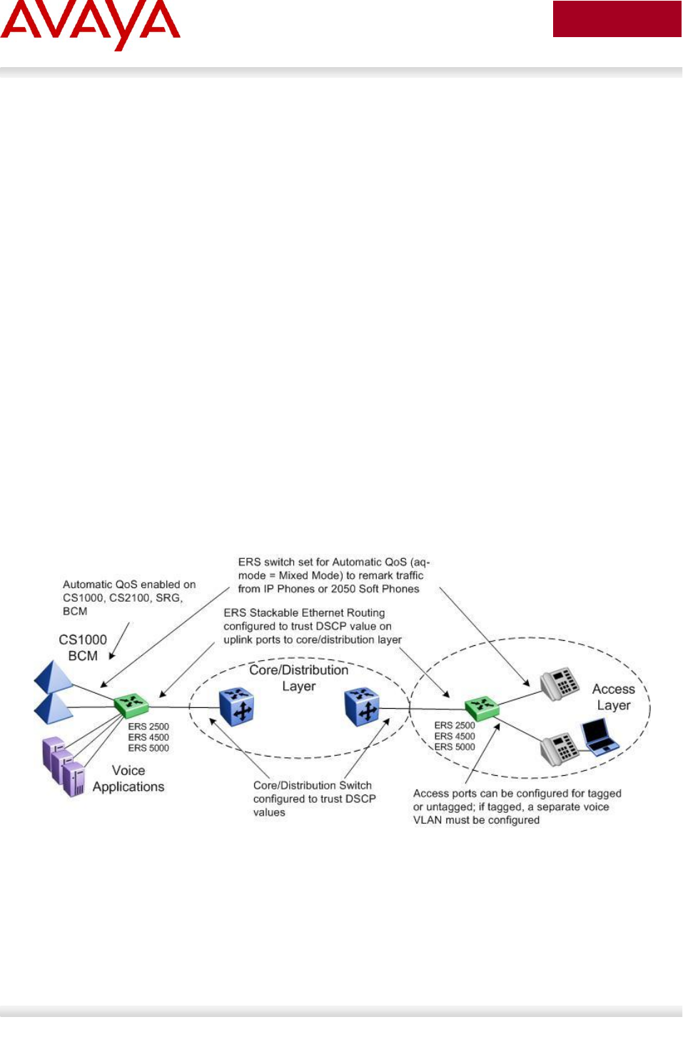
Avaya Inc. – External Distribution
226
avaya.com
Aug 2012
8.5 Automatic QoS
Automatic QoS provides application traffic prioritization allowing for the ability to identify and prioritize
Avaya application traffic. This applies to both an Avaya only or Avaya edge and third party core data
infrastructure to provide application aware networking. Avaya application traffic is defined as IP
Telephony and Multimedia applications. By identifying Avaya application traffic, Automatic QoS
transparently provides appropriate traffic prioritization handling and in turn improves application
performance particularly in times of network congestion. Automatic QoS is applied end-to-end from the
application traffic to the Avaya or third party data infrastructure without the need to configure individual
application filters and QoS components across a variety of platforms. Simply enable/disable the
appropriate Automatic QoS mode and all underlying QoS configurations to identify Avaya application
traffic are automatically configured. Well known Avaya application traffic that is automatically identified via
DSCP values will be given preferential treatment and will be handled by the appropriate egress queue on
the Ethernet switching infrastructure.
As shown in the diagram below, dynamic prioritization is provided by enabling Automatic QoS on the
Stackable Ethernet Routing Switch edge access switch and on the CS1000, CS2100, BCM, and/or SRG
call servers. In regards to the edge switch, the Stackable Ethernet Routing Switch supports dynamic
prioritization for either tagged or untagged IP telephony traffic. The only other configuration required on
the edge switch is setting the uplink port members attached to the core/distribution layer as trusted port
members. In the core, all that is required is enabling the port members as QoS trusted.
Please note that Automatic QoS configuration is only available using the CS1000,
CS2100, BCM, and/or SRG call servers.
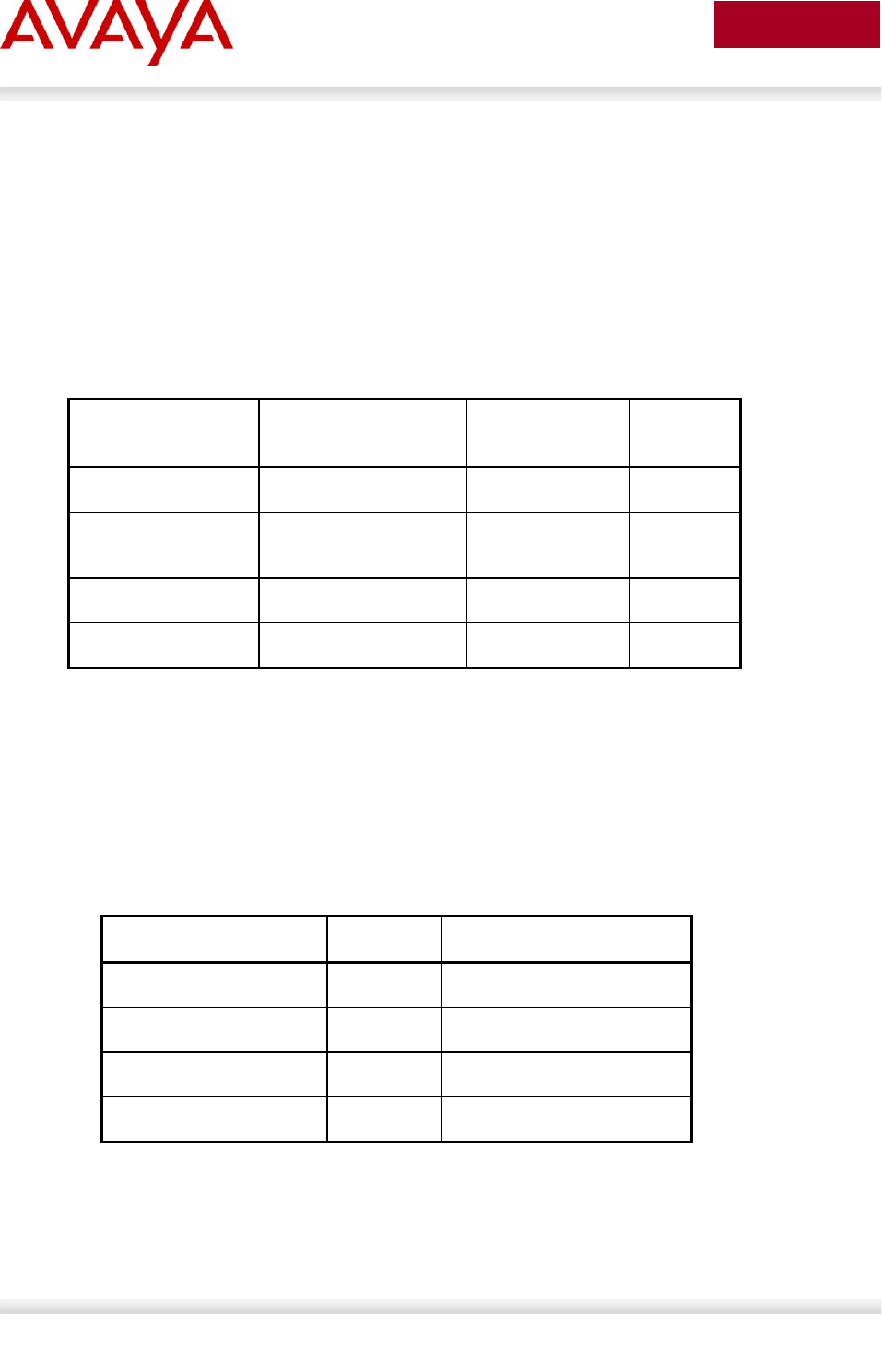
Avaya Inc. – External Distribution
227
avaya.com
Aug 2012
8.5.1 Automatic QoS Edge Mode: Stackable Ethernet
Routing Switch
On the Stackable Ethernet Routing Switch, when enabling dynamic prioritization via Automatic QoS
Edge, there are two modes to choose from, mixed mode and pure mode.
In mixed mode, the Stackable Ethernet Routing Switch will recognize and remark the traffic from the
attached IP phone, IP Softphone 2050 client or BCM/SRG/CS1000/CS2100 according to values shown in
Table 27. As long as the switches used in the core/distribution layer are configured as QoS trusted, these
remarked DSCP values will be given preferential treatment and will be handled by the appropriate egress
queue.
NT DSCP from IP
Phone
Traffic Type
Standard DSCP
Standard
p-bit
0x2F (47)
VoIP Data (Premium)
0x2E (46) (EF)
6
0x29 (41)
VoIP Signaling
(Platinum)
0x28 (40) (CS5)
5
0x23 (35)
Video (Platinum)
0x22 (34) (AF41)
5
0x1B (27)
Streaming (Gold)
0x1A (26) (AF31)
4
Table 27: NT DSCP Mapping Values (Mixed)
Please note that all other traffic types not identified will be handled as normal
unidentified traffic and will be remarked as “Standard/Best Effort” with DSCP value of
0x00 and treated as untrusted traffic.
In pure mode, the Stackable Ethernet Routing Switch will recognize and not remark the traffic from the
attached IP phone, IP Softphone 2050 client or BCM/SRG/CS1000/CS2100. Avaya DSCP values will be
given preferential treatment and will be handled by the appropriate egress queue and the packet will
retain these DSCP values as shown in Table 28.
NT DSCP
NT p-bit
Traffic Type
0x2F (47)
6
VoIP Data (Premium)
0x29 (41)
5
VoIP Signaling (Platinum)
0x23 (35)
5
Video (Platinum)
0x1B (27)
4
Streaming (Gold)
Table 28: NT DSCP Values (Pure)

Avaya Inc. – External Distribution
228
avaya.com
Aug 2012
Please note that all other traffic types not identified will be handled as normal
unidentified traffic and will be remarked as “Standard/Best Effort” with DSCP value of
0x00 and treated as untrusted traffic.
Automatic QoS support is envisioned as a multi-phase project. In phase 1 of Automatic QoS, ADAC,
NSNA, Automatic QoS pure mode, or 802.1AB is not supported simultaneously. This will be added in
subsequent phases of Automatic QoS.

Avaya Inc. – External Distribution
229
avaya.com
Aug 2012
8.5.2 Automatic QoS Configuration – Stackable Ethernet
Routing Switch
Automatic QoS is configured by using the following command:
ERS-Stackable(config)#qos agent aq-mode ?
disable Auto QOS application traffic processing disabled on all ports
mixed Auto QOS application traffic processing enabled on all ports with
egress DSCP remapping
pure Auto QOS application traffic processing enabled on all ports without
egress DSCP remapping
where:
Parameter
Description
disable
Disables Automatic QoS functionality for the system
mixed
Enables Automatic QoS functionality with DSCP remarking at egress
enabled. Private Avaya DSCP values will be remarked to corresponding
standard DSCP values.
pure
Enables Automatic QoS functionality with DSCP remarking at egress
disabled. Private DSCP values will be honored while all other traffic is
remarked to QoS level of Standard. Please note that this mode is not
supported at this time.
Please note that phase 1 of Automatic QoS does not support ADAC, NSNA, or 802.1AB
simultaneously. Depending on the software release, the ACLI Automatic QOS
command may either be qos agent aq-mode or qos agent nt-mode.
8.5.2.1 Core Ports
Although not necessary, the core or uplink port members could be configured as QoS trusted ports if you
wish to trust all QoS levels besides just the Automatic QoS levels. This can be accomplished by first
adding a new QoS interface group and then adding the port members to this interface group.
ERS-Stackable(config)#qos if-group name <if-group_name> class trusted
ERS-Stackable(config)#qos if-assign port <port members> name <if-group_name>
Avaya Inc. – External Distribution
230
avaya.com
Aug 2012
8.6 Configuring QoS on a Avaya Switch for Voice
Traffic
8.6.1 Stackable Ethernet Routing Switch - Creating a new
Interface Group of Trusted
The following will show how to use a Policy, ACL, or Traffic profile to only trust the voice traffic assuming
we will use VLAN 220 for the voice VLAN and 1000 for the data VLAN
Section 7.6.1: Creating a new Interface Group with a class of trusted
o Remark the data VLAN to CoS level of Standard or best effort by adding either a QoS
policy, an ACL, or Traffic Profile
Section 7.6.2: Using the default Interface Group with a class of untrusted
o Remarking the voice VLAN to CoS level of Premium by adding either a QoS policy, an
ACL, or Traffic Profile
8.6.1.1 Stackable Ethernet Routing Switch - Using a Policy
ERS Stackable: Step 1 – Add a new interface group with a class of trusted and add port
members. For this example, we will name the if-group “trusted”.
ERS-Stackable(config)#qos if-group name trusted class trusted
ERS-Stackable(config)#qos if-assign port 1-24 name trusted
ERS Stackable: Step 2 – Create two elements, one matching the voice VLAN and another
matching the data VLAN and set the EtherType to 0x0800. An EtherType value of 0x0800
signifies IP traffic
ERS-Stackable(config)#qos l2-element 1 vlan-min 220 vlan-max 220 ethertype
0x800
ERS-Stackable(config)#qos l2-element 2 vlan-min 1000 vlan-max 1000 ethertype
0x800
ERS Stackable: Step 3 – Add each layer 2 element to a classifier by starting with classifier
id 1 and adding the layer 2 element id’s from step above
ERS-Stackable(config)#qos classifier 1 set-id 1 name voice element-type l2
element-id 1
ERS-Stackable(config)#qos classifier 2 set-id 2 name data element-type l2
element-id 2

Avaya Inc. – External Distribution
231
avaya.com
Aug 2012
ERS Stackable: Step 3 – Create a classifier-block and add both classifiers from the
previous step to it. For the voice classifier, we will add an in-profile action of null to pass
all voice traffic as-is. For the data classifier, we will add an in-profile action of standard to
remark all the traffic to a QoS level of standard. Please note that a classifier block can be
used in this example because both of the classifier elements are of the same type, i.e.
both are a layer 2 element matching a VLAN with the same EtherType.
ERS-Stackable(config)#qos classifier-block 1 block-number 1 name data_remark
set-id 1 in-profile-action 9
ERS-Stackable(config)#qos classifier-block 2 block-number 1 name data_remark
set-id 2 in-profile-action 2
ERS Stackable: Step 4 – Add a policy, for this example named VoIP_Policy, add classifier-
block id 1 configured above, and set the precedence to a value from 1 to 7 for the ERS
4000, 2 to 11 for the ERS 2500, and 1 to 15 for the ERS 5000.
ERS-Stackable(config)#qos policy 1 name "VoIP_Policy" if-group trusted clfr-
type block clfr-name data_remark precedence 3
Note that you can use either ID’s or names for the classifiers and policy actions.
To understand what the in-profile-action and non-match-action refer to, enter the
following command:
ERS-Stackable#show qos action 2
ERS-Stackable#show qos action 9
Id: 2
Name: Standard_Service
Drop: No
Update DSCP: 0x0
802.1p Priority: Priority 0
Set Drop Precedence: High Drop
Extension:
Session Id: 0
Storage Type: ReadOnly
Id: 9
Name: Null_Action
Drop: No
Update DSCP: Ignore
802.1p Priority: Ignore
Set Drop Precedence: Low Drop
Extension:
Session Id: 0
Storage Type: ReadOnly

Avaya Inc. – External Distribution
232
avaya.com
Aug 2012
8.6.1.2 Stackable Ethernet Routing Switch – using an ACL
ERS Stackable: Step 1 – Add a new interface group with a class of trusted and add port
members. For this example, we will name the if-group “trusted”.
ERS-Stackable(config)#qos if-group name trusted class trusted
ERS-Stackable(config)#qos if-assign port 1-24 name trusted
ERS Stackable: Step 1 – Create the ACL to match the data VLAN and remark DSCP and p-
bit values to 0. Please note the default action of an ACL is drop for all other traffic not
matched by an ACL, hence, we also need to add a drop-action of disable to our ACL:
ERS-Stackable(config)#qos l2-acl name one vlan-min 1000 vlan-max 1000 ethertype
0x800 drop-action disable update-dscp 0 update-1p 0
ERS-Stackable(config)#qos l2-acl name one ethertype 0x800 drop-action disable
ERS Stackable: Step 2 – Assign the ACL vlan_fil to the appropriate port members
ERS-Stackable(config)#qos acl-assign port 1-24 acl-type l2 name one
To view the configuration, enter the following commands”
ERS-Stackable#show qos l2-acl
ERS-Stackable#show qos acl-assign
To remove the configuration, enter the following commands:
ERS-Stackable#no qos acl-assign x (where x = id assigned to port; in our
case, this command has to be repeated 24 times where x = 1 to 24 as we
assigned the ACL to 24 port members)
ERS-Stackable#no qos l2-acl 1
ERS-Stackable#no qos l2-acl 2
ERS-Stackable#no qos l2-acl all (remove all L2-ACL’s)

Avaya Inc. – External Distribution
233
avaya.com
Aug 2012
8.6.1.3 Stackable Ethernet Routing Switch – using an Traffic Profile
Please note Traffic Profiles can only be applied to the ERS 4000 and ERS 5000.
ERS Stackable: Step 1 – Add a new interface group with a class of trusted and add port
members. For this example, we will name the if-group “trusted”.
ERS-Stackable(config)#qos if-group name trusted class trusted
ERS-Stackable(config)#qos if-assign port 1-24 name trusted
ERS Stackable: Step 2 – Create the traffic profile to match the data VLAN and remark
DSCP and p-bit values to 0
ERS-Stackable(config)#qos traffic-profile classifier name one vlan-min 1000
vlan-max 1000 ethertype 0x800 update-dscp 0 update-1p 0
ERS Stackable: Step 2 – Assign the traffic profile one to the appropriate port members
ERS-Stackable(config)#qos traffic-profile set port 1-24 name one
At mimimum, software release 6.1 for the ERS 5000 and 5.4 for the ERS 4000 must be
used in order to create traffic profiles.
Avaya Inc. – External Distribution
234
avaya.com
Aug 2012
8.6.2 Stackable Ethernet Routing Switch - Assuming default
role combination with class of untrusted
By default, all ports belong to the default interface group named allQoSPolicyIfcs with an interface class
of untrusted. Hence, it is not nessessary to create a new interface group.
8.6.2.1 Stackable Ethernet Routing Switch – using an Policy
ERS Stackable: Step 1 – Create a new layer 2 element, assign Voice VLAN and set the
EtherType to 0x0800
ERS-Stackable(config)#qos l2-element 1 vlan-min 220 vlan-max 220 ethertype
0x800
ERS Stackable: Step 2 – Add layer 2 element to a classifier by starting with classifier id 1
and adding layer 2 element id 1 from step above
ERS-Stackable(config)#qos classifier 1 set-id 1 name VoIP_Class element-type l2
element-id 1
ERS Stackable: Step 3 – Add a policy, for this example named VoIP_Policy, add classifier
id 1 configured above, set in-profile-action to remark to Premium CoS, and set the non-
match action to remark to Standard CoS.
ERS-Stackable(config)#qos policy 1 name VoIP_Policy if-group allQoSPolicyIfcs
clfr-type classifier clfr-id 1 in-profile-action 7 non-match-action 2
ERS Stackable: Step 3 – Add a policy, for this example named VoIP_Policy, add classifier
id 1 configured above, set in-profile-action to remark to Premium CoS, and set the non-
match action to remark to Standard CoS.
ERS-Stackable(config)#qos policy 1 name "VoIP_Policy" if-group allQoSPolicyIfcs
clfr-type classifier clfr-id 1 in-profile-action 7 precedence 3
You can also apply the policy to an individual port member instead of an interface role
with multiple port members. For example, assuming only wish to apply the policy to port
12, enter the following command:
ERS-Stackable(config)#qos policy 1 name VoIP_Policy port 12 clfr-type
classifier clfr-id 1 in-profile-action 7 non-match-action 2

Avaya Inc. – External Distribution
235
avaya.com
Aug 2012
8.6.2.2 Stackable Ethernet Routing Switch – using an ACL
ERS Stackable: Step 1 – Create an ACL to match the voice VLAN. Please note that default
action of an ACL is drop for all other traffic not matched by an ACL, hence, we also need
to add a drop-action of disable to our ACL:
ERS-Stackable(config)#qos l2-acl name one vlan-min 220 vlan-max 220 ethertype
0x800 update-dscp 46 update-1p 6
ERS-Stackable(config)#qos l2-acl name one ethertype 0x800 drop-action disable
ERS Stackable: Step 2 – Assign the ACL to the appropriate port members; for example,
port member 1-24:
ERS-Stackable(config)#qos acl-assign port 1-24 acl-type l2 name one
8.6.2.3 Stackable Ethernet Routing Switch – using a Traffic Profile
Please note Traffic Profiles can only be applied to the ERS 4000 and ERS 5000.
ERS Stackable: Step 1 – Create the traffic profile to match the voice VLAN and remark
DSCP and p-bit values
ERS-Stackable(config)#qos traffic-profile classifier name one vlan-min 220
vlan-max 220 ethertype 0x800 update-dscp 46 update-1p 6
ERS Stackable: Step 2 – Assign the traffic profile one to the appropriate port members
ERS-Stackable(config)#qos traffic-profile set port 1-24 name one
At mimimum, software release 6.1 for the ERS 5000 and 5.4 for the ERS 4000 must be
used in order to create traffic profiles.

Avaya Inc. – External Distribution
236
avaya.com
Aug 2012
8.6.3 Configure L2 QoS on a Ethernet Routing Switch 8300
By default, the Ethernet Routing Switch 8300 trusts the 802.1p value with a default behavior as shown in
table 29 below. Providing the VoIP VLAN is tagged, no additional configuration steps are required.
Traffic Type
802.1p
DSCP
Behavior
Queue
Behavior
Queue
Bridged, i.e. VLAN without IP address
Tagged
Passed as-is
As per traffic
class and
queue mapping
Passed as-is
As per p-bit
Untagged
N/A
N/A
Passed as-is
Queue 1
Routed, i.e. VLAN with IP address assigned
Tagged
Passed as-is
As per traffic
class and
queue mapping
Passed as-is
As per p-bit
Untagged
N/A
N/A
Passed as-is
Queue 1
Table 29: Default QOS Behavior for the Ethernet Routing Switch 8300
If the IP Phone set voice VLAN is not tagged or if the voice VLAN is tagged and you wish to trust the
DSCP value instead of the p-bit, you could set up a filter to trust the DSCP value. You can also classify
traffic based on VLAN value or filters.
8.6.3.1 Trust DSCP Value Configuration
To setup a filter to trust the DSCP value, please enter the following commands.
ERS8300: Step 1 – Create a new ACL with an action to trust the DSCP value. Assuming no
ACLs have been configured, start with ACL 1
CLI
ERS8300:5# config filter acl 1 create ip
ERS8300:5# config filter acl 1 ace 1 action permit trust-dscp enable
ACLI
ERS8300:5(config)#filter acl 1 ip
ERS8300:5(config)#filter acl 1 action 1 permit trust-dscp enable
ERS8300: Step 2 – Create an ACG group and add ACL configured in step 1 above.
Assuming no ACG have been configured, start with ACG 1
CLI
ERS8300:5# config filter acg 1 create 1

Avaya Inc. – External Distribution
237
avaya.com
Aug 2012
ACLI
ERS8300:5(config)#filter acg 1 1
ERS8300: Step 3 – Add the ACG created in step 2 to all appropriate port members
CLI
ERS8300:5# config ethernet <port #> filter create 1
ACLI
ERS8300:5(config)#interface fastEthernet <slot/port>
ERS8300:5(config-if)#filter 1
ERS8300:5(config-if)#exit
You can enable or disable trusted DSCP at an interface level as per the configuration steps shown below.
ERS8300: Step 1 – Enable trust-dscp via interface level
CLI
ERS8300:5# config ethernet <slot/port> qos trust-dscp enable
ACLI
ERS8300:5(config)# interface gigabitEthernet <slot/port>
ERS8300:5(config-if)#qos trust-dscp enable
ERS8300:5(config-if)#exit

Avaya Inc. – External Distribution
238
avaya.com
Aug 2012
8.6.3.2 Classify traffic based on VLAN basis
For IP subnet and Protocol-based VLANs you can set up a default traffic class level based on the VLAN
id. The VLAN QoS level can be assigned a value from 0 (lowest) to 7 (highest) with a default setting of 1.
Note that you cannot apply a VLAN QoS level to port-based VLANs. For example, assuming the VoIP
VLAN is 220 with port members 1/3 to 1/11, enter the following commands:
ERS8300: Step 1 – Create VLAN 220 and add port members
CLI
ERS8300:5# config vlan 220 create byprotocol 1 ip
ERS8300:5# config vlan 1 ports remove 1/1-1/11
ERS8300:5# config vlan 220 ports add 1/1-1/11
ACLI
ERS8300:5(config)#vlan create 220 type protocol-ipether2 1
ERS8300:5(config)#vlan members remove 1 1/1-1/11
ERS8300:5(config)#vlan members add 220 1/1-1/11
ERS8300: Step 2 – Assign QoS level
CLI
ERS8300:5# config vlan 220 qos-level 6
ACLI
ERS8300:5(config)#vlan qos-level 220 6
ERS8300: Step 3 – Enable Dynamic MAC QoS Update
CLI
ERS8300:5# config vlan 220 update-dynamic-mac-qos-level enable
ACLI
ERS8300:5(config)#vlan update-dynamic-mac-qos-level 220
The dynamic update parameter is used to enable to disable the update of the MAC
traffic class assignment when the VLAN traffic class changes.
Avaya Inc. – External Distribution
239
avaya.com
Aug 2012
8.6.3.3 Classify traffic based on a filter
Assuming we wish to filter on the VoIP VLAN with the MAC address range belonging to the IP Phone sets
and set the DiffServ value to EF (0x2e). This can be accomplished by using the commands shown below.
For our example, we will assume the voice VLAN is 220 while the MAC address range is from
00:0a:e4:00:00:00 to 00:0a:e4:ff:ff:ff.
ERS8300: Step 1 – Create a new ACT to allow ACL filtering on MAC addresses
CLI
ERS8300:5# filter act 2 ethernet ip src-mac ff:ff:ff:ff:ff:ff dst-mac
ff:ff:ff:ff:ff:ff vlan-mask 0x0fff name "act_2_ip-mac"
ACLI
ERS8300:5(config)#filter act 2 ethernet ip src-mask ff:ff:ff:ff:ff:ff dst-mask
ff:ff:ff:ff:ff:ff vlan-mask 0x0fff name act-2-ip-mac
ERS8300: Step 2 – Enable the ACT to also allow ACL filtering on the DSCP value
CLI
ERS8300:5# config filter act 2 ip 0.0.0.0 tos 0xff
ACLI
ERS8300:5(config)#filter act 2 ip tos 0xff
ERS8300: Step 3 – Add ACL 1 using the name ACL-1_VoIP, add ACT 2 created above, and
enable the ACL to filter on the specified MAC address in VLAN 220 to remark traffic using
Premium CoS and remark all other traffic as Standard CoS
CLI
ERS8300:5# config filter acl 1 create ip acl-name ACL-1_VoIP act-id 2
ERS8300:5# config filter acl 1 ace 1 action permit remark-dscp phbef "ACE-
1_remark" precedence 1
ERS8300:5# config filter acl 1 ace 1 ethernet src-mac 00:0a:e4:00:00:00 range
00:0a:e4:ff:ff:ff vlan-id 220
ERS8300:5# config filter acl 1 ace default action permit remark-dscp phbcs0
ACLI
ERS8300:5(config)#filter acl 1 ip acl-name ACL-1_VoIP act-id 2
ERS8300:5(config)# filter acl 1 action 1 permit remark-dscp phbef ACE-1_remark
precedence 1
ERS8300:5(config)#filter acl 1 ethernet 1 src-mac 00:0a:e4:00:00:00 range
00:0a:e4:ff:ff:ff vlan-id 220
ERS8300:5(config)#filter acl 1 action default permit remark-dscp phbcs0
ERS8300: Step 4 – Create a new ACT to allow ACL filtering on MAC addresses. For this
example, we will name the ACG ACG-1_Voip.
CLI

Avaya Inc. – External Distribution
240
avaya.com
Aug 2012
ERS8300:5# config filter acg 1 create 1 acg-name ACG-1_Voip
ACLI
ERS8300:5(config)#filter acg 1 1 acg-name ACG-1_Voip
ERS8300: Step 5 – Add ACG ‘ACG-1_Voip’ to interface level and disable p-bit override.
CLI
ERS8300:5# config ethernet <slot/port> filter create 1
ERS8300:5# config ethernet <slot/port> qos 8021p-override enable
ACLI
ERS8300:5(config)#interface fastEthernet <slot/port>
ERS8300:5(config-if)#filter 1
ERS8300:5(config-if)#qos 8021p-override
ERS8300:5(config-if)#exit

Avaya Inc. – External Distribution
241
avaya.com
Aug 2012
8.6.3.4 Verify QoS Operation using IPFIX
IPFIX can be used to verify the DSCP settings. For example, assuming if we are using an ERS 8000 in
the core where the edge switch is connected to port 3/29, entering the following commands on the ERS
8000 allows to verify the DSCP on values send from the traffic ingressing this port.
ERS8000: Step 1 – Enable IPFIX globally
ERS8000:5# config ip ipfix state enable
ERS8000: Step 2 – Enable IPFIX at interface level, assuming port 3/29 for this example
ERS8000:5# config ip ipfix port 3/29 all-traffic enable
ERS8000: Step 3 – Verify DSCP values via slot 3, assuming we have VoIP traffic via VLAN
805
ERS8000:5# show ip ipfix flows 3
Results:
================================================================================
IPFIX Flows
================================================================================
Slot Number : 3 Total Number Of Flows : 3
Port/ SrcIP/DstIP Src/ Protcol/ DSCP/ Egrss Start/Last
Vlan Addr Dst Obsv TcpFlag Port/ Time
Port Point Mgid
--------------------------------------------------------------------------------
3/29 10.5.85.10 5201 udp 184 3/27 AUG 1 11:38:35
805 10.5.83.10 51009 Port none AUG 1 11:38:35
3/29 10.5.85.10 5200 udp 184 3/27 AUG 1 11:38:32
805 10.5.83.10 51008 Port none AUG 13 11:38:36
3/29 10.5.85.10 5000 udp 184 3/3 AUG 1 11:38:21
805 10.88.2.10 5100 Port none AUG 1 11:38:36
Total number of Displayed Flows on Slot 3 : 3
--------------------------------------------------------------------------------
Port/ SrcMac/DstMac Byte/Pkt
Vlan Count
--------------------------------------------------------------------------------

Avaya Inc. – External Distribution
242
avaya.com
Aug 2012
3/29 00:24:00:0d:8d:aa 114
805 00:00:5e:00:01:55 1
3/29 00:24:00:0d:8d:aa 918636
805 00:00:5e:00:01:55 4138
3/29 00:24:00:0d:8d:aa 92670
805 00:00:5e:00:01:55 1440
Please note the DSCP value shown is actually the ToS value. To calculate the DSCP
value, drop the two least significant binary bits. For this example, 184 in binary is
“10111000” where the two least significant bits become binary “101110” or decimal 46.

Avaya Inc. – External Distribution
243
avaya.com
Aug 2012
9. Anti-Spoofing Best Practices
Overview – ARP Poison
ARP spoofing simply involves spoofing an IP address of a victim thereby allowing frames destined for the
remote host to be forwarded to the attacker. For example, by sending Gratuitous ARP (GARP) frames
between an attacker to a victim and a default gateway router within a VLAN of a Layer 2 switch, a man-in-
the-middle (MITM) attack can occur.
Overview – IP Spoofing
IP spoofing refers to the creation of IP packets with a spoofed source IP address other than the local
network address. By forging the source IP address, an attacker can make the packet appear as it was
sent by a different machine. The victim that receives the spoofed packets will send responses back to the
forged source address.
IP Source Guard
IP Source Guard provides security to the network by filtering clients with invalid IP addresses. IPSource
Guard works closely with information in the Dynamic Host Control Protocol (DHCP) snooping binding
table. When IP Source Guard is enabled on an untrusted port with DHCP snooping enabled, an IP filter
entry is created or deleted for that port automatically, based on IP information stored in the corresponding
DHCP snooping binding table entry. When a connecting client receives a valid IP address from the DHCP
server, a filter is installed on the port to allow traffic only from the assigned IP address. A maximum of 10
IP addresses are allowed on each IP Source Guard-enabled port. When this number is reached, no more
filters are set up and traffic is dropped. When IP Source Guard is enabled without DHCP snooping
enabled, a default filter is installed and IP traffic for the port is dropped.
Defense against Spoofing
Avaya IP Phone sets supports GARP feature – please see section 3. However, this feature only prevents
ARP spoofing one way from the IP Phone set to the default gateway address. Therefore, if the voice call
is to another phone set that is off-net (to a phone on a different subnet or switch) an attacker can only
poison the phone one-way. The attacker can only record the voice traffic from a remote phone sent to the
local phone set and not from the local phone to the remote phone. The IP Phone GARP also does
prevent an on-net attack. On-net refers to the same VLAN on a switch where both IP phone are
connected.
To prevent ARP Spoofing, it is recommended to enabled DHCP Snooping and ARP Spoofing when
available on the local switch where the IP Phone sets are connected. Both of these mechanisms will
prevent Man-in-the-middle (MITM) attacks and spoofing a victims IP address. In addition, it is also
recommended to enable IP Spoofing either on the local switch where the IP Phone sets are attached or in
the core.

Avaya Inc. – External Distribution
244
avaya.com
Aug 2012
Summary Chart
The following chart provides a summary of Off-Net and On-Net MITM attacks.
An ‘X” indicated MITM attack (ARP Spoofing can occur) in both directions, i.e. the ability to
capture traffic from a local phone set to the remote phone set and vise-versa.
An “” indicates a MITM attack does not occur
An “” indicates a one-way MITM attack from an remote phone set to the local phone set only
Off-Net indicates traffic off the local subnet
On-Net indicated traffic between two devices within the same VLAN, i.e. same subnet, on a local
switch
Switch
Traffic Type
Off-Net
On-Net
Generic L2 switch
Data
X
X
Voice
X
X
Voice with GARP
disabled on IP Phone
X
X
Voice with GARP
enabled on IP Phone
ERS switch with ARP
Spoofing Prevention
enabled
Data
Voice
Voice with GARP
enabled on IP Phone
Table 30: MITM Attacks

Avaya Inc. – External Distribution
245
avaya.com
Aug 2012
Support on Avaya Switches
Switch
Feature
DHCP Snooping
ARP Inspection
IP Source Guard
ERS2500
(4.2)
(4.2)
(4.2)
ERS3500
(5.0)
(5.0)
(5.0)
ERS5500
(5.0)
(5.0)
(5.1)
ERS5600
(6.0)
(6.0)
(6.0)
ERS4000
(5.1)
(5.1)
(5.2)
ERS8300
(4.2)
(4.2)
(4.2)
Core
ERS8600
(7.0)
(7.0)
(4.1)*
*Requires software release 4.1 with R-modules (does not require R-mode)
Table 31: Anti-Spoofing support on Avaya Switches
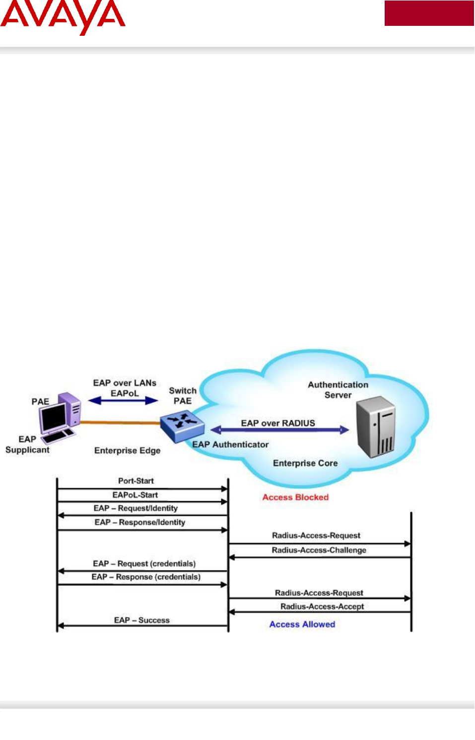
Avaya Inc. – External Distribution
246
avaya.com
Aug 2012
10. EAPoL Support
10.1 EAP Overview
Extensible Authentication Protocol over LAN is a port-based network access control protocol. EAPoL
provides a method for performing authentication at the edge of the network in order to obtain network
access based on the IEEE 802.1X standard.
802.1X specifies a protocol used between devices (EAP Supplicants) that desire access to the network
and devices providing access to the network (EAP Authenticator). It also specifies the requirements for
the protocol used between the EAP Authenticator and the Authentication server, i.e. RADIUS. The
following are some of the 802.1X definitions:
Authenticator: The entity that requires the entity on the other end of the link to be authenticated.
Authenticator passes authentication exchanges between supplicant and authentication server.
Supplicant: The entity being authenticated by the Authenticator and desiring access to the
services of the Authenticator.
Port Access Entity (PAE): The protocol entity associated with a port. May support functionality of
Authenticator, Supplicant or both.
Authentication Server: An entity providing authentication service to the Authenticator. May be co-
located with Authenticator, but most likely an external server.
Figure 18: EAP Overview
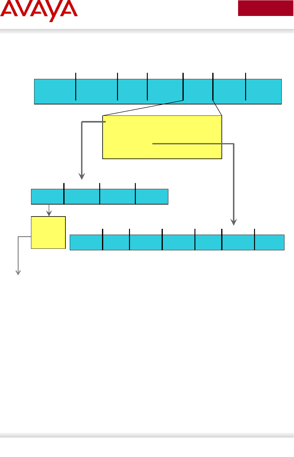
Avaya Inc. – External Distribution
247
avaya.com
Aug 2012
802.1x Ethernet Frame
Figure 19: EAP Frame
EAP Request and Response Code Types
Type code 1: Identity
Type code 2: Notification
Type code 3: NAK
Type code 4: MD-5 Challenge
Type code 5: One-time password (OTP)
Type code 6: Generic Token Card
Type code 13: TLS
EAP and RADIUS related RFCs
RFC2284 – PPP Extensible Authentication Protocol
RFC2716 – PPP EAP Transport Level Security (TLS) Authentication Protocol
RFC2865 (Obsoletes RFC2138) – RADIUS
RFC2548 – Microsoft Vendor specific RADIUS Attributes
Dest. MAC
0180C200000x
Type
88-8E
Protocol
Version
Packet
Type
6 bytes
6 bytes
2 bytes
1 byte
Source
MAC
1 byte
Packet
Body
Length
2 bytes
Packet
Body
n bytes
00 EAP-Packet
01 EAPOL-Start *
02 EAPOL-Logoff *
03 EAPOL-Key
04 EAPOL-Encapsulated-ASF-Alert
Code
Identifier
Length
Data
1 byte
1 byte
2 bytes
n bytes
Descriptor
Type
Key
Length
Relay
Counter
Key IV
1 byte
2 bytes
8 bytes
16 bytes
Key
Index
Key
Signature
Key
1 byte
n bytes
16 bytes
* No packet
body field
Packet body field
Packet body field
1 Request
2 Response
3 Success
4 Failure

Avaya Inc. – External Distribution
248
avaya.com
Aug 2012
10.2 EAP Support on Avaya IP Phone Sets
The following table shows the authentication methods supported on each type of Avaya IP phone.
Authentication
method
IP Phone
EAP MD5
IP Phone 2001, IP Phone 2002, IP Phone 2004, IP Audio
Conference Phone 2033, IP Phone 1210, IP Phone 1220, IP
Phone 1230, IP Phone 2007, IP Phone 1110, IP Phone 1120E,
IP Phone 1140E, and IP Phone 1150E.
Beginning with 46xx H.323 Release 2.6, 96xx H.323 Release
1.0, 96xx SIP Release 2.0, and 16xx H.323 Release 1.0.
EAP PEAP, EAP TLS
IP Phone 1210, IP Phone 1220, IP Phone 1230, IP Phone 2007,
IP Phone 1110, IP Phone 1120E, IP Phone 1140E, and IP
Phone 1150E
The 96xx SIP Supplicant supports EAP-TLS authentication
Table 32: EAP Support on Avaya IP Phones

Avaya Inc. – External Distribution
249
avaya.com
Aug 2012
10.3 EAP and ADAC
ADAC and EAP are mutually exclusive on
The Call Server port
The Uplink port
ADAC and EAP can both be enabled on telephony ports as follows:
The ports must be configured to allow non-EAP MAC addresses
Guest VLAN must not be configured on the ports
o In software release 5.0 for the ERS 3500, 5.6 for the ERS 4000 and 5.6 for the ERS 5000
it is now possible to support Guest VLAN and fail-open VLAN providing the vlan voice-
vlan & eapol multihost voip parameters are configured
To enable ADAC on an EAP port, you must perform the following:
On the switch, globally enable support for non-EAP MAC addresses
On each telephony port, enable support for non-EAP MAC addresses
On each telephony port, enable EAP Multihost
On the telephony ports, ensure that Guest VLAN is disabled
o This does not apply to software release 5.6 for the ERS 4000 and 5.6 for the ERS 5000
On the switch, enable EAP globally
Configure and enable ADAC on the ports
When you configure ADAC and EAP, the following restrictions apply:
If ADAC is enabled, you cannot enable or disable EAP or EAP Multihost on the port
You can enable ADAC on the port only if:
EAP is disabled on the port OR EAP and Multihost are enabled on the port
EAP does not change the VLAN configuration for ADAC-enabled ports. ADAC changes to the
VLAN configuration take priority over EAP configurations
o Note, these restrictions no longer apply to the ERS 3500, software release 5.6 for the
ERS 4000 and 5.6 for the ERS 5000

Avaya Inc. – External Distribution
250
avaya.com
Aug 2012
10.4 EAP Support on Avaya Switches
Table 33 shown below display’s the various EAP features supported on the Avaya switches used for this
TCG.
Authentication Feature
Switch
Ethernet
Routing
Switch
2500
Ethernet
Routing
Switch
3500
Ethernet
Routing
Switch
4000
Ethernet
Routing
Switch
5500
Ethernet
Routing
Switch
5600
Ethernet
Routing
Switch
8300
Single Host Single
Authentication (SHSA)
Yes
Yes
Yes
Yes
Yes
Yes
Multiple Host Single
Authentication (MHSA)
Yes
Yes
Yes
Yes
Yes
Yes
Multiple Host Multiple
Authentication (MHMA)
Yes
Yes
Yes
Yes
Yes
Yes
MHMA MultiVLAN – EAP
and non-EAP
No
No
Yes (5.4)
Yes (6.2)
Yes (6.2)
No
*Guest VLAN with EAP
(GVLAN-SHSA)
Yes (4.1.0)
Yes
Yes
Yes (5.0.0)
Yes
Yes
SHSA with Guest VLAN
Yes
Yes
Yes
Yes
Yes
Yes
*MHSA with Guest VLAN
Yes (4.1.0)
Yes
Yes (5.1.0)
Yes (5.0.0)
Yes
Yes
MHMA wit Guest VLAN
Yes
Yes
Yes
Yes
Yes
Yes
MAC Based EAP
Authentication
Yes (4.1.0)
Yes
Yes (5.1.0)
Yes (5.0.0)
Yes
Yes
EAP and non-EAP on
same port
Yes
Yes
Yes
Yes
Yes
Yes
RADIUS Assigned VLAN
in MHMA
Yes (4.2.0)
Yes
Yes (5.1.0)
Yes (5.1.0)
Yes
Yes
Non-EAP IP Phone
Support
Yes (4.2.0)
Yes
Yes (5.1.0)
Yes (5.1.0)
Yes
No
EAP or non-EAP with
Guest VLAN
Yes (4.0)
Yes
Yes (5.3.0)
Yes (6.2)
Yes (6.2)
No
EAP or non-EAP with
Fail Open VLAN
Yes (4.4)
Yes
Yes (5.3.0)
Yes (6.2)
Yes (6.2)
No

Avaya Inc. – External Distribution
251
avaya.com
Aug 2012
EAP or non-EAP with
VLAN Name
Yes (4.3)
Yes
Yes (5.3.0)
Yes (6.2)
Yes (6.2)
No
EAP or non-EAP Last
Assigned VLAN
Yes (4.0)
Yes
Yes (5.3.0)
Yes (6.2)
Yes (6.2)
No
Non-EAP use with Wake
on LAN
Yes (4.0)
Yes
Yes (5.3.0)
Yes (6.2)
Yes (6.2)
No
User Based Policy
Support
No
No
No
Yes
Yes
No
Tagged/Untagged
Per VLAN Egress
Tagging
Yes
Yes
Yes
Yes
Yes
Yes
Tagged and untagged
per port
Yes
Yes
Yes
Yes
Yes
Yes
Tagging with EAP
Yes
Yes
Yes
Yes
Yes
**Yes
* Please note that a device is only put into the Guest VLAN providing another user has not already passed EAP
authentication. For example, on a switch port configured for MHMA with Guest VLAN, once an EAP supplicant has
passed EAP authentication, any existing client or any new client that either fails EAP or does not support EAP will be
removed from the Guest VLAN. You cannot enable Guest VLAN and non-EAP on the same port.
1Requires software release 5.1. Not supported for NEAP (centralized MAC authentication)
**The Ethernet Routing Switch 8300 supports tagging with 802.1x in software release 2.2.2.0. Please see software
release notes. Tagging with EAP is not supported in release 2.3, but is reintroduced in release 2.3.1.
Table 33: EAP Support on Avaya Switches

Avaya Inc. – External Distribution
252
avaya.com
Aug 2012
10.5 EAP Feature Overview and Configuration on
Avaya Stackable Switches
10.5.1 Single Host Single Authentication: SHSA
SHSA is the default mode of operation which supports a single EAP Supplicant on a per port basis.
Hence, only one MAC address is allowed per port. If multiple MAC addresses are detected, the port will
be disabled - set to an EAP Force Unauthorized state.
In SHSA mode, the switch supports dynamic VLAN assignment and setting of the port priority via the
RADIUS server.
Once you have setup a RADIUS server, SHSA can be enabled by issuing the following commands.
Global Setting
ERS-Stackable(config)#eapol enable
Interface Level
ERS-Stackable(config)#interface fastEthernet all
ERS-Stackable(config-if)#eapol port <port list> status <authorized | auto | unauthorized>
ERS-Stackable(config-if)#exit
10.5.2 Guest VLAN
By default, if EAP is enabled on a port, an EAP Supplicant is required on the end station and requires
authentication against an Authentication Server. If the end station does not have an EAP Supplicant or if
the EAP authentication fails, the end station can be put into a guest VLAN. Any VLAN can be assigned as
the guest VLAN. The guest VLAN, for example, could allow internet access, but deny access to the
corporate network. A port configured with EAP and Guest VLAN feature only allows one MAC address to
be learned per port. Any traffic from a new host will be discarded.
Global Setting
ERS-Stackable(config)#eapol guest-vlan enable vid <1-4094>
ERS-Stackable(config)#eapol enable
Interface Level
ERS-Stackable(config)#interface fastEthernet all
ERS-Stackable(config-if)#eapol port <port list> status auto
ERS-Stackable(config-if)#eapol guest-vlan port <port list> enable vid <global | <1-4094>
ERS-Stackable(config-if)#exit

Avaya Inc. – External Distribution
253
avaya.com
Aug 2012
10.5.3 Multiple Host Multiple Authentication: MHMA
MHMA allows multiple EAP Supplicants to be authenticated on the same port. Up to eight (8) MACs are
allowed per port for the Ethernet Routing Switch 8300 which can be either EAP Supplicants or non-eap-
mac end stations. Up to 32 MACs are allowed for the ERS 2500, ERS3500, ERS 4000, or ERS 5000. For
non-eap-mac end stations, the MAC address must either be statically configured on the switch or Non-
EAP MAC (NEAP) must be used. If the switch senses more than the configured MHMA limit, traffic from
the new host will be discarded and a trap message is sent.
NOTES: Please be aware of the following when using MHMA:
VLAN Tagging is now supported on a port configuring with MHMA on the Ethernet Routing Switch
8300 in software release 2.2.2.0 and 3.0
As of release 5.4 for the ERS 4000 and 6.2 for the ERS 5000, the maximum number clients
supported is 384 NEAP clients per stack, or 768 EAP clients per stack, or 768 EAP & NEAP
clients per stack. In older repleases, the maximum number of EAP and NEAP clients supported is
384
Global Setting
ERS-Stackable(config)#eapol enable
Interface Level
ERS-Stackable(config)#interface fastEthernet all
ERS-Stackable(config-if)#eapol port <port list> status auto
ERS-Stackable(config-if)# eapol multihost port <port list> enable
ERS-Stackable(config-if)# eapol multihost port <port list> eap-mac-max <1-32>
ERS-Stackable(config-if)#exit
10.5.4 MHMA Radius Assigned VLANs
This feature allows the RADIUS server to dynamically assign VLANs to a port. In MHMA, the switch will
move the port to the VLAN of the first authenticated client and subsequent VLAN assigments are ignored.
MHMA Radius Assigned VLANs can be used with an IP Phone on the port which can be authenticated
via NEAP, IP Phone signature or EAP. Please note if Guest VLAN is enabled, once the IP Phone is
authenticatd, the port is moved out of the Guest VLAN. Please see the MHMA MultiVLAN section below if
you wish to allow multiple VLANs . Please see the MHMA Last Assigned RADIUS VLAN section below if
you wish to allow subsequent VLAN assigments.
Global Setting
ERS-Stackable(config)#eapol multihost use-radius-assigned-vlan
ERS-Stackable(config)#eapol enable
Interface Level
ERS-Stackable(config)#interface fastEthernet all
ERS-Stackable(config-if)#eapol port <port list> status auto
ERS-Stackable(config-if)# eapol multihost port <port list> enable
ERS-Stackable(config-if)#eapol multihost port <port list> use-radius-assigned-vlan
ERS-Stackable(config-if)#exit

Avaya Inc. – External Distribution
254
avaya.com
Aug 2012
10.5.5 MHMA MultiVLAN
EAP MHMA MultiVLAN capability enables a port to support multiple RADIUS assigned VLANs (RAV) per
port. It uses dynamic MAC based VLANs to bind each MAC address dynamically to the appropriate VLAN.
With the EAP MHMA MultiVLAN feature enabled, this will allow EAP to be more widely deployed in
scenarios where end devices are daisy chained from IP Phones. All RAV must be previously defined on
the switch and assigned to uplink ports (as per current configuration requirements).
The IP Phone can be assigned to an appropriate Voice VLAN or RAV and client devices can also be
assigned to RAV based upon their login credentials. An IP Phone on the port can be authenticated via
NEAP, IP Phone signature or EAP and at the same time the port will also maintain Guest VLAN access.
This then allows guest to continue to be able to access the Guest VLAN once the IP Phone is
authenticated. Previously if Guest VLAN were enabled once the IP Phone was authenticated the port was
moved out of the Guest VLAN, meaning you can not have Guest VLAN access once an IP Phone is
authenticated on a port.
Please be aware of the following considerations when using MultiVLAN:
EAP must be globally disabled to enable or disable multiVLAN feature.
RAV must be configured on the switch and uplink ports.
Manually moving a port from a VLAN with authenticated clients is not recommended, EAP should
first be globally disabled.
Deleting a RAV with authenticated clients is not recommended. EAP should first be globally
disabled, so that clients are removed from the VLAN before it is deleted.
Note that each EAP/NEAP client can have only one entry in VLAN_MAC table.
EAP MultiVLAN is mutually exclusive with “RADIUS Last Assigned VLAN” functionality as it
supersedes that functionality as each host will be assigned individual VLANs.
EAP MultiVLAN is mutually exclusive with “Fail Open VLAN”.
If the Guest VLAN is enabled, the port PVID is set to the Guest VLAN, so that all unauthenticated
clients will have access to the Guest VLAN.
If NEAP IP Phone is enabled “non-eap-phone-enable”, then the port will dynamically be a
member of all VoIP VLANs.
Untagged traffic that comes from the authenticated client (identified by its MAC address) will be
placed into the RADIUS Assigned VLAN (RAV) or the initial port VLAN if the RADIUS VLAN
attribute for the client is missing.
If the client sends tagged traffic once authenticated, then if the VLAN is defined for that port, the
traffic will be forwarded for that VLAN.
When a client is physically disconnected, logs-off or is sent an RFC 3576 disconnect message, if
no other clients are assigned to the same RADIUS Assigned VLAN (RAV) on that port, the port
will then be removed from the dynamic VLAN.

Avaya Inc. – External Distribution
255
avaya.com
Aug 2012
Global Setting
ERS-Stackable(config)#eapol multihost use-radius-assigned-vlan
ERS-Stackable(config)#eapol multihost multivlan enable
ERS-Stackable(config)#eapol multihost multivlan voip-vlan <1-5> vid <1-4095>
ERS-Stackable(config)#eapol enable
Interface Level
ERS-Stackable(config)#interface fastEthernet all
ERS-Stackable(config-if)#eapol port <port list> status auto
ERS-Stackable(config-if)#eapol multihost port <port list> use-radius-assigned-vlan
ERS-Stackable(config-if)# eapol multihost port <port list> enable
ERS-Stackable(config-if)#exit
10.5.6 MHMA Last Assigned RADIUS VLAN
This features introduces a mode where the latest RADIUS assigned VLAN will be configured for the port.
Without this feature, the first RADIUS assigned VLAN from the RADIUS server will be used and
subsequent VLAN assignments will be ignored.
Global Setting
ERS-Stackable(config)#eapol multihost use-most-recent-radius-vlan
ERS-Stackable(config)#eapol enable
10.5.7 MHMA with Fail Open VLAN
This feature allows the switch to deal with a situation when the RADIUS servers become unreachable.
Rather than denying clients access to the network, the switch can assign clients into a specialized fail
open VLAN. This will allow clients to continue to work during certain failures, but through the VLAN
configuration, could support additional restrictions and restrictions.
Global Setting
ERS-Stackable(config)#eapol multihost fail-open-vlan enable vid <1-4094>
ERS-Stackable(config)#eapol enable
10.5.8 VoIP VLAN
Enable the EAPOL multihost VoIP VLAN by using the following command:
Global Setting
ERS-Stackable(config)# eapol multihost voip-vlan <1-5> {[enable] [vid <1-4094>]}

Avaya Inc. – External Distribution
256
avaya.com
Aug 2012
10.5.9 Multihost Dummy ADAC RADIUS Requests
When you have NEAP enabled on a port, as soon as the MAC address of a new device is learnt, the
switch will send out a RADIUS request with the device MAC Address. After which the switch may then
send another request if the client has a supplicant. The reason this occurs is because Address learning
happens first and in hardware.
Similar actions happen when you have an IP Phone. If you have NEAP enabled and plug in an IP Phone,
once the MAC is learnt on the port the switch will send a RADIUS request. Now if NEAP IP Phone is
enabled, the switch does not initially know that it is an IP Phone, so when the MAC is learnt then it should
likewise send a RADIUS request for the MAC. After this if NEAP IP Phone is enabled, it is only after the
phone sends out a DHCP request, that we see the appropriate signature and then authenticate the device
based on the DHCP Signature.
So in both cases this should stop extra requests to the RADIUS server.
Global Setting
ERS-Stackable(config)#eapol multihost dummy-adac-radius-requests enable

Avaya Inc. – External Distribution
257
avaya.com
Aug 2012
10.5.10 Enhanced MHMA Feature: Non-EAP-MAC (NEAP)
If a port is configured for MHMA, by default only multiple EAP Supplicants are allowed on this port. All
traffic from non-EAP MAC addresses will be discarded. To allow non-EAP MAC (NEAP) addresses on a
port, the Switch non-eap-mac (NEAP) feature must be enabled. The NEAP MAC address or addresses
can be statically configured on the switch. If a NEAP MAC connects to the switch, its MAC address will be
checked against the NEAP table and if present, the port will forward traffic for this particular MAC address.
As an alternative to configuring the NEAP MAC statically on the switch, the NEAP MAC can be
authenticated via RADIUS. Upon detecting a NEAP MAC, the switch will first check to see if the NEAP
MAC is located in the NEAP table. If not, and if the Radius authentication of non-eap clients is enabled,
the switch will forward an Access-Request to the Radius server. The Access-Request will contain the
non-EAP MAC address as the user name and one or any combination of IP address, MAC address,
and/or port number for the password. Hence, if the password is made up of MAC address or IP address
or MAC and IP address, this will allow NEAP MAC to be used on any port. For example, assuming the
non-eap MAC is 00:50:8b:e1:58:e8, the non-eap source-IP is 11.1.46.5 and the port number for the client
is 1/21 (stack 1, port 21), this will result in any of the following passwords:
RADIUS Password
Details
00508be158e8
Just MAC included
011001046005..
Just IP included
011001046005..0121
IP, unit & port are used
011001046005.00508be158e8.
IP and MAC included
011001046005.00508be158e8.0121
IP, MAC, and unit & port included.
If only MAC address is used, in older releases, a period must be inserted before and after the MAC address. This is
no longer the case. Use the ACLI command show eapol multihost to view the RADIUS password attribute format.
If only the switch IP address is used, 2 periods must be inserted after the IP address
If you plan to use unit/port number, on a standalone switch the unit number is always 00.
Table 34: NEAP Passwords
The number of EAP and non-EAP addresses is configurable.
Global Setting
ERS-Stackable(config)#eapol multihost allow-non-eap-enable
ERS-Stackable(config)#eapol multihost non-eap-pwd-fmt <ip-addr|mac-addr|port-number
ERS-Stackable(config)#eapol enable
By default, the NEAP password format is set for IP address, MAC address, and port
number. To remove all password format settings, simply enter the ACLI command no
eapol multihost non-eap-pwd-fmt.

Avaya Inc. – External Distribution
258
avaya.com
Aug 2012
Interface Level
ERS-Stackable(config)#interface fastEthernet all
ERS-Stackable(config-if)#eapol port <port list> status auto
ERS-Stackable(config-if)# eapol multihost port <port list> allow-non-eap-enable
ERS-Stackable(config-if)# eapol multihost port <port list> eap-mac-max <1-32>
ERS-Stackable(config-if)# eapol multihost port <port list> non-eap-mac-max <1-32>
ERS-Stackable(config-if)# eapol multihost port <port list> radius-non-eap-enable
ERS-Stackable(config-if)# eapol multihost port <port list> enable
ERS-Stackable(config-if)#exit
10.5.11 Enhanced MHMA Feature: Non-EAP IP Phone client
This feature allows an Avaya IP Phone and an EAP Supplicant to co-exist on an EAP enabled port. The
IP Phone is not required to use EAP and instead is authenticated by the switch using a DHCP Signature
from the Avaya IP Phone while the PC, if connected on the same interface, is authenticated by EAP. At
this time, support for only Avaya IP Phones sets is supported with this feature.
Do not enable EAP on the IP Phone. If EAP authentication is required on the phone, do
not enable this feature. Do not enable any other non-eap feature on the same port.
DHCP has to be enabled on the phone, because the switch will examine the phone
signature contained in the DHCP Discover packet sent by the phone. This feature is
also supported on the Avaya IP phone 1100, 1200, and 2000 series. Starting in the 5.1
release for the ERS 3500, present in release 5.6 (fully supported in release 5.7) for the
ERS 4000, and in release 6.3 for the ERS 5000, the Non-EAPOL VoIP phone clients
feature is supported when using the Avaya 9600 series IP Phones.
Global Setting
ERS-Stackable(config)# eapol multihost non-eap-phone-enable
ERS-Stackable(config)#eapol enable
Interface Level
ERS-Stackable(config)#interface fastEthernet all
ERS-Stackable(config-if)#eapol port <port list> status auto
ERS-Stackable(config-if)# eapol multihost port <port list> non-eap-phone-enable
ERS-Stackable(config-if)# eapol multihost port <port list> enable
ERS-Stackable(config-if)#exit

Avaya Inc. – External Distribution
259
avaya.com
Aug 2012
10.5.12 EAP/NEAP with VLAN Names
This feature allows the switch to match the RADIUS VLAN attribute by either VLAN-ID (current
operational mode) or VLAN-name to improve the interoperability where some other devices many use or
require VLAN-name. If the first character is non-numerical, then a match for VLAN will occur based on
name, if it is numerical; then match will proceed based on VLAN number. If no match occurs for VLANs
defined on the switch, then the client will not be assigned to the RADIUS VLAN, but will instead stay in
the default port based VLAN. No ACLI/WebUI/JDM configuration is required
10.5.13 Unicast EAP Request in MHMA
By default, the switch periodically queries the connected MAC addresses connected to a port with EAP
MHMA enabled with EAP Request Identity packets. The EAP Supplicant must reply in order to remain an
authorized MAC address. This does not occur when the switch is configured for SHSA unless EAP re-
authentication is enabled.
With the switch setup for unicast EAP in MHMA, the switch no longer queries the connected MAC
addresses with EAP Request Identity packets. This helps in preventing repeated authentications. The
EAP Supplicants must be able to initiate the EAP authentication session. In other words, the Supplicant
must send EAP Start and End packets to the switch. Please note that not all EAP Supplication support
this operating mode.
By default, multicast mode is selected both globally and at an interface level on all switch ports. To select
unicast mode, you must enable EAP unicast mode globally and at an interface level. Any other
combination, i.e. multicast in global and unicast in interface mode, will select multicast operating mode.
Global Setting
ERS-Stackable(config)#eapol multihost eap-packet-mode unicast
Interface Level
ERS-Stackable(config)#interface fastEthernet all
ERS-Stackable(config-if)#eapol multihost port <port #> eap-packet-mode unicast
ERS-Stackable(config-if)#exit

Avaya Inc. – External Distribution
260
avaya.com
Aug 2012
10.5.14 User Based Policies (UBP)
The Ethernet Routing Switch 5000 Series can be configured to manage access with user based policies.
User based policies revolve around the User Policy Table supporting multiple users per interface. User
data is provided through interaction with EAP and is maintained in the User Policy Table. A user is
associated with a specific interface, user role combination, user name string, and, optionally, user group
string. Each user is also associated with session information. Session data is used to maintain state
information for each user and includes a session identifier and a session start time. Users are also
associated with a session group identifier. The same group identifier is shared by users with the same
role combination and is referenced during new user installation and the subsequent EPM policy
installation to identify the policy criteria to be applied. This session data is controlled by the QoS Agent.
Once the user based policies has been configured on a switch, the RADIUS server can reference the
policy by using the name given to the UBP policy. User based policies (UBP) can be used with EAP
and/or NEAP.
Global Setting - EAP
ERS-Stackable(config)# eapol user-based-policies enable
ERS-Stackable(config)#eapol enable
UBP
ERS-Stackable(config)# qos ubp classifier name <word> ?
addr-type Specify the address type (IPv4, IPv6) classifier criteria
block Specify the label to identify access-list elements that are of
the same block
drop-action Specify the drop action
ds-field Specify the DSCP classifier criteria
dst-ip Specify the destination IP classifier criteria
dst-mac Specify the destination MAC classifier criteria
dst-port-min Specify the L4 destination port minimum value classifier
criteria
ethertype Specify the ethertype classifier criteria
eval-order Specify the evaluation order
flow-id Specify the IPv6 flow identifier classifier criteria
ip-flag Specify the IP fragment flag criteria
ipv4-option Specify the IPv4 option criteria
master Specify as the master member of the block
next-header Specify the IPv6 next header classifier criteria
pkt-type Specify the filter packet format ethertype encoding criteria
priority Specify the user priority classifier criteria
protocol Specify the IPv4 protocol classifier criteria
set-drop-prec Specify the set drop precedence
src-ip Specify the source IP classifier criteria
src-mac Specify the source MAC classifier criteria

Avaya Inc. – External Distribution
261
avaya.com
Aug 2012
src-port-min Specify the L4 source port minimum value classifier criteria
tcp-control Specify the TCP control criteria
update-1p Specify the update user priority
update-dscp Specify the update DSCP
vlan-min Specify the Vlan ID minimum value classifier criteria
vlan-tag Specify the vlan tag classifier criteria
<cr>
ERS-Stackable(config)#qos ubp set name <word>
ERS-Stackable(config)#qos agent ubp high-security-local
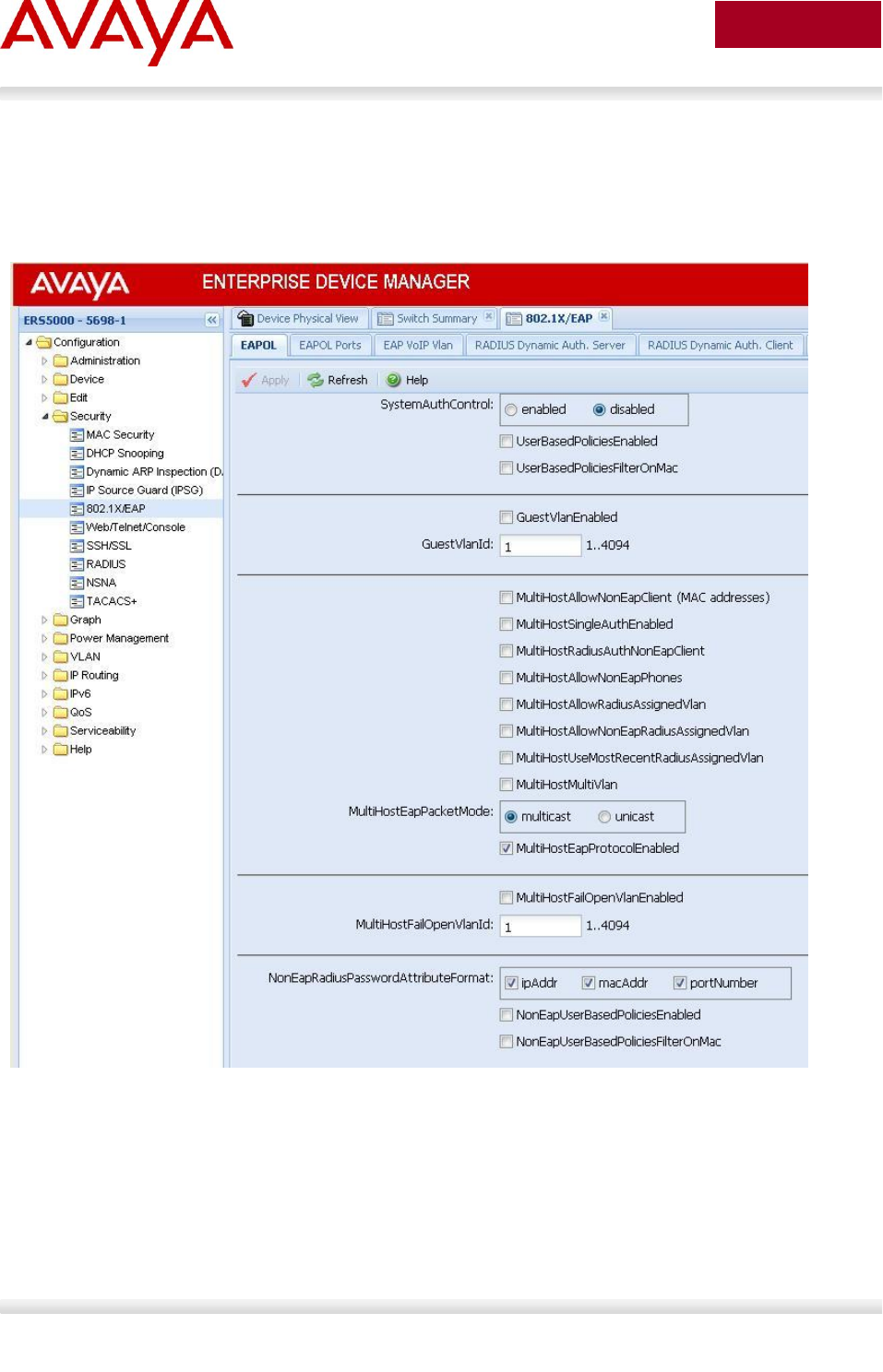
Avaya Inc. – External Distribution
262
avaya.com
Aug 2012
10.6 EAP Configuration using EDM
Global Settings
Go to Configuration -> Security -> 802.1X/EAP
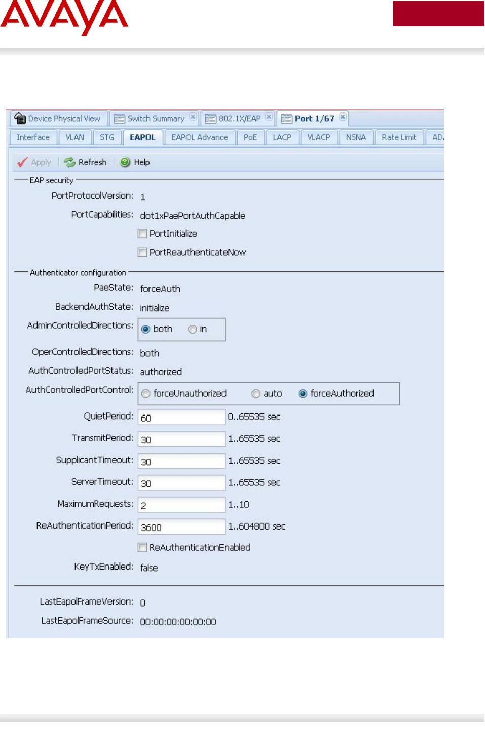
Avaya Inc. – External Distribution
263
avaya.com
Aug 2012
Interface Settings – Base Settings
Go to Device Physical View -> (select port(s), right-click and select Edit -> EAPOL
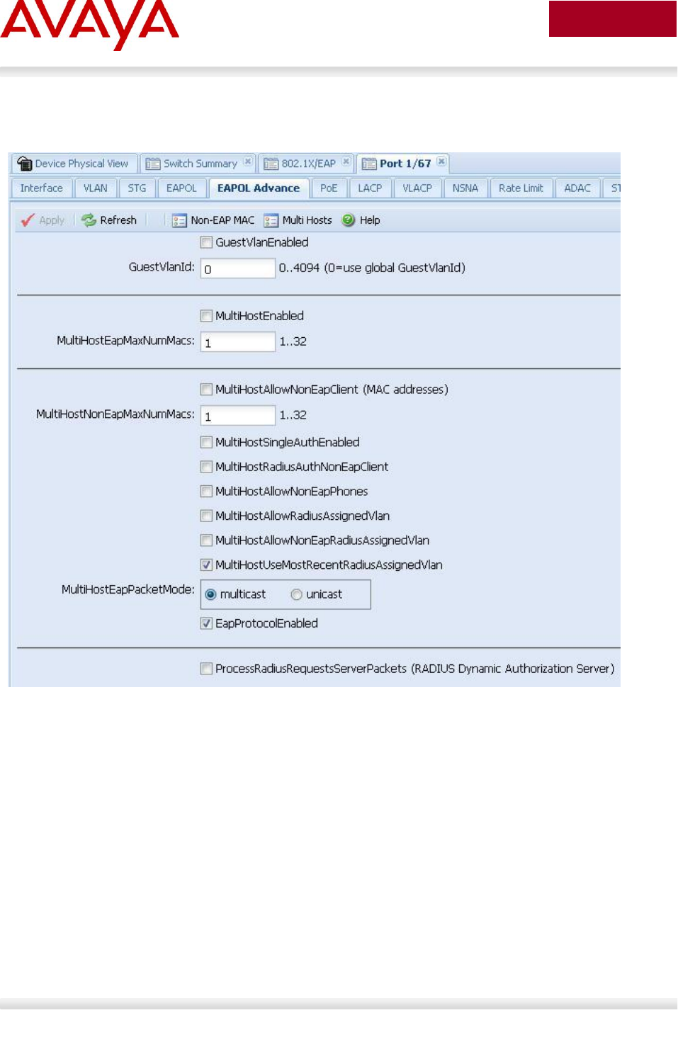
Avaya Inc. – External Distribution
264
avaya.com
Aug 2012
Interface Settings – Advance Settings
Go to Device Physical View -> (select port(s), right-click and select Edit -> EAPOL Advance
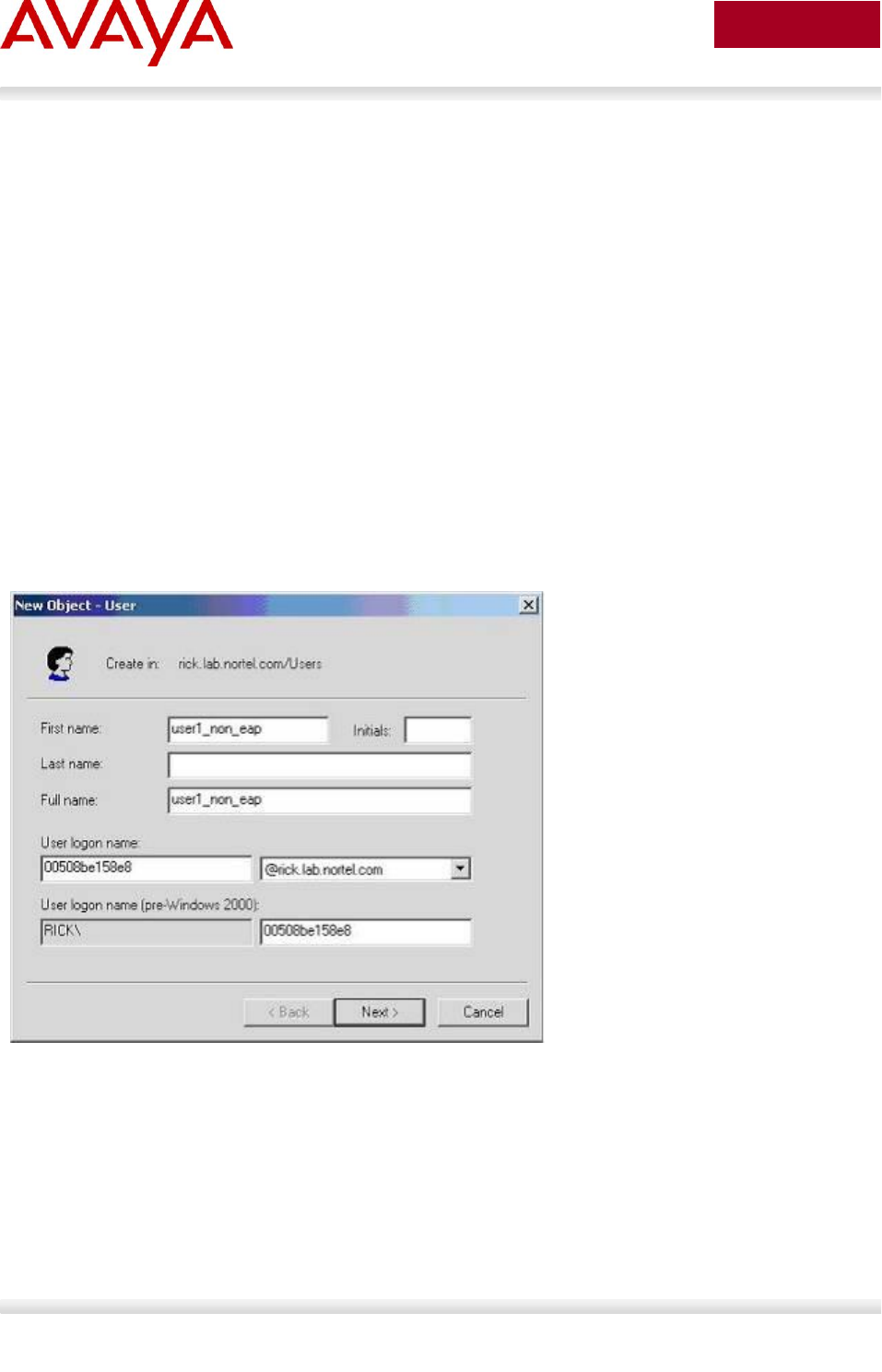
Avaya Inc. – External Distribution
265
avaya.com
Aug 2012
10.7 RADIUS Setup
10.7.1 RADIUS Setup for NEAP
10.7.1.1 Microsoft IAS Server
When setting up the RADIUS server, the user name is the non-eap MAC address. The password is one
of or a combination of the non-eap MAC address, source-IP address and the physical port of the non-eap
MAC as a string separated by dots. For example, assuming the non-eap MAC is 00:50:8b:e1:58:e8, the
non-eap source-IP is 11.1.46.5 and the port number for the client is 1/21, this will result in a user name of
00508be158e8 and password of 011001046005.00508be158e8.0121 assuming use the non-eap
password format of MAC, IP and port number.
For a Microsoft IAS, the non-eap user is entered as follows:
1) Go to Active Directory for Users and Computers, right-click on Users and select New>User
2) Add new user using the MAC address of the PC as the User logon name.
3) Next, enter the Password shown above (011001046005.00508be158e8.0121) and click on Finish
when done.
4) Next, right-click on the user you just created and select Properties
In the Dial-in dialog box, select Allow Access
In the Member Of dialog box, click on Add and add RAS and IAS Servers
Finally, in the Account dialog box, under Account options, click on Store Password using reverse
encryption
5) Enable the IAS Authentication profile for MD5-Challenge with PAP/SPAP selected.

Avaya Inc. – External Distribution
266
avaya.com
Aug 2012
10.7.1.2 Avaya Identity Engines
IDE Step 1 – Go to Site Configuration -> Access Policies -> RADIUS
Right-click RADIUS and select New Access Policy. Enter a policy name, i.e. ERS-
EAP as used in this example and click on OK when done
Click on the policy we just created, i.e. ERS-EAP, and click on Edit via the
Authentication Policy tab. Under Edit Authentication Policy window, select NONE ->
PAP and any additional authentication protocols you may require. Click on OK when
done.
Go to the Identity Routing tab and click on Edit. Check off the Enable Default
Directory Set and click on OK when done.
Go to the Authorization Policy tab and click on Edit.
o Once the Edit Authorization Policy window pops up, click on Add under Rules
and via the name pop-up box, enter a name, i.e. EAP as used in this
example
o Click on the rule named EAP, click on New to add a new constraint. From
Attribute Category, select User and scroll down and select Authentication
Service. Select Equal To with Static Vlaue of Internernal User Store. Click
on OK when done and OK one more time to exit Edit Authentication Policy.
o Clicking on the Access Policy Summary icon should display an Access Policy
similar to that shown below

Avaya Inc. – External Distribution
267
avaya.com
Aug 2012
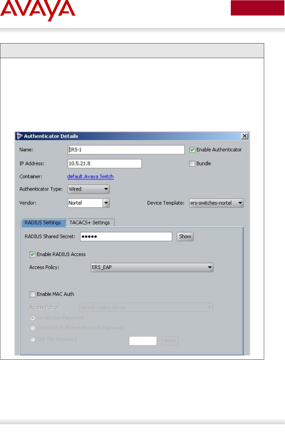
Avaya Inc. – External Distribution
268
avaya.com
Aug 2012
IDE Step 2 – Go to Site Configuration -> Authenticators
For this configuration example, we will create a new container named Avaya Switch
o Under Authenticators, right-click default and add a new container with a
container, add a name of Avaya Switch, and click OK when done
Select Avaya Switch and click on click on New
o Enter the settings as shown below making sure you select the policy we created
above named ERS_EAP via Access Policy. Leave Enable Authenticator and
Enable RADIUS Access checked. Click on OK when done. Please note, the
RADIUS Shared Secret must match the secret entered on the switch

Avaya Inc. – External Distribution
269
avaya.com
Aug 2012
IDE Step 3 – Add Users by going to Site Configuration -> Directories -> Internal Store ->
Internal Users and click on New
Add the NEAP users by going to Directories>Internal Store>Internal Users. Next, enter
the User Name and Password as shown below:
o NEAP user with MAC address of 0050.8be1.58e8 and using a password of MAC
plus IP (11.1.46.5), and port number (1/21)
User Name = 00508be158e8
Password = 011001046005.00508be158e8.0121
DE Step 4 – At the point you are completed. After clicking on the IP address of your IDE
server, go to the Monitor tab and then to Log Viewer -> Access to verify if the non-EAP
client can successfully login.

Avaya Inc. – External Distribution
270
avaya.com
Aug 2012
10.7.1.3 FreeRADIUS Setup
In the radius server’s user configuration file,
1. Add the MAC address of the Non-EAP host as the user name. (ex: “00a0c9a4d0e0”)
2. Set the Auth-Type to ‘local’.
3. Set the User-Password to “Net Mgmt IP of the switch” + ”.” + “Mac address of the Non-EAP host”
+ ”.” + “slot port through which the non-eap client will be connected”. For example, assuming the
management IP address of the switch is 192.168.151.165, the MAC address of the non-EAP host
is 00:a0:c9:a4:d0:e0 and the slot/port is 8/5, enter "192168151165.00a0c9a4d0e0.0805"
4. Set the desired QoS value for the Non-EAP host in the ‘Nortel-Dot1x-Mac-Qos’ attribute. Where,
“Nortel-Dot1x-Mac-Qos” is declared as a vendor-specific-attribute in “dictionary.passport” file as
follows:
ATTRIBUTE Nortel-Dot1x-Mac-Qos 2 integer Nortel
The above declaration describes that “Nortel-Dot1x-Mac-Qos” attribute is a vendor-specific attribute
(Nortel keyword does that). The identifier for this vendor-specific attribute is 2 and the type of the
attribute is integer.
Example:
“192.168.151.165” specifies the net management IP of the switch. User configuration for Non-Eap
host with mac address 00:a0:c9:a4:d0:e0 connected to port 8/5 is given as:
00a0c9a4d0e0 Auth-Type := local, User-Password == "192168151165.00a0c9a4d0e0.0805"
Termination-Action = RADIUS-Request,
Tunnel-Type = VLAN,
Tunnel-Medium-Type = IEEE802,
Tunnel-Private-Group-Id = "0002",
Nortel-Dot1x-Port-Priority = 5,
Nortel-Dot1x-Mac-Qos = 3

Avaya Inc. – External Distribution
271
avaya.com
Aug 2012
10.7.1.4 Steel-Belted Radius Server
To get a non-eap client authenticated using radius server,
1. Ensure that pprt8300 is included in dictiona.dcm file.
2. In the pprt8300 file, add the following return list attribute for returning MAC QoS in the access-accept
packet. The Mac-QoS attribute identifier, i.e. type1 is set to 2 and data is set to integer.
ATTRIBUTE Mac-QoS 26 [vid=1584 type1=2 len1=+2 data=integer]R
VALUE Mac-QoS Level0 0
VALUE Mac-QoS Level1 1
VALUE Mac-QoS Level2 2
VALUE Mac-QoS Level3 3
VALUE Mac-QoS Level4 4
VALUE Mac-QoS Level5 5
VALUE Mac-QoS Level6 6
VALUE Mac-QoS Level7 7
3. In eap.ini file, add the following lines for the Non-EAP client to get authenticated [radiusmac]
EAP-Only = 0
EAP-Type =
First-Handle-Via-Auto-EAP = 0
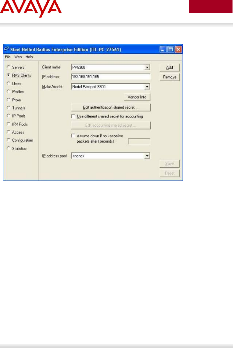
Avaya Inc. – External Distribution
272
avaya.com
Aug 2012
4. Set the RAS-Clients as follows:
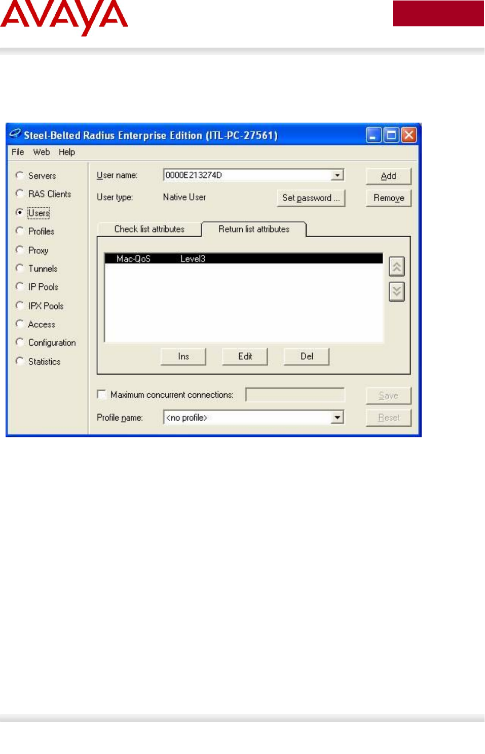
Avaya Inc. – External Distribution
273
avaya.com
Aug 2012
5. Configure the Non-EAP user with user-name, password (as specified in FreeRADIUS section) and
the return list attribute, MAC-QoS.

Avaya Inc. – External Distribution
274
avaya.com
Aug 2012
10.7.2 RADIUS Setup for Dynamic VLAN Assignment
In EAP SHSA or MHMA mode, the RADIUS server can be configured with a Return-Attribute to
dynamically set the VLAN and if required, the port priority.
The following applies to dynamic VLAN assignment:
The dynamic VLAN configuration values assigned by EAPoL are not stored in the switch’s
NVRAM or running configuration file.
You can override the dynamic VLAN configuration values assigned by EAPoL; however, be
aware that the values you configure are not stored in NVRAM.
When EAPoL is enabled on a port, and you configure values other than VLAN configuration
values, those values are applied and stored in NVRAM.
You cannot enable EAPoL on tagged ports or MLT ports.
You cannot change the VLAN/STG membership of EAPoL authorized ports.
To set up the Authentication server, the following RADIUS ‘Return-List’ attributes needs to be set:
VLAN membership attributes:
o Tunnel-Type: value 13, Tunnel-Type-VLAN
o Tunnel-Medium-Type: value 6, Tunnel-Medium-Type-802
o Tunnel-Private-Group-Id: ASCII value 1 to 4094 (this value is used to identify the
specified VLAN) or VLAN name
Port priority (vendor-specific) attributes:
o Vendor Id: value 562, Nortel vendor Id
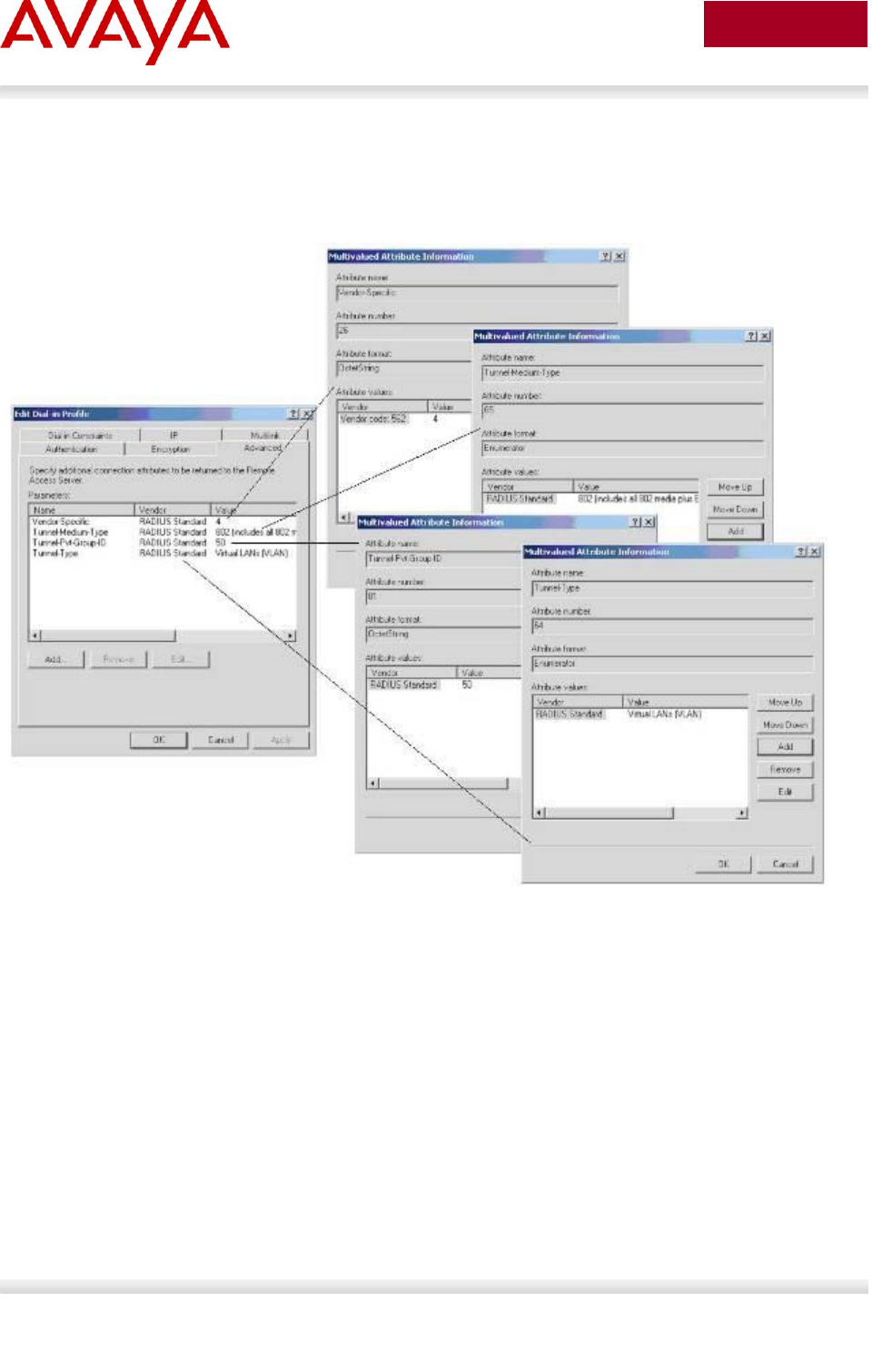
Avaya Inc. – External Distribution
275
avaya.com
Aug 2012
10.7.3 IAS Server
If the Authentication server is a Microsoft IAS server, the configuration would look something like the
following assuming the dynamic VLAN is 50 and the port priority is 4.
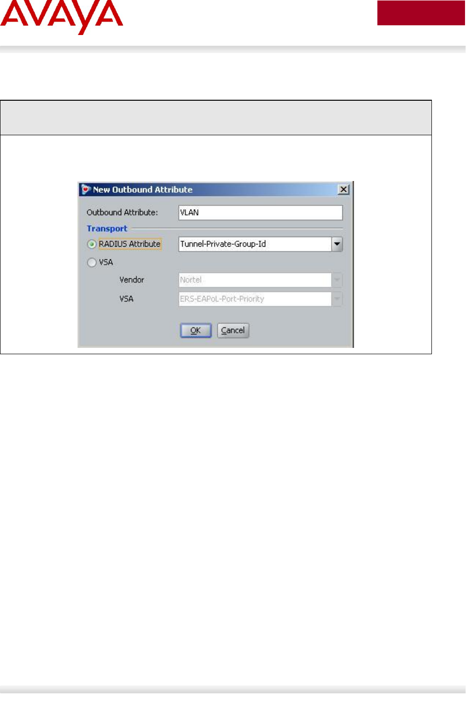
Avaya Inc. – External Distribution
276
avaya.com
Aug 2012
10.7.3.1 Avaya Identity Engines
IDE Step 1 – Configure an Outbound Attribute on Ignition Server for VLAN. Go to Site
Configuration -> Provisioning -> Outbound Attributes -> New
Via the New Outbound Attribute window, enter a name for the attribute (i.e. VLAN as
used in this example), and select Tunnel-Private-Group-Id via the RADIUS Attribute
radio button. Click on OK when done
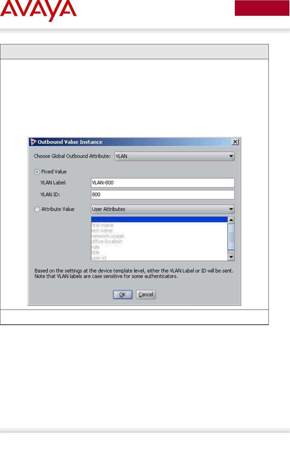
Avaya Inc. – External Distribution
277
avaya.com
Aug 2012
IDE Step 2 – Go to Site Configuration -> Provisioning -> Outbound Values -> New
Using the Outbound Attribute created in Step 1, we will add the VLAN-ID or VLAN-name
value.
o Start by entering a name via the Outbound Value Name: window (i.e. vlan-800
assuming VLAN 800 will be used) and click on New
o Via the Choose Global Outbound Attribute: pull down menu, select the outbound
attribute we created in step 1 (VLAN). Make sure the Fixed Value radio button is
selected. Enter a name (i.e. VLAN-800 as used in this example) in the VLAN
Label: window and enter the correct VLAN number or name (i.e. 800 as used in
this example) in the VLAN ID: window. Click on OK twice when done.
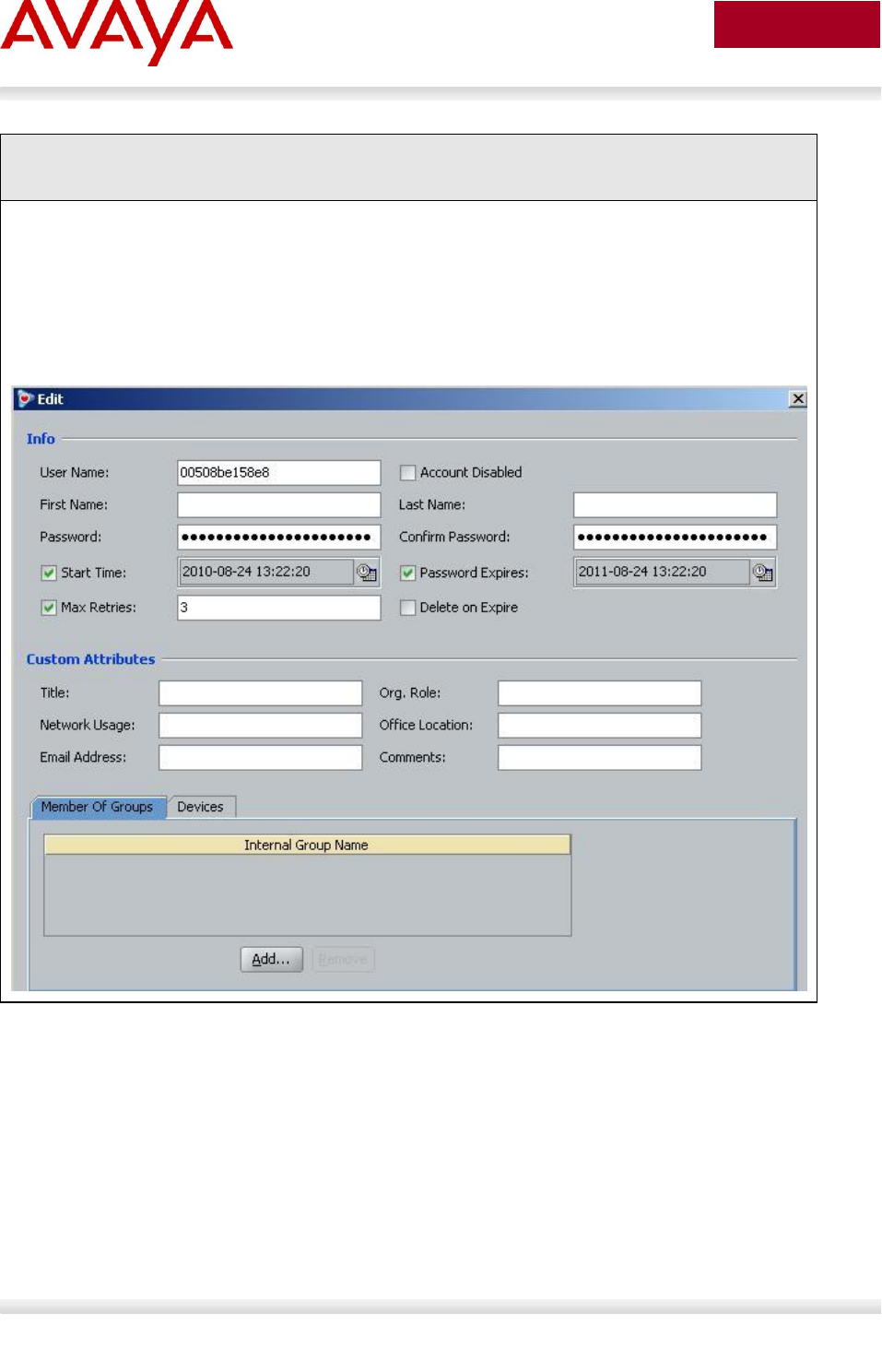
Avaya Inc. – External Distribution
278
avaya.com
Aug 2012
IDE Step 3 – Add Users by going to Site Configuration -> Directories -> Internal Store ->
Internal Users and click on New
Add the NEAP users by going to Directories>Internal Store>Internal Users. Next, enter
the User Name and Password as shown below:
o NEAP user with MAC address of 0050.8be1.58e8 and using a password of MAC
plus IP (11.1.46.5), and port number (1/21)
User Name = 00508be158e8
Password = 011001046005.00508be158e8.0121
Avaya Inc. – External Distribution
279
avaya.com
Aug 2012
11. Appendixes
11.1 Appendix A: IP Deskphone info Block (applies to
the 2001, 2002, 2004, 2007, 1110, 1120E, 1140E,
1150E, 1165E, 1210, 1220, and 1230 IP
Deskphones)
The list of all the parameters that can be provisioned via the Info-Block is provided in the table below. Note that not
all parameters need be specified in the Info-Block. If the option is included, the parameter will be provisioned with
the value specified. If the option is not included, the phone will retain its default value for the particular parameter, or
the phone will retain the value that was previously provisioned for the parameter if the “stickiness” parameter is set.
Info Block Parameters
Parameter
Value
Description
a1
Value from 0 to 255
Primary server action code
a2
Value from 0 to 255
Secondary server action code
ar
‘y’ yes
‘n’ no
Enable Auto-recovery
arl
‘cr’ critical
‘ma’ major
‘mi’ minor
Auto-recovery level
blt
‘0’ 5 seconds
‘1’ 1 minute
‘2’ 5 minutes
‘3’ 10 minutes
‘4’ 15 minutes
‘5’ 30 minutes
‘6’ 1 hour
‘7’ 2 hours
‘8’ always on
Backlight timer
bold
‘y’ yes
‘n’ no
Enable bold on font display
br
Value from 0 to 15
Brightness value

Avaya Inc. – External Distribution
280
avaya.com
Aug 2012
Info Block Parameters
bt
‘y’ yes
‘n’ no
Enable Bluetooth (1140E IP
Deskphone and 1150E only)
ca
Character string up to 80
characters
Certificate Authority (CA) server
cachedip
‘y’ yes
‘n’ no
Enable cached IP
cadomain
Character string up to 50
characters
Certificate Authority (CA) domain name
cahost
Character string up to 32
characters
Certificate Authority (CA) host name
cdiff
Value from 0 to 255
Diffserv code points for control
messages
ct
Value from 0 to 15 for 1100
Series IP Deskphones
Value from 7 to 39 for 2007
IP Deskphone
Contrast value
dcpactive1
‘n’ Inactive
‘y’ Active
Profile is active or not
dcpattrcn1
Character string of 128
characters
If “Auto CN” is disabled, this value is
used instead of combining cadomain
and cahost
dcpattrextkeyusage1
Character string made up of
one of the following
characters
‘a’ anyExtendedKeyUsage
‘c’ clientAuth
‘i’ ipsecIKE (RFC 4945)
‘m’ iKEIntermediate
’ ’ no Extended Key Usage
Define the Extended Key Usage
attributes to be requested for the
device certificate.
The default is clientAuth.
dcpcaname1
Character string of 128
characters
CA name included in the SCEP request
to identify requested CA (note that not
all CA require the CA name)
dcphostnameoverride1
Character string of 128
characters
Override hostname (cahost) for this
DCP only

Avaya Inc. – External Distribution
281
avaya.com
Aug 2012
Info Block Parameters
dcpsource1
‘scep’
‘pkcs12’
Method used to install device
certificates
dhcp
‘y’ yes
‘n’ no
Enable DHCP
dim
‘y’ yes
‘n’ no
As of UNIStim software release 3.4, the
previously supported “dim” parameter
is no longer supported since its
functionality is superseded by the dimt
parameter. The phone will still accept
the dim parameter to prevent errors
when reading existing provisioning files
but the parameter will be ignored in
favor of the new dimt parameter.
dimt
‘0’ Off
‘1’ 5 seconds
‘2’ 1 minute
‘3’ 5 minutes
‘4’ 10 minutes
‘5’ 15 minutes
‘6’ 30 minutes
‘7’ 1 hour
‘8’ 2 hours
Phone inactivity timer to dim the screen
(2007 IP Deskphone only)
dns
Character string up to 50
characters
Primary DNS server URL
dns2
Character string up to 50
characters
Secondary DNS server URL
dp
Value from 0 to 8
802.1Q p bit for data stream.
Provisioning this value to 8 tells the
phone to use the value it receives from
the LLDP Network Policy TLV or from
the call server
dq
‘y’ yes
‘n’ no
Enable 802.1Q for PC port
dscpovr
‘y’ yes
‘n’ no
DSCP Precedence Override

Avaya Inc. – External Distribution
282
avaya.com
Aug 2012
Info Block Parameters
dv
‘y’ yes
‘n’ no
Enable VLAN for data
dvid
Value from 1 to 4094
VLAN ID for data VLAN
eap
‘dis’ disable
‘md5’ EAP-MD5
‘peap’ PEAP/MD5
‘tls’ EAP-TLS
Disable or choose an EAP
authentication method [1] [2]
eapid1
Character string up to 32
characters
802.1x (EAP) device ID1 [1] [2]
eapid2
Character string up to 32
characters
802.1x (EAP) device ID2 [1] [2]
eappwd
Character string up to 32
characters
802.1x (EAP) password [1] [2]
file
Character string up of the
following character
‘z’ read zone file
‘t’ read type file
‘d’ read device file
For system specific provisioning file
specifies what other provisioning files
to read
fs
‘y’ enabled
‘n’ disabled
Font smoothing enabled [3]
hd
Character string up of the
following character
‘w’ wired
‘b’ Bluetooth
‘n’ none
Headset type
igarp
‘y’ yes
‘n’ no
Ignore GARP
ll
‘cr’ critical
‘ma’ major
‘mi’ minor
Log level
lldp
‘y’ yes
‘n’ no
Enable 802.1ab LLDP [1]
Avaya Inc. – External Distribution
283
avaya.com
Aug 2012
Info Block Parameters
mdiff
Value from 0 to 255
Diffserv code points for media
messages
menulock
‘f’ full lock
‘p’ partial lock
‘u’ unlock
Menu lock mode
menupwd
String between and 21
characters containing only
numeric digits, asterisk (*)
and hash (#) – i.e. only the
dialpad symbols
Administrator password [2]
nid
‘a’ auto negotiation
‘f’ full duplex
‘h’ half duplex
Network port duplex [1]
nis
‘a’ auto negotiation
‘10’ 10 Mbps
‘100’ 100 Mbps
Network port speed [1]
ntqos
‘y’ yes
‘n’ no
Enable Avaya Automatic QoS
of
‘y’ enabled
‘n’ disabled
Outlined font enabled [3]
p1
Value from 1 to 65535
Primary server port number
p2
Value from 1 to 65535
Secondary server port number
pc
‘y’ yes
‘n’ no
Enable PC port
pcd
‘a’ auto negotiation
‘f’ full duplex
‘h’ half duplex
PC port duplex
pcs
‘a’ auto negotiation
‘10’ 10 Mbps
‘100’ 100 Mbps
PC port speed
pcuntag
‘y’ yes
‘n’ no
Enable stripping of tags on packets
forwarded to PC port
Avaya Inc. – External Distribution
284
avaya.com
Aug 2012
Info Block Parameters
pk1
Character string of16
character representing 16
hexadecimal digits
S1 PK [2]
pk2
Character string of 16
character representing 16
hexadecimal digits
S2 PK [2]
prov
Character string up to 50
characters
Provisioning server address or URL (if
the string is prefixed with “http://” the
phone will connect to a HTTP server,
otherwise the phone will connect to a
TFTP server)
r1
Value from 0 to 255
Primary server retry count
r2
Value from 0 to 255
Secondary server retry count
s1ip
Value from 0.0.0.0 to
255.255.255.255
Primary server IP address
s2ip
Value from 0.0.0.0 to
255.255.255.255
Secondary server IP address
si
‘y’ enabled
‘n’ disabled
Simple icons enabled [3]
srtp
‘y’ yes
‘n’ no
Enable SRTP-PSK
srtpid
96
115
120
Payload type ID
ssh
‘y’ yes
‘n’ no
Enable SSH
sshid
Character string between 4
and 12 characters
SSH user ID [2]
sshpwd
Character string between 4
and 12 characters
SSH password [2]

Avaya Inc. – External Distribution
285
avaya.com
Aug 2012
Info Block Parameters
sst
‘0’ Off
‘1’ 1 minute
‘2’ 5 minutes
‘3’ 10 minutes
‘4’ 15 minutes
‘5’ 30 minutes
‘6’ 1 hour
‘7’ 2 hours
Phone inactivity timer to initiate the
slide show (2007 IP Deskphone only)
st
‘y’ yes
‘n’ no
Enable stickiness (provisioning is
persistent in the event a new info block
is not received)
th
‘0’ black theme
‘1’ metallic blue them
‘2’ blue theme
‘3’ orange theme
‘4’ green theme
‘5’ red theme
‘6’ purple theme
Theme [3]
unid
Character string up to 32
characters
Unique network identification
usb
‘y’ enabled
‘n’ disabled
UBS port enabled [3]
usbh
‘y’ enabled
‘n’ disabled
UBS headset device enabled [3]
usbk
‘y’ enabled
‘n’ disabled
UBS keyboard device enabled [3]
usbm
‘y’ enabled
‘n’ disabled
UBS mouse device enabled [3]
usbms
‘y’ enabled
‘n’ disabled
UBS memory stick (flash drive) device
enabled [3]

Avaya Inc. – External Distribution
286
avaya.com
Aug 2012
Info Block Parameters
utb
‘y’ use the selected theme
background
‘n’ use the user selected
image – if present
Use a user selected background
picture [3]
vcp
Value from 0 to 8
802.1Q control p bit for voice stream.
Provisioning this value to 8 tells the
phone to use the value it receives from
the LLDP Network Policy TLV or from
the call server
vlanf
‘y’ yes
‘n’ no
Enable VLAN filter on voice stream
vmp
Value from 0 to 8
802.1Q media p bit for voice stream.
Provisioning this value to 8 tells the
phone to use the value it receives from
the LLDP Network Policy TLV or from
the call server
vpn
‘y’ enable
‘n’ disable
Enable the UNIStim VPN Client (UVC)
within the phone
vpnauth
‘psk’ preshared key
‘certificate’ X.509 certificate
Authentication credential2
vpndiff
0-255
If vpndiffcpy=n, then this value is used
for the DSCP value for the tunnel traffic
vpndiffcpy
‘y’ copy DSCP from inner
packet
‘n’ use vpndiff value
Source of DSCP value for the tunnel
traffic. Determines if DSCP value is
copied from inner packet to outer
packet or if vpndiff is used.
vpnmode
‘aggressive’
‘main’
Authentication mode
vpnmotd
0-999
Message of the Day (MOTD) timer
vpnpskpwd
Character string up to 64
characters
PreShared Key (PSK) password
vpnpskuser
Character string up to 64
characters
PreShared Key (PSK) User ID
2
When ‘certificate’ is provisioned, both a CA root certificate and a device certificates must be installed in the phone. Please refer to
Appendix A: Certificate Installation for details on installing a CA root certificate and a device certificate into the phone.
Avaya Inc. – External Distribution
287
avaya.com
Aug 2012
Info Block Parameters
vpns1
Character string up to 64
characters
IP address or FQDN3 of the primary
VPN server
vpns2
Character string up to 64
characters
IP address or FQDN of the secondary
VPN server
vpntype
‘1’ Avaya VPN
Only Avaya (heritage Nortel) VPN
devices are supported at this time
vpnxauth
‘0’ none
‘1’ password
X Authentication type
vpnxauthpwd
Character string up to 64
characters
X Authentication password
vpnxauthuser
Character string up to 64
characters
X Authentication User ID
vq
‘y’ yes
‘n’ no
Enable 802.1Q for voice [1]
vvsource
‘n’ no VLAN
‘a’ auto VLAN via DHCP
‘lv’ auto VLAN via VLAN
Name TLV
‘lm’ auto VLAN via Network
Policy TLV
Source of VLAN information
3
If a FQDN is entered, the remote user’s local network must have access to DNS to resolve the entered name. Typically in a home
environment, this would be the service provider’s DNS.

Avaya Inc. – External Distribution
288
avaya.com
Aug 2012
Info Block Parameters
xa
Character string made up of
the following character
‘g’ graphical XAS mode
‘f’ full screen XAS mode
‘s’ secure XAS mode
‘h’ hidden Phone mode
‘r’ reduced Phone mode
XAS server action code (XAS Mode
and Phone Mode)
Note that there is no explicit character
to select text-mode. Instead, the lack of
specifying graphical ‘g’ implies the XAS
mode is text.
Also note that there is no explicit
character to select Full phone mode.
Instead, the lack of specifying either
hidden ‘h’ or reduced ‘r” implies the
phone is to be provisioned for Full
phone mode. Please be careful not to
confuse Full Screen XAS mode ‘f’ with
Full phone mode.
Note that hidden Phone mode and
reduced Phone mode are supported on
the 2007 IP Deskphone only.
xatv
‘0’ no tone
‘1’ -36dB
‘2’ -26dB
‘3’ -20dB
‘4’ -16dB
‘5’ -13dB
‘6’ -9dB
‘7’ -6dB
‘8’ 0dB
Alternate tone volume
xip
Value from 0.0.0.0 to
255.255.255.255
XAS server IP address
xp
Value from 0 to 65535
XAS server port number
zone
Character string up to 8
characters
Zone ID
[1]: Warning - changing this parameter could impact the network connectivity and may require manual correction
[2]: Warning – provisioning this parameter via TFTP, HTTP, or DHCP means that secure information is transferred in
clear text
[3]: Applies to the 1165E IP Deskphone only

Avaya Inc. – External Distribution
289
avaya.com
Aug 2012
11.2 Appendix B: DHCP Configurable Parameters –
Avaya 9600 Series H323 IP Phones
Parameter
Description
DOT1X
Controls the operational mode for 802.1X. The default is 0 (pass-through of
multicast EAPOL messages to an attached PC, and enable Supplicant
operation for unicast EAPOL messages).
DOT1XSTAT
Controls 802.1X Supplicant operation.
HTTPDIR
Specifies the path name to prepend to all file names used in HTTP and
HTTPS GET operations during startup. (0 to 127 ASCII characters, no
spaces.) The command is “SET HTTPDIR myhttpdir”. The path (relative to
the root of the TLS or HTTP file server) where 96xx telephone files are stored.
If an Avaya file server is used to download configuration files over TLS, but a
different server is used to download software files via HTTP, set the path of
the Avaya server in the DHCP site-specific option, and set HTTPDIR again in
the 46xxsettings.txt file with the appropriate path for the second server.
HTTPDIR is the path for all HTTP operations except for BRURI.
HTTPPORT
Specifies the TCP port number to be used for HTTP file downloading.
HTTPSRVR
IP Address(es) or DNS name(s) of HTTP file server(s) used for file download
(settings file, language files, code) during startup. The files are digitally
signed, so TLS is not required for security.
ICMPDU
Controls the extent to which ICMP Destination Unreachable messages are
sent in response to messages sent to closed ports so as not to reveal
information to potential hackers. The default is 1 (sends Destination
Unreachable messages for closed ports used by traceroute).
ICMPRED
Controls whether ICMP Redirect messages are processed. The default is 0
(redirect messages are not processed).
L2Q
802.1Q tagging mode. The default is 0 (automatic).
L2QVLAN
VLAN ID of the voice VLAN. The default is 0.
LOGLOCAL
Controls the severity level of events logged in the SNMP MIB. The default is
7.
MCIPADD
CM server(s) IP Address(es) or DNS name(s). If there are too many
addresses or names to include all of them in the DHCP site-specific option,
include at least one from each major system. Then set MCIPADD again in the
46xxsettings.txt file with the complete list of addresses. Providing a subset of
the addresses via DHCP improves reliability if the file server is not available
due to server or network problems.
PHY1STAT
Controls the Ethernet line interface speed. The default is 1 (auto-negotiate).

Avaya Inc. – External Distribution
290
avaya.com
Aug 2012
Parameter
Description
PHY2STAT
Controls the secondary Ethernet interface speed. The default is 1 (auto-
negotiate).
PROCPSWD
Security string used to access local procedures. The default is 27238.
PROCSTAT
Controls whether local procedures are enabled. The default is 0 (enabled).
SNMPADD
Allowable source IP Address(es) for SNMP queries. The default is " " (Null).
SNMPSTRING
SNMP community name string. The default is " " (Null).
STATIC
Controls whether to use a manually-programmed file server or CM IP Address
instead of those received via DHCP or a settings file. If a manually-
programmed file server IP Address is to be used, STATIC must be set via
DHCP.
TLSDIR
Specifies the path name prepended to all file names used in HTTPS GET
operations during startup.
TLSPORT
Specifies the TCP port number used for HTTPS file downloading.
TLSSRVR
IP Address(es) or DNS name(s) of Avaya file server(s) used to download
configuration files.
Note: Transport Layer Security is used to authenticate the server.
VLANTEST
Controls the length of time the telephone tries DHCP with a non-zero VLAN
ID. When the interval is exceeded, the telephone records the VLAN ID so that
it is not used again, and DHCP continues on the default VLAN. The default is
60 seconds.

Avaya Inc. – External Distribution
291
avaya.com
Aug 2012
11.3 Appendix C: DHCP Configurable Parameters –
Avaya 9600 Series SIP IP Phones
Parameter
Description
HTTPDIR
Specifies the path to prepend to all configurations and data files
the phone might request when starting up, i.e., the path, relative to
the root of the HTTP file server, to the directory in which the
telephone configuration and date files are stored. The path may
contain no more than 127 characters and may contain no spaces.
If an Avaya file server is used to download configuration files over
HTTPS, but a different server is used to download software files
via HTTP, set the path of the Avaya server in the DHCP site-
specific option, and set HTTPDIR again in the 46xxsettings.txt file
with the appropriate path for the second server. HTTPDIR is the
path for all HTTP operations. The command is "SET
HTTPDIR=<path>". In configurations where the
upgrade(96xxupgrade.txt) and binary files are in the default
directory on the HTTP server, do not use the HTTPDIR=<path>.
HTTPPORT
Destination port for HTTP requests (default is 80).
HTTPSRVR
IP Address(es) or DNS name(s) of HTTP file server(s) used for file
download (settings file, language files, code) during startup. The
files are digitally signed, so TLS is not required for security.
ICMPDU
Controls the extent to which ICMP Destination Unreachable
messages are sent in response to messages sent to closed ports
so as not to reveal information to potential hackers. The default is
1 (sends Destination Unreachable messages for closed ports used
by traceroute).
ICMPRED
Controls whether ICMP Redirect messages are processed. The
default is 0 (redirect messages are not processed).
L2Q
802.1Q tagging mode. The default is 0 (automatic).
L2QVLAN
VLAN ID of the voice VLAN. The default is 0.
LOGSRVR
Syslog server IP or DNS address.
MTU_SIZE
Maximum transmission unit size. Used to accommodate older
Ethernet switches that cannot support the longer maximum frame
length of tagged frames (since 802.1Q adds 4 octets to the frame).
PHY1STAT
Controls the Ethernet line interface speed. The default is 1 (auto-
negotiate).
PHY2STAT
Controls the secondary Ethernet interface speed. The default is 1
(auto-negotiate).

Avaya Inc. – External Distribution
292
avaya.com
Aug 2012
Parameter
Description
PROCPSWD
Security string used to access local procedures. The default is
27238.
PROCSTAT
Controls whether local procedures are enabled. The default is 0
(enabled).
SIP_CONTROLLER_LIST
SIP proxy/registrar server IP or DNS address(es). (0 to 255
characters; zero or one IP Address in dotted decimal or DNS
name format, separated by commas without any intervening
spaces.) The default is null.
SNTPSRVR
List of SNTP server IP or DNS address(es) used to retrieve date
and time via SNTP
TLSDIR
Used as path name that is prepended to all file names used in
HTTPS
TLSPORT
Destination TCP port used for requests to https server (0-65535).
Thedefault is 443.
TLSSRVR
IP Address(es) or DNS name(s) of Avaya file server(s) used
todownload configuration files.
Note: Transport Layer Security is used to authenticate the server.
VLANTEST
Number of seconds to wait for a DHCPOFFER on a non-zero
VLAN.
The default is 60 seconds.

Avaya Inc. – External Distribution
293
avaya.com
Aug 2012
11.4 Appendix D: DHCP Configurable Parameters –
Avaya 1600 Series H.323 IP Deskphones
Parameter
Description
AGCHAND
Automatic Gain Control status for handset
AGCHEAD
Automatic Gain Control status for headset
AGCSPKR
Automatic Gain Control status for speaker
APPNAME
Primary application image file name
APPSTAT
Controls whether specific applications are enabled, restricted, or disabled.
AUTH
Script file authentication value (0=HTTP is accepted, 1=HTTPS is accepted)
BAKLIGHTOFF
Number of minutes without display activity to wait before turning off the
backlight.
BRURI
URL used for backup and retrieval of user data.
DHCPSTD
DHCP Standard leave violation flag.
DNSSRVR
Text string containing the IP address of zero or more DNS servers.
DOMAIN
Text string containing the domain name to be used when DNS names in
system values are resolved into IP addresses.
DOT1X
Controls the operational mode for 802.1X. The default is 0 (pass-through of
multicast EAPOL messages to an attached PC, and enable Supplicant
operation for unicast EAPOL messages).
DOT1XSTAT
Controls 802.1X Supplicant operation.
ENHDIALSTAT
Enhanced Dialing Status.
FONTFILE
Name of the font file for a language for a 1600 Series International
Deskphone
HTTPDIR
Specifies the path name to prepend to all file names used in HTTP and
HTTPS GET operations during startup. (0 to 127 ASCII characters, no
spaces.) The command is “SET HTTPDIR myhttpdir”. The path (relative to
the root of the TLS or HTTP file server) where 96xx telephone files are stored.
If an Avaya file server is used to download configuration files over TLS, but a
different server is used to download software files via HTTP, set the path of
the Avaya server in the DHCP site-specific option, and set HTTPDIR again in
the 46xxsettings.txt file with the appropriate path for the second server.
HTTPDIR is the path for all HTTP operations except for BRURI.

Avaya Inc. – External Distribution
294
avaya.com
Aug 2012
Parameter
Description
HTTPSRVR
IP Address(es) or DNS name(s) of HTTP file server(s) used for file download
(settings file, language files, code) during startup. The files are digitally
signed, so TLS is not required for security.
ICMPDU
Controls the extent to which ICMP Destination Unreachable messages are
sent in response to messages sent to closed ports so as not to reveal
information to potential hackers. The default is 1 (sends Destination
Unreachable messages for closed ports used by traceroute).
ICMPRED
Controls whether ICMP Redirect messages are processed. The default is 0
(redirect messages are not processed).
L2Q
802.1Q tagging mode. The default is 0 (automatic).
L2QVLAN
VLAN ID of the voice VLAN. The default is 0.
LANG0STAT
Controls whether the built-in English language text strings can be selected by
the user.
LANGxFILE
Name of the language file in use.
LANGSYS
The file name of the system default language file, if any.
LOGLOCAL
Controls the severity level of events logged in the SNMP MIB.
LOGSRVR
Voice Monitoring Manager (VMM) Server Address
MCIPADD
CM server(s) IP Address(es) or DNS name(s). If there are too many
addresses or names to include all of them in the DHCP site-specific option,
include at least one from each major system. Then set MCIPADD again in the
46xxsettings.txt file with the complete list of addresses. Providing a subset of
the addresses via DHCP improves reliability if the file server is not available
due to server or network problems.
MSGNUM
Voice Mail telephone number.
OPSTAT
Options status flag(s) indicate which options are user-selectable.
PHNCC
Telephone country code.
PHNDPLENGTH
Internal extension telephone number length.
PHNIC
Telephone international access code
PHNLD
Telephone long distance access code
PHNLDLENTGH
Length of national telephone number.
PHNOL
Outside line access code.

Avaya Inc. – External Distribution
295
avaya.com
Aug 2012
Parameter
Description
PHY1STAT
Controls the Ethernet line interface speed. The default is 1 (auto-negotiate).
PHY2PRIO
Layer 2 priority value for frames received on or forwarded to the secondary
Ethernet interface. Set this parameter only when VLAN separation is “1”
(enabled).
PHY2STAT
Controls the secondary Ethernet interface speed. The default is 1 (auto-
negotiate).
PHY2VLAN
VLAN identifier used by frames received on or forwarded to the secondary
Ethernet interface. Set this parameter only when VLAN separation is “1”
(enabled). If this value is set by LLDP using the Port VLAN ID TLV value, it
will not change regardless of the settings from other sources.
PROCPSWD
Security string used to access local procedures. The default is 27238.
PROCSTAT
Controls whether local procedures are enabled. The default is 0 (enabled).
REREGISTER
Registration time in minutes.
RTCPMON
Text string containing the 4-octet IP address of the RTCP monitor currently in
use.
SNMPADD
Allowable source IP Address(es) for SNMP queries. The default is " " (Null).
SNMPSTRING
SNMP community name string. The default is " " (Null).
STATIC
Controls whether to use a manually-programmed file server or CM IP Address
instead of those received via DHCP or a settings file. If a manually-
programmed file server IP Address is to be used, STATIC must be set via
DHCP.
SUBSCRIBELIST
One or more Push application server subscription URLs.
TPSLIST
One or more trusted domain/path strings.
UNNAMEDSTAT
Unnamed Registration Status
VLANSEP
VLAN Separation. Controls whether frames to/from the secondary Ethernet
interface receive IEEE 802.1Q tagging treatment. This parameter is used with
several related paramaters.
VLANTEST
Controls the length of time the telephone tries DHCP with a non-zero VLAN
ID. When the interval is exceeded, the telephone records the VLAN ID so that
it is not used again, and DHCP continues on the default VLAN. The default is
60 seconds.

Avaya Inc. – External Distribution
296
avaya.com
Aug 2012
11.5 Appendix E: DHCP Configurable Parameters –
Avaya 1600 Series SIP IP Deskphones
Parameter
Description
HTTPDIR
Specifies the path name to prepend to all file names used in HTTP and
HTTPS GET operations during startup. (0 to 127 ASCII characters, no
spaces.) The command is “SET HTTPDIR myhttpdir”. The path (relative to
the root of the TLS or HTTP file server) where 96xx telephone files are stored.
If an Avaya file server is used to download configuration files over TLS, but a
different server is used to download software files via HTTP, set the path of
the Avaya server in the DHCP site-specific option, and set HTTPDIR again in
the 46xxsettings.txt file with the appropriate path for the second server.
HTTPDIR is the path for all HTTP operations except for BRURI.
HTTPPORT
Destination port for HTTP requests.
HTTPSRVR
IP Address(es) or DNS name(s) of HTTP file server(s) used for file download
(settings file, language files, code) during startup. The files are digitally
signed, so TLS is not required for security.
ICMPDU
Controls the extent to which ICMP Destination Unreachable messages are
sent in response to messages sent to closed ports so as not to reveal
information to potential hackers. The default is 1 (sends Destination
Unreachable messages for closed ports used by traceroute).
ICMPRED
Controls whether ICMP Redirect messages are processed. The default is 0
(redirect messages are not processed).
L2Q
802.1Q tagging mode. The default is 0 (automatic).
L2QVLAN
VLAN ID of the voice VLAN. The default is 0.
LOGSRVR
Voice Monitoring Manager (VMM) Server Address
MTU_SIZE
Maximum transmission unit size.
PHY1STAT
Controls the Ethernet line interface speed. The default is 1 (auto-negotiate).
PHY2STAT
Controls the secondary Ethernet interface speed. The default is 1 (auto-
negotiate).
PROCPSWD
Security string used to access local procedures. The default is 27238.
PROCSTAT
Controls whether local procedures are enabled. The default is 0 (enabled).
REREGISTER
Registration time in minutes.
SIP_CONTROLLE
SIP proxy/registrar server IP or DNS address(es).

Avaya Inc. – External Distribution
297
avaya.com
Aug 2012
Parameter
Description
R_LIST
TLSDIR
Used as path name that is prepended to all fine names used in HTTPS GET
operations during initialization.
TLSSRVR
IP Address(es) or DNS name(s) of Avaya file server(s) used to download
configuration files.
VLANTEST
Controls the length of time the telephone tries DHCP with a non-zero VLAN
ID. When the interval is exceeded, the telephone records the VLAN ID so that
it is not used again, and DHCP continues on the default VLAN. The default is
60 seconds.

Avaya Inc. – External Distribution
298
avaya.com
Aug 2012
11.6 Appendix F: 46xxsettings.txt Configuration File
############################################################
## ##
## AVAYA IP TELEPHONE CONFIGURATION FILE TEMPLATE ##
## *** Aug 31, 2010 *** ##
## ##
## ##
## This file is to be used as a template for configuring ##
## Avaya IP telephones. This file lists parameters ##
## supported through the following software releases: ##
## ##
## 16xx telephone H.323 software release 1.3 ##
## 1603 telephone SIP software release 1.0 ##
## 96xx telephone SIP software release 2.6 ##
## 96xx telephone SIP software release 2.5 ##
## 96xx telephone SIP software release 2.4.2 ##
## 96xx telephone SIP software release 2.4.1 ##
## 96xx telephone SIP software release 2.2 ##
## 96x1 telephone SIP software release 6.0 ##
## 96x1 telephone H.323 software release 6.0 ##
## 96xx telephone H.323 software release 3.1 ##
## 9670 telephone H.323 software release 2.0 ##
## 96xx telephone H.323 software release 2.0 SP1 ##
## 96xx telephone H.323 software release 1.5 ##
## 46xx telephone H.323 software release 2.9 ##
## 3631 telephone H.323 software release 1.3.0 ##
## 16cc telephone SIP software release 1.0 ##
## 1692 telephone H.323 software release R1.00 ##
## 96xx telephone SIP software release 2.0 ##
## 46xx telephone SIP software release 2.2.2 ##
## SIP Softphone release 2.1 ##
## ##
## Not all parameters are supported on all telephones or ##
## on all software releases. See the appropriate issue ##
## of your telephone's Administrators Guide for more ##
## details. The guides are available on support.avaya.com ##
## ##
############################################################
##
## Use "## " without quotes to comment out a line.
## To activate a setting, set the parameter to the
## appropriate value for your environment and remove the
## "## " from the beginning of the line.
##
## To include white spaces in a value, the entire value
## must be enclosed in double quotes.
## example:
## SET PARAM "value1 value2"
##
## To set different set types to different values, use
## the "IF" keyword statement.
## See the LAN Administrators Guide for more details.
##
## Some of the parameters listed below have default settings
## which are used by the IP Telephones even if they are
## commented out in this file. For a list of those
## settings and their default values, see the LAN
## Administrators Guide.
##

Avaya Inc. – External Distribution
299
avaya.com
Aug 2012
############################################################
############################################################
## ##
## COMMON SETTINGS ##
## Applies to all telephones ##
## ##
############################################################
##
################## HTTP SERVER SETTINGS ##################
##
## HTTP Server Addresses
## [If you set your HTTP Server Addresses via DHCP, do not
## set them here as they will override your DHCP settings.
## Also, use TLSSRVR instead if you require an
## authenticated server]
## Server used to download configuration script files.
## Zero or more HTTP server IP addresses in dotted-decimal, colon-hex (H.323 R6.0
onwards),
## or DNS name format, separated by commas without any
## intervening spaces. (0 to 255 ASCII characters,
## including commas).
## This parameter may also be changed via LLDP.
## SET HTTPSRVR 192.168.0.5
##
## HTTP Server Directory Path
## Specifies the path name to prepend to all file names
## used in HTTP and HTTPS GET operations during startup.
## (0 to 127 ASCII characters, no spaces.)
## SET HTTPDIR myhttpdir
##
## HTTP port
## Sets the TCP port used for HTTP file downloads from
## non-Avaya servers. (0-65535) The default is 80.
## Applies only to 46xx H.323 phones, 96xx phones and 96x1 phones.
## SET HTTPPORT 80
##
## Server Authentication
## Sets whether script files are downloaded from an
## authenticated server over an HTTPS link.
## 0 for optional, 1 for mandatory
## SET AUTH 0
##
################ DOMAIN NAME SYSTEM (DNS) ################
##
## If you set your DNS parameters via DHCP, do not set them
## here as they will over ride your DHCP settings.
##
## Your Domain Name Server
## SET DNSSRVR 198.152.15.15
##
## Your DNS domain
## SET DOMAIN mycompany.com
##
##
############# CALL SERVER ADDRESS OVERRIDE ###############
##
##
## STATIC parameter is not supported by SIP phones.
##
## STATIC specifies whether a call server IP address that

Avaya Inc. – External Distribution
300
avaya.com
Aug 2012
## has been manually programmed into the phone may override
## any value received via DHCP or this settings file.
## 0 for disabled. File server and call server IP addresses received via DHCP or
## via a configuration file are used instead of manually programmed values
## 1 for allowing manually programmed file server IP address.
## 2 for allowing manually programmed call server IP address.
## 3 for allowing manually programmed file server and call server IP addresses.
##
## SET STATIC 0
##
################# DHCP ADDRESS SETTINGS ##################
##
## DHCPSTD controls whether the phone continues to use an
## expired IP address if the phone received no response to
## its address renewal request. 0 for yes, 1 for no.
##
## SET DHCPSTD 0
##
## VLANTEST specifies the number of seconds to wait for a
## DHCPOFFER when the phone is using a non-zero VLAN ID.
## (0-999)
##
## SET VLANTEST 60
##
###################### LOGIN SETTINGS ######################
##
## QKLOGINSTAT specifies whether a password must always be
## entered manually at the login screen.For 96XX SIP Phones ,
## default value is 0 and 'Press Continue softkey to accept
## the current password'
##
## 0 : makes manual password entry mandatory.
## 1 : enables a "quick login' by pressing the
## # key to accept the current password value.
##
## SET QKLOGINSTAT 0
##
###################### SIG SETTINGS ######################
## Variable Name : SIG
## Valid Values
## 0 Default
## 1 H.323
## 2 SIP
##
## Description
## Signaling protocol download flag
##
## SET SIG 1
## Note: This setting is applicable for 96x1 phone models
##
############# ENHANCED LOCAL DIALING RULES ###############
##
## These settings affect certain dialing behaviors, such as
## dialing numbers from the incoming Call Log or from web
## pages
##
## Dialing Algorithm Status
## Controls whether algorithm defined by parameters in
## this section is used during certain dialing behaviors.
## 0 disables algorithm.
## 1 enables algorithm, but not for Contacts

Avaya Inc. – External Distribution
301
avaya.com
Aug 2012
## 2 enables algorithm, including Contacts (96xx SIP only)
## SET ENHDIALSTAT 1
##
## Country Code
## For United States the value is '1'
## SET PHNCC 1
##
## Internal extension number length
## If your extension is 12345, your dial plan length is 5.
## On 46xx phones, the maximum extension length is 10.
## On 96xx phones, the maximum extension length is 13.
## This value must match the extension length set on your
## call server.
## SET PHNDPLENGTH 5
##
## International access code
## For the United States, the value is 011.
## SET PHNIC 011
##
## Long distance access code
## SET PHNLD 1
##
## National telephone number Length
## For example, 800-555-1111 has a length of 10.
## SET PHNLDLENGTH 10
##
## Outside line access code
## The number you press to make an outside call.
## SET PHNOL 9
##
##
############### Emergency Contact Number ##############
##
## If set, this number will be the top-leftmost speed dial
## button in Group 1 of the 46xx speed dial screen and
## labeled "EMERGENCY". The default is null ("") but any
## valid phone number is acceptable.
## If set in the case of 96xx phones, this is the number
## dialed when the softkey labeled "Emerg." is pressed.
## The default is null ("") but any valid phone number is acceptable.
##
## Note 1: This parameter is not supported on phone model 3631.
## Note 2: This setting is applicable for 1603 phone models also.
## SET PHNEMERGNUM 911
##
############## APPLICATION ACCESS SETTINGS ###############
##
## These settings restrict access to certain applications.
## APPSTAT is not supported on 96xx or 16cc SIP phones.
##
## When APPSTAT is set to 0, Call Log and Redial are
## suppressed and changes to Speed Dial/Contacts are not allowed.
##
## When APPSTAT is set to 1, Call Log, Redial and,
## Speed Dial/Contacts work without restrictions.
##
## When APPSTAT is set to 2, Call Log is suppressed.
## For Redial the Last-6-numbers option is suppressed
## and changes to Speed Dial/Contacts are not allowed.
##
## When APPSTAT is set to 3, changes to Speed Dial/Contacts

Avaya Inc. – External Distribution
302
avaya.com
Aug 2012
## are not allowed.
##
## SET APPSTAT 1
##
##
################# OPTION ACCESS SETTINGS #################
##
## This setting restricts access to certain user options.
## OPSTAT is not supported on 96xx or 16cc SIP phones.
##
## When OPSTAT is set to 000, the user options
## are not accessible.
##
## When OPSTAT is set to 001, the user can only access
## the Log-Off Option.
##
## When OPSTAT is set to 010, the user can only access
## view-only options. The user cannot change any setting.
##
## When OPSTAT is set to 011, the user can only access
## view-only options and the Log-Off Option.
##
## When OPSTAT is set to 100, the user can access
## all options except the view-only options and
## the Log-Off option.
##
## When OPSTAT is set to 101, the user can access
## all options except the view-only options.
##
## When OPSTAT is set to 110, the user can access
## all the options except the Log-Off option.
##
## When OPSTAT is set to 111, the user can invoke
## any or all of the user options.
## Note : This setting is applicable for 1603 SIP phones also.
## SET OPSTAT 111
##
##
############# LOCAL PROCEDURE ACCESS SETTINGS ############
##
## Restrict Local Procedure Access
## Controls whether local (dial pad) procedures can be
## used to administer the telephone.
## 0 means local procedures can be accessed from the
## telephone.
## 1 means local procedures can not be accessed from the
## telephone.
## CAUTION:Be absolutely sure before setting PROCSTAT to 1
## Note : This setting is applicable for 1603 SIP phones also.
## SET PROCSTAT 0
##
## Local Procedure Password
## Sets password for local (dial pad) procedure access.
## (0 to 7 ASCII numeric digits). See your telephone's
## Administrator's guide for the default password
## supported by your release.
## Note : This setting is applicable for 1603 SIP phones also.
## SET PROCPSWD 27238
##
#################### AUDIO SETTINGS ######################
##

Avaya Inc. – External Distribution
303
avaya.com
Aug 2012
## Automatic Gain Control (AGC).
## These settings enable or disable AGC.
##
## A value of 1 (default) enables AGC. A value of 0 disables AGC.
## AGCHAND controls handset AGC. Not supported on 16cc phones.
## AGCHEAD controls headset AGC
## AGCSPKR controls speaker AGC. Not supported on 16cc phones.
## Note: AGCHAND and AGCSPKR are applicable for 1603 SIP phone.
## SET AGCHAND 0
## SET AGCHEAD 0
## SET AGCSPKR 0
##
## Headset Operational Mode
## Controls whether the headset ignores a disconnect
## message.
##
## A value of 0 or 2 makes the headset go on-hook when it
## receives a disconnect message.
## A value of 1 or 3 makes the headset ignore a disconnect
## message.
##
## SET HEADSYS 1
##
## Audio Environment Index
## Enables you to customize the telephone's audio
## performance. (0-299) This parameter affects settings
## for AGC dynamic range, handset and headset noise
## reduction thresholds, and headset transmit gain. It is
## highly recommended you consult Avaya before changing
## this parameter.
##
## SET AUDIOENV 0
##
################# WML BROWSER SETTINGS ###################
##
## This section contains the common settings used to
## enable and administer the 'Web' application. These
## parameters are not supported on 16cc and 96x1 SIP phones.
##
## The settings 'WMLHOME', which sets the URL of the
## telephone home page, and 'WMLIDLEURI', which sets the
## idle phone home page, may be different for each set
## type to take advantage of the capabilities of the
## individual sets. WMLHOME and WMLIDLEURI should be set
## in the sections for the individual set types.
## Note: The 9610 does not use WMLHOME or WMLIDLEURI.
## Use WMLSMALL in their place.
##
## Your HTTP proxy server address (name or IP address)
## SET WMLPROXY my.proxy.company.com
##
## The TCP port number of your HTTP proxy server
## SET WMLPORT 8080
##
## A list of one or more HTTP proxy server exception
## domains separated by commas without any spaces.
## Accesses to these addresses will not go through the
## proxy server.
## SET WMLEXCEPT mycompany.com,135.20.21.20
##
## The idle period in minutes before the WMLIDLEURI

Avaya Inc. – External Distribution
304
avaya.com
Aug 2012
## web page is displayed. Valid values are 1 to 999.
## Default (if WMLIDLEURI is set) is 10 minutes.
## SET WMLIDLETIME 100
##
##
################ PUSH INTERFACE SETTINGS #################
##
## These settings are used to administer the Push interface.
## These parameters are not supported on 16cc and 96x1 SIP phones.
##
## The list of all the Trusted Push Servers.
## If set to "/", all servers are allowed.
## If set to null or blank, Push is disabled.
## Note: This parameter is supported on H.323 and R2.2 release
## of SIP 96xx telephones.
## SET TPSLIST 135.20.21.20
##
## The list of all the Subscription Servers.
## Note: This parameter is supported on H.323 and R2.2 release
## of SIP 96xx telephones.
## SET SUBSCRIBELIST http://135.20.21.21/subscribe
##
################## USB POWER SETTINGS #########################
##
## USBPOWER parameter is not supported by SIP phones.
##
## USB Power Control
## This defines a Control parameter to Power the USB interface.
## The values are as follows and default is 2.
## 0: Turn off USB power regardless of power source.
## 1: Turn on USB power only if Aux powered.
## 2: Turn on USB power regardless of power source.
## 3: Turn on USB power if Aux powered or PoE Class 3 power.
##
## SET USBPOWER 2
##
#################### RTCP MONITORING #####################
##
## The RTCP monitor
## One RTCP monitor (VMM server) IP address in
## dotted-decimal format or DNS name format (0 to 15
## characters). Note that for H.323 telephones only this
## parameter may be changed via signaling from Avaya
## Communication Manager. For 96xx SIP models in Avaya
## environments, this parameter is set via the PPM server.
## This parameter is not supported on 16cc model phones.
## Note : This setting is applicable for 1603 SIP phones also.
## SET RTCPMON 192.168.0.10
##
## RTCPMONPORT sets the port used to send RTCP information
## to the IP address specified in the RTCPMON parameter.
## RTCPMONPORT is only supported on 46xx SIP telephones and
## 96xx telephones in non-Avaya environments. For 96xx SIP
## models in Avaya environments, this parameter is set via
## the PPM server. The default is 5005.
## Note : This setting is applicable for 1603 SIP phones also.
## SET RTCPMONPORT "5005"
##
## RTCP Monitor Report Period
## Specifies the interval for sending out RTCP monitoring
## reports (5-30 seconds). Default is 5 seconds. This

Avaya Inc. – External Distribution
305
avaya.com
Aug 2012
## parameter applies only to 96xx SIP telephones.
## Note : This setting is applicable for 1603 SIP phones also.
## SET RTCPMONPERIOD 5
##
########### CONVERGED NETWORK ANALYZER SETTINGS ##########
##
## The CNA server
## One or more CNA server IP addresses in
## dotted-decimal format or DNS name format (0 to 255
## characters). This parameter is not supported on 16cc
## and 1603 SIP model phones.
## SET CNASRVR 192.168.0.10
##
## CNA port
## Sets the port used for CNA registration. (0-65535)
## The default is 50002. This parameter is not supported
## on 16cc and 1603 SIP model phones.
## SET CNAPORT 50002
##
##
################## ETHERNET INTERFACES ###################
##
## Primary Interface Status
## Controls the speed and duplex settings for the primary
## Ethernet interface.
## 1 for auto-negotiate
## 2 for 10Mbps half-duplex
## 3 for 10Mbps full-duplex
## 4 for 100Mbps half-duplex
## 5 for 100Mbps full-duplex
## 6 for 1Gbps full-duplex (96xx phones only)
## Note : This setting is applicable for 1603 SIP phones also.
## SET PHY1STAT 1
##
## PC Interface Status
## Controls the speed and duplex settings for the PC
## Ethernet interface.
## 0 for disabled
## 1 for auto-negotiate
## 2 for 10Mbps half-duplex
## 3 for 10Mbps full-duplex
## 4 for 100Mbps half-duplex
## 5 for 100Mbps full-duplex
## 6 for 1Gbps full-duplex (96xx phones only)
## Note : This setting is applicable for 1603 SIP phones also.
## SET PHY2STAT 1
##
################## 802.1P/Q SETTINGS ###################
##
## Telephone Frame Tagging
## Controls whether layer 2 frames generated by the
## telephone have IEEE 802.1Q tags.
## 0 for Auto, 1 for On, and 2 for Off
## This parameter may also be changed via LLDP.
## Note : This setting is applicable for 1603 SIP phones also.
## SET L2Q 0
##
## Voice VLAN Identifier
## VLAN identifier to be used by IP telephones. This
## parameter should only be set when IP telephones are to
## use a VLAN that is separate from the default data VLAN.

Avaya Inc. – External Distribution
306
avaya.com
Aug 2012
## If the VLAN identifier is to be configured via H.323
## signaling based on Avaya Communication Manager
## administration forms, it should not be set here.
## This parameter may also be changed via LLDP.
## Note : This setting is applicable for 1603 SIP phones also.
## SET L2QVLAN 0
##
## Audio Priority Value
## Sets the layer 2 priority value for audio packets
## from the phone. (0-7)
## For H.323 phones, this parameter may also be
## changed from Communication Manager. For 96xx SIP
## phones, this parameter may also be changed via LLDP.
## Note : This setting is applicable for 1603 SIP phones also.
## SET L2QAUD 6
##
## Signaling Priority Value
## Sets the layer 2 priority value for signaling
## protocol messages from the phone. (0-7)
## For H.323 phones, this parameter may also be
## changed from Communication Manager. For 96xx SIP
## phones, this parameter may also be changed via LLDP.
## Note : This setting is applicable for 1603 SIP phones also.
## SET L2QSIG 6
##
## VLAN Separation
## Controls access to the voice VLAN from the secondary
## Ethernet interface and whether broadcast traffic from
## the data VLAN is forwarded to the phone.
## 1 for enabled, 0 for disabled.
## Note : This setting is applicable for 1603 SIP phones also.
## SET VLANSEP 0
##
## Secondary Ethernet Interface VLAN Identifier
## VLAN Identifier used for the data VLAN (0-4094).
## This parameter is only used if VLANSEP is 1.
## This parameter may also be changed via LLDP.
## Note : This setting is applicable for 1603 SIP phones also.
## SET PHY2VLAN 0
##
## Secondary Ethernet Interface Priority Value
## Sets the priority value (0-7) for layer 2 frames
## forwarded to the network from the telephone's secondary
## Ethernet interface.
## This parameter is only used if VLANSEP is 1.
## Note : This setting is applicable for 1603 SIP phones also.
## SET PHY2PRIO 0
##
##################### SNMP SETTINGS ######################
##
## SNMP addresses
## If this parameter is set, an SNMP query will only be
## accepted if the source IP address of the query matches
## one of these values. This parameter may contain one or
## more IP addresses in dotted-decimal,colon-hex (H.323 R6.0 onwards) or DNS name
format,
## separated by commas without any intervening spaces
## (0 to 255 ASCII characters, including commas).
## Note : This setting is applicable for 1603 SIP phones also.
## SET SNMPADD 192.168.0.22,192.168.0.23
##

Avaya Inc. – External Distribution
307
avaya.com
Aug 2012
## SNMP community name string
## This value must be set to enable viewing of the phone's
## MIB. This value must match the community string name
## used in the SNMP query (up to 32 ASCII characters, no
## spaces).
## Note : This setting is applicable for 1603 SIP phones also.
## SET SNMPSTRING mystring
##
##
################ EVENT LOGGING SETTINGS ##################
##
## Event Logging control
## Controls the level of events logged in the
## endptRecentLog and endptResetLog objects in the SNMP
## MIB. Events with the selected severity level and higher
## will be logged.
## LOGLOCAL is not supported on 96xx or 16cc SIP phones.
## 0 for disabled
## 1 for emergencies
## 2 for alerts
## 3 for critical
## 4 for errors
## 5 for warnings
## 6 for notices
## 7 for information
## 8 for debug
## SET LOGLOCAL 5
##
## Syslog Server address
## One syslog server IP address in dotted-decimal,colon-hex (H.323 R6.0 onwards), or
DNS
## name format (0 to 255 ASCII characters).
## Note : This setting is applicable for 1603 phones also.
## SET LOGSRVR 192.168.0.15
##
##
############### DISPLAY BACKLIGHT CONTROL ################
##
## Idle Time Before Turning Off Backlight (minutes)
## Number of minutes without phone activity to wait
## before turning off backlight. A value of 0 means the
## backlight is never turned off. This parameter is
## supported only by phones which have a backlight.
## The default is 120 minutes.
## Gray-scale phones do not completely turn backlight off;
## it is set to the lowest non-off level
## Valid values are in the range 0-999.
## SET BAKLIGHTOFF 120
##
##
##################### 802.1X SETTINGS ####################
##
## 802.1X Supplicant Status
## This setting determines the 802.1X supplicant operating
## mode for 96xx telephones only.
##
## 0: Supplicant operation disabled.
## 1: Supplicant operation enabled, but responds only to
## received unicast EAPOL messages (default)
## 2: Supplicant operation enabled; responds to received
## unicast and multicast EAPOL messages

Avaya Inc. – External Distribution
308
avaya.com
Aug 2012
## Note 1: The default value of "0" is only for R2.4.1 and later
## releases of 96xx SIP telephones. For releases prior to R2.4.1,
## the default value is "1".
## Note 2: This setting is applicable to 1603 SIP phone models also.
## the default value for 1603 SIP is "0".
## SET DOT1XSTAT 0
##
## 802.1X Pass-Through Mode
## This setting determines the 802.1X pass-through operating
## mode.
## 0: PAE multicast pass-through enabled. No proxy Logoff.
## (For H.323 phones, also enables Unicast Supplicant
## operation.) DEFAULT OPERATION.
## 1: Same operation as for "0" but with proxy Logoff.
## 2: No PAE multicast pass-through or proxy Logoff.
## (For H.323 phones prior to S2.0, also enables Unicast or multicast
## Supplicant operation.)
## Note : This setting is applicable for 1603 SIP phones also.
## SET DOT1X 0
##
###################### ICMP SETTINGS #####################
##
## Destination Unreachable Message Control
## Controls whether ICMP Destination Unreachable messages
## are generated.
## 0 for No
## 1 for limited Port Unreachable messages
## 2 for Protocol and Port Unreachable messages
## Note : This setting is applicable for 1603 SIP phones also.
## SET ICMPDU 1
##
## Redirect Message control
## Controls whether received ICMP Redirect messages will
## be processed
## 0 for No
## 1 for Yes
## Note : This setting is applicable for 1603 SIP phones also.
## SET ICMPRED 0
##
################# BACKUP/RESTORE SETTINGS ################
##
## Backup and Restore URI
## URI used for HTTP backup and retrieval of user data.
## Specify HTTP server and directory path to backup file.
## Do not specify backup file name.
## BRURI is not supported on 96xx, 16cc and 1603 SIP phones.
## SET BRURI http://192.168.0.28
##
## Backup/Restore Authentication
## Specifies whether authentication is used for backup/restore file download.
## Call server IP address and telephone's registration can be used as
credentials.
## 0: Call server IP address and telephone's registration password
## are not included as credentials.
## 1: The call server IP address and the telephone’s registration
## password are included as the credentials in an Authorization request-header
## SET BRAUTH 0
##
#################### AUDIBLE ALERTING #######################
##
## Specifies the audible alerting setting for the telephone

Avaya Inc. – External Distribution
309
avaya.com
Aug 2012
## and whether users may change this setting.
##
## A value of 0 turns off audible alerting; user cannot
## adjust ringer volume at all.
## A value of 1 turns on audible alerting; user can adjust
## ringer volume but cannot turn off audible alerting.
## A value of 2 turns off audible alerting; user can adjust
## ringer volume and can turn off audible alerting.
## A value of 3 turns on audible alerting; user can adjust
## ringer volume and can turn off audible alerting.
##
## For 46xx phones:
## A value of 0 or 2 lets the user reduce audible alerting to
## the lowest audible setting, but not zero.
## A value of 1 or 3 lets the user reduce audible alerting to zero.
##
## The default value is 3.
##
## SET AUDASYS 3
##
## NOTE : This AUDASYS value is applicable for 16xx phones starting
## with R1.3.
##
############################################################
## ##
## 46xx SETTINGS ##
## Settings applicable to 46xx telephone models ##
## ##
############################################################
##
## IP Filter List Addresses
## Specifies additional IP addresses whose packets are
## allowed through the IP source address filter to be
## processed by the telephone. This parameter should be
## set only if it is suspected that an address is being
## blocked unnecessarily. This parameter may contain one
## or more IP addresses in dotted-decimal or DNS name
## format, separated by commas without any intervening
## spaces (0 to 255 ASCII characters, including commas).
## SET FILTERLIST 192.168.0.45
##
###### 46XX IP Phone Multi-Language Administration #######
##
## This setting is used to set the local display
## language of your 46XX telephone.
##
## For all 4620 sets, and either 4610SW or 4620SW sets
## that have been loaded with single-byte software (the
## default), use one of the following settings:
## For English use keyword "English"
## For French use keyword "Francais"
## For Italian use keyword "Italiano"
## For Japanese use keyword "Katakana"
## For Dutch use keyword "Nederlands"
## For German use keyword "Deutsch"
## For Portuguese use keyword "Portugues"
## For Spanish use keyword "Espanol"
##
## For 4620SW/4625SW sets that have been loaded with
## multi-byte software to support Chinese/Russian/Hebrew/
## English fonts, use one of the following settings:

Avaya Inc. – External Distribution
310
avaya.com
Aug 2012
## For English use keyword "English"
## For Chinese use keyword "Chinese"
## For Russian use keyword "Russian"
## For Hebrew use keyword "Hebrew"
##
## For 4620SW/4625SW sets that have been loaded with
## multi-byte software to support Japanese/Russian/
## Hebrew/English fonts, use one of the following
## settings:
## For English use keyword "English"
## For Japanese use keyword "Japanese"
## For Russian use keyword "Russian"
## For Hebrew use keyword "Hebrew"
##
## For 4620SW/4625SW sets that have been loaded with
## multi-byte software to support Korean/Russian/Hebrew/
## English fonts, use one of the following settings:
## For English use keyword "English"
## For Korean use keyword "Korean"
## For Russian use keyword "Russian"
## For Hebrew use keyword "Hebrew"
##
## SET SYSLANG English
##
##
###### 46xx Automatic Backup/Restore Settings ########
##
## RESTORESTAT enables/disables the automatic backup and
## restore of user data. Applies to both FTP and HTTP
## backup/restore. This setting does not apply to the
## 4602 sets.
##
## A value of 1 enables Backup/Restore.
## A value of 0 disables Backup/Restore.
##
## FTPUSERSTAT sets user permissions on modifications to
## server names and directory paths used for FTP
## backup/restore. Does not apply to HTTP backup/restore.
##
## When FTPUSERSTAT is set to 0, the user can only use the
## server and path data administered via DHCP or settings
## file.
##
## When FTPUSERSTAT is set to 1, the user can specify
## alternative FTP servers or directory paths. The default
## is 1.
##
## When FTPUSERSTAT is set to 2, the user can specify
## alternative FTP directory paths but is not allowed to
## specify alternative FTP servers.
##
## FTPSRVR specifies the IP Address of the default FTP
## Server. May be a dotted-decimal address or DNS string.
## Depending on FTPUSERSTAT setting, may be overridden by
## the user.
##
## FTPDIR specifies the default directory path used for
## storage and retrieval of phone user information.
## Depending on FTPUSERSTAT setting, may be overridden by
## the user.
##

Avaya Inc. – External Distribution
311
avaya.com
Aug 2012
## SET RESTORESTAT 1
## SET FTPUSERSTAT 1
## SET FTPSRVR 135.18.18.18
## SET FTPDIR myftpdir
##
################################################################
## ##
## PUSH INTERFACE SETTINGS ##
## Settings applicable to 46xx,96xx,96x1 H.323 ##
## telephone models only ##
## ##
################################################################
##
## These settings are used to administer the Push interface
##
## The TCP port number for the telephone's HTTP server.
## (80-65535). The default is 80.
## Note: This parameter is supported on H.323 and R2.2 release of
## 96xx SIP telephones.
## SET PUSHPORT 80
##
## Push capabilities settings.
## PUSHCAP consists of 4 digits (each 0, 1, or 2).
## The rightmost digit controls the Top Line push mode,
## the next digit to the left controls the display (web) pushes,
## the next digit to the leftmost controls Audio receive pushes,
## and the leftmost digit controls Audio transmit pushes.
##
## 0000: all push modes are disabled
##
## 1111: barge in only is allowed in
## all push modes.
##
## 2222: both barge in and normalpushes are allowed in
## all push modes.
## SET PUSHCAP 1111
##
################################################################
## ##
## PUSH INTERFACE SETTINGS ##
## Settings applicable for 96xx SIP Telephone ##
## release 2.2, 2.5 and above. ##
## ##
################################################################
######### PUSH SETTINGS ######################
##
## These settings are used to administer the push interface.
##
## Push capabilities. Valid values are any one to five digit
## combination using only the digits "0", "1", or "2". The
## PUSHCAP is interpreted as a five digit number so any
## PUSHCAP fewer than 5 digits in length will be prepended
## with zeros.
##
## Each of the digits control the following push functionality as
## specified below:
## - First digit - PhoneXML push
## - Second digit - Audio transmit push
## - Third digit - Audio receive push
## - Fourth digit - Display push
## - Fifth digit - Top Line push

Avaya Inc. – External Distribution
312
avaya.com
Aug 2012
##
## Each of the digit values is described below:
## - 0 - Push mode is disabled.
## - 1 - Only barge-in push is allowed for this push type.
## - 2 - Normal and barge-in pushes are allowed for this push type.
##
## An example of a PUSHCAP is that of 21100. For this PUSHCAP the phone
## will be able to receive both barge-in and normal PhoneXML push
## messages, it will only be able to receive barge-in audio receive and
## transmit pushes, and it will not be able to receive barge-in or
## normal priority display or topline pushes.
## SET PUSHCAP 22222
##
## The TCP port number for the telephone's HTTP server.
## (80-65535). The default is 80.
## SET PUSHPORT 80
##
## The list of all the Trusted Push Servers.
## If set to "/", all servers are allowed.
## If set to null or blank, Push is disabled.
## SET TPSLIST xxx.xxx.xxx.xxx:port
## Where the TPSPORT i.e the port of the push server from which
## phone will receive the push request. This was not present in R2.2.
##
## The list of all the Subscription Servers.
## SET SUBSCRIBELIST xxx.xxx.xxx.xxx
##
## If this is set to 1, then the RTP receive port must be the
## same as the RTP transmit port. The default is 1.
## SET SYMMETRIC_RTP 0
##
############################################################
## ##
## 96xx,16xx and 16cc SETTINGS ##
## Settings applicable to 96xx,16xx and 16cc models ##
## ##
############################################################
##
## Voice Mail Telephone Number
## Specifies the telephone number to be dialed
## automatically when the telephone user presses the
## Messaging button. The specified number is used to
## connect to the user’s Voice Mail system.
##
## Note:
## This parameter setting is ignored for extensions
## configured as 96xx station types on the call server.
##
## SET MSGNUM 1234
##
## English Language Selection Status
## Specifies whether built-in English language text strings
## are selectable by the user. 0 for off, 1 for on.
## Note : This setting is applicable for 16xx H323 and 1603 SIP phones also.
## SET LANG0STAT 1
##
################ AVAYA SCREEN SAVER SETTINGS ###################
##
## Idle time before the Avaya Screen Saver is activated (minutes).
## Number of minutes without phone activity to wait
## before the screen saver is activated. A value of 0 means

Avaya Inc. – External Distribution
313
avaya.com
Aug 2012
## the screen saver is never activated. The default is 240 minutes.
## This parameter does not apply to 16cc SIP phones.
##
## Note:
## This setting activates the Avaya Screen Saver which is
## different than the "idle screen" accessed by WMLIDLEURI.
## While it is possible to use WMLIDLEURI as an "idle
## screen", it is recommended that the SCREENSAVERON
## timer and the Avaya Screen Saver display be used for
## screen saver purposes.
## The available range is 0-999.
##
## SET SCREENSAVERON 240
##
## The filename of a valid JPEG customized screen saver image.
## 0-32 ASCII characters.
## Note: This parameter is supported on H.323 and Its not been
## supported for SIP 96XX Releases of telephones
##
## SET SCREENSAVER filename
##
################ A(Avaya) Menu Settings #################
##
## WML-Application URI
## URI used for WML-applications under A (AVAYA) Menu.
## Specify HTTP server and directory path to administration
## file (AvayaMenuAdmin.txt). Do not specify the
## administration file name. This parameter applies to 96xx H323
## model phones and also supported in 96xx SIP releases from R2.5 onwards.
## This parameter is not supported in 96x1 SIP phones.
##
## SET AMADMIN http://192.168.0.28
##
##
#################################################################
## ##
## H.323 SETTINGS for 96xx ##
## Settings specific to 96xx telephones with H.323 software ##
## ##
#################################################################
##
## VOICE LANGUAGE FILES
##
## Specifies the list of files presented to the user for selecting a
## voice language file for the phone. The files are separated by
## commas, and the filenames are fixed and should not be changed.
## By default, the first file in the list is installed in the phone at
## registration. The first three characters in the filename
## indicate the language supported as follows:
##
## Brazilian Portuguese PTB
## European Spanish SPE
## Dutch DUN
## German GED
## Italian ITI
## Parisian French FRF
## U.K. English ENG
## U.S. English ENU
##
## SET VOXFILES ENU_S20_v3.tar,SPE_S20_v3.tar,GED_S20_v3.tar

Avaya Inc. – External Distribution
314
avaya.com
Aug 2012
#################################################################
## ##
## H.323 SETTINGS for 96xx & 96x1 ##
## Settings specific to 96xx & 96x1 telephones ##
## with H.323 software ##
## ##
#################################################################
##
## Guest Login State
## Specifies whether Guest Login feature is available to the user
## A binary value, with a default of 0.
##
## 0 : Guest Login feature is not available to the user.
## 1 : The telephone will offer the Guest Login feature
##
## SET GUESTLOGINSTAT 0
##
## Guest Duration
## Specifies the minimum duration (in hours) the
## Guest Login is effective, before the telephone may
## automatically log the guest off.
## An integer value from 1 to 12, with a default of 2.
##
## SET GUESTDURATION 2
##
## Guest warning
## Specifies the number of minutes before the
## GUESTDURATION expires that a warning is initially
## presented to the user, warning of the impending expiration.
## An integer value from 1 to 15, with a default of 5.
##
## SET GUESTWARNING 5
##
########################## Features on Softkeys #######################
##
## Idle Feature Settings
## A list of feature identifiers for softkey features
## available in the Idle call state
## 0 to 255 ASCII characters: zero to six whole numbers
## separated by commas without any intervening spaces
##
## SET IDLEFEATURES ""
##
## Dial Feature Settings
## A list of feature identifiers for softkey features
## available in the Dialing call state
## 0 to 255 ASCII characters :zero to five whole numbers separated
## by commas without any intervening spaces
##
## SET DIALFEATURES ""
##
## Ring Back Feature Settings
##
## A list of feature identifiers for softkey features
## available in the Active with far end ringback call state
## 0 to 255 ASCII characters :zero to three whole numbers
## separated by commas without any intervening spaces
##
## SET RINGBKFEATURES ""
##
## Talk Feature Settings

Avaya Inc. – External Distribution
315
avaya.com
Aug 2012
##
## A list of feature identifiers for softkey features
## available in the Active with talk path call state
## 0 to 255 ASCII characters :zero to three whole numbers
## separated by commas without any intervening spaces
##
## SET TALKFEATURES ""
##
#################### USB Login/Logout feature ###################
## USB Login/Logout State
## Specifies whether USB Login/Logout feature is available to the user
## 0 : USB Login/Logout feature is not available to the user.
## 1 : USB Login/Logout feature is available to the user
## Note: This feature is available on H.323 release 3.0 for 96xx & release 6.0 for
96x1 phones.
## SET USBLOGINSTAT 1
##
##
## Admin Option for locking down access to features
##
## When OPSTAT2 is set to 1, the user can upload
## customized labels from backup file irrespective
## of value of first digit of OPSTAT
## When OPSTAT2 is set 0, the user can not upload
## customized labels from backup file
## Note: This feature is available on H.323 release 3.0 for 96xx & release 6.0 for
96x1 phones.
## SET OPSTAT2 0
##
## Backup of Call Log Entries
## When LOGBACKUP set to "1" Call Log entries are backed up
## to & restored from standard backup file.
## Note: This feature is available on H.323 release 3.0 for 96xx & release 6.0 for
96x1 phones.
## SET LOGBACKUP 1
##
##
## Enable/disable logging of Call Log entries
## Call Log entries for calls that have reached the phone
## (E.g. calls that have not been alerted because the phone was busy, or forwarded
calls)
## are logged in Call Log if LOGUNSEEN is set to 1.
## If LOGUNSEEN is set to 0 then those calls will not be logged.
## Default = 0.
## Note: This feature is available on H.323 release 3.0 for 96xx & release 6.0 for
96x1 phones.
## SET LOGUNSEEN 1
##
##
## Enable/disable removing of Call Log entries
## When CLDELCALLBK is set to 1, and when user presses Call, if the call
## is established then the entry is deleted from the Call Log.
## When CLDELCALLBK is set to 0, then the enrty will not be deleted from
## Call log.
## Default = 0.
## Note: This feature is available on H.323 release 3.0 for 96xx & release 6.0 for
96x1 phones.
## SET CLDELCALLBK 0
##
##
## Entries in missed call log from the same caller

Avaya Inc. – External Distribution
316
avaya.com
Aug 2012
## When LOGMISSEDONCE is set to 1, then Calls are logged only once
## for the same number.Any other Missed Call Log entry with the same
## Number is deleted.
## Default = 0.
## Note: This feature is available on H.323 release 3.0 for 96xx & release 6.0 for
96x1 phones.
## SET LOGMISSEDONCE 1
##
## Enable/disable Feature Button on Phone
## When FBONCASCREEN is set to 1 Feature Button are also
## displayed on Call Appearance filtered screen.
## Default = 0.
## Note: This feature is available on H.323 release 3.0 only for 9630 or 9640 phones
& release 6.0 for 96x1 phones..
## SET FBONCASCREEN 0
##
## Team Button Display
## When TEAMBTNDISPLAY is set to 1, use LED to mark the Busy state of their team
member’s phone
## When TEAMBTNDISPLAY is set to 0, use the LED to mark the Forwarding state of the
team member's phone.
## Default = 0.
## Note: This feature is available on H.323 release 3.0 for 96xx & release 6.0 for
96x1 phones.
## SET TEAMBTNDISPLAY 0
##
################### Home Idle Timer #########################
## HOMEIDLETIME is the idle period in minutes before the
## Home screen will be displayed
## Valid values are 0 to 30.
## Default is 10 minutes.
## Note: This feature is available on H.323 release 2.0 for 9670 & release 6.0 for
9641 & 9621.
## SET HOMEIDLETIME 10
##
## World Clock Application
## WORLDCLOCKAPP is the application to display World Clock information.
## Note: This feature is available on H.323 release 2.0 for 9670 & release 6.0 for
9641 & 9621.
## "" : World Clock application is disabled
## "default" : World Clock application is enabled (default)
## SET WORLDCLOCKAPP "default"
##
## Weather application
## WEATHERAPP is the application to display the weather information.
## Note: This feature is available on H.323 release 2.0 for 9670 & release 6.0 for
9641 & 9621.
## "" : Weather application is disabled
## "default" : Weather application is enabled (default)
## SET WEATHERAPP "default"
##
## Calcualtor Application
##
## Description
## Specifies whether the Calculator application should be displayed.
##
## Variable Name : CALCSTAT
## Valid Values
## 0 Don't display Calculator
## 1 Display Calculator
##

Avaya Inc. – External Distribution
317
avaya.com
Aug 2012
## SET CALCSTAT 1
## Note: This feature is available on release 6.0 for 9641 & 9621.
##
## Ring Tone Style
## This feature is related to personalised ringing operation.
## RINGTONESTYLE determines name of the list for the current setting
## i.e. "Rich", "Classic" or "Alternate"
## Note: This feature is available on H.323 release 2.0 for 9670 & 96x1 H.323 6.0
release.
## SET RINGTONESTYLE 0
##
## Variable Name : WMLHELPSTAT
## Valid Values
## 1 WML Applications Help screen that explains that the telephone supports
## WML applications, but that no such applications are currently administered.
## 0 no WML items are displayed.
##
## Description
## Specifies whether a Web Application Help item is displayed on the Home screen
## if no WML apps are administered and WMLHOME is null
##
## SET WMLHELPSTAT 1
## Note: This feature is available on H.323 release 6.0 for 9641 & 9621.
##
################## REUSE TIME SETTINGS ##################
##
## REUSE TIME:
## Phone can reuse its previous IP address, and parameter values after configured
REUSE TIME elapsed, if
## the DHCP server and/or file server is not available after a power outage or reset.
##
## Value 20 to 999 - This value specifies the number of seconds that an IP telephone
will attempt to
## contact a DHCP server on the default VLAN before proceeding to
reuse its previous
## IP address and parameter values.
##
## The Default value of REUSETIME is 60.
##
## When set to "0", reuse of an IP address and parameter values will be disabled.
##
## For other values - Waits for the DHCP offer for an infinite time.
##
## SET REUSETIME 60
##
## NOTE: This feature is available on H.323 release 2.0SP1, 3.0SP1 and
## SIP release R2.5 for 96xx phones.
##
################## GRATUITOUS ARP SETTINGS ##################
##
## This parameter specifies the phones behavior for handling Gratuitous ARP.
## In the PE Dup Environment, if the PE DUP server and the phone reside
## in the same subnet, the user should set this to 1.
##
## 0 - (Default) ignore all received gratuitous ARP messages.
##
##
## 1 - Phones will update an existing ARP cache entry with the MAC address received
in a gratuitous ARP message
## for that entry’s destination IP address.
##

Avaya Inc. – External Distribution
318
avaya.com
Aug 2012
## SET GRATARP 0
##
## NOTE: This feature is available on H.323 release 3.0SP1 for 96xx phones.
##
#############################################################
## Avaya VPN IP Telephone Settings Script
## File Modified on: 07/16/2010
## See the LAN Administrators Guide for
## more details on using this file.
##
## Variable Name : NVVPNMODE
## Valid Values
## 0 DISABLE
## 1 ENABLE
## Default Value
## 0 DISABLE
## Description
## This variable dictates when the VPN Client is started. If it's value is
## 1, VPN Client is started immediately after TCP/IP stack is initialized,
## If it's value is 0, VPN Client is disabled
## Example : Setting VPN startup mode to ENABLE.
## SET NVVPNMODE 1
## SET NVVPNMODE 0
##
##
## DHCP Server Addresses
##
## Specifies enterprise DHCP server IP address(es) from which configuration
## parameters may be requested through a VPN tunnel via a DHCPINFORM message
##
## SET DHCPSRVR 192.168.16.2
##
##
##
## Variable Name : NVVPNCFGPROF
## Valid Values
## 0 Profile ID 0
## 2 Checkpoint
## 3 Cisco Xauth with Preshared Key
## 5 Juniper/Netscreen Xauth with Preshared Key
## 6 Generic Preshared key
## 8 Cisco xauth with certificates
## 9 Juniper Xauth with certificates.
## 11 Nortel contivity
## Default Value
## NONE
## Description
## Set this to 3 if Security Gateway Vendor is Cisco and Xauth is used for
## authenticating phone user.
## Set this to 5 if Security Gateway Vendor is Juniper, Xauth is used for
## authenticating phone user.
## Set this to 6 if Security Gateway Vendor does not support Xauth.
## Following Variables are set to specified value when NVVPNCFGPROF = 3
## NVIKECONFIGMODE 1
## NVIKEIDTYPE 11
## NVIKEXCHGMODE 1
## Following Variables are set to specified value when NVVPNCFGPROF = 5
## NVIKECONFIGMODE 1
## NVIKEIDTYPE 3
## NVIKEXCHGMODE 1
## Following Variables are set to specified value when NVVPNCFGPROF = 6

Avaya Inc. – External Distribution
319
avaya.com
Aug 2012
## NVIKECONFIGMODE 2
## NVIKEIDTYPE 3
## NVIKEXCHGMODE 1
## Following variables are set to specified value when NVVPNCFGPROF = 2
## NVIKECONFIGMODE 1
## NVIKEIDTYPE 11
## NVIKEOVERTCP 1
## NVIKEXCHGMODE 2
## Following variables are set to specified value when NVVPNCFGPROF = 11
## NVIKECONFIGMODE 1
## NVIKEIDTYPE 11
## NVIKEXCHGMODE 1
## Following variables are set to specified value when NVVPNCFGPROF = 8
## NVIKECONFIGMODE 1
## NVIKEIDTYPE 11
## NVIKEXCHGMODE 1
## Following variables are set to specified value when NVVPNCFGPROF = 9
## NVIKECONFIGMODE 1
## NVIKEIDTYPE 3
## NVIKEXCHGMODE 1
## NOTE : SET commands for all the dependent variables mentioned above must
## appear after SET command for NVVPNCFGPROF.
## Example : Setting VPN Configuration profile to "0"
## SET NVVPNCFGPROF 0
## SET NVIKECONFIGMODE 1
## SET NVIKEXCHGMODE 1
##
## Variable Name : NVIKEXCHGMODE
## Description: The exchange method used for IKE Phase 1
## Valid Values
## 1 Aggressive Mode
## 2 Main Mode
## Default Value
## 1
## SET NVIKEXCHGMODE 2
##
## Variable Name : NVIKECONFIGMODE
## Description: Enables IKE configuration mode
## Valid Values:
## 1: Enabled,
## 2: Disabled.
##
## Default Value
## 1
## SET NVIKECONFIGMODE 1
##
## Variable Name : NVVPNAUTHTYPE
## Valid Values
## 3 PSK
## 4 PSK with XAUTH
## 5 RSA Signature with XAUTH
## 6 HYBRID XAUTH
## 7 RSA Signature
## Default Value
## 3
## Example : Setting authentication method to PSK with XAUTH
## SET NVVPNAUTHTYPE 4
## SET NVVPNAUTHTYPE 3
##
##
## Variable Name : NVSGIP

Avaya Inc. – External Distribution
320
avaya.com
Aug 2012
## Valid Values
## String. Length of the string cannot exceed 255 characters.
## Description
## This variable contains the ip address or fully qualified domain name of
## the primary security gateway.
## Example : Setting primarysg.mycompany.com as the primary security gateway's
## FQDN.
## SET NVSGIP primarysg.mycompany.com
##
## Example : Setting 10.1.1.1 as the primary security gateway's IP address.
## SET NVSGIP "10.1.1.1"
## SET NVSGIP ""
##
##
## Variable Name : NVVPNUSER
## Valid Values
## String, Length of the string cannot exceed 16 characters.
## Description
## This variable contains the VPN User Name. In most cases this value will
## be unique to each phone hence should not be specified here. However it
## is possible to force the VPN client in the phone to use phone's mac
## address or serial number as user name thus eliminating the need to enter
## user name by the phone user via phone keypad. In such cases you need to
## add each phone's serial number or mac address in your authentication
## database.
## Example : Setting phone's mac address as VPN user name.
## SET NVVPNUSER %MACADDR%
## SET NVVPNUSER ""
##
##
## Variable Name : NVVPNPSWDTYPE
## Valid Values
## 1 Save in Flash.
## 2 Erase on reset.
## 3 Numeric One Time Password.
## 4 Alpha-Numeric One Time Password.
## 5 Erase on VPN Termination
## Description
## This variables determines how password should be treated. By default
## password type is set to 1. You must set this variable to 3 or 4 if
## using One Time Password such as SecureID from RSA.
## Note
## Setting password type to 3 will not let the user select "Alpahbets"
## while entering password. This might look like an obvious choice when
## using RSA secure ID tokens. However under some conditions user may
## need to respond back by entering 'y' or 'n' in the password field.
## This could happen if RSA ACE server is configured to generate PIN
## instead of letting the user select a PIN.
## Example : Setting password type to 2 (Erase on reset)
## SET NVVPNPSWDTYPE 1
##
##
## Variable Name : NVVPNCOPYTOS
## Valid Values
## 1 YES
## 2 NO
## Description
## Value of this variable decides whether TOS bits should be copied from
## inner header to outer header or not. If it's value is 1, TOS bits are
## copied otherwise not. By default TOS bits are not copied from inner
## header to outer header. Some Internet Service Provider don't route the

Avaya Inc. – External Distribution
321
avaya.com
Aug 2012
## IP packets properly if TOS bits are set to anything other than 0.
##
## Example
## SET NVVPNCOPYTOS 1
## Note
## It is highly recommended that this value should not be changed if phone
## is downloading the script over the VPN tunnel in order to avoid
## overriding end user setting due to ISP specific issues. For example you
## can set this value to 1 while provisioning phone with VPN firmware so
## that phone can take advantage of QOS service provided by home router but
## if the phone's ISP (Few percent cases) does not handle properly the
## packets with non-zero TOS bits in IP header, phone user will have to
## revert back this value to 2. Under such circumstances it is desirable
## the user's choice don't get overriden every time script is downloaded.
##
## Example : Setting NVVPNCOPYTOS to 1 if script is not downloaded over VPN
## tunnel.
##
## IF $VPNACTIVE SEQ 1 goto skipcopytos
## SET NVVPNCOPYTOS 1
## # skipcopytos
## SET NVVPNCOPYTOS 2
##
##
## Variable Name : NVVPNENCAPS
## Valid Values
## 0 4500-4500
## 1 Disable
## 2 2070-500
## 4 RFC (As per RFC 3947 and 3948)
## Description
## Type of UDP encapsulation method to use if there is a NAT device between
## phone and the security gateway. By default UDP Encapsulation 4500-4500
## is used.
## If NVVPNENCAPS is 0, ike negotiation starts with source port of 2070
## and destination port 500. Negotiation switches to port source port
## 4500 and destination port 4500 if peer supports port floating (Ref
## RFC 3947,3948). Finally IPsec traffic is send inside UDP packets
## from/to port 4500 if supported by peer or port 2070<->500 if port
## floating is not supported but UDP encapsulation is supported as
## published in the initial draft versions of RFC 3947 and 3948.
## If NVVPNENCAPS is 1, ike nat traversal is completly disabled.
## If NVVPNENCAPS is 2, Port floating is disabled during IKE nat traversal.
## If NVVPNENCAPS is 4, ike negotiation starts with source port of 500 and
## destination port 500. Negotiation switches to port source port 4500
## and destination port 4500 if peer supports port floating (Ref RFC 3947
## and 3948). Finally IPsec traffic is send inside UDP packets from/to
## port 4500 if supported by peer or port 500<->500 if port floating is
## not supported but UDP encapsulation is supported as published in the
## initial draft versions of RFC 3947 and 3948.
## Note
## UDP Encapsulation causes overhead hence it might be desirable to disable
## udp encapsulation if NAT device supports IPsec pass through and there is
## only one IPsec client behind the NAT connecting to the same security
## gateway. However not all devices support IPsec pass through hence this
## value must not be pushed if phone is downloading the script over the VPN
## tunnel.
##
## Example : Setting NVVPNENCAPS to 1 if script is not downloaded over VPN tunnel.
##
## IF $VPNACTIVE SEQ 1 goto skipencaps

Avaya Inc. – External Distribution
322
avaya.com
Aug 2012
## SET NVVPNENCAPS 1
## # skipencaps
##
## The example above will set NVVPNENCAPS to 1 if script is not downloaded over the
## tunnel.
## SET NVVPNENCAPS 0
##
##
## Variable Name : NVIKEPSK
## Valid Values
## String. Length of the string cannot exceed 30 characters.
## Description
## Preshared Key to use during phase 1 negotiation.
## Note
## It is recommened that user enter his/her Preshared Key using phone's
## dialpad. However if you don't want to share PSK with the end user
## because it's common for multiple users you can use this variable to
## push PSK (Group password) to each phone and the end user will never
## know what the PSK is. But if you are doing this, make sure that the file
## server is on an isolated network and is used only for provisioning
## VPN parameters to the phones.
## Example : Setting abc1234 as Preshared Key
## SET NVIKEPSK "abc1234"
## SET NVIKEPSK ""
##
##
## Variable Name : NVIKEID
## Valid Values
## String. Length of the string cannot exceed 30 characters.
## Description
## Phone uses this string as IKE Identifier during phase 1 negotiation.
## Some XAuth documentation refer to this variable as group name because
## same IKE Id is shared among a group of user and indvidual user
## authentication is done using XAuth after establishing IKE phase 1
## security association.
## Note
## If this variable is left uninitialized, phone uses "VPNPHONE" as the IKE
## Identifier.
##
## Example : Setting IKE Id as phones@sales.com
## SET NVIKEID phones@sales.com
## SET NVIKEID "phones@sales.com"
## SET NVIKEID "VPNPHONE"
##
## Variable Name
## NVIKEIDTYPE
## Valid Values
## 1 IP Address
## 2 FQDN
## 3 User-FQDN (E-Mail)
## 9 Directory-Name
## 11 KEY-ID (Opaque)
## Description
## Phone uses this variable as the IKE Identifier type for the
## IKE-ID specified via NVIKEID variable.
## Note
## This variable default value depends on the value of variable
## NVVPNCFGPROF.
##
## Example : Setting IKE ID type to FQDN
## SET NVIKEIDTYPE 2

Avaya Inc. – External Distribution
323
avaya.com
Aug 2012
## SET NVIKEIDTYPE 3
##
##
## Variable Name : NVIPSECSUBNET
## Valid Values
## Comma separated list of strings containing subnet and masks. Number of
## strings cannot exceed 5.
## Description
## This variable contains IP subnets protected by the security gateway.
## By default phone assumes that all the network resources are behind
## the security gateway hence it negotiates for a security association
## between it's IP address (or Virtual IP if delevired via IKE Config
## mode) and 0.0.0.0 with the security gateway. If your security gateway
## is configured to allow building security association for only selected
## subnets, you can specify them here.
##
## Example :
## Configuring 10.1.12.0/24 and 172.16.0.0/16 as the subnets protected by
## the Security Gateway
## SET NVIPSECSUBNET 10.1.12.0/24,172.16.0.0/16
## SET NVIPSECSUBNET "0.0.0.0/0"
##
##
## Variable Name : NVIKEDHGRP
## Valid Values
## 1 Diffie-Hellman Group 1
## 2 Diffie-Hellman Group 2
## 5 Diffie-Hellman Group 5
## 14 Diffie-Hellman Group 14
## 15 Diffie-Hellman Group 15
## Description
## This variable contains the value of DH group to use during phase 1
## negotiation. By default phone uses Group 2.
##
## Example : Setting DH Group 1 for phase 1.
## SET NVIKEDHGRP 1
## SET NVIKEDHGRP 2
##
##
## Variable Name : NVPFSDHGRP
## Valid Values
## 0 No-PFS
## 1 Diffie-Hellman Group 1
## 2 Diffie-Hellman Group 2
## 5 Diffie-Hellman Group 5
## 14 Diffie-Hellman Group 14
## 15 Diffie-Hellman Group 15
## Description
## This variable contains the value of DH group to use during phase 2
## negotiation for establishing IPsec security associations also known
## as perfect forward secrecy (PFS).
## By default PFS is disabled.
##
## Example : Setting DH Group 2 for phase PFS.
## SET NVPFSDHGRP
## SET NVPFSDHGRP 0
##
##
## Variable Name : NVIKEP1ENCALG
## Valid Values
## 0 ANY

Avaya Inc. – External Distribution
324
avaya.com
Aug 2012
## 1 AES-128
## 2 3DES
## 3 DES
## 4 AES-192
## 5 AES-256
## Description
## Encryption Algorithms to propose for IKE Phase 1 Security Association.
## Note
## Phone by default proposes all encryption algorithm. Security Gateway
## picks the algorthm mandated by administrator. Prioirity order of
## algorithms proposed by phone is AES-128,3DES,DES,AES-192.AES-256.
## In very rare circumstances security gateway may not handle multiple
## proposals. In such cases only you should try overriding the default
## behaviour.
##
## Example : Setting Encryption Alg to AES-128
## SET NVIKEP1ENCALG 1
## SET NVIKEP1ENCALG 0
##
##
## Variable Name : NVIKEP2ENCALG
## Valid Values
## 0 ANY
## 1 AES-128
## 2 3DES
## 3 DES
## 4 AES-192
## 5 AES-256
## Description
## Encryption Algorithm(s) to propose for IKE Phase 2 Security
## Association.
## Note
## Phone by default proposes all encryption algorithm. Security Gateway
## picks the algorithm mandated by administrator. Priority order of
## algorithms proposed by phone is AES-128,3DES,DES,AES-192.AES-256.
## In very rare circumstances security gateway may not handle multiple
## proposals. In such cases only you should try overriding the default
## behaviour.
##
## Example : Setting Encryption Alg to AES-128
## SET NVIKEP2ENCALG 1
## SET NVIKEP2ENCALG 0
##
##
## Variable Name : NVIKEP1AUTHALG
## Valid Values
## 0 ANY
## 1 MD5
## 2 SHA1
## Description
## Authentication Algorithm(s) to propose for IKE phase 1 Security
## Association.
## Note
## Phone by default proposes all Authentication algorithms. Security
## Gateway picks the algorithm mandated by administrator. Prioirity order
## of algorithims proposed by phone is MD5,SHA1. In very rare circumstances
## security gateway may not handle multiple proposals. In such cases
## only you should try overriding the default behaviour.
##
## Example : Setting Authentication Alg to SHA1
## SET NVIKEP1AUTHALG 1

Avaya Inc. – External Distribution
325
avaya.com
Aug 2012
## SET NVIKEP1AUTHALG 0
##
##
## Variable Name : NVIKEP2AUTHALG
## Valid Values
## 0 ANY
## 1 MD5
## 2 SHA1
## Description
## Authentication Algorithim(s) to propose for IKE phase 2 Security
## Association
## Note
## Phone by default proposes all Authentication algorithms. Security
## Gateway picks the algorithm mandated by administrator. Priority order
## of algorithms proposed by phone is MD5,SHA1. In very rare circumstances
## security gateway may not handle multiple proposals. In such cases
## only you should try overriding the default behaviour.
##
## Example : Setting Authentication Alg to SHA1
## SET NVIKEP2AUTHALG 1
## SET NVIKEP2AUTHALG 0
##
##
## Variable Name : NORTELAUTH
## Valid Values
## 1 Local username and password
## 2 RADIUS username and password
## 3 Radius SecureId
## 4 RADIUS Axent
## Description
## Use this variable to configure Authentication method for Nortel
## Contivity.
##
## Example (User is configured locally on Nortel Switch)
## SET NORTELAUTH 1
## Example (User is configured externally on a RADIUS sever)
## SET NORTELAUTH 2
## Example (User is configured externally on a RSA Ace server)
## SET NORTELAUTH 3
## SET NORTELAUTH 1
##
##
## Variable Name : NVXAUTH
## Valid Values
## 1 "Enable"
## 2 "Disable"
## Description
## Use this variable to disable XAuth based user authentication
## for profiles which enable XAuth by default.
##
## Example (XAuth based user authentication required)
## SET NVXAUTH 1
## Example (XAuth based user authentication not required)
## SET NVXAUTH 2
## SET NVXAUTH 1
##
##
## Variable Name : QTESTRESPONDER
## Valid Values:
## IP Address or domain name of the host acting as QTESTRESPONDER
## Description

Avaya Inc. – External Distribution
326
avaya.com
Aug 2012
## If this information is supplied, phone performs QTEST using
## UDP Echo port 7 with the host indicated by this variable.
## Example (Setting 10.1.1.1 as the QTEST responder)
## SET QTESTRESPONDER 10.1.1.1
## SET QTESTRESPONDER ""
##
## Variable Name : RINGPRIORITY
## Valid Values
## 1 Inside Call rate
## 2 Outside Call rate
## 3 Priority Ring rate
## Description
## Informs the phone which distinctive ring rate is really for a Priority Call
## SET RINGPRIORITY 3
##
##
## Variable Name : MYCERTURL
## Valid Values
## URL for enrolling with a SCEP fronted Certificate Authority.
##
## Description
## If this information is supplied, phone generates a RSA key pair
## and sends the enrollment request using SCEP protocol to the
## server pointed by this URL. Consult your CA administrator guide
## for further information regarding SCEP support.
## Example
## SET MYCERTURL "http://10.1.1.1/mscep/mscep.dll"
## SET MYCERTURL""
##
## Variable Name : MYCERTCN
## Valid values
## $MACADDR
## $SERIALNO
##
## Description
## If value of this variable is set to $MACADDR, phone uses it's
## MAC Address as the CN component of the certificate request
## If value of this variable is set to $SERIALNO, phone uses it's
## Serial Number as the CN component of the certificate request.
## Example
## SET MYCERTCN $MACADDR
## SET MYCERTCN "$SERIALNO"
##
##
## Variable Name : SCEPPASSWORD
## Valid values
## String
##
## Description
## The string specified here is used by phone as the SCEP challenge pass
## phrase for SCEP certificate enrollment. If left unspecified and
## SCEPPASSWORDREQ is SET to 0, phone uses it's SERIAL number as the challenge
## pass phrase.
## Note
## Consult your Certificate Authrority administrator guide for HOWTO
## configure pass phrase for SCEP certificate enrollment.
##
## Example (Instructing phone to use string "abcd" as the SCEP challenge pass phrase)
## SET SCEPPASSWORD "abcd"
## SET SCEPPASSWORD "$SERIALNO"
##

Avaya Inc. – External Distribution
327
avaya.com
Aug 2012
##
## Variable Name : MYCERTRENEW
## Valid values
## 1 to 98
##
## Description
## Percentage life used after which phone should attempt to renew identity
## certificate. By default phone attempts to renew certificate after 90% of
## identity certificate life is finished.
## For example, if Identity certificate was issued for 2 years and MYCERTRENEW
## set to 95. Phone will attempt to renew certificate approximately 694 days
after
## Identity certificate was issued.
##
## Example
## SET MYCERTRENEW 95
## SET MYCERTRENEW 90
##
## Variable Name : MYCERTCAID
## Valid Values: 0 to 255 ASCII characters
##
## Descriptiom
## Specifies the Certificate Authority Identifier to be used in a certificate request.
## SET MYCERTCAID "CAIdentifier"
##
## Variable Name : MYCERTDN
## Valid Values: 0 to 255 ASCII characters
## Descriptiom
## Specifies additional information for the Subject of a certificate request
## SET MYCERTDN ""
##
## Variable Name : MYCERTKEYLEN
## Valid Values: 4 ASCII numeric digits,"1024" through "2048"
## Descriptiom
## Specifies the bit length of the public and private keys generated for a certificate
request
## SET MYCERTKEYLEN 1024
##
## Variable Name : MYCERTWAIT
## Valid Values: 1 ASCII numeric digit,"0" or "1"
## Descriptiom
## Specifies whether the telephone will wait until a pending certificate request is
complete, or
## whether it will periodically check in the background
## SET MYCERTWAIT 1
##
## Variable Name : VPNCODE
## Valid Values: 0 to 7 ASCII numeric digits,null ("") and "0" through "9999999"
## Description: Specifies the VPN procedure access code
## SET VPNCODE "876"
##
##
## Variable Name : VPNPROC
## Valid Values: 1 ASCII numeric digit,"0","1" or "2"
## 0: disabled,
## 1: view only
## 2: View and edit.
## Description: Specifies whether VPNCODE can be used to access the VPN procedure at
all, in
## view-only mode, or in view/modify mode
## SET VPNPROC 1

Avaya Inc. – External Distribution
328
avaya.com
Aug 2012
##
##
## Variable Name : ALWCLRNOTIFY
## Valid Values: 1 ASCII numeric digit,"0" or "1"
## Description: Specifies whether unencrypted ISAKMP Notification Payloads will be
accepted
## SET ALWCLRNOTIFY 0
##
##
## Variable Name : DROPCLEAR
## Valid Values: 1 ASCII numeric digit,"0" or "1"
## Description: Specifies the treatment of received unencrypted (clear) IPsec
packets
## SET DROPCLEAR 1
##
##
## Variable Name : NVMCIPADD
## Valid Values: 0 to 255 ASCII characters zero or more IP addresses in dotted
decimal, colon-hex (H.323 R6.0 onwards) or DNS
## name format,separated by
## commas without any intervening spaces
## Description: Call server IP addresses
## SET NVMCIPADD "0.0.0.0"
##
## Variable Name : NVHTTPSRVR
## Valid Values: 0 to 255 ASCII characters zero or more IP addresses in dotted
decimal, colon-hex (H.323 R6.0 onwards)or DNS
## name format,separated by
## commas without any intervening spaces
## Description: HTTP file server IP addresses used to initialize HTTPSRVR the next
time the phone starts up,
## SET NVHTTPSRVR "0.0.0.0"
##
## Variable Name : NVTLSSRVR
## Valid Values: 0 to 255 ASCII characters zero or more IP addresses in dotted
decimal, colon-hex (H.323 R6.0 onwards) or DNS
## name format,separated by
## commas without any intervening spaces
## Description: HTTPS file server IP addresses used to initialize TLSSRVR the next
time the phone starts up.
## SET NVTLSSRVR "0.0.0.0"
##
##
## Variable Name : NVIKEOVERTCP
## Valid Values: 1 ASCII numeric digit,"0", "1" or "2"
## 0: Never,
## 1: Auto
## 2: Always
## Description: Specifies whether and when to use TCP as a transport protocol for
IKE
## SET NVIKEOVERTCP 0
##
##
## Variable Name : NVIKEP1LIFESEC
## Valid Values: 3 to 8 ASCII numeric digits"600" through "15552000"
## Description: Specifies the proposed IKE SA lifetime in seconds
## SET NVIKEP1LIFESEC 432000
##
##
## Variable Name : NVIKEP2LIFESEC
## Valid Values: 3 to 8 ASCII numeric digits"600" through "15552000"

Avaya Inc. – External Distribution
329
avaya.com
Aug 2012
## Description: Specifies the proposed IPsec SA lifetime in seconds
## SET NVIKEP2LIFESEC 432000
##
##
## Variable Name : NVVPNPSWD
## Valid Values: 0 to 30 ASCII characters
## Description: If the user password can be stored in NV memory, it is stored as
the value of
## NVVPNPSWD
## SET NVVPNPSWD ""
##
##
## Variable Name : NVVPNSVENDOR
## Valid Values:
## 1: Juniper/Netscreen, 2: Cisco
## 3: Checkpoint/ Nokia, 4: Other
## 5: Nortel.
## Description: Specifies the security gateway Vendor to be used.
## SET NVVPNSVENDOR 4
##
##
## Variable Name : NVVPNUSERTYPE
## Valid Values: 1 ASCII numeric digit,"1" or "2"
## 1: Any,
## 2: User
##
## Description: Specifies whether the user can change the VPN username
## SET NVVPNUSERTYPE 1
##
## Variable Name : VPNTTS
## Valid Values: 1 ASCII numeric digit,"0" or "1"
## Description: this parameter specifies TTS mode is enabled or disabled in VPN mode
## 0 - Disable
## 1 - Enable
## SET VPNTTS 0
##
#############################################################
## Avaya IP Telephone IPv6 related Settings for H.323 release 6.0 for 96x1 phones
## Script File modified on: 07/08/2010
##
## Variable Name : NDREDV6
## Valid Values
## 0 disable
## 1 enable
## Description
## Controls whether IPv6 Neighbor Discovery Redirect messages will be processed
## Note
## Received Redirect messages will be processed if and only if the value of
## the parameter NDREDV6 is “1” otherwise they will be ignored.
##
## Example : Setting IPv6 Neighbor Discovery Redirect messages
## SET NDREDV6 1
## SET NDREDV6 0
##
##
## Variable Name : DHCPPREF
## Valid Values
## 4 DHCPv4
## 6 DHCPv6
##
## Description

Avaya Inc. – External Distribution
330
avaya.com
Aug 2012
## Specifies whether new values received via DHCPv4 orDHCPv6 will be preferred
## when both are used,
##
## Example : Setting prefernace to recived DHCPPv4 values
## SET DHCPPREF 4
## SET DHCPPREF 6
##
##
## Variable Name : DHCPSTAT
## Valid Values
## 1 run DHCPv4 only (IPv4only-mode, if no own IPv6 address is
programmed statically)
## 2 run DHCPv6 only (IPv6only-mode, if no own IPv4 address is
programmed statically)
## 3 run both DHCPv4 & DHCPv6 (dual-stack mode)
## Description
## Specifies whether DHCPv4, DHCPv6, or both will be used in case IPV6STAT has
enabled IPv6 support generally
##
## Example : Setting dual stack mode
## SET DHCPSTAT 3
##
## SET DHCPSTAT 1
##
## Variable Name : IPPREF
## Valid Values
## 4 IPv4
## 6 IPv6
##
## Description
## Control whether an IPv4 or an IPv6 address returned by DNS would be
## tried first during dual-mode operation.
## Note
## In general, if dual-stack operation is enabled, whether IPv4 or IPv6
## is to be used to contact a server is determined by the value of the
## parameter that contains the server address(es). However, if the value
## is a DNS name and if DNS returns both an IPv4 and an IPv6 address,
## the order in which they will be tried will be based on the order in
## which they are returned to the application by the DNS resolver, which
## is controlled by the parameter
##
## Example : Setting preference to IPv4
## SET IPPREF 4
## SET IPPREF 6
##
## Variable Name : IPV6STAT
## Valid Values
## 0 IPv6 will not be supported.
## 1 IPv6 will be supported.
##
## Description
## Specifies whether IPv6 will be supported
##
## SET IPV6STAT 0
##
## Variable Name : PINGREPLYV6
## Valid Values
## 0 ICMPv6 Echo Reply messages will not be sent
## 1 ICMPv6 Echo Reply messages will be sent only in reply to received Echo
## Request messages with a Destination Address equal to one of the telephone’s
## unicast IPv6 addresses.

Avaya Inc. – External Distribution
331
avaya.com
Aug 2012
## 2 ICMPv6 Echo Reply messages will be sent in reply to received Echo Request
## messages with a Destination Address equal to one of the telephone’s unicast,
## multicast or anycast IPv6 addresses.
##
## Description
## Specifies whether ICMPv6 Echo Reply messages will be sent.
##
## SET PINGREPLYV6 1
##
##
## Variable Name : GRATNAV6
## Valid Values
## 0 Received unsolicited Neighbor Advertisement messages will not be processed
## 1 Received unsolicited Neighbor Advertisement messages will be processed
##
## Description
## Specifies whether gratuitous (unsolicited) IPv6 Neighbor Advertisement
messages will be processed
## Note:
## An IPv6 unsolicited Neighbor Advertisement message is similar to a gratuitous
ARP message in IPv4.
##
## SET GRATNAV6 0
##
###################################################################################
############################################################
## ##
## H.323 SETTINGS ##
## Settings specific to telephones with H.323 software ##
## ##
############################################################
##
## The Call Server Addresses
## [If you set your Call Server Addresses via DHCP, do not
## set them here as they will over ride your DHCP settings.]
## One or more Avaya Communication Manager server IP
## addresses in dotted-decimal,colon-hex (H.323 R6.0 onwards) or DNS name format,
## separated by commas without any intervening spaces
## (0 to 255 ASCII characters, including commas).
## SET MCIPADD 192.168.0.5
##
## Unnamed Registration Status
## Specifies whether unnamed registration is initiated if
## a user fails to enter a value at the Extension prompt.
## Unnamed registration provides the telephone with
## TTI-level service, enabling a user, for example, to
## dial emergency services such as 911.
## SET UNNAMEDSTAT 1
##
## Reregistration Timer
## Controls an H.323 protocol timer. It is highly
## recommended you consult Avaya before changing this
## parameter.
## SET REREGISTER 20
##
## CTI Status
## Controls the status of the Computer-Telephony Interface.
## 0 for disabled, 1 for enabled
## SET CTISTAT 0
##
## CTI Port

Avaya Inc. – External Distribution
332
avaya.com
Aug 2012
## Sets the UDP port number for reception of broadcast
## CTI discovery messages. (49714-49721).
## SET CTIUDPPORT 49721
##
##
############################################################
## ##
## SIP SETTINGS ##
## Settings specific to telephones with SIP software ##
## ##
############################################################
##
## REGISTERWAIT sets the time, in seconds, between
## re-registrations with the current server.
##
## The default is 3600 for the 46xx SIP telephones,
## 96xx SIP Releases 1.0, 2.0, R2.2 telephones and 16CC telephones.
##
## The default is 900 seconds for R2.4.1 and later telephones.
##
## Valid values are 0 to 65535 for the 46xx SIP telephones,
## 10 to 1,000,000,000 for the 96xx SIP Releases 1.0, 2.0, 2.2 and 16CC telephones
and
## 30 to 86400 for the 96xx SIP R2.4.1 and later telephones
## Note : This setting is applicable for 1603 SIP phones also.
## SET REGISTERWAIT "900"
##
## SIPDOMAIN sets the domain name to be used during
## registration. The default is null ("") but valid values
## are 0 to 255 ASCII characters with no spaces.
## Note : This setting is applicable for 1603 SIP phones also.
## SET SIPDOMAIN "example.com"
##
## SIPPROXYSRVR sets the IP address or Fully-Qualified
## Domain Name (FQDN) of the SIP Proxy server(s). The
## default is null (""), but valid values are zero or more
## IP addresses in dotted-decimal or DNS format, separated
## by commas without intervening spaces, to a maximum of
## 255 ASCII characters. (For 96xx SIP models, this
## parameter also may be set either via LLDP or PPM.)
## Note: This parameter is supported on 96xx SIP Releases
## 1.0, 2.0, 2.2, 16CC and 1603 SIP telephones only. For SIP
## releases 2.4.1 and later this parameter is ignored and
## equivalent functionality is supported using SIP_CONTROLLER_LIST.
## Please see SIP_CONTROLLER_LIST parameter for details.
## SET SIPPROXYSRVR "192.168.0.8"
##
## SIPPORT sets the port that the telephone set will listen
## for UDP/TCP SIP signaling messages. The default is 5060, but
## valid values are 1 to 5 ASCII digits from 0 to 65535,
## inclusive.
##
## Note: For 96xx SIP Releases 1.0, 2.0, 2.2 and 16CC telephones
## the parameter also controls the proxy server port for the telephone's
## outbound connections.For SIP releases 2.4.1 and later , this parameter is ignored
## and equivalent functionality for the proxy server port
## is supported using SIP_CONTROLLER_LIST.
## Please see SIP_CONTROLLER_LIST parameter for details.
##
## SET SIPPORT "5060"
##

Avaya Inc. – External Distribution
333
avaya.com
Aug 2012
## SPEAKERSTAT controls operation of Speakerphone as
## follows:
## 0 no speakerphone allowed
## 1 one-way speaker (also called "monitor") allowed
## 2 two-way speaker allowed
## The default is 2. This parameter is not supported on
## 16cc phones.
## SET SPEAKERSTAT "2"
##
## DSCPAUD Sets the DiffServ value for audio streams from
## the phone. The default is 46 and valid values are 0-63.
## For 96xx SIP phones, this parameter may also be changed
## via LLDP.
## Note : This setting is applicable for 1603 SIP phones also.
## SET DSCPAUD 46
##
## DSCPSIG Sets the DiffServ value for signaling protocol
## messages from the phone. The default is 34 and valid
## values are 0-63. For 96xx SIP phones, this parameter
## may also be changed via LLDP.
## Note : This setting is applicable for 1603 phones also.
## SET DSCPSIG 34
##
## SNTP settings are used to configure SNTP related
## parameters. SNTP is only supported on SIP telephones.
##
## SNTPSRVR sets the IP address or Fully-Qualified
## Domain Name (FQDN) of the SNTP server(s) to be used.
## The default is null ("") but valid values are zero or
## more IP addresses in dotted-decimal or DNS format,
## separated by commas without intervening spaces, to a
## maximum of 255 ASCII characters.
## Note : This setting is applicable for 1603 SIP phones also.
## SET SNTPSRVR "192.168.0.5"
##
## DSTOFFSET sets the daylight savings time adjustment
## value. The default is 1 but valid values are 0, 1, or 2.
## Note : This setting is applicable for 1603 SIP phones also.
## SET DSTOFFSET "1"
##
## DSTSTART sets the beginning day for daylight savings
## time. The default for 16cc phones is 2SunMar2L. The
## default for 46xx phone sis 1SunApr2L; see the 4600 Series
## IP Telephone LAN Admin Guide for format and setting
## alternatives.
## Note : This setting is applicable for 1603 SIP phones also.
## SET DSTSTART "2SunMar2L"
##
## NOTE:
## Starting in March 2007, the default values for DSTSTART
## and DSTSTOP on 46xx SIP phones are obsolete for the
## United States and Canada and must be changed via
## revised values in this file as indicated in the examples
## below.
##
## DSTSTOP sets the ending day for daylight savings time.
## The default for 16cc phones is 1SunNov2L. The default
## for 46xx phones is LSunOct2L; see the 4600 Series IP
## Telephone LAN Admin Guide for format and setting
## alternatives.
## Note : This setting is applicable for 1603 SIP phones also.

Avaya Inc. – External Distribution
334
avaya.com
Aug 2012
## SET DSTSTOP "1SunNov2L"
##
## GMTOFFSET sets the time zone the phone should use. The
## default is 0:00; see the 4600 Series IP Telephone LAN
## Admin Guide for format and setting alternatives.
## Note : This setting is applicable for 1603 SIP phones also.
## SET GMTOFFSET "0:00"
##
## CONFIG_SERVER_SECURE_MODE
## Specifies the communication mode used to access the
## configuration server. This parameter applies only to
## 96xx model phones.
## 0 for use HTTP (default)
## 1 for use HTTPS
## 2 for use HTTPS if SIP transport mode is TLS;
## otherwise, use HTTP
## Note 1: Default value is 0 for 2.5 and 1 for 2.6 and above.
## Note 2: This setting is applicable for 1603 SIP phones also.
## SET CONFIG_SERVER_SECURE_MODE 1
##
## SDPCAPNEG
## Controls the SDP capability negotiation. The range is
## from 0-1. The default value for this SDP CAP NEG is 1
## for 2.6 and 0 for 2.5 releases respectively.
## SET SDPCAPNEG 1
##
## ENFORCE_SIPS_URI
## Controls the enforcement of SIPS URI with SRTP. The range
## is from 0-1. The default value for ENFORCE SIPS URI is 1
## for 2.6 and above releases.
## SET ENFORCE_SIPS_URI 1
##
## ASTCONFIRMATION
## Sets the time that the phone waits to validate an active
## subscription when it SUBSCRIBEs to the "avaya-cm-feature-status"
## package. The range is from 16-3600 seconds. The default
## value for ASTCONFIRMATION is 32 seconds for 2.6 and above.
## SET ASTCONFIRMATION 32
##
## SIMULTANEOUS_REGISTRATIONS
## The number of Session Managers in the configuration that
## the phone will simultaneously register with. The range is
## from 1-3. The default value for SIMULTANEOUS_REGISTRATIONS
## 3 for 2.6 and above.
## SET SIMULTANEOUS_REGISTRATIONS 3
##
############################################################
## ##
## 46xx SIP SETTINGS ##
## Settings applicable only to 46xx telephone models ##
## running the SIP protocol ##
## ##
############################################################
##
## DATESEPARATOR sets the character to be used to delineate
## the date values. The default is a backslash.
## SET DATESEPARATOR "/"
##
## DATETIMEFORMAT sets the formatting of the date display.
## The default is 0, which means the SIP phone will display
## 12-hour time and displays dates in mm/dd/yy format.

Avaya Inc. – External Distribution
335
avaya.com
Aug 2012
## Setting DATETIMEFORMAT to 1 means the SIP phone will
## display 12-hour time and displays dates in dd/mm/yy
## format. Setting DATETIMEFORMAT to 2 means the SIP phone
## will display 24-hour time and displays dates in
## mm/dd/yy format. Setting DATETIMEFORMAT to 3 means the
## SIP phone will display 24-hour time and displays dates
## in dd/mm/yy format.
## Note : This setting is applicable for 1603 SIP phones also.
## SET DATETIMEFORMAT "0"
##
## DIALWAIT sets the time (in seconds) the phone waits
## after the user enters the most recent dialable character
## before it automatically begins dialing. A value of 0
## disables the wait timer. The default is 5, and valid
## values are 0-10 seconds.
## SET DIALWAIT "5"
##
############################################################
## ##
## SIP SETTINGS ##
## Settings applicable only to 46xx telephone models ##
## or 96xx telephone models in non-Avaya environments ##
## ##
############################################################
##
## SIP Signaling Transport Type
## Specifies the type of transport to use for SIP signaling.
## 0 for UDP
## 1 for TCP
## 2 for TLS (default)
## Note: This parameter is supported on 96xx SIP Releases
## 1.0, 2.0, 2.2 and 16CC telephones only. For SIP
## releases 2.4.1 and later, this parameter is ignored and
## equivalent functionality is supported using SIP_CONTROLLER_LIST.
## Please see SIP_CONTROLLER_LIST parameter for details.
## SET SIPSIGNAL 2
##
## Secure SIP port
## For 96xx SIP Releases 1.0, 2.0, 2.2 and 16CC telephones,
## Destination TCP port used for secure SIP registration
## and signaling messages sent over TLS link.
## The default is 5061. Valid range is 1024 to 65535.
## SET SIP_PORT_SECURE 5061
##
## PHNNUMOFSA sets the number of Session Appearances the
## telephone should support while operating in the non-Avaya
## environment. The default is 3 and valid values are 1-10.
## SET PHNNUMOFSA "3"
##
## Avaya Environment Enabled
## Determines whether phone is configured for use in Avaya
## SES environment or third-party proxy environment. If
## set to 0, standard SIPPING 19 features are available.
## If set to 1, SIP/AST features and use of PPM are
## available. This parameter is not supported on 46xx
## phones.
## 0 for 3rd party proxy
## 1 for Avaya SES (default)
## Note: This parameter is not supported on R2.4.1 and later
## release of 96xx SIP telephones.
## SET ENABLE_AVAYA_ENVIRONMENT 1

Avaya Inc. – External Distribution
336
avaya.com
Aug 2012
##
## SIPREGISTRAR sets the IP address or Fully-Qualified
## Domain Name (FQDN) of the SIP registration server(s).
## The default is null ("") but valid values are zero or
## more IP addresses in dotted-decimal or DNS format,
## separated by commas without intervening spaces, to a
## maximum of 255 ASCII characters.
## SET SIPREGISTRAR "192.168.0.9"
##
## MWISRVR sets the IP address or Fully-Qualified Domain
## Name (FQDN) of the Message Waiting server. The default
## is null ("") but valid values are zero or more IP
## addresses in dotted-decimal or DNS format, separated by
## commas without intervening spaces, to a maximum of 255
## ASCII characters.
## SET MWISRVR "192.168.0.7"
##
## Music-On-Hold Server
## MUSICSRVR sets the IP address or Fully-Qualified Domain
## Name (FQDN) of the Music-On-Hold server. The default
## is null ("") but valid values are zero or more IP
## addresses in dotted-decimal or DNS format, separated by
## commas without intervening spaces, to a maximum of 255
## ASCII characters.
## SET MUSICSRVR ""
##
## Note: This parameter is set only in non-Avaya environments.
##
## DIALPLAN accelerates dialing by defining the dial plan
## used in the phone. The default is null ("").
## See the telephone Admin Guide for format and setting
## alternatives.
## SET DIALPLAN "[23]xxxx|91xxxxxxxxxx|9[2-9]xxxxxxxxx"
##
## CALLFWDSTAT sets the call forwarding mode of the set by
## summing the values below:
## 1 Permits unconditional call forwarding
## 2 Permits call forward on busy
## 4 Permits call forward/no answer
## A value of 0 disables call forwarding.
## The default is 0.
## Example: a value of 6 allows Call Forwarding on
## busy and on no answer.
## SET CALLFWDSTAT "3"
##
## CALLFWDDELAY sets the number of ring cycles before the
## call is forwarded to the forward or coverage address.
## The default delay is one ring cycle.
## SET CALLFWDDELAY "5"
##
## CALLFWDADDR sets the address to which calls are
## forwarded for the call forwarding feature. The default
## is null ("").
## Note the user can change or replace this
## administered value if CALLFWDSTAT is not 0.
## SET CALLFWDADDR "cover@avaya.com"
##
## COVERAGEADDR sets the address to which calls will be
## forwarded for the call coverage feature. The default
## is null ("").
## Note the user can change or replace this

Avaya Inc. – External Distribution
337
avaya.com
Aug 2012
## administered value if CALLFWDSTAT is not 0.
## SET COVERAGEADDR "cover@avaya.com"
##
## SIPCONFERENCECONTINUE specifies whether a conference
## call continues after the host hangs up. This parameter
## is not supported on 46xx telephones.
## 0 for drop all parties (default)
## 1 for continue conference
## SET SIPCONFERENCECONTINUE 0
##
##
##
## PROVIDE_TRANSFER_TYPE provides the call transfer type in 3rd party environments.
## No meaning for Avaya environment
## Value 0 or 1 (default 0),
##
## PROVIDE_TRANSFER_TYPE 0
##
##
##
## CALL_TRANSFER_MODE determines the call transfer mode in 3rd party environments.
## Value 0 or 1 (default is 0)
## CALL_TRANSFER_MODE 0
##
##
############################################################
## ##
## 96xx and 16cc SIP SETTINGS ##
## Settings applicable only to 96xx and 16cc telephone ##
## models running the SIP protocol ##
## ##
############################################################
##
##
## TLS Server Identification
## TLSSRVRID parameter is used for TLS servers identification.
## If it is set to 1 then TLS/SSL connection will only be established
## if the server’s identity matches the server’s certificate.
## If it is set to 0 then connection will be established anyway.
## SET TLSSRVRID 1
##
## Usage of Quad Zeros for hold
## When call hold request is received,the telephone will look for
## 'c=0.0.0.0’, to determine whether an incoming re-INVITE is to
## initiate call hold.
## This is provisioned using USE_QUAD_ZEROS_FOR_HOLD parameter.
## When USE_QUAD_ZEROS_FOR_HOLD is set to 0 then a=directional
## attributes will be used in SDP to signal hold operation.
## When USE_QUAD_ZEROS_FOR_HOLD is set to 1 then c=0.0.0.0 IP
## address is used in SDP to signal hold operation.
## USE_QUAD_ZEROS_FOR_HOLD
##
## SIP and SIPS subscriptions
## SUBSCRIBE_SECURITY controls use of SIP or SIPS for subscriptions.
## If SUBSCRIBE_SECURITY is 0, the phone uses SIP for both the
## Request URI and the Contact Header regardless of whether SRTP is
## enabled. If SUBSCRIBE_SECURITY is 1,the phone uses SIPS for both
## the Request URI and the Contact Header if SRTP is enabled
## (TLS is on and MEDIAENCRYPTION has at least one valid crypto suite).
## If SUBSCRIBE_SECURITY is 2, and the SES/PPM does not show a
## FS-DeviceData FeatureName with a FeatureVersion of 2 in the

Avaya Inc. – External Distribution
338
avaya.com
Aug 2012
## response to the getHomeCapabilities request (indicative
## SET SUBSCRIBE_SECURITY 2
##
## SIP Operational Mode
## SIP_MODE parameter is used to define SIP operational mode. If set to 0 then SIP
## Proxy/Registrar is used. If set to 1 then SIP Proxy/Registrar will not be used
## and phone will operate in peer-to-peer mode.
## SIP_MODE 0
##
## EAP methods for IEEE 802.1x authentication
## DOT1XEAPS defines EAP authentication methods for authentication.
## This parameter is a comma seperated string.
## Currently it allows only one method. The allowable methods are
## MD5 or TLS.
## SET DOT1XEAPS "MD5"
##
## Power over Ethernet conservation mode
## If POE_CONS_SUPPORT is set to 1 then Power conservation mode is supported.
## If this parameter is set to 0 then Power conservation mode is not supported.
## SET POE_CONS_SUPPORT 1
##
## Personalize button labels ability
## CNGLABEL determines ability to personalize button labels to be displayed to
## the user. If it is set to 0 then ability will not be displayed to user.
## If it is set to 1 then personalize button labels ability will be exposed to user.
## Default value is 1.
## SET CNGLABEL 1.
##
## Selection of Conference Method
## If CONFERENCE_TYPE is set to 0 then local conferencing is supported based on
## sipping services. If set to 1 then server based conferencing is supported.
## If it is set to 2 then click-to conference server based conferencing is supported.
## If it is set to outside range then default value is selected.
## Default value is 1.
## SET CONFERENCE_TYPE 1
##
## Call Coverage Tone
## Specifies the tone to play when a call goes to
## coverage. The default is 1 and valid values are 1-4.
## This parameter applies only to 16cc model phones.
## SET REDIRECT_TONE 1
##
## LLDP Mode
## Specifies whether LLDP is enabled on the telephone.
## This parameter applies only to 96xx model phones.
## 0 for Off
## 1 for On
## 2 for On but only begin transmitting once an
## LLDP frame is received (default)
## SET LLDP_ENABLED 2
##
## Early Media Enabled
## Specifies whether the phone sets up a voice channel
## to the called party before the call is answered.
## Setting this parameter to 1 can speed up call setup.
## 0 for No
## 1 for Yes
## Note : This setting is applicable for 1603 SIP phones also.
## SET ENABLE_EARLY_MEDIA 1
##
## Hold Indication Method

Avaya Inc. – External Distribution
339
avaya.com
Aug 2012
## Specifies method to use to indicate phone is on hold.
## A setting of 1 is useful for compatibility with 3rd
## party SIP endpoints.
## 0 for "a= directional attributes"
## 1 for 0.0.0.0 IP address
## SET USE_QUAD_ZEROES_FOR_HOLD 0
##
## RTCP Enabled
## Enables the phone to send RTCP data during calls.
## 0 for No
## 1 for Yes
## Note : This setting is applicable for 1603 SIP phones also.
## SET RTCPCONT 1
##
## Maximum Transmission Unit Size
## Specifies the maximum frame length (MTU size)
## transmitted by the phone. Use 1496 for older Ethernet
## switches. (1496 or 1500)
## SET MTU_SIZE 1500
##
## Media Encryption Support
## Specifies media encryption (SRTP) options supported by
## phone. Up to 2 options may be selected. Values are in
## comma-separated list. Options should match those
## specified in CM IP-codec-set form.
## 1 = aescm128-hmac80
## 2 = aescm128-hmac32
## 3 = aescm128-hmac80-unauth
## 4 = aescm128-hmac32-unauth
## 5 = aescm128-hmac80-unenc
## 6 = aescm128-hmac32-unenc
## 7 = aescm128-hmac80-unenc-unauth
## 8 = aescm128-hmac32-unenc-unauth
## 9 = none (default)
## SET MEDIAENCRYPTION "9"
##
#################### DISPLAY SETTINGS ####################
##
## Display Colors and Layout
## Specifies a list of tuples describing color scheme and
## layout used in phone display. See Administrator's guide
## for additional detail. (0 to 1023 ASCII characters)
## SET SKINS Yankees=http://mycompany.com/skins/yankees_color/pinstripes.xml
##
## Selected skin for display layout
## If CURRENT_SKIN is selected(not empty string), then that particular skin is
selected
## for display. This parameter should be one of the label as defined in 'SKINS'
## configuration parameter. If it is empty or not set then default skin is used.
## SET CURRENT_SKIN ""
##
## Display Logo
## Specifies a list of tuples describing logo used as phone
## display background. See Administrator's guide for
## additional detail. This parameter is not supported on
## 16cc phones.
## SET LOGOS FIFAWorldCup=../fifa_logo.jpg
##
## Selected background logo on display
## CURRENT_LOGO defines if custom logo is selected for display.
## This is used to display custom logo or built in default logo is to be used.

Avaya Inc. – External Distribution
340
avaya.com
Aug 2012
## If CURRENT_LOGO is selected (not empty string), then the resource should be
## available using "LOGOS" configuration parameter.
## SET CURRENT_LOGO ""
##
## Options Menu Display
## Determines whether Options & Settings menu is displayed
## on phone.
## 0 for No
## 1 for Yes
## SET PROVIDE_OPTIONS_SCREEN 1
##
## Network Info Menu Display
## Determines whether Network Information menu is displayed
## on phone.
## 0 for No
## 1 for Yes
## SET PROVIDE_NETWORKINFO_SCREEN 1
##
## Logout Enabled
## Determines whether user can log out from phone.
## 0 for No
## 1 for Yes
## SET PROVIDE_LOGOUT 1
## Determines whether log out option is available or not in Avaya Menu options.
#################### CALL LOG SETTINGS ###################
##
## Call Log Enabled
## Determines whether call logging and associated menus
## are available on the phone.
## 0 for No
## 1 for Yes
## SET ENABLE_CALL_LOG 1
##
## Redial Enabled
## Determines whether redial softkey is available.
## 0 for No
## 1 for Yes
## SET ENABLE_REDIAL 1
##
## Redial List Enabled
## Determines whether phone redials last number or
## displays list of recently dialed numbers.
## 0 for last number redial
## 1 user can select between last number redial and
## redial list
## SET ENABLE_REDIAL_LIST 1
##
#################### CONTACTS SETTINGS ###################
##
## Contacts Enabled
## Determines whether the contacts application and
## associated menus are available on the phone.
## 0 for No
## 1 for Yes
## SET ENABLE_CONTACTS 1
##
## Contacts Modification Enabled
## Determines whether the list of contacts and
## the function of the contacts application can
## be modified on the phone.
## 0 for No

Avaya Inc. – External Distribution
341
avaya.com
Aug 2012
## 1 for Yes
## SET ENABLE_MODIFY_CONTACTS 1
##
## Multiple Contacts Warning Display
## Determines whether a warning message is displayed if
## there are multiple devices registered on a user's
## behalf. Multiple registered devices may lead to
## service disruption.
## 0 for No
## 1 for Yes
## SET ENABLE_MULTIPLE_CONTACT_WARNING 1
##
#################### EXCHANGE SETTINGS ###################
##
## Exchange Calendar Enabled
## Determines whether phone will retrieve calendar data
## from Microsoft Exchange
## 0 for Disabled
## 1 for Enabled
## SET USE_EXCHANGE_CALENDAR 0
##
## Exchange Calendar Display
## Determines whether menu item(s) for Exchange® Calendar
## integration are displayed on the phone. This parameter
## is not supported on 16cc phones.
## 0 for No
## 1 for Yes
## SET PROVIDE_EXCHANGE_CALENDAR 1
##
## Exchange Domain
## Specifies domain information for URL used to obtain
## Exchange contacts and calendar data. Appended to
## Exchange User ID specified in phone menus.(0 to 255
## ASCII characters). This parameter is not supported
## on 16cc phones.
## SET EXCHANGE_USER_DOMAIN exchange.mycompany.com
##
## Exchange Server List
## A list of one or more Exchange servers to be accessed
## for contacts and calendar data. The default is null
## (""), but valid values are zero or more IP addresses
## in dotted-decimal or DNS format, separated by commas
## without intervening spaces, to a maximum of 255 ASCII
## characters. This parameter is not supported on 16cc
## phones.
## SET EXCHANGE_SERVER_LIST example
##
## For additional Exchange-related settings, see the
## CONTACTS SETTINGS section.
##
## Enable Exchange Reminder
## Enables popup reminder notifications to turn Exchange Reminder
## Message Box Interrupt screen on or off.
## If it is 0 = Off
## 1 = On
## SET ENABLE_EXCHANGE_REMINDER 0
##
## Exchange Reminder Time
## To administer how far in advance the user wants to get the
## reminder for the appointment. Setting the value to 5 min for example,
## will cause the reminder/popup to appear 5 min before the start time

Avaya Inc. – External Distribution
342
avaya.com
Aug 2012
## of appointment. Setting the value to 0 minute will cause the reminder
## to be displayed at the start time of the appointment.
## The maximum reminder time can be set for 60 minutes.
## SET EXCHANGE_REMINDER_TIME 5
##
## Exchange Snooze Time
## To administer how long in minutes for the Reminder to reappear
## after it has been snoozed (temporally dismissed) by the user.
## Setting the value to 5 min for example, will cause the Reminder
## popup to reappear after 5 min once it has been snoozed by the user.
## The maximum snooze time can be set for 60 minutes.
## SET EXCHANGE_SNOOZE_TIME 5
##
## Exchange Reminder Tone
## To enable/disable generation of reminder tone (error beep)
## that will be played when the Reminder popup appears. If the user
## chooses "Yes", the reminder tone will be played with the popup.
## If user chooses "No", the reminder tone will not be played with
## the popup. This is only played when a popup pops for the 1st time.
## 0 = Disabled
## 1 = Enabled
## SET EXCHANGE_REMINDER_TONE 0
##
## Exchange Notify Subscription Period
## To administer how long the phone re-syncs with the Exchange
## Server in seconds.
## 0 = Minumum value for the re-sync
## 3600 = Maximum value for the re-sync
## SET EXCHANGE_NOTIFY_SUBSCRIPTION_PERIOD 180
##
##
##################### PRESENCE SETTINGS ###################
##
## On 96x1 SIP phones, presence is not supported for SM 5.x / 6.x
##
## Enable Presence
## To enable/disable complete Presence function
## 0 = Disabled
## 1 = Enabled
## SET ENABLE_PRESENCE 0
##
## Presence Server
## A list of one or more presence server IP addresses or DNS addresses
## used to access server for presence indication (in case of several
## entries first address always first, etc.). The default is null
## (""), but valid values are zero or more IP addresses in dotted decimal
## or DNS format, separated by commas without intervening spaces, to a
## maximum of 255 ASCII characters.
## SET PRESENCE_SERVER "192.168.0.5"
##
## Enable Automatic On The Phone Presence
## To enable/disable automatic On The Phone Presence status update when
## user goes on/off hook.
## 0 = Disabled
## 1 = Enabled
## SET ENABLE_AUTOMATIC_ON_THE_PHONE_PRESENCE 1
##
##
##################### CODEC SETTINGS #####################
##
## G.711a Codec Enabled

Avaya Inc. – External Distribution
343
avaya.com
Aug 2012
## Determines whether G.711 a-law codec is available on
## the phone.
## 0 for No
## 1 for Yes
## SET ENABLE_G711A 1
##
## G.711u Codec Enabled
## Determines whether G.711 mu-law codec is available on
## the phone.
## 0 for No
## 1 for Yes
## SET ENABLE_G711U 1
##
## G.729 Codec Enabled
## Determines whether G.729 codec is available on the
## phone.
## 0 for G.729(A) disabled
## 1 for G.729(A) enabled without Annex B support
## 2 for G.729(A) enabled with Annex B support
## Note : This setting is applicable for 1603 SIP phones also.
## SET ENABLE_G729 1
##
## G.726 Codec Enabled
## Determines whether G.726 codec is available on the
## phone. This parameter is not supported on 16cc phones.
## 0 for No
## 1 for Yes
## SET ENABLE_G726 1
##
## G.726 Payload Type
## Specifies the RTP payload type to be used with the
## G.726 codec. (96-127). This parameter is not supported
## on 16cc phones.
## SET G726_PAYLOAD_TYPE 110
##
## G.722 Codec Enabled
## Determines whether G.722 codec is available on the
## phone. This parameter is not supported on 16cc phones.
## 0 for No
## 1 for Yes
## SET ENABLE_G722 0
##
## DTMF Payload Type
## Specifies the RTP payload type to be used for RFC
## 2833 signaling. (96-127).
## Note : This setting is applicable for 1603 SIP phones also.
## SET DTMF_PAYLOAD_TYPE 120
##
## DTMF Transmission Method
## Specifies whether DTMF tones are sent in-band, as
## regular audio, or out-of-band, using RFC 2833
## procedures.
## 1 for in-band
## 2 for out-of-band using RFC 2833
## SET SEND_DTMF_TYPE 2
##
#################### LANGUAGE SETTINGS ####################
##
## System-Wide Language
## Contains the name of the default system language file
## used in the phone. The filename should be one of the

Avaya Inc. – External Distribution
344
avaya.com
Aug 2012
## files listed in the LANGUAGES parameter. If no
## filename is specified, or if the filename does not
## match one of the LANGUAGES values, the phone shall use
## its built-in English text strings. 0 to 32 ASCII
## characters. Filename must end in .xml
##
## NOTE:
## For 96xx SIP Release 1.0 phones only, all language
## filenames begin with Mls_Spark_. For example,
## Mls_Spark_English.xml
##
## For 96xx SIP Release 2.0 and later and for 16CC phones,
## all language filenames begin with Mlf_
##
## SET SYSTEM_LANGUAGE Mlf_English.xml
##
## Installed Languages
## Specifies the language files to be installed/downloaded
## to the phone. Filenames may be full URL, relative
## pathname, or filename. (0 to 1096 ASCII characters,
## including commas). Filenames must end in .xml.
##
## NOTE:
## For 96xx SIP Release 1.0 phones only, all language
## filenames begin with Mls_Spark_ For example,
## Mls_Spark_English.xml
##
## For 96xx SIP Release 2.0 and later and for 16CC phones,
## all language filenames begin with Mlf_
##
## SET LANGUAGES Mlf_German.xml,Mlf_ParisianFrench.xml,Mlf_LatinAmericanSpanish.xml
##
#################### COUNTRY AND DATE SETTINGS ####################
##
## Call Progress Tone Country
## Country used for network call progress tones.
## For Argentina use keyword "Argentina"
## For Australia use keyword "Australia"
## For Brazil use keyword "Brazil"
## For Canada use keyword "USA"
## For France use keyword "France"
## For Germany use keyword "Germany"
## For Italy use keyword "Italy"
## For Ireland use keyword "Ireland"
## For Mexico use keyword "Mexico"
## For Spain use keyword "Spain"
## For United Kingdom use keyword "UK"
## For United States use keyword "USA"
##
## NOTE 1:For a complete list of supported countries, see your
## telephone's Administrators Guide.
## NOTE 2:This setting is applicable for 1603 SIP phone models also.
##
## SET COUNTRY "USA"
##
## Date Format
## Specifies the format for dates displayed in the phone.
## Use %d for day of month
## Use %m for month in decimal format
## Use %y for year without century (e.g., 07)
## Use %Y for year with century (e.g., 2007)

Avaya Inc. – External Distribution
345
avaya.com
Aug 2012
## Any character not preceded by % is reproduced exactly.
## SET DATEFORMAT %m/%d/%y
##
## Time Format
## Specifies the format for time displayed in the phone.
## 0 for am/pm format
## 1 for 24h format
## SET TIMEFORMAT 0
##
## Daylight Savings Time Mode
## Specifies daylight savings time setting for phone.
## 0 for no daylight saving time
## 1 for daylight savings activated (time set to DSTOFFSET)
## 2 for automatic daylight savings adjustment (as
## specified by DSTSTART and DSTSTOP)
## SET DAYLIGHT_SAVING_SETTING_MODE 2
##
################# TIMER PARAMETER SETTINGS ##############
##
## Registration Response Timer.
## Specifies number of seconds to wait for a SIP register response message.
## If no response message is received within this time, registration is retried.
## The possible values are in the range of 4 seconds to 3600 seconds.
## The default value is 32 seconds.
##
## NOTE: For Avaya Distributed Office configurations prior to release 2.0,
## this parameter must be set to 60.
## Note : This setting is applicable for 1603 SIP phones also.
## SET WAIT_FOR_REGISTRATION_TIMER 32
##
##
## Un-Registration complete Timer
## Specifies number of seconds to wait before declaring the SIP
## un-registration request to be complete. Un-registration includes
## termination of all active SIP dialogs, and SIP registration.
## The min-max values for this parameter are 4-3600 secs and default
## value is 32.
## SET WAIT_FOR_UNREGISTRATION_TIMER 32
##
## Subscription Request Duration
## Specifies the duration of initial SUBSCRIBE messages
## sent from the phone. May be lowered by the server.
## (60–31536000 seconds). Maximum is one year; default is
## one day.
## Note : This setting is applicable for 1603 SIP phones also.
## SET OUTBOUND_SUBSCRIPTION_REQUEST_DURATION 86400
##
## No Digits Timeout
## Specifies the number of seconds after going off-hook
## that the phone waits to receive its first dialed digit.
## If no digits are entered within the specified time
## period, the phone plays a warning tone. (1-60)
## SET NO_DIGITS_TIMEOUT 20
##
## Inter-Digit Timeout
## Specifies the number of seconds after the user dials
## a digit and before the phone sends out a SIP INVITE.
## The expiration of this timer signifies the completion
## of the digit collection period. (1-10)
## Note : This setting is applicable for 1603 SIP phones also.
## SET INTER_DIGIT_TIMEOUT 5

Avaya Inc. – External Distribution
346
avaya.com
Aug 2012
##
## Failed Session Removal Timer
## Specifies the number of seconds the phone will play
## re-order tone after an invalid extension has been
## dialed. If this timer expires, or if the user
## presses the End Call softkey, the re-order tone is
## stopped and the session line appearance is removed.
## (5-999)
## SET FAILED_SESSION_REMOVAL_TIMER 30
##
## TCP Keep Alive Enabled
## Determines whether or not the phone sends TCP keep
## alive (TCP ACK) messages.
## 0 for No
## 1 for Yes
## Note : This setting is applicable for 1603 SIP phones also.
## SET TCP_KEEP_ALIVE_STATUS 1
##
## TCP Keep Alive Time
## Specifies number of seconds an idle phone will wait
## before sending out a TCP keep alive (TCP ACK) message.
## (10-3600).
## Note : This setting is applicable for 1603 SIP phones also.
## SET TCP_KEEP_ALIVE_TIME 60
##
## TCP Keep Alive Interval
## Specifies number of seconds a phone will wait before
## re-transmitting a TCP keep alive (TCP ACK) message.
## (5-60).
## Note : This setting is applicable for 1603 SIP phones also.
## SET TCP_KEEP_ALIVE_INTERVAL 10
##
################ EVENT LOGGING SETTINGS ##################
##
## Local Event Logging control
## Controls the level of events recorded in the phone's local
## log. Events with the selected severity level and higher
## will be logged.
## 0 for emergencies
## 1 for alerts
## 2 for critical
## 3 for errors
## 4 for warnings
## 5 for notices
## 6 for information
## 7 for debug
## SET LOCAL_LOG_LEVEL 3
##
## Logging Categories
## Specifies categories to be logged in syslog and local
## log file. This parameter must be specified to log
## events below Errors level. Comma-separated list of
## keywords. See Administrator's guide for additional
## detail.
## SET LOG_CATEGORY DHCP
##
## Enable syslog logging
## Value 0 (disable) and 1 (enable) and default is 0.
## Meaning for Activate/deactivate sending of syslog messages
##
## SYSLOG_ENABLED 0

Avaya Inc. – External Distribution
347
avaya.com
Aug 2012
##
################### CERTIFICATE SETTINGS #################
##
## Certificate Server URI
## URI used to access SCEP server.
## SET MYCERTURL http://192.168.0.25/certsrv/mscep/mscep.dll
##
## HTTP Proxy
## Specifies proxy server used to set up HTTP connection
## for SCEP protocol. zero or one IP address in dotted
## decimal or DNS name format followed by optional colon
## and port number.
## SET HTTPPROXY proxy.mycompany.com
##
## HTTP Exception Domains
## A list of one or more HTTP proxy server exception
## domains separated by commas without any spaces.
## SCEP accesses to these addresses will not go through
## the proxy server.
## SET HTTPEXCEPTIONDOMAINS mycompany.com,135.20.21.20
##
## Certificate Common Name
## Common Name (CN) specified for SUBJECT of SCEP
## certificate request.
## Use $SERIALNO for phone's serial number
## Use $MACADDR for phone's MAC address
## SET MYCERTCN $SERIALNO
##
## Certificate Distinguished Name
## Specifies the part of SUBJECT in a certificate
## request which is common for requests from different
## phones. May include Organizational Unit, Organization,
## Location, State, Country, (0 to xx ASCII characters
## beginning with /).
## SET MYCERTDN /C=US/ST=NJ/L=MyTown/O=MyCompany
##
## Certificate Authority Identifier
## specifies the certificate with which the certificate
## request will be signed. Used especially by CAs that
## host multiple CAs (for example, EJBCA). Some CAs
## will ignore this parameter if they act as only one
## CA (for example, Microsoft CA).
## SET MYCERTCAID EjbSubCA
##
## Certificate Key Length
## specifies length of certificate private key for phone.
## (1024-2048).
## SET MYCERTKEYLEN 1024
##
## Certificate Renewal Threshold
## Specifies period of time after which to begin
## certificate renewal request. Specified as percentage
## of certificate's Validity Object.(1-99)
## SET MYCERTRENEW 90
##
## Certificate Wait Behavior
## Specifies phone's behavior while performing
## certificate enrollment.
## 0 for periodic background check
## 1 for wait until phone receives certificate,
## denial, or pending notification before continuing

Avaya Inc. – External Distribution
348
avaya.com
Aug 2012
## startup operation
## SET MYCERTWAIT 1
##
##################### PORT SETTINGS #####################
##
## UDP Minimum Port Value
## Specifies the lower limit of the UDP port range
## to be used by RTP/RTCP or SRTP/SRTCP connections.
## (1024 -65503).
## Note : This setting is applicable for 1603 SIP phones also.
## SET RTP_PORT_LOW 5004
##
## UDP Port Range
## Specifies the range or number of UDP ports
## available for RTP/RTCP or SRTP/SRTCP connections.
## This value is added to RTP_PORT_LOW to determine
## the upper limit of the UDP port range (32-64511).
## Note : This setting is applicable for 1603 SIP phones also.
## SET RTP_PORT_RANGE 40
##
## Signaling Port Minimum Value
## Specifies the minimum port value for SIP
## signaling.
## (1024 -65503).
## Note : This setting is applicable for 1603 SIP phones also.
## SET SIG_PORT_LOW 1024
##
## Signaling Port Range
## Specifies the range or number of SIP signaling
## ports. This value is added to SIG_PORT_LOW to
## determine the upper limit of the SIP signaling
## port range (32-64511).
## Note : This setting is applicable for 1603 SIP phones also.
## SET SIG_PORT_RANGE 64511
##
############################################################
## ##
## 96xx SIP TELEPHONE SETTINGS ##
## ##
############################################################
##
## PROVIDE_EDITED_DIALING specifies control for editied dialing for user.
## 0 = Dialing Options is not displayed. The user cannot change edit dialing
## and the phone defaults to on-hook dialing. Edit dialing is disabled.
## 1 = Dialing Options is not displayed. The user cannot change edit dialing
## and the phone defaults to edit dialing. On hook dialing is disabled.
## 2 = Dialing Options is displayed. The user can change edit dialing
## and the phone defaults to on-hook dialing.
## 3 = Dialing Options is displayed. The user can change edit dialing and
## the phone defaults to edit dialing.
## PROVIDE_EDITED_DIALING 2
##
## DTMF Volume Level
## This parameter specifies the power level of tone, expressed
## in dBm0.
## The possible values are in the range of -20dBm to -7dBm.
## The default value is -12dBm. This parameter is supported on
## 96xx telephones.
## Note : This setting is applicable for 1603 SIP phones also.
## SET INGRESS_DTMF_VOL_LEVEL -12
##

Avaya Inc. – External Distribution
349
avaya.com
Aug 2012
## UDP Source port check for Audio regeneration
## Audio received via RTP or SRTP will be regenerated through
## the appropriate audio transducer if and only if the telephone
## is off-hook, and if the datagrams containing the RTP or SRTP
## have a UDP Source Port equal to the corresponding value of
## FEPORT if the value of the parameter SYMMETRIC_RTP is 1.
## If the value of SYMMETRIC_RTP is 0, he UDP Source Port is not checked.
## SET SYMMETRIC_RTP 1
##
## Push capabilities settings.
## PUSHCAP consists of 4 digits (each 0, 1, or 2).
## The rightmost digit controls the Top Line push mode,
## the next digit to the left controls the display (web) pushes,
## the next digit to the leftmost controls Audio receive pushes,and Multicast
Audio pushes,
## the next digit controls Audio transmit pushes.
## and the leftmost digit controls phonexml pushes
## and it only supports barge priority.
## Note: These settings are supported on R2.2 release of 96xx SIP telephones.
## 00000: all push modes are disabled
##
## 11111: barge in only is allowed in all push modes.
##
## 12222: both barge in and normal pushes are allowed in
## all push modes except phonexml, which supports only barge in pushes.
##
## SET PUSHCAP 00000
##
## Customization file for Home Screen
## CURRENT_CONTENT parameter is used to customize home screen. This parameter defines
## URL of the customization file in xml format. The default value of the parameter is
null.
## Note: This parameter is supported on R2.2 and above releases of 96xx SIP
telephones.
## SET CURRENT_CONTENT "http://135.27.67.137/screen.xml"
##
#############################################
##
## Conference transfer on primary appearence
## When CONF_TRANS_ON_PRIMARY_APPR is set to 1,
## conference and transfer setup will first attempt
## to use an idle primary call appearance even if
## initiated from a bridged call appearance.
## If an idle primary call appearance is not available,
## then an idle bridged call appearance will be used.
## Conference and transfer setup initiated from a bridged call
## appearance when no idle primary call appearance is available
## will next attempt to use an idle bridged call appearance of
## the same extension and if not available, an idle bridged call
## appearance of a different extension.
## Note: When CONF_TRANS_ON_PRIMARY_APPR is set to 1, AUTO_SELECT_ANY_IDLE_APPR is
ignored.
##
## When CONF_TRANS_ON_PRIMARY_APPR is set to 0,
## conference and transfer setup initiated from a primary call
## appearance will first attempt to use an idle primary call appearance.
## If an idle primary call appearance is not available, it will use an idle
## bridged call appearance regardless of the setting of AUTO_SELECT_ANY_IDLE_APPR.
## Conference and transfer setup initiated from a bridged call appearance will
attempt
## to use an idle bridged call appearance of the same extension.

Avaya Inc. – External Distribution
350
avaya.com
Aug 2012
## If an idle bridged call appearance of the same extension is not available
## and AUTO_SELECT_ANY_IDLE_APPR is set to 1, then conference and transfer
## setup will use any idle call appearance (primary or bridged).
## It will first attempt to find an idle primary call appearance and if not
## available will then attempt to find an idle bridged call appearance of a different
extension.
## However, if AUTO_SELECT_ANY_IDLE_APPR is set to 0, transfer and conference setup
## initiated on a bridged call appearance will be denied if an idle bridged call
appearance
## of the same extension is not available.
##
## The Default value of CONF_TRANS_ON_PRIMARY_APPR is 0.
## Note: These parameters are supported on SIP release R2.4.1 and later release of
96xx SIP telephones.
##
## Visiting User Mode
## VU_MODE defines visiting user mode capabilities.
## If set to 0, the phone operates normally.
## If set to 1, phone prompts the user, at registration time, if they are Visiting or
Not.
## If set to 2, phone only allows Visiting User registrations.
## SET VU_MODE 0
##
## Auto Select any idle appearance
## When AUTO_SELECT_ANY_IDLE_APPR is active then any idle appearance is selected.
## When AUTO_SELECT_ANY_IDLE_APPR is set to 0 and CONF_TRANS_ON_PRIMARY_APPR is 0,
## then if no associated call appearance is selected, the conference or transfer
## operation will be denied.
## When AUTO_SELECT_ANY_IDLE_APPR is set to 1 and CONF_TRANS_ON_PRIMARY_APPR is 0,
## then if no associated call appearance is selected, the conference or transfer
## operation will be tried on any available call appearance (primary or bridged).
## Note: This parameter is supported on R2.4.1 and later release of 96xx SIP
telephones.
## SET AUTO_SELECT_ANY_IDLE_APPR 0
##
## Ring Tone files
## EXTEND_RINGTONE provides to customize ring tone files.
## This is a comma seperated list of file names in xml format.
## The default value of this parameter is null.
## Note: This parameter is supported on R2.4.1 and later release of 96xx SIP
telephones.
## SET EXTEND_RINGTONE ""
##
## Display Name and Number of incoming call
## DISPLAY_NAME_NUMBER provides display of name and number of incoming call.
## If it is set to 0 then phone will display only number of incoming call.
## If it is set to 1 then phone will display name and number os incoming call.
## SET DISPLAY_NAME_NUMBER 0
##
##
## SIP controller list
## SIP_CONTROLLER_LIST provides the ability to configure a list of SIP
proxies/registrars.
## The list may contain one or more comma separated controllers where a controller
## has the following format:
## host[:port][;transport=xxx]
## host is an IP addresses in dotted-decimal format or DNS name.
## [:port] is the optional port number.
## [;tansport=xxx] is the optional transport type where xxx can be tls, tcp, or udp.
## If a port number is not specified the default value of 5060 for TCP and UDP or
5061 for TLS is used.

Avaya Inc. – External Distribution
351
avaya.com
Aug 2012
## If a transport type is not specified the default value of tls is used.
## Note 1: This parameter is supported on R2.4.1 and later release of 96xx SIP
telephones.
## Note 2: This setting is applicable for 1603 SIP phone models also.
## SET SIP_CONTROLLER_LIST proxy1:5060;transport=tcp,proxy2:5060;transport=tcp
##
## PPM as a source of SIP proxy server
## ENABLE_PPM_SOURCED_SIPPROXYSRVR parameter enables PPM as a source of SIP
## Proxy server information.
## When this is set to 1 then proxy server information discovered via PPM will be
used.
## The default value of this parameter is 1.
## Note: This parameter is supported on R2.4.1 and later release of 96xx SIP
telephones.
## Note : This setting is applicable for 1603 SIP phones also.
## SET ENABLE_PPM_SOURCED_SIPPROXYSRVR 1.
##
## Fast Response Timer
## FAST_RESPONSE_TIMEOUT provides ability to configure fast response timer.
## When it is set to 0 then this timer is disabled.
## When it is set to any value in between 1 to 32 then the timer will be
## started for the set value. The timer terminates INVITE transactions if no
## SIP response is received within a specified number seconds of sending the request
## Note: This parameter is supported on R2.4.1 and later release of 96xx SIP
telephones.
## SET FAST_RESPONSE_TIMEOUT 4
##
## Reactive Monitoring Interval
## When RECOVERYREGISTERWAIT is set with value then phone will retry the
## monitoring attempt after a randomly selected delay of 50% - 90% of
## the reactive monitoring interval specified in the RECOVERYREGISTERWAIT parameter.
## The range for this timer is 10-36000 seconds
## Note 1: This parameter is supported on R2.4.1 and later release of 96xx SIP
telephones.
## Note 2: This setting is applicable for 1603 SIP phone models also.
## SET RECOVERYREGISTERWAIT 60
##
## For small network loads, but back off under non-responsive or error conditions, to
avoid network congestion or server overload.
## Impose a delay before each retry where the delay interval grows exponentially for
each subsequent retry.
## The parameters are configurable via settings file.
##
## RDS_INITIAL_RETRY_TIME
## The initial delay time is RDS_INITIAL_RETRY_TIME seconds. Each subsequent retry
## is delayed by double the previous delay.The minimum value is 2 seconds and Maximum
value is 60 seconds .
## Note : This setting is applicable for 1603 SIP phones also.
## SET RDS_INITIAL_RETRY_TIME 2
##
## RDS_MAX_RETRY_TIME
## The max delay interval is limited to RDS_MAX_RETRY_TIME seconds. The minimum value
is 2 seconds
## and Maximum value is 3600 seconds
## SET RDS_MAX_RETRY_TIME 600
##
## RDS_INITIAL_RETRY_ATTEMPTS
## The number of retries is limited to RDS_INITIAL_RETRY_ATTEMPTS.The minimum value
is 1 attempt and Maximum value is 30 attempts.
## Note : This setting is applicable for 1603 SIP phones also.
## SET RDS_INITIAL_RETRY_ATTEMPTS 15

Avaya Inc. – External Distribution
352
avaya.com
Aug 2012
##
##
## Selection of Active Controller
## When FAILBACK_POLICY parameter is set to "auto", the phone’s active controller
will
## always be the highest priority available controller.
## If FAILBACK_POLICY parameter is set to "admin", then a controller
## lower down the priority list may be active.
## Note: This parameter is supported on R2.4.1 and later release of 96xx SIP
telephones.
## SET FAILBACK_POLICY auto
##
## SIP Registration Proxy Policy
## If SIPREGPROXYPOLICY parameter is "alternate" and a user is logged-in,
## the phone will attempt and maintain a single active SIP registration with the
highest priority
## If SIPREGPROXYPOLICY parameter is "simultaneous" and a user is logged-in,
## the phone will attempt and maintain active SIP registrations with all Available
Controller(s).
## Note: This parameter is supported on R2.4.1 and later release of 96xx SIP
telephones.
## SET SIPREGPROXYPOLICY alternate
##
## Dynamic Feature Set Discovery
## If the DICSOVER_AVAYA_ENVIRONMENT parameter value is 1, the phone discovers
(determines)
## if that controller supports the AST feature set or not. The phone will send a
SUBSCRIBE
## request to the active controller for the Feature Status Event Package (avaya-cm-
feature-status).
## If the request succeeds, then the phone proceeds with PPM Synchronization.
## If the request is rejected, is proxied back to the phone or does not receive a
response,
## the phone will assume that AST features are not available.
## If the parameter value is 0, the phone operates in a mode where AST features are
not available.
## Note: This parameter is supported on R2.4.1 and later release of 96xx SIP
telephones.
## SET DISCOVER_AVAYA_ENVIRONMENT 1
##
##
## Telephone number to call into the messaging system
## PSTN_VM_NUM is the "dialable" string is used to call into the messaging system
## (e.g. when pressing the Message Waiting button).
## Note: This parameter is supported on R2.4.1 and later release of 96xx SIP
telephones
## when the phone is failed over.
## SET PSTN_VM_NUM ""
##
## PSTN Access Prefix
## ENABLE_REMOVE_PSTN_ACCESS_PREFIX parameter allows telephone to
## perform digit manipulation during failure scenarios. This parameter
## allows removal of PSTN access prefix from the outgoing number.
## 0 - PSTN access prefix is retained in the outgoing number
## 1 - PSTN access prefix is stripped from the outgoing number.
## Note: This parameter is supported on R2.4.1 and later release of 96xx SIP
telephones
## when the phone is failed over.
## SET ENABLE_REMOVE_PSTN_ACCESS_PREFIX 0
##
## Local Dial Area Code

Avaya Inc. – External Distribution
353
avaya.com
Aug 2012
## LOCAL_DIAL_AREA_CODE indicates whether user must dial area code for calls within
same
## area code regions. when LOCAL_DIAL_AREA_CODE is enabled (1), the area code
parameter (PHNLAC)
## should also be configured (ie. not the empty string).
## 0 - User don't need to dial area code.
## 1 - User need to dial area code.
## Note: This parameter is supported on R2.4.1 and later release of 96xx SIP
telephones
## when the phone is failed over.
## SET LOCAL_DIAL_AREA_CODE 0
##
## Phone's Local Area Code
## When PHNLAC is set,it indicates the telephone's local area code, which along with
## the parameter LOCAL_DIAL_AREA_CODE, allows users to dial local numbers with more
flexibility.
## PHNLAC is a string representing the local area code the telephone.
## Note: This parameter is supported on R2.4.1 and later release of 96xx SIP
telephones
## when the phone is failed over.
## SET PHNLAC ""
##
## Monitored Controller Search Interval settings
## CONTROLLER_SEARCH_INTERVAL which is the time that the phone waits
## to complete the maintenance check for monitored controllers.
## This value is the wait period in seconds. Range is 4secs to 3600secs.
## Note: This parameter is supported on R2.4.1 and later release of 96xx SIP
telephones
## SET CONTROLLER_SEARCH_INTERVAL 4
##
## Phone Lock
## Phone Lock provides users with the capability to manually lock their
## stations using either a softkey on the idle Phone Screen or a button
## on the Feature Screen.
## 0 - Lock Softkey and Feature Button are not displayed
## 1 - Lock Softkey and Feature Button are displayed
## SET ENABLE_PHONE_LOCK 0
##
## Phone Lock Idle Time
## Phone can be automatically locked after a period of idle time.
## The Default Phone Lock idle time is not to lock the phone.
## If Phone Lock is enabled via settings, but Phone Lock idle time
## is not set; the phone will not lock. If Phone Lock is enabled via
## settings, and Phone Lock idle time is set; the phone will lock
## after whatever value of minutes of inactivity is set.
## 0 – Phone does not lock
## 1-999 – Phone locks after the value in minutes
## SET PHONE_LOCK_IDLETIME 0
##
##
############################################################
## ##
## SIP SOFTPHONE SETTINGS ##
## ##
############################################################
##
## WEBLMSRVR sets the IP address or Fully-Qualified Domain
## Name (FQDN) of the Licensing Server Name or Address. The
## default is null ("") but valid values are zero or more
## IP addresses in dotted-decimal or DNS format, separated
## by commas without intervening spaces, to a maximum of

Avaya Inc. – External Distribution
354
avaya.com
Aug 2012
## 255 ASCII characters.
##
## SP_DIRSRVR sets the IP address or Fully-Qualified Domain
## Name (FQDN) of the LDAP Directory Server Name or
## Address. The default is null ("") but valid values are
## zero or more IP addresses in dotted-decimal or DNS
## format, separated by commas without intervening spaces,
## to a maximum of 255 ASCII characters.
##
## SP_DIRSRVRPORT sets the TCP port number of your LDAP
## Directory Server. The default port number is 389. If
## you wish to change the port number, you must set this
## value.
##
## SP_DIRTOPDN sets the Directory Topmost Distinguished
## Name. You must set this value to a non-null value to
## enable the LDAP application. The default is null (""),
## but you should set DIRTOPDN to the LDAP root entry.
##
## SP_AC sets the Area Code
##
## LOCAL_CALL_PREFIX sets the prefix for local calls.
## Permissible values are the Area Code denoted by AC, a
## string of digits, or the default, DIAL_AS_IS. The
## example shows the Area Code.
##
## Examples:
## SET WEBLMSRVR 192.168.0.11
## SET SP_DIRSRVR ldap-east.post.avaya.com
## SET SP_DIRSRVRPORT 389
## SET SP_DIRTOPDN ou=People,o=avaya.com
## SET SP_AC 212
## SET LOCAL_CALL_PREFIX AC
##
##
############################################################
#
# SETTINGS16XX
#
############################################################
## This section contains the phone model specific settings
## for the 16XX telephone.
## NOTE:
## For releases previous to R1.1, only language files (LANGxFILE) needed to be
specified.
## For release R1.1 and beyond, where 5 additional languages received support, a
FONTFILE for
## each of these languages was also needed, in addition to its LANGxFILE.
##
## The 5 additional languages supported in phones (R1.1 and beyond) are:
##
## Arabic
## Simplified Chinese
## Traditional Chinese
## Hebrew
## Korean
##
## There are ten predefined language files for phone display that don't require any
font file.
## By convention, when specifying any 3 of these 10 languages, use LANG1FILE,
LANG2FILE, LANG3FILE:

Avaya Inc. – External Distribution
355
avaya.com
Aug 2012
## mlf_Sage_v54_dutch.txt
## mlf_Sage_v54_french_can.txt
## mlf_Sage_v54_french_paris.txt
## mlf_Sage_v54_german.txt
## mlf_Sage_v54_italian.txt
## mlf_Sage_v54_japanese_kat.txt
## mlf_Sage_v54_portuguese.txt
## mlf_Sage_v54_russian.txt
## mlf_Sage_v54_spanish.txt
## mlf_Sage_v54_spanish_latin.txt
##
## There are five predefined language files for the phone display that require a font
file.
## Normally, only specify one of these languages because the font files are large and
require more memory
## By convention, when specifying any 1 of these 5 languages, use LANG4FILE:
## mlf_Sage_v54_arabic.txt
## mlf_Sage_v54_chinese.txt
## mlf_Sage_v54_trad_chinese.txt
## mlf_Sage_v54_hebrew.txt
## mlf_Sage_v54_korean.txt
##
## Five predefined font files for the 5 languages above, respectively:
## Arabic_S11_V34.rbm.lzma
## GB_S11_V34.rbm.lzma
## Big5_S11_V34.rbm.lzma
## Hebrew_S11_V34.rbm.lzma
## KSC_S11_V34.rbm.lzma
##
## These next language file configurations are examples of what a customer might
## use whan specifying 4 languages.
##
## First Language File Name
## Contains the name of the first language file.
## 0 to 32 ASCII characters. File name must end in .txt
## SET LANG1FILE "mlf_Sage_v54_german.txt"
##
## Second Language File Name
## Contains the name of the second language file.
## 0 to 32 ASCII characters. File name must end in .txt
## SET LANG2FILE "mlf_Sage_v54_russian.txt"
##
## Third Language File Name
## Contains the name of the third language file.
## 0 to 32 ASCII characters. File name must end in .txt
## SET LANG3FILE "mlf_Sage_v54_spanish_latin.txt"
##
## Fourth Language File Name
## Contains the name of the fourth language file.
## 0 to 32 ASCII characters. File name must end in .txt
## SET FONTFILE KSC_S11_V34.rbm.lzma
## SET LANG4FILE "mlf_Sage_v54_korean.txt"
##
##
## System-Wide Language
## Contains the name of the default system language file.
## 0 to 32 ASCII characters. File name must end in .txt
## SET LANGSYS "mlf_Sage_V54_german.txt"
##
############## END OF 16XX IP Phone Language Settings #############
############################################################

Avaya Inc. – External Distribution
356
avaya.com
Aug 2012
## ##
## PER MODEL SETTINGS ##
## Applies to specific telephone models ##
## ##
############################################################
##
IF $MODEL4 SEQ 1692 GOTO SETTINGS1692
IF $MODEL4 SEQ 1603 GOTO SETTINGS1603
IF $MODEL4 SEQ 1608 GOTO SETTINGS1608
IF $MODEL4 SEQ 1616 GOTO SETTINGS1616
IF $MODEL4 SEQ 16cc GOTO SETTINGS16cc
IF $MODEL4 SEQ 3631 GOTO SETTINGS3631
IF $MODEL4 SEQ 4601 GOTO SETTINGS4601
IF $MODEL4 SEQ 4602 GOTO SETTINGS4602
IF $MODEL4 SEQ 4610 GOTO SETTINGS4610
IF $MODEL4 SEQ 4620 GOTO SETTINGS4620
IF $MODEL4 SEQ 4621 GOTO SETTINGS4621
IF $MODEL4 SEQ 4622 GOTO SETTINGS4622
IF $MODEL4 SEQ 4625 GOTO SETTINGS4625
IF $MODEL4 SEQ 4630 GOTO SETTINGS4630
IF $MODEL4 SEQ 9610 GOTO SETTINGS9610
IF $MODEL4 SEQ 9620 GOTO SETTINGS9620
IF $MODEL4 SEQ 9630 GOTO SETTINGS9630
IF $MODEL4 SEQ 9640 GOTO SETTINGS9640
IF $MODEL4 SEQ 9650 GOTO SETTINGS9650
IF $MODEL4 SEQ 9670 GOTO SETTINGS9670
IF $MODEL4 SEQ 9608 GOTO SETTINGS9608
IF $MODEL4 SEQ 9641 GOTO SETTINGS9641
IF $MODEL4 SEQ 9611 GOTO SETTINGS9611
IF $MODEL4 SEQ 9621 GOTO SETTINGS9621
GOTO END
##
############################################################
############################################################
#
# SETTINGS1692
#
############################################################
##
GOTO END
############## END OF 1692 IP Phone Settings ###############
############################################################
#
# SETTINGS1603
#
############################################################
##
## These settings are used to set the local display
## language of your 1603 telephone.
##
## First Language File Name
## Contains the name of the first language file.
## 0 to 32 ASCII characters. File name must end in .txt
## SET LANG1FILE "mlf_Sage_v54_russian.txt"
##
## Second Language File Name
## Contains the name of the second language file.
## 0 to 32 ASCII characters. File name must end in .txt
## SET LANG2FILE "mlf_Sage_v54_spanish.txt"

Avaya Inc. – External Distribution
357
avaya.com
Aug 2012
##
## Third Language File Name
## Contains the name of the third language file.
## 0 to 32 ASCII characters. File name must end in .txt
## SET LANG3FILE "mlf_Sage_v54_french_paris.txt"
##
## Fourth Language File Name
## Contains the name of the fourth language file.
## 0 to 32 ASCII characters. File name must end in .txt
## SET FONTFILE KSC_S11_V34.rbm.lzma
## SET LANG4FILE "mlf_Sage_v54_korean.txt"
##
## System-Wide Language
## Contains the name of the default system language file.
## 0 to 32 ASCII characters. File name must end in .txt
## SET LANGSYS "mlf_Sage_v54_german.txt"
##
goto END
############## END OF 1603 IP Phone Settings ###############
############################################################
#
# SETTINGS1608
#
############################################################
##
## These settings are used to set the local display
## language of your 1608 telephone.
##
## First Language File Name
## Contains the name of the first language file.
## 0 to 32 ASCII characters. File name must end in .txt
## SET LANG1FILE "mlf_Sage_v54_russian.txt"
##
## Second Language File Name
## Contains the name of the second language file.
## 0 to 32 ASCII characters. File name must end in .txt
## SET LANG2FILE "mlf_Sage_v54_spanish.txt"
##
## Third Language File Name
## Contains the name of the third language file.
## 0 to 32 ASCII characters. File name must end in .txt
## SET LANG3FILE "mlf_Sage_v54_french_paris.txt"
##
## Fourth Language File Name
## Contains the name of the fourth language file.
## 0 to 32 ASCII characters. File name must end in .txt
## SET FONTFILE KSC_S11_V34.rbm.lzma
## SET LANG4FILE "mlf_Sage_v54_korean.txt"
##
## System-Wide Language
## Contains the name of the default system language file.
## 0 to 32 ASCII characters. File name must end in .txt
## SET LANGSYS "mlf_Sage_v54_german.txt"
##
goto END
############## END OF 1608 IP Phone Settings ###############
############################################################
#
# SETTINGS1616

Avaya Inc. – External Distribution
358
avaya.com
Aug 2012
#
############################################################
##
## These settings are used to set the local display
## language of your 1616 telephone.
##
## First Language File Name
## Contains the name of the first language file.
## 0 to 32 ASCII characters. File name must end in .txt
## SET LANG1FILE "mlf_Sage_v54_russian.txt"
##
## Second Language File Name
## Contains the name of the second language file.
## 0 to 32 ASCII characters. File name must end in .txt
## SET LANG2FILE "mlf_Sage_v54_spanish.txt"
##
## Third Language File Name
## Contains the name of the third language file.
## 0 to 32 ASCII characters. File name must end in .txt
## SET LANG3FILE "mlf_Sage_v54_french_paris.txt"
##
## Fourth Language File Name
## Contains the name of the fourth language file.
## 0 to 32 ASCII characters. File name must end in .txt
## SET FONTFILE KSC_S11_V34.rbm.lzma
## SET LANG4FILE "mlf_Sage_v54_korean.txt"
##
## System-Wide Language
## Contains the name of the default system language file.
## 0 to 32 ASCII characters. File name must end in .txt
## SET LANGSYS "mlf_Sage_v54_german.txt"
##
goto END
############## END OF 1616 IP Phone Settings ###############
############################################################
#
# SETTINGS16cc
#
############################################################
##
## This section contains the phone model specific settings
## for the 16cc telephone.
##
## Agent Login Tone
## Specifies the confirmation tone to play when the agent
## successfully logs in. The default is 1 and valid
## values are 1-32. This parameter applies only to 16cc
## model phones.
## SET AGENTTONE 1
################### CERTIFICATE SETTINGS #################
##
## Authentication Certificates
## List of trusted certificates to download to phone. This
## parameter may contain one or more certificate filenames,
## separated by commas without any intervening spaces.
## Files may contain only PEM-formatted certificates.
## SET TRUSTCERTS avayaprca.crt,sip_product_root.crt,avayacallserver.crt
##
##################### AUDIO SETTINGS #####################
##

Avaya Inc. – External Distribution
359
avaya.com
Aug 2012
## Headset Sidetone
## Controls the level of sidetone in the headset.
##
## setting level
## 0 NORMAL level for most users (default)
## 1 one level softer than NORMAL
## 2 two levels softer than NORMAL
## 3 three levels softer than NORMAL
## 4 OFF (inaudible)
## 5 one level louder than NORMAL
##
## SET AUDIOSTHD 0
##
goto END
############## END OF 16cc IP Phone Settings ###############
# ##
# SETTINGS3631 ##
# ##
############################################################
## ##
## Settings applicable to 3631 telephone model ##
## ##
############################################################
##
## WMM mode for 3631 telephone. May be overridden by WMM
## mode specified in Access Profile.
## 0 for off
## 1 for on
## SET WTWMM 0
##
## Power save mode for 3631 telephone. May be overridden
## by power save mode specified in Access Profile.
## 0 for off
## 1 for on
## SET WTPWRSAV 1
##
## Authentication Certificates
## List of trusted certificates to download to phone. This
## parameter may contain one or more certificate filenames,
## separated by commas without any intervening spaces.
## Files may contain only PEM-formatted certificates.
## cacert1.pem for 3631 Access Profile 1
## cacert2.pem for 3631 Access Profile 2
## cacert3.pem for 3631 Access Profile 3
## SET TRUSTCERTS cacert1.pem,cacert2.pem,cacert3.pem
##
## Regulatory domain (country) for 3631 telephone. (0 to
## 2 ASCII characters, no spaces.)
## SET WTREGDOM US
##
## Data rate for 3631 telephone
## -1 for Auto
## 2 for 1 Mbps
## 4 for 2 Mbps
## 11 for 5.5 Mbps
## 12 for 6 Mbps
## 18 for 9 Mbps
## 22 for 11 Mbps
## 24 for 12 Mbps
## 36 for 18 Mbps
## 48 for 24 Mbps

Avaya Inc. – External Distribution
360
avaya.com
Aug 2012
## 72 for 36 Mbps
## 96 for 48 Mbps
## 108 for 54 Mbps
## SET WTRATE -1
##
## Fragmentation threshold for 3631 telephone (256-3000).
## SET WTFRAG 3000
##
## Request to send (RTS) threshold for 3631 telephone
## (0-3000).
## SET WTRTS 3000
##
################ ACCESS PROFILE 1 SETTINGS ###############
##
## Name for Access Profile 1. (0 to 31 ASCII characters,
## no spaces.)
## SET WTPROF1 North
##
## SSID for Access Profile 1. (0 to 31 ASCII characters,
## no spaces.)
## SET WTSSIDP1 north@mycompany
##
## WMM mode for Access Profile 1.
## 0 for off
## 1 for on
## SET WTWMMP1 0
##
## Power save mode for Access Profile 1.
## 0 for off
## 1 for on
## SET WTPWRSAVP1 1
##
## Security mode for Access Profile 1.
## 0 for none
## 1 for WEP
## 2 for WPA-PSK
## 3 for WPA2-PSK
## 4 for WPA-802.1X
## 5 for WPA2-802.1X
## SET WTSECP1 0
##
## Encryption type for Access Profile 1.
## 0 for none
## 1 for WEP-64
## 2 for WEP-128
## 3 for TKIP
## 4 for AES
## SET ENCRYPTP1 0
##
## Encryption key for Access Profile 1. (0 to 63 ASCII
## characters, no spaces.)
## SET WTKEYP1 northkey
##
## EAP type for Access Profile 1.
## 0 for disable
## 1 for TLS
## 2 for LEAP
## 3 for PEAP-GTC
## 4 for PEAP-MSCHAPV2
## 5 for TTLS-CHAP
## 6 for TTLS-MD5

Avaya Inc. – External Distribution
361
avaya.com
Aug 2012
## 7 for TTLS-MSCHAP
## 8 for TTLS-MSCHAPV2
## SET EAPTYPEP1 0
##
################ ACCESS PROFILE 2 SETTINGS ###############
##
## Name for Access Profile 2. (0 to 31 ASCII characters,
## no spaces.)
## SET WTPROF2 South
##
## SSID for Access Profile 2. (0 to 31 ASCII characters,
## no spaces.)
## SET WTSSIDP2 south@mycompany
##
## WMM mode for Access Profile 2.
## 0 for off
## 1 for on
## SET WTWMMP2 0
##
## Power save mode for Access Profile 2.
## 0 for off
## 1 for on
## SET WTPWRSAVP2 1
##
## Security mode for Access Profile 2.
## 0 for none
## 1 for WEP
## 2 for WPA-PSK
## 3 for WPA2-PSK
## 4 for WPA-802.1X
## 5 for WPA2-802.1X
## SET WTSECP2 0
##
## Encryption type for Access Profile 2.
## 0 for none
## 1 for WEP-64
## 2 for WEP-128
## 3 for TKIP
## 4 for AES
## SET ENCRYPTP2 0
##
## Encryption key for Access Profile 2. (0 to 63 ASCII
## characters, no spaces.)
## SET WTKEYP2 southkey
##
## EAP type for Access Profile 2.
## 0 for disable
## 1 for TLS
## 2 for LEAP
## 3 for PEAP-GTC
## 4 for PEAP-MSCHAPV2
## 5 for TTLS-CHAP
## 6 for TTLS-MD5
## 7 for TTLS-MSCHAP
## 8 for TTLS-MSCHAPV2
## SET EAPTYPEP2 0
##
## Domain Name Server for Access Profile 2
## SET DNSSRVRP2 198.152.20.15
##
## DNS domain for Access Profile 2

Avaya Inc. – External Distribution
362
avaya.com
Aug 2012
## SET DOMAINP2 south.mycompany.com
##
################ ACCESS PROFILE 3 SETTINGS ###############
##
## Name for Access Profile 3. (0 to 31 ASCII characters,
## no spaces.)
## SET WTPROF3 West
##
## SSID for Access Profile 3. (0 to 31 ASCII characters,
## no spaces.)
## SET WTSSIDP3 west@mycompany
##
## WMM mode for Access Profile 3.
## 0 for off
## 1 for on
## SET WTWMMP3 0
##
## Power save mode for Access Profile 3.
## 0 for off
## 1 for on
## SET WTPWRSAVP3 1
##
## Security mode for Access Profile 3.
## 0 for none
## 1 for WEP
## 2 for WPA-PSK
## 3 for WPA2-PSK
## 4 for WPA-802.1X
## 5 for WPA2-802.1X
## SET WTSECP3 0
##
## Encryption type for Access Profile 3.
## 0 for none
## 1 for WEP-64
## 2 for WEP-128
## 3 for TKIP
## 4 for AES
## SET ENCRYPTP3 0
##
## Encryption key for Access Profile 3. (0 to 63 ASCII
## characters, no spaces.)
## SET WTKEYP3 westkey
##
## EAP type for Access Profile 3.
## 0 for disable
## 1 for TLS
## 2 for LEAP
## 3 for PEAP-GTC
## 4 for PEAP-MSCHAPV2
## 5 for TTLS-CHAP
## 6 for TTLS-MD5
## 7 for TTLS-MSCHAP
## 8 for TTLS-MSCHAPV2
## SET EAPTYPEP3 0
##
## Domain Name Server for Access Profile 3
## SET DNSSRVRP3 198.152.25.15
##
## DNS domain for Access Profile 3
## SET DOMAINP3 west.mycompany.com
##

Avaya Inc. – External Distribution
363
avaya.com
Aug 2012
##
##
GOTO END
################## END OF 3631 phone settings ################
############################################################
#
# SETTINGS4601
#
############################################################
##
## This section contains the phone model specific settings
## for the 4601 telephone.
##
## Handset Sidetone
## Controls the level of sidetone in the handset.
##
## setting level
## 0 NORMAL level for most users (default)
## 1 three levels softer than NORMAL
## 2 OFF (inaudible)
## 3 one level softer than NORMAL
## 4 two levels softer than NORMAL
## 5 four levels softer than NORMAL
## 6 five levels softer than NORMAL
## 7 six levels softer than NORMAL
## 8 one level louder than NORMAL
## 9 two levels louder than NORMAL
##
## SET AUDIOSTHS 0
##
##
GOTO END
############## END OF 4601 IP Phone Settings ###############
############################################################
#
# SETTINGS4602
#
############################################################
##
## This section contains the phone model specific settings
## for the 4602 telephone.
##
## Handset Sidetone
## Controls the level of sidetone in the handset.
##
## setting level
## 0 NORMAL level for most users (default)
## 1 three levels softer than NORMAL
## 2 OFF (inaudible)
## 3 one level softer than NORMAL
## 4 two levels softer than NORMAL
## 5 four levels softer than NORMAL
## 6 five levels softer than NORMAL
## 7 six levels softer than NORMAL
## 8 one level louder than NORMAL
## 9 two levels louder than NORMAL
##
## SET AUDIOSTHS 0
##

Avaya Inc. – External Distribution
364
avaya.com
Aug 2012
##
GOTO END
############## END OF 4602 IP Phone Settings ###############
############################################################
#
# SETTINGS4610
#
############################################################
##
## This section contains the phone model specific settings
## for the 4610 telephone.
##
##################### AUDIO SETTINGS #####################
##
## Headset Sidetone
## Controls the level of sidetone in the headset.
##
## setting level
## 0 NORMAL level for most users (default)
## 1 three levels softer than NORMAL
## 2 OFF (inaudible)
## 3 one level softer than NORMAL
## 4 two levels softer than NORMAL
## 5 four levels softer than NORMAL
## 6 five levels softer than NORMAL
## 7 six levels softer than NORMAL
## 8 one level louder than NORMAL
## 9 two levels louder than NORMAL
##
## SET AUDIOSTHD 0
##
## Handset Sidetone
## Controls the level of sidetone in the handset.
##
## setting level
## 0 NORMAL level for most users (default)
## 1 three levels softer than NORMAL
## 2 OFF (inaudible)
## 3 one level softer than NORMAL
## 4 two levels softer than NORMAL
## 5 four levels softer than NORMAL
## 6 five levels softer than NORMAL
## 7 six levels softer than NORMAL
## 8 one level louder than NORMAL
## 9 two levels louder than NORMAL
##
## SET AUDIOSTHS 0
##
################# WML BROWSER SETTINGS ##################
##
## The WMLHOME setting is used to enable and
## administer the 'Web' Application.
##
## The WMLIDLEURI setting acts as an idle screen when the
## phone has been idle (see WMLIDLETIME value). By default
## this URL is NULL ("") and this screen is not activated.
##
## NOTE:
## Avaya hosts a web site for IP Phones.
## The WMLHOME and WMLIDLEURI parameters are set up

Avaya Inc. – External Distribution
365
avaya.com
Aug 2012
## to point your IP telephones to this hosted site.
## To enable access to this site, remove the "## "
## from the SET WMLHOME ... and SET WMLIDLEURI ... lines.
## To change the web site that your phones point to,
## replace the provided URL in the SET WMLHOME .. and
## SET WMLIDLEURI ...lines with the URL of your site.
##
## SET WMLHOME http://support.avaya.com/elmodocs2/avayaip/4620/home.wml
## SET WMLIDLEURI http://support.avaya.com/elmodocs2/avayaip/4620/idle.wml
##
GOTO END
############## END OF 4610 IP Phone Settings ###############
############################################################
#
# SETTINGS4620
#
############################################################
##
## This section contains the phone model specific settings
## for the 4620 telephone.
##
##################### AUDIO SETTINGS #####################
##
## Headset Sidetone
## Controls the level of sidetone in the headset.
##
## setting level
## 0 NORMAL level for most users (default)
## 1 three levels softer than NORMAL
## 2 OFF (inaudible)
## 3 one level softer than NORMAL
## 4 two levels softer than NORMAL
## 5 four levels softer than NORMAL
## 6 five levels softer than NORMAL
## 7 six levels softer than NORMAL
## 8 one level louder than NORMAL
## 9 two levels louder than NORMAL
##
## SET AUDIOSTHD 0
##
## Handset Sidetone
## Controls the level of sidetone in the handset.
##
## setting level
## 0 NORMAL level for most users (default)
## 1 three levels softer than NORMAL
## 2 OFF (inaudible)
## 3 one level softer than NORMAL
## 4 two levels softer than NORMAL
## 5 four levels softer than NORMAL
## 6 five levels softer than NORMAL
## 7 six levels softer than NORMAL
## 8 one level louder than NORMAL
## 9 two levels louder than NORMAL
##
## SET AUDIOSTHS 0
##
################# WML BROWSER SETTINGS ##################
##
## The WMLHOME setting is used to enable and

Avaya Inc. – External Distribution
366
avaya.com
Aug 2012
## administer the 'Web' Application.
##
## The WMLIDLEURI setting acts as an idle screen when the
## phone has been idle (see WMLIDLETIME value). By default
## this URL is NULL ("") and this screen is not activated.
##
## NOTE:
## Avaya hosts a web site for IP Phones.
## The WMLHOME and WMLIDLEURI parameters are set up
## to point your IP telephones to this hosted site.
## To enable access to this site, remove the "## "
## from the SET WMLHOME ... and SET WMLIDLEURI ... lines.
## To change the web site that your phones point to,
## replace the provided URL in the SET WMLHOME .. and
## SET WMLIDLEURI ...lines with the URL of your site.
##
## SET WMLHOME http://support.avaya.com/elmodocs2/avayaip/4620/home.wml
## SET WMLIDLEURI http://support.avaya.com/elmodocs2/avayaip/4620/idle.wml
##
GOTO END
############## END OF 4620 IP Phone Settings ###############
############################################################
#
# SETTINGS4621
#
############################################################
##
## This section contains the phone model specific settings
## for the 4621 telephone.
##
##################### AUDIO SETTINGS #####################
##
## Headset Sidetone
## Controls the level of sidetone in the headset.
##
## setting level
## 0 NORMAL level for most users (default)
## 1 three levels softer than NORMAL
## 2 OFF (inaudible)
## 3 one level softer than NORMAL
## 4 two levels softer than NORMAL
## 5 four levels softer than NORMAL
## 6 five levels softer than NORMAL
## 7 six levels softer than NORMAL
## 8 one level louder than NORMAL
## 9 two levels louder than NORMAL
##
## SET AUDIOSTHD 0
##
## Handset Sidetone
## Controls the level of sidetone in the handset.
##
## setting level
## 0 NORMAL level for most users (default)
## 1 three levels softer than NORMAL
## 2 OFF (inaudible)
## 3 one level softer than NORMAL
## 4 two levels softer than NORMAL
## 5 four levels softer than NORMAL

Avaya Inc. – External Distribution
367
avaya.com
Aug 2012
## 6 five levels softer than NORMAL
## 7 six levels softer than NORMAL
## 8 one level louder than NORMAL
## 9 two levels louder than NORMAL
##
## SET AUDIOSTHS 0
##
################# WML BROWSER SETTINGS ##################
##
## The WMLHOME setting is used to enable and
## administer the 'Web' Application.
##
## The WMLIDLEURI setting acts as an idle screen when the
## phone has been idle (see WMLIDLETIME value). By default
## this URL is NULL ("") and this screen is not activated.
##
## NOTE:
## Avaya hosts a web site for IP Phones.
## The WMLHOME and WMLIDLEURI parameters are set up
## to point your IP telephones to this hosted site.
## To enable access to this site, remove the "## "
## from the SET WMLHOME ... and SET WMLIDLEURI ... lines.
## To change the web site that your phones point to,
## replace the provided URL in the SET WMLHOME .. and
## SET WMLIDLEURI ...lines with the URL of your site.
##
## SET WMLHOME http://support.avaya.com/elmodocs2/avayaip/4620/home.wml
## SET WMLIDLEURI http://support.avaya.com/elmodocs2/avayaip/4620/idle.wml
##
GOTO END
############## END OF 4621 IP Phone Settings ###############
############################################################
#
# SETTINGS4622
#
############################################################
##
## This section contains the phone model specific settings
## for the 4622 telephone.
##
##################### AUDIO SETTINGS #####################
##
## Headset Sidetone
## Controls the level of sidetone in the headset.
##
## setting level
## 0 NORMAL level for most users (default)
## 1 three levels softer than NORMAL
## 2 OFF (inaudible)
## 3 one level softer than NORMAL
## 4 two levels softer than NORMAL
## 5 four levels softer than NORMAL
## 6 five levels softer than NORMAL
## 7 six levels softer than NORMAL
## 8 one level louder than NORMAL
## 9 two levels louder than NORMAL
##
## SET AUDIOSTHD 0
##
################# WML BROWSER SETTINGS ##################

Avaya Inc. – External Distribution
368
avaya.com
Aug 2012
##
## The WMLHOME setting is used to enable and
## administer the 'Web' Application.
##
## The WMLIDLEURI setting acts as an idle screen when the
## phone has been idle (see WMLIDLETIME value). By default
## this URL is NULL ("") and this screen is not activated.
##
## NOTE:
## Avaya hosts a web site for IP Phones.
## The WMLHOME and WMLIDLEURI parameters are set up
## to point your IP telephones to this hosted site.
## To enable access to this site, remove the "## "
## from the SET WMLHOME ... and SET WMLIDLEURI ... lines.
## To change the web site that your phones point to,
## replace the provided URL in the SET WMLHOME .. and
## SET WMLIDLEURI ...lines with the URL of your site.
##
## SET WMLHOME http://support.avaya.com/elmodocs2/avayaip/4620/home.wml
## SET WMLIDLEURI http://support.avaya.com/elmodocs2/avayaip/4620/idle.wml
##
GOTO END
############## END OF 4622 IP Phone Settings ###############
############################################################
#
# SETTINGS4625
#
############################################################
##
## This section contains the phone model specific settings
## for the 4625 telephone.
##
##################### AUDIO SETTINGS #####################
##
## Headset Sidetone
## Controls the level of sidetone in the headset.
##
## setting level
## 0 NORMAL level for most users (default)
## 1 three levels softer than NORMAL
## 2 OFF (inaudible)
## 3 one level softer than NORMAL
## 4 two levels softer than NORMAL
## 5 four levels softer than NORMAL
## 6 five levels softer than NORMAL
## 7 six levels softer than NORMAL
## 8 one level louder than NORMAL
## 9 two levels louder than NORMAL
##
## SET AUDIOSTHD 0
##
## Handset Sidetone
## Controls the level of sidetone in the handset.
##
## setting level
## 0 NORMAL level for most users (default)
## 1 three levels softer than NORMAL
## 2 OFF (inaudible)
## 3 one level softer than NORMAL
## 4 two levels softer than NORMAL

Avaya Inc. – External Distribution
369
avaya.com
Aug 2012
## 5 four levels softer than NORMAL
## 6 five levels softer than NORMAL
## 7 six levels softer than NORMAL
## 8 one level louder than NORMAL
## 9 two levels louder than NORMAL
##
## SET AUDIOSTHS 0
##
################# WML BROWSER SETTINGS ##################
##
## The WMLHOME setting is used to enable and
## administer the 'Web' Application.
##
## The WMLIDLEURI setting acts as an idle screen when the
## phone has been idle (see WMLIDLETIME value). By default
## this URL is NULL ("") and this screen is not activated.
##
## NOTE:
## Avaya hosts a web site for IP Phones.
## The WMLHOME and WMLIDLEURI parameters are set up
## to point your IP telephones to this hosted site.
## To enable access to this site, remove the "## "
## from the SET WMLHOME ... and SET WMLIDLEURI ... lines.
## To change the web site that your phones point to,
## replace the provided URL in the SET WMLHOME .. and
## SET WMLIDLEURI ...lines with the URL of your site.
##
## SET WMLHOME http://support.avaya.com/elmodocs2/avayaip/4625/home.wml
## SET WMLIDLEURI http://support.avaya.com/elmodocs2/avayaip/4625/idle.wml
##
GOTO END
############## END OF 4625 IP Phone Settings ###############
############################################################
#
# SETTINGS4630
#
############################################################
##
###### Settings for the 4630 IP Phone LDAP Application #####
##
## These settings are used to enable and administer the LDAP
## application on the 4630.
##
## Your LDAP Directory server Address
## You must set this value to a non-null value to enable
## the LDAP application.
## The default is null ("") but valid values are zero or
## more IP addresses in dotted-decimal or DNS format,
## separated by commas without intervening spaces, to a
## maximum of 255 ASCII characters.##
## SET DIRSRVR ldap.mycompany.com
##
## The TCP port number of your LDAP Directory Server
## The default port number is 389. If you wish to change
## the port number, you must set this value.##
## SET DIRLDAPPORT 389
##
## The Directory Topmost Distinguished Name
## You must set this value to a non-null value to enable
## the LDAP application. The default is null ("") but

Avaya Inc. – External Distribution
370
avaya.com
Aug 2012
## you should set DIRTOPDN to the LDAP root entry.
## SET DIRTOPDN "People"
##
## The default LDAP search value.
## The 4630 only supports searches on names. The default
## is "cn" which stands for "complete name" in LDAP.
## CHANGING ## THIS VALUE IS NOT RECOMMENDED unless your
## LDAP directory uses a different term for this data
## field.
## SET DIRFULLNAME cn
##
## The Directory Telephone Number field.
## The default is "telephonenumber". CHANGING THIS VALUE
## IS NOT RECOMMENDED unless your LDAP directory uses a
## different term for this data field.
## SET DIRTELNUM telephonenumber
##
##
######## Settings for 4630 IP Phone Web Application ########
##
## These settings are used to enable and administer the Web
## application on the 4630.
##
## NOTE: Avaya hosts a web site for the 4630 IP Phone.
## The WEBHOME and WEBCODING parameters are set up
## to point your 4630 IP telephones to this hosted site.
## To enable this operation, remove "##" from the front
## of the lines SET WEBHOME ... (and you may need to
## administer WEBPROXY as well).
## To change the web site that your phones point to,
## remove "##" from the front of the lines SET WEBHOME ...
## and replace the provided URL with the URL of your site.
##
## NOTE: Your network must be using Domain Name Services
## (DNS) for the Avaya hosted site settings to operate
## properly.
##
## The URL of your 4630 Home page
## The default is null ("") but you can specify any other
## valid URL up to 255 characters in length.
## SET WEBHOME http://support.avaya.com/elmodocs2/avayaip/4630/index.htm
##
## Your HTTP proxy server address (name or IP address)
## This text string contains zero or one IP address in
## dotted-decimal or DNS format, identifying an HTTP Proxy
## Server. The default is null ("") and you may not need
## to set this parameter if all Web pages to be viewed by
## the phone user are on your organization's intranet.
## SET WEBPROXY my.proxy.company.com
##
## The TCP port number of your HTTP proxy server
## The default is 80, but WEBPORT is ignored if WEBPROXY
## is null.
## SET WEBPORT 80
##
## A list of one or more HTTP proxy server exception
## domains. Accesses to these addresses will not go
## through the proxy server. The default is null ("")
## but valid values are zero or more IP addresses in
## dotted-decimal or DNS format, separated by commas
## without intervening spaces, to a maximum of 255 ASCII

Avaya Inc. – External Distribution
371
avaya.com
Aug 2012
## characters.
## SET WEBEXCEPT mycompany.com,135.20.21.20
##
#################### 4630 Stock Ticker #####################
## Use this setting to activate the stock ticker on your
## 4630. Go to Options on your 4630 to complete setup of
## this feature.
## Use 0 to Disable or 1 to Enable (the default)
## SET STKSTAT 1
##
GOTO END
############## END OF 4630 IP Phone Settings ###############
############################################################
#
# SETTINGS9610
#
############################################################
##
## This section contains the phone model specific settings
## for the 9610 telephone.
##
##################### AUDIO SETTINGS #####################
##
## Handset Sidetone
## Controls the level of sidetone in the handset.
##
## setting level
## 0 NORMAL level for most users (default)
## 1 three levels softer than NORMAL
## 2 OFF (inaudible)
## 3 one level softer than NORMAL
## 4 two levels softer than NORMAL
## 5 four levels softer than NORMAL
## 6 five levels softer than NORMAL
## 7 six levels softer than NORMAL
## 8 one level louder than NORMAL
## 9 two levels louder than NORMAL
##
## SET AUDIOSTHS 0
##
################# WML BROWSER SETTINGS ##################
##
## The WMLSMALL setting is used to enable and
## administer the 'Web' Application.
##
## NOTES:
##
## The model 9610 is different from other 96xx phone
## models and does not use either WMLHOME or
## WMLIDLEURI. Use WMLSMALL in their place together
## with WMLIDLETIME. The 9610 requires the 9610 backup
## restore file to populate the home page on the phone.
## When the 9610 has been idle for WMLIDLETIME minutes,
## there are several possible displays which may appear
## depending on the values of IDLEAPP (in the 9610
## backup restore file) and WMLSMALL itself. While it is
## possible to use one of these screens as an "idle
## screen", it is recommended that the SCREENSAVERON timer
## and the Avaya Screen Saver display be used for
## screen saver purposes. See your telephone's

Avaya Inc. – External Distribution
372
avaya.com
Aug 2012
## Administrators guide for more information.
##
## To change the web site that your 9610 points to, remove
## the "## " from the SET WMLSMALL line and replace the
## provided URL in the line with the URL of your site.
## If WMLSMALL is null, 9610 backup-restore Main Menu WML
## links will not display
##
## SET WMLSMALL http://www.mycompany.com/my_screen.wml
##
############### Authentication section ######################
##
## CERTIFICATE SETTINGS
##
## Authentication Certificates
## List of trusted certificates to download to phone. This
## parameter may contain one or more certificate filenames,
## separated by commas without any intervening spaces.
## Files may contain only PEM-formatted certificates.
##
## SET TRUSTCERTS avayaprca.crt,sip_product_root.crt,avayacallserver.crt
##
###### 9610 H.323 Phone Multi-Language Administration #######
##
## These settings are used to set the local display
## language of your 9610 H.323 telephone.
##
## First Language File Name
## Contains the name of the first language file.
## 0 to 32 ASCII characters. File name must end in .txt
##
## Note:
## It is recommended you install the latest version of the
## language files in all 96xx H.323 telephones, even if some
## phones are running an earlier release of software.
##
## SET LANG1FILE "mlf_s31_v49_russian.txt"
##
## Second Language File Name
## Contains the name of the second language file.
## 0 to 32 ASCII characters. File name must end in .txt
## SET LANG2FILE "mlf_s31_v49_spanish.txt"
##
## Third Language File Name
## Contains the name of the third language file.
## 0 to 32 ASCII characters. File name must end in .txt
## SET LANG3FILE "mlf_s31_v49_french_paris.txt"
##
## Fourth Language File Name
## Contains the name of the fourth language file.
## 0 to 32 ASCII characters. File name must end in .txt
## SET LANG4FILE "mlf_s31_v49_german.txt"
##
## System-Wide Language
## Contains the name of the default system language file.
## 0 to 32 ASCII characters. File name must end in .txt
## SET LANGSYS "mlf_s31_v49_german.txt"
GOTO END
############## END OF 9610 IP Phone Settings ###############
############################################################

Avaya Inc. – External Distribution
373
avaya.com
Aug 2012
#
# SETTINGS9620
#
############################################################
##
## This section contains the phone model specific settings
## for the 9620 telephone.
##
##################### AUDIO SETTINGS #####################
##
## Headset Sidetone
## Controls the level of sidetone in the headset.
##
## CAUTION:
## Setting 2 turns OFF sidetone in H.323 release 1.1 and
## earlier
##
## setting level
## 0 NORMAL level for most users (default)
## 1 three levels softer than NORMAL
## 2 OFF (inaudible)
## 3 one level softer than NORMAL
## 4 two levels softer than NORMAL
## 5 four levels softer than NORMAL
## 6 five levels softer than NORMAL
## 7 six levels softer than NORMAL
## 8 one level louder than NORMAL
## 9 two levels louder than NORMAL
##
## SET AUDIOSTHD 0
##
## Handset Sidetone
## Controls the level of sidetone in the handset.
##
## CAUTION:
## Setting 2 turns OFF sidetone in H.323 release 1.1 and
## earlier
##
## setting level
## 0 NORMAL level for most users (default)
## 1 three levels softer than NORMAL
## 2 OFF (inaudible)
## 3 one level softer than NORMAL
## 4 two levels softer than NORMAL
## 5 four levels softer than NORMAL
## 6 five levels softer than NORMAL
## 7 six levels softer than NORMAL
## 8 one level louder than NORMAL
## 9 two levels louder than NORMALL
##
## SET AUDIOSTHS 0
##
############### Authentication section ######################
##
## CERTIFICATE SETTINGS
##
## Authentication Certificates
## List of trusted certificates to download to phone. This
## parameter may contain one or more certificate filenames,
## separated by commas without any intervening spaces.
## Files may contain only PEM-formatted certificates.

Avaya Inc. – External Distribution
374
avaya.com
Aug 2012
## SET TRUSTCERTS avayaprca.crt,sip_product_root.crt,avayacallserver.crt
##
################# WML BROWSER SETTINGS ##################
##
## The WMLHOME setting is used to enable and
## administer the 'Web' Application.
##
## WMLIDLEURI may be used as an "idle screen" when the
## phone has been idle for WMLIDLETIME minutes. By default
## this URL is NULL ("") and this screen is not activated.
##
## NOTES:
##
## The WMLIDLEURI idle screen is different than the
## Avaya screen saver activated by the SCREENSAVERON
## timer. While it is possible to use WMLIDLEURI as an
## "idle screen", it is recommended that the SCREENSAVERON
## timer and the Avaya Screen Saver display be used for
## screen saver purposes.
##
## Avaya hosts a web site for IP Phones.
## The WMLHOME and WMLIDLEURI parameters are set up
## to point your IP telephones to this hosted site.
## To enable access to this site, remove the "## "
## from the SET WMLHOME ... and SET WMLIDLEURI ... lines.
## To change the web site that your phones point to,
## replace the provided URL in the SET WMLHOME .. and
## SET WMLIDLEURI ...lines with the URL of your site.
##
## SET WMLHOME http://support.avaya.com/elmodocs2/avayaip/9600/home.wml
## SET WMLIDLEURI http://www.mycompany.com/my_screen.wml
##
####### 9620 H.323 Phone Multi-Language Administration #######
##
## These settings are used to set the local display
## language of your 9620 H.323 telephone.
##
## First Language File Name
## Contains the name of the first language file.
## 0 to 32 ASCII characters. File name must end in .txt
##
## Note:
## It is recommended you install the latest version of the
## language files in all 96xx H.323 telephones, even if some
## phones are running an earlier release of software.
##
## SET LANG1FILE "mlf_s31_v49_russian.txt"
##
## Second Language File Name
## Contains the name of the second language file.
## 0 to 32 ASCII characters. File name must end in .txt
## SET LANG2FILE "mlf_s31_v49_spanish.txt"
##
## Third Language File Name
## Contains the name of the third language file.
## 0 to 32 ASCII characters. File name must end in .txt
## SET LANG3FILE "mlf_s31_v49_french_paris.txt"
##
## Fourth Language File Name
## Contains the name of the fourth language file.
## 0 to 32 ASCII characters. File name must end in .txt

Avaya Inc. – External Distribution
375
avaya.com
Aug 2012
## SET LANG4FILE "mlf_s31_v49_german.txt"
##
## System-Wide Language
## Contains the name of the default system language file.
## 0 to 32 ASCII characters. File name must end in .txt
## SET LANGSYS "mlf_s31_v49_german.txt"
##
## Larger Text Font File name
## Specifies the loadable language file on the HTTP server
## for the Large Text Font. 0 to 32 ASCII characters.
##
## SET LANGLARGEFONT "mlf_s31_v49_english_large.txt"
GOTO END
############## END OF 9620 IP Phone Settings ###############
############################################################
#
# SETTINGS9630
#
############################################################
##
## This section contains the phone model specific settings
## for the 9630 telephone.
##
###################### AUDIO SETTINGS #####################
##
## Headset Sidetone
## Controls the level of sidetone in the headset.
##
## CAUTION:
## Setting 2 turns OFF sidetone in H.323 release 1.1 and
## earlier
##
## setting level
## 0 NORMAL level for most users (default)
## 1 three levels softer than NORMAL
## 2 OFF (inaudible)
## 3 one level softer than NORMAL
## 4 two levels softer than NORMAL
## 5 four levels softer than NORMAL
## 6 five levels softer than NORMAL
## 7 six levels softer than NORMAL
## 8 one level louder than NORMAL
## 9 two levels louder than NORMAL
##
## SET AUDIOSTHD 0
##
## Handset Sidetone
## Controls the level of sidetone in the handset.
##
## CAUTION:
## Setting 2 turns OFF sidetone in H.323 release 1.1 and
## earlier
##
## setting level
## 0 NORMAL level for most users (default)
## 1 three levels softer than NORMAL
## 2 OFF (inaudible)
## 3 one level softer than NORMAL
## 4 two levels softer than NORMAL
## 5 four levels softer than NORMAL

Avaya Inc. – External Distribution
376
avaya.com
Aug 2012
## 6 five levels softer than NORMAL
## 7 six levels softer than NORMAL
## 8 one level louder than NORMAL
## 9 two levels louder than NORMAL
##
## SET AUDIOSTHS 0
##
############### Authentication section ######################
##
## CERTIFICATE SETTINGS
##
## Authentication Certificates
## List of trusted certificates to download to phone. This
## parameter may contain one or more certificate filenames,
## separated by commas without any intervening spaces.
## Files may contain only PEM-formatted certificates.
## SET TRUSTCERTS avayaprca.crt,sip_product_root.crt,avayacallserver.crt
##
################# WML BROWSER SETTINGS ##################
##
## The WMLHOME setting is used to enable and
## administer the 'Web' Application.
##
## WMLIDLEURI may be used as an "idle screen" when the
## phone has been idle for WMLIDLETIME minutes. By default
## this URL is NULL ("") and this screen is not activated.
##
## NOTES:
##
## The WMLIDLEURI idle screen is different than the
## Avaya screen saver activated by the SCREENSAVERON
## timer. While it is possible to use WMLIDLEURI as an
## "idle screen", it is recommended that the SCREENSAVERON
## timer and the Avaya Screen Saver display be used for
## screen saver purposes.
##
## Avaya hosts a web site for IP Phones.
## The WMLHOME and WMLIDLEURI parameters are set up
## to point your IP telephones to this hosted site.
## To enable access to this site, remove the "## "
## from the SET WMLHOME ... and SET WMLIDLEURI ... lines.
## To change the web site that your phones point to,
## replace the provided URL in the SET WMLHOME .. and
## SET WMLIDLEURI ...lines with the URL of your site.
##
## SET WMLHOME http://support.avaya.com/elmodocs2/avayaip/9600/home.wml
## SET WMLIDLEURI http://www.mycompany.com/my_screen.wml
##
###### 9630 H.323 Phone Multi-Language Administration #######
##
## These settings are used to set the local display
## language of your 9630 H.323 telephone.
##
## First Language File Name
## Contains the name of the first language file.
## 0 to 32 ASCII characters. File name must end in .txt
##
## Note:
## It is recommended you install the latest version of the
## language files in all 96xx H.323 telephones, even if some
## phones are running an earlier release of software.

Avaya Inc. – External Distribution
377
avaya.com
Aug 2012
##
## SET LANG1FILE "mlf_s31_v49_russian.txt"
##
## Second Language File Name
## Contains the name of the second language file.
## 0 to 32 ASCII characters. File name must end in .txt
## SET LANG2FILE "mlf_s31_v49_spanish.txt"
##
## Third Language File Name
## Contains the name of the third language file.
## 0 to 32 ASCII characters. File name must end in .txt
## SET LANG3FILE "mlf_s31_v49_french_paris.txt"
##
## Fourth Language File Name
## Contains the name of the fourth language file.
## 0 to 32 ASCII characters. File name must end in .txt
## SET LANG4FILE "mlf_s31_v49_german.txt"
##
## System-Wide Language
## Contains the name of the default system language file.
## 0 to 32 ASCII characters. File name must end in .txt
## SET LANGSYS "mlf_s31_v49_german.txt"
##
## Larger Text Font File name
## Specifies the loadable language file on the HTTP server
## for the Large Text Font. 0 to 32 ASCII characters.
##
## SET LANGLARGEFONT "mlf_s31_v49_english_large.txt"
GOTO END
############## END OF 9630 IP Phone Settings ###############
##
############################################################
#
# SETTINGS9640
#
############################################################
##
## This section contains the phone model specific settings
## for the 9640 telephone.
##
##################### AUDIO SETTINGS #####################
##
## Headset Sidetone
## Controls the level of sidetone in the headset.
##
## setting level
## 0 NORMAL level for most users (default)
## 1 three levels softer than NORMAL
## 2 OFF (inaudible)
## 3 one level softer than NORMAL
## 4 two levels softer than NORMAL
## 5 four levels softer than NORMAL
## 6 five levels softer than NORMAL
## 7 six levels softer than NORMAL
## 8 one level louder than NORMAL
## 9 two levels louder than NORMAL
##
## SET AUDIOSTHD 0
##
## Handset Sidetone
## Controls the level of sidetone in the handset.

Avaya Inc. – External Distribution
378
avaya.com
Aug 2012
##
## setting level
## 0 NORMAL level for most users (default)
## 1 three levels softer than NORMAL
## 2 OFF (inaudible)
## 3 one level softer than NORMAL
## 4 two levels softer than NORMAL
## 5 four levels softer than NORMAL
## 6 five levels softer than NORMAL
## 7 six levels softer than NORMAL
## 8 one level louder than NORMAL
## 9 two levels louder than NORMAL
##
## SET AUDIOSTHS 0
##
############### Authentication section ######################
##
## CERTIFICATE SETTINGS
##
## Authentication Certificates
## List of trusted certificates to download to phone. This
## parameter may contain one or more certificate filenames,
## separated by commas without any intervening spaces.
## Files may contain only PEM-formatted certificates.
## SET TRUSTCERTS avayaprca.crt,sip_product_root.crt,avayacallserver.crt
##
################# WML BROWSER SETTINGS ##################
##
## The WMLHOME setting is used to enable and
## administer the 'Web' Application.
##
## WMLIDLEURI may be used as an "idle screen" when the
## phone has been idle for WMLIDLETIME minutes. By default
## this URL is NULL ("") and this screen is not activated.
##
## NOTES:
##
## The WMLIDLEURI idle screen is different than the
## Avaya screen saver activated by the SCREENSAVERON
## timer. While it is possible to use WMLIDLEURI as an
## "idle screen", it is recommended that the SCREENSAVERON
## timer and the Avaya Screen Saver display be used for
## screen saver purposes.
##
## Avaya hosts a web site for IP Phones.
## The WMLHOME and WMLIDLEURI parameters are set up
## to point your IP telephones to this hosted site.
## To enable access to this site, remove the "## "
## from the SET WMLHOME ... and SET WMLIDLEURI ... lines.
## To change the web site that your phones point to,
## replace the provided URL in the SET WMLHOME .. and
## SET WMLIDLEURI ...lines with the URL of your site.
##
## SET WMLHOME http://support.avaya.com/elmodocs2/avayaip/9600/home.wml
## SET WMLIDLEURI http://www.mycompany.com/my_screen.wml
##
###### 9640 H.323 Phone Multi-Language Administration #######
##
## These settings are used to set the local display
## language of your 9640 H.323 telephone.
##

Avaya Inc. – External Distribution
379
avaya.com
Aug 2012
## First Language File Name
## Contains the name of the first language file.
## 0 to 32 ASCII characters. File name must end in .txt
##
## Note:
## It is recommended you install the latest version of the
## language files in all 96xx H.323 telephones, even if some
## phones are running an earlier release of software.
##
## SET LANG1FILE "mlf_s31_v49_russian.txt"
##
## Second Language File Name
## Contains the name of the second language file.
## 0 to 32 ASCII characters. File name must end in .txt
## SET LANG2FILE "mlf_s31_v49_spanish.txt"
##
## Third Language File Name
## Contains the name of the third language file.
## 0 to 32 ASCII characters. File name must end in .txt
## SET LANG3FILE "mlf_s31_v49_french_paris.txt"
##
## Fourth Language File Name
## Contains the name of the fourth language file.
## 0 to 32 ASCII characters. File name must end in .txt
## SET LANG4FILE "mlf_s31_v49_german.txt"
##
## System-Wide Language
## Contains the name of the default system language file.
## 0 to 32 ASCII characters. File name must end in .txt
## SET LANGSYS "mlf_s31_v49_german.txt"
##
## Larger Text Font File name
## Specifies the loadable language file on the HTTP server
## for the Large Text Font. 0 to 32 ASCII characters.
##
## SET LANGLARGEFONT "mlf_s31_v49_english_large.txt"
GOTO END
############## END OF 9640 IP Phone Settings ###############
##
############################################################
#
# SETTINGS9650
#
############################################################
##
## This section contains the phone model specific settings
## for the 9650 telephone.
##
##################### AUDIO SETTINGS #####################
##
## Headset Sidetone
## Controls the level of sidetone in the headset.
##
## setting level
## 0 NORMAL level for most users (default)
## 1 three levels softer than NORMAL
## 2 OFF (inaudible)
## 3 one level softer than NORMAL
## 4 two levels softer than NORMAL
## 5 four levels softer than NORMAL
## 6 five levels softer than NORMAL

Avaya Inc. – External Distribution
380
avaya.com
Aug 2012
## 7 six levels softer than NORMAL
## 8 one level louder than NORMAL
## 9 two levels louder than NORMAL
##
## SET AUDIOSTHD 0
##
## Handset Sidetone
## Controls the level of sidetone in the handset.
##
## setting level
## 0 NORMAL level for most users (default)
## 1 three levels softer than NORMAL
## 2 OFF (inaudible)
## 3 one level softer than NORMAL
## 4 two levels softer than NORMAL
## 5 four levels softer than NORMAL
## 6 five levels softer than NORMAL
## 7 six levels softer than NORMAL
## 8 one level louder than NORMAL
## 9 two levels louder than NORMAL
##
## SET AUDIOSTHS 0
##
############### Authentication section ######################
##
## CERTIFICATE SETTINGS
##
## Authentication Certificates
## List of trusted certificates to download to phone. This
## parameter may contain one or more certificate filenames,
## separated by commas without any intervening spaces.
## Files may contain only PEM-formatted certificates.
## SET TRUSTCERTS avayaprca.crt,sip_product_root.crt,avayacallserver.crt
##
################# WML BROWSER SETTINGS ##################
##
## The WMLHOME setting is used to enable and
## administer the 'Web' Application.
##
## WMLIDLEURI may be used as an "idle screen" when the
## phone has been idle for WMLIDLETIME minutes. By default
## this URL is NULL ("") and this screen is not activated.
##
## NOTES:
##
## The WMLIDLEURI idle screen is different than the
## Avaya screen saver activated by the SCREENSAVERON
## timer. While it is possible to use WMLIDLEURI as an
## "idle screen", it is recommended that the SCREENSAVERON
## timer and the Avaya Screen Saver display be used for
## screen saver purposes.
##
## Avaya hosts a web site for IP Phones.
## The WMLHOME and WMLIDLEURI parameters are set up
## to point your IP telephones to this hosted site.
## To enable access to this site, remove the "## "
## from the SET WMLHOME ... and SET WMLIDLEURI ... lines.
## To change the web site that your phones point to,
## replace the provided URL in the SET WMLHOME .. and
## SET WMLIDLEURI ...lines with the URL of your site.
##

Avaya Inc. – External Distribution
381
avaya.com
Aug 2012
## SET WMLHOME http://support.avaya.com/elmodocs2/avayaip/9600/home.wml
## SET WMLIDLEURI http://www.mycompany.com/my_screen.wml
##
###### 9650 H.323 Phone Multi-Language Administration #######
##
## These settings are used to set the local display
## language of your 9650 H.323 telephone.
##
## First Language File Name
## Contains the name of the first language file.
## 0 to 32 ASCII characters. File name must end in .txt
##
## Note:
## It is recommended you install the latest version of the
## language files in all 96xx H.323 telephones, even if some
## phones are running an earlier release of software.
##
## SET LANG1FILE "mlf_s31_v49_russian.txt"
##
## Second Language File Name
## Contains the name of the second language file.
## 0 to 32 ASCII characters. File name must end in .txt
## SET LANG2FILE "mlf_s31_v49_spanish.txt"
##
## Third Language File Name
## Contains the name of the third language file.
## 0 to 32 ASCII characters. File name must end in .txt
## SET LANG3FILE "mlf_s31_v49_french_paris.txt"
##
## Fourth Language File Name
## Contains the name of the fourth language file.
## 0 to 32 ASCII characters. File name must end in .txt
## SET LANG4FILE "mlf_s31_v49_german.txt"
##
## System-Wide Language
## Contains the name of the default system language file.
## 0 to 32 ASCII characters. File name must end in .txt
## SET LANGSYS "mlf_s31_v49_german.txt"
##
## Larger Text Font File name
## Specifies the loadable language file on the HTTP server
## for the Large Text Font. 0 to 32 ASCII characters.
##
## SET LANGLARGEFONT "mlf_s31_v49_english_large.txt"
GOTO END
############## END OF 9650 IP Phone Settings ###############
############################################################
#
# SETTINGS9670
#
############################################################
##
## This section contains the phone model specific settings
## for the 9670 telephone.
##
##################### AUDIO SETTINGS #####################
##
## Headset Sidetone
## Controls the level of sidetone in the headset.
##
## setting level

Avaya Inc. – External Distribution
382
avaya.com
Aug 2012
## 0 NORMAL level for most users (default)
## 1 three levels softer than NORMAL
## 2 OFF (inaudible)
## 3 one level softer than NORMAL
## 4 two levels softer than NORMAL
## 5 four levels softer than NORMAL
## 6 five levels softer than NORMAL
## 7 six levels softer than NORMAL
## 8 one level louder than NORMAL
## 9 two levels louder than NORMAL
##
## SET AUDIOSTHD 0
##
## Handset Sidetone
## Controls the level of sidetone in the handset.
##
## setting level
## 0 NORMAL level for most users (default)
## 1 three levels softer than NORMAL
## 2 OFF (inaudible)
## 3 one level softer than NORMAL
## 4 two levels softer than NORMAL
## 5 four levels softer than NORMAL
## 6 five levels softer than NORMAL
## 7 six levels softer than NORMAL
## 8 one level louder than NORMAL
## 9 two levels louder than NORMAL
##
## SET AUDIOSTHS 0
##
############### Authentication section ######################
##
## CERTIFICATE SETTINGS
##
## Authentication Certificates
## List of trusted certificates to download to phone. This
## parameter may contain one or more certificate filenames,
## separated by commas without any intervening spaces.
## Files may contain only PEM-formatted certificates.
## SET TRUSTCERTS avayaprca.crt,sip_product_root.crt,avayacallserver.crt
##
################# WML BROWSER SETTINGS ##################
##
## The WMLHOME setting is used to enable and
## administer the 'Web' Application.
##
## WMLIDLEURI may be used as an "idle screen" when the
## phone has been idle for WMLIDLETIME minutes. By default
## this URL is NULL ("") and this screen is not activated.
##
## NOTES:
##
## The WMLIDELURI idle screen is different than the
## Avaya screen saver activated by the SCREENSAVERON
## timer. While it is possible to use WMLIDLEURI as an
## "idle screen", it is recommended that the SCREENSAVERON
## timer and the Avaya Screen Saver display be used for
## screen saver purposes.
##
## Avaya hosts a web site for IP Phones.
## The WMLHOME and WMLIDLEURI parameters are set up

Avaya Inc. – External Distribution
383
avaya.com
Aug 2012
## to point your IP telephones to this hosted site.
## To enable access to this site, remove the "## "
## from the SET WMLHOME ... and SET WMLIDLEURI ... lines.
## To change the web site that your phones point to,
## replace the provided URL in the SET WMLHOME .. and
## SET WMLIDELURI ...lines with the URL of your site.
##
## SET WMLHOME http://support.avaya.com/elmodocs2/avayaip/9600/home.wml
## SET WMLIDLEURI http://www.mycompany.com/my_screen.wml
##
###### 9670 H.323 Phone Multi-Language Administration #######
##
## These settings are used to set the local display
## language of your 9670 H.323 telephone.
##
## First Language File Name
## Contains the name of the first language file.
## 0 to 32 ASCII characters. File name must end in .txt
##
## Note:
## It is recommended you install the latest version of the
## language files in all 96xx H.323 telephones, even if some
## phones are running an earlier release of software.
##
## SET LANG1FILE "mlf_s31_v49_russian.txt"
##
## Second Language File Name
## Contains the name of the second language file.
## 0 to 32 ASCII characters. File name must end in .txt
## SET LANG2FILE "mlf_s31_v49_spanish.txt"
##
## Third Language File Name
## Contains the name of the third language file.
## 0 to 32 ASCII characters. File name must end in .txt
## SET LANG3FILE "mlf_s31_v49_french_paris.txt"
##
## Fourth Language File Name
## Contains the name of the fourth language file.
## 0 to 32 ASCII characters. File name must end in .txt
## SET LANG4FILE "mlf_s31_v49_german.txt"
##
## System-Wide Language
## Contains the name of the default system language file.
## 0 to 32 ASCII characters. File name must end in .txt
## SET LANGSYS "mlf_s31_v49_german.txt"
##
## Larger Text Font File name
## Specifies the loadable language file on the HTTP server
## for the Large Text Font. 0 to 32 ASCII characters.
##
## SET LANGLARGEFONT "mlf_s31_v49_english_large.txt"
GOTO END
############## END OF 9670 IP Phone Settings ###############
############################################################
#
# SETTINGS9608
#
############################################################
##
## This section contains the phone model specific settings
## for the 9608 telephone.

Avaya Inc. – External Distribution
384
avaya.com
Aug 2012
##
##################### AUDIO SETTINGS #####################
##
## Headset Sidetone
## Controls the level of sidetone in the headset.
##
## setting level
## 0 NORMAL level for most users (default)
## 1 three levels softer than NORMAL
## 2 OFF (inaudible)
## 3 one level softer than NORMAL
## 4 two levels softer than NORMAL
## 5 four levels softer than NORMAL
## 6 five levels softer than NORMAL
## 7 six levels softer than NORMAL
## 8 one level louder than NORMAL
## 9 two levels louder than NORMAL
##
## SET AUDIOSTHD 0
##
## Handset Sidetone
## Controls the level of sidetone in the handset.
##
## setting level
## 0 NORMAL level for most users (default)
## 1 three levels softer than NORMAL
## 2 OFF (inaudible)
## 3 one level softer than NORMAL
## 4 two levels softer than NORMAL
## 5 four levels softer than NORMAL
## 6 five levels softer than NORMAL
## 7 six levels softer than NORMAL
## 8 one level louder than NORMAL
## 9 two levels louder than NORMAL
##
## SET AUDIOSTHS 0
##
############### Authentication section ######################
##
## CERTIFICATE SETTINGS
##
## Authentication Certificates
## List of trusted certificates to download to phone. This
## parameter may contain one or more certificate filenames,
## separated by commas without any intervening spaces.
## Files may contain only PEM-formatted certificates.
## SET TRUSTCERTS avayaprca.crt,sip_product_root.crt,avayacallserver.crt
##
################# WML BROWSER SETTINGS ##################
##
## The WMLHOME setting is used to enable and
## administer the 'Web' Application.
##
## WMLIDLEURI may be used as an "idle screen" when the
## phone has been idle for WMLIDLETIME minutes. By default
## this URL is NULL ("") and this screen is not activated.
##
## NOTES:
##
## The WMLIDELURI idle screen is different than the
## Avaya screen saver activated by the SCREENSAVERON

Avaya Inc. – External Distribution
385
avaya.com
Aug 2012
## timer. While it is possible to use WMLIDLEURI as an
## "idle screen", it is recommended that the SCREENSAVERON
## timer and the Avaya Screen Saver display be used for
## screen saver purposes.
##
## Avaya hosts a web site for IP Phones.
## The WMLHOME and WMLIDLEURI parameters are set up
## to point your IP telephones to this hosted site.
## To enable access to this site, remove the "## "
## from the SET WMLHOME ... and SET WMLIDLEURI ... lines.
## To change the web site that your phones point to,
## replace the provided URL in the SET WMLHOME .. and
## SET WMLIDELURI ...lines with the URL of your site.
##
## SET WMLHOME http://support.avaya.com/elmodocs2/avayaip/9600/home.wml
## SET WMLIDLEURI http://www.mycompany.com/my_screen.wml
##
###### 9608 H.323 Phone Multi-Language Administration #######
##
## These settings are used to set the local display
## language of your 9608 H.323 telephone.
##
## First Language File Name
## Contains the name of the first language file.
## 0 to 32 ASCII characters. File name must end in .txt
##
## Note:
## It is recommended you install the latest version of the
## language files in all 96x1 H.323 telephones, even if some
## phones are running an earlier release of software.
##
## SET LANG1FILE "mlf_S96x1_v55_russian.txt"
##
## Second Language File Name
## Contains the name of the second language file.
## 0 to 32 ASCII characters. File name must end in .txt
## SET LANG2FILE "mlf_S96x1_v55_spanish.txt"
##
## Third Language File Name
## Contains the name of the third language file.
## 0 to 32 ASCII characters. File name must end in .txt
## SET LANG3FILE "mlf_S96x1_v55_french_paris.txt"
##
## Fourth Language File Name
## Contains the name of the fourth language file.
## 0 to 32 ASCII characters. File name must end in .txt
## SET LANG4FILE "mlf_S96x1_v55_german.txt"
##
## System-Wide Language
## Contains the name of the default system language file.
## 0 to 32 ASCII characters. File name must end in .txt
## SET LANGSYS "mlf_S96x1_v55_german.txt"
##
## Larger Text Font File name
## Specifies the loadable language file on the HTTP server
## for the Large Text Font. 0 to 32 ASCII characters.
##
## SET LANGLARGEFONT "mlf_S96x1_v55_english_large.txt"
##
## Variable Name : PHNSCRALL
## Valid Values

Avaya Inc. – External Distribution
386
avaya.com
Aug 2012
## 0 filtered views are the Call Appearance filtered screen, containing all call
## appearances (primary and bridged), and the Feature Button filtered screen,
## containing all administered feature buttons.
## 1 filtered view is the Consolidated Phone Screen
##
## Description
## Phone Screen Consolidation flag
##
## SET PHNSCRALL 0
##
## Variable Name : CLDISPCONTENT
## Valid Values
## 0 Name & number both will be seen in History screen
## 1 Number will not be seen in History screen
##
## Description
## Specifies Call Log Display Content control
##
## SET CLDISPCONTENT 1
GOTO END
############## END OF 9608 IP Phone Settings ###############
############################################################
#
# SETTINGS9611
#
############################################################
##
## This section contains the phone model specific settings
## for the 9611 telephone.
##
##################### AUDIO SETTINGS #####################
##
## Headset Sidetone
## Controls the level of sidetone in the headset.
##
## setting level
## 0 NORMAL level for most users (default)
## 1 three levels softer than NORMAL
## 2 OFF (inaudible)
## 3 one level softer than NORMAL
## 4 two levels softer than NORMAL
## 5 four levels softer than NORMAL
## 6 five levels softer than NORMAL
## 7 six levels softer than NORMAL
## 8 one level louder than NORMAL
## 9 two levels louder than NORMAL
##
## SET AUDIOSTHD 0
##
## Handset Sidetone
## Controls the level of sidetone in the handset.
##
## setting level
## 0 NORMAL level for most users (default)
## 1 three levels softer than NORMAL
## 2 OFF (inaudible)
## 3 one level softer than NORMAL
## 4 two levels softer than NORMAL
## 5 four levels softer than NORMAL
## 6 five levels softer than NORMAL
## 7 six levels softer than NORMAL

Avaya Inc. – External Distribution
387
avaya.com
Aug 2012
## 8 one level louder than NORMAL
## 9 two levels louder than NORMAL
##
## SET AUDIOSTHS 0
##
############### Authentication section ######################
##
## CERTIFICATE SETTINGS
##
## Authentication Certificates
## List of trusted certificates to download to phone. This
## parameter may contain one or more certificate filenames,
## separated by commas without any intervening spaces.
## Files may contain only PEM-formatted certificates.
## SET TRUSTCERTS avayaprca.crt,sip_product_root.crt,avayacallserver.crt
##
################# WML BROWSER SETTINGS ##################
##
## The WMLHOME setting is used to enable and
## administer the 'Web' Application.
##
## WMLIDLEURI may be used as an "idle screen" when the
## phone has been idle for WMLIDLETIME minutes. By default
## this URL is NULL ("") and this screen is not activated.
##
## NOTES:
##
## The WMLIDELURI idle screen is different than the
## Avaya screen saver activated by the SCREENSAVERON
## timer. While it is possible to use WMLIDLEURI as an
## "idle screen", it is recommended that the SCREENSAVERON
## timer and the Avaya Screen Saver display be used for
## screen saver purposes.
##
## Avaya hosts a web site for IP Phones.
## The WMLHOME and WMLIDLEURI parameters are set up
## to point your IP telephones to this hosted site.
## To enable access to this site, remove the "## "
## from the SET WMLHOME ... and SET WMLIDLEURI ... lines.
## To change the web site that your phones point to,
## replace the provided URL in the SET WMLHOME .. and
## SET WMLIDELURI ...lines with the URL of your site.
##
## SET WMLHOME http://support.avaya.com/elmodocs2/avayaip/9600/home.wml
## SET WMLIDLEURI http://www.mycompany.com/my_screen.wml
##
###### 9611 H.323 Phone Multi-Language Administration #######
##
## These settings are used to set the local display
## language of your 9611 H.323 telephone.
##
## First Language File Name
## Contains the name of the first language file.
## 0 to 32 ASCII characters. File name must end in .txt
##
## Note:
## It is recommended you install the latest version of the
## language files in all 96x1 H.323 telephones, even if some
## phones are running an earlier release of software.
##
## SET LANG1FILE "mlf_S96x1_v55_russian.txt"

Avaya Inc. – External Distribution
388
avaya.com
Aug 2012
##
## Second Language File Name
## Contains the name of the second language file.
## 0 to 32 ASCII characters. File name must end in .txt
## SET LANG2FILE "mlf_S96x1_v55_spanish.txt"
##
## Third Language File Name
## Contains the name of the third language file.
## 0 to 32 ASCII characters. File name must end in .txt
## SET LANG3FILE "mlf_S96x1_v55_french_paris.txt"
##
## Fourth Language File Name
## Contains the name of the fourth language file.
## 0 to 32 ASCII characters. File name must end in .txt
## SET LANG4FILE "mlf_S96x1_v55_german.txt"
##
## System-Wide Language
## Contains the name of the default system language file.
## 0 to 32 ASCII characters. File name must end in .txt
## SET LANGSYS "mlf_S96x1_v55_german.txt"
##
##
## Variable Name : PHNSCRALL
## Valid Values
## 0 filtered views are the Call Appearance filtered screen, containing all call
## appearances (primary and bridged), and the Feature Button filtered screen,
## containing all administered feature buttons.
## 1 filtered view is the Consolidated Phone Screen
##
## Description
## Phone Screen Consolidation flag
##
## SET PHNSCRALL 0
##
## Variable Name : CLDISPCONTENT
## Valid Values
## 0 Name & number both will be seen in History screen
## 1 Number will not be seen in History screen
##
## Description
## Specifies Call Log Display Content control
##
## SET CLDISPCONTENT 1
GOTO END
############## END OF 9611 IP Phone Settings ###############
############################################################
#
# SETTINGS9621
#
############################################################
##
## This section contains the phone model specific settings
## for the 9621 telephone.
##
##################### AUDIO SETTINGS #####################
##
## Headset Sidetone
## Controls the level of sidetone in the headset.
##
## setting level
## 0 NORMAL level for most users (default)

Avaya Inc. – External Distribution
389
avaya.com
Aug 2012
## 1 three levels softer than NORMAL
## 2 OFF (inaudible)
## 3 one level softer than NORMAL
## 4 two levels softer than NORMAL
## 5 four levels softer than NORMAL
## 6 five levels softer than NORMAL
## 7 six levels softer than NORMAL
## 8 one level louder than NORMAL
## 9 two levels louder than NORMAL
##
## SET AUDIOSTHD 0
##
## Handset Sidetone
## Controls the level of sidetone in the handset.
##
## setting level
## 0 NORMAL level for most users (default)
## 1 three levels softer than NORMAL
## 2 OFF (inaudible)
## 3 one level softer than NORMAL
## 4 two levels softer than NORMAL
## 5 four levels softer than NORMAL
## 6 five levels softer than NORMAL
## 7 six levels softer than NORMAL
## 8 one level louder than NORMAL
## 9 two levels louder than NORMAL
##
## SET AUDIOSTHS 0
##
############### Authentication section ######################
##
## CERTIFICATE SETTINGS
##
## Authentication Certificates
## List of trusted certificates to download to phone. This
## parameter may contain one or more certificate filenames,
## separated by commas without any intervening spaces.
## Files may contain only PEM-formatted certificates.
## SET TRUSTCERTS avayaprca.crt,sip_product_root.crt,avayacallserver.crt
##
################# WML BROWSER SETTINGS ##################
##
## The WMLHOME setting is used to enable and
## administer the 'Web' Application.
##
## WMLIDLEURI may be used as an "idle screen" when the
## phone has been idle for WMLIDLETIME minutes. By default
## this URL is NULL ("") and this screen is not activated.
##
## NOTES:
##
## The WMLIDELURI idle screen is different than the
## Avaya screen saver activated by the SCREENSAVERON
## timer. While it is possible to use WMLIDLEURI as an
## "idle screen", it is recommended that the SCREENSAVERON
## timer and the Avaya Screen Saver display be used for
## screen saver purposes.
##
## Avaya hosts a web site for IP Phones.
## The WMLHOME and WMLIDLEURI parameters are set up
## to point your IP telephones to this hosted site.

Avaya Inc. – External Distribution
390
avaya.com
Aug 2012
## To enable access to this site, remove the "## "
## from the SET WMLHOME ... and SET WMLIDLEURI ... lines.
## To change the web site that your phones point to,
## replace the provided URL in the SET WMLHOME .. and
## SET WMLIDELURI ...lines with the URL of your site.
##
## SET WMLHOME http://support.avaya.com/elmodocs2/avayaip/9600/home.wml
## SET WMLIDLEURI http://www.mycompany.com/my_screen.wml
##
###### 9621 H.323 Phone Multi-Language Administration #######
##
## These settings are used to set the local display
## language of your 9621 H.323 telephone.
##
## First Language File Name
## Contains the name of the first language file.
## 0 to 32 ASCII characters. File name must end in .txt
##
## Note:
## It is recommended you install the latest version of the
## language files in all 96x1 H.323 telephones, even if some
## phones are running an earlier release of software.
##
## SET LANG1FILE "mlf_S96x1_v55_russian.txt"
##
## Second Language File Name
## Contains the name of the second language file.
## 0 to 32 ASCII characters. File name must end in .txt
## SET LANG2FILE "mlf_S96x1_v55_spanish.txt"
##
## Third Language File Name
## Contains the name of the third language file.
## 0 to 32 ASCII characters. File name must end in .txt
## SET LANG3FILE "mlf_S96x1_v55_french_paris.txt"
##
## Fourth Language File Name
## Contains the name of the fourth language file.
## 0 to 32 ASCII characters. File name must end in .txt
## SET LANG4FILE "mlf_S96x1_v55_german.txt"
##
## System-Wide Language
## Contains the name of the default system language file.
## 0 to 32 ASCII characters. File name must end in .txt
## SET LANGSYS "mlf_S96x1_v55_german.txt"
##
##
## Variable Name : PHNSCRALL
## Valid Values
## 0 filtered views are the Call Appearance filtered screen, containing all call
## appearances (primary and bridged), and the Feature Button filtered screen,
## containing all administered feature buttons.
## 1 filtered view is the Consolidated Phone Screen
##
## Description
## Phone Screen Consolidation flag
##
## SET PHNSCRALL 0
##
## Variable Name : CLDISPCONTENT
## Valid Values
## 0 Name & number both will be seen in History screen

Avaya Inc. – External Distribution
391
avaya.com
Aug 2012
## 1 Number will not be seen in History screen
##
## Description
## Specifies Call Log Display Content control
##
## SET CLDISPCONTENT 1
GOTO END
############## END OF 9621 IP Phone Settings ###############
############################################################
#
# SETTINGS9641
#
############################################################
##
## This section contains the phone model specific settings
## for the 9641 telephone.
##
##################### AUDIO SETTINGS #####################
##
## Headset Sidetone
## Controls the level of sidetone in the headset.
##
## setting level
## 0 NORMAL level for most users (default)
## 1 three levels softer than NORMAL
## 2 OFF (inaudible)
## 3 one level softer than NORMAL
## 4 two levels softer than NORMAL
## 5 four levels softer than NORMAL
## 6 five levels softer than NORMAL
## 7 six levels softer than NORMAL
## 8 one level louder than NORMAL
## 9 two levels louder than NORMAL
##
## SET AUDIOSTHD 0
##
## Handset Sidetone
## Controls the level of sidetone in the handset.
##
## setting level
## 0 NORMAL level for most users (default)
## 1 three levels softer than NORMAL
## 2 OFF (inaudible)
## 3 one level softer than NORMAL
## 4 two levels softer than NORMAL
## 5 four levels softer than NORMAL
## 6 five levels softer than NORMAL
## 7 six levels softer than NORMAL
## 8 one level louder than NORMAL
## 9 two levels louder than NORMAL
##
## SET AUDIOSTHS 0
##
############### Authentication section ######################
##
## CERTIFICATE SETTINGS
##
## Authentication Certificates
## List of trusted certificates to download to phone. This
## parameter may contain one or more certificate filenames,
## separated by commas without any intervening spaces.

Avaya Inc. – External Distribution
392
avaya.com
Aug 2012
## Files may contain only PEM-formatted certificates.
## SET TRUSTCERTS avayaprca.crt,sip_product_root.crt,avayacallserver.crt
##
################# WML BROWSER SETTINGS ##################
##
## The WMLHOME setting is used to enable and
## administer the 'Web' Application.
##
## WMLIDLEURI may be used as an "idle screen" when the
## phone has been idle for WMLIDLETIME minutes. By default
## this URL is NULL ("") and this screen is not activated.
##
## NOTES:
##
## The WMLIDELURI idle screen is different than the
## Avaya screen saver activated by the SCREENSAVERON
## timer. While it is possible to use WMLIDLEURI as an
## "idle screen", it is recommended that the SCREENSAVERON
## timer and the Avaya Screen Saver display be used for
## screen saver purposes.
##
## Avaya hosts a web site for IP Phones.
## The WMLHOME and WMLIDLEURI parameters are set up
## to point your IP telephones to this hosted site.
## To enable access to this site, remove the "## "
## from the SET WMLHOME ... and SET WMLIDLEURI ... lines.
## To change the web site that your phones point to,
## replace the provided URL in the SET WMLHOME .. and
## SET WMLIDELURI ...lines with the URL of your site.
##
## SET WMLHOME http://support.avaya.com/elmodocs2/avayaip/9600/home.wml
## SET WMLIDLEURI http://www.mycompany.com/my_screen.wml
##
###### 9641 H.323 Phone Multi-Language Administration #######
##
## These settings are used to set the local display
## language of your 9641 H.323 telephone.
##
## First Language File Name
## Contains the name of the first language file.
## 0 to 32 ASCII characters. File name must end in .txt
##
## Note:
## It is recommended you install the latest version of the
## language files in all 96x1 H.323 telephones, even if some
## phones are running an earlier release of software.
##
## SET LANG1FILE "mlf_S96x1_v55_russian.txt"
##
## Second Language File Name
## Contains the name of the second language file.
## 0 to 32 ASCII characters. File name must end in .txt
## SET LANG2FILE "mlf_S96x1_v55_spanish.txt"
##
## Third Language File Name
## Contains the name of the third language file.
## 0 to 32 ASCII characters. File name must end in .txt
## SET LANG3FILE "mlf_S96x1_v55_french_paris.txt"
##
## Fourth Language File Name
## Contains the name of the fourth language file.

Avaya Inc. – External Distribution
393
avaya.com
Aug 2012
## 0 to 32 ASCII characters. File name must end in .txt
## SET LANG4FILE "mlf_S96x1_v55_german.txt"
##
## System-Wide Language
## Contains the name of the default system language file.
## 0 to 32 ASCII characters. File name must end in .txt
## SET LANGSYS "mlf_S96x1_v55_german.txt"
##
##
## Variable Name : PHNSCRALL
## Valid Values
## 0 filtered views are the Call Appearance filtered screen, containing all call
## appearances (primary and bridged), and the Feature Button filtered screen,
## containing all administered feature buttons.
## 1 filtered view is the Consolidated Phone Screen
##
## Description
## Phone Screen Consolidation flag
##
## SET PHNSCRALL 0
##
## Variable Name : CLDISPCONTENT
## Valid Values
## 0 Name & number both will be seen in History screen
## 1 Number will not be seen in History screen
##
## Description
## Specifies Call Log Display Content control
##
## SET CLDISPCONTENT 1
GOTO END
############## END OF 9641 IP Phone Settings ###############
# END
############## END OF CONFIGURATION FILE ###################
Avaya Inc. – External Distribution
394
avaya.com
Aug 2012
12. Reference Documentation
Document Title
Publication Number
Description
© 2012 Avaya Inc. All Rights Reserved.
Avaya and the Avaya Logo are trademarks of Avaya Inc. and are registered in the United States and other countries. All trademarks
identified by ®, TM or SM are registered marks, trademarks, and service marks, respectively, of Avaya Inc. All other trademarks are
the property of their respective owners. Avaya may also have trademark rights in other terms used herein. References to Avaya
include the Nortel Enterprise business, which was acquired as of December 18, 2009.
