Avery Dennison Retail Information Services 98559311 RFID Reader Module User Manual om v100 hi469311 0000
Avery Dennison Retail Information Services, LLC RFID Reader Module om v100 hi469311 0000
UserManual.wiki
>
Avery Dennison Retail Information Services
>
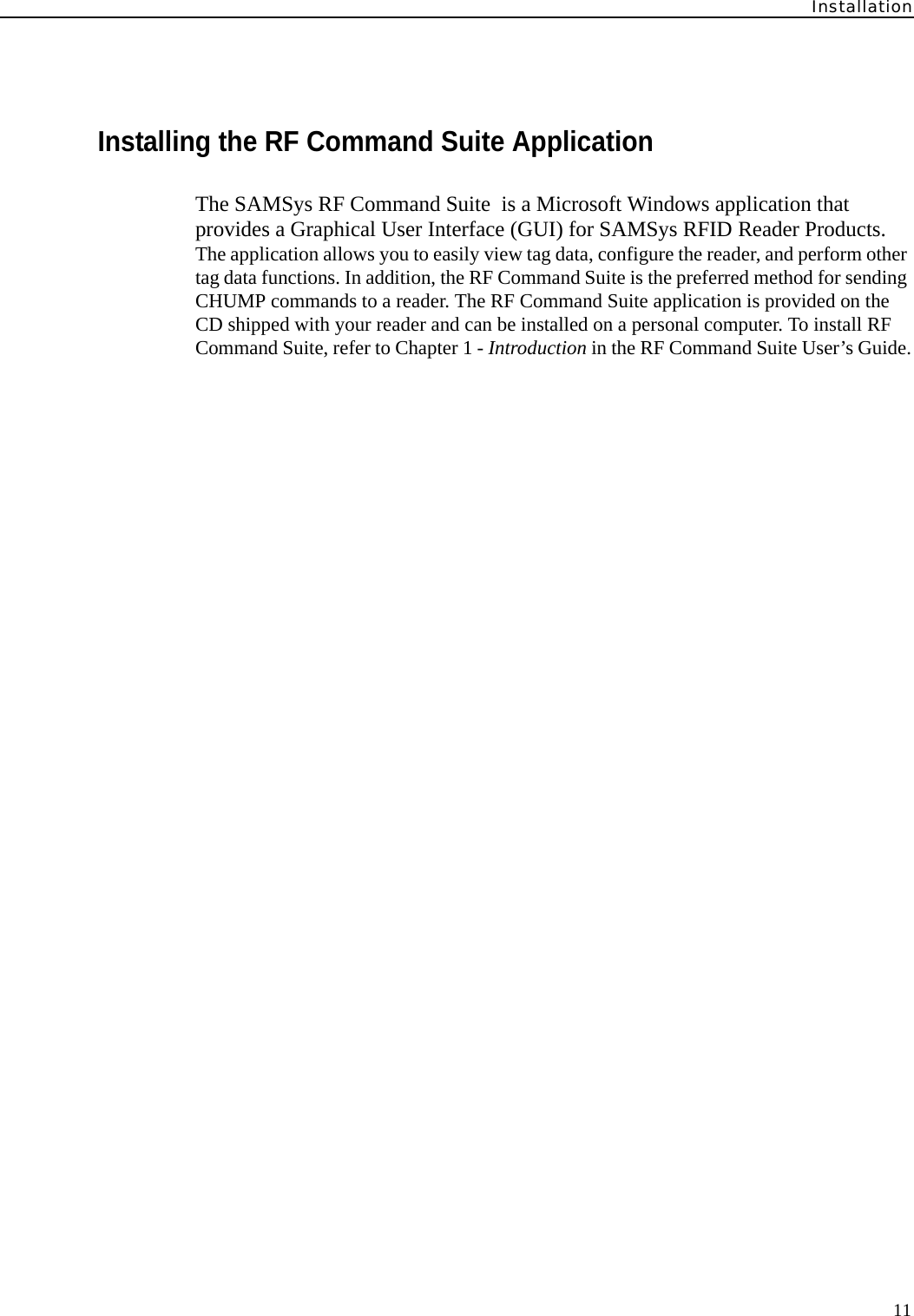
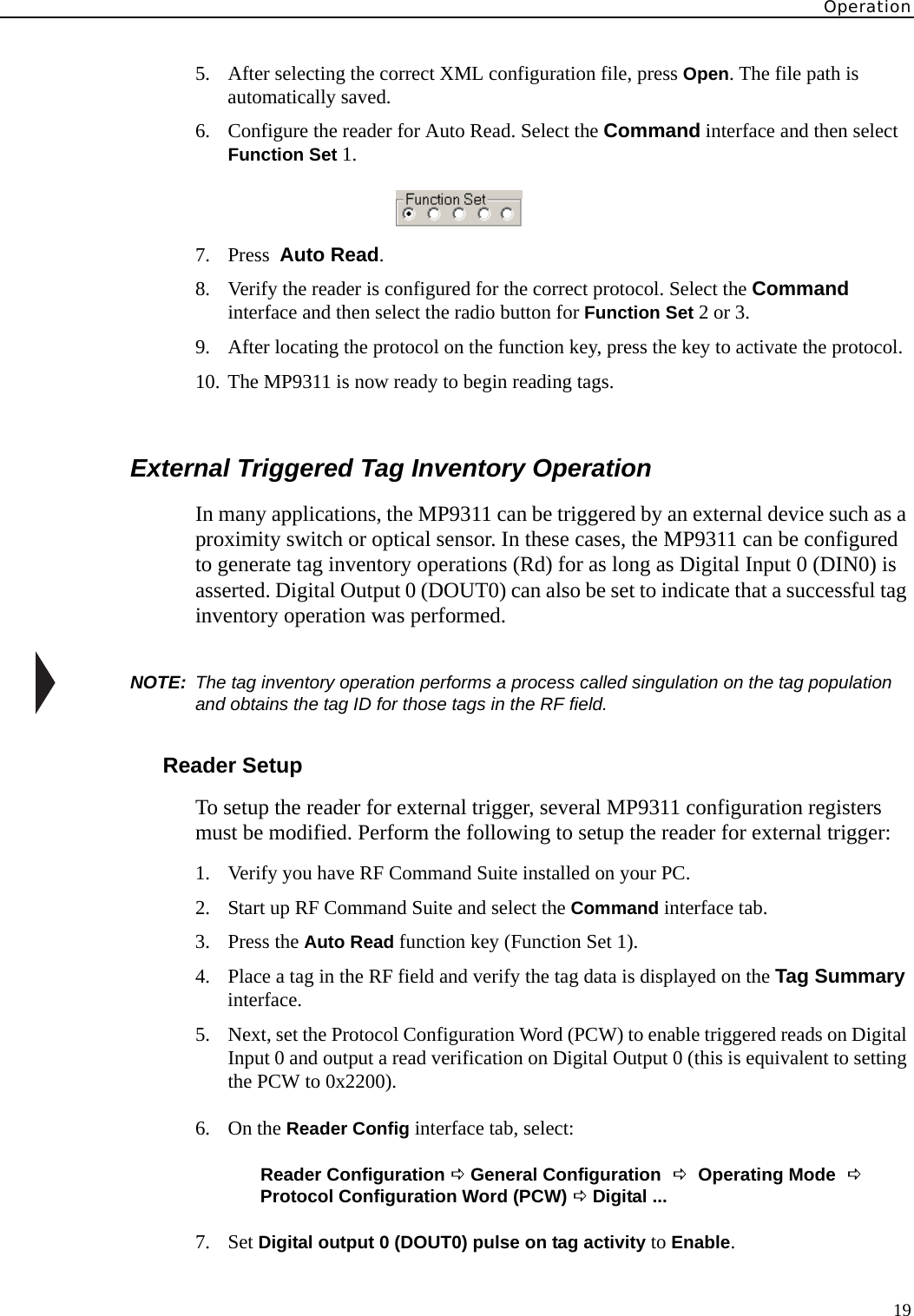
98559311 User Manual
users manual
Navigation menu
Upload a User Manual
Namespaces
Wiki Guide
HTML
PDF
Info
Views
User Manual
Discussion / Help
Navigation

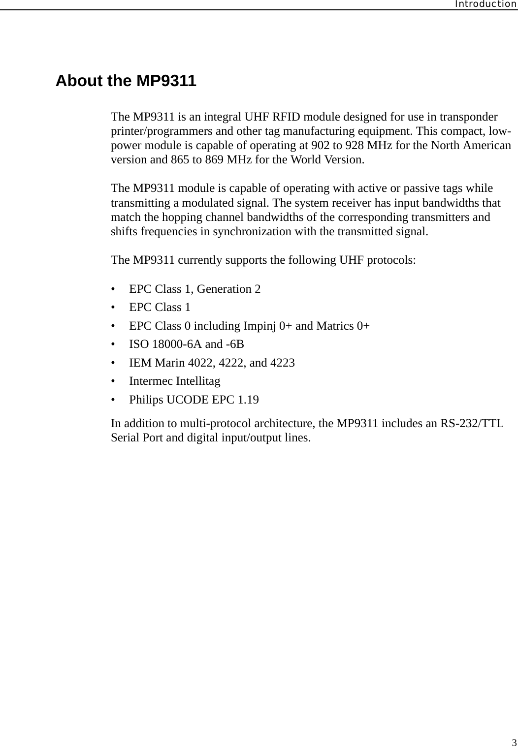

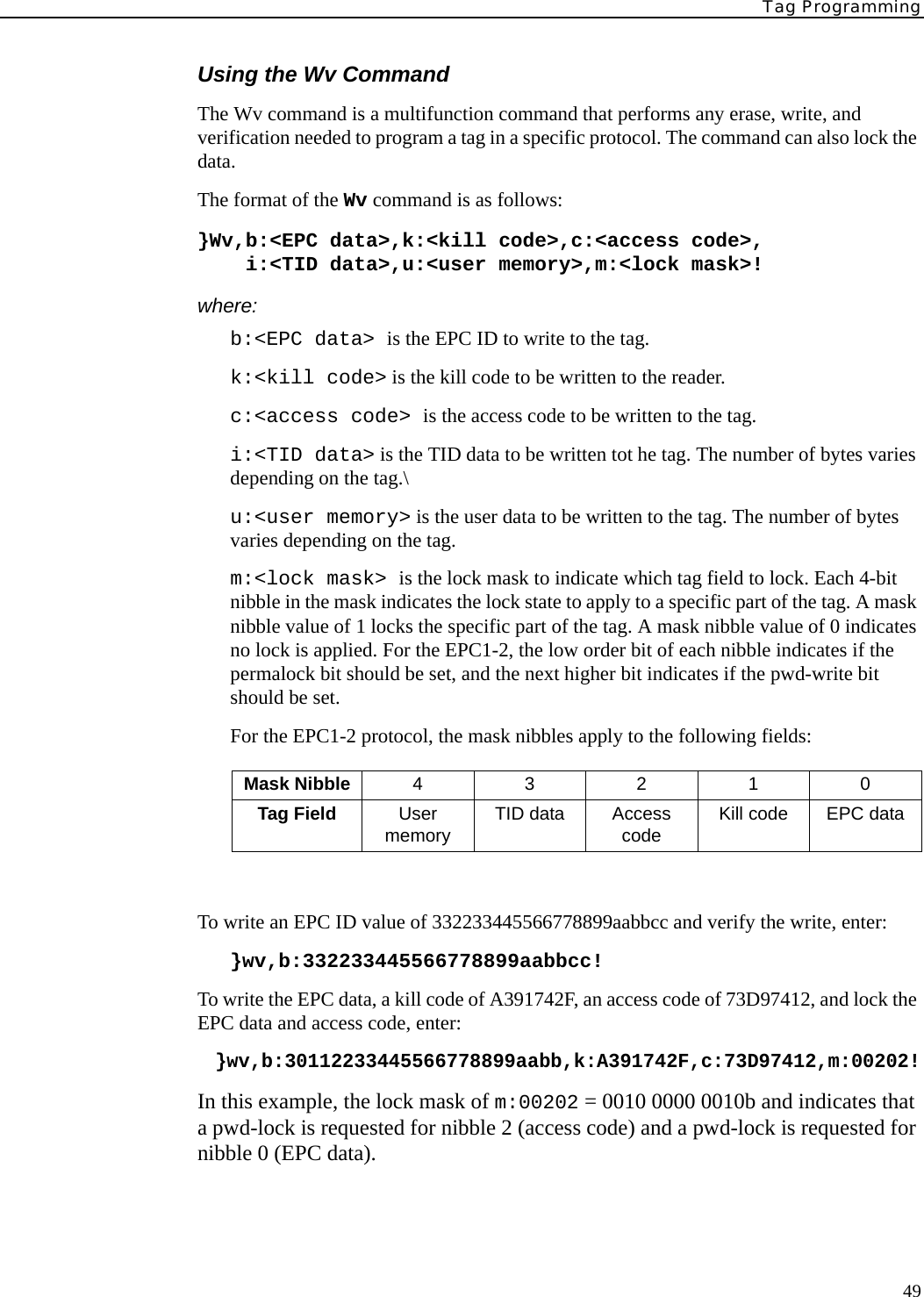
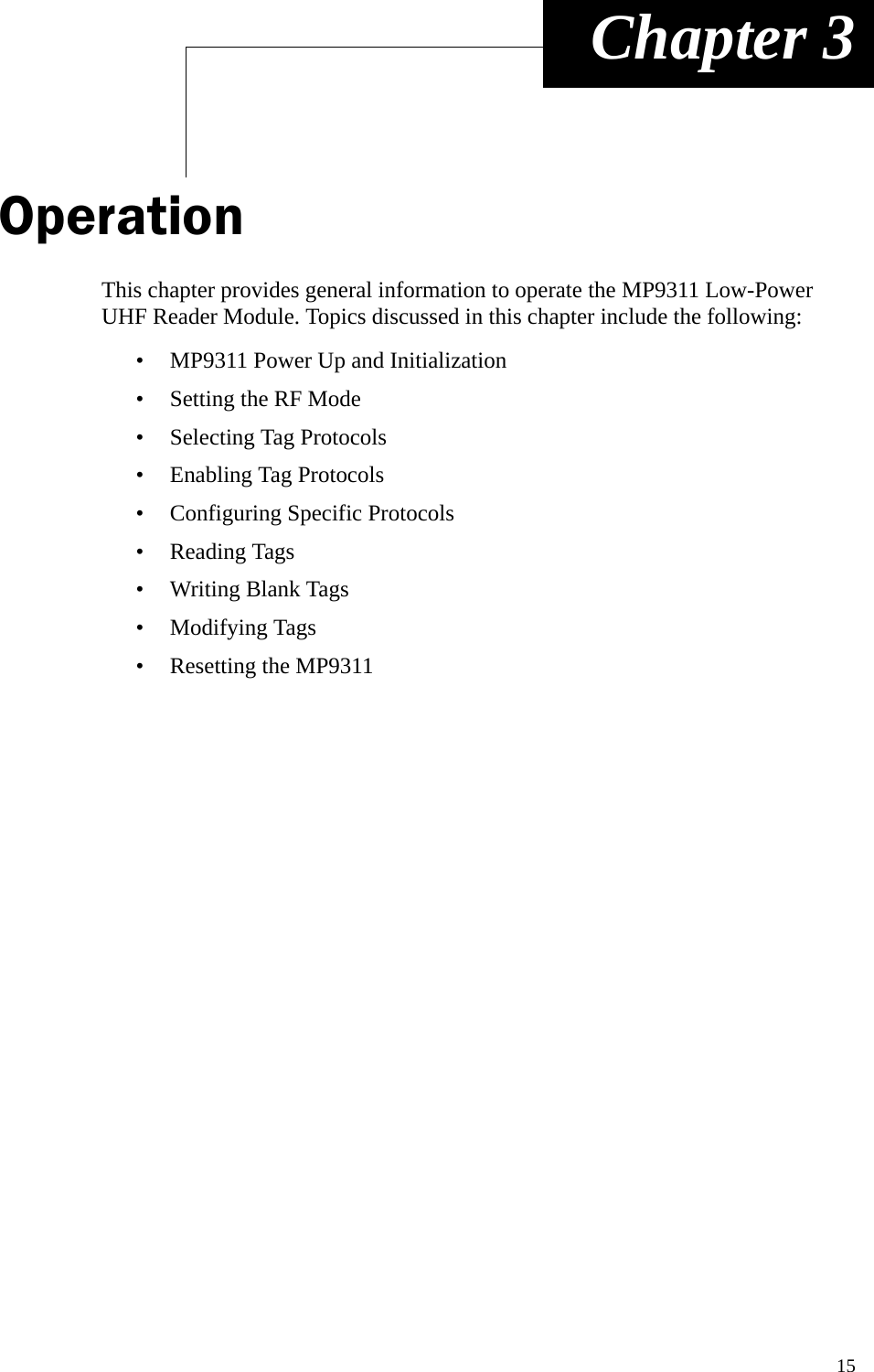
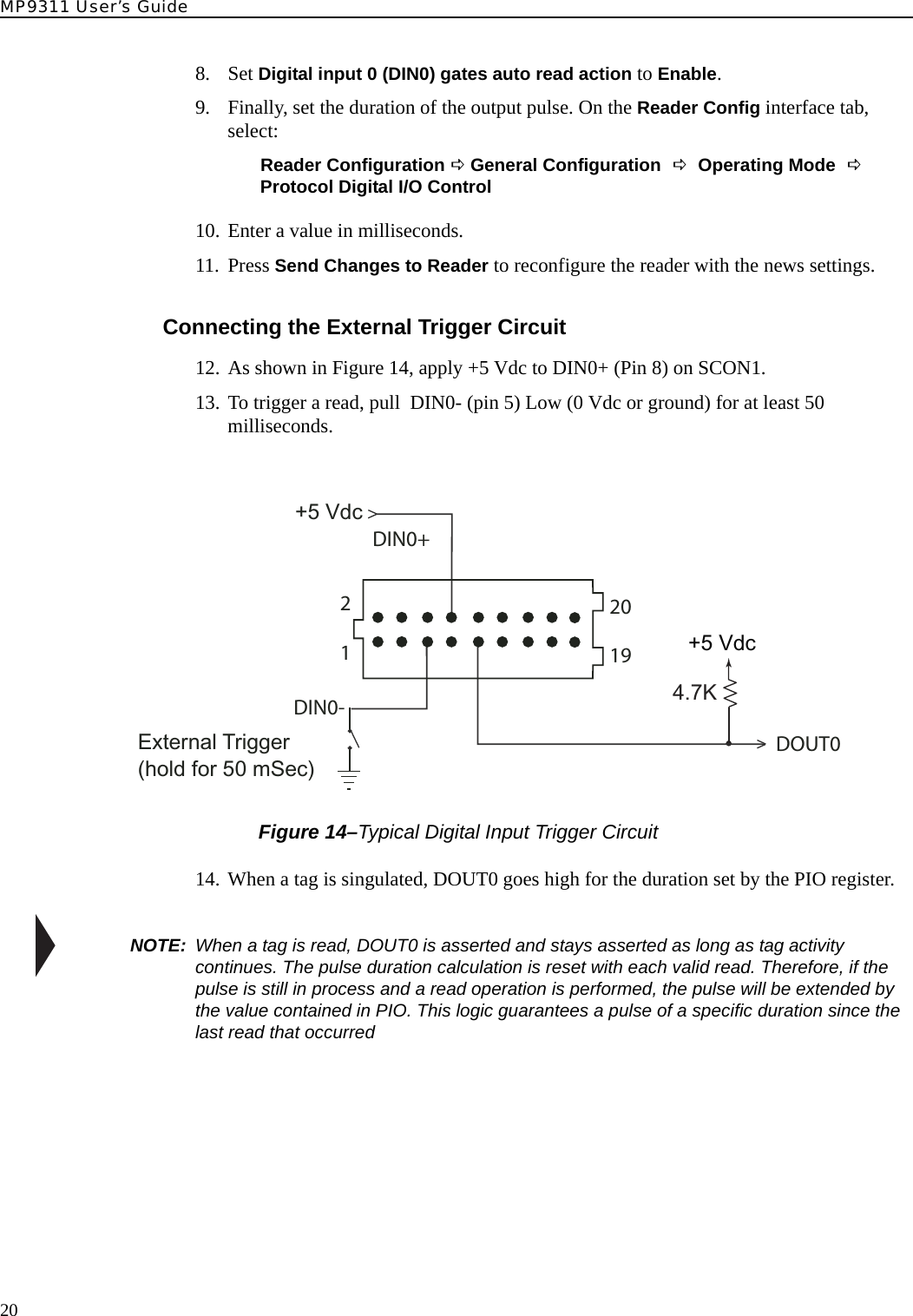
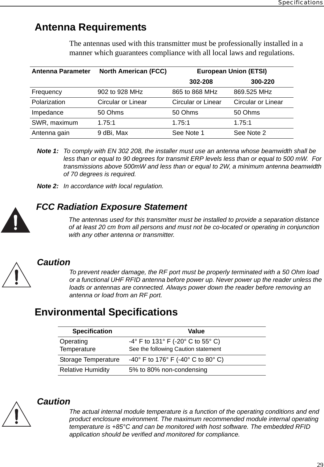
![MP9311 User’s Guide6Reader Electrical InstallationAs shown in Figure 3, the MP9311 is equipped with a keyed 20-post header (2x10), 1.0 mm pitch, .0.2 mm square pin for power, ground, and communication connections. The antenna connection is provided by a right-angle MMCX connector. Figure 3–MP9311 System ConnectorPin No. Name Signal/Value16, 18, 20 PWR System Supply Voltage, 5.0 Vdc +/-10%, 2.0A Max (All inputs tied together)3,10,12,14,17, 19 GND Ground (All grounds tied together)Pin 1 V33 3.3 Vdc Output (For factory use only.)Pin 2 PROG Program Enable (For factory use only.)Pin 4 RESET Active Low ResetPin 5 DIN0- Digital Input 0 – low input (see Note 1)Pin 6 DIN1+ Digital Input 1 – high (reference) input (see Note 1)Pin 7 DIN1- Digital Input 1 – low input (see Note 1)Pin 8 DIN0+ Digital Input 0 – high (reference) input (see Note 1)Pin 9 DOUT0 Digital output 0, open collector to ground (50 Vdc @ 40 mA max) Pin 11 DOUT1 Digital output 1, open collector to ground (50 Vdc @ 40 mA max) Pin 13 TXD TransmitPin 15 RXD ReceiveNOTE 1:To activate the digital input:3 Vdc < (VDINn+ – VDINn-) < 25 VdcOtherwise:(VDINn+ – VDINn-) ~ 0 VdcSystem Connector [SCON1]121920121920](https://usermanual.wiki/Avery-Dennison-Retail-Information-Services/98559311/User-Guide-589851-Page-14.png)
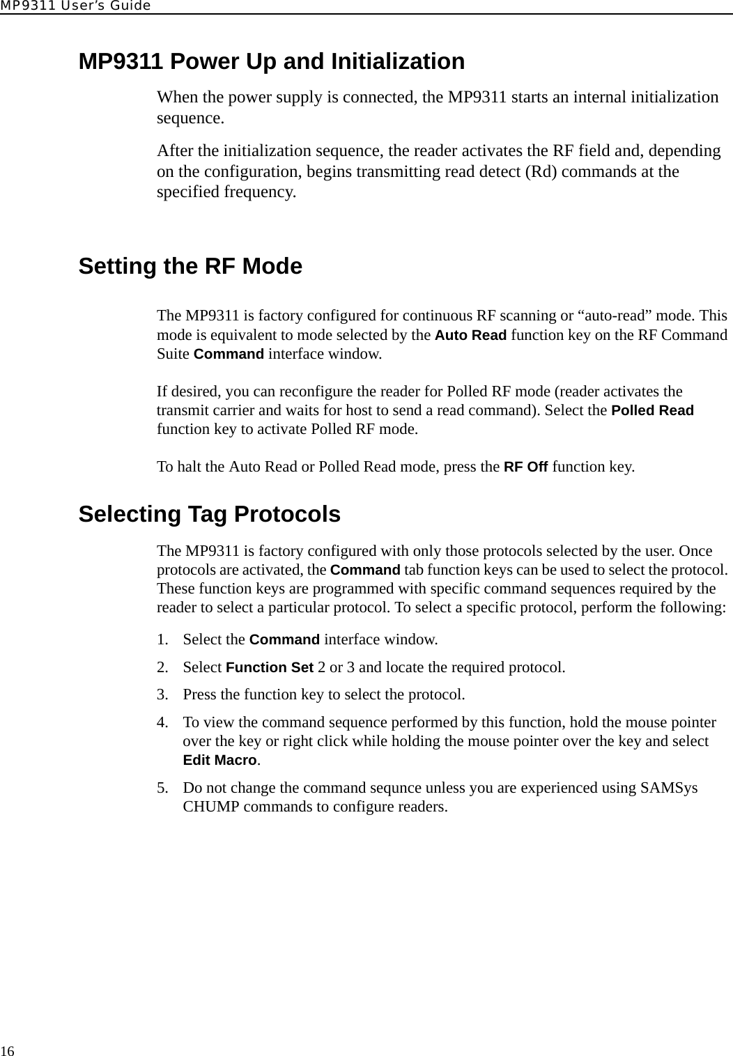


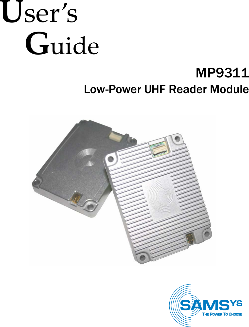
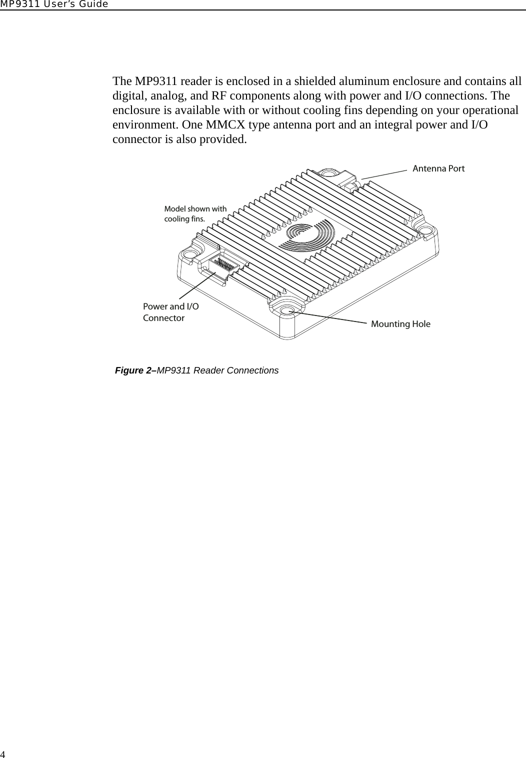
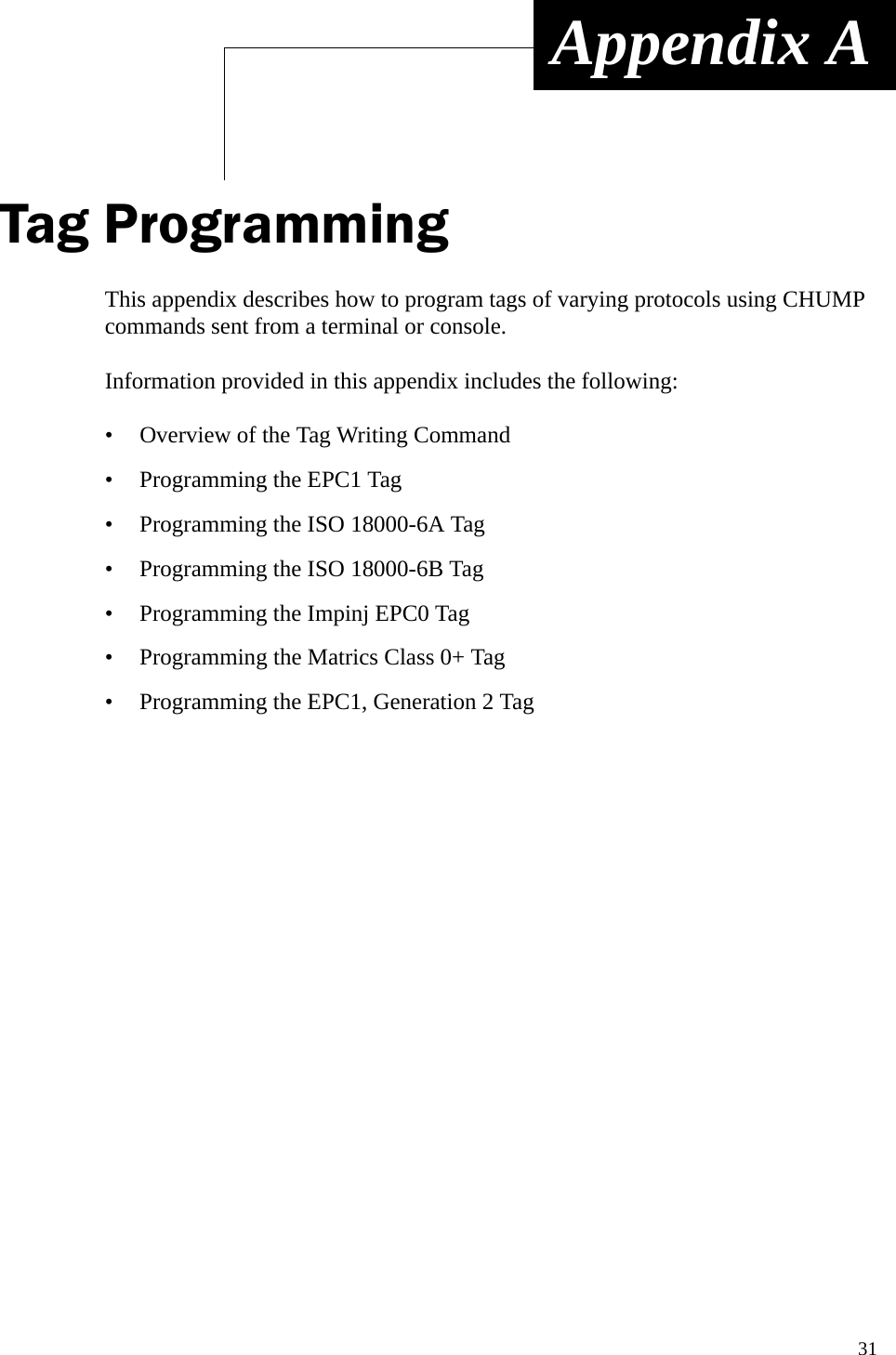
![MP9311 User’s Guide30Power and Input/Output ConnectorSystem Connector (SCON1) SpecificationsConnector Type Specification20-Pin Dual Row 2 x 10 Header, (2x10), 1.0 mm pitch, .0.2 mm square pinPin No. Name Signal/Value16, 18, 20 PWR System Supply Voltage, 5.0 Vdc +/-10%, 2.3A Max (All inputs tied together)3,10,12,14,17,19 GND Ground (All grounds tied together)Pin 1 V33 3.3 Vdc Output (For factory use only.)Pin 2 PROG Program Enable (For factory use only.)Pin 4 RESET Active Low ResetPin 5 DIN0- Digital Input 0 – low input (see Note 1)Pin 6 DIN1+ Digital Input 1 – high (reference) input (see Note 1)Pin 7 DIN1- Digital Input 1 – low input (see Note 1)Pin 8 DIN0+ Digital Input 0 – high (reference) input (see Note 1)Pin 9 DOUT0 Digital output 0, open collector to ground (50 Vdc @ 40 mA max) Pin 11 DOUT1 Digital output 1, open collector to ground (50 Vdc @ 40 mA max) Pin 13 TXD TransmitPin 15 RXD ReceiveNOTE 1:To activate the digital input:3 Vdc < (VDINn+ – VDINn-) < 25 VdcOtherwise:(VDINn+ – VDINn-) ~ 0 VdcSystem Connector [SCON1]121920121920](https://usermanual.wiki/Avery-Dennison-Retail-Information-Services/98559311/User-Guide-589851-Page-38.png)
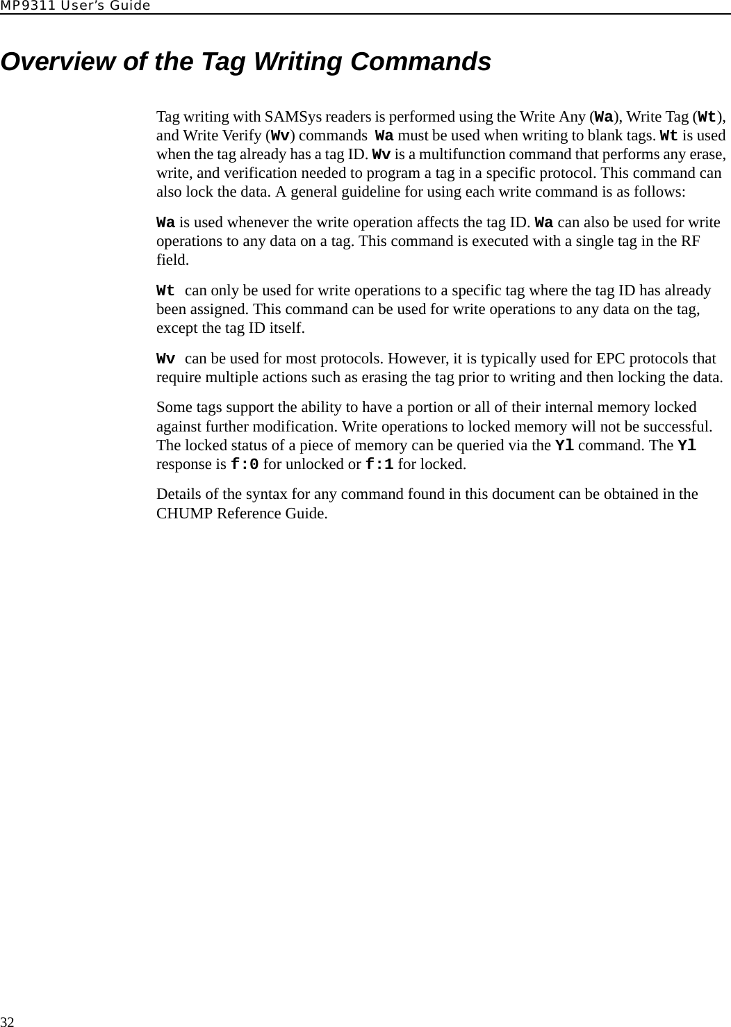
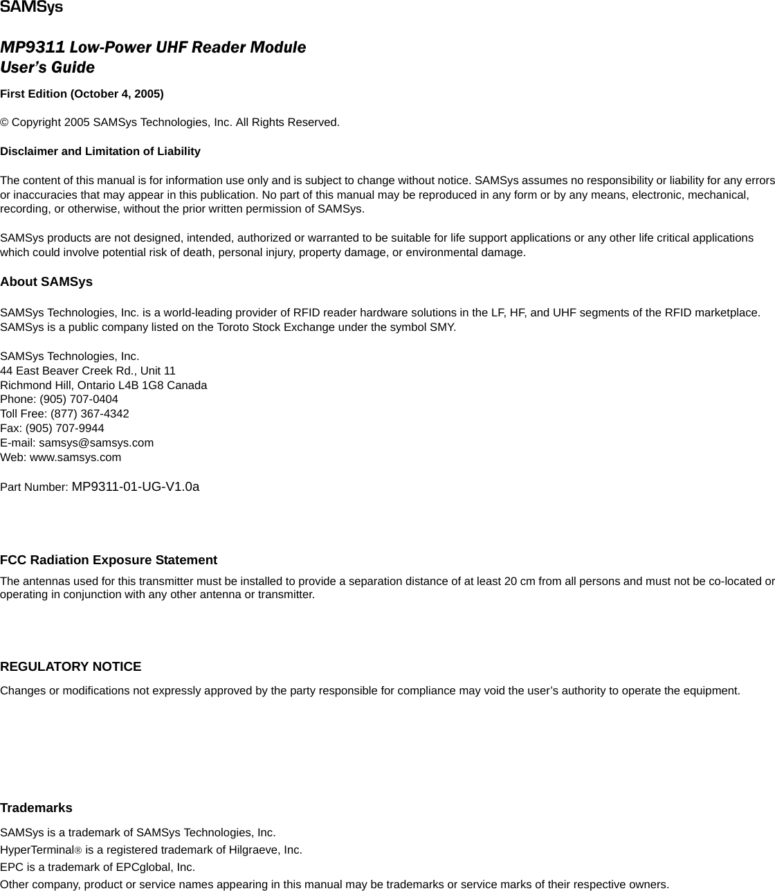
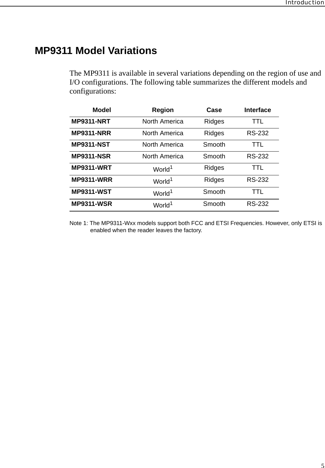
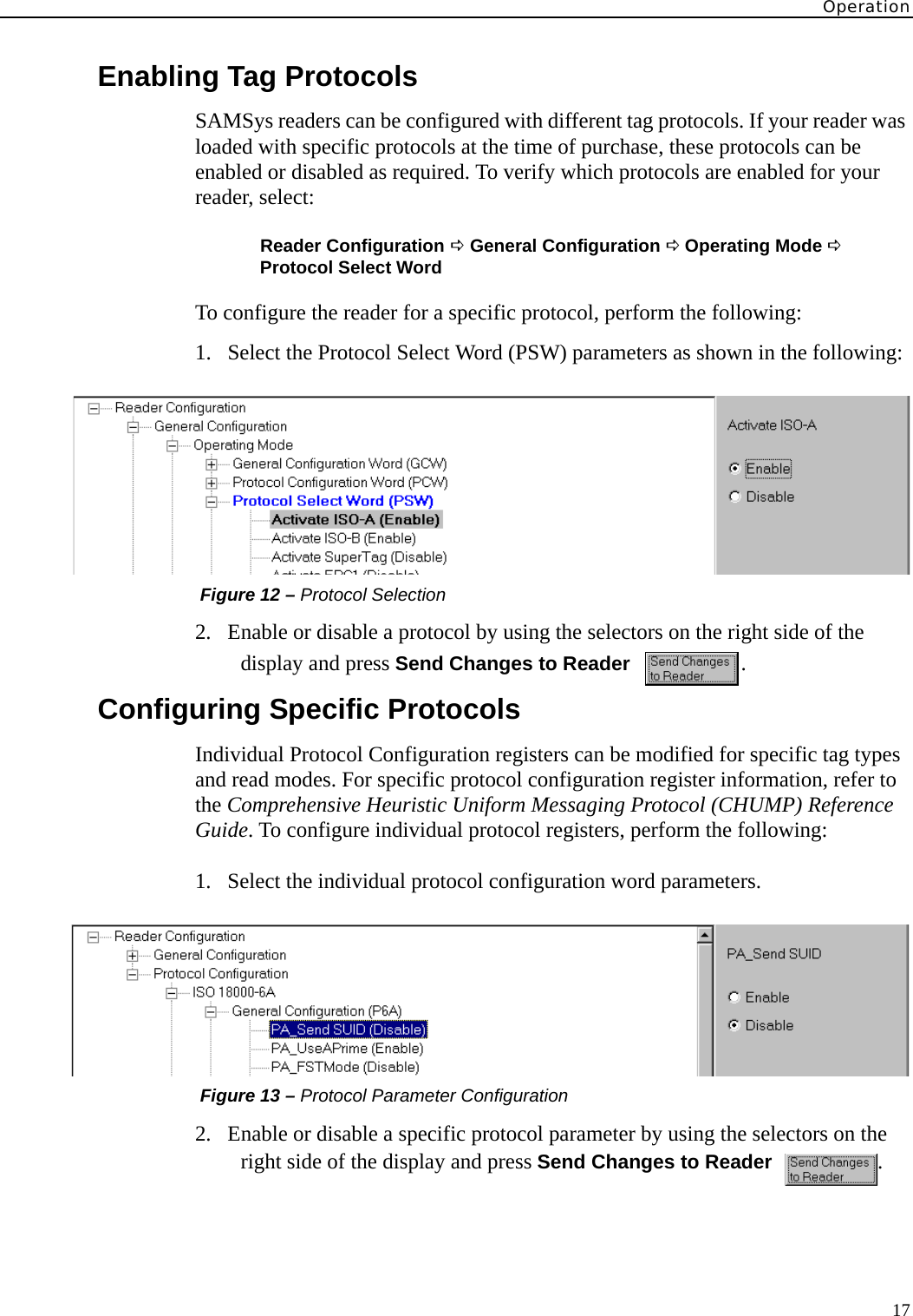
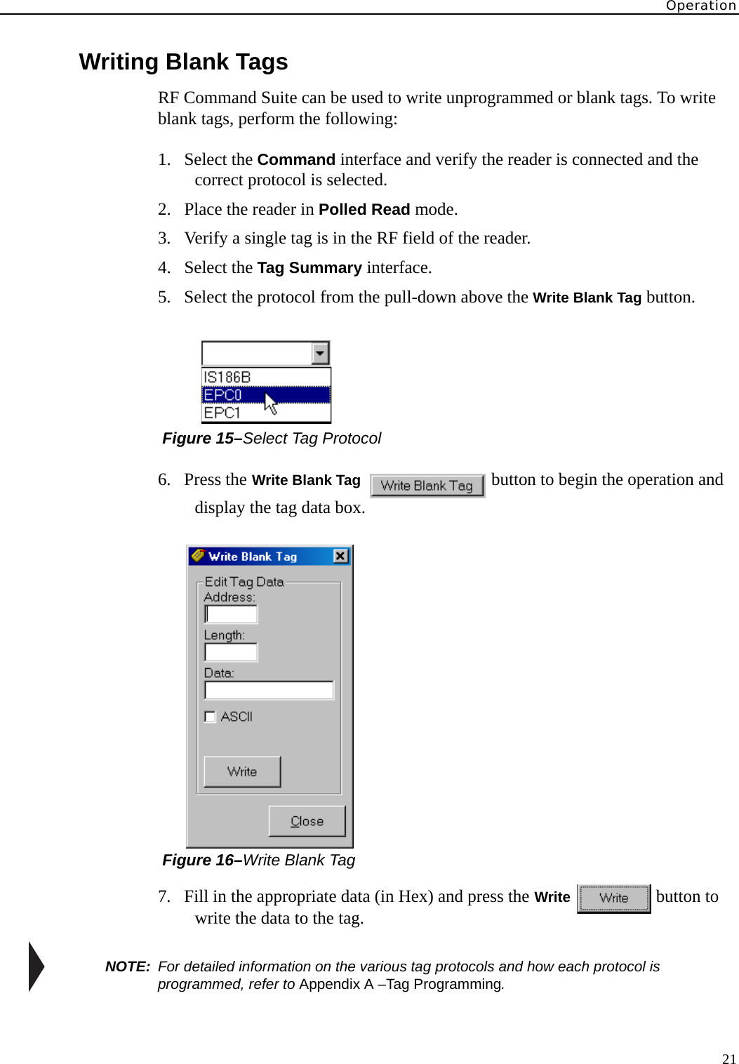
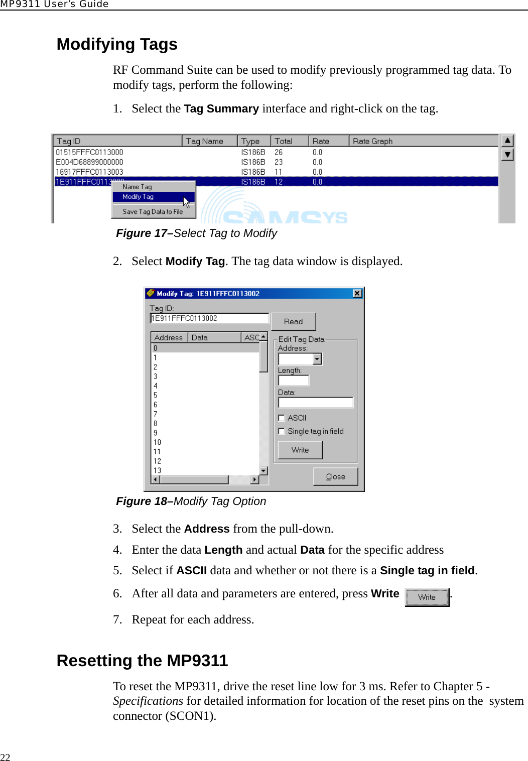
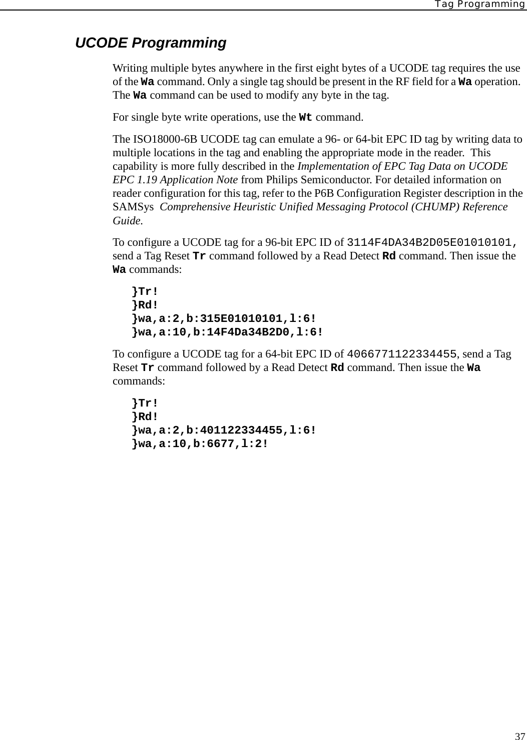
![Tag Programming33Programming the EPC1 TagSAMSys UHF readers can be used to program 64-bit and 96-bit EPC1 tags.Both the Wa and Wv command can be used with the EPC1 (Alien) tags. The Wv command is discussed at the end of this section.Do not use Wt since the tag does not support singulated write operations. Prior to writing, EPC1 tags must be erased. The Wv command and the Wa with the f:3 option will perform the erase action during command execution. If the command specified does not erase the tag during the command execution, then specify the erase operation separately using the Tag Erase (Te) command. Also, in order to calculate the CRC, the entire tag ID must be presented to the reader in one command. EPC1 tags contain an internal CRC value which covers the EPC ID and the kill passcode. The reader always calculates the CRC and writes the correct value to the tag during the write operation. As a result, the entire tag ID and passcode must be presented to the reader in one command. The last byte of the blk data passed in the Wa command is the kill passcode. In the examples that follow, this passcode is set to 00.The format of the Wa command is as follows:}Wa,a:<blk addr>,b:<blk data>[,l:<# blks>][,f:<control flag>]!where:a:<blk addr>. This parameter is optional since there is only a single writeable piece of memory. If specified, the parameter should use block address 0x00.l:<# blks>. This parameter reflects the number of bytes being written and should be equal to 9 if writing a 64-bit EPC ID with the kill passcode or equal to d if writing a 96-bit EPC ID with the kill passcode. If you are not specifying the kill code, the values should be 8 and C, respectively.b:<blk data>. This parameter must contain the entire EPC ID (64- or 96-bit), followed by the one byte kill passcode.f:<control flag>. This parameter controls operations related to writing a tag. Set f:1 to verify the data in the tag following the write operation. Set f:2 to erase the data prior to the write operation. For most applications, set both of these bits with f:3.The following is a typical command to write a 96-bit EPC1 ID tag:}wa,a:0,b:80020304050607090a0b0c0e00,l:d,f:3!The following is a typical command to write a 64-bit EPC1 ID tag:}wa,a:0,b:800080042504600200,l:9,f:3!](https://usermanual.wiki/Avery-Dennison-Retail-Information-Services/98559311/User-Guide-589851-Page-41.png)
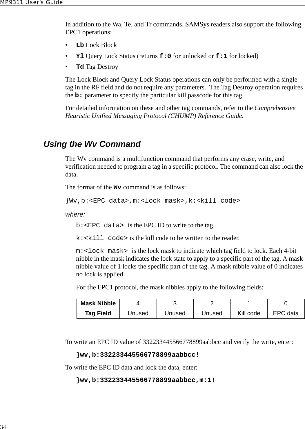
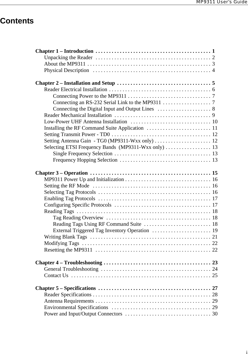
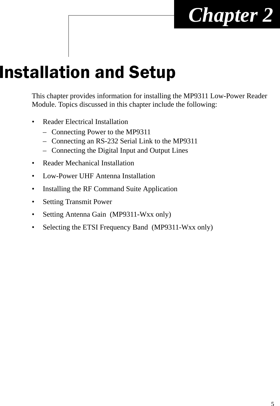
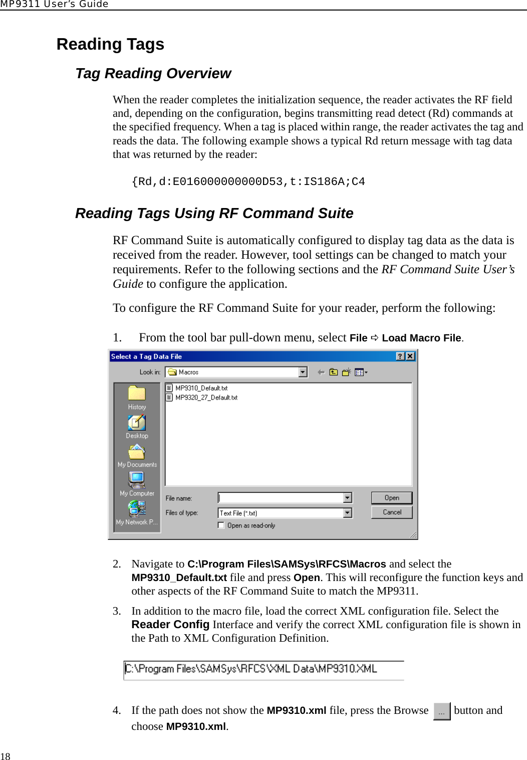
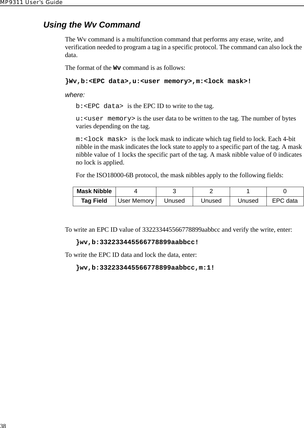
![Tag Programming35Programming the ISO18000-6A TagBoth the Wa and Wt command can be used with the ISO18000-6A tag. In addition to Wa and Wt, two additional commands can modify specific data in the tag. The Wd command modifies the DSFID and Wf modifies the AFI.Typically, the Wt command is used to modify user data in the tag. The Wt, Wd, and Wf commands require the tag ID to be in the d: parameter. Also, the tag must first be put in the SELECT state using the Ts command with the tag ID specified in the d: parameter. NOTE: Some varieties of ISO18000-6A tags are not writeable. Check with your tag vendor to verify if your tag supports write operations.The format of the Wa command is as follows:}Wa,a:<blk addr>,b:<blk data>[,l:<# blks>]!where:a:<blk addr>. In ISO18000-6A, only a single block can be written at one time and this parameter represents the specific four byte block.l:<# blks>. This parameter is optional since each write operation must contain exactly four bytes.b:<blk data>. This parameter must contain four bytes of data.The following is a typical command to write to an ISO18000-6A tag:}wa,a:0,b:01020304!For example, to write AABBCCDD to address 0x20 on a tag with ID E00300001122334455667788, issue the following command:}wt,d:E00300001122334455667788,a:20,b:AABBCCDD!In addition to the Wa, Wt, Wd, and Wf commands, SAMSys readers also support the following EPC1 operations:•Lb Lock Block•Yl Query Lock Status (returns f:0 for unlocked or f:1 for locked)Each of these operations must specify a particular tag ID using the d: parameter or first be put in the SELECT state using the Ts command with tag ID specified in the d: parameter.](https://usermanual.wiki/Avery-Dennison-Retail-Information-Services/98559311/User-Guide-589851-Page-43.png)
![MP9311 User’s Guide36Programming the ISO18000-6B TagIn ISO18000-6B, operations are controlled by a state machine within the tag. As a result, the tag must be in the Data Exchange state for the write operation to succeed. To guarantee the tag is in that state, the tag must be reset using the Tag Reset Tr command followed by a Read Detect Rd command prior to performing the first write operation.The ISO18000-6B protocol does not provide any feedback on a global write operation and the reader always provides an Ack ({A) after the tag receives a Wa command. The only way to verify success is to read the data back from the tag.An ISO18000-6B tag write operation can fail if any byte within the addressed range is locked or if the power setting is not correct. It is not uncommon for Philips and Rafsec ISO18000-6B tags to have a portion of the first eight bytes locked. Confirm the status of the specific type of tag in use.The Wa, Wt and Wv commands can be used with the ISO18000-B tag. The Wt command is used to modify data outside of the first 8 bytes in the tag and requires specification of the tag ID using the d:parameter. The Wv command is discussed at the end of this section.The format of the Wa command is as follows:}Wa,a:<blk addr>,b:<blk data>[,l:<# blks>]!where:a:<blk addr>. In ISO18000-6B, this parameter provides the address of the writeable memory block. The block size is one byte.l:<# blks>. This parameter reflects the number of blocks being written (which is equal to the number of bytes in this case).b:<blk data>. This parameter contains the actual data being written.The following command example command writes AABBCCDD to user memory at address 0x20 on a tag with ID EF04001122334455:}wt,d:EF04001122334455,a:20,b:AABBCCDD,l:4!In addition to the Wa and Wt commands, SAMSys readers also support the following ISO18000-6B operations:•Lb Lock Block•Yl Query Lock Status (returns f:0 for unlocked or f:1 for locked)Each of these operations must specify a particular tag ID with the d: parameter and block address with the a: parameter.](https://usermanual.wiki/Avery-Dennison-Retail-Information-Services/98559311/User-Guide-589851-Page-44.png)
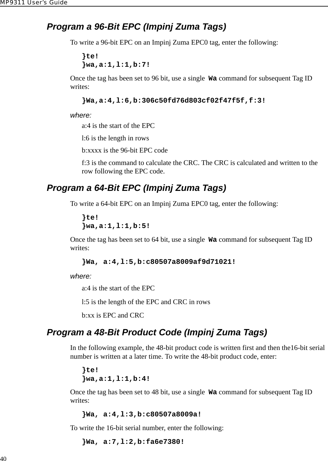
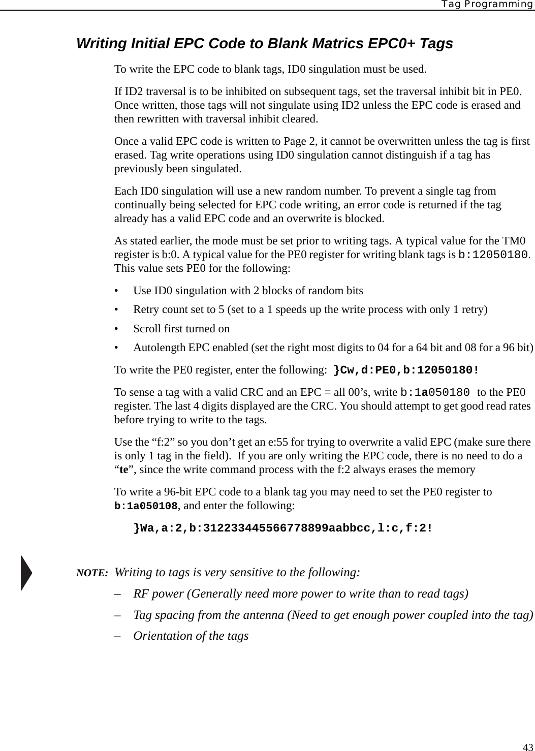
![Tag Programming39Programming the Impinj EPC0 TagIn EPC0, there is no single standard for performing write operations and there are noteable differences between manufacturers. Some varieties of EPC0 tags are not writeable. This section addresses writable EPC0 tags produced by Impinj.The Wa, Wt and Wv commands can be used to write EPC0 tags. The Wv command is discussed at the end of this section.The format of the Wa command is as follows:}Wa,a:<blk addr>,b:<blk data>[,l:<# blks>][,d:<tag ID>]!where:a:<blk addr>. This parameter provides the address of a writeable memory block. The block size is one row which is two bytes. The Control Word (a:1) must be written for the desired EPC ID length.l:<# blks>. This parameter is required and is the number of bytes being written.b:<blk data>. This parameter is required and contains the data to write.d:<tag ID> . This parameter is required for the Wt command (optional for Wa) and specifies the EPC code of the tag to which the write operation applies. Typically, the Wt command would be used to modify user data in the tag. The Wt command requires specification of the tag ID using the d: parameter.In addition to the Wt command, the reader also supports the following operations:•Lb Lock Block•Yl Query Lock Status (returns f:0 for unlocked or f:1 for locked)•Td Tag DestroyThe Lock Block and Query Lock Status operations must be performed with a single tag in the RF field and do not require any parameters. The Tag Destroy operation requires d: parameter to specify a particular tag ID and the b:parameter to specify the particular kill passcode for this tag.For detailed information on these and other tag commands, refer to the Comprehensive Heuristic Unified Messaging Protocol (CHUMP) Reference Guide.](https://usermanual.wiki/Avery-Dennison-Retail-Information-Services/98559311/User-Guide-589851-Page-47.png)
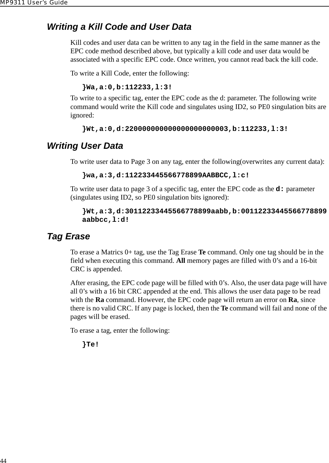
![MP9311 User’s Guide42Programming the Matrics Class 0+ TagMatrics Class 0+ tags utilize a process called Singulation. This is a process of uniquely identifying a tag in a population of tags and retieving its Electronic Product Code (EPC). For detailed information on EPC Class 0 singulation, refer to the EPC Global Class 0 specification.When a tag is requested to identify itself, it responds with different data based on its singulation mode. Class 0 and Class 0+ tags allow three modes of singulation:• ID2 - This mode responds directly with the EPC. ID2 is the fastest mode (fewest bits transmitted), but requires the reader to echo the bits back to the tag. This echo can create security issues. Also, this mode can not be read when writing the EPC, since the echo will change the EPC as you write it.• ID0 - This mode returns packets of 12 random bits that are different every time you singulate. When the reader has what it determine is the correct number, it writes the EPC. This mode is the only reliable method of singulation during writing the tag EPC.• ID1 - This mode is the same as ID0, but every singulation returns the same bit stream. The bits are random, but they are seeded from the EPC. Writing the EPC changes these bits.The singulation mode is controlled with the PE0 register and must be set prior to writing tags.Matrics Class 0+ tags contain three writable pages or memory blocks: These pages are as follows:• Page 0 – Kill code (24 bits)• Page 2 – EPC code (64 or 96 bits)• Page 3 – User data (104 bits)When Page 2 or Page 3 data is written, a 16-bit CRC is appended.The Wa, Wt and Wv commands can be used to write Matrics Class 0+ tags. The Wv command is discussed at the end of this section.The format of the Wa command is as follows:}Wa,a:<blk addr>,b:<blk data>[,l:<# blks>][,d:<tag ID>]!where:a:<blk addr>. This represents the memory page of the tag on which the write operation will occur. Values can be 0, 2 or 3, as defined previously. If this parameter is missing, it will default to 0.l:<# blks>. This parameter is required and is the number of bytes being written.b:<blk data>. This parameter is required and contains the data to write.d:<tag ID> . This parameter is required for the Wt command (optional for Wa) and specifies the EPC code of the tag to which the write operation applies.](https://usermanual.wiki/Avery-Dennison-Retail-Information-Services/98559311/User-Guide-589851-Page-50.png)
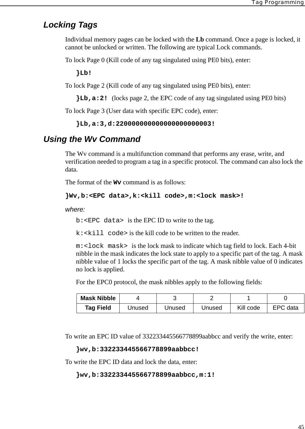
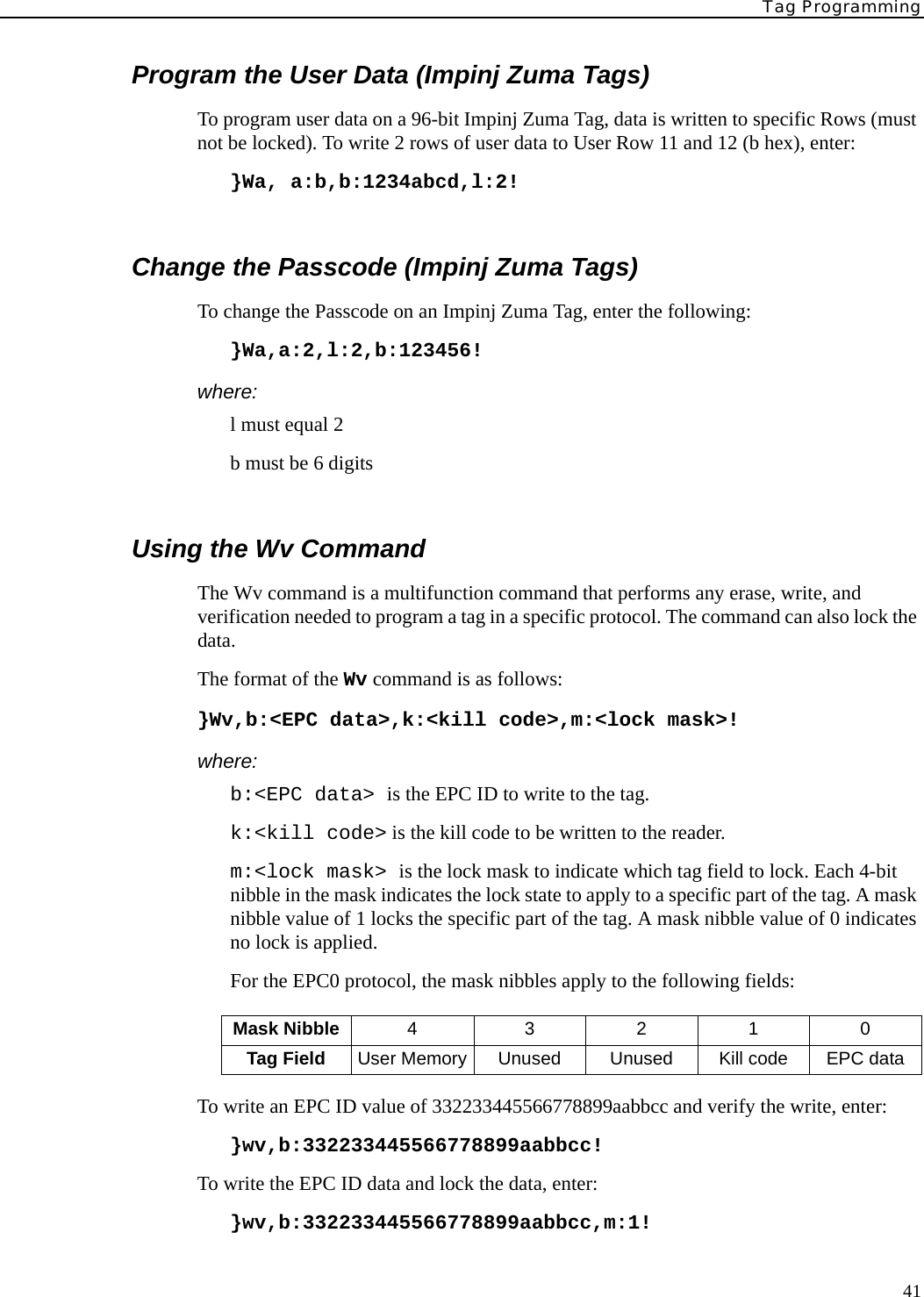
![Tag Programming47Writing the TagThree CHUMP commands can be used to write to an EPC1, Gen2 tag: Wa, Wt, and Wv. Wa writes to any tag in the field and is typically used to write the EPC ID to tag. Wt writes to a specific tag, as defined in the input parameter list, and is typically used to write to user data on a tag. Wv is a multifunction command that erases, writes, and verifies a tag.Using the Wa CommandThe format of the Wa command is as follows:}Wa,a:<blk addr>,b:<blk data>[,l:<# blks>][,s:<offset>] [,f:<xxx>]!where:a:<blk addr> is the block address (0 by default). For EPC1, Gen2 0=Reserved,1=EPC, 2=TID, 3=USER memory bankb:<blk data> is the block data to write. Must be 16-word multiple.l:<# blks> is the length in 16-bit words. Defaults to length of data if missing.s:<offset> is the offset to start the write (EPC1, Gen2 only). Defaults to 0 if.f:<xxx> is protocol specific flag data. Set f=1 for read back/verify. EPC1, Gen2 tags provide SUCCESS/FAIL feedback. Defaults to 0.To write an EPC ID value of 332233445566778899aabbcc onto a tag with the Protocol Control field set for a 96 bit tag, enter:}wa,a:1,s:2,b:332233445566778899aabbcc! To add the length field, enter:}wa,a:1,s:2,b:332233445566778899aabbcc,l:6! To request a read/verify cycle following the write operation, enter:}wa,a:1,s:2,b:332233445566778899aabbcc,l:6,f:1! In order to write an EPC ID to a blank tag, the Protocol Control bits must also be set. This can be accomplished in a single write command since the Protocol Control bits are contained in the same memory bank as the EPC ID. Following the previous example, the command would include setting the Protocol Control to 3000 as follows:}wa,a:1,s:1,b:3000332233445566778899aabbcc!The Kill and Access Passwords are contained in the Reserved Memory bank. Each password can be written with separate Wa commands or a single command:To write a 32-bit Access password at offset 2, enter:}wa,a:0,s:2,b:55667788!To write both Access passwords with a single command, enter:}wa,a:0,b:3322334455667788!](https://usermanual.wiki/Avery-Dennison-Retail-Information-Services/98559311/User-Guide-589851-Page-55.png)
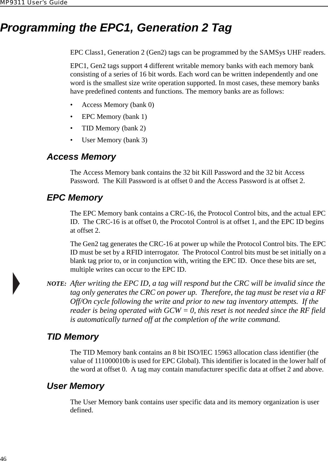
![MP9311 User’s Guide48Using the Wt CommandThe Wt command can also be used to write the Kill and Access passwords and the TID and User Memory banks. The Wt command requires the use of the EPC ID of the tag.The format of the Wt command is as follows:}Wt, b:<data> ,d:<tag id> a:<block address >[,l:<length>] [,s:<offset>][, f:<flags>]! where:a:<block address> is the block address (0 by default). For EPC1, Gen2 0=Reserved,1=EPC, 2=TID, 3=USER memory bankb:<blk data> is the block data to write. Must be 16-word multiple.d:<tag ID> is the tag identification.l:<# blks> is the length in 16-bit words. Defaults to length of data if missing.s:<offset> is the offset to start write (EPC1, Gen2 only). Defaults to 0 if missing.f:<xxx> is protocol specific flag data. Set f=1 for read back/verify. EPC1, Gen2 tags provide SUCCESS/FAIL feedback. Defaults to 0.To write the Kill password to a tag with EPC ID= 332233445566778899aabbcc, enter:}wt,d:332233445566778899aabbcc,a:0,b:33223344!](https://usermanual.wiki/Avery-Dennison-Retail-Information-Services/98559311/User-Guide-589851-Page-56.png)