Avery Dennison Retail Information Services 98559311 RFID Reader Module User Manual om v100 hi469311 0000
Avery Dennison Retail Information Services, LLC RFID Reader Module om v100 hi469311 0000
users manual
User’s
Guide
MP9311
Low-Power UHF Reader Module
THE POWER TOCHOOSE
SAMSys
MP9311 Low-Power UHF Reader Module
User’s Guide
First Edition (October 4, 2005)
© Copyright 2005 SAMSys Technologies, Inc. All Rights Reserved.
Disclaimer and Limitation of Liability
The content of this manual is for information use only and is subject to change without notice. SAMSys assumes no responsibility or liability for any errors
or inaccuracies that may appear in this publication. No part of this manual may be reproduced in any form or by any means, electronic, mechanical,
recording, or otherwise, without the prior written permission of SAMSys.
SAMSys products are not designed, intended, authorized or warranted to be suitable for life support applications or any other life critical applications
which could involve potential risk of death, personal injury, property damage, or environmental damage.
About SAMSys
SAMSys Technologies, Inc. is a world-leading provider of RFID reader hardware solutions in the LF, HF, and UHF segments of the RFID marketplace.
SAMSys is a public company listed on the Toroto Stock Exchange under the symbol SMY.
SAMSys Technologies, Inc.
44 East Beaver Creek Rd., Unit 11
Richmond Hill, Ontario L4B 1G8 Canada
Phone: (905) 707-0404
Toll Free: (877) 367-4342
Fax: (905) 707-9944
E-mail: samsys@samsys.com
Web: www.samsys.com
Part Number: MP9311-01-UG-V1.0a
FCC Radiation Exposure Statement
The antennas used for this transmitter must be installed to provide a separation distance of at least 20 cm from all persons and must not be co-located or
operating in conjunction with any other antenna or transmitter.
REGULATORY NOTICE
Changes or modifications not expressly approved by the party responsible for compliance may void the user’s authority to operate the equipment.
Trademarks
SAMSys is a trademark of SAMSys Technologies, Inc.
HyperTerminal® is a registered trademark of Hilgraeve, Inc.
EPC is a trademark of EPCglobal, Inc.
Other company, product or service names appearing in this manual may be trademarks or service marks of their respective owners.

MP9311 User’s Guide
i
Contents
Chapter 1 – Introduction . . . . . . . . . . . . . . . . . . . . . . . . . . . . . . . . . . . . . . . . . . . 1
Unpacking the Reader . . . . . . . . . . . . . . . . . . . . . . . . . . . . . . . . . . . . . . . . . . . 2
About the MP9311 . . . . . . . . . . . . . . . . . . . . . . . . . . . . . . . . . . . . . . . . . . . . . . 3
Physical Description . . . . . . . . . . . . . . . . . . . . . . . . . . . . . . . . . . . . . . . . . . . . 4
Chapter 2 – Installation and Setup . . . . . . . . . . . . . . . . . . . . . . . . . . . . . . . . . . . 5
Reader Electrical Installation . . . . . . . . . . . . . . . . . . . . . . . . . . . . . . . . . . . . . . 6
Connecting Power to the MP9311 . . . . . . . . . . . . . . . . . . . . . . . . . . . . . . . 7
Connecting an RS-232 Serial Link to the MP9311 . . . . . . . . . . . . . . . . . . 7
Connecting the Digital Input and Output Lines . . . . . . . . . . . . . . . . . . . . 8
Reader Mechanical Installation . . . . . . . . . . . . . . . . . . . . . . . . . . . . . . . . . . . . 9
Low-Power UHF Antenna Installation . . . . . . . . . . . . . . . . . . . . . . . . . . . . . . 10
Installing the RF Command Suite Application . . . . . . . . . . . . . . . . . . . . . . . . 11
Setting Transmit Power - TD0 . . . . . . . . . . . . . . . . . . . . . . . . . . . . . . . . . . . . . 12
Setting Antenna Gain - TG0 (MP9311-Wxx only) . . . . . . . . . . . . . . . . . . . . . 12
Selecting ETSI Frequency Bands (MP9311-Wxx only) . . . . . . . . . . . . . . . . . 13
Single Frequency Selection . . . . . . . . . . . . . . . . . . . . . . . . . . . . . . . . . . . . 13
Frequency Hopping Selection . . . . . . . . . . . . . . . . . . . . . . . . . . . . . . . . . . 13
Chapter 3 – Operation . . . . . . . . . . . . . . . . . . . . . . . . . . . . . . . . . . . . . . . . . . . . . 15
MP9311 Power Up and Initialization . . . . . . . . . . . . . . . . . . . . . . . . . . . . . . . . 16
Setting the RF Mode . . . . . . . . . . . . . . . . . . . . . . . . . . . . . . . . . . . . . . . . . . . . 16
Selecting Tag Protocols . . . . . . . . . . . . . . . . . . . . . . . . . . . . . . . . . . . . . . . . . . 16
Enabling Tag Protocols . . . . . . . . . . . . . . . . . . . . . . . . . . . . . . . . . . . . . . . . . . 17
Configuring Specific Protocols . . . . . . . . . . . . . . . . . . . . . . . . . . . . . . . . . . . . 17
Reading Tags . . . . . . . . . . . . . . . . . . . . . . . . . . . . . . . . . . . . . . . . . . . . . . . . . . 18
Tag Reading Overview . . . . . . . . . . . . . . . . . . . . . . . . . . . . . . . . . . . . . . . 18
Reading Tags Using RF Command Suite . . . . . . . . . . . . . . . . . . . . . . . . . 18
External Triggered Tag Inventory Operation . . . . . . . . . . . . . . . . . . . . . . 19
Writing Blank Tags . . . . . . . . . . . . . . . . . . . . . . . . . . . . . . . . . . . . . . . . . . . . . 21
Modifying Tags . . . . . . . . . . . . . . . . . . . . . . . . . . . . . . . . . . . . . . . . . . . . . . . . 22
Resetting the MP9311 . . . . . . . . . . . . . . . . . . . . . . . . . . . . . . . . . . . . . . . . . . . 22
Chapter 4 – Troubleshooting . . . . . . . . . . . . . . . . . . . . . . . . . . . . . . . . . . . . . . . . 23
General Troubleshooting . . . . . . . . . . . . . . . . . . . . . . . . . . . . . . . . . . . . . . . . . 24
Contact Us . . . . . . . . . . . . . . . . . . . . . . . . . . . . . . . . . . . . . . . . . . . . . . . . . . . . 25
Chapter 5 – Specifications . . . . . . . . . . . . . . . . . . . . . . . . . . . . . . . . . . . . . . . . . . 27
Reader Specifications . . . . . . . . . . . . . . . . . . . . . . . . . . . . . . . . . . . . . . . . . . . . 28
Antenna Requirements . . . . . . . . . . . . . . . . . . . . . . . . . . . . . . . . . . . . . . . . . . . 29
Environmental Specifications . . . . . . . . . . . . . . . . . . . . . . . . . . . . . . . . . . . . . 29
Power and Input/Output Connectors . . . . . . . . . . . . . . . . . . . . . . . . . . . . . . . . 30

MP9311 User’s Guide
ii
Appendix A – Tag Programming . . . . . . . . . . . . . . . . . . . . . . . . . . . . . . . . . . . . 31
Overview of the Tag Writing Commands . . . . . . . . . . . . . . . . . . . . . . . . . . . . 32
Programming the EPC1 Tag . . . . . . . . . . . . . . . . . . . . . . . . . . . . . . . . . . . . . . 33
Programming the ISO18000-6A Tag . . . . . . . . . . . . . . . . . . . . . . . . . . . . . . . . 35
Programming the ISO18000-6B Tag . . . . . . . . . . . . . . . . . . . . . . . . . . . . . . . . 36
UCODE Programming . . . . . . . . . . . . . . . . . . . . . . . . . . . . . . . . . . . . . . . 37
Using the Wv Command . . . . . . . . . . . . . . . . . . . . . . . . . . . . . . . . . . . . . . 38
Programming the Impinj EPC0 Tag . . . . . . . . . . . . . . . . . . . . . . . . . . . . . . . . . 39
Program a 96-Bit EPC (Impinj Zuma Tags) . . . . . . . . . . . . . . . . . . . . . . . 40
Program a 64-Bit EPC (Impinj Zuma Tags) . . . . . . . . . . . . . . . . . . . . . . . 40
Program a 48-Bit Product Code (Impinj Zuma Tags) . . . . . . . . . . . . . . . . 40
Program the User Data (Impinj Zuma Tags) . . . . . . . . . . . . . . . . . . . . . . . 41
Change the Passcode (Impinj Zuma Tags) . . . . . . . . . . . . . . . . . . . . . . . . 41
Using the Wv Command . . . . . . . . . . . . . . . . . . . . . . . . . . . . . . . . . . . . . . 41
Programming the Matrics Class 0+ Tag . . . . . . . . . . . . . . . . . . . . . . . . . . . . . 42
Writing Initial EPC Code to Blank Matrics EPC0+ Tags . . . . . . . . . . . . . 43
Writing a Kill Code and User Data . . . . . . . . . . . . . . . . . . . . . . . . . . . . . . 44
Writing User Data . . . . . . . . . . . . . . . . . . . . . . . . . . . . . . . . . . . . . . . . . . . 44
Tag Erase . . . . . . . . . . . . . . . . . . . . . . . . . . . . . . . . . . . . . . . . . . . . . . . . . . 44
Locking Tags . . . . . . . . . . . . . . . . . . . . . . . . . . . . . . . . . . . . . . . . . . . . . . . 45
Using the Wv Command . . . . . . . . . . . . . . . . . . . . . . . . . . . . . . . . . . . . . . 45
Programming the EPC1, Generation 2 Tag . . . . . . . . . . . . . . . . . . . . . . . . . . . 46
Access Memory . . . . . . . . . . . . . . . . . . . . . . . . . . . . . . . . . . . . . . . . . . . . . 46
EPC Memory . . . . . . . . . . . . . . . . . . . . . . . . . . . . . . . . . . . . . . . . . . . . . . . 46
TID Memory . . . . . . . . . . . . . . . . . . . . . . . . . . . . . . . . . . . . . . . . . . . . . . . 46
User Memory . . . . . . . . . . . . . . . . . . . . . . . . . . . . . . . . . . . . . . . . . . . . . . . 46
Writing the Tag . . . . . . . . . . . . . . . . . . . . . . . . . . . . . . . . . . . . . . . . . . . . . 47

MP9311 User’s Guide
iii
Figures
MP9311 Reader and Accessories . . . . . . . . . . . . . . . . . . . . . . . . . . . . . . . . . . . 2
MP9311 Reader Connections . . . . . . . . . . . . . . . . . . . . . . . . . . . . . . . . . . . . . . 3
MP9311 System Connector . . . . . . . . . . . . . . . . . . . . . . . . . . . . . . . . . . . . . . . 6
System Connector (SCON1) Power Connections . . . . . . . . . . . . . . . . . . . . . . 7
System Connector (SCON1) Serial Connections . . . . . . . . . . . . . . . . . . . . . . . 7
System Connector (SCON1) Digital Input/Output Connections . . . . . . . . . . . 8
Typical Digital Input and Output Circuits . . . . . . . . . . . . . . . . . . . . . . . . . . . . 8
MP9311 Enclosure Dimensions . . . . . . . . . . . . . . . . . . . . . . . . . . . . . . . . . . . . 9
Low-Power UHF Antennas . . . . . . . . . . . . . . . . . . . . . . . . . . . . . . . . . . . . . . . 10
Label Programmer Antenna Dimensions . . . . . . . . . . . . . . . . . . . . . . . . . . . . . 10
TPC Bit Configuration . . . . . . . . . . . . . . . . . . . . . . . . . . . . . . . . . . . . . . . . . . . 14
Protocol Selection . . . . . . . . . . . . . . . . . . . . . . . . . . . . . . . . . . . . . . . . . . . . . . 17
Protocol Parameter Configuration . . . . . . . . . . . . . . . . . . . . . . . . . . . . . . . . . . 17
Typical Digital Input Trigger Circuit . . . . . . . . . . . . . . . . . . . . . . . . . . . . . . . . 20
Select Tag Protocol . . . . . . . . . . . . . . . . . . . . . . . . . . . . . . . . . . . . . . . . . . . . . 21
Write Blank Tag . . . . . . . . . . . . . . . . . . . . . . . . . . . . . . . . . . . . . . . . . . . . . . . . 21
Select Tag to Modify . . . . . . . . . . . . . . . . . . . . . . . . . . . . . . . . . . . . . . . . . . . . 22
Modify Tag Option . . . . . . . . . . . . . . . . . . . . . . . . . . . . . . . . . . . . . . . . . . . . . 22

MP9311 User’s Guide
iv

1
Chapter 1
Introduction
This chapter provides a general description of the MP9311 Low Power UHF
Reader Module. Topics discussed in this chapter include the following:
• Unpacking the Reader
• About the MP9311
• Physical Description
MP9311 User’s Guide
2
Unpacking the Reader
After opening the shipping container perform the following:
1. Unpack the contents of the shipping container.
2. Inspect the shipping container for damage. If damaged, notify the carrier and
SAMSys Technologies. Keep the shipping materials for inspection by the
carrier.
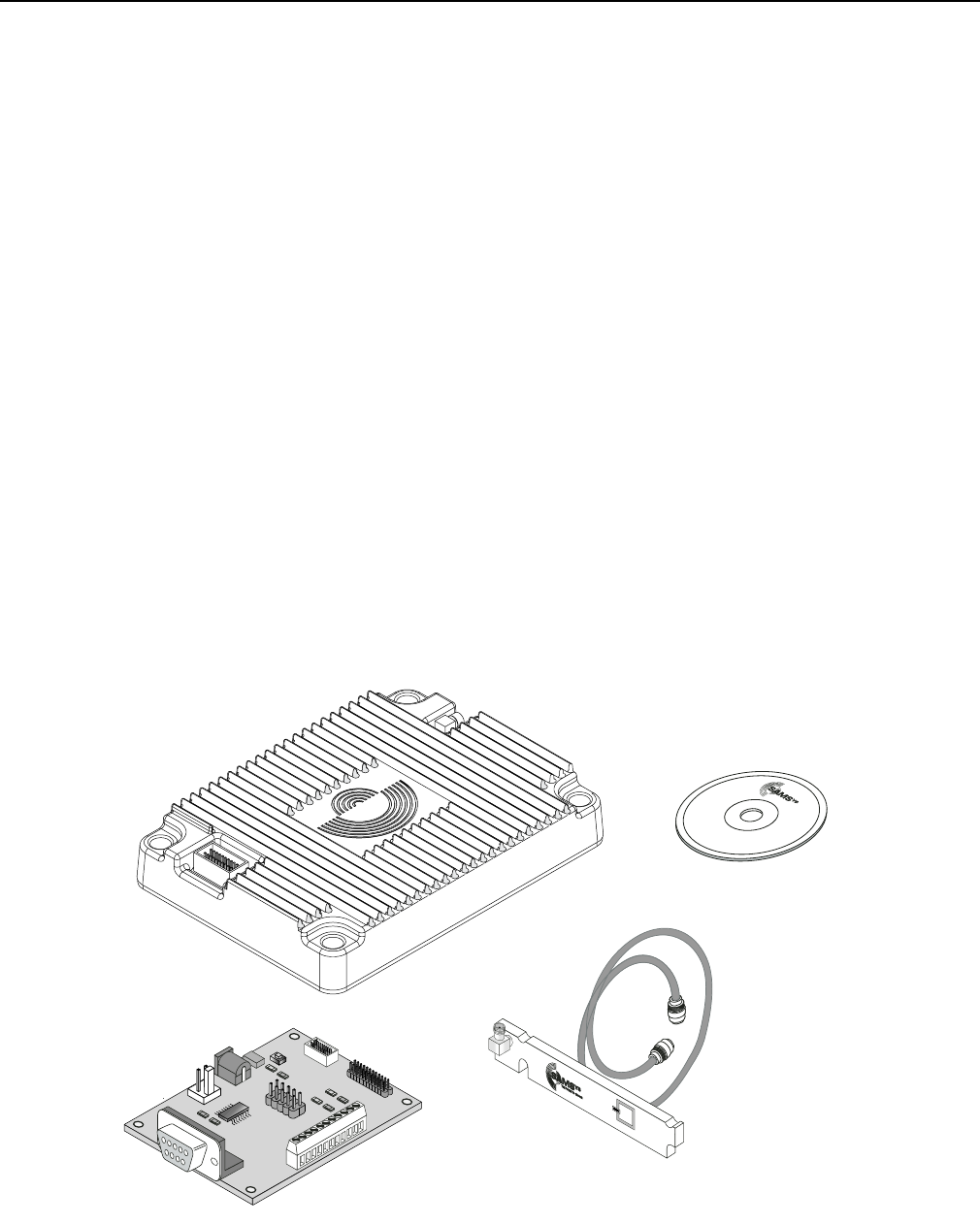
3. Verify your reader package includes the following items:
• MP9311 Low-Power UHF Reader Module
• System documentation CD
• Breakout Board (optional)
• Antenna (optional)
• Antenna cable (optional)
• Power Supply for Breakout board (optional - not shown)
• MP9311 I/O Cable for Breakout Board (optional - not shown)
Figure 1–MP9311 Reader and Accessories
T
HE
P
OWER
T
O
C
HOOSE

Introduction
3
About the MP9311
The MP9311 is an integral UHF RFID module designed for use in transponder
printer/programmers and other tag manufacturing equipment. This compact, low-
power module is capable of operating at 902 to 928 MHz for the North American
version and 865 to 869 MHz for the World Version.
The MP9311 module is capable of operating with active or passive tags while
transmitting a modulated signal. The system receiver has input bandwidths that
match the hopping channel bandwidths of the corresponding transmitters and
shifts frequencies in synchronization with the transmitted signal.
The MP9311 currently supports the following UHF protocols:
• EPC Class 1, Generation 2
• EPC Class 1
• EPC Class 0 including Impinj 0+ and Matrics 0+
• ISO 18000-6A and -6B
• IEM Marin 4022, 4222, and 4223
• Intermec Intellitag
• Philips UCODE EPC 1.19
In addition to multi-protocol architecture, the MP9311 includes an RS-232/TTL
Serial Port and digital input/output lines.
MP9311 User’s Guide
4
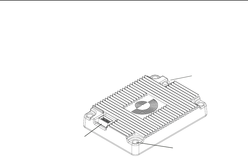
The MP9311 reader is enclosed in a shielded aluminum enclosure and contains all
digital, analog, and RF components along with power and I/O connections. The
enclosure is available with or without cooling fins depending on your operational
environment. One MMCX type antenna port and an integral power and I/O
connector is also provided.
Figure 2–MP9311 Reader Connections
Antenna Port
Power and I/O
Connector Mounting Hole
Model shown with
cooling fins.

Introduction
5
MP9311 Model Variations
The MP9311 is available in several variations depending on the region of use and
I/O configurations. The following table summarizes the different models and
configurations:
Note 1: The MP9311-Wxx models support both FCC and ETSI Frequencies. However, only ETSI is
enabled when the reader leaves the factory.
Model Region Case Interface
MP9311-NRT North America Ridges TTL
MP9311-NRR North America Ridges RS-232
MP9311-NST North America Smooth TTL
MP9311-NSR North America Smooth RS-232
MP9311-WRT World1Ridges TTL
MP9311-WRR World1Ridges RS-232
MP9311-WST World1Smooth TTL
MP9311-WSR World1Smooth RS-232

MP9311 User’s Guide
6

5
Chapter 2
Installation and Setup
This chapter provides information for installing the MP9311 Low-Power Reader
Module. Topics discussed in this chapter include the following:
• Reader Electrical Installation
– Connecting Power to the MP9311
– Connecting an RS-232 Serial Link to the MP9311
– Connecting the Digital Input and Output Lines
• Reader Mechanical Installation
• Low-Power UHF Antenna Installation
• Installing the RF Command Suite Application
• Setting Transmit Power
• Setting Antenna Gain (MP9311-Wxx only)
• Selecting the ETSI Frequency Band (MP9311-Wxx only)
MP9311 User’s Guide
6
Reader Electrical Installation
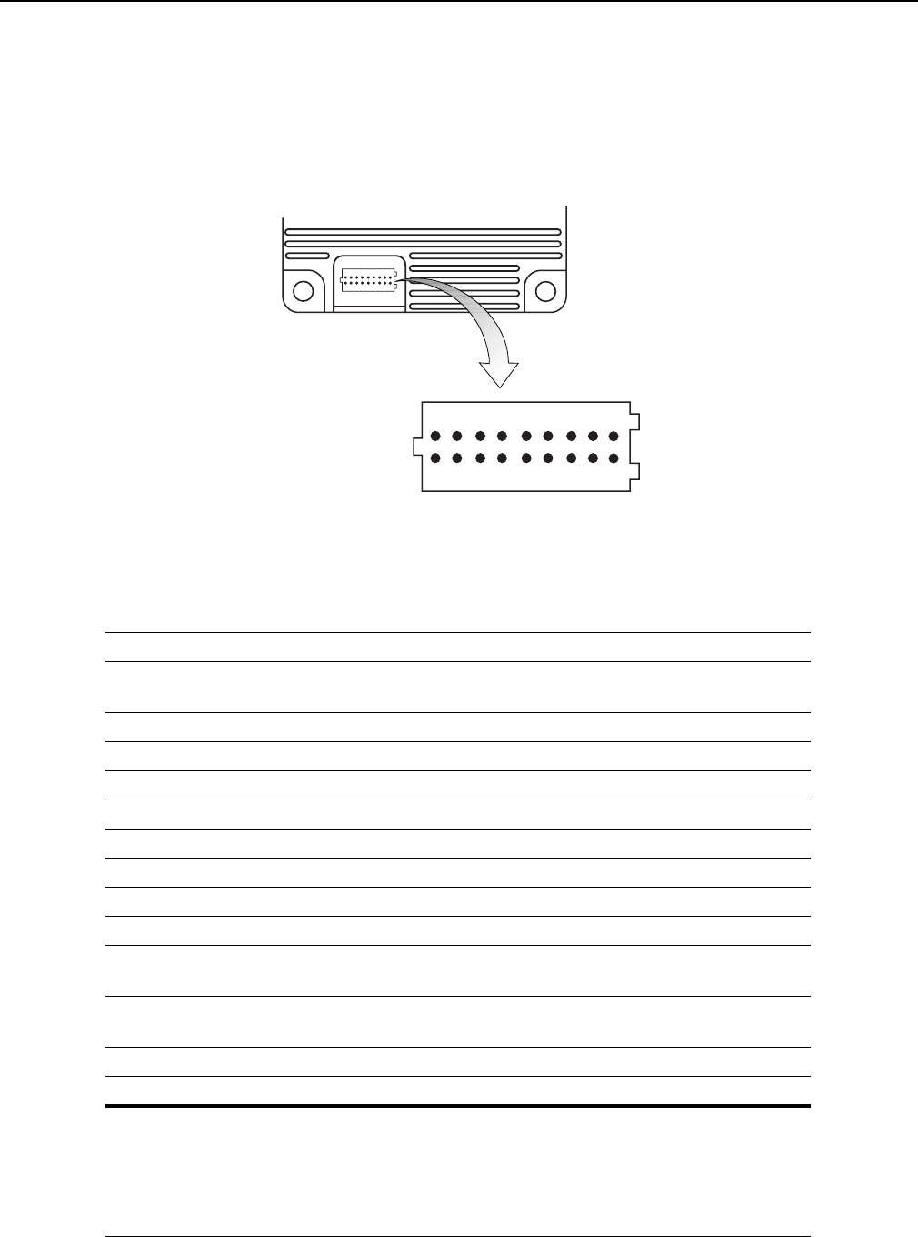
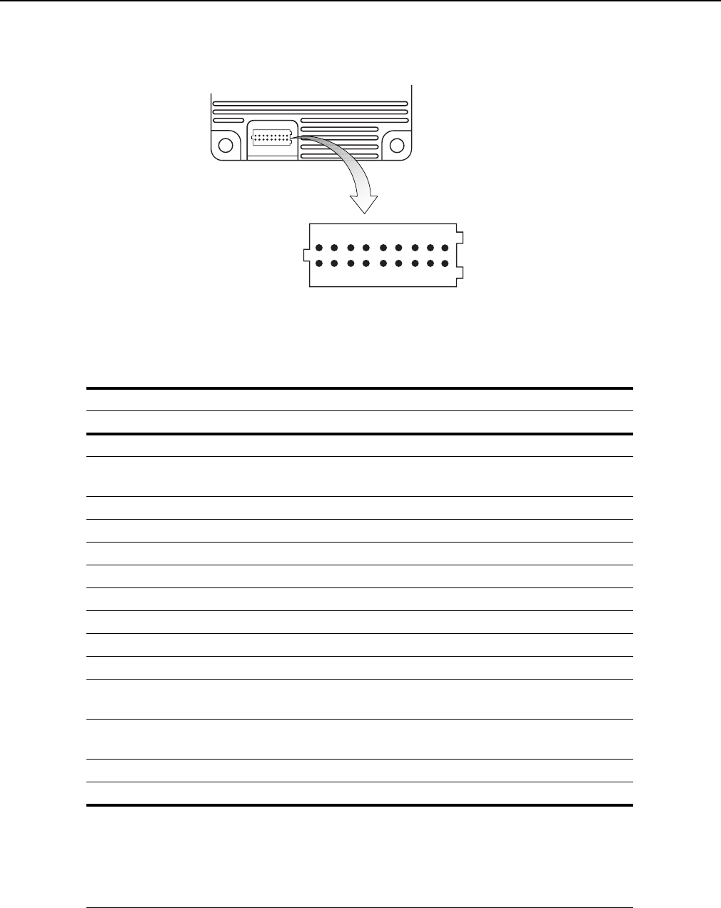
As shown in Figure 3, the MP9311 is equipped with a keyed 20-post header
(2x10), 1.0 mm pitch, .0.2 mm square pin for power, ground, and communication
connections. The antenna connection is provided by a right-angle MMCX
connector.
Figure 3–MP9311 System Connector
Pin No. Name Signal/Value
16, 18, 20 PWR System Supply Voltage, 5.0 Vdc +/-10%,
2.0A Max (All inputs tied together)
3,10,12,14,17, 19 GND Ground (All grounds tied together)
Pin 1 V33 3.3 Vdc Output (For factory use only.)
Pin 2 PROG Program Enable (For factory use only.)
Pin 4 RESET Active Low Reset
Pin 5 DIN0- Digital Input 0 – low input (see Note 1)
Pin 6 DIN1+ Digital Input 1 – high (reference) input (see Note 1)
Pin 7 DIN1- Digital Input 1 – low input (see Note 1)
Pin 8 DIN0+ Digital Input 0 – high (reference) input (see Note 1)
Pin 9 DOUT0 Digital output 0,
open collector to ground (50 Vdc @ 40 mA max)
Pin 11 DOUT1 Digital output 1,
open collector to ground (50 Vdc @ 40 mA max)
Pin 13 TXD Transmit
Pin 15 RXD Receive
NOTE 1:
To activate the digital input:
3 Vdc < (VDINn+ – VDINn-) < 25 Vdc
Otherwise:
(VDINn+ – VDINn-) ~ 0 Vdc
System Connector [SCON1]
1
2
19
20
1
2
19
20
Installation
7
Connecting Power to the MP9311
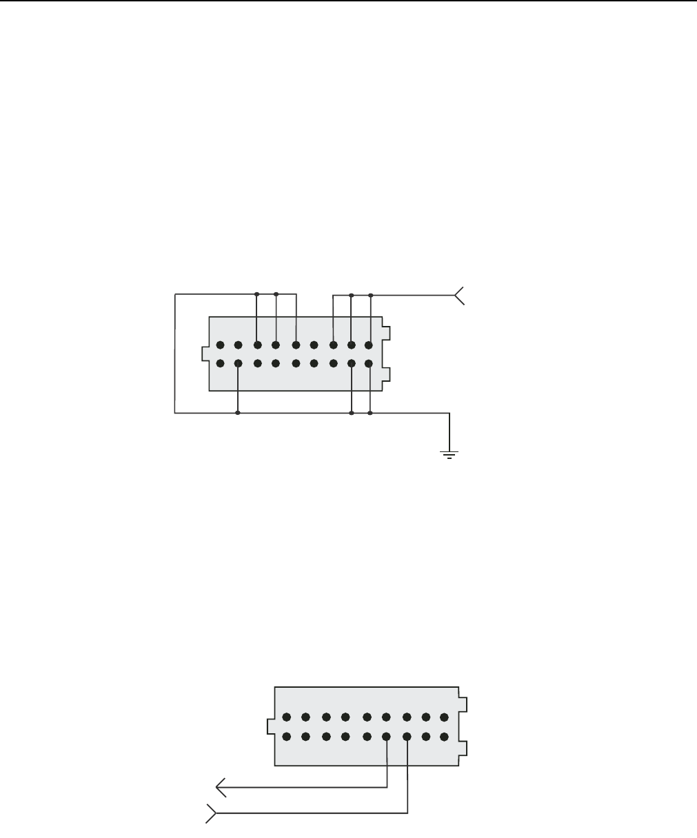
On the MP9311, all power inputs are tied together and all commons (grounds) are
tied together. To connect power to the reader, apply 5 Vdc to all SCON1 power
input pin (16,18,20) and connect ground to all SCON1 common pin
(3,10,12,14,17,19). The SCON1 connector is rated to withstand a maximum
current of 1.0A per pin. Therefore, it is important that all power and ground pins be
connected to prevent reader damage. See Figure 4.
Figure 4–System Connector (SCON1) Power Connections
Connecting an RS-232/TTL Serial Link to the MP9311
On the MP9311, RS-232/TTL signals are located on pins 13 (TXD) and 15 (RXD).
The ground signals are connected as shown in Figure 4.
Figure 5–System Connector (SCON1) Serial Connections
1
2
5 Vdc
19
20
TXD
RXD
1
2
19
20
MP9311 User’s Guide
8
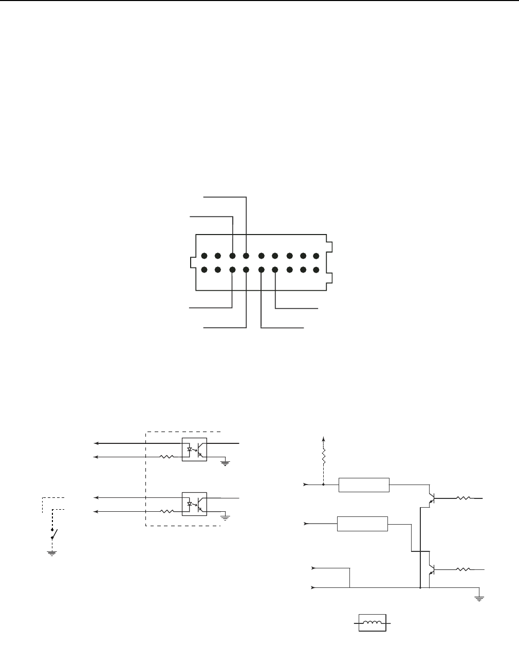
Connecting the Digital Input and Output Lines
The MP9311 is equipped with two logic-level input signals (DIN0/DIN1) and two open-
collector output signals (DOUT0/DOUT1). To activate the digital inputs apply a
minimum 3.0 Volt differential across the DINn+ and DINn-. The outputs require a 4.7K
Ohm pull-up to 5V. See Figure 7 for typical input and output circuits.
Refer to the SAMSys Forth Programming Language Reference Guide for programming
information.To set up the I/Os to trigger tag reading and indicated tag sensing, refer to the
CHUMP Reference Guide and the Protocol Configuration Word (PCW) register.
Figure 6–System Connector (SCON1) Digital Input/Output Connections
Figure 7–Typical Digital Input and Output Circuits
DIN0-
DIN1+
DIN1-
DIN0+
DOUT0
DOUT1
1
2
19
20
4.7K
Digital Inputs
DIN0+
DIN0-
4.7K
Typical input
drive circuit
(user supplied)
Vref
DIN1+
DIN1-
Digital Outputs
DOUT0 Filter
4.7K
+5 Vdc Typical output
pull-up circuit
(user supplied)
DOUT1
Ground
60 V, 500 mA max
Non-inductive Typical Filter
Filter
(SCON1-8)
(SCON1-5)
(SCON1-6)
(SCON1-7)
(SCON1-9)
(SCON1-11)
(SCON1-12)
(SCON1-10)
Installation
9
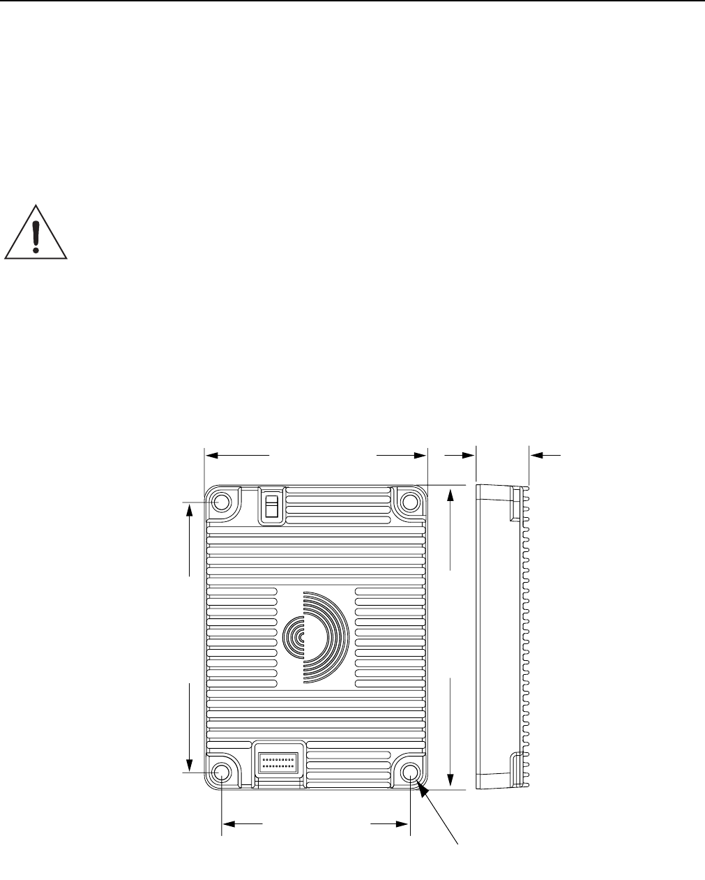
Reader Mechanical Installation
The MP9311 is designed for installation within an enclosure. The housing is
provided with four M4 clearance through-holes for module mounting. The reader
dimensions are shown in Figure 8.
Caution Prior to mounting the reader in an enclosure, you must evaluate the operating conditions
and resulting thermal profile. When operated at maximum RF power and input supply
voltage, the MP9311 can dissipate as much as 11W of power. As a result, any enclosure
design must dissipate the generated thermal energy and maintain the internal reader
temperature below +85 degrees C. Mounting the bottom surface of the reader in direct
contact with a metal plate will provide the most efficient method of dissipating heat.
Figure 8–MP9311 Enclosure Dimensions
3.32 in (84.3 mm)
3.74 in (95.0 mm)
0.57 in (14.5 mm)
(without cooling fins)
or
0.67 in (17.0 mm)
(with cooling fins)
2.74 in (69.6 mm)
2.32 in (58.9 mm)
M4 Clearance
R0.20 Max Screw Head Size
MP9311 User’s Guide
10
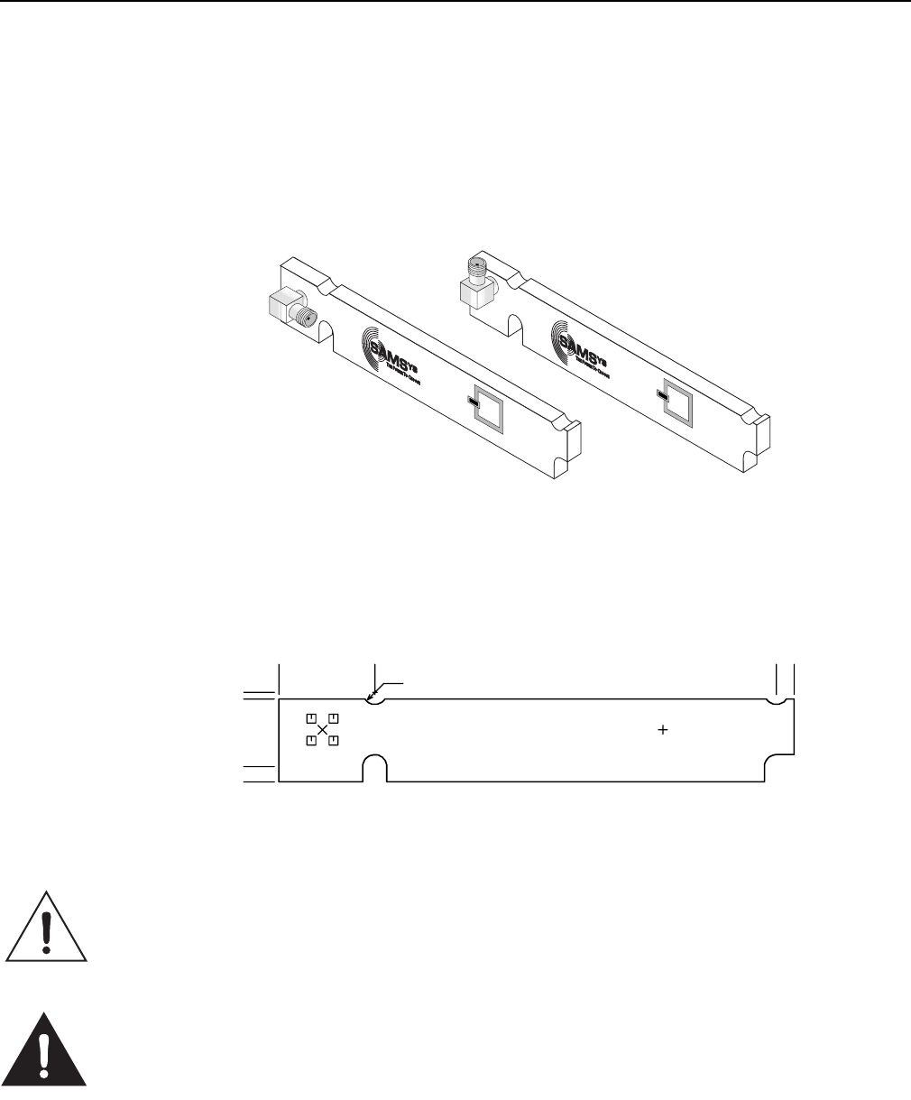
Low-Power UHF Antenna Installation
The MP9311 is designed to operate with the SAMSys Label Printer Antenna. This
antenna has an expected read range of 1-12 inches and only requires a power
output of approximately 17 dBm for optimal performance.
Figure 9–Low-Power UHF Antennas
As shown in Figure 10, mounting slots/cutouts are provided. Do not attempt to drill new
mounting holes in the antenna.
Figure 10–Label Programmer Antenna Dimensions
Caution To prevent reader damage, the RF port must be properly terminated with a 50 Ohm load
or a functional UHF RFID antenna before power up. Never power up the reader unless the
loads or antennas are connected. Always power down the reader before removing an
antenna or load from an RF port.
FCC Radiation Exposure Statement
The antennas used for this transmitter must be installed to provide a separation distance
of at least 20 cm from all persons and must not be co-located or operating in conjunction
with any other antenna or transmitter.
0.808
0.748
0.138
0
0.8670
0.108 RAD.TYP.
4.488 4.646
0.187" THK. MAT'L

Installation
11
Installing the RF Command Suite Application
The SAMSys RF Command Suite is a Microsoft Windows application that
provides a Graphical User Interface (GUI) for SAMSys RFID Reader Products.
The application allows you to easily view tag data, configure the reader, and perform other
tag data functions. In addition, the RF Command Suite is the preferred method for sending
CHUMP commands to a reader. The RF Command Suite application is provided on the
CD shipped with your reader and can be installed on a personal computer. To install RF
Command Suite, refer to Chapter 1 - Introduction in the RF Command Suite User’s Guide.

MP9311 User’s Guide
12
Setting Transmit Power - TD0
Output power on the MP9311 is set by configuring the Transmit Power (TD0) register.
The output power is entered in tenths (1/10) of dBm with steps of 1/10 dBm. All
values are in decimal. For example, entering a value of 121 equates to 12.1 dBm.
For example, to set the MP9311 output power to 17.5 dBm, issue the following
CHUMP command to the reader:
}Cw,d:TD0,b:175!
The valid range of values for TD0 is from 0 (0 dBm) to 280 (28 dBm).
Setting Antenna Gain - TG0 (MP9311-Wxx only)
In order to comply with ERP and threshold limits according to EN 302 208,
MP9311-Wxx models must be configured with the proper antenna gain. Antenna gain
is set by the TG0 register. Before operation, you must determine the actual antenna
gain used in the installation, GA.
To program the TG0 register, issue the following CHUMP command to the reader:
}Cw,d:TG0,b:xxx,f:1!
Where:
xxx is computed as follows: xxx = (GA (db) + 13.0) * 10
The range of allowable xxx is 000 through 230 which gives an allowable antenna gain
range of -13dB to +10dB. Proper LBT operation according to EN 302 208 is not
guaranteed with antennas outside of this range.

Installation
13
Selecting ETSI Frequency Bands (MP9311-Wxx only)
Single Frequency Selection
MP9311-Wxx readers can be configured to operate in one of the following ETSI
single frequency bands (as defined in ERC/REC 70-03 and EN302-220).
• Annex 1 Band I - 869.525 MHz
• Annex 1 Band k - 869.850 MHz.
These bands are selected by setting Bits 28 and 29 of the 32-bit Transmit Power
Configuration (TPC) register. For additional information on TPC register bit
settings, refer to Figure 11.
To select Band I - 869.525 MHz, issue the following command to the reader:
}Cw,d:TPC,b:00000000!,f:1!
To select Band k - 869.850 MHz, issue the following command to the reader:
}Cw,d:TPC,b:10000000!.f:1!
Frequency Hopping Selection
In addition, MP9311-Wxx model readers can be configured to operate in the ETSI
frequency hopping band (as defined in EN 302-208).
To select EN 302-208 operation, issue the following command to the reader:
}Cw,d:TPC,b:00040000!,f:1!
MP9311 User’s Guide
14
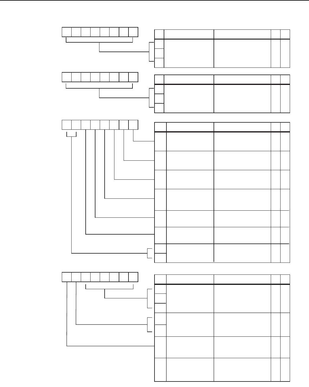
Figure 11–TPC Bit Configuration
Reserved
1617181920212223
D16
Bit Name Setting/Function
D17
D18
D19
Tx DAC Pwr
D0
Bit Name Function
D7
01234567
Tx DAC power setting
for the current antenna.
Bits 0-7.
89101112131415
D8
Bit Name Function
D15
Tx DAC Pwr Tx DAC power setting
for the current antenna.
Bits 8-15.
Frequency control 0 = ETSI
1 = FCC
Disable Tx drift
compensation
Enable ETSI
frequency hopping
Suppress Antenna
check (see following
Caution statement)
D20
D21
Reserved
2425262728293031
Bit Name Setting/Function
D24
D27
D31
Suppress RXD check
Warning message
(see Caution stmnt)
RW
RW
X
X
RW
RW
0 = Enable Tx drift comp.
1 = Disable
0 = Disable
1 = Enable ETSI freq hop
0 = Do not suppress
1 = Suppress ant check
0 = Do not suppress
1 = Suppress RXD check
XX
XX
XX
XX
XX
Reserved
Reserved
D22
D23
Hop Sequence 0 = Random
1 = Sequential
D30
Suppress RXD Check
fault LED and msg 0 = Do not suppress
1 = Suppress XX
D28
D29
ETSI Frequency
Select
00 = Band I - 869.525 MHz
01 = Band k - 869.850 MHz XX
XX
Reserved Reserved

15
Chapter 3
Operation
This chapter provides general information to operate the MP9311 Low-Power
UHF Reader Module. Topics discussed in this chapter include the following:
• MP9311 Power Up and Initialization
• Setting the RF Mode
• Selecting Tag Protocols
• Enabling Tag Protocols
• Configuring Specific Protocols
• Reading Tags
• Writing Blank Tags
• Modifying Tags
• Resetting the MP9311

MP9311 User’s Guide
16
MP9311 Power Up and Initialization
When the power supply is connected, the MP9311 starts an internal initialization
sequence.
After the initialization sequence, the reader activates the RF field and, depending
on the configuration, begins transmitting read detect (Rd) commands at the
specified frequency.
Setting the RF Mode
The MP9311 is factory configured for continuous RF scanning or “auto-read” mode. This
mode is equivalent to mode selected by the Auto Read function key on the RF Command
Suite Command interface window.
If desired, you can reconfigure the reader for Polled RF mode (reader activates the
transmit carrier and waits for host to send a read command). Select the Polled Read
function key to activate Polled RF mode.
To halt the Auto Read or Polled Read mode, press the RF Off function key.
Selecting Tag Protocols
The MP9311 is factory configured with only those protocols selected by the user. Once
protocols are activated, the Command tab function keys can be used to select the protocol.
These function keys are programmed with specific command sequences required by the
reader to select a particular protocol. To select a specific protocol, perform the following:
1. Select the Command interface window.
2. Select Function Set 2 or 3 and locate the required protocol.
3. Press the function key to select the protocol.
4. To view the command sequence performed by this function, hold the mouse pointer
over the key or right click while holding the mouse pointer over the key and select
Edit Macro.
5. Do not change the command sequnce unless you are experienced using SAMSys
CHUMP commands to configure readers.
Operation
17
Enabling Tag Protocols
SAMSys readers can be configured with different tag protocols. If your reader was
loaded with specific protocols at the time of purchase, these protocols can be
enabled or disabled as required. To verify which protocols are enabled for your
reader, select:
Reader Configuration
D
General Configuration
D
Operating Mode
D
Protocol Select Word
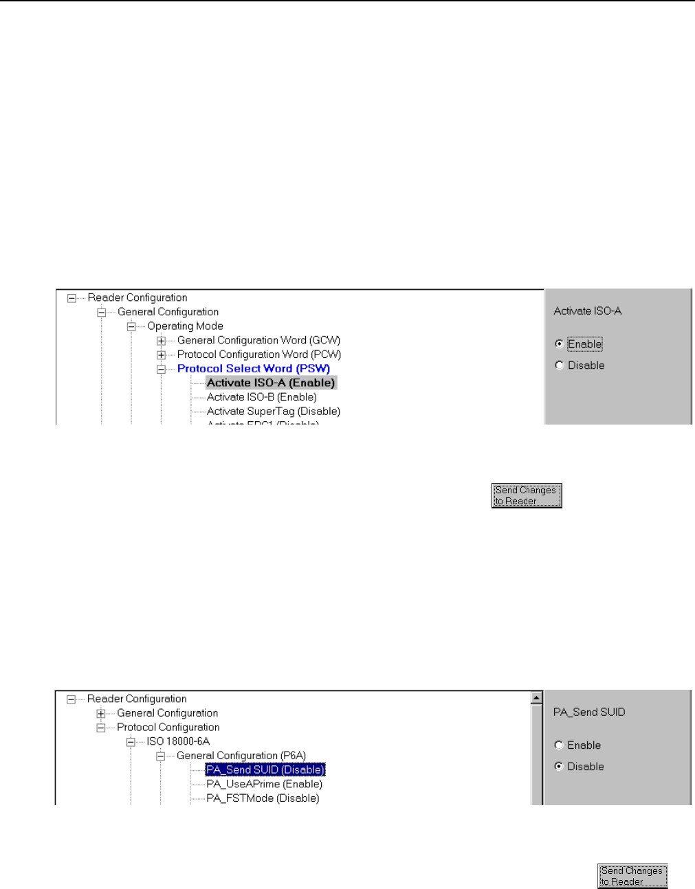
To configure the reader for a specific protocol, perform the following:
1. Select the Protocol Select Word (PSW) parameters as shown in the following:
Figure 12 – Protocol Selection
2. Enable or disable a protocol by using the selectors on the right side of the
display and press Send Changes to Reader .
Configuring Specific Protocols
Individual Protocol Configuration registers can be modified for specific tag types
and read modes. For specific protocol configuration register information, refer to
the Comprehensive Heuristic Uniform Messaging Protocol (CHUMP) Reference
Guide. To configure individual protocol registers, perform the following:
1. Select the individual protocol configuration word parameters.
Figure 13 – Protocol Parameter Configuration
2. Enable or disable a specific protocol parameter by using the selectors on the
right side of the display and press Send Changes to Reader .
MP9311 User’s Guide
18
Reading Tags
Tag Reading Overview
When the reader completes the initialization sequence, the reader activates the RF field
and, depending on the configuration, begins transmitting read detect (Rd) commands at
the specified frequency. When a tag is placed within range, the reader activates the tag and
reads the data. The following example shows a typical Rd return message with tag data
that was returned by the reader:
{Rd,d:E016000000000D53,t:IS186A;C4
Reading Tags Using RF Command Suite
RF Command Suite is automatically configured to display tag data as the data is
received from the reader. However, tool settings can be changed to match your
requirements. Refer to the following sections and the RF Command Suite User’s
Guide to configure the application.
To configure the RF Command Suite for your reader, perform the following:
1. From the tool bar pull-down menu, select File
D
Load Macro File.
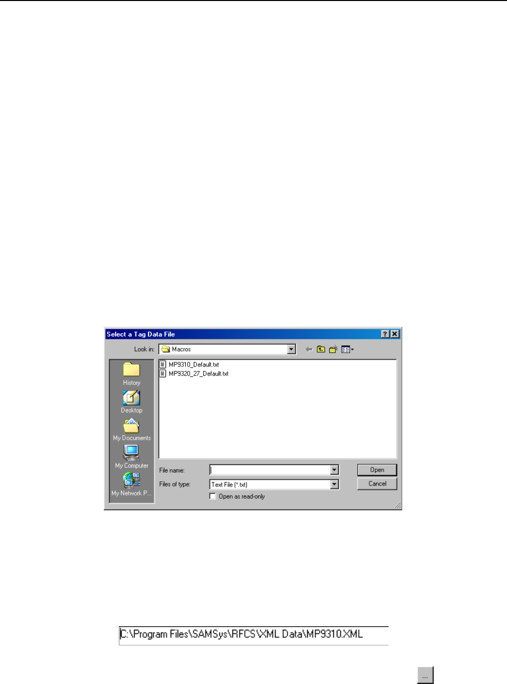
2. Navigate to C:\Program Files\SAMSys\RFCS\Macros and select the
MP9310_Default.txt file and press Open. This will reconfigure the function keys and
other aspects of the RF Command Suite to match the MP9311.
3. In addition to the macro file, load the correct XML configuration file. Select the
Reader Config Interface and verify the correct XML configuration file is shown in
the Path to XML Configuration Definition.
4. If the path does not show the MP9310.xml file, press the Browse button and
choose MP9310.xml.
Operation
19
5. After selecting the correct XML configuration file, press Open. The file path is
automatically saved.
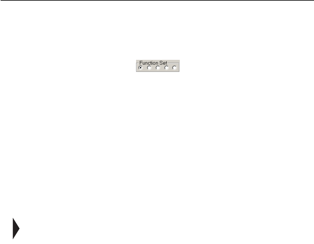
6. Configure the reader for Auto Read. Select the Command interface and then select
Function Set 1.
7. Press Auto Read.
8. Verify the reader is configured for the correct protocol. Select the Command
interface and then select the radio button for Function Set 2 or 3.
9. After locating the protocol on the function key, press the key to activate the protocol.
10. The MP9311 is now ready to begin reading tags.
External Triggered Tag Inventory Operation
In many applications, the MP9311 can be triggered by an external device such as a
proximity switch or optical sensor. In these cases, the MP9311 can be configured
to generate tag inventory operations (Rd) for as long as Digital Input 0 (DIN0) is
asserted. Digital Output 0 (DOUT0) can also be set to indicate that a successful tag
inventory operation was performed.
NOTE: The tag inventory operation performs a process called singulation on the tag population
and obtains the tag ID for those tags in the RF field.
Reader Setup
To setup the reader for external trigger, several MP9311 configuration registers
must be modified. Perform the following to setup the reader for external trigger:
1. Verify you have RF Command Suite installed on your PC.
2. Start up RF Command Suite and select the Command interface tab.
3. Press the Auto Read function key (Function Set 1).
4. Place a tag in the RF field and verify the tag data is displayed on the Tag Summary
interface.
5. Next, set the Protocol Configuration Word (PCW) to enable triggered reads on Digital
Input 0 and output a read verification on Digital Output 0 (this is equivalent to setting
the PCW to 0x2200).
6. On the Reader Config interface tab, select:
Reader Configuration
D
General Configuration
D
Operating Mode
D
Protocol Configuration Word (PCW)
D
Digital ...
7. Set Digital output 0 (DOUT0) pulse on tag activity to Enable.
MP9311 User’s Guide
20
8. Set Digital input 0 (DIN0) gates auto read action to Enable.
9. Finally, set the duration of the output pulse. On the Reader Config interface tab,
select:
Reader Configuration
D
General Configuration
D
Operating Mode
D
Protocol Digital I/O Control
10. Enter a value in milliseconds.
11. Press Send Changes to Reader to reconfigure the reader with the news settings.
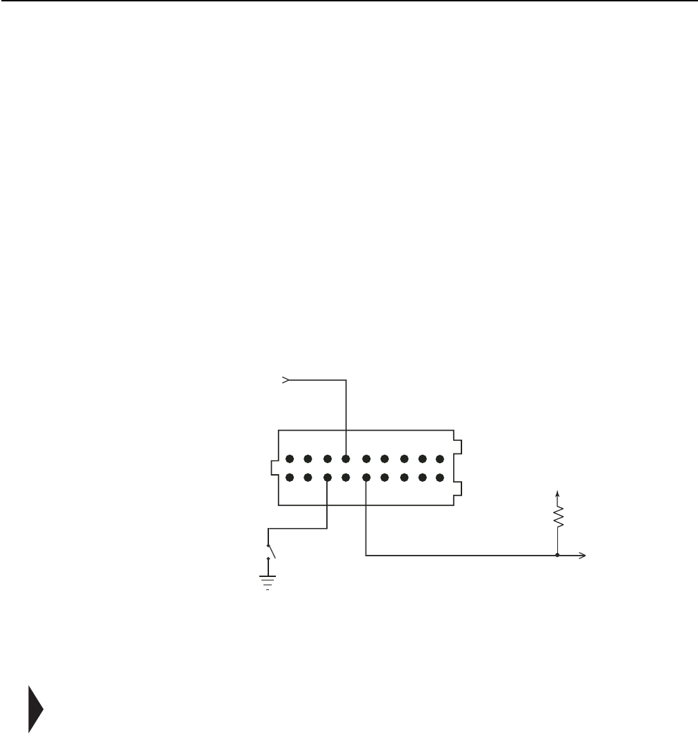
Connecting the External Trigger Circuit
12. As shown in Figure 14, apply +5 Vdc to DIN0+ (Pin 8) on SCON1.
13. To trigger a read, pull DIN0- (pin 5) Low (0 Vdc or ground) for at least 50
milliseconds.
Figure 14–Typical Digital Input Trigger Circuit
14. When a tag is singulated, DOUT0 goes high for the duration set by the PIO register.
NOTE: When a tag is read, DOUT0 is asserted and stays asserted as long as tag activity
continues. The pulse duration calculation is reset with each valid read. Therefore, if the
pulse is still in process and a read operation is performed, the pulse will be extended by
the value contained in PIO. This logic guarantees a pulse of a specific duration since the
last read that occurred
+5 Vdc
External Trigger
(hold for 50 mSec)
4.7K
+5 Vdc
DIN0-
DIN0+
DOUT0
1
2
19
20
Operation
21
Writing Blank Tags
RF Command Suite can be used to write unprogrammed or blank tags. To write
blank tags, perform the following:
1. Select the Command interface and verify the reader is connected and the
correct protocol is selected.
2. Place the reader in Polled Read mode.
3. Verify a single tag is in the RF field of the reader.
4. Select the Tag Summary interface.
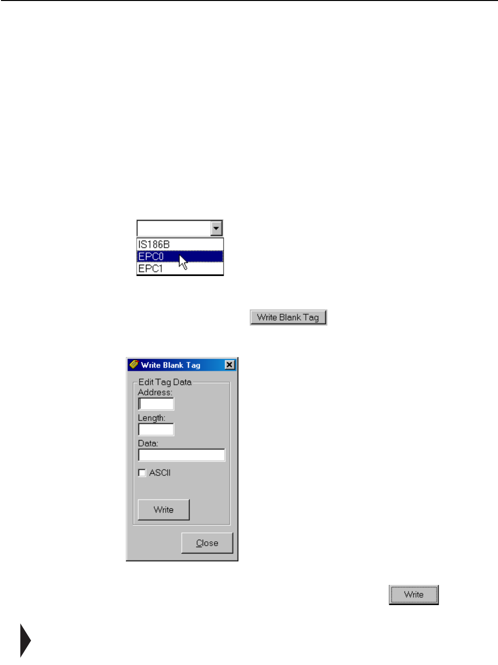
5. Select the protocol from the pull-down above the Write Blank Tag button.
Figure 15–Select Tag Protocol
6. Press the Write Blank Tag button to begin the operation and
display the tag data box.
Figure 16–Write Blank Tag
7. Fill in the appropriate data (in Hex) and press the Write button to
write the data to the tag.
NOTE: For detailed information on the various tag protocols and how each protocol is
programmed, refer to Appendix A –Tag Programming.
MP9311 User’s Guide
22
Modifying Tags
RF Command Suite can be used to modify previously programmed tag data. To
modify tags, perform the following:
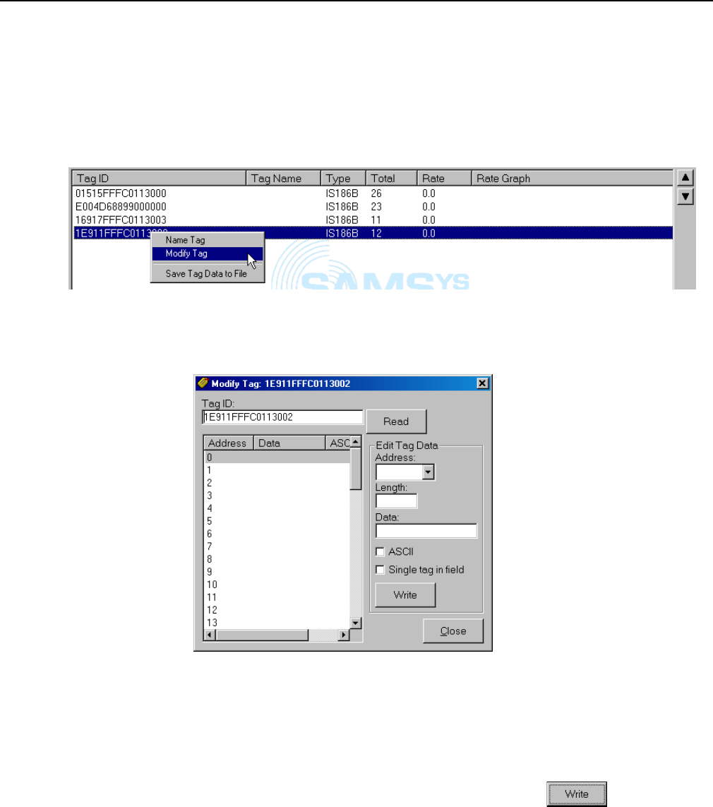
1. Select the Tag Summary interface and right-click on the tag.
Figure 17–Select Tag to Modify
2. Select Modify Tag. The tag data window is displayed.
Figure 18–Modify Tag Option
3. Select the Address from the pull-down.
4. Enter the data Length and actual Data for the specific address
5. Select if ASCII data and whether or not there is a Single tag in field.
6. After all data and parameters are entered, press Write .
7. Repeat for each address.
Resetting the MP9311
To reset the MP9311, drive the reset line low for 3 ms. Refer to Chapter 5 -
Specifications for detailed information for location of the reset pins on the system
connector (SCON1).

23
Chapter 4
Troubleshooting
This chapter provides general information to troubleshoot the MP9311 Low-Power UHF
Reader Module. Topics discussed in this chapter include the following:
• General Troubleshooting
•Contact Us
MP9311 User’s Guide
24
General Troubleshooting
SAMSys readers are designed, manufactured, and tested to provide many years of trouble-
free service. However, in the event of a reader malfunction or failure, refer to the
following troubleshooting instructions to help identify and correct the problem.
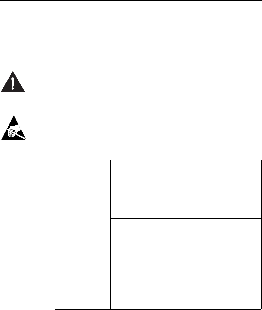
Warning - Electric Shock Hazard
The following procedures may involve AC voltage. Use extreme caution when measuring
voltage or installing cables and power supplies. Serious injury or death may occur if
proper precautions are not observed.
Caution - ESD
The following procedures involve electrostatic discharge sensitive components. ESD
protection is required. Damage to the reader can occur if proper ESD equipment such as
grounded wrist straps and ESD protected work surfaces are not used.
Symptom Probable Cause Corrective Action
Reader appears to
lock up. Readers are vulnerable
to high ESD pulses. As
a result, the reader can
lock up.
Disconnect the power from the reader
and reconnect. The reader should
reset. If the reader does not function
normally after reset, replace the reader.
No RS-232
Communication. External RS-232 cable
malfunction Check cable connectors for bent or
broken pins. Replace external RS-232
cable if necessary.
Reader board failure. Replace reader.
No Digital I/O signals
present. Reader board failure. Replace reader.
Incorrect wiring Recheck digital I/O circuit as shown in
Chapter 2 - Installation.
Tag ID/data is different
from expected value. Reader software
version. Program reader with latest software
version release.
Electromagnetic
interference. Shield or reposition reader
Tag read failure. Read range exceeded. Reposition reader or tag.
Tag speed exceeded. Slow tag when within range of reader.
Faulty tag. Verify reader operation with a known
good tag.
Troubleshooting
25
Contact Us
For any questions regarding products and services, including returns, repairs, technical
support, training, and all other available services, contact your distributor or SAMSys
Customer Service at the following:
E-mail support@samsys.com
Telephone 1-877-367-4342 (toll free)
8:00am-6:00pm EST, Mon-Fri
Fax 1-919-281-1551

MP9311 User’s Guide
26

27
Chapter 5
Specifications
This chapter describes the specifications for the MP9311 Low-Power Reader Module.
Information provided includes the following:
• Reader Specifications
• Antenna Specifications
• Environmental Specifications
• Power and Input/Output Connector

MP9311 User’s Guide
28
Reader Specifications
Parameter Value
Frequency
(North American) 865 to 928 MHz
Transmit Power 0.002 to 0.6 Watt (conducted)
Transmit Power Step Size 0.1 dBm
Carrier Frequency Stability +/- 10 ppm
Receive Sensitivity -96 dBm
Connections Serial (RS-232 or TTL), Digital I/O
Supply Voltage 5.0 Vdc +/-10%
Current 0.8 – 2.0 Amp maximum
Enclosure Material Aluminum
Case Dimensions,
MP9311-xRx (with cooling fins) 2.74 x 3.74 x 0.67 in
(69.6 x 95.0 x 17.0 mm)
Case Dimensions,
MP9311-xSx (without cooling fins) 2.74 x 3.74 x 0.57 in
(69.6 x 95.0 x 14.5 mm)
Mounting holes M4 Clearance Through Holes
2.32 x 3.32 in spacing
(58.9 x 84.3 mm)
Weight (approx) 4.5 oz (127.6 g)
Specifications
29
Antenna Requirements
The antennas used with this transmitter must be professionally installed in a
manner which guarantees compliance with all local laws and regulations.
Note 1: To comply with EN 302 208, the installer must use an antenna whose beamwidth shall be
less than or equal to 90 degrees for transmit ERP levels less than or equal to 500 mW. For
transmissions above 500mW and less than or equal to 2W, a minimum antenna beamwidth
of 70 degrees is required.
Note 2: In accordance with local regulation.
FCC Radiation Exposure Statement
The antennas used for this transmitter must be installed to provide a separation distance
of at least 20 cm from all persons and must not be co-located or operating in conjunction
with any other antenna or transmitter.
Caution
To prevent reader damage, the RF port must be properly terminated with a 50 Ohm load
or a functional UHF RFID antenna before power up. Never power up the reader unless the
loads or antennas are connected. Always power down the reader before removing an
antenna or load from an RF port.
Environmental Specifications
Caution
The actual internal module temperature is a function of the operating conditions and end
product enclosure environment. The maximum recommended module internal operating
temperature is +85°C and can be monitored with host software. The embedded RFID
application should be verified and monitored for compliance.
Antenna Parameter North American (FCC) European Union (ETSI)
302-208 300-220
Frequency 902 to 928 MHz 865 to 868 MHz 869.525 MHz
Polarization Circular or Linear Circular or Linear Circular or Linear
Impedance 50 Ohms 50 Ohms 50 Ohms
SWR, maximum 1.75:1 1.75:1 1.75:1
Antenna gain 9 dBi, Max See Note 1 See Note 2
Specification Value
Operating
Temperature -4° F to 131° F (-20° C to 55° C)
See the following Caution statement
Storage Temperature -40° F to 176° F (-40° C to 80° C)
Relative Humidity 5% to 80% non-condensing
MP9311 User’s Guide
30
Power and Input/Output Connector
System Connector (SCON1) Specifications
Connector Type Specification
20-Pin Dual Row 2 x 10 Header, (2x10), 1.0 mm pitch, .0.2 mm square pin
Pin No. Name Signal/Value
16, 18, 20 PWR System Supply Voltage, 5.0 Vdc +/-10%,
2.3A Max (All inputs tied together)
3,10,12,14,17,19 GND Ground (All grounds tied together)
Pin 1 V33 3.3 Vdc Output (For factory use only.)
Pin 2 PROG Program Enable (For factory use only.)
Pin 4 RESET Active Low Reset
Pin 5 DIN0- Digital Input 0 – low input (see Note 1)
Pin 6 DIN1+ Digital Input 1 – high (reference) input (see Note 1)
Pin 7 DIN1- Digital Input 1 – low input (see Note 1)
Pin 8 DIN0+ Digital Input 0 – high (reference) input (see Note 1)
Pin 9 DOUT0 Digital output 0,
open collector to ground (50 Vdc @ 40 mA max)
Pin 11 DOUT1 Digital output 1,
open collector to ground (50 Vdc @ 40 mA max)
Pin 13 TXD Transmit
Pin 15 RXD Receive
NOTE 1:
To activate the digital input:
3 Vdc < (VDINn+ – VDINn-) < 25 Vdc
Otherwise:
(VDINn+ – VDINn-) ~ 0 Vdc
System Connector [SCON1]
1
2
19
20
1
2
19
20

31
Appendix A
Tag Programming
This appendix describes how to program tags of varying protocols using CHUMP
commands sent from a terminal or console.
Information provided in this appendix includes the following:
• Overview of the Tag Writing Command
• Programming the EPC1 Tag
• Programming the ISO 18000-6A Tag
• Programming the ISO 18000-6B Tag
• Programming the Impinj EPC0 Tag
• Programming the Matrics Class 0+ Tag
• Programming the EPC1, Generation 2 Tag

MP9311 User’s Guide
32
Overview of the Tag Writing Commands
Tag writing with SAMSys readers is performed using the Write Any (Wa), Write Tag (Wt),
and Write Verify (Wv) commands Wa must be used when writing to blank tags. Wt is used
when the tag already has a tag ID. Wv is a multifunction command that performs any erase,
write, and verification needed to program a tag in a specific protocol. This command can
also lock the data. A general guideline for using each write command is as follows:
Wa is used whenever the write operation affects the tag ID. Wa can also be used for write
operations to any data on a tag. This command is executed with a single tag in the RF
field.
Wt can only be used for write operations to a specific tag where the tag ID has already
been assigned. This command can be used for write operations to any data on the tag,
except the tag ID itself.
Wv can be used for most protocols. However, it is typically used for EPC protocols that
require multiple actions such as erasing the tag prior to writing and then locking the data.
Some tags support the ability to have a portion or all of their internal memory locked
against further modification. Write operations to locked memory will not be successful.
The locked status of a piece of memory can be queried via the Yl command. The Yl
response is f:0 for unlocked or f:1 for locked.
Details of the syntax for any command found in this document can be obtained in the
CHUMP Reference Guide.

Tag Programming
33
Programming the EPC1 Tag
SAMSys UHF readers can be used to program 64-bit and 96-bit EPC1 tags.
Both the Wa and Wv command can be used with the EPC1 (Alien) tags. The Wv command
is discussed at the end of this section.
Do not use Wt since the tag does not support singulated write operations.
Prior to writing, EPC1 tags must be erased. The Wv command and the Wa with the f:3
option will perform the erase action during command execution. If the command specified
does not erase the tag during the command execution, then specify the erase operation
separately using the Tag Erase (Te) command.
Also, in order to calculate the CRC, the entire tag ID must be presented to the reader in
one command. EPC1 tags contain an internal CRC value which covers the EPC ID and the
kill passcode. The reader always calculates the CRC and writes the correct value to the
tag during the write operation. As a result, the entire tag ID and passcode must be
presented to the reader in one command. The last byte of the blk data passed in the Wa
command is the kill passcode. In the examples that follow, this passcode is set to 00.
The format of the Wa command is as follows:
}Wa,a:<blk addr>,b:<blk data>[,l:<# blks>]
[,f:<control flag>]!
where:
a:<blk addr>. This parameter is optional since there is only a single writeable
piece of memory. If specified, the parameter should use block address 0x00.
l:<# blks>. This parameter reflects the number of bytes being written and should
be equal to 9 if writing a 64-bit EPC ID with the kill passcode or equal to d if writing
a 96-bit EPC ID with the kill passcode. If you are not specifying the kill code, the
values should be 8 and C, respectively.
b:<blk data>. This parameter must contain the entire EPC ID (64- or 96-bit),
followed by the one byte kill passcode.
f:<control flag>. This parameter controls operations related to writing a tag.
Set f:1 to verify the data in the tag following the write operation. Set f:2 to erase
the data prior to the write operation. For most applications, set both of these bits with
f:3.
The following is a typical command to write a 96-bit EPC1 ID tag:
}wa,a:0,b:80020304050607090a0b0c0e00,l:d,f:3!
The following is a typical command to write a 64-bit EPC1 ID tag:
}wa,a:0,b:800080042504600200,l:9,f:3!

MP9311 User’s Guide
34
In addition to the Wa, Te, and Tr commands, SAMSys readers also support the following
EPC1 operations:
•Lb Lock Block
•Yl Query Lock Status (returns f:0 for unlocked or f:1 for locked)
•Td Tag Destroy
The Lock Block and Query Lock Status operations can only be performed with a single
tag in the RF field and do not require any parameters. The Tag Destroy operation requires
the b: parameter to specify the particular kill passcode for this tag.
For detailed information on these and other tag commands, refer to the Comprehensive
Heuristic Unified Messaging Protocol (CHUMP) Reference Guide.
Using the Wv Command
The Wv command is a multifunction command that performs any erase, write, and
verification needed to program a tag in a specific protocol. The command can also lock the
data.
The format of the Wv command is as follows:
}Wv,b:<EPC data>,m:<lock mask>,k:<kill code>
where:
b:<EPC data> is the EPC ID to write to the tag.
k:<kill code> is the kill code to be written to the reader.
m:<lock mask> is the lock mask to indicate which tag field to lock. Each 4-bit
nibble in the mask indicates the lock state to apply to a specific part of the tag. A mask
nibble value of 1 locks the specific part of the tag. A mask nibble value of 0 indicates
no lock is applied.
For the EPC1 protocol, the mask nibbles apply to the following fields:
To write an EPC ID value of 332233445566778899aabbcc and verify the write, enter:
}wv,b:332233445566778899aabbcc!
To write the EPC ID data and lock the data, enter:
}wv,b:332233445566778899aabbcc,m:1!
Mask Nibble 43210
Tag Field Unused Unused Unused Kill code EPC data

Tag Programming
35
Programming the ISO18000-6A Tag
Both the Wa and Wt command can be used with the ISO18000-6A tag. In addition to Wa
and Wt, two additional commands can modify specific data in the tag. The Wd command
modifies the DSFID and Wf modifies the AFI.
Typically, the Wt command is used to modify user data in the tag. The Wt, Wd, and Wf
commands require the tag ID to be in the d: parameter. Also, the tag must first be put in
the SELECT state using the Ts command with the tag ID specified in the d: parameter.
NOTE: Some varieties of ISO18000-6A tags are not writeable. Check with your tag vendor
to verify if your tag supports write operations.
The format of the Wa command is as follows:
}Wa,a:<blk addr>,b:<blk data>[,l:<# blks>]!
where:
a:<blk addr>. In ISO18000-6A, only a single block can be written at one time
and this parameter represents the specific four byte block.
l:<# blks>. This parameter is optional since each write operation must contain
exactly four bytes.
b:<blk data>. This parameter must contain four bytes of data.
The following is a typical command to write to an ISO18000-6A tag:
}wa,a:0,b:01020304!
For example, to write AABBCCDD to address 0x20 on a tag with ID
E00300001122334455667788, issue the following command:
}wt,d:E00300001122334455667788,a:20,b:AABBCCDD!
In addition to the Wa, Wt, Wd, and Wf commands, SAMSys readers also support the
following EPC1 operations:
•Lb Lock Block
•Yl Query Lock Status (returns f:0 for unlocked or f:1 for locked)
Each of these operations must specify a particular tag ID using the d: parameter or first be
put in the SELECT state using the Ts command with tag ID specified in the d: parameter.

MP9311 User’s Guide
36
Programming the ISO18000-6B Tag
In ISO18000-6B, operations are controlled by a state machine within the tag. As a result,
the tag must be in the Data Exchange state for the write operation to succeed. To
guarantee the tag is in that state, the tag must be reset using the Tag Reset Tr command
followed by a Read Detect Rd command prior to performing the first write operation.
The ISO18000-6B protocol does not provide any feedback on a global write operation and
the reader always provides an Ack ({A) after the tag receives a Wa command. The only
way to verify success is to read the data back from the tag.
An ISO18000-6B tag write operation can fail if any byte within the addressed range is
locked or if the power setting is not correct. It is not uncommon for Philips and Rafsec
ISO18000-6B tags to have a portion of the first eight bytes locked. Confirm the status of
the specific type of tag in use.
The Wa, Wt and Wv commands can be used with the ISO18000-B tag. The Wt command
is used to modify data outside of the first 8 bytes in the tag and requires specification of
the tag ID using the d:parameter. The Wv command is discussed at the end of this section.
The format of the Wa command is as follows:
}Wa,a:<blk addr>,b:<blk data>[,l:<# blks>]!
where:
a:<blk addr>. In ISO18000-6B, this parameter provides the address of the
writeable memory block. The block size is one byte.
l:<# blks>. This parameter reflects the number of blocks being written (which is
equal to the number of bytes in this case).
b:<blk data>. This parameter contains the actual data being written.
The following command example command writes AABBCCDD to user memory at address
0x20 on a tag with ID EF04001122334455:
}wt,d:EF04001122334455,a:20,b:AABBCCDD,l:4!
In addition to the Wa and Wt commands, SAMSys readers also support the following
ISO18000-6B operations:
•Lb Lock Block
•Yl Query Lock Status (returns f:0 for unlocked or f:1 for locked)
Each of these operations must specify a particular tag ID with the d: parameter and block
address with the a: parameter.

Tag Programming
37
UCODE Programming
Writing multiple bytes anywhere in the first eight bytes of a UCODE tag requires the use
of the Wa command. Only a single tag should be present in the RF field for a Wa operation.
The Wa command can be used to modify any byte in the tag.
For single byte write operations, use the Wt command.
The ISO18000-6B UCODE tag can emulate a 96- or 64-bit EPC ID tag by writing data to
multiple locations in the tag and enabling the appropriate mode in the reader. This
capability is more fully described in the Implementation of EPC Tag Data on UCODE
EPC 1.19 Application Note from Philips Semiconductor. For detailed information on
reader configuration for this tag, refer to the P6B Configuration Register description in the
SAMSys Comprehensive Heuristic Unified Messaging Protocol (CHUMP) Reference
Guide.
To configure a UCODE tag for a 96-bit EPC ID of 3114F4DA34B2D05E01010101,
send a Tag Reset Tr command followed by a Read Detect Rd command. Then issue the
Wa commands:
}Tr!
}Rd!
}wa,a:2,b:315E01010101,l:6!
}wa,a:10,b:14F4Da34B2D0,l:6!
To configure a UCODE tag for a 64-bit EPC ID of 4066771122334455, send a Tag
Reset Tr command followed by a Read Detect Rd command. Then issue the Wa
commands:
}Tr!
}Rd!
}wa,a:2,b:401122334455,l:6!
}wa,a:10,b:6677,l:2!

MP9311 User’s Guide
38
Using the Wv Command
The Wv command is a multifunction command that performs any erase, write, and
verification needed to program a tag in a specific protocol. The command can also lock the
data.
The format of the Wv command is as follows:
}Wv,b:<EPC data>,u:<user memory>,m:<lock mask>!
where:
b:<EPC data> is the EPC ID to write to the tag.
u:<user memory> is the user data to be written to the tag. The number of bytes
varies depending on the tag.
m:<lock mask> is the lock mask to indicate which tag field to lock. Each 4-bit
nibble in the mask indicates the lock state to apply to a specific part of the tag. A mask
nibble value of 1 locks the specific part of the tag. A mask nibble value of 0 indicates
no lock is applied.
For the ISO18000-6B protocol, the mask nibbles apply to the following fields:
To write an EPC ID value of 332233445566778899aabbcc and verify the write, enter:
}wv,b:332233445566778899aabbcc!
To write the EPC ID data and lock the data, enter:
}wv,b:332233445566778899aabbcc,m:1!
Mask Nibble 4 3210
Tag Field User Memory Unused Unused Unused EPC data

Tag Programming
39
Programming the Impinj EPC0 Tag
In EPC0, there is no single standard for performing write operations and there are noteable
differences between manufacturers. Some varieties of EPC0 tags are not writeable. This
section addresses writable EPC0 tags produced by Impinj.
The Wa, Wt and Wv commands can be used to write EPC0 tags. The Wv command is
discussed at the end of this section.
The format of the Wa command is as follows:
}Wa,a:<blk addr>,b:<blk data>[,l:<# blks>]
[,d:<tag ID>]!
where:
a:<blk addr>. This parameter provides the address of a writeable memory block.
The block size is one row which is two bytes. The Control Word (a:1) must be written
for the desired EPC ID length.
l:<# blks>. This parameter is required and is the number of bytes being written.
b:<blk data>. This parameter is required and contains the data to write.
d:<tag ID> . This parameter is required for the Wt command (optional for Wa) and
specifies the EPC code of the tag to which the write operation applies.
Typically, the Wt command would be used to modify user data in the tag. The Wt
command requires specification of the tag ID using the d: parameter.
In addition to the Wt command, the reader also supports the following operations:
•Lb Lock Block
•Yl Query Lock Status (returns f:0 for unlocked or f:1 for locked)
•Td Tag Destroy
The Lock Block and Query Lock Status operations must be performed with a single tag in
the RF field and do not require any parameters. The Tag Destroy operation requires d:
parameter to specify a particular tag ID and the b:parameter to specify the particular kill
passcode for this tag.
For detailed information on these and other tag commands, refer to the Comprehensive
Heuristic Unified Messaging Protocol (CHUMP) Reference Guide.

MP9311 User’s Guide
40
Program a 96-Bit EPC (Impinj Zuma Tags)
To write a 96-bit EPC on an Impinj Zuma EPC0 tag, enter the following:
}te!
}wa,a:1,l:1,b:7!
Once the tag has been set to 96 bit, use a single Wa command for subsequent Tag ID
writes:
}Wa,a:4,l:6,b:306c50fd76d803cf02f47f5f,f:3!
where:
a:4 is the start of the EPC
l:6 is the length in rows
b:xxxx is the 96-bit EPC code
f:3 is the command to calculate the CRC. The CRC is calculated and written to the
row following the EPC code.
Program a 64-Bit EPC (Impinj Zuma Tags)
To write a 64-bit EPC on an Impinj Zuma EPC0 tag, enter the following:
}te!
}wa,a:1,l:1,b:5!
Once the tag has been set to 64 bit, use a single Wa command for subsequent Tag ID
writes:
}Wa, a:4,l:5,b:c80507a8009af9d71021!
where:
a:4 is the start of the EPC
l:5 is the length of the EPC and CRC in rows
b:xx is EPC and CRC
Program a 48-Bit Product Code (Impinj Zuma Tags)
In the following example, the 48-bit product code is written first and then the16-bit serial
number is written at a later time. To write the 48-bit product code, enter:
}te!
}wa,a:1,l:1,b:4!
Once the tag has been set to 48 bit, use a single Wa command for subsequent Tag ID
writes:
}Wa, a:4,l:3,b:c80507a8009a!
To write the 16-bit serial number, enter the following:
}Wa, a:7,l:2,b:fa6e7380!

Tag Programming
41
Program the User Data (Impinj Zuma Tags)
To program user data on a 96-bit Impinj Zuma Tag, data is written to specific Rows (must
not be locked). To write 2 rows of user data to User Row 11 and 12 (b hex), enter:
}Wa, a:b,b:1234abcd,l:2!
Change the Passcode (Impinj Zuma Tags)
To change the Passcode on an Impinj Zuma Tag, enter the following:
}Wa,a:2,l:2,b:123456!
where:
l must equal 2
b must be 6 digits
Using the Wv Command
The Wv command is a multifunction command that performs any erase, write, and
verification needed to program a tag in a specific protocol. The command can also lock the
data.
The format of the Wv command is as follows:
}Wv,b:<EPC data>,k:<kill code>,m:<lock mask>!
where:
b:<EPC data> is the EPC ID to write to the tag.
k:<kill code> is the kill code to be written to the reader.
m:<lock mask> is the lock mask to indicate which tag field to lock. Each 4-bit
nibble in the mask indicates the lock state to apply to a specific part of the tag. A mask
nibble value of 1 locks the specific part of the tag. A mask nibble value of 0 indicates
no lock is applied.
For the EPC0 protocol, the mask nibbles apply to the following fields:
To write an EPC ID value of 332233445566778899aabbcc and verify the write, enter:
}wv,b:332233445566778899aabbcc!
To write the EPC ID data and lock the data, enter:
}wv,b:332233445566778899aabbcc,m:1!
Mask Nibble 4 3210
Tag Field User Memory Unused Unused Kill code EPC data

MP9311 User’s Guide
42
Programming the Matrics Class 0+ Tag
Matrics Class 0+ tags utilize a process called Singulation. This is a process of uniquely
identifying a tag in a population of tags and retieving its Electronic Product Code (EPC).
For detailed information on EPC Class 0 singulation, refer to the EPC Global Class 0
specification.
When a tag is requested to identify itself, it responds with different data based on its
singulation mode. Class 0 and Class 0+ tags allow three modes of singulation:
• ID2 - This mode responds directly with the EPC. ID2 is the fastest mode (fewest bits
transmitted), but requires the reader to echo the bits back to the tag. This echo can
create security issues. Also, this mode can not be read when writing the EPC, since the
echo will change the EPC as you write it.
• ID0 - This mode returns packets of 12 random bits that are different every time you
singulate. When the reader has what it determine is the correct number, it writes the
EPC. This mode is the only reliable method of singulation during writing the tag EPC.
• ID1 - This mode is the same as ID0, but every singulation returns the same bit stream.
The bits are random, but they are seeded from the EPC. Writing the EPC changes
these bits.
The singulation mode is controlled with the PE0 register and must be set prior to writing
tags.
Matrics Class 0+ tags contain three writable pages or memory blocks: These pages are as
follows:
• Page 0 – Kill code (24 bits)
• Page 2 – EPC code (64 or 96 bits)
• Page 3 – User data (104 bits)
When Page 2 or Page 3 data is written, a 16-bit CRC is appended.
The Wa, Wt and Wv commands can be used to write Matrics Class 0+ tags. The Wv
command is discussed at the end of this section.
The format of the Wa command is as follows:
}Wa,a:<blk addr>,b:<blk data>[,l:<# blks>]
[,d:<tag ID>]!
where:
a:<blk addr>. This represents the memory page of the tag on which the write
operation will occur. Values can be 0, 2 or 3, as defined previously. If this parameter is
missing, it will default to 0.
l:<# blks>. This parameter is required and is the number of bytes being written.
b:<blk data>. This parameter is required and contains the data to write.
d:<tag ID> . This parameter is required for the Wt command (optional for Wa) and
specifies the EPC code of the tag to which the write operation applies.

Tag Programming
43
Writing Initial EPC Code to Blank Matrics EPC0+ Tags
To write the EPC code to blank tags, ID0 singulation must be used.
If ID2 traversal is to be inhibited on subsequent tags, set the traversal inhibit bit in PE0.
Once written, those tags will not singulate using ID2 unless the EPC code is erased and
then rewritten with traversal inhibit cleared.
Once a valid EPC code is written to Page 2, it cannot be overwritten unless the tag is first
erased. Tag write operations using ID0 singulation cannot distinguish if a tag has
previously been singulated.
Each ID0 singulation will use a new random number. To prevent a single tag from
continually being selected for EPC code writing, an error code is returned if the tag
already has a valid EPC code and an overwrite is blocked.
As stated earlier, the mode must be set prior to writing tags. A typical value for the TM0
register is b:0. A typical value for the PE0 register for writing blank tags is b:12050180.
This value sets PE0 for the following:
• Use ID0 singulation with 2 blocks of random bits
• Retry count set to 5 (set to a 1 speeds up the write process with only 1 retry)
• Scroll first turned on
• Autolength EPC enabled (set the right most digits to 04 for a 64 bit and 08 for a 96 bit)
To write the PE0 register, enter the following: }Cw,d:PE0,b:12050180!
To sense a tag with a valid CRC and an EPC = all 00’s, write b:1a050180 to the PE0
register. The last 4 digits displayed are the CRC. You should attempt to get good read rates
before trying to write to the tags.
Use the “f:2” so you don’t get an e:55 for trying to overwrite a valid EPC (make sure there
is only 1 tag in the field). If you are only writing the EPC code, there is no need to do a
“te”, since the write command process with the f:2 always erases the memory
To write a 96-bit EPC code to a blank tag you may need to set the PE0 register to
b:1a050108, and enter the following:
}Wa,a:2,b:312233445566778899aabbcc,l:c,f:2!
NOTE: Writing to tags is very sensitive to the following:
– RF power (Generally need more power to write than to read tags)
– Tag spacing from the antenna (Need to get enough power coupled into the tag)
– Orientation of the tags

MP9311 User’s Guide
44
Writing a Kill Code and User Data
Kill codes and user data can be written to any tag in the field in the same manner as the
EPC code method described above, but typically a kill code and user data would be
associated with a specific EPC code. Once written, you cannot read back the kill code.
To write a Kill Code, enter the following:
}Wa,a:0,b:112233,l:3!
To write to a specific tag, enter the EPC code as the d: parameter. The following write
command would write the Kill code and singulates using ID2, so PE0 singulation bits are
ignored:
}Wt,a:0,d:220000000000000000000003,b:112233,l:3!
Writing User Data
To write user data to Page 3 on any tag, enter the following(overwrites any current data):
}wa,a:3,d:112233445566778899AABBCC,l:c!
To write user data to page 3 of a specific tag, enter the EPC code as the d: parameter
(singulates using ID2, so PE0 singulation bits ignored):
}Wt,a:3,d:30112233445566778899aabb,b:00112233445566778899
aabbcc,l:d!
Tag Erase
To erase a Matrics 0+ tag, use the Tag Erase Te command. Only one tag should be in the
field when executing this command. All memory pages are filled with 0’s and a 16-bit
CRC is appended.
After erasing, the EPC code page will be filled with 0’s. Also, the user data page will have
all 0’s with a 16 bit CRC appended at the end. This allows the user data page to be read
with the Ra command. However, the EPC code page will return an error on Ra, since
there is no valid CRC. If any page is locked, then the Te command will fail and none of the
pages will be erased.
To erase a tag, enter the following:
}Te!

Tag Programming
45
Locking Tags
Individual memory pages can be locked with the Lb command. Once a page is locked, it
cannot be unlocked or written. The following are typical Lock commands.
To lock Page 0 (Kill code of any tag singulated using PE0 bits), enter:
}Lb!
To lock Page 2 (Kill code of any tag singulated using PE0 bits), enter:
}Lb,a:2! (locks page 2, the EPC code of any tag singulated using PE0 bits)
To lock Page 3 (User data with specific EPC code), enter:
}Lb,a:3,d:220000000000000000000003!
Using the Wv Command
The Wv command is a multifunction command that performs any erase, write, and
verification needed to program a tag in a specific protocol. The command can also lock the
data.
The format of the Wv command is as follows:
}Wv,b:<EPC data>,k:<kill code>,m:<lock mask>!
where:
b:<EPC data> is the EPC ID to write to the tag.
k:<kill code> is the kill code to be written to the reader.
m:<lock mask> is the lock mask to indicate which tag field to lock. Each 4-bit
nibble in the mask indicates the lock state to apply to a specific part of the tag. A mask
nibble value of 1 locks the specific part of the tag. A mask nibble value of 0 indicates
no lock is applied.
For the EPC0 protocol, the mask nibbles apply to the following fields:
To write an EPC ID value of 332233445566778899aabbcc and verify the write, enter:
}wv,b:332233445566778899aabbcc!
To write the EPC ID data and lock the data, enter:
}wv,b:332233445566778899aabbcc,m:1!
Mask Nibble 43210
Tag Field Unused Unused Unused Kill code EPC data

MP9311 User’s Guide
46
Programming the EPC1, Generation 2 Tag
EPC Class1, Generation 2 (Gen2) tags can be programmed by the SAMSys UHF readers.
EPC1, Gen2 tags support 4 different writable memory banks with each memory bank
consisting of a series of 16 bit words. Each word can be written independently and one
word is the smallest size write operation supported. In most cases, these memory banks
have predefined contents and functions. The memory banks are as follows:
• Access Memory (bank 0)
• EPC Memory (bank 1)
• TID Memory (bank 2)
• User Memory (bank 3)
Access Memory
The Access Memory bank contains the 32 bit Kill Password and the 32 bit Access
Password. The Kill Password is at offset 0 and the Access Password is at offset 2.
EPC Memory
The EPC Memory bank contains a CRC-16, the Protocol Control bits, and the actual EPC
ID. The CRC-16 is at offset 0, the Procotol Control is at offset 1, and the EPC ID begins
at offset 2.
The Gen2 tag generates the CRC-16 at power up while the Protocol Control bits. The EPC
ID must be set by a RFID interrogator. The Protocol Control bits must be set initially on a
blank tag prior to, or in conjunction with, writing the EPC ID. Once these bits are set,
multiple writes can occur to the EPC ID.
NOTE: After writing the EPC ID, a tag will respond but the CRC will be invalid since the
tag only generates the CRC on power up. Therefore, the tag must be reset via a RF
Off/On cycle following the write and prior to new tag inventory attempts. If the
reader is being operated with GCW = 0, this reset is not needed since the RF field
is automatically turned off at the completion of the write command.
TID Memory
The TID Memory bank contains an 8 bit ISO/IEC 15963 allocation class identifier (the
value of 111000010b is used for EPC Global). This identifier is located in the lower half of
the word at offset 0. A tag may contain manufacturer specific data at offset 2 and above.
User Memory
The User Memory bank contains user specific data and its memory organization is user
defined.

Tag Programming
47
Writing the Tag
Three CHUMP commands can be used to write to an EPC1, Gen2 tag: Wa, Wt, and Wv.
Wa writes to any tag in the field and is typically used to write the EPC ID to tag. Wt writes
to a specific tag, as defined in the input parameter list, and is typically used to write to user
data on a tag. Wv is a multifunction command that erases, writes, and verifies a tag.
Using the Wa Command
The format of the Wa command is as follows:
}Wa,a:<blk addr>,b:<blk data>[,l:<# blks>][,s:<offset>]
[,f:<xxx>]!
where:
a:<blk addr> is the block address (0 by default). For EPC1, Gen2
0=Reserved,1=EPC, 2=TID, 3=USER memory bank
b:<blk data> is the block data to write. Must be 16-word multiple.
l:<# blks> is the length in 16-bit words. Defaults to length of data if missing.
s:<offset> is the offset to start the write (EPC1, Gen2 only). Defaults to 0 if.
f:<xxx> is protocol specific flag data. Set f=1 for read back/verify. EPC1, Gen2 tags
provide SUCCESS/FAIL feedback. Defaults to 0.
To write an EPC ID value of 332233445566778899aabbcc onto a tag with the Protocol
Control field set for a 96 bit tag, enter:
}wa,a:1,s:2,b:332233445566778899aabbcc!
To add the length field, enter:
}wa,a:1,s:2,b:332233445566778899aabbcc,l:6!
To request a read/verify cycle following the write operation, enter:
}wa,a:1,s:2,b:332233445566778899aabbcc,l:6,f:1!
In order to write an EPC ID to a blank tag, the Protocol Control bits must also be set. This
can be accomplished in a single write command since the Protocol Control bits are
contained in the same memory bank as the EPC ID. Following the previous example, the
command would include setting the Protocol Control to 3000 as follows:
}wa,a:1,s:1,b:3000332233445566778899aabbcc!
The Kill and Access Passwords are contained in the Reserved Memory bank. Each
password can be written with separate Wa commands or a single command:
To write a 32-bit Access password at offset 2, enter:
}wa,a:0,s:2,b:55667788!
To write both Access passwords with a single command, enter:
}wa,a:0,b:3322334455667788!

MP9311 User’s Guide
48
Using the Wt Command
The Wt command can also be used to write the Kill and Access passwords and the TID
and User Memory banks. The Wt command requires the use of the EPC ID of the tag.
The format of the Wt command is as follows:
}Wt, b:<data> ,d:<tag id> a:<block address >[,l:<length>]
[,s:<offset>][, f:<flags>]!
where:
a:<block address> is the block address (0 by default). For EPC1, Gen2
0=Reserved,1=EPC, 2=TID, 3=USER memory bank
b:<blk data> is the block data to write. Must be 16-word multiple.
d:<tag ID> is the tag identification.
l:<# blks> is the length in 16-bit words. Defaults to length of data if missing.
s:<offset> is the offset to start write (EPC1, Gen2 only). Defaults to 0 if missing.
f:<xxx> is protocol specific flag data. Set f=1 for read back/verify. EPC1, Gen2 tags
provide SUCCESS/FAIL feedback. Defaults to 0.
To write the Kill password to a tag with EPC ID= 332233445566778899aabbcc, enter:
}wt,d:332233445566778899aabbcc,a:0,b:33223344!

Tag Programming
49
Using the Wv Command
The Wv command is a multifunction command that performs any erase, write, and
verification needed to program a tag in a specific protocol. The command can also lock the
data.
The format of the Wv command is as follows:
}Wv,b:<EPC data>,k:<kill code>,c:<access code>,
i:<TID data>,u:<user memory>,m:<lock mask>!
where:
b:<EPC data> is the EPC ID to write to the tag.
k:<kill code> is the kill code to be written to the reader.
c:<access code> is the access code to be written to the tag.
i:<TID data> is the TID data to be written tot he tag. The number of bytes varies
depending on the tag.\
u:<user memory> is the user data to be written to the tag. The number of bytes
varies depending on the tag.
m:<lock mask> is the lock mask to indicate which tag field to lock. Each 4-bit
nibble in the mask indicates the lock state to apply to a specific part of the tag. A mask
nibble value of 1 locks the specific part of the tag. A mask nibble value of 0 indicates
no lock is applied. For the EPC1-2, the low order bit of each nibble indicates if the
permalock bit should be set, and the next higher bit indicates if the pwd-write bit
should be set.
For the EPC1-2 protocol, the mask nibbles apply to the following fields:
To write an EPC ID value of 332233445566778899aabbcc and verify the write, enter:
}wv,b:332233445566778899aabbcc!
To write the EPC data, a kill code of A391742F, an access code of 73D97412, and lock the
EPC data and access code, enter:
}wv,b:30112233445566778899aabb,k:A391742F,c:73D97412,m:00202!
In this example, the lock mask of m:00202 = 0010 0000 0010b and indicates that
a pwd-lock is requested for nibble 2 (access code) and a pwd-lock is requested for
nibble 0 (EPC data).
Mask Nibble 43210
Tag Field User
memory TID data Access
code Kill code EPC data

MP9311 User’s Guide
50

SAMSys Technologies, Inc.
Part Number: MP9311-01-UG-V1.0
Printed in U.S.A.
THE
HE
P
P
OWER
OWER
T
T
O C
C
HOOSE
HOOSE