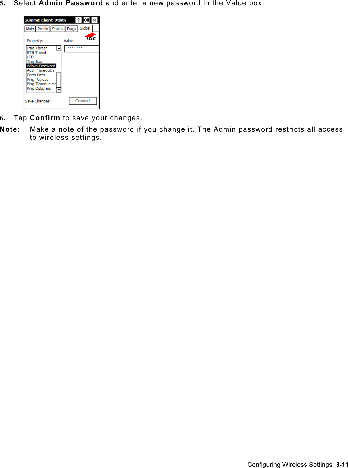
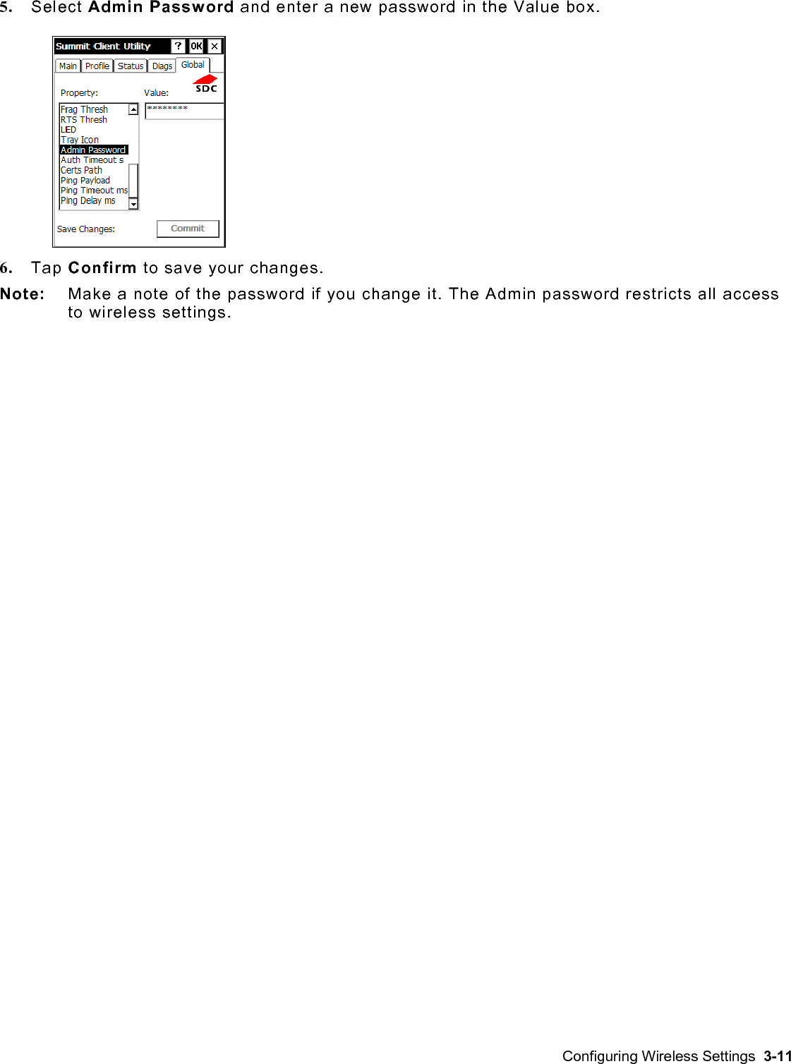
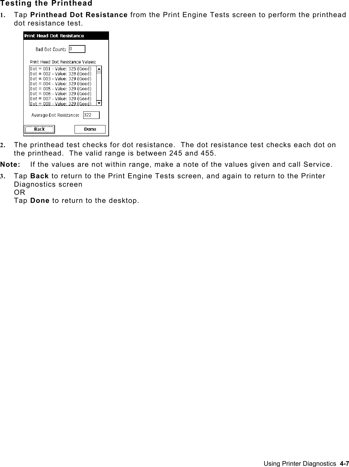
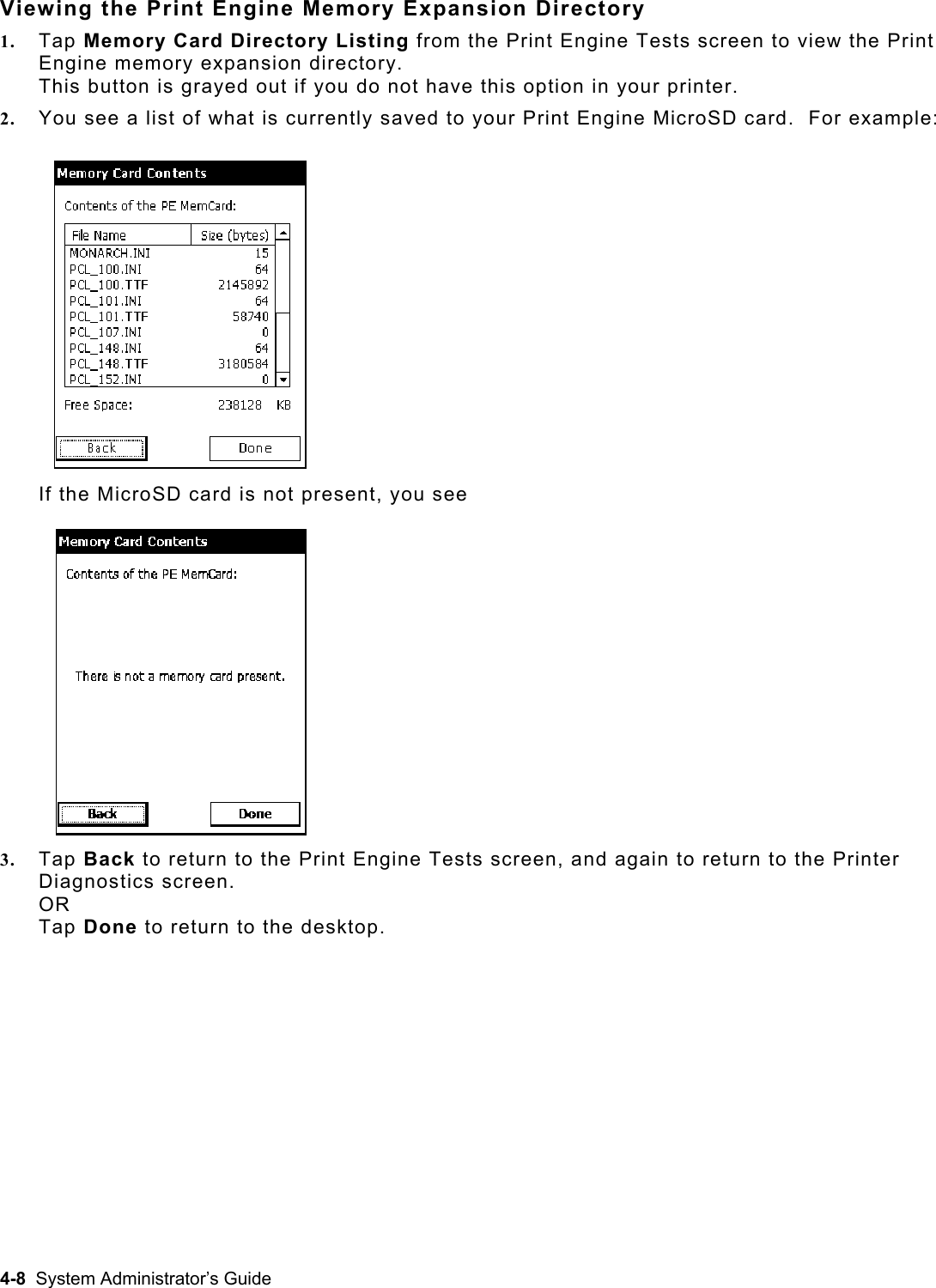
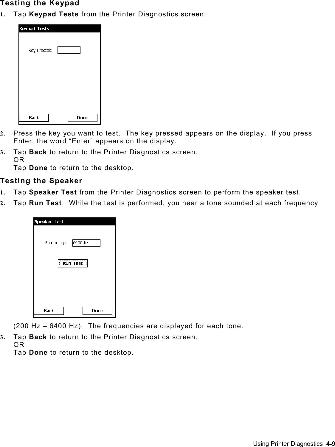
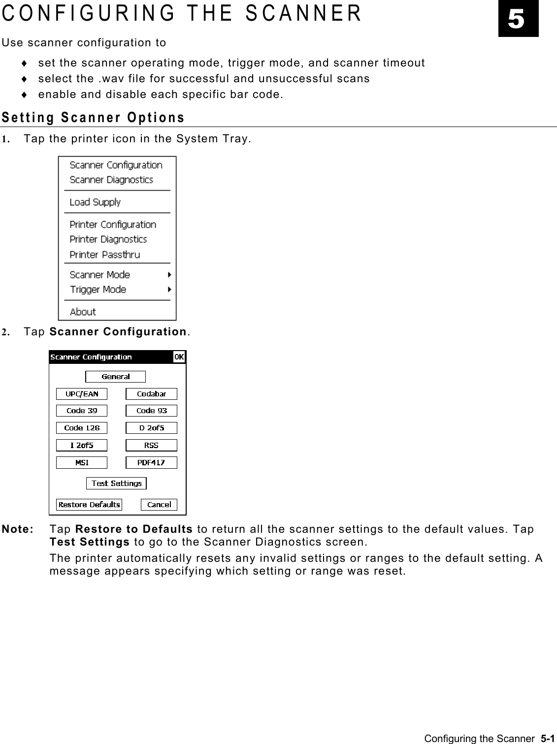
Avery Dennison Retail Information Services SDCCF20G Summit WLAN radio Module User Manual 6039sacv ah
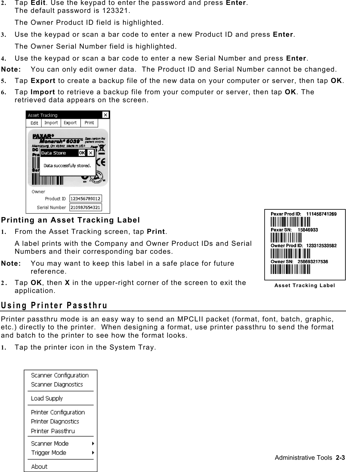
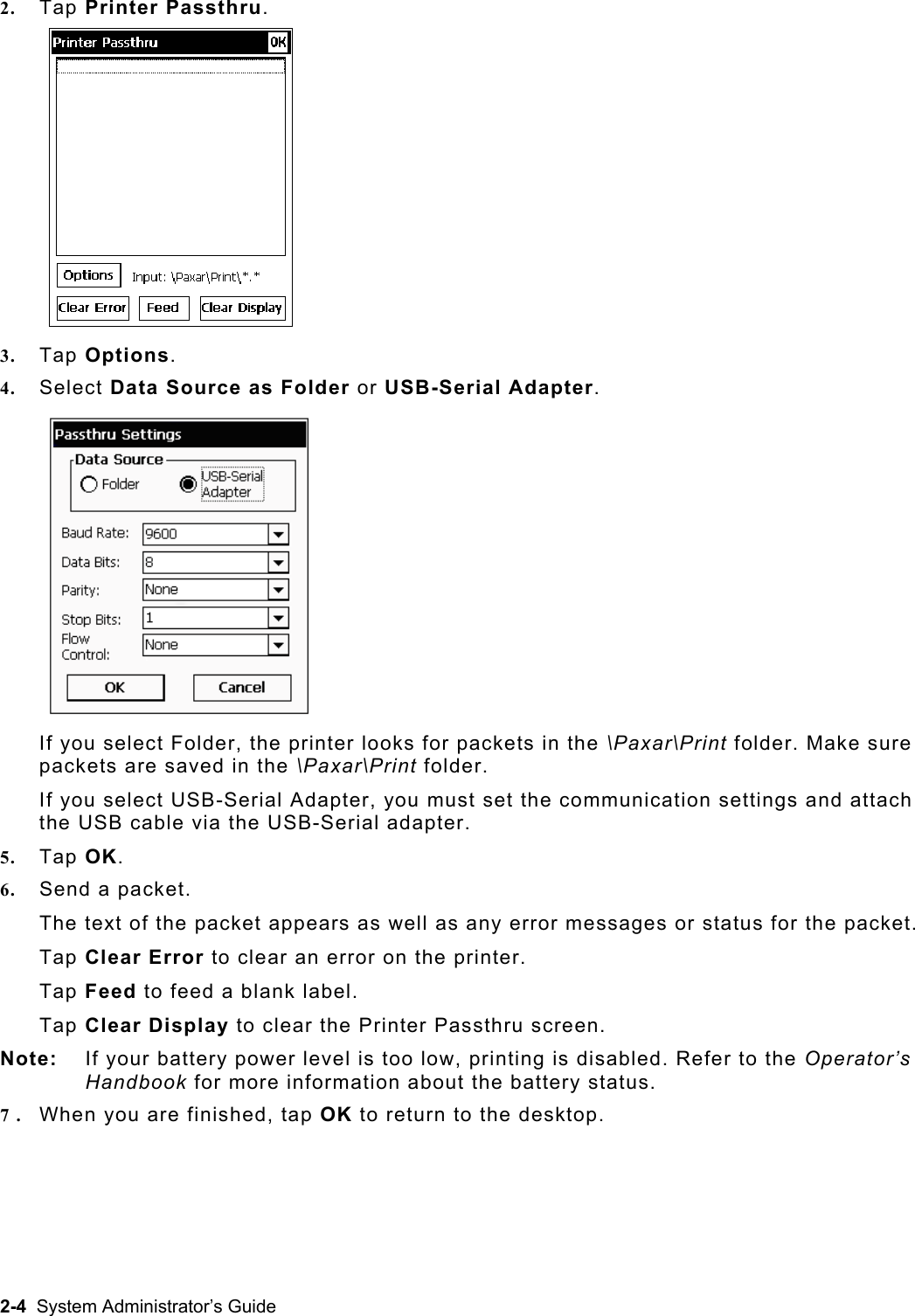
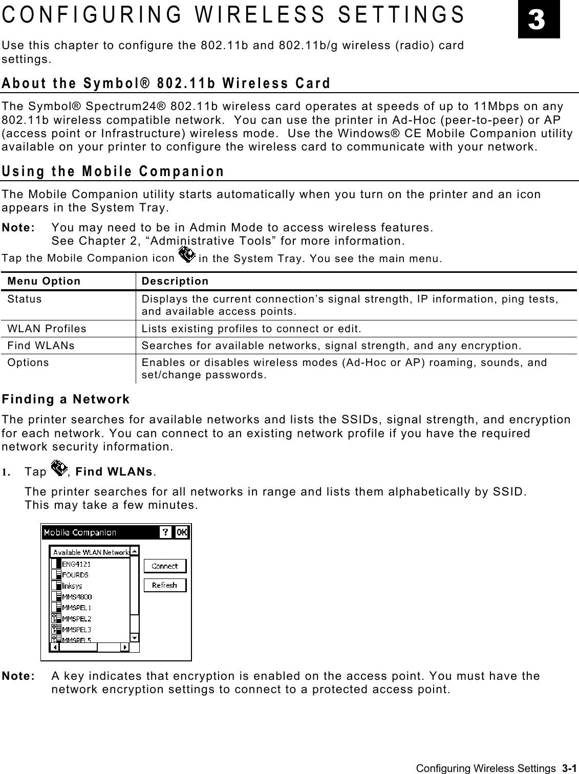
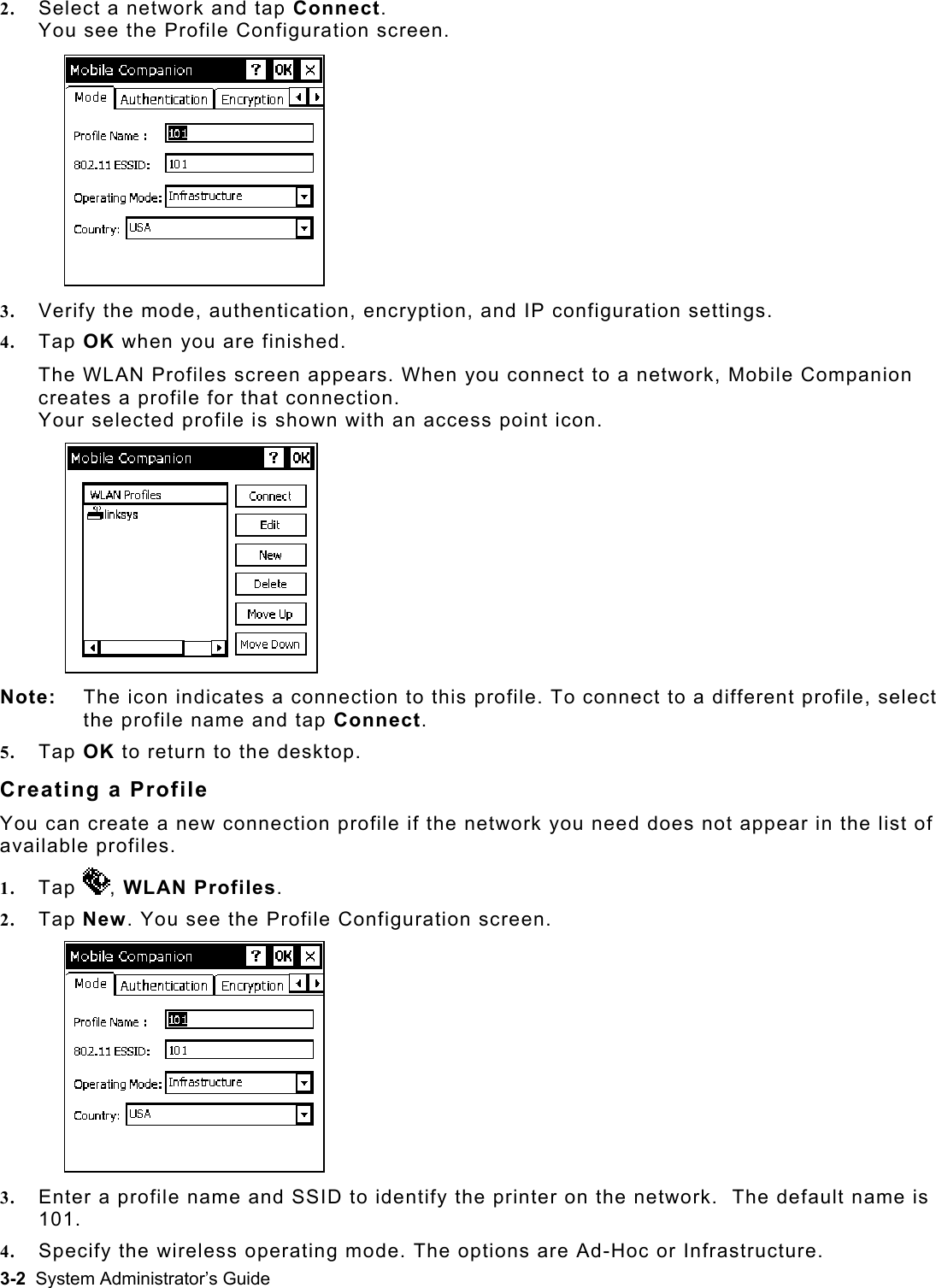
Avery Dennison Retail Information Services, LLC Summit WLAN radio Module 6039sacv ah
Contents
- 1. Module User Manual
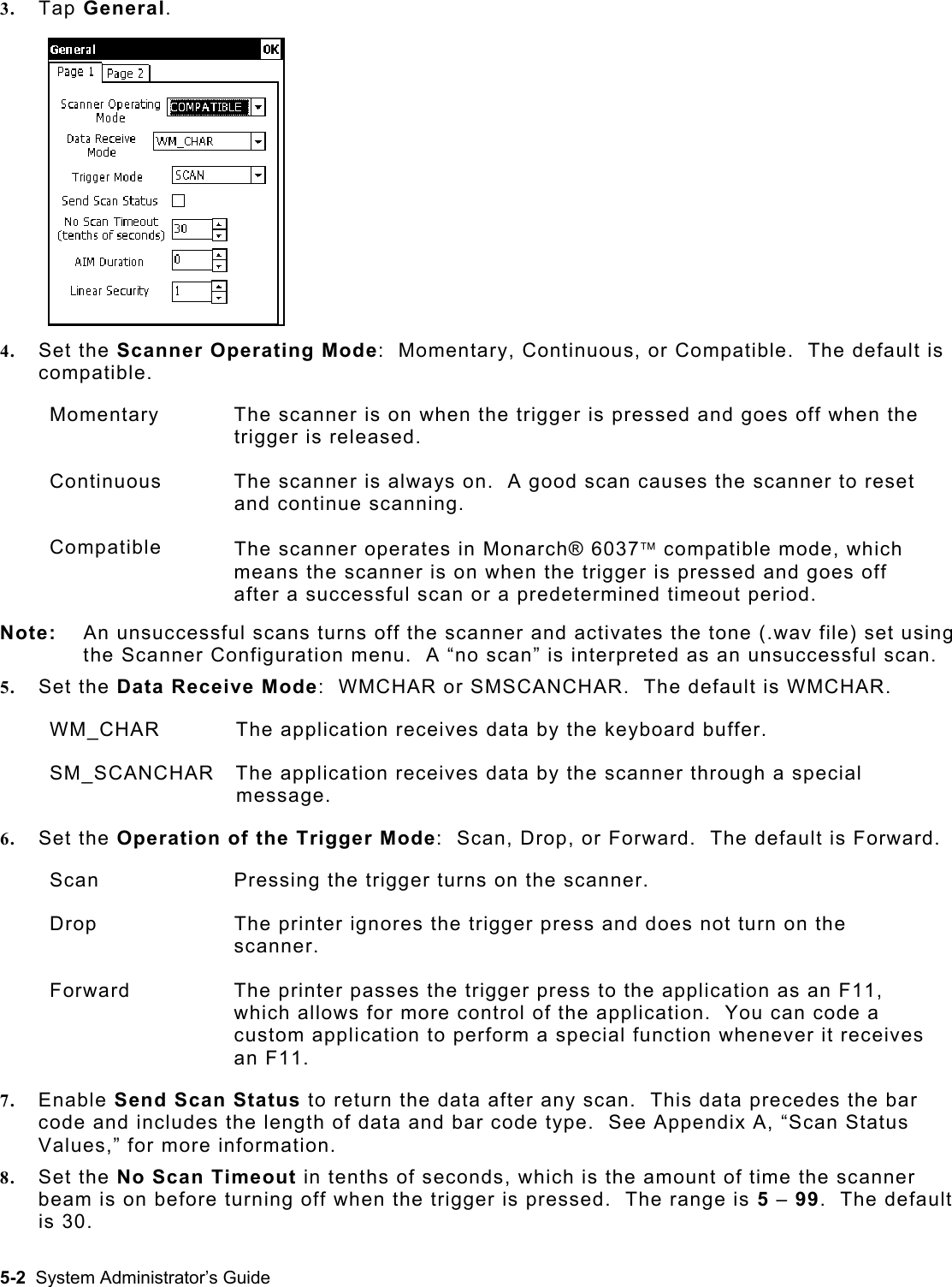
- 2. Host User Manual
- 3. Use manual Regulatory Info
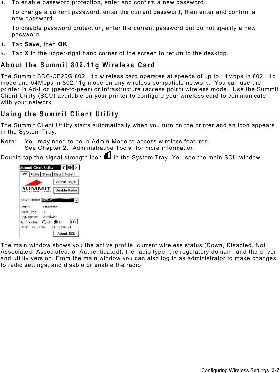
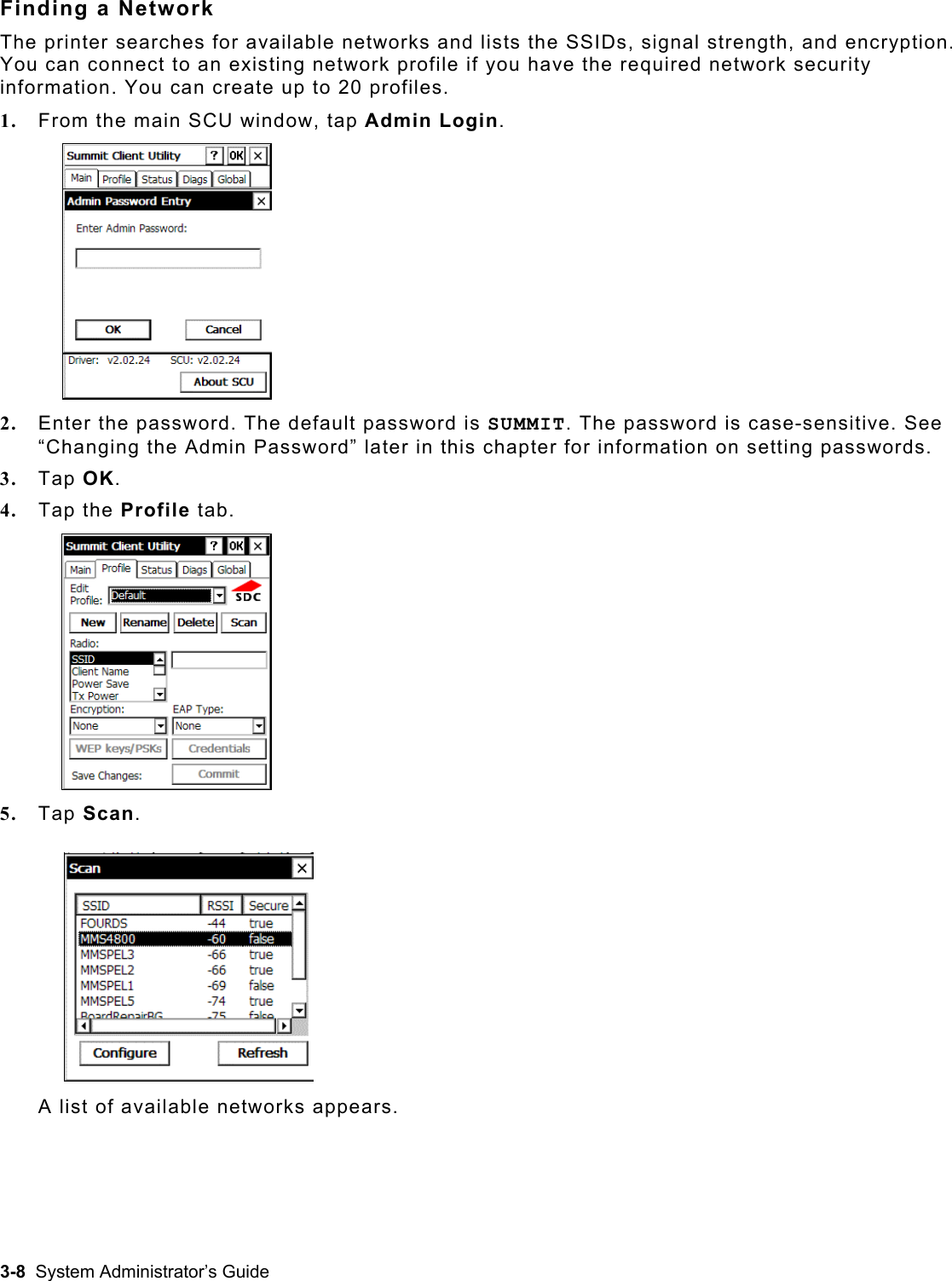
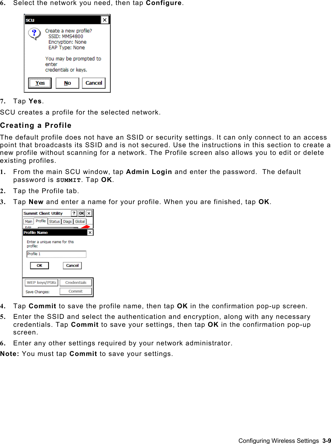
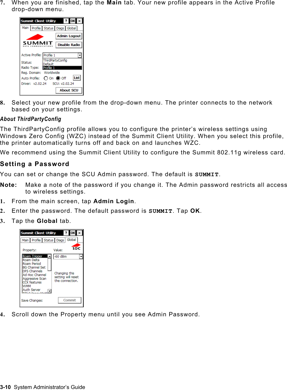
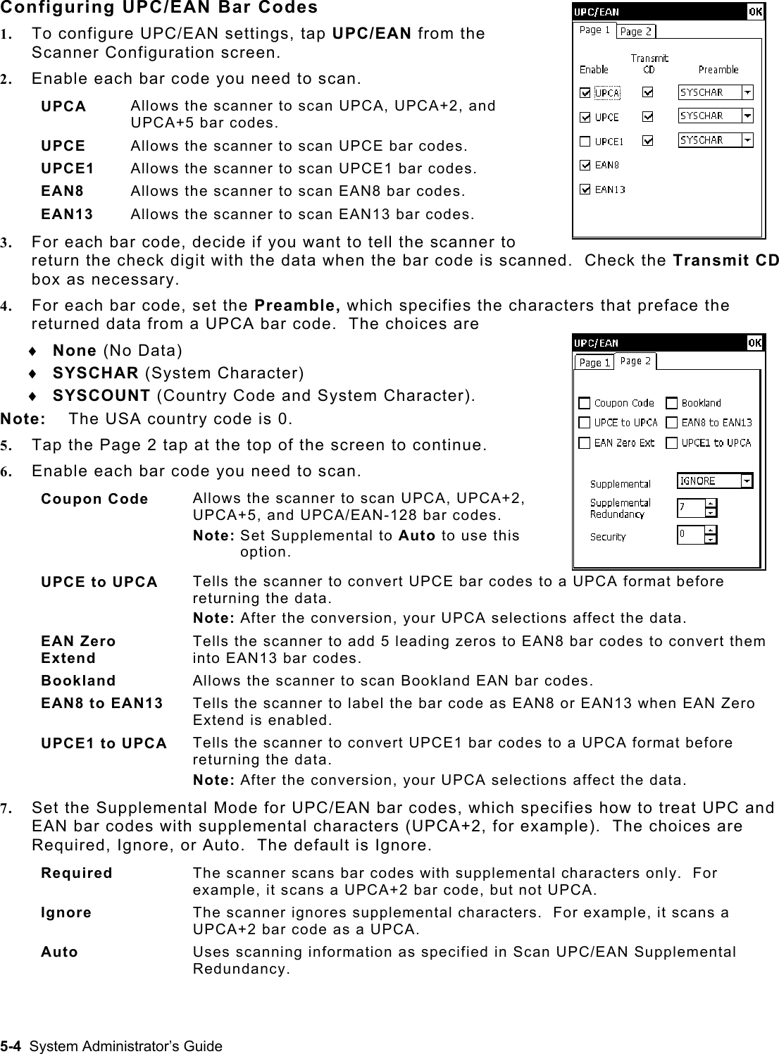
Host User Manual