Aviat Networks 3ECJ68W7P ISM Band Digital Radio User Manual CERTIFICATE OF COMPLIANCE
Aviat Networks ISM Band Digital Radio CERTIFICATE OF COMPLIANCE
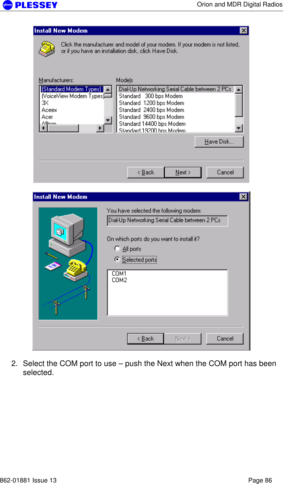
UserManual.wiki
>
Aviat Networks
>
3ECJ68W7P User Manual
Users Manual
Navigation menu
Upload a User Manual
Namespaces
Wiki Guide
HTML
PDF
Info
Views
User Manual
Discussion / Help
Navigation

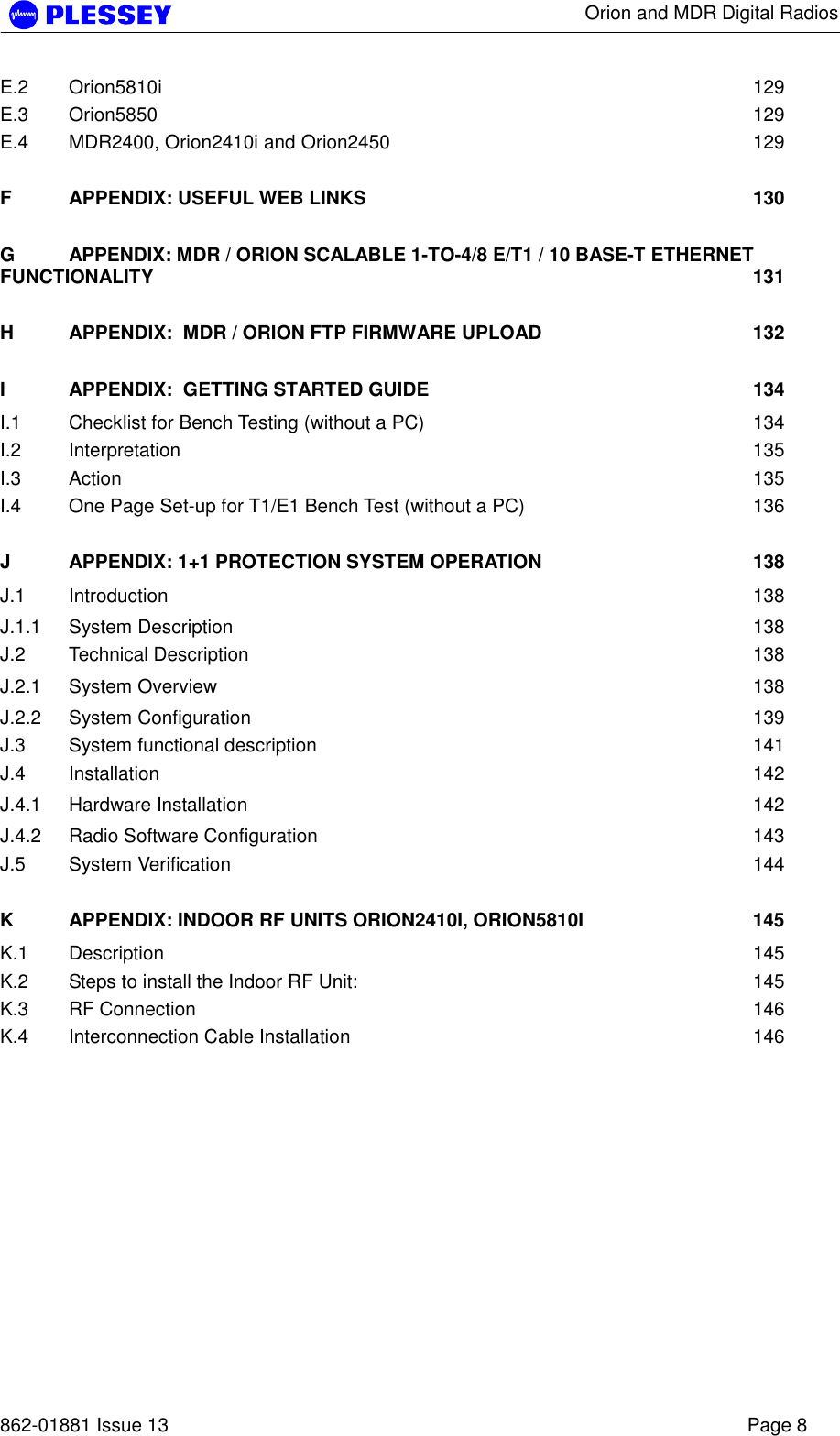

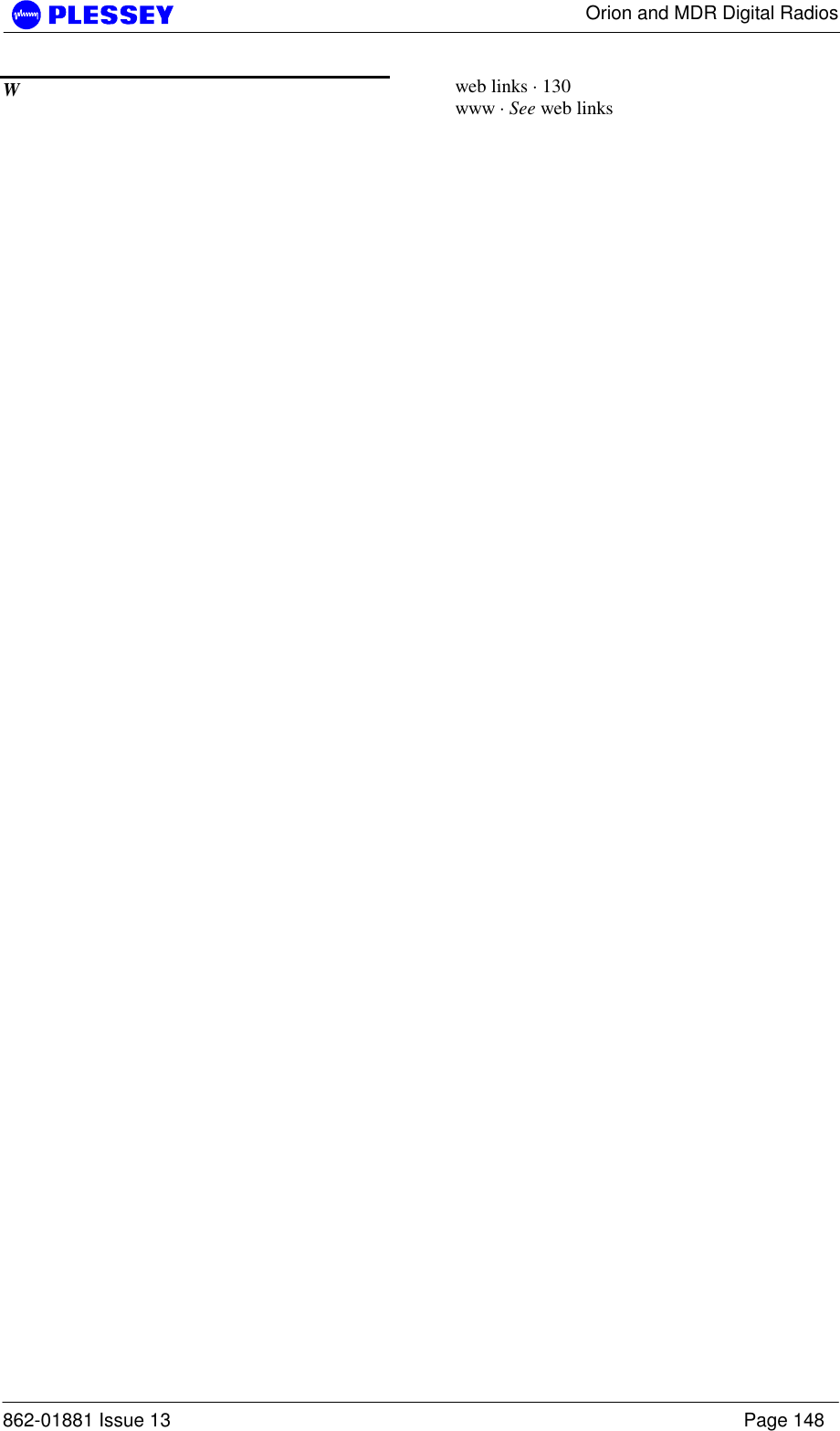
![Orion and MDR Digital Radios 862-01881 Issue 13 Page 15 8.46Mbps / 16-QAM 5801 5844 16.93 Mbps / 16-QAM 5802 5843 25.39 Mbps / 16-QAM 5804 5841 50.78 Mbps / 32-QAM 5806 5839 NOTE 1 Both RF Units in a link must be set to the same frequency channel plan (i.e. A, B, C or D) and modulator type. Also note that the frequencies differ for different transmit bandwidths, i.e. the frequency of channel A changes according to the transmit bandwidth. NOTE 2 Figure 4 reflects all the frequency bands that could be obtained with the ORION5850 RFU. Pre-programmed frequency ranges in the radio firmware prevent the user from selecting transmission options that will not meet FCC requirements. Frequency [MHz]5731 5774 5801 5844ABCABCLow Transmit Band High Transmit Band Figure 4. Orion 5850 Frequency channel plans A, B and C. Refer to NOTE 2 above with regards to FCC standards compliance of the different band plans. 2.2.1.5 Orion 2450 Frequency Channels Plan A, B and C (FCC Compliant) The channel spacing is based on the transmit bandwidth, either 3 MHz, 6 MHz, 10 MHz or 14 MHz, software selectable. Different bandwidths can be selected dependent on the optimum link performance; required system sensitivity versus data transfer rate. Only channel frequencies that are FCC compliant can be selected through the configuration software. The channel frequency ranges are programmed into the radio firmware and cannot be adjusted by the user. The radios were tested and approved for FCC compliance with the frequency ranges below, see Figure 4. Low band RF Unit: Modulation Type Lowest Center Freq. (MHz) Highest Center Freq. (MHz) 8.46Mbps / 16-QAM 2405 2429 16.93 Mbps / 16-QAM 2406 2428 25.39 Mbps / 16-QAM 2408 2426 50.78 Mbps / 32-QAM 2410 2424](https://usermanual.wiki/Aviat-Networks/3ECJ68W7P/User-Guide-385280-Page-16.png)
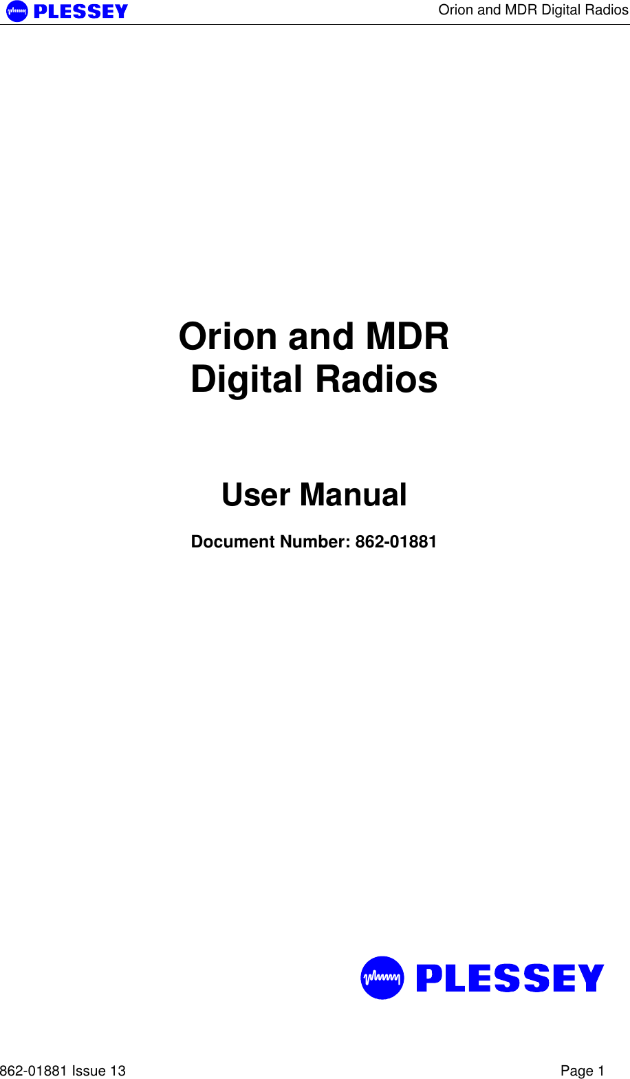
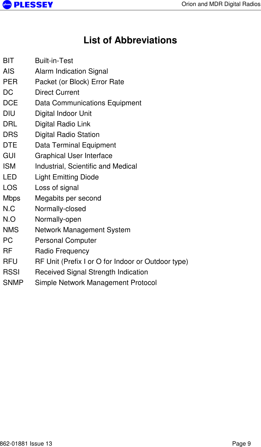
![Orion and MDR Digital Radios 862-01881 Issue 13 Page 16 High band RF Unit: Modulation Type Lowest Center Freq. (MHz) Highest Center Freq. (MHz) 8.46Mbps / 16-QAM 2444 2469 16.93 Mbps / 16-QAM 2445 2468 25.39 Mbps / 16-QAM 2447 2466 50.78 Mbps / 32-QAM 2451 2463 NOTE 1 Both RF Units in a link must be set to the same frequency channel plan (i.e. A, B, C or D) and modulator type. Also note that the frequencies differ for different transmit bandwidths, i.e. the frequency of channel A changes according to the transmit bandwidth. NOTE 2 Figure 4 reflects all the frequency bands that could be obtained with the ORION2450 RFU. Pre-programmed frequency ranges in the radio firmware prevent the user from selecting transmission options that will not meet FCC requirements. Frequency [MHz]2405 2429 2444 2469ABCABCLow Transmit Band High Transmit Band Figure 5. Orion 2450 Frequency channel plans A, B and C. 2.2.1.6 Frequency Channel Plan D (FCC Compliant) Frequency plan D allows independent control of transmit and receive frequencies. This allows a flexible frequency plan and can be used to overcome interference in the 2.4GHz and 5.8 GHz ISM bands. The frequencies that can be used in the lower or upper sub-bands can be selected in 1 MHz increments. Performance degradation can be expected when operating using channel plan D mode with the chosen frequencies close to the sub-band edges i.e. a choice of one of the high frequencies in the lower sub-band and one of the lower frequencies in the upper sub-band. The allocation of Channel plan D frequencies is shown in Table 4, Table 5 and Table 6.The Orion 24/5850 RF units have up to four different sets of minimum and maximum frequencies, which are determined by the data rate setting of the RFU. Only channel frequencies that are FCC compliant can be selected through the configuration software. The channel frequency ranges are programmed into the radio firmware and cannot be adjusted by the user.](https://usermanual.wiki/Aviat-Networks/3ECJ68W7P/User-Guide-385280-Page-17.png)
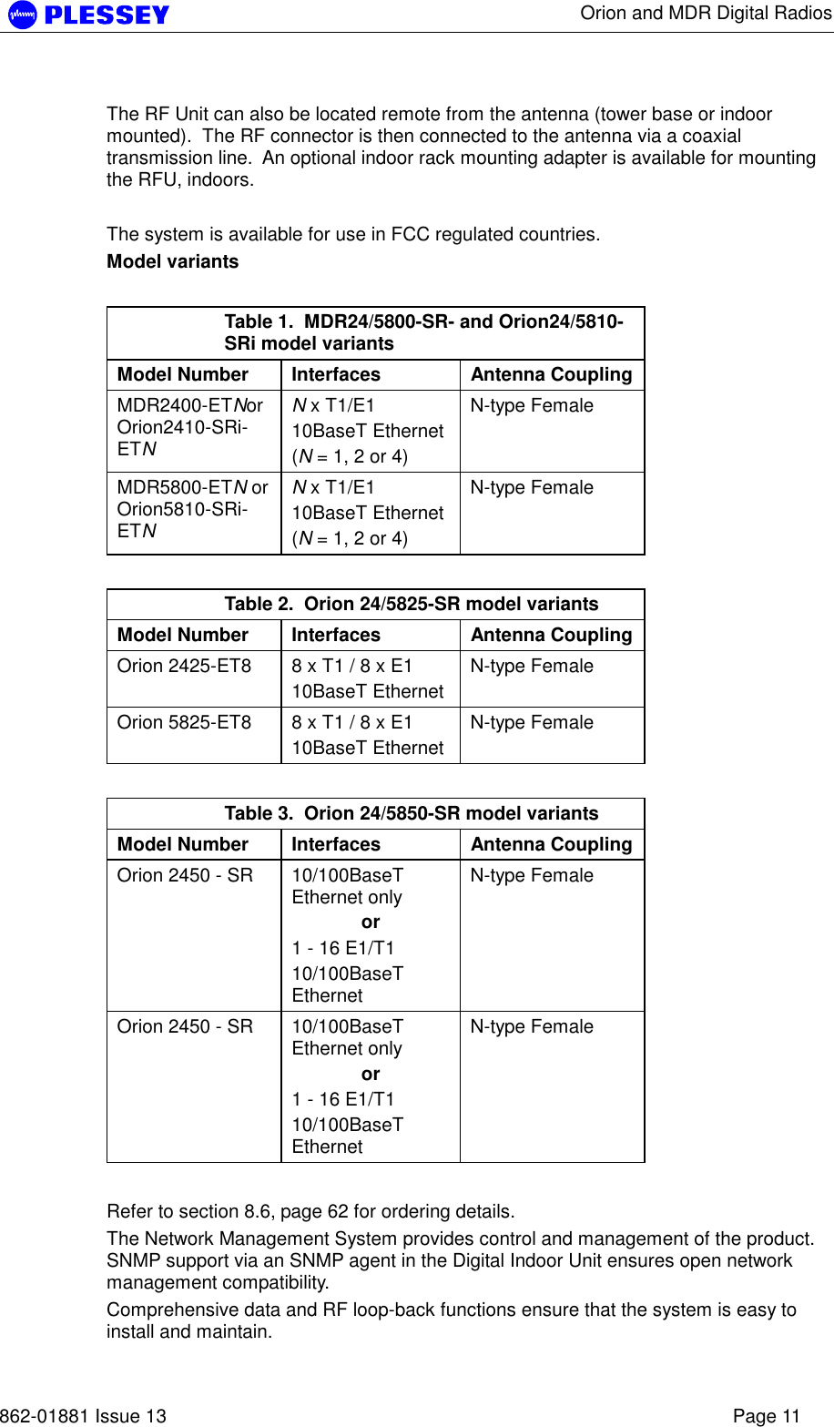
![Orion and MDR Digital Radios 862-01881 Issue 13 Page 17 The radios ware tested and approved for FCC compliance with the frequency ranges below, see Figure 4. Table 4. MDR2400 and Orion2410i Channel plan D channel frequencies Sub-band Center Frequency (MHz) L 2410-2426 H 2458-2474 NOTE the allowable operation range in FCC countries, page 14. Table 5. MDR5800 and Orion5810i Channel plan D channel frequencies Sub-band Center Frequency (MHz) L 5735-5771 H 5804-5840 Table 6. Orion 5850 Channel plan D channel frequencies Center Frequency (MHz) RF BW [MHz] / Data Rate [kbps] Lower Sub-band Upper / Higher Sub-band 2.6 / 8464 5731-5774 5801-5844 5.4 / 16928 5732-5773 5802-5843 8.0 / 25392 5734-5771 5804-5841 14.0 / 50784314 5769-5769 5806-5839 Table 7. Orion 2450 Channel plan D channel frequencies Center Frequency (MHz) RF BW [MHz] / Data Rate [kbps] Lower Sub-band Upper / Higher Sub-band 2.6 / 8464 2405-2429 2444-2469 5.4 / 16928 2406-2428 2445-2468 8.0 / 25392 2408-2426 2447-2466 14.0 / 50784314 2410-2424 2451-2463 2.2.1.7 Orion 24/5850 Modulator Types The Orion 24/5850 can operate with different modulator types, the trade-offs being better radio performance versus higher data throughput. The changes can be made via software, using either the Orion NMS / GUI or an SNMP client application.](https://usermanual.wiki/Aviat-Networks/3ECJ68W7P/User-Guide-385280-Page-18.png)
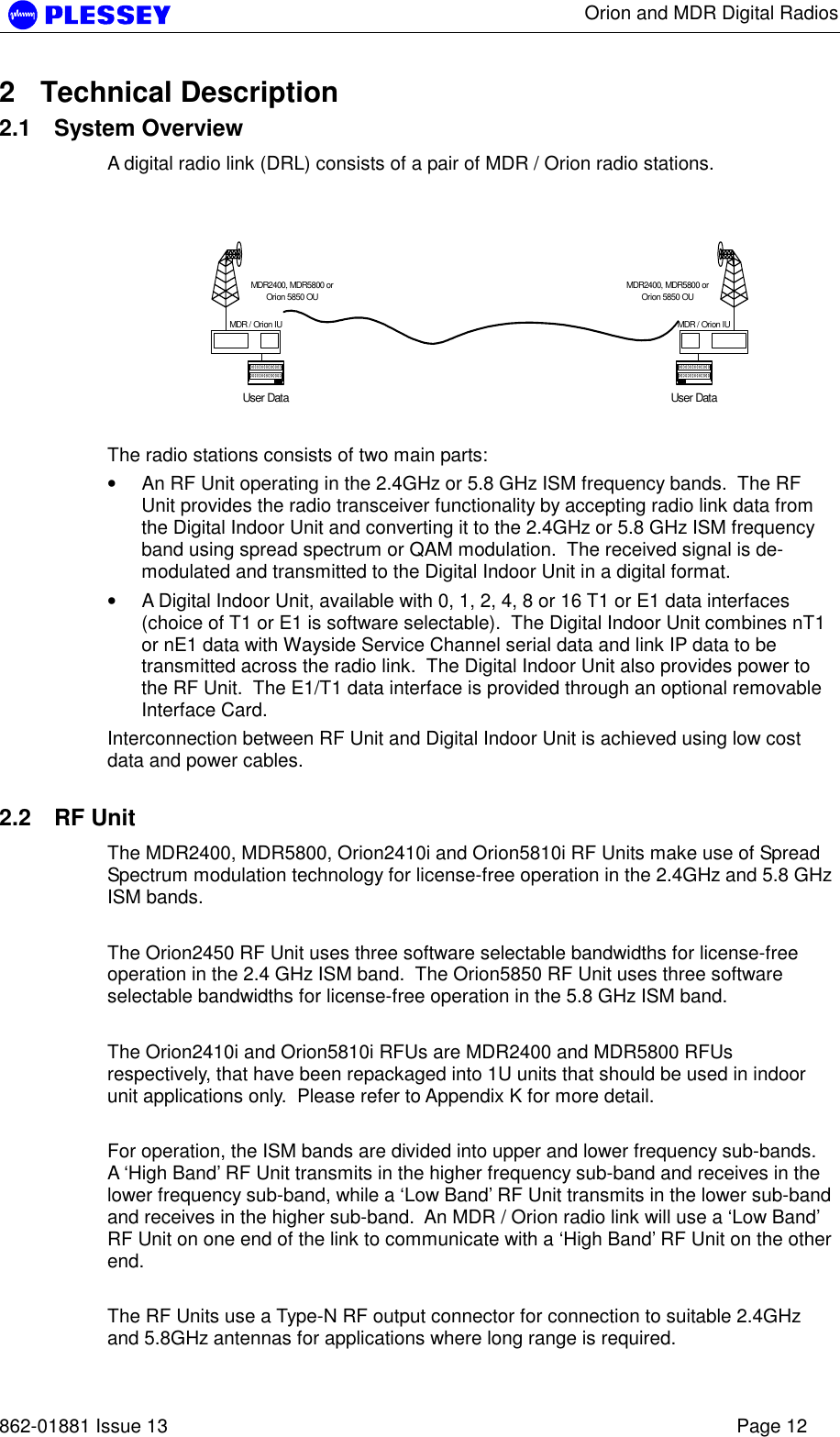
![Orion and MDR Digital Radios 862-01881 Issue 13 Page 18 Modulator types and frequency bands that were tested and approved for compliance with FCC regulations are specified in Sections 2.2.1.4 and 2.2.1.5. Table 8. Orion 24/5850 Modulator Types Data Rate [kbps] Modulation type Raw data throughput [bit/sec] Typical Payload Approx. RFU output spectrum BW 8464 16-QAM 8 464 052 4T1/E1 + 150kbit Ethernet 2.6 MHz 16928 16-QAM 16 928 105 8T1/E1 + 150kbit Ethernet 5.4 MHz 25392 16-QAM 25 392 157 8T1/E1 + 9.5Mbit Ethernet 8 MHz 50784314 32-QAM 50784314 46 Mbit/s Ethernet or 16 T1/E1 + 14 Mbit/s Ethernet 14 MHz NOTE 1: Changing the modulator type of an Orion 24/5850 RF Unit may take up to 30 seconds. During this period, the link will not be available. Changing the RFU modulator type does not support Auto Recovery thus; the modulator type of the remote station must be changed before the modulator type of the local station is changed. 2.2.2 RF Power Output Options The RF Unit is designed for use in countries that have adopted FCC standards. It is possible to adjust the output power on the RFU using the supplied NMS software or a SNMP Management application. The FCC standards for the MDR2400 unit require a limited output power as stated on page 2, U.S. only. NOTE 1 The firmware on the Orion and MDR type RFUs will not accept power level settings that fall outside the FCC compliant levels. 2.2.3 MDR24/5800, Orion24/5810i and Orion 24/5850 RF Units The RF Units transmit and receive RF signals through a diplexer interfaced via an RF cable to an external antenna. The unit has a type-N connector for connection to the RF cable used between the RFU and the antenna. The RF Unit houses the following main parts: a. Transmit/Receive Modules b. Baseband Modulator/Demodulator Circuitry c. Microcontroller/Framing & Buffering Circuitry d. Power Amplifier e. Diplexer](https://usermanual.wiki/Aviat-Networks/3ECJ68W7P/User-Guide-385280-Page-19.png)
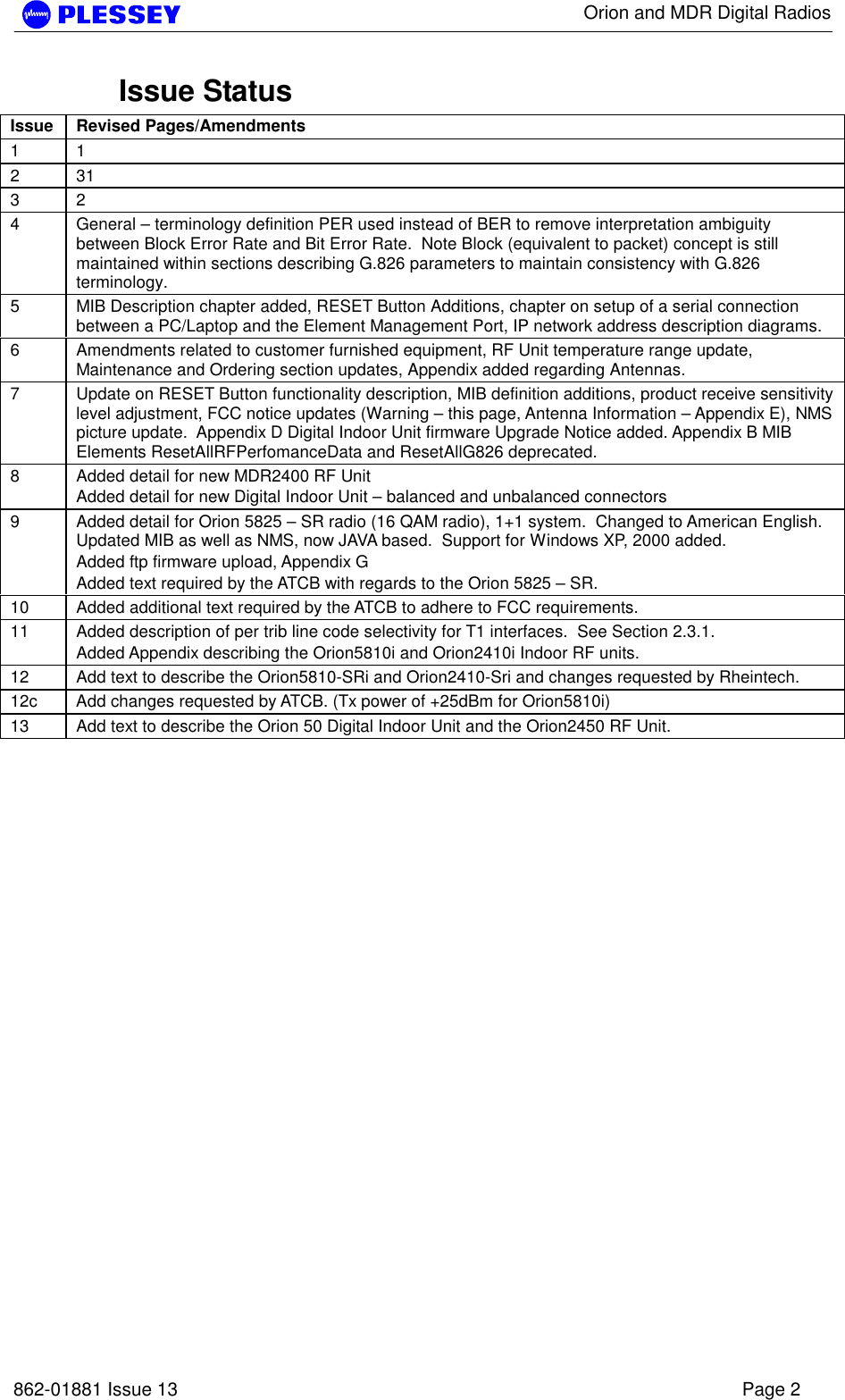
![Orion and MDR Digital Radios 862-01881 Issue 13 Page 43 5. Secure the antenna. 6. Measure the RSSI level and record the value (see section 5.6). 7. Compare with the value with that calculated for the link i.e. using the path loss calculation done when planning the link. Typical Version 2 MDR OU RSSI Voltage vs Received Signal Power (5.8GHz)0.40.60.811.21.4-80 -75 -70 -65 -60 -55 -50 -45 -40 -35 -30Received Signal Power [dBm]Outdoor Unit RSSI Voltage Figure 12. Typical Version 2 MDR5800 and Orion5810i RFU RSSI Voltage as a function of RF input power level -80 dBm Average 0.436 ± 0.029 V : MIB RSSI 95 ± 1 dBm (see comment below) -30 dBm Average 1.333 ± 0.047 V : MIB RSSI 54 ± 2 dBm (see comment below) The front panel RF Link LED, the Received Signal Strength Indicators (RSSI : on NMS, via SNMP or as an Electrical signal on the RF Unit), Carrier-detect (NMS, SNMP) and Frame Lock (NMS, SNMP) indicators are available to assist with link installation and alignment. NOTE 1 The MIB lists a value representative of the received signal level in [-dBm]. This value corresponds to the signal power measured in a 200 kHz BW centred at the receive frequency of the radio. When not in spectrum analyser mode, the Orion RFU translates the measured signal power to a value corresponding to the wanted signal power in the receiver bandwidth. NOTE 2 For the MDR and Orion10i RFUs, the RSSI values displayed in the MIB are representative of the signal level measured over a 200kHz BW. Add ~20dB to the MIB value for a wanted spread spectrum signal. The NMS / GUI will do this adjustment automatically and will therefore always display the correct RSSI value. NOTE 3 Due to the technique used to calculate the RSSI level of a wanted signal, the measured RSSI level can differ from the actual value with up to ±3 dB.](https://usermanual.wiki/Aviat-Networks/3ECJ68W7P/User-Guide-385280-Page-44.png)
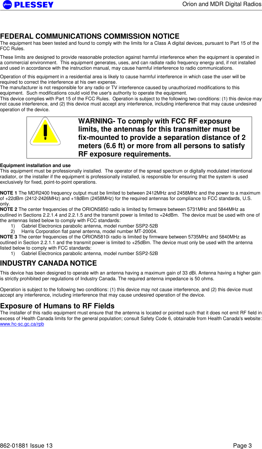
![Orion and MDR Digital Radios 862-01881 Issue 13 Page 44 Typical MDR2400 OU RSSI Voltage vs Received Signal Power0.60.811.21.41.61.8-100 -95 -90 -85 -80 -75 -70 -65 -60 -55 -50 -45 -40Received Signal Power [dBm]Outdoor Unit RSSI Voltage Figure 13. Typical MDR2400 and Orion2410i RFU RSSI Voltage as a function of RF input power level (See comment above.) Typical Orion OU RSSI Voltage vs Received Signal Power0.60.811.21.41.61.82-100 -95 -90 -85 -80 -75 -70 -65 -60 -55 -50 -45 -40 -35 -30Received Signal Power [dBm]Outdoor Unit RSSI Voltage Figure 14. Typical Orion 5850 RFU RSSI Voltage as a function of RF input power level (note the different bandwidths) 5.2.3 Set Transmitted Power Level It is good practice to match received power levels by adjusting transmitted powers if co-located systems are being installed. This is important to avoid interference between co-located systems. An attenuator can be fitted between the RF Unit and the antenna if the power level cannot be sufficiently reduced. The dBm output at the RFU N-type connector (socket) levels are set via the NMS or using a SNMP Management application.](https://usermanual.wiki/Aviat-Networks/3ECJ68W7P/User-Guide-385280-Page-45.png)
![Orion and MDR Digital Radios 862-01881 Issue 13 Page 47 5.6 MDR / Orion Test Record Parameter Unit Site A Site B Frequency channel plan: Transmit Receive NOTE 1 : C is NOT used for the MDR2400. NOTE 2 : FCC requirements (U.S. only), page 2. A/B/C/D A/B/C/D If D – List Transmit and Receive Frequencies [MHz] Transmitter output power (NOTE 2) dBm Receiver input level (ON) Volts Receiver input level (ON) dBm Receiver input level (OFF) Volts Receiver input level (OFF) dBm Calculated input level dBm Fade margin dB Frame Lock indicator Colour Fixed attenuator DB BER-test Hours BER Alarm Indicators Clear (Yes/No) Date Name Signature Performed by Approved by](https://usermanual.wiki/Aviat-Networks/3ECJ68W7P/User-Guide-385280-Page-48.png)


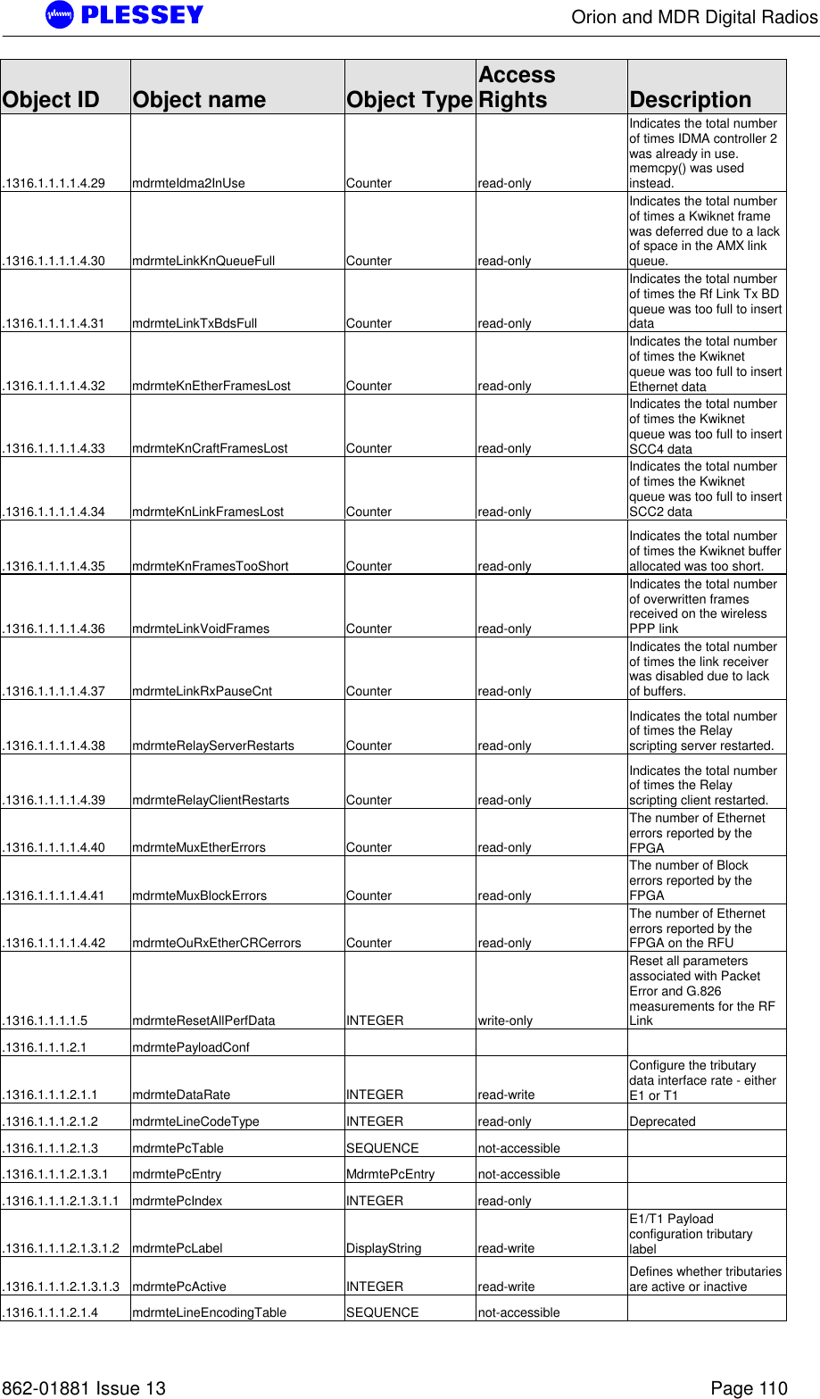
![Orion and MDR Digital Radios 862-01881 Issue 13 Page 111 Object ID Object name Object Type Access Rights Description .1316.1.1.1.2.1.4.1 mdrmteLineEncodingEntry MdrmteLineEncodingEntry not-accessible .1316.1.1.1.2.1.4.1.1 mdrmteLineEncodingIndex INTEGER read-only .1316.1.1.1.2.1.4.1.2 mdrmteLineEncodingTribSelect INTEGER read-only Selects the trib, or group of tributaries to which encoding applies .1316.1.1.1.2.1.4.1.3 mdrmteLineEncoding INTEGER read-write Defines the line code types for the tributaries, either HDB3 or AMI for E1 .1316.1.1.1.2.2 mdrmteRFLinkConf .1316.1.1.1.2.2.1 mdrmteTxPower INTEGER read-write Allows setup of the output power available at the diplexer port of the RF Unit .1316.1.1.1.2.2.2 mdrmteBandPlan INTEGER read-write The MDR5800 RF Units operate in the 5.725 GHz to 5.850 GHz ISM frequency band. .1316.1.1.1.2.2.3 mdrmteTxFrequencyPlanD INTEGER read-write Frequency plan D allows independent control of transmit and receive frequencies. .1316.1.1.1.2.2.4 mdrmteRxFrequencyPlanD INTEGER read-write Refer to the mdrmteTxFrequencyPlanD description .1316.1.1.1.2.2.5 mdrmteTransmitBand INTEGER read-only This value is read from the RF Unit via the Digital Indoor Unit and defines whether it transmits in the .1316.1.1.1.2.2.6 mdrmteReserved2 INTEGER read-write .1316.1.1.1.2.2.7 mdrmteRegulations INTEGER read-only This parameter is read from the RF Unit via the Digital Indoor Unit and defines regulatory compliance of the RF Unit .1316.1.1.1.2.2.8 mdrmteAutoRecovery INTEGER read-write This feature is used if the user is installing a link from one side and there is no assistance on the opposite side of the link. It mitigates against the link failing and not being able to be .1316.1.1.1.2.2.9 mdrmteOURateOverride INTEGER read-write Depracated .1316.1.1.1.2.2.10 mdrmteOUDataRate INTEGER read-write A setable rate that allows a reduced transfer data rate over the RF Link .1316.1.1.1.2.2.11 mdrmteTxFrequencyCurrent INTEGER read-only This value [MHz] is read back from the RF Unit and defines the transmit frequency of the RF Unit .1316.1.1.1.2.2.12 mdrmteRxFrequencyCurrent INTEGER read-only This value [MHz] is read back from the RF Unit and defines the receive frequency of the RF Unit .1316.1.1.1.2.2.13 mdrmteNonAutoBandPlan INTEGER read-write Same as mdrMTEBandPlan setting in this MIB group except Autorecovery is not enabled - this allows control of the Outdoor .1316.1.1.1.2.2.14 mdrmteNonAutoTxFreqPlanD INTEGER read-write Same as mdrTxFrequencyPlanD setting in this MIB group except autorecovery is not enabled - this allows control of the Outdoor](https://usermanual.wiki/Aviat-Networks/3ECJ68W7P/User-Guide-385280-Page-112.png)