Aviat Networks ODU600HB Eclipse ODU600 User Manual Eclipse
Aviat Networks (S) Pte. Ltd Eclipse ODU600 Eclipse
Contents
- 1. Installation Manual
- 2. User Manual
User Manual

Eclipse ODU 600
Installation Manual
5.8 GHz Unlicensed Band
Manual Rev. 001
August 2013

ECLIPSE INSTALLATION MANUAL
260-668066-004 AUGUST 2013 II
Copyright & Terms of Use
August 2013
This manual is specific to Eclipse with ODU 600 for split-mount operation on the
FCC and Industry Canada 5.8 GHz unlicensed band.
Copyright © 2013 by Aviat Networks, Inc.
All rights reserved.
No part of this publication may be reproduced, transmitted, transcribed, stored in a
retrieval system, or translated into any language or computer language, in any form
or by any means, electronic, magnetic, optical, chemical, manual or otherwise,
without the prior written permission of Aviat Networks Inc.
To request permission, contact techpubs@aviatnet.com.
Warranty
Aviat Networks makes no representation or warranties with respect to the contents
hereof and specifically disclaims any implied warranties or merchantability or fitness
for any particular purpose.
Further, Aviat Networks reserves the right to revise this publication and to make
changes from time to time in the content hereof without obligation of Aviat Networks
to notify any person of such revision or changes.
Safety Recommendations
The following safety recommendations must be considered to avoid injuries to persons
and/or damage to the equipment:
1. Installation and Service Personnel: Installation and service must be carried out by
authorized personnel who have the technical training and experience necessary to be
aware of any hazardous operations during installation and service, and of measures to
avoid any danger to themselves, to any other personnel, and to the equipment.
2. Access to the Equipment: Access to the equipment in use must be restricted to ser-
vice personnel only.
3. Safety Norms: Recommended safety norms are detailed in the Health and Safety
sections of this manual.
lLocal safety regulations must be used if mandatory. Safety instructions in this
document should be used in addition to the local safety regulations.
lIn the case of conflict between safety instructions stated in this manual and
those indicated in local regulations, mandatory local norms will prevail.
lShould local regulations not be mandatory, then the safety norms in Volume 1
will prevail.

ECLIPSE INSTALLATION MANUAL
III AVIAT NETWORKS
4. Service Personnel Skill: Service personnel must have received adequate technical
training on telecommunications and in particular on the equipment this manual
refers to.
Trademarks
All trademarks are the property of their respective owners.
CAUTION:Making adjustments and/or modifications to this equipment
that are not in accordance with the provisions of this instruction
manual or other supplementary documentation may result in personal
injury or damage to the equipment, and may void the equipment war-
ranty.

ECLIPSE INSTALLATION MANUAL
260-668066-004 AUGUST 2013 IV
Aviat Networks Support
Service and Technical Support:
For customer service and technical support, contact one of the regional Technical Help
Desks listed below, or for 24/7 (all day, every day of the year) there is the Global Tech-
nical Help Desk (GTHD).
The GTHD number is: +1-210-526-6345, or toll free 1-800-227-8332
within USA
lFor 24/7 access you will need your Support Assurance PIN. Without a PIN you
will still receive support, but the support process will require an additional
screening step.
lAfter-hours calls to Paris are routed to the GTHD. The Paris number is manned
during business hours.
Americas Technical Help
Desk
EMEA Technical Help Desk Asia Pacific Technical Help
Desk
Aviat Networks
5200 Great America Parkway
Santa Clara CA 95054
U.S.A.
Aviat Networks
4 Bell Drive
Hamilton International
Technology Park
Blantyre, Glasgow, Scotland
G72 0FB
United Kingdom
Aviat Networks
Bldg 10, Units A&B
Philexcel Industrial Park
M. Roxas Hi-way
Clark Freeport Zone
Philippines 2023
Toll Free (Canada/USA): 800
227 8332
Phone: 210 561 7400
Fax: 210 561 7399
Phone:
Hamilton: +44 (0) 1698 717 230
Paris: +33 (0) 1 77 31 00 33
Fax: +44 (0) 1698 717 204
Phone: +63 45 599 5192
Fax: +63 45 599 5196
TAC.AM@aviatnet.com TAC.EMEA@aviatnet.com TAC.APAC@aviatnet.com
Or you can contact your local Aviat Networks office. Contact information is available
on our website at: http://www.aviatnetworks.com/services/customer-sup-
port/technical-assistance/

ECLIPSE INSTALLATION MANUAL
V AVIAT NETWORKS
Eclipse Product Compliance Notes
Eclipse has been tested for and meets EMC Directive 2004/108/EC. The equipment
was tested using screened cable; if any other type of cable is used, it may violate com-
pliance.
Eclipse is a Class A product. In a domestic environment this product may cause radio
interference in which case the user may be required to take adequate measures. This
equipment is intended to be used exclusively in telecommunications centers.
Regulatory Information for the ODU 600, 5.8GHz Band
FCC Notices
1. The ODU 600, 5.8GHz must be professionally installed and maintained.
2. This equipment has been tested and found to comply with the limits for a
Class A digital device, pursuant to Part 15 of the FCC rules. These limits are
designed to provide reasonable protection against harmful interference when
the equipment is operated in a commercial environment. This equipment
generates, uses and can radiate radio frequency energy and, if not installed
and used in accordance with the instruction manual, may cause harmful
interference to radio communications. Operation of this equipment in a
residential environment is likely to cause harmful interference in which case
the user will be required to correct the interference at his own expense.
3. ODU 600, 5.8GHz is compliant with FCC CFR47, Part 15.247.
4. To ensure compliance with the FCC RF exposure requirements, a minimum
distance of 18 meters must be maintained between the antenna and any
persons whilst the unit is operational. This calculation is based on the
maximum conducted power and maximum antenna gain.
5. ODU 600, 5.8GHz has been certified for use with a parabolic antenna with a
maximum gain of 45.9dBi or a flat panel antenna with a maximum gain of
28dBi.
6. The software provided with this product allows for transmission only in the
frequency range 5725 – 5850MHz to ensure compliance with Part 15.247.
7. According to the conducted power limit in FCC CFR 47, Part 15.247, the
power for this device has been limited to 1W (30dBm) at the antenna port.
8. FCC CFR47, Part 15.247 excludes the use of point-to-multipoint systems,
omnidirectional applications and multiple co-located intentional radiators.
This system is only for fixed, point-to-point operation.
Industry Canada Notices Avis d’Industrie Canada
1. The ODU 600, 5.8GHz must be professionally installed and maintained.
2. ODU 600, 5.8GHz is compliant with Industry Canada RSS-210.

ECLIPSE INSTALLATION MANUAL
260-668066-004 AUGUST 2013 VI
3. To ensure compliance with the Industry Canada RF exposure requirements in
RSS-102, a minimum distance of 18 meters must be maintained between the
antenna and any persons whilst the unit is operational. This calculation is
based on the maximum conducted power and maximum antenna gain.
4. ODU 600, 5.8GHz has been certified for use with a parabolic antenna with a
maximum gain of 45.9dBi or a flat panel antenna with a maximum gain of
28dBi.
5. The software provided with this product allows for transmission only in the
frequency range 5725 – 5850MHz to ensure compliance with the Canadian
band edges.
6. According to the conducted power limit in RSS-210 Annex 8, the power for
this device has been limited to 1W (30dBm) at the antenna port.
Avis d’Industrie Canada
1. L’ODU 600, 5,8 GHz doit être mis en oeuvre et maintenu par des
professionnels.
2. L’ODU 600, 5,8 GHz est conforme à la spécification RSS-210 d’Industrie
Canada.
3. Pour assurer la conformité aux exigences d’exposition de la spécification RSS-
102 d’Industrie Canada, une distance minimum de 18 mètres entre l’antenne
et toute personne doit être assurée quand l’équipement est en fonctionnement.
Ce calcul est basé sur la puissance émise maximum et le gain maximum de
l’antenne.
4. L’ODU 600, 5,8 GHz a été homologué avec utilisation d’une antenne
parabolique de gain maximum 45,9 dBi ou d’une antenne plane de gain
maximum 28 dBi.
5. Le logiciel fournit avec ce produit permet la transmission dans la bande de
fréquences 5 725 – 5 850 MHz seulement, afin d’assurer la conformité avec les
limites de la bande canadienne.
6. En conformité avec la limite de puissance émise de la spécification RSS-210
Annexe 8, la puissance de cet équipement a été limitée à 1 W (30 dBm) à
l’accès de l’antenne.
International Use of 5.8GHz
This system does not employ DFS and, as such, the equipment cannot be deployed
within Europe or any country where DFS is a regulatory requirement for protection of
radars.
WEEE Directive
In accordance with the WEEE Directive (2002/96/EC), Eclipse is marked with the fol-
lowing symbol:

ECLIPSE INSTALLATION MANUAL
VII AVIAT NETWORKS
This symbol indicates that this equipment should be collected separately for the pur-
poses of recovery and/or recycling.
For information about collection and recycling of Aviat Networks equipment please
contact your local Aviat Networks sales office. If you purchased your product via a dis-
tributor please contact the distributor for information regarding collection and recov-
ery/recycling.
More information on the WEEE Directive is available at our website:
http://www.aviatnetworks.com/products/compliance/weee/.
(WEEE is the acronym for Waste Electrical and Electronic Equipment)
RoHS Directive
The RoHS (Restriction of Hazardous Substances) Directive (2002/95/EC) was imple-
mented on 1 July, 2006. Eclipse meets the requirements of this directive, as at the
implementation date.
Date of Manufacture
Eclipse date of manufacture information is controlled by serial number. Please contact
the Aviat Networks helpdesk for information regarding serial number format and date
of manufacture.

ECLIPSE INSTALLATION MANUAL
260-668066-004 AUGUST 2013 VIII
Contents
Copyright & Terms of Use ii
Aviat Networks Support iv
Eclipse Product Compliance Notes v
Regulatory Information for the ODU 600, 5.8GHz Band v
WEEE Directive vi
RoHS Directive vii
Date of Manufacture vii
Contents viii
VOLUME I: INTRODUCTION AND SAFETY 1
About the Documentation 3
Documentation Conventions and Terminology 3
Chapter 1. Health and Safety 5
General Health and Safety 6
Operator Health and Safety 7
General Hazards 8
Routine Inspection and Maintenance 11
Routine Inspections 11
Trend Analysis 11
Fault Analysis 12
Training 12
Spares 12
VOLUME II: SYSTEM OVERVIEW 13
Chapter 1. System Overview 15
Eclipse Node 17
INU 17
INUe 17
Plug-in Cards 18
Plug-in Cards Overview 19
Data Packet Plane 24
Adaptive Coding and Modulation (ACM) 24
Adaptive Modulation (AM) 25
Coding 25
Platforms 26
Platform Layout 26
Slot Assignments 27
ODU 600 for 5.8 GHz ISM Band 28

ECLIPSE INSTALLATION MANUAL
IX AVIAT NETWORKS
5.8 GHz Unlicensed Band 28
Protection Options 30
Link/Path Protection 30
Interface Protection 30
Network/Data Protection 31
Platform Protection 31
Licensing 33
Capacity Licensing 33
Node Feature Licensing 33
Node Feature Overview 33
Configuration and Management 36
Antennas 37
Power Supply 38
VOLUME III: INSTALLATION 39
Chapter 1. Introduction to Installation 41
Installation Overview 41
Installation Tools and Materials 42
Unpacking 42
Chapter 2. ODU Installation 43
Installing the Antenna 44
Installing a Coupler 45
Coupler Overview 45
Coupler Installation Procedure 45
Attaching a Direct-Mounted Coupler 45
Unused and Disconnected Coupler Ports 47
Installing the ODU 49
Direct-Mounted ODU Installation 49
Overview 49
Setting the Polarization 50
Direct-Mount ODU Attachment Procedure 52
Remote-Mounted ODUs 53
Remote-Mount Overview 53
Remote-Mount Installation Procedure 55
Waveguide Flange Data: ODUs 56
Grounding the ODU 56
Installing ODU Cables and Connectors 58
ODU Cable Options 58
Coaxial Cable Installation Requirements 59
ODU Cable Grounding 60
TypeN Cable Connectors 62
Jumper Cables 62
Installing Lightning Surge Arrestors 63
Lightning Arrestor Kit 63
Arrestor Installation at Building Entry 64

ECLIPSE INSTALLATION MANUAL
260-668066-004 AUGUST 2013 X
Bulkhead Installation Procedure: Grounded Copper Entryway Plate 64
Bulkhead Installation Procedure: Non-grounded / Non-master Entryway Plate 66
Building Entry Installation 67
Arrestor Installation at the ODU 68
Weatherproofing 69
Mastic Tape 69
Wrapping Guidelines, Mastic (Butyl) Tape 69
Self Amalgamating Tape 70
Wrapping Guidelines, Amalgamating Tape 70
Chapter 3. INU and INUe Installation 71
INU/INUe Overview 72
Front Panel Layout 72
Power Supply 72
Power Consumption and INU Load Maximums 73
PCC +24 Vdc Operation 75
Power Cables 76
Fuses 77
Installation Requirements 78
Installation Procedure 80
Plug-in Installation 83
INU/INUe Cable Assemblies 86
DAC Trib Connectors and Cables 86
DAC 16xV2 Cable and Connector Data 86
DAC 4x Cable and Connector Data 92
DAC GE3 Ethernet RJ-45 Cables 94
DAC Optical Cable and Connector Data 95
DAC 155eM Cables 97
NMS Connectors and Cables 97
NMS 10/100Base-T Connector 97
Maintenance V.24 Connector 98
Auxiliary and Alarm Connectors and Cables 99
AUX Data Cable: Async, HD26 to Wirewrap, 2m 99
AUX Data Cable: Sync, HD26 to Wirewrap, 2m 100
AUX Data Cable: Async, HD26 to 3 X DB9, 1m 101
AUX Data Cable: Sync, HD26 to 3 X DB9, 1m 102
AUX Data Cable: Async, AUX HD26 to AUX HD26, 1m 103
AUX Data Cable: Sync, AUX HD26 to AUX HD26, 1m 104
AUX Alarm I/O Cable: HD15 to Wirewrap, 2m or 5m 105

ECLIPSE INSTALLATION MANUAL
Volume I: Introduction and Safety
260-668066-004 AUGUST 2013 1

VOLUME I, CHAPTER 0, INTRODUCTION AND SAFETY
2 AVIAT NETWORKS

ECLIPSE INSTALLATION MANUAL
About the Documentation
This documentation provides information on the installation of an Eclipse
Microwave Radio system comprising the INU/INUe and ODU 600 for operation on
the 5.8 GHz unlicensed band in USA and Canada.
Intended Audience
This information is for use by trained technicians or engineers. It does not provide
information or instruction on basic technical procedures. Aviat Networks recom-
mends you read the relevant sections of this manual thoroughly before beginning
any installation or operational procedures.
Organization
This manual is divided into the following sections:
lHealth and Safety Requirements
lSystem Overview
lInstallation
Additional Resources
The resources identified below contain additional information.
lEclipse User Manual.
lAviat Networks Microwave Radio System Best Practices Guide. Use to assist
in installing, commissioning, and troubleshooting Eclipse and other
microwave radio products.
Contact Aviat Networks or your supplier for availability.
Documentation Conventions and Terminology
Caution, Warning and Note Cues
The following cues are used to characterize particular types of associated supporting
information.
CAUTION: A caution item identifies important information pertaining
to actions that may cause damage to equipment, loss of data, or cor-
ruption of files.
WARNING: A warni ng item i denti fies a serious physical
danger or major possi ble problem.
260-668066-004 AUGUST 2013 3

VOLUME I, CHAPTER 0, INTRODUCTION AND SAFETY
Anote item identifies additional inf ormati on about a pro-
cedur e or function.
4 AVIAT NETWORKS

ECLIPSE INSTALLATION MANUAL
Chapter 1. Health and Safety
This section includes the following health and safety information:
lGeneral Health and Safety on page 6
lOperator Health and Safety on page 7
lGeneral Hazards on page 8
lRoutine Inspection and Maintenance on page 11
All personnel must comply with the relevant health and safety practices when work-
ing on or around Eclipse radio equipment.
The Eclipse system has been designed to meet relevant US and European health and
safety standards as outlined in IEC Publication 60950-1.
Eclipse is a Class A product. It is intended to be used exclusively in tele-
communications centers.
Local safety regulations must be used if mandatory. Safety instructions in this
Volume should be used in addition to the local safety regulations. In the case of con-
flict between safety instructions stated herein and those indicated in local reg-
ulations, mandatory local norms will prevail. Should local regulations not be
mandatory, then safety norms herein will prevail.
260-668066-004 AUGUST 2013 5

VOLUME I, CHAPTER 1, HEALTH AND SAFETY
General Health and Safety
This table describes general health and safety information about the Eclipse radio.
Topic Information
Flammability The equipment is designed and constructed to minimize the risk of smoke
and fumes during a fire.
Hazardous
Materials
No hazardous materials are used in the construction of the equipment.
Hazardous
Voltage
The Eclipse system meets global product safety requirements for safety
extra-low voltage (SELV) rated equipment where the input voltage must be
48V nominal, 60V maximum.
Safety Signs External warning signs or other indicators on the equipment are not
required.
Surface
Temperatures
The external equipment surfaces do become warm during operation due to
heat dissipation. However, the temperatures reached are not considered
hazardous.
6 AVIAT NETWORKS

ECLIPSE INSTALLATION MANUAL
Operator Health and Safety
The following table describes the precautions that relate to installing or working on
the Eclipse radio.
Topic Information
Equipment
Protrusions
The equipment has been designed to be free of unnecessary protrusions or
sharp surfaces that may catch or otherwise cause injury during handling.
However, always take care when working on or around the equipment.
Laser and Fiber
Optic Cable Hazards
Eclipse fiber optic transmitters are IEC60825-1 / 21CFR1040-1 Class I
compliant and present no danger to personnel in normal use. However:
Do not look into active unterminated optical ports or fibers. If visual
inspection is required ensure the equipment is turned off or, if a fiber cable,
disconnect the far end.
Follow the manufacturer's instructions when using an optical test set.
Incorrect calibration or control settings could result in hazardous levels of
radiation.
Protect/cover unconnected optical fiber connectors with dust caps.
Place all optical fiber cuttings in a suitable container for safe disposal. Bare
fibers and fiber scraps can easily penetrate the skin and eyes.
Lifting Equipment Be careful when hoisting or lifting the antenna during installation or
maintenance. Antennas with their mounting hardware can weigh in excess
of 100kg (220 lb) and require specialized lifting equipment and an operator
trained and certified in its use.
Protection from RF
Exposure: Eclipse
To ensure compliance with the FCC and Industry Canada RF exposure
requirements, a minimum distance of 18 meters must be maintained
between the antenna and any persons whilst the unit is operational.
Safety Warnings When a practice or procedure poses implied or potential harm to the user or
to the radio equipment, a warning is included in this manual.
260-668066-004 AUGUST 2013 7

VOLUME I, CHAPTER 1, HEALTH AND SAFETY
General Hazards
The following table describes the general hazards that must be addressed when plan-
ning and installing an Eclipse system.
For more information on health and safety when using Aviat Networks products,
refer to the Best Practices Guide.
Topic Information
Airflow Requirements Rack installations must be made so the airflow required for safe and
correct operation of Eclipse is not compromised. For the fan-cooled
Eclipse INUs, unobstructed air passage must be maintained to each
side of the chassis, which requires a minimum of 50 mm (2 inches) of
side spacing to any rack panels, cable bundles or similar.
EMC Eclipse has been tested for and meets EMC Directive 89/336/EEC.
The equipment was tested using screened cable; if any other type of
cable is used, it may violate compliance.
Eclipse is a Class A product. In a domestic environment this product
may cause radio interference in which case the user may be required
to take adequate measures. This equipment is intended to be used
exclusively in telecommunications centers.
ESD ESD (electrostatic discharge) can damage electronic components.
Even if components remain functional, ESD can cause latent damage
that results in premature failure. Always wear proper ESD grounding
straps when changing or handling the plug-in cards and avoid hand
contact with the PCB back-plane and top-plane. Connect your ESD
grounding strap to the combined ESD and ground connector on the
INU rack ear. Spare plug-in cards or cards to be returned for service
must be enclosed in an anti-static bag. When removing a card from
the anti-static bag for installation in an INU, or placing a card in a bag,
do so at the INU and only when connected to the INU via your ESD
grounding strap.
Circuit Overloading When connecting an Eclipse terminal determine the effect this will
have on the power supply circuit protection devices, and supply
wiring. Check Eclipse power consumption specifications and the
supply capability of the power supply system. This check of capacity
must extend to the dc power supply and not just to an intermediate
connection point.
Eclipse Indoor Unit and
DC Supply Grounding
The ground for Eclipse indoor unit(s) must be connected directly to
the dc supply system ground conductor, or to a bonding jumper from
a grounding terminal bar, or bus to which the dc supply system
grounding is connected.
8 AVIAT NETWORKS

ECLIPSE INSTALLATION MANUAL
Topic Information
Protection from RF
Exposure
To ensure compliance with the FCC and Industry Canada RF exposure
requirements, a minimum distance of 18 meters must be maintained
between the antenna and any persons whilst the unit is operational.
When installing, servicing or inspecting an antenna always comply
with the following:
- Do not stand in front of or look into an antenna without first
ensuring the associated transmitter or transmitters are switched
off.
- At a multi-antenna site ask the site owner or operator for details
of other radio services active at the site and for their require-
ments/recommendations for protection against potentially harm-
ful exposure to RF radiation.
- When it is not possible to switch transmitters off at a multi-
antenna site and there is potential for exposure to harmful levels
of RF radiation, wear a protective suit.
- Do not look into the waveguide port of an ODU or into an unter-
minated waveguide when the radio is active.
Fiber Optic Cables Handle optical fibers with care. Keep them in a safe and secure
location during installation.
Do not attempt to bend them beyond their minimum bend radius.
Protect/cover unconnected optical fiber connectors with dust caps.
Ground Connections Reliable grounding of the Eclipse system must be maintained. Refer
to instructions in the manual for equipment grounding.
There must be no switching or disconnecting devices fitted in ground
conductors.
Mains Power Supply
Routing
Eclipse dc power, IF, tributary, auxiliary and NMS cables are not to be
routed with any AC mains power lines. They are also to be kept away
from any power lines which cross them.
Maximum Ambient
Temperature
The maximum ambient temperature (Tmra) for Eclipse indoor units
is +55° C (131° F). Special conditions apply to the INUs - for more
information see Power Consumption within Power Supply on page
72. To ensure correct operation and to maximize long term
component reliability, ambient temperatures must not be exceeded.
Operational specification compliance is not guaranteed for higher
ambients.
Mechanical Loading When installing an indoor unit in a rack, ensure the rack is securely
anchored. Ensure that the additional loading of an Eclipse indoor unit
or units will not cause any reduction in the mechanical stability of the
rack.
260-668066-004 AUGUST 2013 9

VOLUME I, CHAPTER 1, HEALTH AND SAFETY
Topic Information
Power Supply
Connection
The Eclipse INUs have the +ve pin on their dc power supply
connector connected to chassis ground. It must be used with a
-48Vdc power supply which has a +ve ground; the power supply
ground conductor is the +ve supply to the radio.
There must be no switching or disconnecting devices in this ground
conductor between the dc power supply and the point of connection
to an Eclipse system.
The power supply for an Eclipse system must be located in the same
premises as the Eclipse system.
Power Supply
Disconnect
An appropriate power supply disconnect device should be provided as
part of the building installation.
Rack Mount Temperature
Considerations
If the Eclipse indoor unit is installed in a closed or multi-unit rack
assembly, the operating ambient temperature of the rack
environment may be greater than room ambient. The maximum
ambient temperature applies to the immediate operating
environment of the Eclipse indoor unit, which, if installed in a rack, is
the ambient within the rack.
Restricted Access The Eclipse system must be installed in restricted access sites. The
indoor unit and associated power supply must be installed in
restricted areas, such as dedicated equipment rooms, closets,
cabinets, or the like. Access to a tower and antenna location must be
restricted
NOTE: For USA:
In restricted access areas install the Eclipse system in accordance
with articles 110-26 and 110-27 of the 2002 National Electrical
Code ANSI/NFPA 70, or to any subsequent update to this code for
the relevant articles.
10 AVIAT NETWORKS

ECLIPSE INSTALLATION MANUAL
Routine Inspection and Maintenance
This section overviews required and recommended inspection and maintenance prac-
tices to ensure health and safety of installed equipment is maintained to highest
levels. For more information, refer to the Aviat Networks publication: Best
Practices.
Routine Inspections
All sites must be inspected annually, or more frequently if subject to abnormal oper-
ating conditions such as particularly exposed sites, or sites subject to salt-spray or
heavy snow/ice loading over winter months.
The inspection should cover the physical installation including the antenna, wave-
guide, waveguide pressurization installation, equipment grounding, tower and build-
ing grounds, weatherproofing, and general site integrity.
Selected ground wires should be resistance checked and then compared with pre-
vious checks to ensure there has been no significant change.
The operational performance of the radio and associated equipment should be
checked against their as-built figures using the Portal or ProVision alarm and per-
formance indicators.
Trend Analysis
Use available current and historical Eclipse alarm and performance data to determ-
ine any trend that may lead to a failure - if allowed to continue.
Check for the following trends:
lReducing receive signal levels
lGradually increasing bit errors or an increasing errored seconds count
lChanges in transmit power
lIncreased frequency of rain fade or other fade conditions
lIncreasing occurrence of other weather related changes in performance
lIncreasing occurrence of a particular hardware failure
Time spent in conducting such analysis is time well spent. Catching a problem
before it brings down the network is good network management.
260-668066-004 AUGUST 2013 11

VOLUME I, CHAPTER 1, HEALTH AND SAFETY
Fault Analysis
All faults, once cleared, should be the subject of a fault report. The data presented in
these reports should be analyzed from time to time to check for any common
threads, which may point to a particular weakness in the design, installation, or
maintenance of the network or to a specific component.
The time taken to restore service and the parts used should also be analyzed to see if
improvements are possible in the maintenance procedures, maintenance training
and spares holdings.
Training
Properly trained and experienced planning and installation personnel are essential
for establishing and maintaining high integrity in a new network. Similarly, properly
trained network management and service personnel are essential for the continued
good health of a network.
The training needs for personnel should be reviewed from time-to-time to ensure
they maintain expertise in their area of work, and on the installed base.
Spares
Spares holdings should be reviewed on a regular basis to ensure the correct quantity
and type are held, and held at the most appropriate locations.
Analysis of spares usage will show any trend for excessive use of spares, which may
point to a weakness in the deployment or manufacture of the item.
Spares holdings should also be checked from time to time and if necessary brought
up to the current hardware and/or software revision level.
12 AVIAT NETWORKS

ECLIPSE INSTALLATION MANUAL
Volume II: System Overview
260-668066-004 AUGUST 2013 13

VOLUME II, CHAPTER 1, SYSTEM DESCRIPTION
14 AVIAT NETWORKS
ECLIPSE INSTALLATION MANUAL
Chapter 1. System Overview
This section overviews features and capabilities of the Eclipse node (INU/INUe) with
companion ODU 600 for use on the 5.8 GHz unlicensed band.
5.8 GHz operation is compliant with FCC CFR47 Part 15.247, and Industry Canada
RSS-210.
lIt has been tested and certified for use with a parabolic antenna with a
maximum gain of 45.9 dBi.
Operation is split-mount comprising an indoor rack-mounted INU or INUe, and one
or more tower-mounted ODU 600s.
lEclipse supports multiple radio links from a common indoor unit.
lPath, equipment, and data protection options support comprehensive link,
network and data redundancy.
lPlug-in cards on the INU or INUe provide a wide choice of user interfaces and
radio link operation.
lThe node-based concept eliminates most ancillary equipment and external
cabling, and offers smooth upgrade paths for next generation networks.
Figure1.INUe
260-668066-004 AUGUST 2013 15

VOLUME II, CHAPTER 1, SYSTEM OVERVIEW
Figure 1-1. Pole-mounted ODU 600 with Antenna
MEF Certified. Eclipse meets MEF 9 and MEF 14 requirements for carrier-class
Ethernet inter-operability and performance.
lMEF 9 specifies the User Network Interface (UNI)
lMEF 14 specifies Quality of Service (QoS)
Aviat Networks is ISO90001:2008 and TL9000 Certified. Full certification
means all departments and business units within Aviat Networks have been strictly
assessed for compliance to both standards. It testifies that Aviat Networks is a cer-
tified supplier of products, services and solutions to the highest ISO and Tele-
communication standards available.
See:
lEclipse Node on page 17
lODU 600 for 5.8 GHz ISM Band on page 28
lProtection Options on page 30
lLicensing on page 33
lConfiguration and Management on page 36
lAntennas on page 37
lPower Supply on page 38
For more comprehensive inf ormation on Ecl ipse fea-
tures, speci fications, and operation refer to the
Eclipse Product Descri ption and Ecli pse Datasheets.
16 AVIAT NETWORKS
ECLIPSE INSTALLATION MANUAL
Eclipse Node
Eclipse node is available as the 1RU INU, or 2RU INUe.
Mandatory plug-ins are the NCC (Node Control Card) and FAN (Fan card). Optional
plug-ins include RAC (Radio Access Card), DAC (Digital Access Card), AUX (Aux-
iliary), NPC (Node Protection Card), and PCC (Power Converter Card).
It is designed to operate from a -48 Vdc power supply (+ve earth). For locations
where the power supply is +24 Vdc, a plug-in PCC option provides a voltage con-
version function.
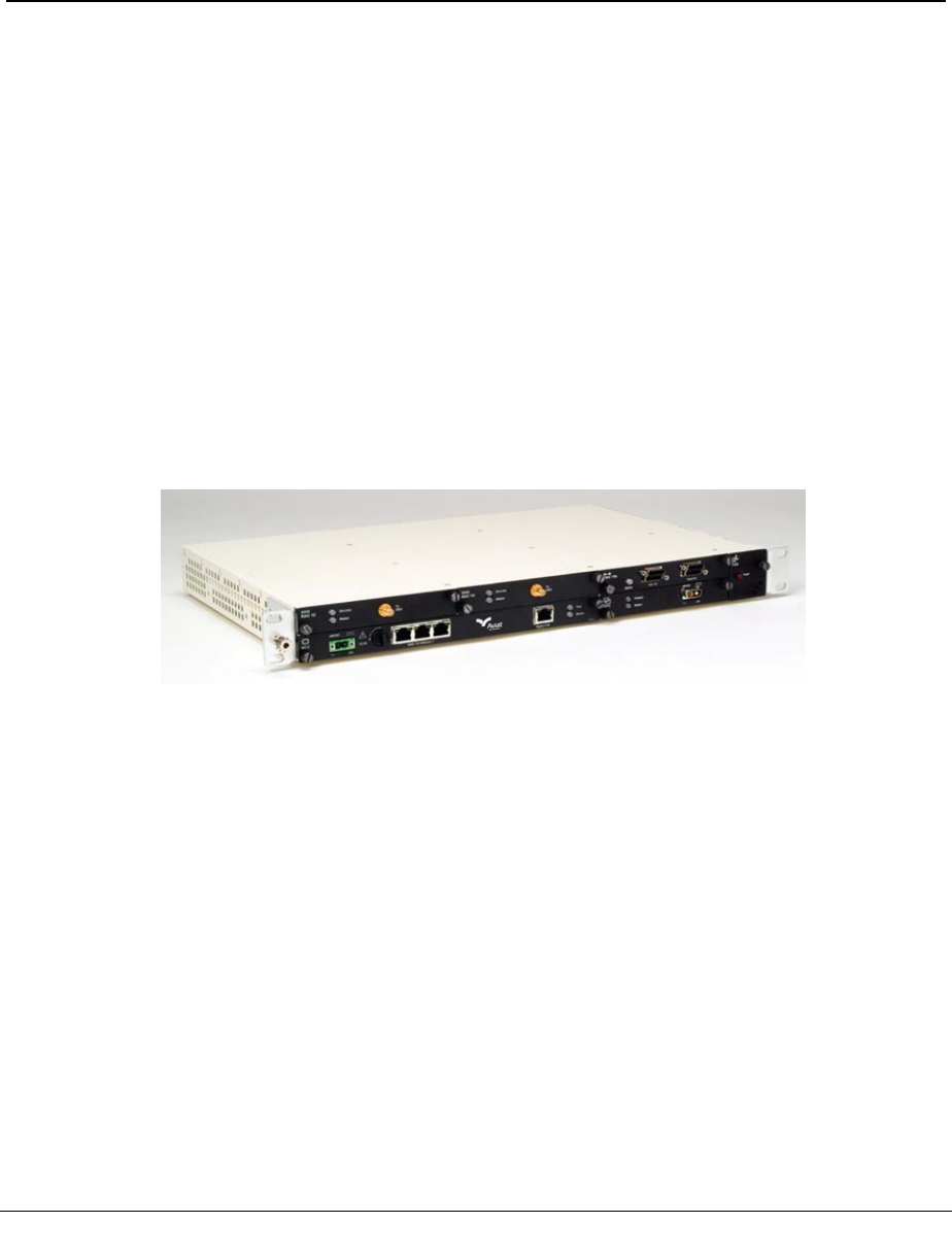
INU
The INU requires one NCC and one FAN, and has provision for four option plug-ins.
It supports a maximum of three ODUs for three non-protected links, or one pro-
tected/diversity link and one non-protected link.
Figure 1-2. INU
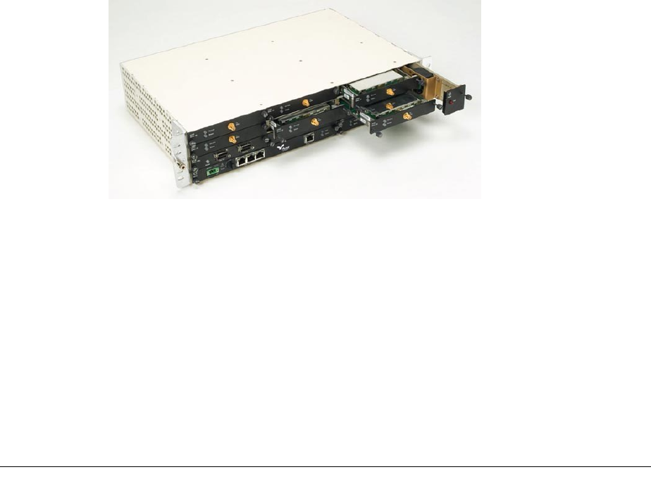
INUe
The INUe (INU extended) requires one NCC and one 2RU FAN, and has provision for
ten option cards. It supports a maximum of six ODUs for six non-protected links, or
up to three protected/diversity links.
260-668066-004 AUGUST 2013 17

VOLUME II, CHAPTER 1, SYSTEM OVERVIEW
Figure 1-3. INUe
See:
lPlug-in Cards on page 18
lData Packet Plane on page 24
lAdaptive Coding and Modulation (ACM) on page 24
lPlatforms on page 26
Plug-in Cards
Plug-in cards for the INU or INUe enable quick and easy customization on Eclipse
configurations. All cards are hot-pluggable.
RACs support the radio modem function. In the transmit direction they take the
digital traffic from the backplane or data packet plane and convert it to an IF signal
for connection to an ODU 600. The reverse occurs in the receive direction.
lOne RAC/ODU 600 combination is used for a 1+0 link.
lTwo RACs with two ODUs are used for 1+1 hot-standby or diversity links.
lRACs control TX switching and RX voting on protected / diversity links.
DACs support the user interface.
lDifferent DACs support Ethernet, DS1, DS3, and OC3 connections.
lMultiplexer DACs support transport of OC3 or DS3 with NxDS1 rates.
lEthernet DACs support a L2 switch function. DAC GE3 supports advanced
options for Synchronous Ethernet, ring/mesh protection, QoS, buffer
management, link aggregation, VLAN tagging, and OAM.
lMost DACs can be protected using a stacked (paired) configuration.
lDS1, DS3, and OC3 DACs support Ethernet-over-TDM options to enable
Ethernet transport over legacy TDM radio or leased-line links.
AUX (Auxiliary card) supports async or sync service-channel connections, and
alarm I/O options for connection to external devices.
18 AVIAT NETWORKS
ECLIPSE INSTALLATION MANUAL
NCC (Node Controller Card) provides Node management and DC-DC converter func-
tions. NCC is a mandatory card.
lIt manages Node operation and event collection and management.
lIt incorporates a router function for local and remote network management
interconnection.
lNode configuration and licensing data is held in flash-memory.
lPower supply: -48 Vdc (SELV -40.5 to -60 Vdc).
FAN (Fan card) provides forced-air cooling. FAN is a mandatory card.
NPC (Node Protection Card) provides 1+1 protection functions for the NCC power
supply and backplane management.
PCC (Power Conversion Card) supports operation from a +24 Vdc power supply.
Plug-in Cards Overview
For detail ed inf ormation on the pl ug-ins refer to the
Eclipse Pl atf orm Product Description.
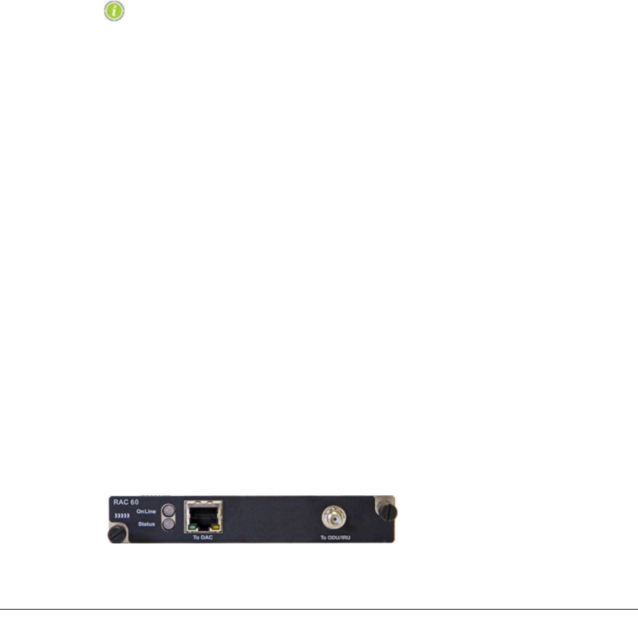
RAC 60E
RAC 60E supports DPP (Data Packet Plane) operation, ACM (Adaptive Coding and
Modulation), and airlink recovered timing (ART) for high accuracy radio transport of
a SyncE clock.
There are four dynamically switched modulation rates; QPSK, 16 QAM, 64 QAM,
256 QAM. Coding options additionally apply on each of these modulations, one for
maximum throughput, one for maximum gain, to provide an effective total of eight
modulation states.
lMaximum throughput delivers maximum data throughput - at the expense of
some system gain.
lMaximum gain delivers best system gain - at the expense of some throughput.
lUp to four of the eight modulation states offered with ACM can be selected for
use.
lModulation switching (state change) is errorless for priority traffic.
A DPP port enables direct routing of Ethernet traffic to a DAC GE3.
Individual ACM modulations can be set as fixed rates.
Channel bandwidths for ISM band operation range from 5 to 40 MHz.
ART operation is designed to meet G.8262 synchronization mask requirements for
SyncE clock transport.
Figure 1-4. RAC 60E
260-668066-004 AUGUST 2013 19

VOLUME II, CHAPTER 1, SYSTEM OVERVIEW
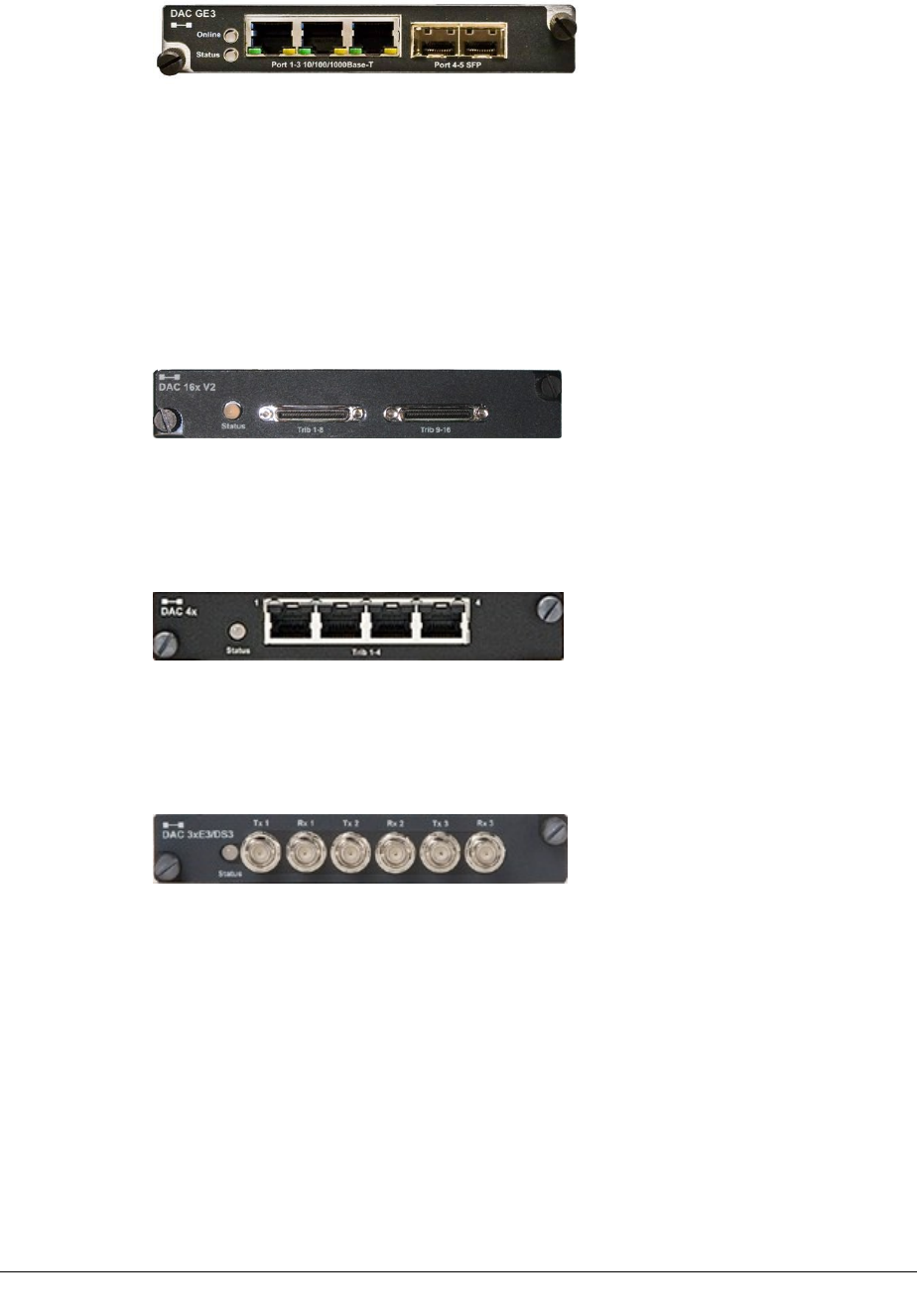
DAC GE3
DAC GE3 capabilities include Synchronous Ethernet, link aggregation, policing,
ring/mesh protection and Ethernet service OAM.
lThree RJ-45 10/100/1000Base-T ports
lTwo multi-purpose SFP ports with plug-ins for:
oOptical LC, 1000Base-LX, 1310 nm single-mode
oOptical LC, 1000Base-SX, 850 nm multi-mode
oElectrical RJ-45 10/100/1000Base-T
lSix transport channel (TC) ports
lComprehensive QoS traffic prioritization and scheduling options:
o802.1p mapping
oDiffServ mapping (IPv4, IPv6)
oMPLS Exp bits mapping
oStrict priority scheduling
oDeficit Weighted-Round-Robin (DWRR) scheduling
oHybrid strict + DWRR scheduling
oEight transmission queues
lTraffic policing using TrTCM (two rate, three color metering) with remarking
options
lL2 LAG (IEEE 802.1AX), static and LACP
lL1LA (Layer 1 link aggregation)
lAdvanced options for VLAN tagging, including Q (802.1Q), QinQ (802.1ad),
Filtering, Translation
lSynchronous Ethernet with Stratum 3 hold-over performance on timing
subsystem
lRSTP (IEEE 802.1w)
lERP (ITU-T 8032v2)
lEthernet service OAM (IEEE 802.1ag/IYU-T Y.1731: ETH-CC, ETH-LB, ETH-
LT)
lData packet plane (DPP) and/or backplane traffic interconnection to RACs
lAdvanced traffic shaping for fixed and adaptive modulation links
lSuperior burst management with 1500 Kbytes shared memory across active
ports
lStorm control
lJumbo frames to 10 Kbytes bi-directional
lFlow control (IEEE 802.3x)
l1+1 port and card protection
lInter-frame gap (IFG) and preamble stripping and re-insertion
lRMON stats per port, channel, and queue
20 AVIAT NETWORKS
ECLIPSE INSTALLATION MANUAL
Figure 1-5. DAC GE3
DAC 16xV2
DAC 16xV2 supports 16xDS1 tributaries on compact HDR connectors.
Features additional to those provided by DAC 16x include:
lTributary protection
lEthernet over DS1 tribs
lIndividual line code selection for AMI or B8ZS on DS1 tribs
Figure 1-6. DAC 16xV2
DAC 4X
DAC 4x supports 4xDS1 tributaries on individual RJ-45 connectors.
Figure 1-7. DAC 4X
DAC 3xDS3
DAC 3xDS3 supports 3xDS3 tributaries on paired mini-BNC connectors.
Figure 1-8. DAC 3xE3/DS3
DAC 3xDS3M
DAC 3xDS3M supports operational modes of:
lNormal DS3 tributary operation (as for DAC 3xDS3)
lM13 multiplexer mode. One or two DS3 interfaces are multiplexed to an NxDS1
backplane.
lDS3 Ethernet mode to enable up to 43 Mbit/s Ethernet over legacy TDM radio
or leased-line links (links must support transparent DS3).
Tribs are supported on paired mini-BNC connectors.
260-668066-004 AUGUST 2013 21
VOLUME II, CHAPTER 1, SYSTEM OVERVIEW
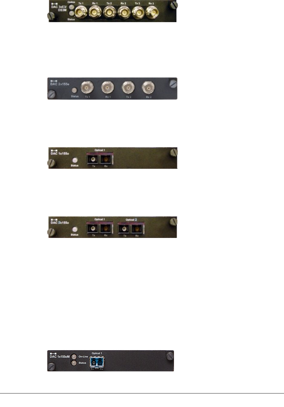
Figure 1-9. DAC 3xE3/DS3M
DAC 2x155e
DAC 2x155e supports two OC3 electrical (STS3) tributaries on paired BNC con-
nectors.
Figure 1-10. DAC 2x155e
DAC 1x155o
DAC 1x155o supports one OC3 single-mode optical tributary on SC connectors.
Figure 1-11. DAC 1x155o
DAC 2x155o
DAC 2x155o supports two OC3 single-mode optical tributaries on SC connectors.
Figure 1-12. DAC 2x155o
DAC 155oM
DAC 155oM multiplexes an OC3 optical tributary to an NxDS1 backplane. The user
interface is provided on an SFP optical transceiver. Different SFPs support 1310nm
single-mode, or 850nm multi-mode.
It functions as a terminal multiplexer; it terminates or originates the OC3 frame. It
does not support interconnection of ADMs as there is no provision to transport OC3
overheads for ADM to ADM synchronization.
In virtual tributary mode it transports up to 130 Mbit/s Ethernet over an OC3 link.
Options are provided for external/recovered, or internal clock sourcing.
Figure 1-13. DAC 155oM
22 AVIAT NETWORKS
ECLIPSE INSTALLATION MANUAL
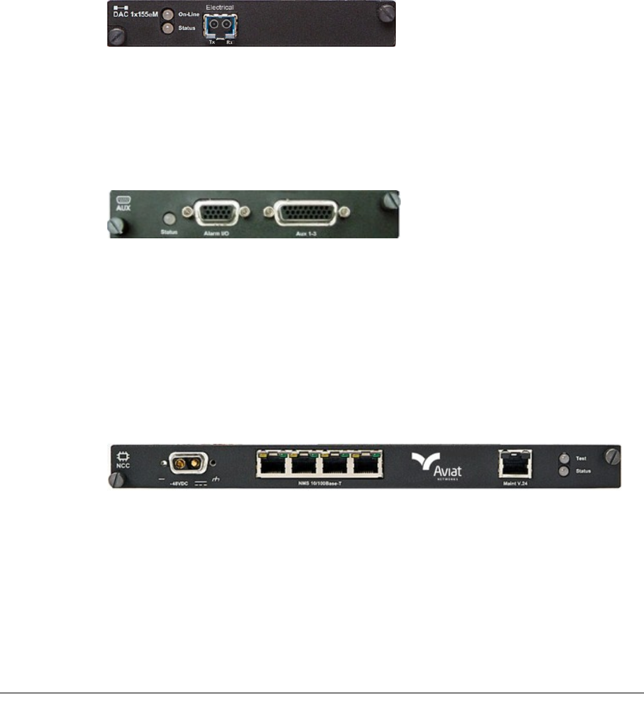
DAC 155eM
DAC 155eM multiplexes an OC3 electrical tributary to an NxDS1 backplane. The user
interface is provided on an SFP electrical transceiver.
It functions as a terminal multiplexer; it terminates or originates the OC3 frame. It
does not support interconnection of ADMs as there is no provision to transport OC3
overheads for ADM to ADM synchronization.
In virtual tributary mode it transports up to 130 Mbit/s Ethernet over an OC3 link.
Options are provided for external/recovered, or internal clock sourcing.
Figure 1-14. DAC 155oM
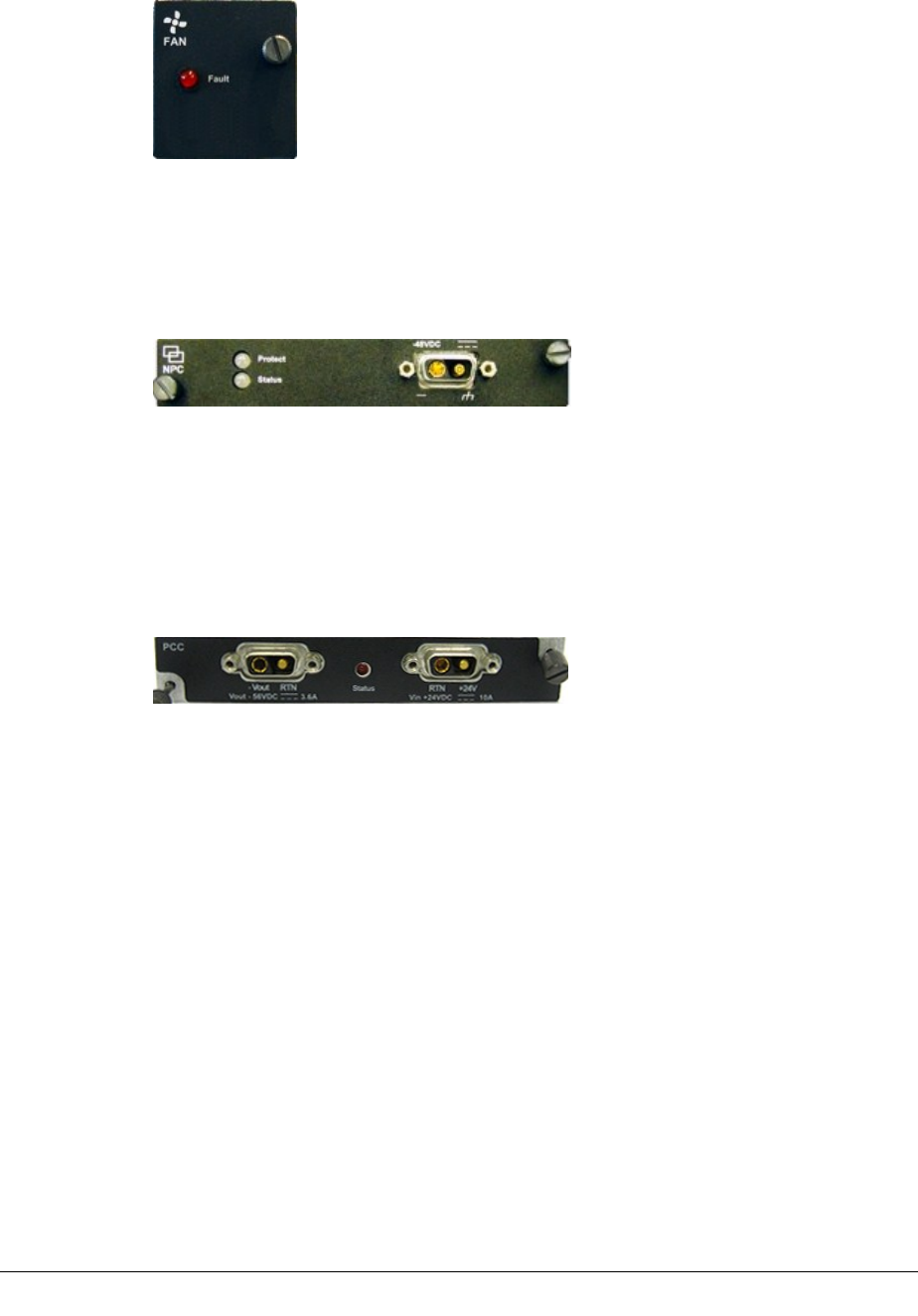
AUX
AUX provides synchronous and/or asynchronous auxiliary data channels, NMS port-
ing, and alarm input and output functions. Data options are sync at 64 kbps or
async to 19.2 kbps.
Figure 1-15.
NCC
The NCC is a mandatory plug-in for an INU/INUe. It performs key node man-
agement and control functions, and provides various dc rails from the -48 Vdc
input. It also incorporates a plug-in flash card, which holds Node configuration and
license data.
Power input limits are -40.5 to -60 Vdc. The power connector is a D-Sub M/F 2W2.
The +ve dc return pin is connected to chassis ground.
Figure 1-16. NCC
FAN
The FAN is a mandatory plug-in. There are two variants, 2RU and 1RU. Each is fit-
ted with two long-life axial fans plus monitoring and control circuits.
One 1RU FAN is fitted in an INU.
One 2RU FAN or two 1RU FANs are fitted in the INUe. The 2RU FAN is standard.
260-668066-004 AUGUST 2013 23
VOLUME II, CHAPTER 1, SYSTEM OVERVIEW
Figure 1-17. FAN (1RU)
NPC
NPC provides redundancy for the NCC backplane bus management and power sup-
ply functions.
Figure 1-18. NPC
PCC
The PCC provides a voltage conversion function for use at locations where the power
supply is +24 Vdc. It converts +24 (19 to 36) Vdc to -56 Vdc for connection to the
INU -48Vdc input. -56 Vdc represents the typical float voltage for a battery-backed -
48 Vdc supply.
Figure 1-19. PCC
Data Packet Plane
The high-performance data packet plane (DPP) operates independently of the back-
plane.
The DPP is enabled via direct cable connection between the front panel packet data
port on a RAC 60E, and a front-panel port on a DAC GE3. Customer traffic con-
nected to the DACs is bridged to the RACs, and then to the RF transceiver; the ODU
600.
Where required, customer data can also be sourced via the circuit-switched back-
plane, meaning both the DPP and backplane can be used to source/send traffic. This
has special relevance where native mixed-mode IP + TDM traffic is to be sent over an
Eclipse wireless link; GigE IP traffic via the DPP, and TDM traffic via the backplane.
Adaptive Coding and Modulation (ACM)
Advanced ACM options are provided using RAC 60E plug-in.
24 AVIAT NETWORKS

ECLIPSE INSTALLATION MANUAL
lAdaptive modulation maximizes use of available channel bandwidth.
lCoding provides options for maximum throughput or maximum system gain
on each modulation rate.
Adaptive Modulation (AM)
AM uses one of four automatically and dynamically switched modulations - QPSK,
16 QAM, 64 QAM, or 256 QAM. For a given RF channel bandwidth a two-fold
improvement in data throughput is provided for a change from QPSK to 16 QAM, a
three-fold improvement to 64 QAM, and a four-fold improvement to 256 QAM.
In many instances the link parameters that supported the original system gain can
be retained. For example, the antenna sizes and Tx power used for an original QPSK
link on a 7 MHz channel are unchanged when operated on 256 QAM using adaptive
modulation. The adaptive modulation engine ensures that the highest throughput is
always provided based on link quality.
Modulation switching is hitless/errorless. During a change to a lower modulation,
remaining higher priority traffic is not affected. Similarly, existing traffic is unaf-
fected during a change to a higher modulation.
Note that while adaptive modulation can also be used on PDH links and combined
PDH and Ethernet links, unlike Ethernet there is no QoS synergy on PDH con-
nections.
Ethernet connections enjoy real synergy through the QoS awareness on the DAC GE3
GigE switch, and the service provisioning provided by any MPLS or PBB-TE network
overlay. All high priority traffic, such as voice and video, continues to get through
when path conditions are poor. Outside these conditions 'best effort' lower priority
traffic, such as email and file transfers enjoy data bandwidths that can be up to four
times the guaranteed bandwidth.
DS1 connections by comparison are dropped in user-specified order when link capa-
city is reduced, and restored when capacity is increased.
Coding
Modulation code options provide two sets of modulation states, one for maximum
throughput, the other for maximum gain. These apply on each of the modulation
rates (QPSK, 16 QAM, 64 QAM, 256 QAM) to provide a total of eight modulation
states.
Maximum throughput delivers maximum data throughput - at the expense of some
system gain.
Maximum gain delivers best system gain - at the expense of some throughput.
Up to four of the eight modulation states offered with ACM can be selected for use.
For example:
lWith four modulation rates, each can be set for maximum throughput or
maximum gain.
260-668066-004 AUGUST 2013 25
VOLUME II, CHAPTER 1, SYSTEM OVERVIEW
lWith three modulation rates, such as 16 QAM, 64 QAM, 256 QAM, one rate
(any) can be set for maximum gain and additionally for maximum
throughput, to provide four step AM operation.
lWith two modulation rates, such as 16 QAM (or 64 QAM) with 256 QAM,
each can be set for maximum gain and additionally for maximum throughput,
to provide four step AM operation.
This feature provides a practical trade-off between capacity and system gain to fine-
tune link performance. It provides best balance on AM operation.
The four modulation rates support near-linear 2x, 3x, 4x capacity steps.
The coding options allow capacity/gain variations on these rates to always support
up to four steps, even when just two of the possible four modulation rates are in use,
or are permitted.
Even where just one modulation rate is required/permitted, the coding option sup-
ports two-step AM operation, one for maximum throughput, one for maximum gain.
Platforms
Eclipse supports flexible customization of traffic type, traffic capacity, and traffic pro-
tection for up to three links using the INU, and to six links using the INUe.
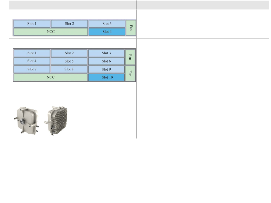
Platform Layout
Platform
INU Supports 3 non-protected links or 1 pro-
tected/diversity and 1 non-protected link.
1RU.
INUe Supports up to 6 non-protected links for:
1 protected/diversity and 4 non-protected links,
or
2 protected/diversity and 2 non-protected links,
or
3 protected/diversity links.
2RU.
ODU 600 QPSK to 256 QAM, 5.8 GHz ISM band (USA and
Canada).
Requires RAC 60E. Fixed or adaptive modulation
rates.
26 AVIAT NETWORKS
ECLIPSE INSTALLATION MANUAL
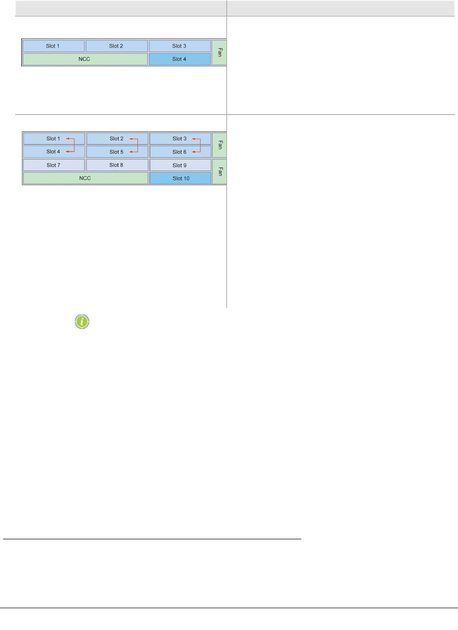
Slot Assignments
Slots
INU - Slots 1, 2, 3, 4 are universal: any RAC, DAC, or
AUX plug-in
- Slot 4 is NPC or universal: NPC or any RAC, DAC,
AUX
- NCC and FAN slots are dedicated
- For protected operation the RAC/RAC, RAC/DAC
155oM, or DAC/DAC pairings can be installed in
any of the universal slots
INUe - Slots 1, 2, 3, 4, 5, 6 are universal: any RAC,
DAC, or AUX plug-in
- Slots 7, 8, 9 are restricted: any DAC, or AUX,
except DAC 155oM/eM and AUX where NMS
access is required1
- Slot 10 is restricted: NPC option only
- NCC and FAN slots are dedicated - the INUe is
supplied standard with a single 2RU FAN,
though accepts two 1RU FANs
- RAC/RAC, or RAC/DAC 155oM/eM protected pair-
ings must be installed in the positions indicated
by the arrows
- For protected DACs, the protection partners can
be installed in slots 1 to 9, except for the DAC
155oM/eM where NMS access is needed, in
which case install only in slots 1 to 6
Data is transported natively over an Eclipse wireless li nk,
whether Ethernet or TDM.
1Internal (backplane bus) NMS access is only provided on slots 1 to 6. Do not install DAC
155oM, DAC 155eM, or AUX in slots 7 to 9 if an NMS connection is required in their con-
figuration.
260-668066-004 AUGUST 2013 27

VOLUME II, CHAPTER 1, SYSTEM OVERVIEW
ODU 600 for 5.8 GHz ISM Band
ODU 600 supports fixed modulation or adaptive modulation (with RAC 60E).
lLicense-based upgrades enable transition from Tx standard power to high
power Flexible Power Mode (FPM).
lODU 600 is supplied with diplexers for Tx high or Tx low working.
lODU 600 is designed for direct-antenna mounting, but can be remote
mounted using an ODU remote-mount kit.
lEqual-loss and unequal-loss direct-mounting couplers are available for hot-
standby or frequency diversity single antenna operation.
5.8 GHz Unlicensed Band
Eclipse INUs with ODU 600 are compliant with FCC CFR47, Part 15.247, and
Industry Canada RSS-210 Annex 8, on ISM frequency band 5725 to 5850 MHz. Inter-
national use is not supported; the system does not employ DFS and as such cannot
be deployed within Europe or any country where DFS is a regulatory requirement for
protection of radars.
Features and Capabilities:
lBandwidths 5, 10, 20, 30, or 40 MHz.
lAdaptive or fixed modulation options.
lSupports Ethernet and/or NxDS1 payloads, with air-link capacities to 254
Mbps (40 MHz Ch BW).
lHot-standby and diversity protection options.
lOutput power is limited to 28 dBm at the waveguide port to ensure
compliance with the FCC 1 Watt rule.
lFor Tx power and system gain figures, see the Eclipse ODU 600 datasheet.
Operational Limitations and Restrictions
Unlicensed band operation means sharing the air-space with other operators of unli-
censed band links. Interference is possible.
lODU 600 5.8 GHz operation is 'narrow-band'; it competes/shares spectrum
with other narrow-band links and with spread-spectrum links.
lPerformance could deteriorate over time with the introduction of other links in
the same geographical area.
lAntennas must be approved (FCC or Industry Canada) for 5.8 GHz unlicensed
band.
28 AVIAT NETWORKS

ECLIPSE INSTALLATION MANUAL
oODU 600 at 5.8 GHz is certified for use with a parabolic antenna with a
maximum gain of 45.9 dBi.
260-668066-004 AUGUST 2013 29

VOLUME II, CHAPTER 1, SYSTEM OVERVIEW
Protection Options
Eclipse supports link, interface, network, and platform protection options:
Link/Path Protection
Hot-standby, space diversity, or frequency diversity options are supported.
Rx voting is hitless/errorless; Tx switching is not hitless. The maximum restoration
time for a Tx switch is 200 ms.
A remote Tx switch is forced in the event of a silent Tx failure.
Interface Protection
DS1, DS3 and OC3 interfaces can be hot-standby protected using paired (stacked)
DACs.
The protectable DACs are DAC 16x V2, DAC 3xDS3, DAC 3xDS3M, DAC 2x155o,
DAC 2x155e, DAC 155oM.
When a switch occurs, all Tx and/or Rx tributaries are switched to the protection
partner.
Two protection configurations are supported, tributary protection, and always-on:
Tributary Protection
lY cables connect the paired DACs to customer equipment.
lIn the Rx direction (from the customer) both DACs receive data, but only the
online
Rx DAC sends this data to the TDM bus.
lIn the Tx direction, the online Tx DAC sends data to customer equipment, the
other mutes its Tx line interface.
Tributary Always-On
lSeparate cables connect each DAC to customer equipment.
lIn the Rx direction (from the customer) both DACs receive data, but only the
online Rx DAC sends this data to the TDM bus.
lIn the transmit direction both DACs send data to customer equipment, and
the customer equipment switches between these two always-on tributaries.
Protection switching is not hitless. The maximum restoration time for a Tx or Rx trib
switch is 200 ms. Typical restoration times are between 80 ms and 120 ms.
30 AVIAT NETWORKS

ECLIPSE INSTALLATION MANUAL
Network/Data Protection
lEthernet ring network protection is supported on DAC GE3 using ERP (ITU-T
8032v2 Ethernet Ring Protection) or RSTP (IEEE 802.1w).
lEthernet data redundancy is supported on L1 and L2 link-aggregated links
(DAC GE3).
lPDH ring protection is supported by an DS1 loopswitch capability, or a ring-
wrap Super PDH (SPDH) option.
Ethernet Ring and Mesh Networks
ERP uses standard Ethernet bridging and OAM protocols and OAM automatic pro-
tection switching (APS) messaging to provide a fast-acting protection mechanism for
ring networks.
RSTP uses a development of the spanning tree protocol (STP) to prevent network
loops and provide path redundancy.
Ethernet Link Aggregation (N+0 Protection)
Traffic redundancy is supported on co-path Ethernet links using L1 or L2 link aggreg-
ation. If one link fails its traffic is recovered on the remaining link or links. While the
reduced bandwidth may result in some traffic loss for low-priority traffic, appro-
priate QoS settings should ensure security for all higher priority traffic.
PDH Ring Protection
Eclipse supports two DS1 ring protection mechanisms, loop-switch and SPDH.
lThe loop-switch function configures a bi-directional redundant ring with a
hitless switching capability. Rings can be configured using RACs, and
PDH/SDH mux DACs.
lSPDH uses a ring-wrap mechanism formed on east/west facing RAC/RAC or
RAC/DAC 155oM combinations. Switching is not hitless.
Platform Protection
Platform management functions provided by the NCC are protected using the NPC
option to protect essential Backplane Bus and power supply functions.
Bus Protection
lProtects all circuit/tributary traffic. Alarm I/O is not protected.
lSwitching is not hitless for an NCC bus clock failure; restoration is within 200
ms, during which time all traffic on the NTU is affected.
lWhen the bus clock has switched to NPC control, it will not automatically
revert to NCC control on restoration of the NCC. Return to NCC control
requires either withdrawal/failure of the NPC, or use of diagnostic commands.
260-668066-004 AUGUST 2013 31

VOLUME II, CHAPTER 1, SYSTEM OVERVIEW
Power Supply Protection
lProtection is hitless for an NCC power supply failure. If the NCC converter or
one of its supply rails fails, the NPC will take over without interruption. And
vice versa.
lWith an NPC installed, the NCC can be withdrawn and replaced without
further impacting traffic.
lFor 24 Vdc operation two PCCs are required for platform protection, one each
for the NCC and NPC.
32 AVIAT NETWORKS

ECLIPSE INSTALLATION MANUAL
Licensing
Eclipse is subject to capacity and feature licensing.
Capacity Licensing
Capacity licensing is INU and INUe based (node-based). A single license applies
across all installed RACs installed in an INU/INUe.
lLicensed capacity ranges from 50 Mbps with license EZE-08001, to 2 Gbps
with license EZE-08010
lCapacity license is auto-allocated or user-allocated between installed RACs.
lUpgrade licenses are available to increase existing capacity supported on a
node.
Node Feature Licensing
Feature licenses provide access to extended Eclipse functionality.
lA feature license is a node-based license - it applies across all relevant cards
installed in the node.
lWhen a feature is required on a new node it is ordered together with the
capacity license for the node.
lFeature licenses can be separately ordered as upgrades on existing nodes.
Node Feature Overview
Feature Licenses:
EZF-01: Layer 1 Link Aggregation (DAC GE3)
L1 link aggregation (L1LA) splits traffic between links on a byte-segment basis.
It supports higher burst capacities compared to L2 link aggregation - throughput
can burst to the aggregated total capacity, unlike L2 link aggregation.
L1LA (like L2 link aggregation) supports redundancy - data from a failed link is dir-
ected onto the remaining link, or links.
L1LA on DAC GE3 is modulation-aware; load re-balancing occurs on modulation
change under adaptive modulation.
EZF-02: Adaptive Modulation (RAC 60E)
Modulation is automatically and dynamically switched between modulation selec-
tions.
260-668066-004 AUGUST 2013 33

VOLUME II, CHAPTER 1, SYSTEM OVERVIEW
EZF-03: Secure Management (NMS)
Secure Management applies to Eclipse NMS access over the network, and to local
access via the Portal craft tool.
lProvides secure management access to Eclipse over an unsecured network.
lProtects Eclipse configurations from accidental or intentional modification by
unauthorized personnel.
lKeeps track of all events for accountability.
lBased on FIPS 140-2 validated algorithms.
EZF-04: Payload Encryption (RAC 60E)
Payload Encryption encrypts payload and management data on the wireless link to
prevent eavesdropping.
lChecks integrity of each data frame in the wireless link to ensure that received
data has been sent by the intended transmitter.
lProvides the same level of security as Wi-Fi and WiMAX.
lFIPS-197 compliant.
lCan be enabled/disabled independently for each wireless link.
lMeets US federal and commercial requirements.
EZF-05: Ethernet over TDM (DS3, DS1)
Enables mapping of Ethernet data to DS3, DS1 PDH interfaces using the DAC
3xDS3M or DAC 16xV2. Applies where a customer wishes to transport Ethernet data
over existing DS3 or NxDS1 radio or leased-line circuits.
lEthernet data from the Eclipse backplane is mapped into a DS3 frame as DS1
(1.544 Mbps) multiples to a maximum 28xDS1, to support a maximum data
rate (available bandwidth for Ethernet) of 43 (43.232) Mbps per DS3. The DS3
connection must support unframed/transparent DS3.
lEthernet data is mapped into NxDS1 frames at 1.544 Mbps per DS1 to a
maximum 16xDS1 on the DAC 16xV2, to support a maximum data rate
(available bandwidth for Ethernet) of 24 (24.7) Mbps.
EZF-06: RADIUS Client
Enables connection validation to a RADIUS server for centralized account man-
agement.
EZF-09: Synchronous Ethernet
Enables Synchronous Ethernet operation on DAC GE3 cards.
EZF-10: Ethernet OAM/ERP
Enables access to DAC GE3 Ethernet OAM and ERP capabilities.
EZF-51 to EZF-56: ODU 600 High Tx Power.
Unlocks an additional 3dB of transmit power over standard power. Applies, on all
modulations. It also increases the manual and ATPC transmit power control range
by 3dB.
34 AVIAT NETWORKS

ECLIPSE INSTALLATION MANUAL
lEZF-51: ODU 600 High power option 1 x ODU
lEZF-52: ODU 600 Nodal High power option 2 x ODU
lEZF-53: ODU 600 Nodal High power option 3 x ODU
lEZF-54: ODU 600 Nodal High power option 4 x ODU
lEZF-55: ODU 600 Nodal High power option 5 x ODU
lEZF-56: ODU 600 Nodal High power option 6 x ODU
260-668066-004 AUGUST 2013 35

VOLUME II, CHAPTER 1, SYSTEM OVERVIEW
Configuration and Management
Eclipse is a software-driven product; there are no manual controls. Configuration
and management is achieved via Portal and ProVision.
Portal is a PC based configuration and diagnostics tool for Eclipse.
ProVision is the Eclipse network element manager. ProVision also supports other
Aviat Networks products, including legacy products.
Portal is supported in the Eclipse system software, such that once installed on a
PC, it automatically downloads support from the radio as needed to ensure Portal
always matches the version of system software supplied, or subsequently down-
loaded in any radio upgrade.
Portal has the look and feel of a Windows environment with screen-based views and
prompts for all configuration and diagnostic attributes.
A Portal PC connects to an INU/INUe using Ethernet or V.24 options.
For more information refer to the Eclipse Configuration Guide.
ProVision is the network element manager for all Aviat Networks radios (current
and legacy). ProVision also supports partner products, including multiplexors,
switches, routers, and power systems.
ProVision is installed on a Windows or Solaris server, typically at a network oper-
ating center, and communicates with network elements using standard LAN/WAN
IP addressing and routing; each radio has its own unique IP address.
For more information, refer to the Aviat Networks ProVision User Guide.
Secure Access from Portal and ProVision is enabled through the Secure Management
and RADIUS Client strong security options.
36 AVIAT NETWORKS

ECLIPSE INSTALLATION MANUAL
Antennas
Parabolic antennas for the 5.8 GHz unlicensed band must be FCC approved have a
maximum gain not exceeding 45.9 dBi.
For information on approved antenna types and availability, contact Aviat Networks
or your supplier.
The antenna mounts used are designed for installation on industry-standard 115
mm OD (4.5 inch) pipe-mounts.
For information on installing and aligning antennas, refer to the data supplied with
the antennas.
260-668066-004 AUGUST 2013 37

VOLUME II, CHAPTER 1, SYSTEM OVERVIEW
Power Supply
Eclipse is designed to operate from a -48Vdc power supply (+ve earth) but will oper-
ate to specification over a voltage range of -40.5 to -60Vdc.
A plug-in PCC option provides a voltage conversion function for locations where the
power supply is +24 Vdc. It converts +24 (19 to 36) Vdc to -56 Vdc for connection to
the INU -48Vdc input. -56 Vdc represents the typical float voltage for a battery-
backed -48 Vdc supply.
One PCC supports a maximum three ODUs, plus any combination of RACs and
DACs.
The dc power supply must be UL or IEC compliant for SELV (Safety Extra Low
Voltage) output (60Vdc maximum limited).
38 AVIAT NETWORKS

ECLIPSE INSTALLATION MANUAL
Volume III: Installation
260-668066-004 AUGUST 2013 39

VOLUME III, CHAPTER 1, INSTALLATION
40 AVIAT NETWORKS

ECLIPSE INSTALLATION MANUAL
Chapter 1. Introduction to
Installation
This section provides a list of recommended installation tools and materials, and a
procedure for unpacking and checking the equipment.
Eclipse has been tested for and meets EMC Di r ective
89/336/EEC. The equipment was tested using screened cable;
if any other type of cable is used, it may violate compliance.
CAUTION:Eclipse is a Class A product. In a domestic environment it
may cause radio interference: be prepared to resolve this. Eclipse
equipment is intended to be used exclusively in telecommunications
centers.
WARNING: You must comply wi th the relevant health
and safety practices when wor king on or around
Eclipse r adio equi pment. Refer to Health and Safety on
page 5
Installation Overview
The following list provides a basic guide, in order, of an Eclipse hardware install-
ation process.
Hardware installation typically proceeds as follows:
1. Pre-Installation
lUnpack equipment - see Unpacking on page 42
lVerify system configuration
lCheck basic components
lCheck kits and accessories
2. Installation
lAntenna - refer to the antenna manufacturer's installation instructions
lODU 600 - see ODU Installation on page 43
lINU chassis - see INU and INUe Installation on page 71
lINU plug-in cards - see Plug-in Installation on page 83
lTraffic and NMS cables - as required
For mor e information on i nstal l ati on practi ce refer to the
Aviat Networks' publication 'Best Practices Guide'.
260-668066-004 AUGUST 2013 41

VOLUME III, CHAPTER 1, INTRODUCTION TO INSTALLATION
Installation Tools and Materials
Ensure you have the following tools and material before going to site. These are
items to be sourced/supplied by the installer.
The items are indicative for standard installations. For non-standard installations
additional materials and tools may be required.
Table 1-1. Required Tools and Material
Equipment Tool/Material Description
Antenna As required by the
manufacturer/supplier
Refer to the manufacturer’s data supplied with each antenna
for required and recommended installation tools and
equipment. (Aviat Networks offers antennas from several
suppliers).
Eclipse Radios Basic electrician’s toolkit The kit must include a crimp lugs, a crimp tool for attaching the
lugs to stranded copper cable, a multimeter.
Torque wrench Capable of 66 N-m or 50 ft-lb, with a selection of sockets for
antenna mount fastening
Hot-air gun For use on the heat-shrink tubing.
Protective grease and
zinc-rich paint
For weather-protecting grounding attachment points on towers
and grounding bars.
4mm2(#12) green PVC
insulated strand copper
wire and grounding lugs
For grounding the indoor unit to the rack/frame
16 mm2(#6) green PVC
insulated strand copper
wire and grounding lugs
For grounding the rack to the station ground.
Unpacking
To unpack Eclipse equipment:
lOpen the shipping boxes, carefully remove the equipment and place it on a
clean, flat working surface.
lEnsure all the basic components and accessories for your system have been
included in the shipment by comparing the packaging, component part
numbers and product descriptions against the packing list, and cross-checking
against the installation datapack for the system to be installed.
lIf there has been shipping damage or there are discrepancies between the
equipment expected and the equipment received, contact an Aviat Networks
Help Desk or your supplier.
42 AVIAT NETWORKS

ECLIPSE INSTALLATION MANUAL
Chapter 2. ODU Installation
This section describes installation procedures for ODU 600 and associated antennas,
couplers and cables. Refer to:
lInstalling the Antenna on page 44
lInstalling a Coupler on page 45
lInstalling the ODU on page 49
lInstalling ODU Cables and Connectors on page 58
lInstalling Lightning Surge Arrestors on page 63
lWeatherproofing on page 69
260-668066-004 AUGUST 2013 43

VOLUME III, CHAPTER 2, ODU INSTALLATION
Installing the Antenna
Before going to the antenna installation site, check that you have the required install-
ation tools as recommended by the antenna manufacturer.
Also make sure you have the data needed to locate the antenna on the tower, and to
set its polarization and initial pointing.
lThe parabolic antennas available from Aviat Networks for the 5.8 GHz
unlicensed band are FCC approved and have a maximum gain not exceeding
45.9 dBi.
lThey include a collar for direct-mounting the ODU.
lThe collar includes a polarization rotator.
lThe antenna mount is designed for installation on industry-standard 115 mm
OD (4.5 inch) pipe-mounts.
lAll antennas are supplied with an installation guide.
lFor information more information contact Aviat Networks or your supplier.
Refer to the Aviat Networks Best Practices Guide for supporting data.
44 AVIAT NETWORKS

ECLIPSE INSTALLATION MANUAL
Installing a Coupler
Refer to:
lCoupler Overview on page 45
lCoupler Installation Procedure on page 45
lUnused and Disconnected Coupler Ports on page 47
Coupler Overview
Couplers for protected hot-standby operation are available for equal loss or unequal
loss.
lFor equal loss the attenuation per side is nominally 3.5 dB (3.5 / 3.5 dB),
which applies to both the transmit and receive directions, meaning the
additional total one-way attenuation compared to a non-protected link is 7
dB.
lFor unequal loss the attenuation is nominally 1.5/6.5 dB.
When using a coupler to combine two ODUs onto a single polarization, the operating
channels must be chosen from within the same diplexer option. If the two ODUs are
not from the same tuning/diplexer option then interference may occur, resulting in
degraded link performance.
For informati on on unequal coupl er (combiner) rationale r efer
to the Best Practices Guide.
5.8 GHz coupler waveguide flanges have a UAR70 6 hole (IEC) pattern flange on the
ODU ports and UDR on the antenna-facing port.
Coupler Installation Procedure
A coupler installation guide is included wi th each coupl er.
The following procedure summarizes installation of a direct-mounted coupler. A
coupler may also be remote-mounted, with a single flexible waveguide used to con-
nect the coupler to its antenna.
Attaching a Direct-Mounted Coupler
Before installing a coupler check there will be sufficient mechanical clearance for the
coupler and its ODUs. There should be no clearance issues using Aviat Networks’
approved antennas when installed correctly on its mount with the appropriate left or
260-668066-004 AUGUST 2013 45

VOLUME III, CHAPTER 2, ODU INSTALLATION
right offset. However care must be taken at locations where a non-standard antenna
installation is required.
The ODUs are attached to the coupler as if attaching to an antenna except that there
is no polarization rotator associated with each ODU. Rather the coupler polarization
is set to match the V or H antenna polarization using 0 degree or 90 degree coupler
interfaces, which are supplied with the coupler. Couplers are default fitted with the
vertical polarization interface.
A coupler must always be installed onto its antenna before ODUs are attached to the
coupler.
The coupler type is the Aviat Networks OCU (ODU Coupler Unit), which is supplied
as a kitset for local assembly. The kitset includes assembly instructions.
Installation Procedure
For a vertically polarized antenna proceed to step 2. For a horizontally polarized
antenna begin at step 1. Polarization setting is described in Setting the Polarization
on page 50.
1. Assemble the coupler (OCU) according to the instructions provided.
2. Check the polarization required. Change/replace the interface in accordance
with the instructions provided.
3. Remove all protective tape from the waveguide ports and check that the
ODU/coupler mounting collar, polarization rotator, coupler interface and O-
ring, are undamaged, clean, and dry. Ensure the correct O-ring is fitted for
the OCU.
4. Apply a thin layer of silicon grease around the coupler interface O-ring. A
tube of silicon grease is included in ODU and coupler installation kits.
5. Fully loosen the nuts on the four coupler mounting bolts.
6. Position the coupler so the waveguide slots (coupler and rotator) will be
aligned when the ODU is rotated to its end position.
7. Fit the coupler onto its mounting collar by inserting the bolts through
receptor holes in the collar, then rotate the coupler clockwise to bring the
mounting bolts hard up against the slot ends.
8. Carefully bring the coupler forward to fully engage the coupler feed head
with the polarization rotator in the mounting collar.
9. Finger-tighten the four nuts, checking to ensure correct engagement of
coupler with mounting collar.
10. Ensure the coupler bolt-down points are correctly seated, then tighten the
four nuts with an open-ended 19mm (3/4”) spanner.
11. To remove a coupler, reverse this procedure.
Related procedures are:
Installing the ODUs; refer to Direct-Mount ODU Attachment Procedure on page 52.
Note that when attaching an ODU to a coupler there is no requirement to first set a
polarization; the ODUs are simply attached such that when rotated into position
there is correct alignment of the waveguide slots. When fitting the ODUs ensure cor-
rect cable exit - the ODU cable must exit facing down.
46 AVIAT NETWORKS
ECLIPSE INSTALLATION MANUAL
Installing the ODU Lightning Surge arrestor; refer to Installing Lightning Surge
Arrestors on page 63.
Grounding an ODU; refer to Grounding the ODU on page 56
Installing the ODU cable and connectors; refer to Installing ODU Cables and Con-
nectors on page 58
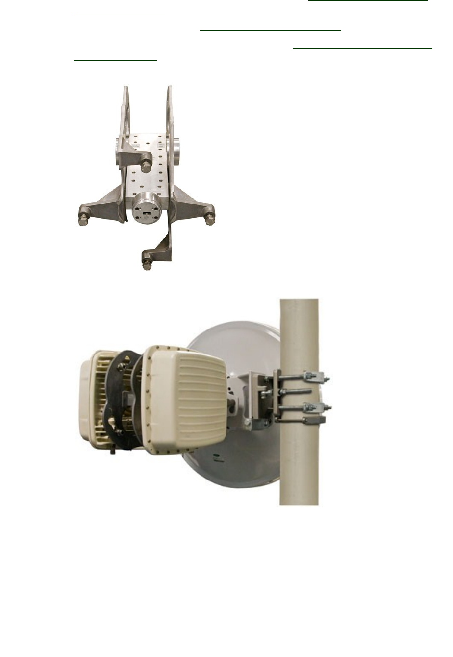
Figure 2-1. 'OCU' Back-to-Back Coupler
Figure 2-2. 'OCU' on Mount
Unused and Disconnected Coupler Ports
Unused ODU ports on a coupler must the blanked off with a microwave load as at
some frequencies the reflected power can affect operation at the remaining port,
260-668066-004 AUGUST 2013 47

VOLUME III, CHAPTER 2, ODU INSTALLATION
partly canceling the wanted signal.
A flange-mounted termination is used to absorb the RF energy. They are needed in
1+0 and cascaded coupler applications where some ODU ports are left open/not
attached to an ODU.
Terminations are available from Aviat Networks.
48 AVIAT NETWORKS

ECLIPSE INSTALLATION MANUAL
Installing the ODU
ODU 600 is designed for direct-mounting onto a collar supplied with Aviat direct-fit
5.8 GHz antennas. It can also be installed with standard 5.8 GHz antennas using a
flex-waveguide remote-mount kit.
For single-antenna protected operation a coupler is available to support direct
mounting of the two ODUs to its antenna. The coupler may also be remote mounted,
with a flex-waveguide connecting the coupler to its antenna.
Refer to:
lDirect-Mounted ODU Installation on page 49
lRemote-Mounted ODUs on page 53
lGrounding the ODU on page 56
Direct-Mounted ODU Installation
Refer to:
lOverview on page 49
lSetting the Polarization on page 50
lDirect-Mount ODU Attachment Procedure on page 52
ODU installation kits include:
lAn earth strap (2M) with lugs
lTube of silicon grease
lType-N angle adapter
Overview
ODU 600 attaches directly onto its antenna mount using four M10 SS bolts.
260-668066-004 AUGUST 2013 49
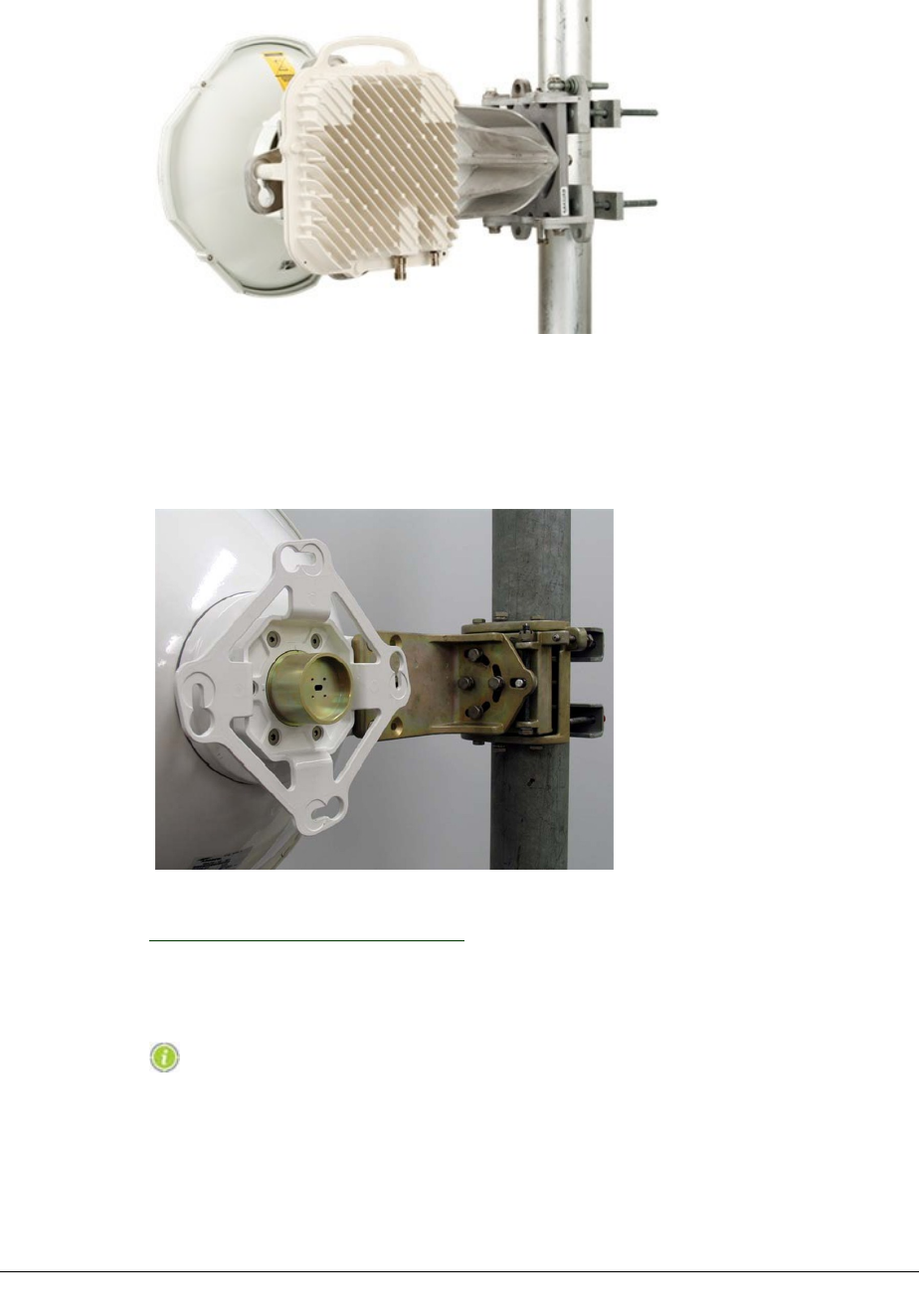
VOLUME III, CHAPTER 2, ODU INSTALLATION
Figure 2-3. ODU 600 on Antenna Mount
The figure below shows the ODU mounting collar, pole mount and polarization
rotator for an Andrew antenna. The orientation of the waveguide slot indicates ver-
tical polarization.
Figure 2-4. Andrew Pole Mount and ODU Mounting Collar
Next Step:
Setting the Polarization on page 50.
Setting the Polarization
Antenna installati on instructions are included with all anten-
nas. They include procedures for setti ng polarization.
The polarization of the transmitted signal, horizontal or vertical, is determined by
the antenna. The polarization (orientation) of the ODU is set to match its antenna
Direct-Mounted ODUs: For direct-mounted ODUs, antenna polarization is set
using a polarization rotator fitted within the ODU mounting collar.
50 AVIAT NETWORKS

ECLIPSE INSTALLATION MANUAL
lThe rotator is an integral part of the antenna mount. Vertical polarization is
the default setting.
lThe V and H settings are indicated on the rotator head.
Remote-Mounted ODUs are used where standard antennas are used (antennas
are not fitted with the Eclipse mounting collar).
lAntenna installation for V or H polarization is normally determined by the
orientation of the waveguide port / slot.
lTo remote mount an ODU, refer to Remote-Mounted ODUs on page 53.
lThis figure shows antenna waveguide port (slot) orientation for vertical and
horizontal polarization settings.
Figure 2-5. Antenna Waveguide Slot Orientation for V and H Polarization
ODU Rotator Procedure
If the ODU rotator is not set for the required polarization, you must adjust its ori-
entation. This topic describes typical adjustment procedures for Andrew antennas.
Similar procedures apply to other antennas approved by Aviat Networks. Instruc-
tions are included with all antennas.
To change the polarization of the Andrew antenna:
1. Release (do not completely undo) the six metric Allen-head screws approximately
10mm (3/8”). Pull the collar forward and hold the rotator back, which will allow the
rotator to disengage from a notch in the collar, and turn freely.
2. Turn the rotator hub 90° until it locates back into a notched “timing recess” in the
collar.
3. Check that the timing mark on the rotator hub has aligned with either a V or an H
on the collar to confirm polarization as shown below.
4. Ensure the rotator hub is correctly seated within its collar, then push the collar
back against the antenna mount and re-tighten the six screws.
260-668066-004 AUGUST 2013 51
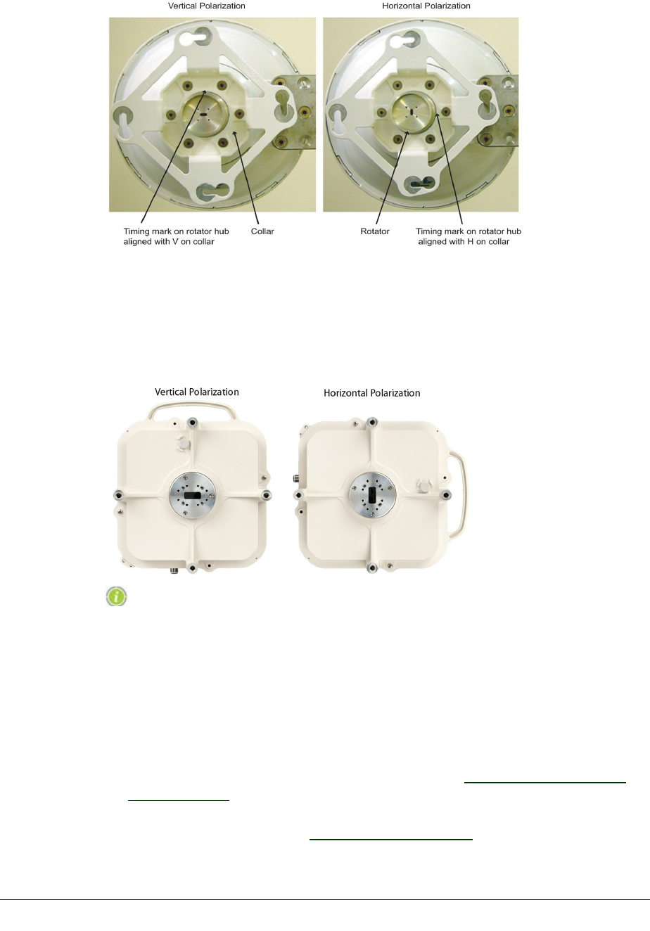
VOLUME III, CHAPTER 2, ODU INSTALLATION
Figure 2-6. Andrew ODU Collar and Polarization Rotator
ODU Polarization
The ODU must be mounted on the collar to match the chosen polarization. Correct
positioning for vertical or horizontal polarization is shown:
Figure 2-7. ODU 600 Orientation for Vertical and Horizontal Polarization
The ODU shoul d be mounted with Its connectors faci ng down.
Direct-Mount ODU Attachment Procedure
This topic describes the physical attachment of an ODU to an antenna mounting col-
lar.
Related procedures are:
lInstalling the ODU Lightning Surge arrestor; refer to See "Installing Lightning
Surge Arrestors". This is only required for ODUs not fitted with an internal
lightning surge arrestor.
lGrounding an ODU; refer to See "Grounding the ODU"
52 AVIAT NETWORKS

ECLIPSE INSTALLATION MANUAL
lInstalling the ODU cable and connectors; refer to See "Installing ODU Cables
and Connectors"
Attaching the ODU
An ODU should be installed with connectors facing down.
To attach the ODU:
1. Check that the ODU mounting collar, polarization rotator, ODU waveguide feed
head and O-ring, are undamaged, clean, and dry.
2. Set the polarization rotator for the required polarization. Refer to Setting the Polar-
ization on page 50.
3. Apply a thin layer of silicon grease around the ODU feed-head O-ring.
A tube of silicon gr ease is included in the ODU installation kit.
4. Screw each ODU mounting bolt in approximately six turns.
5. Position the ODU so the waveguide slots (ODU and rotator) will be aligned when
the ODU is rotated to its end position.
6. Fit the ODU onto its mounting collar by inserting the bolts through receptor holes
in the collar, then rotate the ODU clockwise to bring the mounting bolts hard up
against the slot ends.
7. Carefully bring the ODU forward onto the antenna to fully engage the ODU feed
head with the polarization rotator.
8. Finger-tighten the four bolts, checking to ensure correct engagement of ODU with
mounting collar.
9. Ensure the ODU bolt-down points are correctly seated, then firmly tighten the
four bolts with an open-ended 19mm (3/4”) spanner. If a torque wrench is used, set
for a value between 18-22 Nm.
10. To remove an ODU, reverse this procedure.
Remote-Mounted ODUs
Refer to:
lRemote-Mount Overview on page 53
lRemote-Mount Installation Procedure on page 55
lWaveguide Flange Data: ODUs on page 56
Remote-Mount Overview
The ODU 600 can be installed separate from its antenna, using a remote-mount to
support the ODU, and a flexible-waveguide to connect the ODU to its antenna:
The remote mount allows use of standard, single or dual polarization antennas.
260-668066-004 AUGUST 2013 53
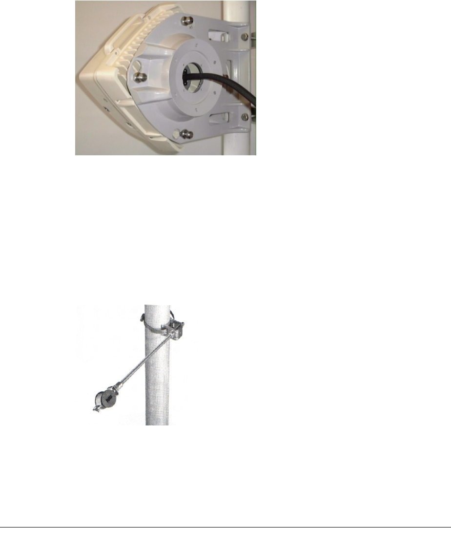
VOLUME III, CHAPTER 2, ODU INSTALLATION
The mount can also be used to remotely support a protected ODU pairing installed
on a coupler. The coupler connects to the remote mount assembly in the same way
as an ODU.
The remote mount clamps to a standard 112mm (4”) pole-mount, and is common to
all frequency bands. The figure below shows an ODU installed on a remote mount.
Two versions of the remote mount are available, a cast unit (as shown) and a stain-
less steel unit.
Figure 2-8. Remote Mount
Flexible waveguides are frequency band specific and are normally available in two
lengths, 600mm (2ft) or 900 mm (3ft). Both flange ends are identical, and are
grooved for a half-thickness gasket, which is supplied with the waveguide, along
with flange mounting bolts.
To prevent wind-flex, a flexible waveguide or coax must be suitably fastened or sup-
ported over its length. Where it is not possible to fasten directly to the support struc-
ture, hanger assemblies are recommended, comprising a stainless steel clamp,
threaded rod and a form-fit rubber grommet. The figure below shows a typical
assembly.
Figure 2-9. Flexible Waveguide Hanger Assembly
Flexible waveguide and hanger kit options are available.
54 AVIAT NETWORKS

ECLIPSE INSTALLATION MANUAL
The f l exible waveguides have tin-plated brass flanges to min-
imize dissimilar-metal corrosion between the aluminum feed-
head on the ODU and the brass antenna port(s) used on most
standar d antennas.
Where a flexible-wavegui de length greater than the 900 mm
(3 ft) maximum i ncluded in the Eclipse Accessories list is
needed, contact the Aviat Networks Help Desk.
Remote-Mount Installation Procedure
This topic describes the installation of a remote mount, the attachment of the ODU
to the mount, and the installation of the flexible waveguide.
Related procedures are:
lGrounding an ODU; refer to Grounding the ODU on page 56
lInstalling the ODU cable and connectors; refer to Installing ODU Cables and
Connectors on page 58.
Installing the Remote Mount
The remote mount attaches to a standard 112 mm (4”) pipe mount using two saddle
clamps. It can be installed either way up, and with a left or a right offset.
Firmly fasten the clamp nuts.
Attaching the ODU and Flexible Waveguide
Before attaching the ODU to the remote mount, fit the flexible waveguide to the
ODU.
1. Remove one gasket from the packet supplied with the flexible waveguide, apply a
thin smear of silicon grease to the gasket, and fit the gasket to the recess in the
flange.
2. Firmly attach the flex waveguide flange to the ODU feed head using the bolts sup-
plied.
3. Screw each ODU mounting bolt in approximately six turns, then thread the wave-
guide through the center of the mount and attach the ODU to the mount.
oInsert the bolts through receptor holes in the mount, then rotate the ODU
clockwise to bring the mounting bolts hard up against the slot ends.
4. Firmly tighten the four bolts with an open-ended 19mm (3/4”) spanner. Torque
to 18-22 Nm.
5. Prepare the antenna-end of the flexible waveguide as in step 1 above.
6. Check, and adjust if necessary, the run of the waveguide for best protection and
support position before fastening the flange to the antenna port.
260-668066-004 AUGUST 2013 55

VOLUME III, CHAPTER 2, ODU INSTALLATION
7. Secure the waveguide to prevent wind-flex using hanger assemblies or similar. If
cable ties are used, do not over-tighten (take care not to compress/distort the wave-
guide).
Waveguide Flange Data: ODUs
The table below lists the antenna port flange type used with the ODU 600 aat 5/8/6
GHz, plus the mating flange and fastening hardware for remote mount installations.
UDR/PDR flanges are rectangular.
On the ODU, the two flange styles are:
lUDR. 6-hole or 8-hole (6/8 bolt holes depending on frequency
range/waveguide type), flush-face flange with threaded, blind holes.
lUBR. 4-hole flush-face flange with threaded, blind holes.
All fastening hardware is metric.
The 5.8/6 GHz GHz coupl er has a UAR70 6 hole (IEC) pattern
flange on the ODU ports and UDR on the antenna-faci ng port.
Thi s data is relevant where an unused ODU port on a coupler
must the blanked off wi th a microwave load, or where a flex-
ible waveguide attachment is required in a cascaded install-
ation. See Unused and Disconnected Coupler Ports on page 47.
Table 2-1. Waveguide Flange Data
Freq Band Radio
Flange
Wave-
guide
Mating
Flange
Wave-
guide
Type
Spring
Wash-
ers
Reqd
Bolts
Reqd
Bolt
Type
Thread
Spec
Hole
Depth
mm
Bolt Length Required
5.8/6GHz UDR70 PDR70 WR137 8 x M5 8 M5x0.8 6H 10 Flange thickness + Hole depth - 2mm
Grounding the ODU
Procedure
1. Locate the green 2m ground wire in the ODU installation Kit. One end is fitted
with a crimp lug, the other is free.
2. Fasten the lugged end of ground wire to the ODU grounding stud. Before tight-
ening, ensure the cable is correctly aligned towards the tower.
3. Locate a position on a tower member for a ground clamp or similar. This must be
as close as practical below the ODU for downward-angled positioning of the ground
wire.
Run the ground wire down from the ODU to i ts ground point
using the shortest practi cal path. Do not loop or spiral the
gr ound wire.
4. Scrape any paint or oxidation from the tower at the clamping point to ensure
there will be good low-resistance contact.
56 AVIAT NETWORKS

ECLIPSE INSTALLATION MANUAL
5. Cut the ground wire so there will be a just a little slack in the wire when it is con-
nected to the ground clamp. A ground clamp is not supplied as part of an ODU
installation kit.
6. Strip the insulation back by 25mm (1’), fit into ground clamp, and firmly secure
the clamp to tower.
7. Liberally apply conductive grease/paste around the ground clamp to provide cor-
rosion resistance. Also apply to the ODU ground stud.
260-668066-004 AUGUST 2013 57

VOLUME III, CHAPTER 2, ODU INSTALLATION
Installing ODU Cables and Connectors
The ODU cable must comply with Eclipse requirements and be
instal led with the specified li ghtning surge arrestors and
gr ound kits. If arrestors and grounds are not installed, or ar e
incorrectly installed, the Aviat Networ ks warranty for Eclipse
can be voided.
This section includes information on:
lODU Cable Options on page 58
lCoaxial Cable Installation Requirements on page 59
lODU Cable Grounding on page 60
lInstalling ODU Cables and Connectors on page 58
lJumper Cables on page 62
ODU Cable Options
Recommended ODU cable types are:
lCinta CNT-400
lCinta CNT-300
The CNT series cables are available from Aviat Networks.
Other recommended cable types include:
lBelden 9913
lHansen RG-8/U
The maximum INU-to-ODU cable run is 300 m (1000 ft) for all cable types except
CNT-300, which is 150 m (500 ft).
For cable data see Coaxial Cable Installation Requirements on page 59.
ODU Cable Kits are available for CNT cables. Kit contents are shown in the table
below for 50 m, 75 m, and 150 m cable runs.
Table 2-2. Cable Kit Contents for CNT-300 and CNT-400 ODU Cables
58 AVIAT NETWORKS

ECLIPSE INSTALLATION MANUAL
These and other cable accessories can also be purchased individually or in quantity.
Contact Aviat Networks or your supplier for details.
Coaxial Cable Installation Requirements
Table 2-3. Installation Requirements for ODU Coaxial Cables Summary
Task Required con-
siderations
Explanation
Installing
connectors
Crimped connectors Always use the crimp tool designed for the crimped
connectors/cable being used. A recommended crimp
tool for connectors used with the RG-8/U type cable
is available from Aviat Networks as Part No. 840-
600203-001.
When removing the jacket
- all coaxial cable
Take great care when removing the jacket to keep
the outer conductor intact. A scored outer
conductor will weaken the cable and, for a solid
outer cable, can cause the outer conductor to break
or crack when subsequently bent.
When removing the jacket
-solid outer conductor
cable
Always use the cut-off and strip tool specifically
designed for the cable being used.
Fastening TypeN
connectors
Tighten TypeN connectors (male to female) by
hand only.
Weatherproofing All outdoor connections must be made
weatherproof. Refer to Weatherproofing on page
69.
Planning the
route
Protection for the cable The route chosen must provide physical protection
for the cable (protection against accidental
damage).
Keep access to tower and
services clear
The cable must be positioned so that there is
unimpeded access to the tower and to services on
the tower.
Ease of running and
fastening
Use a route which minimizes potential for damage
to the cable jacket and avoids excessive cable re-
bending.
Installing the
cable
Cable jacket Keep cable clear of sharp edges
Cable support Rod support kits or similar must be used across
unsupported sections of the cable run so that the
cable cannot flex in the wind.
Bend radius Ensure the minimum bend radius for the cable is
not exceeded.
Cable ties Use one UV-resistant cable tie (from the ODU cable
kit) every 1m (3 ft) or less, of cable.
260-668066-004 AUGUST 2013 59

VOLUME III, CHAPTER 2, ODU INSTALLATION
Task Required con-
siderations
Explanation
Cable grounding Ensure the cable is grounded in accordance with the
instructions provided in ODU Cable Grounding on
page 60.
Ice-fall protection Ensure adequate physical protection for the cable
where ice-fall from towers can occur.
ODU Cable Grounding
Ground kits are included in the ODU Cable Kits. Or they can be purchased indi-
vidually.
For tower/mast installations the ODU cable must be grounded at:
lThe point where it comes on to the tower from the ODU
lThe point where it leaves the tower to go to the equipment building
lNot more than 25m (80 ft) intervals on the tower if the height on the tower
exceeds 50m (165ft)
lA point just prior to building entry.
Cable ground connections onto the ODU cable must be correctly weatherproofed to
ensure there is no possibility of water entry into the cable jacket. Weatherproofing
instructions are provided with the cable ground kits. Otherwise, refer to Weather-
proofing on page 69.
If the building-end lightning surge arrestor is installed prior to the cable entering the
building, the ground kit must be installed on the tower side of the arrestor. See ULA
Installed Inside on page 67.
The figure below shows typical tower locations for cable grounding and lightning
surge arrestors. Note that an external arrestor is shown at the ODU end - this is not
required for ODU 600 unless specified by the operator.
At non-standard installations, such as building tops or the sides of buildings, follow
the same general guidelines but where proper grounding points are not provided
these must first be installed. Refer to Aviat Networks Best Practices Guide.
60 AVIAT NETWORKS
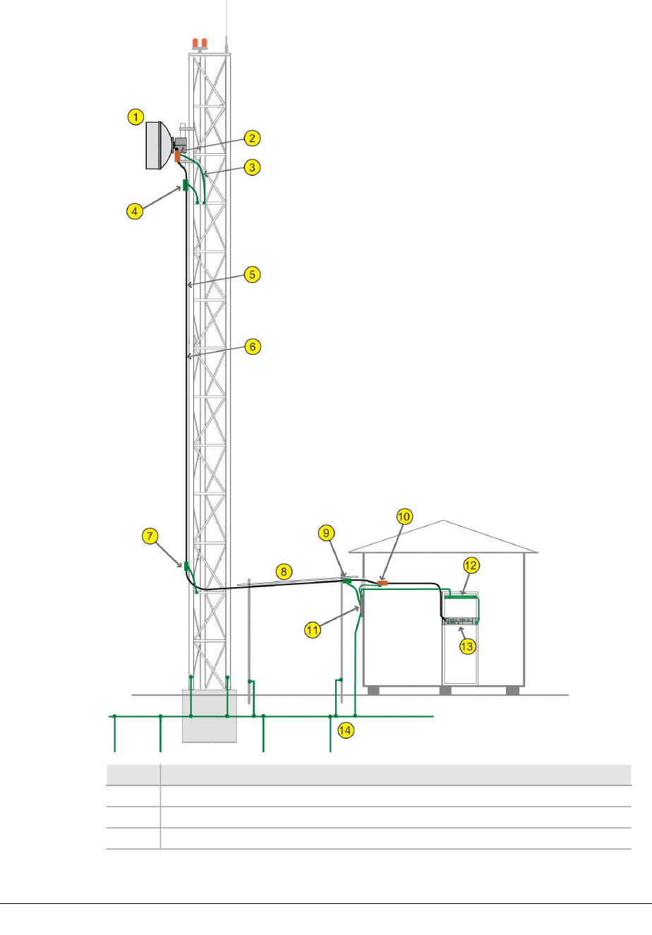
ECLIPSE INSTALLATION MANUAL
Table 2-4. Locations for Cable Grounds and Surge arrestors
Item Description
1ODU and antenna
2Lightning surge arrestor
3arrestor and ODU ground wires
260-668066-004 AUGUST 2013 61

VOLUME III, CHAPTER 2, ODU INSTALLATION
Item Description
4Cable ground
5The ODU cable must be supported by black cable (UV resistant) ties at
intervals no greater than 1m (3 feet). The ODU cable must not run
adjacent to tower lightning ground or electrical cables.
6If the height of the cable on the tower exceeds 50 m (165 feet), install
additional cable grounds at not more than 23 m (80 foot) intervals.
7Cable ground
8Cable carrier
9Cable ground
10 Lightning arrestor
11 External master ground bar
12 Rack ground bar
13 INU/INUe
14 Site grounding grid/radials
TypeN Cable Connectors
Ensure connectors are correctly fitted. Where crimp connectors are used, ensure the
correct crimp tool is used.
All TypeN con n ect ors used outdoors mu st be weat h erproofed. See
Weatherproofing on page 69 .
Jumper Cables
A jumper cable is required to connect from the RAC plug-in to the ODU cable, or
where fitted, to the lightning surge arrestor installed at the building entry.
lA 3m jumper cable is included with each RAC, fitted with an SMA male
connector at the RAC end and a TypeN female at the arrestor end.
lIf the run length is greater than 3m, an extension cable must be prepared to
extend the jumper reach. Use the ODU cable with TypeN connectors fitted at
both ends.
62 AVIAT NETWORKS

ECLIPSE INSTALLATION MANUAL
Installing Lightning Surge Arrestors
ODU 600 has an internal arrestor. An external arrestor at the ODU is not required
unless specified by the site owner or operator.
While an internal matrix-type arrestor is standard on ODU
600, an additi onal external ODU arrestor may still be required
to comply with local installation practices in regions that
experience severe l i ghtning strikes.
An arrestor should also be installed at building entry to provide added protection to
the indoor equipment, including that of other vendors. But where specified by the
site owner or operator, it must be installed.
For more information on recommended installation practices for lightning pro-
tection, refer to the Best Practices Guide.
For external arrestor installations, the supplied arrestor (Universal Lightning
Arrestor) is an in-line matrix type. It has a dc-blocked RF path with multiple pro-
tection stages in the parallel dc path. These arrestors are designed to withstand
repeated strikes and in the event they do fail, to hard-fail so as not to cause uncer-
tain or intermittent operation.
Refer to:
lLightning Arrestor Kit on page 63
lArrestor Installation at Building Entry on page 64
lArrestor Installation at the ODU on page 68
Lightning Arrestor Kit
The ULA (Universal Lightning Arrestor), type 108-1118B-A, is a compact cylindrical
inline arrestor.
Two versions are available, N-female to N-female, or N-male to N-female
The ULAs are bi-directional - they can be installed with either connector facing the
ODU.
The ULA kit includes a ground wire, crimp lug, washer, nut and O-ring. The ground
wire is terminated at one end for connection to the ULA, and is un-terminated at the
other to enable correct cutting-to-length and the fitting of the crimp lug.
260-668066-004 AUGUST 2013 63

VOLUME III, CHAPTER 2, ODU INSTALLATION
Figure 2-10. Universal Lightning Arrestor Kit
The ULA has repl aced the square style BGXZ and MHT
arrestors. Should installation data be r equired for these
earlier arrestors, refer to User Manual Rev.025, or earlier.
Arrestor Installation at Building Entry
This section describes installation of an arrestor at the building-entry end of the
ODU cable.
The building entry arrestor must be grounded to the master
gr ound bar at, or just below, the cable poi nt of entry. For
details on master ground bar location, refer to the Best
Practices Guide.
The ULA is intended for bulkhead-mounted on the wall-feed-through plate, or within
the cable tray just inside the building.
Refer to:
lBulkhead Installation Procedure: Grounded Copper Entryway Plate on page
64
lBulkhead Installation Procedure: Non-grounded / Non-master Entryway Plate
on page 66
lBuilding Entry Installation on page 67
lArrestor Installation at the ODU on page 68
Bulkhead Installation Procedure: Grounded Copper
Entryway Plate
The ULA ground wire is not required if the ULA is directly mounted to a properly
grounded copper entryway plate. This plate can either be a feed-through plate form-
ing the entryway itself, or a ground termination strip just inside the shelter entry-
way. The figure below illustrates the grounded entryway option.
64 AVIAT NETWORKS
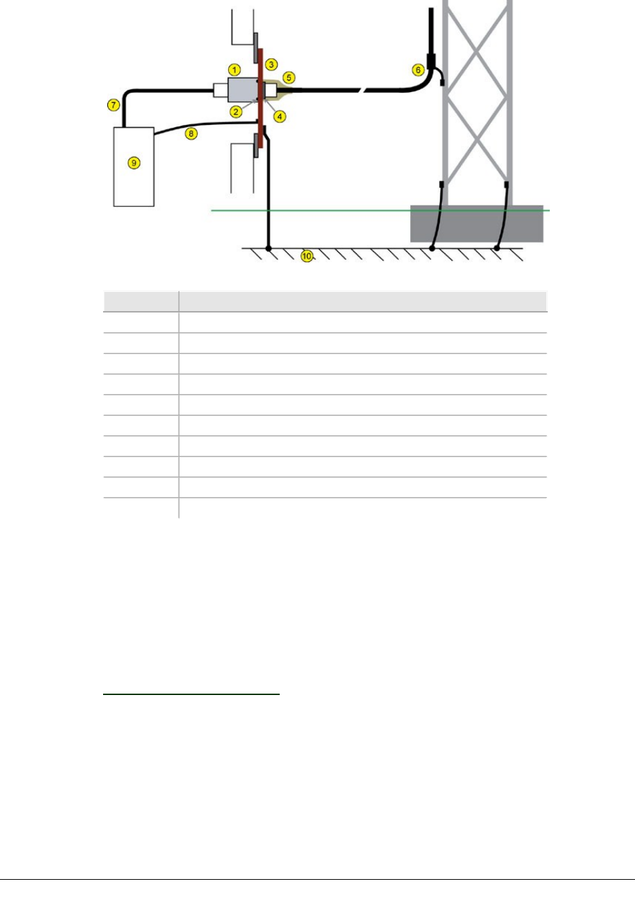
ECLIPSE INSTALLATION MANUAL
Figure 2-11. ULA Installed in Copper Plate Entryway
Item Description
1Lightning Surge arrestor
2Rubber seal
3Copper entryway plate
4Star washer and nut
5Mastic weatherproofing
6Cable ground kit
7Jumper cable
8Rack ground wire
9Equipment rack
10 Site ground system
Procedure
Carefully knock-out or drill for an N connector in the wall entryway plate. Where
provided, select a knockout with flats.
Install the ULA using the O-ring, star washer and nut provided. Check the O-ring is
correctly located within its groove, and up against the inside face of the plate.
Trim the ODU cable to length, fit an N male connector, and attach to the ULA.
Weatherproof the external N connector assembly using mastic and vinyl tape.
Weatherproofing on page 69.
Install a jumper cable from the ULA to the indoor radio unit.
260-668066-004 AUGUST 2013 65
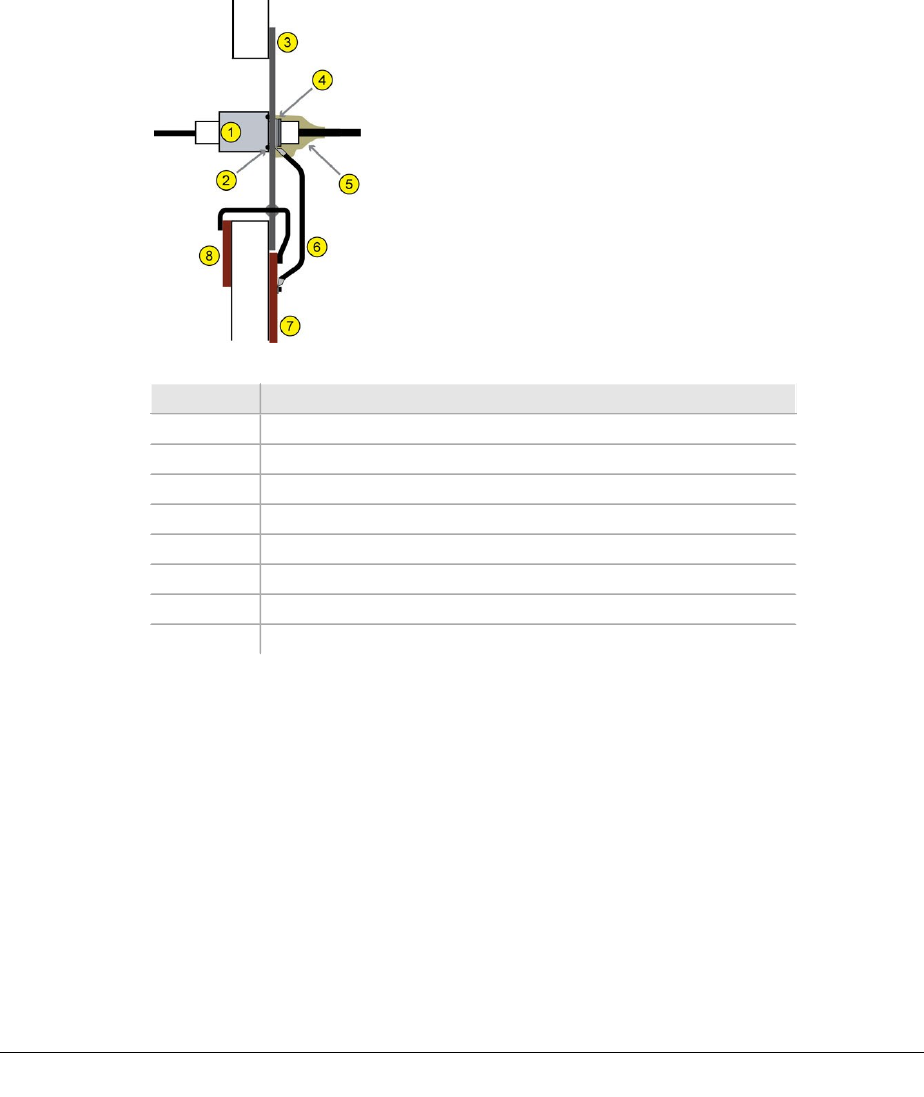
VOLUME III, CHAPTER 2, ODU INSTALLATION
Bulkhead Installation Procedure: Non-grounded / Non-
master Entryway Plate
The ULA ground wire is required if the ULA is mounted to an un-grounded entryway
plate or a plate made from non or poor conductive material (aluminum is considered
a poor conductor).
Figure 2-12. ULA Installed in Non-grounded Entryway Plate
Item Description
1ULA
2Rubber seal
3Entryway plate (not copper)
4Star washer and nut
5Mastic weatherproofing
6Ground cable
7External ground bar
8Internal master ground bar
Procedure
Carefully knock-out or drill for an N connector in the wall entryway plate. Where
provided, select a knockout with flats.
Install the ULA using the O-ring, ground wire, star washer and nut provided. Check
that the O-ring is correctly located within its groove, and up against the inside face
of the feed-through plate. Ensure that the ground wire cable is pointing down.
Trim the ground wire to length allowing a little slack in the wire when connected to
the external ground bar. Fit the crimp lug supplied to the trimmed end of the
ground wire and firmly bolt it to the ground bar.
Trim the ODU cable to length, fit an N-type male connector, and attach to the ULA.
66 AVIAT NETWORKS
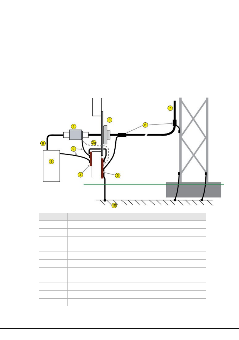
ECLIPSE INSTALLATION MANUAL
Weatherproof the external N connector assembly using mastic and vinyl tape. See
Weatherproofing on page 69.
Install a jumper cable from the ULA to the indoor radio unit.
Building Entry Installation
Determine where the ULA is to be located. This should be just inside the building,
and as close as practical to the entry point – no more than 1m (3ft) from the entry-
way. A location must be chosen that ensures that the body of the ULA will not be in
electrical contact with any metal structure (cable tray or similar support structure).
If necessary it should be mounted to the metal support structure using a ceramic or
porcelain
insulator.
Figure 2-13. ULA Installed Inside
Item Description
1Lightning Surge arrestor
2Ground wire
2a Preferred path for ULA ground wire
3Wall gland
4Internal master ground bar
5External ground bar
6Cable ground kit
7ODU cable
8Indoor unit to arrestor jumper cable
9Equipment rack
10 Site ground system
260-668066-004 AUGUST 2013 67

VOLUME III, CHAPTER 2, ODU INSTALLATION
Procedure
Fit the lugged end of the ground wire to the N-female end of the ULA (end with
'flats' on the thread) and securely fasten using the star washer and nut supplied.
Trim the ODU cable to length, fit an N male connector, and attach to the ground-
wire end of the ULA.
Trim the ULA ground wire so there is just a little slack in the wire when connected to
the master ground bar or external ground bar. Fit the crimp lug supplied and firmly
bolt to the ground bar. (Where possible connect to the external entryway ground bar
- surge-related grounds should go directly to the external ground bar).
Install a jumper cable from the ULA to the indoor radio unit.
Note:
1. At sites where the arrestor cannot be located adjacent to building entry, the
arrestor ground wire must be returned directly to the master ground bar - it
must not be connected to the rack ground or similar.
2. For an external ground bar ground connection, apply copper-based
protective grease around the nut/bolt/lug of the ground-bar end of the
ground wire.
3. If the arrestor is located outside the building, connectors must be
weatherproofed. Refer to Weatherproofing on page 69. After weatherproofing,
apply copper-based protective grease around the nut/bolt/lug of the arrestor
end of the ground wire.
Arrestor Installation at the ODU
This procedure applies to the ODU 600 where an external arrestor is to be installed.
ULA Installation Procedure
1. Install ULA onto ODU N-type female connector. ULA model must be Type-N
male to Type-N female.
2. Fit ODU cable to the ULA.
oThe ODU cable should be run in a downward direction from the ULA to the
tower.
oEnsure the ODU cable is supported within 0.6m (2 ft.) of the ULA. The
cable must be run so as to not stress the mechanical interface of the ULA to
the ODU connector. If necessary (to provide easier ODU cable running)
install an additional Type-N 90 degree adaptor to the ULA.
3. Complete required weatherproofing. See Weatherproofing on page 69.
68 AVIAT NETWORKS

ECLIPSE INSTALLATION MANUAL
Weatherproofing
Weatherproofing kits are included with the ODU cable and lightning surge arrestors.
Two types of weatherproofing media are supplied. Refer to:
lMastic Tape on page 69
lSelf Amalgamating Tape on page 70
Mastic Tape
The ODU cable ground kits include rolls of vinyl and butyl mastic tape. A two-layer
wrap process is recommended:
lAn initial layer of mastic. It is this tape that provides the weatherproofing.
lA top layer or layers of vinyl tape to support good amalgamation and
adhesion of the mastic tape and to provide UV protection.
Where mastic tape is used to weatherproof connectors a
three-layer process is recommended, where a center layer of
vinyl tape is applied befor e the masti c to facilitate easy strip-
back when connector disconnection is required. Speci al atten-
tion must be given to ensuring the masti c tape seals cleanly
to the primary surfaces, such as the cable jacket.
Wrapping Guidelines, Mastic (Butyl) Tape
To weatherproof connectors start at 1. To weatherproof a cable ground start at 3.
1. Ensure connectors are firmly hand-tightened, dry, and free from all grease and
dirt. If necessary, clean with rag lightly moistened with alcohol-based cleaner.
2. Using vinyl tape, pre-wrap just the center section of the connector barrel - the sec-
tion to which access will be needed if the connector ever needs to be undone. Use a
25% overlay when wrapping. To avoid curl-back do not stretch the tape too tightly at
the end point.
On an ODU connector, leave at least two-thi rds of the smooth
length of the barrel clear of pre-wrap vi nyl tape, to ensure
the mastic tape has sufficient ar ea of direct gr i p.
3. Wrap with mastic tape using a half to 2/3rds width overly, and ensure there is at
least a 25 mm (1”) attachment onto the primary surfaces to either side (cable jacket,
ground wire, connector).
For a cable ground, ensure there is no possibility of water penetrating between the
ODU cable and its ground wire by first applying and forming mastic tape around the
260-668066-004 AUGUST 2013 69

VOLUME III, CHAPTER 2, ODU INSTALLATION
ground wire where it lies against the ODU cable. The ground wire must always exit
from the bottom of the wrap.
4. Starting at the bottom, wrap the mastic tape in an overlapping pattern, slightly
stretching the tape as you wrap. By wrapping from the bottom you help to ensure
there are no ridges or pockets for water to sit in.
There must be a f ull seal of mastic tape onto the primary sur-
face for weatherproofing i ntegri ty.
5. Firm over by hand and squeeze the tape along its edges to form it to the con-
nection. Use tear-off section of the mastic tape backing to protect your hands. Check
that there is no possibility of water entry before proceeding to the next step.
6. Cover the mastic tape with layers of vinyl tape.
7. For a cable ground, wrap from the bottom, with the first layer extending 25mm
(1”) each side of the mastic tape. Subsequent layers must extend no less than 25mm
(1”) each side of the previous layer.
8. Wrap the tape in an overlapping pattern at not less than a half width, slightly
stretching the tape is you wrap, except do not do not stretch for the last two turns of
the top layer to prevent curl-back.
9. Squeeze the completed wrapping to ensure all layers are firm.
To avoid displacement of the masti c tape, do not stretch the
final layer(s) of vinyl tape across shar p corners and edges.
Self Amalgamating Tape
Self amalgamating tape binds to the host and bonds between layers to provide a con-
tinuous seal. It is especially useful in tight locations.
Wrapping Guidelines, Amalgamating Tape
1. Ensure the connectors are firmly hand-tightened, dry, and free from all grease and
dirt. If necessary, clean with a rag lightly moistened with alcohol-based cleaner.
2. Apply the tape with tension (slight stretching), using at least a 75%
overlay.
3. Where possible, apply the tape 25mm (1”) past the ends of the connector barrels
to ensure the weatherproof bond extends beyond the areas requiring protection. The
tape must be applied in such a way that the sealing is robust (no obvious weak
points).
4. To avoid curl-back, do not stretch the tape too tightly at the end.
5. To assist UV protection, a post-wrap using vinyl tape can be applied.
70 AVIAT NETWORKS

ECLIPSE INSTALLATION MANUAL
Chapter 3. INU and INUe
Installation
The INU and the INUe are the indoor units for the Eclipse Node.
This chapter includes:
lINU/INUe Overview on page 72
lInstallation Requirements on page 78
lInstallation Procedure on page 80
lPlug-in Installation on page 83
lINU/INUe Cable Assemblies on page 86
CAUTION:Do not turn power off within 10 minutes of initial
INU/INUe turn-on, or initial turn-on after a new compact flash card is
installed.
CAUTION:There must be a minimum of 50 mm (2”) of side spacing
from the INU/INUe to any rack panels, cable bundles or similar, and
50 mm (2”) of space to the front and back of the RF section to ensure
proper ventilation.
260-668066-004 AUGUST 2013 71
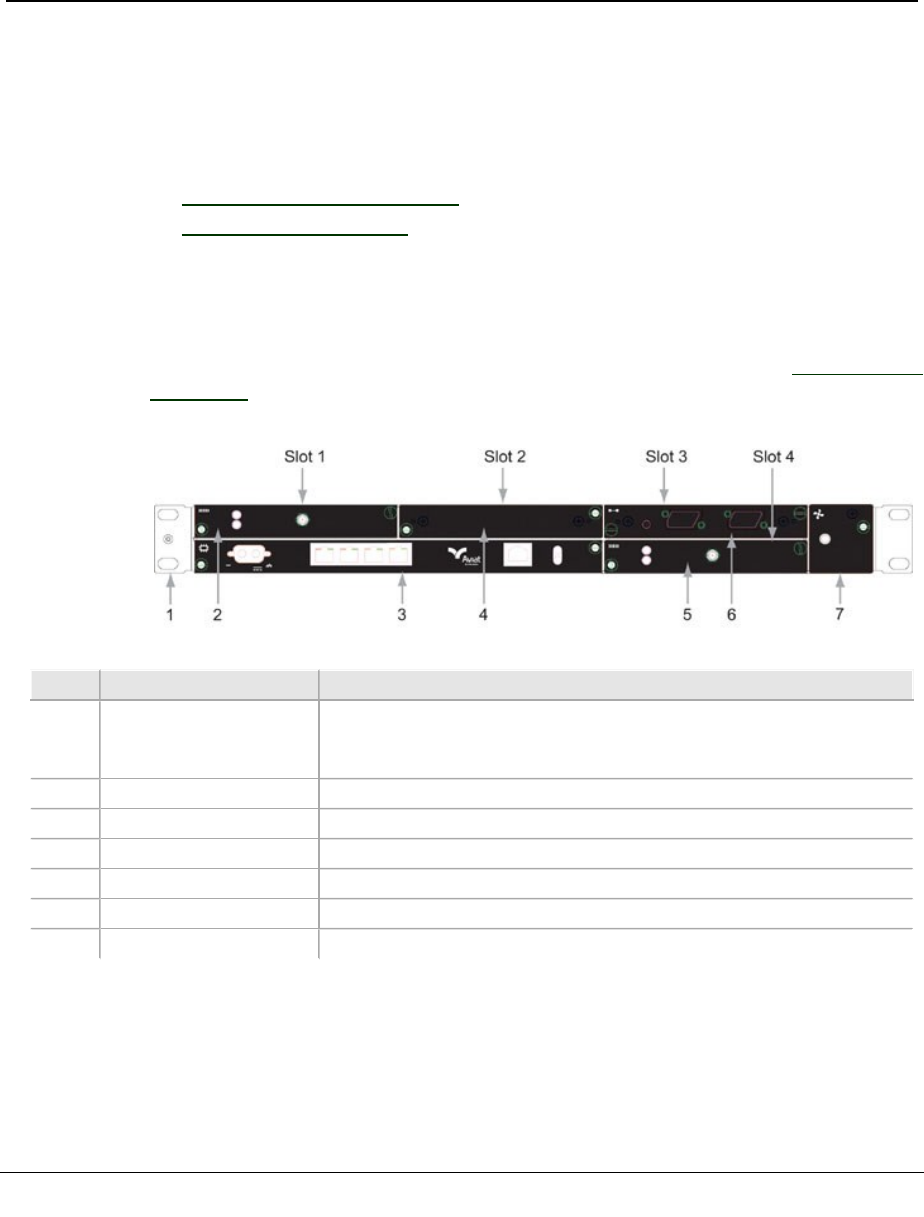
VOLUME III, CHAPTER 3, INU AND INUE INSTALLATION
INU/INUe Overview
The INU/INUe is a rack-mounted unit that pairs with one or more ODUs. An
INU/INUe comprises a chassis and plug-ins.
Dedicated slots are provided for the NCC and FAN plug-ins, and either four slots
(INU) or ten slots (INUe) for optional RAC, DAC, AUX and NPC plug-ins.
Refer to:
lFront Panel Layout on page 72
lPower Supply on page 72
Front Panel Layout
An INU front panel is shown. For information on the plug-in cards see Plug-in Cards
on page 18 .
Figure 3-1. Typical INU Front Panel Layout
No Item/Label Description
1Rack Ear and
grounding stud
Rack attachment bracket for the IDC. One ear has a combined
ESD and IDC grounding stud. The ears can be fitted either side,
which provide flush-with-rack-front mounting.
2RAC RAC fitted in slot 1
3NCC Mandatory Node Control Card (dedicated slot)
4Blank Panel Blanking panel fitted to slot 2
5RAC RAC fitted in slot 4
6DAC 16x 16xDS1 DAC fitted in slot 3
7FAN Mandatory fan plug-in (dedicated slot)
Power Supply
72 AVIAT NETWORKS

ECLIPSE INSTALLATION MANUAL
The DC power supply must be UL or IEC compliant for SELV
(Safety Extra Low Voltage) output (60Vdc maximum l i mi ted).
INUs require a -48Vdc power supply (+ve earth), but will operate to specification
over a voltage range of -40.5 to -60Vdc.
The return (+ve) pin on the NCC and NPC power supply connectors is clamped to
chassis ground via polarity-protecting power FETs.
lNCC and NPC power inputs are reverse polarity protected (the input fuse will
not blow if polarity is reversed).
Where operation from a +24 Vdc PSU is required, the plug-in PCC option provides
voltage conversion from + 24 (19 to 36) Vdc to -56 Vdc for connection to the NCC -
48Vdc input. -56 Vdc represents the typical float voltage for a battery-backed -48
Vdc supply.
Power Consumption and INU Load Maximums
Total power consumed is dependent on the number and type of plug-in cards, and
the number of ODU 600s supported.
INU loading maximums, the number and type of RACs and DACs that can be
installed in an INU, are determined by the load capacity and temperature limits of
the DC converter in the NCC, which supplies various DC rails to the plug-in cards.
lODUs and FANs are not powered via the NCC converter, meaning the ODU
does not impact INU link loading. Its DC supply is taken from the -48 Vdc
power supply input connector.
However, if a PCC is installed for +24 Vdc operation, the INU cards and associated
ODUs are supplied from the PCC, meaning PCC power limits are determined by the
INU cards and by the number of ODUs supported.
lA PCC should always be installed to receive maximum FAN cooling. This
means it should be installed in the immediate FAN-side slots in an INU/INUe.
Power Consumption
The table below lists nominal power consumption figures for Eclipse cards. Use these
together with the ODU 600 consumption figures in the following tables to determine
total nodal power consumption.
Power consumption figures are for a -48 Vdc supply voltage at normal room ambi-
ents.
Table 3-1. Typical Plug-in Power Consumptions
Item Consumption
RAC 60E 12W
DAC 16xV2, 4x, 3xE3/DS3,
3xE3/DS3M
2.5W
DAC 155o, 2x155o, 2x155e,
155oM, 155eM
4W
260-668066-004 AUGUST 2013 73

VOLUME III, CHAPTER 3, INU AND INUE INSTALLATION
Item Consumption
DAC GE3 13W
NCC 11W
NPC 8W
AUX 1W
FAN 1RU 2W
FAN 2RU 2W
ODU 600
ODU 600 power consumption figures apply to both standard and high power oper-
ation.
Table 3-2. ODU 600 Power Consumption
BAND Average Power
Consumption W
Max Power Con-
sumption W
5.8/6 GHz 50.2 59.2
Node Card Maximums
The following maximums are applicable to operation using SW release 5.04 or later.
lAn NPC must be fitted in an INUe where specified below. The NPC provides
power supply load sharing with the NCC, allowing the overall loading to be
increased. Should the NPC fail, airflow from the 2RU FAN is increased to
compensate.
When planning the number and type of cards to be installed in an INUe or INU, the
following rules must be observed. Individual card consumptions are detailed under
Power Consumption.
CAUTION:The loading rules below must be observed by the installer -
there is no built-in mechanism to report or limit an incorrect dimen-
sioning of power supply consumption.
INUe Loading Rules for Operation up to 55ºC (131ºF)
The following loading rules must be followed when dimensioning the total power con-
sumption of an INUe that is required to operate in ambient temperatures up to 55ºC
(131ºF):
lIf the total power consumption of all cards installed exceeds 85 watts, an NPC
must be fitted, and a 2RU FAN card must be fitted.
lWith this configuration confirmed the maximum INUe loading enabled is 125
watts. The one exception/condition is that the combined installed total of DAC
GE3 cards must not exceed four.
CAUTION:55ºC (131ºF) operation does not apply to the PCC. Oper-
ational ambient temperatures with a PCC installed must not exceed
450C (1130F).
74 AVIAT NETWORKS

ECLIPSE INSTALLATION MANUAL
INUe Loading Rules for Operation at 45ºC (113ºF)
The following loading rules must be followed when dimensioning the total power con-
sumption of an INUe that is operating in ambient temperatures that do not exceed
45ºC (113ºF):
lIf the total power consumption of all cards installed exceeds 85 watts, an NPC
must be fitted, and a 2RU FAN card must be fitted.
lWith this configuration confirmed the maximum INUe loading enabled is 150
watts. The exceptions/conditions to this rule are:
oINUe loading is limited to 140 watts if the installed total of DAC GE3 cards
exceeds two.
oThe combined installed total of DAC GE3 cards must not exceed four.
Table 3-3. Example Compliant INUe Configurations (5.04 SW or later)
Configuration Total Card
Consumption
Ambient
Max Temp
Max Power
Con-
sumption
NCC, NPC, 6xRAC 60E, 2xDAC GE3, AUX 120W +55 ºC 125W
NCC, NPC, 6xRAC 60E, 2xDAC GE3, AUX 150W +45 ºC 150W
NCC, NPC, 6xRAC 60E, 2xDAC GE3, DAC 155oM 124W +55 ºC 125W
NCC, NPC, 4xRAC 60E, 2xDAC GE3, 2xDAC 16x, AUX 121W +55 ºC 125W
INU (1RU) Loading Rules
The INU (1RU) chassis should not be loaded above the follow limits:
l65 watts total for operation up to 45ºC
l50 watts total for operation up to 55ºC
Elevated ambient temperatures shoul d be avoided. The ambi-
ent temperature is the ai r temperature i n the immediate oper-
ating environment of the chassis, which if i nstal l ed in a r ack,
is the ambi ent applying to its locati on within the rack.
CAUTION:The ambient temperature maximums must not be
exceeded. Over-temperature operation is a primary factor affecting
long term component reliability.
PCC +24 Vdc Operation
The PCC is for use with standard +24 Vdc (-ve grounded) battery-backed power sup-
ply systems.
lOne PCC supports a maximum three ODUs, plus any combination of RACs
and DACs.
lThe PCC +ve and -ve input terminals are isolated from chassis (ground). The -
ve input is grounded by the -ve grounded power supply connection.
lThe PCC 20A fuse is fitted in the +ve input. It is a PCB mount type and is not
field replaceable.
260-668066-004 AUGUST 2013 75
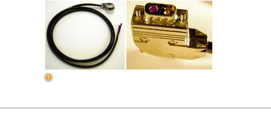
VOLUME III, CHAPTER 3, INU AND INUE INSTALLATION
lReverse polarity protection is provided. The PCC will automatically recover
from a reverse polarity connection - the fuse will not blow. Over temperature
thermal protection is included.
lThe PCC load maximum is 200 Watts. Use the power consumption data in the
preceding section to determine the maximum number of cards and ODUs that
an be supported.
lAmbient temperatures must not exceed 450C (113F). The PCC should always
be installed next to the FAN card to get best air flow cooling.
lThe PCC conversion efficiency is nominally 10%. To determine the power
consumed by the PCC, use a figure of 10% of the power consumed by the
INU/INUe cards and ODUs.
lWhen installed in an INUe the INUe must be fitted with the 2RU FAN module.
lThe PCC must be connected to the NCC before applying power to the PCC to
avoid a current-inrush trip (overload) on the PCC.
lThe PCC can be plugged into any INU/INUe option slot. It is not connected to
the backplane and its function is not monitored within Portal.
lWhere an NPC is fitted, two PCCs are required for +24 Vdc operation, one for
the NCC, the other for the NPC. This means an INUe must be used for NCC +
NPC operation.
lIf the PCC front-panel LED is not lit, it indicates the existence of abnormal
conditions such as output under-voltage, output over-voltage, loss of input
power, output over-current, or open input fuse.
Power Cables
The INU power cable is supplied in the IDC Installation Kit. It is supplied with a D-
sub M/F 2W2 connector fitted at one end and wire at the other. The cable is nom-
inally 5m (16ft), and the wires are 4mm2 (AWG12).
The cable is used for -48 Vdc connections to an NCC or NPC, or for +24 Vdc con-
nections to a PCC.
The blue wire must be connected to live (-48 Vdc or +24 Vdc); the black wire to
ground (+48 Vdc or -24 Vdc).
Figure 3-2. Power Cable and Connector
CAUTION:DC power connector can be shorted inadvertently if applied
at an angle. Always insert with correct alignment.
76 AVIAT NETWORKS

ECLIPSE INSTALLATION MANUAL
The PCC is supplied with a power cable to connect to an NCC or NPC.
This cable is fitted with a D-sub M/F 2W2 connector at each end. Note that a stand-
ard power cable is not included for the reason the cable supplied with an NCC (or
NPC) is not used when powered from a PCC, so the cable is re-used as the power
input cable for the PCC.
Fuses
The NCC and NPC are fitted with a fast-acting 25A fuse fitted on the PCB behind the
power cable connector.
The PCC is fitted with a fast-acting PCB-mounted 20A fuse.
NCC, NPC and PCC fuses are not field-replaceable.
260-668066-004 AUGUST 2013 77

VOLUME III, CHAPTER 3, INU AND INUE INSTALLATION
Installation Requirements
This table lists typical INU Installation requirements.
Function/Requirement Details
Restricted access The INU/INUe and its associated dc power supply must be installed in
a restricted access area such as a secure equipment room, closet, or
cabinet.
Required Rack Space The INU requires 44.5mm (1RU) of vertical rack space and 300mm
rack depth. The INUe requires 89mm (2RU) vertical rack space.
Ventilation The INU/INUe requires unobstructed air passage to each side for
ventilation purposes. There must be a minimum of 50mm (2”) of
side spacing to any rack panels, cable bundles or similar. No space
above or below is required for ventilation purposes.
Maximum Ambient
Temperature
The INU/INUe is specified for a maximum ambient temperature
(Tmra) of +55°Celsius (131° Fahrenheit). Conditions apply - see
Power Supply on page 72. The maximum ambient temperature
(Tmra) applies to the immediate operating environment of the INU,
which if installed in a rack, is the ambient applying to its location
within the rack.
Physical stability Ensure that adding an INU/INUe to a rack does not adversely impact
the physical stability of the rack.
Power supply -48 Vdc The INU (NCC and NPC) has the +ve pin on its dc power supply
connector connected to the chassis.
It must be used with a -48Vdc power supply which has a +ve
ground; the power supply ground conductor is the +ve supply to the
INU.
There must be no switching or disconnecting devices in the ground
conductor between the dc power supply and the point of connection
to an INU/INUe.
Power Supply +24 Vdc A PCC is required to provide a +24 Vdc to -48 VDC conversion. The dc
power supply supplying the PCC must be -ve grounded.
There must be no switching or disconnecting devices in the ground
conductor between the dc power supply and the point of connection
to a PCC.
Power Supply Location The INU/INUe must be installed in the same premises as its dc power
supply and be located in the same immediate area (such as adjacent
racks or cabinets) as any other equipment that is connected to the
same dc power supply.
78 AVIAT NETWORKS

ECLIPSE INSTALLATION MANUAL
Function/Requirement Details
Power Supply
Compliance and Loading
The dc power supply must be UL or IEC compliant for a SELV output
(60Vdc maximum).
Check to ensure that connection of an Eclipse system to an existing
dc supply does not overload the supply, circuit protection devices and
wiring.
Where a new dc power supply is to be installed for an Eclipse Node,
the power supply should be rated to supply:
- 12.5A for the INU
- 25A for the INUe
- 15A for the PCC
Cable routing Eclipse tributary, auxiliary and NMS cables are not to be routed with
any AC mains power lines. They are also to be kept away from any
power lines which cross them.
Grounding The INU must be grounded to the station or master ground, which
must be the same ground as used for the dc power supply. Normally
this is achieved by grounding the INU to the ground bar in its
equipment rack or frame. This bar is most often located to one side of
the rack or at rack top or bottom. In turn, the ground bar is grounded
to the station ground.
260-668066-004 AUGUST 2013 79

VOLUME III, CHAPTER 3, INU AND INUE INSTALLATION
Installation Procedure
1. Fit the rack mounting brackets to the chassis with the grounding stud to left
or right side for the most direct ground wire path to the rack ground bar.
2. Locate the INU/INUe in the equipment rack and secure it using four No.12
Phillips dome-head screws from the IDC installation kit.
3. Ground the INU/INUe from the grounding stud to the rack/frame ground
bar using a length of 4mm2 (AWG12) green PVC insulated stranded copper
wire with a suitably sized ground lug at the ground bar end (supplied by the
installer). The grounding stud accommodates ground cables up to 16 mm2
(AWG 6). The stud also provides jack plug connection for a wrist strap.
4. If the equipment rack/frame requires grounding, use 16mm2 (AWG6) wire
from its ground bar to the station ground.
Grounding Safety:
oDo not assume that an existing rack or mounting frame is correctly
grounded. Always check the integrity of the ground connections, which
must include a check through to the master ground for the station, which
should be located at the point of cable entry to the equipment building.
Ground wires must provide a direct, low impedance path to the master
ground bar.
oDo not connect other equipment to the same grounding cable as the INU.
Each item of equipment in a rack must be separately grounded to the rack
ground bar.
oThe INU must be located in the same immediate area (adjacent
racks/cabinets) as all other equipment with a (ground) connection to a
common DC supply source.
5. Install the plug-ins in their assigned slot positions, and check that their
front panels are flush-fitted (not protruding) and held secure by their
fasteners. Ensure unused slots are covered by blanking panels.
oInstall the CompactFlash (CF) card in the NCC; insert in the socket on
the right side of the PCB.
oThe CF card holds configuration, software load, and license data.
oEach CF card is identified by a unique serial number; which is the license
number for the Eclipse terminal.
6. Fit the supplied jumper cable between the RAC and ODU cable, or where
required to a lightning surge arrestor. Secure the cable within the rack/frame
using cable ties or similar. If the jumper cable is too short, make an
extension cable.
7. Fit NMS cables, DAC tributary cables, and where required, AUX cables. For
data on the cable sets, refer to INU/INUe Cable Assemblies on page 86.
80 AVIAT NETWORKS

ECLIPSE INSTALLATION MANUAL
The following steps describe the procedure for installing the power cable, and pre-
paring for power-on. Do not connect the power until all steps have been completed.
8. Run the supplied power cable through to the power pick up point, which
will normally be at a circuit breaker panel in the rack. A circuit breaker (or
fuse) should have a capacity of 12A for the INU and a 25A for the INUe,
however these ratings can be adjusted in line with the number of cards
installed, and hence power consumption. For power consumption data, see
Power Supply on page 72.
9. For a -48 Vdc supply, connect the blue wire to -48Vdc (live), and the black
wire to ground/+ve. (Power input on the NCC and NPC is polarity
protected).
10. For a +24 Vdc supply, connect the blue wire to +24Vdc (live), and the black
wire to ground/-ve. (Power input on the PCC is polarity protected).
11. Measure the voltage on the dc power connector.
oFor -48 Vdc operation the voltage should be -48Vdc, +/-2Vdc for a non
battery floated supply, and nominally -56 Vdc for a battery floated supply.
(Limits are -40.5 to - 60 Vdc).
oFor +24 Vdc operation the voltage should be 24 +/- 2Vdc for a non battery
floated supply, and nominally 30 Vdc for a battery floated supply.
(Operating limits are 20 to 36 Vdc).
CAUTION:This product meets the global product safety requirements
for SELV (safety extra low voltage) rated equipment and the input
voltage must be guaranteed to remain within the SELV limits (60V
maximum) in the event of a single internal fault.
Always check the integrity of the dc power supply to an INU/INUe
right to its source. Never assume that the supply provided to the pick-
up point in a rack is correct.
Eclipse dc power, IF, tributary, auxiliary and NMS cables are not to be
routed with any AC mains power lines. They are also to be kept away
from any AC power lines which cross them.
12. Carry out a complete check of the installation. If all is correct, and the ODU
600 installation has likewise been completed and checked, the INU and
ODU 600 are ready for power-on.
oIf a PCC is installed, ensure the PCC to NCC/NPC cable is correctly fitted
before power-on.
CAUTION:Once powered up the ODU(s) will be transmitting with the
pre-configured or ex-factory frequency and power settings unless the
start-up transmit mute option has been invoked. (All ODUs shipped
ex-factory have the transmit-mute set as the default unless oth-
erwise specified).If frequency and power settings are not correct,
interference can be caused to other links in the same geographical
area.
13. Turn power on. For -48 Vdc connect the power cable to the NCC, and to the
NPC where fitted. For +24 Vdc operation, connect to the PCC input.
CAUTION:Do not turn off an INU/INUe within 10 minutes of initial
turn-on, or initial turn-on after a new compact flash card is installed.
260-668066-004 AUGUST 2013 81

VOLUME III, CHAPTER 3, INU AND INUE INSTALLATION
CAUTION:2W2 DC power connectors can be shorted inadvertently if
applied at an angle. Always insert with correct alignment.
CAUTION:Ambient temperatures must not exceed 550C (1310F). If
installed in a rack cabinet, it is the ambient within the cabinet.
Next Step: The Eclipse INU with ODU 600 is ready for configuration and antenna
alignment.
82 AVIAT NETWORKS
ECLIPSE INSTALLATION MANUAL
Plug-in Installation
Installing or changing out a plug-in is a straightforward process.
lThe table below lists plug-in requirements at installation or subsequent
upgrade.
lUnless specified by the customer, plug-ins will not be installed in an
INU/INUe at shipment. Instead, each is individually packed within the
shipping box.
For a description of the plug-ins, see Plug-in Cards on page 18.
For information on user-interface connector and cable data, refer to INU/INUe Cable
Assemblies on page 86.
Table 3-4. Plug-in Requirements
Function/Requirement Priority Details
Slot Assignment
All slots filled All slots must be filled with either a plug-in or a blanking
panel. Failure to do so will compromise EMC integrity and
distribution of FAN cooling air.
Universal slots
1-4 on an INU
1-6 on an INUe
RAC, DAC, and AUX plug-ins can be fitted in any universal
slot.
Restricted slots
7-9 on an INUe
DAC, and AUX plug-ins can be fitted in any restricted slot.
The exceptions are the DAC 155oM, DAC 155eM, and AUX,
which must only be installed in slots 1 to 6 when they are to
be configured to carry/access Eclipse NMS, otherwise they
can be installed in slots 7 to 9.
Dedicated slots The NCC, FAN, and NPC plug-ins have dedicated slots.
Protected RACs INUe Protected RACs (or ring-protected RAC with DAC 155oM)
must only be installed in ‘above and below’ slots as indicated
by the red arrows.
AUX Multiple AUX plug-ins can be installed per INU/INUe.
NPC Only one NPC is required to provide the NCC protection
option. An NPC must be installed in slot 4 of an INU, or slot
10 of an INUe. If an NPC is not installed in an INU, slot 4 is
available as a universal slot.
Installing / Changing Plug-ins
ESD grounding strap Always connect yourself to the INU/INUe with an ESD
grounding strap before changing or removing a plug-in.
Failure to do so can cause ESD damage to the plug-ins. Avoid
hand contact with the PCB top and bottom.
260-668066-004 AUGUST 2013 83
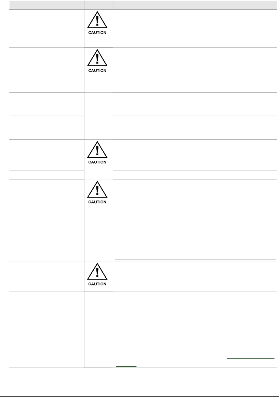
VOLUME III, CHAPTER 3, INU AND INUE INSTALLATION
Function/Requirement Priority Details
Finger-grip fasteners Plug-ins must be withdrawn and inserted using their finger-
grip fasteners/pulls. Never withdraw or insert using attached
cables, as damage to the plug-in connector and its PCB
attachment can occur. If not complied with, the Aviat
Networks warranty may be voided.
Hot-swappable Plug-ins are hot-swappable.
- Removal of an in-service payload plug-in will interrupt its
traffic.
- Removal of the NCC will affect all traffic - unless pro-
tected by an NPC.
- Removal / replacement of the FAN does not affect traffic.
Engaging backplane
connector
When installing a plug-in, ensure its backplane connector is
correctly engaged before applying sufficient pressure to
bring the plug-in panel flush with the front panel.
Revision time lag When swapping or installing plug-ins, up to 60 seconds can
be required for the INU/INUe to show its revised status via
the front panel LEDs, or via Portal.
EMC integrity Plug-ins and blanking panels are held in place by captive
finger-screws. Ensure the finger-screws are fastened as
failure to do so may compromise EMC integrity and fan
cooling.
RACs
Connecting and
disconnecting the ODU
cable at the RAC
Never disconnect or reconnect an ODU cable to a RAC
without first turning the power off to the INU or withdrawing
the RAC from the backplane.
NOTE: The ODU cable provides the power feed to the
ODU. Arcing during connection and disconnection at the
RAC on a live RAC can cause damage to connector contact
surfaces. Power spikes caused by live connection and dis-
connection may also cause errors on other traffic passing
through the INU/INUe. The only exception to live dis-
connection and connection should be for checks of pro-
tected operation at link commissioning.
Removing RAC from a
powered INU
When removing a RAC from a powered INU, always the
disengage the RAC from the backplane before disconnecting
its ODU cable. Similarly before inserting an RAC, always
reconnect the ODU cable before engaging the backplane.
RAC combinations for
INUe
An INUe can be fitted with a maximum of six RACs for one of
the following combinations:
- Six non-protected links
- One protected/diversity link plus four non-protected links
- Two protected/diversity links plus four non-protected
links
- Three protected/diversity links
Before installing more than four RACs refer to the Power
Consumption and INU Load Maximums in Power Supply on
page 72.)
84 AVIAT NETWORKS
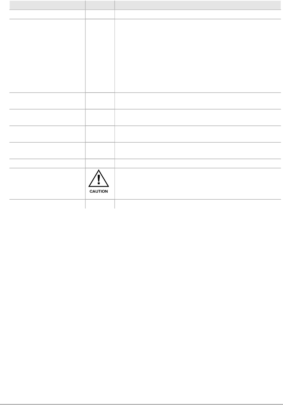
ECLIPSE INSTALLATION MANUAL
Function/Requirement Priority Details
DACs
DAC combinations DACs can be fitted singly or in combination to provide a mix
of interface types and capacities provided they have a
common backplane configuration. The backplane can be set
for:
- 1.5 Mbit/s / DS1
- 3 Mbit/s / DS3
- 155 Mbit/s / OC3
Mux version DACs allow a mix of interfaces from a common
DS1 backplane configuration.
Increasing node capacity To achieve a greater node capacity, two or more INUs can be
interconnected via a DAC option.
Interface Protection
(electrical DACs)
Line (interface) protection is supported for paired DS1, DS3
and OC3 electrical DACs.
Interface Protection
(optical DACs)
Line (interface) / card protection is supported for paired OC3
optical DACs.
Interface Protection, Eth-
ernet DAC GE3
Interface / card protection is supported for paired DAC GE3
cards.
General
Antistatic bags Enclose spare plug-ins, or plug-ins to be returned for service,
in an antistatic bag. When handling a plug-in to or from an
antistatic bag, do so at the INU/INUe and only when you are
connected to the INU/INUe via an ESD ground strap.
Spare blank panels Keep any removed blanking panels for future use.
260-668066-004 AUGUST 2013 85

VOLUME III, CHAPTER 3, INU AND INUE INSTALLATION
INU/INUe Cable Assemblies
CAUTION:Eclipse tributary, auxiliary and NMS cables are not to be
routed with any AC mains power lines. They are also to be kept away
from any power lines which cross them.
For safety reasons tributary, auxiliary and NMS cables should not be
connected to outside plant.
Use approved surge suppression equipment when connecting to un-
protected external inputs and outputs.
Refer to:
lDAC Trib Connectors and Cables on page 86
lNMS Connectors and Cables on page 97
lAuxiliary and Alarm Connectors and Cables on page 99
DAC Trib Connectors and Cables
This section provides cable and connection data for:
lDAC 16xV2 Cable and Connector Data on page 86
lDAC 4x Cable and Connector Data on page 92
lDAC GE3 Ethernet RJ-45 Cables on page 94
lDAC Optical Cable and Connector Data on page 95
lDAC 155eM Cables on page 97
DAC 16xV2 Cable and Connector Data
Refer to:
lDAC 16xV2 HDR-E50 To 24 AWG Free End Cable Assembly on page 86
lDAC 16xV2 HDR-E50 To BNC Cable Assembly on page 87
lDAC 16xV2 HDR-E50 To RJ-45 Cable Assembly on page 88
lDAC 16xV2 HDR-E50 To Free End Y-Cable Assembly on page 89
lDAC 16xV2 HDR-E50 To BNC Y-Cable Assembly on page 90
DAC 16xV2 HDR-E50 To 24 AWG Free End Cable Assembly
The assemblies provide balanced 120 ohm connections on cable lengths of 3m, 10m,
15m or 32m. The wire is intended for use with wire-wrap or insulation displacement
termination blocks.
86 AVIAT NETWORKS
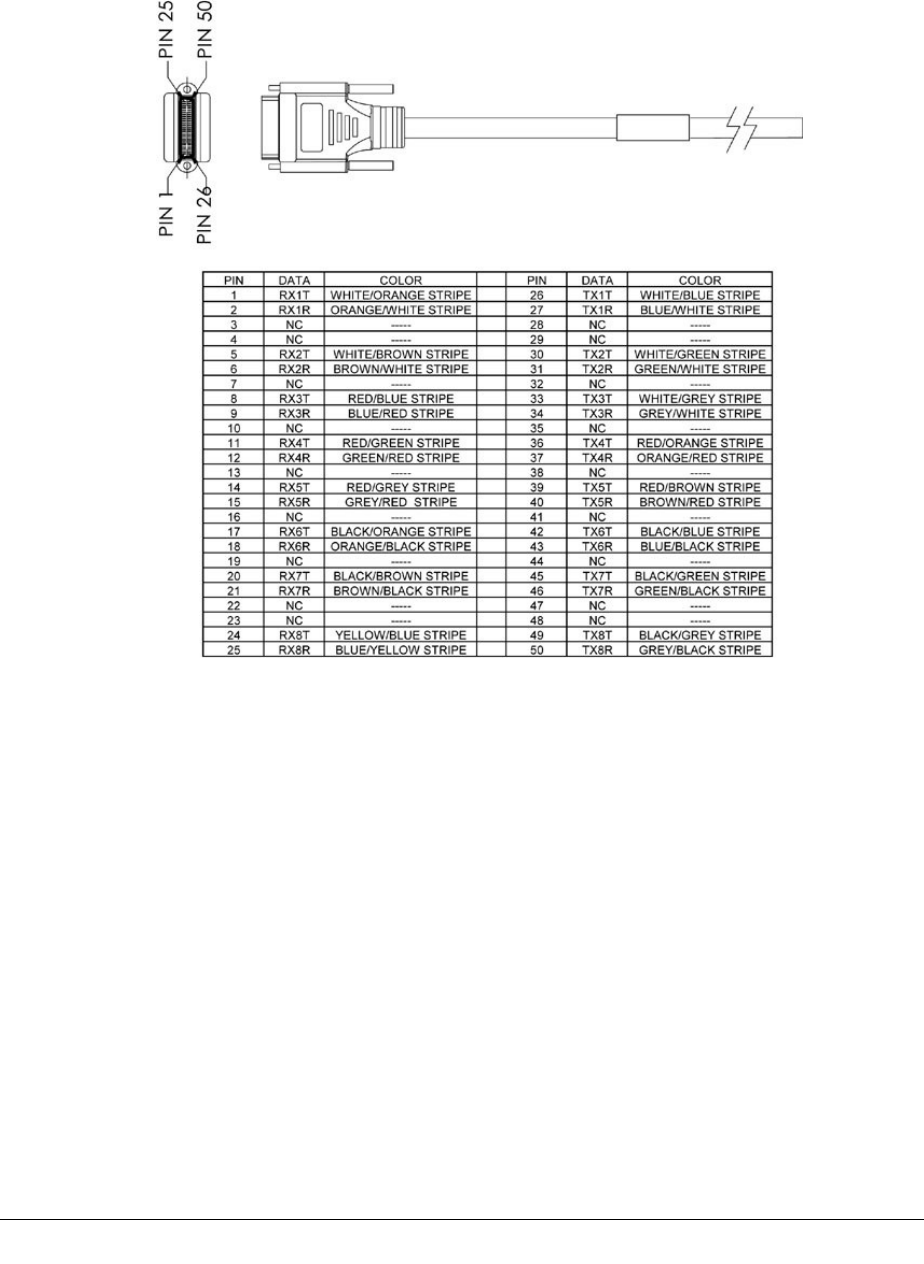
ECLIPSE INSTALLATION MANUAL
Each cable supports up to 8 tribs. Two cables are required per DAC if more than
8xE1/DS1 tribs are to be connected.
Figure 3-3. DAC 16xV2 Free End Trib Cable
RX indicates data into the DAC 16xV2 (DAC Rx).
TX indicates data out from the DAC 16xV2 (DAC Tx).
DAC 16xV2 HDR-E50 To BNC Cable Assembly
The HDR to BNC 75 ohm cable is available in lengths of 2.3m or 5.3m.
Each cable supports up to 8 tribs. Two cables are required per DAC if more than
8xE1/DS1 tribs are to be connected.
260-668066-004 AUGUST 2013 87
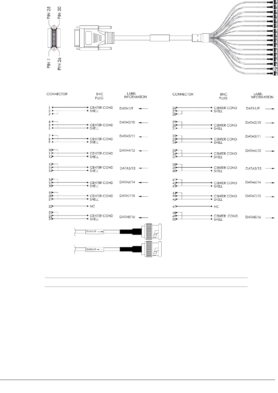
VOLUME III, CHAPTER 3, INU AND INUE INSTALLATION
Figure 3-4. DAC 16xV2 BNC Trib Cable Assembly
Figure 3-5. DAC 16xV2 BNC Trib Cable Connections
Arrow towards BNC indicates data out (DAC Tx).
Arrow away from BNC indicates data in (DAC Rx).
The 1/9 in the label indicates that it is for trib 1 if the cable assembly is used
with the trib 1-8 connector, or trib 9 if used with the trib 9-16 connector.
This also applies for 2/10, 3/11, etc. up to 8/16.
DAC 16xV2 HDR-E50 To RJ-45 Cable Assembly
The HDR to RJ-45 cable is available in lengths of 2m or 5m. Impedance is nom-
inally 120 ohms.
This cable (straight cable) is intended for connection to RJ-45 patch panels, which
have a built-in crossover function.
88 AVIAT NETWORKS
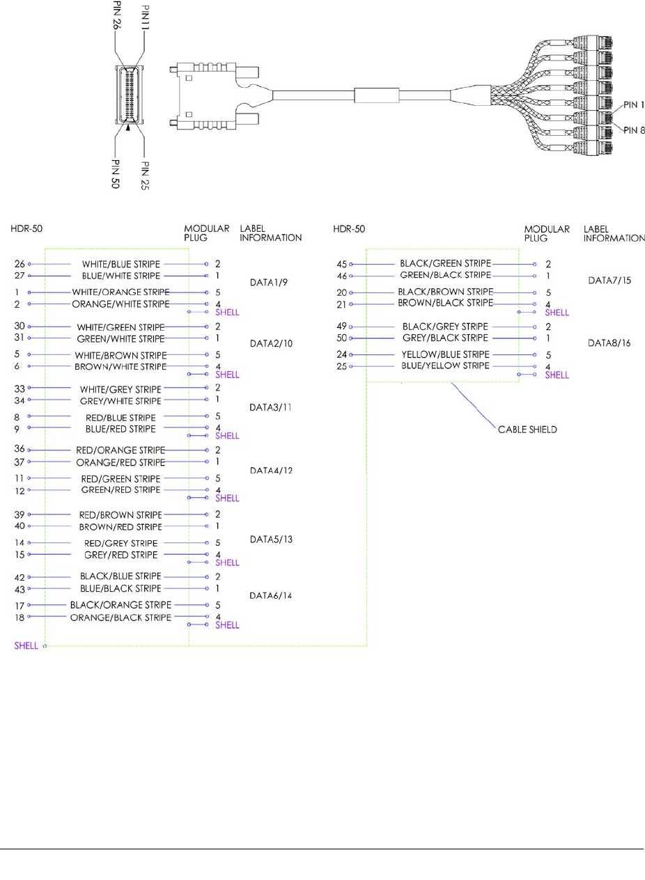
ECLIPSE INSTALLATION MANUAL
Each cable supports up to 8 tribs. Two cables are required per DAC if more than
8xE1/DS1 tribs are to be connected.
Figure 3-6. DAC 16xV2 RJ-45 Trib Cable
Figure 3-7. DAC 16xV2 RJ-45 Trib Cable Connections
DAC 16xV2 HDR-E50 To Free End Y-Cable Assembly
This cable is for use with DAC 16xV2 1+1 protected operation. It is available in
lengths of 3.5m, 15.5m or 5m. Impedance is nominally 120 ohms.
The 24 AWG wire is intended for use with wire-wrap or insulation displacement ter-
mination blocks.
260-668066-004 AUGUST 2013 89
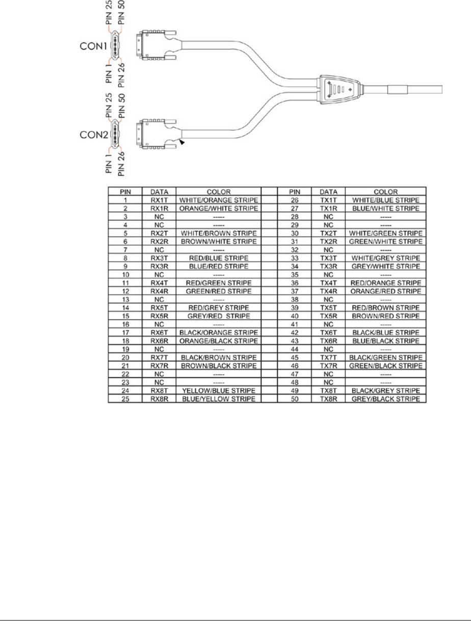
VOLUME III, CHAPTER 3, INU AND INUE INSTALLATION
Each cable supports up to 8 tribs. Two cables are required per DAC if more than
8xE1/DS1 tribs are to be connected.
Figure 3-8. DAC 16xV2 Free End Y-Cable
RX indicates data into the DAC 16xV2 (DAC Rx).
TX indicates data out from the DAC 16xV2 (DAC Tx).
DAC 16xV2 HDR-E50 To BNC Y-Cable Assembly
This cable is for use with DAC 16xV2 1+1 protected operation. It is available in
lengths of 3.5m, 15.5m or 5m. Impedance is nominally 75 ohms. Each cable sup-
ports up to 8 tribs. Two cables are required per DAC if more than 8xE1/DS1 tribs are
to be connected.
90 AVIAT NETWORKS
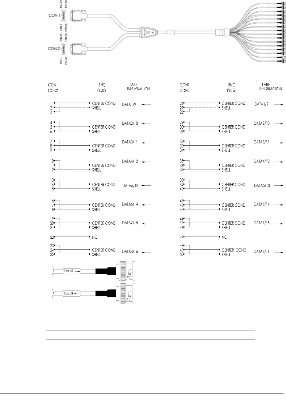
ECLIPSE INSTALLATION MANUAL
Figure 3-9. DAC 16xV2 Trib BNC Y-Cable
Figure 3-10. DAC 16xV2 Trib BNC Y-Cable Connections
Arrow towards BNC indicates data out (DAC Tx).
Arrow away from BNC indicates data in (DAC Rx).
The 1/9 in the label indicates that it is for trib 1 if the cable assembly is used
with the trib 1-8 connector, or trib 9 if used with the trib 9-16 connector.
This also applies for 2/10, 3/11, etc. up to 8/16.
260-668066-004 AUGUST 2013 91
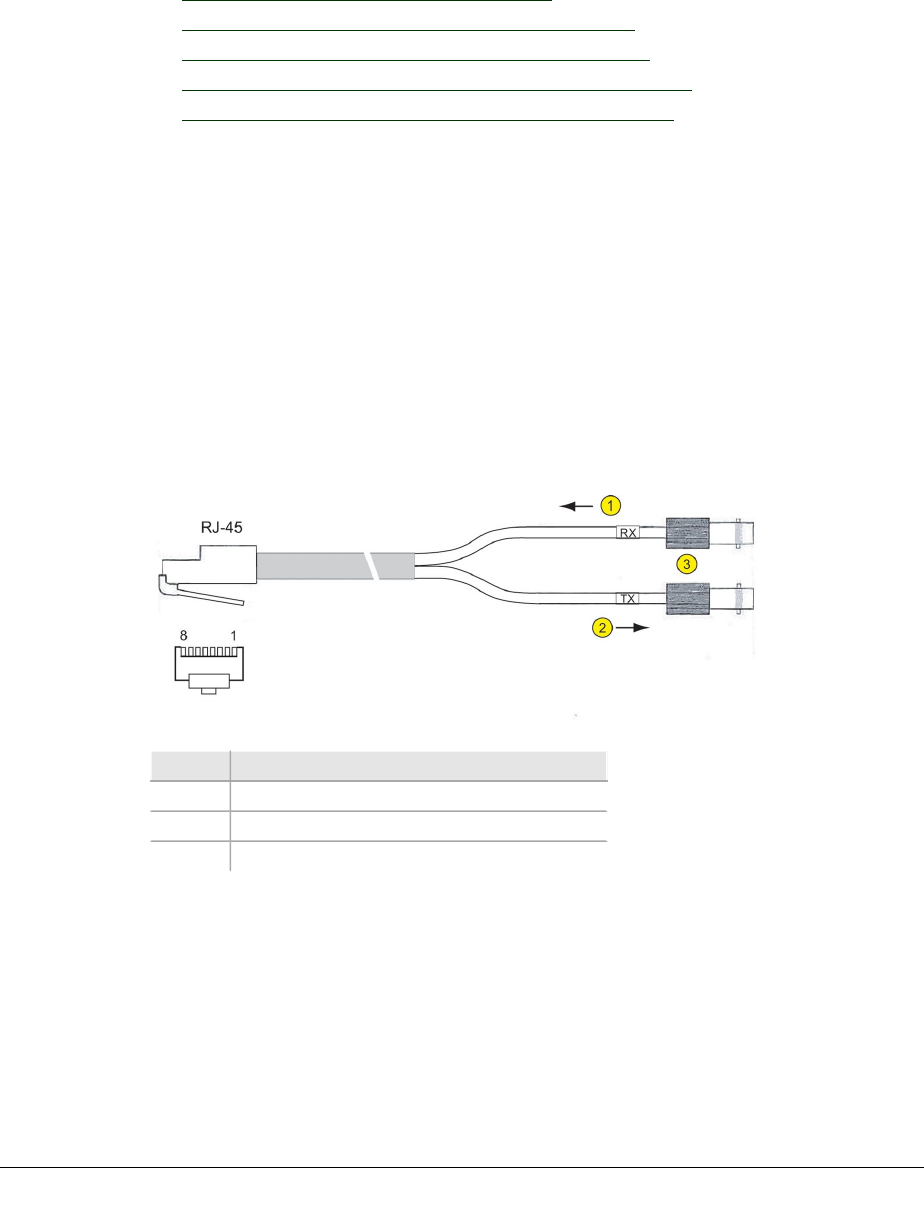
VOLUME III, CHAPTER 3, INU AND INUE INSTALLATION
DAC 4x Cable and Connector Data
Refer to:
lDAC 4x BNC Cable Assembly on page 92
lDAC 4x RJ-45 to RJ-45 Straight Cable on page 92
lDAC 4x RJ-45 to RJ-45 Crossover Cable on page 93
lDAC 4x RJ-45 to Wire Wrap Cable Assembly on page 93
lDAC 4x RJ-45 Connector Pin Assignments on page 94
DAC 4x BNC Cable Assembly
The assembly is provided as a kit of three cables. Each kit provides:
lOne RJ-45 to 2 x BNC female, 0.5m long.
lTwo BNC to BNC male extension cables, 2m or 5m long.
lOne kit is labeled as a 2.5m cable kit, the other as 5.5m.
Each supports one trib. Four are required if all four ports of the DAC 4x are to be con-
nected.
At the RJ-45 plug RX connects to pins 1 and 2, and TX connects to pins 4 & 5. The
pin-numbered RJ-45 plug is pictured with its cable exiting to the rear.
Figure 3-11. DAC 4x RJ-45 to BNC Cable
Item Description
1RX indicates Data In to the DAC.
2TX indicates Data Out from the DAC.
375 ohm BNC female connectors.
DAC 4x RJ-45 to RJ-45 Straight Cable
Connectors at both ends of the cable are wired pin-for-pin as shown in the figure
below. It provides a balanced 120 ohm connection.
Each cable supports one trib. Four cables are required if all four ports of the DAC 4x
are to be connected.
Straight cable assemblies are used when connecting to RJ-45 patch panels, which
have a built-in crossover function.
92 AVIAT NETWORKS

ECLIPSE INSTALLATION MANUAL
For Connection Function, receive specifies data in to the DAC; transmit is data out
from the DAC.
Table 3-5. DAC 4x RJ-45 to RJ-45 Straight Cable Connections
RJ-45 Pin-to-Pin Connections Connection Function
1 1 Receive Ring
2 2 Receive Tip
3 3 Optional Ground
4 4 Transmit Ring
5 5 Transmit Tip
6 6 Optional Ground
7 7 Ground
8 8 Ground
DAC 4x RJ-45 to RJ-45 Crossover Cable
Connectors are wired such that Receive Ring and Tip at one end connect to Transmit
Ring and Tip respectively, at the other. Pins 3, 6, 7, 8 remain the same. It provides a
balanced 120 ohm connection.
Each cable supports one trib. Four cables are required if all four ports of the DAC 4x
are to be connected.
Crossover cable assemblies are used to interconnect one DAC RJ-45 port to another.
For Connection Function, receive specifies data in to the DAC; transmit is data out
from the DAC.
Table 3-6. DAC 4x RJ-45 to RJ-45 Crossover Cable Assembly
Connection
Function
Pin-to-pin
Connections
Connection
Function
Receive Ring 14Transmit Ring
Receive Tip 25Transmit Tip
Optional Ground 33Optional Ground
Transmit Ring 41Receive Ring
Transmit Tip 52Receive Tip
Optional Ground 66Optional Ground
Ground 77Ground
Ground 88Ground
DAC 4x RJ-45 to Wire Wrap Cable Assembly
The assemblies are available with cable lengths of 2m, 5m or 7.5m. It provides a
balanced 120 ohm connection.
The wire is designed for use with wire wrap or insulation displacement termination
blocks.
260-668066-004 AUGUST 2013 93
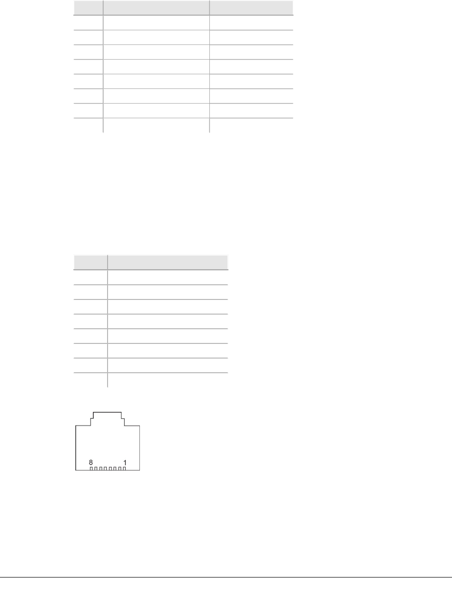
VOLUME III, CHAPTER 3, INU AND INUE INSTALLATION
Each cable supports one trib. Four cables are required if all four ports of the DAC 4x
are to be connected.
Receive specifies data in to the DAC; Transmit is data out from the DAC.
Table 3-7. DAC 4x Wire Wrap Cable Data
Pin Function Wire Color
1Receive Ring White / Orange
2Receive Tip Orange / White
3Optional Ground White / Green
4Transmit Ring Blue / White
5Transmit Tip White / Blue
6Optional ground Green / White
7Ground White / Brown
9Ground Brown / White
DAC 4x RJ-45 Connector Pin Assignments
This table shows the pin assignments for each front panel RJ-45 trib connector. Refer
to the figure below for connector pin numbering.
Receive refers to an input and specifies from the user.
Transmit refers to an output and specifies towards the user.
Table 3-8. DAC 4x RJ-45 Trib Connector Pin Assignments
Pin Function
1Receive Ring
2Receive Tip
3* Optional Ground
4Transmit Ring
5Transmit Tip
6* Optional Ground
7Ground
8Ground
Figure 3-12. RJ-45 Front Panel Connector (face view)
DAC GE3 Ethernet RJ-45 Cables
The table below list the RJ-45 Ethernet cable options for DAC GE3. One cable
required per port.
94 AVIAT NETWORKS

ECLIPSE INSTALLATION MANUAL
Table 3-9. RJ-45 Ethernet Cable Options
Description Part Number
Ethernet Cable, RJ45 to RJ45, 2 m 037-579124-001
Ethernet Cable, RJ45 to RJ45, 5 m 037-579125-001
Ethernet Cable, RJ45 to RJ45, 15 m 037-579126-001
The cables are industry-standard straight (Mdi) Ethernet RJ-45 to RJ-45.
DAC Optical Cable and Connector Data
The following table lists the cable and attenuator options for DAC 155oM, DAC
1x/2x155o, and for the optical SFPs available for DAC GE3.
Table 3-10. Optical Cables and Attenuators
Description Con
nec
tors
Mode Application Part number
SIMPLEX 0.5 M SM LC
TO LC
LC Single 1310 nM DAC GE3, DAC 155oM 037-579272-001
SIMPLEX 3M SM LC TO
LC
LC Single 1310 nM DAC GE3, DAC 155oM 037-579131-001
SIMPLEX 5M SM LC TO
LC
LC Single 1310 nM DAC GE3, DAC 155oM 037-579132-001
SIMPLEX 10M SM LC
TO LC
LC Single 1310 nM DAC GE3, DAC 155oM 037-579133-001
SIMPLEX 3M SM LC TO
FC
LC,
FC
Single 1310 nM DAC GE3, DAC 155oM 037-579134-001
SIMPLEX 5M SM LC TO
SC
LC,
SC
Single 1310 nM DAC GE3, DAC 155oM 037-579138-001
SPLITTER 2M LC-LC TO
SC
LC,
SC
Single 1310 nM DAC GE3, DAC 155oM 037-579142-001
SPLITTER 2M LC-LC TO
LC
LC Single 1310 nM DAC GE3, DAC 155oM 037-579143-001
ATTENUATOR 3M, LC,
10DB
LC Single 1310 nM DAC GE3, DAC 155oM 037-579155-001
ATTENUATOR 5M, LC,
10DB
LC Single 1310 nM DAC GE3, DAC 155oM 037-579156-001
SIMPLEX 2M SM LC TO
SC
LC,
SC
Single 1310 nM DAC GE3, DAC 155oM 037-579179-001
SIMPLEX 5M, SM SC-FC SC,
FC
Single 1310 nM DAC 1/2x155o 037-579191-001
SIMPLEX 3M, SM SC-SC SC Single 1310 nM DAC 1/2x155o 037-579194-001
SIMPLEX 5M, SM SC-SC SC Single 1310 nM DAC 1/2x155o 037-579194-005
SPLITTER 2M SC-SC TO
SC
SC Single 1310 nM DAC 1/2x155o 037-579198-001
SPLITTER 4M SC-SC TO
LC
SC,
LC
Single 1310 nM DAC 1/2x155o 037-579200-001
260-668066-004 AUGUST 2013 95

VOLUME III, CHAPTER 3, INU AND INUE INSTALLATION
SPLITTER 4M SC-SC TO
ST
SC,
ST
Single 1310 nM DAC 1/2x155o 037-579201-001
ATTENUATOR 3M, SC,
10DB
SC Single 1310 nM DAC 1/2x155o 037-579209-001
ATTENUATOR 5M, SC,
10DB
SC Single 1310 nM DAC 1/2x155o 037-579210-001
SIMPLEX 3M MM LC TO
LC
LC Multi 850 nM DAC 155oM 037-579431-001
SIMPLEX 10M MM LC
TO LC
LC Multi 850 nM DAC 155oM 037-579432-001
SIMPLEX 5M MM LC TO
SC
LC,
SC
Multi 850 nM DAC 155oM 037-579434-001
SIMPLEX 3M MM LC TO
FC
LC,
FC
Multi 850 nM DAC 155oM 037-579440-001
SPLITTER 2M MM SC
TO LC/LC
LC,
SC
Multi 850 nM DAC 155oM 037-579390-001
Single-mode (1310 nm) cables are available for LC to LC connections.
Single-mode and multi-mode (850 nm) cables are available for LC to SC connections.
Y-cable assemblies for protected DAC 155oM operation are available for single-mode
LC to LC, and for single-mode or multi-mode LC to SC connections.
LC to LC Connections - non-protected operation
Two cables required per connection.
Single-mode, part no. 037-579131-001: Simplex, single-mode, LC TO LC 3M (9 ft)
Single-mode, part no. 037-579132-001: Simplex, single-mode, LC TO LC 5M (16 ft)
LC to LC Connections - protected operation
lTwo Y-cable assemblies required per connection.
lSingle-mode, part no. 037-579143-001: Y-cable, single-mode, LC to LC, 2m (6
ft) splitter/combiner
lSingle-mode, part no. 037-579147-001: Y-cable, single-mode, LC to LC, 4m
(13ft) splitter/combiner
LC to SC Connections - non-protected operation
lTwo cables required per connection.
lSingle-mode cable part no. 037-579137-001: Simplex, single-mode, LC to SC
3m (9 ft)
lMulti-mode cable part no. 037-579180-001: Simplex, multi-mode, LC to SC
2m (6 ft)
96 AVIAT NETWORKS

ECLIPSE INSTALLATION MANUAL
LC to SC Connections - protected operation
lTwo Y-cable assemblies required per connection.
lSingle-mode, part no. 037-579142-001: Y-cable, single-mode, LC to SC, 2m (6
ft) splitter/combiner
lMulti-mode, part no. 037-579390-001: Y-cable, multi-mode, LC to SC, 2m (6
ft) splitter/combiner
Other cable options are availabl e for LC connection to FC or
ST. Contact Aviat Networks or your supplier for details.
DAC 155eM Cables
The following cables are for use with the DAC 155eM (electrical SFP):
Part number Description
037-579462-003 CABLE, M1.0/2.3 TO M1.6/5.6, 75 OHM STRANDED 3m
037-579462-005 CABLE, M1.0/2.3 TO M1.6/5.6, 75 OHM STRANDED 5m
037-579462-010 CABLE, M1.0/2.3 TO M1.6/5.6, 75 OHM STRANDED 10m
037-579472-002 CABLE, M1.0/2.3 TO M1.0/2.3, 75 OHM STRANDED, 2M
037-579466-001 CABLE, M1.0/2.3 TO M1.0/2.3, 75 OHM STRANDED, 150mm
NMS Connectors and Cables
Data is included for:
lNMS 10/100Base-T Connector on page 97
lMaintenance V.24 Connector on page 98
NMS 10/100Base-T Connector
The NMS connector provides Ethernet access for Portal or ProVision. Pin assign-
ments represent industry-standard LAN cable assembly for a 10/100Base-T, RJ-45
connector. Different length ‘straight’ Ethernet cables are included as optional
accessories.
The Eclipse INU/INUe has a four-port 10/100Base-T NMS assembly. The Ethernet
port auto-resolves for straight and crossover cables (Mdi or MdiX). Either cable type
can be used.
The port connectivity and activity LED indications are not consistent across all
Eclipse products. The orange LED indicates connectivity (on for a valid connection)
and the green LED flashes to indicate traffic activity.
260-668066-004 AUGUST 2013 97
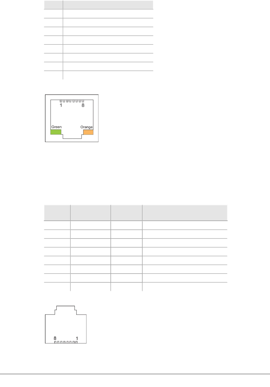
VOLUME III, CHAPTER 3, INU AND INUE INSTALLATION
Table 3-11. RJ-45 Ethernet NMS Connector Pin Assignments
Pin Function
1Ethernet transmit data +
2Ethernet transmit data -
3Ethernet receive data +
4Not used
5Not used
6Ethernet receive data -
7Not used
8Not used
Figure 3-13. RJ-45 Ethernet NMS Connector(s)
Maintenance V.24 Connector
The V.24 connector provides serial data access for Portal. One industry-standard RJ-
45 to DB-9 V.24 Maintenance Cable is included with every INU.
Table 3-12. RJ-45 V.24 Connector Pin Assignment
Pin Signal
Name
Direction Function
1 DSR/RI In Data Set Ready/Ring Indicator
2 CD In Carrier Detect
3 DTR Out Data Terminal Ready
4 GND System Ground
5 RXD In Receive Data
6 TXD Out Transmit Data
7 CTS In Clear to Send
8 RTS Out Request to Send
Figure 3-14. RJ-45 V.24 Portal Connector (face view)
98 AVIAT NETWORKS
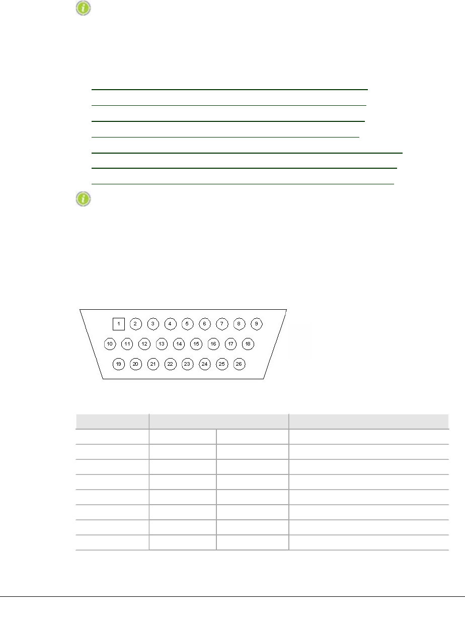
ECLIPSE INSTALLATION MANUAL
Auxiliary and Alarm Connectors and Cables
Data is included for AUX Plug-in auxiliary interfaces and cable-sets.
Alarm and Auxiliary cables should not terminate to equi pment
outside the shelter or building. Use approved surge sup-
pr ession equipment when connecting to un-protected external
inputs and outputs.
Refer to:
lAUX Data Cable: Async, HD26 to Wirewrap, 2m on page 99
lAUX Data Cable: Sync, HD26 to Wirewrap, 2m on page 100
lAUX Data Cable: Async, HD26 to 3 X DB9, 1m on page 101
lAUX Data Cable: Sync, HD26 to 3 X DB9, 1m on page 102
lAUX Data Cable: Async, AUX HD26 to AUX HD26, 1m on page 103
lAUX Data Cable: Sync, AUX HD26 to AUX HD26, 1m on page 104
lAUX Alarm I/O Cable: HD15 to Wirewrap, 2m or 5m on page 105
In this section, all connector front views are cabl e-connector
views.
AUX Data Cable: Async, HD26 to Wirewrap, 2m
Part No: 037-579114-00
Figure 3-15. AUX HD26, 2M, Async, Front View
Table 3-13. Pin Descriptions and Color Code for Part # 037-579114-00
Pin No. Function Wire Color Code
TIA/E1A-562 DCE Direction
1Output Green/Black
2Output Black/Green
3Aux RXD1 Output Black/Orange
4Output Brown/Black
5Aux TXD1 Input Orange/Black
6Input Black/Brown
7I/O Brown/White
260-668066-004 AUGUST 2013 99
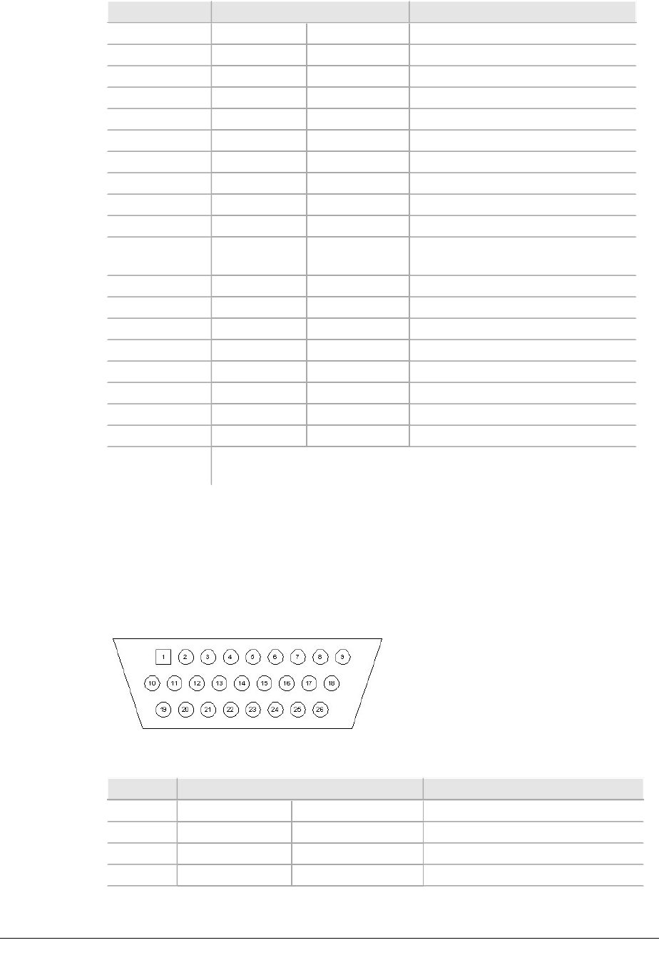
VOLUME III, CHAPTER 3, INU AND INUE INSTALLATION
Pin No. Function Wire Color Code
8I/O White/Brown
9GND Black/Blue
10 Output White/Gray
11 Output Gray/White
12 Aux RXD2 Output Red/Gray
13 Output Black/Gray
14 Aux TXD2 Input Gray/Red
15 Input Gray/Black
16 I/O Green/White
17 I/O White/Green
18 GND
(Shared)
Drain
19 Output Brown/Red
20 Output Red/Brown
21 Aux RD Output Blue/Yellow
22 Output Yellow/Blue
23 Aux TXD3 Input Red/Blue
24 Input Blue/Red
25 I/O Blue/White
26 I/O White/Blue
Wire Colors
Not Used:
Blue/Black, Green/Red, Red/Green, Red/Orange, Orange/Red,
White/Orange, Orange/White
AUX Data Cable: Sync, HD26 to Wirewrap, 2m
Part No: 037-579115-00
Figure 3-16. AUX HD26, 2M, Sync, Wirewrap, Front View
Table 3-14. Pin Descriptions and Color Code for Part # 037-579115-00
Pin No. Function Wire Color Code
TIA/E1A-422 DCE Direction
11AuxRXC+ Output Green/Black
21AuxRXC- Output Black/Green
31RXD- Output Black/Orange
100 AVIAT NETWORKS

ECLIPSE INSTALLATION MANUAL
Pin No. Function Wire Color Code
41RXD+ Output Orange/Black
51TXD+ Input Brown/Black
61TXD- Input Black/Brown
71AuxTXC+ I/O Brown/White
81AuxTXC- I/O White/Brown
9GND Black/Blue
10 2AuxRXC+ Output White/Gray
11 2AuxRXC- Output Gray/White
12 2RXD- Output Red/Gray
13 2RXD+ Output Gray/Red
14 2TXD+ Input Black/Gray
15 2TXD- Input Gray/Black
16 2AuxTXC+ I/O Green/White
17 2AuxTXC- I/O White/Green
18 GND (Shared) Drain
19 3AuxRXC+ Output Brown/Red
20 3AuxRXC- Output Red/Brown
21 3RXD- Output Blue/Yellow
22 3RXD+ Output Yellow/Blue
23 3TXD+ Input Red/Blue
24 3TXD- Input Blue/Red
25 3AuxTXC+ I/O Blue/White
26 3AuxTXC- I/O White/Blue
Wire
Colors
Not
Used:
Blue/Black, Red/Green, Green/Red, Red/Orange, Orange/Red,
White/Orange, Orange/White
AUX Data Cable: Async, HD26 to 3 X DB9, 1m
Part No: 037-579116-00
260-668066-004 AUGUST 2013 101
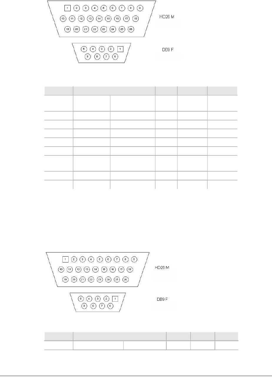
VOLUME III, CHAPTER 3, INU AND INUE INSTALLATION
Figure 3-17. AUX HD26 and 3 X DB9, 1M, Async: Front Views
Table 3-15. Pin Descriptions and Color Code for Part # 037-579116-00
AUX Function AUX 1 AUX 2 AUX 3
Pin No. TIA/E1A-
562
DCE Direction Pin No. Pin No. Pin No.
3AuxRXD1 Output 2
5AuxTXD1 Input 3
9GND 5
12 AuxRXD2 Output 2
14 AuxTXD2 Input 3
18 GND
(Shared)
5 5
21 AuxRXD3 Output 2
23 AuxTXD3 Input 3
AUX Data Cable: Sync, HD26 to 3 X DB9, 1m
Part No: 037-579117-001
Figure 3-18. AUX HD26 to 3 X DB9, 1m, Sync, Front Views
Table 3-16. Pin Descriptions for 037-579117-001
AUX Function AUX 1 AUX 2 AUX 3
Pin No. TIA/E1A-422 DCE Direction Pin No. Pin No. Pin No.
102 AVIAT NETWORKS

ECLIPSE INSTALLATION MANUAL
AUX Function AUX 1 AUX 2 AUX 3
11AuxRXC+ Output 1
21AuxRXC- Output 6
31RXD- Output 2
41RXD+ Output 7
51TXD+ Input 3
61TXD- Input 8
71AuxTXC+ I/O 4
81AUXTXC- I/O 9
9GND 5
10 2AuxRXC+ Output 1
11 2AuxRXC- Output 6
12 2RXD- Output 2
13 2RXD+ Output 7
14 2TXD+ Input 3
15 2TXD- Input 8
16 2AuxTXC+ I/O 4
17 2AUXTXC- I/O 9
18 GND (Shared) 5 5
19 3AuxRXC+ Output 1
20 3AuxRXC- Output 6
21 3RXD- Output 2
22 3RXD+ Output 7
23 3TXD+ Input 3
24 3TXD- Input 8
25 3AuxTXC+ I/O 4
26 3AUXTXC- I/O 9
AUX Data Cable: Async, AUX HD26 to AUX HD26, 1m
Part No: 037-579120-001
Figure 3-19. AUX TO AUX, HD26, 1M, ASYNC, Front View
260-668066-004 AUGUST 2013 103
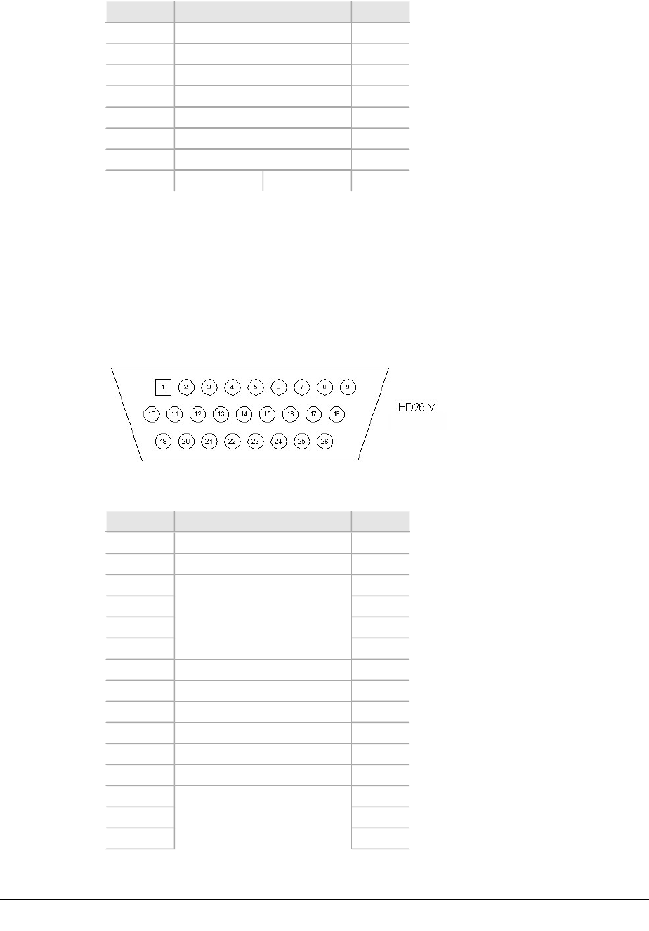
VOLUME III, CHAPTER 3, INU AND INUE INSTALLATION
Table 3-17. Pin Descriptions for 037-579120-001
AUX Function AUX
3AuxRXD1 AuxTXD1 5
5AuxTXD1 AuxRXD1 3
9Ground Ground 9
12 AuxRXD2 AuxTXD2 14
14 AuxTXD2 AuxRXD2 12
18 Ground Ground 18
21 AuxRXD3 AuxTXD3 23
23 AuxTXD3 AuxRXD3 21
AUX Data Cable: Sync, AUX HD26 to AUX HD26, 1m
Part No: 037-579121-001
Figure 3-20. AUX TO AUX, HD26, 1m, Sync, Front View
Table 3-18. Pin Descriptions for 037-579121-001
AUX Function AUX 1
11AuxRXC+ 1AuxTXC+ 7
21AuxRXC- 1AuxTXC- 8
31RXD- 1TXD- 6
41RXD+ 1TXD+ 5
51TXD+ 1RXD+ 4
61TXD- 1RXD- 3
71AuxTXC+ 1AuxRXC+ 1
81AUXTXC- 1AUXRXC- 2
9GND GND 9
10 2AuxRXC+ 2AuxTXC+ 16
11 2AuxRXC- 2AuxTXC- 17
12 2RXD- 2TXD- 15
13 2RXD+ 2TXD+ 14
14 2TXD+ 2RXD+ 13
15 2TXD- 2RXD- 12
104 AVIAT NETWORKS
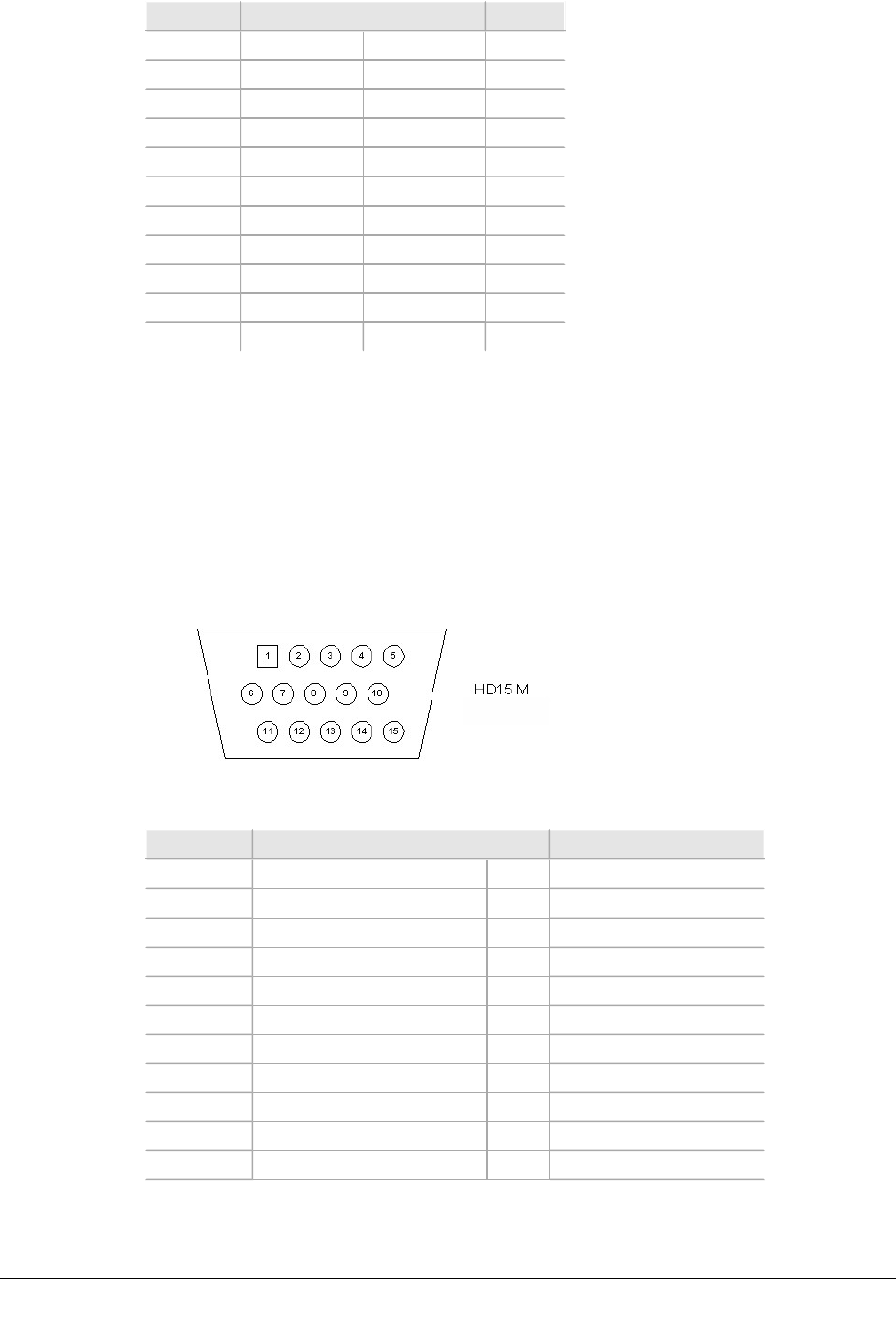
ECLIPSE INSTALLATION MANUAL
AUX Function AUX 1
16 2AuxTXC+ 2AuxRXC+ 10
17 2AUXTXC- 2AUXRXC- 11
18 GND GND 18
19 3AuxRXC+ 3AuxTXC+ 25
20 3AuxRXC- 3AuxRTXC- 26
21 3RXD- 3TXD- 24
22 3RXD+ 3TXD+ 23
23 3TXD+ 3RXD+ 22
24 3TXD- 3RXD- 21
25 3AuxTXC+ 3AuxRXC+ 19
26 3AuxTXC- 3AuxRXC- 20
AUX Alarm I/O Cable: HD15 to Wirewrap, 2m or 5m
Part No: 037-579112-001, 2m
Part No: 037-579113-001, 5m
Figure 3-21. ALARM I/O, HD15, 2M, WIREWRAP, Front View
Table 3-19. Pin Descriptions for 037-579112-001 and 037-579113-001
Pin No. Function Wire Color Code
1TTL Input 1 I Brown/White
2Relay 1 NC I/O White/Brown
3Relay 1 NO I/O White/gray
4Relay 2 Pole/TTL Input 5 I/O gray/White
5Relay 3 NC I/O Red/Blue
6Relay 3 NO I/O Blue/Red
7Relay 4 Pole/TTL Input 3 I/O Orange/Red
8Ground Drain
9TTL Input 2 I Red/Orange
10 Relay 1 Pole/TTL Input 6 I/O Red/Green
11 Relay 2 NC I/O Green/Red
260-668066-004 AUGUST 2013 105

VOLUME III, CHAPTER 3, INU AND INUE INSTALLATION
Pin No. Function Wire Color Code
12 Relay 2 NO I/O Orange/White
13 Relay 3 Pole/TTL Input 4 I/O White/Orange
14 Relay 4 NC I/O White/Green
15 Relay 4 NO I/O Green/White
Wire
Colors
Not Used:
White/Blue, Blue/White
The output relay is a 4 pole, double throw; it has four independent switch contact
sets, where the pole (common) connection on each set switches between NO (nor-
mally open) and NC (normally closed) contacts. Note that the relays may be con-
figured to be energized or de-energized on receipt of an alarm event.
lActive Condition De-energized requires an alarm event to release the relay.
lActive Condition Energized requires an alarm event to energize the relay.
106 AVIAT NETWORKS