Aviation Communications and Surveillance Systems MSS25 Multi Link Transponder User Manual FrontMatter
Aviation Communications and Surveillance Systems (ACSS), LLC. Multi Link Transponder FrontMatter
UserManual.wiki
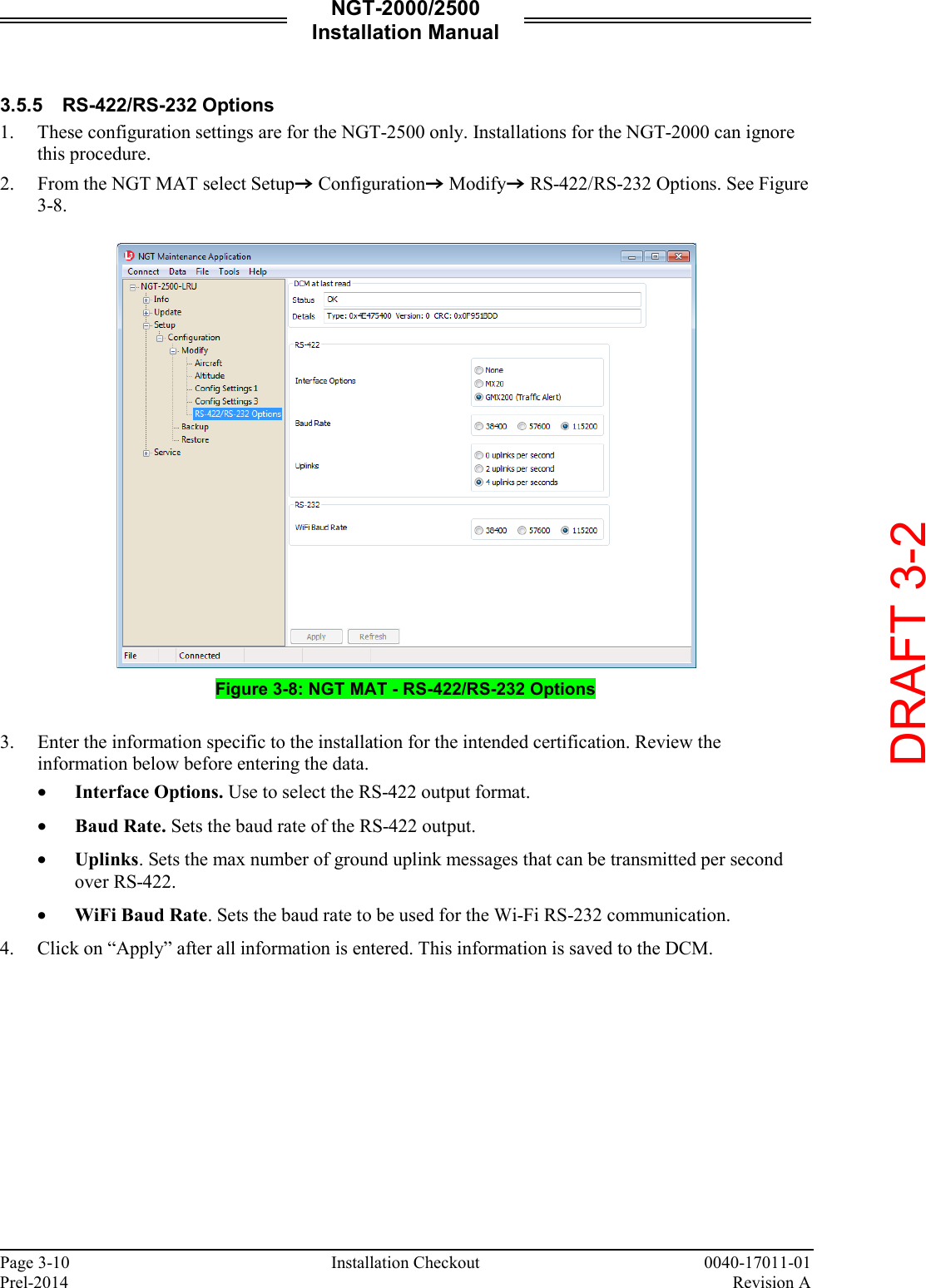
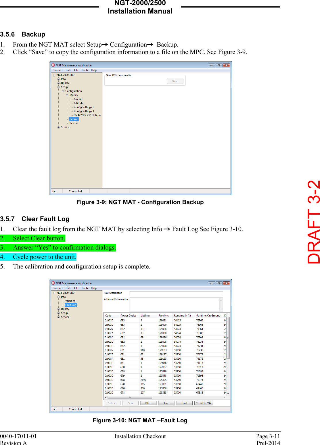
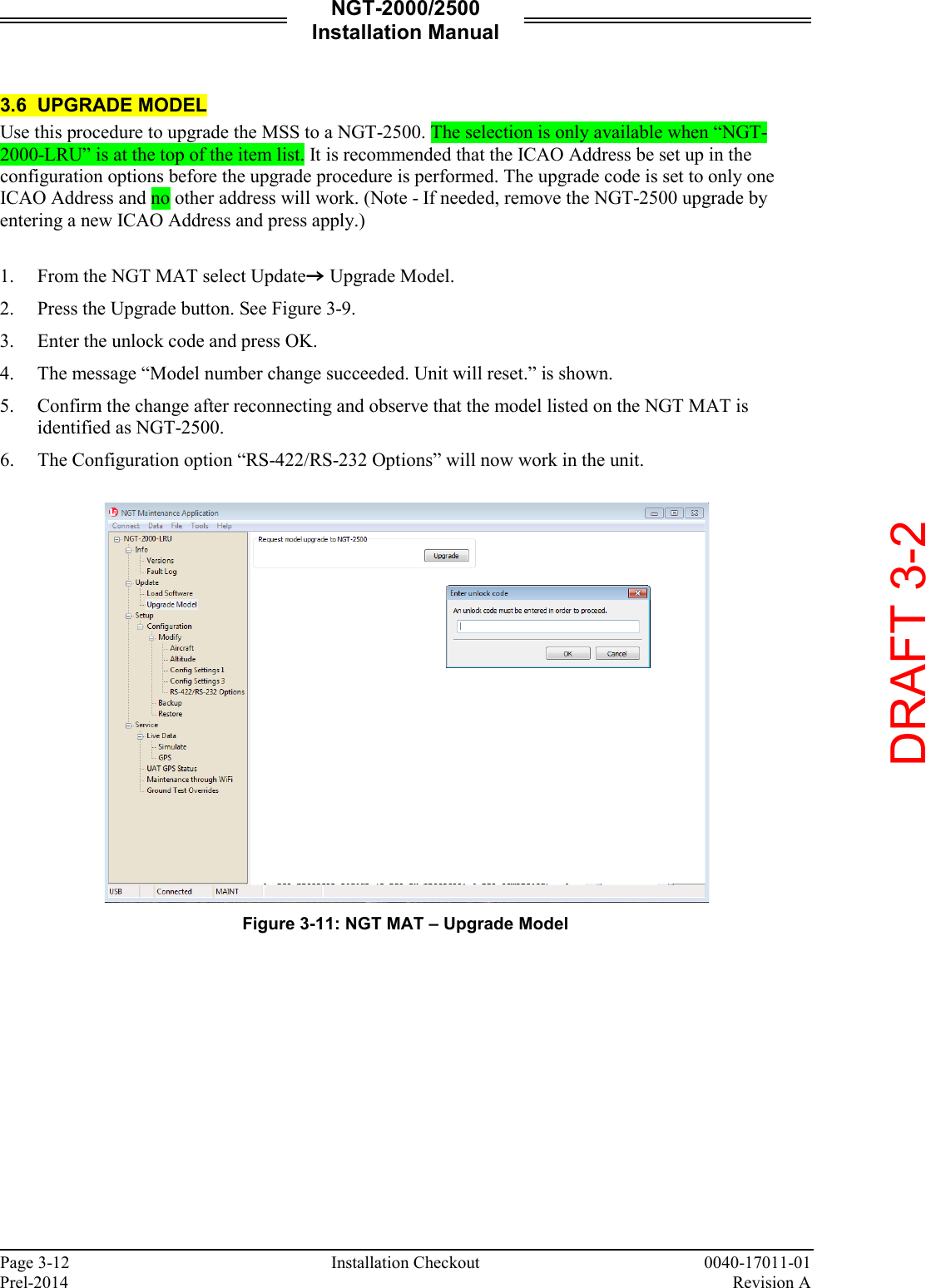
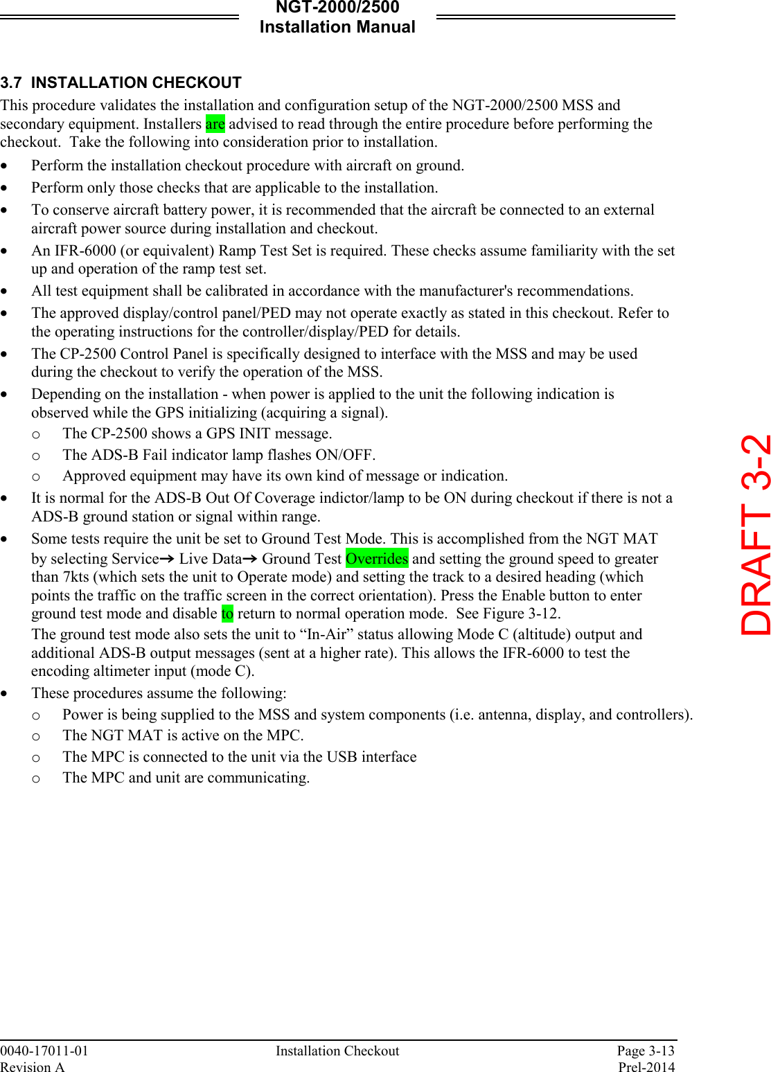
>
Aviation Communications and Surveillance Systems
>
MSS25 User Manual
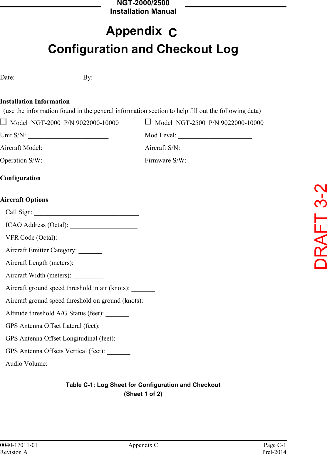
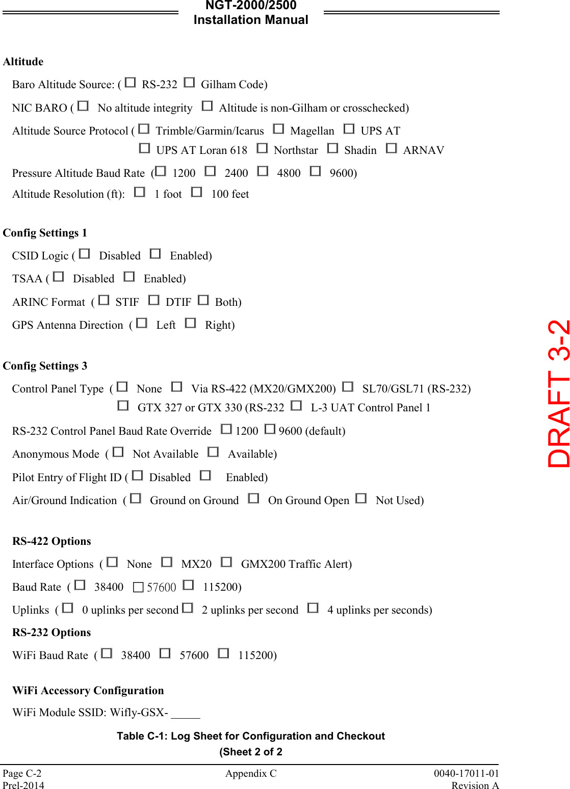
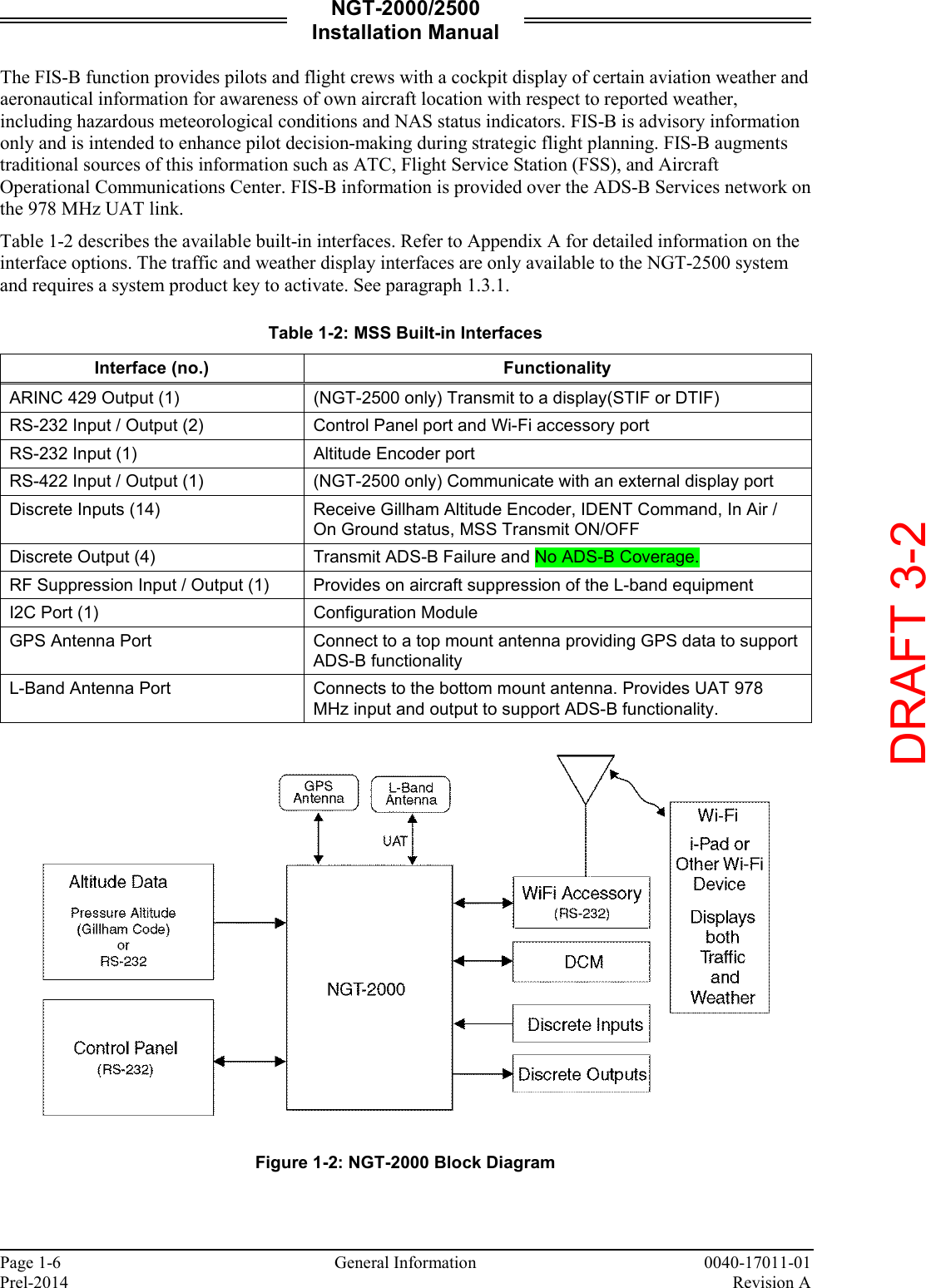
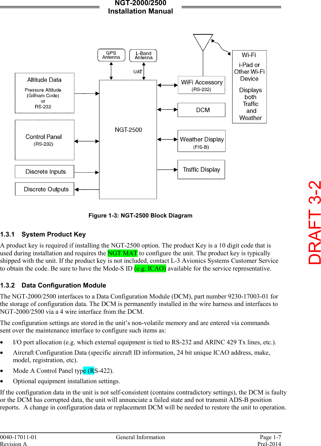
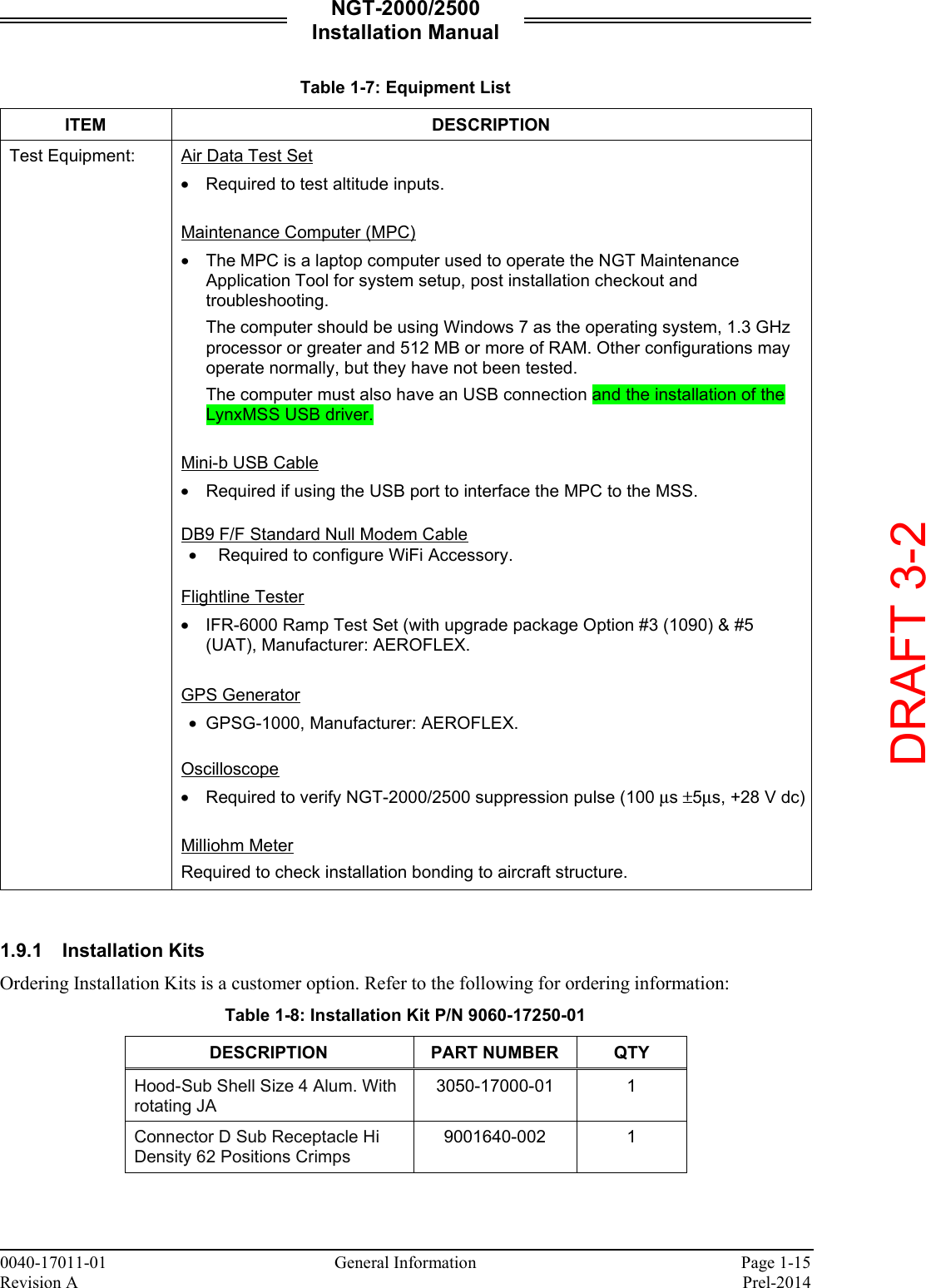
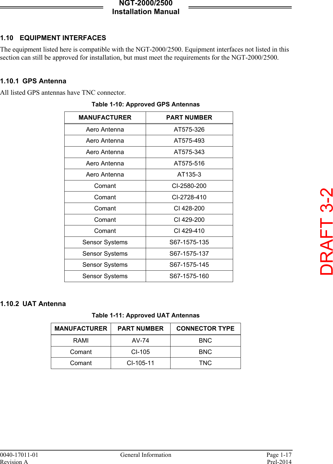
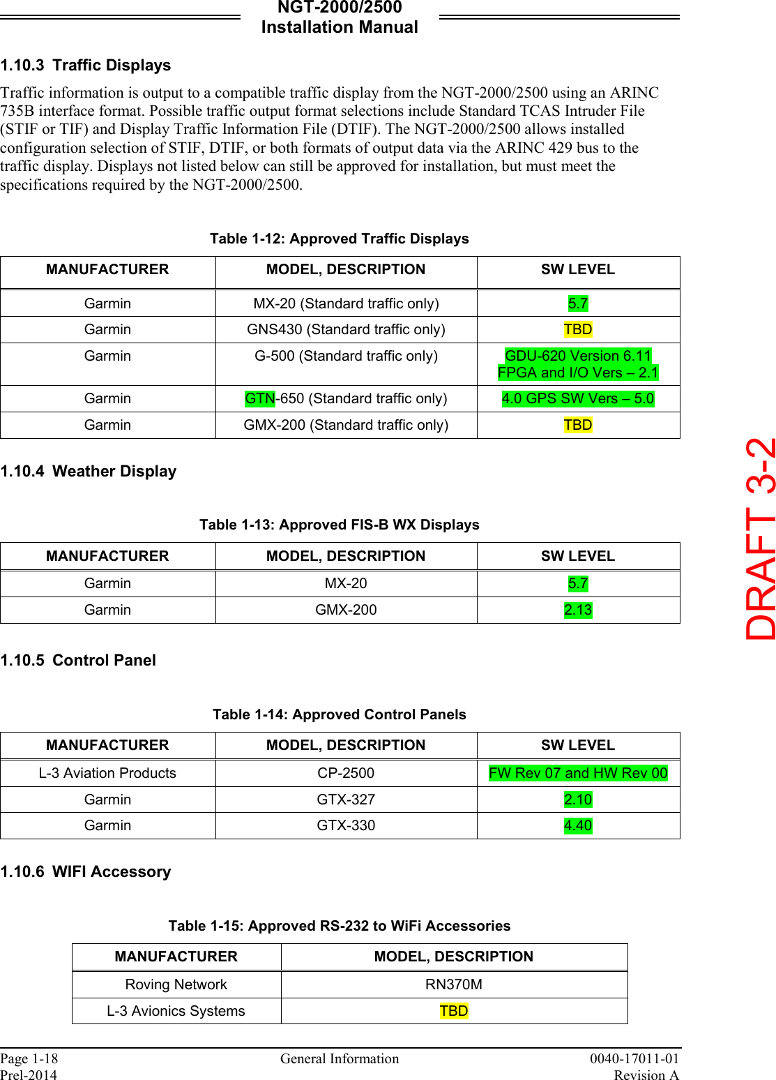
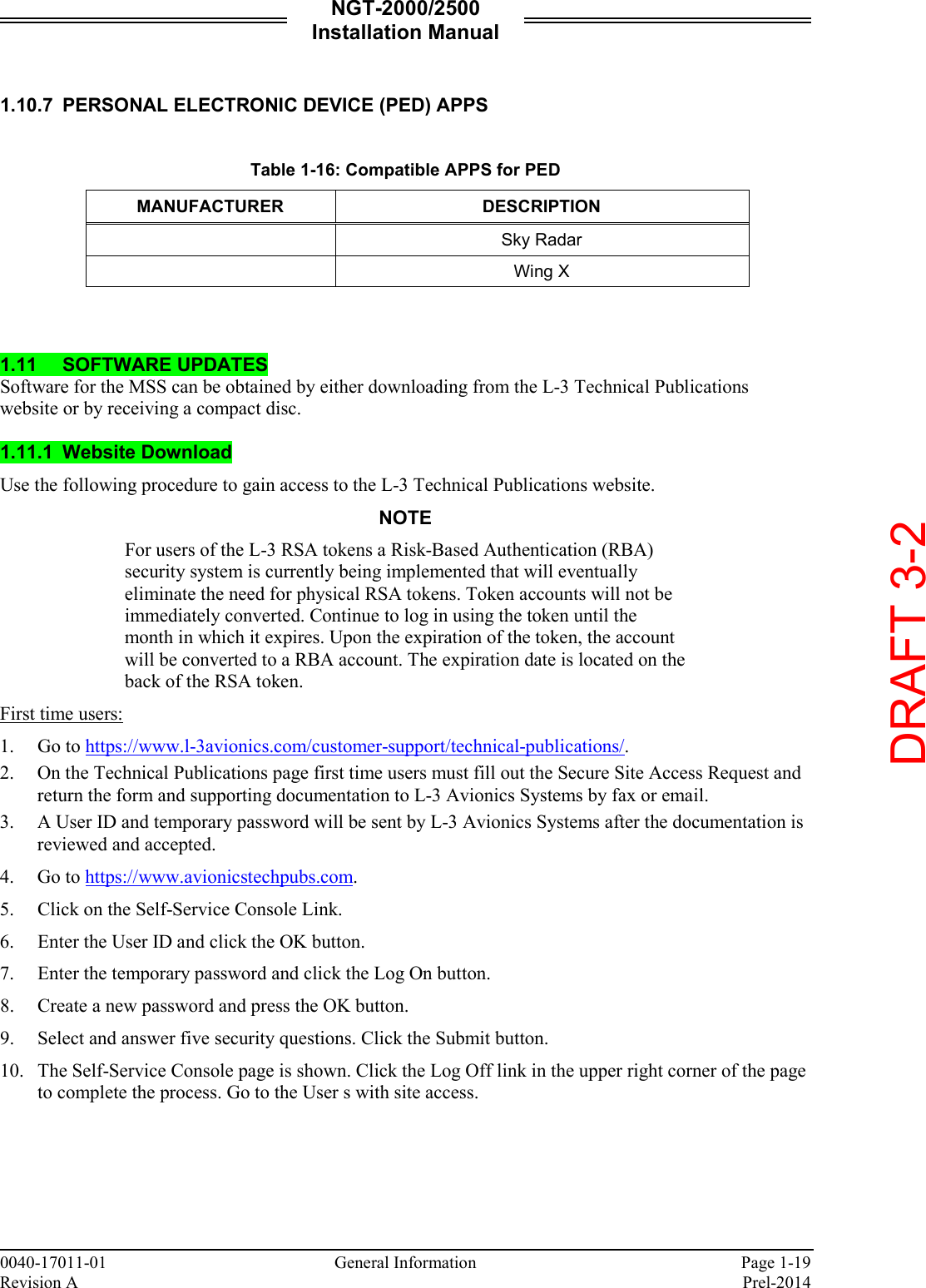
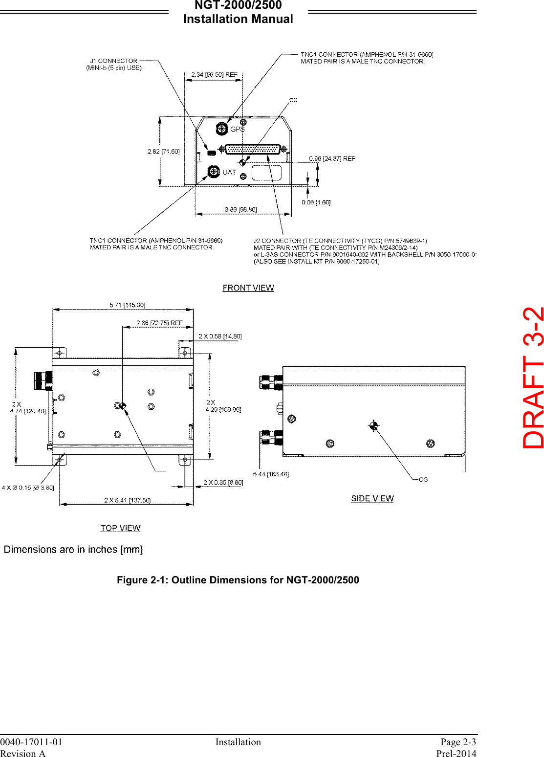
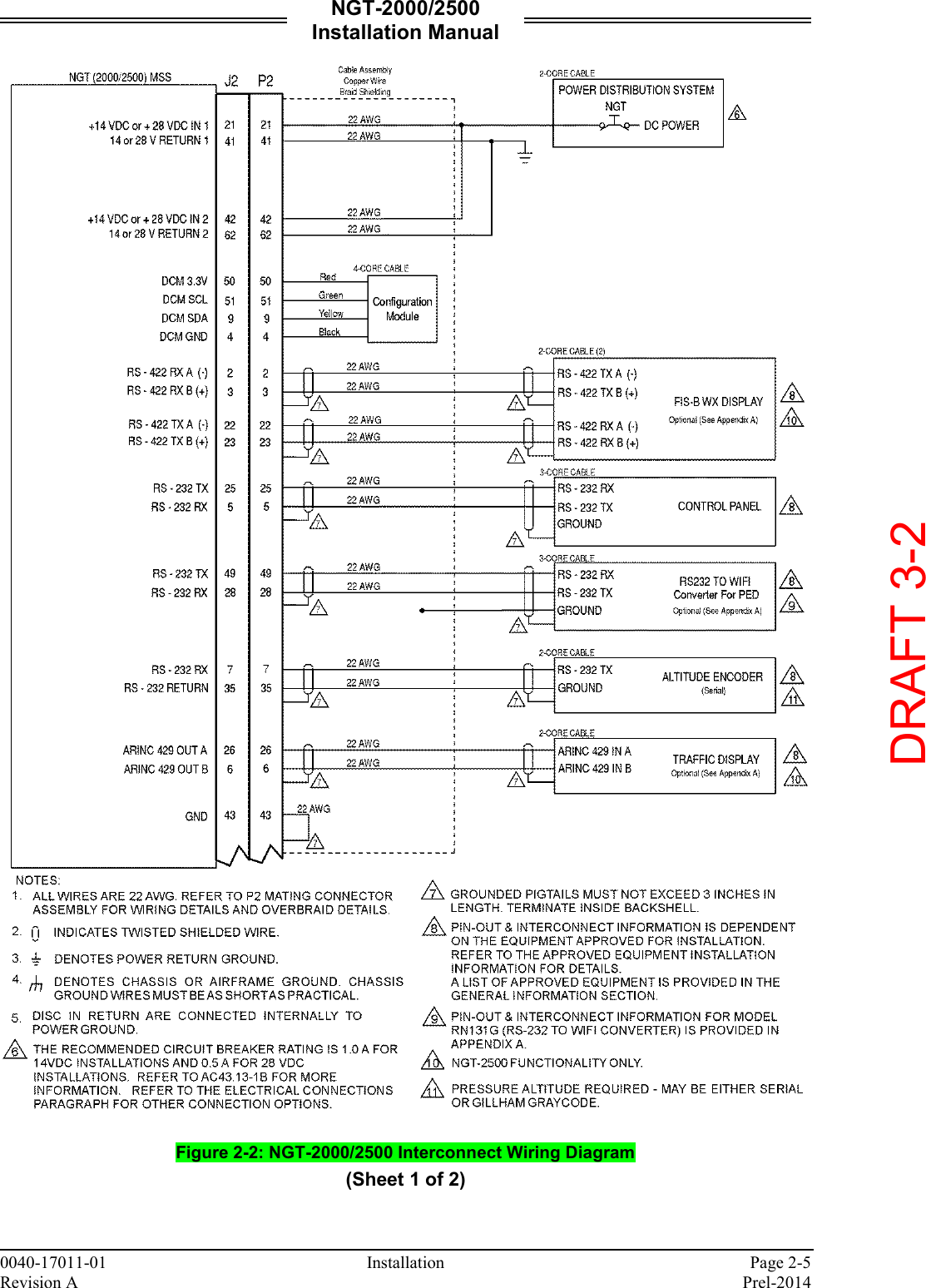
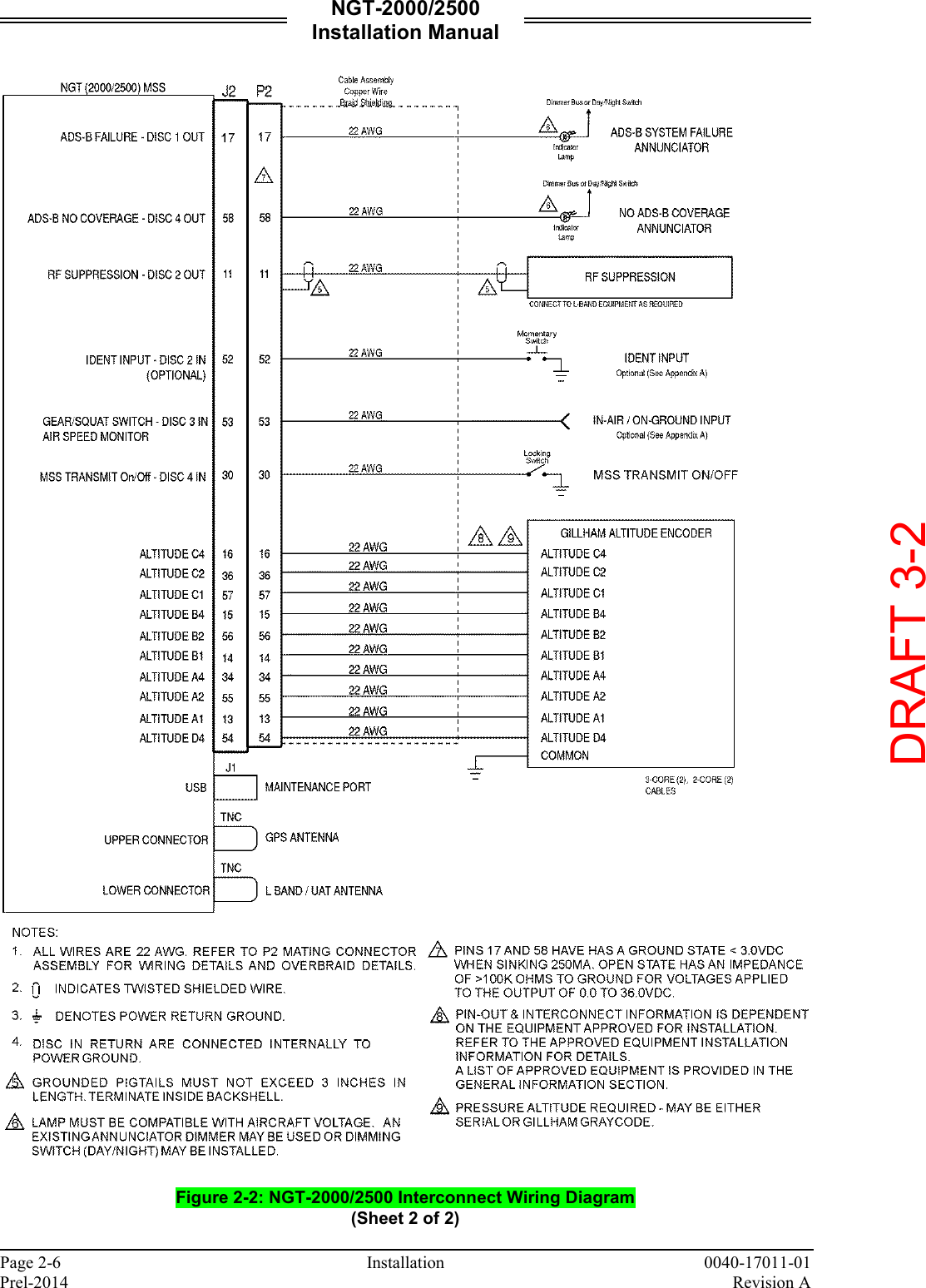
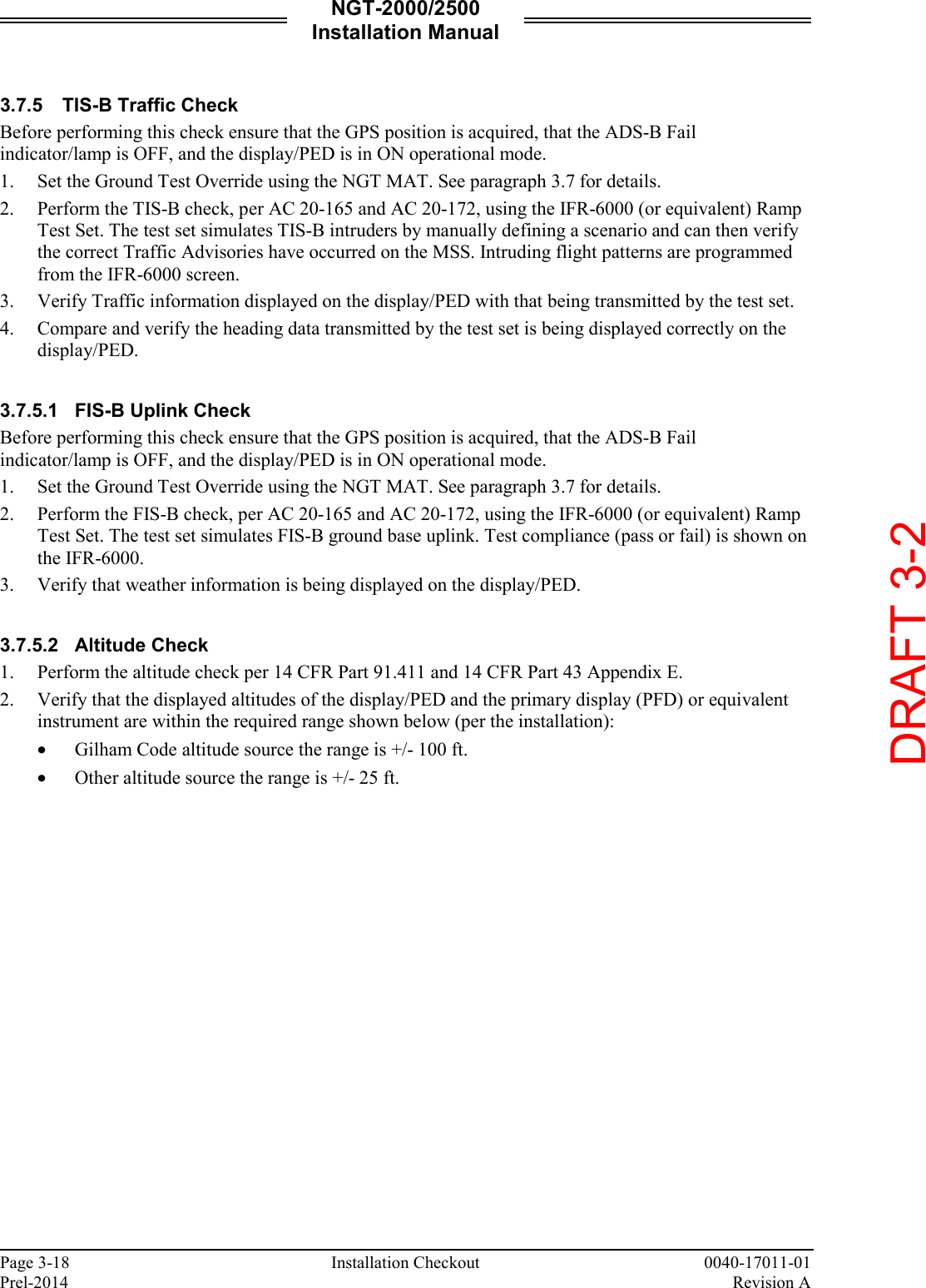
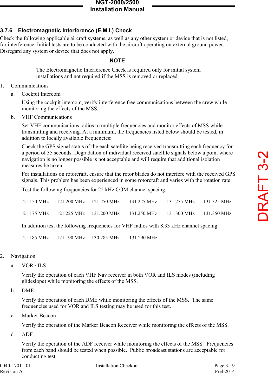
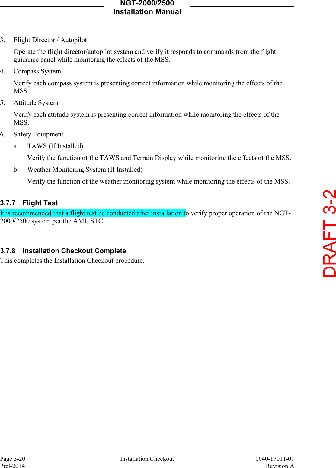
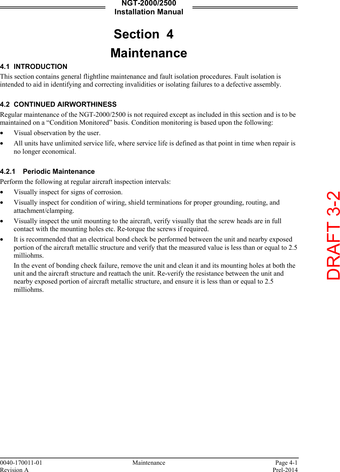
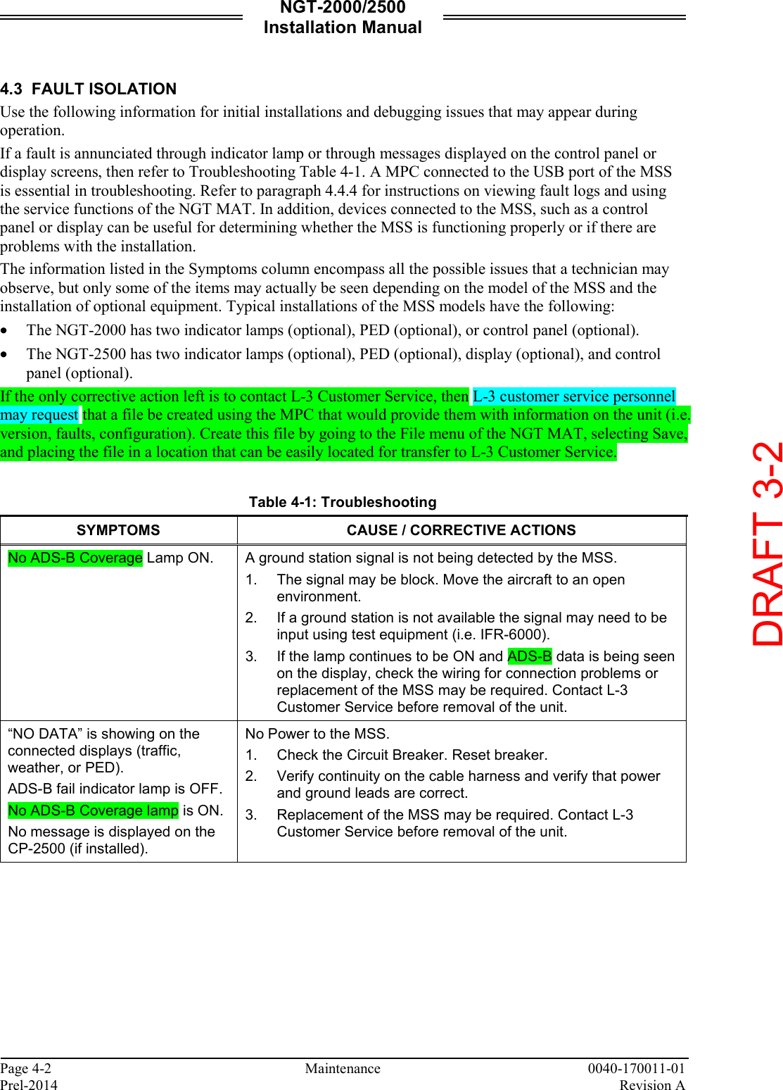
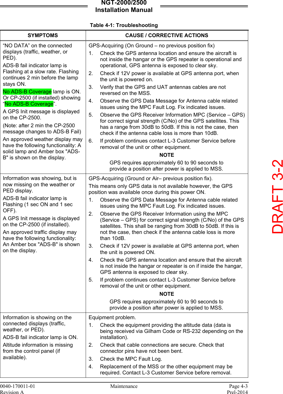
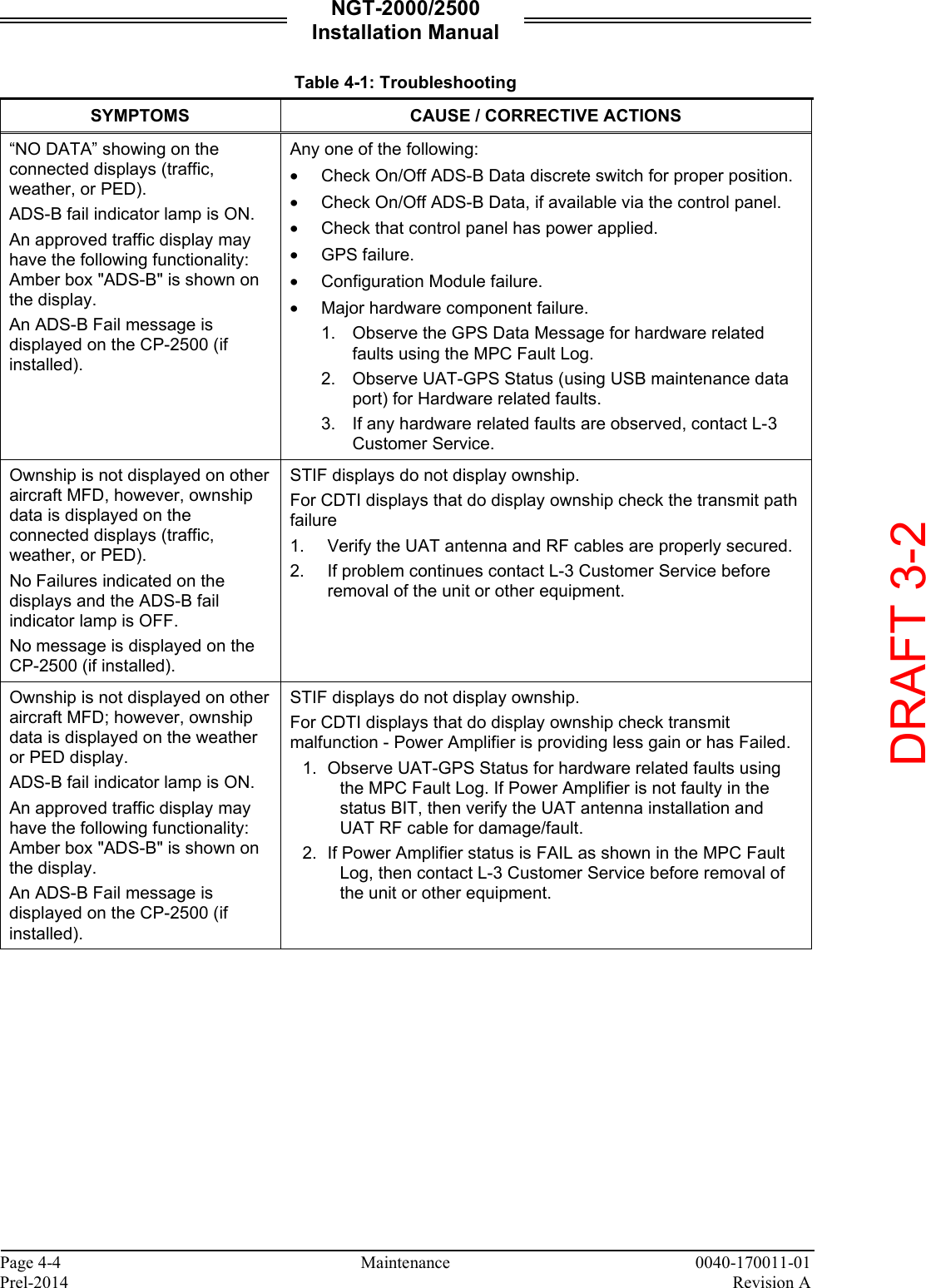
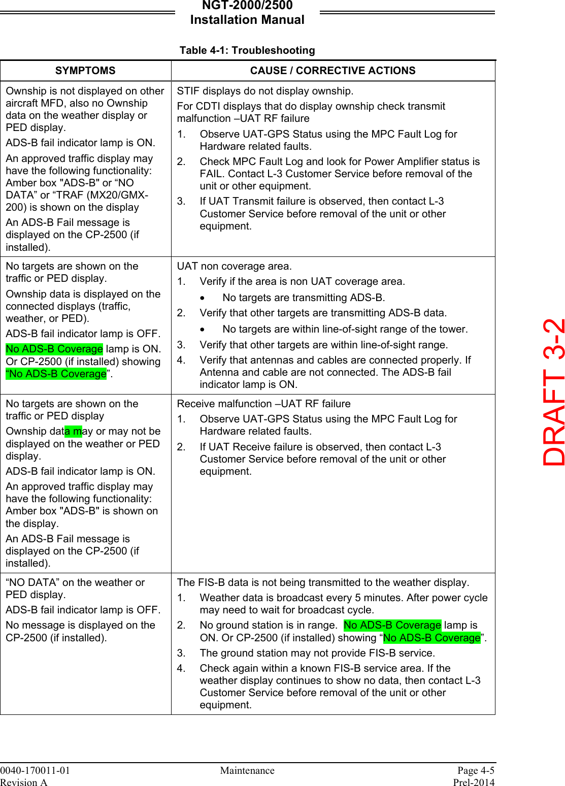
Installation Manual
Navigation menu
Upload a User Manual
Namespaces
Wiki Guide
HTML
PDF
Info
Views
User Manual
Discussion / Help
Navigation

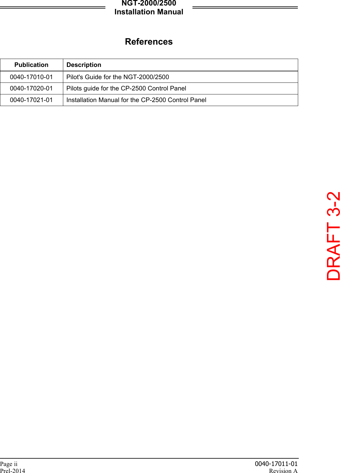
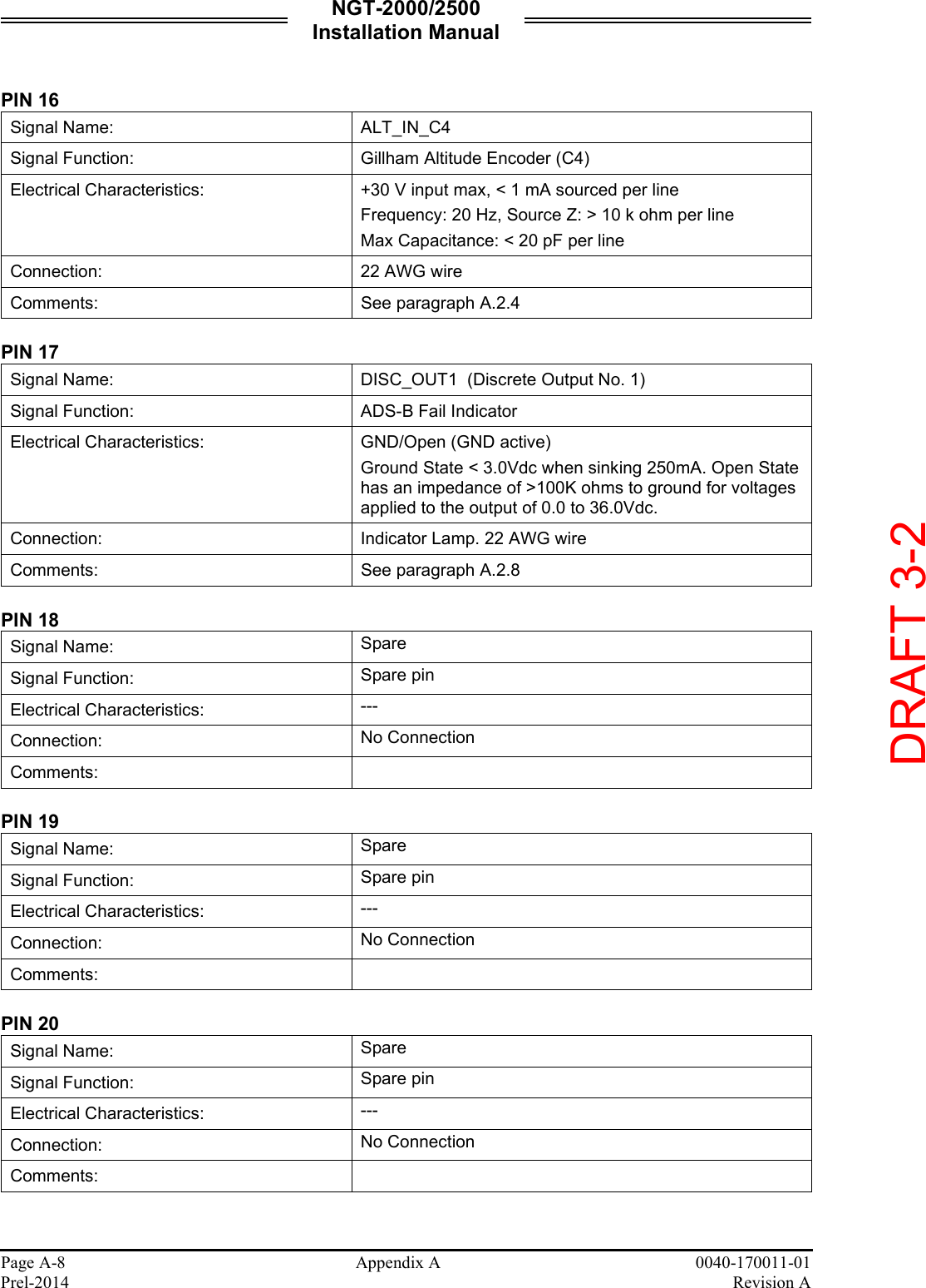
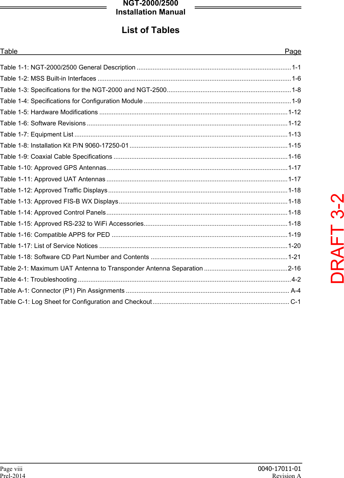
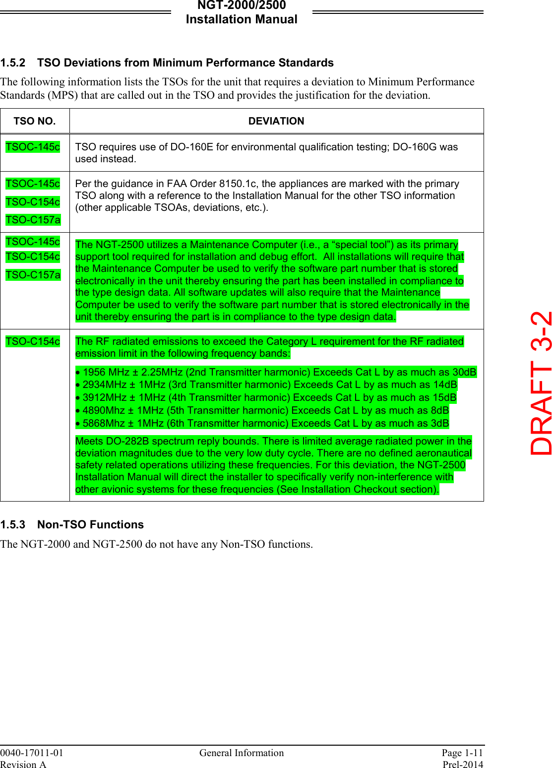
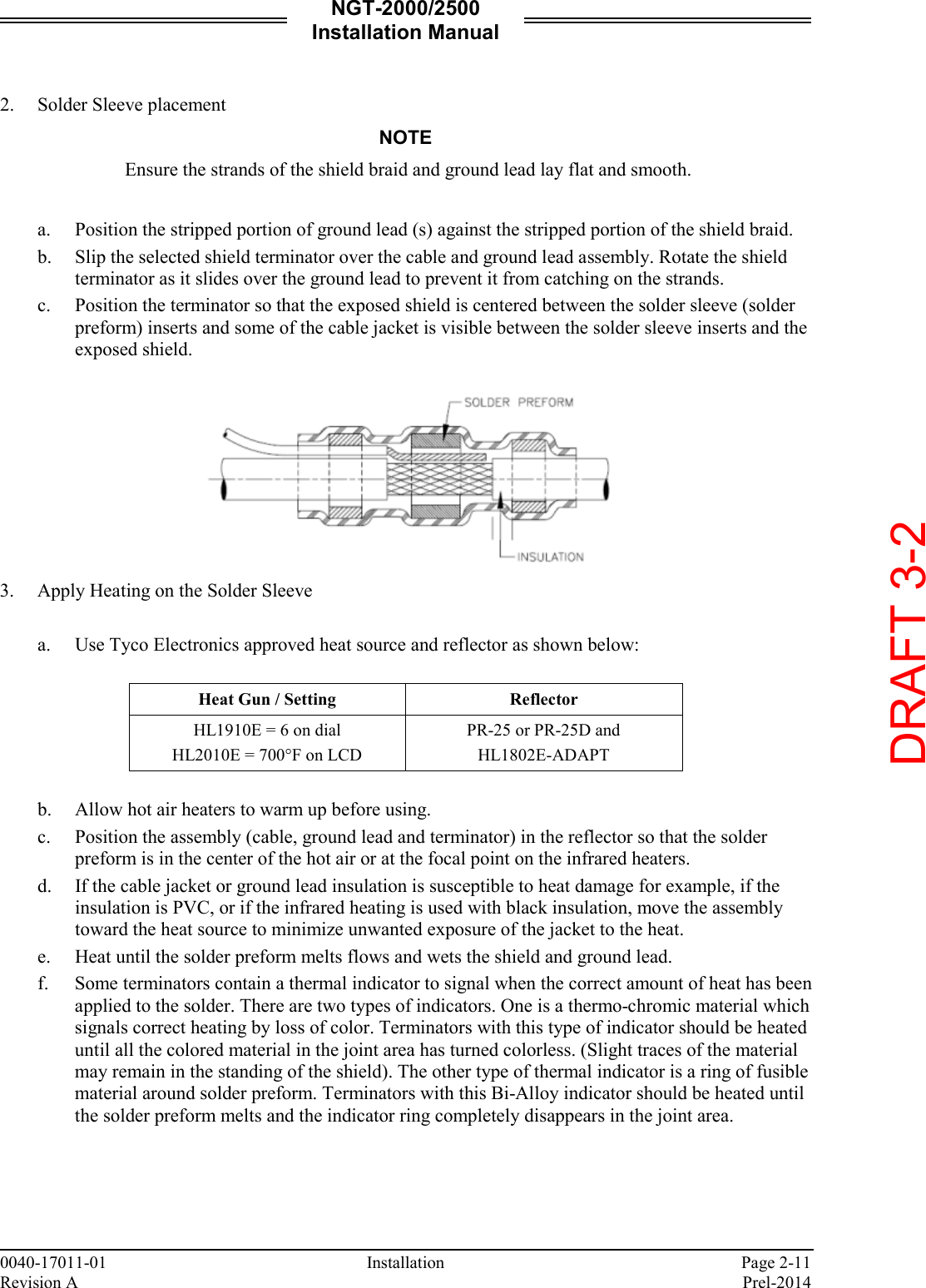
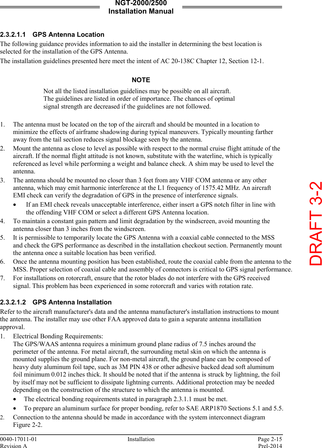
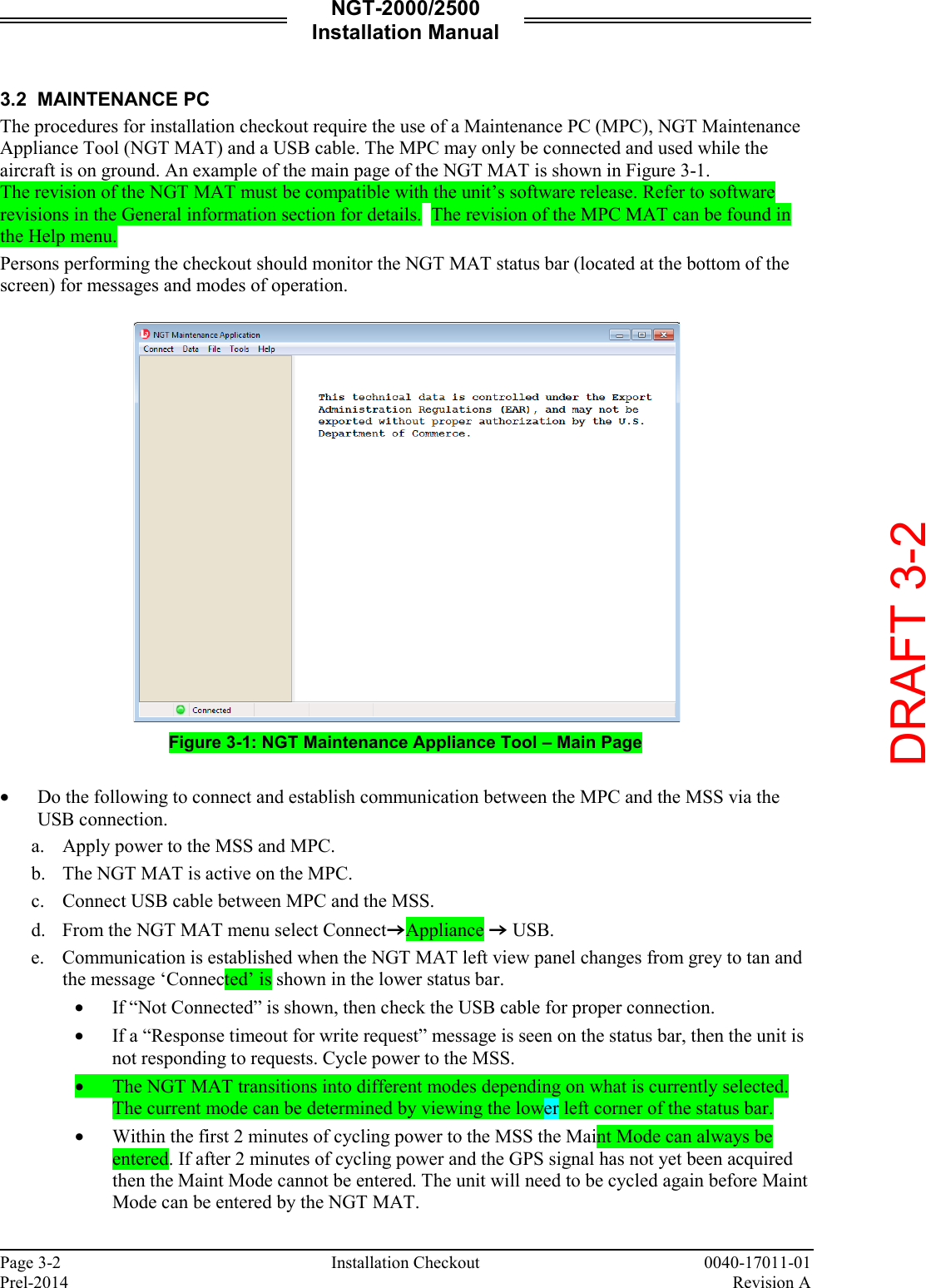
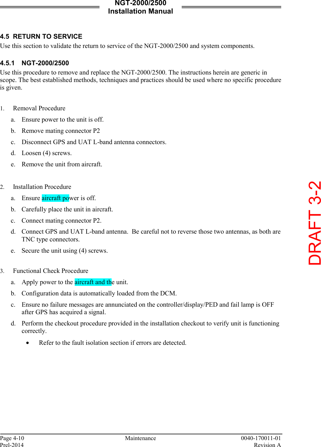
![NGT-2000/2500 Installation Manual 0040-17011-01 Page iii Revision A Prel-2014 List of Effective Pages Dates of original and changed pages are: Revision A...................................... Prel-2014 Total number of pages in this publication consists of the following: Title page A Page i thru x 1-1 thru 1-22 2-1 thru 2-20 3-1 thru 3-20 4-1 thru 4-12 A-1 thru A-22 B-1 thru B-2 Disclaimer Information in this manual is subject to change without notice and will not be updated after distribution. Changes to this manual will be reflected in the next revision. Revisions replace the entire manual and are incorporated as needed in order to keep information accurate and up-to-date. Avionics Systems does provide a listing of all publications and directives with their current revision to insure up-to-date information. See www.as.l-3com.com to get an up-to-date listing of all Avionics Systems technical publications and directives. Contact Avionics Systems Customer Care [1-616-949-6600] to determine availability of technical publications and directives. DRAFT 3-2](https://usermanual.wiki/Aviation-Communications-and-Surveillance-Systems/MSS25/User-Guide-2417146-Page-5.png)
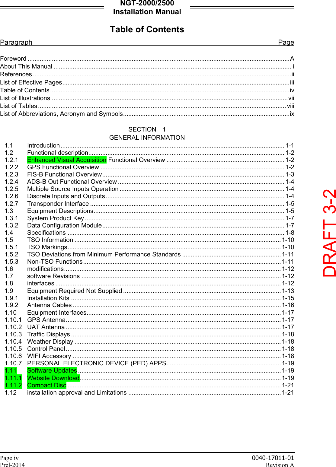
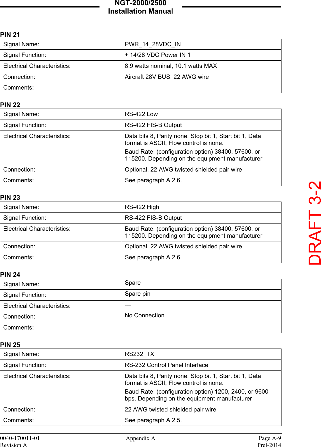
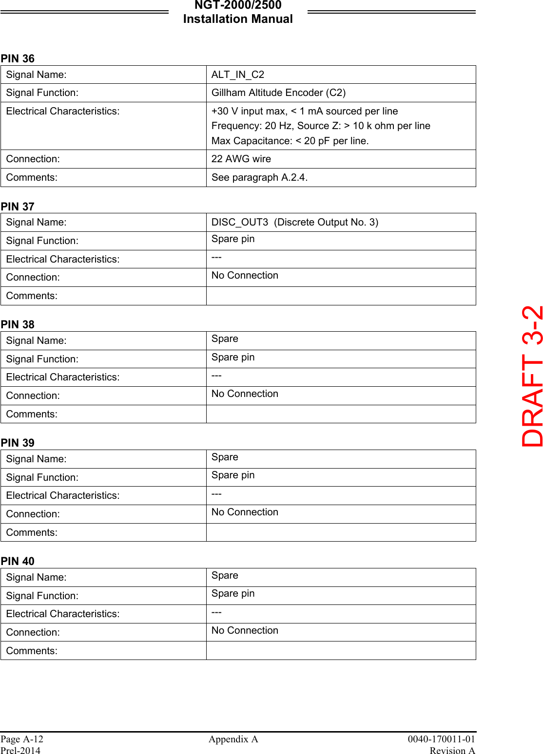
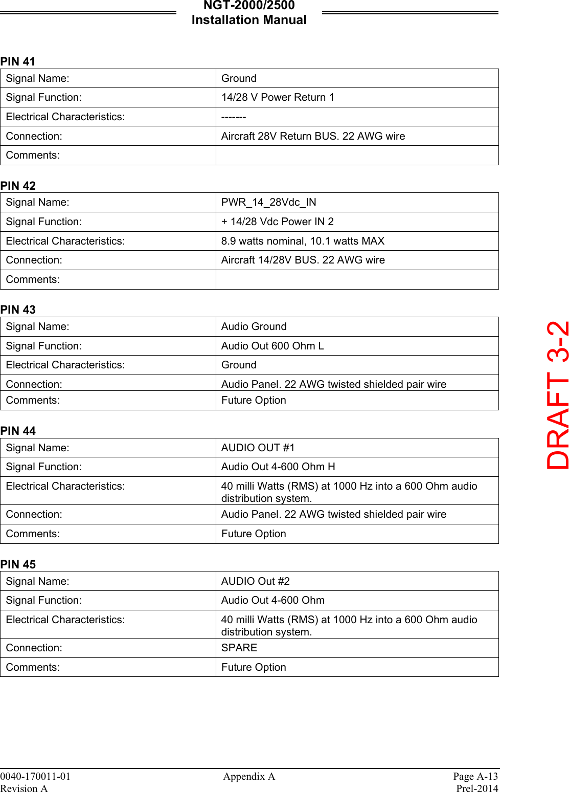
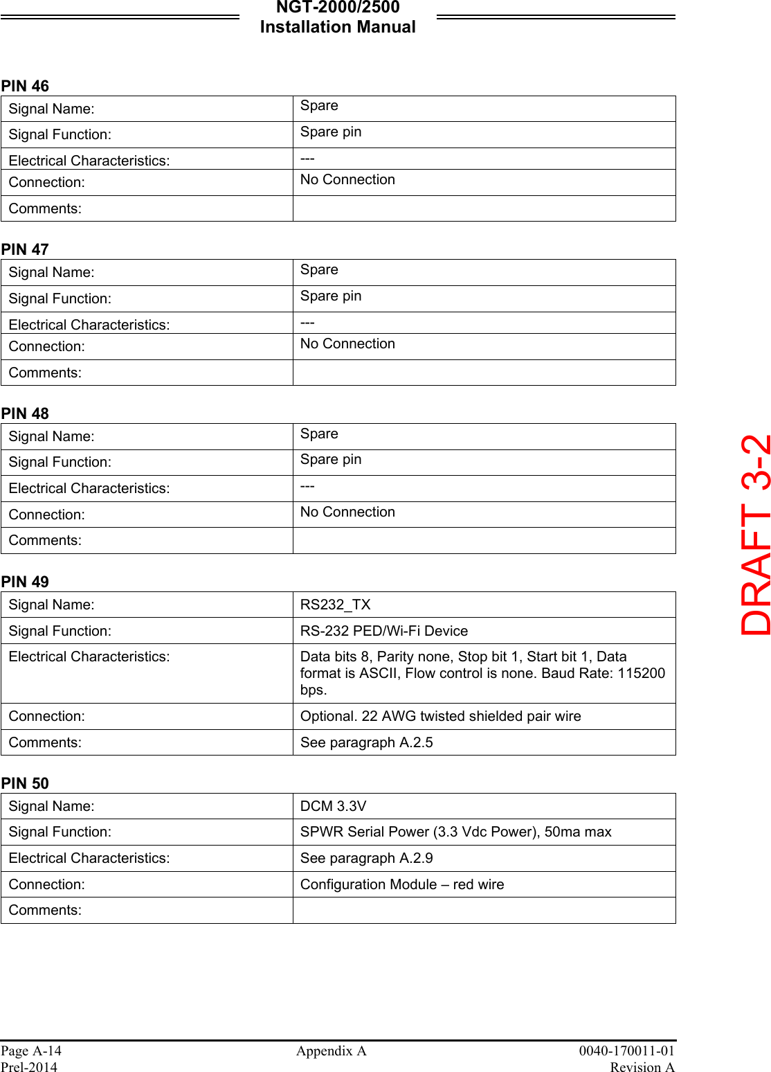
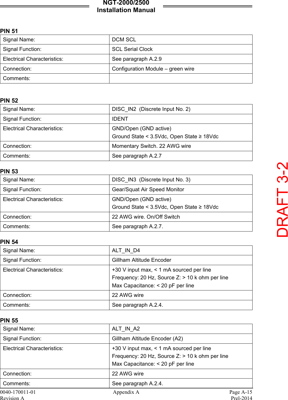
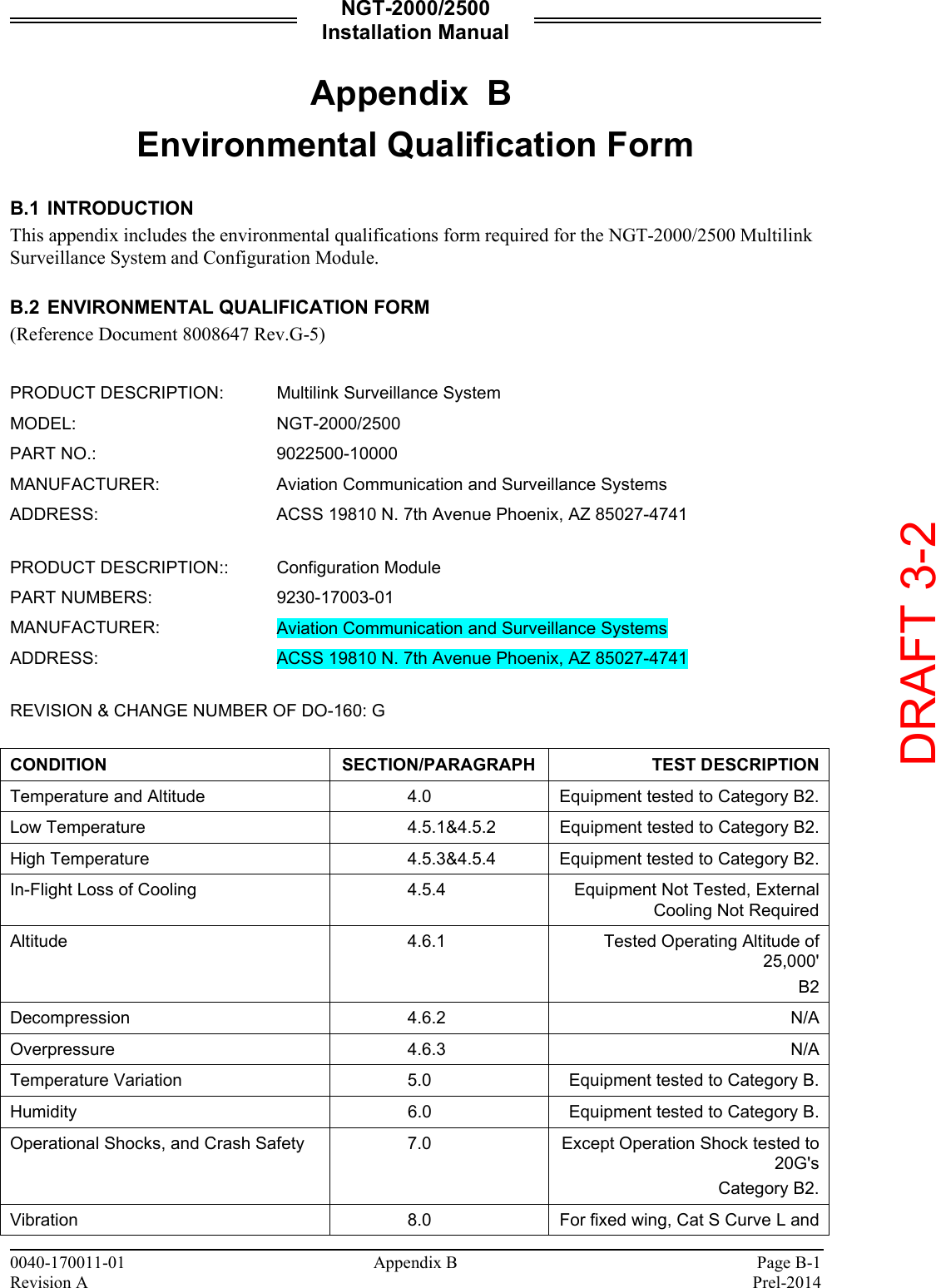
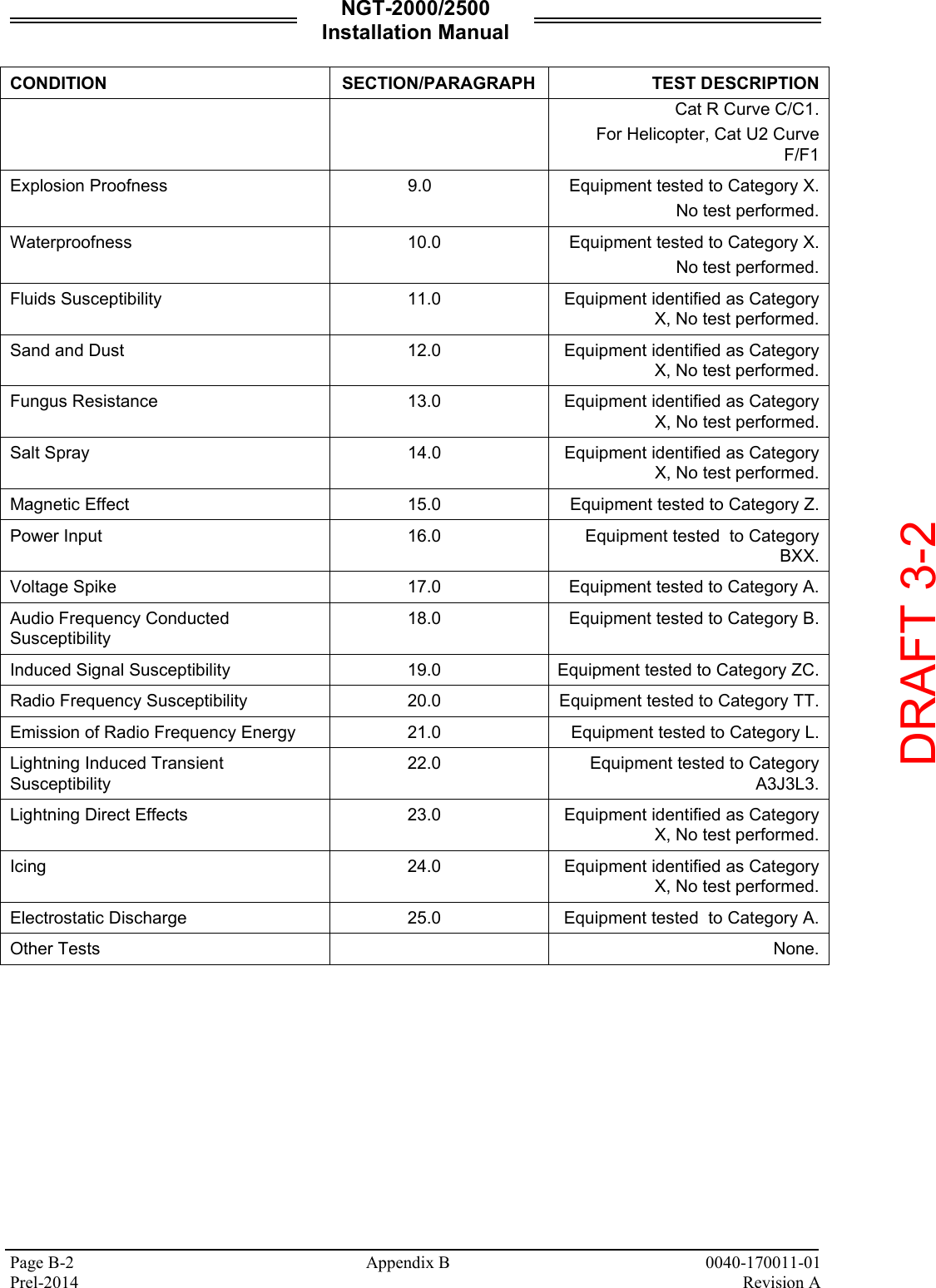
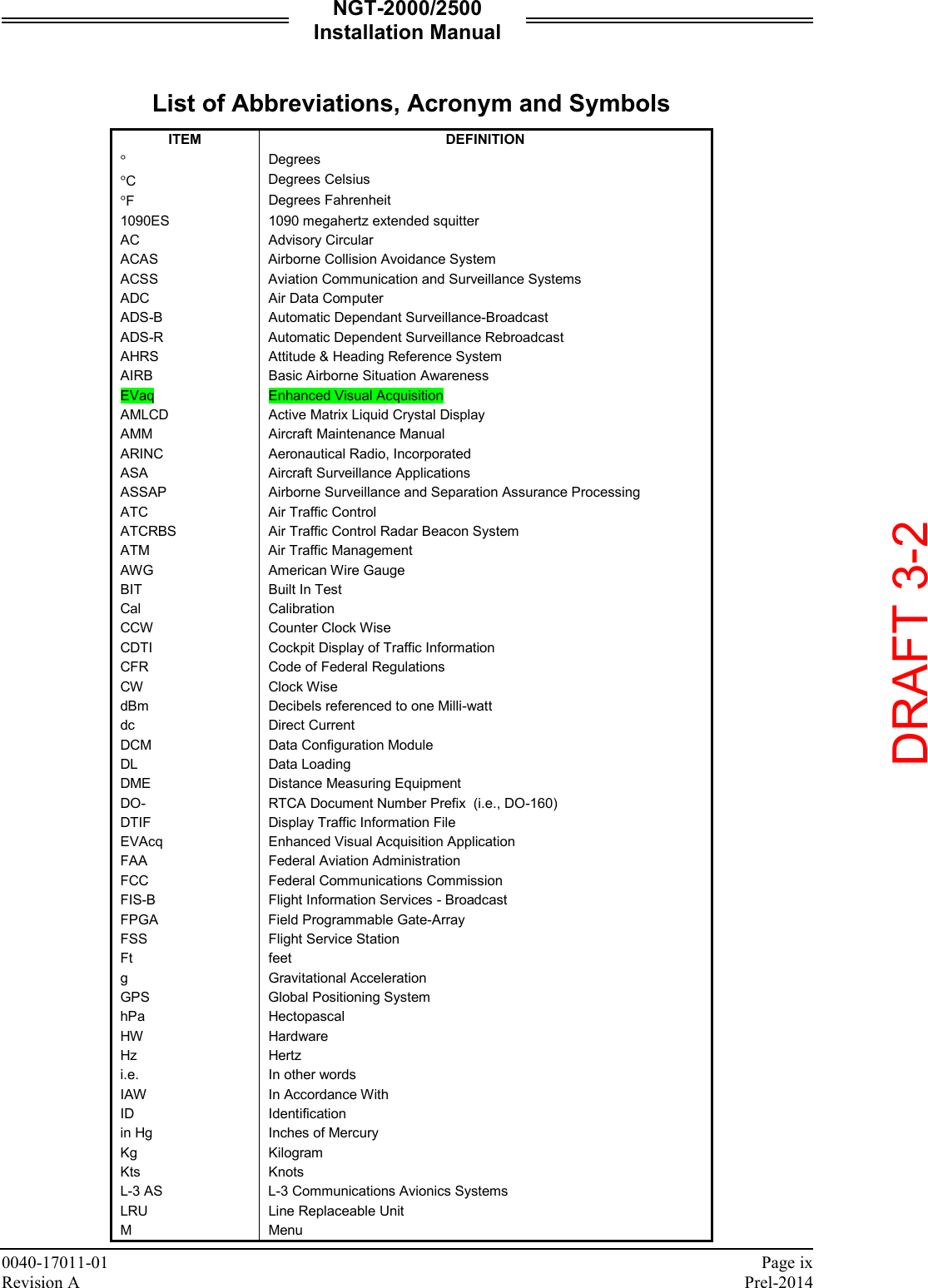
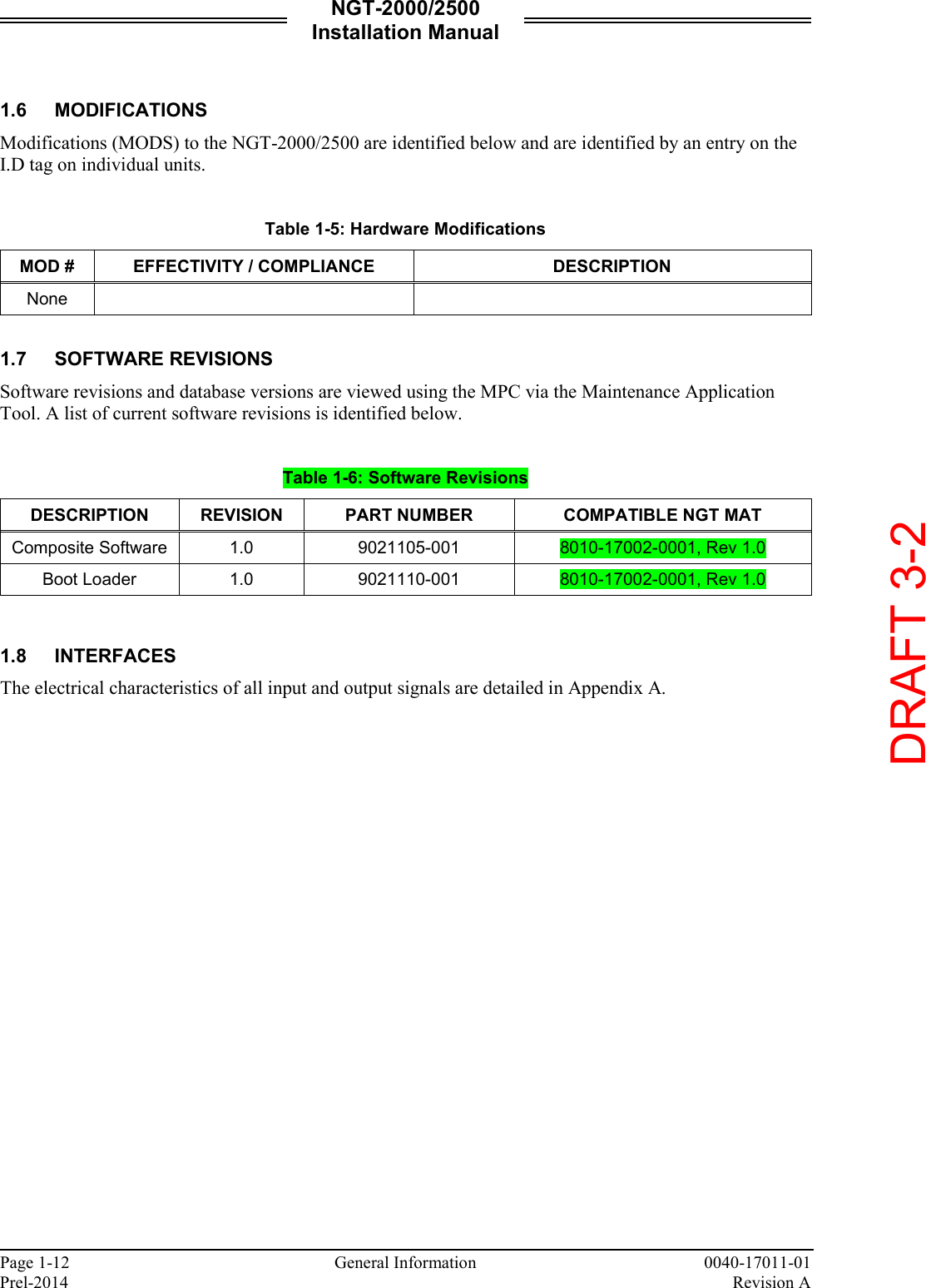
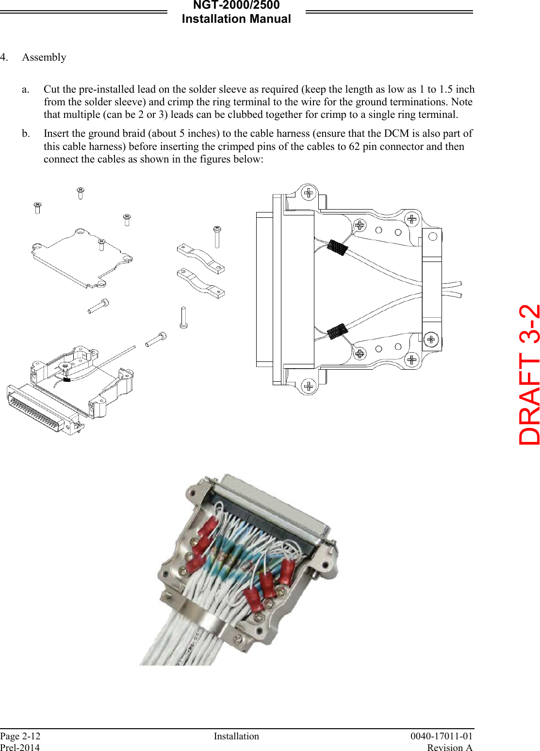
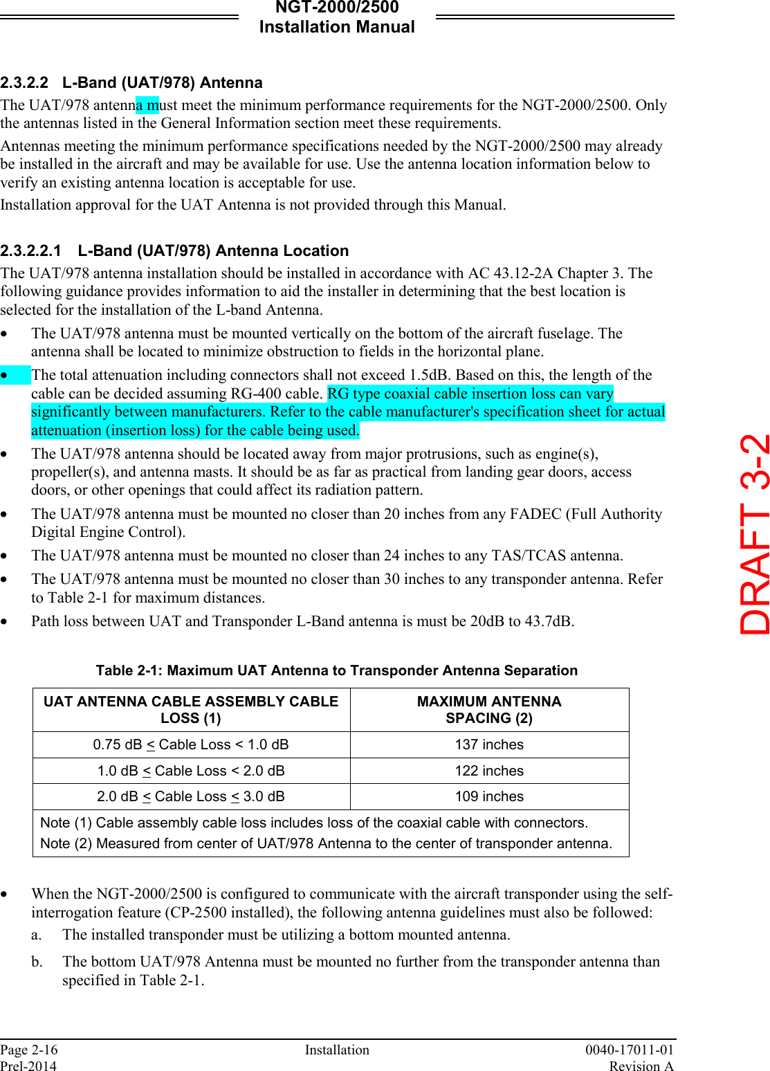
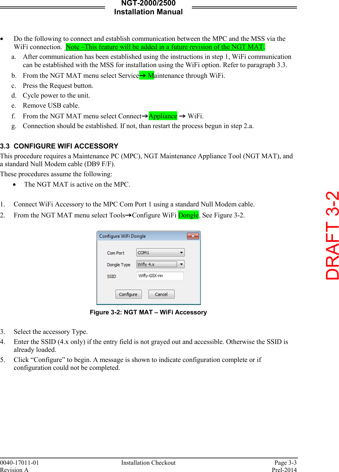
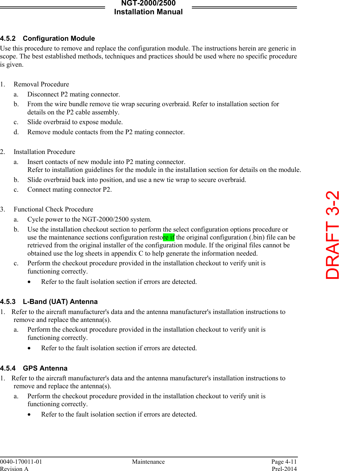
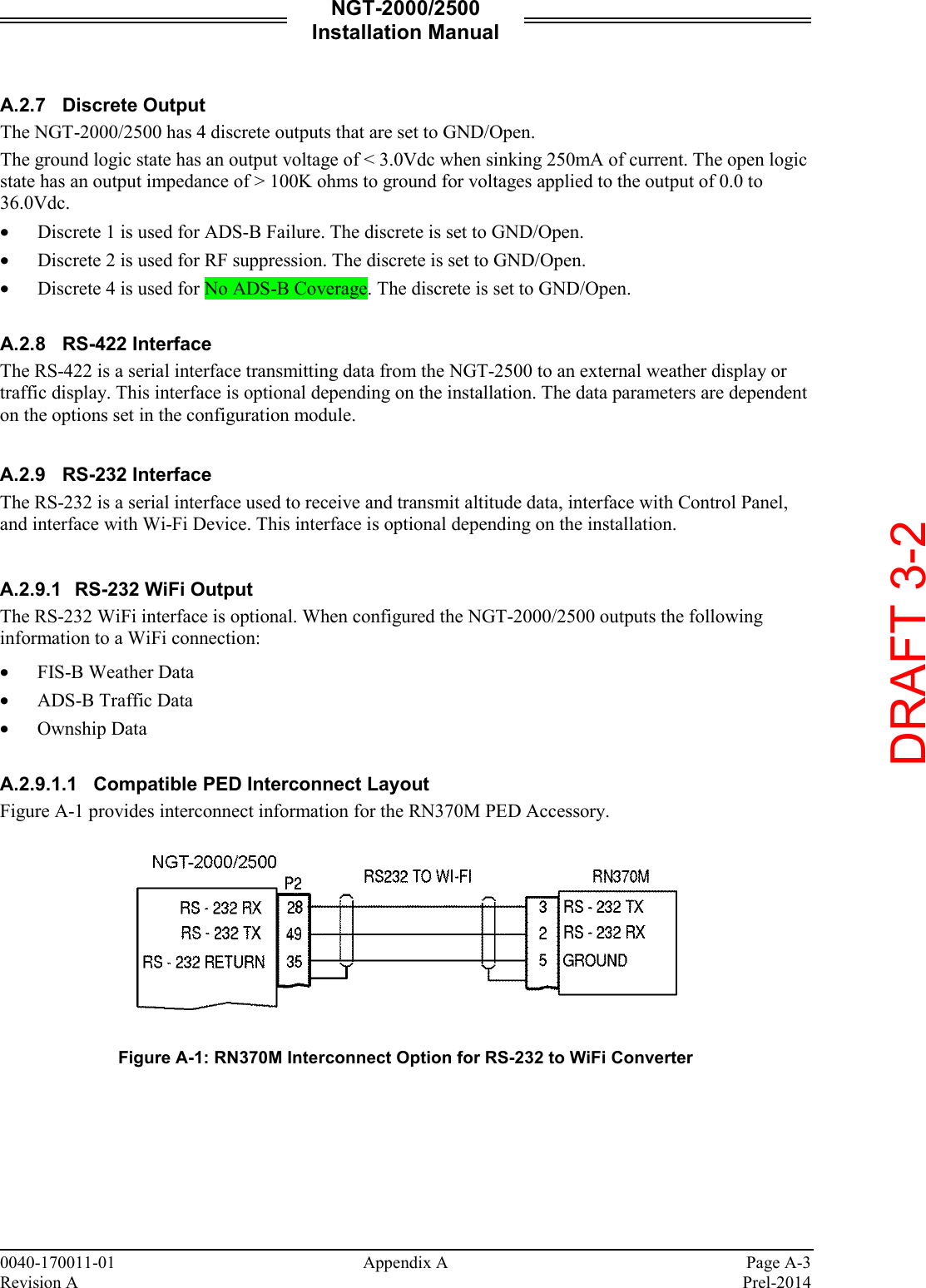
![NGT-2000/2500 Installation Manual Page vi 0040-17011-01 Prel-2014 Revision A Table of Contents (cont.) Paragraph Page Appendix A NGT-2000/2500 Interface Signal Name & Cable Characteristics A.1 Introduction .................................................................................................................................A-1 A.2 Input and Output Interfaces ........................................................................................................A-1 A.2.1 Input Power ................................................................................................................................A-1 A.2.2 I2C Serial Bus (Configuration Module) ........................................................................................A-1 A.2.3 RF Suppression Bus ...................................................................................................................A-1 A.2.4 Gillham Input (Altitude Input) ......................................................................................................A-1 A.2.5 ARINC 429 Output ......................................................................................................................A-2 A.2.6 Discrete Input .............................................................................................................................A-2 A.2.7 Discrete Output ...........................................................................................................................A-3 A.2.8 RS-422 Interface ........................................................................................................................A-3 A.2.9 RS-232 Interface ........................................................................................................................A-3 A.3 Pin Definition Summary ..............................................................................................................A-4 A.4 connector [J2] .............................................................................................................................A-5 Appendix B Environmental Qualification Form B.1 Introduction .................................................................................................................................B-1 B.2 Environmental Qualification Form ..............................................................................................B-1 Appendix C Configuration and Checkout Log DRAFT 3-2](https://usermanual.wiki/Aviation-Communications-and-Surveillance-Systems/MSS25/User-Guide-2417146-Page-8.png)
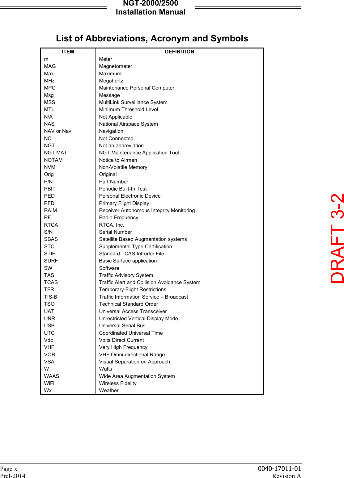
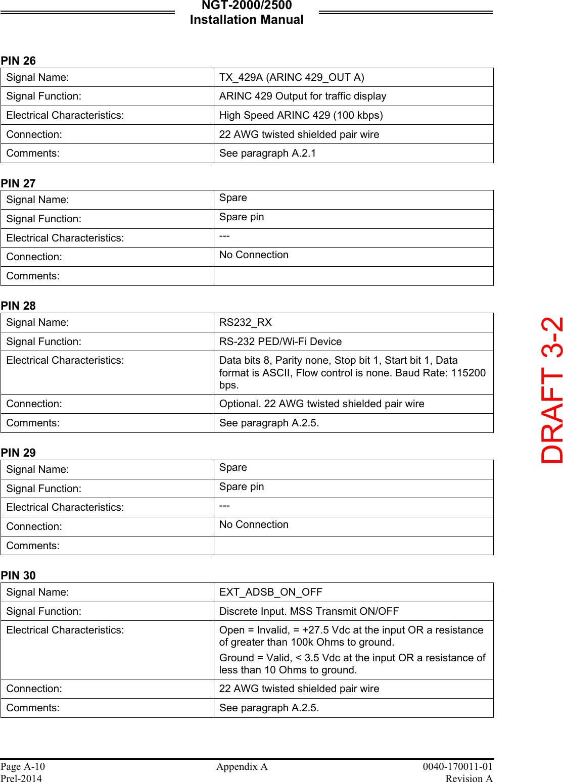
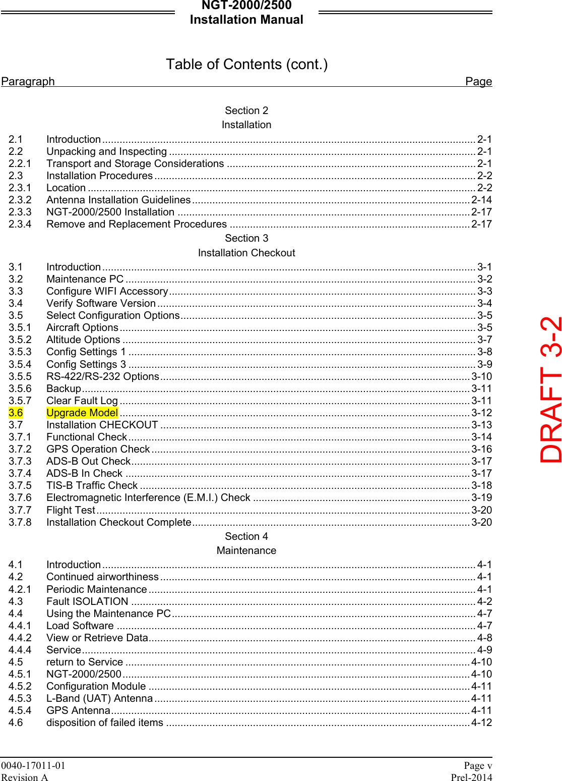
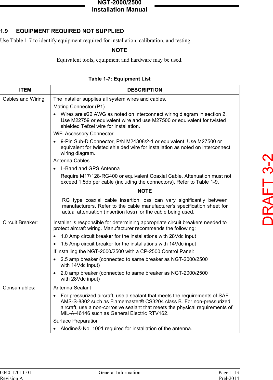
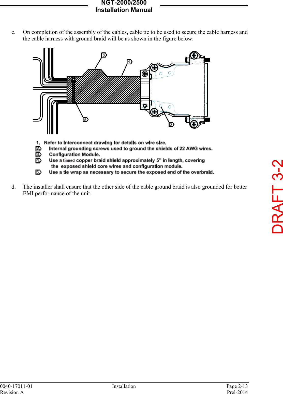
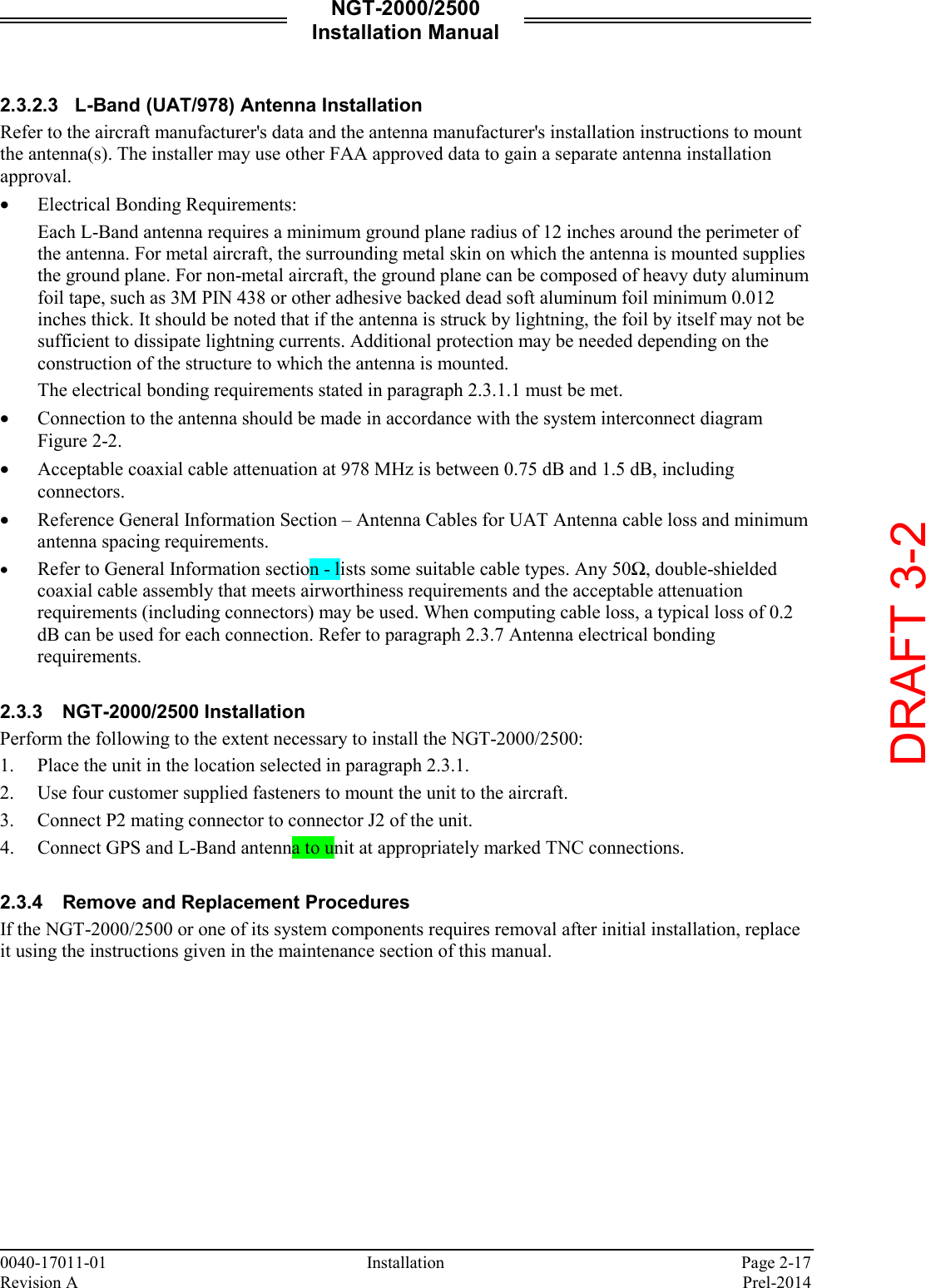
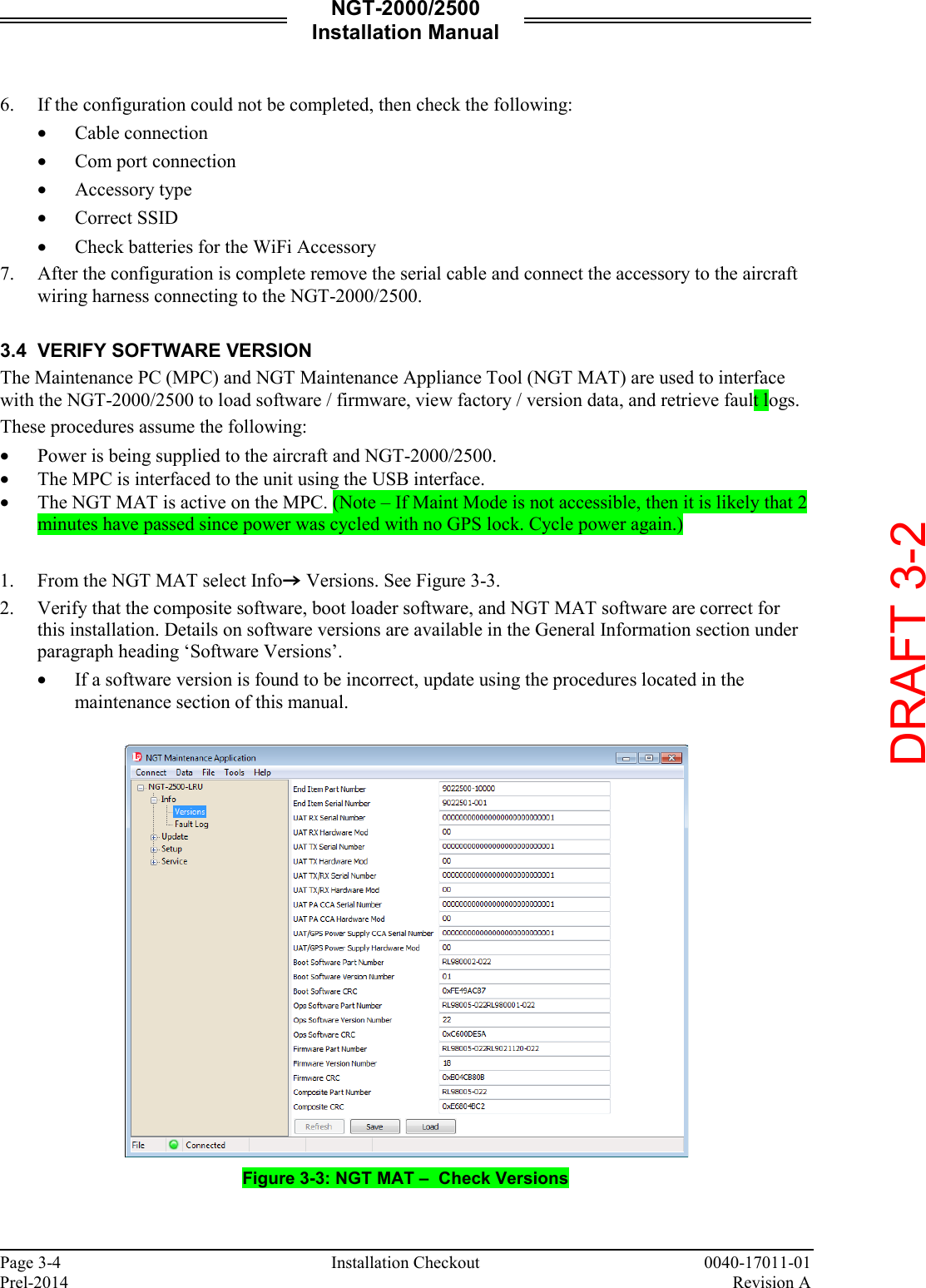
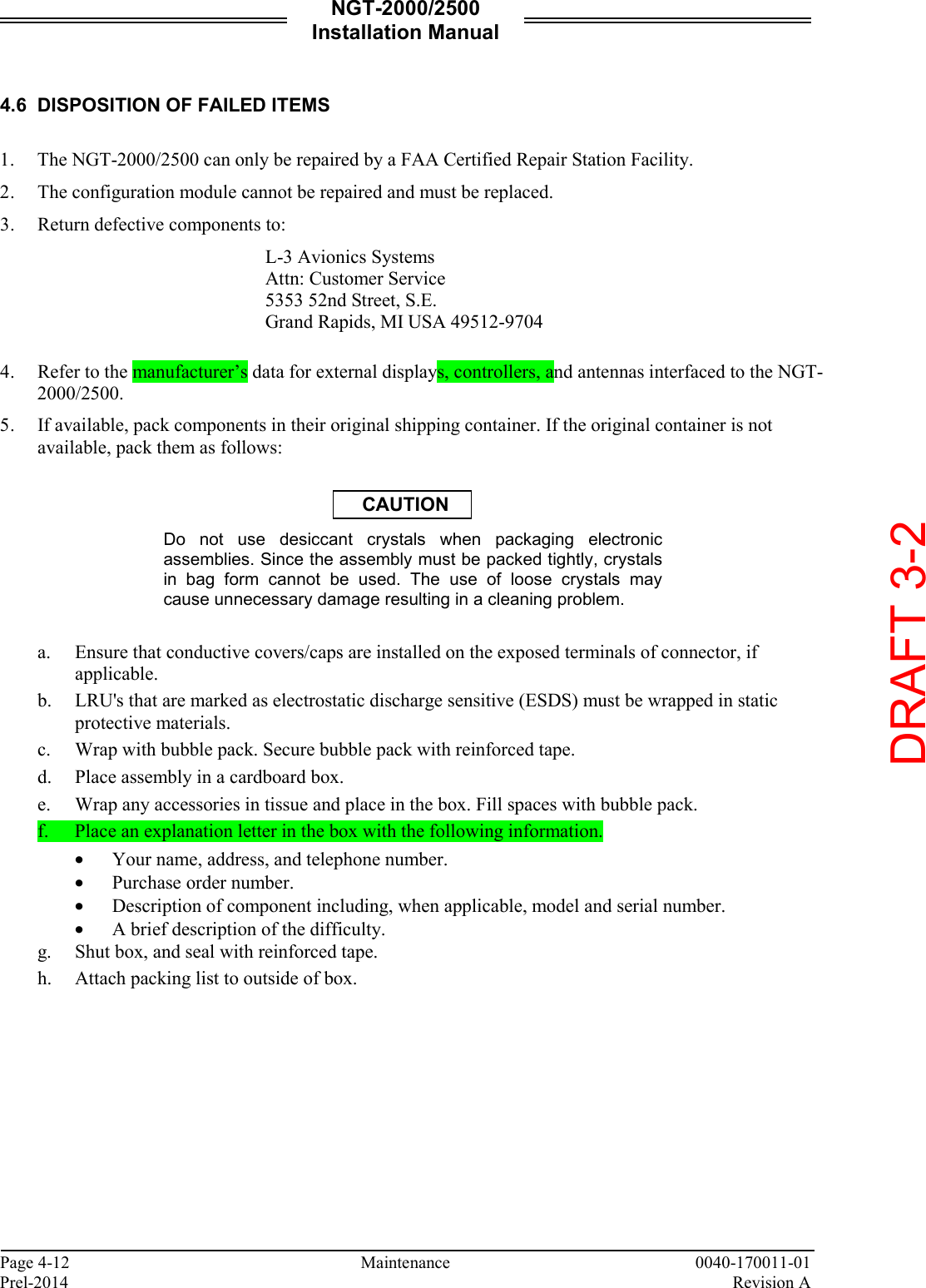
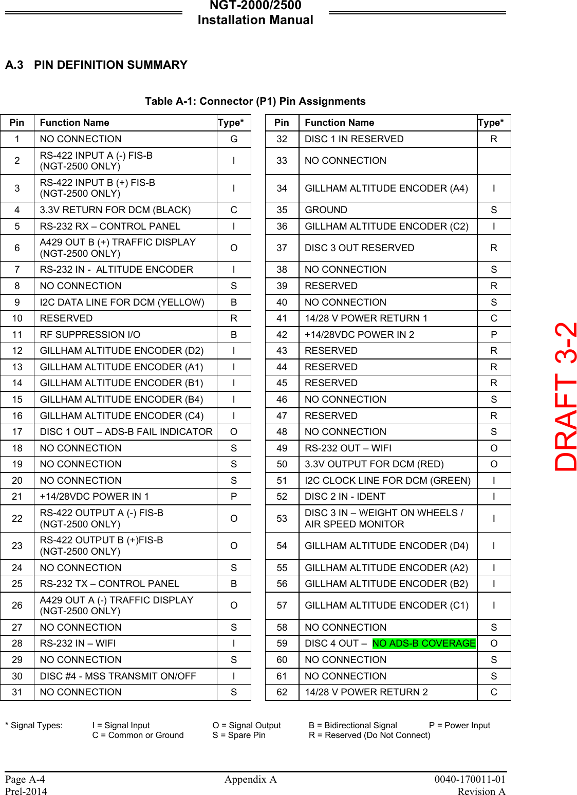
![NGT-2000/2500 Installation Manual Page 1-8 General Information 0040-17011-01 Prel-2014 Revision A 1.4 SPECIFICATIONS Table 1-3: Specifications for the NGT-2000 and NGT-2500 PART NUMBER: 9022500-10000 CERTIFICATION: TSO-C145c, C154c, C157a, C195a. For more information on TSO information, refer to paragraph 1.5. Listed are current certifications at time of publication, contact Field Service Engineering for latest certification information. ADVISORY CIRCULARS: AC 20-165A (ADS-B Out), AC-20-172A (ADS-B In), AC20-138D (GPS), AC20-149A (FIS-B) RTCA COMPLIANCE: Environmental Category: DO-160G (See Environmental Qualification Form in Appendix B.) Software Category: DO-178B, Level C Hardware Category: DO-254 Level C Other: DO-229D, DO-282B, DO-317A, DO-267A, FAR 91.227 SIZE: Height 2.8 inch [71.6 mm] Width 4.5 inch [114 mm] Length 5.7 inch [145 mm] WEIGHT: 1.0 lb nominal CHASSIS GROUND: Bonding impedance between aircraft ground and the MSS Chassis must be less than 2.5 milliohms. POWER REQUIREMENTS: Main Power 14 Vdc/28 Vdc, 8.9 watts nominal, 10.1 watts MAX ELECTRICAL CONNECTORS: • J2 [62 pin] Mates with P/N M24308/2-14 (TE connectivity) or L-3AS P/N 9001640-002 with backshell P/N 3050-17000-01 (See installation kit P/N 9060-17250-01) • J1 is a Mini-b USB connection (5 pin) Maintenance Port • RF Connector (2): 5W5 Coax D-Sub OPERATING TEMPERATURE: -45° to +70°C (-49° to 158°F) STORAGE TEMPERATURE: -55° to +85°C (-67° to +185°F) MAXIMUM ALTITUDE: Operating:18,000ft (5486 meters) Tested: 25,000 ft (7620 meters) NOTE: the unit is tested at 25,000 ft, however the UAT device is restricted to 18,000 ft for transmit. SCHEDULED MAINTENANCE: None SERVICE LIFE: The unit has unlimited service life. REPAIRABILITY: Repairs performed at the FAA certificated Repair Station co-located at the OEM (equipment) facility. DRAFT 3-2](https://usermanual.wiki/Aviation-Communications-and-Surveillance-Systems/MSS25/User-Guide-2417146-Page-20.png)
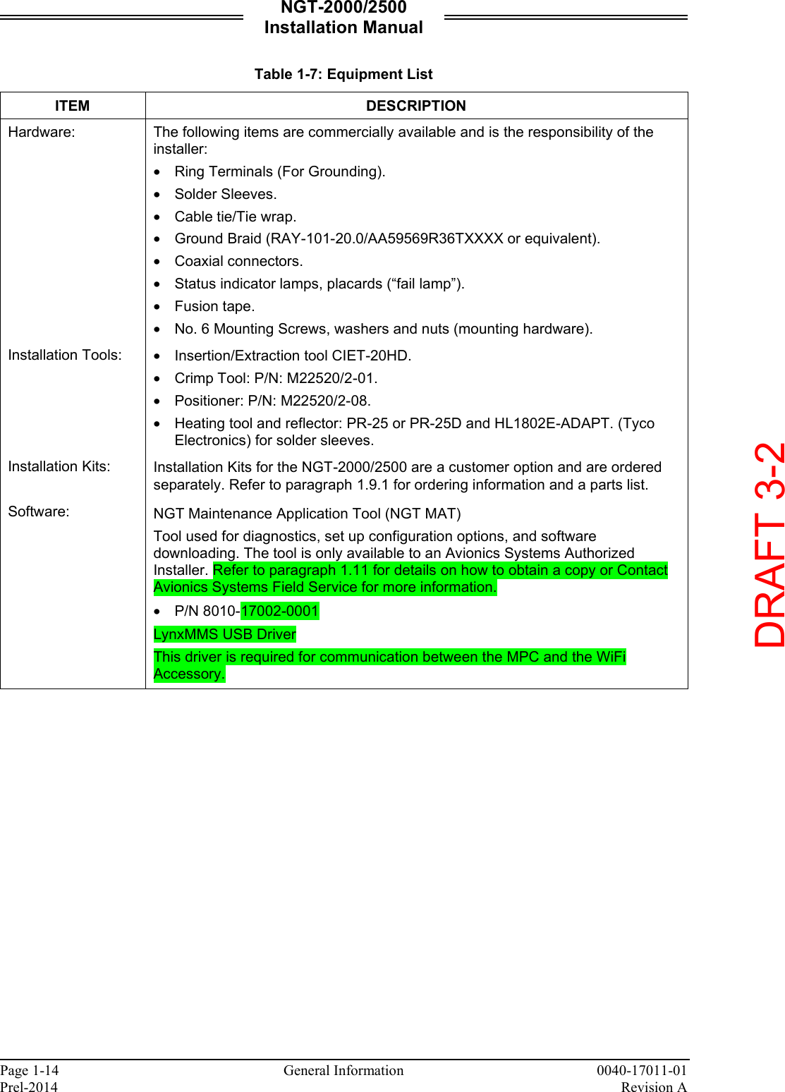
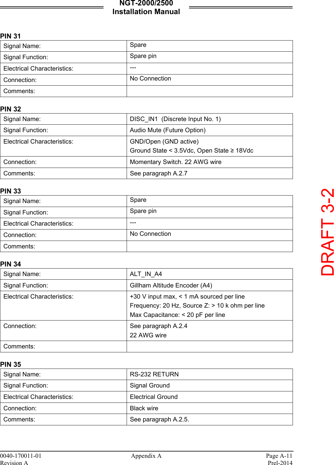
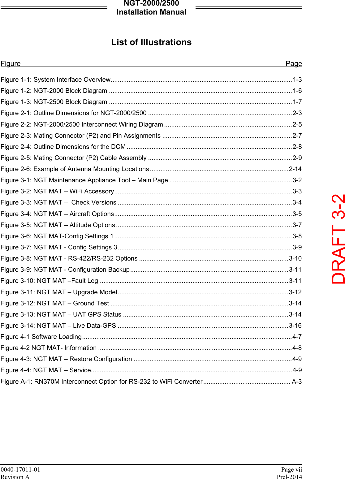
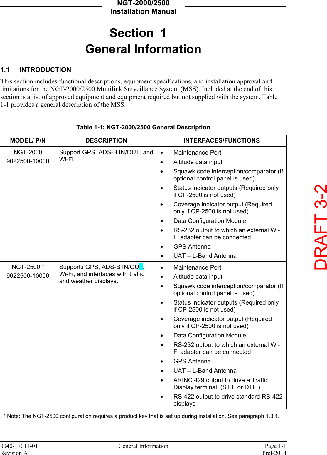
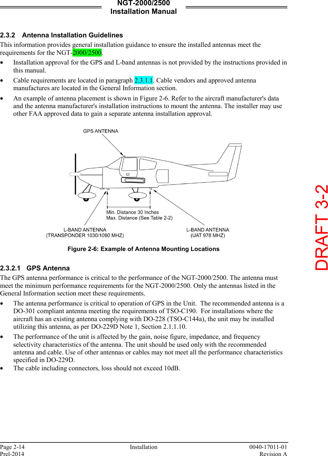
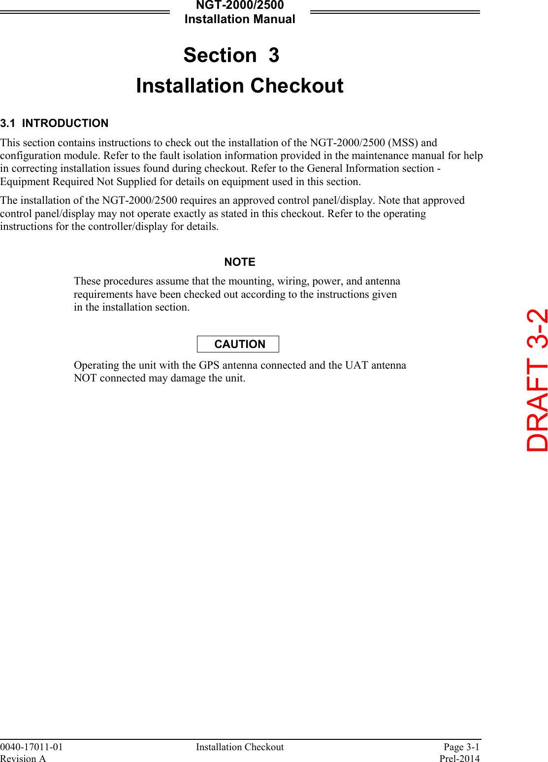
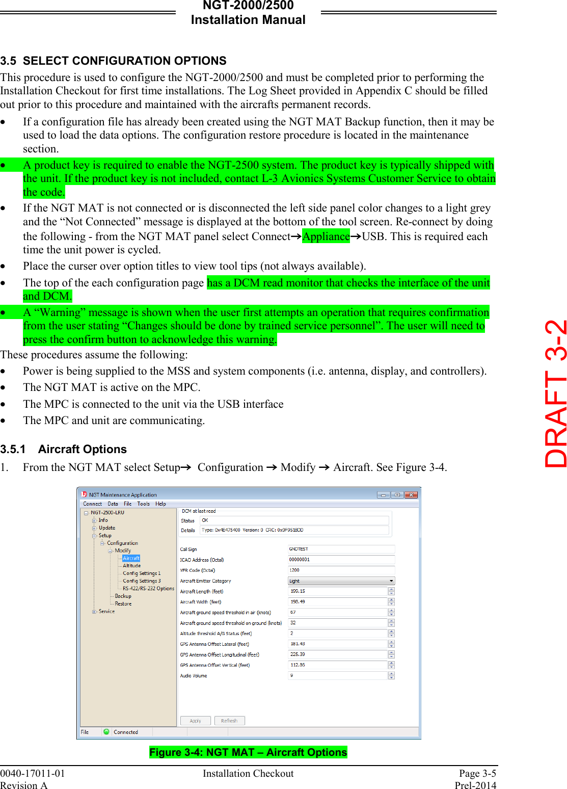
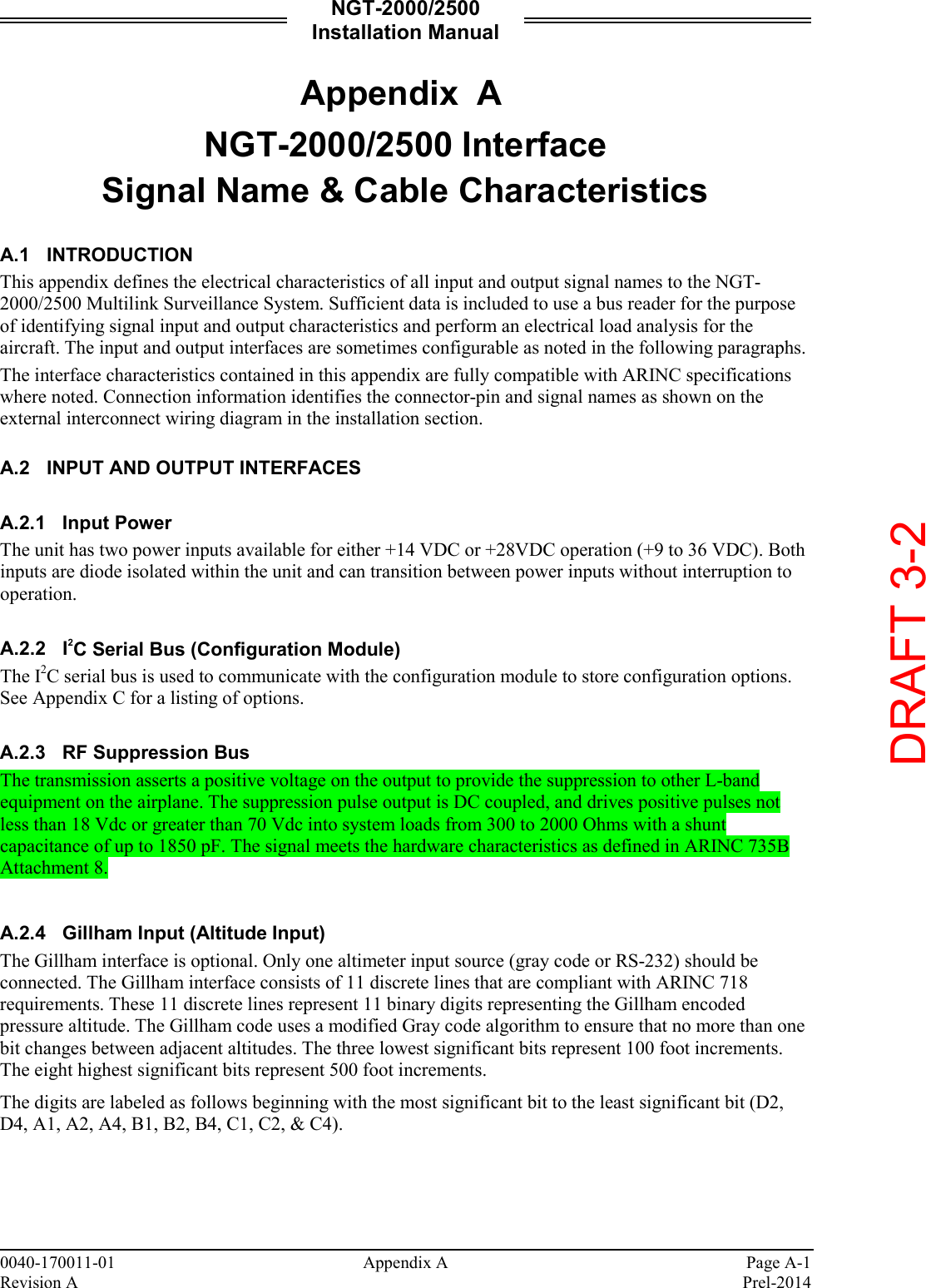
![NGT-2000/2500 Installation Manual Page 1-16 General Information 0040-17011-01 Prel-2014 Revision A 1.9.2 Antenna Cables Table 1-9 lists examples of the recommended antenna cable vendors and the type of cable to be used for specific lengths of cable. Any cable meeting specifications is acceptable for the installation. Table 1-9: Coaxial Cable Specifications INSERTION LOSS (DB/100FT) [1] CARLISLE IT TYPE [2] MIL-C-17 TYPE [3] RG TYPE 18.5 N/A M17/128-RG400 RG-400 11.1 N/A M17/112-RG304 RG-304 9.2 N/A M17/127-RG393 RG-393 15.2 3C142B N/A N/A 9.2 311601 N/A N/A 7.5 311501 N/A N/A 5.8 311201 N/A N/A 3.8 310801 N/A N/A [1] RG type coaxial cable insertion loss can vary significantly between manufacturers. The insertion loss for RG type cables shown in this column is considered 'worst case'. Refer to the cable manufacturer's specification sheet for actual attenuation (insertion loss) for the cable being used. [2] Supplier information (for reference only): Carlisle IT 5300 W. Franklin Drive Franklin, WI 53132 Tel: 800-327-9473 414-421-5300 Fax: 414-421-5301 www.carlisle.com [3] Supplier information: See current issue of Qualified Products List QPL-17. DRAFT 3-2](https://usermanual.wiki/Aviation-Communications-and-Surveillance-Systems/MSS25/User-Guide-2417146-Page-28.png)


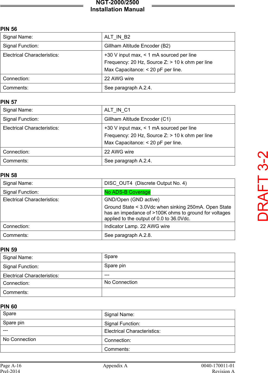
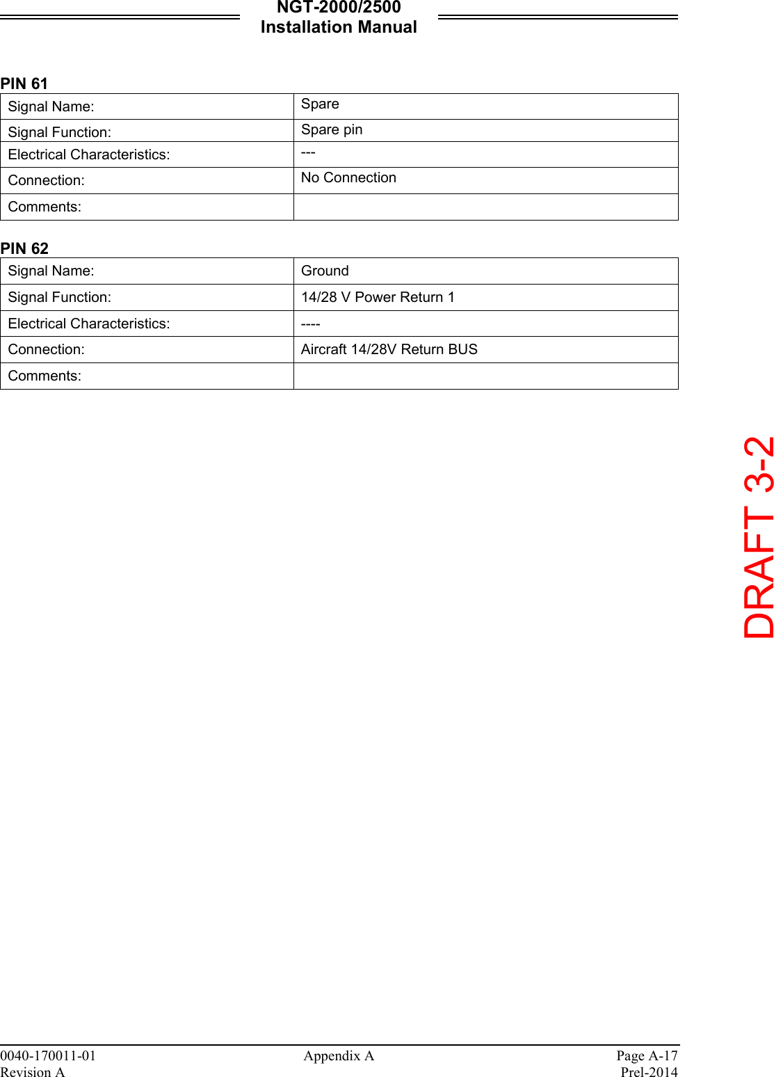
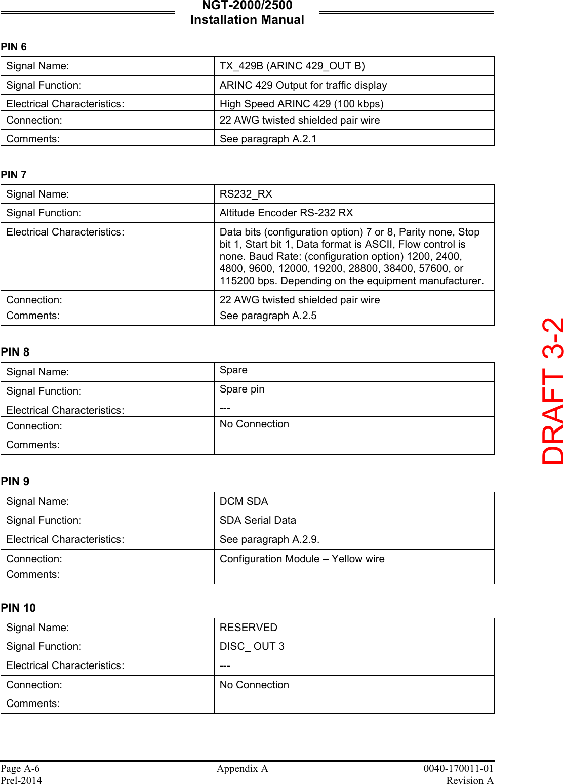
![NGT-2000/2500 Installation Manual 0040-170011-01 Appendix A Page A-5 Revision A Prel-2014 A.4 CONNECTOR [J2] PIN 1 Signal Name: Spare Signal Function: Spare pin Electrical Characteristics: --- Connection: No Connection Comments: PIN 2 Signal Name: RS422_RX2A Signal Function: RS-422 FIS-B Input Electrical Characteristics: Data bits 8, Parity none, Stop bit 1, Start bit 1, Data format is ASCII, Flow control is none. Connection: Optional. 22 AWG twisted shielded pair wire Comments: See paragraph A.2.6. PIN 3 Signal Name: RS422_RX2B Signal Function: RS-422 FIS-B Input Electrical Characteristics: Data bits 8, Parity none, Stop bit 1, Start bit 1, Data format is ASCII, Flow control is none. Connection: Optional. 22 AWG twisted shielded pair wire. Comments: See paragraph A.2.6. PIN 4 Signal Name: DCM GND Signal Function: SGND Serial Ground Electrical Characteristics: See paragraph A.2.9 Connection: Configuration Module – Black wire Comments: PIN 5 Signal Name: RS232_RX Signal Function: RS-232 Control Panel Interface Electrical Characteristics: Data bits 8, Parity none, Stop bit 1, Start bit 1, Data format is ASCII, Flow control is none. Baud Rate: (configuration option) 1200, 2400, or 9600 bps. Depending on the equipment manufacturer Connection: 22 AWG twisted shielded pair wire. Comments: See paragraph A.2.5. DRAFT 3-2](https://usermanual.wiki/Aviation-Communications-and-Surveillance-Systems/MSS25/User-Guide-2417146-Page-89.png)
![NGT-2000/2500 Installation Manual 0040-170011-01 Appendix A Page A-7 Revision A Prel-2014 PIN 11 Signal Name: SUPPR_BUS Signal Function: RF suppression input (DISC_OUT 2) Electrical Characteristics: Connection: Aircraft Suppression Bus. 22 AWG twisted shielded wire Comments: See paragraph A.2.3 PIN 12 Signal Name: EXT_ALT_ENCODER[11] Signal Function: Gillham Altitude Encoder (D2) Electrical Characteristics: +30 V input max, < 1 mA sourced per line Frequency: 20 Hz, Source Z: > 10 k ohm per line Max Capacitance: < 20 pF per line Connection: 22 AWG wire Comments: See paragraph A.2.4 PIN 13 Signal Name: ALT_IN_A1 Signal Function: Gillham Altitude Encoder (A1) Electrical Characteristics: +30 V input max, < 1 mA sourced per line Frequency: 20 Hz, Source Z: > 10 k ohm per line Max Capacitance: < 20 pF per line Connection: 22 AWG wire Comments: See paragraph A.2.4 PIN 14 Signal Name: ALT_IN_B1 Signal Function: Gillham Altitude Encoder (B1) Electrical Characteristics: +30 V input max, < 1 mA sourced per line Frequency: 20 Hz, Source Z: > 10 k ohm per line Max Capacitance: < 20 pF per line. Connection: 22 AWG wire Comments: See paragraph A.2.4 PIN 15 Signal Name: ALT_IN_B4 Signal Function: Gillham Altitude Encoder (B4) Electrical Characteristics: +30 V input max, < 1 mA sourced per line Frequency: 20 Hz, Source Z: > 10 k ohm per line Max Capacitance: < 20 pF per line. Connection: 22 AWG wire Comments: See paragraph A.2.4 DRAFT 3-2](https://usermanual.wiki/Aviation-Communications-and-Surveillance-Systems/MSS25/User-Guide-2417146-Page-91.png)