Aviation Communications and Surveillance Systems MSS25 Multi Link Transponder User Manual FrontMatter
Aviation Communications and Surveillance Systems (ACSS), LLC. Multi Link Transponder FrontMatter
Installation Manual
0040-17011-01 (Revision A)
Prel-2014
LYNX TM
Multilink Surveillance System
NGT-2000/2500
Part Number 9022500-10000
Installation Manual
This manual contains installation instructions and
recommended flightline maintenance information for
the NGT-2000/2500 Multilink Surveillance System
and Configuration Module. Guidelines for external
equipment necessary for installation are included.
This information is supplemented and kept current by
revisions, service letters and service bulletins.
DRAFT 3-2

Page A 0040-17011-01
Prel-2014 Revision A
Foreword
This manual provides information intended for use by persons who, in accordance with current regulatory
requirements, are qualified to install this equipment. Installation requirements may vary, depending on the
particularities of each aircraft, and this manual is intended as a guideline for that purpose. This manual
assumes familiarity with the setup and operation of the aircraft systems that interface with the NGT-
2000/2500.
If further information is required, please contact:
L-3 Avionics Systems
Attn: Field Service Engineering
5353 52nd Street, S.E.
Grand Rapids, MI USA 49512-9704
Telephone: (800) 453-0288 or (616) 949-6600
Fax: (616) 977-6898
We welcome your comments concerning this manual. Although every effort has been made to keep it free
of errors, some may occur. When reporting a specific problem, please describe it briefly and include the
manual part number, the paragraph/figure/table number, and the page number. Send your comments to:
L-3 Avionics Systems
Attn: Technical Publications
5353 52nd Street, S.E.
Grand Rapids, MI USA 49512-9704
Telephone: (800) 453-0288 or (616) 949-6600
Fax: (616) 977-6898
WARNING
INFORMATION SUBJECT TO EXPORT CONTROL LAWS
This technical data is controlled under the Export Administration
Regulations (EAR) and may not be exported without proper authorization
by the U.S. Department of Commerce.
Copyright 2014
L-3 Avionics Systems
Trademarks
Lynx TM is a trademark of L-3 Avionics Systems
Patent Pending
DRAFT 3-2

NGT-2000/2500
Installation Manual
0040-17011-01 Page i
Revision A Prel-2014
ABOUT THIS MANUAL
SECTION 1 – GENERAL INFORMATION
This section provides the following information: unit configurations, unit functionality, items
required but not supplied with the unit, equipment specifications, installation approval/limitations
and TSO approvals.
SECTION 2 - INSTALLATION
This section contains instructions to locate, assemble and install the NGT-2000/2500 as well as
information for unpacking equipment, and inspection procedure for in-shipment damage.
SECTION 3 – INSTALLATION CHECKOUT
This section contains instructions for post installation setup, post installation and return to service
checkout.
SECTION 4 – MAINTENANCE
This section contains general flightline maintenance procedures. It includes periodic maintenance,
troubleshooting and instructions for the return of defective components.
APPENDIX A – SIGNAL AND CABLE CHARACTERISTICS
This appendix defines the electrical characteristics of all input and output signals.
APPENDIX B – ENVIRONMENTAL QUALIFICATION FORM
This appendix provides the environmental qualification test data.
Descriptions for Warnings, Cautions and Notes described below.
WARNING
Used to give notice to or call one's attention to beforehand especially of
danger (such as a warning to a Flight Crew person or a warning to a
mechanic before performing a dangerous task).
CAUTION
Statement that expresses the need for heightened awareness to conditions
that can cause damage to equipment.
NOTE
Used to point out a procedure, event or practice that it is desirable to
highlight.
DRAFT 3-2

NGT-2000/2500
Installation Manual
Page ii 0040-17011-01
Prel-2014 Revision A
References
Publication Description
0040-17010-01 Pilot's Guide for the NGT-2000/2500
0040-17020-01 Pilots guide for the CP-2500 Control Panel
0040-17021-01 Installation Manual for the CP-2500 Control Panel
DRAFT 3-2

NGT-2000/2500
Installation Manual
0040-17011-01 Page iii
Revision A Prel-2014
List of Effective Pages
Dates of original and changed pages are:
Revision A...................................... Prel-2014
Total number of pages in this publication consists of the following:
Title page
A Page
i thru x
1-1 thru 1-22
2-1 thru 2-20
3-1 thru 3-20
4-1 thru 4-12
A-1 thru A-22
B-1 thru B-2
Disclaimer
Information in this manual is subject to change without notice and will not be updated after distribution.
Changes to this manual will be reflected in the next revision. Revisions replace the entire manual and are
incorporated as needed in order to keep information accurate and up-to-date.
Avionics Systems does provide a listing of all publications and directives with their current revision to
insure up-to-date information. See www.as.l-3com.com to get an up-to-date listing of all Avionics
Systems technical publications and directives. Contact Avionics Systems Customer Care [1-616-949-
6600] to determine availability of technical publications and directives.
DRAFT 3-2

NGT-2000/2500
Installation Manual
Page iv 0040-17011-01
Prel-2014 Revision A
Table of Contents
Paragraph Page
Foreword ....................................................................................................................................................... A
About This Manual ......................................................................................................................................... i
References ..................................................................................................................................................... ii
List of Effective Pages ................................................................................................................................... iii
Table of Contents .......................................................................................................................................... iv
List of Illustrations ........................................................................................................................................ vii
List of Tables ............................................................................................................................................... viii
List of Abbreviations, Acronym and Symbols ................................................................................................ ix
SECTION 1
GENERAL INFORMATION
1.1 Introduction ................................................................................................................................. 1-1
1.2 Functional description................................................................................................................. 1-2
1.2.1 Enhanced Visual Acquisition Functional Overview .................................................................... 1-2
1.2.2 GPS Functional Overview .......................................................................................................... 1-2
1.2.3 FIS-B Functional Overview ......................................................................................................... 1-3
1.2.4 ADS-B Out Functional Overview ................................................................................................ 1-4
1.2.5 Multiple Source Inputs Operation ............................................................................................... 1-4
1.2.6 Discrete Inputs and Outputs ....................................................................................................... 1-4
1.2.7 Transponder Interface ................................................................................................................ 1-5
1.3 Equipment Descriptions.............................................................................................................. 1-5
1.3.1 System Product Key ................................................................................................................... 1-7
1.3.2 Data Configuration Module ......................................................................................................... 1-7
1.4 Specifications ............................................................................................................................. 1-8
1.5 TSO Information ....................................................................................................................... 1-10
1.5.1 TSO Markings ........................................................................................................................... 1-10
1.5.2 TSO Deviations from Minimum Performance Standards ......................................................... 1-11
1.5.3 Non-TSO Functions .................................................................................................................. 1-11
1.6 modifications ............................................................................................................................. 1-12
1.7 software Revisions ................................................................................................................... 1-12
1.8 interfaces .................................................................................................................................. 1-12
1.9 Equipment Required Not Supplied ........................................................................................... 1-13
1.9.1 Installation Kits ......................................................................................................................... 1-15
1.9.2 Antenna Cables ........................................................................................................................ 1-16
1.10 Equipment Interfaces ................................................................................................................ 1-17
1.10.1 GPS Antenna ............................................................................................................................ 1-17
1.10.2 UAT Antenna ............................................................................................................................ 1-17
1.10.3 Traffic Displays ......................................................................................................................... 1-18
1.10.4 Weather Display ....................................................................................................................... 1-18
1.10.5 Control Panel ............................................................................................................................ 1-18
1.10.6 WIFI Accessory ........................................................................................................................ 1-18
1.10.7 PERSONAL ELECTRONIC DEVICE (PED) APPS .................................................................. 1-19
1.11 Software Updates ..................................................................................................................... 1-19
1.11.1 Website Download .................................................................................................................... 1-19
1.11.2 Compact Disc ........................................................................................................................... 1-21
1.12 installation approval and Limitations ........................................................................................ 1-21
DRAFT 3-2

NGT-2000/2500
Installation Manual
0040-17011-01 Page v
Revision A Prel-2014
Table of Contents (cont.)
Paragraph Page
Section 2
Installation
2.1 Introduction ................................................................................................................................. 2-1
2.2 Unpacking and Inspecting .......................................................................................................... 2-1
2.2.1 Transport and Storage Considerations ...................................................................................... 2-1
2.3 Installation Procedures ............................................................................................................... 2-2
2.3.1 Location ...................................................................................................................................... 2-2
2.3.2 Antenna Installation Guidelines ................................................................................................ 2-14
2.3.3 NGT-2000/2500 Installation ..................................................................................................... 2-17
2.3.4 Remove and Replacement Procedures ................................................................................... 2-17
Section 3
Installation Checkout
3.1 Introduction ................................................................................................................................. 3-1
3.2 Maintenance PC ......................................................................................................................... 3-2
3.3 Configure WIFI Accessory .......................................................................................................... 3-3
3.4 Verify Software Version .............................................................................................................. 3-4
3.5 Select Configuration Options ...................................................................................................... 3-5
3.5.1 Aircraft Options ........................................................................................................................... 3-5
3.5.2 Altitude Options .......................................................................................................................... 3-7
3.5.3 Config Settings 1 ........................................................................................................................ 3-8
3.5.4 Config Settings 3 ........................................................................................................................ 3-9
3.5.5 RS-422/RS-232 Options ........................................................................................................... 3-10
3.5.6 Backup ...................................................................................................................................... 3-11
3.5.7 Clear Fault Log ......................................................................................................................... 3-11
3.6 Upgrade Model ......................................................................................................................... 3-12
3.7 Installation CHECKOUT ........................................................................................................... 3-13
3.7.1 Functional Check ...................................................................................................................... 3-14
3.7.2 GPS Operation Check .............................................................................................................. 3-16
3.7.3 ADS-B Out Check ..................................................................................................................... 3-17
3.7.4 ADS-B In Check ....................................................................................................................... 3-17
3.7.5 TIS-B Traffic Check .................................................................................................................. 3-18
3.7.6 Electromagnetic Interference (E.M.I.) Check ........................................................................... 3-19
3.7.7 Flight Test ................................................................................................................................. 3-20
3.7.8 Installation Checkout Complete ................................................................................................ 3-20
Section 4
Maintenance
4.1 Introduction ................................................................................................................................. 4-1
4.2 Continued airworthiness ............................................................................................................. 4-1
4.2.1 Periodic Maintenance ................................................................................................................. 4-1
4.3 Fault ISOLATION ....................................................................................................................... 4-2
4.4 Using the Maintenance PC ......................................................................................................... 4-7
4.4.1 Load Software ............................................................................................................................ 4-7
4.4.2 View or Retrieve Data ................................................................................................................. 4-8
4.4.4 Service ........................................................................................................................................ 4-9
4.5 return to Service ....................................................................................................................... 4-10
4.5.1 NGT-2000/2500 ........................................................................................................................ 4-10
4.5.2 Configuration Module ............................................................................................................... 4-11
4.5.3 L-Band (UAT) Antenna ............................................................................................................. 4-11
4.5.4 GPS Antenna ............................................................................................................................ 4-11
4.6 disposition of failed items ......................................................................................................... 4-12
DRAFT 3-2

NGT-2000/2500
Installation Manual
Page vi 0040-17011-01
Prel-2014 Revision A
Table of Contents (cont.)
Paragraph Page
Appendix A
NGT-2000/2500 Interface Signal Name & Cable Characteristics
A.1 Introduction .................................................................................................................................A-1
A.2 Input and Output Interfaces ........................................................................................................A-1
A.2.1 Input Power ................................................................................................................................A-1
A.2.2 I2C Serial Bus (Configuration Module) ........................................................................................A-1
A.2.3 RF Suppression Bus ...................................................................................................................A-1
A.2.4 Gillham Input (Altitude Input) ......................................................................................................A-1
A.2.5 ARINC 429 Output ......................................................................................................................A-2
A.2.6 Discrete Input .............................................................................................................................A-2
A.2.7 Discrete Output ...........................................................................................................................A-3
A.2.8 RS-422 Interface ........................................................................................................................A-3
A.2.9 RS-232 Interface ........................................................................................................................A-3
A.3 Pin Definition Summary ..............................................................................................................A-4
A.4 connector [J2] .............................................................................................................................A-5
Appendix B
Environmental Qualification Form
B.1 Introduction .................................................................................................................................B-1
B.2 Environmental Qualification Form ..............................................................................................B-1
Appendix C
Configuration and Checkout Log
DRAFT 3-2

NGT-2000/2500
Installation Manual
0040-17011-01 Page vii
Revision A Prel-2014
List of Illustrations
Figure Page
Figure 1-1: System Interface Overview ...................................................................................................... 1-3
Figure 1-2: NGT-2000 Block Diagram ....................................................................................................... 1-6
Figure 1-3: NGT-2500 Block Diagram ....................................................................................................... 1-7
Figure 2-1: Outline Dimensions for NGT-2000/2500 ................................................................................. 2-3
Figure 2-2: NGT-2000/2500 Interconnect Wiring Diagram ........................................................................ 2-5
Figure 2-3: Mating Connector (P2) and Pin Assignments ......................................................................... 2-7
Figure 2-4: Outline Dimensions for the DCM ............................................................................................. 2-8
Figure 2-5: Mating Connector (P2) Cable Assembly ................................................................................. 2-9
Figure 2-6: Example of Antenna Mounting Locations .............................................................................. 2-14
Figure 3-1: NGT Maintenance Appliance Tool – Main Page ..................................................................... 3-2
Figure 3-2: NGT MAT – WiFi Accessory .................................................................................................... 3-3
Figure 3-3: NGT MAT – Check Versions .................................................................................................. 3-4
Figure 3-4: NGT MAT – Aircraft Options .................................................................................................... 3-5
Figure 3-5: NGT MAT – Altitude Options ................................................................................................... 3-7
Figure 3-6: NGT MAT-Config Settings 1 .................................................................................................... 3-8
Figure 3-7: NGT MAT - Config Settings 3 .................................................................................................. 3-9
Figure 3-8: NGT MAT - RS-422/RS-232 Options .................................................................................... 3-10
Figure 3-9: NGT MAT - Configuration Backup ......................................................................................... 3-11
Figure 3-10: NGT MAT –Fault Log .......................................................................................................... 3-11
Figure 3-11: NGT MAT – Upgrade Model ................................................................................................ 3-12
Figure 3-12: NGT MAT – Ground Test .................................................................................................... 3-14
Figure 3-13: NGT MAT – UAT GPS Status ............................................................................................. 3-14
Figure 3-14: NGT MAT – Live Data-GPS ................................................................................................ 3-16
Figure 4-1 Software Loading ...................................................................................................................... 4-7
Figure 4-2 NGT MAT- Information ............................................................................................................. 4-8
Figure 4-3: NGT MAT – Restore Configuration ......................................................................................... 4-9
Figure 4-4: NGT MAT – Service................................................................................................................. 4-9
Figure A-1: RN370M Interconnect Option for RS-232 to WiFi Converter ................................................. A-3
DRAFT 3-2

NGT-2000/2500
Installation Manual
Page viii 0040-17011-01
Prel-2014 Revision A
List of Tables
Table Page
Table 1-1: NGT-2000/2500 General Description ....................................................................................... 1-1
Table 1-2: MSS Built-in Interfaces ............................................................................................................. 1-6
Table 1-3: Specifications for the NGT-2000 and NGT-2500 ...................................................................... 1-8
Table 1-4: Specifications for Configuration Module ................................................................................... 1-9
Table 1-5: Hardware Modifications .......................................................................................................... 1-12
Table 1-6: Software Revisions ................................................................................................................. 1-12
Table 1-7: Equipment List ........................................................................................................................ 1-13
Table 1-8: Installation Kit P/N 9060-17250-01 ......................................................................................... 1-15
Table 1-9: Coaxial Cable Specifications .................................................................................................. 1-16
Table 1-10: Approved GPS Antennas ...................................................................................................... 1-17
Table 1-11: Approved UAT Antennas ...................................................................................................... 1-17
Table 1-12: Approved Traffic Displays ..................................................................................................... 1-18
Table 1-13: Approved FIS-B WX Displays ............................................................................................... 1-18
Table 1-14: Approved Control Panels ...................................................................................................... 1-18
Table 1-15: Approved RS-232 to WiFi Accessories................................................................................. 1-18
Table 1-16: Compatible APPS for PED ................................................................................................... 1-19
Table 1-17: List of Service Notices .......................................................................................................... 1-20
Table 1-18: Software CD Part Number and Contents ............................................................................. 1-21
Table 2-1: Maximum UAT Antenna to Transponder Antenna Separation ............................................... 2-16
Table 4-1: Troubleshooting ........................................................................................................................ 4-2
Table A-1: Connector (P1) Pin Assignments ............................................................................................ A-4
Table C-1: Log Sheet for Configuration and Checkout ............................................................................. C-1
DRAFT 3-2

NGT-2000/2500
Installation Manual
0040-17011-01 Page ix
Revision A Prel-2014
List of Abbreviations, Acronym and Symbols
ITEM DEFINITION
° Degrees
°C Degrees Celsius
°F Degrees Fahrenheit
1090ES 1090 megahertz extended squitter
AC Advisory Circular
ACAS Airborne Collision Avoidance System
ACSS Aviation Communication and Surveillance Systems
ADC Air Data Computer
ADS-B Automatic Dependant Surveillance-Broadcast
ADS-R Automatic Dependent Surveillance Rebroadcast
AHRS Attitude & Heading Reference System
AIRB Basic Airborne Situation Awareness
EVaq Enhanced Visual Acquisition
AMLCD Active Matrix Liquid Crystal Display
AMM Aircraft Maintenance Manual
ARINC Aeronautical Radio, Incorporated
ASA Aircraft Surveillance Applications
ASSAP Airborne Surveillance and Separation Assurance Processing
ATC Air Traffic Control
ATCRBS Air Traffic Control Radar Beacon System
ATM Air Traffic Management
AWG American Wire Gauge
BIT Built In Test
Cal Calibration
CCW Counter Clock Wise
CDTI Cockpit Display of Traffic Information
CFR Code of Federal Regulations
CW Clock Wise
dBm Decibels referenced to one Milli-watt
dc Direct Current
DCM Data Configuration Module
DL Data Loading
DME Distance Measuring Equipment
DO- RTCA Document Number Prefix (i.e., DO-160)
DTIF Display Traffic Information File
EVAcq Enhanced Visual Acquisition Application
FAA Federal Aviation Administration
FCC Federal Communications Commission
FIS-B Flight Information Services - Broadcast
FPGA Field Programmable Gate-Array
FSS Flight Service Station
Ft feet
g Gravitational Acceleration
GPS Global Positioning System
hPa Hectopascal
HW Hardware
Hz Hertz
i.e. In other words
IAW In Accordance With
ID Identification
in Hg Inches of Mercury
Kg Kilogram
Kts Knots
L-3 AS L-3 Communications Avionics Systems
LRU Line Replaceable Unit
M Menu
DRAFT 3-2

NGT-2000/2500
Installation Manual
Page x 0040-17011-01
Prel-2014 Revision A
List of Abbreviations, Acronym and Symbols
ITEM DEFINITION
m Meter
MAG Magnetometer
Max Maximum
MHz Megahertz
MPC Maintenance Personal Computer
Msg Message
MSS MultiLink Surveillance System
MTL Minimum Threshold Level
N/A Not Applicable
NAS National Airspace System
NAV or Nav Navigation
NC Not Connected
NGT Not an abbreviation
NGT MAT NGT Maintenance Application Tool
NOTAM Notice to Airmen
NVM Non-Volatile Memory
Orig Original
P/N Part Number
PBIT Periodic Built-In Test
PED Personal Electronic Device
PFD Primary Flight Display
RAIM Receiver Autonomous Integrity Monitoring
RF Radio Frequency
RTCA RTCA, Inc.
S/N Serial Number
SBAS Satellite Based Augmentation systems
STC Supplemental Type Certification
STIF Standard TCAS Intruder File
SURF Basic Surface application
SW Software
TAS Traffic Advisory System
TCAS Traffic Alert and Collision Avoidance System
TFR Temporary Flight Restrictions
TIS-B Traffic Information Service – Broadcast
TSO Technical Standard Order
UAT Universal Access Transceiver
UNR Unrestricted Vertical Display Mode
USB Universal Serial Bus
UTC Coordinated Universal Time
Vdc Volts Direct Current
VHF Very High Frequency
VOR VHF Omni-directional Range
VSA Visual Separation on Approach
W Watts
WAAS Wide Area Augmentation System
WiFi Wireless Fidelity
Wx Weather
DRAFT 3-2

NGT-2000/2500
Installation Manual
0040-17011-01 General Information Page 1-1
Revision A Prel-2014
Section 1
General Information
1.1 INTRODUCTION
This section includes functional descriptions, equipment specifications, and installation approval and
limitations for the NGT-2000/2500 Multilink Surveillance System (MSS). Included at the end of this
section is a list of approved equipment and equipment required but not supplied with the system. Table
1-1 provides a general description of the MSS.
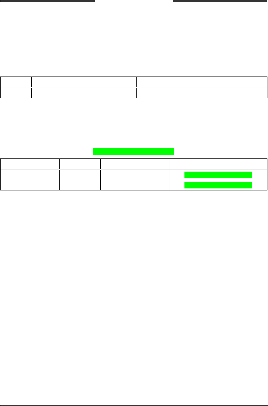
Table 1-1: NGT-2000/2500 General Description
MODEL/ P/N DESCRIPTION INTERFACES/FUNCTIONS
NGT-2000
9022500-10000
Support GPS, ADS-B IN/OUT, and
Wi-Fi.
• Maintenance Port
• Altitude data input
• Squawk code interception/comparator (If
optional control panel is used)
• Status indicator outputs (Required only
if CP-2500 is not used)
• Coverage indicator output (Required
only if CP-2500 is not used)
• Data Configuration Module
• RS-232 output to which an external Wi-
Fi adapter can be connected
• GPS Antenna
• UAT – L-Band Antenna
NGT-2500 *
9022500-10000
Supports GPS, ADS-B IN/OUT,
Wi-Fi, and interfaces with traffic
and weather displays.
• Maintenance Port
• Altitude data input
• Squawk code interception/comparator (If
optional control panel is used)
• Status indicator outputs (Required only
if CP-2500 is not used)
• Coverage indicator output (Required
only if CP-2500 is not used)
• Data Configuration Module
• RS-232 output to which an external Wi-
Fi adapter can be connected
• GPS Antenna
• UAT – L-Band Antenna
• ARINC 429 output to drive a Traffic
Display terminal. (STIF or DTIF)
• RS-422 output to drive standard RS-422
displays
* Note: The NGT-2500 configuration requires a product key that is set up during installation. See paragraph 1.3.1.
DRAFT 3-2

NGT-2000/2500
Installation Manual
Page 1-2 General Information 0040-17011-01
Prel-2014 Revision A
1.2 FUNCTIONAL DESCRIPTION
The Multilink Surveillance System (MSS) is a family of products that provide varying levels of
functionality over a range of General Aviation (GA) aircraft (based on aircraft performance and owner
preference). The levels of functionality that can be provided across the products are as follows:
• Automatic Dependant Surveillance – Broadcast (ADS-B) Out transmitted over 978 MHz Universal
Access Transceiver (UAT) link.
• Enhanced Visual Acquisition (EVAcq) using traffic information from ADS-B In received via a UAT
link.
• Flight Information Service – Broadcast (FIS-B) using received data via UAT link.
• Interfaces with RS-232 compatible transponders for the input of the Mode A squawk Code and mode
of operation from the aircraft’s existing Air Traffic Control Radar Beacon System (ATCRBS)
transponder or through a dedicated MODE A control panel interface.
The NGT-2000/25000 has an internal GPS receiver that provides own aircraft information (position,
velocity, track (or ground track), etc.) for ADS-B Out messages and traffic display.
This GPS is not intended as a position source to a navigation management unit that outputs deviation
commands keyed to a desired flight path.
When permitted the transmission of own ship identification can be inhibited using the Anonymous Mode
function provided by the CP-2500 control panel. This may only be accomplished when VFR Mode is active.
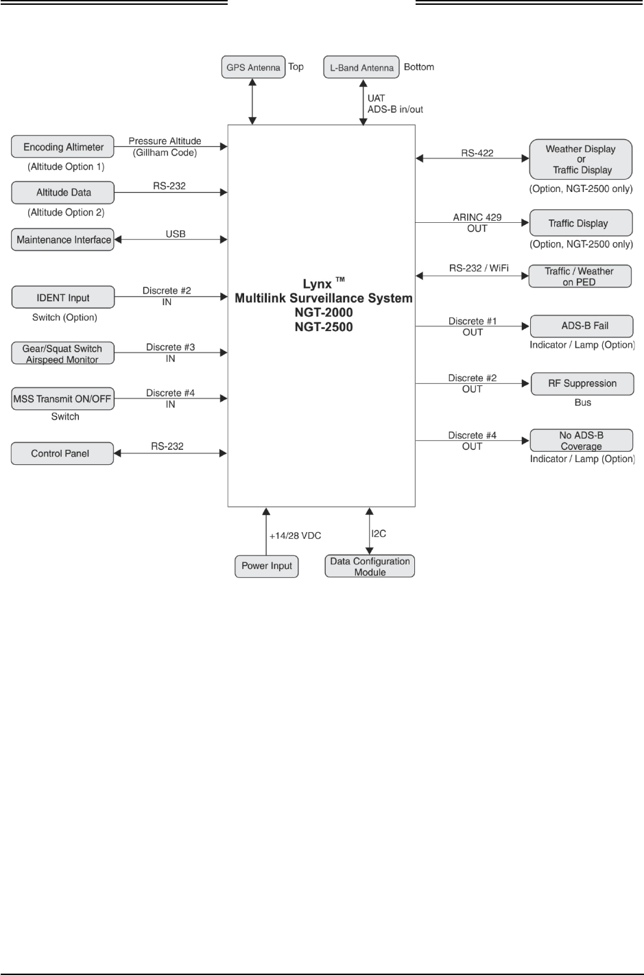
See Figure 1-1 for an overview of the unit’s system interface. The following paragraphs provide an
overview of each of these functions.
1.2.1 Enhanced Visual Acquisition Functional Overview
The Enhanced Visual Acquisition (EVAcq) function provides flight crews with a display of nearby traffic
relative to own aircraft (Cockpit Display of Traffic Information – Traffic Display) to assist with visually
acquiring traffic out the window and provide traffic situational awareness beyond visual range. Each
displayed traffic symbol conveys aircraft position, vertical trend and altitude information. Traffic on the
display (i.e. CDTI displays or some PED applications) can be selected by the flight crew to obtain
additional traffic information such as flight identification and ground speed.
The EVAcq function can display traffic on either an integrated traffic display (STIF or DTIF) or an
external traffic display (i.e. PED).
Data received via a UAT link (Ground stations- when in a coverage area) is the ADS-B, ADS-R
Rebroadcast, and TIS-B Traffic Information Service – Broadcast (traffic information used by EVAcq).
ADS-B (UAT) traffic can be received directly from another UAT equipped aircraft. TIS-B traffic and
ADS-R traffic can only be received when in the coverage area of an ADS-B ground station.
1.2.2 GPS Functional Overview
The GPS function utilizes signals from Global Positioning System (GPS) satellite constellation and
Satellite-Based Augmentation Systems (SBAS) such as the USA Wide Area Augmentation System
(WAAS), European EGNOS, Indian GAGAN and the Japanese MSAS. Currently it supports WAAS and
WAAS compatible SBAS systems.
The GPS signals are down converted to a low Intermediate Frequency, which is then processed by a micro
controller. This internal GPS function provides position, velocity, time and integrity (NIC, NAC etc)
information to the ADS-B functions and is ADS-B rule compliant with the position resource requirements
of AC20-165A.
DRAFT 3-2
NGT-2000/2500
Installation Manual
0040-17011-01 General Information Page 1-3
Revision A Prel-2014
Figure 1-1: System Interface Overview
1.2.3 FIS-B Functional Overview
The Flight Information Services - Broadcast (FIS-B) function provides pilots with a cockpit display of
certain aviation weather and aeronautical information for awareness of own aircraft location with respect
to reported weather, including hazardous meteorological conditions (RADAR/AIRMETS/SIGMETS/
NOTAMS/ METARS, etc) and NAS status (TFRs) indicators.
FIS-B is advisory information only and is intended to enhance pilot decision-making during strategic
flight planning. FIS-B augments traditional sources of this information such as ATC and Flight Service
Station (FSS). FIS-B information is provided over the ADS-B Services network on the 978 MHz UAT
link when in ground station coverage.
DRAFT 3-2

NGT-2000/2500
Installation Manual
Page 1-4 General Information 0040-17011-01
Prel-2014 Revision A
1.2.4 ADS-B Out Functional Overview
The ADS-B Out function supports the transmission of Automatic Dependant Surveillance – Broadcast
(ADS-B) Out on a 978 MHz UAT link. The ADS-B Out data contains information about own aircraft
such as aircraft position, velocity, direction, etc. The ADS-B function receives aircraft data to output from
an internal GPS receiver.
Pressure altitude is received from existing altitude source, and control functions such as squawk codes,
Ident, and operational mode (e.g. Mode "A", Mode "C", etc.) is obtained from an approved control panel.
1.2.5 Multiple Source Inputs Operation
The NGT-2000/2500 has multiple Altitude source connections available. There is an option, through the
configuration module, of connecting RS-232 serial altitude source or Grey code altitude source, however
only one source can be connected at a time. The altitude source must be the same source used for the
mode "C" transponder if so equipped.
1.2.6 Discrete Inputs and Outputs
The MSS has discrete inputs and outputs that can be used in place of some functions that are not available
to equipment that is compatible with the MSS. See Figure 1-1.
• The Squat/Airspeed Monitor switch signals the On Ground status to the MSS via a squat switch, gear
switch, or external airspeed sensor input.
• The IDENT command activates SPI and transmits an ident pulse. An ident pulse highlights the
aircraft’s symbol on the ATC’s radar screen and is identified on the control panel when active.
• The MSS Transmit ON/OFF function is used to stop ADS-B out transmission. Setting this discrete
OFF turns the ADS-B Failure lamp ON.
• ADS-B Failure Lamp indicates that the MSS is unable to transmit due to the following:
1. If the indicator lamp is flashing at a slow rate, then the aircraft position information is invalid or
has failed. GPS may be acquiring signal in which case when it does the lamp will stop flashing.
Flashing will last only 2 minutes before the lamp stays ON.
2. If the indicator lamp is flashing at a fast rate then a Code mismatch (squawk code) has been
detected. The squawk code must be re-entered correctly (matching the transponder) using the
control panel.
3. If the lamp is ON, then the ADS-B has failed or the MSS Transmit ON/OFF switch is set OFF.
• No ADS-B Coverage lamp is used to indicate that the unit is not receiving an ADS-B ground station
signal.
DRAFT 3-2

NGT-2000/2500
Installation Manual
0040-17011-01 General Information Page 1-5
Revision A Prel-2014
1.2.7 Transponder Interface
• If the aircraft is equipped with a compatible transponder that has an RS-232 control panel output
(e.g. GTX-327), then the NGT-2000/2500 can receive mode control and the squawk code directly
from that transponder.
• If the aircraft is equipped with a non-compatible transponder, then the aircraft needs a CP-2500
Control Panel installed. With the CP-2500 the NGT-2000/2500 can wirelessly intercept the Mode A
squawk Code from the aircraft’s existing ATCRBS transponder and conduct a cross check between
the transponder broadcast value and the setting of the NGT-2000/2500 Mode A control panel setting
to ensure the consistency in selected Mode A squawk code selections.
If the code entered from the control panel does not match the Mode A response from the
transponder, then a Mode A mismatch failure message is set in the control panel and the aircraft call
sign is used in the UAT Message transmissions. Pilot action is required to assure that the codes set
into the transponder and the CP-2500 always match.
If a CP-2500 is not installed, then the ADS-B Failure indicator lamp will flash ON/OFF at a fast rate
indicating a Mode A mismatch failure. Pilot action is required to correct the condition.
• If the aircraft is not equipped with transponder, then the control panel may be configured to provide
squawk code data and mode control (i.e. standby, on, ALT modes).
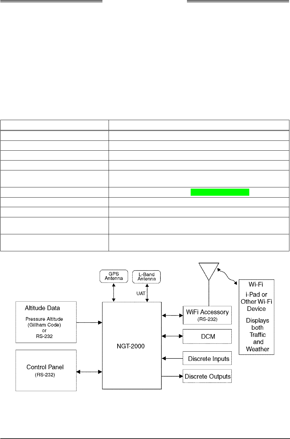
1.3 EQUIPMENT DESCRIPTIONS
The NGT-2000 and NGT-2500 are equipped with a main sub-D connector (J2) and RF connectors (UAT
and GPS). A USB port (J1) is available to establish communication between the NGT-2000 and a
maintenance computer for installation and maintenance activities. Both units provide ADS-B In, ADS-B
Out, ADS-R, TIS-B Traffic, FIS-B weather, NOTAMS, and TFRs functionality. Figure 1-2 shows the
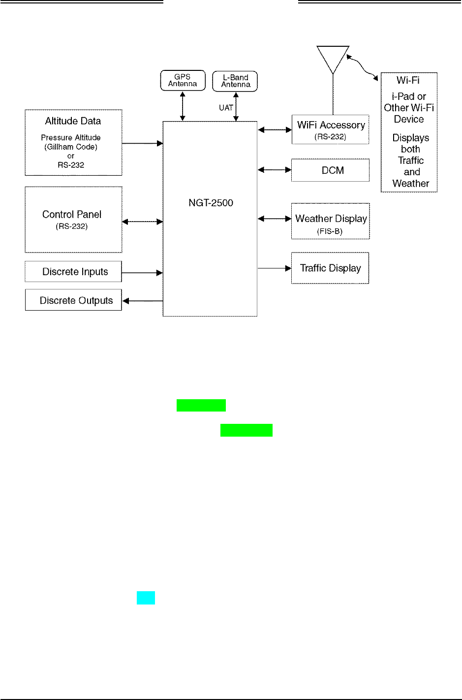
NGT-2000 system interface. Figure 1-3 shows the NGT-2500 system interface.
• The NGT-2000 and NGT-2500 both provide an RS-232 output that can be used to display UAT
ADS-B traffic as well as FIS-B weather information when an external WiFi accessory is connected
to transmit the received weather data to a commercial PED (i.e. Personal Electronic Device).
• The NGT-2500 outputs ARINC 429 to interface with an onboard cockpit display of traffic
information display (STIF or DTIF) for the display of own ship (DTIF only) and traffic information.
• The NGT-2500 can interface with a RS-422 data bus output that may be interfaced to a display to
provide weather or traffic information.
The UAT ADS-B In function supports the reception of ADS-B on a 978 MHz UAT link. The ADS-B In
data contains information about proximate aircraft such as aircraft position, velocity, direction, etc. and
also receives FIS-B data and ADS-R and TIS-B data from ground stations.
The ADS-B Out function is used to broadcast (without interrogation) periodic information about the
aircraft that includes aircraft identification, position, altitude, velocity and other aircraft status
information.
DRAFT 3-2
NGT-2000/2500
Installation Manual
Page 1-6 General Information 0040-17011-01
Prel-2014 Revision A
The FIS-B function provides pilots and flight crews with a cockpit display of certain aviation weather and
aeronautical information for awareness of own aircraft location with respect to reported weather,
including hazardous meteorological conditions and NAS status indicators. FIS-B is advisory information
only and is intended to enhance pilot decision-making during strategic flight planning. FIS-B augments
traditional sources of this information such as ATC, Flight Service Station (FSS), and Aircraft
Operational Communications Center. FIS-B information is provided over the ADS-B Services network on
the 978 MHz UAT link.
Table 1-2 describes the available built-in interfaces. Refer to Appendix A for detailed information on the
interface options. The traffic and weather display interfaces are only available to the NGT-2500 system
and requires a system product key to activate. See paragraph 1.3.1.
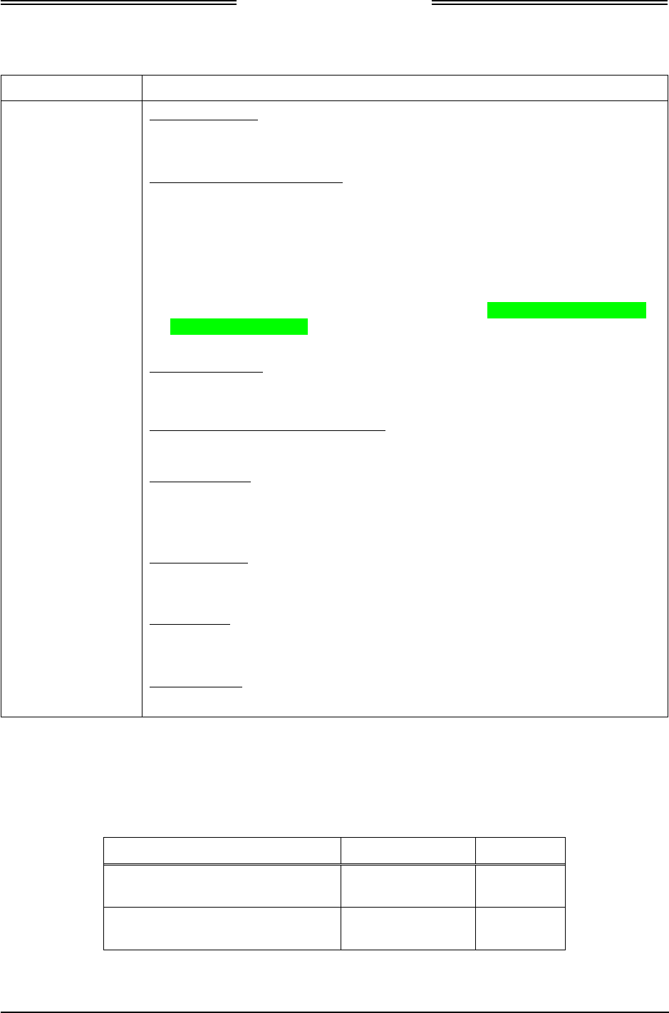
Table 1-2: MSS Built-in Interfaces
Interface (no.) Functionality
ARINC 429 Output (1) (NGT-2500 only) Transmit to a display(STIF or DTIF)
RS-232 Input / Output (2) Control Panel port and Wi-Fi accessory port
RS-232 Input (1) Altitude Encoder port
RS-422 Input / Output (1) (NGT-2500 only) Communicate with an external display port
Discrete Inputs (14) Receive Gillham Altitude Encoder, IDENT Command, In Air /
On Ground status, MSS Transmit ON/OFF
Discrete Output (4) Transmit ADS-B Failure and No ADS-B Coverage.
RF Suppression Input / Output (1) Provides on aircraft suppression of the L-band equipment
I2C Port (1) Configuration Module
GPS Antenna Port Connect to a top mount antenna providing GPS data to support
ADS-B functionality
L-Band Antenna Port Connects to the bottom mount antenna. Provides UAT 978
MHz input and output to support ADS-B functionality.
Figure 1-2: NGT-2000 Block Diagram
DRAFT 3-2
NGT-2000/2500
Installation Manual
0040-17011-01 General Information Page 1-7
Revision A Prel-2014
Figure 1-3: NGT-2500 Block Diagram
1.3.1 System Product Key
A product key is required if installing the NGT-2500 option. The product Key is a 10 digit code that is
used during installation and requires the NGT MAT to configure the unit. The product key is typically
shipped with the unit. If the product key is not included, contact L-3 Avionics Systems Customer Service
to obtain the code. Be sure to have the Mode-S ID (e.g. ICAO) available for the service representative.
1.3.2 Data Configuration Module
The NGT-2000/2500 interfaces to a Data Configuration Module (DCM), part number 9230-17003-01 for
the storage of configuration data. The DCM is permanently installed in the wire harness and interfaces to
NGT-2000/2500 via a 4 wire interface from the DCM.
The configuration settings are stored in the unit’s non-volatile memory and are entered via commands
sent over the maintenance interface to configure such items as:
• I/O port allocation (e.g. which external equipment is tied to RS-232 and ARINC 429 Tx lines, etc.).
• Aircraft Configuration Data (specific aircraft ID information, 24 bit unique ICAO address, make,
model, registration, etc).
• Mode A Control Panel type (RS-422).
• Optional equipment installation settings.
If the configuration data in the unit is not self-consistent (contains contradictory settings), the DCM is faulty
or the DCM has corrupted data, the unit will annunciate a failed state and not transmit ADS-B position
reports. A change in configuration data or replacement DCM will be needed to restore the unit to operation.
DRAFT 3-2

NGT-2000/2500
Installation Manual
Page 1-8 General Information 0040-17011-01
Prel-2014 Revision A
1.4 SPECIFICATIONS
Table 1-3: Specifications for the NGT-2000 and NGT-2500
PART NUMBER: 9022500-10000
CERTIFICATION: TSO-C145c, C154c, C157a, C195a.
For more information on TSO information, refer to paragraph 1.5.
Listed are current certifications at time of publication, contact Field
Service Engineering for latest certification information.
ADVISORY CIRCULARS: AC 20-165A (ADS-B Out), AC-20-172A (ADS-B In), AC20-138D
(GPS), AC20-149A (FIS-B)
RTCA COMPLIANCE: Environmental Category: DO-160G (See Environmental
Qualification Form in Appendix B.)
Software Category: DO-178B, Level C
Hardware Category: DO-254 Level C
Other: DO-229D, DO-282B, DO-317A, DO-267A, FAR 91.227
SIZE: Height 2.8 inch [71.6 mm]
Width 4.5 inch [114 mm]
Length 5.7 inch [145 mm]
WEIGHT: 1.0 lb nominal
CHASSIS GROUND: Bonding impedance between aircraft ground and the MSS Chassis
must be less than 2.5 milliohms.
POWER REQUIREMENTS: Main Power 14 Vdc/28 Vdc, 8.9 watts nominal, 10.1 watts MAX
ELECTRICAL CONNECTORS: • J2 [62 pin] Mates with P/N M24308/2-14 (TE connectivity) or
L-3AS P/N 9001640-002 with backshell P/N 3050-17000-01
(See installation kit P/N 9060-17250-01)
• J1 is a Mini-b USB connection (5 pin) Maintenance Port
• RF Connector (2): 5W5 Coax D-Sub
OPERATING TEMPERATURE: -45° to +70°C (-49° to 158°F)
STORAGE TEMPERATURE: -55° to +85°C (-67° to +185°F)
MAXIMUM ALTITUDE: Operating:18,000ft (5486 meters)
Tested: 25,000 ft (7620 meters)
NOTE: the unit is tested at 25,000 ft, however the UAT device is
restricted to 18,000 ft for transmit.
SCHEDULED MAINTENANCE: None
SERVICE LIFE: The unit has unlimited service life.
REPAIRABILITY: Repairs performed at the FAA certificated Repair Station co-located
at the OEM (equipment) facility.
DRAFT 3-2

NGT-2000/2500
Installation Manual
0040-17011-01 General Information Page 1-9
Revision A Prel-2014
Table 1-4: Specifications for Configuration Module
PART NUMBER: 9230-17003-01
CERTIFICATION: USA (FAA):
TSO-C145c, C154c, C157a, C195a. Configuration module installed
with NGT-2000/2500
For more information on TSO information, refer to paragraph 1.5.
Listed are current authorizations at time of publication, contact Field
Service Engineering for latest certification information
RTCA COMPLIANCE: Environmental Category: DO-160F
See Environmental Qualification Form in Appendix B.
WEIGHT: Negligible
SIZE: Length: 6 inches (includes wires)
POWER REQUIREMENTS: 3.3 Vdc (regulated via J1 connector)
INTERFACE (S): I2C serial interface
OPERATING TEMPERATURE: -40° to +70°C (-40° to +158°F)
STORAGE TEMPERATURE: -55° to +85°C (-67° to +185°F)
MAXIMUM ALTITUDE: 55,000 ft (installation environment)
SCHEDULED
MAINTENENACE: None.
SERVICE LIFE: Unlimited.
REPAIRABILITY: Replacement only.
DRAFT 3-2

NGT-2000/2500
Installation Manual
Page 1-10 General Information 0040-17011-01
Prel-2014 Revision A
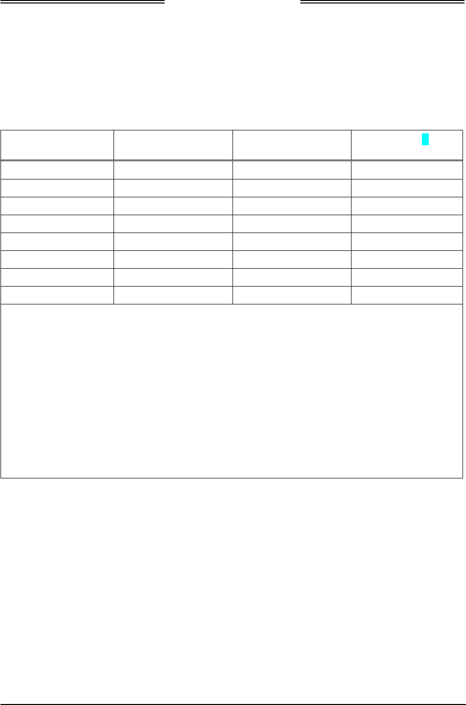
1.5 TSO INFORMATION
TSO NO. FUNCTION TSO TITLE CONFIGURATION
TSO-C157a FIS-B Display
(RS-422)
Aircraft Flight Information Services-
Broadcast (FIS-B) Data Link Systems and
Equipment
NGT-2500
TSO-C145c GPS SBAS
Output
Airborne Navigation Sensors Using The
Global Positioning System Augmented By
The Satellite Based Augmentation System
NGT-2000/2500
TSO-C195a ASSAP and
ARINC 735
based traffic
display Support
Avionics Supporting Automatic Dependent
Surveillance – Broadcast (ADS-B) Aircraft
Surveillance Applications (ASA)
NGT-2500
TSO-C154c UAT-IN Universal Access Transceiver (UAT)
Automatic Dependent Surveillance-
Broadcast (ADS-B) Equipment Operating
on Frequency of 978 MHz
NGT-2000/2500
TSO-C154c UAT-OUT Universal Access Transceiver (UAT)
Automatic Dependent Surveillance-
Broadcast (ADS-B) Equipment Operating
on Frequency of 978 MHz
NGT-2000/2500
1.5.1 TSO Markings
The following information summarizes the TSO application for the NGT-2000, NGT-2500, and the
installed configuration module.
TSO NO. TSO MARKING TSO TITLE
TSO-C145c TSO-C145c Class Beta 1 Airborne Navigation Sensors Using The Global
Positioning System Augmented By The Satellite Based
Augmentation System
TSO-C154c TSO-C154c Class A1S Universal Access Transceiver (UAT) Automatic
Dependent Surveillance-Broadcast (ADS-B) Equipment
Operating on Frequency of 978 MHz
TSO-C157a TSO-C157a Class 2
Incomplete Aircraft Flight Information Services-Broadcast (FIS-B)
Data Link Systems and Equipment
TSO-C195a TSO-C195a Class C1 Avionics Supporting Automatic Dependent Surveillance
– Broadcast (ADS-B) Aircraft Surveillance Applications
(ASA)
DRAFT 3-2

NGT-2000/2500
Installation Manual
0040-17011-01 General Information Page 1-11
Revision A Prel-2014
1.5.2 TSO Deviations from Minimum Performance Standards
The following information lists the TSOs for the unit that requires a deviation to Minimum Performance
Standards (MPS) that are called out in the TSO and provides the justification for the deviation.
TSO NO. DEVIATION
TSOC-145c TSO requires use of DO-160E for environmental qualification testing; DO-160G was
used instead.
TSOC-145c
TSO-C154c
TSO-C157a
Per the guidance in FAA Order 8150.1c, the appliances are marked with the primary
TSO along with a reference to the Installation Manual for the other TSO information
(other applicable TSOAs, deviations, etc.).
TSOC-145c
TSO-C154c
TSO-C157a
The NGT-2500 utilizes a Maintenance Computer (i.e., a “special tool”) as its primary
support tool required for installation and debug effort. All installations will require that
the Maintenance Computer be used to verify the software part number that is stored
electronically in the unit thereby ensuring the part has been installed in compliance to
the type design data. All software updates will also require that the Maintenance
Computer be used to verify the software part number that is stored electronically in the
unit thereby ensuring the part is in compliance to the type design data.
TSO-C154c The RF radiated emissions to exceed the Category L requirement for the RF radiated
emission limit in the following frequency bands:
• 1956 MHz ± 2.25MHz (2nd Transmitter harmonic) Exceeds Cat L by as much as 30dB
• 2934MHz ± 1MHz (3rd Transmitter harmonic) Exceeds Cat L by as much as 14dB
• 3912MHz ± 1MHz (4th Transmitter harmonic) Exceeds Cat L by as much as 15dB
• 4890Mhz ± 1MHz (5th Transmitter harmonic) Exceeds Cat L by as much as 8dB
• 5868Mhz ± 1MHz (6th Transmitter harmonic) Exceeds Cat L by as much as 3dB
Meets DO-282B spectrum reply bounds. There is limited average radiated power in the
deviation magnitudes due to the very low duty cycle. There are no defined aeronautical
safety related operations utilizing these frequencies. For this deviation, the NGT-2500
Installation Manual will direct the installer to specifically verify non-interference with
other avionic systems for these frequencies (See Installation Checkout section).
1.5.3 Non-TSO Functions
The NGT-2000 and NGT-2500 do not have any Non-TSO functions.
DRAFT 3-2
NGT-2000/2500
Installation Manual
Page 1-12 General Information 0040-17011-01
Prel-2014 Revision A
1.6 MODIFICATIONS
Modifications (MODS) to the NGT-2000/2500 are identified below and are identified by an entry on the
I.D tag on individual units.
Table 1-5: Hardware Modifications
MOD # EFFECTIVITY / COMPLIANCE DESCRIPTION
None
1.7 SOFTWARE REVISIONS
Software revisions and database versions are viewed using the MPC via the Maintenance Application
Tool. A list of current software revisions is identified below.
Table 1-6: Software Revisions
DESCRIPTION REVISION PART NUMBER COMPATIBLE NGT MAT
Composite Software 1.0 9021105-001 8010-17002-0001, Rev 1.0
Boot Loader 1.0 9021110-001 8010-17002-0001, Rev 1.0
1.8 INTERFACES
The electrical characteristics of all input and output signals are detailed in Appendix A.
DRAFT 3-2

NGT-2000/2500
Installation Manual
0040-17011-01 General Information Page 1-13
Revision A Prel-2014
1.9 EQUIPMENT REQUIRED NOT SUPPLIED
Use Table 1-7 to identify equipment required for installation, calibration, and testing.
NOTE
Equivalent tools, equipment and hardware may be used.
Table 1-7: Equipment List
ITEM DESCRIPTION
Cables and Wiring: The installer supplies all system wires and cables.
Mating Connector (P1)
• Wires are #22 AWG as noted on interconnect wiring diagram in section 2.
Use M22759 or equivalent wire and use M27500 or equivalent for twisted
shielded Tefzel wire for installation.
WiFi Accessory Connector
• 9-Pin Sub-D Connector, P/N M24308/2-1 or equivalent. Use M27500 or
equivalent for twisted shielded wire for installation as noted on interconnect
wiring diagram.
Antenna Cables
• L-Band and GPS Antenna
Require M17/128-RG400 or equivalent Coaxial Cable. Attenuation must not
exceed 1.5db per cable (including the connectors). Refer to Table 1-9.
NOTE
RG type coaxial cable insertion loss can vary significantly between
manufacturers. Refer to the cable manufacturer's specification sheet for
actual attenuation (insertion loss) for the cable being used.
Circuit Breaker: Installer is responsible for determining appropriate circuit breakers needed to
protect aircraft wiring. Manufacturer recommends the following:
• 1.0 Amp circuit breaker for the installations with 28Vdc input
• 1.5 Amp circuit breaker for the installations with 14Vdc input
If installing the NGT-2000/2500 with a CP-2500 Control Panel:
• 2.5 amp breaker (connected to same breaker as NGT-2000/2500
with 14Vdc input)
• 2.0 amp breaker (connected to same breaker as NGT-2000/2500
with 28Vdc input)
Consumables: Antenna Sealant
• For pressurized aircraft, use a sealant that meets the requirements of SAE
AMS-S-8802 such as Flamemaster® CS3204 class B. For non-pressurized
aircraft, use a non-corrosive sealant that meets the physical requirements of
MIL-A-46146 such as General Electric RTV162.
Surface Preparation
• Alodine® No. 1001 required for installation of the antenna.
DRAFT 3-2

NGT-2000/2500
Installation Manual
Page 1-14 General Information 0040-17011-01
Prel-2014 Revision A
Table 1-7: Equipment List
ITEM DESCRIPTION
Hardware: The following items are commercially available and is the responsibility of the
installer:
• Ring Terminals (For Grounding).
• Solder Sleeves.
• Cable tie/Tie wrap.
• Ground Braid (RAY-101-20.0/AA59569R36TXXXX or equivalent).
• Coaxial connectors.
• Status indicator lamps, placards (“fail lamp”).
• Fusion tape.
• No. 6 Mounting Screws, washers and nuts (mounting hardware).
Installation Tools: • Insertion/Extraction tool CIET-20HD.
• Crimp Tool: P/N: M22520/2-01.
• Positioner: P/N: M22520/2-08.
• Heating tool and reflector: PR-25 or PR-25D and HL1802E-ADAPT. (Tyco
Electronics) for solder sleeves.
Installation Kits: Installation Kits for the NGT-2000/2500 are a customer option and are ordered
separately. Refer to paragraph 1.9.1 for ordering information and a parts list.
Software: NGT Maintenance Application Tool (NGT MAT)
Tool used for diagnostics, set up configuration options, and software
downloading. The tool is only available to an Avionics Systems Authorized
Installer. Refer to paragraph 1.11 for details on how to obtain a copy or Contact
Avionics Systems Field Service for more information.
• P/N 8010-17002-0001
LynxMMS USB Driver
This driver is required for communication between the MPC and the WiFi
Accessory.
DRAFT 3-2
NGT-2000/2500
Installation Manual
0040-17011-01 General Information Page 1-15
Revision A Prel-2014
Table 1-7: Equipment List
ITEM DESCRIPTION
Test Equipment: Air Data Test Set
• Required to test altitude inputs.
Maintenance Computer (MPC)
• The MPC is a laptop computer used to operate the NGT Maintenance
Application Tool for system setup, post installation checkout and
troubleshooting.
The computer should be using Windows 7 as the operating system, 1.3 GHz
processor or greater and 512 MB or more of RAM. Other configurations may
operate normally, but they have not been tested.
The computer must also have an USB connection and the installation of the
LynxMSS USB driver.
Mini-b USB Cable
• Required if using the USB port to interface the MPC to the MSS.
DB9 F/F Standard Null Modem Cable
• Required to configure WiFi Accessory.
Flightline Tester
• IFR-6000 Ramp Test Set (with upgrade package Option #3 (1090) & #5
(UAT), Manufacturer: AEROFLEX.
GPS Generator
• GPSG-1000, Manufacturer: AEROFLEX.
Oscilloscope
• Required to verify NGT-2000/2500 suppression pulse (100 µs ±5µs, +28 V dc)
Milliohm Meter
Required to check installation bonding to aircraft structure.
1.9.1 Installation Kits
Ordering Installation Kits is a customer option. Refer to the following for ordering information:
Table 1-8: Installation Kit P/N 9060-17250-01
DESCRIPTION PART NUMBER QTY
Hood-Sub Shell Size 4 Alum. With
rotating JA
3050-17000-01 1
Connector D Sub Receptacle Hi
Density 62 Positions Crimps
9001640-002 1
DRAFT 3-2
NGT-2000/2500
Installation Manual
Page 1-16 General Information 0040-17011-01
Prel-2014 Revision A
1.9.2 Antenna Cables
Table 1-9 lists examples of the recommended antenna cable vendors and the type of cable to be used for
specific lengths of cable. Any cable meeting specifications is acceptable for the installation.
Table 1-9: Coaxial Cable Specifications
INSERTION LOSS
(DB/100FT) [1]
CARLISLE IT TYPE [2] MIL-C-17 TYPE [3] RG TYPE
18.5 N/A M17/128-RG400 RG-400
11.1 N/A M17/112-RG304 RG-304
9.2 N/A M17/127-RG393 RG-393
15.2 3C142B N/A N/A
9.2 311601 N/A N/A
7.5 311501 N/A N/A
5.8 311201 N/A N/A
3.8 310801 N/A N/A
[1] RG type coaxial cable insertion loss can vary significantly between manufacturers. The insertion
loss for RG type cables shown in this column is considered 'worst case'. Refer to the cable
manufacturer's specification sheet for actual attenuation (insertion loss) for the cable being
used.
[2] Supplier information (for reference only):
Carlisle IT
5300 W. Franklin Drive
Franklin, WI 53132
Tel: 800-327-9473
414-421-5300
Fax: 414-421-5301
www.carlisle.com
[3] Supplier information: See current issue of Qualified Products List QPL-17.
DRAFT 3-2

NGT-2000/2500
Installation Manual
0040-17011-01 General Information Page 1-17
Revision A Prel-2014
1.10 EQUIPMENT INTERFACES
The equipment listed here is compatible with the NGT-2000/2500. Equipment interfaces not listed in this
section can still be approved for installation, but must meet the requirements for the NGT-2000/2500.
1.10.1 GPS Antenna
All listed GPS antennas have TNC connector.
Table 1-10: Approved GPS Antennas
MANUFACTURER PART NUMBER
Aero Antenna AT575-326
Aero Antenna AT575-493
Aero Antenna AT575-343
Aero Antenna AT575-516
Aero Antenna AT135-3
Comant CI-2580-200
Comant CI-2728-410
Comant CI 428-200
Comant CI 429-200
Comant CI 429-410
Sensor Systems S67-1575-135
Sensor Systems S67-1575-137
Sensor Systems S67-1575-145
Sensor Systems S67-1575-160
1.10.2 UAT Antenna
Table 1-11: Approved UAT Antennas
MANUFACTURER PART NUMBER CONNECTOR TYPE
RAMI AV-74 BNC
Comant CI-105 BNC
Comant CI-105-11 TNC
DRAFT 3-2
NGT-2000/2500
Installation Manual
Page 1-18 General Information 0040-17011-01
Prel-2014 Revision A
1.10.3 Traffic Displays
Traffic information is output to a compatible traffic display from the NGT-2000/2500 using an ARINC
735B interface format. Possible traffic output format selections include Standard TCAS Intruder File
(STIF or TIF) and Display Traffic Information File (DTIF). The NGT-2000/2500 allows installed
configuration selection of STIF, DTIF, or both formats of output data via the ARINC 429 bus to the
traffic display. Displays not listed below can still be approved for installation, but must meet the
specifications required by the NGT-2000/2500.
Table 1-12: Approved Traffic Displays
MANUFACTURER MODEL, DESCRIPTION SW LEVEL
Garmin MX-20 (Standard traffic only) 5.7
Garmin GNS430 (Standard traffic only) TBD
Garmin G-500 (Standard traffic only) GDU-620 Version 6.11
FPGA and I/O Vers – 2.1
Garmin GTN-650 (Standard traffic only) 4.0 GPS SW Vers – 5.0
Garmin GMX-200 (Standard traffic only) TBD
1.10.4 Weather Display
Table 1-13: Approved FIS-B WX Displays
MANUFACTURER MODEL, DESCRIPTION SW LEVEL
Garmin MX-20 5.7
Garmin GMX-200 2.13
1.10.5 Control Panel
Table 1-14: Approved Control Panels
MANUFACTURER MODEL, DESCRIPTION SW LEVEL
L-3 Aviation Products CP-2500 FW Rev 07 and HW Rev 00
Garmin GTX-327 2.10
Garmin GTX-330 4.40
1.10.6 WIFI Accessory
Table 1-15: Approved RS-232 to WiFi Accessories
MANUFACTURER MODEL, DESCRIPTION
Roving Network RN370M
L-3 Avionics Systems TBD
DRAFT 3-2

NGT-2000/2500
Installation Manual
0040-17011-01 General Information Page 1-19
Revision A Prel-2014
1.10.7 PERSONAL ELECTRONIC DEVICE (PED) APPS
Table 1-16: Compatible APPS for PED
MANUFACTURER DESCRIPTION
Sky Radar
Wing X
1.11 SOFTWARE UPDATES
Software for the MSS can be obtained by either downloading from the L-3 Technical Publications
website or by receiving a compact disc.
1.11.1 Website Download
Use the following procedure to gain access to the L-3 Technical Publications website.
NOTE
For users of the L-3 RSA tokens a Risk-Based Authentication (RBA)
security system is currently being implemented that will eventually
eliminate the need for physical RSA tokens. Token accounts will not be
immediately converted. Continue to log in using the token until the
month in which it expires. Upon the expiration of the token, the account
will be converted to a RBA account. The expiration date is located on the
back of the RSA token.
First time users:
1. Go to https://www.l-3avionics.com/customer-support/technical-publications/.
2. On the Technical Publications page first time users must fill out the Secure Site Access Request and
return the form and supporting documentation to L-3 Avionics Systems by fax or email.
3. A User ID and temporary password will be sent by L-3 Avionics Systems after the documentation is
reviewed and accepted.
4. Go to https://www.avionicstechpubs.com.
5. Click on the Self-Service Console Link.
6. Enter the User ID and click the OK button.
7. Enter the temporary password and click the Log On button.
8. Create a new password and press the OK button.
9. Select and answer five security questions. Click the Submit button.
10. The Self-Service Console page is shown. Click the Log Off link in the upper right corner of the page
to complete the process. Go to the User s with site access.
DRAFT 3-2
NGT-2000/2500
Installation Manual
Page 1-20 General Information 0040-17011-01
Prel-2014 Revision A
Users with site access:
1. Go to https://www.avionicstechpubs.com.
2. Click on the red L-3 RBA link.
3. Enter User ID and click the OK button.
4. Answer security questions if requested. Click the Continue button.
5. Select the public or shared computer question. Click the Continue button.
6. After successful authentication the license agreement screen is shown. Click the I Agree button to be
taken to the home page.
Using the technical publications web site:
1. On the left side of the home page and select Search Documents. Enter “NGT-2000” or NGT-2500 in
the basic search field.
2. The search results provide a list of available publications and software for the NGT-2000 or
NGT2500.
3. Click on the “details” for the document you want to subscribe too.
4. Click on the “Subscribe to this document”. A zip file will download to your computer. (Note – This
download is only required one time. Afterwards any publication file may be downloaded on its own
from My Subscriptions.)
If you do not see the “Subscribe to this document” option, then access to this document is restricted.
Contact the Manuals Administrator at avionics.techpubs@l-3com.com for subscription access.
Software Revisions and Tools can also be obtained. A software notice document is used to identify
the specific software and has restricted access beyond what is required for the publication. Contact
the Manuals Administrator at avionics.techpubs@l-3com.com for access. The software notices for
the MSS are listed in Table 1-17:
Table 1-17: List of Service Notices
SERVICE NOTICE ID DESCRIPTION
8010-17002-0001_Rel-1.0 NGT Maintenance Application Tool (NGT MAT)
Tool used for diagnostics, set up configuration
options, and software downloading.
DRAFT 3-2

NGT-2000/2500
Installation Manual
0040-17011-01 General Information Page 1-21
Revision A Prel-2014
1.11.2 Compact Disc
The System Software Compact Disk (CD) contains executable files and instructions to update the MSS
software. The contents of the CD are listed in Table 1-17.
The system software is transferred to the MSS using a maintenance computer. Refer to the maintenance
section for loading and validation instructions.
Table 1-18: Software CD Part Number and Contents
PART NUMBER RELEASE CONTENTS
9230-TBD-0001 1.0 1. Software Label Readme
2. Composite Software, 9021105-001, Rev 1.0
3. Boot Loader, 9021110-001, Rev 1.0
4. NGT Maintenance Application Tool, 8010-17002-0001 Rev 1.0
1.12 INSTALLATION APPROVAL AND LIMITATIONS
1. The conditions and tests required for TSO approvals of this article are minimum performance
standards. It is the responsibility of those desiring to install this article either on or within a specific
type or class of aircraft to determine the suitability of the installation. The article may be installed
only if further evaluation by the applicant documents an acceptable installation and is approved by
the Administrator.
2. It is the installer’s responsibility to ensure the ADS-B Out system is compliant with AC 20-165A.
3. The MSS is not approved for installations with SATCOM-equipped airplanes.
4. The MSS is not approved for use with a diplexer.
5. Per DO-260B 2.2.8.5.1, the MSS installation is considered non-precision. Meaning that the
transmission requirement of the MSS does not include the use of GPS Time Mark for the potential
extrapolating of position for transmission.
DRAFT 3-2

NGT-2000/2500
Installation Manual
Page 1-22 General Information 0040-17011-01
Prel-2014 Revision A
This page intentionally left blank
DRAFT 3-2

NGT-2000/2500
Installation Manual
0040-17011-01 Installation Page 2-1
Revision A Prel-2014
Section 2
Installation
2.1 INTRODUCTION
This section provides installation information for the NGT-2000/2500 Multilink Surveillance System.
Installation must be made by qualified personnel, in conformance with applicable government
regulations. The information furnished is for convenience only.
Tolerances (unless otherwise indicated):
ANGLES ARE ± 0.5°
0.00 TWO PLACE DECIMALS ARE ± 0.02
0.000 THREE PLACE DECIMALS ARE ± 0.010
2.2 UNPACKING AND INSPECTING
Carefully unpack the unit and note any damage to shipping containers or equipment. Visually inspect
each component for evidence of damage. Compare the equipment received with that noted on the packing
list. Report immediately any missing items or evidence of damage to the carrier making the delivery. To
justify a claim, retain the original shipping container and all packing materials.
Every effort should be made to retain the original shipping containers for storage. If the original
containers are not available, a separate cardboard container should be prepared that is large enough to
accommodate sufficient packing material to prevent movement.
2.2.1 Transport and Storage Considerations
Transport of the NGT-2000/2500 should be done in accordance with standard procedures, i.e. hand
carried or transported in the original container. The container limits the shock to the unit at a maximum
of 20g’s when dropped from a distance of 36 inches (0.91 meters).
Storage of avionics equipment must be consistent with industry standards for avionics equipment and
performs satisfactorily after periods of storage up to 24 months. The ambient temperature of the storage
area should not fall below -55° C (-65° F) or rise above +85° C (+185° F).
DRAFT 3-2

NGT-2000/2500
Installation Manual
Page 2-2 Installation 0040-17011-01
Prel-2014 Revision A
2.3 INSTALLATION PROCEDURES
1. The installer must take the following into consideration prior to installation.
• The installer must obtain installation approval (i.e. Supplemental Type Certification).
• Follow the acceptable avionics installation practices in FAA Advisory Circulars AC 43.13-1B
and AC 43.13-2B or later revision of these documents.
• Installers are responsible for obtaining installation hardware (i.e. screws, supporting plates, etc).
Installation kits are available for purchase. Refer to the Equipment Required Not Supplied
Paragraph in the general information section.
• It is recommended that the aircraft battery be disconnected before performing installation
procedure.
• GPS and L-band antenna cables should be clearly labeled to prevent inadvertently installing on
the wrong connector.
• Tighten all screws to snug (i.e. only such torque that can be applied by hand) unless specific
torque instructions are given.
• After installation, refer to the Installation Checkout section for calibration, power-up and
ground testing procedures.
2. Electrical equipment chassis, shield/ground terminations, antennas, supporting brackets, and racks
must be electrically bonded to the aircraft's main structure (metallic aircraft) or instrument panel
(composite aircraft). Compliance of the electrical bonding should be verified by inspection using a
calibrated milliohm meter. An equivalent OEM procedure may also be substituted.
• The electrical bond should achieve direct current (DC) resistance less than or equal to 2.5 m to
structure local to where the equipment is mounted for metallic aircraft or tube and fabric
aircraft.
• The electrical bond should achieve direct current (DC) resistance less than or equal to 5.0 m to
the instrument panel for composite aircraft.
The antenna ground plane must be electrically bonded to the antenna baseplate. Do not remove paint
on outer skin of aircraft under the footprint of the antenna baseplate unless necessary to meet
bonding requirements. Refer to antenna manufacturer's installation instructions.
2.3.1 Location
The NGT-2000/2500 provides flight information. When locating the unit in the aircraft take the following
into consideration.
1. The unit should be accessible for inspection, maintenance, removal, free from excessive vibration or
heat and located in a clean and dry area.
2. The wiring cable should not run adjacent to heaters, engine exhaust, or heat sources.
3. Ensure the space requirements for the unit is acceptable at the location area being considered. Refer
to Figure 2-1 for dimensional requirements.
• The installer is advised to consider the space requirements (2-3 inches) needed for the connector
backshell and the cable bend radius.
4. Unit to be mounted firmly to the airframe using number 4 pan head machine screws.
5. The chassis of the unit must be properly bonded to the Ground. The chassis of the unit itself is
conductive and acts as a ground.
DRAFT 3-2
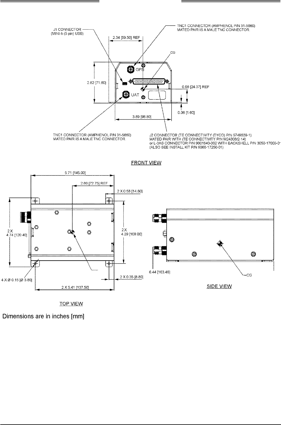
NGT-2000/2500
Installation Manual
0040-17011-01 Installation Page 2-3
Revision A Prel-2014
Figure 2-1: Outline Dimensions for NGT-2000/2500
DRAFT 3-2

NGT-2000/2500
Installation Manual
Page 2-4 Installation 0040-17011-01
Prel-2014 Revision A
2.3.1.1 Electrical Connections
1. The installer must take the following into consideration before installation.
• Use of any wire or cable not meeting specification voids all warranties.
• The installer is responsible for supplying wires, cables and connectors.
• Wire-marking identification is at the discretion of the installer.
• All wiring must be in accordance with industry-accepted methods, techniques, and practices.
• Refer to paragraph 1 for details on shielded cable preparation.
• Refer to Appendix A for signal name and cable characteristics prior to wiring installation.
• The length and routing of the external cables must be carefully studied and planned before
attempting installation of the equipment.
• The wiring harness should not run adjacent to heaters, engine exhaust, and heat sources or be
located near fuel lines, high electrical capacity lines, flight control cables, and protected areas of
the aircraft or be exposed to wire chafing.
• Avoid sharp bends while routing the cables.
• Cable runs should be as short as practical. Grounded pigtails must not exceed 3 inches in length.
Terminate shields in the backshell of the mating connector (at P1).
• All wires shall be 22 AWG. Use M22759 or equivalent wire and Tefzel Wire M27500 or
equivalent for twisted shielded wired for installation.
• Installer is responsible for determining appropriate circuit breakers needed to protect aircraft
wiring. Manufacturer recommends the following:
o 1.0 Amp circuit breaker for the installations with 14Vdc input
o 0.5 Amp circuit breaker for the installations with 28Vdc input
If installing the NGT-2000/2500 with a CP-2500 Control Panel:
o 2.0 amp breaker (connected to same breaker as NGT-2000/2500 with 14Vdc input)
o 1.5 amp breaker (connected to same breaker as NGT-2000/2500 with 28Vdc input)
• The configuration module is permanently attached to the mating connector during wire
installation and must be covered by the tinned copper braided shield as shown in xxxx. Refer to
paragraph 1 for details.
2. Refer to Figure 2-2 for an Interconnect Wiring Diagram. Refer to Figure 2-2 for interconnect wiring
diagrams for optional LRU installations. Refer to Appendix A for option equipment wiring
diagrams.
3. The P2 mating connector is a TE Connectivity P/N M24308/2-14 or an L-3 P/N 9001640-002 with
Backshell P/N 3050-17000-01 (Also See Install Kit P/N 9060-17250-01) or equivalent. Refer to
Figure 2-3 for pin locations and assignments. Refer to General Information Section- Equipment and
Materials required for Installation for connector installation tools.
4. The GPS and UAT connections (TNC1 Amphenol P/N 31-5660) require a male TNC mating
connector.
5. The WiFi interface should configure the WiFi Accessory prior to installation. Refer to the
Installation Checkout section (para. 3.3) for details.
6. It is recommended that the installer perform the following wiring checks during installation:
• Check all wiring point-to-point for continuity before connecting components.
• Ensure voltages are not applied to signal wires.
• Inspect cables for correct connection.
DRAFT 3-2
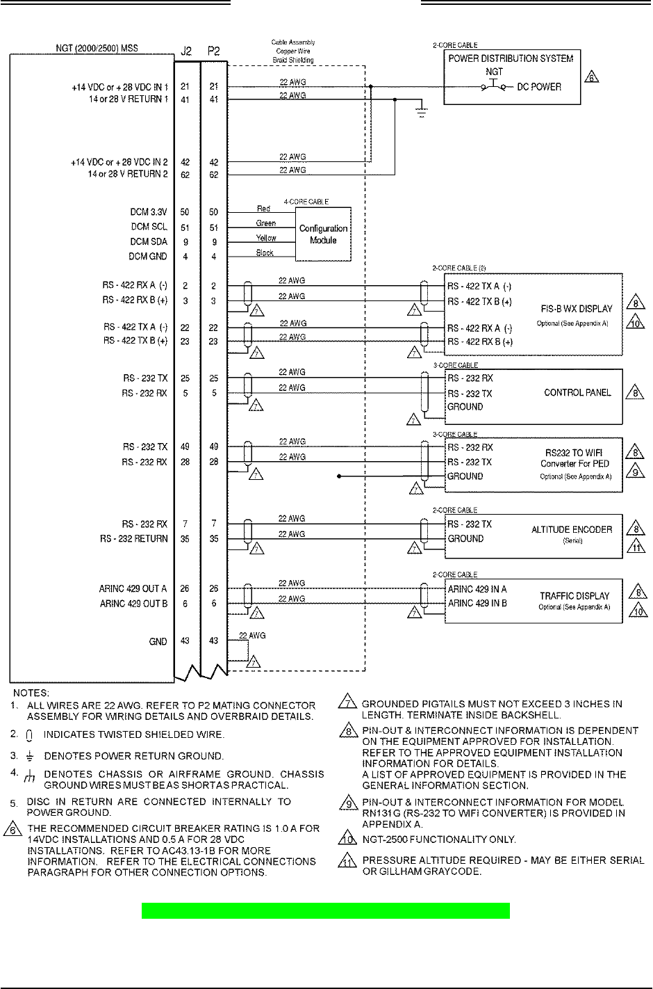
NGT-2000/2500
Installation Manual
0040-17011-01 Installation Page 2-5
Revision A Prel-2014
Figure 2-2: NGT-2000/2500 Interconnect Wiring Diagram
(Sheet 1 of 2)
DRAFT 3-2
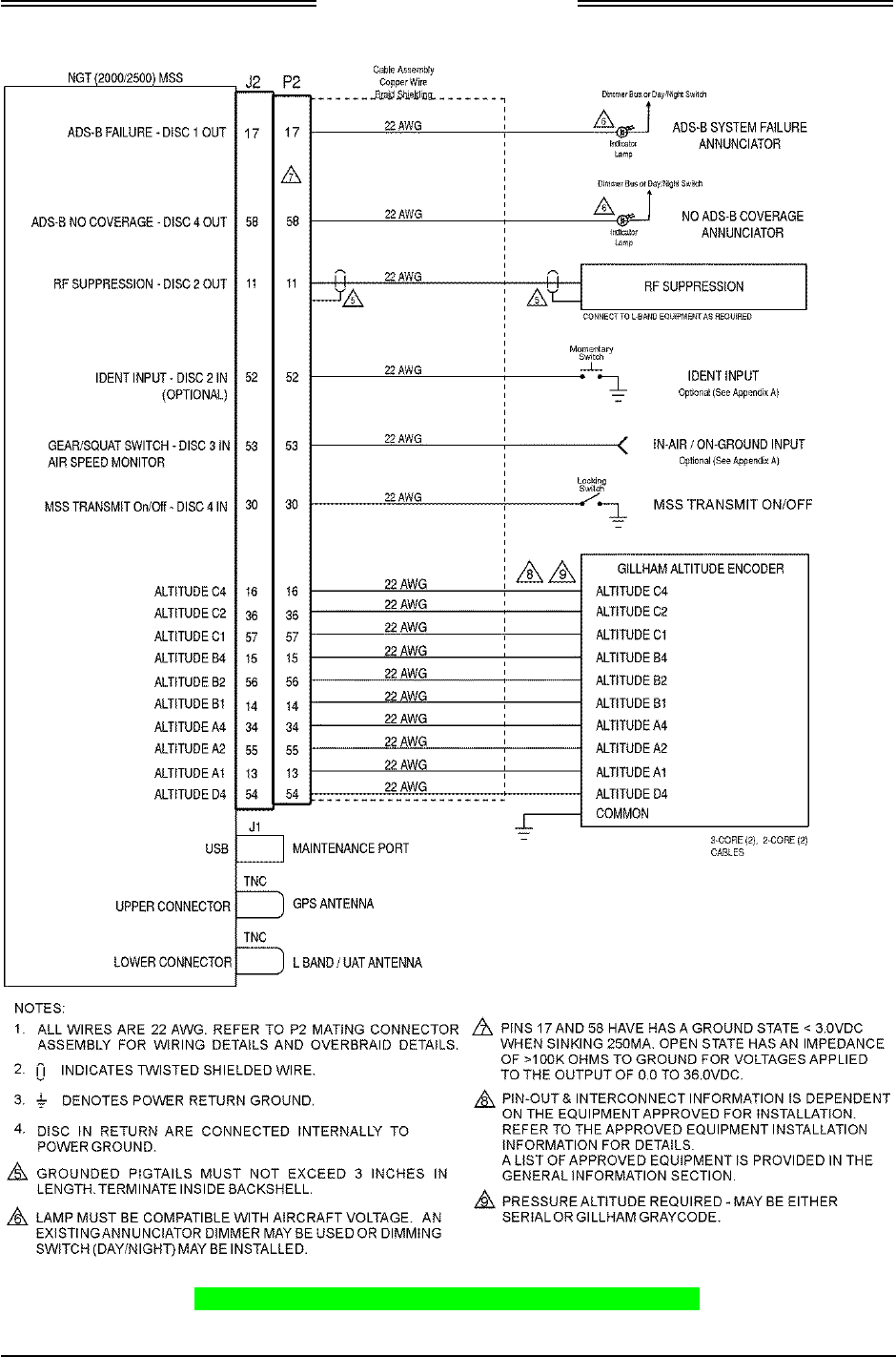
NGT-2000/2500
Installation Manual
Page 2-6 Installation 0040-17011-01
Prel-2014 Revision A
Figure 2-2: NGT-2000/2500 Interconnect Wiring Diagram
(Sheet 2 of 2)
DRAFT 3-2
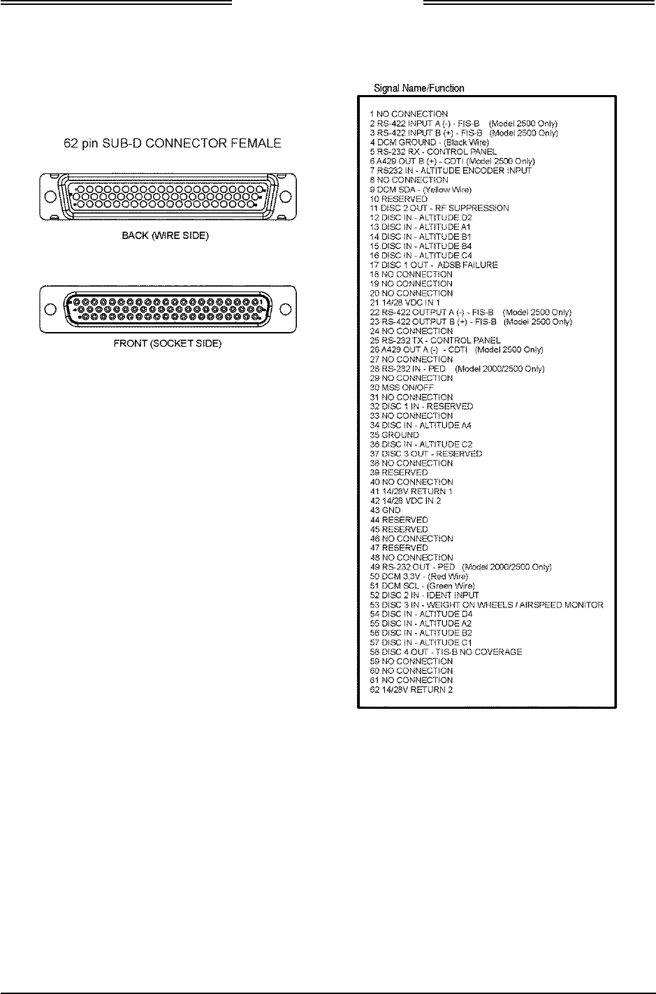
NGT-2000/2500
Installation Manual
0040-17011-01 Installation Page 2-7
Revision A Prel-2014
Figure 2-3: Mating Connector (P2) and Pin Assignments
DRAFT 3-2
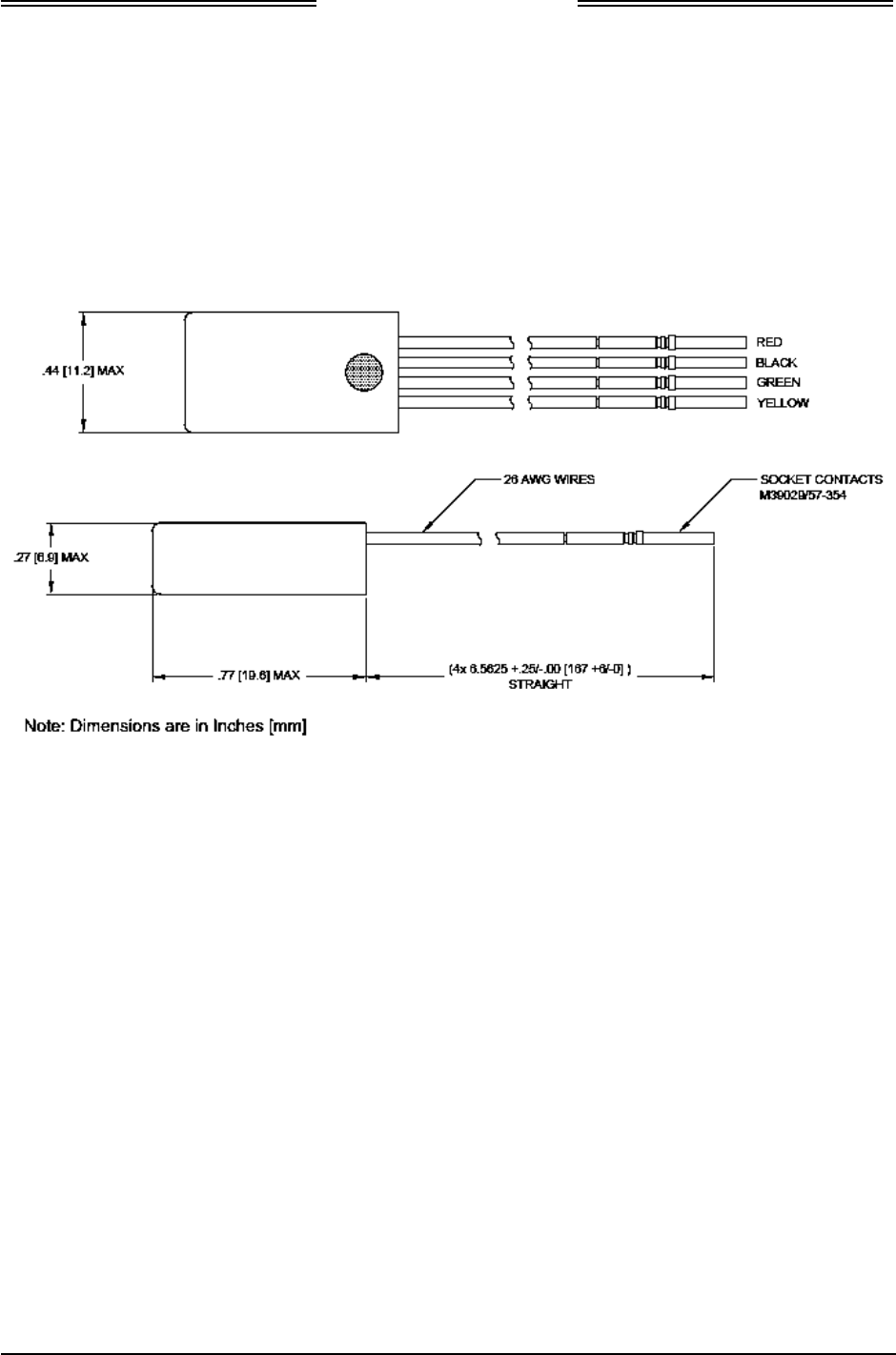
NGT-2000/2500
Installation Manual
Page 2-8 Installation 0040-17011-01
Prel-2014 Revision A
2.3.1.2 P2 Mating Connector Assembly
1. Installation Guidelines for the DCM.
a. Use the following information when locating and installing the DCM in the aircraft. Refer to
Figure 2-5 for DCM mounting location.
b. The DCM is connected to the P2 mating connector during wire installation. Refer to electrical
connections paragraph 2.3.1.1 for wiring details. Refer to Figure 2-4 for the outline dimensions
of the DCM. Refer to Figure 2-2 for interface connections to the P2 mating connector.
Figure 2-4: Outline Dimensions for the DCM
DRAFT 3-2
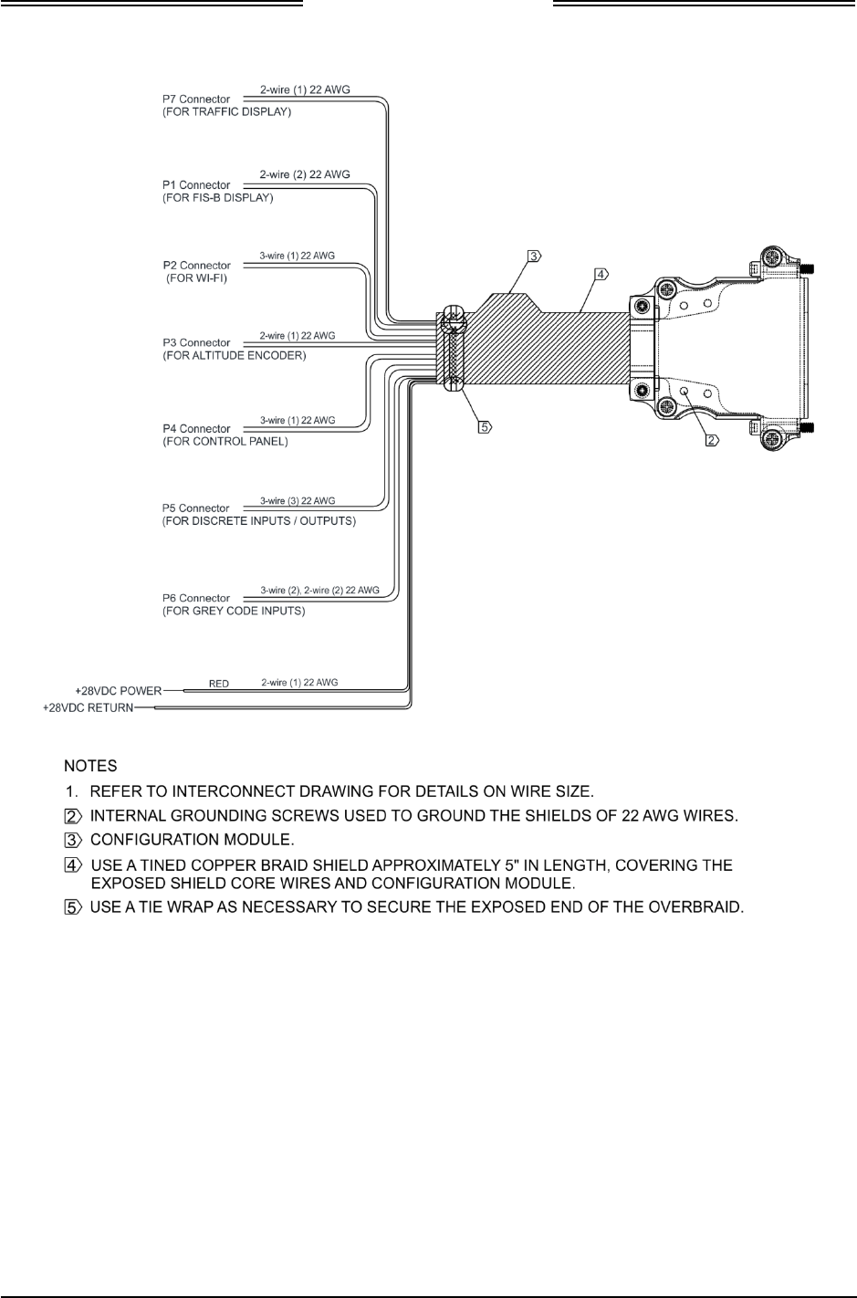
NGT-2000/2500
Installation Manual
0040-17011-01 Installation Page 2-9
Revision A Prel-2014
Figure 2-5: Mating Connector (P2) Cable Assembly
DRAFT 3-2
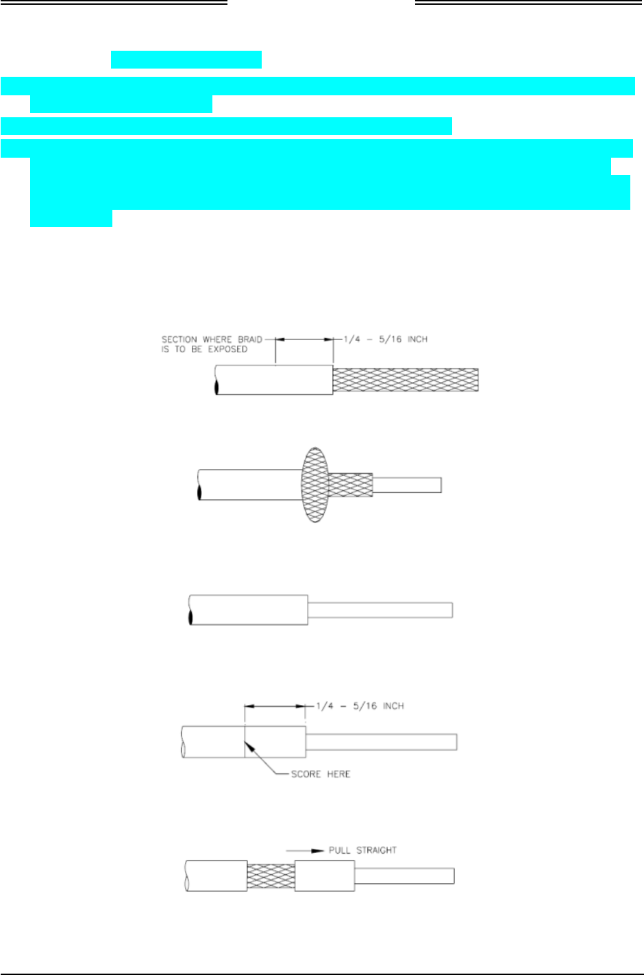
NGT-2000/2500
Installation Manual
Page 2-10 Installation 0040-17011-01
Prel-2014 Revision A
2.3.1.2.1 Shielded Cable Preparation
• Use these instructions to prepare the Shielded Tefzel Wire (MIL27500) or equivalent for connection
to the 62 pin sub D connector.
• The crimp pins of the 62 pin connector are to be crimped to the wires.
• The Outer Jacket of the cable is to be removed for all cables on which the solder sleeve to be placed
for ground contact. The installer is to ensure that the outer jacket is removed on the cable for the
length of the cable inside the 62 pin connector backshell and can be around 1 to 1.5 inches from the
crimped pin side. Refer to Table 2-1 for the procedure on how to remove the jacket and insertion of
solder sleeve.
1. The cable can be stripped according to the following procedure designed to leave the shield braid
smooth and flat. The use of finger cots is recommended to prevent transfer of oils to the shield.
a. Score and remove the jacket as shown below:
b. Bunch the braid:
c. Trim the braid as close as possible to the jacket:
d. Score the jacket ¼ to 5/16 inch from the end of the braid:
e. Remove the section of jacket carefully by pulling straight. This will flatten the braid strand ends:
f. Inspect the cable to make sure that the braid strands are lying against the primary insulation.
DRAFT 3-2
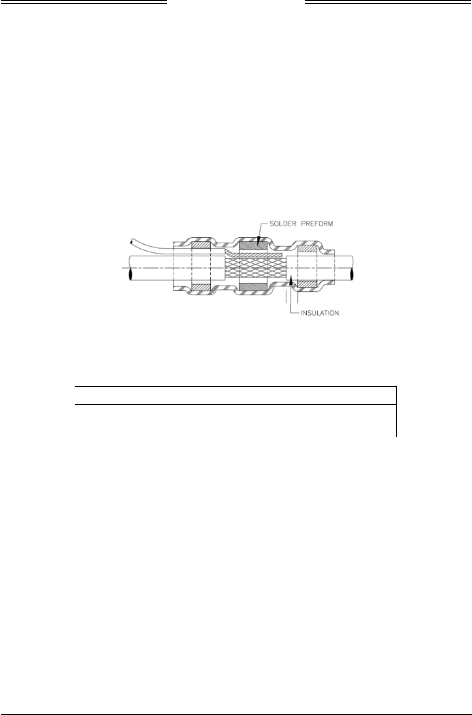
NGT-2000/2500
Installation Manual
0040-17011-01 Installation Page 2-11
Revision A Prel-2014
2. Solder Sleeve placement
NOTE
Ensure the strands of the shield braid and ground lead lay flat and smooth.
a. Position the stripped portion of ground lead (s) against the stripped portion of the shield braid.
b. Slip the selected shield terminator over the cable and ground lead assembly. Rotate the shield
terminator as it slides over the ground lead to prevent it from catching on the strands.
c. Position the terminator so that the exposed shield is centered between the solder sleeve (solder
preform) inserts and some of the cable jacket is visible between the solder sleeve inserts and the
exposed shield.
3. Apply Heating on the Solder Sleeve
a. Use Tyco Electronics approved heat source and reflector as shown below:
Heat Gun / Setting Reflector
HL1910E = 6 on dial
HL2010E = 700°F on LCD
PR-25 or PR-25D and
HL1802E-ADAPT
b. Allow hot air heaters to warm up before using.
c. Position the assembly (cable, ground lead and terminator) in the reflector so that the solder
preform is in the center of the hot air or at the focal point on the infrared heaters.
d. If the cable jacket or ground lead insulation is susceptible to heat damage for example, if the
insulation is PVC, or if the infrared heating is used with black insulation, move the assembly
toward the heat source to minimize unwanted exposure of the jacket to the heat.
e. Heat until the solder preform melts flows and wets the shield and ground lead.
f. Some terminators contain a thermal indicator to signal when the correct amount of heat has been
applied to the solder. There are two types of indicators. One is a thermo-chromic material which
signals correct heating by loss of color. Terminators with this type of indicator should be heated
until all the colored material in the joint area has turned colorless. (Slight traces of the material
may remain in the standing of the shield). The other type of thermal indicator is a ring of fusible
material around solder preform. Terminators with this Bi-Alloy indicator should be heated until
the solder preform melts and the indicator ring completely disappears in the joint area.
DRAFT 3-2

NGT-2000/2500
Installation Manual
Page 2-12 Installation 0040-17011-01
Prel-2014 Revision A
4. Assembly
a. Cut the pre-installed lead on the solder sleeve as required (keep the length as low as 1 to 1.5 inch
from the solder sleeve) and crimp the ring terminal to the wire for the ground terminations. Note
that multiple (can be 2 or 3) leads can be clubbed together for crimp to a single ring terminal.
b. Insert the ground braid (about 5 inches) to the cable harness (ensure that the DCM is also part of
this cable harness) before inserting the crimped pins of the cables to 62 pin connector and then
connect the cables as shown in the figures below:
DRAFT 3-2
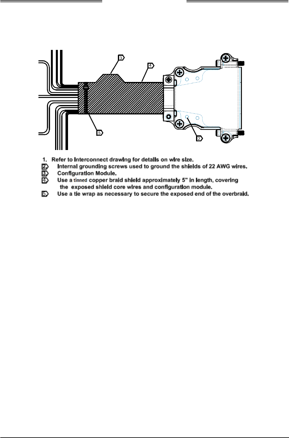
NGT-2000/2500
Installation Manual
0040-17011-01 Installation Page 2-13
Revision A Prel-2014
c. On completion of the assembly of the cables, cable tie to be used to secure the cable harness and
the cable harness with ground braid will be as shown in the figure below:
d. The installer shall ensure that the other side of the cable ground braid is also grounded for better
EMI performance of the unit.
DRAFT 3-2
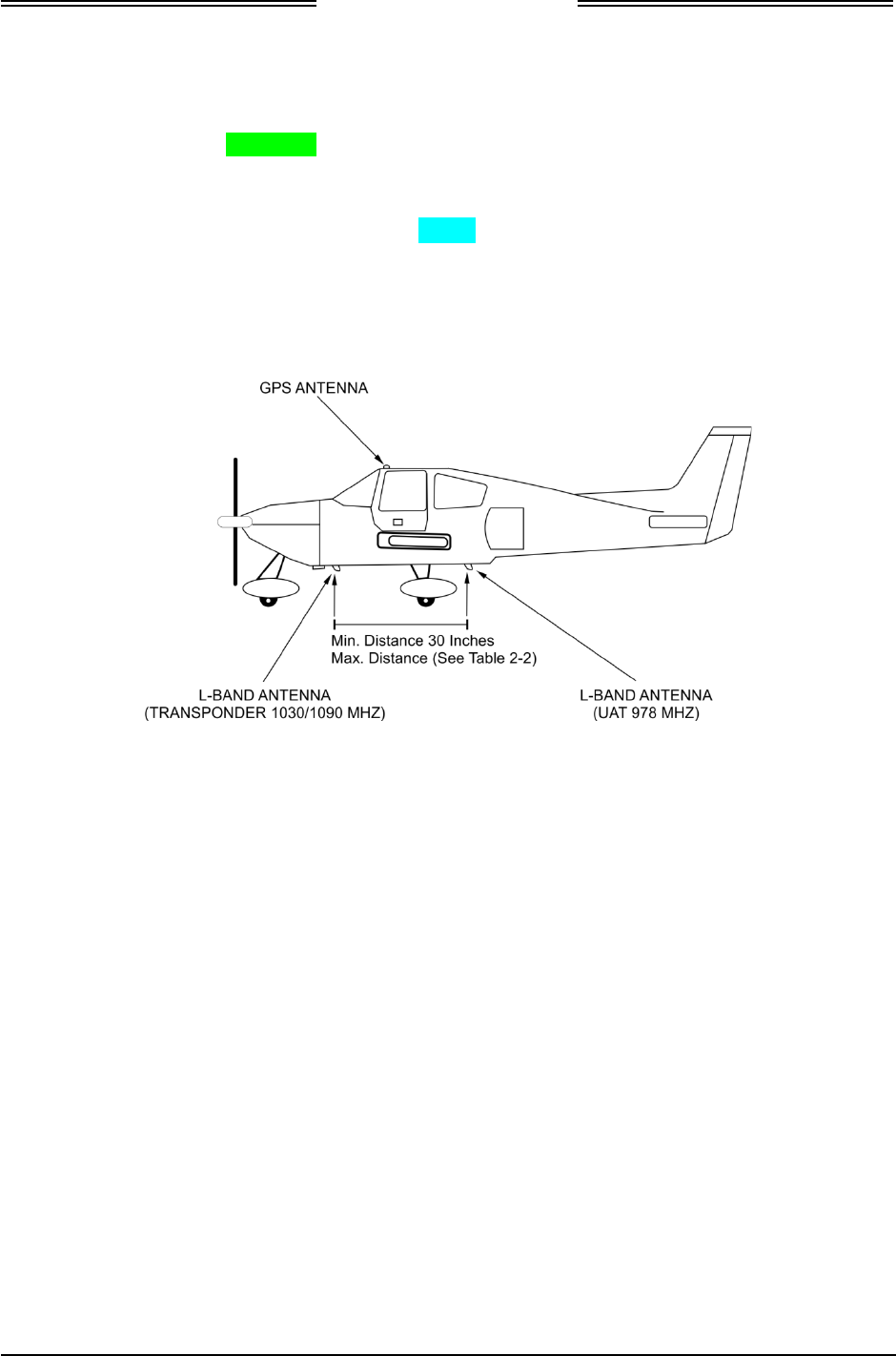
NGT-2000/2500
Installation Manual
Page 2-14 Installation 0040-17011-01
Prel-2014 Revision A
2.3.2 Antenna Installation Guidelines
This information provides general installation guidance to ensure the installed antennas meet the
requirements for the NGT-2000/2500.
• Installation approval for the GPS and L-band antennas is not provided by the instructions provided in
this manual.
• Cable requirements are located in paragraph 2.3.1.1. Cable vendors and approved antenna
manufactures are located in the General Information section.
• An example of antenna placement is shown in Figure 2-6. Refer to the aircraft manufacturer's data
and the antenna manufacturer's installation instructions to mount the antenna. The installer may use
other FAA approved data to gain a separate antenna installation approval.
Figure 2-6: Example of Antenna Mounting Locations
2.3.2.1 GPS Antenna
The GPS antenna performance is critical to the performance of the NGT-2000/2500. The antenna must
meet the minimum performance requirements for the NGT-2000/2500. Only the antennas listed in the
General Information section meet these requirements.
• The antenna performance is critical to operation of GPS in the Unit. The recommended antenna is a
DO-301 compliant antenna meeting the requirements of TSO-C190. For installations where the
aircraft has an existing antenna complying with DO-228 (TSO-C144a), the unit may be installed
utilizing this antenna, as per DO-229D Note 1, Section 2.1.1.10.
• The performance of the unit is affected by the gain, noise figure, impedance, and frequency
selectivity characteristics of the antenna. The unit should be used only with the recommended
antenna and cable. Use of other antennas or cables may not meet all the performance characteristics
specified in DO-229D.
• The cable including connectors, loss should not exceed 10dB.
DRAFT 3-2

NGT-2000/2500
Installation Manual
0040-17011-01 Installation Page 2-15
Revision A Prel-2014
2.3.2.1.1 GPS Antenna Location
The following guidance provides information to aid the installer in determining the best location is
selected for the installation of the GPS Antenna.
The installation guidelines presented here meet the intent of AC 20-138C Chapter 12, Section 12-1.
NOTE
Not all the listed installation guidelines may be possible on all aircraft.
The guidelines are listed in order of importance. The chances of optimal
signal strength are decreased if the guidelines are not followed.
1. The antenna must be located on the top of the aircraft and should be mounted in a location to
minimize the effects of airframe shadowing during typical maneuvers. Typically mounting farther
away from the tail section reduces signal blockage seen by the antenna.
2. Mount the antenna as close to level as possible with respect to the normal cruise flight attitude of the
aircraft. If the normal flight attitude is not known, substitute with the waterline, which is typically
referenced as level while performing a weight and balance check. A shim may be used to level the
antenna.
3. The antenna should be mounted no closer than 3 feet from any VHF COM antenna or any other
antenna, which may emit harmonic interference at the L1 frequency of 1575.42 MHz. An aircraft
EMI check can verify the degradation of GPS in the presence of interference signals.
• If an EMI check reveals unacceptable interference, either insert a GPS notch filter in line with
the offending VHF COM or select a different GPS Antenna location.
4. To maintain a constant gain pattern and limit degradation by the windscreen, avoid mounting the
antenna closer than 3 inches from the windscreen.
5. It is permissible to temporarily locate the GPS Antenna with a coaxial cable connected to the MSS
and check the GPS performance as described in the installation checkout section. Permanently mount
the antenna once a suitable location has been verified.
6. Once the antenna mounting position has been established, route the coaxial cable from the antenna to the
MSS. Proper selection of coaxial cable and assembly of connectors is critical to GPS signal performance.
7. For installations on rotorcraft, ensure that the rotor blades do not interfere with the GPS received
signal. This problem has been experienced in some rotorcraft and varies with rotation rate.
2.3.2.1.2 GPS Antenna Installation
Refer to the aircraft manufacturer's data and the antenna manufacturer's installation instructions to mount
the antenna. The installer may use other FAA approved data to gain a separate antenna installation
approval.
1. Electrical Bonding Requirements:
The GPS/WAAS antenna requires a minimum ground plane radius of 7.5 inches around the
perimeter of the antenna. For metal aircraft, the surrounding metal skin on which the antenna is
mounted supplies the ground plane. For non-metal aircraft, the ground plane can be composed of
heavy duty aluminum foil tape, such as 3M PIN 438 or other adhesive backed dead soft aluminum
foil minimum 0.012 inches thick. It should be noted that if the antenna is struck by lightning, the foil
by itself may not be sufficient to dissipate lightning currents. Additional protection may be needed
depending on the construction of the structure to which the antenna is mounted.
• The electrical bonding requirements stated in paragraph 2.3.1.1 must be met.
• To prepare an aluminum surface for proper bonding, refer to SAE ARP1870 Sections 5.1 and 5.5.
2. Connection to the antenna should be made in accordance with the system interconnect diagram
Figure 2-2.
DRAFT 3-2

NGT-2000/2500
Installation Manual
Page 2-16 Installation 0040-17011-01
Prel-2014 Revision A
2.3.2.2 L-Band (UAT/978) Antenna
The UAT/978 antenna must meet the minimum performance requirements for the NGT-2000/2500. Only
the antennas listed in the General Information section meet these requirements.
Antennas meeting the minimum performance specifications needed by the NGT-2000/2500 may already
be installed in the aircraft and may be available for use. Use the antenna location information below to
verify an existing antenna location is acceptable for use.
Installation approval for the UAT Antenna is not provided through this Manual.
2.3.2.2.1 L-Band (UAT/978) Antenna Location
The UAT/978 antenna installation should be installed in accordance with AC 43.12-2A Chapter 3. The
following guidance provides information to aid the installer in determining that the best location is
selected for the installation of the L-band Antenna.
• The UAT/978 antenna must be mounted vertically on the bottom of the aircraft fuselage. The
antenna shall be located to minimize obstruction to fields in the horizontal plane.
• The total attenuation including connectors shall not exceed 1.5dB. Based on this, the length of the
cable can be decided assuming RG-400 cable. RG type coaxial cable insertion loss can vary
significantly between manufacturers. Refer to the cable manufacturer's specification sheet for actual
attenuation (insertion loss) for the cable being used.
• The UAT/978 antenna should be located away from major protrusions, such as engine(s),
propeller(s), and antenna masts. It should be as far as practical from landing gear doors, access
doors, or other openings that could affect its radiation pattern.
• The UAT/978 antenna must be mounted no closer than 20 inches from any FADEC (Full Authority
Digital Engine Control).
• The UAT/978 antenna must be mounted no closer than 24 inches to any TAS/TCAS antenna.
• The UAT/978 antenna must be mounted no closer than 30 inches to any transponder antenna. Refer
to Table 2-1 for maximum distances.
• Path loss between UAT and Transponder L-Band antenna is must be 20dB to 43.7dB.
Table 2-1: Maximum UAT Antenna to Transponder Antenna Separation
UAT ANTENNA CABLE ASSEMBLY CABLE
LOSS (1)
MAXIMUM ANTENNA
SPACING (2)
0.75 dB < Cable Loss < 1.0 dB 137 inches
1.0 dB < Cable Loss < 2.0 dB 122 inches
2.0 dB < Cable Loss < 3.0 dB 109 inches
Note (1) Cable assembly cable loss includes loss of the coaxial cable with connectors.
Note (2) Measured from center of UAT/978 Antenna to the center of transponder antenna.
• When the NGT-2000/2500 is configured to communicate with the aircraft transponder using the self-
interrogation feature (CP-2500 installed), the following antenna guidelines must also be followed:
a. The installed transponder must be utilizing a bottom mounted antenna.
b. The bottom UAT/978 Antenna must be mounted no further from the transponder antenna than
specified in Table 2-1.
DRAFT 3-2

NGT-2000/2500
Installation Manual
0040-17011-01 Installation Page 2-17
Revision A Prel-2014
2.3.2.3 L-Band (UAT/978) Antenna Installation
Refer to the aircraft manufacturer's data and the antenna manufacturer's installation instructions to mount
the antenna(s). The installer may use other FAA approved data to gain a separate antenna installation
approval.
• Electrical Bonding Requirements:
Each L-Band antenna requires a minimum ground plane radius of 12 inches around the perimeter of
the antenna. For metal aircraft, the surrounding metal skin on which the antenna is mounted supplies
the ground plane. For non-metal aircraft, the ground plane can be composed of heavy duty aluminum
foil tape, such as 3M PIN 438 or other adhesive backed dead soft aluminum foil minimum 0.012
inches thick. It should be noted that if the antenna is struck by lightning, the foil by itself may not be
sufficient to dissipate lightning currents. Additional protection may be needed depending on the
construction of the structure to which the antenna is mounted.
The electrical bonding requirements stated in paragraph 2.3.1.1 must be met.
• Connection to the antenna should be made in accordance with the system interconnect diagram
Figure 2-2.
• Acceptable coaxial cable attenuation at 978 MHz is between 0.75 dB and 1.5 dB, including
connectors.
• Reference General Information Section – Antenna Cables for UAT Antenna cable loss and minimum
antenna spacing requirements.
• Refer to General Information section - lists some suitable cable types. Any 50Ω, double-shielded
coaxial cable assembly that meets airworthiness requirements and the acceptable attenuation
requirements (including connectors) may be used. When computing cable loss, a typical loss of 0.2
dB can be used for each connection. Refer to paragraph 2.3.7 Antenna electrical bonding
requirements.
2.3.3 NGT-2000/2500 Installation
Perform the following to the extent necessary to install the NGT-2000/2500:
1. Place the unit in the location selected in paragraph 2.3.1.
2. Use four customer supplied fasteners to mount the unit to the aircraft.
3. Connect P2 mating connector to connector J2 of the unit.
4. Connect GPS and L-Band antenna to unit at appropriately marked TNC connections.
2.3.4 Remove and Replacement Procedures
If the NGT-2000/2500 or one of its system components requires removal after initial installation, replace
it using the instructions given in the maintenance section of this manual.
DRAFT 3-2

NGT-2000/2500
Installation Manual
Page 2-18 Installation 0040-17011-01
Prel-2014 Revision A
This page intentionally left blank.
DRAFT 3-2

NGT-2000/2500
Installation Manual
0040-17011-01 Installation Checkout Page 3-1
Revision A Prel-2014
Section 3
Installation Checkout
3.1 INTRODUCTION
This section contains instructions to check out the installation of the NGT-2000/2500 (MSS) and
configuration module. Refer to the fault isolation information provided in the maintenance manual for help
in correcting installation issues found during checkout. Refer to the General Information section -
Equipment Required Not Supplied for details on equipment used in this section.
The installation of the NGT-2000/2500 requires an approved control panel/display. Note that approved
control panel/display may not operate exactly as stated in this checkout. Refer to the operating
instructions for the controller/display for details.
NOTE
These procedures assume that the mounting, wiring, power, and antenna
requirements have been checked out according to the instructions given
in the installation section.
CAUTION
Operating the unit with the GPS antenna connected and the UAT antenna
NOT connected may damage the unit.
DRAFT 3-2
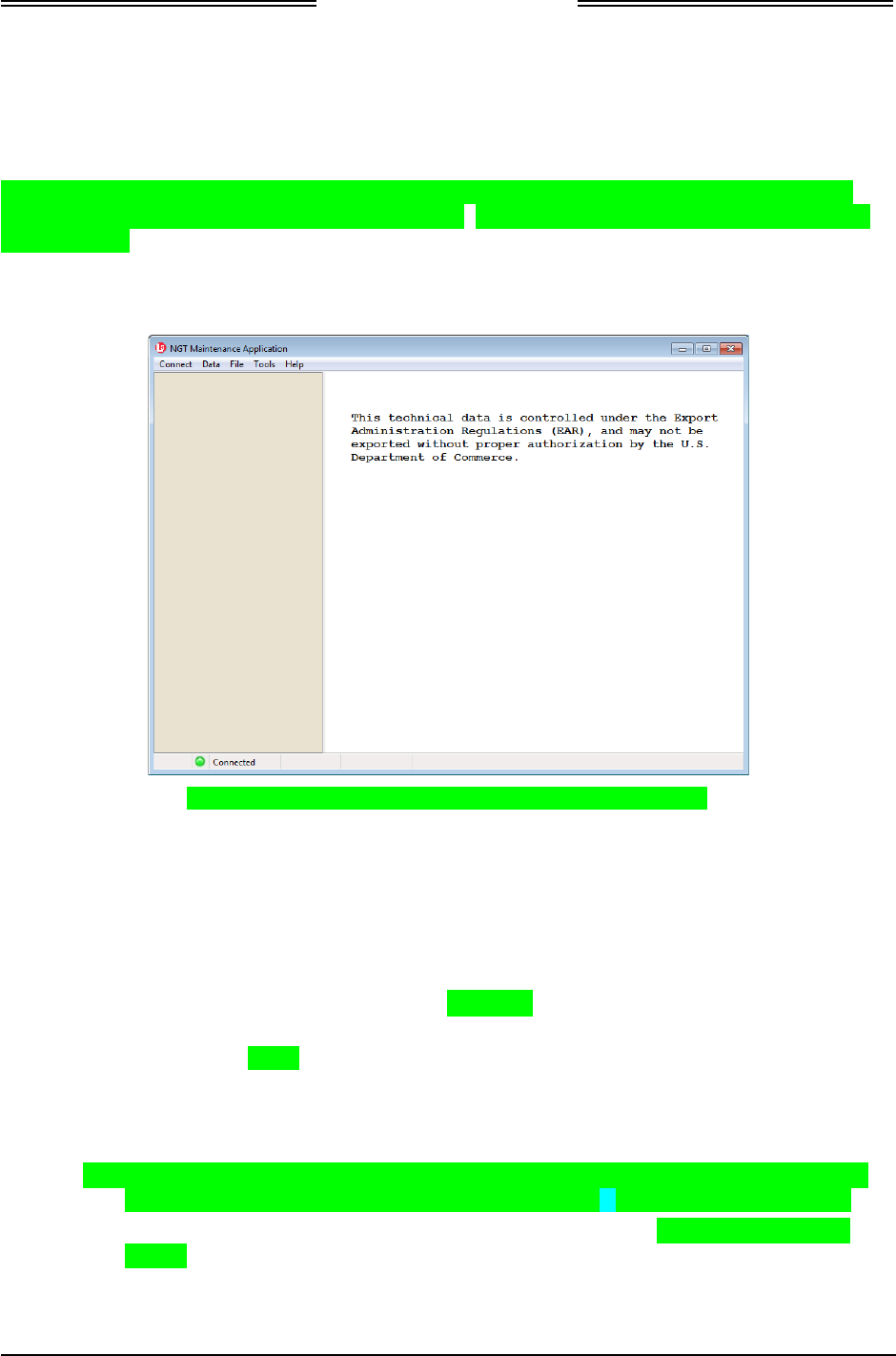
NGT-2000/2500
Installation Manual
Page 3-2 Installation Checkout 0040-17011-01
Prel-2014 Revision A
3.2 MAINTENANCE PC
The procedures for installation checkout require the use of a Maintenance PC (MPC), NGT Maintenance
Appliance Tool (NGT MAT) and a USB cable. The MPC may only be connected and used while the
aircraft is on ground. An example of the main page of the NGT MAT is shown in Figure 3-1.
The revision of the NGT MAT must be compatible with the unit’s software release. Refer to software
revisions in the General information section for details. The revision of the MPC MAT can be found in
the Help menu.
Persons performing the checkout should monitor the NGT MAT status bar (located at the bottom of the
screen) for messages and modes of operation.
Figure 3-1: NGT Maintenance Appliance Tool – Main Page
• Do the following to connect and establish communication between the MPC and the MSS via the
USB connection.
a. Apply power to the MSS and MPC.
b. The NGT MAT is active on the MPC.
c. Connect USB cable between MPC and the MSS.
d. From the NGT MAT menu select ConnectZAppliance Z USB.
e. Communication is established when the NGT MAT left view panel changes from grey to tan and
the message ‘Connected’ is shown in the lower status bar.
• If “Not Connected” is shown, then check the USB cable for proper connection.
• If a “Response timeout for write request” message is seen on the status bar, then the unit is
not responding to requests. Cycle power to the MSS.
• The NGT MAT transitions into different modes depending on what is currently selected.
The current mode can be determined by viewing the lower left corner of the status bar.
• Within the first 2 minutes of cycling power to the MSS the Maint Mode can always be
entered. If after 2 minutes of cycling power and the GPS signal has not yet been acquired
then the Maint Mode cannot be entered. The unit will need to be cycled again before Maint
Mode can be entered by the NGT MAT.
DRAFT 3-2
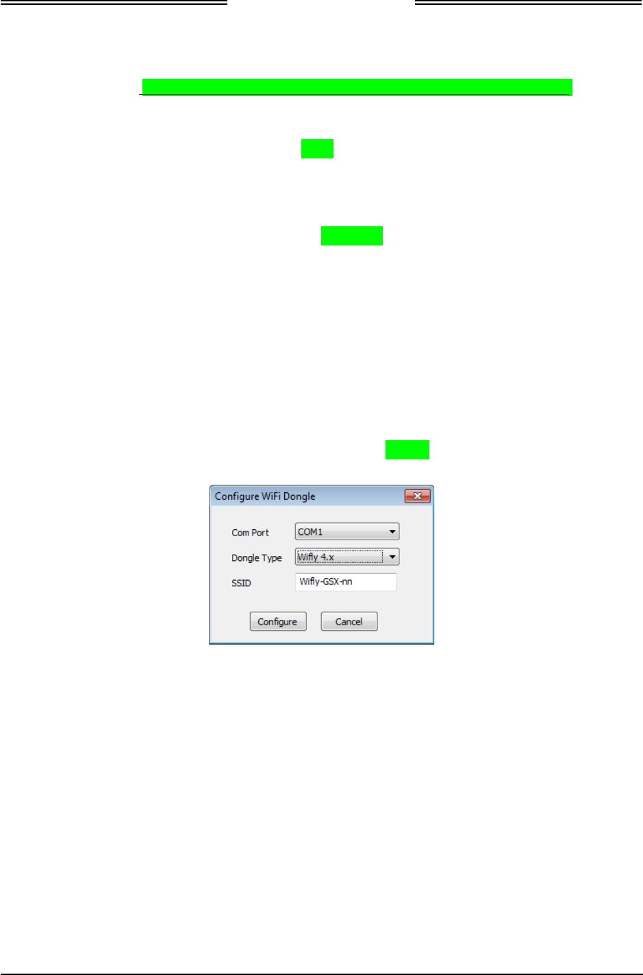
NGT-2000/2500
Installation Manual
0040-17011-01 Installation Checkout Page 3-3
Revision A Prel-2014
• Do the following to connect and establish communication between the MPC and the MSS via the
WiFi connection. Note –This feature will be added in a future revision of the NGT MAT.
a. After communication has been established using the instructions in step 1, WiFi communication
can be established with the MSS for installation using the WiFi option. Refer to paragraph 3.3.
b. From the NGT MAT menu select ServiceZ Maintenance through WiFi.
c. Press the Request button.
d. Cycle power to the unit.
e. Remove USB cable.
f. From the NGT MAT menu select ConnectZAppliance Z WiFi.
g. Connection should be established. If not, than restart the process begun in step 2.a.
3.3 CONFIGURE WIFI ACCESSORY
This procedure requires a Maintenance PC (MPC), NGT Maintenance Appliance Tool (NGT MAT), and
a standard Null Modem cable (DB9 F/F).
These procedures assume the following:
• The NGT MAT is active on the MPC.
1. Connect WiFi Accessory to the MPC Com Port 1 using a standard Null Modem cable.
2. From the NGT MAT menu select ToolsZConfigure WiFi Dongle. See Figure 3-2.
Figure 3-2: NGT MAT – WiFi Accessory
3. Select the accessory Type.
4. Enter the SSID (4.x only) if the entry field is not grayed out and accessible. Otherwise the SSID is
already loaded.
5. Click “Configure” to begin. A message is shown to indicate configuration complete or if
configuration could not be completed.
DRAFT 3-2
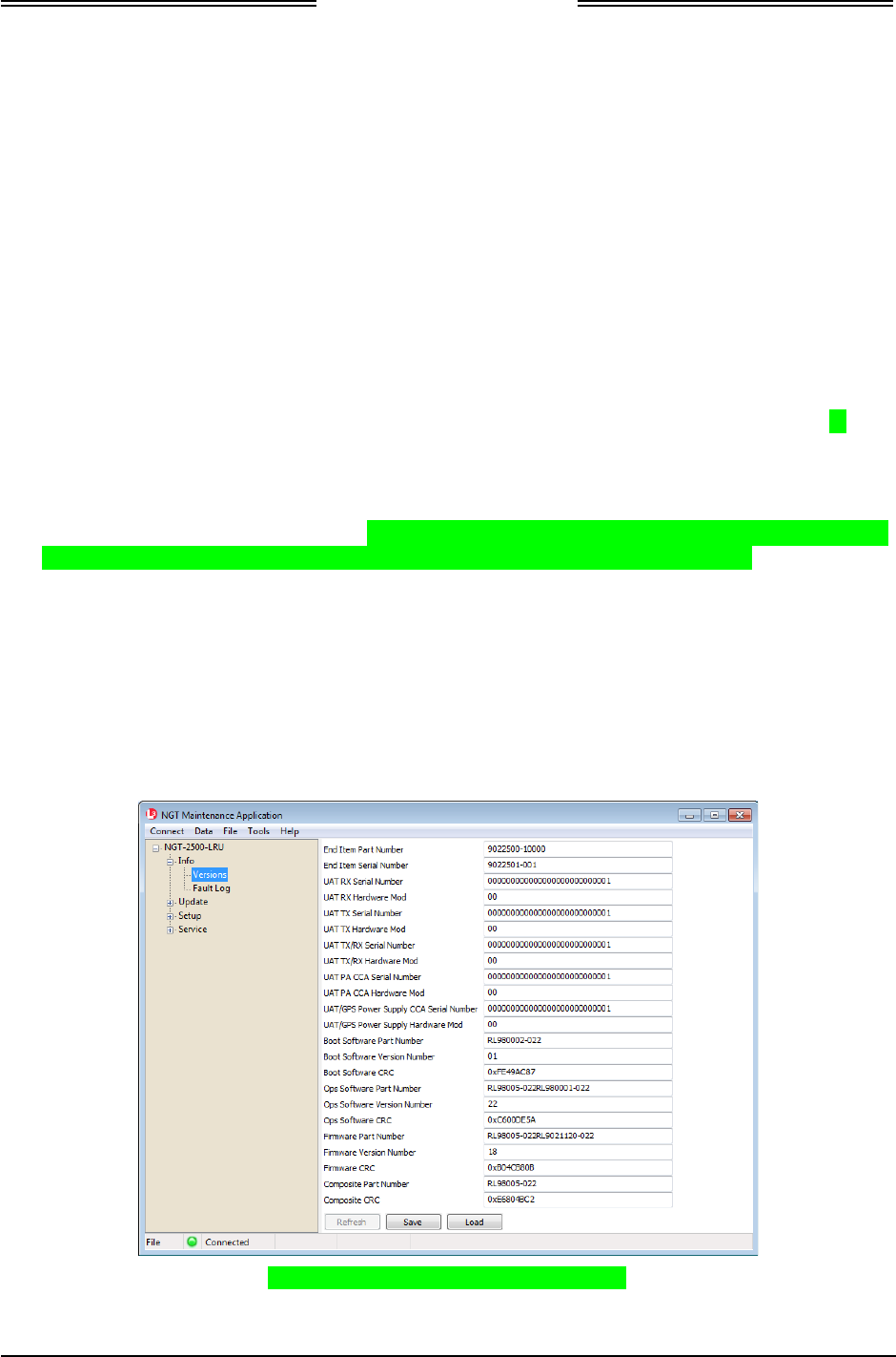
NGT-2000/2500
Installation Manual
Page 3-4 Installation Checkout 0040-17011-01
Prel-2014 Revision A
6. If the configuration could not be completed, then check the following:
• Cable connection
• Com port connection
• Accessory type
• Correct SSID
• Check batteries for the WiFi Accessory
7. After the configuration is complete remove the serial cable and connect the accessory to the aircraft
wiring harness connecting to the NGT-2000/2500.
3.4 VERIFY SOFTWARE VERSION
The Maintenance PC (MPC) and NGT Maintenance Appliance Tool (NGT MAT) are used to interface
with the NGT-2000/2500 to load software / firmware, view factory / version data, and retrieve fault logs.
These procedures assume the following:
• Power is being supplied to the aircraft and NGT-2000/2500.
• The MPC is interfaced to the unit using the USB interface.
• The NGT MAT is active on the MPC. (Note – If Maint Mode is not accessible, then it is likely that 2
minutes have passed since power was cycled with no GPS lock. Cycle power again.)
1. From the NGT MAT select InfoZ Versions. See Figure 3-3.
2. Verify that the composite software, boot loader software, and NGT MAT software are correct for
this installation. Details on software versions are available in the General Information section under
paragraph heading ‘Software Versions’.
• If a software version is found to be incorrect, update using the procedures located in the
maintenance section of this manual.
Figure 3-3: NGT MAT – Check Versions
DRAFT 3-2
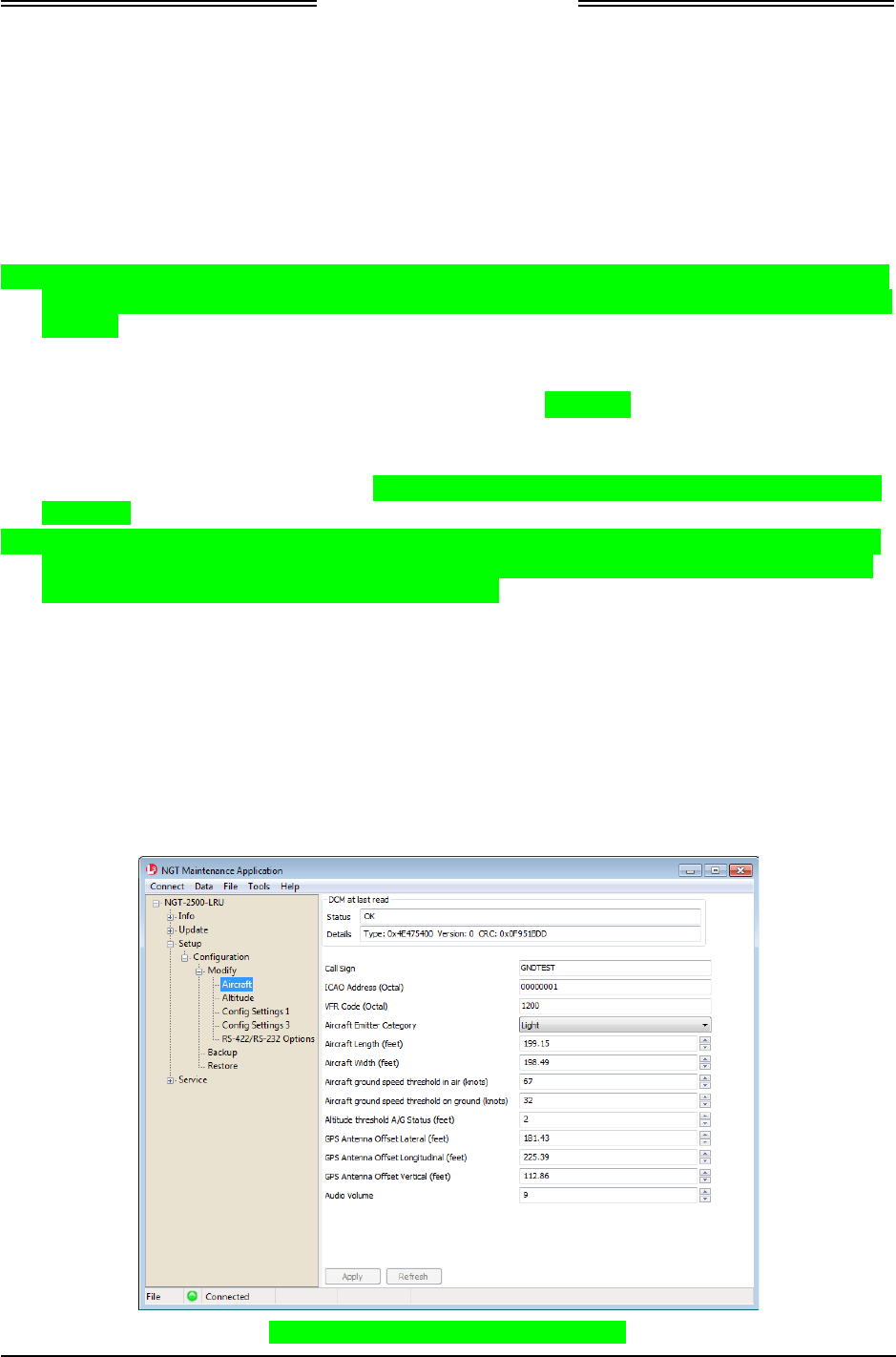
NGT-2000/2500
Installation Manual
0040-17011-01 Installation Checkout Page 3-5
Revision A Prel-2014
3.5 SELECT CONFIGURATION OPTIONS
This procedure is used to configure the NGT-2000/2500 and must be completed prior to performing the
Installation Checkout for first time installations. The Log Sheet provided in Appendix C should be filled
out prior to this procedure and maintained with the aircrafts permanent records.
• If a configuration file has already been created using the NGT MAT Backup function, then it may be
used to load the data options. The configuration restore procedure is located in the maintenance
section.
• A product key is required to enable the NGT-2500 system. The product key is typically shipped with
the unit. If the product key is not included, contact L-3 Avionics Systems Customer Service to obtain
the code.
• If the NGT MAT is not connected or is disconnected the left side panel color changes to a light grey
and the “Not Connected” message is displayed at the bottom of the tool screen. Re-connect by doing
the following - from the NGT MAT panel select ConnectZApplianceZUSB. This is required each
time the unit power is cycled.
• Place the curser over option titles to view tool tips (not always available).
• The top of the each configuration page has a DCM read monitor that checks the interface of the unit
and DCM.
• A “Warning” message is shown when the user first attempts an operation that requires confirmation
from the user stating “Changes should be done by trained service personnel”. The user will need to
press the confirm button to acknowledge this warning.
These procedures assume the following:
• Power is being supplied to the MSS and system components (i.e. antenna, display, and controllers).
• The NGT MAT is active on the MPC.
• The MPC is connected to the unit via the USB interface
• The MPC and unit are communicating.
3.5.1 Aircraft Options
1. From the NGT MAT select SetupZ Configuration Z Modify Z Aircraft. See Figure 3-4.
Figure 3-4: NGT MAT – Aircraft Options
DRAFT 3-2

NGT-2000/2500
Installation Manual
Page 3-6 Installation Checkout 0040-17011-01
Prel-2014 Revision A
2. Enter the information specific to the installation for the intended certification. Review the
information below before entering the data.
• Call Sign. Or Flight ID (Aircraft Registration Number i.e. N12345) is assigned to an aircraft for
voice communications purposes.
• ICAO Address (Octal). (Mode S Identifier). This 24-Bit unique address is assigned to an
aircraft during the registration process. The code can be obtained from either the aircraft
registration certificate or the N number inquiry pageZ http://registry.faa.gov/aircraftinquiry/.
The ICAO address must be entered before upgrading the unit to a NGT-2500. If the ICAO
address is changed after the model upgrade code is entered, than the unit will be downgraded to
a NGT-2000 and the upgrade code will need to be entered again.
• VFR Code (Octal). Permits the use of different VFR codes for different regions / altitudes in
the world. (i.e. 1200 for USA).
• Aircraft Emitter Category. This information provides an indication of the aircrafts size and
performance capabilities. Emitter categories are defined in TSO-C166b and TSO-C154c or
Table 1 in AC20-165A.
• Aircraft Length (feet). This parameter provides ATC and other aircraft with quick reference to
the aircraft’s dimensions while on the surface.
• Aircraft Width (feet). This parameter provides ATC and other aircraft with quick reference to
the aircraft’s dimensions while on the surface.
• Aircraft ground speed threshold in air (knots). This will set the minimum ground speed of
the aircraft, used in determination of air-ground status while the aircraft is in-air.
• Aircraft ground speed threshold on ground (knots). This will set the max ground speed of
the aircraft, used in determination of air-ground status while the aircraft is on-Ground.
• Altitude threshold A/G Status (feet). This provides the minimum elevation above the ground
reference for the A/G status to be considered as In-Air.
• GPS Antenna Offset Lateral (feet). These parameters are derived from the position source and
provide a geometric based position. Reference all geometric position elements broadcast from
the ADS-B unit to the World Geodetic System 1984 (WGS-84) ellipsoid.
• GPS Antenna Offset Longitudinal (feet). These parameters are derived from the position
source and provide a geometric based position. Reference all geometric position elements
broadcast from the ADS-B unit to the World Geodetic System 1984 (WGS-84) ellipsoid.
• GPS Antenna Vertical Offsets (feet). This is to provide the position offset of the GPS antenna
from the ground.
• Audio Volume. Use for Installation adjustment of audio output volume (Future).
3. Click on “Apply” after all information is entered. This information is saved to the DCM.
DRAFT 3-2
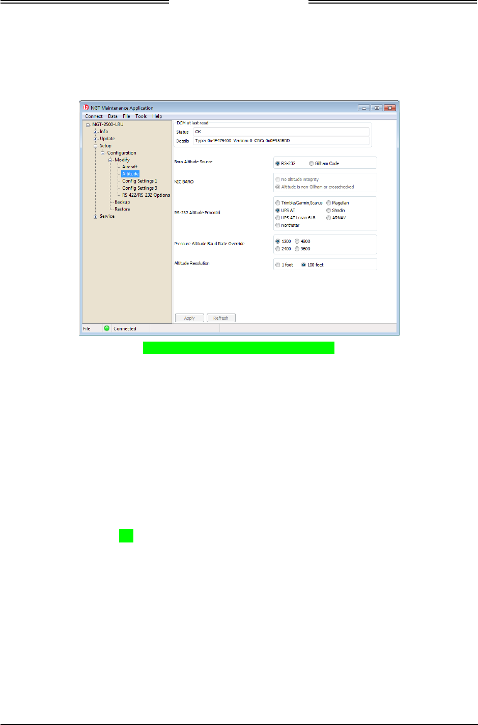
NGT-2000/2500
Installation Manual
0040-17011-01 Installation Checkout Page 3-7
Revision A Prel-2014
3.5.2 Altitude Options
1. From the NGT MAT select SetupZ ConfigurationZ ModifyZ Altitude. See Figure 3-5.
Figure 3-5: NGT MAT – Altitude Options
2. Enter the information specific to the installation for the intended certification. Review the
information below before entering the data.
• Baro Altitude Source. Indicates if the Baro Altitude source is RS-232 or 11-bit discrete
Gillham code.
• NIC BARO. Sets the NIC (navigation integrity category) baro to be used in ADS-B Messages.
Selecting non-Gillham altitude source sets the NIC Baro to 1. Selecting no altitude integrity sets
the NIC Baro to 0.
• RS-232 Altitude Protocol. Sets the protocol that the transmitted serial altitude is read from the
configuration module at start-up.
• Pressure Altitude Baud Rate Override. Used to override the automatic selection of baud rate
when one of the 7 protocols is selected.
• Altitude Resolution. Setting based on the installed altitude source. 1 foot for RS-232. 100 feet
for Gillham Code.
3. Click on “Apply” after all information is entered. This information is saved to the DCM.
DRAFT 3-2
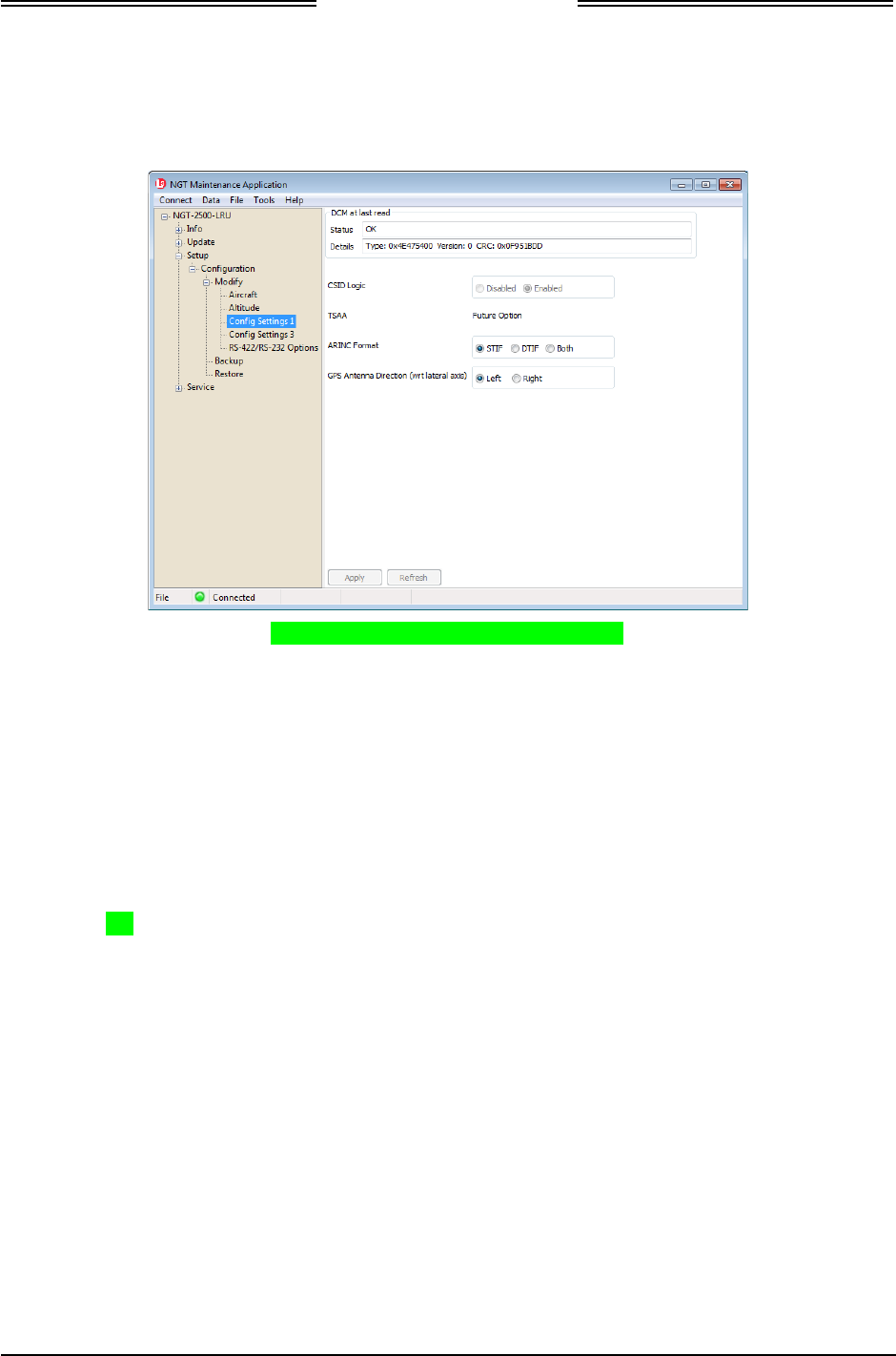
NGT-2000/2500
Installation Manual
Page 3-8 Installation Checkout 0040-17011-01
Prel-2014 Revision A
3.5.3 Config Settings 1
1. From the NGT MAT select SetupZ ConfigurationZ ModifyZ Config Settings 1. See Figure 3-6.
Figure 3-6: NGT MAT-Config Settings 1
2. Enter the information specific to the installation for the intended certification. Review the
information below before entering the data.
• CSID Logic. Call-Sign Identification (CSID) logic configuration setting shall be enabled or
disabled in the DCM. When the CSID logic is enabled, the UAT transmits call sign and Flight
Plan ID alternately in the ADS-B messages. When CSID is set to disabled, only call sign is
transmitted.
• TSAA. (Future Option).
• ARINC Format. Used in creation of ARINC messages to be transmitted to Traffic Display.
(NGT-2500 only)
• GPS Antenna Direction (with respect to lateral axis). Sets the direction of the GPS axis
along the lateral axis – left or right.
3. Click on “Apply” after all information is entered. This information is saved to the DCM.
DRAFT 3-2
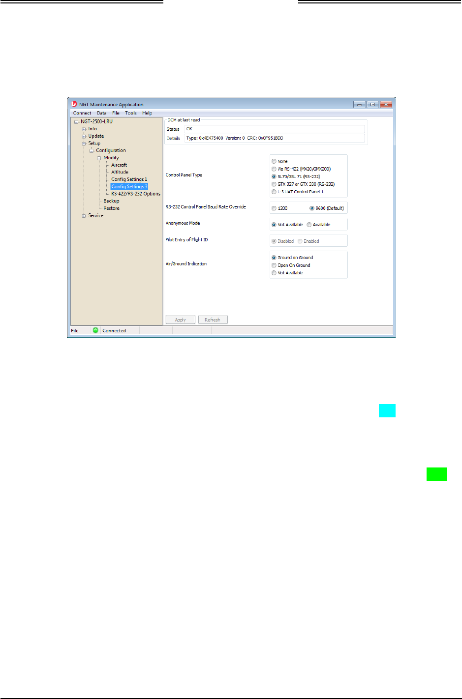
NGT-2000/2500
Installation Manual
0040-17011-01 Installation Checkout Page 3-9
Revision A Prel-2014
3.5.4 Config Settings 3
1. From the NGT MAT select SetupZ ConfigurationZ ModifyZ Config Settings 3. See Figure 3-7.
Figure 3-7: NGT MAT - Config Settings 3
2. Enter the information specific to the installation for the intended certification. Review the
information below before entering the data.
• Control Panel Type. Used to indicate if the control panel used is: Via Serial RS-422
(MX20/GMX200), SL70/GSL 71 (RS-232), GTX 327 or GTX 330 (RS-232), L-3 UAT Control
Panel 1 (i.e. CP-2500), Other Type.
• RS-232 Control Panel Baud Rate Override. (1200, 9600)
• Anonymous Mode. Indicates if the aircraft has the ability to use Anonymous Mode or not. This
function is used by the CP-2500 Control Panel.
• Pilot Entry of Flight ID. (Disable , Enable)
• Air/Ground Indication. Use to indicate the interpretation of the A/G (WOW/Squat Switch)
discrete.
3. Click on “Apply” after all information is entered. This information is saved to the DCM.
DRAFT 3-2
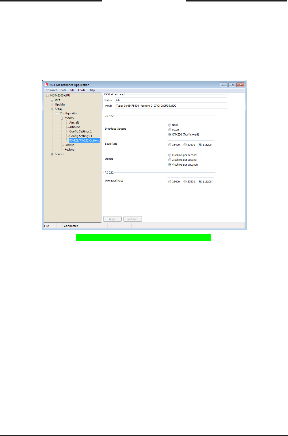
NGT-2000/2500
Installation Manual
Page 3-10 Installation Checkout 0040-17011-01
Prel-2014 Revision A
3.5.5 RS-422/RS-232 Options
1. These configuration settings are for the NGT-2500 only. Installations for the NGT-2000 can ignore
this procedure.
2. From the NGT MAT select SetupZ ConfigurationZ ModifyZ RS-422/RS-232 Options. See Figure
3-8.
Figure 3-8: NGT MAT - RS-422/RS-232 Options
3. Enter the information specific to the installation for the intended certification. Review the
information below before entering the data.
• Interface Options. Use to select the RS-422 output format.
• Baud Rate. Sets the baud rate of the RS-422 output.
• Uplinks. Sets the max number of ground uplink messages that can be transmitted per second
over RS-422.
• WiFi Baud Rate. Sets the baud rate to be used for the Wi-Fi RS-232 communication.
4. Click on “Apply” after all information is entered. This information is saved to the DCM.
DRAFT 3-2
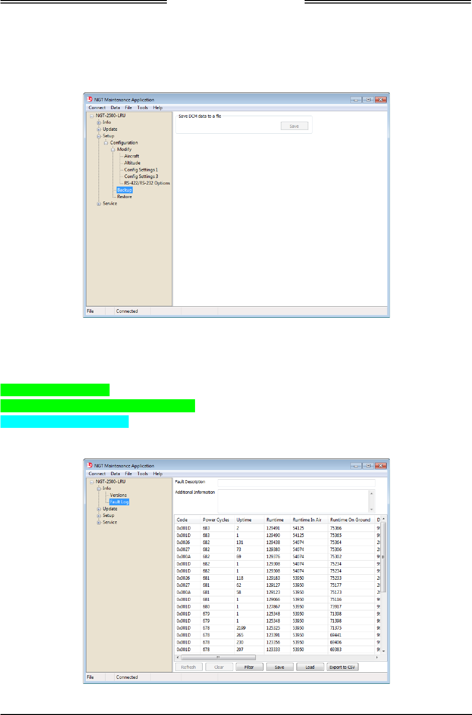
NGT-2000/2500
Installation Manual
0040-17011-01 Installation Checkout Page 3-11
Revision A Prel-2014
3.5.6 Backup
1. From the NGT MAT select SetupZ ConfigurationZ Backup.
2. Click “Save” to copy the configuration information to a file on the MPC. See Figure 3-9.
Figure 3-9: NGT MAT - Configuration Backup
3.5.7 Clear Fault Log
1. Clear the fault log from the NGT MAT by selecting Info Z Fault Log See Figure 3-10.
2. Select Clear button.
3. Answer “Yes” to confirmation dialogs.
4. Cycle power to the unit.
5. The calibration and configuration setup is complete.
Figure 3-10: NGT MAT –Fault Log
DRAFT 3-2
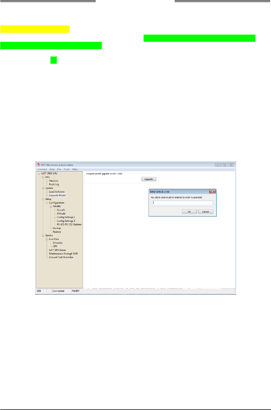
NGT-2000/2500
Installation Manual
Page 3-12 Installation Checkout 0040-17011-01
Prel-2014 Revision A
3.6 UPGRADE MODEL
Use this procedure to upgrade the MSS to a NGT-2500. The selection is only available when “NGT-
2000-LRU” is at the top of the item list. It is recommended that the ICAO Address be set up in the
configuration options before the upgrade procedure is performed. The upgrade code is set to only one
ICAO Address and no other address will work. (Note - If needed, remove the NGT-2500 upgrade by
entering a new ICAO Address and press apply.)
1. From the NGT MAT select UpdateZ Upgrade Model.
2. Press the Upgrade button. See Figure 3-9.
3. Enter the unlock code and press OK.
4. The message “Model number change succeeded. Unit will reset.” is shown.
5. Confirm the change after reconnecting and observe that the model listed on the NGT MAT is
identified as NGT-2500.
6. The Configuration option “RS-422/RS-232 Options” will now work in the unit.
Figure 3-11: NGT MAT – Upgrade Model
DRAFT 3-2

NGT-2000/2500
Installation Manual
0040-17011-01 Installation Checkout Page 3-13
Revision A Prel-2014
3.7 INSTALLATION CHECKOUT
This procedure validates the installation and configuration setup of the NGT-2000/2500 MSS and
secondary equipment. Installers are advised to read through the entire procedure before performing the
checkout. Take the following into consideration prior to installation.
• Perform the installation checkout procedure with aircraft on ground.
• Perform only those checks that are applicable to the installation.
• To conserve aircraft battery power, it is recommended that the aircraft be connected to an external
aircraft power source during installation and checkout.
• An IFR-6000 (or equivalent) Ramp Test Set is required. These checks assume familiarity with the set
up and operation of the ramp test set.
• All test equipment shall be calibrated in accordance with the manufacturer's recommendations.
• The approved display/control panel/PED may not operate exactly as stated in this checkout. Refer to
the operating instructions for the controller/display/PED for details.
• The CP-2500 Control Panel is specifically designed to interface with the MSS and may be used
during the checkout to verify the operation of the MSS.
• Depending on the installation - when power is applied to the unit the following indication is
observed while the GPS initializing (acquiring a signal).
o The CP-2500 shows a GPS INIT message.
o The ADS-B Fail indicator lamp flashes ON/OFF.
o Approved equipment may have its own kind of message or indication.
• It is normal for the ADS-B Out Of Coverage indictor/lamp to be ON during checkout if there is not a
ADS-B ground station or signal within range.
• Some tests require the unit be set to Ground Test Mode. This is accomplished from the NGT MAT
by selecting ServiceZ Live DataZ Ground Test Overrides and setting the ground speed to greater
than 7kts (which sets the unit to Operate mode) and setting the track to a desired heading (which
points the traffic on the traffic screen in the correct orientation). Press the Enable button to enter
ground test mode and disable to return to normal operation mode. See Figure 3-12.
The ground test mode also sets the unit to “In-Air” status allowing Mode C (altitude) output and
additional ADS-B output messages (sent at a higher rate). This allows the IFR-6000 to test the
encoding altimeter input (mode C).
• These procedures assume the following:
o Power is being supplied to the MSS and system components (i.e. antenna, display, and controllers).
o The NGT MAT is active on the MPC.
o The MPC is connected to the unit via the USB interface
o The MPC and unit are communicating.
DRAFT 3-2
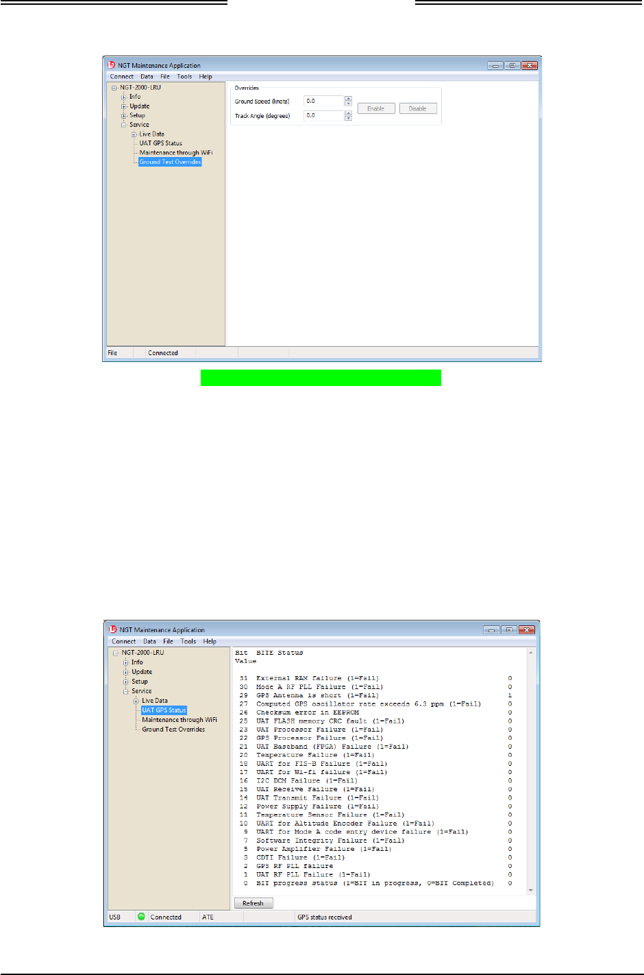
NGT-2000/2500
Installation Manual
Page 3-14 Installation Checkout 0040-17011-01
Prel-2014 Revision A
Figure 3-12: NGT MAT – Ground Test
3.7.1 Functional Check
The power ON self-test (PBIT) and continuous self-test (CBIT) checks the operation and the major
hardware components in the unit. Verify this by viewing the Status information provided by the NGT
MAT as follows:
1. From the NGT MAT select ServiceZ Live DataZ UAT GPS Status. See Figure 3-13.
2. Review the BITE Status and verify that no failures, indicated by a ‘1’ in the right column, are
present.
3. If a failure is observed the problem must be resolved before continuing with the checkout. Use the
MPC fault log as well as the troubleshooting help in the maintenance section.
Figure 3-13: NGT MAT – UAT GPS Status
DRAFT 3-2

NGT-2000/2500
Installation Manual
0040-17011-01 Installation Checkout Page 3-15
Revision A Prel-2014
3.7.1.1 Indicator Lamp Check
Verify the following indicator lamps functioning properly (if installed) during the checkout. These lamps
are required if the control panel installed on the aircraft does not provide the indications stated below.
Note – the CP-2500 is capable of displaying messages of both these indications.
1. ADS-B Failure – This lamp does the following depending on the situation:
• Flashes at a slow rate while the GPS is initializing. Check by cycling power to the unit.
Flashing will last only 2 minutes before the lamp stays ON.
• Flashes at a fast rate if a code mismatch is detected. Check by entering the different Mode A
code from the one being transmitted by the transponder.
• The lamp is ON when the ADS-B has failed or if the MSS Transmit ON/OFF switch is set OFF.
2. No ADS-B Coverage – This lamp is ON if no ground station signal is detected. The lamp is OFF
when a signal is detected either by a ground station or when the IFR-6000 is used for ADS-B checks.
3.7.1.2 Discrete Switch Checks
Verify the following external switches are functioning properly (if installed) during the checkout. The
Ident and MSS Transmit On/Off switches are required if the control panel installed on the aircraft does
not provide the functions stated below. Note – the CP-2500 is capable of performing these functions.
1. Verify that the IDENT Input switch causes an annunciation on the display/PED.
2. Set the MSS Transmit ON/OFF switch ON and causes the ADS-B Fail indicator/Lamp ON. Set the
switch to OFF to set the ADS-B Fail indicator/Lamp OFF.
3. The On-Ground switch function is verified by….
3.7.1.3 Control Panel Check
The NGT-2000 and NGT-2500 require an approved control panel (RS-232) to operate. The instructions
provided in this manual for the control panel are generic. Refer to the manufacturers control panel manual
for operation and checkout procedures.
3.7.1.4 Suppression Pulse Check
Use an oscilloscope to verify that the RF Suppression pulse (Discrete #2 out) is 100 µs ±5µs, +28 V dc
when the unit is transmitting.
3.7.1.5 Display Check
The NGT-2500 may be interfaced to an approved traffic display (ARINC 429) and weather display (RS-
422). The instructions provided in this manual are generic. Refer to the manufacturers display manual for
operation and checkout procedures.
• A functional check with the MSS is accomplished during the check of the ADS-B In, TIS-B, FIS-B
and any other checks requiring the use of a Display.
DRAFT 3-2
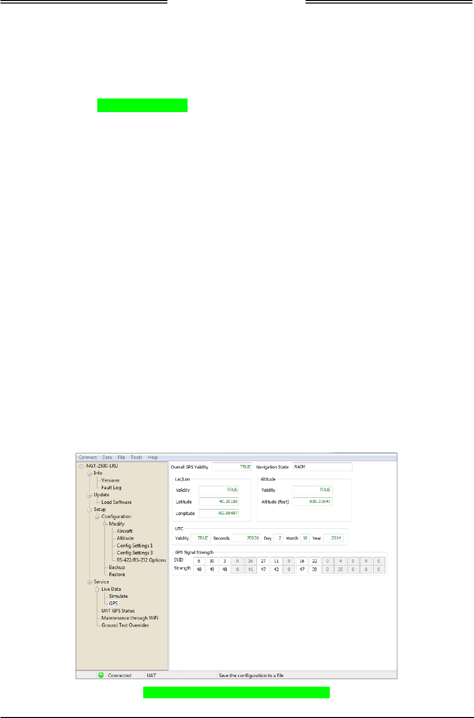
NGT-2000/2500
Installation Manual
Page 3-16 Installation Checkout 0040-17011-01
Prel-2014 Revision A
3.7.1.6 PED Check
The PED (Personal Electronic Device) requires that a WiFi accessory be connected to the wiring harness
and the WiFi configuration option be set up. This option may be used by both the NGT-2000 and NGT-
2500.
• The PED requires a compatible APP.
• The PED and MSS WiFi interface must be configured. Refer to paragraph 3.3.
• A functional check with the MSS is accomplished during the check of the ADS-B In, TIS-B, FIS-B
and any other checks requiring the use of a PED.
3.7.2 GPS Operation Check
This check requires that the GPS antenna to be open to a clear sky or a GPS Simulator to generate the
necessary signal.
1. From the NGT MAT select ServiceZ Live DataZ GPS.
2. Cycle power to the MSS and allow the GPS to acquire the position
• Acquisition of signal may take from 60 to 90 seconds. For initial installations the time to
acquire a GPS signal may require additional time.
3. Observe that the GPS data is being received. See Figure 3-14. If the GPS reception is a problem,
check the following:
• The GPS signal may be blocked; move the aircraft to an open environment or input a GPS
signal using test equipment.
• Check the GPS antenna or wiring for installation issues.
• Check that the L-band and GPS antenna cables are not swapped.
• Check wiring or GPS antenna for installation.
• Check the fault log (InfoZ Fault Log) for issues.
Figure 3-14: NGT MAT – Live Data-GPS
DRAFT 3-2

NGT-2000/2500
Installation Manual
0040-17011-01 Installation Checkout Page 3-17
Revision A Prel-2014
4. Verify that the ADS-B Fail Lamp (if connected) is flashing until the position is available and then
remains OFF indicating that the GPS position is computed by the Unit.
• If a CP-2500 Control Panel is installed the GPS INIT message is removed from its display.
5. Verify that the GPS position agrees with a known reference point.
6. Verify that the Day, Month, and Year data is correct.
7. Verify that the signal Strength (C/No) of 30-50dB is displayed in the GPS Receiver Information
Packet for all the GPS/SBAS satellites in view.
8. Turn ON other avionics and verify that the signal Strength (C/No) of 30-50dB is displayed in the GPS
Receiver Information Packet for the satellites do not degrade significantly and position remains steady.
9. Turn ON VHF Com radios and verify that the signal Strength (C/No) of 30-50dB displayed in the
GPS Receiver Information Packet for the satellites do not degrade significantly and position remains
steady.
10. If the aircraft is TAS/TCAS equipped, turn on the TAS/TCAS system and verify that the signal
Strength (C/No) of 30-50dB displayed in the GPS Receiver Information Packet for the satellites do
not degrade significantly and position remains steady.
11. Any GPS interference (significant degrade in signal strength) must be resolved prior to completing
the installation. Use the troubleshooting procedures in the maintenance section for help.
3.7.3 ADS-B Out Check
Before performing this check ensure that the GPS position is acquired, that the ADS-B Fail
indicator/lamp is OFF, and the display/PED is in ON operational mode.
1. Set the Ground Test Override using the NGT MAT. See paragraph 3.7 for details.
2. Perform the ADS-B Out check per AC 20-165 and AC 20-172 using an IFR-6000 (or equivalent)
Ramp Test Set.
• These tests should confirm the configuration settings made in Section 3.5.1 are correctly
transmitted in the ADS-B Out messages.
3. Verify that the ADS-B Out test performed by the test set is successful.
3.7.4 ADS-B In Check
Before performing this check ensure that the GPS position is acquired, that the ADS-B Fail
indicator/lamp is OFF, and the display/PED is in ON operational mode.
1. Set the Ground Test Override using the NGT MAT. See paragraph 3.7 for details.
2. Perform the ADS-B In check, per AC 20-165 and AC 20-172, using an IFR-6000 (or equivalent)
Ramp Test Set using the latest ADS-B update. The test set simulates ADS-B intruders by manually
defining a scenario and can then verify that the correct traffic information has occurred on the MSS.
Intruding flight patterns are programmed from the IFR-6000 screen.
3. Verify that Traffic information displayed on the display/PED with that being transmitted by the test set.
• Test setup for 978 MHz ADS-B In.
4. Compare and verify the heading data transmitted by the test set is being displayed correctly on the
display/PED.
• If the WiFi option is installed a WiFi accessory connected to the wiring harness. The PED
requires a compatible APP be installed.
• The PED and MSS WiFi interface must be configured. Refer to paragraph 3.3.
DRAFT 3-2

NGT-2000/2500
Installation Manual
Page 3-18 Installation Checkout 0040-17011-01
Prel-2014 Revision A
3.7.5 TIS-B Traffic Check
Before performing this check ensure that the GPS position is acquired, that the ADS-B Fail
indicator/lamp is OFF, and the display/PED is in ON operational mode.
1. Set the Ground Test Override using the NGT MAT. See paragraph 3.7 for details.
2. Perform the TIS-B check, per AC 20-165 and AC 20-172, using the IFR-6000 (or equivalent) Ramp
Test Set. The test set simulates TIS-B intruders by manually defining a scenario and can then verify
the correct Traffic Advisories have occurred on the MSS. Intruding flight patterns are programmed
from the IFR-6000 screen.
3. Verify Traffic information displayed on the display/PED with that being transmitted by the test set.
4. Compare and verify the heading data transmitted by the test set is being displayed correctly on the
display/PED.
3.7.5.1 FIS-B Uplink Check
Before performing this check ensure that the GPS position is acquired, that the ADS-B Fail
indicator/lamp is OFF, and the display/PED is in ON operational mode.
1. Set the Ground Test Override using the NGT MAT. See paragraph 3.7 for details.
2. Perform the FIS-B check, per AC 20-165 and AC 20-172, using the IFR-6000 (or equivalent) Ramp
Test Set. The test set simulates FIS-B ground base uplink. Test compliance (pass or fail) is shown on
the IFR-6000.
3. Verify that weather information is being displayed on the display/PED.
3.7.5.2 Altitude Check
1. Perform the altitude check per 14 CFR Part 91.411 and 14 CFR Part 43 Appendix E.
2. Verify that the displayed altitudes of the display/PED and the primary display (PFD) or equivalent
instrument are within the required range shown below (per the installation):
• Gilham Code altitude source the range is +/- 100 ft.
• Other altitude source the range is +/- 25 ft.
DRAFT 3-2

NGT-2000/2500
Installation Manual
0040-17011-01 Installation Checkout Page 3-19
Revision A Prel-2014
3.7.6 Electromagnetic Interference (E.M.I.) Check
Check the following applicable aircraft systems, as well as any other system or device that is not listed,
for interference. Initial tests are to be conducted with the aircraft operating on external ground power.
Disregard any system or device that does not apply.
NOTE
The Electromagnetic Interference Check is required only for initial system
installations and not required if the MSS is removed or replaced.
1. Communications
a. Cockpit Intercom
Using the cockpit intercom, verify interference free communications between the crew while
monitoring the effects of the MSS.
b. VHF Communications
Set VHF communications radios to multiple frequencies and monitor effects of MSS while
transmitting and receiving. At a minimum, the frequencies listed below should be tested, in
addition to locally available frequencies:
Check the GPS signal status of the each satellite being received transmitting each frequency for
a period of 35 seconds. Degradation of individual received satellite signals below a point where
navigation is no longer possible is not acceptable and will require that additional isolation
measures be taken.
For installations on rotorcraft, ensure that the rotor blades do not interfere with the received GPS
signals. This problem has been experienced in some rotorcraft and varies with the rotation rate.
Test the following frequencies for 25 kHz COM channel spacing:
121.150 MHz 121.200 MHz 121.250 MHz 131.225 MHz 131.275 MHz 131.325 MHz
121.175 MHz 121.225 MHz 131.200 MHz 131.250 MHz 131.300 MHz 131.350 MHz
In addition test the following frequencies for VHF radios with 8.33 kHz channel spacing:
121.185 MHz 121.190 MHz 130.285 MHz 131.290 MHz
2. Navigation
a. VOR / ILS
Verify the operation of each VHF Nav receiver in both VOR and ILS modes (including
glideslope) while monitoring the effects of the MSS.
b. DME
Verify the operation of each DME while monitoring the effects of the MSS. The same
frequencies used for VOR and ILS testing may be used for this test.
c. Marker Beacon
Verify the operation of the Marker Beacon Receiver while monitoring the effects of the MSS.
d. ADF
Verify the operation of the ADF receiver while monitoring the effects of the MSS. Frequencies
from each band should be tested when possible. Public broadcast stations are acceptable for
conducting test.
DRAFT 3-2

NGT-2000/2500
Installation Manual
Page 3-20 Installation Checkout 0040-17011-01
Prel-2014 Revision A
3. Flight Director / Autopilot
Operate the flight director/autopilot system and verify it responds to commands from the flight
guidance panel while monitoring the effects of the MSS.
4. Compass System
Verify each compass system is presenting correct information while monitoring the effects of the
MSS.
5. Attitude System
Verify each attitude system is presenting correct information while monitoring the effects of the
MSS.
6. Safety Equipment
a. TAWS (If Installed)
Verify the function of the TAWS and Terrain Display while monitoring the effects of the MSS.
b. Weather Monitoring System (If Installed)
Verify the function of the weather monitoring system while monitoring the effects of the MSS.
3.7.7 Flight Test
It is recommended that a flight test be conducted after installation to verify proper operation of the NGT-
2000/2500 system per the AML STC.
3.7.8 Installation Checkout Complete
This completes the Installation Checkout procedure.
DRAFT 3-2

NGT-2000/2500
Installation Manual
0040-170011-01 Maintenance Page 4-1
Revision A Prel-2014
Section 4
Maintenance
4.1 INTRODUCTION
This section contains general flightline maintenance and fault isolation procedures. Fault isolation is
intended to aid in identifying and correcting invalidities or isolating failures to a defective assembly.
4.2 CONTINUED AIRWORTHINESS
Regular maintenance of the NGT-2000/2500 is not required except as included in this section and is to be
maintained on a “Condition Monitored” basis. Condition monitoring is based upon the following:
• Visual observation by the user.
• All units have unlimited service life, where service life is defined as that point in time when repair is
no longer economical.
4.2.1 Periodic Maintenance
Perform the following at regular aircraft inspection intervals:
• Visually inspect for signs of corrosion.
• Visually inspect for condition of wiring, shield terminations for proper grounding, routing, and
attachment/clamping.
• Visually inspect the unit mounting to the aircraft, verify visually that the screw heads are in full
contact with the mounting holes etc. Re-torque the screws if required.
• It is recommended that an electrical bond check be performed between the unit and nearby exposed
portion of the aircraft metallic structure and verify that the measured value is less than or equal to 2.5
milliohms.
In the event of bonding check failure, remove the unit and clean it and its mounting holes at both the
unit and the aircraft structure and reattach the unit. Re-verify the resistance between the unit and
nearby exposed portion of aircraft metallic structure, and ensure it is less than or equal to 2.5
milliohms.
DRAFT 3-2

NGT-2000/2500
Installation Manual
Page 4-2 Maintenance 0040-170011-01
Prel-2014 Revision A
4.3 FAULT ISOLATION
Use the following information for initial installations and debugging issues that may appear during
operation.
If a fault is annunciated through indicator lamp or through messages displayed on the control panel or
display screens, then refer to Troubleshooting Table 4-1. A MPC connected to the USB port of the MSS
is essential in troubleshooting. Refer to paragraph 4.4.4 for instructions on viewing fault logs and using
the service functions of the NGT MAT. In addition, devices connected to the MSS, such as a control
panel or display can be useful for determining whether the MSS is functioning properly or if there are
problems with the installation.
The information listed in the Symptoms column encompass all the possible issues that a technician may
observe, but only some of the items may actually be seen depending on the model of the MSS and the
installation of optional equipment. Typical installations of the MSS models have the following:
• The NGT-2000 has two indicator lamps (optional), PED (optional), or control panel (optional).
• The NGT-2500 has two indicator lamps (optional), PED (optional), display (optional), and control
panel (optional).
If the only corrective action left is to contact L-3 Customer Service, then L-3 customer service personnel
may request that a file be created using the MPC that would provide them with information on the unit (i.e.
version, faults, configuration). Create this file by going to the File menu of the NGT MAT, selecting Save,
and placing the file in a location that can be easily located for transfer to L-3 Customer Service.
Table 4-1: Troubleshooting
SYMPTOMS CAUSE / CORRECTIVE ACTIONS
No ADS-B Coverage Lamp ON. A ground station signal is not being detected by the MSS.
1. The signal may be block. Move the aircraft to an open
environment.
2. If a ground station is not available the signal may need to be
input using test equipment (i.e. IFR-6000).
3. If the lamp continues to be ON and ADS-B data is being seen
on the display, check the wiring for connection problems or
replacement of the MSS may be required. Contact L-3
Customer Service before removal of the unit.
“NO DATA” is showing on the
connected displays (traffic,
weather, or PED).
ADS-B fail indicator lamp is OFF.
No ADS-B Coverage lamp is ON.
No message is displayed on the
CP-2500 (if installed).
No Power to the MSS.
1. Check the Circuit Breaker. Reset breaker.
2. Verify continuity on the cable harness and verify that power
and ground leads are correct.
3. Replacement of the MSS may be required. Contact L-3
Customer Service before removal of the unit.
DRAFT 3-2

NGT-2000/2500
Installation Manual
0040-170011-01 Maintenance Page 4-3
Revision A Prel-2014
Table 4-1: Troubleshooting
SYMPTOMS CAUSE / CORRECTIVE ACTIONS
“NO DATA” on the connected
displays (traffic, weather, or
PED).
ADS-B fail indicator lamp is
Flashing at a slow rate. Flashing
continues 2 min before the lamp
stays ON.
No ADS-B Coverage lamp is ON.
Or CP-2500 (if installed) showing
“No ADS-B Coverage”.
A GPS Init message is displayed
on the CP-2500.
(Note: after 2 min the CP-2500
message changes to ADS-B Fail)
An approved weather display may
have the following functionality: A
solid lamp and Amber box "ADS-
B" is shown on the display.
GPS-Acquiring (On Ground – no previous position fix)
1. Check the GPS antenna location and ensure the aircraft is
not inside the hangar or the GPS repeater is operational and
operational, GPS antenna is exposed to clear sky.
2. Check if 12V power is available at GPS antenna port, when
the unit is powered on.
3. Verify that the GPS and UAT antennas cables are not
reversed on the MSS.
4. Observe the GPS Data Message for Antenna cable related
issues using the MPC Fault Log. Fix indicated issues.
5. Observe the GPS Receiver Information MPC (Service – GPS)
for correct signal strength (C/No) of the GPS satellites. This
has a range from 30dB to 50dB. If this is not the case, then
check if the antenna cable loss is more than 10dB.
6. If problem continues contact L-3 Customer Service before
removal of the unit or other equipment.
NOTE
GPS requires approximately 60 to 90 seconds to
provide a position after power is applied to MSS.
Information was showing, but is
now missing on the weather or
PED display.
ADS-B fail indicator lamp is
Flashing (1 sec ON and 1 sec
OFF).
A GPS Init message is displayed
on the CP-2500 (if installed).
An approved traffic display may
have the following functionality:
An Amber box "ADS-B" is shown
on the display.
GPS-Acquiring (Ground or Air– previous position fix).
This means only GPS data is not available however, the GPS
position was available once during this power ON.
1. Observe the GPS Data Message for Antenna cable related
issues using the MPC Fault Log. Fix indicated issues.
2. Observe the GPS Receiver Information using the MPC
(Service – GPS) for correct signal strength (C/No) of the GPS
satellites. This shall be ranging from 30dB to 50dB. If this is
not the case, then check if the antenna cable loss is more
than 10dB.
3. Check if 12V power is available at GPS antenna port, when
the unit is powered ON.
4. Check the GPS antenna location and ensure that the aircraft
is not inside the hangar or repeater is on if inside the hangar,
GPS antenna is exposed to clear sky.
5. If problem continues contact L-3 Customer Service before
removal of the unit or other equipment.
NOTE
GPS requires approximately 60 to 90 seconds to
provide a position after power is applied to MSS.
Information is showing on the
connected displays (traffic,
weather, or PED).
ADS-B fail indicator lamp is ON.
Altitude information is missing
from the control panel (if
available).
Equipment problem.
1. Check the equipment providing the altitude data (data is
being received via Gilham Code or RS-232 depending on the
installation).
2. Check that cable connections are secure. Check that
connector pins have not been bent.
3. Check the MPC Fault Log.
4. Replacement of the MSS or the other equipment may be
required. Contact L-3 Customer Service before removal.
DRAFT 3-2

NGT-2000/2500
Installation Manual
Page 4-4 Maintenance 0040-170011-01
Prel-2014 Revision A
Table 4-1: Troubleshooting
SYMPTOMS CAUSE / CORRECTIVE ACTIONS
“NO DATA” showing on the
connected displays (traffic,
weather, or PED).
ADS-B fail indicator lamp is ON.
An approved traffic display may
have the following functionality:
Amber box "ADS-B" is shown on
the display.
An ADS-B Fail message is
displayed on the CP-2500 (if
installed).
Any one of the following:
• Check On/Off ADS-B Data discrete switch for proper position.
• Check On/Off ADS-B Data, if available via the control panel.
• Check that control panel has power applied.
• GPS failure.
• Configuration Module failure.
• Major hardware component failure.
1. Observe the GPS Data Message for hardware related
faults using the MPC Fault Log.
2. Observe UAT-GPS Status (using USB maintenance data
port) for Hardware related faults.
3. If any hardware related faults are observed, contact L-3
Customer Service.
Ownship is not displayed on other
aircraft MFD, however, ownship
data is displayed on the
connected displays (traffic,
weather, or PED).
No Failures indicated on the
displays and the ADS-B fail
indicator lamp is OFF.
No message is displayed on the
CP-2500 (if installed).
STIF displays do not display ownship.
For CDTI displays that do display ownship check the transmit path
failure
1. Verify the UAT antenna and RF cables are properly secured.
2. If problem continues contact L-3 Customer Service before
removal of the unit or other equipment.
Ownship is not displayed on other
aircraft MFD; however, ownship
data is displayed on the weather
or PED display.
ADS-B fail indicator lamp is ON.
An approved traffic display may
have the following functionality:
Amber box "ADS-B" is shown on
the display.
An ADS-B Fail message is
displayed on the CP-2500 (if
installed).
STIF displays do not display ownship.
For CDTI displays that do display ownship check transmit
malfunction - Power Amplifier is providing less gain or has Failed.
1. Observe UAT-GPS Status for hardware related faults using
the MPC Fault Log. If Power Amplifier is not faulty in the
status BIT, then verify the UAT antenna installation and
UAT RF cable for damage/fault.
2. If Power Amplifier status is FAIL as shown in the MPC Fault
Log, then contact L-3 Customer Service before removal of
the unit or other equipment.
DRAFT 3-2

NGT-2000/2500
Installation Manual
0040-170011-01 Maintenance Page 4-5
Revision A Prel-2014
Table 4-1: Troubleshooting
SYMPTOMS CAUSE / CORRECTIVE ACTIONS
Ownship is not displayed on other
aircraft MFD, also no Ownship
data on the weather display or
PED display.
ADS-B fail indicator lamp is ON.
An approved traffic display may
have the following functionality:
Amber box "ADS-B" or “NO
DATA” or “TRAF (MX20/GMX-
200) is shown on the display
An ADS-B Fail message is
displayed on the CP-2500 (if
installed).
STIF displays do not display ownship.
For CDTI displays that do display ownship check transmit
malfunction –UAT RF failure
1. Observe UAT-GPS Status using the MPC Fault Log for
Hardware related faults.
2. Check MPC Fault Log and look for Power Amplifier status is
FAIL. Contact L-3 Customer Service before removal of the
unit or other equipment.
3. If UAT Transmit failure is observed, then contact L-3
Customer Service before removal of the unit or other
equipment.
No targets are shown on the
traffic or PED display.
Ownship data is displayed on the
connected displays (traffic,
weather, or PED).
ADS-B fail indicator lamp is OFF.
No ADS-B Coverage lamp is ON.
Or CP-2500 (if installed) showing
“No ADS-B Coverage”.
UAT non coverage area.
1. Verify if the area is non UAT coverage area.
• No targets are transmitting ADS-B.
2. Verify that other targets are transmitting ADS-B data.
• No targets are within line-of-sight range of the tower.
3. Verify that other targets are within line-of-sight range.
4. Verify that antennas and cables are connected properly. If
Antenna and cable are not connected. The ADS-B fail
indicator lamp is ON.
No targets are shown on the
traffic or PED display
Ownship data may or may not be
displayed on the weather or PED
display.
ADS-B fail indicator lamp is ON.
An approved traffic display may
have the following functionality:
Amber box "ADS-B" is shown on
the display.
An ADS-B Fail message is
displayed on the CP-2500 (if
installed).
Receive malfunction –UAT RF failure
1. Observe UAT-GPS Status using the MPC Fault Log for
Hardware related faults.
2. If UAT Receive failure is observed, then contact L-3
Customer Service before removal of the unit or other
equipment.
“NO DATA” on the weather or
PED display.
ADS-B fail indicator lamp is OFF.
No message is displayed on the
CP-2500 (if installed).
The FIS-B data is not being transmitted to the weather display.
1. Weather data is broadcast every 5 minutes. After power cycle
may need to wait for broadcast cycle.
2. No ground station is in range. No ADS-B Coverage lamp is
ON. Or CP-2500 (if installed) showing “No ADS-B Coverage”.
3. The ground station may not provide FIS-B service.
4. Check again within a known FIS-B service area. If the
weather display continues to show no data, then contact L-3
Customer Service before removal of the unit or other
equipment.
DRAFT 3-2

NGT-2000/2500
Installation Manual
Page 4-6 Maintenance 0040-170011-01
Prel-2014 Revision A
Table 4-1: Troubleshooting
SYMPTOMS CAUSE / CORRECTIVE ACTIONS
ADS-B fail indicator lamp is
flashing at a fast rate.
A Code Mismatch message is
displayed on the CP-2500 (if
installed).
The squawk code entered into the CP-2500 control panel does not
match the squawk code being transmitted by the installed
transponder.
1. Enter the correct squawk code (the same as the transponder)
into the control panel.
The traffic symbols on the traffic
or PED display are non-
directional (diamond shape).
Non-directional traffic symbols on the traffic display is due to one
of the following reasons:
• The traffic display does not support the DTIF data format
necessary to show directional data provided by ADS-B.
• The directional information that is being received by the MSS
does not have directional data. The MSS continues to transmit
non-directional data to the traffic display.
Traffic or PED display is working
correctly, but aircraft are not
showing up on the display.
Lack of data as described below:
• The ADS-B In requires other aircraft to be equipped with ADS-
B Out.
• The TIS-B and ADS-R services are supported when in range
of ground stations and are providing the service.
• If receiving the TIS-B service, but the Mode C and Mode S
transponder equipped aircraft are not transmitting altitude
information will not be seen on the traffic display.
• If receiving the TIS-B service, but aircraft not equipped with a
transponder, or equipped with a Mode A transponder are not
part of the TIS-B data and will not be seen on the traffic
display.
• Check the cable connections between the UAT L-band
antenna and the unit.
• UAT L-band antenna may not be operational. Contact L-3
Customer Service before removal.
DRAFT 3-2

NGT-2000/2500
Installation Manual
0040-170011-01 Maintenance Page 4-7
Revision A Prel-2014
4.4 USING THE MAINTENANCE PC
The Maintenance PC (MPC) and NGT Maintenance Application Tool (NGT MAT) are used to interface
with the NGT-2000/2500 to load software/firmware/, view factory / version data, retrieve fault logs, data
recording, and simulating live data.
These procedures assume the following:
• Power is being supplied to the MSS and system components (i.e. antenna, display, and controllers).
• The correct NGT MAT software is being used to load software. See the General Information section
(Software Versions) for software details.
• The NGT MAT is active on the MPC.
• The MPC is connected to the unit via the USB interface
• The MPC and unit are communicating.
Additional instructions on using the MPC are given in the Installation Checkout section.
4.4.1 Load Software
This procedure is used to update the system software used by the NGT-2000/2500.
1. Ensure that the MPC and MSS are in Maint Mode by viewing the NGT MAT status bar. Press the
Request Maint Mode button on the bottom of the page to change the mode. Confirm that Maint
Mode is active on the NGT MAT (see lower status bar).
2. From the NGT MAT select UpdateZLoad Software. See Figure 4-1.
3. Press the Browse button to open a file window and select the composite binary file.
• If the NGT MAT fails to validate the composite binary file, then the "Status" field will contain
the error (highlighted in red).
4. Press the Upload button to begin loading the software. A progress bar is shown for each SW load.
5. An upload completed message is shown when the procedure has finished.
• A failure message is shown if a problem loading the software is detected. Check that the file being
loaded is correct and try the procedure again. If the problem persists cycle power to the unit.
6. When the procedures are complete cycle power to the NGT-2000/2500 system and perform a
functional check (paragraph 4.5.1.4) to verify unit is functioning correctly. Verify the software Load
by going to the configuration page of the Mat tool, see Figure 4-1. Refer to the Fault Isolation
section if errors are detected.
Figure 4-1 Software Loading
DRAFT 3-2
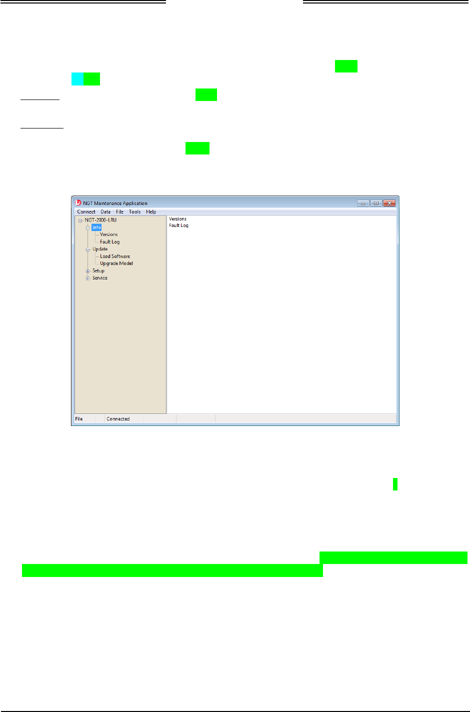
NGT-2000/2500
Installation Manual
Page 4-8 Maintenance 0040-170011-01
Prel-2014 Revision A
4.4.2 View or Retrieve Data
Use the NGT MAT to view versions and factory information and retrieve fault logs. See Figure 4-2. The
versions data and fault log can be saved to a file for later viewing or loading.
The Versions page shows the current software versions on the unit. Buttons on the bottom of the page
provide the user the options of ‘Refresh’, ‘Save’, and ‘Load’.
The Fault Log can be used for troubleshooting. Each fault is entered on its own indexed row, with details
for date, time, etc. Clicking on a row provides the user with additional information at the top of the page.
This information includes a fault description. Buttons on the bottom of the page provide the user the
options of ‘Refresh’, ‘Clear’, ‘Filter’, ‘Save’, ‘Load’, and ‘Export to CSV’. The fault data can be cleared
at the option of the user.
Figure 4-2 NGT MAT- Information
4.4.3 Configuration Restore
This procedure is used to automatically fill in the configuration options from a backup file. See Figure 4-3.
Perform the following procedure using a MPC and NGT MAT. This procedure assumes that the unit is in
Maintenance Mode and the MPC is interfaced to the unit using either the USB.
1. From the NGT MAT select SetupZ ConfigurationZ Restore.
2. Click on the Load button to ‘Load a Pre-Existing Configuration File’ to load the configuration
options windows. After the file is loaded into the NGT MAT, open a configuration window and click
on the Apply button to finish the update to the unit (see Note below). See instructions given in the
Installation Checkout section.
NOTE
The Tail Number and Mode S Identifier are unique for every aircraft. From
the NGT MAT select Setup Z Configuration Z Modify Z Aircraft and
enter the new data before pressing the Apply button.
DRAFT 3-2
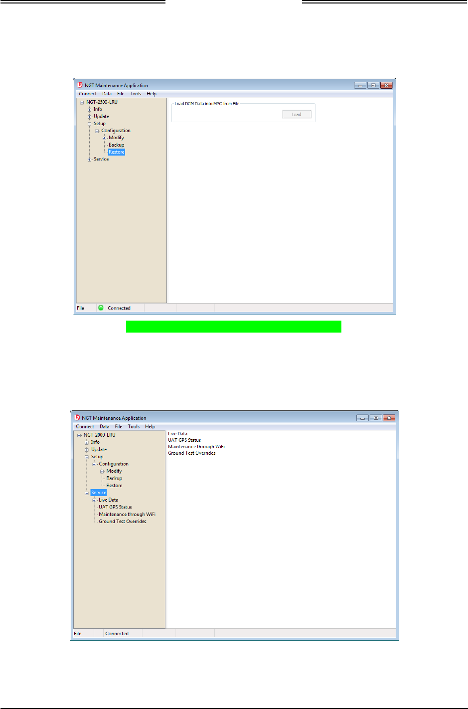
NGT-2000/2500
Installation Manual
0040-170011-01 Maintenance Page 4-9
Revision A Prel-2014
3. Validate the restoration of the configuration options by comparing the configuration data in the setup
pages with the log sheet for configuration and checkout created during initial installation.
Figure 4-3: NGT MAT – Restore Configuration
4.4.4 Service
This procedure is used to service and troubleshoot the NGT-2000/2500. See Figure 4-4. The Live Data
function is used for troubleshooting. Instructions on how to use live data are located in the Installation
Checkout section.
Figure 4-4: NGT MAT – Service
DRAFT 3-2

NGT-2000/2500
Installation Manual
Page 4-10 Maintenance 0040-170011-01
Prel-2014 Revision A
4.5 RETURN TO SERVICE
Use this section to validate the return to service of the NGT-2000/2500 and system components.
4.5.1 NGT-2000/2500
Use this procedure to remove and replace the NGT-2000/2500. The instructions herein are generic in
scope. The best established methods, techniques and practices should be used where no specific procedure
is given.
1. Removal Procedure
a. Ensure power to the unit is off.
b. Remove mating connector P2
c. Disconnect GPS and UAT L-band antenna connectors.
d. Loosen (4) screws.
e. Remove the unit from aircraft.
2. Installation Procedure
a. Ensure aircraft power is off.
b. Carefully place the unit in aircraft.
c. Connect mating connector P2.
d. Connect GPS and UAT L-band antenna. Be careful not to reverse those two antennas, as both are
TNC type connectors.
e. Secure the unit using (4) screws.
3. Functional Check Procedure
a. Apply power to the aircraft and the unit.
b. Configuration data is automatically loaded from the DCM.
c. Ensure no failure messages are annunciated on the controller/display/PED and fail lamp is OFF
after GPS has acquired a signal.
d. Perform the checkout procedure provided in the installation checkout to verify unit is functioning
correctly.
• Refer to the fault isolation section if errors are detected.
DRAFT 3-2

NGT-2000/2500
Installation Manual
0040-170011-01 Maintenance Page 4-11
Revision A Prel-2014
4.5.2 Configuration Module
Use this procedure to remove and replace the configuration module. The instructions herein are generic in
scope. The best established methods, techniques and practices should be used where no specific procedure
is given.
1. Removal Procedure
a. Disconnect P2 mating connector.
b. From the wire bundle remove tie wrap securing overbraid. Refer to installation section for
details on the P2 cable assembly.
c. Slide overbraid to expose module.
d. Remove module contacts from the P2 mating connector.
2. Installation Procedure
a. Insert contacts of new module into P2 mating connector.
Refer to installation guidelines for the module in the installation section for details on the module.
b. Slide overbraid back into position, and use a new tie wrap to secure overbraid.
c. Connect mating connector P2.
3. Functional Check Procedure
a. Cycle power to the NGT-2000/2500 system.
b. Use the installation checkout section to perform the select configuration options procedure or
use the maintenance sections configuration restore if the original configuration (.bin) file can be
retrieved from the original installer of the configuration module. If the original files cannot be
obtained use the log sheets in appendix C to help generate the information needed.
c. Perform the checkout procedure provided in the installation checkout to verify unit is
functioning correctly.
• Refer to the fault isolation section if errors are detected.
4.5.3 L-Band (UAT) Antenna
1. Refer to the aircraft manufacturer's data and the antenna manufacturer's installation instructions to
remove and replace the antenna(s).
a. Perform the checkout procedure provided in the installation checkout to verify unit is
functioning correctly.
• Refer to the fault isolation section if errors are detected.
4.5.4 GPS Antenna
1. Refer to the aircraft manufacturer's data and the antenna manufacturer's installation instructions to
remove and replace the antenna(s).
a. Perform the checkout procedure provided in the installation checkout to verify unit is
functioning correctly.
• Refer to the fault isolation section if errors are detected.
DRAFT 3-2

NGT-2000/2500
Installation Manual
Page 4-12 Maintenance 0040-170011-01
Prel-2014 Revision A
4.6 DISPOSITION OF FAILED ITEMS
1. The NGT-2000/2500 can only be repaired by a FAA Certified Repair Station Facility.
2. The configuration module cannot be repaired and must be replaced.
3. Return defective components to:
L-3 Avionics Systems
Attn: Customer Service
5353 52nd Street, S.E.
Grand Rapids, MI USA 49512-9704
4. Refer to the manufacturer’s data for external displays, controllers, and antennas interfaced to the NGT-
2000/2500.
5. If available, pack components in their original shipping container. If the original container is not
available, pack them as follows:
CAUTION
Do not use desiccant crystals when packaging electronic
assemblies. Since the assembly must be packed tightly, crystals
in bag form cannot be used. The use of loose crystals may
cause unnecessary damage resulting in a cleaning problem.
a. Ensure that conductive covers/caps are installed on the exposed terminals of connector, if
applicable.
b. LRU's that are marked as electrostatic discharge sensitive (ESDS) must be wrapped in static
protective materials.
c. Wrap with bubble pack. Secure bubble pack with reinforced tape.
d. Place assembly in a cardboard box.
e. Wrap any accessories in tissue and place in the box. Fill spaces with bubble pack.
f. Place an explanation letter in the box with the following information.
• Your name, address, and telephone number.
• Purchase order number.
• Description of component including, when applicable, model and serial number.
• A brief description of the difficulty.
g. Shut box, and seal with reinforced tape.
h. Attach packing list to outside of box.
DRAFT 3-2

NGT-2000/2500
Installation Manual
0040-170011-01 Appendix A Page A-1
Revision A Prel-2014
Appendix
A
NGT-2000/2500 Interface
Signal Name & Cable Characteristics
A.1 INTRODUCTION
This appendix defines the electrical characteristics of all input and output signal names to the NGT-
2000/2500 Multilink Surveillance System. Sufficient data is included to use a bus reader for the purpose
of identifying signal input and output characteristics and perform an electrical load analysis for the
aircraft. The input and output interfaces are sometimes configurable as noted in the following paragraphs.
The interface characteristics contained in this appendix are fully compatible with ARINC specifications
where noted. Connection information identifies the connector-pin and signal names as shown on the
external interconnect wiring diagram in the installation section.
A.2 INPUT AND OUTPUT INTERFACES
A.2.1 Input Power
The unit has two power inputs available for either +14 VDC or +28VDC operation (+9 to 36 VDC). Both
inputs are diode isolated within the unit and can transition between power inputs without interruption to
operation.
A.2.2 I2C Serial Bus (Configuration Module)
The I2C serial bus is used to communicate with the configuration module to store configuration options.
See Appendix C for a listing of options.
A.2.3 RF Suppression Bus
The transmission asserts a positive voltage on the output to provide the suppression to other L-band
equipment on the airplane. The suppression pulse output is DC coupled, and drives positive pulses not
less than 18 Vdc or greater than 70 Vdc into system loads from 300 to 2000 Ohms with a shunt
capacitance of up to 1850 pF. The signal meets the hardware characteristics as defined in ARINC 735B
Attachment 8.
A.2.4 Gillham Input (Altitude Input)
The Gillham interface is optional. Only one altimeter input source (gray code or RS-232) should be
connected. The Gillham interface consists of 11 discrete lines that are compliant with ARINC 718
requirements. These 11 discrete lines represent 11 binary digits representing the Gillham encoded
pressure altitude. The Gillham code uses a modified Gray code algorithm to ensure that no more than one
bit changes between adjacent altitudes. The three lowest significant bits represent 100 foot increments.
The eight highest significant bits represent 500 foot increments.
The digits are labeled as follows beginning with the most significant bit to the least significant bit (D2,
D4, A1, A2, A4, B1, B2, B4, C1, C2, & C4).
DRAFT 3-2

NGT-2000/2500
Installation Manual
Page A-2 Appendix A 0040-170011-01
Prel-2014 Revision A
A.2.5 ARINC 429 Output
The unit has one ARINC 429 Output that transmits data at high (100 kbps). ARINC 429 output is only
available via the NGT-2500 system. The NGT-2500 interfaces to a traffic display over the ARINC 429
bus using the standard traffic display (STIF) format as defined in ARINC 735 and the Display Traffic
Information File (DTIF) as described in ARINC 735B. The specific display format is configurable
through the configuration module.
A.2.5.1 ARINC 429 Output Labels
The following ARINC 429 labels are output to a Traffic Display on Bus #1:
• Label 13 - Control Panel Set
• Label 15 - Altitude Select Limits
• Label 16 - TCAS Mode/Sens
• Label 110 - Own Aircraft Latitude – Coarse
• Label 111 - Own Aircraft Longitude – Coarse
• Label 120 - Own Aircraft Latitude – Fine
• Label 121 - Own Aircraft Longitude – Fine
• Label 130 - Intruder Range
• Label 131 - Intruder Altitude
• Label 132 - Intruder Bearing
• Label 270 - Vert. Res. Adv.
• Label 274 - Selected Sensitivity Level (same as TXWORD 2)
• Label 203 - Own Aircraft Altitude (Uncorrected)
• Label 357 - RTS
• Label 350 - Maintenance
• Label 357 - ETX
• Label 377 - Equipment ID
A.2.6 Discrete Input
The NGT-2000/2500 has 4 discrete inputs that are set to GND/Open.
The discrete inputs provide 1.0 ± 0.25 mA of current when the input is grounded. The input is in the
ground state when input voltage is less than or equal to 3.5Vdc, or there is less than 10 Ohms impedance
to ground. The input is in the open state when the input voltage is greater than or equal to 18.0Vdc, or
there is greater than 100K Ohms impedance to ground. The discretes are dedicated or reserved as stated
below:
• Discrete 2 is used for IDENT command which is used to signal the NGT-2000/2500 to identify itself
with a unique 4-digit octal code. The discrete is set to GND/Open. Active position indicates IDENT
transmitted.
• Discrete 3 is used for On Ground status which used to determine whether ownship is in air or on
ground. The discrete is set to GND/Open. The active position indicates aircraft On Ground.
• Discrete 4 is used to turn ON/OFF the MSS Transmit function.
DRAFT 3-2
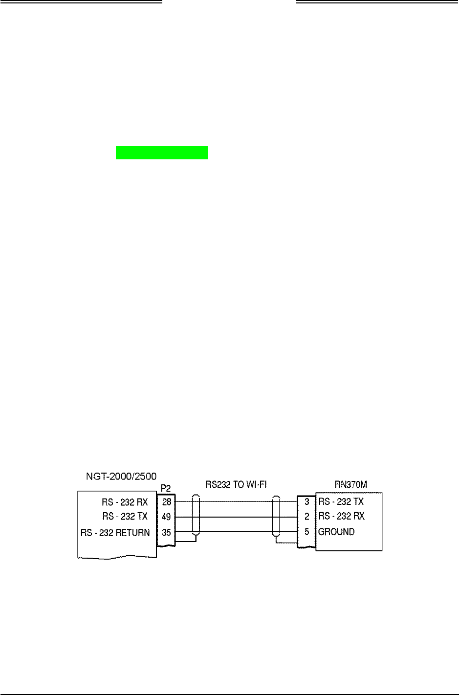
NGT-2000/2500
Installation Manual
0040-170011-01 Appendix A Page A-3
Revision A Prel-2014
A.2.7 Discrete Output
The NGT-2000/2500 has 4 discrete outputs that are set to GND/Open.
The ground logic state has an output voltage of < 3.0Vdc when sinking 250mA of current. The open logic
state has an output impedance of > 100K ohms to ground for voltages applied to the output of 0.0 to
36.0Vdc.
• Discrete 1 is used for ADS-B Failure. The discrete is set to GND/Open.
• Discrete 2 is used for RF suppression. The discrete is set to GND/Open.
• Discrete 4 is used for No ADS-B Coverage. The discrete is set to GND/Open.
A.2.8 RS-422 Interface
The RS-422 is a serial interface transmitting data from the NGT-2500 to an external weather display or
traffic display. This interface is optional depending on the installation. The data parameters are dependent
on the options set in the configuration module.
A.2.9 RS-232 Interface
The RS-232 is a serial interface used to receive and transmit altitude data, interface with Control Panel,
and interface with Wi-Fi Device. This interface is optional depending on the installation.
A.2.9.1 RS-232 WiFi Output
The RS-232 WiFi interface is optional. When configured the NGT-2000/2500 outputs the following
information to a WiFi connection:
• FIS-B Weather Data
• ADS-B Traffic Data
• Ownship Data
A.2.9.1.1 Compatible PED Interconnect Layout
Figure A-1 provides interconnect information for the RN370M PED Accessory.
Figure A-1: RN370M Interconnect Option for RS-232 to WiFi Converter
DRAFT 3-2

NGT-2000/2500
Installation Manual
Page A-4 Appendix A 0040-170011-01
Prel-2014 Revision A
A.3 PIN DEFINITION SUMMARY
Table A-1: Connector (P1) Pin Assignments
Pin Function Name Type* Pin Function Name Type*
1 NO CONNECTION G 32 DISC 1 IN RESERVED R
2 RS-422 INPUT A (-) FIS-B
(NGT-2500 ONLY) I 33 NO CONNECTION
3 RS-422 INPUT B (+) FIS-B
(NGT-2500 ONLY) I 34 GILLHAM ALTITUDE ENCODER (A4) I
4 3.3V RETURN FOR DCM (BLACK) C 35 GROUND S
5 RS-232 RX – CONTROL PANEL I 36 GILLHAM ALTITUDE ENCODER (C2) I
6 A429 OUT B (+) TRAFFIC DISPLAY
(NGT-2500 ONLY) O 37 DISC 3 OUT RESERVED R
7 RS-232 IN - ALTITUDE ENCODER I 38 NO CONNECTION S
8 NO CONNECTION S 39 RESERVED R
9 I2C DATA LINE FOR DCM (YELLOW) B 40 NO CONNECTION S
10 RESERVED R 41 14/28 V POWER RETURN 1 C
11 RF SUPPRESSION I/O B 42 +14/28VDC POWER IN 2 P
12 GILLHAM ALTITUDE ENCODER (D2) I 43 RESERVED R
13 GILLHAM ALTITUDE ENCODER (A1) I 44 RESERVED R
14 GILLHAM ALTITUDE ENCODER (B1) I 45 RESERVED R
15 GILLHAM ALTITUDE ENCODER (B4) I 46 NO CONNECTION S
16 GILLHAM ALTITUDE ENCODER (C4) I 47 RESERVED R
17 DISC 1 OUT – ADS-B FAIL INDICATOR O 48 NO CONNECTION S
18 NO CONNECTION S 49 RS-232 OUT – WIFI O
19 NO CONNECTION S 50 3.3V OUTPUT FOR DCM (RED) O
20 NO CONNECTION S 51 I2C CLOCK LINE FOR DCM (GREEN) I
21 +14/28VDC POWER IN 1 P 52 DISC 2 IN - IDENT I
22 RS-422 OUTPUT A (-) FIS-B
(NGT-2500 ONLY) O 53 DISC 3 IN – WEIGHT ON WHEELS /
AIR SPEED MONITOR I
23 RS-422 OUTPUT B (+)FIS-B
(NGT-2500 ONLY) O 54 GILLHAM ALTITUDE ENCODER (D4) I
24 NO CONNECTION S 55 GILLHAM ALTITUDE ENCODER (A2) I
25 RS-232 TX – CONTROL PANEL B 56 GILLHAM ALTITUDE ENCODER (B2) I
26 A429 OUT A (-) TRAFFIC DISPLAY
(NGT-2500 ONLY) O 57 GILLHAM ALTITUDE ENCODER (C1) I
27 NO CONNECTION S 58 NO CONNECTION S
28 RS-232 IN – WIFI I 59 DISC 4 OUT – NO ADS-B COVERAGE
O
29 NO CONNECTION S 60 NO CONNECTION S
30 DISC #4 - MSS TRANSMIT ON/OFF I 61 NO CONNECTION S
31 NO CONNECTION S 62 14/28 V POWER RETURN 2 C
* Signal Types: I = Signal Input O = Signal Output B = Bidirectional Signal P = Power Input
C = Common or Ground S = Spare Pin R = Reserved (Do Not Connect)
DRAFT 3-2

NGT-2000/2500
Installation Manual
0040-170011-01 Appendix A Page A-5
Revision A Prel-2014
A.4 CONNECTOR [J2]
PIN 1
Signal Name: Spare
Signal Function: Spare pin
Electrical Characteristics: ---
Connection: No Connection
Comments:
PIN 2
Signal Name: RS422_RX2A
Signal Function: RS-422 FIS-B Input
Electrical Characteristics: Data bits 8, Parity none, Stop bit 1, Start bit 1, Data
format is ASCII, Flow control is none.
Connection: Optional. 22 AWG twisted shielded pair wire
Comments: See paragraph A.2.6.
PIN 3
Signal Name: RS422_RX2B
Signal Function: RS-422 FIS-B Input
Electrical Characteristics: Data bits 8, Parity none, Stop bit 1, Start bit 1, Data
format is ASCII, Flow control is none.
Connection: Optional. 22 AWG twisted shielded pair wire.
Comments: See paragraph A.2.6.
PIN 4
Signal Name: DCM GND
Signal Function: SGND Serial Ground
Electrical Characteristics:
See paragraph A.2.9
Connection: Configuration Module – Black wire
Comments:
PIN 5
Signal Name: RS232_RX
Signal Function:
RS-232 Control Panel Interface
Electrical Characteristics: Data bits 8, Parity none, Stop bit 1, Start bit 1, Data
format is ASCII, Flow control is none.
Baud Rate: (configuration option) 1200, 2400, or 9600
bps. Depending on the equipment manufacturer
Connection: 22 AWG twisted shielded pair wire.
Comments: See paragraph A.2.5.
DRAFT 3-2

NGT-2000/2500
Installation Manual
Page A-6 Appendix A 0040-170011-01
Prel-2014 Revision A
PIN 6
Signal Name: TX_429B (ARINC 429_OUT B)
Signal Function: ARINC 429 Output for traffic display
Electrical Characteristics:
High Speed ARINC 429 (100 kbps)
Connection: 22 AWG twisted shielded pair wire
Comments:
See paragraph A.2.1
PIN 7
Signal Name: RS232_RX
Signal Function: Altitude Encoder RS-232 RX
Electrical Characteristics: Data bits (configuration option) 7 or 8, Parity none, Stop
bit 1, Start bit 1, Data format is ASCII, Flow control is
none. Baud Rate: (configuration option) 1200, 2400,
4800, 9600, 12000, 19200, 28800, 38400, 57600, or
115200 bps. Depending on the equipment manufacturer.
Connection:
22 AWG twisted shielded pair wire
Comments: See paragraph A.2.5
PIN 8
Signal Name: Spare
Signal Function: Spare pin
Electrical Characteristics: ---
Connection: No Connection
Comments:
PIN 9
Signal Name: DCM SDA
Signal Function: SDA Serial Data
Electrical Characteristics: See paragraph A.2.9.
Connection:
Configuration Module – Yellow wire
Comments:
PIN 10
Signal Name: RESERVED
Signal Function: DISC_ OUT 3
Electrical Characteristics: ---
Connection: No Connection
Comments:
DRAFT 3-2

NGT-2000/2500
Installation Manual
0040-170011-01 Appendix A Page A-7
Revision A Prel-2014
PIN 11
Signal Name: SUPPR_BUS
Signal Function: RF suppression input (DISC_OUT 2)
Electrical Characteristics:
Connection: Aircraft Suppression Bus. 22 AWG twisted shielded wire
Comments: See paragraph A.2.3
PIN 12
Signal Name: EXT_ALT_ENCODER[11]
Signal Function: Gillham Altitude Encoder (D2)
Electrical Characteristics: +30 V input max, < 1 mA sourced per line
Frequency: 20 Hz, Source Z: > 10 k ohm per line
Max Capacitance: < 20 pF per line
Connection: 22 AWG wire
Comments: See paragraph A.2.4
PIN 13
Signal Name: ALT_IN_A1
Signal Function: Gillham Altitude Encoder (A1)
Electrical Characteristics: +30 V input max, < 1 mA sourced per line
Frequency: 20 Hz, Source Z: > 10 k ohm per line
Max Capacitance: < 20 pF per line
Connection: 22 AWG wire
Comments: See paragraph A.2.4
PIN 14
Signal Name: ALT_IN_B1
Signal Function: Gillham Altitude Encoder (B1)
Electrical Characteristics: +30 V input max, < 1 mA sourced per line
Frequency: 20 Hz, Source Z: > 10 k ohm per line
Max Capacitance: < 20 pF per line.
Connection: 22 AWG wire
Comments: See paragraph A.2.4
PIN 15
Signal Name: ALT_IN_B4
Signal Function: Gillham Altitude Encoder (B4)
Electrical Characteristics: +30 V input max, < 1 mA sourced per line
Frequency: 20 Hz, Source Z: > 10 k ohm per line
Max Capacitance: < 20 pF per line.
Connection: 22 AWG wire
Comments: See paragraph A.2.4
DRAFT 3-2

NGT-2000/2500
Installation Manual
Page A-8 Appendix A 0040-170011-01
Prel-2014 Revision A
PIN 16
Signal Name: ALT_IN_C4
Signal Function: Gillham Altitude Encoder (C4)
Electrical Characteristics: +30 V input max, < 1 mA sourced per line
Frequency: 20 Hz, Source Z: > 10 k ohm per line
Max Capacitance: < 20 pF per line
Connection: 22 AWG wire
Comments: See paragraph A.2.4
PIN 17
Signal Name: DISC_OUT1 (Discrete Output No. 1)
Signal Function: ADS-B Fail Indicator
Electrical Characteristics: GND/Open (GND active)
Ground State < 3.0Vdc when sinking 250mA. Open State
has an impedance of >100K ohms to ground for voltages
applied to the output of 0.0 to 36.0Vdc.
Connection: Indicator Lamp. 22 AWG wire
Comments: See paragraph A.2.8
PIN 18
Signal Name: Spare
Signal Function: Spare pin
Electrical Characteristics: ---
Connection: No Connection
Comments:
PIN 19
Signal Name: Spare
Signal Function: Spare pin
Electrical Characteristics: ---
Connection: No Connection
Comments:
PIN 20
Signal Name: Spare
Signal Function: Spare pin
Electrical Characteristics: ---
Connection: No Connection
Comments:
DRAFT 3-2

NGT-2000/2500
Installation Manual
0040-170011-01 Appendix A Page A-9
Revision A Prel-2014
PIN 21
Signal Name: PWR_14_28VDC_IN
Signal Function: + 14/28 VDC Power IN 1
Electrical Characteristics: 8.9 watts nominal, 10.1 watts MAX
Connection: Aircraft 28V BUS. 22 AWG wire
Comments:
PIN 22
Signal Name: RS-422 Low
Signal Function: RS-422 FIS-B Output
Electrical Characteristics: Data bits 8, Parity none, Stop bit 1, Start bit 1, Data
format is ASCII, Flow control is none.
Baud Rate: (configuration option) 38400, 57600, or
115200. Depending on the equipment manufacturer
Connection: Optional. 22 AWG twisted shielded pair wire
Comments: See paragraph A.2.6.
PIN 23
Signal Name: RS-422 High
Signal Function: RS-422 FIS-B Output
Electrical Characteristics: Baud Rate: (configuration option) 38400, 57600, or
115200. Depending on the equipment manufacturer
Connection: Optional. 22 AWG twisted shielded pair wire.
Comments: See paragraph A.2.6.
PIN 24
Signal Name: Spare
Signal Function: Spare pin
Electrical Characteristics: ---
Connection: No Connection
Comments:
PIN 25
Signal Name: RS232_TX
Signal Function: RS-232 Control Panel Interface
Electrical Characteristics: Data bits 8, Parity none, Stop bit 1, Start bit 1, Data
format is ASCII, Flow control is none.
Baud Rate: (configuration option) 1200, 2400, or 9600
bps. Depending on the equipment manufacturer
Connection: 22 AWG twisted shielded pair wire
Comments: See paragraph A.2.5.
DRAFT 3-2

NGT-2000/2500
Installation Manual
Page A-10 Appendix A 0040-170011-01
Prel-2014 Revision A
PIN 26
Signal Name: TX_429A (ARINC 429_OUT A)
Signal Function: ARINC 429 Output for traffic display
Electrical Characteristics: High Speed ARINC 429 (100 kbps)
Connection: 22 AWG twisted shielded pair wire
Comments: See paragraph A.2.1
PIN 27
Signal Name: Spare
Signal Function: Spare pin
Electrical Characteristics: ---
Connection: No Connection
Comments:
PIN 28
Signal Name: RS232_RX
Signal Function: RS-232 PED/Wi-Fi Device
Electrical Characteristics: Data bits 8, Parity none, Stop bit 1, Start bit 1, Data
format is ASCII, Flow control is none. Baud Rate: 115200
bps.
Connection: Optional. 22 AWG twisted shielded pair wire
Comments: See paragraph A.2.5.
PIN 29
Signal Name: Spare
Signal Function: Spare pin
Electrical Characteristics: ---
Connection: No Connection
Comments:
PIN 30
Signal Name: EXT_ADSB_ON_OFF
Signal Function: Discrete Input. MSS Transmit ON/OFF
Electrical Characteristics: Open = Invalid, = +27.5 Vdc at the input OR a resistance
of greater than 100k Ohms to ground.
Ground = Valid, < 3.5 Vdc at the input OR a resistance of
less than 10 Ohms to ground.
Connection: 22 AWG twisted shielded pair wire
Comments: See paragraph A.2.5.
DRAFT 3-2

NGT-2000/2500
Installation Manual
0040-170011-01 Appendix A Page A-11
Revision A Prel-2014
PIN 31
Signal Name: Spare
Signal Function: Spare pin
Electrical Characteristics: ---
Connection: No Connection
Comments:
PIN 32
Signal Name: DISC_IN1 (Discrete Input No. 1)
Signal Function: Audio Mute (Future Option)
Electrical Characteristics: GND/Open (GND active)
Ground State < 3.5Vdc, Open State ≥ 18Vdc
Connection: Momentary Switch. 22 AWG wire
Comments: See paragraph A.2.7
PIN 33
Signal Name: Spare
Signal Function: Spare pin
Electrical Characteristics: ---
Connection: No Connection
Comments:
PIN 34
Signal Name: ALT_IN_A4
Signal Function: Gillham Altitude Encoder (A4)
Electrical Characteristics: +30 V input max, < 1 mA sourced per line
Frequency: 20 Hz, Source Z: > 10 k ohm per line
Max Capacitance: < 20 pF per line
Connection: See paragraph A.2.4
22 AWG wire
Comments:
PIN 35
Signal Name: RS-232 RETURN
Signal Function: Signal Ground
Electrical Characteristics: Electrical Ground
Connection: Black wire
Comments: See paragraph A.2.5.
DRAFT 3-2

NGT-2000/2500
Installation Manual
Page A-12 Appendix A 0040-170011-01
Prel-2014 Revision A
PIN 36
Signal Name: ALT_IN_C2
Signal Function: Gillham Altitude Encoder (C2)
Electrical Characteristics: +30 V input max, < 1 mA sourced per line
Frequency: 20 Hz, Source Z: > 10 k ohm per line
Max Capacitance: < 20 pF per line.
Connection: 22 AWG wire
Comments: See paragraph A.2.4.
PIN 37
Signal Name: DISC_OUT3 (Discrete Output No. 3)
Signal Function: Spare pin
Electrical Characteristics: ---
Connection: No Connection
Comments:
PIN 38
Signal Name: Spare
Signal Function: Spare pin
Electrical Characteristics: ---
Connection: No Connection
Comments:
PIN 39
Signal Name: Spare
Signal Function: Spare pin
Electrical Characteristics: ---
Connection: No Connection
Comments:
PIN 40
Signal Name: Spare
Signal Function: Spare pin
Electrical Characteristics: ---
Connection: No Connection
Comments:
DRAFT 3-2

NGT-2000/2500
Installation Manual
0040-170011-01 Appendix A Page A-13
Revision A Prel-2014
PIN 41
Signal Name: Ground
Signal Function: 14/28 V Power Return 1
Electrical Characteristics: -------
Connection: Aircraft 28V Return BUS. 22 AWG wire
Comments:
PIN 42
Signal Name: PWR_14_28Vdc_IN
Signal Function: + 14/28 Vdc Power IN 2
Electrical Characteristics: 8.9 watts nominal, 10.1 watts MAX
Connection: Aircraft 14/28V BUS. 22 AWG wire
Comments:
PIN 43
Signal Name: Audio Ground
Signal Function: Audio Out 600 Ohm L
Electrical Characteristics: Ground
Connection:
Audio Panel. 22 AWG twisted shielded pair wire
Comments: Future Option
PIN 44
Signal Name: AUDIO OUT #1
Signal Function: Audio Out 4-600 Ohm H
Electrical Characteristics: 40 milli Watts (RMS) at 1000 Hz into a 600 Ohm audio
distribution system.
Connection: Audio Panel. 22 AWG twisted shielded pair wire
Comments: Future Option
PIN 45
Signal Name: AUDIO Out #2
Signal Function: Audio Out 4-600 Ohm
Electrical Characteristics: 40 milli Watts (RMS) at 1000 Hz into a 600 Ohm audio
distribution system.
Connection: SPARE
Comments: Future Option
DRAFT 3-2

NGT-2000/2500
Installation Manual
Page A-14 Appendix A 0040-170011-01
Prel-2014 Revision A
PIN 46
Signal Name: Spare
Signal Function: Spare pin
Electrical Characteristics:
---
Connection: No Connection
Comments:
PIN 47
Signal Name: Spare
Signal Function: Spare pin
Electrical Characteristics:
---
Connection: No Connection
Comments:
PIN 48
Signal Name: Spare
Signal Function: Spare pin
Electrical Characteristics: ---
Connection: No Connection
Comments:
PIN 49
Signal Name: RS232_TX
Signal Function: RS-232 PED/Wi-Fi Device
Electrical Characteristics: Data bits 8, Parity none, Stop bit 1, Start bit 1, Data
format is ASCII, Flow control is none. Baud Rate: 115200
bps.
Connection: Optional. 22 AWG twisted shielded pair wire
Comments: See paragraph A.2.5
PIN 50
Signal Name: DCM 3.3V
Signal Function: SPWR Serial Power (3.3 Vdc Power), 50ma max
Electrical Characteristics: See paragraph A.2.9
Connection: Configuration Module – red wire
Comments:
DRAFT 3-2

NGT-2000/2500
Installation Manual
0040-170011-01 Appendix A Page A-15
Revision A Prel-2014
PIN 51
Signal Name: DCM SCL
Signal Function: SCL Serial Clock
Electrical Characteristics: See paragraph A.2.9
Connection: Configuration Module – green wire
Comments:
PIN 52
Signal Name: DISC_IN2 (Discrete Input No. 2)
Signal Function: IDENT
Electrical Characteristics: GND/Open (GND active)
Ground State < 3.5Vdc, Open State ≥ 18Vdc
Connection: Momentary Switch. 22 AWG wire
Comments: See paragraph A.2.7
PIN 53
Signal Name: DISC_IN3 (Discrete Input No. 3)
Signal Function: Gear/Squat Air Speed Monitor
Electrical Characteristics: GND/Open (GND active)
Ground State < 3.5Vdc, Open State ≥ 18Vdc
Connection: 22 AWG wire. On/Off Switch
Comments: See paragraph A.2.7.
PIN 54
Signal Name: ALT_IN_D4
Signal Function: Gillham Altitude Encoder
Electrical Characteristics: +30 V input max, < 1 mA sourced per line
Frequency: 20 Hz, Source Z: > 10 k ohm per line
Max Capacitance: < 20 pF per line
Connection: 22 AWG wire
Comments: See paragraph A.2.4.
PIN 55
Signal Name: ALT_IN_A2
Signal Function: Gillham Altitude Encoder (A2)
Electrical Characteristics: +30 V input max, < 1 mA sourced per line
Frequency: 20 Hz, Source Z: > 10 k ohm per line
Max Capacitance: < 20 pF per line
Connection: 22 AWG wire
Comments: See paragraph A.2.4.
DRAFT 3-2

NGT-2000/2500
Installation Manual
Page A-16 Appendix A 0040-170011-01
Prel-2014 Revision A
PIN 56
Signal Name: ALT_IN_B2
Signal Function: Gillham Altitude Encoder (B2)
Electrical Characteristics: +30 V input max, < 1 mA sourced per line
Frequency: 20 Hz, Source Z: > 10 k ohm per line
Max Capacitance: < 20 pF per line.
Connection: 22 AWG wire
Comments: See paragraph A.2.4.
PIN 57
Signal Name: ALT_IN_C1
Signal Function: Gillham Altitude Encoder (C1)
Electrical Characteristics: +30 V input max, < 1 mA sourced per line
Frequency: 20 Hz, Source Z: > 10 k ohm per line
Max Capacitance: < 20 pF per line.
Connection: 22 AWG wire
Comments: See paragraph A.2.4.
PIN 58
Signal Name: DISC_OUT4 (Discrete Output No. 4)
Signal Function: No ADS-B Coverage
Electrical Characteristics: GND/Open (GND active)
Ground State < 3.0Vdc when sinking 250mA. Open State
has an impedance of >100K ohms to ground for voltages
applied to the output of 0.0 to 36.0Vdc.
Connection: Indicator Lamp. 22 AWG wire
Comments: See paragraph A.2.8.
PIN 59
Signal Name: Spare
Signal Function: Spare pin
Electrical Characteristics:
---
Connection: No Connection
Comments:
PIN 60
Spare Signal Name:
Spare pin
Signal Function:
--- Electrical Characteristics:
No Connection Connection:
Comments:
DRAFT 3-2

NGT-2000/2500
Installation Manual
0040-170011-01 Appendix A Page A-17
Revision A Prel-2014
PIN 61
Signal Name: Spare
Signal Function:
Spare pin
Electrical Characteristics: ---
Connection: No Connection
Comments:
PIN 62
Signal Name: Ground
Signal Function: 14/28 V Power Return 1
Electrical Characteristics: ----
Connection: Aircraft 14/28V Return BUS
Comments:
DRAFT 3-2

NGT-2000/2500
Installation Manual
Page A-18 Appendix A 0040-170011-01
Prel-2014 Revision A
This page intentionally blank
DRAFT 3-2

NGT-2000/2500
Installation Manual
0040-170011-01 Appendix B Page B-1
Revision A Prel-2014
Appendix
B
Environmental Qualification Form
B.1 INTRODUCTION
This appendix includes the environmental qualifications form required for the NGT-2000/2500 Multilink
Surveillance System and Configuration Module.
B.2 ENVIRONMENTAL QUALIFICATION FORM
(Reference Document 8008647 Rev.G-5)
PRODUCT DESCRIPTION: Multilink Surveillance System
MODEL: NGT-2000/2500
PART NO.: 9022500-10000
MANUFACTURER: Aviation Communication and Surveillance Systems
ADDRESS: ACSS 19810 N. 7th Avenue Phoenix, AZ 85027-4741
PRODUCT DESCRIPTION:: Configuration Module
PART NUMBERS: 9230-17003-01
MANUFACTURER: Aviation Communication and Surveillance Systems
ADDRESS: ACSS 19810 N. 7th Avenue Phoenix, AZ 85027-4741
REVISION & CHANGE NUMBER OF DO-160: G
CONDITION SECTION/PARAGRAPH TEST DESCRIPTION
Temperature and Altitude 4.0 Equipment tested to Category B2.
Low Temperature 4.5.1&4.5.2 Equipment tested to Category B2.
High Temperature 4.5.3&4.5.4 Equipment tested to Category B2.
In-Flight Loss of Cooling 4.5.4 Equipment Not Tested, External
Cooling Not Required
Altitude 4.6.1 Tested Operating Altitude of
25,000'
B2
Decompression 4.6.2 N/A
Overpressure 4.6.3 N/A
Temperature Variation 5.0 Equipment tested to Category B.
Humidity 6.0 Equipment tested to Category B.
Operational Shocks, and Crash Safety 7.0 Except Operation Shock tested to
20G's
Category B2.
Vibration 8.0 For fixed wing, Cat S Curve L and
DRAFT 3-2

NGT-2000/2500
Installation Manual
Page B-2 Appendix B 0040-170011-01
Prel-2014 Revision A
CONDITION SECTION/PARAGRAPH TEST DESCRIPTION
Cat R Curve C/C1.
For Helicopter, Cat U2 Curve
F/F1
Explosion Proofness 9.0 Equipment tested to Category X.
No test performed.
Waterproofness 10.0 Equipment tested to Category X.
No test performed.
Fluids Susceptibility 11.0 Equipment identified as Category
X, No test performed.
Sand and Dust 12.0 Equipment identified as Category
X, No test performed.
Fungus Resistance 13.0 Equipment identified as Category
X, No test performed.
Salt Spray 14.0 Equipment identified as Category
X, No test performed.
Magnetic Effect 15.0 Equipment tested to Category Z.
Power Input 16.0 Equipment tested to Category
BXX.
Voltage Spike 17.0 Equipment tested to Category A.
Audio Frequency Conducted
Susceptibility
18.0 Equipment tested to Category B.
Induced Signal Susceptibility 19.0 Equipment tested to Category ZC.
Radio Frequency Susceptibility 20.0 Equipment tested to Category TT.
Emission of Radio Frequency Energy 21.0 Equipment tested to Category L.
Lightning Induced Transient
Susceptibility
22.0 Equipment tested to Category
A3J3L3.
Lightning Direct Effects 23.0 Equipment identified as Category
X, No test performed.
Icing 24.0 Equipment identified as Category
X, No test performed.
Electrostatic Discharge 25.0 Equipment tested to Category A.
Other Tests None.
DRAFT 3-2

NGT-2000/2500
Installation Manual
0040-17011-01 Appendix C Page C-1
Revision A Prel-2014
Appendix
C
Configuration and Checkout Log
Date: ______________ By:__________________________________
Installation Information
(use the information found in the general information section to help fill out the following data)
d Model NGT-2000 P/N 9022000-10000 d Model NGT-2500 P/N 9022000-10000
Unit S/N: ________________________ Mod Level: ______________________
Aircraft Model: ___________________ Aircraft S/N: _____________________
Operation S/W: ___________________ Firmware S/W: ___________________
Configuration
Aircraft Options
Call Sign: _______________________________
ICAO Address (Octal): ____________________
VFR Code (Octal): ________________________
Aircraft Emitter Category: _______
Aircraft Length (meters): ________
Aircraft Width (meters): _________
Aircraft ground speed threshold in air (knots): _______
Aircraft ground speed threshold on ground (knots): _______
Altitude threshold A/G Status (feet): _______
GPS Antenna Offset Lateral (feet): _______
GPS Antenna Offset Longitudinal (feet): _______
GPS Antenna Offsets Vertical (feet): _______
Audio Volume: _______
Table C-1: Log Sheet for Configuration and Checkout
(Sheet 1 of 2)
DRAFT 3-2

NGT-2000/2500
Installation Manual
Page C-2 Appendix C 0040-17011-01
Prel-2014 Revision A
Altitude
Baro Altitude Source: ( d RS-232 d Gilham Code)
NIC BARO ( d No altitude integrity d Altitude is non-Gilham or crosschecked)
Altitude Source Protocol ( d Trimble/Garmin/Icarus d Magellan d UPS AT
d UPS AT Loran 618 d Northstar d Shadin d ARNAV
Pressure Altitude Baud Rate (d 1200 d 2400 d 4800 d 9600)
Altitude Resolution (ft): d 1 foot d 100 feet
Config Settings 1
CSID Logic ( d Disabled d Enabled)
TSAA ( d Disabled d Enabled)
ARINC Format ( d STIF d DTIF d Both)
GPS Antenna Direction ( d Left d Right)
Config Settings 3
Control Panel Type ( d None d Via RS-422 (MX20/GMX200) d SL70/GSL71 (RS-232)
d GTX 327 or GTX 330 (RS-232 d L-3 UAT Control Panel 1
RS-232 Control Panel Baud Rate Override d 1200 d 9600 (default)
Anonymous Mode ( d Not Available d Available)
Pilot Entry of Flight ID ( d Disabled d Enabled)
Air/Ground Indication ( d Ground on Ground d On Ground Open d Not Used)
RS-422 Options
Interface Options ( d None d MX20 d GMX200 Traffic Alert)
Baud Rate ( d 38400 57600 d 115200)
Uplinks ( d 0 uplinks per second d 2 uplinks per second d 4 uplinks per seconds)
RS-232 Options
WiFi Baud Rate ( d 38400 d 57600 d 115200)
WiFi Accessory Configuration
WiFi Module SSID: Wifly-GSX- _____
Table C-1: Log Sheet for Configuration and Checkout
(Sheet 2 of 2
DRAFT 3-2