Aviation Communications and Surveillance Systems MSS90 Multi Link Transponder User Manual Installation Manual
Aviation Communications and Surveillance Systems (ACSS), LLC. Multi Link Transponder Installation Manual
UserManual.wiki
>
Aviation Communications and Surveillance Systems
>
MSS90 User Manual
Installation Manual
Navigation menu
Upload a User Manual
Namespaces
Wiki Guide
HTML
PDF
Info
Views
User Manual
Discussion / Help
Navigation
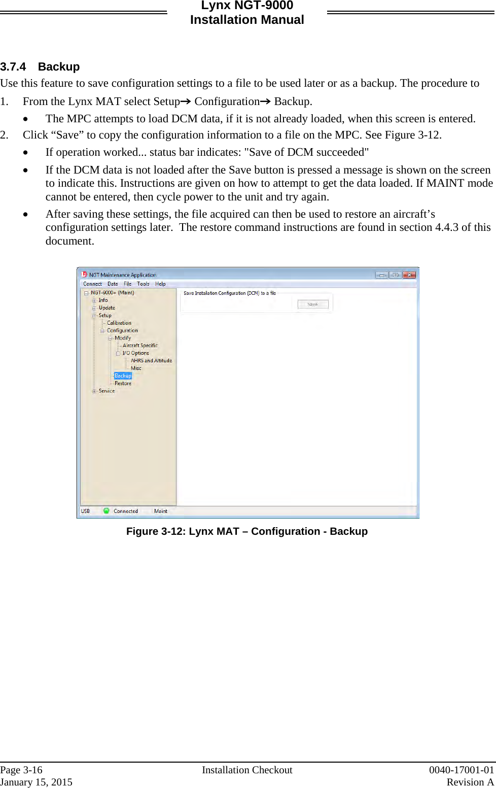
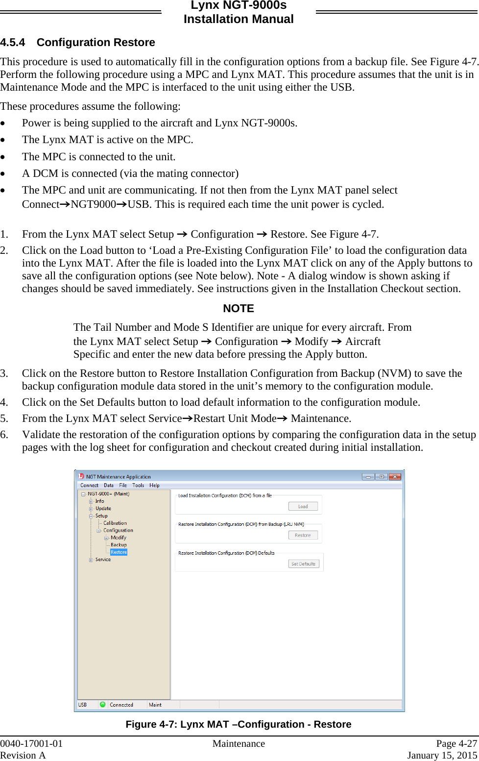
![Lynx NGT-9000s Installation Manual List of Effective Pages Dates of original and changed pages are: Revision A .............................. January 15, 2015 Total number of pages in this publication consists of the following: Title page Page A i thru xvi 1-1 thru 1-40 2-1 thru 2-30 3-1 thru 3-34 4-1 thru 4-32 A-1 thru A-24 B-1 thru B-4 C-1 thru C-2 Disclaimer This Installation Manual contains information that is considered relevant only at the time of distribution with the Avionics Systems product for which it is shipped. Information in this manual is subject to change without notice and will not be updated after distribution. Avionics Systems does provide a listing of all publications and directives with their current revision and change levels to insure up-to-date information. See www.as.l-3com.com, Customer Care Section, Technical Publications Page for the Publications Index to get an up-to-date listing of all Avionics Systems technical publications and directives. Contact Avionics Systems Customer Service [1-800-453-0288] to determine availability of technical publications and directives. Revision A Highlights Original release. Page ii 0040-17001-01 January 15, 2015 Revision A](https://usermanual.wiki/Aviation-Communications-and-Surveillance-Systems/MSS90/User-Guide-2530994-Page-4.png)

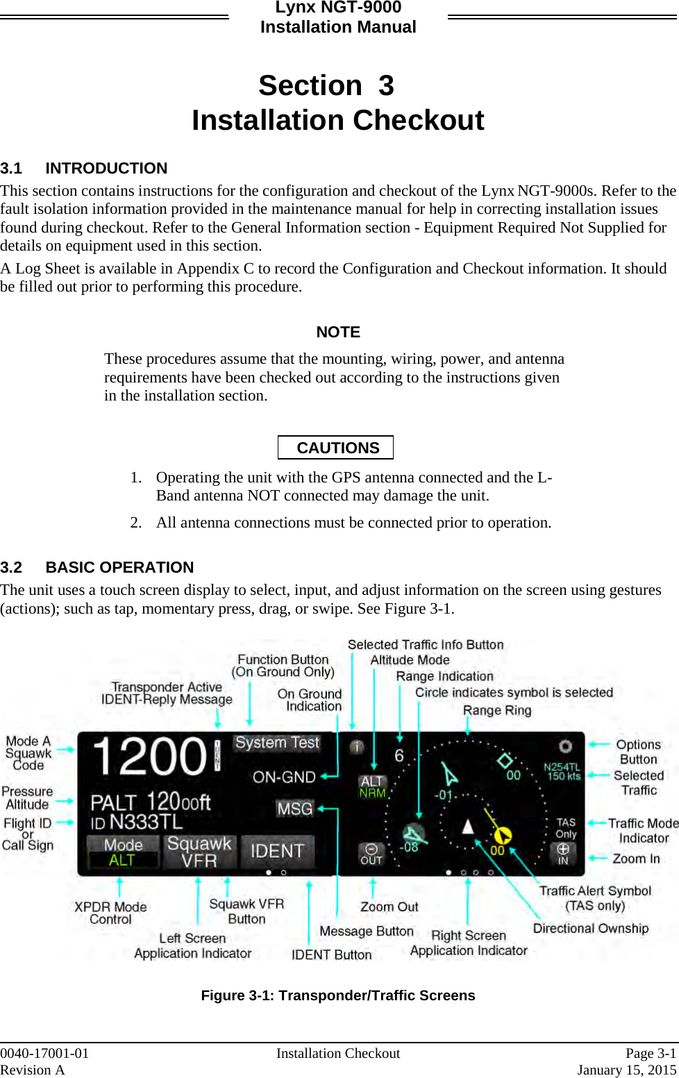
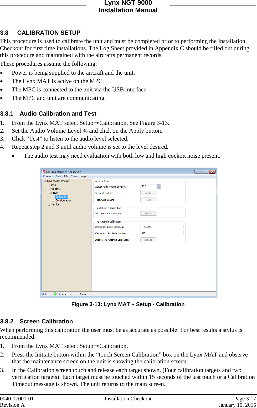
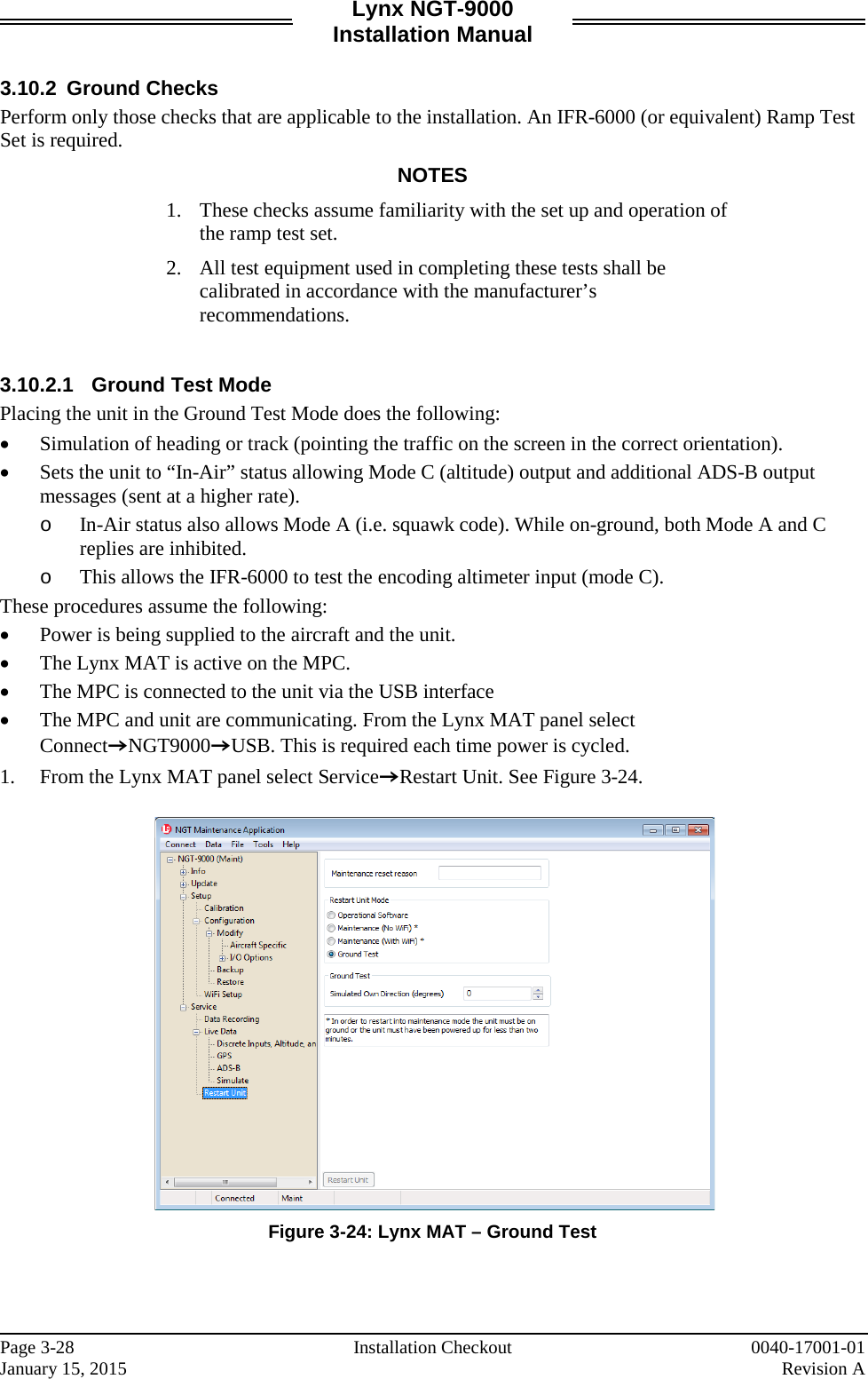
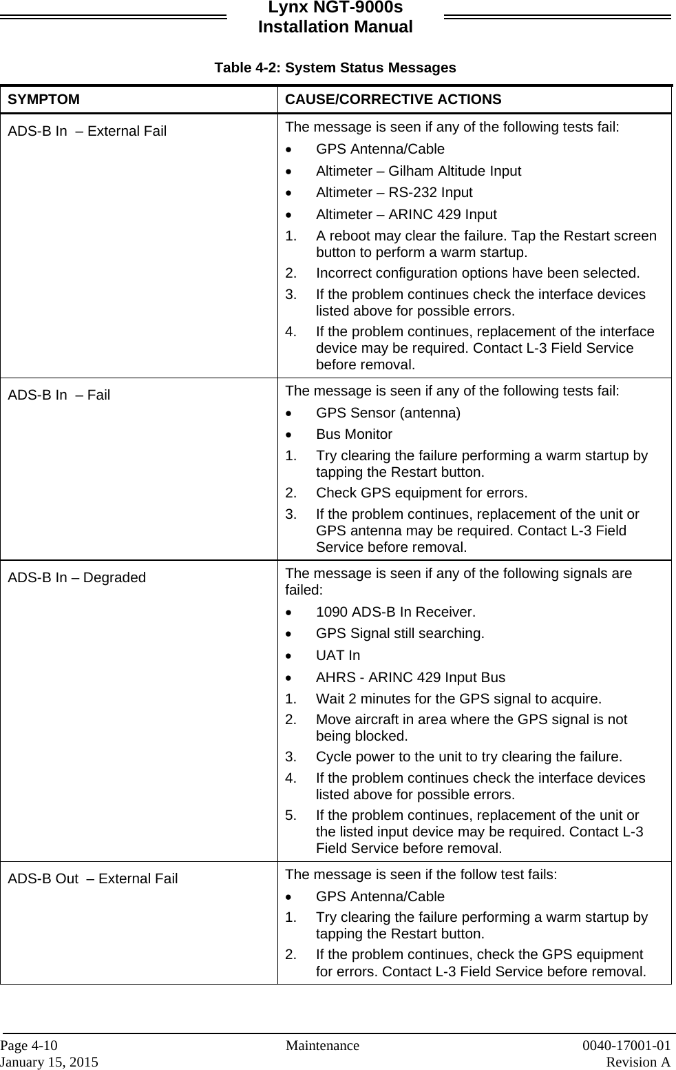
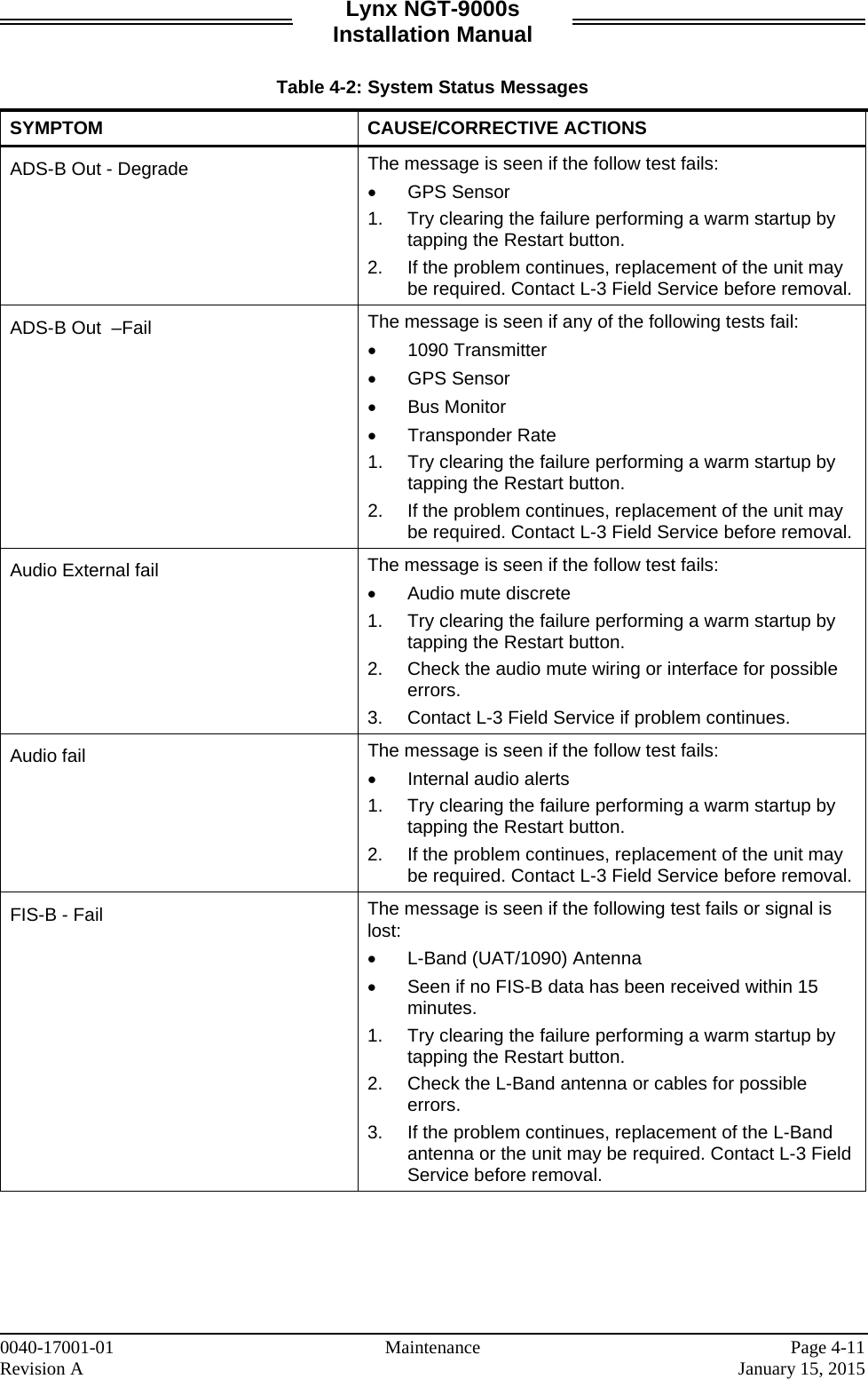
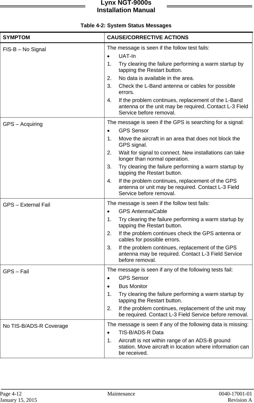
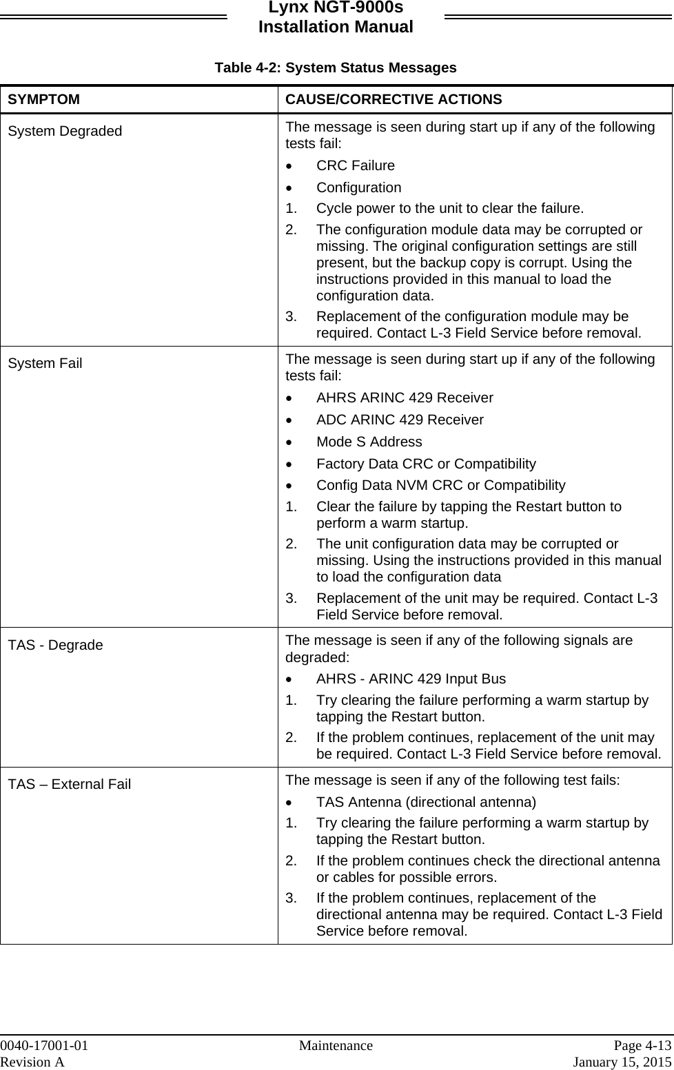
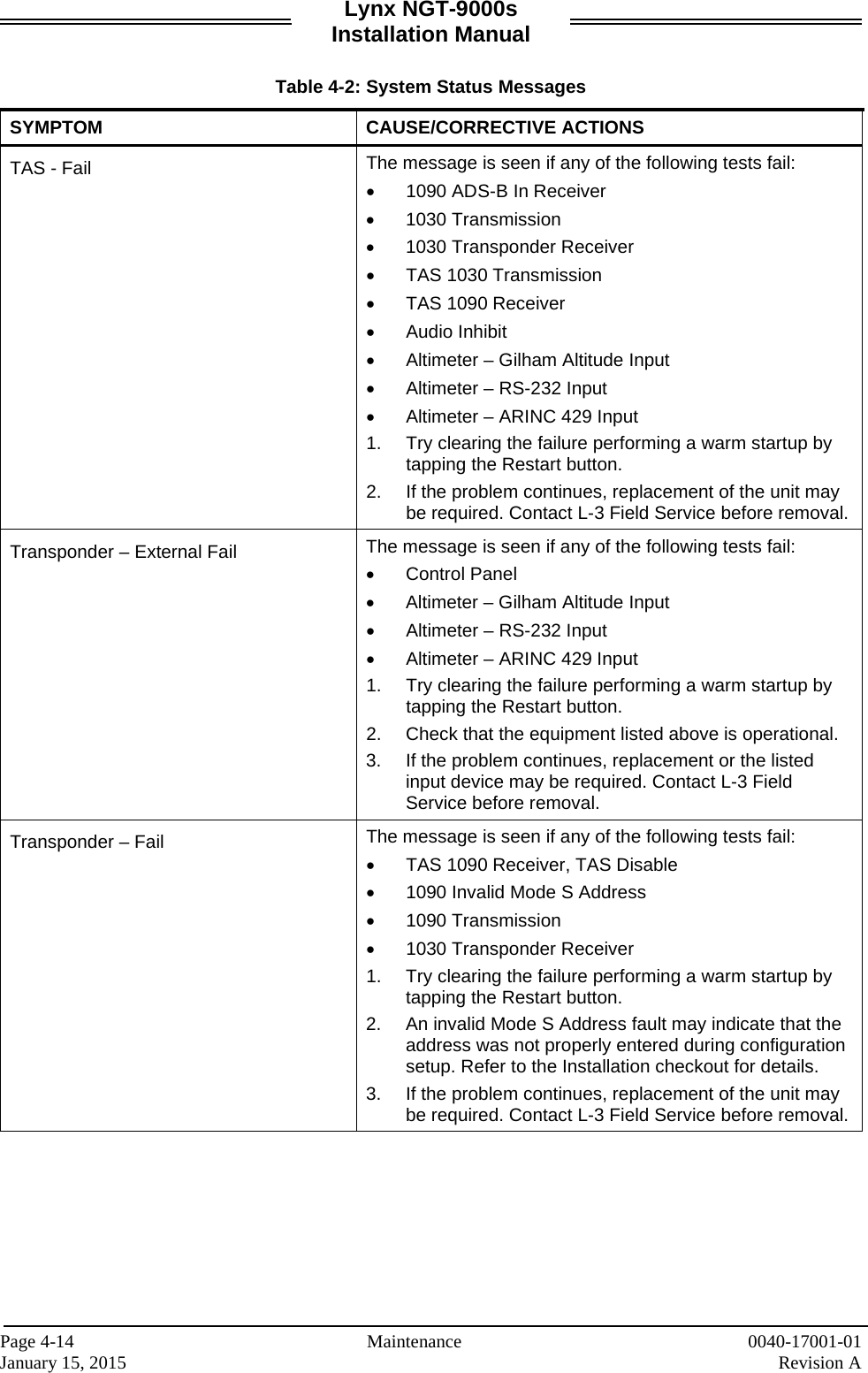
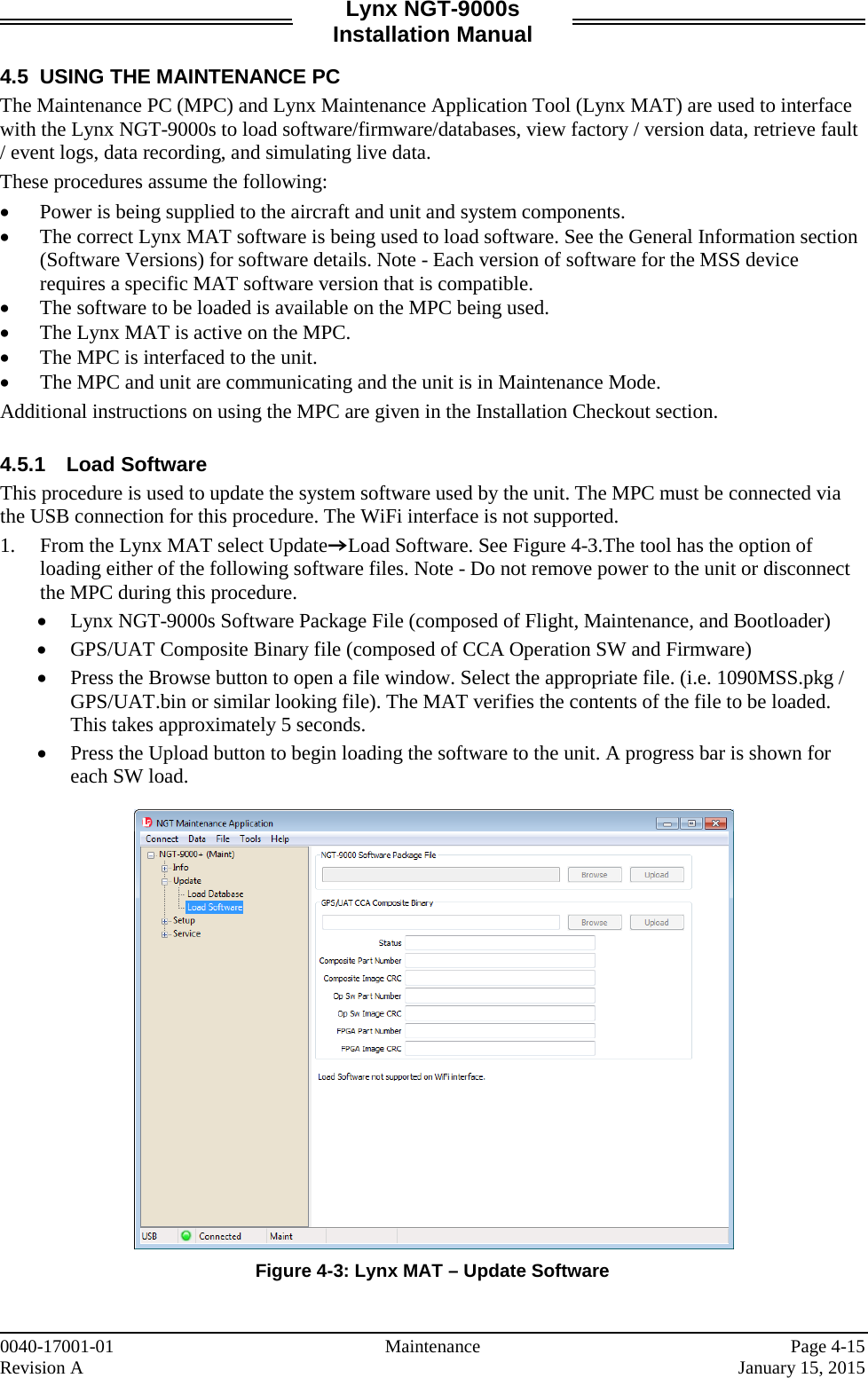
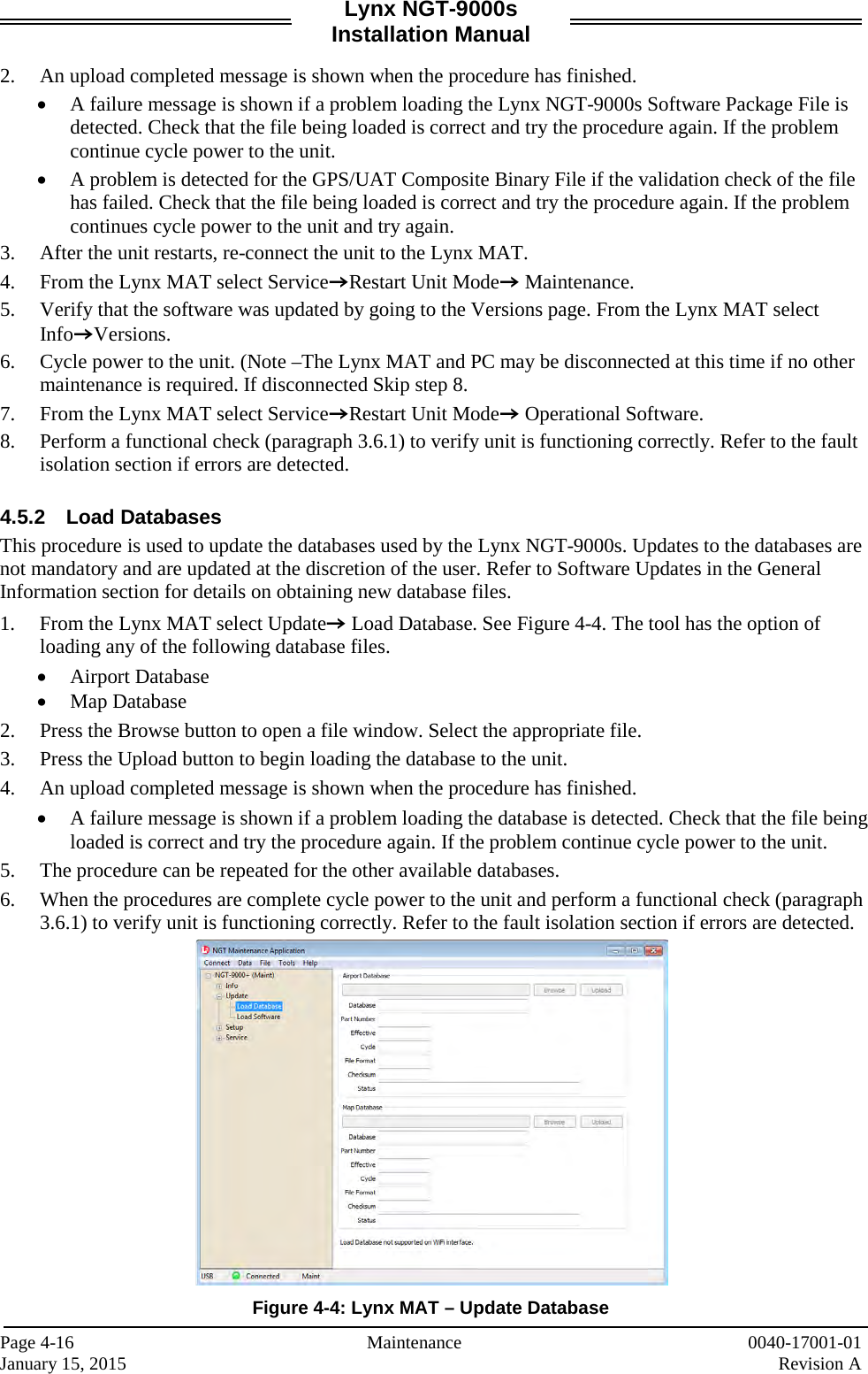
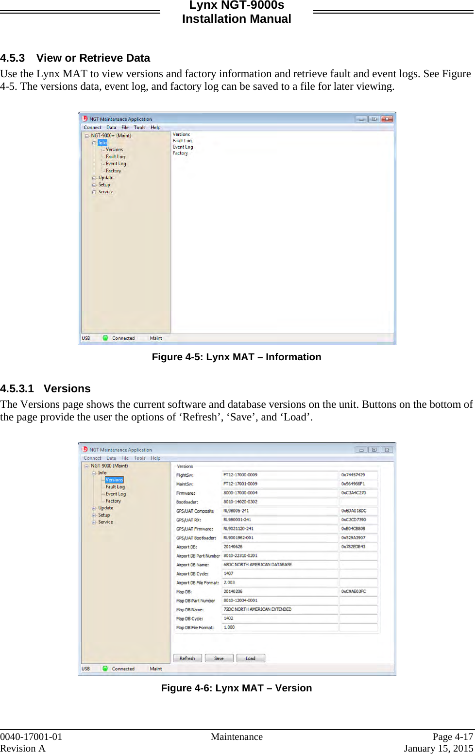
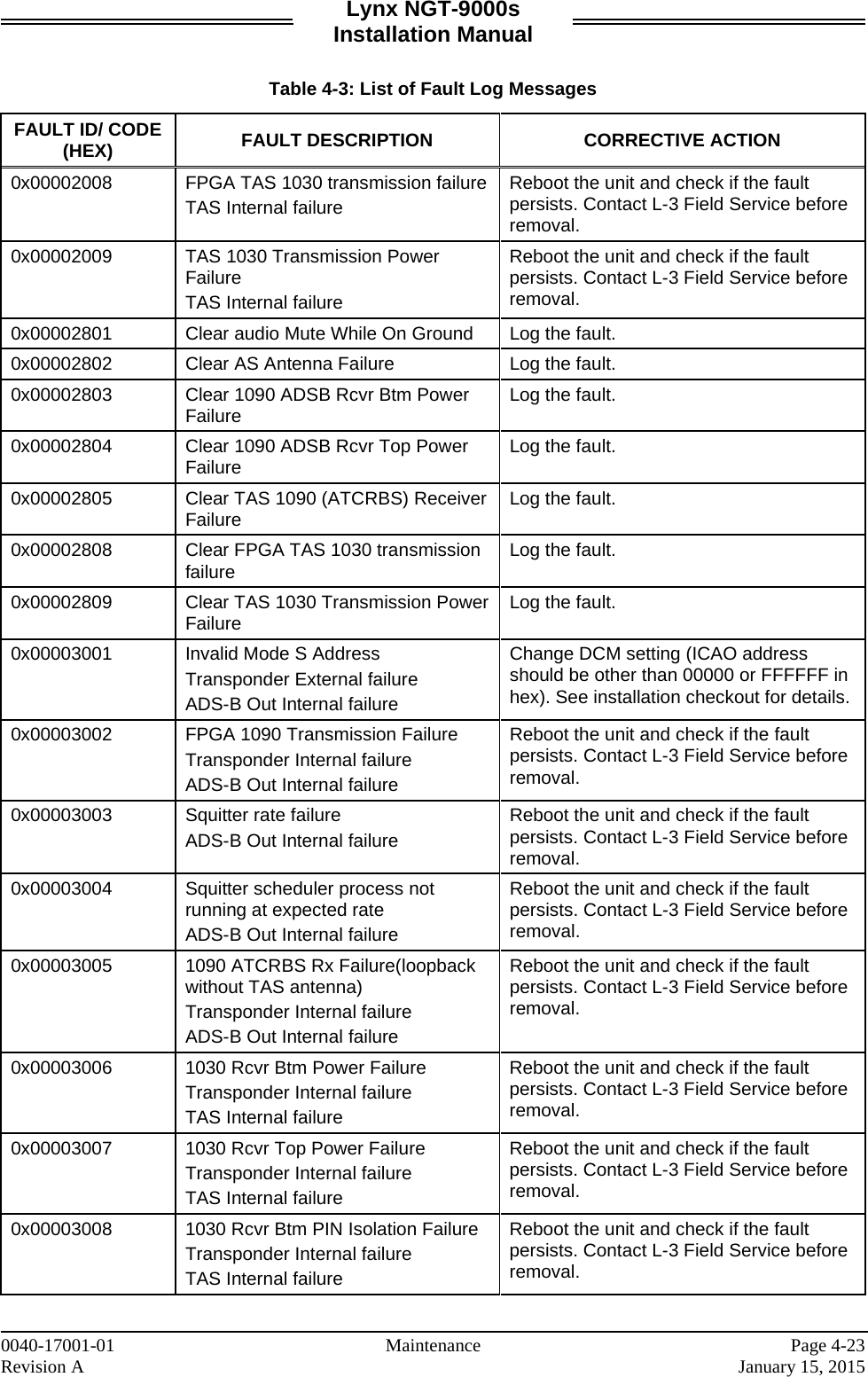
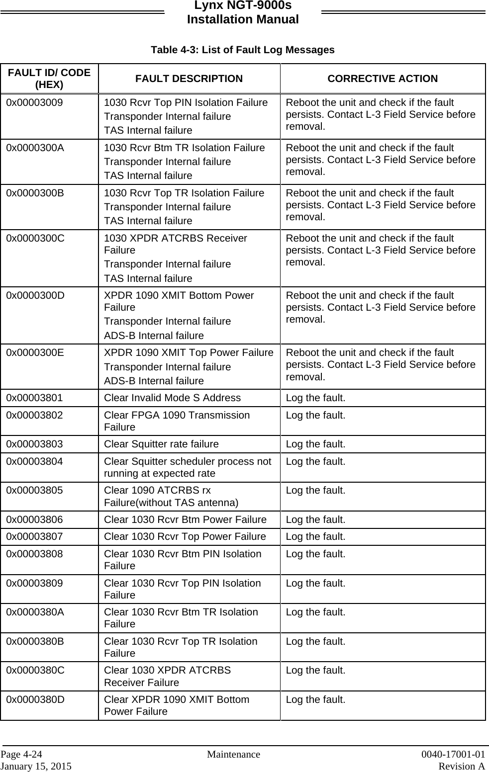
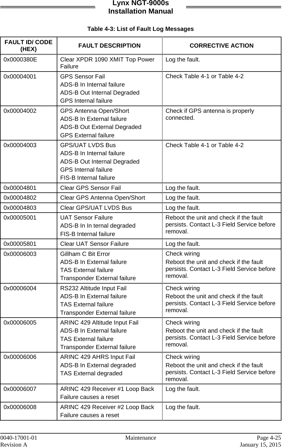
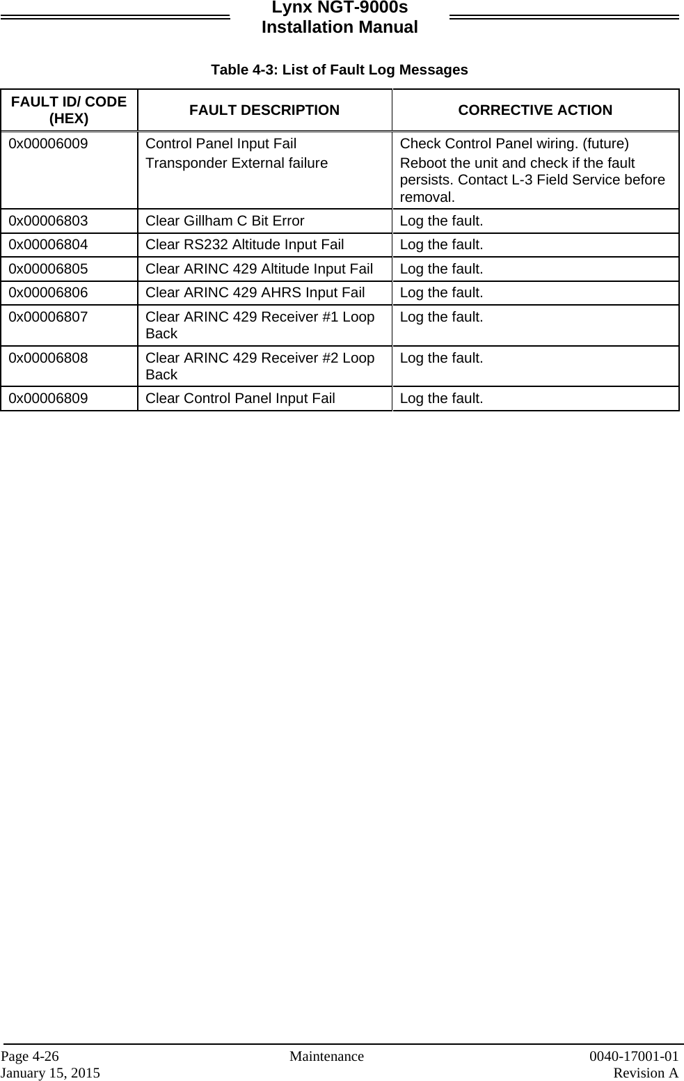
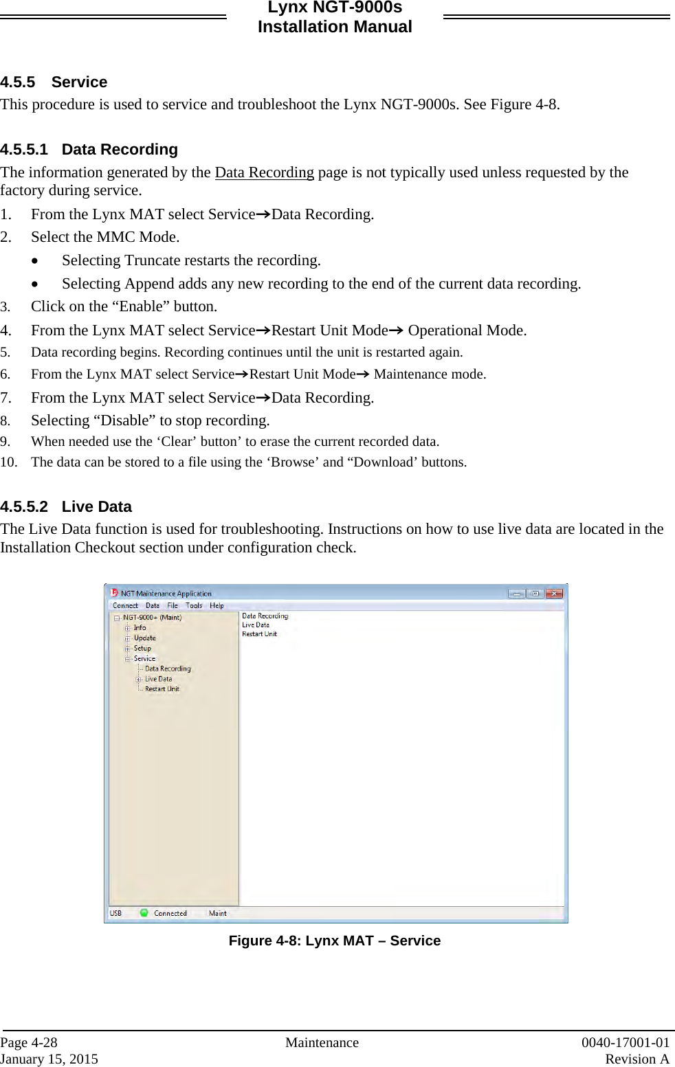
![Lynx NGT-9000s Installation Manual Table of Contents (continued) Paragraph Page 3.10 Installation Checkout ................................................................................................................ 3-23 3.10.1 Functional Checks .................................................................................................................... 3-23 3.10.2 Ground Checks ......................................................................................................................... 3-28 3.10.3 Electromagnetic Interference (E.M.I.) Check ........................................................................... 3-31 3.10.4 Display Check ........................................................................................................................... 3-33 3.10.5 Flight Test ................................................................................................................................. 3-33 3.10.6 Installation Checkout Complete ................................................................................................ 3-33 Section 4 Maintenance 4.1 Introduction ................................................................................................................................. 4-1 4.2 Continued Airworthiness............................................................................................................. 4-1 4.3 Periodic Maintenance ................................................................................................................. 4-1 4.3.1 Screen Calibration ...................................................................................................................... 4-2 4.3.2 Directional Antenna (NY156 and NY164)................................................................................... 4-3 4.4 Fault Isolation ............................................................................................................................. 4-3 4.4.1 System Status Messages ......................................................................................................... 4-10 4.5 Using the Maintenance PC ....................................................................................................... 4-16 4.5.1 Load Software .......................................................................................................................... 4-16 4.5.2 Load Databases ....................................................................................................................... 4-17 4.5.3 View or Retrieve Data ............................................................................................................... 4-18 4.5.4 Configuration Restore............................................................................................................... 4-28 4.5.5 Service ...................................................................................................................................... 4-29 4.6 Return to Service ...................................................................................................................... 4-30 4.6.1 Lynx NGT-9000s ...................................................................................................................... 4-30 4.6.2 Detachable Configuration Module ............................................................................................ 4-31 4.6.3 Directional Antenna (NY156 and NY164)................................................................................. 4-32 4.6.4 L-Band (UAT/1090) Antenna .................................................................................................... 4-32 4.6.5 GPS Antenna ............................................................................................................................ 4-32 4.7 Disposition of Failed Items ....................................................................................................... 4-33 Appendix A Interface Signal Name & Cable Characteristics A.1 Introduction .................................................................................................................................A-1 A.2 Input and Output Interfaces ........................................................................................................A-1 A.2.1 Input Power ................................................................................................................................A-1 A.2.2 RF Suppression Bus ...................................................................................................................A-1 A.2.3 Audio Output ...............................................................................................................................A-1 A.2.4 Gilham Input (Altitude Input) .......................................................................................................A-1 A.2.5 RS-232 Interface ........................................................................................................................A-2 A.2.6 RS-422 Interface ........................................................................................................................A-3 A.2.7 ARINC 429 Input ........................................................................................................................A-4 A.2.8 ARINC 429 Output ......................................................................................................................A-5 A.2.9 Discrete Input .............................................................................................................................A-6 A.2.10 Discrete Output ...........................................................................................................................A-6 A.2.11 I2C Serial Bus (Detachable Configuration Module) ....................................................................A-7 A.2.12 Antenna Connections .................................................................................................................. A7 A.3 Pin Definition Summary ..............................................................................................................A-8 A.4 [J1 connector] .............................................................................................................................A-9 Page vi 0040-17001-01 January 15, 2015 Revision A](https://usermanual.wiki/Aviation-Communications-and-Surveillance-Systems/MSS90/User-Guide-2530994-Page-8.png)


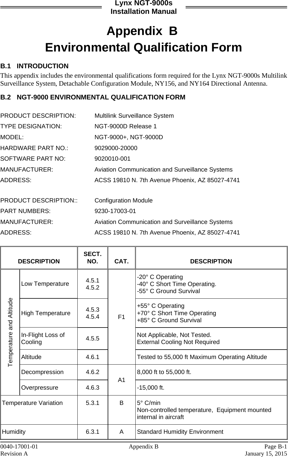
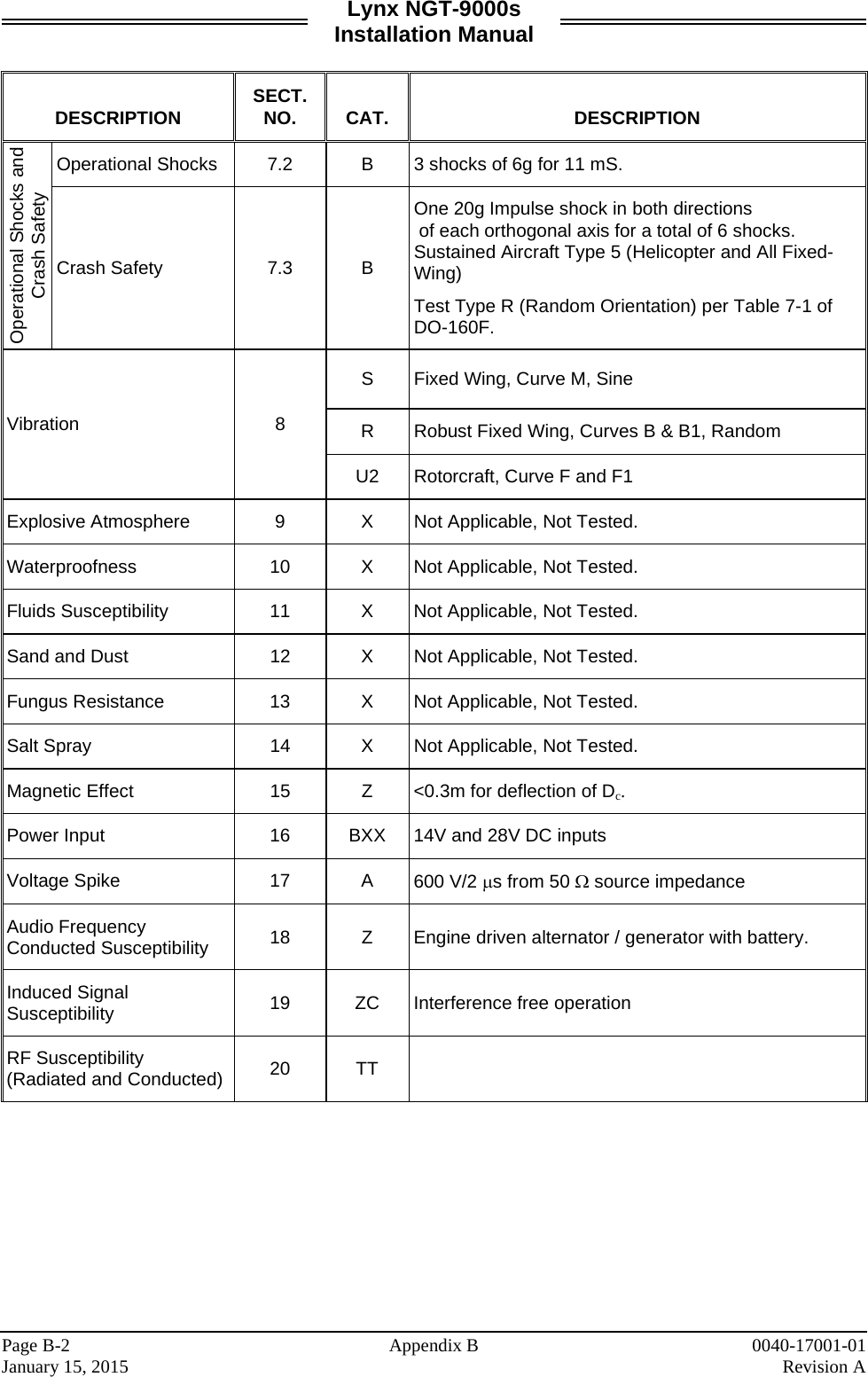
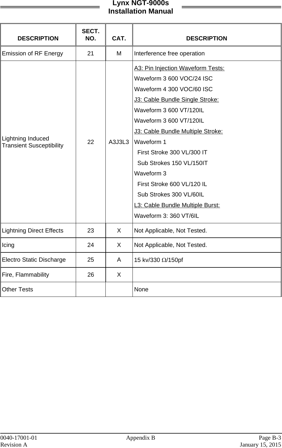
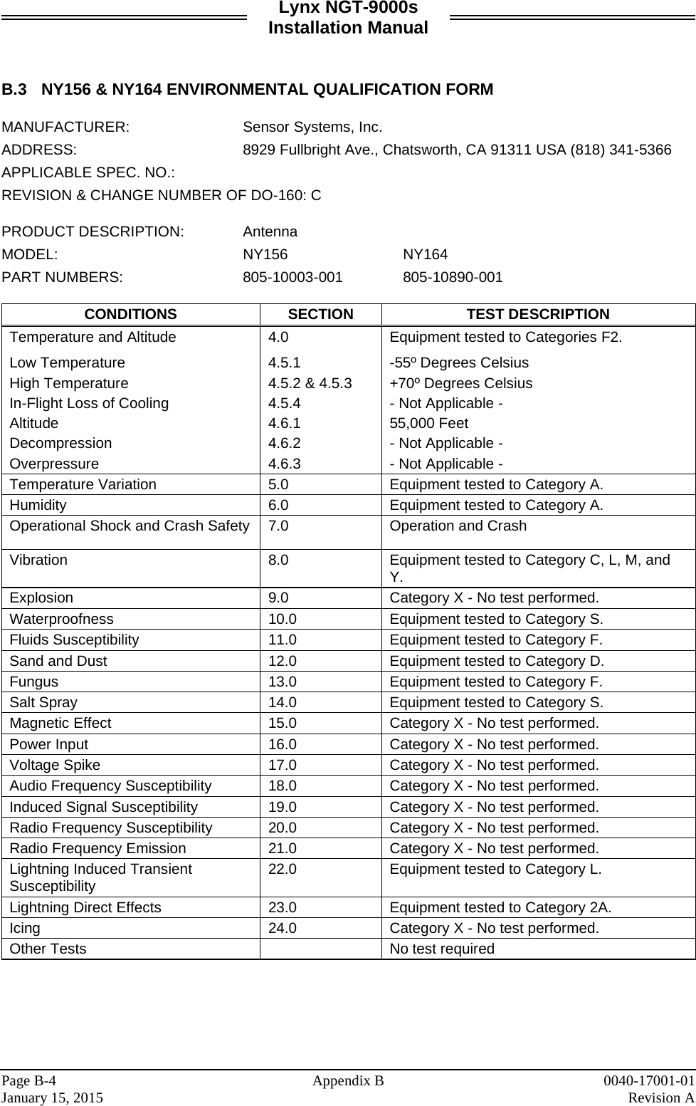
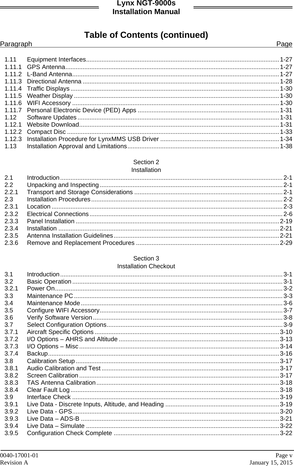
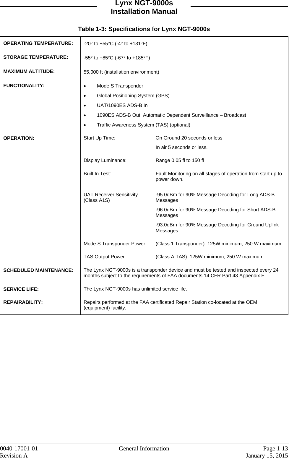
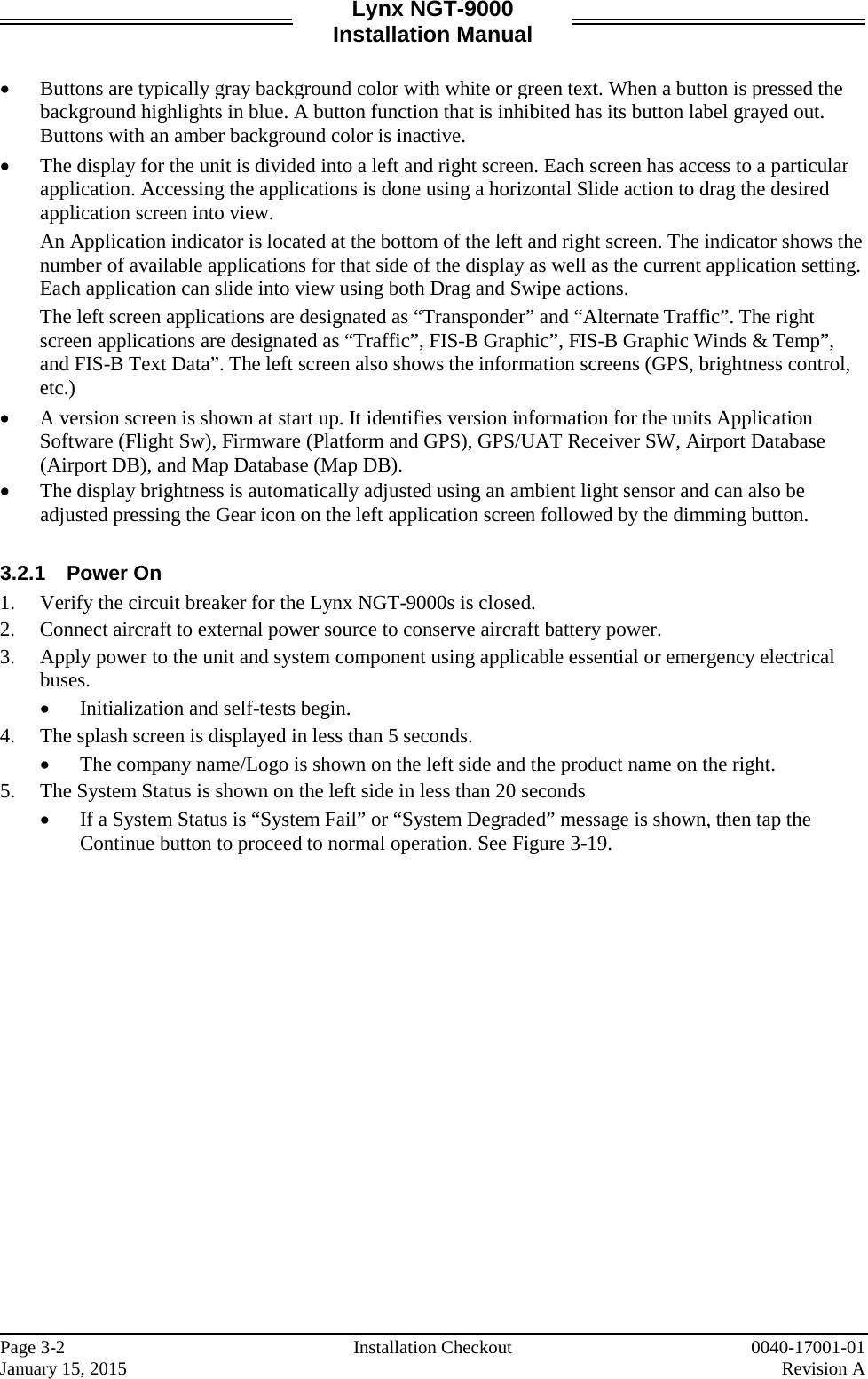
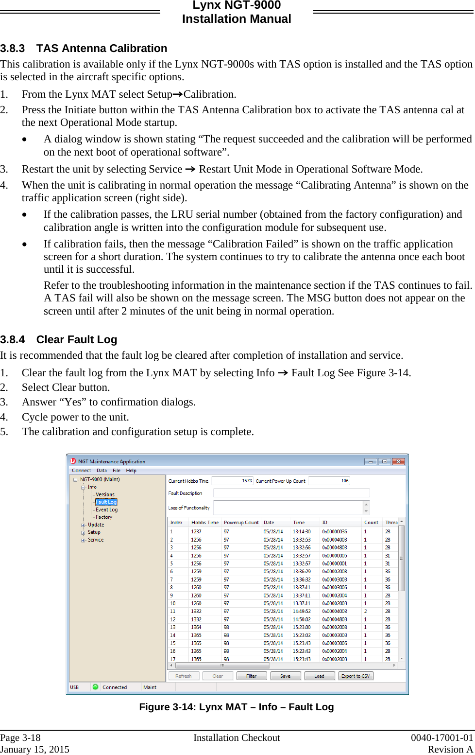
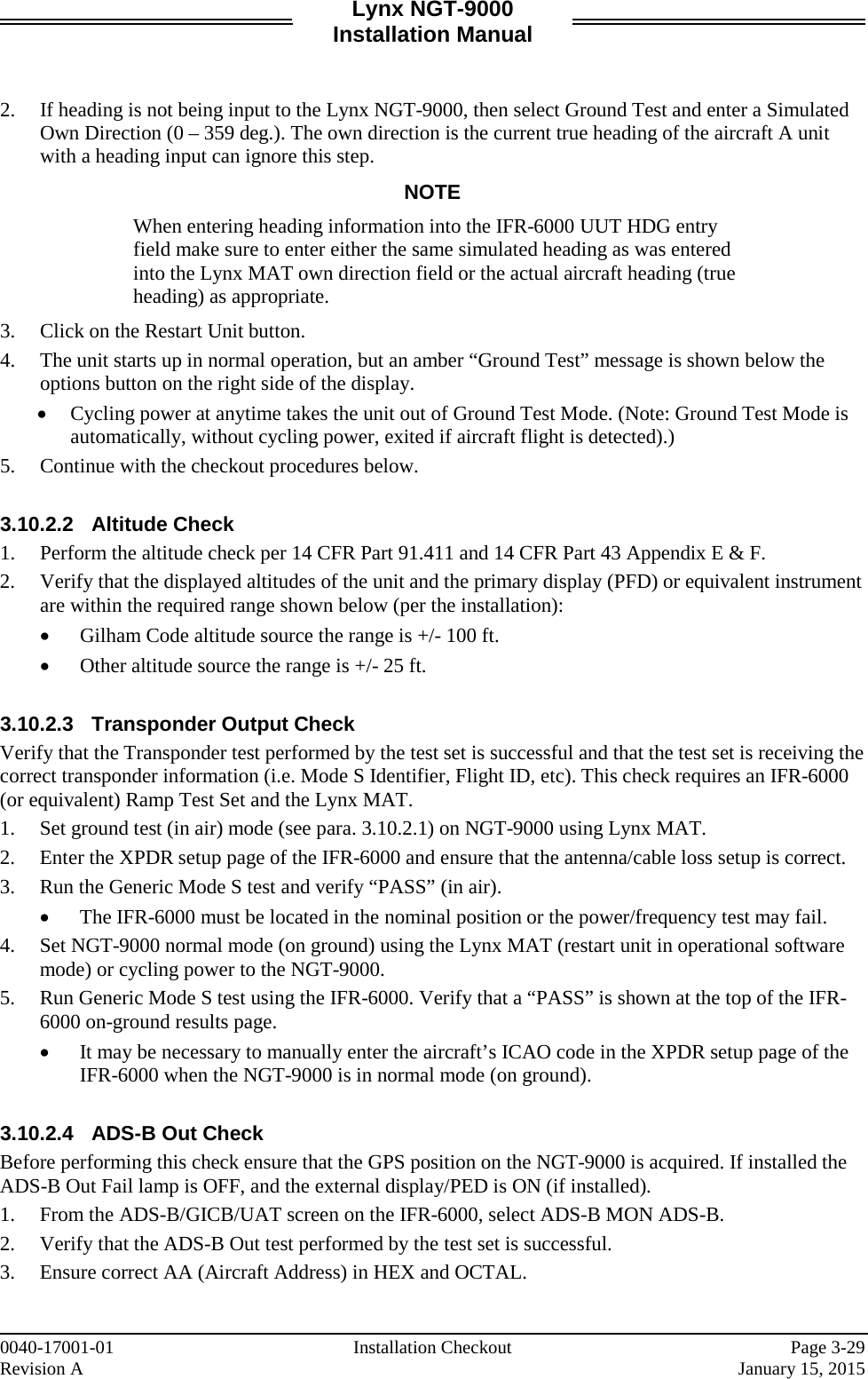
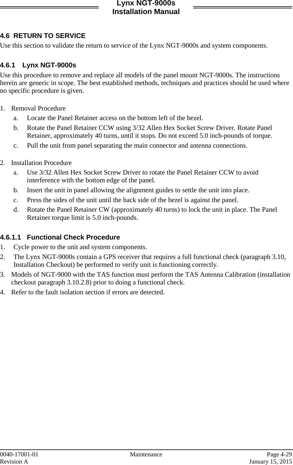
![Lynx NGT-9000s Installation Manual 1.6 SPECIFICATIONS Table 1-3: Specifications for Lynx NGT-9000s PART NUMBERS: 9029000-20000 CERTIFICATION: USA (FAA): TSO-C112d, C113a, C145c, C147, C154c, C157a, C166b, C195a. See paragraph 1.7 for specific TSO information. Listed are current authorizations at time of publication, contact Field Service Engineering for latest certification information ADVISORY CIRCULARS: AC20-21-46, AC20-115B, AC20-152, AC20-165A, AC20-172A RTCA COMPLIANCE: Environmental Category: DO-160G (See Environmental Qualification Form in Appendix B.) Software Category: DO-178B, Design Assurance Level C Hardware Category: DO-254, Design Assurance Level C Other: DO-181E, DO-197A, DO-229D, DO-260B, DO-267A, DO-282B, DO-317A, ARINC 718A-4 and SAE AS8034B. COMPLIANCE: ATC transponder functionality: 14 CFR 91.215, 91.217, 91.413 ADS-B Out functionality: 14 CFR 91.225, and 91.227 The Lynx NGT-9000s has been shown to meet the requirements in TSO-C166b and meets the requirements of 14 CFR 91.227 installed in accordance with these installation instructions. SIZE: Case Width 1.48 inches [12.83 cm] MAX Height: 5.75 inches [7.42 cm] MAX Depth*: 8.99 inches [3.81 cm] MAX Bezel Width 6.25 inches [13.44 cm] MAX Height: 1.8 inches [7.62 cm] MAX * Does not include connectors. Note: Unit Fits into a “MARK width” panel. WEIGHT: Nominal 1.0 Lbs (0.5 kg) Maximum 4.0 Lbs (0.8 kg) CHASSIS GROUND: Bonding impedance between aircraft ground and the Lynx NGT-9000s Chassis must be less than 2.5 milliohms. POWER REQUIREMENTS: +14.0 VDC nominal. 19.0 watts nominal (24.0 watts maximum) +28.0 VDC nominal. 19.0 watts nominal (24.0 watts maximum) ELECTRICAL CONNECTORS: • 78 position d-subminiature connector receptacle (shell size 5) with swaged float plate. Connector insert per MIL-DTL-24308, Appendix A, Figure A-5, Arrangement 2. Connector insert shall accommodate 22D removable crimp contacts (socket) per M39029/57-324, or equivalent. • RF Connectors: 5W5 Coax D-Sub • Mini-B USB: Maintenance Port INTERFACE (S): • ARINC 429 • RS-422 • RS-232 • Discrete Input/Outputs • RF Suppression Bus • I2C serial interface (detachable configuration module interface) Note: Refer to Appendix A for signal names and characteristics Page 1-12 General Information 0040-17001-01 January 15, 2015 Revision A](https://usermanual.wiki/Aviation-Communications-and-Surveillance-Systems/MSS90/User-Guide-2530994-Page-28.png)
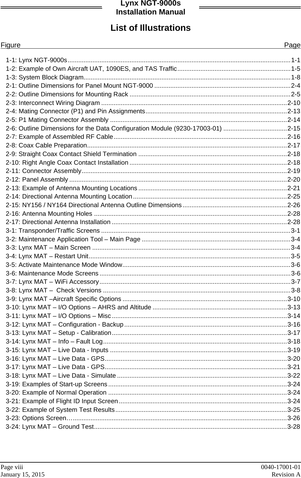
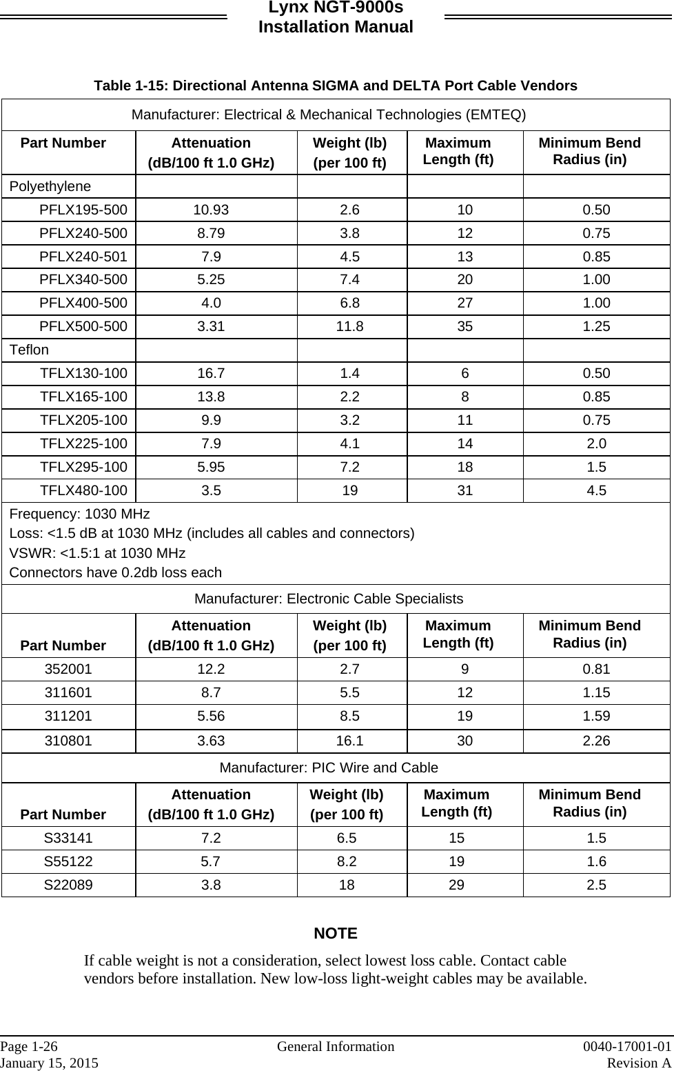
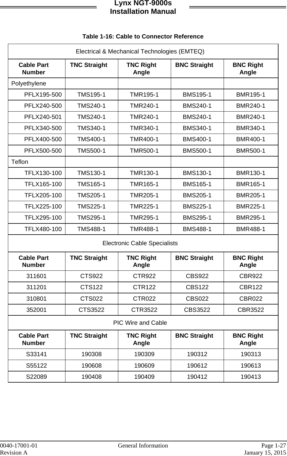
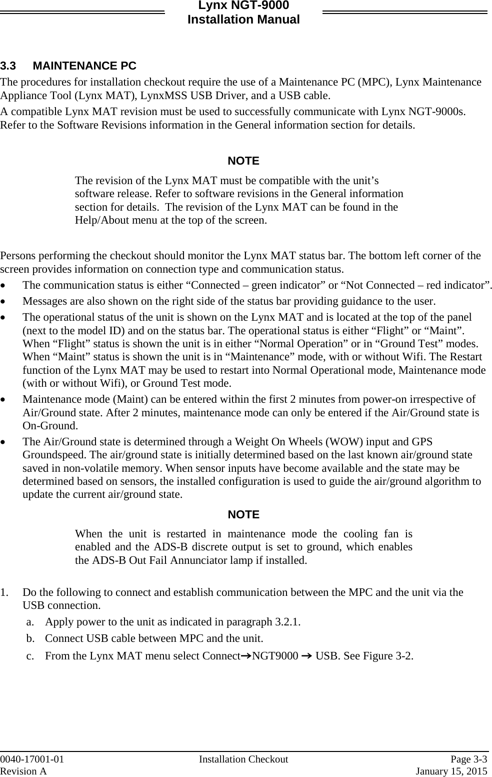
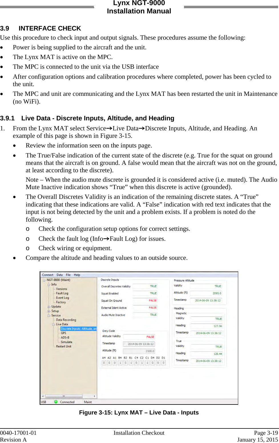
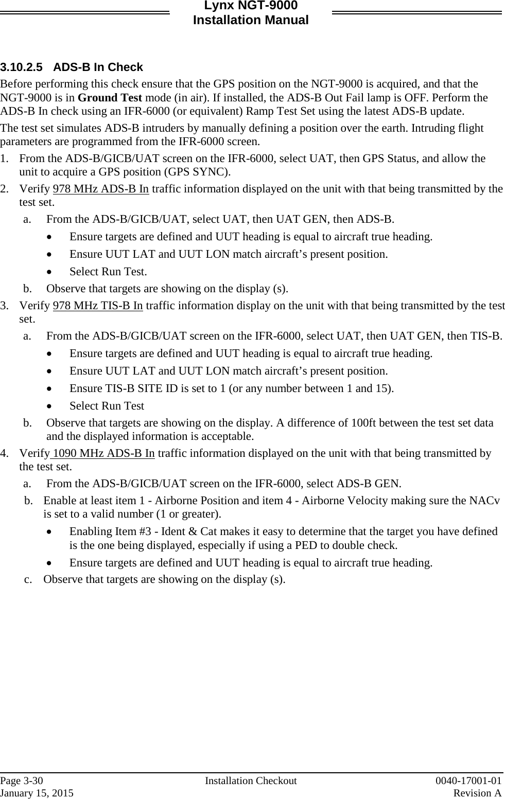
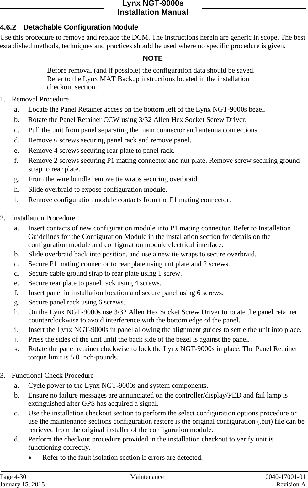
![Lynx NGT-9000s Installation Manual 1.10.2 Antenna Cables For L-Band and GPS antenna cables, Table 1-14 lists examples of the recommended antenna cable vendors and the type of cable to be used for specific lengths of cable. For Directional antenna cables, Table 1-15 identifies U. S. vendors who sell approved cables by the foot. Table 1-16 provides a cable to connector cross-reference. Any cable meeting specifications is acceptable for the installation. Table 1-14: Coaxial Cable Specifications INSERTION LOSS (DB/100FT) [1] CARLISLE IT TYPE [2] MIL-C-17 TYPE [3] RG TYPE 18.5 N/A M17/128-RG400 RG-400 11.1 N/A M17/112-RG304 RG-304 9.2 N/A M17/127-RG393 RG-393 15.2 3C142B N/A N/A 9.2 311601 N/A N/A 7.5 311501 N/A N/A 5.8 311201 N/A N/A 3.8 310801 N/A N/A [1] RG type coaxial cable insertion loss can vary significantly between manufacturers. The insertion loss for RG type cables shown in this column is considered 'worst case'. Refer to the cable manufacturer's specification sheet for actual attenuation (insertion loss) for the cable being used. [2] Supplier information (for reference only): Carlisle IT 5300 W. Franklin Drive Franklin, WI 53132 Tel: 800-327-9473 414-421-5300 Fax: 414-421-5301 www.carlisle.com Alternate cable suppliers: Pic Wire (www.picwire.com) and EMTEQ (www.emteq.com) [3] Supplier information: See current issue of Qualified Products List QPL-17. 0040-17001-01 General Information Page 1-25 Revision A January 15, 2015](https://usermanual.wiki/Aviation-Communications-and-Surveillance-Systems/MSS90/User-Guide-2530994-Page-41.png)
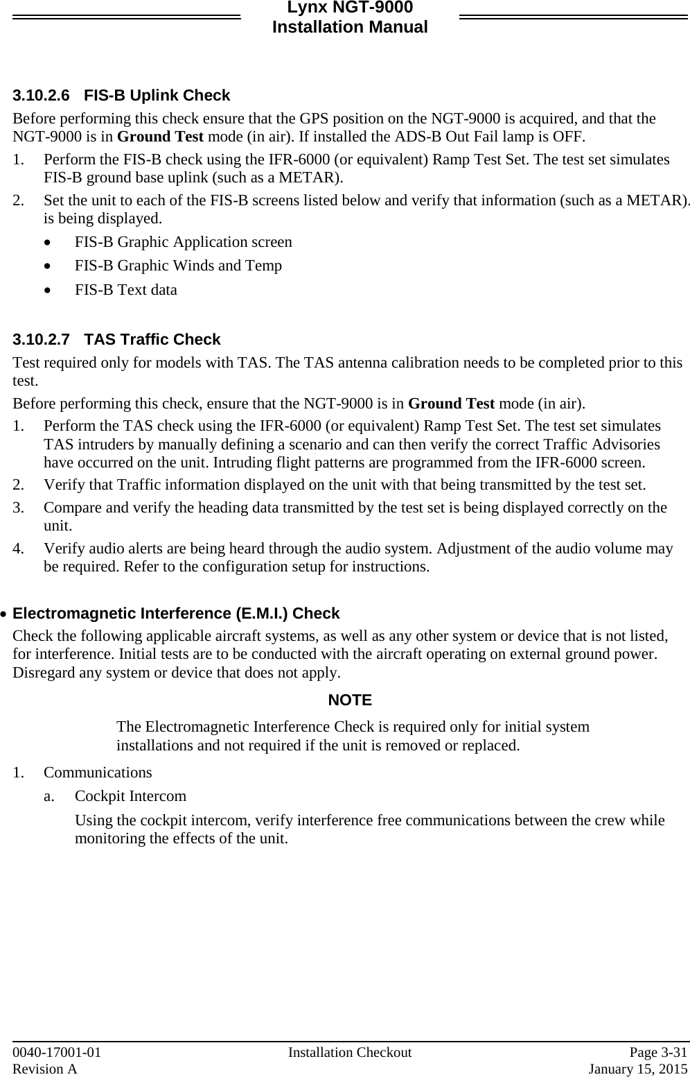

![Lynx NGT-9000s Installation Manual A.4 [J1 CONNECTOR] PIN 1 Signal Name: PWR_14_28VDC_IN Signal Function: + 14/28 VDC Power IN 1 Electrical Characteristics: 30.0 watts maximum average Connection: Aircraft 28V BUS. 22 AWG wire Comments: PIN 2 Signal Name: PWR_14_28VDC_IN Signal Function: + 14/28 VDC Power IN 2 Electrical Characteristics: 30.0 watts maximum average Connection: Aircraft 28V BUS. 22 AWG wire Comments: PIN 3 Signal Name: Ground Signal Function: 14/28 V Power Return 1 Electrical Characteristics: -------- Connection: Aircraft 14 or 28V Return BUS 22 AWG wire Comments: PIN 4 Signal Name: Ground Signal Function: 14/28 V Power Return 2 Electrical Characteristics: -------- Connection: Aircraft 14 or 28V Return BUS 22 AWG wire Comments: PIN 5 Signal Name: ALT_IN_A1 Signal Function: Gilham Altitude Encoder Electrical Characteristics: +30 V input max, < 1 mA sourced per line Frequency: 20 Hz, Source Z: > 10 kΩ per line Max Capacitance: < 20 pF per line Connection: See paragraph A.2.4 24 AWG wire Comments: 0040-17001-01 Appendix A Page A-9 Revision A January 15, 2015](https://usermanual.wiki/Aviation-Communications-and-Surveillance-Systems/MSS90/User-Guide-2530994-Page-161.png)
![Lynx NGT-9000s Installation Manual [J1 connector] (Continued) PIN 6 Signal Name: ALT_IN_A2 Signal Function: Gilham Altitude Encoder Electrical Characteristics: +30 V input max, < 1 mA sourced per line Frequency: 20 Hz, Source Z: > 10 kΩ per line Max Capacitance: < 20 pF per line Connection: See paragraph A.2.4 24 AWG wire Comments: PIN 7 Signal Name: ALT_IN_A4 Signal Function: Gilham Altitude Encoder Electrical Characteristics: +30 V input max, < 1 mA sourced per line Frequency: 20 Hz, Source Z: > 10 kΩ per line Max Capacitance: < 20 pF per line Connection: See paragraph A.2.4 24 AWG wire Comments: PIN 8 Signal Name: ALT_IN_B1 Signal Function: Gilham Altitude Encoder Electrical Characteristics: +30 V input max, < 1 mA sourced per line Frequency: 20 Hz, Source Z: > 10 kΩ per line Max Capacitance: < 20 pF per line Connection: See paragraph A.2.4 24 AWG wire Comments: PIN 9 Signal Name: ALT_IN_B2 Signal Function: Gilham Altitude Encoder Electrical Characteristics: +30 V input max, < 1 mA sourced per line Frequency: 20 Hz, Source Z: > 10 kΩ per line Max Capacitance: < 20 pF per line Connection: See paragraph A.2.4 24 AWG wire Comments: Page A-10 Appendix A 0040-17001-01 January 15, 2015 Revision A](https://usermanual.wiki/Aviation-Communications-and-Surveillance-Systems/MSS90/User-Guide-2530994-Page-162.png)
![Lynx NGT-9000s Installation Manual [J1 connector] (Continued) PIN 10 Signal Name: ALT_IN_B4 Signal Function: Gilham Altitude Encoder Electrical Characteristics: +30 V input max, < 1 mA sourced per line Frequency: 20 Hz, Source Z: > 10 kΩ per line Max Capacitance: < 20 pF per line Connection: See paragraph A.2.4 24 AWG wire Comments: PIN 11 Signal Name: ALT_IN_C1 Signal Function: Gilham Altitude Encoder Electrical Characteristics: +30 V input max, < 1 mA sourced per line Frequency: 20 Hz, Source Z: > 10 kΩ per line Max Capacitance: < 20 pF per line Connection: See paragraph A.2.4 24 AWG wire Comments: PIN 12 Signal Name: ALT_IN_C2 Signal Function: Gilham Altitude Encoder Electrical Characteristics: +30 V input max, < 1 mA sourced per line Frequency: 20 Hz, Source Z: > 10 kΩ per line Max Capacitance: < 20 pF per line Connection: See paragraph A.2.4 24 AWG wire Comments: PIN 13 Signal Name: ALT_IN_C4 Signal Function: Gilham Altitude Encoder Electrical Characteristics: +30 V input max, < 1 mA sourced per line Frequency: 20 Hz, Source Z: > 10 kΩ per line Max Capacitance: < 20 pF per line Connection: See paragraph A.2.4 24 AWG wire Comments: 0040-17001-01 Appendix A Page A-11 Revision A January 15, 2015](https://usermanual.wiki/Aviation-Communications-and-Surveillance-Systems/MSS90/User-Guide-2530994-Page-163.png)
![Lynx NGT-9000s Installation Manual [J1 connector] (Continued) PIN 14 Signal Name: ALT_IN_D2 Signal Function: Gilham Altitude Encoder Electrical Characteristics: +30 V input max, < 1 mA sourced per line Frequency: 20 Hz, Source Z: > 10 kΩ per line Max Capacitance: < 20 pF per line Connection: Not Connected Comments: This input used for high altitude aircraft. PIN 15 Signal Name: ALT_IN_D4 Signal Function: Gilham Altitude Encoder Electrical Characteristics: +30 V input max, < 1 mA sourced per line Frequency: 20 Hz, Source Z: > 10 kΩ per line Max Capacitance: < 20 pF per line Connection: See paragraph A.2.4 24 AWG wire Comments: PIN 16 Signal Name: GROUND Signal Function: Signal Ground Electrical Characteristics: --- Connection: Ground Comments: PIN 17 Signal Name: CM SDA Signal Function: SDA Serial Data Electrical Characteristics: See paragraph A.2.11 Connection: Detachable Configuration Module – Yellow wire Comments: PIN 18 Signal Name: CM SCL Signal Function: SCL Serial Clock Electrical Characteristics: See paragraph A.2.11 Connection: Detachable Configuration Module – green wire Comments: Page A-12 Appendix A 0040-17001-01 January 15, 2015 Revision A](https://usermanual.wiki/Aviation-Communications-and-Surveillance-Systems/MSS90/User-Guide-2530994-Page-164.png)
![Lynx NGT-9000s Installation Manual [J1 connector] (Continued) PIN 19 Signal Name: CM 3.3V Signal Function: SPWR Serial Power (3.3 Vdc Power), 50ma max Electrical Characteristics: See paragraph A.2.11 Connection: Detachable Configuration Module – red wire Comments: PIN 20 Signal Name: CM GND Signal Function: SGND Serial Ground Electrical Characteristics: See paragraph A.2.11 Connection: Detachable Configuration Module – Black wire Comments: PIN 21 Signal Name: DISC_OUT1 (Discrete Output No. 1) Signal Function: Reserved (TAWS Caution) Electrical Characteristics: GND/Open (GND active) Ground State < 3.0Vdc when sinking 250mA. Open State has an impedance of >100K ohms to ground for voltages applied to the output of 0.0 to 36.0Vdc. Connection: No Connection Comments: See paragraph A.2.10. PIN 22 Signal Name: DISC_OUT2 (Discrete Output No. 2) Signal Function: Reserved (TAWS Warning) Electrical Characteristics: GND/Open (GND active) Ground State < 3.0Vdc when sinking 250mA. Open State has an impedance of >100K ohms to ground for voltages applied to the output of 0.0 to 36.0Vdc. Connection: No Connection Comments: See paragraph A.2.10. PIN 23 Signal Name: DISC_OUT3 (Discrete Output No. 3) Signal Function: TAS Alert. Electrical Characteristics: GND/Open (GND active) Ground State < 3.0Vdc when sinking 250mA. Open State has an impedance of >100K ohms to ground for voltages applied to the output of 0.0 to 36.0Vdc. Connection: Indicator Lamp 24 AWG wire Comments: See paragraph A.2.10. 0040-17001-01 Appendix A Page A-13 Revision A January 15, 2015](https://usermanual.wiki/Aviation-Communications-and-Surveillance-Systems/MSS90/User-Guide-2530994-Page-165.png)
![Lynx NGT-9000s Installation Manual [J1 connector] (Continued) PIN 24 Signal Name: DISC_OUT4 (Discrete Output No. 4) Signal Function: TIS-B Not in coverage Electrical Characteristics: GND/Open (GND active) Ground State < 3.0Vdc when sinking 250mA. Open State has an impedance of >100K ohms to ground for voltages applied to the output of 0.0 to 36.0Vdc. Connection: Indicator Lamp 24 AWG wire Comments: See paragraph A.2.10. PIN 25 Signal Name: DISC_OUT5 (Discrete Output No. 5) Signal Function: Reserved (Audio Mute Command) Electrical Characteristics: GND/Open (GND active) Ground State < 3.0Vdc when sinking 250mA. Open State has an impedance of >100K ohms to ground for voltages applied to the output of 0.0 to 36.0Vdc. Connection: No Connection Comments: See paragraph A.2.10. PIN 26 Signal Name: DISC_OUT6 (Discrete Output No. 6) Signal Function: ADS-B Fail Indicator Electrical Characteristics: GND/Open (GND active) Ground State < 3.0Vdc when sinking 250mA. Open State has an impedance of >100K ohms to ground for voltages applied to the output of 0.0 to 36.0Vdc. Connection: Indicator Lamp 24 AWG wire Comments: See paragraph A.2.10. PIN 27 Signal Name: DISC_IN1 (Discrete Input No. 1) Signal Function: IDENT Electrical Characteristics: GND/Open (GND active) Ground State ≤ 3.5Vdc, Open State ≥ 18Vdc Connection: Momentary Switch 24 AWG wire Comments: See paragraph A.2.9. Page A-14 Appendix A 0040-17001-01 January 15, 2015 Revision A](https://usermanual.wiki/Aviation-Communications-and-Surveillance-Systems/MSS90/User-Guide-2530994-Page-166.png)
![Lynx NGT-9000s Installation Manual [J1 connector] (Continued) PIN 28 Signal Name: DISC_IN2 (Discrete Input No. 2) Signal Function: Audio Mute Electrical Characteristics: GND/Open (GND active) Ground State ≤ 3.5Vdc, Open State ≥ 18Vdc Connection: 24 AWG wire Comments: When active all traffic alerts are suppressed. Typically connected to TAWS or other aircraft warning device with a higher audio priority. See paragraph A.2.9. PIN 29 Signal Name: DISC_IN3 (Discrete Input No. 3) Signal Function: WOW (Squat / Air Speed Monitor input) Electrical Characteristics: DCM selectable for GND active or Open active. Ground State ≤ 3.5Vdc, Open State ≥ 18Vdc Connection: On/Off Switch 24 AWG wire Comments: See paragraph A.2.9. PIN 30 Signal Name: DISC_IN4 (Discrete Input No. 4) Signal Function: Reserved (TSAA Inhibit) Electrical Characteristics: GND/Open (GND active) Ground State ≤ 3.5Vdc, Open State ≥ 18Vdc Connection: No Connection Comments: See paragraph A.2.9. PIN 31 Signal Name: DISC_IN5 (Discrete Input No. 5) Signal Function: Spare Electrical Characteristics: GND/Open (GND active) Ground State ≤ 3.5Vdc, Open State ≥ 18Vdc Connection: No Connection Comments: See paragraph A.2.9. PIN 32 Signal Name: DISC_IN6 (Discrete Input No. 6) Signal Function: Spare Electrical Characteristics: GND/Open (GND active) Ground State ≤ 3.5Vdc, Open State ≥ 18Vdc Connection: No Connection Comments: See paragraph A.2.9. 0040-17001-01 Appendix A Page A-15 Revision A January 15, 2015](https://usermanual.wiki/Aviation-Communications-and-Surveillance-Systems/MSS90/User-Guide-2530994-Page-167.png)
![Lynx NGT-9000s Installation Manual [J1 connector] (Continued) PIN 33 Signal Name: SUPPR_BUS Signal Function: RF Suppression Output Electrical Characteristics: See paragraph A.2.2 Connection: Aircraft Suppression Bus 24 AWG twisted shielded wire Comments: PIN 34 Signal Name: Spare Signal Function: Spare pin Electrical Characteristics: --- Connection: No Connection Comments: PIN 35 Signal Name: Spare Signal Function: Spare pin Electrical Characteristics: --- Connection: No Connection Comments: PIN 36 Signal Name: Spare Signal Function: Spare pin Electrical Characteristics: --- Connection: No Connection Comments: PIN 37 Signal Name: Spare Signal Function: Spare pin Electrical Characteristics: --- Connection: No Connection Comments: Page A-16 Appendix A 0040-17001-01 January 15, 2015 Revision A](https://usermanual.wiki/Aviation-Communications-and-Surveillance-Systems/MSS90/User-Guide-2530994-Page-168.png)
![Lynx NGT-9000s Installation Manual [J1 connector] (Continued) PIN 38 Signal Name: AUDIO OUT Signal Function: Audio Out 600 Ohm H Electrical Characteristics: 40 milli Watts (RMS) at 1000 Hz into a 600 Ohm audio distribution system. Connection: Audio Panel 24 AWG twisted shielded pair wire Comments: See paragraph A.2.3 PIN 39 Signal Name: GROUND Signal Function: Audio Out 600 Ohm L Electrical Characteristics: Ground Connection: Audio Panel 24 AWG twisted shielded pair wire Comments: See paragraph A.2.3 PIN 40 Signal Name: RX1_429A (ARINC 429_1_IN A) Signal Function: Pressure Altitude Input ARINC 429 Electrical Characteristics: Configuration Option: Low Speed ARINC 429 (12.0 to 14.5 kbps) High Speed ARINC 429 (100 kbps) Connection: 24 AWG twisted shielded pair wire Comments: See paragraph A.2.7. PIN 41 Signal Name: RX1_429B (ARINC 429_1_IN B) Signal Function: Pressure Altitude Input ARINC 429 Electrical Characteristics: Configuration Option: Low Speed ARINC 429 (12.0 to 14.5 kbps) High Speed ARINC 429 (100 kbps) Connection: 24 AWG twisted shielded pair wire Comments: See paragraph A.2.7. PIN 42 Signal Name: RX2_429A (ARINC 429_2_IN A) Signal Function: AHRS Input ARINC 429 Electrical Characteristics: Configuration Option: Low Speed ARINC 429 (12.0 to 14.5 kbps) High Speed ARINC 429 (100 kbps) Combo Bus Connection: 24 AWG twisted shielded pair wire Comments: See paragraph A.2.7. 0040-17001-01 Appendix A Page A-17 Revision A January 15, 2015](https://usermanual.wiki/Aviation-Communications-and-Surveillance-Systems/MSS90/User-Guide-2530994-Page-169.png)
![Lynx NGT-9000s Installation Manual [J1 connector] (Continued) PIN 43 Signal Name: RX2_429B (ARINC 429_2_IN B) Signal Function: AHRS Input ARINC 429 Electrical Characteristics: Configuration Option: Low Speed ARINC 429 (12.0 to 14.5 kbps) High Speed ARINC 429 (100 kbps) Combo Bus Connection: 24 AWG twisted shielded pair wire Comments: See paragraph A.2.7. PIN 44 Signal Name: RX3_429A (ARINC 429_3_IN A) Signal Function: Reserved Electrical Characteristics: Configuration Option: Low Speed ARINC 429 (12.0 to 14.5 kbps) High Speed ARINC 429 (100 kbps) Connection: 24 AWG twisted shielded pair wire Comments: See paragraph A.2.7. PIN 45 Signal Name: RX3_429B (ARINC 429_3_IN B) Signal Function: Reserved Electrical Characteristics: Configuration Option: Low Speed ARINC 429 (12.0 to 14.5 kbps) High Speed ARINC 429 (100 kbps) Connection: 24 AWG twisted shielded pair wire Comments: See paragraph A.2.7. PIN 46 Signal Name: RX4_429A (ARINC 429_4_IN A) Signal Function: Configurable – Combo Bus 429 #2 Electrical Characteristics: High Speed ARINC 429 (100 kbps) Connection: 24 AWG twisted shielded pair wire Comments: See paragraph A.2.7. PIN 47 Signal Name: RX4_429B (ARINC 429_4_IN B) Signal Function: Configurable – Combo Bus 429 #2 Electrical Characteristics: High Speed ARINC 429 (100 kbps) Connection: 24 AWG twisted shielded pair wire Comments: See paragraph A.2.7. Page A-18 Appendix A 0040-17001-01 January 15, 2015 Revision A](https://usermanual.wiki/Aviation-Communications-and-Surveillance-Systems/MSS90/User-Guide-2530994-Page-170.png)
![Lynx NGT-9000s Installation Manual [J1 connector] (Continued) PIN 48 Signal Name: TX_429A (ARINC 429_IN A) Signal Function: ARINC 429 Output for CDTI display Electrical Characteristics: High Speed ARINC 429 (100 kbps) L-3 Sky-497 STIF format Connection: 24 AWG twisted shielded pair wire Comments: See paragraph A.2.8 PIN 49 Signal Name: TX_429B (ARINC 429_IN B) Signal Function: ARINC 429 Output for CDTI display Electrical Characteristics: High Speed ARINC 429 (100 kbps) L-3 Sky-497 STIF format Connection: 24 AWG twisted shielded pair wire Comments: See paragraph A.2.8 PIN 50 Signal Name: RS422_RX2A Signal Function: RS-422 FIS-B Input Electrical Characteristics: Data bits 8, Parity none, Stop bit 1, Start bit 1, Data format is ASCII, Flow control is none. Baud Rate: (configuration option) 38400, 57600, or 115200. Depending on the equipment manufacturer Connection: Optional. 24 AWG twisted shielded pair wire Comments: See paragraph A.2.6 PIN 51 Signal Name: RS422_RX2B Signal Function: RS-422 FIS-B Input Electrical Characteristics: Data bits 8, Parity none, Stop bit 1, Start bit 1, Data format is ASCII, Flow control is none. Baud Rate: (configuration option) 38400, 57600, or 115200. Depending on the equipment manufacturer Connection: Optional. 24 AWG twisted shielded pair wire Comments: See paragraph A.2.6 PIN 52 Signal Name: RS422_TX2A Signal Function: RS-422 FIS-B Output Electrical Characteristics: Data bits 8, Parity none, Stop bit 1, Start bit 1, Data format is ASCII, Flow control is none. Baud Rate: (configuration option) 38400, 57600, or 115200. Depending on the equipment manufacturer Connection: Optional. 24 AWG twisted shielded pair wire Comments: See paragraph A.2.6 0040-17001-01 Appendix A Page A-19 Revision A January 15, 2015](https://usermanual.wiki/Aviation-Communications-and-Surveillance-Systems/MSS90/User-Guide-2530994-Page-171.png)
![Lynx NGT-9000s Installation Manual [J1 connector] (Continued) PIN 53 Signal Name: RS422_TX2B Signal Function: RS-422 FIS-B Output Electrical Characteristics: Data bits 8, Parity none, Stop bit 1, Start bit 1, Data format is ASCII, Flow control is none. Baud Rate: (configuration option) 38400, 57600, or 115200. Depending on the equipment manufacturer Connection: Optional. 24 AWG twisted shielded pair wire Comments: See paragraph A.2.6 PIN 54 Signal Name: Spare Signal Function: Spare pin Electrical Characteristics: --- Connection: No Connection Comments: PIN 55 Signal Name: Spare Signal Function: Spare pin Electrical Characteristics: --- Connection: No Connection Comments: PIN 56 Signal Name: Spare Signal Function: Spare pin Electrical Characteristics: --- Connection: No Connection Comments: PIN 57 Signal Name: Spare Signal Function: Spare pin Electrical Characteristics: --- Connection: No Connection Comments: Page A-20 Appendix A 0040-17001-01 January 15, 2015 Revision A](https://usermanual.wiki/Aviation-Communications-and-Surveillance-Systems/MSS90/User-Guide-2530994-Page-172.png)
![Lynx NGT-9000s Installation Manual [J1 connector] (Continued) PIN 58 Signal Name: Spare Signal Function: Spare pin Electrical Characteristics: --- Connection: No Connection Comments: PIN 59 Signal Name: Spare Signal Function: Spare pin Electrical Characteristics: --- Connection: No Connection Comments: PIN 60 Signal Name: RS232_RX3 Signal Function: Altitude Encoder RS-232 RX (Encoder Input) Electrical Characteristics: Data bits (configuration option) 7 or 8, Parity none, Stop bit 1, Start bit 1, Data format is ASCII, Flow control is none. Baud Rate: (configuration option) 1200, 2400, 4800, 9600, 12000, 19200, 28800, 38400, 57600, or 115200 bps. Depending on the equipment manufacturer and selected in the DCM. Connection: Optional. 24 AWG twisted shielded pair wire Comments: See paragraph A.2.5.2 PIN 61 Signal Name: RS232_RX1 Signal Function: RS-232 Control Panel Interface Electrical Characteristics: Data bits 8, Parity none, Stop bit 1, Start bit 1, Data format is ASCII, Flow control is none. Baud Rate: (configuration option) 1200, 2400, or 9600 bps. Depending on the equipment manufacturer Connection: Optional. 24 AWG twisted shielded pair wire Comments: See paragraph A.2.5.2 PIN 62 Signal Name: RS232_TX1 Signal Function: RS-232 Control Panel Interface Electrical Characteristics: Data bits 8, Parity none, Stop bit 1, Start bit 1, Data format is ASCII, Flow control is none. Baud Rate: (configuration option) 1200, 2400, or 9600 bps. Depending on the equipment manufacturer Connection: Optional. 24 AWG twisted shielded pair wire Comments: See paragraph A.2.5.2 0040-17001-01 Appendix A Page A-21 Revision A January 15, 2015](https://usermanual.wiki/Aviation-Communications-and-Surveillance-Systems/MSS90/User-Guide-2530994-Page-173.png)
![Lynx NGT-9000s Installation Manual [J1 connector] (Continued) PIN 63 Signal Name: RS232_RX2 Signal Function: RS-232 PED/Wi-Fi Device Electrical Characteristics: Data bits 8, Parity none, Stop bit 1, Start bit 1, Data format is ASCII, Flow control is none. Baud Rate: 115200 bps. Connection: Optional. 24 AWG twisted shielded pair wire Comments: See paragraph A.2.5.1 PIN 64 Signal Name: RS232_TX2 Signal Function: RS-232 PED/Wi-Fi Device Electrical Characteristics: Data bits 8, Parity none, Stop bit 1, Start bit 1, Data format is ASCII, Flow control is none. Baud Rate: 115200 bps. Connection: Optional. 24 AWG twisted shielded pair wire Comments: See paragraph A.2.5.1 PIN 65 Signal Name: RESERVED Signal Function: RS-232 (Factory Only) Electrical Characteristics: --- Connection: No Connection Comments: PIN 66 Signal Name: RESERVED Signal Function: RS-232 (Factory Only) Electrical Characteristics: --- Connection: No Connection Comments: PIN 67 Signal Name: RESERVED Signal Function: RS-232 (Factory Only) Electrical Characteristics: --- Connection: No Connection Comments: Page A-22 Appendix A 0040-17001-01 January 15, 2015 Revision A](https://usermanual.wiki/Aviation-Communications-and-Surveillance-Systems/MSS90/User-Guide-2530994-Page-174.png)
![Lynx NGT-9000s Installation Manual [J1 connector] (Continued) PIN 68 Signal Name: RESERVED Signal Function: RS-232 (Factory Only) Electrical Characteristics: --- Connection: No Connection Comments: PIN 69 Signal Name: Spare Signal Function: Spare pin Electrical Characteristics: --- Connection: No Connection Comments: PIN 70 Signal Name: Spare Signal Function: Spare pin Electrical Characteristics: --- Connection: No Connection Comments: PIN 71 Signal Name: Spare Signal Function: Spare pin Electrical Characteristics: --- Connection: No Connection Comments: PIN 72 Signal Name: Spare Signal Function: Spare pin Electrical Characteristics: --- Connection: No Connection Comments: PIN 73 Signal Name: Spare Signal Function: Spare pin Electrical Characteristics: --- Connection: No Connection Comments: 0040-17001-01 Appendix A Page A-23 Revision A January 15, 2015](https://usermanual.wiki/Aviation-Communications-and-Surveillance-Systems/MSS90/User-Guide-2530994-Page-175.png)
![Lynx NGT-9000s Installation Manual [J1 connector] (Continued) PIN 74 Signal Name: Spare Signal Function: Spare pin Electrical Characteristics: --- Connection: No Connection Comments: PIN 75 Signal Name: Spare Signal Function: Spare pin Electrical Characteristics: --- Connection: No Connection Comments: PIN 76 Signal Name: RESEARVED Signal Function: TCAS Pretrigger test output Electrical Characteristics: --- Connection: No Connection Comments: FACTORY ONLY PIN 77 Signal Name: RESEARVED Signal Function: XPDR Pretrigger test output Electrical Characteristics: --- Connection: No Connection Comments: FACTORY ONLY PIN 78 Signal Name: RESEARVED Signal Function: Antenna Top/Bottom test output Electrical Characteristics: --- Connection: No Connection Comments: FACTORY ONLY Page A-24 Appendix A 0040-17001-01 January 15, 2015 Revision A](https://usermanual.wiki/Aviation-Communications-and-Surveillance-Systems/MSS90/User-Guide-2530994-Page-176.png)