Aviation Communications and Surveillance Systems MSS90 Multi Link Transponder User Manual Installation Manual
Aviation Communications and Surveillance Systems (ACSS), LLC. Multi Link Transponder Installation Manual
Installation Manual

Lynx ® NGT-9000
MultiLink Surveillance System
Part Number: 9029000-( )
Installation Manual
This manual contains installation instructions and
recommended flightline maintenance information
for the Lynx NGT-9000 MultLink Surveillance
System, Configuration Module, and Directional
Antenna. Guidelines for external equipment
necessary for installation are included. This
information is supplemented and kept current by
revisions, service letters and service bulletins.
0040-17001-01 (Revision A)
January 15, 2015

Foreword
This manual provides information intended for use by persons who, in accordance with current regulatory
requirements, are qualified to install this equipment. Installation requirements may vary, depending on the
particularities of each aircraft, and this manual is intended as a guideline for that purpose. This manual
assumes familiarity with the setup and operation of the aircraft systems that interface with the NGT-9000.
If further information is required, please contact:
L-3 Avionics Systems
Attn: Field Service Engineering
5353 52nd Street, S.E.
Grand Rapids, MI USA 49512-9704
Telephone: (800) 453-0288 or (616) 949-6600
Fax: (616) 977-6898
Email: fieldservice.avionics@L-3com.com
Web: http:///www.L-3avionics.com
This manual is distributed with permission by:
L-3 Avionics Systems
5353 52nd Street, S.E.
Grand Rapids, MI USA 49512-9704
Telephone: (800) 453-0288 or (616) 949-6600
Fax: (616) 977-6898
Email: avionics.techpubs@L-3com.com
We welcome your comments concerning this manual. Although every effort has been made to keep it free
of errors, some may occur. When reporting a specific problem, please describe it briefly and include the
manual part number, the paragraph/figure/table number, and the page number. Send your comments to the
address or email above:
WARNING
INFORMATION SUBJECT TO EXPORT CONTROL LAWS
This technical data is controlled under the Export Administration
Regulations (EAR) and may not be exported without proper authorization
by the U.S. Department of Commerce.
Copyright 2015
ACSS
Trademarks
Lynx® is a trademark of L-3 Avionics Systems
Patent Pending
Page A 0040-17001-01
January 15, 2015 Revision A

Lynx NGT-9000s
Installation Manual
About This Manual
SECTION 1 – GENERAL INFORMATION
This section provides the following information: unit configurations, unit functionality, items
required but not supplied with the unit, equipment specifications, installation approval/limitations
and TSO approvals.
SECTION 2 - INSTALLATION
This section contains instructions to locate, assemble and install the Lynx NGT-9000s MultLink
Surveillance System as well as information for unpacking equipment, and inspection procedure for
in-shipment damage.
SECTION 3 – INSTALLATION CHECKOUT
This section contains instructions for post installation setup, post installation and return to service
checkout.
SECTION 4 – MAINTENANCE
This section contains general flightline maintenance procedures. It includes periodic maintenance,
troubleshooting and instructions for the return of defective components.
APPENDIX A – SIGNAL AND CABLE CHARACTERISTICS
This appendix defines the electrical characteristics of all input and output signals.
APPENDIX B – ENVIRONMENTAL QUALIFICATION FORM
This appendix provides the environmental qualification test data.
APPENDIX C – CONFIGURATION AND CHECKOUT LOG
This appendix provides the installer a way to record configuration options.
References
PUBLICATION DESCRIPTION
0040-17000-01 Pilot’s Guide for the NGT-9000
0040-17001-01 Page i
Revision A January 15, 2015

Lynx NGT-9000s
Installation Manual
List of Effective Pages
Dates of original and changed pages are: Revision A .............................. January 15, 2015
Total number of pages in this publication consists of the following:
Title page
Page A
i thru xvi
1-1 thru 1-40
2-1 thru 2-30
3-1 thru 3-34
4-1 thru 4-32
A-1 thru A-24
B-1 thru B-4
C-1 thru C-2
Disclaimer
This Installation Manual contains information that is considered relevant only at the time of distribution
with the Avionics Systems product for which it is shipped. Information in this manual is subject to change
without notice and will not be updated after distribution.
Avionics Systems does provide a listing of all publications and directives with their current revision and
change levels to insure up-to-date information. See www.as.l-3com.com, Customer Care Section,
Technical Publications Page for the Publications Index to get an up-to-date listing of all Avionics Systems
technical publications and directives. Contact Avionics Systems Customer Service [1-800-453-0288] to
determine availability of technical publications and directives.
Revision A Highlights
Original release.
Page ii 0040-17001-01
January 15, 2015 Revision A

Lynx NGT-9000s
Installation Manual
This page intentionally left blank.
0040-17001-01 Page iii
Revision A January 15, 2015

Lynx NGT-9000s
Installation Manual
Table of Contents
Paragraph Page
Foreword ....................................................................................................................................................... A
About This Manual ......................................................................................................................................... i
References ..................................................................................................................................................... i
List of Effective Pages .................................................................................................................................... ii
Revision A Highlights ..................................................................................................................................... ii
Table of Contents .......................................................................................................................................... iv
List of Illustrations ....................................................................................................................................... viii
List of Tables ................................................................................................................................................. x
Abbreviations, Acronyms, and Symbols ....................................................................................................... xi
Section 1
General Information
1.1 Introduction ................................................................................................................................. 1-1
1.2 Functional Description ................................................................................................................ 1-2
1.2.1 GPS Functional Overview .......................................................................................................... 1-2
1.2.2 ADS-B System Overview............................................................................................................ 1-3
1.2.3 ADS-R System Overview ........................................................................................................... 1-3
1.2.4 TIS-B System Overview ............................................................................................................. 1-3
1.2.5 FIS-B System Overview ............................................................................................................. 1-4
1.2.6 Traffic Awareness System (option) Overview ............................................................................ 1-4
1.2.7 Discrete Inputs and Outputs ....................................................................................................... 1-4
1.3 Equipment Descriptions.............................................................................................................. 1-6
1.3.1 Model Options ............................................................................................................................ 1-6
1.3.2 Detachable Configuration Module (DCM) .................................................................................. 1-6
1.3.3 System Unlock Code .................................................................................................................. 1-7
1.4 INterfaces ................................................................................................................................... 1-7
1.4.1 ADS-B Out Fail ........................................................................................................................... 1-8
1.4.2 AHRS Input ................................................................................................................................. 1-8
1.4.3 Altitude Encoder Input ................................................................................................................ 1-8
1.4.4 Audio Out .................................................................................................................................... 1-9
1.4.5 RF Suppression Input/output ...................................................................................................... 1-9
1.4.6 TAS Alert .................................................................................................................................... 1-9
1.4.7 TIS-B Not In Coverage ............................................................................................................... 1-9
1.4.8 WiFi Interface ............................................................................................................................. 1-9
1.4.9 WOW Input ................................................................................................................................. 1-9
1.4.10 Maintenance Interface ................................................................................................................ 1-9
1.4.11 GPS Antenna .............................................................................................................................. 1-9
1.4.12 L-Band (UAT/1090) Antenna .................................................................................................... 1-10
1.4.13 Directional Antenna .................................................................................................................. 1-10
1.4.14 Traffic Display ........................................................................................................................... 1-10
1.4.15 Weather Display ....................................................................................................................... 1-10
1.5 Installation Considerations ....................................................................................................... 1-11
1.6 Specifications ........................................................................................................................... 1-12
1.7 TSO Information ....................................................................................................................... 1-15
1.7.1 TSO Markings ........................................................................................................................... 1-16
1.7.2 TSO Deviations from Minimum Performance Standards ......................................................... 1-17
1.7.3 Non-TSO Functions .................................................................................................................. 1-18
1.8 Modifications ............................................................................................................................. 1-19
1.9 Software Versions .................................................................................................................... 1-19
1.10 Equipment Required Not Supplied ........................................................................................... 1-20
1.10.1 Installation Kits ......................................................................................................................... 1-23
1.10.2 Antenna Cables ........................................................................................................................ 1-24
Page iv 0040-17001-01
January 15, 2015 Revision A

Lynx NGT-9000s
Installation Manual
Table of Contents (continued)
Paragraph Page
1.11 Equipment Interfaces ................................................................................................................ 1-27
1.11.1 GPS Antenna ............................................................................................................................ 1-27
1.11.2 L-Band Antenna ........................................................................................................................ 1-27
1.11.3 Directional Antenna .................................................................................................................. 1-28
1.11.4 Traffic Displays ......................................................................................................................... 1-30
1.11.5 Weather Display ....................................................................................................................... 1-30
1.11.6 WIFI Accessory ........................................................................................................................ 1-30
1.11.7 Personal Electronic Device (PED) Apps .................................................................................. 1-31
1.12 Software Updates ..................................................................................................................... 1-31
1.12.1 Website Download .................................................................................................................... 1-31
1.12.2 Compact Disc ........................................................................................................................... 1-33
1.12.3 Installation Procedure for LynxMMS USB Driver ..................................................................... 1-34
1.13 Installation Approval and Limitations ........................................................................................ 1-38
Section 2
Installation
2.1 Introduction ................................................................................................................................. 2-1
2.2 Unpacking and Inspecting .......................................................................................................... 2-1
2.2.1 Transport and Storage Considerations ...................................................................................... 2-1
2.3 Installation Procedures ............................................................................................................... 2-2
2.3.1 Location ...................................................................................................................................... 2-3
2.3.2 Electrical Connections ................................................................................................................ 2-6
2.3.3 Panel Installation ...................................................................................................................... 2-19
2.3.4 Installation ................................................................................................................................ 2-21
2.3.5 Antenna Installation Guidelines ................................................................................................ 2-21
2.3.6 Remove and Replacement Procedures ................................................................................... 2-29
Section 3
Installation Checkout
3.1 Introduction ................................................................................................................................. 3-1
3.2 Basic Operation .......................................................................................................................... 3-1
3.2.1 Power On .................................................................................................................................... 3-2
3.3 Maintenance PC ......................................................................................................................... 3-3
3.4 Maintenance Mode ..................................................................................................................... 3-6
3.5 Configure WIFI Accessory .......................................................................................................... 3-7
3.6 Verify Software Version .............................................................................................................. 3-8
3.7 Select Configuration Options ...................................................................................................... 3-9
3.7.1 Aircraft Specific Options ........................................................................................................... 3-10
3.7.2 I/O Options – AHRS and Altitude ............................................................................................. 3-13
3.7.3 I/O Options – Misc .................................................................................................................... 3-14
3.7.4 Backup ...................................................................................................................................... 3-16
3.8 Calibration Setup ...................................................................................................................... 3-17
3.8.1 Audio Calibration and Test ....................................................................................................... 3-17
3.8.2 Screen Calibration .................................................................................................................... 3-17
3.8.3 TAS Antenna Calibration .......................................................................................................... 3-18
3.8.4 Clear Fault Log ......................................................................................................................... 3-18
3.9 Interface Check ........................................................................................................................ 3-19
3.9.1 Live Data - Discrete Inputs, Altitude, and Heading .................................................................. 3-19
3.9.2 Live Data - GPS ........................................................................................................................ 3-20
3.9.3 Live Data – ADS-B ................................................................................................................... 3-21
3.9.4 Live Data – Simulate ................................................................................................................ 3-22
3.9.5 Configuration Check Complete ................................................................................................ 3-22
0040-17001-01 Page v
Revision A January 15, 2015

Lynx NGT-9000s
Installation Manual
Table of Contents (continued)
Paragraph Page
3.10 Installation Checkout ................................................................................................................ 3-23
3.10.1 Functional Checks .................................................................................................................... 3-23
3.10.2 Ground Checks ......................................................................................................................... 3-28
3.10.3 Electromagnetic Interference (E.M.I.) Check ........................................................................... 3-31
3.10.4 Display Check ........................................................................................................................... 3-33
3.10.5 Flight Test ................................................................................................................................. 3-33
3.10.6 Installation Checkout Complete ................................................................................................ 3-33
Section 4
Maintenance
4.1 Introduction ................................................................................................................................. 4-1
4.2 Continued Airworthiness............................................................................................................. 4-1
4.3 Periodic Maintenance ................................................................................................................. 4-1
4.3.1 Screen Calibration ...................................................................................................................... 4-2
4.3.2 Directional Antenna (NY156 and NY164)................................................................................... 4-3
4.4 Fault Isolation ............................................................................................................................. 4-3
4.4.1 System Status Messages ......................................................................................................... 4-10
4.5 Using the Maintenance PC ....................................................................................................... 4-16
4.5.1 Load Software .......................................................................................................................... 4-16
4.5.2 Load Databases ....................................................................................................................... 4-17
4.5.3 View or Retrieve Data ............................................................................................................... 4-18
4.5.4 Configuration Restore............................................................................................................... 4-28
4.5.5 Service ...................................................................................................................................... 4-29
4.6 Return to Service ...................................................................................................................... 4-30
4.6.1 Lynx NGT-9000s ...................................................................................................................... 4-30
4.6.2 Detachable Configuration Module ............................................................................................ 4-31
4.6.3 Directional Antenna (NY156 and NY164)................................................................................. 4-32
4.6.4 L-Band (UAT/1090) Antenna .................................................................................................... 4-32
4.6.5 GPS Antenna ............................................................................................................................ 4-32
4.7 Disposition of Failed Items ....................................................................................................... 4-33
Appendix A
Interface Signal Name & Cable Characteristics
A.1 Introduction .................................................................................................................................A-1
A.2 Input and Output Interfaces ........................................................................................................A-1
A.2.1 Input Power ................................................................................................................................A-1
A.2.2 RF Suppression Bus ...................................................................................................................A-1
A.2.3 Audio Output ...............................................................................................................................A-1
A.2.4 Gilham Input (Altitude Input) .......................................................................................................A-1
A.2.5 RS-232 Interface ........................................................................................................................A-2
A.2.6 RS-422 Interface ........................................................................................................................A-3
A.2.7 ARINC 429 Input ........................................................................................................................A-4
A.2.8 ARINC 429 Output ......................................................................................................................A-5
A.2.9 Discrete Input .............................................................................................................................A-6
A.2.10 Discrete Output ...........................................................................................................................A-6
A.2.11 I2C Serial Bus (Detachable Configuration Module) ....................................................................A-7
A.2.12 Antenna Connections .................................................................................................................. A7
A.3 Pin Definition Summary ..............................................................................................................A-8
A.4 [J1 connector] .............................................................................................................................A-9
Page vi 0040-17001-01
January 15, 2015 Revision A

Lynx NGT-9000s
Installation Manual
Table of Contents (continued)
Paragraph Page
Appendix B
Environmental Qualification Form
B.1 Introduction .................................................................................................................................B-1
B.2 NGT-9000 Environmental Qualification Form ............................................................................B-1
B.3 NY156 and NY164 Environmental Qualification Form ...............................................................B-4
APPENDIX C
CONFIGURATION AND CHECKOUT LOG
0040-17001-01 Page vii
Revision A January 15, 2015

Lynx NGT-9000s
Installation Manual
List of Illustrations
Figure Page
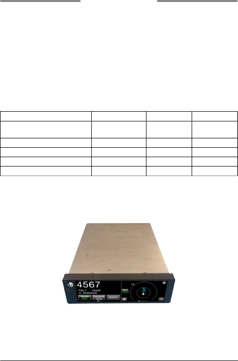
1-1: Lynx NGT-9000s .............................................................................................................................. 1-1
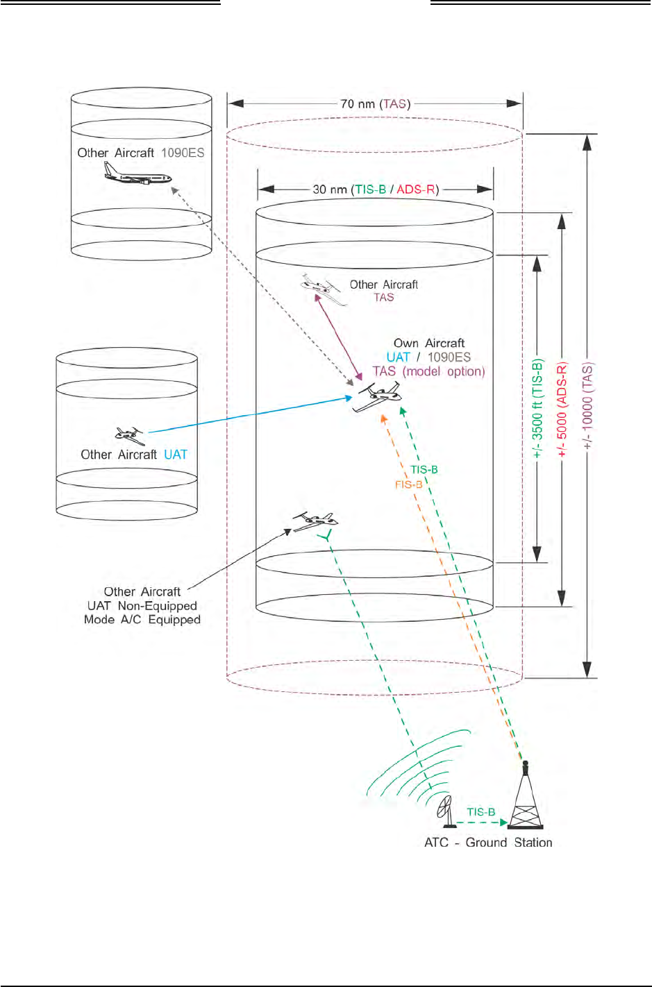
1-2: Example of Own Aircraft UAT, 1090ES, and TAS Traffic ................................................................ 1-5
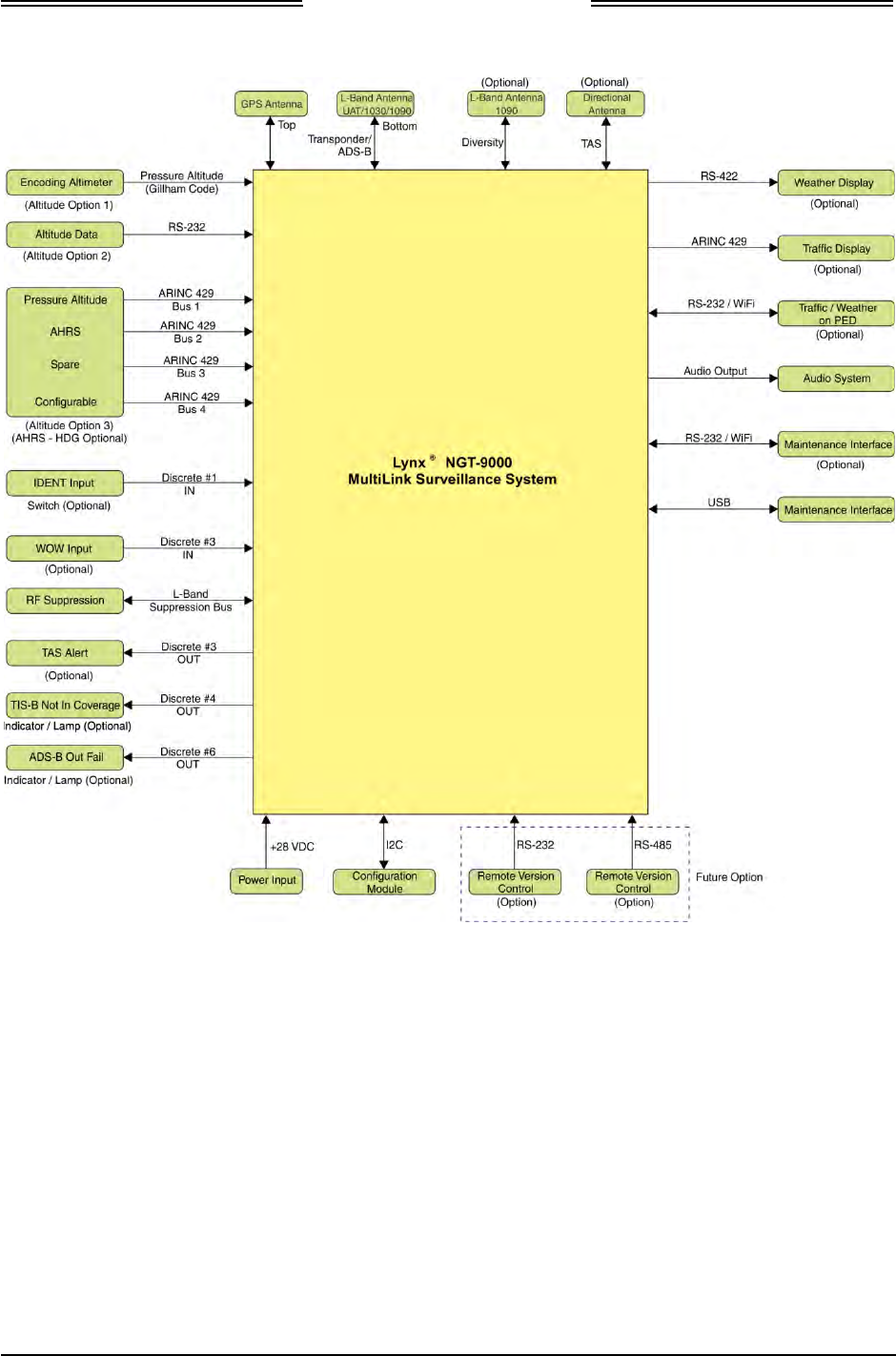
1-3: System Block Diagram..................................................................................................................... 1-8
2-1: Outline Dimensions for Panel Mount NGT-9000 ............................................................................. 2-4
2-2: Outline Dimensions for Mounting Rack ........................................................................................... 2-5
2-3: Interconnect Wiring Diagram ......................................................................................................... 2-10
2-4: Mating Connector (P1) and Pin Assignments ................................................................................ 2-13
2-5: P1 Mating Connector Assembly .................................................................................................... 2-14
2-6: Outline Dimensions for the Data Configuration Module (9230-17003-01) .................................... 2-15
2-7: Example of Assembled RF Cable .................................................................................................. 2-16
2-8: Coax Cable Preparation................................................................................................................. 2-17
2-9: Straight Coax Contact Shield Termination .................................................................................... 2-18
2-10: Right Angle Coax Contact Installation ......................................................................................... 2-18
2-11: Connector Assembly .................................................................................................................... 2-19
2-12: Panel Assembly ........................................................................................................................... 2-20
2-13: Example of Antenna Mounting Locations .................................................................................... 2-21
2-14: Directional Antenna Mounting Location ....................................................................................... 2-25
2-15: NY156 / NY164 Directional Antenna Outline Dimensions ........................................................... 2-26
2-16: Antenna Mounting Holes ............................................................................................................. 2-28
2-17: Directional Antenna Installation ................................................................................................... 2-28
3-1: Transponder/Traffic Screens ........................................................................................................... 3-1
3-2: Maintenance Application Tool – Main Page .................................................................................... 3-4
3-3: Lynx MAT – Main Screen ................................................................................................................ 3-4
3-4: Lynx MAT – Restart Unit .................................................................................................................. 3-5
3-5: Activate Maintenance Mode Window ............................................................................................... 3-6
3-6: Maintenance Mode Screens ............................................................................................................ 3-6
3-7: Lynx MAT – WiFi Accessory ............................................................................................................ 3-7
3-8: Lynx MAT – Check Versions .......................................................................................................... 3-8
3-9: Lynx MAT –Aircraft Specific Options ............................................................................................. 3-10
3-10: Lynx MAT – I/O Options – AHRS and Altitude ............................................................................ 3-13
3-11: Lynx MAT – I/O Options – Misc ................................................................................................... 3-14
3-12: Lynx MAT – Configuration - Backup ............................................................................................ 3-16
3-13: Lynx MAT – Setup - Calibration ................................................................................................... 3-17
3-14: Lynx MAT – Info – Fault Log ........................................................................................................ 3-18
3-15: Lynx MAT – Live Data - Inputs .................................................................................................... 3-19
3-16: Lynx MAT – Live Data - GPS ....................................................................................................... 3-20
3-17: Lynx MAT – Live Data - GPS ....................................................................................................... 3-21
3-18: Lynx MAT – Live Data - Simulate ................................................................................................ 3-22
3-19: Examples of Start-up Screens ..................................................................................................... 3-24
3-20: Example of Normal Operation ..................................................................................................... 3-24
3-21: Example of Flight ID Input Screen ............................................................................................... 3-24
3-22: Example of System Test Results ................................................................................................. 3-25
3-23: Options Screen… ......................................................................................................................... 3-26
3-24: Lynx MAT – Ground Test ............................................................................................................. 3-28
Page viii 0040-17001-01
January 15, 2015 Revision A

Lynx NGT-9000s
Installation Manual
List of Illustrations
Figure Page
4-1: Activate Maintenance Mode Window ............................................................................................... 4-2
4-2: Maintenance Mode Screens ............................................................................................................ 4-2
4-3: Lynx MAT – Update Software ........................................................................................................ 4-15
4-4: Lynx MAT – Update Database ....................................................................................................... 4-16
4-5: Lynx MAT – Information ................................................................................................................. 4-17
4-6: Lynx MAT – Version....................................................................................................................... 4-17
4-7: Lynx MAT –Configuration - Restore .............................................................................................. 4-27
4-8: Lynx MAT – Service ....................................................................................................................... 4-28
A-1: RN370M Interconnect Option for RS-232 to WiFi Converter ......................................................... A-2
0040-17001-01 Page ix
Revision A January 15, 2015

Lynx NGT-9000s
Installation Manual
List of Tables
Table Page
1-1: System Components........................................................................................................................ 1-1
1-2: Built-in Interfaces ............................................................................................................................. 1-7
1-3: Specifications for Lynx NGT-9000s ............................................................................................... 1-12
1-4: Specifications for Detachable configuration module ...................................................................... 1-14
1-5: Applicable TSO’s ........................................................................................................................... 1-15
1-6: TSO Markings ................................................................................................................................ 1-16
1-7: TSO Deviations .............................................................................................................................. 1-17
1-8: Failure Classification ...................................................................................................................... 1-19
1-9: Hardware Modifications ................................................................................................................. 1-19
1-10: Software Revisions ...................................................................................................................... 1-20
1-11: Equipment List ............................................................................................................................. 1-21
1-12: Installation Kit P/N 9060-17000-01 for Straight RF Connector .................................................... 1-24
1-13: Installation Kit P/N 9060-17000-02 for Right Angle RF Connector ............................................. 1-24
1-14: Coaxial Cable Specifications ....................................................................................................... 1-25
1-15: Directional Antenna SIGMA and DELTA Port Cable Vendors .................................................... 1-26
1-16: Cable to Connector Reference .................................................................................................... 1-27
1-17: GPS Antennas ............................................................................................................................. 1-28
1-18: L-Band Antennas ......................................................................................................................... 1-28
1-19: Directional Antenna Model Options and Specifications ............................................................... 1-29
1-20: Directional Antenna Installation Kit 817-10009-xxx ..................................................................... 1-30
1-21: Airframe Installation Kits .............................................................................................................. 1-30
1-22: Traffic Displays ............................................................................................................................ 1-31
1-23: FIS-B WX Displays ...................................................................................................................... 1-31
1-24: RS-232 to WiFi Accessories ........................................................................................................ 1-31
1-25: APPS for PED .............................................................................................................................. 1-32
1-26: List of Service Notices ................................................................................................................. 1-34
1-27: System Software CD Part Numbers and Contents ...................................................................... 1-35
4-1: Troubleshooting ............................................................................................................................... 4-3
4-2: System Status Messages ................................................................................................................ 4-9
4-3: List of Fault Log Messages ............................................................................................................ 4-18
A-1: Connector (P1) Pin Assignments ................................................................................................... A-8
Page x 0040-17001-01
January 15, 2015 Revision A

Lynx NGT-9000s
Installation Manual
Abbreviations, Acronyms, and Symbols
ITEM
DEFINITION
° Degrees
°C Degrees Celsius
°F Degrees Fahrenheit
1090ES 1090 megahertz extended squitter
AC Advisory Circular
ACSS Aviation Communication and Surveillance Systems
ADS-B Automatic Dependent Surveillance-Broadcast
ADS-R Automatic Dependent Surveillance - Rebroadcast
AHRS Attitude & Heading Reference System
AIRB Basic Airborne Situation Awareness
ARINC Aeronautical Radio, Incorporated
ASA Aircraft Surveillance Applications
ASSAP Airborne Surveillance and Separation Assurance Processing
ATC Air Traffic Control
ATCRBS Air Traffic Control Radar Beacon System
ATM Air Traffic Management
AWG American Wire Gauge
BIT Built In Test
Cal Calibration
CCW Counter Clock Wise
CDTI Cockpit Display of Traffic Information
CFR Code of Federal Regulations
CONUS Continental United States
CW Clock Wise
dB Decibel
dBm Decibels referenced to one Milli-watt
dc Direct Current
DCM Detachable Configuration Module
DL Data Loading
DME Distance Measuring Equipment
DO- RTCA Document Number Prefix (i.e., DO-160)
DTIF Display Traffic Information File
EMI Electro-Magnetic Interference
EVAcq Enhanced Visual Acquisition Application
FAA Federal Aviation Administration
FAR Federal Aviation Regulations
FCC Federal Communications Commission
FIS-B Flight Information Services - Broadcast
FPGA Field Programmable Gate-Array
FSS Flight Service Station
0040-17001-01 Page xi
Revision A January 15, 2015

Lynx NGT-9000s
Installation Manual
Abbreviations, Acronyms, and Symbols
ITEM
DEFINITION
Ft feet
FW Firmware
g Gravitational Acceleration
GPS Global Positioning System
H/W Hardware
hPa Hectopascal
Hz
Hertz
i.e. That is
IAW In Accordance With
ID Identification
in Hg Inches of Mercury
Kg Kilogram
kHz
Kilohertz
Kts Knots
L-3 AS L-3 Communications Avionics Systems
LLC Limited Liability Company
LRU Line Replaceable Unit
Lynx MAT Maintenance Application Tool
m Meter
Max Maximum
MSG Message
MHz Megahertz
mm Millimeter
MPC Maintenance Personal Computer
MSS
MultiLink Surveillance System
N/A Not Applicable
NACp Navigation Accuracy Category for position
NAR Non Altitude Reporting
NAS National Airspace System
NC Not Connected
NEXRAD
Next Generation Radar Reflectivity
NGT Not an abbreviation
NIC Navigation Integrity Category
No. Number
NOTAM Notice to Airmen
NVM Non-Volatile Memory
Orig Original
P/N Part Number
PBIT Periodic Built-In Test
PED Personal Electronic Device
PFD Primary Flight Display
Page xii 0040-17001-01
January 15, 2015 Revision A

Lynx NGT-9000s
Installation Manual
Abbreviations, Acronyms, and Symbols
ITEM
DEFINITION
RAIM Receiver Autonomous Integrity Monitoring
RBA Risk-Based Authentication
RF Radio Frequency
RTCA RTCA, Inc.
S/N Serial Number
S/W Software
SBAS
Satellite Based Augmentation systems
SPI Special Position Identification
STC Supplemental Type Certification
STIF Standard TCAS Intruder File
SUA Special Use airspace
SURF Basic Surface application
TAF
Terminal Area Forecasts
TAS Traffic Advisory System
TCAS Traffic Alert and Collision Avoidance System
TFR Temporary Flight Restrictions
TIS-B Traffic Information Service – Broadcast
TSAA Traffic and Situational Awareness Alerts
TSO Technical Standard Order
UAT Universal Access Transceiver
USB Universal Serial Bus
UTC Coordinated Universal Time
Vdc Volts Direct Current
VFR Visual Flight Rules
VHF Very High Frequency
VOR VHF Omni-directional
W Watts
WAAS Wide Area Augmentation System
WiFi Wireless Fidelity
WOW Weight On Wheels
Wx Weather
0040-17001-01 Page xiii
Revision A January 15, 2015

Lynx NGT-9000s
Installation Manual
This page intentionally blank
Page xiv 0040-17001-01
January 15, 2015 Revision A
Lynx NGT-9000s
Installation Manual
Section
1
General Information
1.1 INTRODUCTION
This section includes descriptions, specifications, TSO information, equipment required but not supplied,
and installation approval and limitations for the Lynx® MultLink Surveillance System Lynx NGT-9000s
family (Release 1) See Figure 1-1. Available models of the Lynx NGT-9000s are detailed in Table 1-1.
Included at the end of this section is a list of compatible equipment and equipment required but not
supplied with the system.
Table 1-1: System Components
COMPONENT MODELS H/W PART NO. S/W PART NO.
MultiLink Surveillance System NGT-9000+ (1)
NGT-9000D (1) 9029000-20000 9020010-001 (2)
Detachable Configuration Module DCM 9230-17003-01 - -
GPS Antenna See Table 1-17 - - - -
L-Band Antenna See Table 1-18 - - - -
Directional Antenna (optional) See Table 1-19 - - - -
Notes:
(1) The NGT-9000D and NGT-9000+ require an unlock code that is set up during installation. See paragraph1.3.3.
(2) Details on software releases are located in paragraph 1.9.
(3) The “+” at the end of the model number indicates TAS functionality. The “D” at the end of the model number
indicates Diversity functionality.
Figure 1-1: Lynx NGT-9000s
0040-17001-01 General Information Page 1-1
Revision A January 15, 2015

Lynx NGT-9000s
Installation Manual
1.2 FUNCTIONAL DESCRIPTION
The Lynx MultiLink Surveillance System (also referred to in this manual as the Lynx NGT-9000s) is a
Mode S Level 2 dens Class 1 Transponder with an integrated GPS receiver providing Automatic
Dependent Surveillance-Broadcast (ADS-B) output using a 1090ES (Extended Squitter). The unit also
receives ADS-B data via 1090ES and UAT (978 MHz Universal Access Transceiver). Some models
support optional Active Traffic Awareness System (TAS) or antenna Diversity functionality.
The unit replies to Mode A, Mode C and Mode S interrogations receiving interrogations at 1030 MHz and
transmitting responses at 1090 MHz. The unit is equipped with IDENT capability that activates the
Special Identification (SPI) pulse for 18 seconds.
Ground stations can interrogate Mode S Transponders individually using a 24-bit ICAO Mode S address,
which is unique to the particular aircraft. In addition, ground stations may interrogate the unit for its
transponder data capability and the aircraft's Flight ID.
The ADS-B provides own aircraft data with Enhanced Visual Acquisition (EVAcq) traffic information
that improves situational awareness and flight safety by providing aircraft position, velocity, and heading
information that is automatically transmitted to other aircraft and ground stations providing immediate
surveillance of air-to-air traffic.
The 1090ES and UAT ADS-B datalink have the following capabilities:
• 1090ES In - Receive ADS-B, ADS-R and TIS-B
• 1090ES Out - Transmit ADS-B
• UAT In - Receives ADS-B, ADS-R and TIS-B, FIS-B, NOTAMS, and TFR’s
The unit also provides TAS traffic advisories when TAS configuration is enabled. A voice or tone audio
output announces traffic alerts. The unit has multiple transmit/receive ARINC 429, RS-422 and RS-232
data ports used to transmit data to traffic, weather, and PED displays.
The unit provides the transponder code, reply symbol and mode of operation to the display.
Maintenance and configuration setup can be accomplished via the USB port located on the front of the
unit or by an optional WiFi connection.
Models are available that provide Active Traffic Awareness System (TAS) function and antenna
Diversity. Both models require additional equipment to be installed.
1.2.1 GPS Functional Overview
The GPS function utilizes signals from Global Positioning System (GPS) satellite constellation and
Satellite-Based Augmentation Systems (SBAS) such as the USA Wide Area Augmentation System
(WAAS), European EGNOS, Indian GAGAN and the Japanese MSAS. Currently it supports WAAS and
WAAS compatible SBAS systems.
The internal GPS function provides position, velocity, time, and integrity (NIC, NAC etc.) information to
the ADS-B functions and is ADS-B rule compliant with the requirements of AC20-165A.
Page 1-2 General Information 0040-17001-01
January 15, 2015 Revision A

Lynx NGT-9000s
Installation Manual
1.2.2 ADS-B System Overview
The Automatic Dependent Surveillance-Broadcast (ADS-B) improves situational awareness and flight
safety by providing real time traffic information. The ADS-B In function is used to receive ground station
supported TIS-B and ADS-R traffic, and direct communication with nearby like equipped aircraft (with
Mode S or UAT). The ADS-B Out (1090ES) function is used to periodically broadcast (without
interrogation) information about the aircraft that includes aircraft identification, position, altitude, velocity
and other aircraft status information.
• The traffic display shows the relative position of ADS-B or standard traffic using text, shapes, and
colors. ADS-B also provides similar information on ADS-B equipped ground vehicles.
• The effective surveillance range is 60 nmi. The passive-mode surveillance range is 160 nmi and
maintains report messages for a minimum of 200 1090ES ADS-B participants and 300 UAT ADS-B
participants simultaneously. To reduce display clutter a set number of other aircraft of the highest
priority other aircraft are displayed at a time. See Figure 1-2 for an example of own aircraft traffic
(UAT, 1090ES, TIS-B, and TAS).
• The Lynx NGT-9000 is equipped with a dual-link receiver. ADS-R service is unnecessary to provide
a complete picture of traffic in the area.
1.2.3 ADS-R System Overview
The Automatic Dependent Surveillance – Re-broadcast (ADS-R) is a ground based broadcast service that
repeats ADS-B messages from one link (1090ES or UAT) to the other link for aircraft with ADS-B In.
• ADS-R transmissions are updated at least every 2 seconds on the surface, 5 seconds in the terminal
area, and 10 seconds in the en-route airspace.
• An aircraft on the ground receiving ADS-R is provided both ground aircraft and vehicles as well as
airborne other aircraft within 5nm and 2,000 ft above ground level of the airport reference point.
• Other aircraft are provided by the ground station if within a 15 nm horizontal range and +/-5,000 ft
of altitude of the receiving aircraft. ADS-B equipped ground aircraft and vehicles are not displayed
to airborne aircraft. See Figure 1-2 for an example of own aircraft traffic (UAT, 1090ES, TIS-B, and
TAS).
1.2.4 TIS-B System Overview
Traffic Information Service Broadcast (TIS-B) is a ground based broadcast service that provides
secondary surveillance radar (SSR) derived traffic data (aircraft not equipped with ADS-B Out capability)
to ADS-B In equipped aircraft.
• The actual availability of services depends upon the availability of ground-based radar to support
TIS-B source data.
• Receiving aircraft must be in both radar coverage and ground based transceiver (GBT) coverage in a
given area to receive TIS-B service in that area. When ownship is above 24,000 ft, the ground station
will no longer provide TIS-B service. To reduce display clutter, the TIS-B service provides traffic
information on other aircraft within 15 nmi and +/- 3500 ft of ownship.
• Other aircraft are provided by the ground station if within a 15nm horizontal range and +/-3,500 ft of
altitude of the receiving aircraft. ADS-B equipped ground aircraft and vehicles are not displayed to
airborne aircraft. See Figure 1-2 for an example of own aircraft traffic (UAT, 1090ES, TIS-B, and
TAS).
0040-17001-01 General Information Page 1-3
Revision A January 15, 2015

Lynx NGT-9000s
Installation Manual
1.2.5 FIS-B System Overview
The Flight Information Services - Broadcast (FIS-B) function provides pilots with a cockpit display of
certain aviation weather and aeronautical information for awareness of own aircraft location with respect
to reported weather, including hazardous meteorological conditions (CONUS/ NEXRAD /AIRMETS/
SIGMETS/ NOTAMS/ METARS, etc) and SUA status and TAF (FIS-B products).
NOTE
CONUS and Regional NEXRAD may not always contain complete data.
The data is refreshed every 15 minutes and it is likely to be updated in a
future cycle.
FIS-B is advisory information only and is intended to enhance pilot decision-making during strategic
flight planning. FIS-B augments traditional sources of this information such as ATC and Flight Service
Station (FSS). FIS-B information is provided over the ADS-B Services network on the 978 MHz UAT
link when in ground station coverage.
1.2.6 Traffic Awareness System (option) Overview
The TAS option is an active system that operates as an aircraft-to-aircraft interrogation device. The unit
interrogates transponders in the surrounding airspace similar to ground based radar. When replies to these
active interrogations are received, the responding aircraft’s range, altitude, and closure rates are computed
to plot traffic location and predict collision threats. The unit alerts the flight crew to nearby transponder
equipped aircraft and assists the pilot in the visual acquisition of aircraft that may represent a danger.
Traffic information, out to a selected range, is graphically displayed on the unit or alternate display. See
Figure 1-2 for an example of own aircraft traffic (UAT, 1090ES, TIS-B, and TAS).
• The system display shows the relative position of traffic using text, shapes (i.e., Traffic Advisory =
solid circle; Other Traffic = open diamond) and colors.
• The effective active-mode surveillance range is 35 nmi and track 35 ATCRBS intruders
simultaneously with the target bearing relative to the nose of own aircraft.
• The tracking of targets is in a cylindrical volume centered on own aircraft that has, at a minimum, a
radius of 35 nmi and extends 10,000 ft above and 10,000 ft below own aircraft.
1.2.7 Discrete Inputs and Outputs
The Lynx NGT-9000s have discrete inputs and outputs available that can be interfaced to indicator lamps
and cockpit switches. These are optional installations and are not required.
• The WOW input discrete signals the On Ground status to the unit via a squat switch, airspeed
monitor, or a collective switch.
• The IDENT switch activates the IDENT pulse which highlights the aircraft’s symbol on the ATC’s
radar screen and is identified on the NGT-9000 when active.
• The Audio Mute switch is used to signal the unit to suppress all audio output. The discrete is set to
GND/Open. The active position indicates Audio Muted. When grounded this input mutes all audio
from the NGT-9000. This input is typically only used if the aircraft equipped with TAWS or other
aircraft alerting systems.
• The TAS Alert lamp is used to indicate Traffic Alert (TA). The discrete is set to GND/Open. The
GND (active) position indicates Traffic Alert. The GND (active) position illuminates the lamp.
• The TIS-B Not In Coverage lamp is used to indicate that the unit is not receiving a ground station
signal. The discrete is set to GND/Open. The GND (active) position illuminates the lamp.
• The ADS-B Out Fail lamp is used to indicate that ADS-B out is not operating. The discrete is set to
GND/Open. The GND (active) position illuminates the lamp. Depending on the situation the lamp
has the following functions: flashes while the GPS is initializing and stays illuminated when the
ADS-B Out has failed.
Page 1-4 General Information 0040-17001-01
January 15, 2015 Revision A
Lynx NGT-9000s
Installation Manual
Figure 1-2: Example of Own Aircraft UAT, 1090ES, and TAS Traffic
0040-17001-01 General Information Page 1-5
Revision A January 15, 2015

Lynx NGT-9000s
Installation Manual
1.3 EQUIPMENT DESCRIPTIONS
The Lynx MultiLink Surveillance System includes a Detachable Configuration Module (DCM). A panel
mounted rack is required for installation. Additional 3rd party components are necessary to complete the
installation. Refer to paragraph 1.5 for component requirements and installation considerations. Details on
these components are provided in paragraph 1.11.
The unit has a bezel containing a multifunction touch screen that is designed to fit into a MARK width
panel. LED backlighting is controlled by either the auto-dimming functionality provided by the ambient
light sensor or using the pilot adjustable brightness control. The unit is equipped with a main sub-D
connector (J1) and RF connectors. A USB port is available to establish communication between the unit
and a maintenance computer for installation and maintenance activities.
The multifunction touch screen has full operational control providing the means to select screen views
and interface with transponder, traffic, and weather information. The following information is available
for display and control:
• Flight ID or aircraft Tail Number
• Transponder and Traffic Mode of Operation
• ADS-B Status
• VFR Select and Squawk Code Input
• IDENT
• Traffic (graphic and textual)
• Weather (graphic and textual)
• TAS Mode (model specific)
1.3.1 Model Options
The Diversity option offers enhanced traffic awareness receiving data via 1090MHz using the ADS-B
service.
The Traffic Awareness System (TAS) option provides additional traffic awareness when ADS-B
equipped aircraft are not in the area providing Traffic Alert (TA) warnings to the flight crew. See
paragraph 1.2.6 for TAS functionality.
The Diversity and TAS options require an unlock codes that are entered using the Lynx MAT.
Models with Diversity require the installation of an additional L-Band antenna. The TAS option requires
the installation of a directional antenna.
1.3.2 Detachable Configuration Module (DCM)
The DCM part number 9230-17003-01 is part of the Lynx NGT-9000s and is used for the storage of
configuration data. The DCM is permanently installed with the wire harness and interfaces to the unit via
a 4 wire interface from the DCM.
The configuration settings are stored in the unit’s non-volatile memory and are entered via commands
sent over the maintenance interface to configure such items as; input / output interface options, aircraft
specific options (including TAS and Diversity), and installation calibration parameters.
When the configuration data is set, Lynx NGT-9000s units may be swapped and the configuration
remains with the aircraft.
Page 1-6 General Information 0040-17001-01
January 15, 2015 Revision A

Lynx NGT-9000s
Installation Manual
1.3.3 System Unlock Code
Unlock codes are required if installing and activating the TAS and Diversity options. The unlock codes
are 10 digit codes that are entered during installation using the Lynx MAT to install either of these
options. The unlock codes may be purchased and shipped with the unit. If the unlock code is not included,
contact L-3 Avionics Systems Customer Service to obtain the code. Be sure to have the Mode-S ID (e.g.
ICAO) available for the service representative. The unlock code is associated with the aircraft ICAO
address and will only work for that aircraft ID.
1.4 INTERFACES
The unit supports a number of built-in interfaces as described in Table 1-2. A system block diagram is
provided in Figure 1-3. Additional information on these interfaces is detailed below. Refer to Appendix A
for interface options and the installation section for an interconnect diagram.
Table 1-2: Built-in Interfaces
Interface (No.) Function
ARINC 429 Input (4) Receive ADC and AHRS data
ARINC 429 Output (1) Transmit to a traffic display
Discrete Inputs (17) Receive Gillham Altitude Encoder, Audio Mute, IDENT
Command, and In Air / On Ground (WOW) status
Discrete Output (9) Transmit ADS-B Out Fail, TIS-B Out of Coverage, Traffic Alert
output
RS-232 Input / Output (4) Wi-Fi accessory port
RS-232 Input (1) Altitude Encoder port
RS-422 Input / Output (1) External display port
RF Suppression Input / Output (1) Provides on aircraft suppression of the L-band equipment
Analog Audio Output (1) Connects to Audio Panel un-muted input.
I2C Port (1) Detachable configuration module
GPS Antenna Port Connect to a top mount antenna providing GPS data to support
ADS-B functionality
L-Band Antenna Port Connects to the bottom mount antenna. Provides UAT 978
MHz input, 1030/1090 MHz extended squitter input/output to
support ADS-B/ATAC Transponder functionality.
Extra Antenna Ports Connects to a top mounted antenna (L-Band or Directional)
providing optional TAS or Diversity functionality.
Note: Not all interfaces are used. Some are spares, reserved for future use, or optional.
0040-17001-01 General Information Page 1-7
Revision A January 15, 2015
Lynx NGT-9000s
Installation Manual
Figure 1-3: System Block Diagram
1.4.1 ADS-B Out Fail
The ADS-B Out Fail is a discrete output that provides an indication of when there is a loss of ADS-B Out.
The discrete output is a ground/open type and is able to sink 250mA.
1.4.2 AHRS Input
An optional ARINC 429 input is provided to interface to an AHRS (heading) system in order to provide
data for Enhanced Surveillance (EHS) and ADS-B data.
1.4.3 Altitude Encoder Input
Altitude input is required on either and an RS-232 input port, 11 Wire Gillham Input Port or ARINC 429
Input Port.
Page 1-8 General Information 0040-17001-01
January 15, 2015 Revision A

Lynx NGT-9000s
Installation Manual
1.4.4 Audio Out
Two audio out discrete outputs are available that can output a 40 mW signal to equipment with a load of
600 Ohms.
1.4.5 RF Suppression Input/output
The mutual suppression input/output is used to provide suppression of L-band equipment on the aircraft.
The transponder uses the signal as an input to inhibit decoding of receiver signals when other equipment
on the aircraft is transmitting. When the transponder transmits, it asserts a positive voltage on the output
to provide the suppression to other systems on the airplane.
1.4.6 TAS Alert
Traffic Alert is a discrete output that provides an indication of when a TAS Alert exists. Discrete outputs
are ground/open type and are able to sink 250mA.
1.4.7 TIS-B Not In Coverage
The TIS-B Not In Coverage discrete output provides an indication that the unit is not in an Radar
coverage area or that power has been removed from the unit. Discrete outputs are ground/open type and
are able to sink 250mA.
1.4.8 WiFi Interface
The Unit uses a RS-232 bus to interface with a commercially available RS-232 to Wifi accessory. This
interface provides traffic and weather information on a personal electronic device via an approved
software application (APP).
1.4.9 WOW Input
The WOW input discrete is optional. The input signals the On Ground status to the unit via squat switch,
Airspeed monitor, or a collective switch. The discrete input is active (ON) when the input is grounded.
• Do not connect this to a gear switch or a manual pilot switch input.
• An internal algorithmic override that uses ground speed and altitude inputs may override this input
and change the air/ground state (ex. a WOW "in-air" state could get changed back to on ground if the
Aircraft is sitting on the ground). This is expected behavior. If simulated in-air tested is required,
use the ground test mode.
1.4.10 Maintenance Interface
The Unit can interface to a maintenance computer using either the WiFi interface or the USB port located
on the front of the unit. This interface is used for installation setup and fault isolation and is only available
while on ground.
1.4.11 GPS Antenna
Antenna performance is critical to the operation of the Unit. The unit requires that the GPS Antenna meet
performance requirements specified in TSO-145c.
0040-17001-01 General Information Page 1-9
Revision A January 15, 2015

Lynx NGT-9000s
Installation Manual
1.4.12 L-Band (978/1030/1090 MHz) Antenna
The L-Band antenna is used by the Unit to receive 978 MHz, 1030 MHz, and transmit/receive 1090 MHz.
The unit requires that the L-Band Antenna meet performance requirements specified in DO-181E and
DO-282B Section 2.2.14.
If the NGT-9000 is configured for Diversity, then two L-Band antennas are required.
1.4.13 Directional Antenna
L-3 Avionics Systems has two models of Directional Antenna available: the NY156 (P/N 805-10003-001)
and model NY164 (P/N 805-10890-001).The teardrop-shaped antenna is sealed against environmental
extremes and used by the Unit to receive Active Traffic (TAS) information.
1.4.14 Traffic Display
Traffic information is output to a compatible traffic display from the unit using an ARINC 735B interface
format. Possible traffic output format selections include Standard TCAS Intruder File (STIF or TIF) and
Display Traffic Information File (DTIF). The unit allows installed configuration selection of STIF, DTIF,
or both formats of output data via the ARINC 429 bus to the traffic display.
1.4.15 Weather Display
The Unit interfaces to supported FIS-B Wx displays via a RS-422 Input and Output data bus.
Page 1-10 General Information 0040-17001-01
January 15, 2015 Revision A

Lynx NGT-9000s
Installation Manual
1.5 INSTALLATION CONSIDERATIONS
The installation of the following equipment is the minimum required by the Unit to provide ADS-B
functionality as well as the optional TAS and Diversity functionality.
• Each installation requires at a minimum the following equipment installed:
1. Lynx NGT-9000s
2. Detachable configuration module
3. GPS Antenna
4. L-Band (978/1030/1090 MHz) Antenna
5. Altitude Source (ARINC 429, RS-232, or Gilham Code)
• A Unit with TAS (model: NGT-9000+) also requires the following:
1. Unlock code to unlock TAS option via the Lynx MAT
2. Directional Antenna (NY156 or NY164)
• A Unit with Diversity (model: NGT-9000D) also requires the following:
1. Unlock code to unlock Diversity option via the Lynx MAT
2. Additional L-Band Antenna, located on the top of the aircraft.
0040-17001-01 General Information Page 1-11
Revision A January 15, 2015

Lynx NGT-9000s
Installation Manual
1.6 SPECIFICATIONS
Table 1-3: Specifications for Lynx NGT-9000s
PART NUMBERS: 9029000-20000
CERTIFICATION: USA (FAA): TSO-C112d, C113a, C145c, C147, C154c, C157a, C166b, C195a.
See paragraph 1.7 for specific TSO information.
Listed are current authorizations at time of publication, contact Field Service Engineering for
latest certification information
ADVISORY CIRCULARS: AC20-21-46, AC20-115B, AC20-152, AC20-165A, AC20-172A
RTCA COMPLIANCE: Environmental Category: DO-160G (See Environmental Qualification Form in Appendix B.)
Software Category: DO-178B, Design Assurance Level C
Hardware Category: DO-254, Design Assurance Level C
Other: DO-181E, DO-197A, DO-229D, DO-260B, DO-267A, DO-282B, DO-317A,
ARINC 718A-4 and SAE AS8034B.
COMPLIANCE: ATC transponder functionality: 14 CFR 91.215, 91.217, 91.413
ADS-B Out functionality: 14 CFR 91.225, and 91.227
The Lynx NGT-9000s has been shown to meet the requirements in TSO-C166b and meets
the requirements of 14 CFR 91.227 installed in accordance with these installation
instructions.
SIZE: Case
Width 1.48 inches [12.83 cm] MAX
Height: 5.75 inches [7.42 cm] MAX
Depth*: 8.99 inches [3.81 cm] MAX
Bezel
Width 6.25 inches [13.44 cm] MAX
Height: 1.8 inches [7.62 cm] MAX
* Does not include connectors.
Note: Unit Fits into a “MARK width” panel.
WEIGHT: Nominal 1.0 Lbs (0.5 kg) Maximum 4.0 Lbs (0.8 kg)
CHASSIS GROUND: Bonding impedance between aircraft ground and the Lynx NGT-9000s Chassis must be less
than 2.5 milliohms.
POWER REQUIREMENTS: +14.0 VDC nominal. 19.0 watts nominal (24.0 watts maximum)
+28.0 VDC nominal. 19.0 watts nominal (24.0 watts maximum)
ELECTRICAL CONNECTORS: • 78 position d-subminiature connector receptacle (shell size 5) with swaged float plate.
Connector insert per MIL-DTL-24308, Appendix A, Figure A-5, Arrangement 2.
Connector insert shall accommodate 22D removable crimp contacts (socket) per
M39029/57-324, or equivalent.
• RF Connectors: 5W5 Coax D-Sub
• Mini-B USB: Maintenance Port
INTERFACE (S): • ARINC 429
• RS-422
• RS-232
• Discrete Input/Outputs
• RF Suppression Bus
• I2C serial interface (detachable configuration module interface)
Note: Refer to Appendix A for signal names and characteristics
Page 1-12 General Information 0040-17001-01
January 15, 2015 Revision A

Lynx NGT-9000s
Installation Manual
Table 1-3: Specifications for Lynx NGT-9000s
OPERATING TEMPERATURE: -20° to +55°C (-4° to +131°F)
STORAGE TEMPERATURE: -55° to +85°C (-67° to +185°F)
MAXIMUM ALTITUDE: 55,000 ft (installation environment)
FUNCTIONALITY: • Mode S Transponder
• Global Positioning System (GPS)
• UAT/1090ES ADS-B In
• 1090ES ADS-B Out: Automatic Dependent Surveillance – Broadcast
• Traffic Awareness System (TAS) (optional)
OPERATION: Start Up Time: On Ground 20 seconds or less
In air 5 seconds or less.
Display Luminance: Range 0.05 fl to 150 fl
Built In Test: Fault Monitoring on all stages of operation from start up to
power down.
UAT Receiver Sensitivity
(Class A1S) -95.0dBm for 90% Message Decoding for Long ADS-B
Messages
-96.0dBm for 90% Message Decoding for Short ADS-B
Messages
-93.0dBm for 90% Message Decoding for Ground Uplink
Messages
Mode S Transponder Power (Class 1 Transponder). 125W minimum, 250 W maximum.
TAS Output Power (Class A TAS). 125W minimum, 250 W maximum.
SCHEDULED MAINTENANCE: The Lynx NGT-9000s is a transponder device and must be tested and inspected every 24
months subject to the requirements of FAA documents 14 CFR Part 43 Appendix F.
SERVICE LIFE: The Lynx NGT-9000s has unlimited service life.
REPAIRABILITY: Repairs performed at the FAA certificated Repair Station co-located at the OEM
(equipment) facility.
0040-17001-01 General Information Page 1-13
Revision A January 15, 2015

Lynx NGT-9000s
Installation Manual
Table 1-4: Specifications for Detachable configuration module
PART NUMBER: 9230-17003-01
CERTIFICATION: USA (FAA): TSO-C145c, C154c, C157a, C195a.
See paragraph 1.7 for specific TSO information.
Listed are current authorizations at time of publication, contact Field Service Engineering for
latest certification information
RTCA COMPLIANCE: The DCM is tested as part of the NGT-9000.
WEIGHT: Negligible
SIZE: Length: 6 inches (includes wires)
POWER REQUIREMENTS: 3.3 Vdc (regulated via J1 connector)
INTERFACE (S): I2C serial interface
OPERATING TEMPERATURE: -40° to +70°C (-40° to +158°F)
STORAGE TEMPERATURE: -55° to +85°C (-67° to +185°F)
MAXIMUM ALTITUDE: 55,000 ft (installation environment)
SCHEDULED MAINTENENACE: None.
SERVICE LIFE: Unlimited.
REPAIRABILITY: Replacement only.
Page 1-14 General Information 0040-17001-01
January 15, 2015 Revision A

Lynx NGT-9000s
Installation Manual
1.7 TSO INFORMATION
NOTE
Unless otherwise specified Release 1 refers to Release 1.0 and any
subsequent minor changes to Release 1.0.
The NGT-9000D Release 1 and DCM Release 1 meet the requirements of the following TSO’s.
Table 1-5: Applicable TSO’s
TSO NO. FUNCTION TSO TITLE
TSO-C112d ATCRBS / MODE S
Airborne Equipment Air Traffic Control Radar Beacon System/Mode Select
(ATCRBS / MODE S) Airborne Equipment
TSO-C113a Electronic Display Airborne Multipurpose Electronic Displays
TSO-C145c GPS SBAS Output Airborne Navigation Sensors Using The Global Positioning
System Augmented By The Satellite Based Augmentation
System
TSO-C147 TAS System Traffic Advisory System (TAS) Airborne Equipment
TSO-C154c UAT-IN Universal Access Transceiver (UAT) Automatic Dependent
Surveillance-Broadcast (ADS-B) Equipment Operating on
Frequency of 978 MHz
TSO-C157a FIS-B Display Aircraft Flight Information Services-Broadcast (FIS-B) Data
Link Systems and Equipment
TSO-C166b 1090ES MHz ADS-B
and TIS-B equipment Extended Squitter Automatic Dependent Surveillance -
Broadcast (ADS-B) and Traffic Information Service -
Broadcast (TIS-B) Equipment Operating on the Radio
Frequency of 1090 Megahertz (MHz)
TSO-C195a ADS-B System Avionics Supporting Automatic Dependent Surveillance –
Broadcast (ADS-B) Aircraft Surveillance Applications (ASA)
0040-17001-01 General Information Page 1-15
Revision A January 15, 2015

Lynx NGT-9000s
Installation Manual
1.7.1 TSO Markings
The following information summarizes the TSO application for the NGT-9000D Release 1 and DCM
Release 1.
Table 1-6: TSO Markings
TSO No. TSO MARKING TSO TITLE
C112d Level 2 dens Class 1 Air Traffic Control Radar Beacon System/Mode Select
(ATCRBS/Mode S) Airborne Equipment
C113a Airborne Multipurpose Electronic Displays SAE
AS8034B, Multipurpose Display
C145c Class Beta 1 Airborne Navigation Sensors Using The Global
Positioning System Augmented By The Satellite Based
Augmentation System
C147 Class A Traffic Advisory System (TAS) Airborne Equipment, DO-
197A, Traffic Advisory System
C154c Class A1S Receive Only Universal Access Transceiver (UAT) Automatic
Dependent Surveillance- Broadcast (ADS-B) Equipment
Operating on Frequency of 978 MHz
C157a Class 2 Aircraft Flight Information Services-Broadcast (FIS-B)
Data Link Systems and Equipment
C166b Class A2 Extended Squitter Automatic Dependent Surveillance -
Broadcast (ADS-B) and Traffic Information Service –
Broadcast (TIS-B) Equipment Operating on the Radio
Frequency of 1090 Megahertz (MHz)
C195a Class B1, B5, C1, C5 Avionics Supporting Automatic Dependent Surveillance –
Broadcast (ADS-B) Aircraft Surveillance Applications
(ASA)
Page 1-16 General Information 0040-17001-01
January 15, 2015 Revision A

Lynx NGT-9000s
Installation Manual
1.7.2 TSO Deviations from Minimum Performance Standards
The following information lists the TSOs for the unit that requires a deviation to Minimum Performance
Standards (MPS) that are called out in the TSO and provides the justification for the deviation.
Deviations to TSO-C147 are applicable to the diversity variants only. Deviations to TSO-C113a are
applicable to the panel mount variants only.
Table 1-7: TSO Deviations
TSO NO. DEVIATION
TSOC-145c, 3.d TSO requires use of DO-160E for environmental qualification testing; DO-
160G was used instead.
TSOC-147, 1.c TSO requires use of DO-160D for environmental qualification testing; DO-
160G was used instead.
TSO-C145c, 4.c
TSO-C147, 2.c
TSO-C154c, 4.d
TSO-C166b, 4.d
The Lynx NGT-9000s utilizes electronic part marking for the software part
number, which is stored in non-volatile memory.
TSO-C113a, 4.a
TSO-C145c, 4.a & 4.e
TSO-C147, 2.a
TSO-C154c, 4.a
TSO-C157a, 4.a
TSO-C166b, 4.a
TSO-C195a, 4.a
Per the guidance in FAA Order 8150.1c, the appliances are marked with the
primary TSO along with a reference to the Installation Manual for the other
TSO information (other applicable TSOAs, deviations, etc.).
TSO-C112d, 3.d
TSO-C166b, 3.d
The Lynx NGT-9000s has an RF transmitter which is used to generate both
the 1030MHz and 1090MHz waveforms for Mode S Transponder , ADS-B
Out, and TAS functions. Due to the RF power requirement and inherent non-
linearities in RF transmitters, the harmonics of the transmitter exceed the RF
radiated emissions limit in DO-160G. ACSS deviates from DO—160G
Section 21 Category M Radiated RF Emissions in the following frequency
bands when the transmitter is active:
2180MHz ± 7MHz (2nd Transmitter harmonic) Exceeds Cat M by as much
as 19.3dB
3270MHz ± 23MHz (3rd Transmitter harmonic) Exceeds Cat M by as much
as 22.0dB
4360MHz ± 23MHz (4th Transmitter harmonic) Exceeds Cat M by as much
as 24.4dB
5450MHz ± 23MHz (5th Transmitter harmonic) Exceeds Cat M by as much
as 21.4dB
0040-17001-01 General Information Page 1-17
Revision A January 15, 2015

Lynx NGT-9000s
Installation Manual
Table 1-7: TSO Deviations
TSO NO. DEVIATION
TSO-C147, 1.c Due to the RF power requirement and inherent non-linearities in RF
transmitters, the harmonics of the transmitter exceed the RF radiated
emissions limit in DO-160G. ACSS deviates from DO—160G Section 21
Category M Radiated RF Emissions in the following frequency bands when
the transmitter is active:
2060MHz ± 5MHz (2nd Transmitter harmonic) Exceeds Cat M by as much
as15.6dB.
3090MHz ± 5MHz (3rd Transmitter harmonic) Exceeds Cat M by as much as
16.7dB.
4120MHz ± 20MHz (4th Transmitter harmonic) Exceeds Cat M by as much
as 22.7dB.
5150MHz ± 5MHz (5th Transmitter harmonic) Exceeds Cat M by as much as
12.2dB
TSO-C112d The NGT-9000 does not perform Comm-A (broadcast or addressed) or
Comm-B Air-Initiated ADLP (Airborne Data Link Processor) link operations.
The NGT-9000 meets the certification of Level 2 transponders except for the
support of the above listed ADLP functions.
TSO-147 The use of traffic symbology as defined in DO-317A is equivalent level of
safety to the symbols define in TSO-C147.
ACSS submits that the use of the 0.1 inch character size for the TAS
characters (relative altitude tag) and use of 0.163 inch traffic symbols
provides an equivalent level of safety to the TSO-C147 specified character
and symbol sizes.
TSO-195a The ACSS ATCRBS and ADS-B traffic in a track-up orientation when
heading source is unavailable. ACSS believes that removing the ADS-B
traffic or ATCRBS traffic from the display when the heading input is not
available would significantly reduce the value of the CDTI’s support in the
pilot’s see and avoid responsibilities.
ACSS proposes the DO-317A ASA AIRB application display TIS-B traffic,
with a NACv of 0, as a non-directional track similar to EVAcq. This removes
the contradiction between requirements and is in-line with updates in the
next revision of the MOPS (i.e., DO-317B).
ACSS proposes the DO-317A ASA AIRB application display TIS-B traffic by
reporting the most recent non-zero NACv reading confirmed over a 60
second interval.
ACSS will set the EVAcq and AIRB functions unavailable when ownship
position is beyond 85 degrees North or South latitude. The result is a
display of “Traffic Unavailable” on Panel mount units and an indication of
“Standby” for remote displays. However, for NGT-9000 installations, where
TAS is enabled, the range/bearing based TAS targets are displayed.
1.7.3 Non-TSO Functions
The Non-TSO functions information provided here and below is to support FAA Order 8150.1B, section
17.c.(3) and Order 8110.4C Change 3, section 6-9.b.(2),(3) and are covered throughout this installation
manual as applicable. All Non- TSO functions are provided for situational awareness and are not
catastrophic or hazardous (per FAA Notice 8150.6 Section 5(f) (4)). Non-TSO functions are functions not
covered by a TSO approved Minimum Performance Standard/Specification (MPS) and are distinct and
independent, i.e., are not a supporting or additional feature of another TSO’s function.
The Lynx NGT-9000s and DCM do not have any Non-TSO functions.
Page 1-18 General Information 0040-17001-01
January 15, 2015 Revision A

Lynx NGT-9000s
Installation Manual
1.7.4 Failure Classification
Table 1-8 summarizes the potential hazards associated with the Lynx NGT-9000s functions and the
associated failure condition severity classifications per AC 23.1309-1E.
Table 1-8: Failure Classification
Functional
Description Hazard Classification Failure Condition
TAS Traffic Advisory Major
AC 120-55C, §12.b.(1)
Relative position of traffic associated with
Traffic Advisory is incorrectly indicating
(either visually or aurally or both).
Per operational procedures crew will not
deviate from assigned clearance based
only on TA information.
Confusion of crew to locate traffic
associated with advisory.
Significant increase in workload on crew.
Mode S Transponder
Response to SSR and
TCAS Interrogations
Major
TSO-C112d §3.b.
Incorrect reply to an SSR or TCAS
interrogation.
Significant reduction in safety margins or
functional capabilities
ADS-B Output Major
AC 20-165A, Appendix 1, §cc
TSO-C166b, § 3.b
TSO-C154c, § 3.b.
Incorrect position or velocity data reported
to ground surveillance system providing
aircraft separation services.
Significant reduction in safety margins.
Enhanced Visual
Acquisition (EVAcq)
Basic Airborne Traffic
Situational Awareness
(AIRB)
Major
AC 20-172A, § 2-7.d.
TSO-C166b, § 3.b
TSO-C154c, § 3.b.
TSO-C195a, § 3.b
Traffic is incorrectly displayed relative to
own ship position on the CDTI or displayed
traffic information is incorrect.
Crew confusion with traffic situation.
Flight crew uses visual cues and ATC
traffic advisories or instructions to avoid
traffic.
Significant increase in crew workload.
1.8 MODIFICATIONS
Modifications (MODS) are identified by an entry on the I.D tag on individual units. A list of
modifications to the Lynx NGT-9000s is identified below:
Table 1-9: Hardware Modifications
MOD # EFFECTIVITY / COMPLIANCE DESCRIPTION
None
0040-17001-01 General Information Page 1-19
Revision A January 15, 2015

Lynx NGT-9000s
Installation Manual
1.9 SOFTWARE VERSIONS
Flight and Firmware versions are displayed on the splash screen when power is cycled. Additional
Software and database versions can be viewed using the MPC via the Maintenance Application Tool.
A list of current software revisions is identified below.
Table 1-10: Software Revisions
DESCRIPTION REVISION PART NUMBER COMPATIBLE
LYNX MAT
NGT-9000 Ops SW
(includes flight & maint)
1.0 9020010-001 8010-17002-0100
Page 1-20 General Information 0040-17001-01
January 15, 2015 Revision A

Lynx NGT-9000s
Installation Manual
1.10 EQUIPMENT REQUIRED NOT SUPPLIED
Use Table 1-11 to identify equipment required for installation, calibration, and testing.
NOTE
Equivalent tools, equipment and hardware may be used.
Table 1-11: Equipment List
ITEM
DESCRIPTION
Cables and Wiring: The installer supplies all system wires and cables.
Mating Connector (P1)
• Wires are #22 or #24 AWG as noted on interconnect wiring diagram in
section 2. Use M22759 or equivalent wire and use M27500 or equivalent
for twisted shielded wire for installation.
WiFi Accessory Connector
• 9-Pin Sub-D Connector, P/N M24308/2-1 or equivalent. Use M27500 or
equivalent for twisted shielded wire for installation as noted on
interconnect wiring diagram.
Antenna Cables
• L-Band and GPS Antenna
Require M17/128-RG400 or equivalent coaxial cable. For the L-Band
antenna the attenuation must not exceed 1.5 dB per cable (including the
connectors). For the GPS antenna the attenuation should not exceed 10
dB per cable (including the connectors).
NOTE
RG type coaxial cable insertion loss can vary significantly between
manufacturers. Refer to the cable manufacturer's specification sheet
for actual attenuation (insertion loss) for the cable being used.
• Directional Antenna (Required only for models with TAS)
The Directional Antenna (NY156 or NY164) requires three cable
assemblies; sum (Sigma Port), bit probe (Probe Port) and difference
(Delta Port). Cable attenuation for the sum and difference ports must not
exceed 1.5 dB. Table 1-15 identifies U. S. vendors who sell approved
cables by the foot. Table 1-16 provides a cable to connector cross-
reference.
M17/128-RG-400 or equivalent may be used for the bit probe cable.
Attenuation for the bit probe cable must not exceed 6 dB.
Circuit Breaker: Installer is responsible for determining appropriate circuit breakers needed to
protect aircraft wiring. Manufacturer recommends the following:
• 2.0 Amp circuit breaker for the unit with 28Vdc input
• 5.0 Amp circuit breaker for the unit with 14Vdc input
Consumables: Antenna Sealant
• For pressurized aircraft, use a sealant that meets the requirements of
SAE AMS-S-8802 such as Flamemaster® CS3204 class B. For non-
pressurized aircraft, use a non-corrosive sealant that meets the physical
requirements of MIL-A-46146 such as General Electric RTV162.
Surface Preparation
• Alodine® No. 1001 required for installation of the antenna.
Tie Wraps or Lacing Cord
• Commercially available.
0040-17001-01 General Information Page 1-21
Revision A January 15, 2015

Lynx NGT-9000s
Installation Manual
Table 1-11: Equipment List
ITEM
DESCRIPTION
External Annunciators
(Lamp): Type 313 Lamp. (Colored as described below)
Lamps can be 12 or 28V dc with maximum current 300 mA.
An isolation relay is required for ac operation.
Placards are recommended such as “ADS-B Fail” and “Traffic Alert”)
The following external lamps may be required:
• An amber lamp to indicate ADS-B Out Fail.
• An amber lamp to indicate Traffic Alert (TA).
• A blue lamp to indicate Loss of TIS-B Coverage.
• May be required when using an alternate display that is not capable of
displaying above, below and unrestricted vertical modes. Lamp outputs
are switched to ground when active (LP1OUT & LP2OUT). Placards for
the Lamps should be labeled ABV and BLW.
Hardware: The following items are commercially available and are the responsibility of
the installer:
• Cockpit switches (if applicable) for the IDENT input and Audio Mute input
(momentary switch). Placards are recommended.
• Ring Terminals (For Grounding).
• Solder Sleeves.
• Cable tie/Tie wrap.
• Ground Braid (RAY-101-20.0/AA59569R36TXXXX or equivalent).
• Coaxial connectors.
• Fusion tape.
Installation Kits: Installation Kits for the unit and Directional Antenna are a customer option
and are ordered separately. Refer to paragraph 1.10.1 for ordering
information and a parts list for the unit. The Directional Antenna Kits are
located in paragraph 1.11.3.
Installation Tools: Twisted Shield Wire Stripper Tool:
Used for preparing wires for the P1 mating connector.
• Manufacturer: EDMO Distributors, TSK-7000 (P/N 12-02031)
Crimp Hand Tools:
• Crimp Tool: M22520/2-01
Positioner M22520/2-06 used for mating connector (P1)
Used for coaxial contact shield crimp termination.
• Crimp Tool: M22520/5-01
Insert M22520/5-05 used for coaxial contact shield crimp termination
Used for crimping pins to wires for the P1 mating connector
Tools can be purchased from:
Amphenol Industrial; 40-60 Delaware Avenue; Sidney, NY 13838
Phone: 800-678-0141 Fax: 607-563-5157
Panel Retainer Tool:
• Allen Hex Socket Screwdriver, 3/32 head.
Used to secure and remove the unit from the rack.
Page 1-22 General Information 0040-17001-01
January 15, 2015 Revision A

Lynx NGT-9000s
Installation Manual
Table 1-11: Equipment List
ITEM
DESCRIPTION
Software: Lynx Maintenance Application Tool (Lynx MAT)
Tool used for diagnostics, set up configuration options, and software
downloading. The tool is only available to an Avionics Systems Authorized
Installer. Refer to paragraph 1.12 for details on how to obtain a copy or
Contact Avionics Systems Field Service for more information.
• P/N 8010-17002-0100
LynxMMS USB Drivers
• P/N 8010-17004-0100 (for Windows 7)
• P/N 8010-17006-0100 (for Windows XP)
This driver is required for communication between the MPC and the Lynx
NGT-9000s via the USB interface. The driver comes with the Lynx MAT tool
software.
Procedures to install the Lynx MAT and LynxMMS USB Driver are found in
paragraph 1.12.3.
System Components: The following system components must be purchased separately and do not
come with the unit:
DCM, GPS antenna, L-Band antenna, Directional antenna, install kits, and
any display. A list of compatible components is found in paragraph 1.11.
Test Equipment: Air Data Test Set
Required to test altitude inputs.
Maintenance Computer (MPC)
• The MPC is a laptop computer used to operate the Lynx MAT for system
setup, post installation checkout and troubleshooting.
The computer should be using Windows XP or 7 as the operating system,
1.3 GHz processor or greater and 512 MB or more of RAM. Other
configurations may operate normally, but they have not been tested.
The computer must also have an USB connection and the installation of
the correct Lynx MSS USB driver (versions for Windows XP or 7).
Mini-b USB Cable
• Required if using the USB port to interface the MPC to the Lynx NGT-
9000s.
DB9 F/F Standard Null Modem Cable (optional)
• Required to configure WiFi Accessory.
Flightline Tester
• IFR-6000 Ramp Test Set (with upgrade package Option #3 (1090) & #5
(UAT)), Manufacturer: AEROFLEX.
Milliohm Meter
Required to check installation bonding to aircraft structure.
0040-17001-01 General Information Page 1-23
Revision A January 15, 2015

Lynx NGT-9000s
Installation Manual
1.10.1 Installation Kits
Ordering Installation Kits is a customer option. Refer to the following for ordering information:
Table 1-12: Installation Kit P/N 9060-17000-01 for Straight RF Connector
DESCRIPTION
PART NUMBER
QTY
Cable Tie 4.1x0.098 NYL 6.6 Black Low Pro PBF
1040-10002-01
15
Screw F100 2-56 X 0.250 SS Pass W/ Vibra-Tite
2000-10085-01
8
Screw 4-40 X 0.312 SS Pass W/ Vibra-Tite
2000-10087-01
10
Contact D-Sub Combo 50 Ohm Plug solder/Crimp
3050-10124-01
5
Rack Rear Plate Panel Mount
9000-17025-02
1
Floating Nut Plate D-Sub Shell Size 5
9000-17034-01
1
Enclosed Backshell Shell Size 5
9000-17035-01
1
Floating Nut Plate D-Sub Shell Size 3
9000-17036-01
1
Screw, Machine
MS35206-230
6
Wire Clamp
9000-17076-01
2
Float RF backshell 5W5 d-sub shell size 3
9000-17106-01
1
Shield Clamp .55 Mounting Center
9010-17012-01
1
Panel Mount Rack Assembly
9010-17022-01
1
Cable Ground Strap
9020-17002-01
2
Connector D-Sub 78 Position Float Mount Assembly
9080-17006-01
1
Connector D-Sub 5 Position 5W5 Float Mount Assembly
9080-17007-01
1
Contact Socket Crimp Size 22D
M39029/57-354
78
Screw, F100 4-40 x 0.312
NAS514-P-440-5
4
Screw, F100 4-40 x 0.438
NAS514-P-440-7
4
Grounding Clip Copper Spring With Ground Finger Stock
9001963-001
1
Wire Clamp Pad
9000-17132-01
2
Table 1-13: Installation Kit P/N 9060-17000-02 for Right Angle RF Connector
DESCRIPTION
PART NUMBER
QTY
Screw, 4-40 x 0.188 with Vibra-Tite
101-10114-011
2
Cable Tie 4.1x0.098 NYL 6.6 Black Low Pro PBF
1040-10002-01
15
Screw F100 2-56 X 0.250 SS Pass W/ Vibra-Tite
2000-10085-01
8
Screw 4-40 X 0.312 SS Pass W/ Vibra-Tite
2000-10087-01
8
Contact D-Sub Combo 50 Ohm Plug solder/Crimp
3050-10123-01
5
Rack Rear Plate Panel Mount
9000-17025-02
1
Floating Nut Plate D-Sub Shell Size 5
9000-17034-01
1
Floating Nut Plate D-Sub Shell Size 3
9000-17036-01
1
Wire Clamp
9000-17076-01
2
Float RF Backshell 5W5 D-Sub Shell Size 3 90deg Right Angle
9000-17105-01
1
Wire Clamp Pad
9000-17132-01
2
Grounding Clip Copper Spring With Ground Finger Stock
9001963-001
1
Enclosed Backshell, Shell Size 5
9010-17012-01
1
Panel Mount Rack Assembly
9010-17022-01
1
Cable Ground Strap
9020-17002-01
2
Connector D-Sub 78 Position Float Mount Assembly
9080-17006-01
1
Connector D-Sub 5 Position 5W5 Float Mount Assembly
9080-17007-01
1
Contact Socket Crimp Size 22D
M39029/57-354
78
Screw, Machine
MS35206-230
6
Screw, F100 4-40 x 0.312
NAS514-P-440-5
4
Screw, F100 4-40 x 0.438
NAS514-P-440-7
4
Page 1-24 General Information 0040-17001-01
January 15, 2015 Revision A

Lynx NGT-9000s
Installation Manual
1.10.2 Antenna Cables
For L-Band and GPS antenna cables, Table 1-14 lists examples of the recommended antenna cable
vendors and the type of cable to be used for specific lengths of cable.
For Directional antenna cables, Table 1-15 identifies U. S. vendors who sell approved cables by the foot.
Table 1-16 provides a cable to connector cross-reference.
Any cable meeting specifications is acceptable for the installation.
Table 1-14: Coaxial Cable Specifications
INSERTION LOSS
(DB/100FT) [1] CARLISLE IT TYPE [2] MIL-C-17 TYPE [3] RG TYPE
18.5 N/A M17/128-RG400 RG-400
11.1 N/A M17/112-RG304 RG-304
9.2 N/A M17/127-RG393 RG-393
15.2 3C142B N/A N/A
9.2 311601 N/A N/A
7.5 311501 N/A N/A
5.8 311201 N/A N/A
3.8 310801 N/A N/A
[1] RG type coaxial cable insertion loss can vary significantly between manufacturers. The insertion
loss for RG type cables shown in this column is considered 'worst case'. Refer to the cable
manufacturer's specification sheet for actual attenuation (insertion loss) for the cable being used.
[2] Supplier information (for reference only):
Carlisle IT
5300 W. Franklin Drive
Franklin, WI 53132
Tel: 800-327-9473
414-421-5300
Fax: 414-421-5301
www.carlisle.com
Alternate cable suppliers: Pic Wire (www.picwire.com) and EMTEQ (www.emteq.com)
[3] Supplier information: See current issue of Qualified Products List QPL-17.
0040-17001-01 General Information Page 1-25
Revision A January 15, 2015

Lynx NGT-9000s
Installation Manual
Table 1-15: Directional Antenna SIGMA and DELTA Port Cable Vendors
Manufacturer: Electrical & Mechanical Technologies (EMTEQ)
Part Number Attenuation
(dB/100 ft 1.0 GHz)
Weight (lb)
(per 100 ft)
Maximum
Length (ft) Minimum Bend
Radius (in)
Polyethylene
PFLX195-500 10.93 2.6 10 0.50
PFLX240-500 8.79 3.8 12 0.75
PFLX240-501 7.9 4.5 13 0.85
PFLX340-500 5.25 7.4 20 1.00
PFLX400-500 4.0 6.8 27 1.00
PFLX500-500 3.31 11.8 35 1.25
Teflon
TFLX130-100 16.7 1.4 6 0.50
TFLX165-100 13.8 2.2 8 0.85
TFLX205-100 9.9 3.2 11 0.75
TFLX225-100 7.9 4.1 14 2.0
TFLX295-100 5.95 7.2 18 1.5
TFLX480-100 3.5 19 31 4.5
Frequency: 1030 MHz
Loss: <1.5 dB at 1030 MHz (includes all cables and connectors)
VSWR: <1.5:1 at 1030 MHz
Connectors have 0.2db loss each
Manufacturer: Electronic Cable Specialists
Part Number
Attenuation
(dB/100 ft 1.0 GHz)
Weight (lb)
(per 100 ft)
Maximum
Length (ft) Minimum Bend
Radius (in)
352001 12.2 2.7 9 0.81
311601 8.7 5.5 12 1.15
311201 5.56 8.5 19 1.59
310801 3.63 16.1 30 2.26
Manufacturer: PIC Wire and Cable
Part Number
Attenuation
(dB/100 ft 1.0 GHz)
Weight (lb)
(per 100 ft)
Maximum
Length (ft) Minimum Bend
Radius (in)
S33141 7.2 6.5 15 1.5
S55122 5.7 8.2 19 1.6
S22089 3.8 18 29 2.5
NOTE
If cable weight is not a consideration, select lowest loss cable. Contact cable
vendors before installation. New low-loss light-weight cables may be available.
Page 1-26 General Information 0040-17001-01
January 15, 2015 Revision A

Lynx NGT-9000s
Installation Manual
Table 1-16: Cable to Connector Reference
Electrical & Mechanical Technologies (EMTEQ)
Cable Part
Number TNC Straight TNC Right
Angle BNC Straight BNC Right
Angle
Polyethylene
PFLX195-500 TMS195-1 TMR195-1 BMS195-1 BMR195-1
PFLX240-500 TMS240-1 TMR240-1 BMS240-1 BMR240-1
PFLX240-501 TMS240-1 TMR240-1 BMS240-1 BMR240-1
PFLX340-500 TMS340-1 TMR340-1 BMS340-1 BMR340-1
PFLX400-500 TMS400-1 TMR400-1 BMS400-1 BMR400-1
PFLX500-500 TMS500-1 TMR500-1 BMS500-1 BMR500-1
Teflon
TFLX130-100 TMS130-1 TMR130-1 BMS130-1 BMR130-1
TFLX165-100 TMS165-1 TMR165-1 BMS165-1 BMR165-1
TFLX205-100 TMS205-1 TMR205-1 BMS205-1 BMR205-1
TFLX225-100 TMS225-1 TMR225-1 BMS225-1 BMR225-1
TFLX295-100 TMS295-1 TMR295-1 BMS295-1 BMR295-1
TFLX480-100 TMS488-1 TMR488-1 BMS488-1 BMR488-1
Electronic Cable Specialists
Cable Part
Number TNC Straight TNC Right
Angle BNC Straight BNC Right
Angle
311601 CTS922 CTR922 CBS922 CBR922
311201 CTS122 CTR122 CBS122 CBR122
310801 CTS022 CTR022 CBS022 CBR022
352001 CTS3522 CTR3522 CBS3522 CBR3522
PIC Wire and Cable
Cable Part
Number TNC Straight TNC Right
Angle BNC Straight BNC Right
Angle
S33141 190308 190309 190312 190313
S55122 190608 190609 190612 190613
S22089 190408 190409 190412 190413
0040-17001-01 General Information Page 1-27
Revision A January 15, 2015

Lynx NGT-9000s
Installation Manual
1.11 EQUIPMENT INTERFACES
The equipment listed here is compatible with the Lynx NGT-9000s. Equipment interfaces not listed in
this section can still be found to be compatible for installation, but must meet the requirements same
requirements. When interfacing to compatible equipment there may be set-up steps for the equipment that
need to be done before it can communicate with the unit. Listed software versions are the versions that
were tested by the manufacturer.
1.11.1 GPS Antenna
The antenna performance is critical to operation of GPS in the Unit. The recommended antenna is a DO-
301 compliant antenna meeting the requirements of TSO-C190. For installations where the aircraft has an
existing antenna complying with DO-228 (TSO-C144a), the unit may be installed utilizing this antenna,
as per DO-229D Note 1, Section 2.1.1.10. Additional information can be found in the installation section
of this manual. All listed GPS antennas have TNC connector.
Table 1-17: GPS Antennas
MANUFACTURER
PART NUMBER
AeroAntenna
AT575-326W-TNCF-000-RG-30-NM
AeroAntenna
AT575-343W-TNCF-000-RG-33-NM
AeroAntenna
AT575-493W-TNCF-000-RG-29.5-NM
AeroAntenna
AT575-516W-TNCF-000-RG-29-NM
AeroAntenna
AT135-3
Comant
CI-2580-200
Comant
CI-2728-410
Comant
CI 428-200
Comant
CI 429-200
Comant
CI 429-410
Sensor Systems
S67-1575-135
Sensor Systems
S67-1575-137
Sensor Systems
S67-1575-145
Sensor Systems
S67-1575-160
1.11.2 L-Band Antenna
The L-Band antennas listed in Table 1-18 have been tested for compatibility and meet system
requirements.
Table 1-18: L-Band Antennas
MANUFACTURER
PART NUMBER
CONNECTOR TYPE
Comant
CI-105 *
BNC
Comant
CI-105-11
TNC
* Note: The CI-105 antenna is not recommended for new installation
as it does not include direct effects of lightning protection.
Antennas not listed may still be used. Contact L-3 Communications for further information regarding
compatibility.
Page 1-28 General Information 0040-17001-01
January 15, 2015 Revision A

Lynx NGT-9000s
Installation Manual
1.11.3 Directional Antenna
The antenna listed in Table 1-19 have been tested for compatibility. Antennas not listed below can still be
approved for installation but must meet the specifications for Directional antenna that support TCAS or
TAS operation and meet the specifications required by the Lynx NGT-9000+.
NOTE
The NY156 and NY164 Directional Antenna may not be used for non-TAS functions.
To fit specific airframes, a special adapter plate is also required. The adapter plate is included in the
installation kit shipped with each system. Table 1-20 lists the contents of each installation kit. The
installation kits differ only in the size of the special airframe adapter plate.
Table 1-21 lists of installation kits associated with various airframes. For aircraft not listed, contact the
aircraft manufacturer for information relative to the radius of the area where the antenna is to be mounted.
Table 1-19: Directional Antenna Model Options and Specifications
PART NUMBER: • 805-10003-001 (NY156 - White Paint).
Used for Installations with TCAS1 or TAS.
• 805-10890-001 (NY164 - White Paint).
Used for Installations with TAS.
• 805-10890-002 (NY164 - Black Paint).
Used for Installations with TAS.
MANUFACTURER L-3 Avionics Systems
CERTIFICATION: TSO-C118 and TSOC147
RTCA COMPLIANCE: DO-160C (For further details refer to Appendix B - Environmental
Qualification Form.)
SIZE: 1.3 inches (3.25 cm) high
6.23 in (15.82 cm) wide
11.12 in (27.94 cm) deep
WEIGHT: 2.3 lb (1.04 kg)
SPEED: Rated to 600 knots (0.9 Mach) @ 25,000 feet.
FREQUENCY: 1030-1090 MHz
FINISH: Gloss white or black Skydrol resistant polyurethane paint.
OPERATING TEMPERATURE: -55° to +70°C (-67° to +185°F)
STORAGE TEMPERATURE: -55° to +85°C (-67° to +185°F)
MAXIMUM ALTITUDE: 55,000 ft (installation environment)
SCHEDULED MAINTENENACE: None.
SERVICE LIFE: Unlimited.
REPAIRABILITY: Replacement only.
0040-17001-01 General Information Page 1-29
Revision A January 15, 2015

Lynx NGT-9000s
Installation Manual
Table 1-20: Directional Antenna Installation Kit 817-10009-xxx
KIT PART
NUMBER SUPPLIED PARTS *
PART NUMBER
DESCRIPTION
QUANTITY
817-10009-001 800-10066-001 Special Adapter Plate, 40 Inch (101.6 cm) Radius 1
817-10009-002 800-10066-002 Special Adapter Plate, 63 Inch (160.0 cm) Radius 1
817-10009-003 800-10066-004 Special Adapter Plate, 80 Inch (203.2 cm) Radius 1
817-10009-004 800-10066-003 Special Adapter Plate, 32 Inch (81.3 cm) Radius 1
817-10009-005 800-10066-005 Special Adapter Plate, 47 Inch (119.4 cm) Radius 1
817-10009-006
(No Adapter Plate)
100-10022-001*
101-10027-001*
Screw, 10-32 x 1 PPH SS (MS51958-67)
Stop Nut, 10-32 (MS21044C3)
4
4
* Hardware supplied with all kits.
Table 1-21: Airframe Installation Kits
MANUFACTURER AIRFRAME INSTALLATION KIT P/N
Cessna CITATION III, VI, VII
CITATIONJET, CITATION I, II, V
182, 210, 337, 401, 414, 425, 441
817-10009-001
817-10009-004
817-10009-006
MOONEY M20 817-10009-006
Page 1-30 General Information 0040-17001-01
January 15, 2015 Revision A
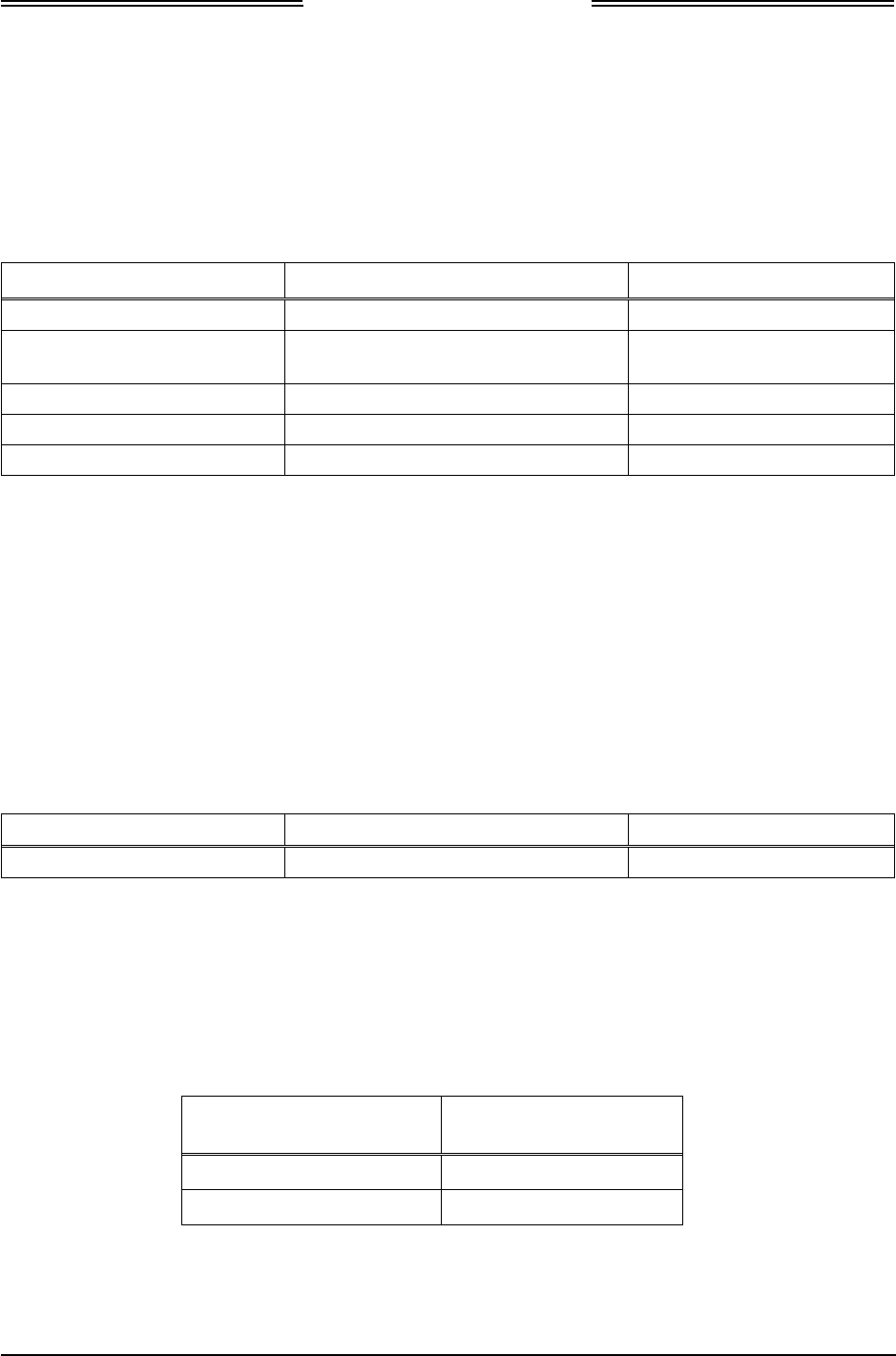
Lynx NGT-9000s
Installation Manual
1.11.4 Traffic Displays
Traffic information is output to a compatible traffic display from the unit using an ARINC 735B interface
format. Possible traffic output format selections include Standard TCAS Intruder File (STIF or TIF) and
Display Traffic Information File (DTIF). The unit allows installed configuration selection of STIF, DTIF,
or both formats of output data via the ARINC 429 bus to the traffic display. Displays not listed below can
still be found to be compatible for installation, but must meet the same specifications.
Table 1-22: Traffic Displays
MANUFACTURER MODEL SW VERSION
Garmin GNS 430W (Standard traffic only) 5.0 GPS SW / Version 5.10
Garmin G 500 (Standard traffic only) GDU-620 Version 6.11
FPGA and I/O Version – 2.1
Garmin GTN 650 (Standard traffic only) (2) 4.0 GPS / SW Version – 5.0
Garmin GMX 200 (Standard traffic only) (1) 2.13
Garmin MX 20 (Standard traffic only) (1) Version – 5.7
Notes:
(1) For Installations using the MX 20 or GMX 200:
• Traffic may be displayed using the ARINC 429 interface (GMX 200 requires optional 429 card)
• The RS-422 interface for traffic is a future option.
(2) Installation using the GTN 650 as an external traffic display should note that the NGT-9000 Pilot-Initiated Self
Test, traffic test pattern is oriented to a heading of zero degrees. (I.e. if the aircraft is pointed a direction other
than True North, the traffic in the test pattern may be rotated relative to the difference between true heading and
0 degrees.)
1.11.5 Weather Display
Table 1-23: FIS-B WX Displays
MANUFACTURER MODEL SW VERSION
Garmin GMX 200 (1) 2.13
Notes:
(1) Traffic must be disabled if using the GMX 200 as a weather display.
1.11.6 WIFI Accessory
The Wifi accessory is also referred to as a “dongle”.
Table 1-24: RS-232 to WiFi Accessories
MANUFACTURER MODEL OR PART
NUMBER
Roving Network RN370M
L-3 Avionics Systems 9080-10024-01
0040-17001-01 General Information Page 1-31
Revision A January 15, 2015

Lynx NGT-9000s
Installation Manual
1.11.7 Personal Electronic Device (PED) Apps
Table 1-25: APPS for PED
MANUFACTURER MODEL
Sky Radar Radenna LLC Sky Radar
Hilton Software LLC Wing X PRO
1.12 SOFTWARE UPDATES
Software for the unit, Lynx MAT, databases (Navigation and Cultural Features) can be obtained by either
downloading from the L-3 Technical Publications website or by receiving a compact disc.
1.12.1 Website Download
Use the following procedure to gain access to the L-3 Technical Publications website.
NOTE
For users of the L-3 RSA tokens a Risk-Based Authentication (RBA)
security system is currently being implemented that will eventually
eliminate the need for physical RSA tokens. Token accounts will not be
immediately converted. Continue to log in using the token until the
month in which it expires. Upon the expiration of the token, the account
will be converted to a RBA account. The expiration date is located on the
back of the RSA token.
First time users of RBA:
1. Go to https://www.l-3avionics.com/customer-support/technical-publications/.
2. On the Technical Publications page first time users must fill out the Secure Site Access Request and
return the form and supporting documentation to L-3 Avionics Systems by fax or email.
3. A User ID and temporary password will be sent by L-3 Avionics Systems after the documentation is
reviewed and accepted.
4. Go to https://www.avionicstechpubs.com.
5. Click on the Self-Service Console Link.
6. Enter the User ID and click the OK button.
7. Enter the temporary password and click the Log On button.
8. Create a new password and press the OK button.
9. Select and answer five security questions. Click the Submit button.
10. The Self-Service Console page is shown. Click the Log Off link in the upper right corner of the page
to complete the process. Go to the User s with site access.
Page 1-32 General Information 0040-17001-01
January 15, 2015 Revision A
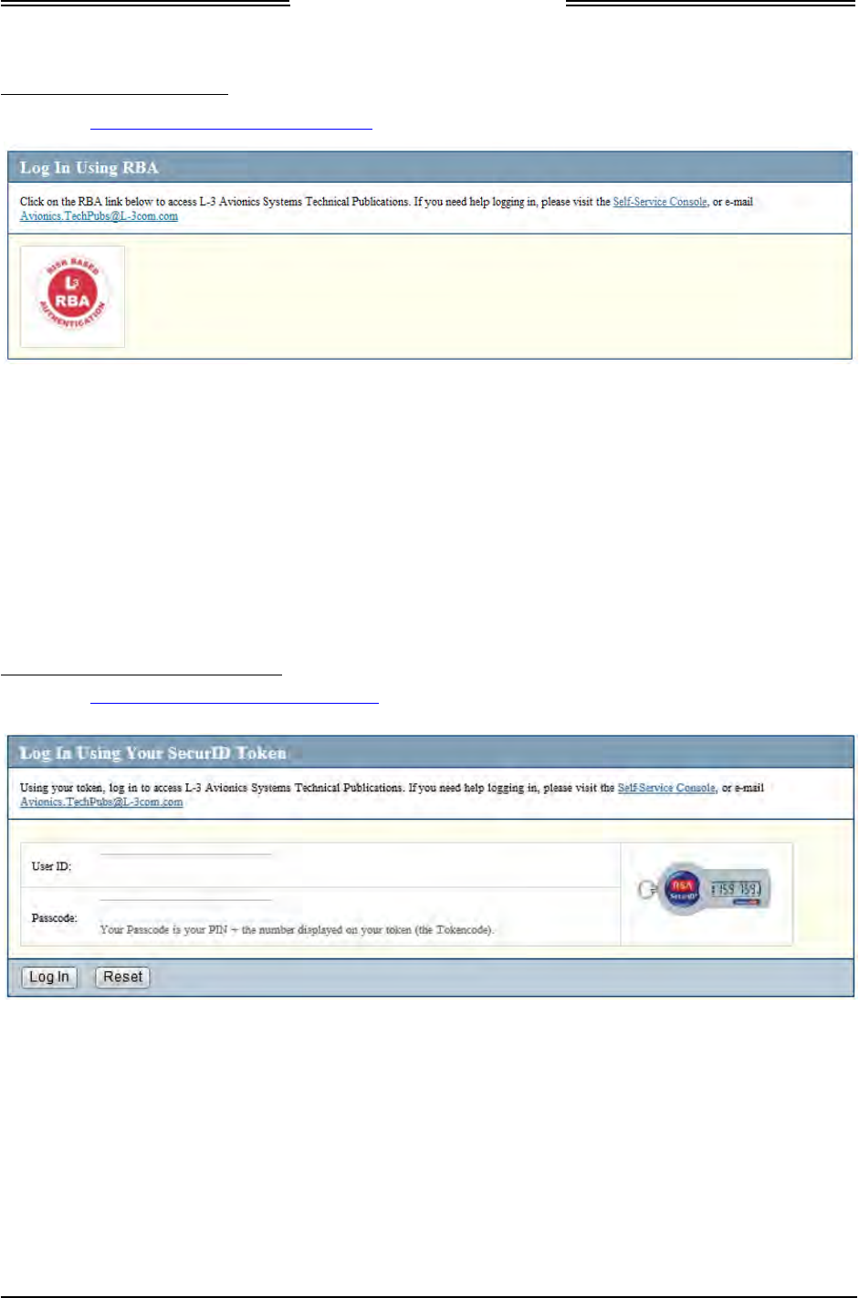
Lynx NGT-9000s
Installation Manual
Users with RBA site access:
1. Go to https://www.avionicstechpubs.com.
2. Using the Log In Using RBA, click on the red L-3 RBA link.
3. Enter User ID and click the OK button.
4. Answer security questions if requested. Click the Continue button.
5. Select the public or shared computer question. Click the Continue button.
6. After successful authentication the license agreement screen is shown. Click the I Agree button to be
taken to the home page.
Users with RSA Token site access:
1. Go to https://www.avionicstechpubs.com/.
2. Using the Log In Using Your SecurID Token, enter the RSA SecureID and Pass code (Pin + Token
code).
3. Read the subscription agreement and select “I Agree”.
0040-17001-01 General Information Page 1-33
Revision A January 15, 2015

Lynx NGT-9000s
Installation Manual
Using the technical publications web site:
1. On the left side of the home page and select Search Documents. Enter “NGT-9000” in the basic
search field.
2. The search results provide a list of available publications and software for the unit.
3. Click on the “details” for the document you want to subscribe too.
4. Click on the “Subscribe to this document”. A zip file will download to your computer. (Note – This
download is only required one time. Afterwards any publication file may be downloaded on its own
from My Subscriptions.)
If you do not see the “Subscribe to this document” option, then access to this document is restricted.
Contact the Manuals Administrator at avionics.techpubs@l-3com.com for subscription access.
Software Revisions and Tools can also be obtained. A software notice document is used to identify
the specific software and has restricted access beyond what is required for the publication. Contact
the Manuals Administrator at avionics.techpubs@l-3com.com for access. The software notices for
the unit are listed in Table 1-26:
Table 1-26: List of Service Notices
SERVICE NOTICE ID DESCRIPTION
8010-17002-0100 Lynx Maintenance Application Tool (Lynx MAT)
Tool used for diagnostics, set up configuration options, and
software downloading.
LynxMMS USB Drivers (versions for Windows 7 & Windows XP)
9020010-001_Rel-1.0 Release 1.0 Composite Software & Boot Loader
8010-22310-0201 68DC Navigational Database – North America
The navigational database expires every 28days; however there
is no requirement to update this because it is used only for
informational purposes.
8010-12004-0001 72DC Cultural Features Database – North American Extended
The 72DC Cultural Features Database contains geographic
boundaries for both states and countries including lakes and
rivers. There is no expiration associated to this database.
Page 1-34 General Information 0040-17001-01
January 15, 2015 Revision A

Lynx NGT-9000s
Installation Manual
1.12.2 Compact Disc
The System Software Compact Disk (CD) contains executable files and instructions to update the unit
software. The contents of the CD are listed in Table 1-27.
The system software is transferred to the unit using a maintenance computer. Refer to the maintenance
section for loading and validation instructions.
Table 1-27: System Software CD Part Numbers and Contents
PART
NUMBER RELEASE CONTENTS
9230-17000-
0100 1.0 1. Software Executable Object Code/Graphics, Data
9020010-001
2. System Software Label Readme,
3. Lynx Maintenance Application Tool, 8010-17002-0100
4. LynxMMS USB Drivers (versions for Windows 7 & Windows XP)
• USB Driver, Windows 7, Lynx MSS, 8010-17004-0100
• USB Driver, Windows XP, Lynx MSS, 8010-17006-0100
0040-17001-01 General Information Page 1-35
Revision A January 15, 2015
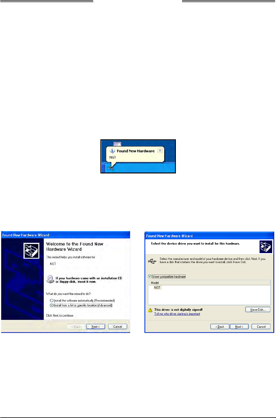
Lynx NGT-9000s
Installation Manual
1.12.3 Installation Procedure for LynxMMS USB Driver
Typically the MPC device manager pops up when the MSS Appliance is connected to the MPC. Follow
the device manager instructions to install the driver. The procedure here is typical, but may differ per
settings on the computer being used.
The following procedures assume the following:
• The MSS Appliance and MPC have power applied.
• The driver has been downloaded from the internet or is available via CD.
• The MSS Appliance is connected to the MPC via USB cable.
1.12.3.1 Windows XP Installation
1. After the MSS Appliance and MPC are connected a “Found New Hardware Wizard” window should
pop up on the MPC.
2. A new hardware wizard dialog is then shown on the MPC.
3. Select “Install from a list or specific location (Advanced)” and Press the “Next” button. See Below.
4. Press the “Have Disk” button.
Page 1-36 General Information 0040-17001-01
January 15, 2015 Revision A

Lynx NGT-9000s
Installation Manual
5. Press the “Browse” button and navigate to the location of the LynxMSS Driver file. See Below.
6. Select the LynxMSS Driver file and press the “Open” button.
7. Press the “OK” button. A screen with “Lynx MSS” as the Model is shown. See Below.
8. Press the “Next” button. The driver installation process begins. See Below.
9. When the installation completes a completed dialog is shown. Press the “Finish” button.
0040-17001-01 General Information Page 1-37
Revision A January 15, 2015
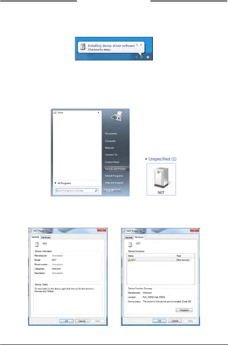
Lynx NGT-9000s
Installation Manual
1.12.3.2 Windows 7 Installation
1. After the MSS Appliance and MPC are connected, an “Installing device driver software” is shown
on the tray.
2. If the Driver Software Installation fails a dialog window is shown. Close out of that window.
3. Open the Devices and Printers from the Start menu. An “unspecified” device with the label “NGT”
should be available. See below.
4. Double click on the “unspecified” device icon.
5. In the NGT Properties window select the “Hardware” tab. See below.
6. Select the “Properties” button.
Page 1-38 General Information 0040-17001-01
January 15, 2015 Revision A
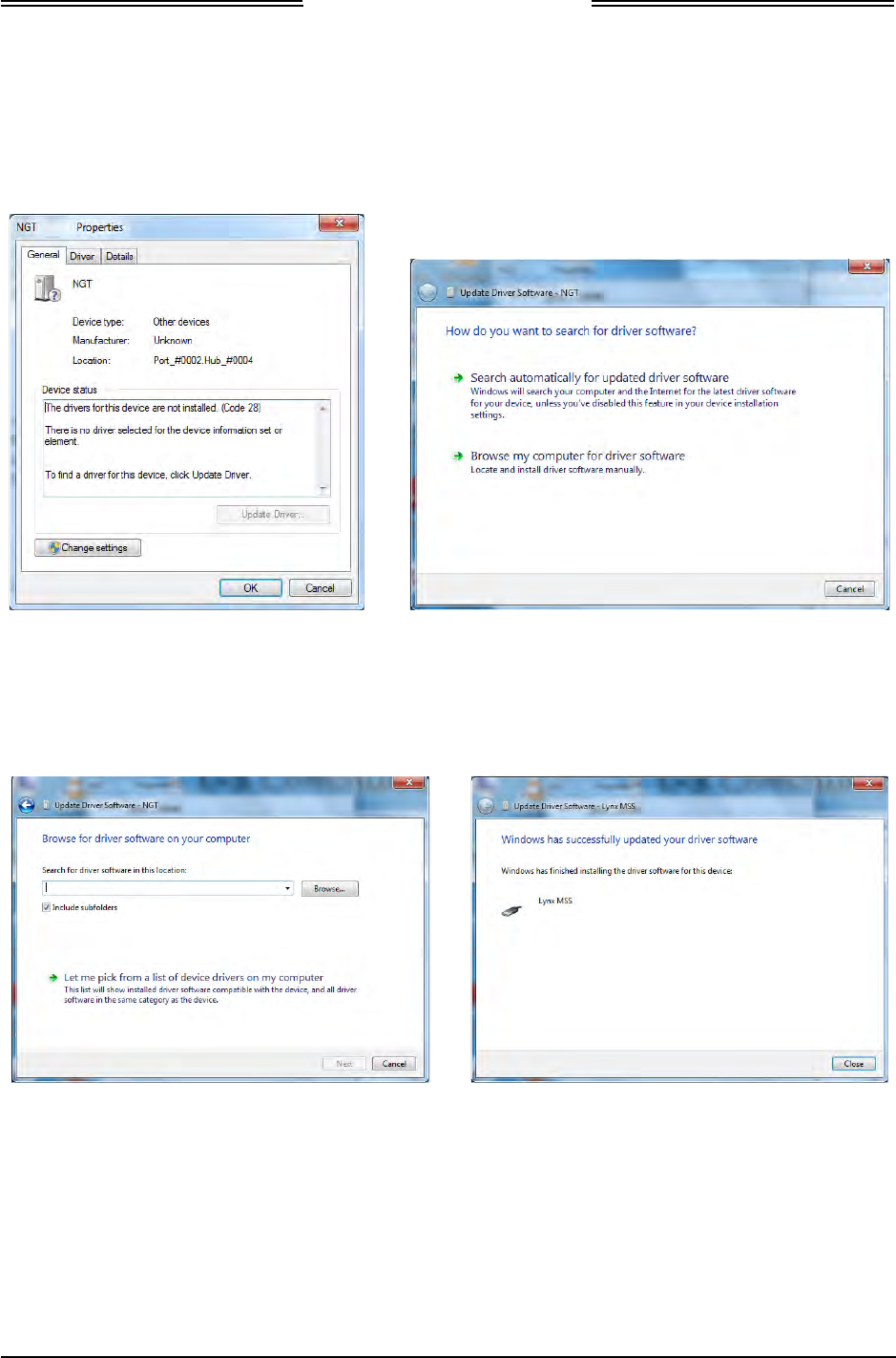
Lynx NGT-9000s
Installation Manual
7. Select the “Change Settings” button. See below.
8. Select the “Update Driver” button.
9. Select the “Browse my computer for driver software”.
10. Browse to the Windows 7 USB Driver folder and select “Open”. See below.
11. Select “Next”. The driver installation process begins.
12. When the installation completes a completed dialog is shown. Press the “Close” button.
0040-17001-01 General Information Page 1-39
Revision A January 15, 2015

Lynx NGT-9000s
Installation Manual
1.13 INSTALLATION APPROVAL AND LIMITATIONS
1. This article meets the minimum performance and quality control standards required by the applicable
technical standard orders (TSOs). Those installing this article, on or in a specific type or class of
aircraft, must determine that the aircraft installation conditions are within the applicable TSOs
standards. TSO articles must have separate approval for installation in an aircraft. The article may be
installed only according to 14 CFR parts 43 or the applicable airworthiness requirements.
2. All antennas used in the installation must meet the requirements specified in this manual.
3. The GPS receiver must use antenna meeting the requirements specified in this manual.
4. The use of a frequency diplexer is not supported and as such the L-Band antenna cannot be diplexed
with another L band antenna.
5. It is the installer’s responsibility to ensure the ADS-B Out system is compliant with AC 20-165A, 14
CFR 91.225 (b) and 91.227 when installed in accordance with L-3’s installation instructions.
6. If aircraft ground speed is less than 7 knots, and there is not a valid heading input into the unit, then
TAS traffic data only may be displayed. No traffic is displayed if TAS is in standby.
7. The Lynx NGT-9000s is not approved for installations with SATCOM-equipped airplanes.
8. The Lynx NGT-9000 may be optionally configured to support the TAS function or the Diversity
function, but both options may not be selected at the same time and is not supported by the FAA
TSO Approval.
Page 1-40 General Information 0040-17001-01
January 15, 2015 Revision A

Lynx NGT-9000s
Installation Manual
Section
2
Installation
2.1 INTRODUCTION
This section describes the installation of the Lynx Multilink Surveillance System (MSS). Installation must
be made by qualified personnel, in conformance with applicable government regulations. The information
furnished is for convenience only.
Tolerances (unless otherwise indicated):
ANGLES ARE ± 0.5°
0.00 TWO PLACE DECIMALS ARE ± 0.02
0.000 THREE PLACE DECIMALS ARE ± 0.010
2.2 UNPACKING AND INSPECTING
Carefully unpack the unit and note any damage to shipping containers or equipment. Visually inspect
each component for evidence of damage. Compare the equipment received with that noted on the packing
list. Report immediately any missing items or evidence of damage to the carrier making the delivery. To
justify a claim, retain the original shipping container and all packing materials.
Every effort should be made to retain the original shipping containers for storage. If the original
containers are not available, a separate cardboard container should be prepared that is large enough to
accommodate sufficient packing material to prevent movement.
2.2.1 Transport and Storage Considerations
Transport of the avionics equipment should be done in accordance with standard procedures, i.e. hand
carried or transported in the original container. The container limits the shock to the indicator at a
maximum of 20g’s when dropped from a distance of 36 inches.
Storage of avionics equipment must be consistent with industry standards for avionics equipment and
performs satisfactorily after periods of storage up to 24 months. The ambient temperature of the storage
area should not fall below -55° C (-65° F) or rise above +85° C (+185° F).
0040-17001-01 Installation Page 2-1
Revision A January 15, 2015

Lynx NGT-9000s
Installation Manual
2.3 INSTALLATION PROCEDURES
1. The installer must take the following into consideration prior to installation. Specific procedures for
installation of the Lynx NGT-9000s, Data Configuration Module, Mounting Rack, and Directional
Antenna (for TAS option) are detailed in their respective paragraphs below.
• The installer must obtain installation approval (i.e. Supplemental Type Certification).
• Follow the acceptable avionics installation practices in FAA Advisory Circulars AC 43.13-1B
and AC 43.13-2B or later revision of these documents.
• It is the responsibility of the equipment installer to determine that the required aircraft viewing
envelope is within the specified display viewing envelope(s). Refer to paragraph 2.3.1.
• Bonding impedance between aircraft ground and the unit chassis must be less than 2.5
milliohms.
• It is recommended that the aircraft battery be disconnected before performing installation
procedure.
• Installers are responsible for obtaining installation hardware (i.e. screws, supporting plates, etc)
beyond those parts that come with the installation kits.
• It is recommended that one of the following Installation Kits be used for the installation of the
unit. Refer to the General Information section for details.
o Rack Assembly with Straight Coax Connector P/N 9060-17000-01
o Rack Assembly with Right Angle Coax Connector P/N 9060-17000-02
• All antenna cables should be clearly marked to prevent inadvertent installation into the wrong
connector position.
• Tighten all screws to snug (i.e. only such torque that can be applied by hand) unless specific
torque instructions are given.
• After installation, refer to the Installation Checkout section for calibration, calibration, power-
up and ground testing procedures.
2. Electrical equipment chassis, shield/ground terminations, antennas, supporting brackets, and racks
must be electrically bonded to the aircraft's main structure (metallic aircraft) or instrument panel
(composite aircraft). Compliance of the electrical bonding should be verified by inspection using a
calibrated milliohm meter. An equivalent OEM procedure may also be substituted.
• The electrical bond should achieve direct current (DC) resistance less than or equal to 2.5
milliohms to structure local to where the equipment is mounted for metallic aircraft or tube and
fabric aircraft.
• The electrical bond should achieve direct current (DC) resistance less than or equal to 5.0
milliohms to the instrument panel for composite aircraft.
The antenna ground plane must be electrically bonded to the antenna baseplate. Do not remove paint
on outer skin of aircraft under the footprint of the antenna baseplate unless necessary to meet
bonding requirements. Refer to antenna manufacturer's installation instructions.
Page 2-2 Installation 0040-17001-01
January 15, 2015 Revision A

Lynx NGT-9000s
Installation Manual
2.3.1 Location
The unit is mounted in the instrument panel where the touch screen display can be used to view aircraft
flight information and provide operational control.
1. The unit should be accessible for inspection, maintenance, or removal, and free from instrument
panel structural flexure and excessive vibration or heat.
2. The wiring and antenna cables should not run adjacent to heaters, engine exhaust, or heat sources.
3. The display viewing envelope has a viewing angle of at least ±45° in the horizontal plane and at least -
10º to +30º in the vertical plane as seen from an eye position of 30 inches from the front of the display.
4. The unit should be located in an area where the touch screen control is within easy reach of the pilot
and cannot be obstructed from continuous view (i.e. behind a control yoke).
5. A Mounting Rack is required to install the panel mount NGT-9000. Two installation kits are
available each with their own mounting rack. See details below:
• Mounting Rack Assembly with Straight RF Connector P/N 9060-17000-01
• Mounting Rack Assembly with Right Angle RF Connector P/N 9060-17000-02
Ordering information for the installation kits are found in the General Information section.
6. Compare the space requirements of the Mounting Rack with the installation area being considered.
The outline drawing for the unit is located in Figure 2-1. The outline drawing of the Rack Assembly
is located in Figure 2-2. The installer is advised to consider the space requirements (2-3 inches)
needed for the connector backshell and the cable bend radius.
0040-17001-01 Installation Page 2-3
Revision A January 15, 2015
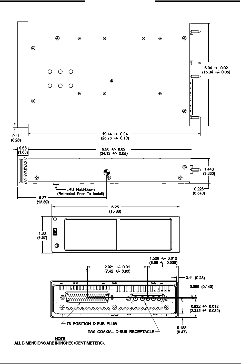
Lynx NGT-9000s
Installation Manual
Figure 2-1: Outline Dimensions for Panel Mount NGT-9000
Page 2-4 Installation 0040-17001-01
January 15, 2015 Revision A
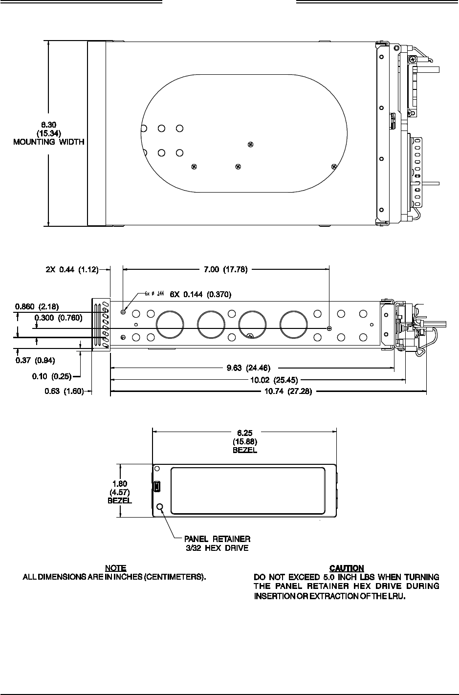
Lynx NGT-9000s
Installation Manual
Figure 2-2: Outline Dimensions for Mounting Rack
0040-17001-01 Installation Page 2-5
Revision A January 15, 2015

Lynx NGT-9000s
Installation Manual
2.3.2 Electrical Connections
1. The installer must take the following into consideration before installation.
• Use of any wire or cable not meeting specification voids all warranties.
• The installer is responsible for supplying wires, cables and connectors.
• Wire-marking identification is at the discretion of the installer.
• All wiring must be in accordance with industry-accepted methods, techniques, and practices.
• The assembly guidelines for the antenna cables are detailed in paragraph 2.3.2.3.
• Refer to Appendix A for signal name and cable characteristics prior to wiring installation.
• The length and routing of the external cables must be carefully studied and planned before
attempting installation of the equipment.
• The wiring harness should not run adjacent to heaters, engine exhaust, and heat sources or be
located near fuel lines, high electrical capacity lines, flight control cables, and protected areas of
the aircraft or be exposed to wire chafing.
• Avoid sharp bends while routing the cables.
• Keep the cables run as short as possible. Grounding pigtails (if installed) should not exceed
more than 3 inches in length. Terminate shields in the backshell of the mating connector (at P1).
• The unit should be placed on its own separate circuit breaker.
• Required connectors and contact pins are supplied in the installation kits (paragraph 1.7).
• All wires should be 22 AWG or 24 AWG as noted in the interconnect diagram. Use M22759 or
equivalent wire and Tefzel Wire M27500 or equivalent for twisted shielded wired for installation.
• Cable specifications and approved vendors are provided in Equipment Required Not Supplied.
o The L-Band and GPS Cables must be RG-400 or equivalent. Refer to paragraph 2.3.2.3 for
location and fabrication information. Cable attenuation must not exceed 1.5 dB (including
the connectors).
o The Directional Cables (required only for models with TAS) requires three cable
assemblies; sum (Sigma Port – blue band), bit probe (Probe Port) and difference (Delta Port
– red band). Cable attenuation for the sum and difference ports must not exceed 1.5 dB.
• The DCM is permanently attached to the mating connector during wire installation and must be
covered by the tinned copper braided shield. Outline dimensions for the configuration module
are shown in Figure 2-6.
2. Refer to Figure 2-3 (sheet 1 thru 3) for Interconnect Wiring Diagram. Interconnect diagrams for
alternate equipment is provided when available. Refer to Appendix A for option equipment wiring
diagrams.
3. Refer to Figure 2-4 for pin locations, signal names, and function. Connector information for P1 is
supplied in the recommended installation kit. The assembly requirements for the P1 mating
connector are shown in Figure 2-5.
4. The GPS and L-band (UAT) connections (TNC Amphenol P/N 31-5660) require a male TNC mating
connector.
Page 2-6 Installation 0040-17001-01
January 15, 2015 Revision A
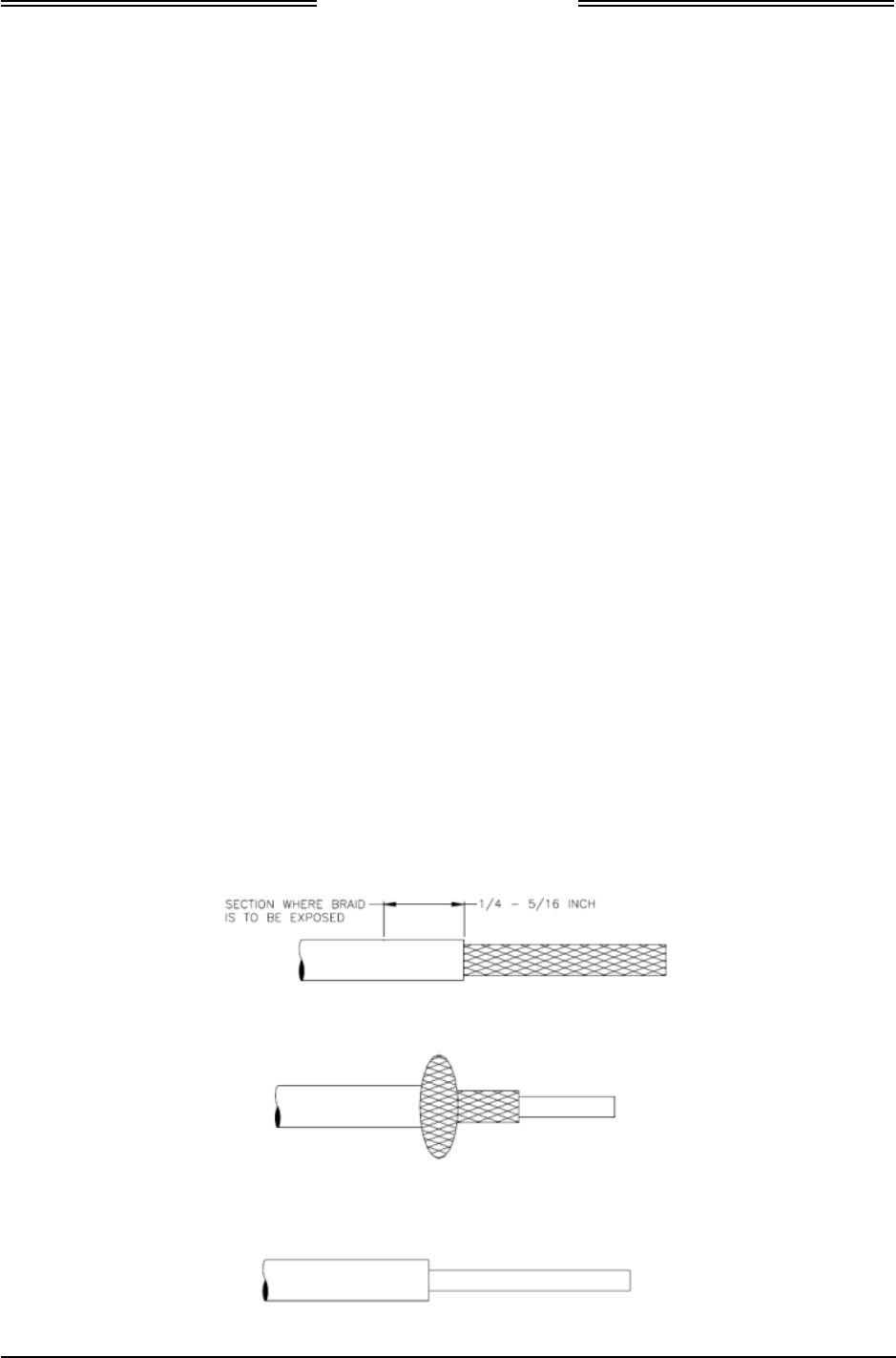
Lynx NGT-9000s
Installation Manual
5. The WiFi interface must be configured using the MPC MAT WiFi interface prior to installation.
Refer to the Installation Checkout section (para. 3.3) for details.
6. When installing fail lamps in the cockpit, then amber colored lamps are required. Lamp power
should be connected to dimming bus or day/night switch. Label lamps as “Traffic Alert” (amber
lamp), “ADS-B Fail” (amber lamp), and “TIS-B No Coverage” (blue lamp) as applicable.
7. It is recommended that the installer perform the following wiring checks during installation:
• Check all wiring point-to-point for continuity before connecting components.
• Ensure voltages are not applied to signal wires.
• Inspect cables for correct connection.
8. Use the following information for interfacing compatible equipment. Additional information may be
found in the General Information section under Equipment Interfaces.
• Installations using the GMX 200 connect the Lynx NGT-9000s (TX pins 52 & 53) only.
2.3.2.1 Shielded Cable Preparation
• Use these instructions to prepare the Shielded Tefzel Wire (MIL27500) or equivalent for connection
to the 62 pin sub D connector.
• The crimp pins of the 62 pin connector are to be crimped to the wires.
• The Outer Jacket of the cable is to be removed for all cables on which the solder sleeve to be placed
for ground contact. The installer is to ensure that the outer jacket is removed on the cable for the
length of the cable inside the 62 pin connector backshell and can be around 1 to 1.5 inches from the
crimped pin side. Refer to Table 2-1 for the procedure on how to remove the jacket and insertion of
solder sleeve.
1. The cable can be stripped according to the following procedure designed to leave the shield braid
smooth and flat. The use of finger cots is recommended to prevent transfer of oils to the shield.
a. Score and remove the jacket as shown below:
b. Bunch the braid:
c. Trim the braid as close as possible to the jacket:
0040-17001-01 Installation Page 2-7
Revision A January 15, 2015
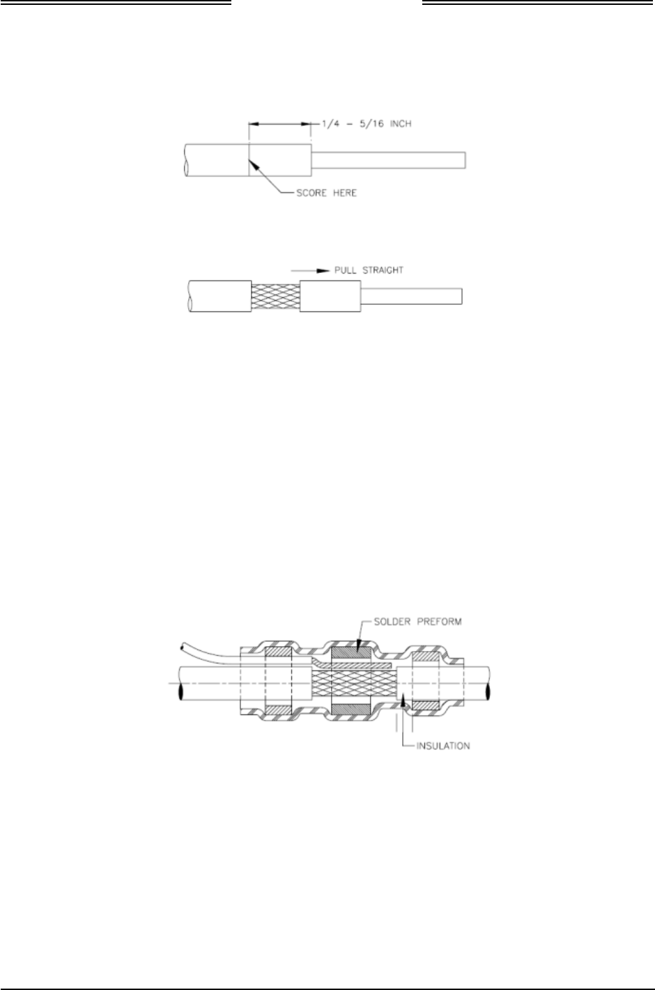
Lynx NGT-9000s
Installation Manual
d. Score the jacket ¼ to 5/16 inch from the end of the braid:
e. Remove the section of jacket carefully by pulling straight. This will flatten the braid strand ends:
f. Inspect the cable to make sure that the braid strands are lying against the primary insulation.
2. Solder Sleeve placement
NOTE
Ensure the strands of the shield braid and ground lead lay flat and smooth.
a. Position the stripped portion of ground lead (s) against the stripped portion of the shield braid.
b. Slip the selected shield terminator over the cable and ground lead assembly. Rotate the shield
terminator as it slides over the ground lead to prevent it from catching on the strands.
c. Position the terminator so that the exposed shield is centered between the solder sleeve (solder
preform) inserts and some of the cable jacket is visible between the solder sleeve inserts and the
exposed shield.
Page 2-8 Installation 0040-17001-01
January 15, 2015 Revision A

Lynx NGT-9000s
Installation Manual
3. Apply Heating on the Solder Sleeve
a. Use Tyco Electronics approved heat source and reflector as shown below:
Heat Gun / Setting Reflector
HL1910E = 6 on dial
HL2010E = 700°F on LCD
PR-25 or PR-25D and
HL1802E-ADAPT
b. Allow hot air heaters to warm up before using.
c. Position the assembly (cable, ground lead and terminator) in the reflector so that the solder
preform is in the center of the hot air or at the focal point on the infrared heaters.
d. If the cable jacket or ground lead insulation is susceptible to heat damage for example, if the
insulation is PVC (PVC may not be used on new installations), or if the infrared heating is used
with black insulation, move the assembly toward the heat source to minimize unwanted
exposure of the jacket to the heat.
e. Heat until the solder preform melts flows and wets the shield and ground lead.
f. Some terminators contain a thermal indicator to signal when the correct amount of heat has been
applied to the solder. There are two types of indicators. One is a thermo-chromic material which
signals correct heating by loss of color. Terminators with this type of indicator should be heated
until all the colored material in the joint area has turned colorless. (Slight traces of the material
may remain in the standing of the shield). The other type of thermal indicator is a ring of fusible
material around solder preform. Terminators with this Bi-Alloy indicator should be heated until
the solder preform melts and the indicator ring completely disappears in the joint area.
0040-17001-01 Installation Page 2-9
Revision A January 15, 2015
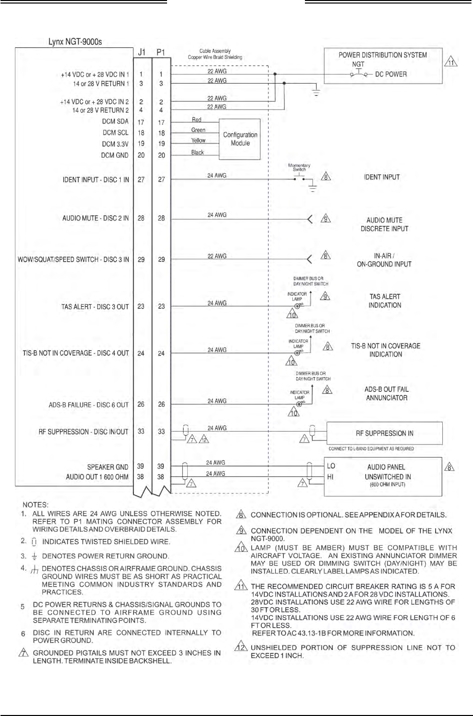
Lynx NGT-9000s
Installation Manual
Figure 2-3: Interconnect Wiring Diagram
(Sheet 1 of 3)
Page 2-10 Installation 0040-17001-01
January 15, 2015 Revision A
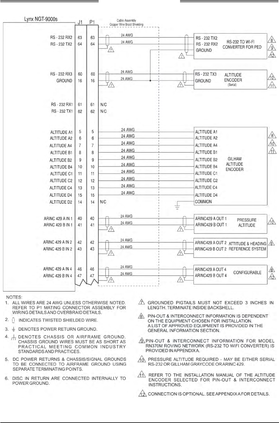
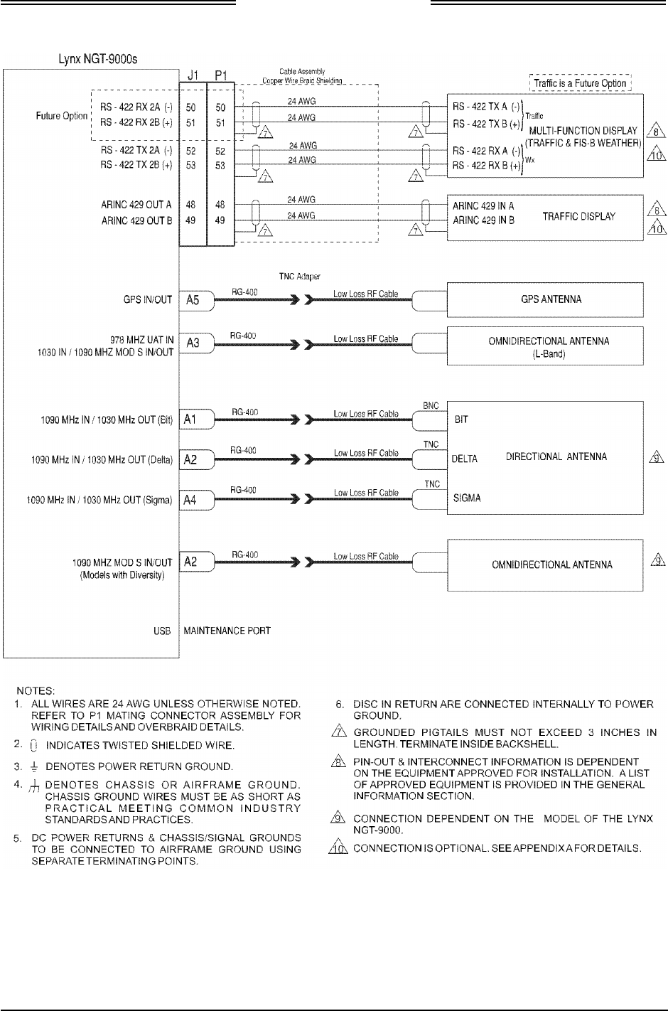
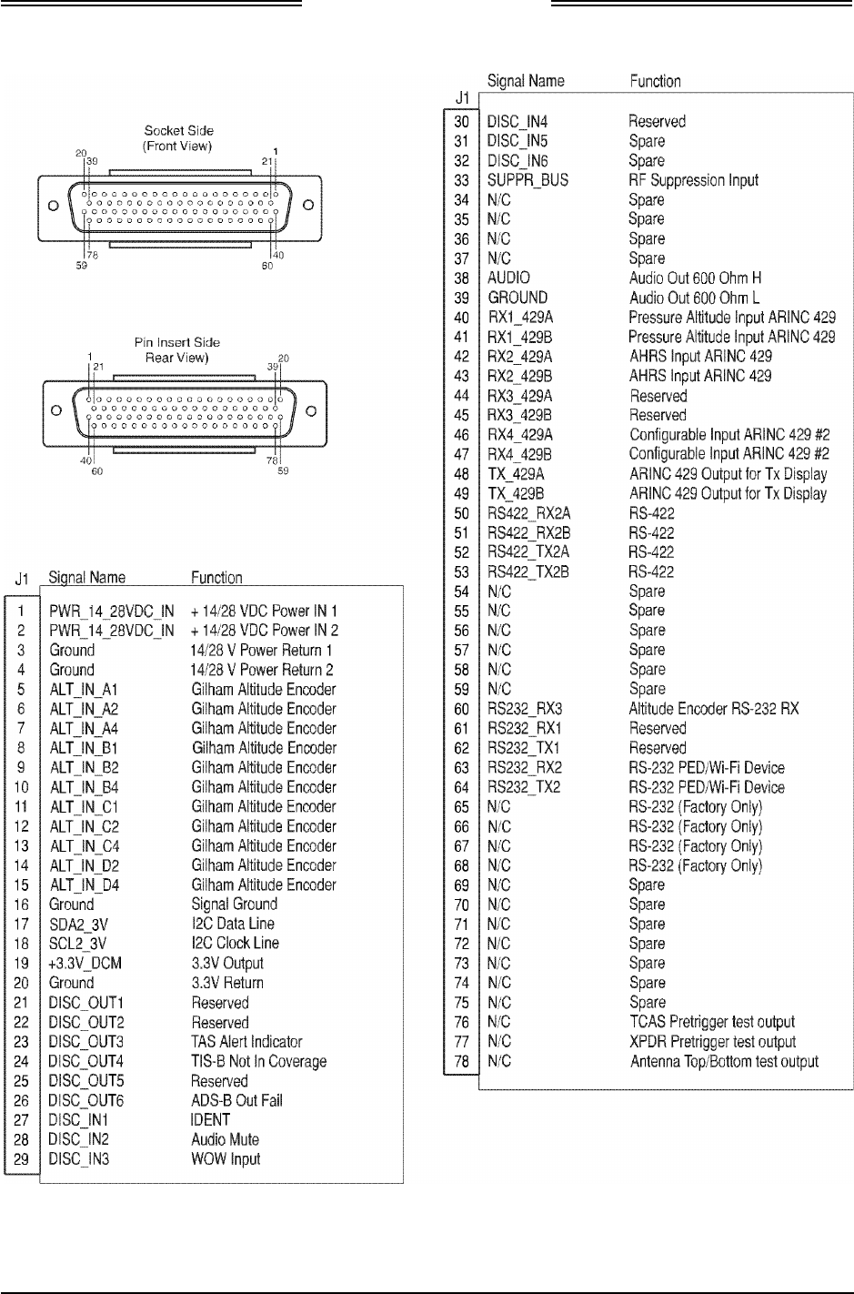
Lynx NGT-9000s
Installation Manual
Figure 2-4: Mating Connector (P1) and Pin Assignments
0040-17001-01 Installation Page 2-13
Revision A January 15, 2015
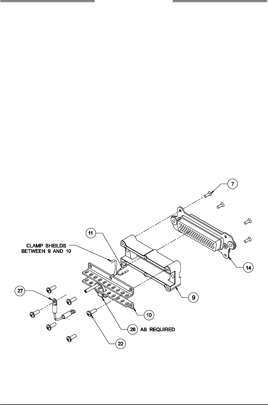
Lynx NGT-9000s
Installation Manual
2.3.2.2 P1 Mating Connector Assembly
Installer must take into consideration the length of the wiring harness to insure an adequate service loop
before installing the unit. Refer to Figure 2-5.
1. Assemble Connector Pins P/N M39029/57-354 (item 11) to wires using Crimp Tool M22520/5-01
and Insert M22520/5-05.
2. Secure Backshell P/N 9010-17012-01 (item 9) to P1 Mating Connector P/N 9080-17006-01 (item
14) using 4 Screws P/N 2000-10085-01 (item 7).
3. Secure 2 Wire Clamps P/N 9000-17076-01 (item 10) and 1 Cable Ground Strap P/N 9020-17002-01
(item 27) to Backshell (item 9) using 6 Screws P/N 2000-10087-01 (item 22). (Refer to Figure 2-12
for the installation location of the other side of the cable ground strap.)
4. Insert Wires to P1 Mating Connector.
5. Secure Wires to Wire Clamps (item 10) using Cable Ties P/N 1040-10002-01 (item 26) as required.
6. Refer to Figure 2-6. The Configuration Module needs to be installed outside the Backshell (item 9)
and Wire Clamp (item 10) and covered by an overbraid (AA59569R36TXXXX, the XXXX refers to
the diameter of the braid. Secure the exposed sides of the overbraid with tie wraps.
7. A 9 Pin Sub-D Connector P/N M24308/2-1 or equivalent is required for installations intending to use
the WiFi interface. Connect WiFi Accessory
Figure 2-5: P1 Mating Connector Assembly
Page 2-14 Installation 0040-17001-01
January 15, 2015 Revision A
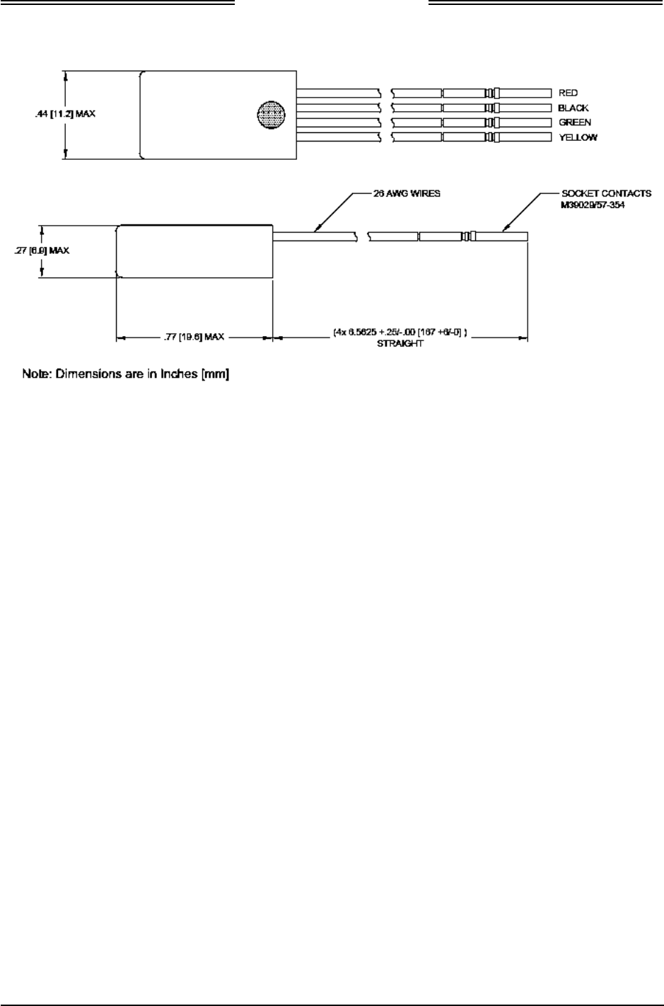
Lynx NGT-9000s
Installation Manual
Figure 2-6: Outline Dimensions for the Data Configuration Module (9230-17003-01)
0040-17001-01 Installation Page 2-15
Revision A January 15, 2015
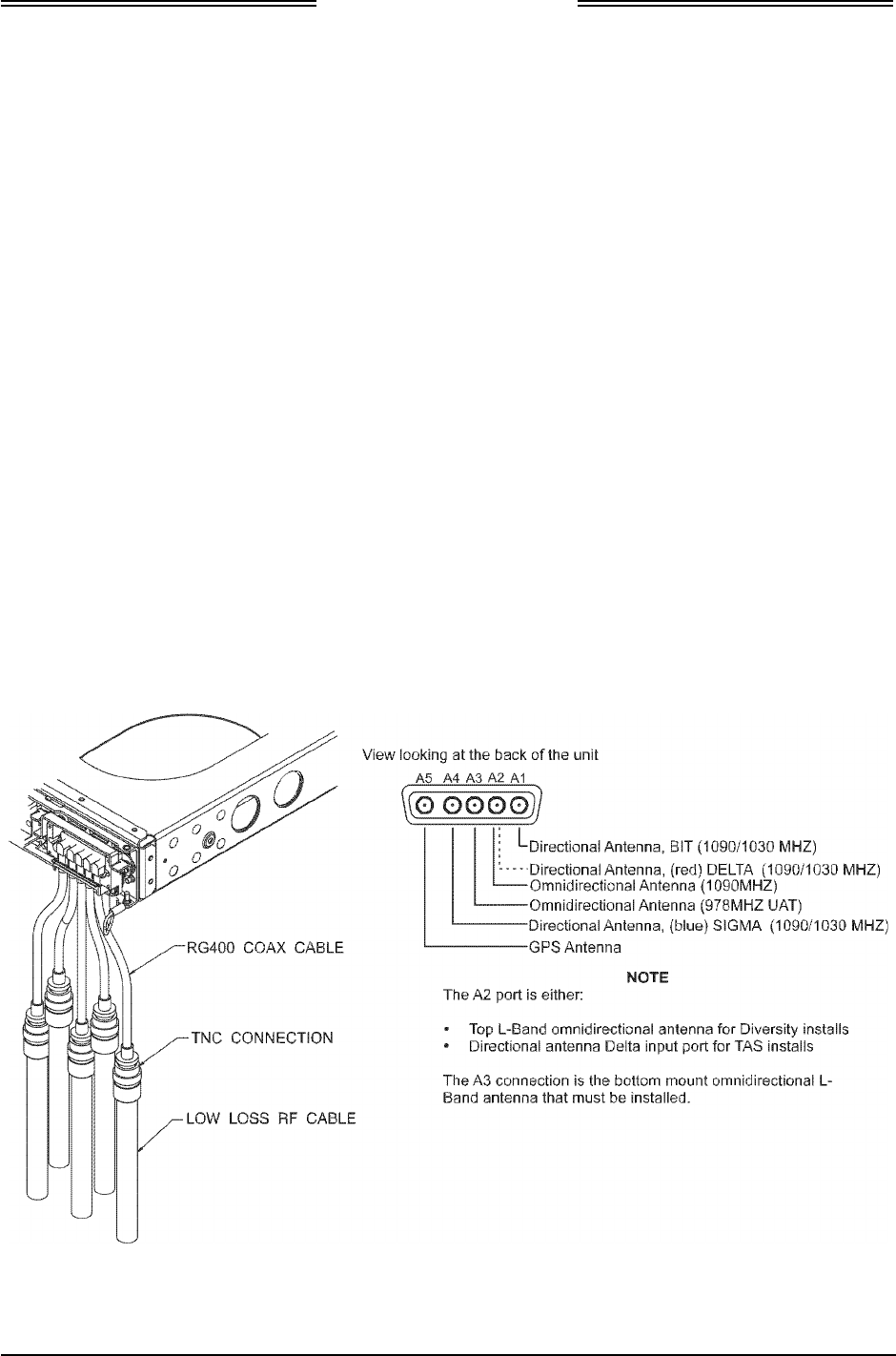
Lynx NGT-9000s
Installation Manual
2.3.2.3 Antenna Cable Assembly
The instructions below provide the information necessary to assemble the contacts required to connect the
coaxial cable to the unit. The other end of the cables typically has TNC Adapters installed that connect to
low loss RF cables. See Figure 2-7.
All models of the Lynx NGT-9000s are required to have GPS and Omnidirectional (UAT) cable
connections (A5 & A4). Models with TAS have three cables connecting to A1, A2, and A4. Models with
Diversity have one cable connecting to A2.
NOTES
1. The cable attenuation and VSWR ratings must be verified to not
exceed the specified values.
2. Place 4-6 inches (10.2 to 15.2 cm) of heat shrink tubing over each
antenna connector and cable to add strain relief and alleviate stress
caused by aircraft vibration.
When routing antenna cables, observe the following precautions:
• All cable routing should be kept as short (do not exceed maximum cable length detailed in the
vendor tables, paragraph 1.6, in the General Information section) and direct as possible.
• Avoid sharp bends (do not exceed maximum bend radius detailed in the vendor tables in the General
Information section, paragraph 1.6.
• Avoid routing cable near power sources (e.g., 400 Hz generators, trim motors, etc.) and near power
for fluorescent lighting.
• Avoid routing cable near ADF antenna cable (allow at least a 12-inch (30.5) separation).
Figure 2-7: Example of Assembled RF Cable
Page 2-16 Installation 0040-17001-01
January 15, 2015 Revision A
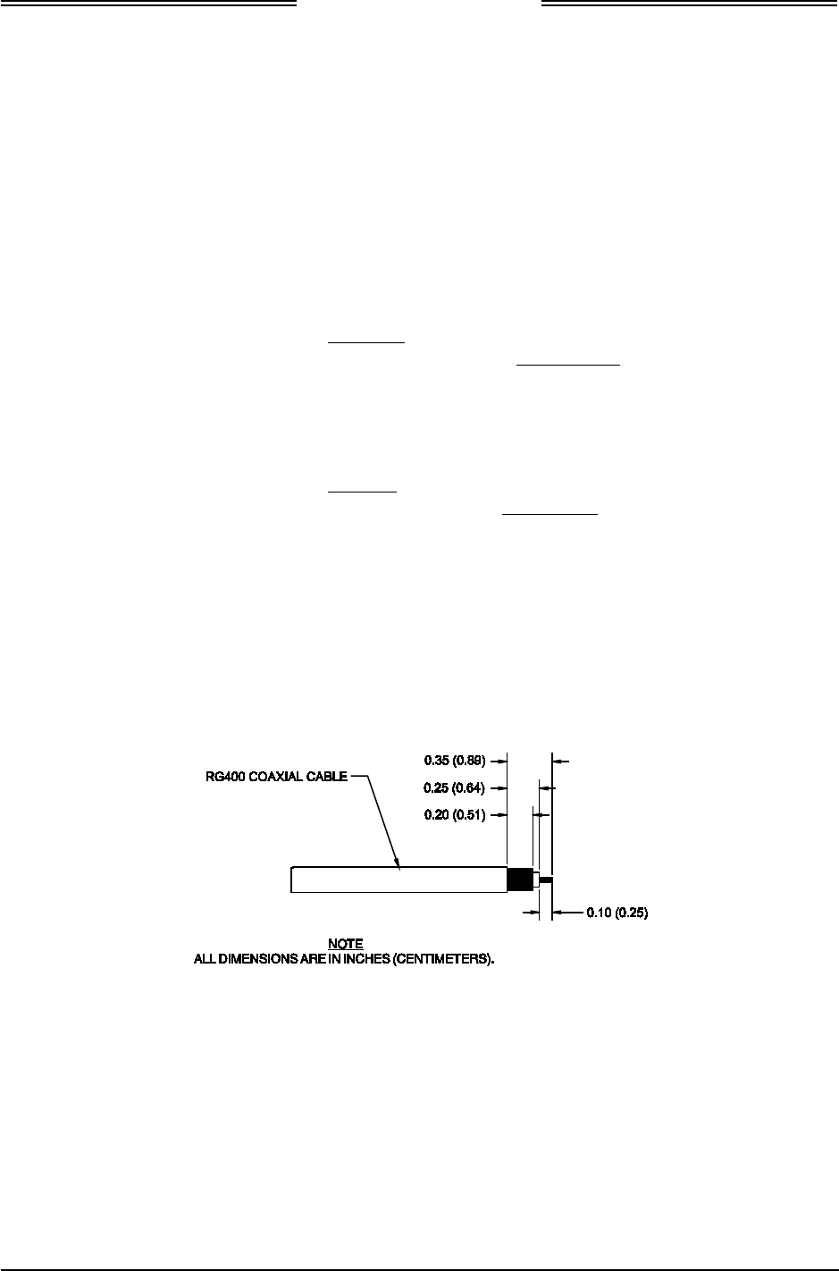
Lynx NGT-9000s
Installation Manual
2.3.2.3.1 Directional Antenna Cables
The directional antenna installation is optional and used only for models with Traffic Alert System (TAS).
1. The directional antenna requires three cable assemblies; sum (Sigma Port), bit probe (Probe Port)
and difference (Delta Port). Cable attenuation for the sum and difference ports must not exceed 1.5
dB. Attenuation for the bit probe cable must not exceed 6 dB. VSWR, on cables attached to the sum,
bit probe, and difference ports, must not exceed 1.5:1. (See paragraph 1.6 for antenna cable vendors
and specifications.)
2. At the antenna, each connector has an identifying color band. To ensure the cables are connected to
the correct port, affix the following marking at the termination points of each cable:
• Sum (Sigma) Port The Sum (Sigma) port is the forward antenna connector. It is marked
with a blue band. Fabricate the sum antenna cable with a TNC
connector at each end. Affix a blue marking band on each connector.
At the NGT-9000, the sum port (A4) is identified with blue marking.
• Bit Probe Port The Bit Probe port (A1) is the center antenna connector. Fabricate the
probe cable with a BNC connector at each end.
• Difference (Delta) Port The Difference (Delta) port is the rear antenna connector. It is marked
with a red band. Fabricate the difference antenna cable with a TNC
connector at each end. Affix red marking band on each connector. At
the NGT-9000, the difference port (A2) is identified with red marking.
2.3.2.3.2 Coax Cable Assembly Guidelines
The cable manufacture’s cable prep specifications take precedence over the guidance provided in this
manual. Use the following procedures to assembly straight or right angle coax connectors.
1. Cut back outer plastic sheath and inner insulator to expose the copper shield and copper core as
shown in Figure 2-8.
2. Slide Crimp Contact over coaxial cable.
Figure 2-8: Coax Cable Preparation
0040-17001-01 Installation Page 2-17
Revision A January 15, 2015
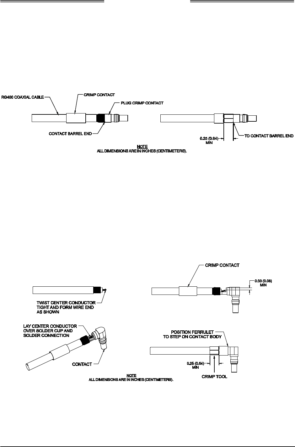
Lynx NGT-9000s
Installation Manual
2.3.2.3.3 Straight Coax Contact Assembly
Refer to Figure 2-9 for the following instructions.
1. Slide Plug Crimp Contact (item 23 of install kit) over inner insulator. The copper shield must be over
the Contact sleeve.
2. Slide Crimp Contact to contact barrel end of Plug Crimp Contact.
3. Use Crimp Hand Tool P/N M22520/5-01 and Insert P/N M22520/5-05 to crimp Contact.
Figure 2-9: Straight Coax Contact Shield Termination
2.3.2.3.4 Right Angle Coax Contact Assembly
Refer to Figure 2-10 for the following instructions.
1. Twist center conductor tight and bend wire end slight upwards.
2. Slide Contact over inner insulator. The copper shield must be over the Contact sleeve and the coax
center conductor must be inside the connector solder cup. Solder the center conductor to the contact.
3. Slide Crimp Contact (item 18 of install kit) over the step on contact body.
4. Use Crimp Hand Tool P/N M22520/5-01 and Insert P/N M22520/5-05 to crimp Contact. The
crimped area must be on the side furthest from the connector (over the cable).
Figure 2-10: Right Angle Coax Contact Installation
Page 2-18 Installation 0040-17001-01
January 15, 2015 Revision A
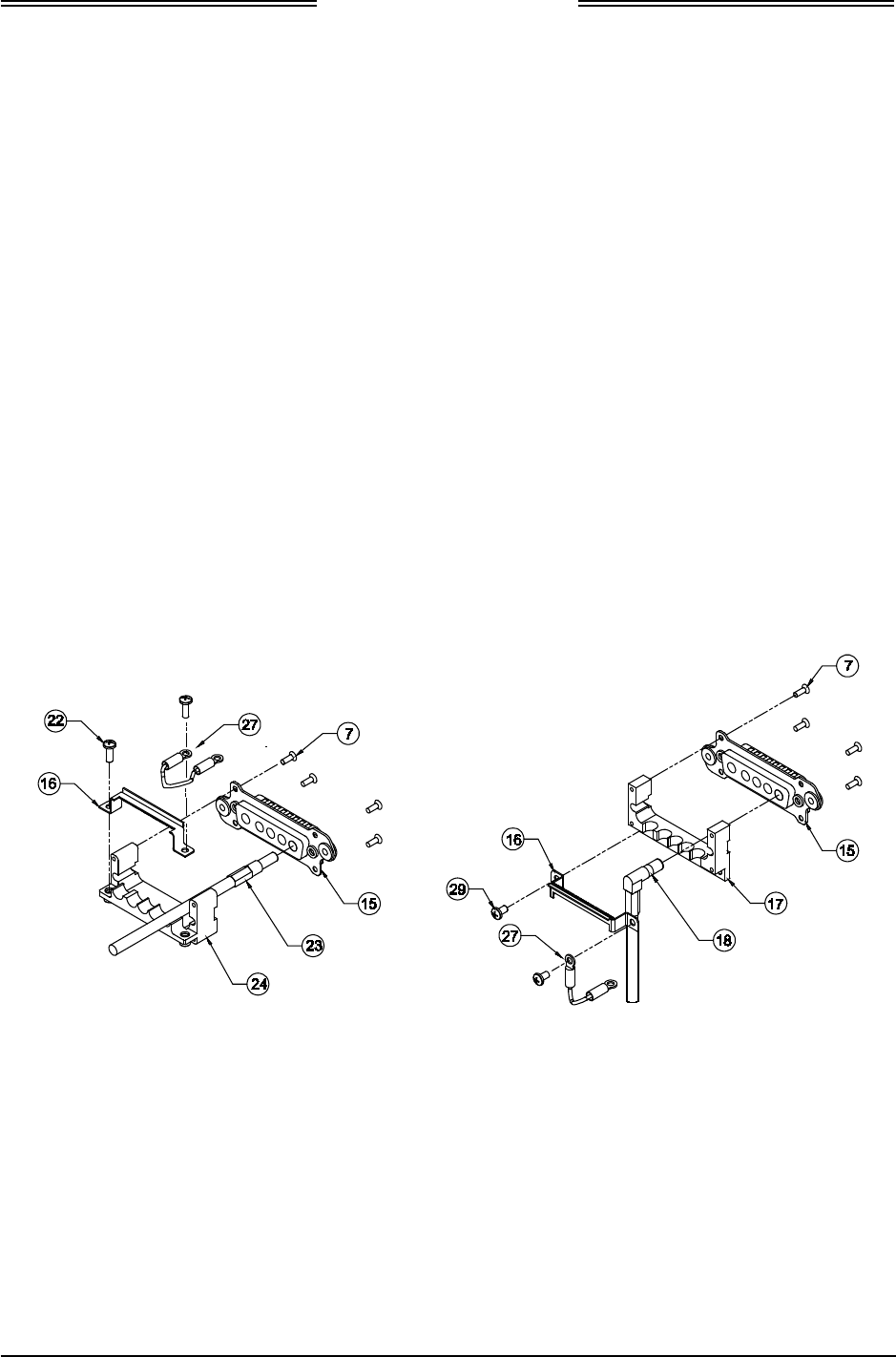
Lynx NGT-9000s
Installation Manual
2.3.2.4 Coax Connector Assembly
The number of antenna cables required for installation is based on the model of Lynx NGT-9000s. The
basic model has a GPS and omnidirectional (bottom mounted L-Band) antenna connection. Models with
Diversity only have a secondary top mounted L-Band antenna connection. Models with TAS have three
directional antenna connections.
2.3.2.4.1 Straight Coax Connector
1. Refer to Figure 2-11.
2. Secure Backshell P/N 9000-17106-01 (item 24) to Connector P/N 9080-17007-01 (item 15) using 4
Screws P/N 2000-10085-01 (item 7).
3. Insert Cables into the appropriate slots of Connector P/N 9080-17007-01 (item 15).
4. Secure 1 Spring Clip P/N 90001963-001 (item 16) and 1 Cable Ground Strap P/N 9020-17002-01
(item 27) to Backshell P/N 9000-17106-01 (item 24) using 2 Screws P/N 2000-10087-01 (item 22).
2.3.2.4.2 Right Angle Coax Connector
1. Refer to Figure 2-11.
2. Secure Backshell P/N 9000-17105-01 (item 17) to Connector P/N 9080-17007-01 (item 15) using 4
screws P/N 2000-10085-01 (item 7).
3. Insert Cables into the appropriate slots of Connector (item 15).
4. Secure 1 Spring Clip P/N 90001963-001 (item 16) and 1 Cable Ground Strap P/N 9020-17002-01
(item 27) to Backshell (item 17) using 2 Screws P/N 101-10114-011 (item 29).
Straight Connector Right Angle Connector
Figure 2-11: Connector Assembly
2.3.3 Panel Installation
This procedure assumes that the mating connector and Antenna Cables are assembled. Refer to Figure 2-12.
1. Secure P1 Mating Connector to Rear Plate P/N 9000-17025-02 (item 2) using Nut Plate P/N 9000-
17034-01 (item 6) and 2 Screws P/N NAS514-P-440-7 (item 3).
2. Secure assembled Antenna Connector to Rear Plate P/N 9000-17025-02 (item 2) using Nut Plate P/N
9000-17036-01 (item 5) and 2 Screws P/N NAS514-P-440-7 (item 3).
3. Attach end of Cable Ground Straps P/N 9020-17002-01 (item 27) to Rear Plate (item 2) using 2
screws P/N 2000-10087-01 (item 22).
0040-17001-01 Installation Page 2-19
Revision A January 15, 2015
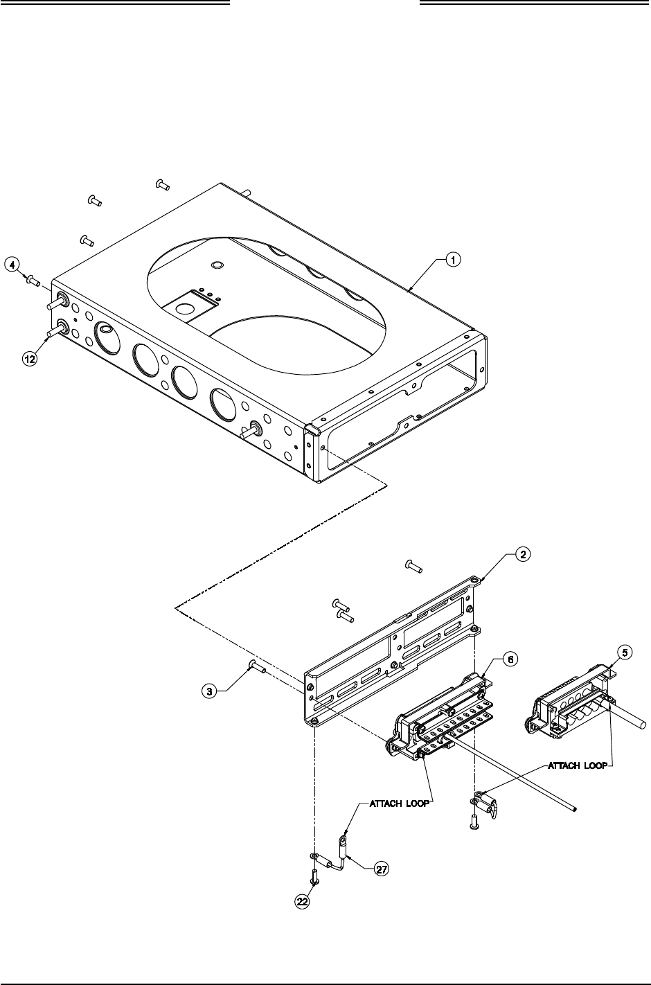
Lynx NGT-9000s
Installation Manual
4. Secure Rear Plate (item 2) to Panel Rack P/N 9010-17022-01 (item 1) using 4 Screws P/N NAS514-
P-440-5 (item 4).
5. Place the assembled Panel Rack P/N 9010-17022-01 (item 1) in the location selected in paragraph 2.3.1.
6. Secure Panel Rack using 6 Screws P/N MS35206-230 (item 12).
Figure 2-12: Panel Assembly
Page 2-20 Installation 0040-17001-01
January 15, 2015 Revision A
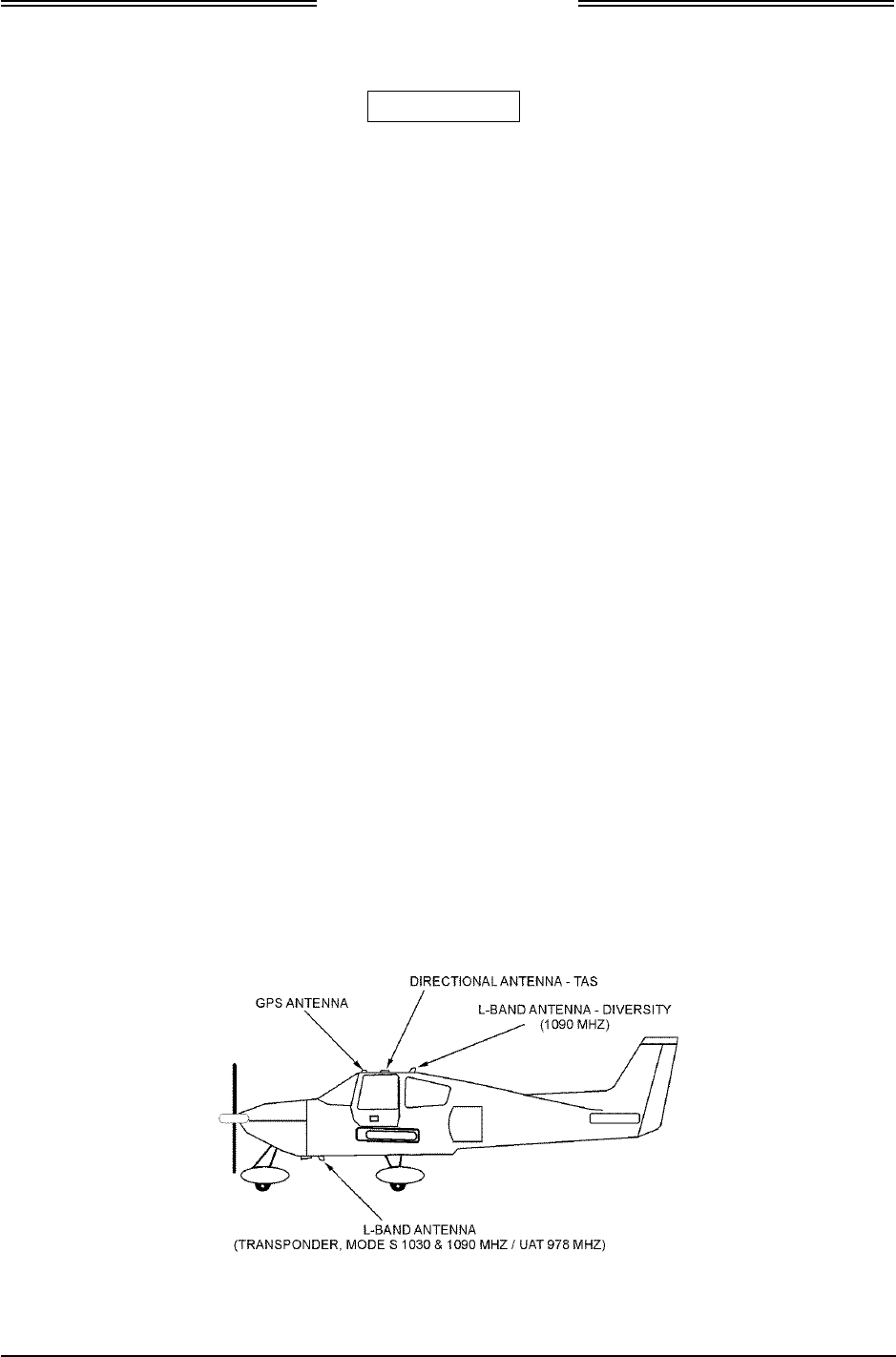
Lynx NGT-9000s
Installation Manual
2.3.4 Installation
CAUTIONS
1. Do not press or contact the display surface of the unit when
inserting into the Rack.
2. Panel Retainer torque limit is 5.0 inch-pounds.
1. Prior to inserting unit in panel ensure that the Panel Retainer screw is fully disengaged. Use a 3/32
Hex Head Driver and insert into the Panel Retainer access on the bottom left of the unit bezel. Rotate
the Hex Driver counterclockwise until it stops.
2. Insert the unit in rack allowing the alignment guides to settle the unit into place. Press the sides of
the unit until the back side of the bezel is against the rack.
3. Rotate the Panel Retainer clockwise until the unit is fully seated (approximately 40 turns). The unit is
fully seated when the display backplate contacts the lower front edge of the panel.
2.3.5 Antenna Installation Guidelines
This information provides general installation guidance to ensure the installed antennas meet the
requirements for the Lynx NGT-9000s. Installation approval for the GPS and L-band antennas is not
provided by the instructions provided in this manual.
• Installation approval for the GPS and L-band antennas is not provided by the instructions provided in
this manual.
• All antenna cables should be clearly marked as both connections use TNC connectors.
• Cable requirements are located in paragraph 2.3.2. Cable vendors and approved antenna
manufactures are located in the General Information section.
• An example of antenna placement is shown in Figure 2-13. Refer to the aircraft manufacturer's data
and the antenna manufacturer's installation instructions to mount the antenna. The installer may use
other FAA approved data to gain a separate antenna installation approval. Four L-band antenna
location configurations are available and are detailed below:
• Single bottom omnidirectional (L-band) antenna (no TAS, no diversity)
• Bottom omnidirectional (L-band), top omnidirectional (no TAS, diversity capable)
• Bottom omnidirectional (L-band), bottom directional (TAS capable, no diversity)- due to both being
bottom mount (Helicopter)
• All configurations have a top GPS antenna
Figure 2-13: Example of Antenna Mounting Locations
0040-17001-01 Installation Page 2-21
Revision A January 15, 2015

Lynx NGT-9000s
Installation Manual
2.3.5.1 GPS Antenna
The GPS antenna performance is critical to the performance of the Lynx NGT-9000s. The antenna must
meet the minimum performance requirements for the Lynx NGT-9000s.
• The recommended antenna is a DO-301 compliant antenna meeting the requirements of TSO-C190.
For installations where the aircraft has an existing antenna complying with DO-228 (TSO-C144a),
the unit may be installed utilizing this antenna, as per DO-229D Note 1, Section 2.1.1.10. Use the
antenna location information below to verify an existing antenna location is acceptable for use.
• The performance of the unit is affected by the gain, noise figure, impedance, and frequency
selectivity characteristics of the antenna. The unit should be used only with the recommended
antenna and cable. Use of other antennas or cables may not meet all the performance characteristics
specified in DO-229D.
• The cable including connectors, loss should not exceed 10dB.
2.3.5.1.1 GPS Antenna Location
The following guidance provides information to aid the installer in determining the best location is
selected for the installation of the GPS Antenna.
The installation guidelines presented here meet the intent of AC 20-138C Chapter 12, Section 12-1.
NOTE
Not all the listed installation guidelines may be possible on all aircraft.
The guidelines are listed in order of importance. The chances of optimal
signal strength are decreased if the guidelines are not followed.
1. The antenna must be located on the top of the aircraft and should be mounted in a location to
minimize the effects of airframe shadowing during typical maneuvers. Typically mounting farther
away from the tail section reduces signal blockage seen by the antenna.
2. Mount the antenna as close to level as possible with respect to the normal cruise flight attitude of the
aircraft. If the normal flight attitude is not known, substitute with the waterline, which is typically
referenced as level while performing a weight and balance check. A shim may be used to level the
antenna.
3. The antenna should be mounted no closer than 3 feet from any VHF COM antenna or any other
antenna, which may emit harmonic interference at the L1 frequency of 1575.42 MHz. An aircraft
EMI check can verify the degradation of GPS in the presence of interference signals.
• If an EMI check reveals unacceptable interference, either insert a GPS notch filter in line with
the offending VHF COM or select a different GPS Antenna location.
4. To maintain a constant gain pattern and limit degradation by the windscreen, avoid mounting the
antenna closer than 3 inches from the windscreen.
5. It is permissible to temporarily locate the GPS Antenna with a coaxial cable connected to the unit
and check the GPS performance as described in the installation checkout section. Permanently mount
the antenna once a suitable location has been verified.
6. Once the antenna mounting position has been established, route the coaxial cable from the antenna to
the Lynx NGT-9000s. Proper selection of coaxial cable and assembly of connectors is critical to GPS
signal performance.
7. For installations on rotorcraft, ensure that the rotor blades do not interfere with the GPS received
signal. This problem has been experienced in some rotorcraft and varies with rotation rate.
Page 2-22 Installation 0040-17001-01
January 15, 2015 Revision A

Lynx NGT-9000s
Installation Manual
2.3.5.1.2 GPS Antenna Installation
Refer to the aircraft manufacturer's data and the antenna manufacturer's installation instructions to mount
the antenna. The installer may use other FAA approved data to gain a separate antenna installation
approval.
1. Electrical Bonding Requirements:
The GPS/WAAS antenna requires a minimum ground plane radius of 7.5 inches around the
perimeter of the antenna. For metal aircraft, the surrounding metal skin on which the antenna is
mounted supplies the ground plane. For non-metal aircraft, the ground plane can be composed of
heavy duty aluminum foil tape, such as 3M PIN 438 or other adhesive backed dead soft aluminum
foil minimum 0.012 inches thick. It should be noted that if the antenna is struck by lightning, the foil
by itself may not be sufficient to dissipate lightning currents. Additional protection may be needed
depending on the construction of the structure to which the antenna is mounted.
• The electrical bonding requirements stated in paragraph 2.3.2 must be met.
• To prepare an aluminum surface for proper bonding, refer to SAE ARP1870.
2. Connection to the antenna should be made in accordance with the system interconnect diagram
Figure 2-3.
2.3.5.2 L-Band Antenna
The L-band antenna is used to must meet the minimum performance requirements for the Lynx NGT-9000s.
Antennas meeting the minimum performance specifications needed by the Lynx NGT-9000s may already
be installed in the aircraft and may be available for use. Use the antenna location information below to
verify an existing antenna location is acceptable for use.
2.3.5.2.1 L-band Antenna Location
The L-band antenna installation should be installed in accordance with AC 43.12-2A Chapter 3. The
following guidance provides information to aid the installer in determining that the best location is
selected for the installation of the L-band Antenna.
• The primary L-Band antenna (978 MHz /1030 & 1090 MHz) must be mounted vertically on the
bottom of the aircraft fuselage. The antenna shall be located to minimize obstruction to fields in the
horizontal plane.
• The optional Diversity L-Band antenna (1090 MHz) must be mounted vertically on the top of the
aircraft as shown in Figure 2-13. Horizontal separation from the bottom mounted L-band antenna
must be no more than 25 feet (7.6 meters).
• The total attenuation including connectors shall not exceed 1.5 dB. Based on this, the length of the
cable can be decided assuming RG-400 cable. RG type coaxial cable insertion loss can vary
significantly between manufacturers. Refer to the cable manufacturer's specification sheet for actual
attenuation (insertion loss) for the cable being used.
• The Antenna(s) should be located away from major protrusions, such as engine(s), propeller(s), and
antenna masts. It should be as far as practical from landing gear doors, access doors, or other
openings that could affect its radiation pattern.
• The Antenna(s) must be mounted no closer than 20 inches from any FADEC (Full Authority Digital
Engine Control).
• The bottom L-Band must be mounted no closer than 7 feet to any DME antenna.
• The Antenna(s) must be mounted no closer than 36 inches to any TAS/TCAS antenna.
• The Antenna(s) should be mounted no closer than 3 feet from any GPS antenna.
0040-17001-01 Installation Page 2-23
Revision A January 15, 2015

Lynx NGT-9000s
Installation Manual
2.3.5.3 L-Band Antenna Installation
Refer to the aircraft manufacturer's data and the antenna manufacturer's installation instructions to mount
the antenna(s). The installer may use other FAA approved data to gain a separate antenna installation
approval.
• Electrical Bonding Requirements:
Each L-Band antenna requires a minimum ground plane radius of 12 inches of contiguous metal (no
access panels, etc.) around the perimeter of the antenna. For metal aircraft, the surrounding metal
skin on which the antenna is mounted supplies the ground plane. For non-metal aircraft, the ground
plane can be composed of heavy duty aluminum foil tape, such as 3M PIN 438 or other adhesive
backed dead soft aluminum foil minimum 0.012 inches thick. It should be noted that if the antenna is
struck by lightning, the foil by itself may not be sufficient to dissipate lightning currents. Additional
protection may be needed depending on the construction of the structure to which the antenna is
mounted.
The electrical bonding requirements stated in paragraph 2.3.2 must be met.
• Connection to the antenna should be made in accordance with the system interconnect diagram
Figure 2-3.
• All antenna cables should be clearly marked as both connections use TNC connectors.
• Acceptable coaxial cable attenuation including connectors shall be less than 1.5 dB at 978 MHz.
• Reference General Information Section – Antenna Cables for L-Band Antenna cable loss and
minimum antenna spacing requirements.
• Refer to General Information Section - lists some suitable cable types. Any 50ohm, double-shielded
coaxial cable assembly that meets airworthiness requirements and the acceptable attenuation
requirements (including connectors) may be used. When computing cable loss, a typical loss of 0.2
dB can be used for each connection. Refer to paragraph 2.3 step 2 for antenna electrical bonding
requirements.
2.3.5.4 Installation Guidelines for NY156 (TCAS) and NY164 (TCAS) Directional Antenna
Connections are made through two TNC and one BNC connector. To ensure a tight seal between the
airframe and antenna, an O-ring seal (i.e., an O-ring groove for an MS28775-044 O-ring) has been
incorporated into the design. An O-ring is supplied with each antenna and must be installed when
mounting the antenna. Installation kits associated with various airframes are described in the General
Information section along with the contents of each kit.
Page 2-24 Installation 0040-17001-01
January 15, 2015 Revision A
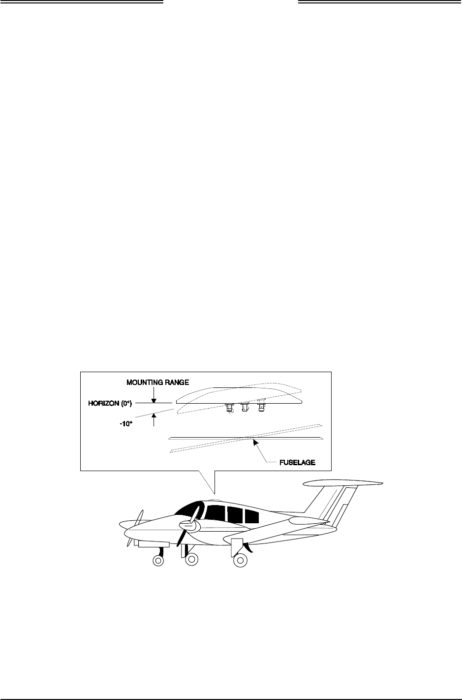
Lynx NGT-9000s
Installation Manual
2.3.5.4.1 Directional Antenna Location
Location is an important factor for maximum antenna performance. Optimum location for a particular
aircraft type is usually available from the aircraft manufacturer. See Figure 2-15 for Antenna Outline
dimensions.
1. In selecting a location, consider the following:
• The mounting site should be on the top forward fuselage, as close to the centerline as possible,
and within -10° of the in-flight horizon (see Figure 2-14).
• The optimum mounting point for maximum coverage is as far forward as possible without
exceeding the -10° forward pitch.
• If necessary, consideration should be given to relocating other antennas to obtain the furthest
forward location for the directional antenna.
• The antenna should be mounted on the aircraft with at least 20 dB isolation (about 30 inches
(76.2 cm)) from other L-band frequency antennas and 24 inches (61.0 cm) from other antennas
or obstructions.
• The ground-plane should be as large as possible, a 30-inch (76.2 cm) ground-plane diameter is
recommended.
• Refer to the guidelines given for the GPS Antenna and L-Band (UAT/1090) Antennas for
additional spacing requirements.
• The directional antenna can be bottom mounted only if a suitable top mount location is not
available. Each bottom mount installation must be evaluated on a case-by-case basis. Before
starting a bottom mount installation, contact Field Service Engineering at 1-800-453-0288 or 1-
616-949-6600. Note - The bottom mount directional antenna eliminates the diversity option.
Figure 2-14: Directional Antenna Mounting Location
0040-17001-01 Installation Page 2-25
Revision A January 15, 2015
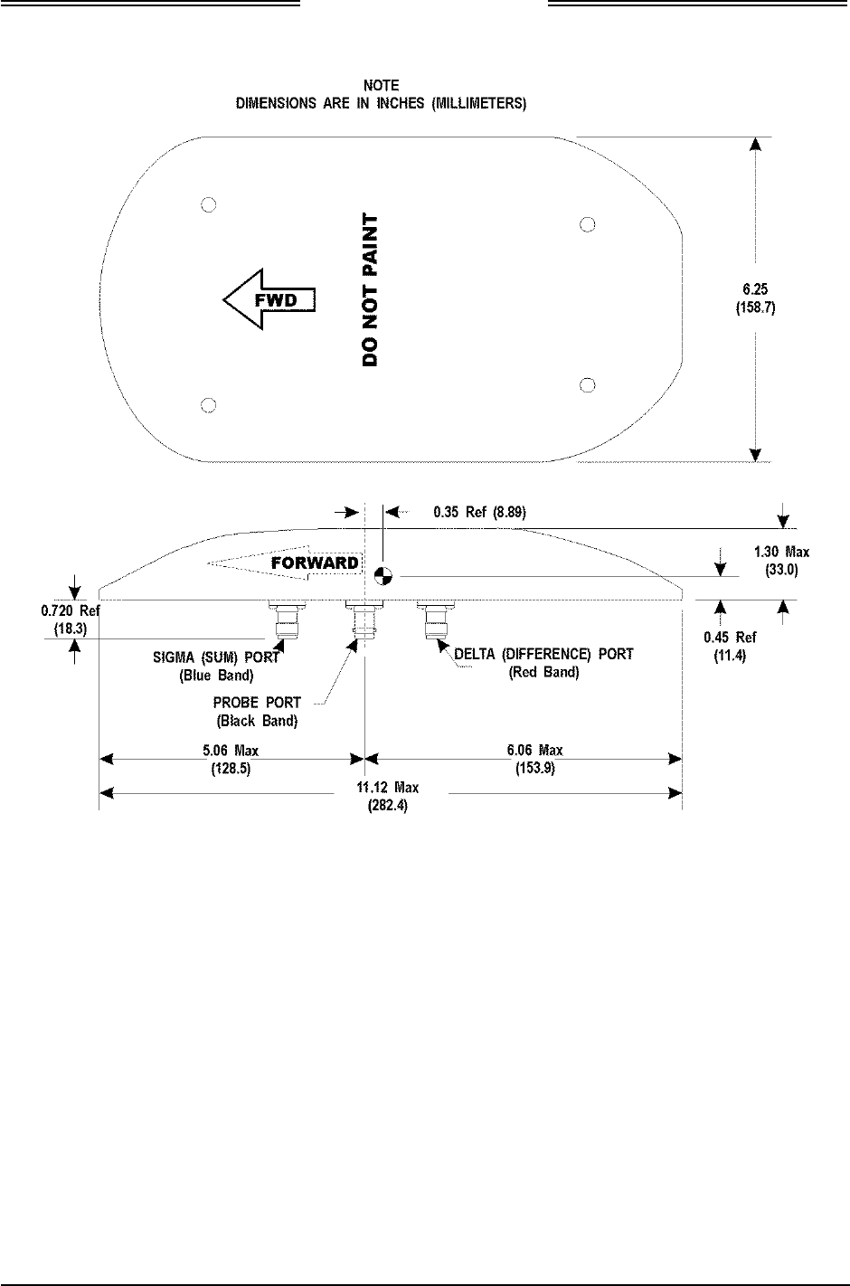
Lynx NGT-9000s
Installation Manual
Figure 2-15: NY156 / NY164 Directional Antenna Outline Dimensions
Page 2-26 Installation 0040-17001-01
January 15, 2015 Revision A

Lynx NGT-9000s
Installation Manual
2.3.5.5 Installation
1. Use the following information to the extent necessary to install the directional antenna.
• Standard installation practices prescribed in FAA Advisory Circular 43.13 must be followed.
• The installer must ensure the immediate antenna installation area is clean and prepared so that
the antenna is electrically bonded (metal-to-metal contact) to the aircraft. To provide optimum
bonding through the mounting holes, prepare the surfaces with Alodine No. 1001.
• To facilitate mounting to the airframe, the dimensions shown in Figure 2-16 can be used to
locate and drill mounting and connector access holes.
• Connection to the antenna should be made in accordance with the system interconnect diagram
Figure 2-3.
NOTE
A doubler plate (not supplied) is required to reinforce the aircraft skin.
2. Connect each of the three antenna cables. Check to ensure that each cable is connected to the correct
antenna connector. Each connector/cable has a matching color band (see note paragraph.).
3. Attach the antenna to the aircraft, with the special adapter plate and o-ring, using 10-32 hardware
provided. See Figure 2-17.
NOTES
1. Before installing the antenna on an aircraft remove the tape, which
holds the O-RING gasket in place during shipment (refer to SL-206).
If the O-ring is in a separate bag, remove and install it in the O-ring
groove on the bottom of the antenna.
2. For pressurized aircraft, use a sealant that meets the requirements of
SAE AMS-S-8802 such as Flamemaster CS3204 class B. For non-
pressurized aircraft, use a non-corrosive sealant that meets the
physical requirements of MIL-A-46146 such as General Electric
RTV162.
0040-17001-01 Installation Page 2-27
Revision A January 15, 2015
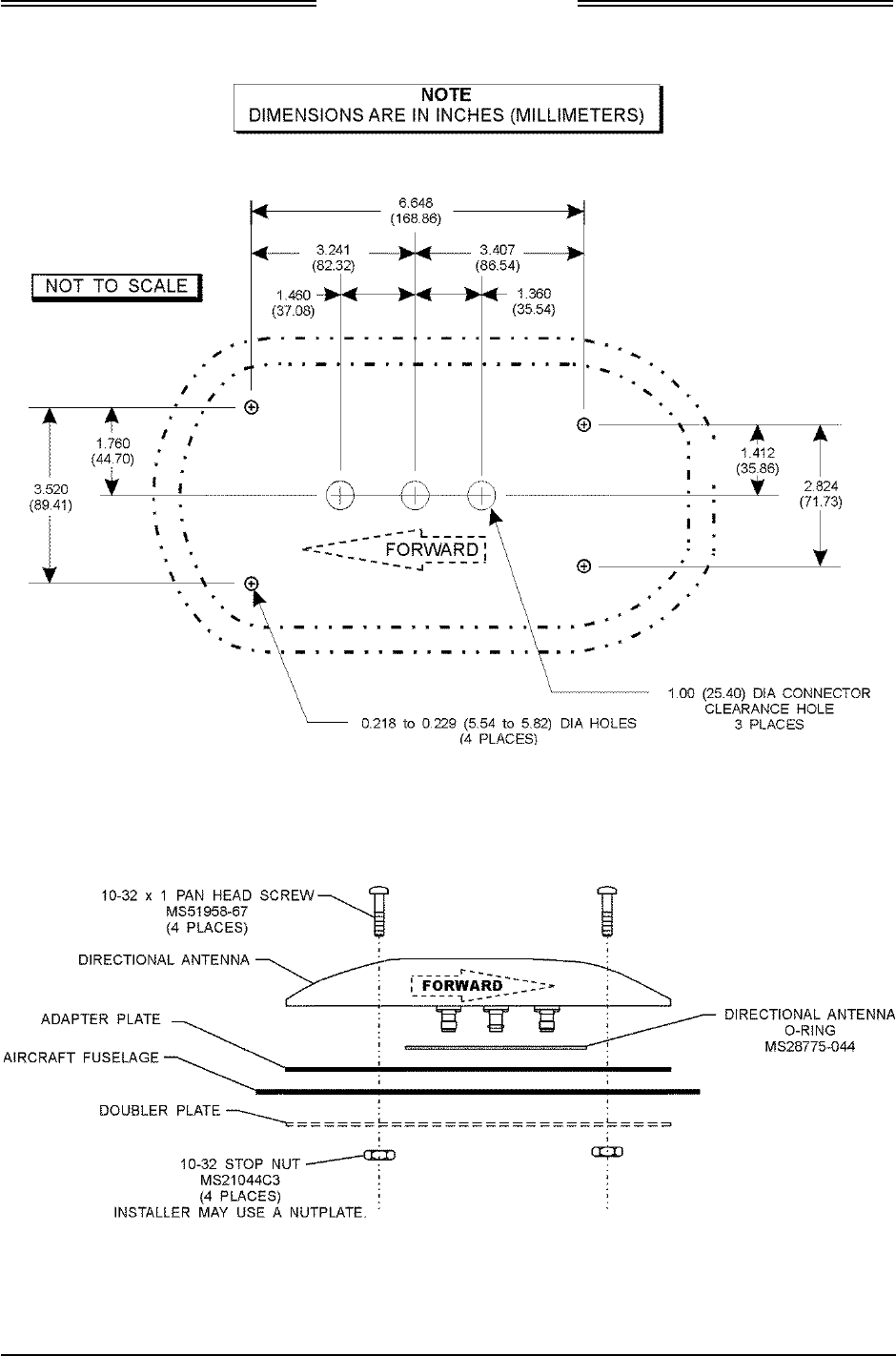
Lynx NGT-9000s
Installation Manual
Figure 2-16: Antenna Mounting Holes
Figure 2-17: Directional Antenna Installation
Page 2-28 Installation 0040-17001-01
January 15, 2015 Revision A

Lynx NGT-9000s
Installation Manual
2.3.6 Remove and Replacement Procedures
If the unit or one of its system components requires removal after initial installation, replace it using the
instructions given in the maintenance section of this manual.
0040-17001-01 Installation Page 2-29
Revision A January 15, 2015

Lynx NGT-9000s
Installation Manual
This page intentionally blank
Page 2-30 Installation 0040-17001-01
January 15, 2015 Revision A
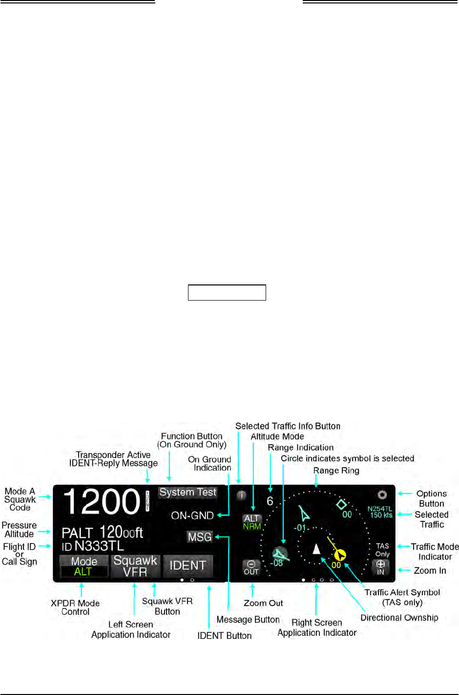
Lynx NGT-9000
Installation Manual
Section
3
Installation Checkout
3.1 INTRODUCTION
This section contains instructions for the configuration and checkout of the Lynx NGT-9000s. Refer to the
fault isolation information provided in the maintenance manual for help in correcting installation issues
found during checkout. Refer to the General Information section - Equipment Required Not Supplied for
details on equipment used in this section.
A Log Sheet is available in Appendix C to record the Configuration and Checkout information. It should
be filled out prior to performing this procedure.
NOTE
These procedures assume that the mounting, wiring, power, and antenna
requirements have been checked out according to the instructions given
in the installation section.
CAUTIONS
1. Operating the unit with the GPS antenna connected and the L-
Band antenna NOT connected may damage the unit.
2. All antenna connections must be connected prior to operation.
3.2 BASIC OPERATION
The unit uses a touch screen display to select, input, and adjust information on the screen using gestures
(actions); such as tap, momentary press, drag, or swipe. See Figure 3-1.
Figure 3-1: Transponder/Traffic Screens
0040-17001-01 Installation Checkout Page 3-1
Revision A January 15, 2015

Lynx NGT-9000
Installation Manual
• Buttons are typically gray background color with white or green text. When a button is pressed the
background highlights in blue. A button function that is inhibited has its button label grayed out.
Buttons with an amber background color is inactive.
• The display for the unit is divided into a left and right screen. Each screen has access to a particular
application. Accessing the applications is done using a horizontal Slide action to drag the desired
application screen into view.
An Application indicator is located at the bottom of the left and right screen. The indicator shows the
number of available applications for that side of the display as well as the current application setting.
Each application can slide into view using both Drag and Swipe actions.
The left screen applications are designated as “Transponder” and “Alternate Traffic”. The right
screen applications are designated as “Traffic”, FIS-B Graphic”, FIS-B Graphic Winds & Temp”,
and FIS-B Text Data”. The left screen also shows the information screens (GPS, brightness control,
etc.)
• A version screen is shown at start up. It identifies version information for the units Application
Software (Flight Sw), Firmware (Platform and GPS), GPS/UAT Receiver SW, Airport Database
(Airport DB), and Map Database (Map DB).
• The display brightness is automatically adjusted using an ambient light sensor and can also be
adjusted pressing the Gear icon on the left application screen followed by the dimming button.
3.2.1 Power On
1. Verify the circuit breaker for the Lynx NGT-9000s is closed.
2. Connect aircraft to external power source to conserve aircraft battery power.
3. Apply power to the unit and system component using applicable essential or emergency electrical
buses.
• Initialization and self-tests begin.
4. The splash screen is displayed in less than 5 seconds.
• The company name/Logo is shown on the left side and the product name on the right.
5. The System Status is shown on the left side in less than 20 seconds
• If a System Status is “System Fail” or “System Degraded” message is shown, then tap the
Continue button to proceed to normal operation. See Figure 3-19.
Page 3-2 Installation Checkout 0040-17001-01
January 15, 2015 Revision A

Lynx NGT-9000
Installation Manual
3.3 MAINTENANCE PC
The procedures for installation checkout require the use of a Maintenance PC (MPC), Lynx Maintenance
Appliance Tool (Lynx MAT), LynxMSS USB Driver, and a USB cable.
A compatible Lynx MAT revision must be used to successfully communicate with Lynx NGT-9000s.
Refer to the Software Revisions information in the General information section for details.
NOTE
The revision of the Lynx MAT must be compatible with the unit’s
software release. Refer to software revisions in the General information
section for details. The revision of the Lynx MAT can be found in the
Help/About menu at the top of the screen.
Persons performing the checkout should monitor the Lynx MAT status bar. The bottom left corner of the
screen provides information on connection type and communication status.
• The communication status is either “Connected – green indicator” or “Not Connected – red indicator”.
• Messages are also shown on the right side of the status bar providing guidance to the user.
• The operational status of the unit is shown on the Lynx MAT and is located at the top of the panel
(next to the model ID) and on the status bar. The operational status is either “Flight” or “Maint”.
When “Flight” status is shown the unit is in either “Normal Operation” or in “Ground Test” modes.
When “Maint” status is shown the unit is in “Maintenance” mode, with or without Wifi. The Restart
function of the Lynx MAT may be used to restart into Normal Operational mode, Maintenance mode
(with or without Wifi), or Ground Test mode.
• Maintenance mode (Maint) can be entered within the first 2 minutes from power-on irrespective of
Air/Ground state. After 2 minutes, maintenance mode can only be entered if the Air/Ground state is
On-Ground.
• The Air/Ground state is determined through a Weight On Wheels (WOW) input and GPS
Groundspeed. The air/ground state is initially determined based on the last known air/ground state
saved in non-volatile memory. When sensor inputs have become available and the state may be
determined based on sensors, the installed configuration is used to guide the air/ground algorithm to
update the current air/ground state.
NOTE
When the unit is restarted in maintenance mode the cooling fan is
enabled and the ADS-B discrete output is set to ground, which enables
the ADS-B Out Fail Annunciator lamp if installed.
1. Do the following to connect and establish communication between the MPC and the unit via the
USB connection.
a. Apply power to the unit as indicated in paragraph 3.2.1.
b. Connect USB cable between MPC and the unit.
c. From the Lynx MAT menu select ConnectZNGT9000 Z USB. See Figure 3-2.
0040-17001-01 Installation Checkout Page 3-3
Revision A January 15, 2015
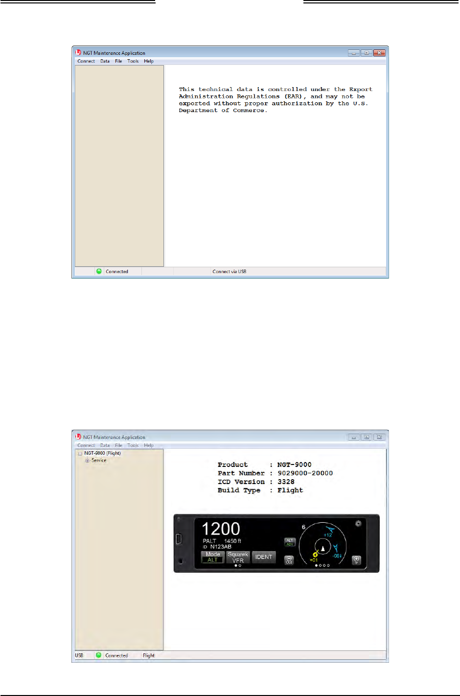
Lynx NGT-9000
Installation Manual
Figure 3-2: Maintenance Application Tool – Main Page
d. Communication is established when the Lynx MAT left view panel changes from grey to tan
and the message “Connected” is shown in the lower communication bar. See Figure 3-3.
• If “Not Connected – red indicator” is shown, then check the USB cable for proper
connection.
• If a “Response timeout for write request” message is seen on the status bar, then the unit is
not responding to requests. Cycle power to the unit.
• When the unit is in maintenance mode the ADS-B Out Fail lamp is ON (if installed).
Figure 3-3: Lynx MAT – Main Screen
Page 3-4 Installation Checkout 0040-17001-01
January 15, 2015 Revision A
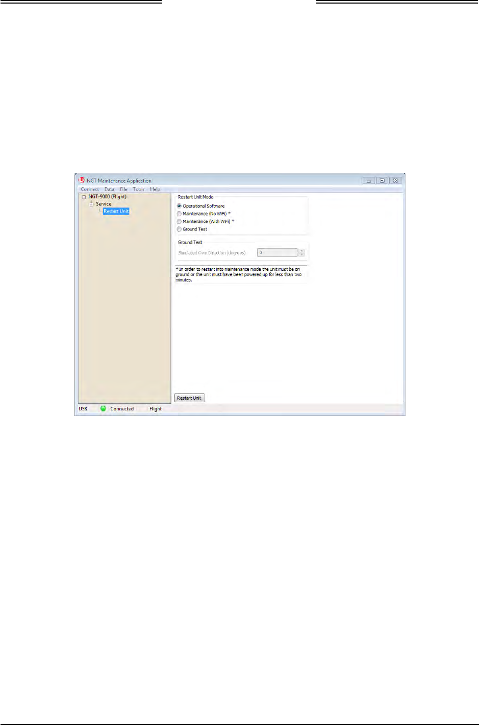
Lynx NGT-9000
Installation Manual
2. The unit can be restarted (power cycled) by using the Lynx MAT as follows:
a. From the Lynx MAT panel select ServiceZRestart Unit. See Figure 3-4.
b. From the Restart Unit screen select Maintenance (No WiFi)
c. Click on the Restart Unit button at the bottom of the main screen.
d. The unit is ready for configuration setup when the maintenance screen is shown on the unit
display. See Figure 3-6.
Figure 3-4: Lynx MAT – Restart Unit
3. Do the following to connect and establish communication between the MPC and the unit via the
WiFi connection. (The WiFi connection is optional.)
NOTE
The Configure WiFi Accessory procedure described in 3.5 must be
completed before the unit can establish a WiFi connection.
a. After communication has been established using the instructions in step 1, WiFi communication
can be established with the unit for installation using the WiFi option.
b. From the Lynx MAT panel select ServiceZ Restart Unit.
c. Select Maintenance (With WiFi)
d. Press the Restart Unit button.
e. From the Lynx MAT menu select ConnectZNGT9000 ZWiFi.
f. Connection should be established. If not, than restart the process begun in step 2.a.
g. Remove USB cable.
0040-17001-01 Installation Checkout Page 3-5
Revision A January 15, 2015
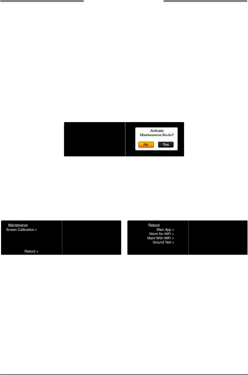
Lynx NGT-9000
Installation Manual
3.4 MAINTENANCE MODE
The unit can enter Maintenance mode without the use of a MPC using the following procedure.
NOTE
If the unit has detected that it is in-air, then maintenance mode can only
be entered in the first two minutes of operation.
1. Apply power to the unit as indicated in paragraph 3.2.1.
2. With the splash screen showing press and hold (continue holding when the status and version screens
are showing) in the lower left corner of the display until the Activate Maintenance Mode window is
shown on the right screen. See Figure 3-5.
Figure 3-5: Activate Maintenance Mode Window
3. Tap the Yes button to restart the unit in Maintenance Mode. Note - Tapping the No screen button or
10 seconds of inactivity starts normal operation mode. The Maintenance Mode windows are shown
in Figure 3-6.
• Note: Some failure conditions automatically activate the maintenance mode. The reason for the
automatic activation is shown on the screen.
Main Screen Reboot Screen
Figure 3-6: Maintenance Mode Screens
4. From the Main Screen tap the Reboot text.
5. From the Reboot menu tap the Maint No-WiFi >.
• A maintenance screen is shown on the unit while in maintenance mode.
Page 3-6 Installation Checkout 0040-17001-01
January 15, 2015 Revision A
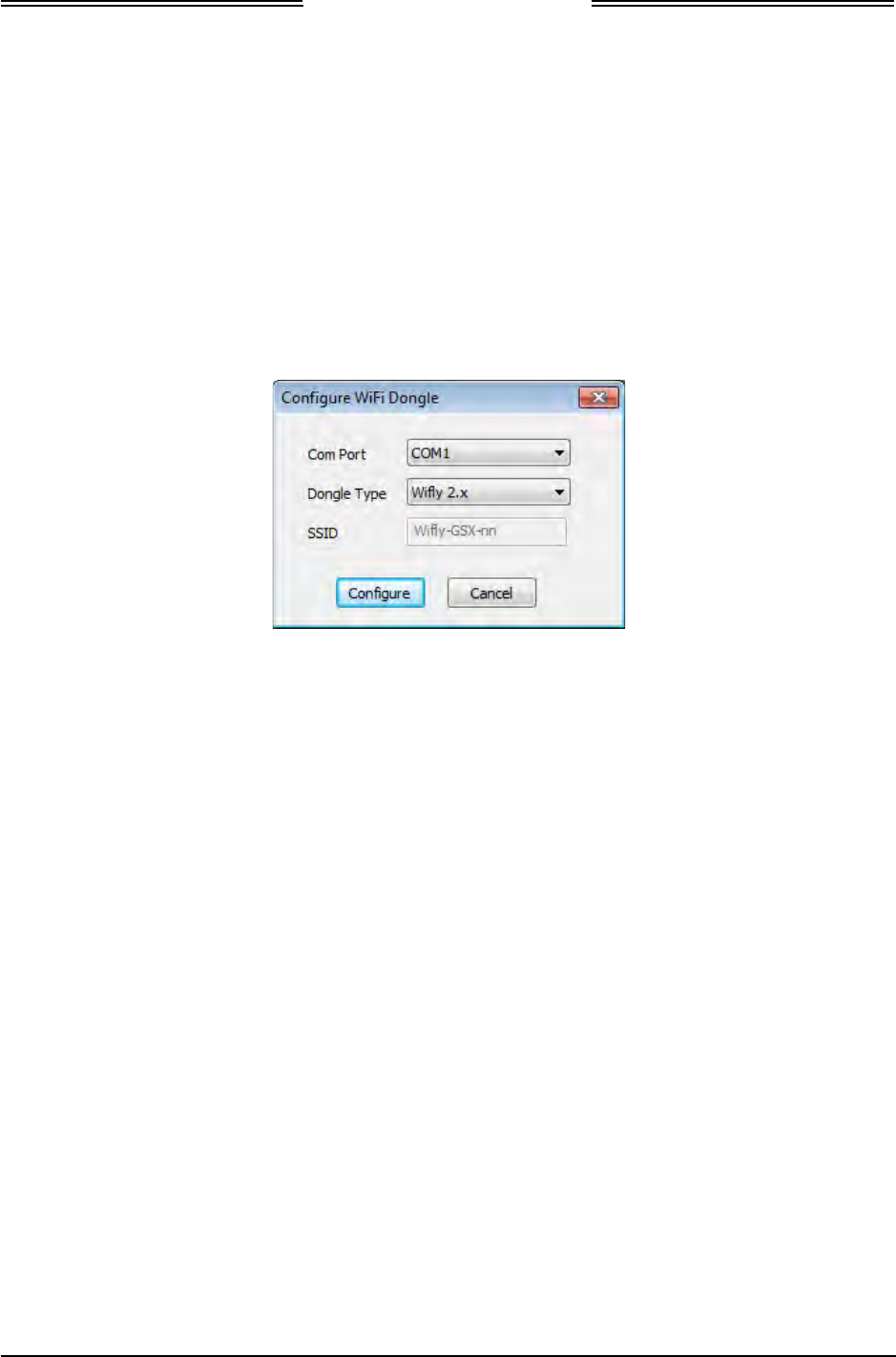
Lynx NGT-9000
Installation Manual
3.5 CONFIGURE WIFI ACCESSORY
This procedure requires a Maintenance PC (MPC), Lynx Maintenance Application Tool (Lynx MAT),
and a standard Null Modem cable (DB9 F/F).
These procedures assume the following:
• The Lynx MAT is active on the MPC.
1. Connect WiFi Accessory to the MPC via the Com Port that the dongle is connected to using a standard
Null Modem cable.
2. From the Lynx MAT menu select ToolsZConfigure WiFi Dongle. See Figure 3-7.
Figure 3-7: Lynx MAT – WiFi Accessory
3. If using model RN370 verify that dip switches 1 -4 are in the off position (i.e. towards the connector
side of the dongle).
4. Select the Com Port (typically COM1).
5. Select the Dongle (accessory) Type.
6. Enter the SSID (4.x only) if the entry field is not grayed out and accessible. Otherwise the SSID is
already loaded.
7. Click “Configure” to begin. A message is shown to indicate configuration complete or if
configuration could not be completed.
8. If the configuration could not be completed, then check the following:
• Cable connection
• Com port connection
• Accessory type
• Correct SSID
• Check batteries for the WiFi Accessory
9. After the configuration is complete remove the serial cable and cycle power to the dongle.
10. Connect the accessory to the aircraft wiring harness connecting to the Lynx NGT-9000s.
11. Verify that the SSID name can be seen with a WI-FI device such as laptop or PED.
Note - The SSID may show the default SSID being used, which is typically Wifly-Serial-nn, where
nn is variable per dongle.
0040-17001-01 Installation Checkout Page 3-7
Revision A January 15, 2015
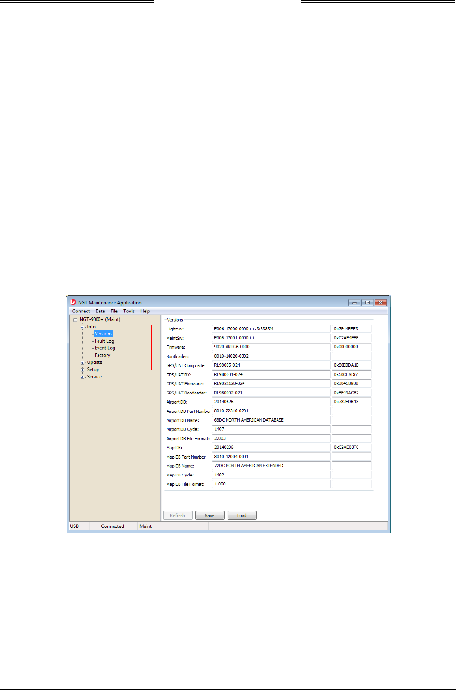
Lynx NGT-9000
Installation Manual
3.6 VERIFY SOFTWARE VERSION
The Maintenance PC (MPC) and Maintenance Application Tool (Lynx MAT) are used to interface with
the unit to load software/firmware/databases, view factory / version data, and retrieve fault / event logs.
These procedures assume the following:
• Power is being supplied to the aircraft and unit.
• The Lynx MAT is active on the MPC.
• The MPC is connected to the unit via the USB interface
• The MPC and unit are communicating. From the Lynx MAT panel select
ConnectZNGT9000ZUSB. This is required each time the unit power is cycled.
1. From the Lynx MAT select InfoZVersions. See Figure 3-8.
2. Use the versions screen to verify that the field loadable software is correct for this installation.
Details on software part numbers and versions are available in the General Information section under
paragraph heading “Software Versions”.
• If a software version is found to be incorrect, update using the procedures located in the
maintenance section of this manual.
Figure 3-8: Lynx MAT – Check Versions
Page 3-8 Installation Checkout 0040-17001-01
January 15, 2015 Revision A

Lynx NGT-9000
Installation Manual
3.7 SELECT CONFIGURATION OPTIONS
This procedure is used to configure the Lynx NGT-9000s and must be completed prior to performing the
Installation Checkout for first time installations. The Log Sheet provided in Appendix C should be filled
out in preparation for this procedure and maintained with the aircrafts permanent records.
CAUTION
A “Warning” message is shown when the user first attempts an operation
that requires confirmation from the user stating “Changes should be done
by trained service personnel”. The user will need to press the confirm
button to acknowledge this warning.
This message is to warn unauthorized or untrained personnel to stop
what they are doing before they mis-configure or damage the unit.
• If a configuration file has already been created using the Lynx MAT Backup function, then it may be
used to load the data options. The configuration restore procedure is located in the maintenance
section of this manual.
• Unlock codes are required to enable TAS and Diversity configuration selections. The unlock codes
are typically shipped with the unit. If the unlock codes are not included, contact L-3 Avionics
Systems Customer Service to obtain the codes.
• If the Lynx MAT is not connected or is disconnected the left side panel color changes to a light grey
and the “Not Connected” message is displayed at the bottom of the tool screen. Re-connect by doing
the following - from the Lynx MAT panel select ConnectZNGT9000ZUSB. This is required each
time the unit power is cycled.
• Place the curser over option titles to view tool tips (not always available).
• No configuration changes take effect until they are entered, applied, and the unit is restarted.
• Pressing “Apply” from any setup/configuration/modify screen applies all changes from all screens.
These procedures assume the following:
• Power is being supplied to the aircraft and unit.
• The Lynx MAT is active on the MPC.
• The MPC is connected to the unit via the USB interface
• The MPC and unit are communicating.
0040-17001-01 Installation Checkout Page 3-9
Revision A January 15, 2015
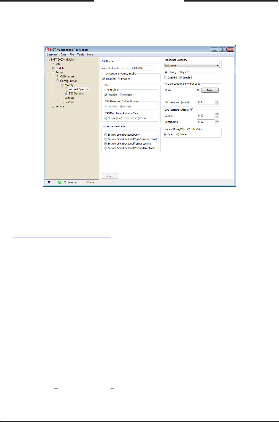
Lynx NGT-9000
Installation Manual
3.7.1 Aircraft Specific Options
From the Lynx MAT select Setup… Configuration Z Modify Z Aircraft Specific. See Figure 3-9. Enter
the information specific to the installation for the intended certification.
Figure 3-9: Lynx MAT –Aircraft Specific Options
1. Tail Number: Enter the tail number the aircraft that the unit is being installed in.
2. Mode S Identifier: 24 bit ICAO address code. Eight octal digits. The code can be obtained from
either the aircraft registration certificate or the N number inquiry page
http://registry.faa.gov/aircraftinquiry/.
3. Transponder Diversity Enable: Select Disabled or Enabled. This selection only works for models
of the Lynx NGT-9000 with Diversity functionality.
• This feature requires a Mode S Identifier to be entered.
• This feature requires a unlock code. Refer to the general information section of this manual for
details on how to obtain this code.
4. TAS
a. TAS Enable: Select Disabled or Enabled. This selection only works for models of the Lynx
NGT-9000 with TAS functionality. When enabled the aural alert “Traffic, Traffic” is heard over
the audio system when traffic advisory (TA) is first detected.
• This feature requires a Mode S Identifier to be entered. If the Mode S Identifier is modified
the diversity and TAS enable options, if currently enabled, will be disabled. See the
maintenance section for details.
• This feature requires a unlock code. Refer to the general information section of this manual
for details on how to obtain this code.
b. TAS Extended Callout Enable: Select Disabled or Enabled. When enabled the aural alert
“Traffic, Traffic” is heard over the audio system when traffic advisory (TA) is first detected along
with the following aural information: relative clock bearing (e.g. “12 O’clock”), relative altitude
(“High” if > to 50ft or “Low” if < to -50ft or “Same Altitude” if > -50ft and < 50ft of own
altitude), and range in nautical miles (slant range if TA is NAR or Flat range if TA is not NAR).
• This feature requires “TAS Enable” to be enabled.
Page 3-10 Installation Checkout 0040-17001-01
January 15, 2015 Revision A

Lynx NGT-9000
Installation Manual
c. TAS Directional Antenna Type:
• This feature requires “TAS Enable” to be enabled.
• Select either NY164 (TAS) or NY156 (TCAS).
5. Antenna Installation: This setting is dependent on both the TAS enabled and diversity enabled
settings. The options available change depending on current Diversity enabled and TAS enabled
settings. Select the antenna installation using the following guidelines.
• When Diversity is enabled and TAS is disabled, then the only valid antenna selection is
Bottom Omnidirectional/Top Omnidirectional.
• When Diversity is disabled and TAS is enabled, then antenna install may be either
Bottom Omnidirectional/Top Directional or Bottom Omnidirectional/Bottom Direction.
Note - When changes are applied validation occurs and if a valid option is not selected then a
warning message is shown. No changes are applied.
• Broadcast Category: This information provides an indication of the aircrafts size and
performance capabilities. Emitter categories are defined below:
EMITTER CATEGORY DESCRIPTION
Unknown No aircraft type information. If no emitter category fits the installation, seek
guidance from the FAA.
Light Light (ICAO) < 15,500 lbs. This includes very light aircraft (light sport aircraft)
that do not meet the requirements of 14 CFR 103.1.
Small Small – 15,500 to 75,000 lbs.
Large Large – 75,000 to 300,000 lbs.
High Vortex Large High Vortex Large - 75,000 to 300,000 lbs. that has been determined to
generate a high wake vortex. (e.g. B757).
Heavy Heavy (ICAO) - > 300,000 lbs
High Performance Highly Maneuverable > 5G acceleration and > TAS high speed.
Rotorcraft Any rotorcraft regardless of weight.
Glider/Sailplane Any Glider/Sailplane regardless of weight.
Lighter than Air Any lighter than air (airship or balloon) regardless of weight.
Parachutist Sky diver
Ultra Light A vehicle that meets the requirements of 14 CFR 103.1. Light sport aircraft
should not use the ultra light emitter category unless they meet 14 CFR 103.1.
UAV Any unmanned aerial vehicle or unmanned aircraft system regardless of
weight.
Space Trans-atmospheric vehicle
Surface - Emergency Emergency vehicle
Surface - Service Service vehicle
Point Obstacle Includes tethered balloons
Cluster Obstacle Cluster Obstacle
Line Obstacle Line Obstacle
0040-17001-01 Installation Checkout Page 3-11
Revision A January 15, 2015

Lynx NGT-9000
Installation Manual
6. Pilot Entry of Flight ID: Select Disabled or Enabled.
• Selecting Enabled provides an entry box at start up.
7. Aircraft length and Width Code: Click on the Select button to open a code selection window.
• Options for No data and from 49.2 up to 295.3.
8. Max Airspeed (knots): Enter the maximum allowable airspeed of the aircraft.
9. GPS Antenna Offsets (ft). (Width offset) The GPS antenna offset indicates the longitudinal distance
between the nose of the aircraft and the GPS antenna and the lateral distance between the
longitudinal center line of the aircraft and the GPS. See AC 20-165A, Appendix 1.
• GPS Antenna Offset Longitudinal (feet). (Length offset) See GPS Antenna Offset Lateral
(feet) above.
• GPS Antenna Offset Lateral (feet). This is to provide the position offset of the GPS antenna
from the ground.
10. Normal Traffic Color: Select Cyan or White (default). This selection is used for the panel mount
version of the unit. External displays cannot be configured with this setting.
11. Click on the Apply button after all information is entered. This information is saved to the
configuration module. Note – The apply button saves all configuration options from each of the
pages.
Page 3-12 Installation Checkout 0040-17001-01
January 15, 2015 Revision A
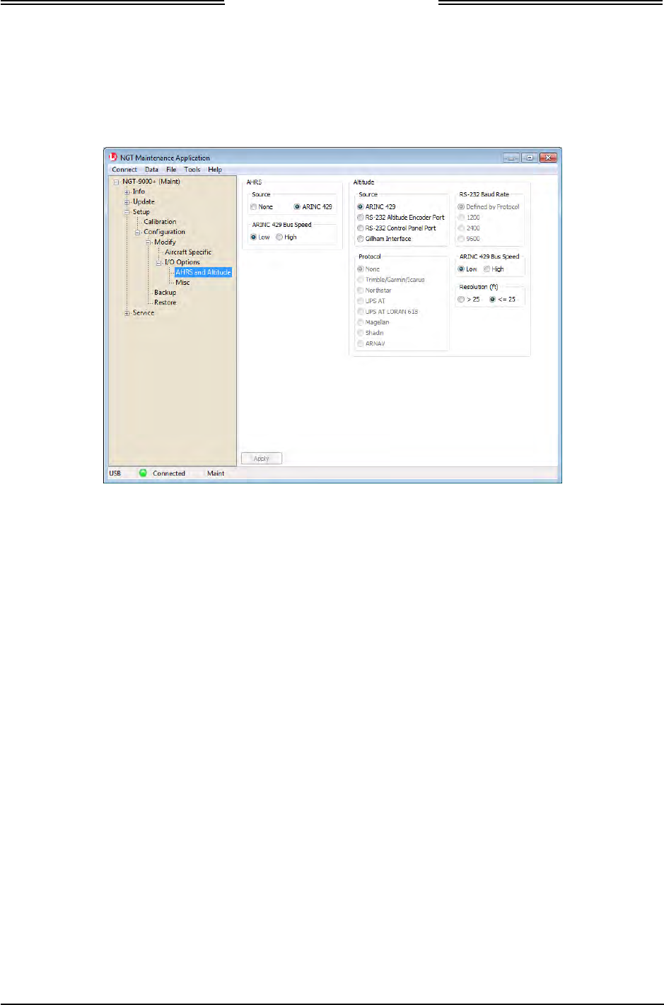
Lynx NGT-9000
Installation Manual
3.7.2 I/O Options – AHRS and Altitude
From the Lynx MAT select Setup Z Configuration Z Modify Z I/O Options Z AHRS and Altitude.
See Figure 3-10. Enter the information specific to the installation for the intended certification.
Figure 3-10: Lynx MAT – I/O Options – AHRS and Altitude
1. AHRS
a. Source: Select None or ARINC 429.
b. ARINC 429 Bus Speed: If the source selected is ARINC 429 select Low (12.0 to 14.5 Kbps) or
High (100 kbps) bus speed.
2. Altitude
a. Source: Select from one of the following:
• ARINC 429
• RS-232 Altitude Encoder Port
• RS-232 Control Panel Port
• Gilham Interface
b. Protocol: These options are available only when the selected source is “RS-232 Altitude
Encoder Port”.
c. RS-232 Baud Rate: These options are available only when the selected source is “RS-232
Altitude Encoder Port” or “RS-232 Control Panel Port”.
d. ARINC 429 Bus Speed: If the source selected is ARINC 429 select Low (12.0 to 14.5 Kbps) or
High (100 kbps) bus speed.
e. Resolution (ft): Select >25 or <=25 based on the encoder increment rate.
3. Click on the Apply button after all information is entered. This information is saved to the
configuration module.
0040-17001-01 Installation Checkout Page 3-13
Revision A January 15, 2015
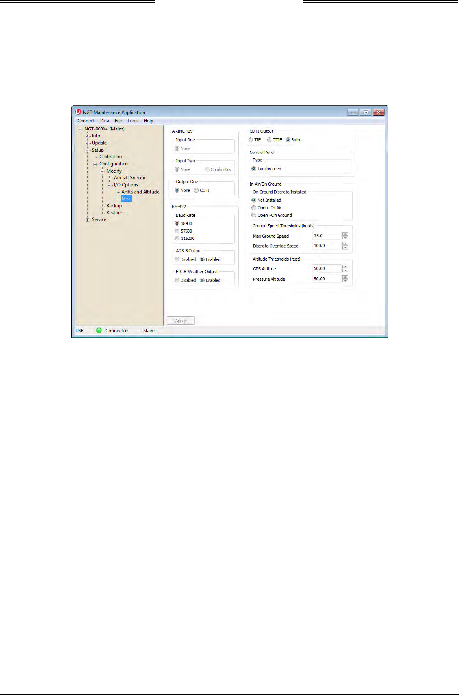
Lynx NGT-9000
Installation Manual
3.7.3 I/O Options – Misc
From the Lynx MAT select Setup…Configuration Z Modify Z I/O Options Z Misc. See Figure 3-11.
Enter the information specific to the installation for the intended certification.
Figure 3-11: Lynx MAT – I/O Options – Misc
1. ARINC 429: Set up the ARINC Input and Output bus using the following:
a. Input One: None.
b. Input Two: None.
c. Output One: Select either None or CDTI. Selecting CDTI sets the ARINC 429 Output to
transmit traffic data from the unit to an approved traffic display.
2. RS-422: Set up the RS-422 interface as follows:
a. Baud Rate: Select a baud rate appropriate to the equipment connected via the RS-422 bus.
b. ADS-B Output: This option enables or disables output of traffic on the RS-422 output bus.
Note: Must be enabled for RS-232 WiFi option.
c. FIS-B Weather Output: This option enables or disables output of weather on the RS-422
output bus. Note: Must be enabled for RS-232 WiFi option.
3. CDTI Output: This option enables or disables output of TIF or DTIF data to a CDTI ARINC 429
interface.
4. Control Panel: Only one choice (Touch screen) is available.
Page 3-14 Installation Checkout 0040-17001-01
January 15, 2015 Revision A

Lynx NGT-9000
Installation Manual
5. In Air / On Ground
The following options are setup based on the emitter category selected (aircraft type) and the In Air / On
Ground selections.
• A fixed wing aircraft with a ground discrete installed requires the following options: “Max Ground
Speed” and “Discrete Override Speed”.
• A fixed wing without discrete requires the following options: “Max Ground Speed”, “GPS Altitude”,
and “Pressure Altitude”.
• A rotorcraft with discrete requires the following option: “Max Ground Speed”.
• A rotorcraft without discrete requires the following options: “Max Ground Speed”, “GPS Altitude”,
and “Pressure Altitude”.
a. On Ground Discrete Installed: This is the WOW input, Discrete 3 input. See J1 Pin 29.
• Not Installed
• Open – Ground on Ground
• Open – On Ground
b. Ground Speed Thresholds (knots)
• Max Ground Speed: The valid range is 30 to 100. Typically 70% of Vs0. Must be less
than or equal to the Discrete Override Speed.
This is the upper threshold speed which aircraft is considered on ground. Ground speeds
below this level place the unit in the Ground state. Fields that become inhibited get set to
zeros. As fields become uninhibited the values are reset to defaults.
• Discrete Override Speed: Applicable only when On Ground Discrete installed and not a
Rotorcraft. When applicable, the valid range is 30 to 100, typically 130% of Vs1, and
must be greater than or equal to Max Ground Speed.
This is the lower threshold speed which aircraft is considered in air. Ground speeds above
this level place the unit in the In Air state, overriding the discrete switch.
c. Altitude Thresholds (feet)
• GPS Altitude: The valid range is 0 to 500.
This value is used for fixed wing and rotorcraft installs that do not have an air/ground
discrete. This is the lower limit threshold difference in GPS altitude after Power ON at
which aircraft is considered in air. A change in GPS altitude above this level places the
unit in the In Air state.
• Pressure Altitude: The valid range is 0 to 500.
This value is used for fixed wing and rotorcraft installs that do not have an air/ground
discrete. This is the lower limit threshold difference in pressure altitude after Power ON at
which aircraft is considered in air. A change in pressure altitude above this level places the
unit in the In Air state.
6. Click on the Apply button after all information is entered. This information is saved to the
configuration module.
0040-17001-01 Installation Checkout Page 3-15
Revision A January 15, 2015
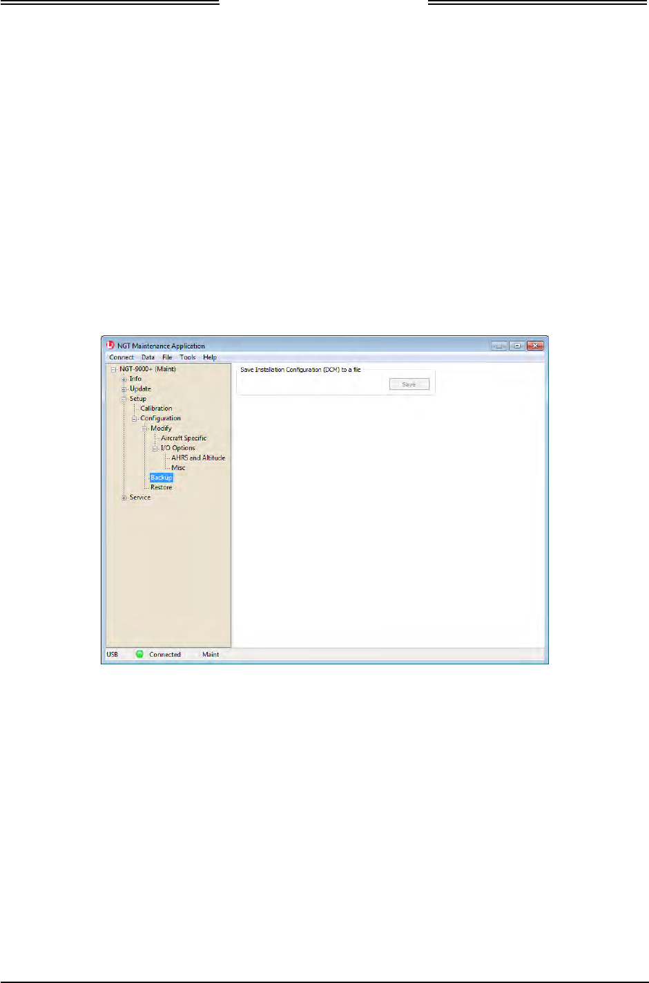
Lynx NGT-9000
Installation Manual
3.7.4 Backup
Use this feature to save configuration settings to a file to be used later or as a backup. The procedure to
1. From the Lynx MAT select SetupZ ConfigurationZ Backup.
• The MPC attempts to load DCM data, if it is not already loaded, when this screen is entered.
2. Click “Save” to copy the configuration information to a file on the MPC. See Figure 3-12.
• If operation worked... status bar indicates: "Save of DCM succeeded"
• If the DCM data is not loaded after the Save button is pressed a message is shown on the screen
to indicate this. Instructions are given on how to attempt to get the data loaded. If MAINT mode
cannot be entered, then cycle power to the unit and try again.
• After saving these settings, the file acquired can then be used to restore an aircraft’s
configuration settings later. The restore command instructions are found in section 4.4.3 of this
document.
Figure 3-12: Lynx MAT – Configuration - Backup
Page 3-16 Installation Checkout 0040-17001-01
January 15, 2015 Revision A
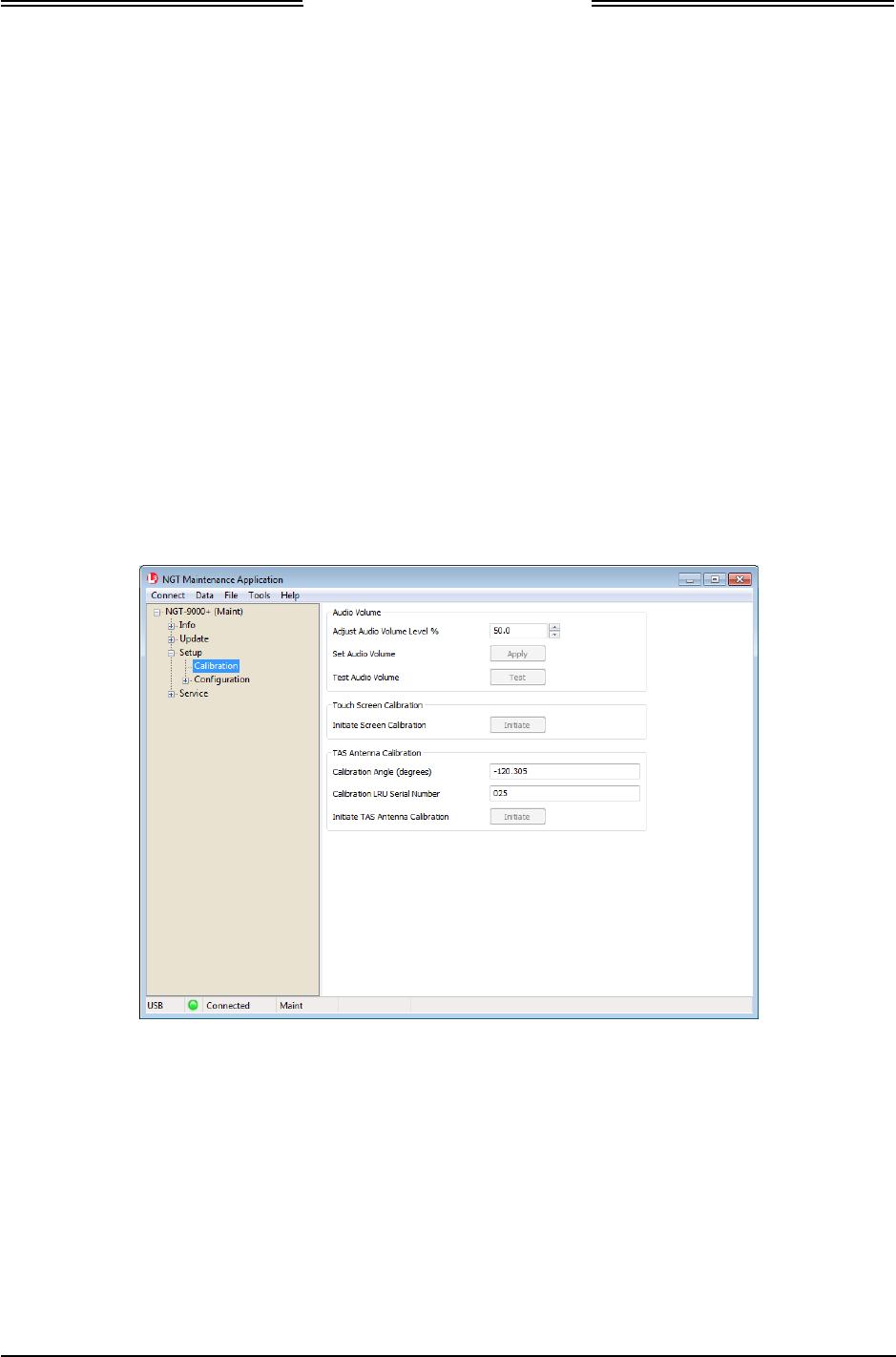
Lynx NGT-9000
Installation Manual
3.8 CALIBRATION SETUP
This procedure is used to calibrate the unit and must be completed prior to performing the Installation
Checkout for first time installations. The Log Sheet provided in Appendix C should be filled out during
this procedure and maintained with the aircrafts permanent records.
These procedures assume the following:
• Power is being supplied to the aircraft and the unit.
• The Lynx MAT is active on the MPC.
• The MPC is connected to the unit via the USB interface
• The MPC and unit are communicating.
3.8.1 Audio Calibration and Test
1. From the Lynx MAT select SetupZCalibration. See Figure 3-13.
2. Set the Audio Volume Level % and click on the Apply button.
3. Click “Test” to listen to the audio level selected.
4. Repeat step 2 and 3 until audio volume is set to the level desired.
• The audio test may need evaluation with both low and high cockpit noise present.
Figure 3-13: Lynx MAT – Setup - Calibration
3.8.2 Screen Calibration
When performing this calibration the user must be as accurate as possible. For best results a stylus is
recommended.
1. From the Lynx MAT select SetupZCalibration.
2. Press the Initiate button within the “touch Screen Calibration” box on the Lynx MAT and observe
that the maintenance screen on the unit is showing the calibration screen.
3. In the Calibration screen touch and release each target shown. (Four calibration targets and two
verification targets). Each target must be touched within 15 seconds of the last touch or a Calibration
Timeout message is shown. The unit returns to the main screen.
0040-17001-01 Installation Checkout Page 3-17
Revision A January 15, 2015
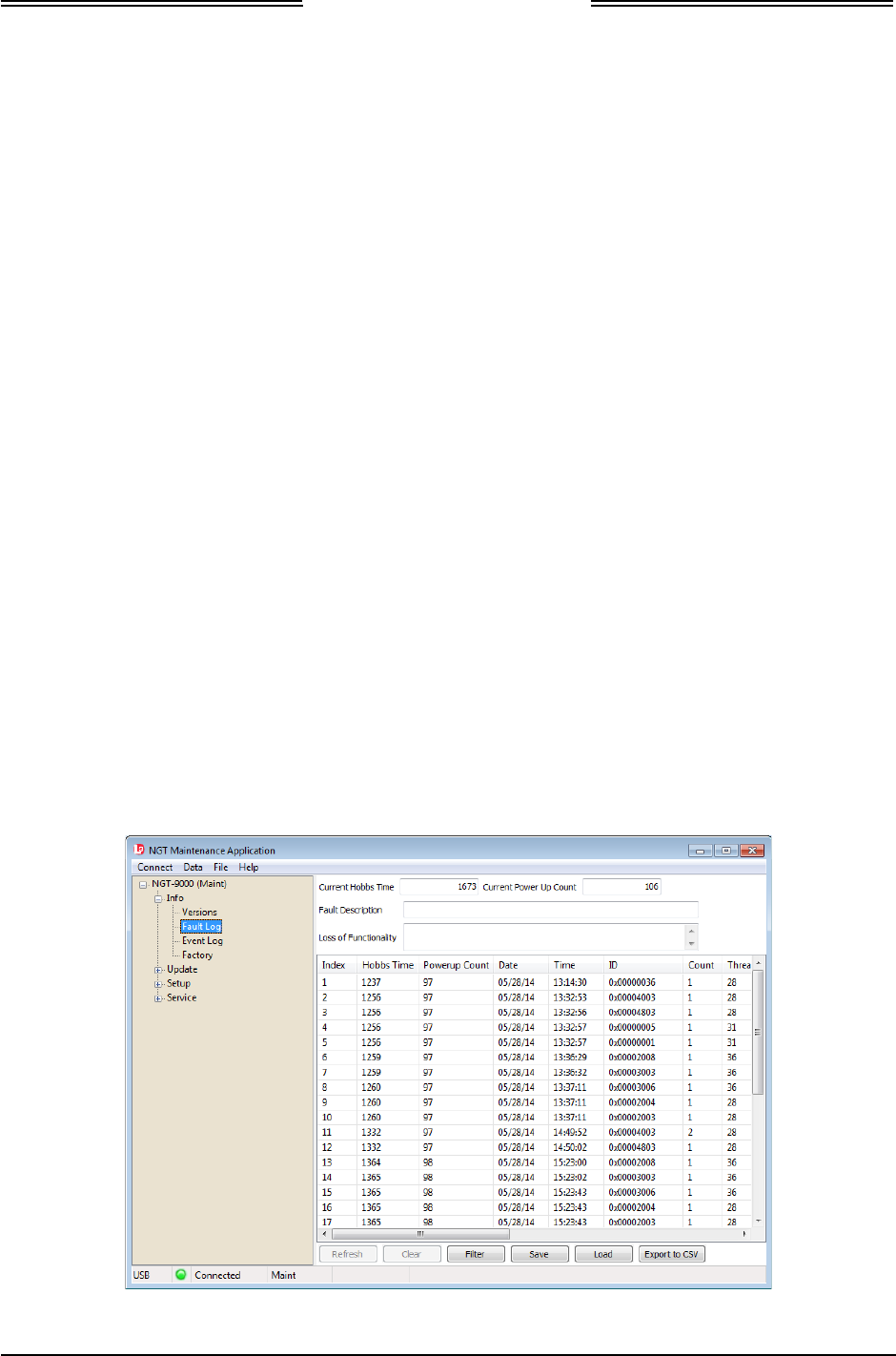
Lynx NGT-9000
Installation Manual
3.8.3 TAS Antenna Calibration
This calibration is available only if the Lynx NGT-9000s with TAS option is installed and the TAS option
is selected in the aircraft specific options.
1. From the Lynx MAT select SetupZCalibration.
2. Press the Initiate button within the TAS Antenna Calibration box to activate the TAS antenna cal at
the next Operational Mode startup.
• A dialog window is shown stating “The request succeeded and the calibration will be performed
on the next boot of operational software”.
3. Restart the unit by selecting Service Z Restart Unit Mode in Operational Software Mode.
4. When the unit is calibrating in normal operation the message “Calibrating Antenna” is shown on the
traffic application screen (right side).
• If the calibration passes, the LRU serial number (obtained from the factory configuration) and
calibration angle is written into the configuration module for subsequent use.
• If calibration fails, then the message “Calibration Failed” is shown on the traffic application
screen for a short duration. The system continues to try to calibrate the antenna once each boot
until it is successful.
Refer to the troubleshooting information in the maintenance section if the TAS continues to fail.
A TAS fail will also be shown on the message screen. The MSG button does not appear on the
screen until after 2 minutes of the unit being in normal operation.
3.8.4 Clear Fault Log
It is recommended that the fault log be cleared after completion of installation and service.
1. Clear the fault log from the Lynx MAT by selecting Info Z Fault Log See Figure 3-14.
2. Select Clear button.
3. Answer “Yes” to confirmation dialogs.
4. Cycle power to the unit.
5. The calibration and configuration setup is complete.
Figure 3-14: Lynx MAT – Info – Fault Log
Page 3-18 Installation Checkout 0040-17001-01
January 15, 2015 Revision A
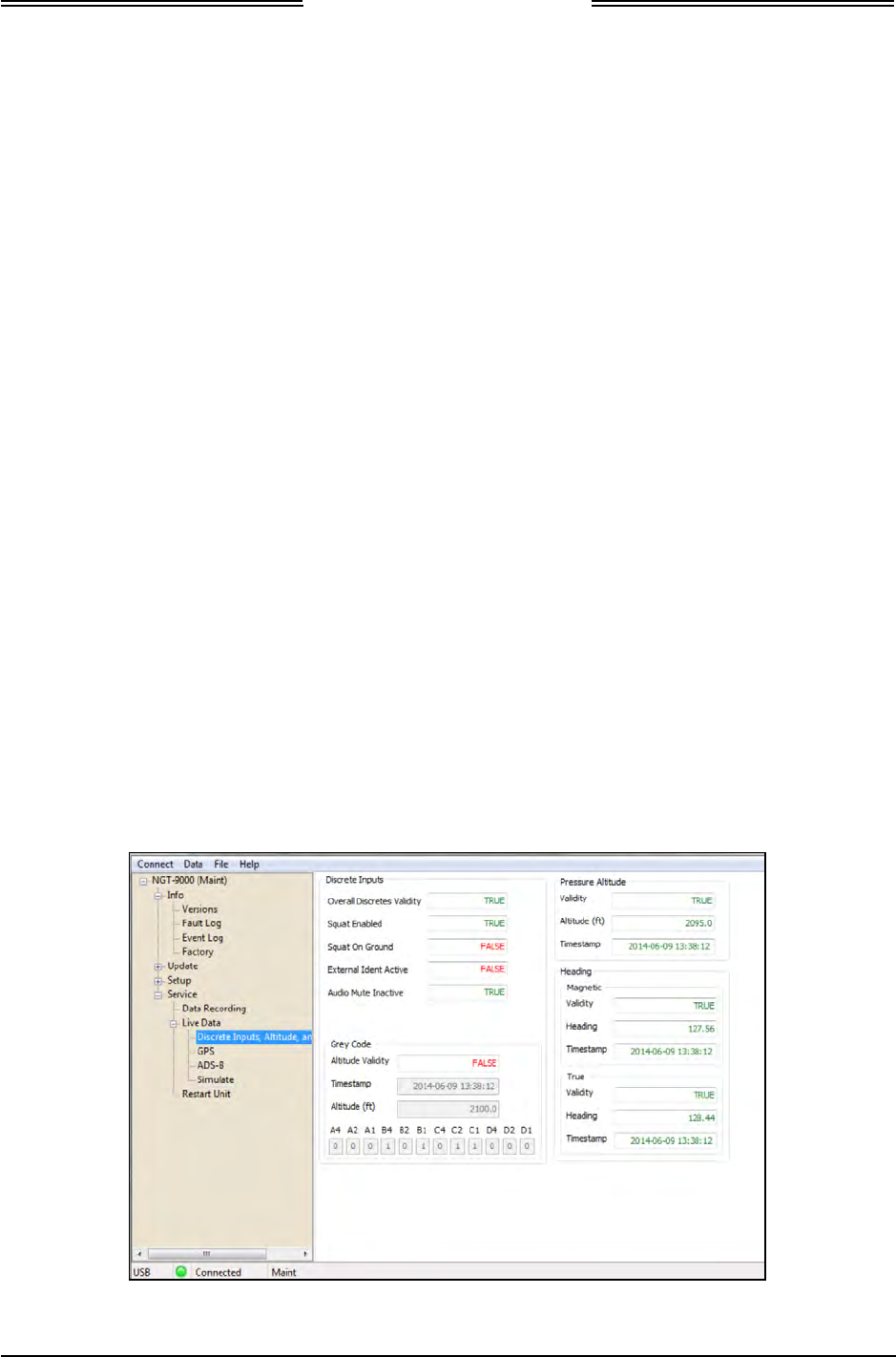
Lynx NGT-9000
Installation Manual
3.9 INTERFACE CHECK
Use this procedure to check input and output signals. These procedures assume the following:
• Power is being supplied to the aircraft and the unit.
• The Lynx MAT is active on the MPC.
• The MPC is connected to the unit via the USB interface
• After configuration options and calibration procedures where completed, power has been cycled to
the unit.
• The MPC and unit are communicating and the Lynx MAT has been restarted the unit in Maintenance
(no WiFi).
3.9.1 Live Data - Discrete Inputs, Altitude, and Heading
1. From the Lynx MAT select ServiceZLive DataZDiscrete Inputs, Altitude, and Heading. An
example of this page is shown in Figure 3-15.
• Review the information seen on the inputs page.
• The True/False indication of the current state of the discrete (e.g. True for the squat on ground
means that the aircraft is on ground. A false would mean that the aircraft was not on the ground,
at least according to the discrete).
Note – When the audio mute discrete is grounded it is considered active (i.e. muted). The Audio
Mute Inactive indication shows “True” when this discrete is active (grounded).
• The Overall Discretes Validity is an indication of the remaining discrete states. A “True”
indicating that these indications are valid. A “False” indication with red text indicates that the
input is not being detected by the unit and a problem exists. If a problem is noted do the
following.
o Check the configuration setup options for correct settings.
o Check the fault log (InfoZFault Log) for issues.
o Check wiring or equipment.
• Compare the altitude and heading values to an outside source.
Figure 3-15: Lynx MAT – Live Data - Inputs
0040-17001-01 Installation Checkout Page 3-19
Revision A January 15, 2015
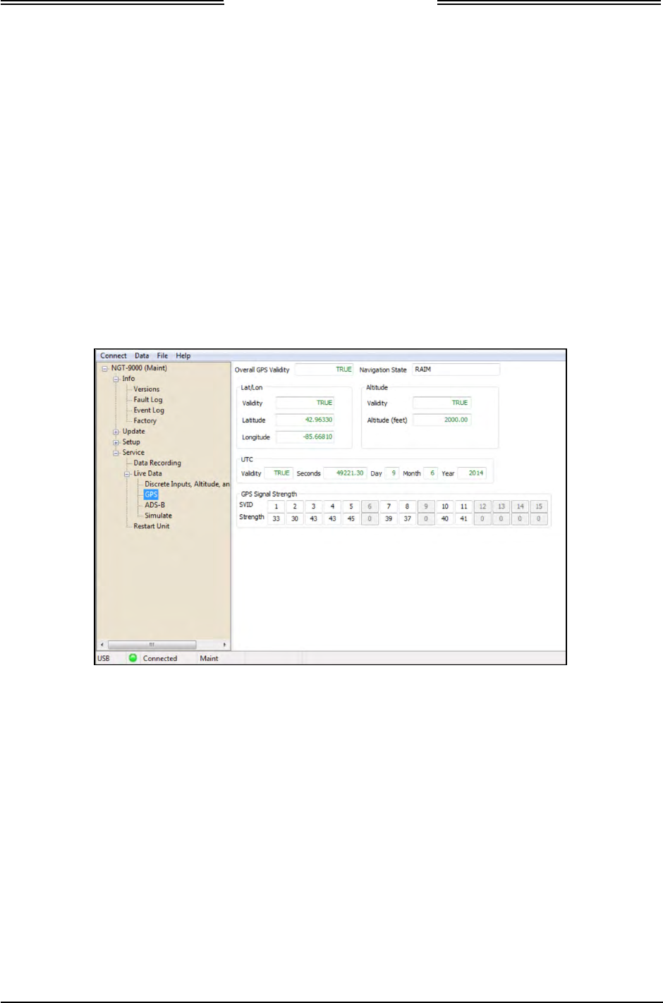
Lynx NGT-9000
Installation Manual
3.9.2 Live Data - GPS
1. From the Lynx MAT select ServiceZLive DataZGPS. An example of this page is shown in Figure
3-16.
2. Observe that the GPS data is being received.
3. If data is being received verify that the Day, Month, and Year data is correct.
• Observe that the GPS data is being received and signal strength is within 30 to 50 db. Note – the
Navigation State always shows “RAIM” even though the device is actually in WAAS mode.
4. If data is not being received do the following:
• The GPS signal may be blocked; move the aircraft to an open environment or input a GPS
signal using test equipment.
• Check the fault log (InfoZFault Log) for issues.
• Check wiring or GPS antenna for installation issues.
Figure 3-16: Lynx MAT – Live Data - GPS
Page 3-20 Installation Checkout 0040-17001-01
January 15, 2015 Revision A
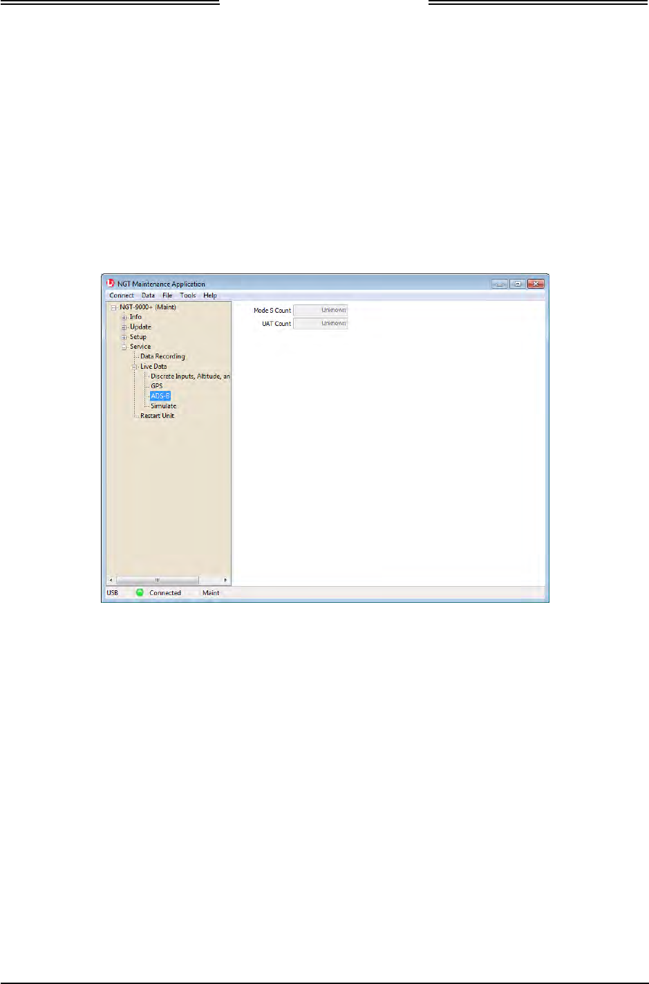
Lynx NGT-9000
Installation Manual
3.9.3 Live Data – ADS-B
1. From the Lynx MAT select ServiceZLive DataZADS-B. An example of this page is shown in
Figure 3-17.
2. Observe that both data fields are showing a count tally of received messages (A zero is a valid
number if the unit is not in range of a signal). If data is not being received do the following:
• The signal may be blocked; move the aircraft to an open environment or input a signal using
test equipment.
• Check the fault log (InfoZFault Log) for issues.
3. Check wiring or antenna for installation issues.
Figure 3-17: Lynx MAT – Live Data - GPS
0040-17001-01 Installation Checkout Page 3-21
Revision A January 15, 2015

Lynx NGT-9000
Installation Manual
3.9.4 Live Data – Simulate
1. From the Lynx MAT select ServiceZLive DataZSimulate. An example of this page is shown in
Figure 3-18.
2. Check the following. Perform only the checks necessary for the installation.
• Click either simulated “ground” or “open” (per the installation – typically ground activates the
lamp) from the ADS-B Out inoperative to check the ADS-B Out Fail lamp is working correctly.
Click “Not simulating” to remove simulated data.
• Setup a cockpit audio signal. Click either simulated “ground” or “open” (per the installation –
typically ground mutes the signal) from the Audio Mute Out to check the Audio Mute is working
correctly. Click “Not simulating” to remove simulated data.
• Click either simulated “ground” or “open” (per the installation– typically ground activates the
lamp) from the Traffic Alert to check the Traffic Alert lamp is working correctly. Click “Not
simulating” to remove simulated data.
Figure 3-18: Lynx MAT – Live Data - Simulate
3.9.5 Configuration Check Complete
1. If needed, clear the fault log from the Lynx MAT by selecting Info Z Fault Log and selecting the
Clear button. See Figure 3-14.
2. Disconnect the MPC from the unit.
3. Cycle power to the unit.
4. Proceed to the Installation Checkout procedure paragraph 3.10.
Page 3-22 Installation Checkout 0040-17001-01
January 15, 2015 Revision A

Lynx NGT-9000
Installation Manual
3.10 INSTALLATION CHECKOUT
This procedure validates the installation, calibration, and configuration setup of the Lynx NGT-9000s and
secondary equipment. Installers are advised to read through the entire procedure and ensure all the
necessary tool, equipment, and data are available before performing the checkout.
Take the following into consideration prior to installation.
• Perform the installation checkout procedure with aircraft on ground.
• Perform only those checks that are applicable to the installation.
• To conserve aircraft battery power, it is recommended that the aircraft be connected to an external
aircraft power source during installation and checkout.
• An IFR-6000 (or equivalent) Ramp Test Set is required with the UAT option installed. These checks
assume familiarity with the set up and operation of the ramp test set.
• All test equipment shall be calibrated in accordance with the manufacturer’s recommendations.
• If the ADS-B Out Fail lamp is installed it flashes ON/OFF while the unit is starting and GPS is
initializing (acquiring signal).
• It is normal for the TIS-B Out Of Coverage lamp to be ON during checkout if there is not a ground
station or signal within range.
3.10.1 Functional Checks
Use the following procedure to check that the Lynx NGT-9000s (the unit) and secondary equipment is
operating properly.
3.10.1.1 WiFi Check
This check required only if the WiFi option is installed and requires a WiFi accessory connected to the
wiring harness. The PED requires an approved APP be installed.
NOTE
This check requires a valid signal (ADS-B In with TIS-B and/or FIS-B service).
It is also possible to use an IFR-6000 set up and simulate the information.
1. The PED, unit WiFi interface, and WiFi Dongle must be configured.
2. Verify that the PED is receiving data from the unit and that traffic and weather (if available) data is
being displayed.
3.10.1.2 System Status Check
Use the following procedure to check equipment interfaces and operation of the unit.
1. Apply power to the unit.
• Initialization and self-tests begin.
2. The splash screen is displayed in less than 5 seconds. See Figure 3-19.
• The company name/Logo is shown on the left side and the product name on the right.
0040-17001-01 Installation Checkout Page 3-23
Revision A January 15, 2015
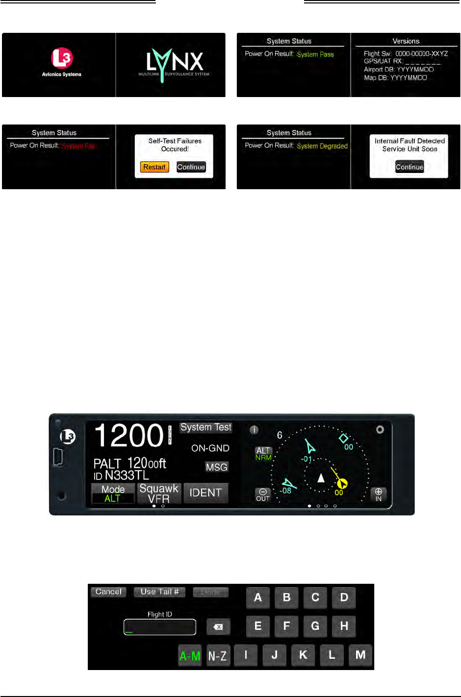
Lynx NGT-9000
Installation Manual
Splash Screen System Status (Passed) and Versions
System Status (Failed) System Status (Degraded)
Figure 3-19: Examples of Start-up Screens
3. The System Status is shown on the left side in less than 20 seconds
• If System Status is “System Pass”, then the Versions screen is shown on the right of the display.
The version screen identifies software and database information currently loaded on the unit.
Verify that the information is correct for this installation.
• If System Status is “System Fail”, then the message “Self-Test Failures Occurred” is shown on
the right side of the display. The option to restart the unit or to continue start up in a degraded
mode is shown on the right side of the display. Press the Restart or Continue button to proceed.
• If System Status is “System Degraded”, then the message “Internal Fault Detected Service Unit
Soon” is shown on the right side of the display. Press the Continue button to proceed.
4. When normal operation begins the left screen shows the Transponder Application screen and the
right screen shows the Traffic screen. See Figure 3-20.
Figure 3-20: Example of Normal Operation
• If configured the Flight ID Screen is shown before the normal operation screen is shown See
Figure 3-21.
Figure 3-21: Example of Flight ID Input Screen
Page 3-24 Installation Checkout 0040-17001-01
January 15, 2015 Revision A
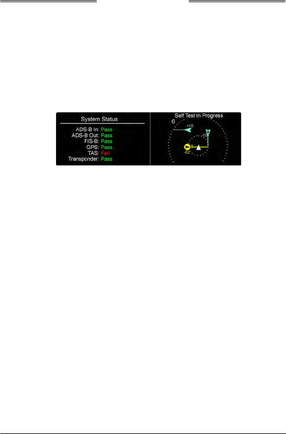
Lynx NGT-9000
Installation Manual
5. Press the System Test button located on the left screen. See Figure 3-22. The system test is used to
check the operation of external data inputs.
6. During the System Test the user functions are disabled and the right screen shows a preset traffic
display with the message “Self Test In Progress” at the top of the screen. See Figure 3-22. The left
screen shows the test results of the functional areas indicated and not specific test failures.
NOTE
Functions that are not part of the installation are not shown.
Figure 3-22: Example of System Test Results
7. The unit returns to normal operation if no failures are detected and a “System Test Pass” message is
heard through the aircraft audio system.
• If a “Fail” or External Fail” is shown for any of the system functions, then the message “Self-
Test Failure” is shown on the right side of the display (and is heard through the aircraft audio
system) as well as the option to restart the unit or to continue start up in a degraded mode. Press
the “Restart” button and perform the System Test again. If the failures continue press the
“Continue” button to proceed.
• If “Degraded” is shown for any of the system functions, then the message “Service Unit Soon”
is shown on the right side of the display (and is heard through the aircraft audio system). Press
Continue screen button to proceed.
8. Correct failures before going any further with the functional check.
• A “Fail” indicates an internal unit error. Refer to the fault isolation information provided in the
maintenance manual for detailed information.
• An “External Fail” indicates an external signal loss. Check antenna and data source signals and
connections. Refer to the fault isolation information provided in the maintenance manual for
detailed information.
• Press the “MSG” button located on the Transponder Application screen to view fail messages.
The messages “No TIS-B / ADS-R Coverage” or” FIS-B No Signal” may be seen due to the
unit being out of range of a ground station. This is normal and the checks may proceed.
• If the problem is persistent it may be necessary to connect the MPC and use the Lynx MAT to
view live data, see paragraph 3.9 for details.
0040-17001-01 Installation Checkout Page 3-25
Revision A January 15, 2015

Lynx NGT-9000
Installation Manual
3.10.1.3 Options Screen
1. Press the gear shaped “Options” button located at the top right of the traffic screen. See Figure 3-23.
2. Press the Done button when the checks below are complete.
Status Settings Brightness
Figure 3-23: Options Screen…
3.10.1.3.1 GPS Operation Check
1. Press the Status button to open the GPS Status screen.
2. Verify that GPS information is being displayed and that the “GPS” operating mode is “WAAS”. If
the information is missing perform the following:
• The unit may not be able to establish communication with a satellite due to an obstruction of the
GPS reception. Either move the aircraft to an area with better GPS reception or use a GPS
Simulator to generate the necessary signal.
• If the GPS reception continues to be a problem, check the GPS antenna installation.
3. Verify that the GPS position agrees with a known reference point.
4. Verify that the signal bars are showing at least 40 -50% in the GPS Receiver Information Packet for
all the GPS/SBAS satellites in view.
5. Turn ON other avionics and verify that the signal bars are showing at least 40 -50% in the GPS
Receiver Information Packet for the satellites do not degrade significantly and position remains steady.
6. Turn ON VHF Com radios and verify that the signal bars are showing at least 40 -50% in the GPS
Receiver Information Packet for the satellites do not degrade significantly and position remains
steady.
7. If the aircraft is TAS/TCAS equipped, turn on the TAS/TCAS system and verify that the signal bars
are showing at least 40 -50% in the GPS Receiver Information Packet for the satellites do not
degrade significantly and position remains steady.
8. Any GPS interference (significant degrade in signal strength) must be resolved prior to completing
the installation. Use the troubleshooting procedures in the maintenance section for help.
3.10.1.3.2 Initial Traffic Altitude Mode
1. Press the Settings button.
2. Verify that unrestricted traffic Altitude Mode annunciator is green. Change the setting if needed by
pressing the indicator about the unrestricted text. Note - This is how the pilot selections the default
traffic altitude filter mode.
Page 3-26 Installation Checkout 0040-17001-01
January 15, 2015 Revision A

Lynx NGT-9000
Installation Manual
3.10.1.3.3 Set Display Brightness
1. Press the BRT button located on the right side of the screen to open the brightness scale bar.
2. Press and slide the scale button to adjust the Display Brightness Trim to the desired percentage.
3. The brightness screen times out after a few moments returning to the settings screen.
3.10.1.4 Indicator Lamp Check
Verify the following indicator lamps functioning properly (if installed) during the checkout.
• TAS Alert
• ADS-B Out Fail
• TIS-B Not In Coverage
1. If an annunciator dimming switch was installed, verify all annunciators are illuminated full bright
when BRT is selected.
2. Verify all annunciators are illuminated at the desired dimming level when DIM is selected.
3. TAS Alert – This lamp is ON when a TA (Traffic Advisory) is detected by the TAS system. Verify
the operation of this lamp when performing tests for the TAS system.
4. ADS-B Out Fail – This lamp does the following depending on the situation:
• Flashes at a slow rate (1 sec On and 1 sec Off) while the GPS is initializing. Check by cycling
power to the unit. Flashing will last only 2 minutes before the lamp stays ON.
• The lamp is ON when the ADS-B Out has failed.
5. TIS-B Not In Coverage – This lamp is ON if no ground station signals (TIS-B/ADS-R) is detected.
The lamp is OFF when a signal is detected either by a ground station or when the IFR-6000 is used
for TIS-B checks.
Note: It is normal that this light will NOT extinguished when testing with an IFR-6000. It will only
extinguish when within coverage of a ground station.
3.10.1.5 Discrete Switch Checks
Verify the following external switches are functioning properly (if installed). Note: The MPC can be
used to validate the inputs for the external checks. See paragraph 3.9 for details.
1. If installed verify that the Audio Mute switch inhibits audio messages sent by the unit.
2. Verify that the IDENT Input switch causes the unit transponder to transmit the "ident" flag in
transponder interrogation replies. This check may be skipped if verified during the configuration
setup procedure.
3. The On-Ground switch function is verified by the operation of the System Test button is available on
the Transponder Application screen and the ON-GND message located on the transponder screen.
3.10.1.6 Suppression Pulse Check
This check is optional. Use an oscilloscope to verify that the RF Suppression pulse (Discrete #2 out) is
100 µs ±5µs, +28 V dc when the unit is transmitting TAS data. There are 2 other lengths of suppression
pulses that will be seen when the transponder is operating (1 longer and 1 shorter than 100us).
3.10.1.7 Alternate Display Check
The NGT-900 may be interfaced to a compatible traffic display (ARINC 429 or RS-422) and weather
display (RS-422). The instructions provided in this manual are generic. Refer to the manufacturers display
manual for operation and checkout procedures.
• A functional check with the NGT-9000 is accomplished during the check of the ADS-B In, TIS-B,
FIS-B and any other checks requiring the use of the alternate display.
0040-17001-01 Installation Checkout Page 3-27
Revision A January 15, 2015
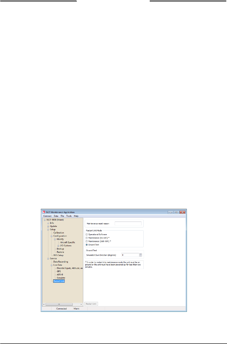
Lynx NGT-9000
Installation Manual
3.10.2 Ground Checks
Perform only those checks that are applicable to the installation. An IFR-6000 (or equivalent) Ramp Test
Set is required.
NOTES
1. These checks assume familiarity with the set up and operation of
the ramp test set.
2. All test equipment used in completing these tests shall be
calibrated in accordance with the manufacturer’s
recommendations.
3.10.2.1 Ground Test Mode
Placing the unit in the Ground Test Mode does the following:
• Simulation of heading or track (pointing the traffic on the screen in the correct orientation).
• Sets the unit to “In-Air” status allowing Mode C (altitude) output and additional ADS-B output
messages (sent at a higher rate).
o In-Air status also allows Mode A (i.e. squawk code). While on-ground, both Mode A and C
replies are inhibited.
o This allows the IFR-6000 to test the encoding altimeter input (mode C).
These procedures assume the following:
• Power is being supplied to the aircraft and the unit.
• The Lynx MAT is active on the MPC.
• The MPC is connected to the unit via the USB interface
• The MPC and unit are communicating. From the Lynx MAT panel select
ConnectZNGT9000ZUSB. This is required each time power is cycled.
1. From the Lynx MAT panel select ServiceZRestart Unit. See Figure 3-24.
Figure 3-24: Lynx MAT – Ground Test
Page 3-28 Installation Checkout 0040-17001-01
January 15, 2015 Revision A

Lynx NGT-9000
Installation Manual
2. If heading is not being input to the Lynx NGT-9000, then select Ground Test and enter a Simulated
Own Direction (0 – 359 deg.). The own direction is the current true heading of the aircraft A unit
with a heading input can ignore this step.
NOTE
When entering heading information into the IFR-6000 UUT HDG entry
field make sure to enter either the same simulated heading as was entered
into the Lynx MAT own direction field or the actual aircraft heading (true
heading) as appropriate.
3. Click on the Restart Unit button.
4. The unit starts up in normal operation, but an amber “Ground Test” message is shown below the
options button on the right side of the display.
• Cycling power at anytime takes the unit out of Ground Test Mode. (Note: Ground Test Mode is
automatically, without cycling power, exited if aircraft flight is detected).)
5. Continue with the checkout procedures below.
3.10.2.2 Altitude Check
1. Perform the altitude check per 14 CFR Part 91.411 and 14 CFR Part 43 Appendix E & F.
2. Verify that the displayed altitudes of the unit and the primary display (PFD) or equivalent instrument
are within the required range shown below (per the installation):
• Gilham Code altitude source the range is +/- 100 ft.
• Other altitude source the range is +/- 25 ft.
3.10.2.3 Transponder Output Check
Verify that the Transponder test performed by the test set is successful and that the test set is receiving the
correct transponder information (i.e. Mode S Identifier, Flight ID, etc). This check requires an IFR-6000
(or equivalent) Ramp Test Set and the Lynx MAT.
1. Set ground test (in air) mode (see para. 3.10.2.1) on NGT-9000 using Lynx MAT.
2. Enter the XPDR setup page of the IFR-6000 and ensure that the antenna/cable loss setup is correct.
3. Run the Generic Mode S test and verify “PASS” (in air).
• The IFR-6000 must be located in the nominal position or the power/frequency test may fail.
4. Set NGT-9000 normal mode (on ground) using the Lynx MAT (restart unit in operational software
mode) or cycling power to the NGT-9000.
5. Run Generic Mode S test using the IFR-6000. Verify that a “PASS” is shown at the top of the IFR-
6000 on-ground results page.
• It may be necessary to manually enter the aircraft’s ICAO code in the XPDR setup page of the
IFR-6000 when the NGT-9000 is in normal mode (on ground).
3.10.2.4 ADS-B Out Check
Before performing this check ensure that the GPS position on the NGT-9000 is acquired. If installed the
ADS-B Out Fail lamp is OFF, and the external display/PED is ON (if installed).
1. From the ADS-B/GICB/UAT screen on the IFR-6000, select ADS-B MON ADS-B.
2. Verify that the ADS-B Out test performed by the test set is successful.
3. Ensure correct AA (Aircraft Address) in HEX and OCTAL.
0040-17001-01 Installation Checkout Page 3-29
Revision A January 15, 2015

Lynx NGT-9000
Installation Manual
3.10.2.5 ADS-B In Check
Before performing this check ensure that the GPS position on the NGT-9000 is acquired, and that the
NGT-9000 is in Ground Test mode (in air). If installed, the ADS-B Out Fail lamp is OFF. Perform the
ADS-B In check using an IFR-6000 (or equivalent) Ramp Test Set using the latest ADS-B update.
The test set simulates ADS-B intruders by manually defining a position over the earth. Intruding flight
parameters are programmed from the IFR-6000 screen.
1. From the ADS-B/GICB/UAT screen on the IFR-6000, select UAT, then GPS Status, and allow the
unit to acquire a GPS position (GPS SYNC).
2. Verify 978 MHz ADS-B In traffic information displayed on the unit with that being transmitted by the
test set.
a. From the ADS-B/GICB/UAT, select UAT, then UAT GEN, then ADS-B.
• Ensure targets are defined and UUT heading is equal to aircraft true heading.
• Ensure UUT LAT and UUT LON match aircraft’s present position.
• Select Run Test.
b. Observe that targets are showing on the display (s).
3. Verify 978 MHz TIS-B In traffic information display on the unit with that being transmitted by the test
set.
a. From the ADS-B/GICB/UAT screen on the IFR-6000, select UAT, then UAT GEN, then TIS-B.
• Ensure targets are defined and UUT heading is equal to aircraft true heading.
• Ensure UUT LAT and UUT LON match aircraft’s present position.
• Ensure TIS-B SITE ID is set to 1 (or any number between 1 and 15).
• Select Run Test
b. Observe that targets are showing on the display. A difference of 100ft between the test set data
and the displayed information is acceptable.
4. Verify 1090 MHz ADS-B In traffic information displayed on the unit with that being transmitted by
the test set.
a. From the ADS-B/GICB/UAT screen on the IFR-6000, select ADS-B GEN.
b. Enable at least item 1 - Airborne Position and item 4 - Airborne Velocity making sure the NACv
is set to a valid number (1 or greater).
• Enabling Item #3 - Ident & Cat makes it easy to determine that the target you have defined
is the one being displayed, especially if using a PED to double check.
• Ensure targets are defined and UUT heading is equal to aircraft true heading.
c. Observe that targets are showing on the display (s).
Page 3-30 Installation Checkout 0040-17001-01
January 15, 2015 Revision A

Lynx NGT-9000
Installation Manual
3.10.2.6 FIS-B Uplink Check
Before performing this check ensure that the GPS position on the NGT-9000 is acquired, and that the
NGT-9000 is in Ground Test mode (in air). If installed the ADS-B Out Fail lamp is OFF.
1. Perform the FIS-B check using the IFR-6000 (or equivalent) Ramp Test Set. The test set simulates
FIS-B ground base uplink (such as a METAR).
2. Set the unit to each of the FIS-B screens listed below and verify that information (such as a METAR).
is being displayed.
• FIS-B Graphic Application screen
• FIS-B Graphic Winds and Temp
• FIS-B Text data
3.10.2.7 TAS Traffic Check
Test required only for models with TAS. The TAS antenna calibration needs to be completed prior to this
test.
Before performing this check, ensure that the NGT-9000 is in Ground Test mode (in air).
1. Perform the TAS check using the IFR-6000 (or equivalent) Ramp Test Set. The test set simulates
TAS intruders by manually defining a scenario and can then verify the correct Traffic Advisories
have occurred on the unit. Intruding flight patterns are programmed from the IFR-6000 screen.
2. Verify that Traffic information displayed on the unit with that being transmitted by the test set.
3. Compare and verify the heading data transmitted by the test set is being displayed correctly on the
unit.
4. Verify audio alerts are being heard through the audio system. Adjustment of the audio volume may
be required. Refer to the configuration setup for instructions.
• Electromagnetic Interference (E.M.I.) Check
Check the following applicable aircraft systems, as well as any other system or device that is not listed,
for interference. Initial tests are to be conducted with the aircraft operating on external ground power.
Disregard any system or device that does not apply.
NOTE
The Electromagnetic Interference Check is required only for initial system
installations and not required if the unit is removed or replaced.
1. Communications
a. Cockpit Intercom
Using the cockpit intercom, verify interference free communications between the crew while
monitoring the effects of the unit.
0040-17001-01 Installation Checkout Page 3-31
Revision A January 15, 2015

Lynx NGT-9000
Installation Manual
b. VHF Communications
Set VHF communications radios to multiple frequencies and monitor effects of unit while
transmitting and receiving. At a minimum, the frequencies listed below should be tested, in
addition to locally available frequencies:
Check the GPS signal status of the each satellite being received does not drop while
transmitting each frequency for a period of 35 seconds. Degradation of individual received
satellite signals below a point where navigation is no longer possible is not acceptable and will
require that additional isolation measures be taken.
For installations on rotorcraft, ensure that the rotor blades do not interfere with the received GPS
signals. This problem has been experienced in some rotorcraft and varies with the rotation rate.
Test the following frequencies for 25 kHz COM channel spacing:
121.150 MHz 121.200 MHz 121.250 MHz 131.225 MHz 131.275 MHz 131.325 MHz
121.175 MHz 121.225 MHz 131.200 MHz 131.250 MHz 131.300 MHz 131.350 MHz
In addition test the following frequencies for VHF radios with 8.33 kHz channel spacing:
121.185 MHz 121.190 MHz 130.285 MHz 131.290 MHz
2. Navigation
a. VOR / ILS
Verify the operation of each VHF Nav receiver in both VOR and ILS modes (including
glideslope) while monitoring the effects of the unit.
b. DME
Verify the operation of each DME while monitoring the effects of the unit. The same
frequencies used for VOR and ILS testing may be used for this test.
c. Marker Beacon
Verify the operation of the Marker Beacon Receiver while monitoring the effects of the unit.
d. ADF
Verify the operation of the ADF receiver while monitoring the effects of the unit. Frequencies
from each band should be tested when possible. Public broadcast stations are acceptable for
conducting test.
3. Flight Director / Autopilot
Operate the flight director/autopilot system and verify it responds to commands from the flight
guidance panel while monitoring the effects of the unit.
4. Compass System
Verify each compass system is presenting correct information while monitoring the effects of the
unit.
5. Attitude System
Verify each attitude system is presenting correct information while monitoring the effects of the unit.
Page 3-32 Installation Checkout 0040-17001-01
January 15, 2015 Revision A

Lynx NGT-9000
Installation Manual
6. Safety Equipment
a. TAWS (If Installed)
Verify the function of the TAWS and Terrain Display while monitoring the effects of the unit.
b. Weather Monitoring System (If Installed)
Verify the function of the weather monitoring system while monitoring the effects of the unit.
• Display Check
1. Position the aircraft outside with an unobstructed view of the sky. Apply power to the unit and
supporting equipment.
2. Verify that system status has passed.
3. Verify that there are no new system messages, indicated by a blinking MSG button.
4. Verify that the Transponder Application (left screen) and the Traffic Application (right screen) are
providing data. Note – The data may be degraded until the GPS has acquired a position fix.
• Flight Test
It is recommended that a flight test be conducted after installation to verify proper operation of the Lynx
NGT-9000s system per the AML STC.
• Installation Checkout Complete
This completes the Checkout procedure.
0040-17001-01 Installation Checkout Page 3-33
Revision A January 15, 2015

Lynx NGT-9000
Installation Manual
This page intentionally blank
Page 3-34 Installation Checkout 0040-17001-01
January 15, 2015 Revision A

Lynx NGT-9000s
Installation Manual
Section
4
Maintenance
4.1 INTRODUCTION
This chapter contains general flightline maintenance and fault isolation procedures. Fault isolation is
intended to aid in identifying and correcting invalidities or isolating failures to a defective assembly.
4.2 CONTINUED AIRWORTHINESS
Regular maintenance of the Lynx NGT-9000s is not required except as included in this section and is to
be maintained on a “Condition Monitored” basis. Condition monitoring is based upon the following:
• Visual observation by the user.
• All units have unlimited service life, where service life is defined as that point in time when repair is
no longer economical.
The unit is subject to the following requirements:
• Title 14 CFR Part 91.411 (Altimeter)
• Title 14 CFR Part 91.413 (Transponder)
• Title 14 CFR Part 43 Appendix E & F
The Directional Antennas (NY156 or NY164) do not require scheduled maintenance or scheduled
overhaul and shall be maintained on a “Condition Monitored” basis.
4.3 PERIODIC MAINTENANCE
Perform the following at regular aircraft inspection intervals:
• Visually inspect for signs of corrosion.
• Visually Inspect for condition of wiring, shield terminations for proper grounding, routing, and
attachment/clamping.
• Visually inspect the unit mounting to the aircraft, verify visually that the screw heads are in full
contact with the mounting holes etc. Re-torque the screws if required.
• Check the display for cleanliness. The bezel, ambient light sensor, and display glass can be cleaned
with a damp lint-free, static-free cloth. If necessary, clean with a soft cloth moistened with a mild
solution of soap and water. Care should be taken to avoid scratching the surface of the display or
getting water inside the USB maintenance port. Do not spray cleaner directly on the screen.
• If the touch screen does not respond to a tap in the right location perform the screen calibration in
paragraph 4.3.1.
• It is recommended that an electrical bond check be performed between the unit and nearby exposed
portion of the aircraft metallic structure and verify that the measured value is less than or equal to 2.5
milliohms.
In the event of bonding check failure, remove the unit and clean it and its mounting holes at both the
unit and the aircraft structure and reattach the unit. Re-verify the resistance between the unit and
nearby exposed portion of aircraft metallic structure, and ensure it is less than or equal to 2.5
milliohms.
0040-17001-01 Maintenance Page 4-1
Revision A January 15, 2015
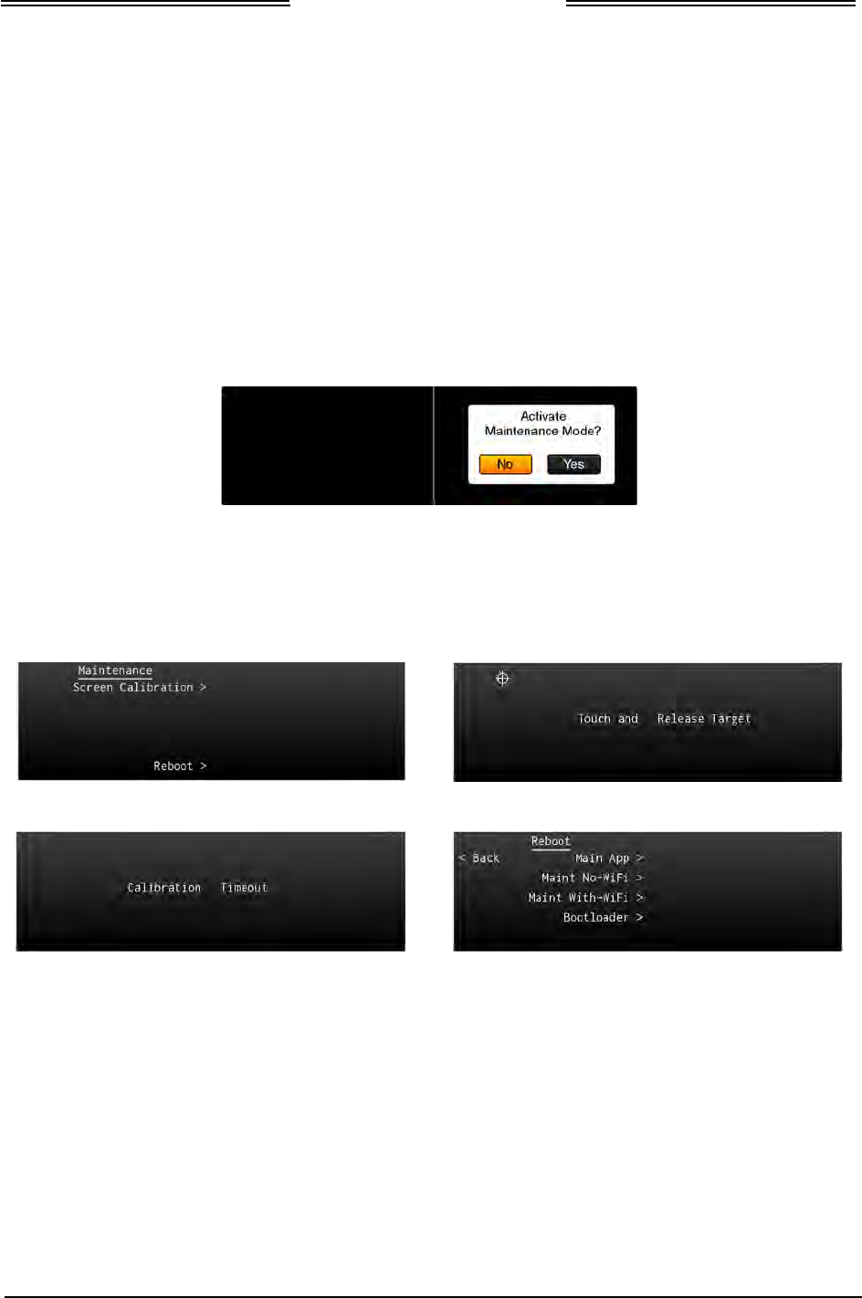
Lynx NGT-9000s
Installation Manual
4.3.1 Screen Calibration
Use this procedure to calibrate the touch screen for more accurate display control. When performing this
calibration the user must be as accurate as possible. For best results a stylus is recommended. This
procedure can also be accomplished using the MPC and Lynx MAT. Refer to procedure in Calibration
and Test in the installation checkout section. Note: If the screen is severely out of calibration, this
procedure will not work and the screen calibration procedure in the Lynx MAT will need to be performed.
1. Apply power to the unit using applicable essential or emergency electrical buses.
• Initialization and self-tests begin.
2. The splash screen is displayed in less than 5 seconds.
3. With the splash screen showing press and hold (continue holding when the status and version screens
are showing) in the lower left corner of the display until the Activate Maintenance Mode window is
shown on the right screen. See Figure 4-1.
Figure 4-1: Activate Maintenance Mode Window
4. Tap the Yes button to restart the unit in Maintenance Mode. Note - Tapping the No screen button or
10 seconds of inactivity starts normal operation mode.
5. The Maintenance Mode windows are shown in Figure 4-2.
Main Screen
Calibration Screen
Calibration Timeout
Reboot Page
Figure 4-2: Maintenance Mode Screens
6. Tap the Screen Calibration text.
7. In the Calibration screen touch and release each target shown. (Four calibration targets and two
verification targets). This must be completed within 15 seconds for each touch or the Calibration
Timeout message is shown. The unit returns to the main screen.
8. If normal operation is desired cycle power to the unit or tap the Reboot text on the main screen
followed by tapping the Main App > text to perform a warm startup.
9. When in normal operation check that the touch screen accuracy has improved. If the accuracy has
not improved, try the calibration procedure again. If the issue continues contact L-3 Avionics
Systems Field Service for help in resolving the issue prior to removing the unit for repair.
Page 4-2 Maintenance 0040-17001-01
January 15, 2015 Revision A

Lynx NGT-9000s
Installation Manual
4.3.2 Directional Antenna (NY156 and NY164)
CAUTION
Do not paint the antennas. Do not use cleaning solvents on the
antennas.
• Check for dents, cracks, and punctures.
• Remove all dirt and grease from surface areas. Clean with a soft cloth moistened with mild soap and
water.
• Visually inspect sealant around the antenna base. Reapply sealant if required.
4.4 FAULT ISOLATION
Use the following information for initial installations and debugging issues that may appear during
operation.
Use Table 4-1 to view observed failures or conditions and possible cause and corrective actions. The
symptoms listed are for all the possible equipment installations. It is up to the user to identify their
particular installation.
Use Table 4-2 to review system status messages that may be seen on the screen during start up or when
the system test button is pressed.
NOTE
The information listed in the Symptoms column encompass all the
possible issues that a technician may observe, but only some of the items
may actually be seen depending on model options and secondary
equipment being used.
A MPC connected to the USB port of the Lynx NGT-9000s is essential in troubleshooting. Refer to
paragraph 4.5.3.2 (list of fault log messages) and Table 4-3 for instructions on viewing fault logs and using
the service functions of the Lynx MAT. The information provided here should be in conjunction with the
information provided in Table 4-1 and Table 4-2.
It should be noted that the ADS B Out Fail Lamp will be ON when the unit is in maintenance mode (via
the Lynx MAT).
If the only corrective action left is to contact L 3 Field Service, then L 3 Field service personnel may
request that a file be created using the MPC that would provide them with information on the unit (i.e.
version, faults, and configuration). Create this file by going to the File menu of the Lynx MAT, selecting
Save, and placing the file in a location that can be easily located for transfer to L 3 Field Service.
Table 4-1: Troubleshooting
SYMPTOM
SCREEN
CAUSE/CORRECTIVE ACTIONS
Blank display.
All
Loss of power or damaged unit.
1. Check power connections, breakers, and main
avionics switch.
2. Verify Battery (BAT) Master switch is on.
3. Check the Lynx MAT fault log.
4. Contact L-3 Field Service before removal of unit.
The unit has manual
brightness adjustment only.
All
Loss of light sensor data.
1. Try clearing the failure by restarting the unit by tapping
the Restart button.
2. Check System Status Messages.
3. Check the Lynx MAT fault log.
4. Contact L-3 Field Service before removal of unit.
0040-17001-01 Maintenance Page 4-3
Revision A January 15, 2015

Lynx NGT-9000s
Installation Manual
Table 4-1: Troubleshooting
SYMPTOM
SCREEN
CAUSE/CORRECTIVE ACTIONS
When touching the screen the
command function seems to
be slightly off from the center
of the screen symbol or area.
All The screen calibration is out of tolerance.
1. Perform the Screen Calibration has described in
paragraph 4.3.1.
2. Contact L-3 Field Service before removal of unit.
Internal fan is always active.
MSG button on screen.
N/A
Loss of temperature sensor data. The message seen is “Unit
Over Temp Service Soon”.
1. Try clearing the failure by restarting the unit by tapping
the Restart button.
2. If in maintenance mode the fan remains active. This is
normal.
3. Check System Status Messages.
4. Check the Lynx MAT fault log.
5. Contact L-3 Field Service before removal of unit.
Message page contains
messages that do not indicate a
functional failure on the system
status page.
N/A
The following internal tests do not create a fail message in
the system status page.
• Configuration Module Test
• Configuration Module Configuration Validity
• Mutual Suppression Bus Self-Test
• Over-Temperature Monitor (in air)
• Power Fail Monitor
Although no immediate loss of function is occurring, an
undesired condition is taking place. At the earliest
convenience, perform the following action:
1. Try clearing the failure by restarting the unit by tapping
the Restart button (or cycling power).
2. Contact L-3 Field Service before removal of unit.
Unit does not operate in normal
mode and starts in Bootloader
or maintenance mode.
MSG button on screen.
N/A
The following internal hardware test failures cause the unit to
automatically reset. This happens without cycling power to
the unit. If the hardware failure being detected does not
clear, a system fail message is sent.
• ARINC 429 Receiver Loop Back Self-Test
• Panel Mount Refresh Display Test
• Panel Mount Frozen Display Test
• SDRAM Self-Test
• Persistent Memory Self-Test
• FPGA CBIT Test/Monitor
• System Clock Test/Monitor
• RAM Continuous Monitor
• NVM Copy Test
• Flash Copy OPS Test
• Flash Copy Airport DB Test
• Flash Copy Map DB Test
• SW Exception Interrupt Monitor
1. Cycle power to the unit.
2. Contact L-3 Field Service before removal of unit.
Page 4-4 Maintenance 0040-17001-01
January 15, 2015 Revision A

Lynx NGT-9000s
Installation Manual
Table 4-1: Troubleshooting
SYMPTOM
SCREEN
CAUSE/CORRECTIVE ACTIONS
Display indicator
CALIBRATING ANTENNA Traffic This indication is shown on the traffic map and all other
screen information is not shown.
• A Calibration Complete indicator is shown after
calibration is finished.
• A CALIBRATION FAILED indicator is shown after
calibration is complete, but it did not work. Perform
calibration again. Check antenna installation.
• Contact L-3 Field Service before removal of unit.
Display indicator GROUND
TEST Traffic This indication is shown where the Flight ID location on the
traffic screen. It is shown when the unit is connected to the
MPC and the Lynx MAT is active with the ground test
function started.
Display indicator TRK (Track) Traffic Indicates that the traffic display orientation is true track.
1. This is a normal condition used for pilot information.
•
Display indicator ADS ONLY
(Models with TAS only)
showing on traffic screen.
• MSG button on screen.
Traffic A traffic mode indicator that is shown when TAS is failed (or
not available) and ADS-B is operating.
1. Possible problem with directional antenna or internal
hardware.
2. Cycle power to the unit.
3. Check System Status Messages.
4. Check the Lynx MAT fault log.
5. Contact L-3 Field Service before removal of unit.
• Display indicator TAS ONLY
(Models with TAS only)
showing on traffic screen.
• MSG button on screen.
Traffic A traffic mode indicator that is shown when TAS is in
operation but ADS-B traffic information is not available
1. The TAS is operational on the ground but there is no
heading input and ground speed is < 7kts.
2. The GPS is failed (GPS has not acquired).
3. Possible problem with L-Band antenna or internal
hardware.
4. Cycle power to the unit.
5. Check System Status Messages.
6. Check the Lynx MAT fault log.
7. Contact L-3 Field Service before removal of unit.
Display indicator TAS STBY
(Models with TAS only) showing
on traffic screen.
Traffic A traffic mode indicator that is shown when the Traffic
Awareness (TAS) system is in standby.
1. This is a normal condition when the aircraft is on
ground.
2. If the indication is seen during flight. Contact L-3 Field
Service before removal of unit.
• Display indicator TRAFFIC
FAILED (Amber text)
showing on traffic screen.
• MSG button on screen.
Traffic Displayed if both ADS-B and TAS (optional) have failed.
1. Cycle power to the unit.
2. Check the secondary equipment (antenna) for
problems.
3. Check System Status Messages.
4. Check the Lynx MAT fault log.
5. Contact L-3 Field Service before removal of unit.
0040-17001-01 Maintenance Page 4-5
Revision A January 15, 2015

Lynx NGT-9000s
Installation Manual
Table 4-1: Troubleshooting
SYMPTOM
SCREEN
CAUSE/CORRECTIVE ACTIONS
Display indicator TRAFFIC
UNAVAILABLE (Amber text)
showing on traffic screen.
Traffic ADS-B is operational but heading and track are invalid or
GPS is failed. TAS is in Standby. Transponder Mode Control
is “ON” which inhibits the display of relative altitude so traffic
is unavailable.
1. View the GPS page under the information button and
verify GPS is operational. If not, check the GPS
antenna location and ensure that the aircraft is not
inside the hangar or repeater is on if inside the hangar,
GPS antenna is exposed to clear sky.
1. Cycle power to the unit.
2. Check the GPS antenna for problems.
3. Check System Status Messages.
4. Check the Lynx MAT fault log.
5. Contact L-3 Field Service before removal of unit.
• Other aircraft are not shown
on the traffic screen.
• Ownship data is displayed.
• Message: No TIS-B/ADS-R
Coverage.
• Alternate display shows
normal operation.
• ADS-
B Out Fail lamp is OFF.
• TIS-B Not in Coverage lamp
is ON.
Traffic The aircraft is not in an ADS-B (UAT / 1090ES) coverage
area, or the targets are not transmitting ADS-B data, or the
ground station is not transmitting TIS-B data.
1.
The symptoms are normal if the target or ground station
is not transmitting TIS-B data.
2. The target or ground station needs to be within line-of-
site range.
3. Contact L-3 Field Service before removal of unit.
• Other aircraft are not shown
on the traffic screen.
• Ownship data may or may
not be displayed on the
weather screen.
• MSG button on screen.
Traffic Possible hardware problem with the unit.
1. Cycle power to the unit.
2. Check System Status Messages.
3. Check the Lynx MAT fault log.
4. Contact L-3 Field Service before removal of unit.
• Ownship is shown, but no
traffic is being displayed.
• ADS-
B Out Fail lamp is OFF.
Traffic Possible problem with the UAT/1090 antenna or RF cables.
1. Cycle power to the unit.
2. Check cable connections.
3. Check System Status Messages.
4. Check the Lynx MAT fault log.
5. Contact L-3 Field Service before removal of unit.
The traffic symbols on the traffic
display are non-directional
(diamond shape).
Traffic Non-directional traffic symbols on the traffic display is due to
one of the following reasons:
1. The traffic information that is being received by the unit
does not have directional data. The unit continues to
transmit non-directional data to the traffic display.
Note -
TAS traffic is not displayed as directional. A TAS
/ ADS-B correlated target will use the ADS-B/TIS-B
directional information.
2. An alternate (secondary) traffic display does not
support the STIF data format necessary to show
directional data provided by ADS-B.
Page 4-6 Maintenance 0040-17001-01
January 15, 2015 Revision A

Lynx NGT-9000s
Installation Manual
Table 4-1: Troubleshooting
SYMPTOM
SCREEN
CAUSE/CORRECTIVE ACTIONS
Traffic display is working
correctly, but some aircraft are
not showing up on the display.
Traffic Lack of data as described below:
1. The ADS-B In requires other aircraft to be equipped
with ADS-B Out.
2. The TIS-B and ADS-R services are supported when in
range of ground stations and are providing the service.
3. If receiving the TIS-B service, but the Mode C and
Mode S transponder equipped aircraft that do not
provide altitude information are not seen on the traffic
display.
4. If receiving the TIS-B service, but aircraft not equipped
with a transponder, or equipped with a Mode A
transponder are not part of the TISB data and will not
be seen on the traffic display. Refer to the NGT-9000
Pilot guide for more information regarding what traffic
can be displayed.
Traffic display is working
correctly, but TAS aircraft are
not showing up on the display.
Traffic Lack of data as described below:
1. The installed Lynx NGT-9000 does not have the TAS
functionality.
2. The TAS Configuration option is not active.
3. The TAS requires other aircraft to be equipped with
equipped with an active ATCRABS transponder.
Display indicator ON-GND
showing on transponder screen.
Transponder
Transponder is operating in the on-ground mode.
1. This is a normal condition when the aircraft is on
ground.
2. If the indication is seen during flight. Contact L-3 Field
Service.
• Display indicator XPDR
FAILED (Amber text)
showing on transponder
screen.
• MSG button on screen.
Transponder
Transponder data is invalid. This indication is shown on the
transponder screen and alternate traffic screen.
1. Possible problem with internal hardware.
2. Cycle power to the unit.
3. Check System Status Messages.
4. Check the Lynx MAT fault log.
5. Contact L-3 Field Service before removal of unit.
Pressure Altitude digits
replaced with amber dashes.
Transponder
Invalid Pressure Altitude.
Note: Some altitude encoders may not provide pressure
altitude until after 1-3 minutes of operation.
1. Cycle power to the unit.
2. Check System Status Messages.
3. Check the Lynx MAT fault log.
4. Check the wiring between the unit and the secondary
equipment supplying the pressure altitude.
5. Check the secondary equipment for problems.
6. Contact L-3 Field Service before removal of unit.
0040-17001-01 Maintenance Page 4-7
Revision A January 15, 2015

Lynx NGT-9000s
Installation Manual
Table 4-1: Troubleshooting
SYMPTOM
SCREEN
CAUSE/CORRECTIVE ACTIONS
• No data on the weather
display.
• ADS-
B Out Fail lamp is OFF.
Weather The FIS-B data is not being transmitted to the weather
display.
Note: NEXRAD data is only transmitted every 5 minutes.
CONUS data is only transmitted every 15 minutes.
1. No ground station is in range.
2. The ground station may not provide FIS-B service.
• Display indicator
INITIALIZING (white text)
showing on FIS-B
application screen.
• ADS-B Out Fail lamp is
Flashing at a slow rate (1
sec On and 1 sec Off).
Flashing last only 2 minutes
before the lamp stays ON.
• A compatible weather
display may have the
message “NO DATA”
showing.
Weather The indication is shown on the weather map indicating that
GPS is Acquiring (On Ground – no previous position fix).
1. This is a normal condition. It continues to be shown
until internal operations have completed. The GPS
requires approximately 60 to 90 seconds to provide a
position after power is applied to the unit.
2. The GPS signal may be weak. Move the aircraft into an
area where the unit can acquire the GPS signal.
3. Make sure nothing is covering or blocking the GPS
antenna.
4. Cycle power to the unit.
5. Check System Status Messages.
6. Check the Lynx MAT fault log.
7. Check that GPS Antenna Short pin doesn’t get
grounded.
8. Observe the GPS Receiver Information MPC (Service –
GPS) for correct signal strength (C/No) of the GPS
satellites. This has a range from 30 dB to 50 dB. If this
is not the case, then check if the antenna cable loss is
more than 10 dB.
9. Check if 12V power is available at GPS antenna port,
when the unit is powered on.
10. Contact L-3 Field Service before removal of unit.
• Display indicator MAP FAIL
(red text) showing on FIS-B
application screen.
• ADS-B Out Fail lamp is
Flashing at a slow rate (1
sec On and 1 sec Off).
• A compatible weather
display may have the
message “NO DATA”
showing.
Weather GPS-Acquiring (On Ground or In Air– previous position fix)
This means only GPS data is not available however, the
GPS position was available once during this power ON or it
is shown when a fault is detected that prevents the FIS-B
data from showing on the screen.
1. The GPS signal may be weak. Move the aircraft into an
area where the unit can reacquire the GPS signal.
2. Cycle power to the unit.
3. Possible problem with L-Band antenna or internal
hardware.
4. Check System Status Messages.
5. Check the Lynx MAT fault log.
6. Observe the GPS Receiver Information using the Lynx
MAT (Service – GPS) for correct signal strength. Verify
that the signal bars are showing at least 40 -50% in the
GPS Receiver Information Packet. If this is not the
case, then check if the antenna cable loss is more than
10 dB.
7. Check if 12V power is available at GPS antenna port,
when the unit is powered ON.
8. Contact L-3 Field Service before removal of unit.
Page 4-8 Maintenance 0040-17001-01
January 15, 2015 Revision A

Lynx NGT-9000s
Installation Manual
4.4.1 System Status Messages
The system status messages are seen on the screen either during start up or when the System Test button
is pressed. The typical meanings of the messages are detailed in the bullets below. Use the information in
Table 4-2 to help determine cause and corrective actions.
• A “Fail” message is caused by something internal to the unit.
• An “External Fail” message is caused by a problem with the external equipment input signals. The
unit continues to attempt to acquire the signal without rebooting. These messages automatically clear
once communications has been restored to the external equipment.
• A “Degraded” message indicates a function has limited capability due to an internal failure.
• An “External Degraded” message indicates a function has limited capability due to an external
failure.
• A “Coverage” or “No Signal” message indicates that no signal is being received from a ground
station.
Attempt to clear fail or degraded messages by cycling power to the unit. View the message list and use
the Lynx MAT to access the configuration and fault logs to isolate this issue.
The Continue button is active whenever a failure or degraded window message is shown. It may be used
to begin normal operation with degraded performance.
The unit continues to operate non-fatal failures detected during the System Test by providing any
functionality unaffected by the failures. If one or more of the secondary faults are detected, then the unit
displays the "Service Unit Soon" as part of the message. (That information is recorded in the maintenance
log, but is not displayed. These faults do not directly impact the operation and function of the NGT-
9000.)
Tap the MSG button located on the Transponder Application screen to view fail messages during normal
operation. The MSG button blinks when new messages have been received and have not yet been viewed.
When all the faults are cleared the MSG button is removed from the screen.
Table 4-2: System Status Messages
SYMPTOM CAUSE/CORRECTIVE ACTIONS
ADS-B In – External Degraded The message is seen if any of the following signals are
degraded:
• 1090 ADS-B In Receiver
• GPS Sensor
• UAT In
• ARINC 429 Input Bus
1. Cycle power to the unit to try clearing the failure.
2. If the problem continues check the interface devices
listed above for possible errors.
3. If the problem continues, replacement or the listed
input device may be required. Contact L-3 Field
Service before removal.
0040-17001-01 Maintenance Page 4-9
Revision A January 15, 2015

Lynx NGT-9000s
Installation Manual
Table 4-2: System Status Messages
SYMPTOM CAUSE/CORRECTIVE ACTIONS
ADS-B In – External Fail The message is seen if any of the following tests fail:
• GPS Antenna/Cable
• Altimeter – Gilham Altitude Input
• Altimeter – RS-232 Input
• Altimeter – ARINC 429 Input
1. A reboot may clear the failure. Tap the Restart screen
button to perform a warm startup.
2. Incorrect configuration options have been selected.
3. If the problem continues check the interface devices
listed above for possible errors.
4. If the problem continues, replacement of the interface
device may be required. Contact L-3 Field Service
before removal.
ADS-B In – Fail The message is seen if any of the following tests fail:
• GPS Sensor (antenna)
• Bus Monitor
1. Try clearing the failure performing a warm startup by
tapping the Restart button.
2. Check GPS equipment for errors.
3. If the problem continues, replacement of the unit or
GPS antenna may be required. Contact L-3 Field
Service before removal.
ADS-B In – Degraded The message is seen if any of the following signals are
failed:
• 1090 ADS-B In Receiver.
• GPS Signal still searching.
• UAT In
• AHRS - ARINC 429 Input Bus
1. Wait 2 minutes for the GPS signal to acquire.
2. Move aircraft in area where the GPS signal is not
being blocked.
3. Cycle power to the unit to try clearing the failure.
4. If the problem continues check the interface devices
listed above for possible errors.
5. If the problem continues, replacement of the unit or
the listed input device may be required. Contact L-3
Field Service before removal.
ADS-B Out – External Fail The message is seen if the follow test fails:
• GPS Antenna/Cable
1. Try clearing the failure performing a warm startup by
tapping the Restart button.
2. If the problem continues, check the GPS equipment
for errors. Contact L-3 Field Service before removal.
Page 4-10 Maintenance 0040-17001-01
January 15, 2015 Revision A

Lynx NGT-9000s
Installation Manual
Table 4-2: System Status Messages
SYMPTOM CAUSE/CORRECTIVE ACTIONS
ADS-B Out - Degrade The message is seen if the follow test fails:
• GPS Sensor
1. Try clearing the failure performing a warm startup by
tapping the Restart button.
2. If the problem continues, replacement of the unit may
be required. Contact L-3 Field Service before removal.
ADS-B Out –Fail The message is seen if any of the following tests fail:
• 1090 Transmitter
• GPS Sensor
• Bus Monitor
• Transponder Rate
1. Try clearing the failure performing a warm startup by
tapping the Restart button.
2. If the problem continues, replacement of the unit may
be required. Contact L-3 Field Service before removal.
Audio External fail The message is seen if the follow test fails:
• Audio mute discrete
1. Try clearing the failure performing a warm startup by
tapping the Restart button.
2. Check the audio mute wiring or interface for possible
errors.
3. Contact L-3 Field Service if problem continues.
Audio fail The message is seen if the follow test fails:
• Internal audio alerts
1. Try clearing the failure performing a warm startup by
tapping the Restart button.
2. If the problem continues, replacement of the unit may
be required. Contact L-3 Field Service before removal.
FIS-B - Fail The message is seen if the following test fails or signal is
lost:
• L-Band (UAT/1090) Antenna
• Seen if no FIS-B data has been received within 15
minutes.
1. Try clearing the failure performing a warm startup by
tapping the Restart button.
2. Check the L-Band antenna or cables for possible
errors.
3. If the problem continues, replacement of the L-Band
antenna or the unit may be required. Contact L-3 Field
Service before removal.
0040-17001-01 Maintenance Page 4-11
Revision A January 15, 2015

Lynx NGT-9000s
Installation Manual
Table 4-2: System Status Messages
SYMPTOM CAUSE/CORRECTIVE ACTIONS
FIS-B – No Signal The message is seen if the follow test fails:
• UAT-In
1. Try clearing the failure performing a warm startup by
tapping the Restart button.
2. No data is available in the area.
3. Check the L-Band antenna or cables for possible
errors.
4. If the problem continues, replacement of the L-Band
antenna or the unit may be required. Contact L-3 Field
Service before removal.
GPS – Acquiring The message is seen if the GPS is searching for a signal:
• GPS Sensor
1. Move the aircraft in an area that does not block the
GPS signal.
2. Wait for signal to connect. New installations can take
longer than normal operation.
3. Try clearing the failure performing a warm startup by
tapping the Restart button.
4. If the problem continues, replacement of the GPS
antenna or unit may be required. Contact L-3 Field
Service before removal.
GPS – External Fail The message is seen if the follow test fails:
• GPS Antenna/Cable
1. Try clearing the failure performing a warm startup by
tapping the Restart button.
2. If the problem continues check the GPS antenna or
cables for possible errors.
3. If the problem continues, replacement of the GPS
antenna may be required. Contact L-3 Field Service
before removal.
GPS – Fail The message is seen if any of the following tests fail:
• GPS Sensor
• Bus Monitor
1. Try clearing the failure performing a warm startup by
tapping the Restart button.
2. If the problem continues, replacement of the unit may
be required. Contact L-3 Field Service before removal.
No TIS-B/ADS-R Coverage The message is seen if any of the following data is missing:
• TIS-B/ADS-R Data
1. Aircraft is not within range of an ADS-B ground
station. Move aircraft in location where information can
be received.
Page 4-12 Maintenance 0040-17001-01
January 15, 2015 Revision A

Lynx NGT-9000s
Installation Manual
Table 4-2: System Status Messages
SYMPTOM CAUSE/CORRECTIVE ACTIONS
System Degraded The message is seen during start up if any of the following
tests fail:
• CRC Failure
• Configuration
1. Cycle power to the unit to clear the failure.
2. The configuration module data may be corrupted or
missing. The original configuration settings are still
present, but the backup copy is corrupt. Using the
instructions provided in this manual to load the
configuration data.
3. Replacement of the configuration module may be
required. Contact L-3 Field Service before removal.
System Fail The message is seen during start up if any of the following
tests fail:
• AHRS ARINC 429 Receiver
• ADC ARINC 429 Receiver
• Mode S Address
• Factory Data CRC or Compatibility
• Config Data NVM CRC or Compatibility
1. Clear the failure by tapping the Restart button to
perform a warm startup.
2. The unit configuration data may be corrupted or
missing. Using the instructions provided in this manual
to load the configuration data
3. Replacement of the unit may be required. Contact L-3
Field Service before removal.
TAS - Degrade The message is seen if any of the following signals are
degraded:
• AHRS - ARINC 429 Input Bus
1. Try clearing the failure performing a warm startup by
tapping the Restart button.
2. If the problem continues, replacement of the unit may
be required. Contact L-3 Field Service before removal.
TAS – External Fail The message is seen if any of the following test fails:
• TAS Antenna (directional antenna)
1. Try clearing the failure performing a warm startup by
tapping the Restart button.
2. If the problem continues check the directional antenna
or cables for possible errors.
3. If the problem continues, replacement of the
directional antenna may be required. Contact L-3 Field
Service before removal.
0040-17001-01 Maintenance Page 4-13
Revision A January 15, 2015

Lynx NGT-9000s
Installation Manual
Table 4-2: System Status Messages
SYMPTOM CAUSE/CORRECTIVE ACTIONS
TAS - Fail The message is seen if any of the following tests fail:
• 1090 ADS-B In Receiver
• 1030 Transmission
• 1030 Transponder Receiver
• TAS 1030 Transmission
• TAS 1090 Receiver
• Audio Inhibit
• Altimeter – Gilham Altitude Input
• Altimeter – RS-232 Input
• Altimeter – ARINC 429 Input
1. Try clearing the failure performing a warm startup by
tapping the Restart button.
2. If the problem continues, replacement of the unit may
be required. Contact L-3 Field Service before removal.
Transponder – External Fail The message is seen if any of the following tests fail:
• Control Panel
• Altimeter – Gilham Altitude Input
• Altimeter – RS-232 Input
• Altimeter – ARINC 429 Input
1. Try clearing the failure performing a warm startup by
tapping the Restart button.
2. Check that the equipment listed above is operational.
3. If the problem continues, replacement or the listed
input device may be required. Contact L-3 Field
Service before removal.
Transponder – Fail The message is seen if any of the following tests fail:
• TAS 1090 Receiver, TAS Disable
• 1090 Invalid Mode S Address
• 1090 Transmission
• 1030 Transponder Receiver
1. Try clearing the failure performing a warm startup by
tapping the Restart button.
2. An invalid Mode S Address fault may indicate that the
address was not properly entered during configuration
setup. Refer to the Installation checkout for details.
3. If the problem continues, replacement of the unit may
be required. Contact L-3 Field Service before removal.
Page 4-14 Maintenance 0040-17001-01
January 15, 2015 Revision A
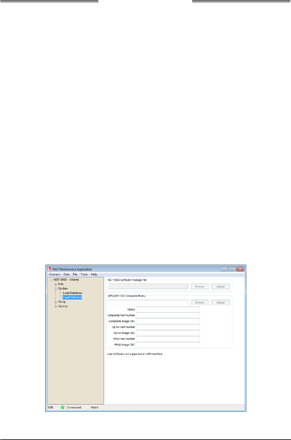
Lynx NGT-9000s
Installation Manual
4.5 USING THE MAINTENANCE PC
The Maintenance PC (MPC) and Lynx Maintenance Application Tool (Lynx MAT) are used to interface
with the Lynx NGT-9000s to load software/firmware/databases, view factory / version data, retrieve fault
/ event logs, data recording, and simulating live data.
These procedures assume the following:
• Power is being supplied to the aircraft and unit and system components.
• The correct Lynx MAT software is being used to load software. See the General Information section
(Software Versions) for software details. Note - Each version of software for the MSS device
requires a specific MAT software version that is compatible.
• The software to be loaded is available on the MPC being used.
• The Lynx MAT is active on the MPC.
• The MPC is interfaced to the unit.
• The MPC and unit are communicating and the unit is in Maintenance Mode.
Additional instructions on using the MPC are given in the Installation Checkout section.
4.5.1 Load Software
This procedure is used to update the system software used by the unit. The MPC must be connected via
the USB connection for this procedure. The WiFi interface is not supported.
1. From the Lynx MAT select UpdateZLoad Software. See Figure 4-3.The tool has the option of
loading either of the following software files. Note - Do not remove power to the unit or disconnect
the MPC during this procedure.
• Lynx NGT-9000s Software Package File (composed of Flight, Maintenance, and Bootloader)
• GPS/UAT Composite Binary file (composed of CCA Operation SW and Firmware)
• Press the Browse button to open a file window. Select the appropriate file. (i.e. 1090MSS.pkg /
GPS/UAT.bin or similar looking file). The MAT verifies the contents of the file to be loaded.
This takes approximately 5 seconds.
• Press the Upload button to begin loading the software to the unit. A progress bar is shown for
each SW load.
Figure 4-3: Lynx MAT – Update Software
0040-17001-01 Maintenance Page 4-15
Revision A January 15, 2015
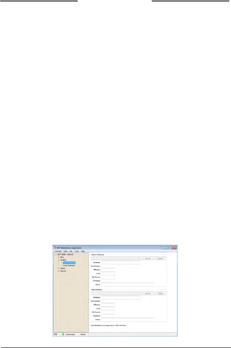
Lynx NGT-9000s
Installation Manual
2. An upload completed message is shown when the procedure has finished.
• A failure message is shown if a problem loading the Lynx NGT-9000s Software Package File is
detected. Check that the file being loaded is correct and try the procedure again. If the problem
continue cycle power to the unit.
• A problem is detected for the GPS/UAT Composite Binary File if the validation check of the file
has failed. Check that the file being loaded is correct and try the procedure again. If the problem
continues cycle power to the unit and try again.
3. After the unit restarts, re-connect the unit to the Lynx MAT.
4. From the Lynx MAT select ServiceZRestart Unit ModeZ Maintenance.
5. Verify that the software was updated by going to the Versions page. From the Lynx MAT select
InfoZVersions.
6. Cycle power to the unit. (Note –The Lynx MAT and PC may be disconnected at this time if no other
maintenance is required. If disconnected Skip step 8.
7. From the Lynx MAT select ServiceZRestart Unit ModeZ Operational Software.
8. Perform a functional check (paragraph 3.6.1) to verify unit is functioning correctly. Refer to the fault
isolation section if errors are detected.
4.5.2 Load Databases
This procedure is used to update the databases used by the Lynx NGT-9000s. Updates to the databases are
not mandatory and are updated at the discretion of the user. Refer to Software Updates in the General
Information section for details on obtaining new database files.
1. From the Lynx MAT select UpdateZ Load Database. See Figure 4-4. The tool has the option of
loading any of the following database files.
• Airport Database
• Map Database
2. Press the Browse button to open a file window. Select the appropriate file.
3. Press the Upload button to begin loading the database to the unit.
4. An upload completed message is shown when the procedure has finished.
• A failure message is shown if a problem loading the database is detected. Check that the file being
loaded is correct and try the procedure again. If the problem continue cycle power to the unit.
5. The procedure can be repeated for the other available databases.
6. When the procedures are complete cycle power to the unit and perform a functional check (paragraph
3.6.1) to verify unit is functioning correctly. Refer to the fault isolation section if errors are detected.
Figure 4-4: Lynx MAT – Update Database
Page 4-16 Maintenance 0040-17001-01
January 15, 2015 Revision A
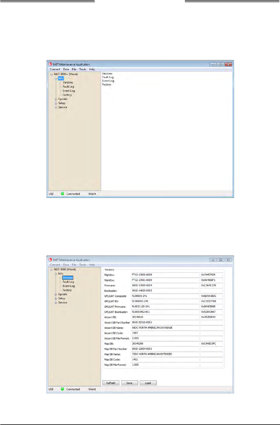
Lynx NGT-9000s
Installation Manual
4.5.3 View or Retrieve Data
Use the Lynx MAT to view versions and factory information and retrieve fault and event logs. See Figure
4-5. The versions data, event log, and factory log can be saved to a file for later viewing.
Figure 4-5: Lynx MAT – Information
4.5.3.1 Versions
The Versions page shows the current software and database versions on the unit. Buttons on the bottom of
the page provide the user the options of ‘Refresh’, ‘Save’, and ‘Load’.
Figure 4-6: Lynx MAT – Version
0040-17001-01 Maintenance Page 4-17
Revision A January 15, 2015

Lynx NGT-9000s
Installation Manual
4.5.3.2 Fault Log
The Fault Log can be used for troubleshooting. Each fault is entered on its own indexed row, with details
for date, time, etc. Clicking on a row provides the user with additional information at the top of the page.
This information includes a fault description and a possible description of the loss of functionality.
Buttons on the bottom of the page provide the user the options of ‘Refresh’, ‘Clear’, ‘Filter’, ‘Save’,
‘Load’, and ‘Export to CSV’. The fault data can be cleared at the option of the user.
NOTE
Typically the fault log should not be cleared unless instructed by L-3 AS
Field Service personnel.
A saved fault log can be viewed by the Lynx MAT when the unit is not connected by using the Load
function.
Table 4-3: List of Fault Log Messages
FAULT ID/ CODE
(HEX) FAULT DESCRIPTION CORRECTIVE ACTION
0x00000001 Kernel Fault Wd Expire Reboot the unit and check if the fault
persists. Contact L-3 Field Service before
removal.
0x00000002 Kernel Fault Process Term Reboot the unit and check if the fault
persists. Contact L-3 Field Service before
removal.
0x00000003 Kernel Fault Thread Term Reboot the unit and check if the fault
persists. Contact L-3 Field Service before
removal.
0x00000004 Kernel Fault Thread Timeout Reboot the unit and check if the fault
persists. Contact L-3 Field Service before
removal.
0x00000005 Kernel Fault Trap Reboot the unit and check if the fault
persists. Contact L-3 Field Service before
removal.
0x00000006 Kernel Fault BIT Wd Reboot the unit and check if the fault
persists. Contact L-3 Field Service before
removal.
0x00000007 Kernel Fault BIT Clock Reboot the unit and check if the fault
persists. Contact L-3 Field Service before
removal.
0x00000008 Kernel Fault CBIT CRC Reboot the unit and check if the fault
persists. Contact L-3 Field Service before
removal.
0x00000009 Kernel Fault ISR Limit Reboot the unit and check if the fault
persists. Contact L-3 Field Service before
removal.
0x0000000A Kernel Fault CBIT FPGA Reboot the unit and check if the fault
persists. Contact L-3 Field Service before
removal.
0x0000000B Kernel Fault CBIT SW Exception Reboot the unit and check if the fault
persists. Contact L-3 Field Service before
removal.
Page 4-18 Maintenance 0040-17001-01
January 15, 2015 Revision A

Lynx NGT-9000s
Installation Manual
Table 4-3: List of Fault Log Messages
FAULT ID/ CODE
(HEX) FAULT DESCRIPTION CORRECTIVE ACTION
0x00000021 Touch INIT Fault Reboot the unit and check if the fault
persists. Contact L-3 Field Service before
removal.
0x00000033 IODC INIT Fault Reboot the unit and check if the fault
persists. Contact L-3 Field Service before
removal.
0x00000034 IODC Read Fault Reboot the unit and check if the fault
persists. Contact L-3 Field Service before
removal.
0x00000035 IODC Overflow Fault Reboot the unit and check if the fault
persists. Contact L-3 Field Service before
removal.
0x00000036 IODC Buffer Overflow Fault Reboot the unit and check if the fault
persists. Contact L-3 Field Service before
removal.
0x00000037 IODC Parity Fault Reboot the unit and check if the fault
persists. Contact L-3 Field Service before
removal.
0x00000047 Fault ID for the watchdog test failure Reboot the unit and check if the fault
persists. Contact L-3 Field Service before
removal.
0x00000048 Fault ID for the memory test failure Reboot the unit and check if the fault
persists. Contact L-3 Field Service before
removal.
0x00000049 Fault ID for the DSP Clock test
failure Reboot the unit and check if the fault
persists. Contact L-3 Field Service before
removal.
0x0000004A Fault ID for the FPGA test failure Reboot the unit and check if the fault
persists. Contact L-3 Field Service before
removal.
0x0000004B Fault ID for the Power management
test failure Reboot the unit and check if the fault
persists. Contact L-3 Field Service before
removal.
0x0000004C Fault ID for the Primary Image failure
Reboot the unit and check if the fault
persists. Contact L-3 Field Service before
removal.
0x0000004D Fault ID for the Secondary Image
failure Reboot the unit and check if the fault
persists. Contact L-3 Field Service before
removal.
0x00001001 Oscillator Synthesizer Out of Lock
Possible Cause
ADS-B In Internal Degraded
ADS-B Out Internal Failure
TAS Internal Failure
Transponder Internal Failure
Reboot the unit and check if the fault
persists. Contact L-3 Field Service before
removal.
0040-17001-01 Maintenance Page 4-19
Revision A January 15, 2015

Lynx NGT-9000s
Installation Manual
Table 4-3: List of Fault Log Messages
FAULT ID/ CODE
(HEX) FAULT DESCRIPTION CORRECTIVE ACTION
0x00001002
Mutual Supp Bus Failed to Assert
No failures of the box only log the
fault
Reboot the unit and check if the fault
persists. Contact L-3 Field Service before
removal.
0x00001003
Mutual Supp Bus Stuck High
No failures of the box only log the
fault
Reboot the unit and check if the fault
persists. Contact L-3 Field Service before
removal.
0x00001004
DCM CRC Failure
No failures of the box only log the
fault
Reboot the unit and check if the fault
persists. Contact L-3 Field Service before
removal.
0x00001006 DCM Configuration Failure Reboot the unit and check if the fault
persists. May need to update or load
configuration data.
Contact L-3 Field Service before removal.
0x00001007
Over Temp on Ground
Possible Cause
ADS-B In Internal failure
ADS-B Out Internal failure
TAS Internal failure
Transponder Internal failure
GPS Internal failure
FIS-B Internal failure
Log the fault and allow the unit to cool
down. If the fault continues to be seen
contact L-3 Field Service before removal.
0x00001008 Over Temp in Air
No failures of the box only log the
fault
Log the fault and allow the unit to cool
down. If the fault continues to be seen
contact L-3 Field Service before removal.
0x00001009 Failure of Power Monitor Reboot the unit and check if the fault
persists. May need to update or load
configuration data.
Contact L-3 Field Service before removal.
0x0000100A Power Out of Tolerance
Possible Cause
ADS-B In Internal failure
ADS-B Out Internal failure
TAS Internal failure
Transponder Internal failure
GPS Internal failure
FIS-B Internal failure
Reboot the unit and check if the fault
persists. May need to update or load
configuration data.
Contact L-3 Field Service before removal.
0x0000100B Airport DB Flash CRC Failure
Possible Cause
Airport database failure
FIS-B internal degraded
Reboot the unit and check if the fault
persists. May need to update or load
navigation database data.
Contact L-3 Field Service before removal.
0x0000100C Airport DB Flash Compatibility
Failure
Airport database failure
FIS-B internal degraded
Reboot the unit and check if the fault
persists. May need to update or load
navigation database data.
Contact L-3 Field Service before removal.
Page 4-20 Maintenance 0040-17001-01
January 15, 2015 Revision A

Lynx NGT-9000s
Installation Manual
Table 4-3: List of Fault Log Messages
FAULT ID/ CODE
(HEX) FAULT DESCRIPTION CORRECTIVE ACTION
0x0000100D Map DB Flash CRC Failure
Map database failure
FIS-B internal degraded
Reboot the unit and check if the fault
persists. May need to update or load map
database data.
Contact L-3 Field Service before removal.
0x0000100E Map DB Flash Compatibility Failure
Map database failure
FIS-B internal degraded
Reboot the unit and check if the fault
persists. May need to update or load map
database data.
Contact L-3 Field Service before removal.
0x00001011 Operational SW RAM CRC Failure
Failure causes a reset
Log the fault.
0x00001012 Airport DB RAM CRC Failure
Failure causes a reset
Reboot the unit and check if the fault
persists. May need to update or load
airport database data.
Contact L-3 Field Service before removal.
0x00001013 Map DB RAM CRC Failure
Failure causes a reset
Log the fault.
0x00001015 Factory Data RAM CRC Failure
Failure causes a reset
Log the fault.
0x00001016 Config Data RAM CRC Failure
Failure causes a reset
Reboot the unit and check if the fault
persists. Contact L-3 Field Service before
removal.
0x00001017 Factory Data NVM CRC Failure
Failure causes a reset
Reboot the unit and check if the fault
persists. Contact L-3 Field Service before
removal.
0x00001018 Factory Data Compatibility Failure
Failure causes a reset
Reboot the unit and check if the fault
persists. Contact L-3 Field Service before
removal.
0x00001019 Config Data NVM CRC Failure
Failure causes a reset
Reboot the unit and check if the fault
persists. Contact L-3 Field Service before
removal.
0x0000101A Config Data NVM Compatibility
Failure
Failure causes a reset
Reboot the unit and check if the fault
persists. Contact L-3 Field Service before
removal.
0x0000101B Power Loss In Air Check Table 4-1 or Table 4-2
0x0000101C Ambient Light Sensor Failure Reboot the unit and check if the fault
persists. Contact L-3 Field Service before
removal.
0x00001801 Clear Oscillator Synthesizer Out of
Lock Reboot the unit and check if the fault
persists. Contact L-3 Field Service before
removal.
0x00001802 Clear Mutual Supp Bus Failed to
Assert Reboot the unit and check if the fault
persists. Contact L-3 Field Service before
removal.
0x00001803 Clear Mutual Supp Bus Stuck High Reboot the unit and check if the fault
persists. Contact L-3 Field Service before
removal.
0040-17001-01 Maintenance Page 4-21
Revision A January 15, 2015

Lynx NGT-9000s
Installation Manual
Table 4-3: List of Fault Log Messages
FAULT ID/ CODE
(HEX) FAULT DESCRIPTION CORRECTIVE ACTION
0x00001804 Clear DCM CRC Failure Log the fault.
0x00001806 Clear DCM Configuration Fail Log the fault.
0x00001807 Clear Over Temp on Ground Log the fault.
0x00001808 Clear Over Temp in Air Log the fault.
0x00001809 Clear Failure of Power Monitor Log the fault.
0x0000180A Clear Power Out of Tolerance Log the fault.
0x0000180B Clear Airport DB Flash CRC Failure Log the fault.
0x0000180C Clear Airport DB Flash Compatibility
Failure Log the fault.
0x0000180D Clear Map DB Flash CRC Failure Log the fault.
0x0000180E Clear Map DB Flash Compatibility
Failure Log the fault.
0x00001811 Clear Operational SW RAM CRC
Failure Log the fault.
0x00001812 Clear Airport DB RAM CRC Failure Log the fault.
0x00001813 Clear Map DB RAM CRC Failure Log the fault.
0x00001815 Clear Factory Data RAM CRC
Failure Log the fault.
0x00001816 Clear Config Data RAM CRC Failure Log the fault.
0x00001817 Clear Factory Data NVM CRC
Failure Log the fault.
0x00001818 Clear Factory Data Compatibility
Failure Log the fault.
0x00001819 Clear Config Data NVM CRC Failure Log the fault.
0x0000181A Clear Config Data NVM Compatibility
Failure Log the fault.
0x0000181B Clear Power Loss In Air Log the fault.
0x0000181C Clear Ambient Light Sensor Failure Log the fault.
0x00002001 Audio Mute While On Ground
Audio external failure
Log the fault.
0x00002002 TAS Antenna Failure
TAS External failure
Check Table 4-1 or Table 4-2
0x00002003 1090 ADSB Rcvr Btm Power Failure
ADS-B In Internal degraded
TAS Internal failure
Reboot the unit and check if the fault
persists. Contact L-3 Field Service before
removal.
0x00002004 1090 ADSB Rcvr Top Power Failure
ADS-B In Internal degraded
TAS Internal failure
Reboot the unit and check if the fault
persists. Contact L-3 Field Service before
removal.
0x00002005 TAS 1090 (ATCRBS) Receiver Data
Failure
TAS Internal failure
Reboot the unit and check if the fault
persists. Contact L-3 Field Service before
removal.
Page 4-22 Maintenance 0040-17001-01
January 15, 2015 Revision A

Lynx NGT-9000s
Installation Manual
Table 4-3: List of Fault Log Messages
FAULT ID/ CODE
(HEX) FAULT DESCRIPTION CORRECTIVE ACTION
0x00002008 FPGA TAS 1030 transmission failure
TAS Internal failure
Reboot the unit and check if the fault
persists. Contact L-3 Field Service before
removal.
0x00002009 TAS 1030 Transmission Power
Failure
TAS Internal failure
Reboot the unit and check if the fault
persists. Contact L-3 Field Service before
removal.
0x00002801 Clear audio Mute While On Ground Log the fault.
0x00002802 Clear AS Antenna Failure Log the fault.
0x00002803 Clear 1090 ADSB Rcvr Btm Power
Failure Log the fault.
0x00002804 Clear 1090 ADSB Rcvr Top Power
Failure Log the fault.
0x00002805 Clear TAS 1090 (ATCRBS) Receiver
Failure Log the fault.
0x00002808 Clear FPGA TAS 1030 transmission
failure Log the fault.
0x00002809 Clear TAS 1030 Transmission Power
Failure Log the fault.
0x00003001 Invalid Mode S Address
Transponder External failure
ADS-B Out Internal failure
Change DCM setting (ICAO address
should be other than 00000 or FFFFFF in
hex). See installation checkout for details.
0x00003002 FPGA 1090 Transmission Failure
Transponder Internal failure
ADS-B Out Internal failure
Reboot the unit and check if the fault
persists. Contact L-3 Field Service before
removal.
0x00003003 Squitter rate failure
ADS-B Out Internal failure
Reboot the unit and check if the fault
persists. Contact L-3 Field Service before
removal.
0x00003004 Squitter scheduler process not
running at expected rate
ADS-B Out Internal failure
Reboot the unit and check if the fault
persists. Contact L-3 Field Service before
removal.
0x00003005 1090 ATCRBS Rx Failure(loopback
without TAS antenna)
Transponder Internal failure
ADS-B Out Internal failure
Reboot the unit and check if the fault
persists. Contact L-3 Field Service before
removal.
0x00003006 1030 Rcvr Btm Power Failure
Transponder Internal failure
TAS Internal failure
Reboot the unit and check if the fault
persists. Contact L-3 Field Service before
removal.
0x00003007 1030 Rcvr Top Power Failure
Transponder Internal failure
TAS Internal failure
Reboot the unit and check if the fault
persists. Contact L-3 Field Service before
removal.
0x00003008 1030 Rcvr Btm PIN Isolation Failure
Transponder Internal failure
TAS Internal failure
Reboot the unit and check if the fault
persists. Contact L-3 Field Service before
removal.
0040-17001-01 Maintenance Page 4-23
Revision A January 15, 2015

Lynx NGT-9000s
Installation Manual
Table 4-3: List of Fault Log Messages
FAULT ID/ CODE
(HEX) FAULT DESCRIPTION CORRECTIVE ACTION
0x00003009 1030 Rcvr Top PIN Isolation Failure
Transponder Internal failure
TAS Internal failure
Reboot the unit and check if the fault
persists. Contact L-3 Field Service before
removal.
0x0000300A 1030 Rcvr Btm TR Isolation Failure
Transponder Internal failure
TAS Internal failure
Reboot the unit and check if the fault
persists. Contact L-3 Field Service before
removal.
0x0000300B 1030 Rcvr Top TR Isolation Failure
Transponder Internal failure
TAS Internal failure
Reboot the unit and check if the fault
persists. Contact L-3 Field Service before
removal.
0x0000300C 1030 XPDR ATCRBS Receiver
Failure
Transponder Internal failure
TAS Internal failure
Reboot the unit and check if the fault
persists. Contact L-3 Field Service before
removal.
0x0000300D XPDR 1090 XMIT Bottom Power
Failure
Transponder Internal failure
ADS-B Internal failure
Reboot the unit and check if the fault
persists. Contact L-3 Field Service before
removal.
0x0000300E XPDR 1090 XMIT Top Power Failure
Transponder Internal failure
ADS-B Internal failure
Reboot the unit and check if the fault
persists. Contact L-3 Field Service before
removal.
0x00003801 Clear Invalid Mode S Address Log the fault.
0x00003802 Clear FPGA 1090 Transmission
Failure Log the fault.
0x00003803 Clear Squitter rate failure Log the fault.
0x00003804 Clear Squitter scheduler process not
running at expected rate Log the fault.
0x00003805 Clear 1090 ATCRBS rx
Failure(without TAS antenna) Log the fault.
0x00003806 Clear 1030 Rcvr Btm Power Failure Log the fault.
0x00003807 Clear 1030 Rcvr Top Power Failure Log the fault.
0x00003808 Clear 1030 Rcvr Btm PIN Isolation
Failure Log the fault.
0x00003809 Clear 1030 Rcvr Top PIN Isolation
Failure Log the fault.
0x0000380A Clear 1030 Rcvr Btm TR Isolation
Failure Log the fault.
0x0000380B Clear 1030 Rcvr Top TR Isolation
Failure Log the fault.
0x0000380C Clear 1030 XPDR ATCRBS
Receiver Failure Log the fault.
0x0000380D Clear XPDR 1090 XMIT Bottom
Power Failure Log the fault.
Page 4-24 Maintenance 0040-17001-01
January 15, 2015 Revision A

Lynx NGT-9000s
Installation Manual
Table 4-3: List of Fault Log Messages
FAULT ID/ CODE
(HEX) FAULT DESCRIPTION CORRECTIVE ACTION
0x0000380E Clear XPDR 1090 XMIT Top Power
Failure Log the fault.
0x00004001 GPS Sensor Fail
ADS-B In Internal failure
ADS-B Out Internal Degraded
GPS Internal failure
Check Table 4-1 or Table 4-2
0x00004002 GPS Antenna Open/Short
ADS-B In External failure
ADS-B Out External Degraded
GPS External failure
Check if GPS antenna is properly
connected.
0x00004003 GPS/UAT LVDS Bus
ADS-B In Internal failure
ADS-B Out Internal Degraded
GPS Internal failure
FIS-B Internal failure
Check Table 4-1 or Table 4-2
0x00004801 Clear GPS Sensor Fail Log the fault.
0x00004802 Clear GPS Antenna Open/Short Log the fault.
0x00004803 Clear GPS/UAT LVDS Bus Log the fault.
0x00005001 UAT Sensor Failure
ADS-B In In ternal degraded
FIS-B Internal failure
Reboot the unit and check if the fault
persists. Contact L-3 Field Service before
removal.
0x00005801 Clear UAT Sensor Failure Log the fault.
0x00006003 Gillham C Bit Error
ADS-B In External failure
TAS External failure
Transponder External failure
Check wiring
Reboot the unit and check if the fault
persists. Contact L-3 Field Service before
removal.
0x00006004 RS232 Altitude Input Fail
ADS-B In External failure
TAS External failure
Transponder External failure
Check wiring
Reboot the unit and check if the fault
persists. Contact L-3 Field Service before
removal.
0x00006005 ARINC 429 Altitude Input Fail
ADS-B In External failure
TAS External failure
Transponder External failure
Check wiring
Reboot the unit and check if the fault
persists. Contact L-3 Field Service before
removal.
0x00006006 ARINC 429 AHRS Input Fail
ADS-B In External degraded
TAS External degraded
Check wiring
Reboot the unit and check if the fault
persists. Contact L-3 Field Service before
removal.
0x00006007 ARINC 429 Receiver #1 Loop Back
Failure causes a reset
Log the fault.
0x00006008 ARINC 429 Receiver #2 Loop Back
Failure causes a reset
Log the fault.
0040-17001-01 Maintenance Page 4-25
Revision A January 15, 2015

Lynx NGT-9000s
Installation Manual
Table 4-3: List of Fault Log Messages
FAULT ID/ CODE
(HEX) FAULT DESCRIPTION CORRECTIVE ACTION
0x00006009 Control Panel Input Fail
Transponder External failure
Check Control Panel wiring. (future)
Reboot the unit and check if the fault
persists. Contact L-3 Field Service before
removal.
0x00006803 Clear Gillham C Bit Error Log the fault.
0x00006804 Clear RS232 Altitude Input Fail Log the fault.
0x00006805 Clear ARINC 429 Altitude Input Fail Log the fault.
0x00006806 Clear ARINC 429 AHRS Input Fail Log the fault.
0x00006807 Clear ARINC 429 Receiver #1 Loop
Back Log the fault.
0x00006808 Clear ARINC 429 Receiver #2 Loop
Back Log the fault.
0x00006809 Clear Control Panel Input Fail Log the fault.
Page 4-26 Maintenance 0040-17001-01
January 15, 2015 Revision A
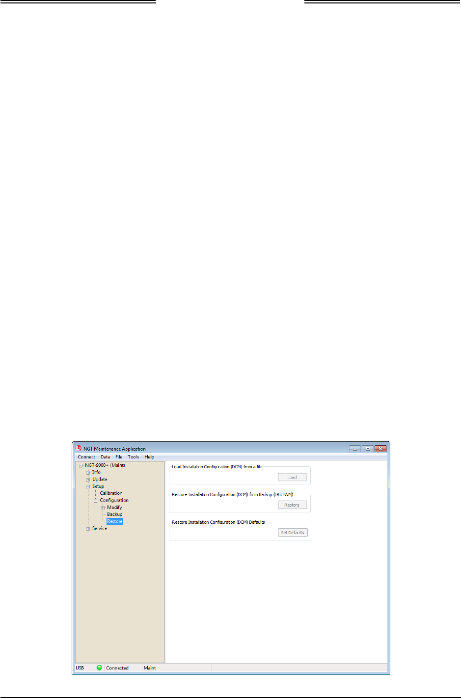
Lynx NGT-9000s
Installation Manual
4.5.4 Configuration Restore
This procedure is used to automatically fill in the configuration options from a backup file. See Figure 4-7.
Perform the following procedure using a MPC and Lynx MAT. This procedure assumes that the unit is in
Maintenance Mode and the MPC is interfaced to the unit using either the USB.
These procedures assume the following:
• Power is being supplied to the aircraft and Lynx NGT-9000s.
• The Lynx MAT is active on the MPC.
• The MPC is connected to the unit.
• A DCM is connected (via the mating connector)
• The MPC and unit are communicating. If not then from the Lynx MAT panel select
ConnectZNGT9000ZUSB. This is required each time the unit power is cycled.
1. From the Lynx MAT select Setup Z Configuration Z Restore. See Figure 4-7.
2. Click on the Load button to ‘Load a Pre-Existing Configuration File’ to load the configuration data
into the Lynx MAT. After the file is loaded into the Lynx MAT click on any of the Apply buttons to
save all the configuration options (see Note below). Note - A dialog window is shown asking if
changes should be saved immediately. See instructions given in the Installation Checkout section.
NOTE
The Tail Number and Mode S Identifier are unique for every aircraft. From
the Lynx MAT select Setup Z Configuration Z Modify Z Aircraft
Specific and enter the new data before pressing the Apply button.
3. Click on the Restore button to Restore Installation Configuration from Backup (NVM) to save the
backup configuration module data stored in the unit’s memory to the configuration module.
4. Click on the Set Defaults button to load default information to the configuration module.
5. From the Lynx MAT select ServiceZRestart Unit ModeZ Maintenance.
6. Validate the restoration of the configuration options by comparing the configuration data in the setup
pages with the log sheet for configuration and checkout created during initial installation.
Figure 4-7: Lynx MAT –Configuration - Restore
0040-17001-01 Maintenance Page 4-27
Revision A January 15, 2015
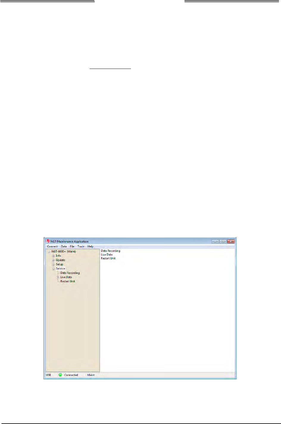
Lynx NGT-9000s
Installation Manual
4.5.5 Service
This procedure is used to service and troubleshoot the Lynx NGT-9000s. See Figure 4-8.
4.5.5.1 Data Recording
The information generated by the Data Recording page is not typically used unless requested by the
factory during service.
1. From the Lynx MAT select ServiceZData Recording.
2. Select the MMC Mode.
• Selecting Truncate restarts the recording.
• Selecting Append adds any new recording to the end of the current data recording.
3. Click on the “Enable” button.
4. From the Lynx MAT select ServiceZRestart Unit ModeZ Operational Mode.
5. Data recording begins. Recording continues until the unit is restarted again.
6. From the Lynx MAT select ServiceZRestart Unit ModeZ Maintenance mode.
7. From the Lynx MAT select ServiceZData Recording.
8. Selecting “Disable” to stop recording.
9. When needed use the ‘Clear’ button’ to erase the current recorded data.
10. The data can be stored to a file using the ‘Browse’ and “Download’ buttons.
4.5.5.2 Live Data
The Live Data function is used for troubleshooting. Instructions on how to use live data are located in the
Installation Checkout section under configuration check.
Figure 4-8: Lynx MAT – Service
Page 4-28 Maintenance 0040-17001-01
January 15, 2015 Revision A

Lynx NGT-9000s
Installation Manual
4.6 RETURN TO SERVICE
Use this section to validate the return to service of the Lynx NGT-9000s and system components.
4.6.1 Lynx NGT-9000s
Use this procedure to remove and replace all models of the panel mount NGT-9000s. The instructions
herein are generic in scope. The best established methods, techniques and practices should be used where
no specific procedure is given.
1. Removal Procedure
a. Locate the Panel Retainer access on the bottom left of the bezel.
b. Rotate the Panel Retainer CCW using 3/32 Allen Hex Socket Screw Driver. Rotate Panel
Retainer, approximately 40 turns, until it stops. Do not exceed 5.0 inch-pounds of torque.
c. Pull the unit from panel separating the main connector and antenna connections.
2. Installation Procedure
a. Use 3/32 Allen Hex Socket Screw Driver to rotate the Panel Retainer CCW to avoid
interference with the bottom edge of the panel.
b. Insert the unit in panel allowing the alignment guides to settle the unit into place.
c. Press the sides of the unit until the back side of the bezel is against the panel.
d. Rotate the Panel Retainer CW (approximately 40 turns) to lock the unit in place. The Panel
Retainer torque limit is 5.0 inch-pounds.
4.6.1.1 Functional Check Procedure
1. Cycle power to the unit and system components.
2. The Lynx NGT-9000s contain a GPS receiver that requires a full functional check (paragraph 3.10,
Installation Checkout) be performed to verify unit is functioning correctly.
3. Models of NGT-9000 with the TAS function must perform the TAS Antenna Calibration (installation
checkout paragraph 3.10.2.8) prior to doing a functional check.
4. Refer to the fault isolation section if errors are detected.
0040-17001-01 Maintenance Page 4-29
Revision A January 15, 2015

Lynx NGT-9000s
Installation Manual
4.6.2 Detachable Configuration Module
Use this procedure to remove and replace the DCM. The instructions herein are generic in scope. The best
established methods, techniques and practices should be used where no specific procedure is given.
NOTE
Before removal (and if possible) the configuration data should be saved.
Refer to the Lynx MAT Backup instructions located in the installation
checkout section.
1. Removal Procedure
a. Locate the Panel Retainer access on the bottom left of the Lynx NGT-9000s bezel.
b. Rotate the Panel Retainer CCW using 3/32 Allen Hex Socket Screw Driver.
c. Pull the unit from panel separating the main connector and antenna connections.
d. Remove 6 screws securing panel rack and remove panel.
e. Remove 4 screws securing rear plate to panel rack.
f. Remove 2 screws securing P1 mating connector and nut plate. Remove screw securing ground
strap to rear plate.
g. From the wire bundle remove tie wraps securing overbraid.
h. Slide overbraid to expose configuration module.
i. Remove configuration module contacts from the P1 mating connector.
2. Installation Procedure
a. Insert contacts of new configuration module into P1 mating connector. Refer to Installation
Guidelines for the Configuration Module in the installation section for details on the
configuration module and configuration module electrical interface.
b. Slide overbraid back into position, and use a new tie wraps to secure overbraid.
c. Secure P1 mating connector to rear plate using nut plate and 2 screws.
d. Secure cable ground strap to rear plate using 1 screw.
e. Secure rear plate to panel rack using 4 screws.
f. Insert panel in installation location and secure panel using 6 screws.
g. Secure panel rack using 6 screws.
h. On the Lynx NGT-9000s use 3/32 Allen Hex Socket Screw Driver to rotate the panel retainer
counterclockwise to avoid interference with the bottom edge of the panel.
i. Insert the Lynx NGT-9000s in panel allowing the alignment guides to settle the unit into place.
j. Press the sides of the unit until the back side of the bezel is against the panel.
k. Rotate the panel retainer clockwise to lock the Lynx NGT-9000s in place. The Panel Retainer
torque limit is 5.0 inch-pounds.
3. Functional Check Procedure
a. Cycle power to the Lynx NGT-9000s and system components.
b. Ensure no failure messages are annunciated on the controller/display/PED and fail lamp is
extinguished after GPS has acquired a signal.
c. Use the installation checkout section to perform the select configuration options procedure or
use the maintenance sections configuration restore is the original configuration (.bin) file can be
retrieved from the original installer of the configuration module.
d. Perform the checkout procedure provided in the installation checkout to verify unit is
functioning correctly.
• Refer to the fault isolation section if errors are detected.
Page 4-30 Maintenance 0040-17001-01
January 15, 2015 Revision A

Lynx NGT-9000s
Installation Manual
4.6.3 Directional Antenna (NY156 and NY164)
The TAS Antenna Calibration (installation checkout paragraph 3.10.2.8) must be performed anytime the
Lynx NGT-9000s or Directional Antenna is removed from the aircraft. Specific details on the installation
of the antenna can be found in the installation section.
1. Removal Procedure
a. Remove 10-32 hardware (nut and bolts) Qty 4, O-ring, and adapter plate.
b. Disconnect three antenna cables.
2. Installation Procedure
a. Connect each of the three antenna cables. Check to ensure that each cable is connected to the
correct antenna connector. Each connector/cable has a matching color band.
b. Attach the antenna to the aircraft, with the special adapter plate and o-ring, using 10-32
hardware. Ensure correct direction of antenna. Refer to Figure 2-15 for details.
• Before installing the antenna on an aircraft remove the tape, which holds the O-RING
gasket in place during shipment (refer to SL-206). If the O-ring is in a separate bag,
remove and install it in the O-ring groove on the bottom of the antenna.
• For pressurized aircraft, use a sealant that meets the requirements of SAE AMS-S-8802 such
as Flamemaster CS3204 class B. For non-pressurized aircraft, use a non-corrosive sealant that
meets the physical requirements of MIL-A-46146 such as General Electric RTV162.
3. Functional Check Procedure
a. Cycle power to the Lynx NGT-9000s and system components.
b. Perform the TAS Antenna Calibration (installation checkout paragraph 3.10.2.8) prior to doing
a functional check.
c. Perform a functional check (paragraph paragraph 3.10, Installation Checkout) to verify unit is
functioning correctly.
• Refer to the fault isolation section if errors are detected.
4.6.4 L-Band (UAT/1090) Antenna
1. Refer to the aircraft manufacturer's data and the antenna manufacturer's installation instructions to
remove and replace the antenna(s).
a. Perform a functional check (paragraph paragraph 3.10, Installation Checkout) to verify unit is
functioning correctly.
• Refer to the fault isolation section if errors are detected.
4.6.5 GPS Antenna
1. Refer to the aircraft manufacturer's data and the antenna manufacturer's installation instructions to
remove and replace the antenna(s).
a. Perform a functional check (paragraph paragraph 3.10, Installation Checkout) to verify unit is
functioning correctly.
• Refer to the fault isolation section if errors are detected.
0040-17001-01 Maintenance Page 4-31
Revision A January 15, 2015

Lynx NGT-9000s
Installation Manual
4.7 DISPOSITION OF FAILED ITEMS
1. The Lynx NGT-9000s can only be repaired by a FAA Certified Repair Station Facility.
2. The configuration module, NY156, and NY164 cannot be repaired and must be replaced.
3. Return defective components to:
L-3 Avionics Systems
Attn: Field Service
5353 52nd Street, S.E.
Grand Rapids, MI USA 49512-9704
4. Refer to the manufactures data for external displays, controllers, and antennas interfaced to the Lynx
NGT-9000s.
5. If available, pack components in their original shipping container. If the original container is not
available, pack them as follows:
CAUTION
Do not use desiccant crystals when packaging electronic assemblies.
Since the assembly must be packed tightly, crystals in bag form cannot
be used. The use of loose crystals may cause unnecessary damage
resulting in a cleaning problem.
a. Ensure that conductive covers/caps are installed on the exposed terminals of connector, if
applicable.
b. LRU's that are marked as electrostatic discharge sensitive (ESDS) must be wrapped in static
protective materials.
c. Wrap with bubble pack. Secure bubble pack with reinforced tape.
d. Place assembly in a cardboard box.
e. Wrap any accessories in tissue and place in the box. Fill spaces with bubble pack.
f. Place an explanation letter in the box with the following information.
• Your name, address, and telephone number.
• Purchase order number.
• Description of component including, when applicable, model and serial number.
• A brief description of the difficulty.
g. Shut box, and seal with reinforced tape.
h. Attach packing list to outside of box.
Page 4-32 Maintenance 0040-17001-01
January 15, 2015 Revision A

Lynx NGT-9000s
Installation Manual
Appendix
A
Interface Signal Name & Cable Characteristics
A.1 INTRODUCTION
This appendix defines digital interface label information and electrical characteristics of all input and
output signal names to the Lynx NGT-9000s Multilink Surveillance System (the unit). Sufficient data is
included to use a bus reader for the purpose of identifying signal input and output characteristics and
perform an electrical load analysis for the aircraft. The input and output interfaces are sometimes
configurable as noted in the following paragraphs.
The interface characteristics contained in this appendix are fully compatible with ARINC specifications
where noted. Connection information identifies the connector-pin and signal names as shown on the
external interconnect wiring diagram in the installation section.
A.2 INPUT AND OUTPUT INTERFACES
A.2.1 Input Power
The unit has two power inputs available for either +14 VDC or +28VDC operation. The inputs are not
diode isolated and are intended to be tied to the same power input device in order to handle the required
current.
A.2.2 RF Suppression Bus
The transmission asserts a positive voltage on the output to provide the suppression to other L-band
equipment on the airplane. The suppression pulse output is DC coupled, and drives positive pulses not
less than 18 Vdc or greater than 70 Vdc into system loads from 300 to 2000 Ohms with a shunt
capacitance of up to 1850 pF. The signal meets the hardware characteristics as defined in ARINC 735B
Attachment 8.
A.2.3 Audio Output
The audio output shall be capable of supplying up to 40 milli Watts (RMS) at 1000 Hz into a 600 Ohm
audio distribution system. This output is directly compatible with industry standard audio panels.
A.2.4 Gilham Input (Altitude Input)
The Gillham interface is optional. Only one altimeter input source (gray code, ARINC-429 or RS-232)
may be connected. The Gillham interface consists of 11 discrete lines. These 11 discrete lines represent
11 binary digits representing the Gillham encoded pressure altitude. The Gillham code uses a modified
Gray code algorithm to ensure that no more than one bit changes between adjacent altitudes. The three
lowest significant bits represent 100 foot increments. The eight highest significant bits represent 500 foot
increments.
The digits are labeled as follows beginning with the most significant bit to the least significant bit (D2,
D4, A1, A2, A4, B1, B2, B4, C1, C2, C4).
0040-17001-01 Appendix A Page A-1
Revision A January 15, 2015
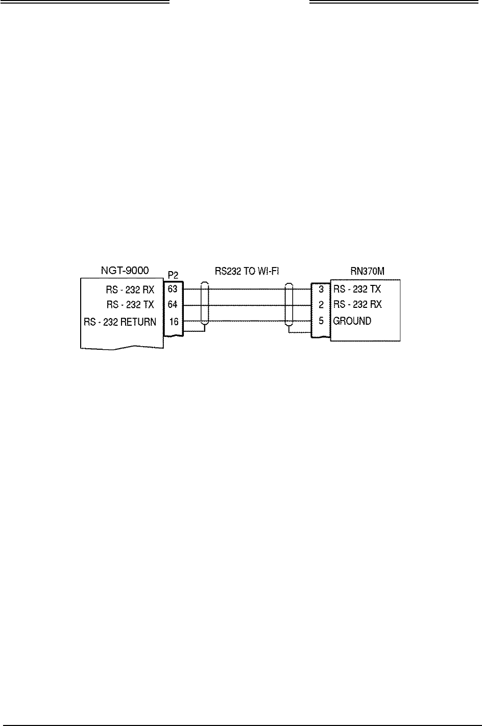
Lynx NGT-9000s
Installation Manual
A.2.5 RS-232 Interface
The RS-232 is a serial interface used to receive and transmit altitude data, interface with Control Panel,
and interface with Wi-Fi Device. The altitude data and Wi-Fi are optional depending on the installation.
A.2.5.1 RS-232 WiFi Output
The RS-232 WiFi interface is optional. An optional equipment interface wiring diagram is shown in
Figure A-1. When configured the NGT-9000 outputs the following information to a WiFi connection:
• FIS-B Weather Data
• ADS-B Traffic Data
• Ownship Data
A.2.5.1.1 Compatible PED Interconnect Layout
Figure A-1 provides interconnect information for the RN370M PED Accessory.
Figure A-1: RN370M Interconnect Option for RS-232 to WiFi Converter
Page A-2 Appendix A 0040-17001-01
January 15, 2015 Revision A

Lynx NGT-9000s
Installation Manual
A.2.5.2 RS-232 Altitude Data
The RS-232Altitude Data interface is optional. Only one altimeter input source (gray code, ARINC-429
or RS-232) should be connected.
1. When the Trimble/Garmin/Icarus protocol option is used, the following characteristics are set:
• Requires Altitude Encoder and Control Panel interface
• Baud rate is set to 9600 bps
• Data bits 8
• Parity none
2. When the Northstar protocol option is used, the following characteristics are set:
• Requires Altitude Encoder and Control Panel interface
• Baud rate is set to 2400 bps
• Data bits 8
• Parity none
3. When the UPS AT protocol option is used, the following characteristics are set:
• Requires Altitude Encoder and Control Panel interface
• Baud rate is set to 1200 bps
• Data bits 8
• Parity none
4. When the UPS AT Loran 618 protocol option is used, the following characteristics are set:
• Requires Altitude Encoder and Control Panel interface
• Baud rate is set to 1200 bps
• Data bits 7
• Parity odd
5. When the MAGELLAN protocol option is used, the following characteristics are set:
• Requires Altitude Encoder and Control Panel interface
• Baud rate is set to 1200 bps
• Data bits 8
• Parity even
6. When the SHADIN protocol option is used, the following characteristics are set:
• Requires Altitude Encoder and Control Panel interface
• Baud rate is set to 9600 bps
• Data bits 8
• Parity odd
7. When the ARNAV protocol option is used, the following characteristics are set:
• Requires Altitude Encoder interface
• Baud rate is set to 9600 bps
• Data bits 8
• Parity odd
A.2.6 RS-422 Interface
The RS-422 is a serial interface used to output weather data to a compatible display.
0040-17001-01 Appendix A Page A-3
Revision A January 15, 2015

Lynx NGT-9000s
Installation Manual
A.2.7 ARINC 429 Input
Four ARINC 429 Input receivers are available. The ARINC 429 input can be configured to receive data at
low (12.0 to 14.5 kbps) or high (100 kbps). The ARINC Bus is dedicated to the functions listed below:
• ARINC 429 Bus 1 used to input Pressure Altitude data.
• ARINC 429 Bus 2 used to input AHRS data.
• ARINC 429 Bus 3 is spare.
• ARINC 429 Bus 4 is configurable.
A.2.7.1 ARINC 429 Input Labels
1. The following ARINC 429 labels are inputs from Pressure Altitude on Bus #1:
• Label 203 – Pressure Altitude Uncorrected (BNR)
• Label 204 – Baro Corrected Altitude (BNR)
• Label 205 – Mach (BNR)
• Label 206 – Computed Airspeed (BNR)
• Label 210 – True Airspeed (BNR)
• Label 212 – Altitude Rate (BNR)
• Label 234 – Baro Correction, mB (BNR)
2. The following ARINC 429 labels are inputs from an Attitude and Heading Reference System (AHRS)
on Bus #2:
• Label 314 – True Heading
• Label 320 – Magnetic Heading
• Label 325 – Roll Angle (BNR)
• Label 335 – Track Angle Rate
3. The following ARINC 429 labels are inputs on bus #4 when configured for Combo Bus:
• Label 101 – Selected Heading
• Label 102 – FMS Selected Altitude (SDI set to FMS)
• Label 102 – MCP Selected Altitude (SDI set to MCP)
Page A-4 Appendix A 0040-17001-01
January 15, 2015 Revision A

Lynx NGT-9000s
Installation Manual
A.2.8 ARINC 429 Output
The unit has one ARINC 429 Output that transmits data at high (100 kbps). The Lynx NGT-9000s have
the option of interfacing to the Traffic display over the ARINC 429 bus using the standard traffic display
(STIF) format as defined in ARINC 735 and the Display Traffic Information File (DTIF) as described in
ARINC 735B. The specific display format is configurable through the DCM.
NOTE
The Lynx NGT-9000s follows the same STIF display as the L-3 SKY-
497 TAS system. Select that option (if available) in the STIF display
configuration settings.
A.2.8.1 ARINC 429 Output Labels
The following ARINC 429 labels are output to a Traffic Display on Bus #1:
• Label 013 - TCAS Display Control (DSC)
• Label 015 - Altitude Select Limits (DSC)
• Label 016 - Mode S Control Panel Data (DSC)
• Label 163 - Application Availability (DSC)
• Label 270 - Vertical Resolution Advisories (DSC)
• Label 274 - Selected Sensitivity Level (DSC)
• Label 350 - TCAS Fault Summary (DSC)
• Label 371 - GA Equipment ID (DSC)
• Label 377 - Equipment ID (DSC)
• Label 110 - Own Aircraft Latitude - Coarse (BNR)
• Label 111 - Own Aircraft Longitude - Coarse (BNR)
• Label 120 - Own Aircraft Latitude - Fine (BNR)
• Label 121 - Own Aircraft Longitude - Fine (BNR)
• Label 203 – Own Aircraft Barometric Altitude (Uncorrected) (BNR)
• Label 310 - Own Aircraft Latitude - Coarse (BNR)
• Label 311 - Own Aircraft Longitude - Coarse (BNR)
• Label 312 - Own Aircraft Ground Speed (BNR)
• Label 313 - Own Aircraft True Track Angle (BNR)
• Label 314 - Own Aircraft True Heading (BNR)
• Label 320 - Own Aircraft Magnetic Heading (BNR)
• Standard TCAS Intruder File (when enabled)
• Display Traffic Information File (when enabled)
0040-17001-01 Appendix A Page A-5
Revision A January 15, 2015

Lynx NGT-9000s
Installation Manual
A.2.9 Discrete Input
The unit has 6 discrete inputs that are set to GND/Open. The GND position is typically (depending on
configuration options) the active (ON) position.
The discrete inputs provide 1.0 ± 0.25 ma of current when the input is grounded. The input is in the
ground state when input voltage is less than or equal to 3.5Vdc, or there is less than 10 Ohms impedance
to ground. The input is in the open state when the input voltage is greater than or equal to 18.0Vdc, or
there is greater than 100K Ohms impedance to ground. The discretes are dedicated or reserved as stated
below:
• Discrete #1 is used for IDENT command which is used to signal the unit to identify itself with
IDENT signal. The discrete is set to GND/Open. The GND position indicates IDENT being
transmitted.
• Discrete #2 is used for external Audio Mute which is used input to signal the unit to suppress all
audio output. The discrete is set to GND/Open. The active position mutes the audio.
• Discrete #3 is used for On Ground status which used to determine whether ownship is in air or on
ground. The discrete is called Weight On Wheels (WOW) which can be connected to either a squat
switch, airspeed monitor, or a collective switch. The discrete can be set in the DCM settings to either
ground on ground, open on ground, or not used.
• Discrete #4 is reserved
• Discrete #5 is reserved
• Discrete #6 is reserved
A.2.10 Discrete Output
The unit has 6 discrete outputs that are set to GND/Open.
The ground logic state has an output voltage of < 3.0Vdc when sinking 250mA of current. The open logic
state has an output impedance of > 100K ohms to ground for voltages applied to the output of 0.0 to
36.0Vdc.
The outputs have the capability of driving a Type 313 lamp. The lamp must have an initial resistance at
turn ON (cold) of 28Ω minimum and a steady state ON resistance of 280Ω minimum.
The discretes are dedicated or reserved as stated below:
• Discrete #1 is reserved
• Discrete #2 is reserved.
• Discrete #3 is used for TAS Alert. The discrete is set to GND/Open. The active position indicates
Traffic Alert.
• Discrete #4 is used for TIS-B Not In Coverage. The discrete is set to GND/Open.
• Discrete #5 is reserved.
• Discrete #6 is used for ADS-B Out Fail. The discrete is set to GND/Open.
Page A-6 Appendix A 0040-17001-01
January 15, 2015 Revision A

Lynx NGT-9000s
Installation Manual
A.2.11 I2C Serial Bus (Detachable Configuration Module)
The I2C serial bus is used to communicate with the Detachable Configuration Module to store the
following configuration options:
1. Configuration module Config Version
2. Configuration module Configuration Data CRC
3. Installation Calibration Parameters (non-box specific)
• Audio Volume Level
•
TAS Antenna Calibration and Serial Number
4. Aircraft Specific Configuration Options
• Aircraft Tail Number
• Mode S Identifier
• Transponder Diversity Enable
• TAS Enable
• TAS Extended Callout Enable
• TAS Directional Antenna Type
• Antenna Installation
• TAS Directional Antenna Type
• Aircraft Emitter Category Type Code
• Broadcast Category
• Pilot Entry of Flight ID
• Aircraft Length and Width Code
• Aircraft Maximum Airspeed
• Normal Traffic Color
5. AHRS and Altitude Configuration Options
• AHRS Source
• AHRS ARINC 429 Bus Speed
• Altitude Source
• RS-232 Altitude Protocol
• RS-232 Altitude Baud Rate
• ARINC 429 Altitude Bus Speed
• Resolution
6. Misc Configuration Options
• ARINC Input #1
• ARINC Input #2
• ARINC Output #1
• RS-422 Baud Rate
• RS-422 ADS-B Output
• RS-422 FIS-B Weather Output
• CDTI Output
• Control Panel Type
• In Air /On Ground - On Ground Discrete Installed
• In Air /On Ground – Ground Speed Threshold
• In Air /On Ground - Altitude Threshold
A.2.12 Antenna Connections
The unit has 5 TNC connections labeled A1 thru A5. All models of the Lynx NGT-9000s are required to
have GPS and Omnidirectional (UAT) cable connections (A5 & A4). Models with TAS have three cables
connecting to A1, A2, and A4. Models with Diversity have one cable connecting to A2.
0040-17001-01 Appendix A Page A-7
Revision A January 15, 2015

Lynx NGT-9000s
Installation Manual
A.3 PIN DEFINITION SUMMARY
Table A-1: Connector (P1) Pin Assignments
Pin
Function Name
Type*
Pin
Function Name
Type*
1
+14/28VDC POWER IN 1
P
40
ARINC 429 1 INPUT A (PRES. ALT.)
I
2
+14/28VDC POWER IN 2
P
41
ARINC 429 1 INPUT B (PRES. ALT.)
I
3
+14/28VDC POWER RETURN 1
C
42
ARINC 429 2 INPUT A (AHRS)
I
4
+14/28VDC POWER RETURN 2
C
43
ARINC 429 2 INPUT B (AHRS)
I
5
GILHAM ALTITUDE ENCODER A1
I
44
RESERVED
R
6
GILHAM ALTITUDE ENCODER A2
I
45
RESERVED
R
7
GILHAM ALTITUDE ENCODER A4
I
46
ARINC 429 4 INPUT A (CONFIG.)
I
8
GILHAM ALTITUDE ENCODER B1
I
47
ARINC 429 4 INPUT B (CONFIG.)
I
9
GILHAM ALTITUDE ENCODER B2
I
48
ARINC 429 OUTPUT A (CDTI DIS.)
O
10
GILHAM ALTITUDE ENCODER B4
I
49
ARINC 429 OUTPUT B (CDTI DIS.)
O
11
GILHAM ALTITUDE ENCODER C1
I
50
RS-422 INPUT (FIS-B)
I
12
GILHAM ALTITUDE ENCODER C2
I
51
RS-422 INPUT (FIS-B)
I
13
GILHAM ALTITUDE ENCODER C4
I
52
RS-422 OUTPUT (FIS-B)
O
14
GILHAM ALTITUDE ENCODER D2
I
53
RS-422 OUTPUT (FIS-B)
O
15
GILHAM ALTITUDE ENCODER D4
I
54
SPARE
S
16
GROUND
C
55
SPARE
S
17
I2C DATA LINE
I
56
SPARE
S
18
I2C CLOCK LINE
I
57
SPARE
S
19
3.3V OUTPUT
O
58
SPARE
S
20
3.3V RETURN
C
59
SPARE
S
21
RESERVED
R
60
RS-232 RX3 (ALT. ENCODER)
I
22
RESERVED
R
61
RS-232 RX1 (CONT. PAN. INTER.)
I
23
TAS ALERT INDICATOR
O
62
RS-232 TX1 (CONT. PAN. INTER.)
O
24
TIS-B NOT IN COVERAGE
O
63
RS-232 RX2 (PED/WI-FI DEVICE)
I
25
RESERVED
R
64
RS-232 TX2 (PED/WI-FI DEVICE)
O
26
ADS-B FAIL INDICATOR
O
65
RS-232 (FACTORY ONLY)
R
27
IDENT
I
66
RS-232 (FACTORY ONLY)
R
28
AUDIO MUTE
I
67
RS-232 (FACTORY ONLY)
R
29
SQUAT / AIR SPEED MONITOR
I
68
RS-232 (FACTORY ONLY)
R
30
RESERVED
R
69
SPARE
S
31
SPARE
S
70
SPARE
S
32
SPARE
S
71
SPARE
S
33
RF SUPPRESSION INPUT
I
72
SPARE
S
34
SPARE
S
73
SPARE
S
35
SPARE
S
74
SPARE
S
36
SPARE
S
75
SPARE
S
37
SPARE
S
76
TCAS PRETRIGGER TEST OUTPUT
R
38
AUDIO OUT 600 OHM H
O
77
XPDR PRETRIGGER TEST OUTPUT
R
39
AUDIO OUT 600 OHM L
C
78
ANT. TOP/BOTTOM TEST OUTPUT
R
* Signal Functions: I = Signal Input O = Signal Output B = Bidirectional Signal P = Power Input
C = Common or Ground S = Spare Pin R = Reserved (Do Not Connect)
Page A-8 Appendix A 0040-17001-01
January 15, 2015 Revision A

Lynx NGT-9000s
Installation Manual
A.4 [J1 CONNECTOR]
PIN 1
Signal Name:
PWR_14_28VDC_IN
Signal Function:
+ 14/28 VDC Power IN 1
Electrical Characteristics:
30.0 watts maximum average
Connection:
Aircraft 28V BUS.
22 AWG wire
Comments:
PIN 2
Signal Name:
PWR_14_28VDC_IN
Signal Function:
+ 14/28 VDC Power IN 2
Electrical Characteristics:
30.0 watts maximum average
Connection:
Aircraft 28V BUS.
22 AWG wire
Comments:
PIN 3
Signal Name:
Ground
Signal Function:
14/28 V Power Return 1
Electrical Characteristics:
--------
Connection:
Aircraft 14 or 28V Return BUS
22 AWG wire
Comments:
PIN 4
Signal Name:
Ground
Signal Function:
14/28 V Power Return 2
Electrical Characteristics:
--------
Connection: Aircraft 14 or 28V Return BUS
22 AWG wire
Comments:
PIN 5
Signal Name:
ALT_IN_A1
Signal Function:
Gilham Altitude Encoder
Electrical Characteristics: +30 V input max, < 1 mA sourced per line
Frequency: 20 Hz, Source Z: > 10 kΩ per line
Max Capacitance: < 20 pF per line
Connection:
See paragraph A.2.4
24 AWG wire
Comments:
0040-17001-01 Appendix A Page A-9
Revision A January 15, 2015

Lynx NGT-9000s
Installation Manual
[J1 connector] (Continued)
PIN 6
Signal Name:
ALT_IN_A2
Signal Function:
Gilham Altitude Encoder
Electrical Characteristics:
+30 V input max, < 1 mA sourced per line
Frequency: 20 Hz, Source Z: > 10 kΩ per line
Max Capacitance: < 20 pF per line
Connection:
See paragraph A.2.4
24 AWG wire
Comments:
PIN 7
Signal Name:
ALT_IN_A4
Signal Function:
Gilham Altitude Encoder
Electrical Characteristics: +30 V input max, < 1 mA sourced per line
Frequency: 20 Hz, Source Z: > 10 kΩ per line
Max Capacitance: < 20 pF per line
Connection: See paragraph A.2.4
24 AWG wire
Comments:
PIN 8
Signal Name:
ALT_IN_B1
Signal Function:
Gilham Altitude Encoder
Electrical Characteristics: +30 V input max, < 1 mA sourced per line
Frequency: 20 Hz, Source Z: > 10 kΩ per line
Max Capacitance: < 20 pF per line
Connection: See paragraph A.2.4
24 AWG wire
Comments:
PIN 9
Signal Name:
ALT_IN_B2
Signal Function:
Gilham Altitude Encoder
Electrical Characteristics:
+30 V input max, < 1 mA sourced per line
Frequency: 20 Hz, Source Z: > 10 kΩ per line
Max Capacitance: < 20 pF per line
Connection:
See paragraph A.2.4
24 AWG wire
Comments:
Page A-10 Appendix A 0040-17001-01
January 15, 2015 Revision A

Lynx NGT-9000s
Installation Manual
[J1 connector] (Continued)
PIN 10
Signal Name:
ALT_IN_B4
Signal Function:
Gilham Altitude Encoder
Electrical Characteristics:
+30 V input max, < 1 mA sourced per line
Frequency: 20 Hz, Source Z: > 10 kΩ per line
Max Capacitance: < 20 pF per line
Connection:
See paragraph A.2.4
24 AWG wire
Comments:
PIN 11
Signal Name:
ALT_IN_C1
Signal Function:
Gilham Altitude Encoder
Electrical Characteristics: +30 V input max, < 1 mA sourced per line
Frequency: 20 Hz, Source Z: > 10 kΩ per line
Max Capacitance: < 20 pF per line
Connection: See paragraph A.2.4
24 AWG wire
Comments:
PIN 12
Signal Name:
ALT_IN_C2
Signal Function:
Gilham Altitude Encoder
Electrical Characteristics: +30 V input max, < 1 mA sourced per line
Frequency: 20 Hz, Source Z: > 10 kΩ per line
Max Capacitance: < 20 pF per line
Connection:
See paragraph A.2.4
24 AWG wire
Comments:
PIN 13
Signal Name:
ALT_IN_C4
Signal Function:
Gilham Altitude Encoder
Electrical Characteristics:
+30 V input max, < 1 mA sourced per line
Frequency: 20 Hz, Source Z: > 10 kΩ per line
Max Capacitance: < 20 pF per line
Connection:
See paragraph A.2.4
24 AWG wire
Comments:
0040-17001-01 Appendix A Page A-11
Revision A January 15, 2015

Lynx NGT-9000s
Installation Manual
[J1 connector] (Continued)
PIN 14
Signal Name:
ALT_IN_D2
Signal Function:
Gilham Altitude Encoder
Electrical Characteristics:
+30 V input max, < 1 mA sourced per line
Frequency: 20 Hz, Source Z: > 10 kΩ per line
Max Capacitance: < 20 pF per line
Connection:
Not Connected
Comments:
This input used for high altitude aircraft.
PIN 15
Signal Name:
ALT_IN_D4
Signal Function:
Gilham Altitude Encoder
Electrical Characteristics:
+30 V input max, < 1 mA sourced per line
Frequency: 20 Hz, Source Z: > 10 kΩ per line
Max Capacitance: < 20 pF per line
Connection:
See paragraph A.2.4
24 AWG wire
Comments:
PIN 16
Signal Name:
GROUND
Signal Function:
Signal Ground
Electrical Characteristics:
---
Connection:
Ground
Comments:
PIN 17
Signal Name:
CM SDA
Signal Function:
SDA Serial Data
Electrical Characteristics:
See paragraph A.2.11
Connection:
Detachable Configuration Module – Yellow wire
Comments:
PIN 18
Signal Name:
CM SCL
Signal Function:
SCL Serial Clock
Electrical Characteristics:
See paragraph A.2.11
Connection:
Detachable Configuration Module – green wire
Comments:
Page A-12 Appendix A 0040-17001-01
January 15, 2015 Revision A

Lynx NGT-9000s
Installation Manual
[J1 connector] (Continued)
PIN 19
Signal Name:
CM 3.3V
Signal Function:
SPWR Serial Power (3.3 Vdc Power), 50ma max
Electrical Characteristics:
See paragraph A.2.11
Connection:
Detachable Configuration Module – red wire
Comments:
PIN 20
Signal Name:
CM GND
Signal Function:
SGND Serial Ground
Electrical Characteristics:
See paragraph A.2.11
Connection:
Detachable Configuration Module – Black wire
Comments:
PIN 21
Signal Name:
DISC_OUT1 (Discrete Output No. 1)
Signal Function:
Reserved (TAWS Caution)
Electrical Characteristics: GND/Open (GND active)
Ground State < 3.0Vdc when sinking 250mA. Open State
has an impedance of >100K ohms to ground for voltages
applied to the output of 0.0 to 36.0Vdc.
Connection:
No Connection
Comments:
See paragraph A.2.10.
PIN 22
Signal Name:
DISC_OUT2 (Discrete Output No. 2)
Signal Function:
Reserved (TAWS Warning)
Electrical Characteristics: GND/Open (GND active)
Ground State < 3.0Vdc when sinking 250mA. Open State
has an impedance of >100K ohms to ground for voltages
applied to the output of 0.0 to 36.0Vdc.
Connection:
No Connection
Comments:
See paragraph A.2.10.
PIN 23
Signal Name:
DISC_OUT3 (Discrete Output No. 3)
Signal Function:
TAS Alert.
Electrical Characteristics: GND/Open (GND active)
Ground State < 3.0Vdc when sinking 250mA. Open State
has an impedance of >100K ohms to ground for voltages
applied to the output of 0.0 to 36.0Vdc.
Connection:
Indicator Lamp
24 AWG wire
Comments:
See paragraph A.2.10.
0040-17001-01 Appendix A Page A-13
Revision A January 15, 2015

Lynx NGT-9000s
Installation Manual
[J1 connector] (Continued)
PIN 24
Signal Name:
DISC_OUT4 (Discrete Output No. 4)
Signal Function:
TIS-B Not in coverage
Electrical Characteristics:
GND/Open (GND active)
Ground State < 3.0Vdc when sinking 250mA. Open State
has an impedance of >100K ohms to ground for voltages
applied to the output of 0.0 to 36.0Vdc.
Connection:
Indicator Lamp
24 AWG wire
Comments:
See paragraph A.2.10.
PIN 25
Signal Name:
DISC_OUT5 (Discrete Output No. 5)
Signal Function:
Reserved (Audio Mute Command)
Electrical Characteristics:
GND/Open (GND active)
Ground State < 3.0Vdc when sinking 250mA. Open State
has an impedance of >100K ohms to ground for voltages
applied to the output of 0.0 to 36.0Vdc.
Connection:
No Connection
Comments:
See paragraph A.2.10.
PIN 26
Signal Name:
DISC_OUT6 (Discrete Output No. 6)
Signal Function:
ADS-B Fail Indicator
Electrical Characteristics:
GND/Open (GND active)
Ground State < 3.0Vdc when sinking 250mA. Open State
has an impedance of >100K ohms to ground for voltages
applied to the output of 0.0 to 36.0Vdc.
Connection: Indicator Lamp
24 AWG wire
Comments:
See paragraph A.2.10.
PIN 27
Signal Name:
DISC_IN1 (Discrete Input No. 1)
Signal Function:
IDENT
Electrical Characteristics: GND/Open (GND active)
Ground State ≤ 3.5Vdc, Open State ≥ 18Vdc
Connection:
Momentary Switch
24 AWG wire
Comments:
See paragraph A.2.9.
Page A-14 Appendix A 0040-17001-01
January 15, 2015 Revision A

Lynx NGT-9000s
Installation Manual
[J1 connector] (Continued)
PIN 28
Signal Name:
DISC_IN2 (Discrete Input No. 2)
Signal Function:
Audio Mute
Electrical Characteristics:
GND/Open (GND active)
Ground State ≤ 3.5Vdc, Open State ≥ 18Vdc
Connection:
24 AWG wire
Comments:
When active all traffic alerts are suppressed. Typically
connected to TAWS or other aircraft warning device with
a higher audio priority.
See paragraph A.2.9.
PIN 29
Signal Name:
DISC_IN3 (Discrete Input No. 3)
Signal Function:
WOW (Squat / Air Speed Monitor input)
Electrical Characteristics:
DCM selectable for GND active or Open active.
Ground State ≤ 3.5Vdc, Open State ≥ 18Vdc
Connection: On/Off Switch
24 AWG wire
Comments:
See paragraph A.2.9.
PIN 30
Signal Name:
DISC_IN4 (Discrete Input No. 4)
Signal Function:
Reserved (TSAA Inhibit)
Electrical Characteristics: GND/Open (GND active)
Ground State ≤ 3.5Vdc, Open State ≥ 18Vdc
Connection:
No Connection
Comments:
See paragraph A.2.9.
PIN 31
Signal Name:
DISC_IN5 (Discrete Input No. 5)
Signal Function:
Spare
Electrical Characteristics: GND/Open (GND active)
Ground State ≤ 3.5Vdc, Open State ≥ 18Vdc
Connection:
No Connection
Comments:
See paragraph A.2.9.
PIN 32
Signal Name:
DISC_IN6 (Discrete Input No. 6)
Signal Function:
Spare
Electrical Characteristics: GND/Open (GND active)
Ground State ≤ 3.5Vdc, Open State ≥ 18Vdc
Connection:
No Connection
Comments:
See paragraph A.2.9.
0040-17001-01 Appendix A Page A-15
Revision A January 15, 2015

Lynx NGT-9000s
Installation Manual
[J1 connector] (Continued)
PIN 33
Signal Name:
SUPPR_BUS
Signal Function:
RF Suppression Output
Electrical Characteristics:
See paragraph A.2.2
Connection:
Aircraft Suppression Bus
24 AWG twisted shielded wire
Comments:
PIN 34
Signal Name: Spare
Signal Function:
Spare pin
Electrical Characteristics:
---
Connection:
No Connection
Comments:
PIN 35
Signal Name:
Spare
Signal Function:
Spare pin
Electrical Characteristics:
---
Connection:
No Connection
Comments:
PIN 36
Signal Name:
Spare
Signal Function:
Spare pin
Electrical Characteristics:
---
Connection:
No Connection
Comments:
PIN 37
Signal Name:
Spare
Signal Function:
Spare pin
Electrical Characteristics:
---
Connection:
No Connection
Comments:
Page A-16 Appendix A 0040-17001-01
January 15, 2015 Revision A

Lynx NGT-9000s
Installation Manual
[J1 connector] (Continued)
PIN 38
Signal Name:
AUDIO OUT
Signal Function:
Audio Out 600 Ohm H
Electrical Characteristics: 40 milli Watts (RMS) at 1000 Hz into a 600 Ohm audio
distribution system.
Connection:
Audio Panel
24 AWG twisted shielded pair wire
Comments:
See paragraph A.2.3
PIN 39
Signal Name:
GROUND
Signal Function:
Audio Out 600 Ohm L
Electrical Characteristics:
Ground
Connection:
Audio Panel
24 AWG twisted shielded pair wire
Comments:
See paragraph A.2.3
PIN 40
Signal Name:
RX1_429A (ARINC 429_1_IN A)
Signal Function:
Pressure Altitude Input ARINC 429
Electrical Characteristics:
Configuration Option:
Low Speed ARINC 429 (12.0 to 14.5 kbps)
High Speed ARINC 429 (100 kbps)
Connection:
24 AWG twisted shielded pair wire
Comments:
See paragraph A.2.7.
PIN 41
Signal Name:
RX1_429B (ARINC 429_1_IN B)
Signal Function:
Pressure Altitude Input ARINC 429
Electrical Characteristics: Configuration Option:
Low Speed ARINC 429 (12.0 to 14.5 kbps)
High Speed ARINC 429 (100 kbps)
Connection:
24 AWG twisted shielded pair wire
Comments:
See paragraph A.2.7.
PIN 42
Signal Name:
RX2_429A (ARINC 429_2_IN A)
Signal Function:
AHRS Input ARINC 429
Electrical Characteristics:
Configuration Option:
Low Speed ARINC 429 (12.0 to 14.5 kbps)
High Speed ARINC 429 (100 kbps)
Combo Bus
Connection:
24 AWG twisted shielded pair wire
Comments:
See paragraph A.2.7.
0040-17001-01 Appendix A Page A-17
Revision A January 15, 2015

Lynx NGT-9000s
Installation Manual
[J1 connector] (Continued)
PIN 43
Signal Name:
RX2_429B (ARINC 429_2_IN B)
Signal Function:
AHRS Input ARINC 429
Electrical Characteristics: Configuration Option:
Low Speed ARINC 429 (12.0 to 14.5 kbps)
High Speed ARINC 429 (100 kbps)
Combo Bus
Connection:
24 AWG twisted shielded pair wire
Comments:
See paragraph A.2.7.
PIN 44
Signal Name: RX3_429A (ARINC 429_3_IN A)
Signal Function:
Reserved
Electrical Characteristics:
Configuration Option:
Low Speed ARINC 429 (12.0 to 14.5 kbps)
High Speed ARINC 429 (100 kbps)
Connection:
24 AWG twisted shielded pair wire
Comments:
See paragraph A.2.7.
PIN 45
Signal Name:
RX3_429B (ARINC 429_3_IN B)
Signal Function:
Reserved
Electrical Characteristics:
Configuration Option:
Low Speed ARINC 429 (12.0 to 14.5 kbps)
High Speed ARINC 429 (100 kbps)
Connection:
24 AWG twisted shielded pair wire
Comments:
See paragraph A.2.7.
PIN 46
Signal Name:
RX4_429A (ARINC 429_4_IN A)
Signal Function:
Configurable – Combo Bus 429 #2
Electrical Characteristics:
High Speed ARINC 429 (100 kbps)
Connection:
24 AWG twisted shielded pair wire
Comments:
See paragraph A.2.7.
PIN 47
Signal Name:
RX4_429B (ARINC 429_4_IN B)
Signal Function:
Configurable – Combo Bus 429 #2
Electrical Characteristics:
High Speed ARINC 429 (100 kbps)
Connection:
24 AWG twisted shielded pair wire
Comments:
See paragraph A.2.7.
Page A-18 Appendix A 0040-17001-01
January 15, 2015 Revision A

Lynx NGT-9000s
Installation Manual
[J1 connector] (Continued)
PIN 48
Signal Name:
TX_429A (ARINC 429_IN A)
Signal Function:
ARINC 429 Output for CDTI display
Electrical Characteristics: High Speed ARINC 429 (100 kbps)
L-3 Sky-497 STIF format
Connection:
24 AWG twisted shielded pair wire
Comments:
See paragraph A.2.8
PIN 49
Signal Name:
TX_429B (ARINC 429_IN B)
Signal Function:
ARINC 429 Output for CDTI display
Electrical Characteristics:
High Speed ARINC 429 (100 kbps)
L-3 Sky-497 STIF format
Connection:
24 AWG twisted shielded pair wire
Comments:
See paragraph A.2.8
PIN 50
Signal Name:
RS422_RX2A
Signal Function:
RS-422 FIS-B Input
Electrical Characteristics:
Data bits 8, Parity none, Stop bit 1, Start bit 1, Data
format is ASCII, Flow control is none.
Baud Rate: (configuration option) 38400, 57600, or
115200. Depending on the equipment manufacturer
Connection:
Optional. 24 AWG twisted shielded pair wire
Comments:
See paragraph A.2.6
PIN 51
Signal Name:
RS422_RX2B
Signal Function:
RS-422 FIS-B Input
Electrical Characteristics:
Data bits 8, Parity none, Stop bit 1, Start bit 1, Data
format is ASCII, Flow control is none.
Baud Rate: (configuration option) 38400, 57600, or
115200. Depending on the equipment manufacturer
Connection:
Optional. 24 AWG twisted shielded pair wire
Comments:
See paragraph A.2.6
PIN 52
Signal Name:
RS422_TX2A
Signal Function:
RS-422 FIS-B Output
Electrical Characteristics:
Data bits 8, Parity none, Stop bit 1, Start bit 1, Data
format is ASCII, Flow control is none.
Baud Rate: (configuration option) 38400, 57600, or
115200. Depending on the equipment manufacturer
Connection:
Optional. 24 AWG twisted shielded pair wire
Comments:
See paragraph A.2.6
0040-17001-01 Appendix A Page A-19
Revision A January 15, 2015

Lynx NGT-9000s
Installation Manual
[J1 connector] (Continued)
PIN 53
Signal Name:
RS422_TX2B
Signal Function:
RS-422 FIS-B Output
Electrical Characteristics:
Data bits 8, Parity none, Stop bit 1, Start bit 1, Data
format is ASCII, Flow control is none.
Baud Rate: (configuration option) 38400, 57600, or
115200. Depending on the equipment manufacturer
Connection:
Optional. 24 AWG twisted shielded pair wire
Comments:
See paragraph A.2.6
PIN 54
Signal Name:
Spare
Signal Function:
Spare pin
Electrical Characteristics:
---
Connection:
No Connection
Comments:
PIN 55
Signal Name:
Spare
Signal Function:
Spare pin
Electrical Characteristics:
---
Connection:
No Connection
Comments:
PIN 56
Signal Name:
Spare
Signal Function:
Spare pin
Electrical Characteristics:
---
Connection:
No Connection
Comments:
PIN 57
Signal Name:
Spare
Signal Function:
Spare pin
Electrical Characteristics:
---
Connection:
No Connection
Comments:
Page A-20 Appendix A 0040-17001-01
January 15, 2015 Revision A

Lynx NGT-9000s
Installation Manual
[J1 connector] (Continued)
PIN 58
Signal Name:
Spare
Signal Function:
Spare pin
Electrical Characteristics:
---
Connection:
No Connection
Comments:
PIN 59
Signal Name: Spare
Signal Function:
Spare pin
Electrical Characteristics:
---
Connection:
No Connection
Comments:
PIN 60
Signal Name:
RS232_RX3
Signal Function:
Altitude Encoder RS-232 RX (Encoder Input)
Electrical Characteristics:
Data bits (configuration option) 7 or 8, Parity none, Stop
bit 1, Start bit 1, Data format is ASCII, Flow control is
none. Baud Rate: (configuration option) 1200, 2400,
4800, 9600, 12000, 19200, 28800, 38400, 57600, or
115200 bps. Depending on the equipment manufacturer
and selected in the DCM.
Connection:
Optional. 24 AWG twisted shielded pair wire
Comments:
See paragraph A.2.5.2
PIN 61
Signal Name:
RS232_RX1
Signal Function:
RS-232 Control Panel Interface
Electrical Characteristics:
Data bits 8, Parity none, Stop bit 1, Start bit 1, Data
format is ASCII, Flow control is none.
Baud Rate: (configuration option) 1200, 2400, or 9600
bps. Depending on the equipment manufacturer
Connection:
Optional. 24 AWG twisted shielded pair wire
Comments:
See paragraph A.2.5.2
PIN 62
Signal Name:
RS232_TX1
Signal Function:
RS-232 Control Panel Interface
Electrical Characteristics:
Data bits 8, Parity none, Stop bit 1, Start bit 1, Data
format is ASCII, Flow control is none.
Baud Rate: (configuration option) 1200, 2400, or 9600
bps. Depending on the equipment manufacturer
Connection:
Optional. 24 AWG twisted shielded pair wire
Comments:
See paragraph A.2.5.2
0040-17001-01 Appendix A Page A-21
Revision A January 15, 2015

Lynx NGT-9000s
Installation Manual
[J1 connector] (Continued)
PIN 63
Signal Name:
RS232_RX2
Signal Function:
RS-232 PED/Wi-Fi Device
Electrical Characteristics:
Data bits 8, Parity none, Stop bit 1, Start bit 1, Data
format is ASCII, Flow control is none. Baud Rate: 115200
bps.
Connection:
Optional. 24 AWG twisted shielded pair wire
Comments:
See paragraph A.2.5.1
PIN 64
Signal Name:
RS232_TX2
Signal Function:
RS-232 PED/Wi-Fi Device
Electrical Characteristics:
Data bits 8, Parity none, Stop bit 1, Start bit 1, Data
format is ASCII, Flow control is none. Baud Rate: 115200
bps.
Connection:
Optional. 24 AWG twisted shielded pair wire
Comments:
See paragraph A.2.5.1
PIN 65
Signal Name:
RESERVED
Signal Function:
RS-232 (Factory Only)
Electrical Characteristics:
---
Connection:
No Connection
Comments:
PIN 66
Signal Name:
RESERVED
Signal Function:
RS-232 (Factory Only)
Electrical Characteristics:
---
Connection:
No Connection
Comments:
PIN 67
Signal Name:
RESERVED
Signal Function:
RS-232 (Factory Only)
Electrical Characteristics:
---
Connection:
No Connection
Comments:
Page A-22 Appendix A 0040-17001-01
January 15, 2015 Revision A

Lynx NGT-9000s
Installation Manual
[J1 connector] (Continued)
PIN 68
Signal Name:
RESERVED
Signal Function:
RS-232 (Factory Only)
Electrical Characteristics:
---
Connection:
No Connection
Comments:
PIN 69
Signal Name:
Spare
Signal Function:
Spare pin
Electrical Characteristics:
---
Connection:
No Connection
Comments:
PIN 70
Signal Name:
Spare
Signal Function:
Spare pin
Electrical Characteristics:
---
Connection:
No Connection
Comments:
PIN 71
Signal Name:
Spare
Signal Function:
Spare pin
Electrical Characteristics:
---
Connection:
No Connection
Comments:
PIN 72
Signal Name:
Spare
Signal Function:
Spare pin
Electrical Characteristics:
---
Connection:
No Connection
Comments:
PIN 73
Signal Name:
Spare
Signal Function:
Spare pin
Electrical Characteristics:
---
Connection:
No Connection
Comments:
0040-17001-01 Appendix A Page A-23
Revision A January 15, 2015

Lynx NGT-9000s
Installation Manual
[J1 connector] (Continued)
PIN 74
Signal Name:
Spare
Signal Function:
Spare pin
Electrical Characteristics:
---
Connection:
No Connection
Comments:
PIN 75
Signal Name:
Spare
Signal Function:
Spare pin
Electrical Characteristics:
---
Connection:
No Connection
Comments:
PIN 76
Signal Name:
RESEARVED
Signal Function:
TCAS Pretrigger test output
Electrical Characteristics:
---
Connection:
No Connection
Comments:
FACTORY ONLY
PIN 77
Signal Name:
RESEARVED
Signal Function:
XPDR Pretrigger test output
Electrical Characteristics:
---
Connection:
No Connection
Comments:
FACTORY ONLY
PIN 78
Signal Name:
RESEARVED
Signal Function:
Antenna Top/Bottom test output
Electrical Characteristics:
---
Connection:
No Connection
Comments:
FACTORY ONLY
Page A-24 Appendix A 0040-17001-01
January 15, 2015 Revision A

Lynx NGT-9000s
Installation Manual
Appendix
B
Environmental Qualification Form
B.1 INTRODUCTION
This appendix includes the environmental qualifications form required for the Lynx NGT-9000s Multilink
Surveillance System, Detachable Configuration Module, NY156, and NY164 Directional Antenna.
B.2 NGT-9000 ENVIRONMENTAL QUALIFICATION FORM
PRODUCT DESCRIPTION: Multilink Surveillance System
TYPE DESIGNATION: NGT-9000D Release 1
MODEL: NGT-9000+, NGT-9000D
HARDWARE PART NO.: 9029000-20000
SOFTWARE PART NO: 9020010-001
MANUFACTURER: Aviation Communication and Surveillance Systems
ADDRESS: ACSS 19810 N. 7th Avenue Phoenix, AZ 85027-4741
PRODUCT DESCRIPTION:: Configuration Module
PART NUMBERS: 9230-17003-01
MANUFACTURER: Aviation Communication and Surveillance Systems
ADDRESS: ACSS 19810 N. 7th Avenue Phoenix, AZ 85027-4741
DESCRIPTION SECT.
NO. CAT. DESCRIPTION
Temperature and Altitude
Low Temperature 4.5.1
4.5.2
F1
-20° C Operating
-40° C Short Time Operating.
-55° C Ground Survival
High Temperature 4.5.3
4.5.4
+55° C Operating
+70° C Short Time Operating
+85° C Ground Survival
In-Flight Loss of
Cooling 4.5.5 Not Applicable, Not Tested.
External Cooling Not Required
Altitude 4.6.1 Tested to 55,000 ft Maximum Operating Altitude
Decompression 4.6.2
A1
8,000 ft to 55,000 ft.
Overpressure 4.6.3 -15,000 ft.
Temperature Variation 5.3.1 B 5° C/min
Non-controlled temperature, Equipment mounted
internal in aircraft
Humidity 6.3.1 A Standard Humidity Environment
0040-17001-01 Appendix B Page B-1
Revision A January 15, 2015

Lynx NGT-9000s
Installation Manual
DESCRIPTION SECT.
NO. CAT. DESCRIPTION
Operational Shocks and
Crash Safety
Operational Shocks 7.2 B 3 shocks of 6g for 11 mS.
Crash Safety 7.3 B
One 20g Impulse shock in both directions
of each orthogonal axis for a total of 6 shocks.
Sustained Aircraft Type 5 (Helicopter and All Fixed-
Wing)
Test Type R (Random Orientation) per Table 7-1 of
DO-160F.
Vibration 8
S Fixed Wing, Curve M, Sine
R Robust Fixed Wing, Curves B & B1, Random
U2 Rotorcraft, Curve F and F1
Explosive Atmosphere 9 X Not Applicable, Not Tested.
Waterproofness 10 X Not Applicable, Not Tested.
Fluids Susceptibility 11 X Not Applicable, Not Tested.
Sand and Dust 12 X Not Applicable, Not Tested.
Fungus Resistance 13 X Not Applicable, Not Tested.
Salt Spray 14 X Not Applicable, Not Tested.
Magnetic Effect 15 Z <0.3m for deflection of Dc.
Power Input 16 BXX 14V and 28V DC inputs
Voltage Spike 17 A 600 V/2 µs from 50 Ω source impedance
Audio Frequency
Conducted Susceptibility 18 Z Engine driven alternator / generator with battery.
Induced Signal
Susceptibility 19 ZC Interference free operation
RF Susceptibility
(Radiated and Conducted) 20 TT
Page B-2 Appendix B 0040-17001-01
January 15, 2015 Revision A

Lynx NGT-9000s
Installation Manual
DESCRIPTION SECT.
NO. CAT. DESCRIPTION
Emission of RF Energy 21 M Interference free operation
Lightning Induced
Transient Susceptibility 22 A3J3L3
A3: Pin Injection Waveform Tests:
Waveform 3 600 VOC/24 ISC
Waveform 4 300 VOC/60 ISC
J3: Cable Bundle Single Stroke:
Waveform 3 600 VT/120IL
Waveform 3 600 VT/120IL
J3: Cable Bundle Multiple Stroke:
Waveform 1
First Stroke 300 VL/300 IT
Sub Strokes 150 VL/150IT
Waveform 3
First Stroke 600 VL/120 IL
Sub Strokes 300 VL/60IL
L3: Cable Bundle Multiple Burst:
Waveform 3: 360 VT/6IL
Lightning Direct Effects 23 X Not Applicable, Not Tested.
Icing 24 X Not Applicable, Not Tested.
Electro Static Discharge 25 A 15 kv/330 Ω/150pf
Fire, Flammability 26 X
Other Tests None
0040-17001-01 Appendix B Page B-3
Revision A January 15, 2015

Lynx NGT-9000s
Installation Manual
B.3 NY156 & NY164 ENVIRONMENTAL QUALIFICATION FORM
MANUFACTURER:
Sensor Systems, Inc.
ADDRESS:
8929 Fullbright Ave., Chatsworth, CA 91311 USA (818) 341-5366
APPLICABLE SPEC. NO.:
REVISION & CHANGE NUMBER OF DO-160: C
PRODUCT DESCRIPTION:
Antenna
MODEL:
NY156
NY164
PART NUMBERS:
805-10003-001
805-10890-001
CONDITIONS
SECTION
TEST DESCRIPTION
Temperature and Altitude
4.0
Equipment tested to Categories F2.
Low Temperature
4.5.1
-55º Degrees Celsius
High Temperature
4.5.2 & 4.5.3
+70º Degrees Celsius
In-Flight Loss of Cooling
4.5.4
- Not Applicable -
Altitude
4.6.1
55,000 Feet
Decompression
4.6.2
- Not Applicable -
Overpressure
4.6.3
- Not Applicable -
Temperature Variation
5.0
Equipment tested to Category A.
Humidity
6.0
Equipment tested to Category A.
Operational Shock and Crash Safety
7.0
Operation and Crash
Vibration
8.0
Equipment tested to Category C, L, M, and
Y.
Explosion
9.0
Category X - No test performed.
Waterproofness
10.0
Equipment tested to Category S.
Fluids Susceptibility
11.0
Equipment tested to Category F.
Sand and Dust
12.0
Equipment tested to Category D.
Fungus
13.0
Equipment tested to Category F.
Salt Spray
14.0
Equipment tested to Category S.
Magnetic Effect
15.0
Category X - No test performed.
Power Input
16.0
Category X - No test performed.
Voltage Spike
17.0
Category X - No test performed.
Audio Frequency Susceptibility
18.0
Category X - No test performed.
Induced Signal Susceptibility
19.0
Category X - No test performed.
Radio Frequency Susceptibility
20.0
Category X - No test performed.
Radio Frequency Emission
21.0
Category X - No test performed.
Lightning Induced Transient
Susceptibility
22.0
Equipment tested to Category L.
Lightning Direct Effects
23.0
Equipment tested to Category 2A.
Icing
24.0
Category X - No test performed.
Other Tests
No test required
Page B-4 Appendix B 0040-17001-01
January 15, 2015 Revision A

Lynx NGT-9000s
Installation Manual
Appendix
C
Configuration and Checkout Log
Date: ______________ By:__________________________________
Installation Information
d Model NGT-9000+ P/N 9029000-20000
d Model NGT-9000D P/N 9029000-20000
Unit S/N: ________________________ Mod Level: _______________________
Aircraft Model: ___________________ Composite S/W: ___________________
Aircraft S/N: _____________________ Firmware S/W: ____________________
Unlock Code: _____________________ TAS
Unlock Code: _____________________ Diversity
Configuration
Aircraft Specific
Tail Number: _______________________________
Mode S Identifier (Octal): ____________________
Transponder Diversity: d Disabled d Enabled
TAS Enable: d Disabled d Enabled
TAS Extended Callout Enable: d Disabled d Enabled
TAS Directional Antenna Type: d Disabled d Enabled
Antenna Installation: d Bottom Omnidirectional Only
d Bottom Omnidirectional/ Top
Omnidirectional
d Bottom Omnidirectional/ Bottom
Directional
Broadcast Category: ______________
Pilot Entry of Flight ID: d Disabled d Enabled
Aircraft Length and Width (ft): ______________
Max Airspeed (knots):___________
GPS Antenna Offset Lateral (ft): _______
GPS Antenna Offset Longitudinal (ft): _______
Normal Traffic Color: d Cyan d White
Table C-1: Log Sheet for Configuration and Checkout
(Sheet 1 of 2)
0040-17001-01 Appendix C Page C-1
Revision A January 15, 2015

Lynx NGT-9000
Installation Manual
Configuration (continued)
AHRS and Altitude
AHRS Source: d None d ARINC 429
AHRS ARINC 429 Bus Speed: d Low d High
Altitude Source:
d ARINC 429 d RS-232 Altitude Encoder Port
d Gilham Interface d RS-232 Control Panel Port
Altitude Protocol: d None d UPS AT LORAN 618
d Trimble/Garmin/Icarus d Magellan
d Northstar d Shadin
d UPS AT d ARNAV
Altitude RS-232 Baud Rate: d Defined by Protocol d 1200 d 2400 d 4800 d 9600
Altitude ARINC 429 Bus Speed: d Low d High
Altitude Resolution (ft): d > 25 d < = 25
Misc
ARINC 429 Input 1: x None (not available)
ARINC 429 Input 2: d None d Combo Bus (not available)
ARINC 429 Output 1: d None d CDTI
RS-422 Baud Rate: d 38400 d 57600 d 115200
RS-422 ADS-B Output: d Disabled d Enabled
RS-422 Weather Output: d Disabled d Enabled
CDTI Output: d TIF d DTIF d Both
Control Panel: x Touch Screen
On Ground Discrete Installed: d Not Installed d Open – In Air d Open – On Ground
Ground Speed Threshold (knots): Max Ground Speed:_______
Discrete Override Speed:_______
Altitude Threshold (feet): GPS Altitude:______
Pressure Altitude:______
Calibration
Audio Volume Level %: _________
TAS Antenna Calibration
Calibration Angle (degrees): ____________________
Calibration LRU Serial number: ____________________
WiFi Accessory Configuration
WiFi Module SSID: Wifly-GSX- _____
Table C-1: Log Sheet for Configuration and Checkout
(Sheet 2 of 2)
Page C-2 Appendix C 0040-17001-01
January 15, 2015 Revision A