Avitec CSFT1922 Extender GSM/EDGE User Manual New ation Structure
Avitec, AB Extender GSM/EDGE New ation Structure
Avitec >
Contents
- 1. Users Manual 1
- 2. Users Manual 2
- 3. Users Manual 3
Users Manual 3

COMMAND AND ATTRIBUTE SUMMARY
© Avitec AB 6/15/2004 1 (96)
Command and Attribute Summary for
Avitec AB GSM/EDGE repeaters
Document Revision 1.0
Software Version: 1.03
Release date: 2004-06-15

COMMAND AND ATTRIBUTE SUMMARY
© Avitec AB 6/15/2004 2 (96)
Contact Information
Phone: +46 8 475 47 00
Fax: +46 8 475 47 99
Email: software.support@avitec.se
Web: http://www.avitec.se
Address:
Avitec AB
Box 20116
S-161 02 BROMMA
SWEDEN
© COPYRIGHT AVITEC AB 2004
All rights reserved.
No part of this document may be copied, distributed, transmitted, transcribed, stored in a retrieval
system, or translated into any human or computer language without the prior written permission of
Avitec AB.
The manufacturer has made every effort to ensure that the instructions contained in the documents are
adequate and free of errors and omissions. The manufacturer will, if necessary, explain issues which
may not be covered by the documents. The manufacturer's liability for any errors in the documents is
limited to the correction of errors and the aforementioned advisory services.
This document has been prepared to be used by professional and properly trained personnel, and the
customer assumes full responsibility when using them. The manufacturer welcomes customer
comments as part of the process of continual development and improvement of the documentation in
the best way possible from the user's viewpoint. Please submit your comments to the nearest Avitec AB
sales representative.

COMMAND AND ATTRIBUTE SUMMARY
© Avitec AB 6/15/2004 3 (96)
Contents
Contact Information..................................................................................................................2
1 Introduction......................................................................................................................8
2 GET and SET-Attributes .................................................................................................8
2.1 ADD - SMS Address Access List .................................................................................... 8
2.2 ADC - Active Devices Count........................................................................................... 8
2.3 AIC - Antenna Isolation Measurement Channels............................................................. 8
2.4 AIE - Antenna Isolation Measurement Enabled............................................................... 9
2.5 AIM - Antenna Isolation Measurement Status................................................................. 9
2.6 AIP - Antenna Isolation Measurement Progress............................................................ 10
2.7 AIT - Antenna Isolation Measurement Timepoint......................................................... 10
2.8 AL1 - Compressed Alarm Format.................................................................................. 11
2.9 AL2 - Compressed Alarm Format.................................................................................. 11
2.10 AL3 - Compressed Alarm Format.................................................................................. 11
2.11 AL4 - Compressed Alarm Format.................................................................................. 11
2.12 AL5 - Compressed Alarm Format.................................................................................. 12
2.13 AL6 - Compressed Alarm Format.................................................................................. 12
2.14 AL7 - Compressed Alarm Format.................................................................................. 12
2.15 ALA - Alarm Configuration Settings............................................................................. 12
2.16 ALL - Compact Message for Getting Status and RF Parameters from Repeater........... 13
2.17 ALV - Analog Levels..................................................................................................... 13
2.18 AMD - Status of Amplifier Chain Downlink................................................................. 14
2.19 AMU - Status of Amplifier Chain Uplink...................................................................... 15
2.20 ASC - Telephone Number to OMC, or Address of SMSC ............................................ 15
2.21 ASD - Amplifier Chain Saturation Downlink Status..................................................... 16
2.22 ASL - Amplifier Chain Saturation Level ....................................................................... 16
2.23 ASU - Amplifier Chain Saturation Uplink Status.......................................................... 17
2.24 ATD - Attenuation Downlink ........................................................................................ 18
2.25 ATU - Attenuation Uplink ............................................................................................. 19
2.26 BAT - Battery for Mobile Equipment............................................................................ 20
2.27 CHA - Channel Configuration ....................................................................................... 20
2.28 CHL - Channel Limits. Minimum Channel Number ..................................................... 21
2.29 COM - Status of Communication Between Controller and Hardware Devices ............. 21
2.30 DAT - Date .................................................................................................................... 23
2.31 DDI - Detailed Device Information ............................................................................... 23
2.32 DEV - Sets the Different Communications Methods..................................................... 24
2.33 DOO - Door Status......................................................................................................... 24
2.34 EX1 - External Alarm 1 ................................................................................................. 24
2.35 EX2 - External Alarm 2 ................................................................................................. 24
2.36 EX3 - External Alarm 3 ................................................................................................. 25
2.37 EX4 - External Alarm 4 ................................................................................................. 25
2.38 EXT - Configuration of External Alarms....................................................................... 25

COMMAND AND ATTRIBUTE SUMMARY
© Avitec AB 6/15/2004 4 (96)
2.39 FRX - Fiber Optic Receiver Status ................................................................................ 26
2.40 FTX - Fiber Optic Transmitter Status ............................................................................ 26
2.41 HDC - Hardware Device Count..................................................................................... 26
2.42 HDI - Hardware Device Information ............................................................................. 27
2.43 HWV - Hardware Version ............................................................................................. 27
2.44 ILA - Invalid Login Attempts ........................................................................................ 27
2.45 IOD - Input Overload Downlink Status ......................................................................... 28
2.46 IOU - Input Overload Uplink Status .............................................................................. 28
2.47 IPL - Input Level............................................................................................................ 28
2.48 LAI - Last Antenna Isolation Measurement Level......................................................... 29
2.49 LAR - Last Antenna Isolation Measurement Reply....................................................... 30
2.50 LLN - Log Length.......................................................................................................... 30
2.51 LIT - Log Item ............................................................................................................... 30
2.52 LMT - Timeout in Minutes ............................................................................................ 31
2.53 LNK - Link Channel ...................................................................................................... 31
2.54 LPC - Last Power Cycling of Modem............................................................................ 32
2.55 LVD - Peak Power Out level Downlink......................................................................... 32
2.56 LVU - Peak Power Out level Uplink ............................................................................. 33
2.57 MAD - Main Address .................................................................................................... 34
2.58 MAR - Minimum Alarm Repetition Cycle .................................................................... 34
2.59 MCT - Modem Connection Time .................................................................................. 35
2.60 MDL - Repeater Model.................................................................................................. 35
2.61 MGA - Maximum Gain.................................................................................................. 36
2.62 MIS - Modem Initialization String................................................................................. 36
2.63 MPE - Automatic Modem Power Cycling Enabled....................................................... 37
2.64 MPT - Automatic Modem Power Cycling Timepoint.................................................... 37
2.65 MNR - Maximum Number of Alarm Retransmissions................................................. 38
2.66 MRR - Maximum Report Retransmission ..................................................................... 38
2.67 MSG - Message Counter................................................................................................ 38
2.68 MTP - Modem Type ...................................................................................................... 39
2.69 NCH - Number of Channels........................................................................................... 39
2.70 NCT - Network Connect Time....................................................................................... 39
2.71 NOL - Number of Successful Logins............................................................................. 40
2.72 NUA - Next Un-acknowledged Alarm........................................................................... 40
2.73 OLV - Optical Levels..................................................................................................... 40
2.74 OPL - Output Levels...................................................................................................... 41
2.75 ORP - OMC to Controller Password.............................................................................. 41
2.76 PDC - Power Downlink measurement Configuration.................................................... 42
2.77 PDL - Power Downlink Level........................................................................................ 43
2.78 PIN - Sets the PIN Code Used to Lock Up GSM Module ............................................. 44
2.79 PLB - Level of BCCH output power in Downlink......................................................... 44
2.80 PSD - Power Supply Distribution Levels....................................................................... 45
2.81 PSL - Status of Power Supply Level.............................................................................. 47

COMMAND AND ATTRIBUTE SUMMARY
© Avitec AB 6/15/2004 5 (96)
2.82 PTM - Power Supply Temperature Status...................................................................... 47
2.83 PW1 - Status of Power 1................................................................................................ 48
2.84 PW2 - Status of Power 2................................................................................................ 48
2.85 PW3 - Status of Power 3................................................................................................ 50
2.86 PW4 - Status of Power 4................................................................................................ 51
2.87 PWD - Set Password to Access Repeater....................................................................... 52
2.88 RCA - Repetition Cycle for non Acknowledged Alarms............................................... 52
2.89 RCH - Repetition Cycle for Heartbeat........................................................................... 52
2.90 RCR - Repetition Cycle for Reports .............................................................................. 53
2.91 RFP - RF Parameters...................................................................................................... 53
2.92 RID - Repeater ID.......................................................................................................... 54
2.93 RLY - Relay Status ........................................................................................................ 54
2.94 ROP - Controller to OMC password.............................................................................. 54
2.95 RSP - Repeater Status Parameters.................................................................................. 55
2.96 SAC - SMS Acknowledge Configuration...................................................................... 55
2.97 SFT - Secondary OMC address Fallback Timer ............................................................ 56
2.98 SIS - System Information String.................................................................................... 56
2.99 SIT - System Initialization Time.................................................................................... 57
2.100 SSC - Secondary Service Center Address...................................................................... 57
2.101 SUT - System Up Time.................................................................................................. 58
2.102 SWV - Software Version ............................................................................................... 58
2.103 SZD - Status of Synthesizers in Downlink Chain.......................................................... 58
2.104 SZU - Status of Synthesizers in Uplink Chain............................................................... 59
2.105 TAG - Equipment Tag ................................................................................................... 60
2.106 TEM - Status of Temperature ........................................................................................ 60
2.107 TIM - Time .................................................................................................................... 60
2.108 TMD - Terminal Mode .................................................................................................. 61
2.109 UID - User ID ................................................................................................................ 61
2.110 VLD - Valid Peak Limiting Levels Downlink............................................................... 61
2.111 VLU - Valid Peak Limiting Levels Uplink.................................................................... 62
2.112 WRD - Status of Voltage Standing Wave Ratio Downlink ........................................... 62
2.113 WRL - Voltage Standing Wave Ratio Level.................................................................. 63
3 Traffic Related GET and SET Attributes ......................................................................64
3.1 AIS - Active Intervals String.......................................................................................... 64
3.2 ATS - Active Timeslots ................................................................................................. 64
3.3 CTI - Current Traffic Interval ........................................................................................ 65
3.4 LAT - Last Active Timeslot........................................................................................... 65
3.5 PRF - Sending of Report................................................................................................ 65
3.6 TAT - Traffic Activity Threshold .................................................................................. 66
3.7 TTL - Traffic Threshold................................................................................................. 66
3.8 TPD - Timepoint of Traffic Report Transmission.......................................................... 66
3.9 TRF - Traffic String....................................................................................................... 67
3.10 UCI - Utilization Current Interval.................................................................................. 67

COMMAND AND ATTRIBUTE SUMMARY
© Avitec AB 6/15/2004 6 (96)
3.11 ULI - Utilization Last Interval ....................................................................................... 68
4 Alarm Attribute Configuration ......................................................................................69
4.1 AIM - Antenna Isolation Measurements........................................................................ 69
4.2 AMD - Amplifier Chain Downlink................................................................................ 71
4.3 AMU - Amplifier Chain Uplink..................................................................................... 71
4.4 ASD - Amplifier Chain Saturation Downlink................................................................ 71
4.5 ASU - Amplifier Chain Saturation Uplink..................................................................... 72
4.6 BAT - Battery for Mobile Equipment............................................................................ 72
4.7 CLR - Changes made by logged in user......................................................................... 73
4.8 COM - Communication Between Controller and Active Devices ................................. 73
4.9 DOO - Door ................................................................................................................... 73
4.10 EX1 - External Alarm 1 ................................................................................................. 74
4.11 EX2 - External Alarm 2 ................................................................................................. 74
4.12 EX3 - External Alarm 3 ................................................................................................. 75
4.13 EX4 - External Alarm 4 ................................................................................................. 75
4.14 FRX - Fiber Optic Receiver........................................................................................... 75
4.15 FTX - Fiber Optic Transmitter....................................................................................... 76
4.16 ILI - Illegal Logins exceeded limit................................................................................. 76
4.17 IOD - Input Overload Downlink.................................................................................... 77
4.18 IOU - Input Overload Uplink......................................................................................... 77
4.19 LGO - User logged out from repeater............................................................................ 78
4.20 PDL - Power Level BCCH Downlink............................................................................ 78
4.21 PSL - Power Supply Level............................................................................................. 78
4.22 PTM - Power Supply Temperature ................................................................................ 79
4.23 PW1 - Power Supply 1................................................................................................... 79
4.24 PW2 - Power Supply 2................................................................................................... 79
4.25 PW3 - Power Supply 3................................................................................................... 80
4.26 PW4 - Power Supply 4................................................................................................... 80
4.27 SZD - Synthesizer Downlink ......................................................................................... 81
4.28 SZU - Synthesizer Uplink.............................................................................................. 81
4.29 TEM - Temperature ....................................................................................................... 81
4.30 VLI - Valid Login to repeater ........................................................................................ 82
4.31 WRD - Voltage Standing Wave Ratio Downlink .......................................................... 82
5 Miscellaneous Command Attributes..............................................................................83
5.1 ACT ACK ...................................................................................................................... 83
5.2 ACT AIM....................................................................................................................... 83
5.3 ACT CLO....................................................................................................................... 84
5.4 ACT HBT....................................................................................................................... 84
5.5 ACT RCD ...................................................................................................................... 84
5.6 ACT RHW ..................................................................................................................... 84
5.7 ACT RSR....................................................................................................................... 84
5.8 ACT TRE....................................................................................................................... 84
5.9 ACT UPA....................................................................................................................... 84

COMMAND AND ATTRIBUTE SUMMARY
© Avitec AB 6/15/2004 7 (96)
6 Commands .....................................................................................................................85
6.1 ACCESS MODEM ........................................................................................................ 85
6.2 CLEAR LOG ................................................................................................................. 85
6.3 CLEAR SCREEN .......................................................................................................... 85
6.4 HARDWARE ................................................................................................................ 85
6.5 HELP ............................................................................................................................. 86
6.6 LOG ............................................................................................................................... 86
6.7 LOGOUT....................................................................................................................... 86
6.8 MODEM ........................................................................................................................ 86
6.9 MP.................................................................................................................................. 86
6.10 PERF.............................................................................................................................. 86
6.11 REINIT ..........................................................................................................................86
6.12 SILENT ON / SILENT OFF.......................................................................................... 86
6.13 STATUS ........................................................................................................................ 87
6.14 SYSTEM........................................................................................................................ 87
6.15 TRACE AMP................................................................................................................. 87
6.16 TRACE TRAFFIC ......................................................................................................... 87
7 Heartbeat Format ...........................................................................................................89
7.1 Heartbeat Format in conventional 2-channel Repeaters................................................. 89
7.2 Heartbeat Format in 2-channel Fiber Optic Repeaters................................................... 90
7.3 Heartbeat Format in Frequency Translating Repeaters.................................................. 91
7.4 Heartbeat Format in conventional 4-channel Repeaters................................................. 92
7.5 Heartbeat Format in 4-channel Fiber Optic Repeaters................................................... 94

COMMAND AND ATTRIBUTE SUMMARY
© Avitec AB 6/15/2004 8 (96)
1 Introduction
This document gives an overview of all available commands and attributes for Avitec AB GSM/EDGE
repeaters. Commands and attributes described applies to 2-channel, 4-channel and frequency shifting as
well as the fiber optic fed repeaters in 900, 1800 and 1900 frequency range.
Note! The commands and attributes apply to controller software version 1.03.
2 GET and SET-Attributes
This section describes all the parameters and alarms that can be GET (read) or SET (written) to the
control module.
2.1 ADD - SMS Address Access List
Attribute type: Read and Write
When SMS is used for communication, addresses 1 to 4 indicates addresses that are allowed to read and
write attributes from the controller. All addresses have read access to the controller, but only address one
and two can set parameters and perform ACT commands.
Reply format:
1 X 2 Y 3 Z 4 W
X is address 1, Y address 2, Z address 3 and W is address 4. If no address is available, a ‘-‘(dash) will be
replied.
Example:
GET ADD
Reply:
1 +46705511125 2 – 3 +46705521334 4 –
Example:
SET ADD 3 +46705511125
Configures address number three to be +46705511125
When data call communication is used, this attribute is obsolete.
2.2 ADC - Active Devices Count
Attribute type: Read only
This attribute replies with number of installed active devices to the controller.
Format:
N
N represents the number of devices.
Example:
GET ADC
Reply:
5
meaning that the number of active devices is 5.
2.3 AIC - Antenna Isolation Measurement Channels
Attribute type: Read and Write

COMMAND AND ATTRIBUTE SUMMARY
© Avitec AB 6/15/2004 9 (96)
The repeater can be configured to measure the antenna isolation on a certain timepoint of the day
(configured using attributes AIE and AIT). If antenna isolation is too low (as configured with attribute
ALA AIM), an alarm is triggered.
For details about the antenna measurement, please refer to attribute ACT AIM in section “Miscellaneous
Command Attributes”
The antenna isolation is measured using the BCCH downlink and a second listener channel.
By default, downlink chain 1 and 2 settings are used for the antenna measurements. If only one chain is
enabled in the repeater, or if measurement should be done on other channels, this attribute can be used to
configure the alternate channels.
Format:
X Y
X is the BCCH channel, and Y is the second channel used in the measurements.
If configured to 0, same as configured in CHA 1 and 2 is used.
Example:
GET AIC
Reply:
0 122
means that BCCH channel used is the one used in chain 1, but the listener channel is 122.
Example:
SET AIC 46 51
configures the BCCH used during measurements to 46, and listener channel to 51.
Note! Antenna isolation is not measured in Fiber Optic repeaters and repeaters CSFT18922 and
CSFT91822.
2.4 AIE - Antenna Isolation Measurement Enabled
Attribute type: Read and Write
The repeater can be configured to measure the antenna isolation on a certain timepoint of the day
(configured using attributes AIE and AIT). If antenna isolation is too low (as configured with attribute
ALA AIM), an alarm is triggered.
For details about the antenna measurement, please refer to attribute ACT AIM in section “Miscellaneous
Command Attributes”
This attribute configures if the automatic measurement should be enabled or not.
Format:
X
X = 0 means measurement of antenna isolation is disabled and X = 1 means measurement of antenna
isolation is enabled.
Example:
GET AIE
Reply:
1
means that the repeater will measure the antenna isolation once per day.
Example:
SET AIE 1
disables the measurement.
Note! Antenna isolation is not measured in Fiber Optic repeaters and repeaters CSFT18922 and
CSFT91822.
2.5 AIM - Antenna Isolation Measurement Status
Attribute type: Read only

COMMAND AND ATTRIBUTE SUMMARY
© Avitec AB 6/15/2004 10 (96)
The repeater can be configured to measure the antenna isolation on a certain time point of the day
(configured using attributes AIE and AIT). If antenna isolation is too low (as configured with attribute
ALA AIM), an alarm is triggered.
For details about the antenna measurement, please refer to attribute ACT AIM in “Miscellaneous
Command Attributes”
This attribute replies with the status of last antenna measurement.
Format:
X
X = 0 means OK. X = 1 means antenna isolation is too low, or a failure was encountered (failure cause
can be read out with attribute LAR) during measurement of the antenna isolation.
Example:
GET AIM
Reply:
1
meaning that last antenna measurement detected that the antenna isolation was too low, or the
measurement failed.
Note! Antenna isolation is not measured in Fiber Optic repeaters and repeaters CSFT18922 and
CSFT91822.
2.6 AIP - Antenna Isolation Measurement Progress
Attribute type: Read only
The repeater can perform an measurement of the antenna isolation measurement, either at scheduled
timepoints, or upon user request by entering the command ACT AIM (for details about the antenna
measurement, please refer to attribute ACT AIM in “Miscellaneous Command Attributes”). Once the
antenna isolation measurement is requested, polling the AIP detects when antenna isolation
measurement is completed.
This attribute replies with the progress of current antenna isolation routine.
Format:
X
X = 0 means measurements are completed, and X = 1 means antenna isolation measurement is in
progress
Example:
GET AIP
Reply:
1
meaning that antenna isolation measurement is in progress.
Note! Antenna isolation is not measured in Fiber Optic repeaters and repeaters CSFT18922 and
CSFT91822.
2.7 AIT - Antenna Isolation Measurement Timepoint
Attribute type: Read and Write
The repeater can be configured to measure the antenna isolation on a certain timepoint of the day
(configured using attributes AIE and AIT). If antenna isolation is too low (as configured with attribute
ALA AIM), an alarm is triggered.
For details about the antenna measurement, please refer to attribute ACT AIM in section “Miscellaneous
Command Attributes”
This attribute configures at what timepoint of the day the antenna isolation measurement should be
performed.
Format:
HHMMSS

COMMAND AND ATTRIBUTE SUMMARY
© Avitec AB 6/15/2004 11 (96)
HH is the hours (in 24 hour notation), MM is minutes and SS is seconds specifying the measurement
timepoint.
Example:
GET AIT
Reply:
031500
meaning that antenna measurement timepoint is 15 minutes past three in the morning.
Example:
SET AIT 170000
sets the time for measurement to 17 in the afternoon.
Note 1! Since antenna measurement might cause dropped calls (radio parameters are changed for 3-4
seconds), it is recommended to set the antenna measurement to be performed during low traffic
intervals.
Note 2! Antenna isolation is not measured in Fiber Optic repeaters and repeaters CSFT18922 and
CSFT91822.
2.8 AL1 - Compressed Alarm Format
Attribute type: Read only
This is a compact message of the alarm configuration strings. This attribute replies with the
configuration of the alarm sources AMU, AMD, BAT, PDL and WRD
The use of the attribute is mainly to increase the speed of repeater installations into the repeater OMC.
Example:
GET AL1
Replies:
0 0 1 006 003 003 0 0 1 006 003 003 0 0 1 90 115 3 0 0 2 0 0 3 012 000 003
0 0 2 013 000 003
which are the alarm configuration strings received as if using the commands
GET ALA AMU
GET ALA AMD
GET ALA BAT
GET ALA PDL
GET ALA WRD
For a detailed description of the different alarm attributes and alarm strings, please refer to attribute
ALA and section Alarm Attribute Configuration.
2.9 AL2 - Compressed Alarm Format
Attribute type: Read only
Same as attribute AL1, but replies with configuration for alarm sources TEM, DOO, PW1, PW2 and
PW3
2.10 AL3 - Compressed Alarm Format
Attribute type: Read only
Same as attribute AL1, but replies with configuration for alarm sources EX1, EX2, EX3, EX4 and PW4
2.11 AL4 - Compressed Alarm Format
Attribute type: Read only
Same as attribute AL1, but replies with configuration for alarm sources VLI, LGO, CLR and ILI

COMMAND AND ATTRIBUTE SUMMARY
© Avitec AB 6/15/2004 12 (96)
2.12 AL5 - Compressed Alarm Format
Attribute type: Read only
Same as attribute AL1, but replies with configuration for alarm sources SZU, SZD, PSL, PTM, AIM
2.13 AL6 - Compressed Alarm Format
Attribute type: Read only
Same as attribute AL1, but replies with configuration for alarm sources IOU, IOD, ASU, ASD, COM
2.14 AL7 - Compressed Alarm Format
Attribute type: Read only
Same as attribute AL1, but replies with configuration for alarm sources FRX, FTX.
Note! This attribute is only used in fiber optic fed repeaters.
2.15 ALA - Alarm Configuration Settings
Attribute type: Read and Write
Format:
AAA X Y Z LLL UUU TTT
AAA is the alarm source to configure. Please refer to “Alarm Attribute Configuration” for an overview
of available alarm parameters to configure.
X has double functionality. It determines whether an alarm should be send if error is detected, and it also
configures whether the alarm relay should be affected by the alarm source.
X = 0 means alarm transmission enabled, but alarm doesn’t affect the relay output
X = 1 means alarm transmission disabled, and does not affect the relay.
X = 2 means alarm transmission is enabled, and alarm affects the relay output.
X = 3 means alarm transmission is disabled, but alarm affects relay output
Y determines whether an alarm requires to be acknowledged or not.
(When using data call, an alarm is considered acknowledged when the repeater has successfully logged
in to the OMC, and delivered the alarm. In case of SMS, an alarm is considered acknowledged when an
acknowledge message is received from the main address. The alarms can also be acknowledged with the
command ACT ACK when logged in locally or remotely. If an alarm is not acknowledged, it will be
retransmitted up to MNR (maximum number of retransmissions) times, with RCA (repetition cycle for
alarms) minute’s interval. Refer to attributes MNR and RCA.)
Y = 0 means Acknowledge required
Y = 1 means No acknowledge required
Z is a threshold indicator, indicating how thresholds are used for this particular alarm source.
Z = 1 means that both thresholds are used for alarm calculation.
Z = 2 means that lower threshold is used
Z = 3 means that upper threshold is used
Z = 4 means that thresholds are ignored, i.e. digital measurement.
Note! Changing parameter Z does NOT affect the measurement of the alarm source. Z is just an
indicator of how the measurement is done, and should NEVER be changed.
LLL is the value of the lower threshold used for alarm calculation.
UUU is the value of the upper threshold used for alarm calculation.
TTT is the time an alarm has to be in erroneous state before an alarm is triggered.
Example:
GET ALA TEM
Returns:
0 0 1 -15 060 5

COMMAND AND ATTRIBUTE SUMMARY
© Avitec AB 6/15/2004 13 (96)
This means that alarm is enabled and acknowledge required. Both thresholds are used in measuring the
alarm, lower threshold is -15 (degrees), 60 (degrees) is the upper threshold and that the temperature has
to be higher than 60 for 5 seconds before an alarm is triggered.
Example:
SET ALA TEM 0 0 1 0 60 20
Modifies the above alarm source to generate an alarm when the temperature has been above 60 degrees
or below 0 degrees for more than 20 seconds.
2.16 ALL - Compact Message for Getting Status and RF Parameters from
Repeater
Attribute type: Read only
This attribute replies with the same information as in the heartbeat sent to the Avitec Element Manager,
except the Time and Date information. Please refer to section Heartbeat Reports.
2.17 ALV - Analog Levels
Attribute type: Read only
Returns the snapshot information about the main analog levels in the repeater unit.
Depending on the number of channels in the repeater, the reply varies.
2-channel and Frequency translating repeaters:
<P1> <P2> <P3> <P4> <BAT> <TEM> <PTem> <PSUPLevel>
<P1> is the +28 V power supply level out from the Power Supply. If communication with power supply
is in error, a dash (‘-‘) is reported.
<P2> is the +15 V power supply level out from the Power Supply. If communication with power supply
is in error, a dash (‘-‘) is reported.
<P3> is the +6.45 V power supply level out from the Power Supply. If communication with power
supply is in error, a dash (‘-‘) is reported.
<P4> is the +6.45 V power supply level from the Power Supply to the Controller. If communication
with power supply is in error, a dash (‘-‘) is reported.
<BAT> is the +10.5 V (when fully charged) power supply level feeding the controller in case of a power
failure. If communication with power supply is in error, a dash (‘-‘) is reported.
<TEM> is the temperature in Celsius as measured in the control module.
<PTem> is the temperature in Celsius as measured in the Power Supply. If communication with power
supply is in error, a dash (‘-‘) is reported.
<PSUPLevel> is the mains voltage level in to the Power Supply. If communication with power supply is
in error, a dash (‘-‘) is reported.
Example:
GET ALV
Reply:
+28.1 +15.0 +6.5 +6.4 +10.1 33 48 229
This displays the four different power levels +28.1 V, +15.0 V, +6.5 V, +6.4 V out from the Power
Supply. Battery level is +10.1 V, Controller temperature is 33 °C, Power Supply temperature is 48 °C
and mains input level to power supply is 229 V.
4-channel repeaters:
4-channel repeaters are equipped with two power supplies, the Master Power Supply, feeding 2
LIMPA’s, Reference Generator, FDM’s and the controller, and also the Slave Power Supply, feeding the
2 remaining LIMPA’s.
Format:
<P1Master> <P1Slave> <P2Master> <P2Slave> <P3Master> <P3Slave> <P4> <BAT> <TEM> <PTem
Master> <PTem Slace> <PSUPLevel>

COMMAND AND ATTRIBUTE SUMMARY
© Avitec AB 6/15/2004 14 (96)
<P1Master> is the +28 V power supply level out from the Master Power Supply. If communication with
master power supply is in error, a dash (‘-‘) is reported.
<P1Slave> is the +28 V power supply level out from the Slave Power Supply. If communication with
slave power supply is in error, a dash (‘-‘) is reported.
<P2 Master> is the +15 V power supply level out from the Master Power Supply. If communication with
master power supply is in error, a dash (‘-‘) is reported.
<P2 Slave> is the +15 V power supply level out from the Slave Power Supply. If communication with
slave power supply is in error, a dash (‘-‘) is reported.
<P3 Master> is the +6.45 V power supply level out from the Master Power Supply. If communication with
master power supply is in error, a dash (‘-‘) is reported.
<P3 Slave> is the +6.45 V power supply level out from the Slave Power Supply. If communication with
slave power supply is in error, a dash (‘-‘) is reported.
<P4> is the +6.45 V power supply level from the Master Power Supply to the Controller. If
communication with master power supply is in error, a dash (‘-‘) is reported.
<BAT> is the +10.5 V (when fully charged) power supply level feeding the controller in case of a power
failure. If communication with master power supply is in error, a dash (‘-‘) is reported.
<TEM> is the temperature in Celsius as measured in the control module.
<PTem Master> is the temperature in Celsius as measured in the Master Power Supply. If communication
with master power supply in error, a dash (‘-‘) is reported.
<PTem Slave> is the temperature in Celsius as measured in the Slave Power Supply. If communication
with slave power supply in error, a dash (‘-‘) is reported.
<PSUPLevel> is the mains voltage level in to the Power Supplies. If communication with master power
supply is in error, a dash (‘-‘) is reported.
Example:
GET ALV
Reply:
+28.1 +28.0 +15.0 +15.0 +6.5 +6.5 +6.4 +10.1 33 48 45 229
This displays the eight different power levels +28.1 V, +28.0, +15.0 V, +15.0, +6.5 V, +6.5 V, +6.4 V
out from the Power Supply. Battery level is +10.1 V, Controller temperature is 33 °C, Master Power
Supply temperature is 48 °C, Slave Power Supply temperature is 45 °C, and mains input level to power
supply is 229 V.
Note! To read out full power levels in all modules, please refer to attribute PSD (Power Supply
Distribution)
2.18 AMD - Status of Amplifier Chain Downlink
Attribute type: Read only
This parameter returns the status of the amplifier chains in the downlink path. Each LIMPA contains two
chains, and the reply depends on number of installed channels / LIMPA’s.
Format for 2 channel repeaters:
XY
X is status of Amplifier Chain 1 DL (in downlink LIMPA 1)
Y is status of Amplifier Chain 2 DL (in downlink LIMPA 1)
0 indicates an OK, and 1 an Error.
A ‘-‘ means communication with LIMPA is in error.
Example:
01
means amplifier chain 1 DL is OK, while there is an error in chain 2 DL.
Format for 4 channel repeaters:
XYZW

COMMAND AND ATTRIBUTE SUMMARY
© Avitec AB 6/15/2004 15 (96)
X is status of Amplifier Chain 1 DL (in downlink LIMPA 1).
Y is status of Amplifier Chain 2 DL (in downlink LIMPA 1).
Z is status of Amplifier Chain 3 DL (in downlink LIMPA 2).
W is status of Amplifier Chain 4 DL (in downlink LIMPA 2).
0 indicates an OK, and 1 an Error.
A ‘-‘ means communication with corresponding LIMPA is in error.
Example:
0001
means an Error in chain 4 DL, while all other chains are OK.
2.19 AMU - Status of Amplifier Chain Uplink
Attribute type: Read only
This parameter returns the status of the amplifier chains in the uplink path. Each LIMPA contains two
chains, and the reply depends on number of installed channels / LIMPA’s.
Format for 2 channel repeaters:
XY
X is status of Amplifier Chain 1 UL (in downlink LIMPA 1)
Y is status of Amplifier Chain 2 UL (in downlink LIMPA 1)
0 indicates an OK, and 1 an Error.
A ‘-‘ means communication with LIMPA is in error.
Example:
01
means amplifier chain 1 UL is OK, while there is an error in chain 2 UL.
Format for 4 channel repeaters:
XYZW
X is status of Amplifier Chain 1 UL (in downlink LIMPA 1)
Y is status of Amplifier Chain 2 UL (in downlink LIMPA 1)
Z is status of Amplifier Chain 3 UL (in downlink LIMPA 2)
W is status of Amplifier Chain 4 UL (in downlink LIMPA 2)
0 indicates an OK, and 1 an Error.
A ‘-‘ means communication with corresponding LIMPA is in error.
Example:
00--
means an that chains 1 and 2 are OK, while there is an error in communication with LIMPA 2
(containing uplink chains 3 and 4).
2.20 ASC - Telephone Number to OMC, or Address of SMSC
Attribute type: Read and Write
When data call is used, ASC is the telephone number to the OMC. In case of SMS communication, this
is the number to the Short Message Service Center (SMSC).
Example:
GET ASC
Reply:
+46705008999
means, if SMS is enabled, that this is the address to the Short Message Service Center.
If data call is used, the controller will dial this number if an alarm occurs, or a report is to be sent. The
controller can optionally call a secondary OMC address in case message is undeliverable to the ASC
address. Please refer to attribute SSC attribute for details.
Example:
SET ASC 90510

COMMAND AND ATTRIBUTE SUMMARY
© Avitec AB 6/15/2004 16 (96)
sets the address to 90510.
Note! If data call is used as communications method, setting the address to nothing will disable the
sending of alarms to the OMC, while the controller is still available for remote login.
Example:
SET ASC
Disables the sending of alarms and reports (if data call is used)
2.21 ASD - Amplifier Chain Saturation Downlink Status
Attribute type: Read only
The Amplifier Chain Saturation detects if the repeater works in the optimum way. If the input signal to
the repeater is too high, the amplifiers will go into saturation, and hence the repeater will not work
within the optimum range.
Note! Having a chain going well into saturation might indicate that the repeater is oscillating. In this
case, the gain must be decreased in order to avoid severe signal pollution. Also, the antenna isolation
should be verified. Please refer to command ACT AIM for details on how to measure the antenna
isolation.
Format for 2-channel and Frequency translating repeaters:
XY
X is the Amplifier Saturation status in the Downlink path 1
Y is the Amplifier Saturation status in the Downlink path 2
where
0 indicates an OK
1 indicates an Error.
- (dash) means connection with LIMPA is in error.
Example:
GET ASD
Reply:
10
meaning that the gain in downlink 1 is in error, and downlink chain 2 is OK.
Format for 4-channel repeaters:
XYZW
X is the Amplifier Saturation status in the Downlink path 1
Y is the Amplifier Saturation status in the Downlink path 2
Z is the Amplifier Saturation status in the Downlink path 3
W is the Amplifier Saturation status in the Downlink path 4
where
0 indicates an OK
1 indicates an Error.
- (dash) means connection with corresponding LIMPA is in error.
Example:
GET ASD
Reply:
0001
meaning that the saturation in downlink chain 4 is in error. In this example, it might be that chain 4 is
oscillating, and hence the gain should be decreased and / or antenna isolation verified.
Note! To read out actual level of saturation on a chain by chain basis, refer to attribute ASL.
2.22 ASL - Amplifier Chain Saturation Level
Attribute type: Read only

COMMAND AND ATTRIBUTE SUMMARY
© Avitec AB 6/15/2004 17 (96)
The Amplifier Chain Saturation Level displays the amplifier saturation level on a chain by chain basis.
Format for 2-channel and Frequency Translating repeaters:
KLXY
K is the Amplifier Saturation Level in the uplink path 1
L is the Amplifier Saturation Level in the uplink path 2
X is the Amplifier Saturation Level in the downlink path 1
Y is the Amplifier Saturation Level in the downlink path 2
K, L, X, Y can have the following values
0 means amplifier is below optimum settings (can be due to lack of input signal ).
1 means amplifier is working in the optimum range.
2 means amplifier is going into saturation and that gain should be decreased.
3 means amplifier is well into saturation, and that gain must be decreased to avoid degradation of signal
quality.
- (dash) means connection with LIMPA is in error.
Example:
GET ASL
Reply:
3310
meaning that the uplink amplifier chains are going very hard into saturation, while downlink one works
in optimum range. This probably indicates that the repeater is oscillating in the uplink, and that the gain
in the uplink should be decreased.
Format for 4-channel repeaters:
KLMNXYZW
K is the Amplifier Saturation Level in the uplink path 1
L is the Amplifier Saturation Level in the uplink path 2
M is the Amplifier Saturation Level in the uplink path 3
N is the Amplifier Saturation Level in the uplink path 4
X is the Amplifier Saturation Level in the downlink path 1
Y is the Amplifier Saturation Level in the downlink path 2
Z is the Amplifier Saturation Level in the downlink path 3
W is the Amplifier Saturation Level in the downlink path 4
K-M, X-W can have the following values
0 means amplifier is below optimum settings (can be due to lack of input signal).
1 means amplifier is working in the optimum range.
2 means amplifier is going into saturation and that gain should be decreased.
3 means amplifier is well into saturation, and that gain must be decreased to avoid degradation of signal
quality.
- (dash) means connection with corresponding LIMPA is in error.
Example:
GET ASL
Reply:
00011003
meaning that uplink channel 4 works in optimum range (probably traffic going through the chain),
downlink chain one is working in optimum range (BCCH properly configured) and that downlink chain
four is well into saturation. Downlink chain four should hence be decreased to avoid signal degradation.
This can also be an indication that the downlink chain four is oscillating.
2.23 ASU - Amplifier Chain Saturation Uplink Status
Attribute type: Read only
The Amplifier Chain Saturation detects if the repeater works in the optimum way. If the input signal to
the repeater is too high, the amplifiers will go into saturation, and hence the repeater will not work
within the optimum range.

COMMAND AND ATTRIBUTE SUMMARY
© Avitec AB 6/15/2004 18 (96)
Note 1! Having a chain going well into saturation might indicate that the repeater is oscillating. In this
case, the gain must be decreased in order to avoid severe signal pollution. Also, the antenna isolation
should be verified. Please refer to command ACT AIM for details on how to measure the antenna
isolation.
Note 2! A mobile phone being used very close to the server antenna might cause the amplifier saturation
alarm to be activated.
Format for 2-channel and Frequency Translating repeaters:
XY
X is the Amplifier Saturation status in the Uplink path 1
Y is the Amplifier Saturation status in the Uplink path 2
where
0 indicates an OK
1 indicates an Error.
- (dash) means connection with LIMPA is in error.
Example:
GET ASU
Reply:
11
meaning that the uplink amplifier chains are in error. This probably indicates that the repeater is
oscillating, and that the gain in the uplink must be decreased.
Format for 4-channel repeaters:
XYZW
X is the Amplifier Saturation status in the Uplink path 1
Y is the Amplifier Saturation status in the Uplink path 2
Z is the Amplifier Saturation status in the Uplink path 3
W is the Amplifier Saturation status in the Uplink path 4
where
0 indicates an OK
1 indicates an Error
- (dash) means connection with corresponding LIMPA is in error.
Example:
GET ASU
Reply:
1001
meaning that the amplifier chain in uplink one and uplink chain four is in error. In this example, it might
be that chain one and four is oscillating, and hence the gain should be decreased and / or antenna
isolation verified.
Note! To read out actual level of saturation on a chain by chain basis, refer to attribute ASL.
2.24 ATD - Attenuation Downlink
Attribute type: Read and Write
Format on setting parameter:
SET ATD K X [L Y] [M Z] [N W]
K is the chain selector, and X is the attenuation in downlink chain K. Optionally attenuation in chain L,
M, N can be set in the same command.
The chain selector is 1 or 2 in 2-channel and frequency translating repeaters, and 1 to 4 in 4-channel
repeaters.
The attenuation is settable in 1 dB steps from 0 to 30 dB.
Example:
SET ATD 2 21

COMMAND AND ATTRIBUTE SUMMARY
© Avitec AB 6/15/2004 19 (96)
Sets attenuation in downlink chain 2 to 21 dB.
Example:
SET ATD 3 20 4 22
Sets attenuation in downlink chain 3 to 20 dB and in chain 4 to 22 dB.
Format on getting parameters in 2 channel repeaters:
GET ATD
Reply:
1 XX 2 YY
XX is attenuation in chain one downlink, YY attenuation in downlink 2.
Reply in 2 channel repeaters:
1 XX 2 YY 3 ZZ 4 WW
XX is attenuation in chain 1 downlink, YY attenuation in downlink 2, ZZ attenuation in downlink 3 and
WW in downlink 4.
Example:
GET ATD
Reply:
1 22 2 22 3 22 4 23
means that attenuation in downlink 1 to 3 is 22 dB, while channel 4 is set to 23 dB attenuation.
2.25 ATU - Attenuation Uplink
Attribute type: Read and Write
Format on setting parameter:
SET ATU K X [L Y] [M Z] [N WW]
K is the chain selector, and X is the attenuation in uplink chain K. Optionally attenuation in chain L, M,
N can be set in the same command.
The chain selector is 1 or 2 in 2-channel and frequency translating repeaters, and 1 to 4 in 4-channel
repeaters.
The attenuation is settable in 1 dB steps from 0 to 30 dB.
Example:
SET ATU 2 7
Sets attenuation in uplink chain 2 to 7 dB.
Example:
SET ATU 2 11 3 11
Sets attenuation in uplink chains 2 and 3 to 11 dB.
Format on getting parameters in 2 channel repeaters:
GET ATU
Reply:
1 XX 2 YY
XX is attenuation in chain 1 uplink, YY attenuation in uplink 2.
Reply in 2 channel repeaters:
1 XX 2 YY 3 ZZ 4 WW
XX is attenuation in chain one uplink, YY attenuation in uplink 2, ZZ attenuation in uplink 3 and WW
in uplink 4.
Example:
GET ATU
Reply:
1 24 2 24 3 24 4 24
means that attenuation in downlink 1 to 4 is 24 dB.

COMMAND AND ATTRIBUTE SUMMARY
© Avitec AB 6/15/2004 20 (96)
2.26 BAT - Battery for Mobile Equipment
Attribute type: Read only
Reports the status of the battery charge for the remote communications equipment.
Format:
X
X = 0 means charge is OK
X = 1 means charge is ERROR.
X = ‘-‘ means there is a communications error between the controller and the Master Power Supply.
Example:
GET BAT
Replies:
1
meaning that there is an error in the charging of the battery for the remote communications equipment
2.27 CHA - Channel Configuration
Attribute type: Read and Write
This attribute is used to configure and determine the repeated channels.
Format on setting channel:
SET CHA K X [L Y] [M Z] [N W]
Where K is the chain selector, and X is the repeated channel in chain K (both uplink and downlink).
Depending on repeater the chain selector is 1 or 2 (2-channel and frequency translating repeaters) or 1 to
4 (4-channel repeaters ). Optionally channels in chain L, M, N can be set in the same command.
Channel must be within the interval that the repeater can handle. Channel limits can be determined by
using attribute CHL.
Example:
SET CHA 2 64
Sets channel in uplink and downlink chain 2 to 64.
Example:
SET CHA 1 562 3 570
Sets channel one to 562 and 2 to 570.
Format on getting parameters in 2 channel and frequency translating repeaters:
GET CHA
Replies:
1 X 2 Y
X is channel 1, Y is channel 2
Example:
GET CHA
Reply:
1 47 2 11
means that channel in chain 1 is 47 and chain 2 is set to 11.
Format on getting parameters in 4-channel repeaters:
GET CHA
Replies:
1 X 2 Y 3 Z 4 W
X is channel 1, Y is channel 2, Z is channel 3 and W is channel 4.
Example:
GET CHA
Reply:
1 610 2 615 3 630 4 637

COMMAND AND ATTRIBUTE SUMMARY
© Avitec AB 6/15/2004 21 (96)
means that channel in chain 1 is 610, chain 2 is set to 615, 3 is set to 630 and channel four is set to 637.
2.28 CHL - Channel Limits. Minimum Channel Number
Attribute type: Read only
Format:
X Y
X is lowest, and Y highest available channel that the repeater can repeat
Example:
GET CHL
Reply:
1 124
Indicates that the repeater can handle channel numbers 1 through 124
2.29 COM - Status of Communication Between Controller and Hardware
Devices
Attribute type: Read only
The control module communicates with a number of hardware devices in the repeater over a serial bus.
This attribute is used to determine the status of the communication between the control module and the
different modules.
Note! If Reference Generator is broken, this will lead to communications alarm with the Reference
Generator itself, and also with the LIMPA’s, since their microcontrollers run from the Reference
Generator clock.
Depending on repeater type, the format varies:
Format for 2 channel conventional and Frequency translating –IR, -SD and - DD repeaters:
XYZWK
X = Status of communication with Power Supply
Y = Status of communication with LIMPA UL
Z = Status of communication with LIMPA DL
W = Status of communication with Reference Generator
K = Status of communication with Filtering and Distribution module on server side.
0 means OK
1 means Error
Example:
GET COM
Reply:
00100
means that communication between all modules are working properly , except for communication
between controller and LIMPA DL.
Format for 2-channel Fiber Optic fed repeaters:
XYZWKL
X = Status of communication with Power Supply
Y = Status of communication with LIMPA UL
Z = Status of communication with LIMPA DL
W = Status of communication with Reference Generator
K = Status of communication with Filtering and Distribution module on server side.
L = Status of communication with Fiber Optic Interface.
0 means OK
1 means Error
Example:
GET COM

COMMAND AND ATTRIBUTE SUMMARY
© Avitec AB 6/15/2004 22 (96)
Reply:
001000
means that communication between all modules are working properly , except for communication
between controller and LIMPA DL.
Format for Frequency translating –ER repeaters:
XYZWKL
X = Status of communication with Power Supply
Y = Status of communication with LIMPA UL
Z = Status of communication with LIMPA DL
W = Status of communication with Reference Generator
K = Status of communication with Filtering and Distribution module on server antenna port 1
L = Status of communication with Filtering and Distribution module on server antenna port 2
0 means OK
1 means Error
Example:
GET COM
Reply:
0000010
means that communication between all modules are working properly , except for communication
between controller and Filtering And Distribution module on server antenna 1.
Format for 4-channel conventional repeaters:
XYZWJKLM
X = Status of communication with Master Power Supply
Y = Status of communication with Slave Power Supply
Z = Status of communication with LIMPA UL 1
W = Status of communication with LIMPA UL 2
J = Status of communication with LIMPA DL 1
K = Status of communication with LIMPA DL 2
L = Status of communication with Reference Generator
M = Status of communication with Filtering and Distribution module on server side.
0 means OK
1 means Error
Example:
GET COM
Reply:
00010000
means that communication between all modules are working properly , except for communication
between controller and LIMPA UL 2.
Format for 4-channel Fiber Optic fed repeaters:
XYZWJKLMN
X = Status of communication with Master Power Supply
Y = Status of communication with Slave Power Supply
Z = Status of communication with LIMPA UL 1
W = Status of communication with LIMPA UL 2
J = Status of communication with LIMPA DL 1
K = Status of communication with LIMPA DL 2
L = Status of communication with Reference Generator
M = Status of communication with Filtering and Distribution module on server side.
N = Status of communication with Fiber Optic Interface.
0 means OK
1 means Error
Example:
GET COM

COMMAND AND ATTRIBUTE SUMMARY
© Avitec AB 6/15/2004 23 (96)
Reply:
000100000
means that communication between all modules are working properly , except for communication
between controller and LIMPA UL 2.
2.30 DAT - Date
Attribute type: Read and Write
Format:
DDMMYY
DD=Date, MM=Month, YY=Year
Example:
GET DAT
Replies:
181099
means the repeater date is set to 18’th of October, 1999
Example:
SET DAT 241200
sets the repeater date to 24’th of December year 2000.
Note! When changing the date, a heartbeat will be sent as soon as user logs out, the traffic / uplink
activity log will be cleared, and all alarms in the log will have the number of retransmissions of non-
acknowledged alarms set to the value MNR.
2.31 DDI - Detailed Device Information
Attribute type: Read only
Format:
GET DDI <Devce No>
<Device No> is a number from 1 to max number of attributes (as read out by ADC attribute).
Format on Reply:
<SerialNumber> <ArtNo> <SWV> <SWBuildTime> <SWBuildDate>
<ManufacturingInfo> <ModuleInitTime> <ModuleInitDate> <Uptime>
<HWResetCounter> <WDResetCounter> <Device Description>
<SerialNumber> is the Serial Number of the device
<ArtNo> is Article Number / Hardware Revision
<SWV> is a string delimited by “ (double quote) signs, containing software version of the device
<SWBuildTime> is a string delimited by “(double quote) signs, containing software build time
<SWBuildDate> is a string delimited by “(double quote) signs, software build date
<ManufacturingInfo> is a string delimited by “(double quote) signs, containing manufacturing specific
information. If no information is available, a ‘-‘is reported.
<ModuleInitTime> contains the repeater initialization time on the format HHMMSS, with 24 hours
notation. If no information is available, a ‘-‘(dash) is reported.
<ModuleInitDate> contains the repeater initialization date on the format DDMMYY. If no information
is available, a ‘-‘(dash) is reported.
<Uptime> shows how many seconds the device has been up and running since last reset
<HWResetCounter> shows how many times the device has been started since device was initialized
<WDResetCounter> shows how many times the watchdog has forced the device to reset since device
initialization
<Device Description> is a string delimited by “(double quote) signs, containing a textual description of
the hardware device.

COMMAND AND ATTRIBUTE SUMMARY
© Avitec AB 6/15/2004 24 (96)
2.32 DEV - Sets the Different Communications Methods
Attribute type: Read and Write
Options:
SMS = Short Message Services
DTC = Data Call
NUL = No remote access enabled
In order to use SMS, modem type must be set to Wavecom (external modem, SET MTP WAVECOM),
Integra (on board modem, SET MTP INTEGRA) or TrioRail (external modem, SET MTP TRIOEXT ).
Example:
SET DEV SMS
Enables the repeater for remote access via SMS.
Note 1! This requires that the address of the SMS center be configured (SET ASC X, where X is SMSC
address).
Also, at least one of the addresses must be configured (SET ADD X Y) and the main address must point
at one of the configured addresses (SET MAD X), otherwise, the controller will not be accessible SMS.
Note 2! An SMS configured repeater will, if modem is initialized correctly, still be remotely accessible
via modem connection ( Data Call ).
Note 3! TrioRail external modem is only supported in GSM-R (railway) repeaters.
2.33 DOO - Door Status
Attribute type: Read only
Format:
X
X = 0 means door is closed
X = 1 means door is open
Example:
GET DOO
Replies:
1
meaning that door is open
2.34 EX1 - External Alarm 1
Attribute type: Read only
Format:
X
X=0 means status is OK
X=1 means status is ERROR
Example:
GET EX1
Replies:
0
meaning status is OK.
2.35 EX2 - External Alarm 2
Attribute type: Read only
Format:
X

COMMAND AND ATTRIBUTE SUMMARY
© Avitec AB 6/15/2004 25 (96)
X=0 means status is OK
X=1 means status is ERROR
Example:
GET EX2
Replies:
1
meaning status is ERROR.
2.36 EX3 - External Alarm 3
Attribute type: Read only
Format:
X
X=0 means status is OK
X=1 means status is ERROR
Example:
GET EX3
Replies:
0
meaning status is OK.
2.37 EX4 - External Alarm 4
Attribute type: Read only
Format:
X
X=0 means status is OK
X=1 means status is ERROR.
Example:
GET EX4
Replies:
1
meaning status is ERROR.
2.38 EXT - Configuration of External Alarms
Attribute type: Read and Write
Format:
X Y Z W
X is configuration for alarm pin 1
Y is configuration for alarm pin 2
Z is configuration for alarm pin 3
W is configuration for alarm pin 4
0 means that no voltage is the OK state, i.e. a voltage applied to the pin generates an alarm
1 means that applied voltage is the OK state, i.e. absence of voltage generates an alarm
Note! If the pin is not used for alarm input, the configuration should be ‘0’.
Example:
GET EXT
Replies:
0 0 1 0
means that pin 3 normally should have a voltage applied, and that the other pins either normally should
NOT have a voltage applied, or are not in use.

COMMAND AND ATTRIBUTE SUMMARY
© Avitec AB 6/15/2004 26 (96)
Example:
SET EXT 0 0 1 1
Configures alarm pins 1 and 2 to report OK if no voltage is available, and pin 3 and 4 to require a
voltage applied in order to be in OK state.
2.39 FRX - Fiber Optic Receiver Status
Attribute type: Read only
Returns the status of the fiber optic receiver. An error might indicate that the fiber from the HUB unit is
failing or that the HUB unit is experiencing a power failure.
Format:
X
X = 0 means receiver status is OK
X = 1 means receiver has an ERROR detected.
If there is a communications error with fiber optic module, a ‘-‘ (dash) is reported.
Example:
GET FRX
Replies:
1
meaning that something is wrong in the fiber optic receiver.
2.40 FTX - Fiber Optic Transmitter Status
Attribute type: Read only
Returns the status of the fiber optic transmitter. A fiber optic transmitter most likely indicates that there
is something wrong with the fiber optic unit.
Format:
X
X = 0 means transmitter status is OK
X = 1 means transmitter has an ERROR detected.
If there is a communications error with fiber optic module, a ‘-‘ (dash) is reported.
Example:
GET FTX
Replies:
1
meaning that something is wrong in the fiber optic transmitter.
2.41 HDC - Hardware Device Count
Attribute type: Read only
Returns number of configured hardware devices in the repeater.
Format:
X
Example:
GET HDC
Replies:
12
meaning that there are 12 hardware devices configured in the system. Please refer to attribute HDI on
how to retrieve information about the different devices.

COMMAND AND ATTRIBUTE SUMMARY
© Avitec AB 6/15/2004 27 (96)
2.42 HDI - Hardware Device Information
Attribute type: Read only
This command returns device information about a specific device.
GET HDI X
X is from 1 to HDC.
Reply:
<Serial> <ArticleNo> <Device Information String>
<Serial> is 4 characters containing the device serial number.
<ArticleNo> is the Avitec Article Number, up to 12 characters.
<Device Information String> contains a quoted textual description of the hardware device. String can be
up to 40 characters wide.
Example:
GET HDI 1
Reply:
4711 H311001A "Control Module"
If Device Number X doesn't exist, a dash '-' is replied.
Example:
GET HDI 4000
Reply:
-
2.43 HWV - Hardware Version
Attribute type: Read only
Returns a string with the hardware version of the control module.
Example:
GET HWV
Replies:
H121001C
meaning that the controller version is H121001C.
2.44 ILA - Invalid Login Attempts
Attribute type: Read and Write
Format:
X
X is the number of invalid login attempts that can be made before the login is locked for login. Every
time an erroneous login attempt is made to the repeater, a counter is increased. This counter is decreased
with one every hour. If the counter exceeds the ILA value, the login will be blocked for one hour. After
that one more login attempt is allowed.
Example:
GET ILA
Replies:
8
meaning that 8 erroneous login attempts can be made before login is blocked.
Example:
SET ILA 5
Modifies this value to 5.

COMMAND AND ATTRIBUTE SUMMARY
© Avitec AB 6/15/2004 28 (96)
2.45 IOD - Input Overload Downlink Status
Attribute type: Read only
The input circuitry in the downlink chain contains circuitry to detect if there is an input overload on the
downlink chain.
The measurement is always measuered in downlink chain 1, but the detector is a broadband detector,
covering the entire repeater band where the repeater is operational.
This attribute can be used to see if there is other equipment in the frequency band causing the input of
the repeater to be blocked, and hence decreasing the repeater performance. This can for example be a
base station from another operator being mounted too close to the repeater donor antenna.
Format:
X
X = 0 means that the input in the downlink is OK
X = 1 means that there is a strong input signal in the downlink, causing the input to be blocked.
Example:
GET IOD
Replies:
1
meaning that a radio source is injecting a strong signal in the downlink path, causing the repeater
performance to be decreased. Most likely, the antenna is facing a base station from another operator, the
repeater is mounted too close to the base station or the antenna has too much gain, causing the repeater
input to be blocked.
2.46 IOU - Input Overload Uplink Status
Attribute type: Read only
The input circuitry in the uplink chain contains circuitry to detect if there is an input overload on the
uplink chain.
The measurement is always measured in uplink chain 1, but the detector is a broadband detector,
covering the entire repeater band where the repeater is operational.
This attribute can be used to see if there is other equipment in the frequency band causing the input of
the repeater to be blocked, and hence decreasing the repeater performance.
Format:
X
X = 0 means that the input in the uplink is OK and X = 1 means that there is a strong input signal in the
uplink, causing the input to be blocked.
Example:
GET IOU
Replies:
1
meaning that a radio source is injecting a strong signal in the uplink path, causing the repeater
performance to be decreased. If the repeater stays in this stage for a long time, a visit to the site is
necessary, in order to find the cause for the alarm.
2.47 IPL - Input Level
Attribute type: Read only
Displays the maximum input power of the last sampled frame. The input power is continuously sampled,
and the highest value each second is saved in the controller on a chain by chain basis.
Reply format in 2-channel and Frequency translating repeaters:
X Y Z W
where value is input level in dBm

COMMAND AND ATTRIBUTE SUMMARY
© Avitec AB 6/15/2004 29 (96)
X is input level in chain 1 UL
Y is input level in chain 2 UL
Z is input level in chain 1 DL
W is input level in chain 2 DL
If a value is below lowest detectable value, '-110' is reported
Example:
GET IPL
Reply:
–110 -77 -59 -110
This means chain 1 UL is lower than lowest detectable, Uplink 2 has –77 dBm, chain 1 DL has –59 dBm
and chain 2 DL is lower than lowest detectable level.
Reply format in 4-channel repeaters:
X Y Z W K L M N
where value is input level in dBm
X is input level in chain 1 UL
Y is input level in chain 2 UL
Z is input level in chain 3 UL
W is input level in chain 4 UL
K is input level in chain 1 DL
L is input level in chain 2 DL
M is input level in chain 3 DL
N is input level in chain 4 DL.
If a value is below lowest detectable level, '-110' is reported
Example:
GET IPL
Reply:
–82 -56 -110 -110 -66 -110 -110 -110
This means chain 1 UL has -82 dBm, chain 2 UL has -56 dBm, 1 DL has -66 dBm, and all other chain
has input level lower than lowest detectable level.
2.48 LAI - Last Antenna Isolation Measurement Level
Attribute type: Read only
This attribute is used to read out the last antenna isolation measurement. The antenna isolation
measurements can be configured to be scheduled on a certain time of the day (using the attribute AIT
Format:
<Last Status> <Isolation> <BCCH Channel> <Listener Channel> <HHMMSS>
<DDMMYYMM>
If measure has never been done, a ‘-‘ (dash) is replied, otherwise
<Last Status> determines the status of the last antenna isolation measurement, 0 is OK 1 is ERROR or ‘-
‘ if last measurement for some reason failed (failure cause is read out with attribute LAR).
<Isolation> displays the measured isolation in dB. If last measurement failed, a ‘-‘ is reported.
<BCCH Channel> displays the BCCH channel used during the measurements.
<Listener Channel> displays the listener channel used during the measurements.
<HHMMSS> displays timepoint when last measurement was performed. If no measurements have been
performed, a ‘-‘ is reported.
<DDMMYY> is the date when last measurement was performed. If no measurements have been
performed, a ‘-‘ is reported.
Example 1:
GET LAI
Returns:
- - 17 42 - -

COMMAND AND ATTRIBUTE SUMMARY
© Avitec AB 6/15/2004 30 (96)
means that no antenna measurement has been completed since system startup.
Example 2:
GET LAI
Returns:
- - 17 42 020306 023000
means that last measurement was attempted at 02.30 AM the 2’nd March 2003, but that measurement
failed. Failure cause should be read out with attribute LAR.
Example 3:
GET LAI
Returns:
1 73 17 42 020306 023000
means that last measurement was
completed at 02.30 AM the 2’nd March 2003, and measurement showed that antenna is 73 dBm, which
in this case is too low, and considered an ERROR.
Note! Antenna isolation is not measured in Fiber Optic repeaters and repeaters CSFT18922 and
CSFT91822.
2.49 LAR - Last Antenna Isolation Measurement Reply
Attribute type: Read only
This attribute is used to read out a reply string with additional information about last antenna isolation,
including failure cause when failing to perform a measurement.
Format:
<Text>
<Text> is a quoted string, in clear. If no information is available, a ‘-‘ (dash) is replied.
Example:
GET LAR
Returns:
“BCCH input on channel 42 too low.”
In this example, another BCCH channel might be required in order to perform the antenna isolation
measurement successfully.
Note! Antenna isolation is not measured in Fiber Optic repeaters and repeaters CSFT18922 and
CSFT91822.
2.50 LLN - Log Length
Attribute type: Read only
Format:
X
Where is the number of log entries in the alarm log.
Example:
GET LLN
Returns:
17
means that there are 17 alarms that can be read out from the alarm log, starting with log item 1.
2.51 LIT - Log Item
Attribute type: Read only
Format:
GET LIT M

COMMAND AND ATTRIBUTE SUMMARY
© Avitec AB 6/15/2004 31 (96)
Reads alarm log entry number M.
Reply format:
X Y N A S C K R B Text
X = Time on the format HHMMSS
Y = Data on the format DDMMYY
N = Message Number of Alarm Message 0 to 99999
A = Attribute Name SZU, SZD, AMU ……. Please refer to section Alarm Attribute Configuration for
an overview of available alarm.
S = Severity WA, CR, MI….
C = Class EN, EQ, CO
K = Acknowledged 0 = No, 1 = Yes
R = Number of Retransmissions
B = Attribute i.e. 00, 1, 1100
Text = Additional information about the alarm entry within double quotes up to 45 characters long, for
example “Current out level is +26 dBm”. This textual information applies to when the alarm occurred.
Note! If no log entry exists in log, an empty string is replied.
2.52 LMT - Timeout in Minutes
Attribute type: Read and Write
Format:
X
If a logged in user does not perform any activity within LMT minutes, the control module will initiate an
automatic logout.
Example:
GET LMT
Reply:
20
meaning that the user will be logged out after 20 minutes of inactivity.
Example:
SET LMT 15
Changes this time to 15 minutes.
2.53 LNK - Link Channel
Attribute type: Read and Write
This parameter is used to configure the link channels used between Donor and Remote units.
Note! This parameter should only be used in frequency translating repeaters.
Format on setting parameter:
SET LNK N X [M Y]
N is the chain selector, and X is the link channel between the Donor and Remote unit in chain N (both
uplink and downlink). Optionally link channel in chain M can be set to Y in the same command.
The chain selector is either 1 or 2, depending on what chain is to be modified.
Link Channel must be within the interval that the repeater can handle. Attribute CHL can be used to
determine channel limits in the repeater.
Example:
SET LNK 2 112
Sets link channel in uplink and downlink chain two to 112
Example:
SET LNK 1 120 2 112
Sets channel one to 120 and two to 112.

COMMAND AND ATTRIBUTE SUMMARY
© Avitec AB 6/15/2004 32 (96)
Format on getting parameters:
GET CHA
Replies:
1 X 2 Y
X is channel 1 and Y is channel 2
Example:
GET LNK
Reply:
1 23 2 43
means that link channel in chain 1 is 23 and link chain 2 is set to 43.
Note! If changes are made to a Remote Unit via remote login over wireless modem, changing this
parameter might cause the call to be dropped, since the Remote and Donor units get different link
channels.
If a frequency re-tuning of a repeater pair should be performed, first change the Remote link channels,
then the Donor link channels. After that, change the Remote channels and finally the Donor channels.
2.54 LPC - Last Power Cycling of Modem
Attribute type: Read only
The controller can be configured to automatically turn off and turn on the modem once per day. This
feature can be used to ensure that the modem parameters when using for example GSM modems contain
the latest network parameters such as HLR update interval etc.
This attribute displays when last power cycling of the modem was performed.
Format:
HHMMSS DDMMYY
HHMMSS is the timepoint, with 24 hours notation, and DDMMYY is the date when last modem power
cycling (more precisely last modem power ON) was performed.
Example:
GET LPC
Reply:
201300 110503
indicating that the modem was last power cycled on 11’th of May 2003 at 20:13.
Attribute MPE is used to configure if automatic modem power cycling should be enabled.
Timepoint for when to power cycling the modem can be set with attribute MPT. In order to read out Last
modem Power Cycling timepoint, use attribute LPC.
In order to perform an instant modem power cycling, please refer to attribute ACT RCD in section
Miscellaneous Command Attributes
2.55 LVD - Peak Power Out level Downlink
Attribute type: Read and Write
This attribute is used to control the peak power limiting in the downlink path.
Format on setting peak power:
SET LVD K X [L Y] [M Z] [N W]
K is the chain selector, and X is the maximum peak power (outlevel) in the downlink chain before the
ALC is activated. Optionally peak power in chain L, M, N can be set in the same command.
The chain selector is 1 or 2 in 2-channel and frequency translating repeaters, and 1 to 4 in 4-channel
repeaters.
Depending on repeater model, the different valid peak powers in dBm are:
2-channel repeaters: 37, 34, 31, -100
4-channel repeaters: 34, 31, 28, -100

COMMAND AND ATTRIBUTE SUMMARY
© Avitec AB 6/15/2004 33 (96)
Frequency translating –ER units: 43, 40, 37, -100
Frequency translating –IR units: 40, 37, 34 -100
Frequency translating –SD units: 37, 34, 31, -100
Frequency translating –DD units: 37, 34, 31 -100
2-channel Fiber Fed repeaters: 37, 34, 31, -100
4-channel Fiber Fed repeaters: 34, 31, 28, -100
Output power -100 means output power is turned off.
Example:
SET LVD 1 43 2 43
sets chain 1 and chain 2 peak limiting to 43 dBm.
Format on getting parameters in 2-channel and Frequency translating repeaters:
GET LVD
Replies:
1 X 2 Y
X is out level in downlink chain 1 and Y is out level in downlink chain 2.
Example:
GET LVD
Reply:
1 37 2 -100
meaning that Peak Limiting is set to 37 dBm in chain one, while chain 2 has output power turned off.
Format on getting parameters in 4-channel repeaters:
GET LVD
Replies:
1 X 2 Y 3 Z 4 W
X is out level in downlink chain 1, Y is out level in downlink chain 2, Z is out level in downlink chain 3
and W is outlevel in chain 4.
Example:
GET LVD
Reply:
1 34 2 34 3 34 4 -100
meaning that Peak Limiting is set to 34 dBm in chain 1, chain 2 and chain 3, while chain 4 has output
power turned off.
2.56 LVU - Peak Power Out level Uplink
Attribute type: Read and Write
This attribute is used to control the peak power limiting in the uplink path.
Format on setting peak power:
SET LVU K X [L Y] [M Z] [N W]
K is the chain selector, and X is the maximum peak power (outlevel) in the uplink chain before the ALC
is activated. Optionally peak power in chain L, M, N can be set in the same command.
The chain selector is 1 or 2 in 2-channel and frequency translating repeaters, and 1 to 4 in 4-channel
repeaters.
Depending on repeater model, the different valid peak powers in dBm are:
2-channel repeaters: 37, 34, 31, -100
4-channel repeaters: 34, 31, 28, -100
Frequency translating –ER, -IR units: 37, 34, 31, -100
Frequency translating –SD units: -10, -13, -16, -100
Frequency translating –DD units: -7, -10, -13, -100
2-channel Fiber Fed repeaters: -1, -4, -7, -100 (-1 is not a recommended setting)
4-channel Fiber Fed repeaters: -4, -7, -10, -100
Output power -100 means output power is turned off.

COMMAND AND ATTRIBUTE SUMMARY
© Avitec AB 6/15/2004 34 (96)
Example:
SET LVU 1 34 2 34
sets chain 1 and chain 2 peak limiting to 34 dBm.
Format on getting parameters in 2-channel and Frequency translating repeaters:
GET LVU
Replies:
1 X 2 Y
X is out level in uplink chain 1 and Y is out level in uplink chain 2.
Example:
GET LVU
Reply:
1 37 2 -100
meaning that Peak Limiting is set to 37 dBm in chain one, while chain 2 has output power turned off.
Format on getting parameters in 4-channel repeaters:
GET LVU
Replies:
1 X 2 Y 3 Z 4 W
X is out level in uplink chain 1, Y is out level in uplink chain 2, Z is out level in uplink chain 3 and W is
outlevel in uplink chain 4.
Example:
GET LVU
Reply:
1 34 2 34 3 34 4 -100
meaning that Peak Limiting is set to 34 dBm in chain 1, chain 2 and chain 3, while chain 4 has output
power turned off.
2.57 MAD - Main Address
Attribute type: Read and Write
When SMS is used for communication, the controller contains a list of four addresses that are allowed to
read and write attributes from the controller (refer to attribute ADD for a description of how to modify
the list). All addresses have read access to the controller, but only address one and two can set
parameters and perform ACT commands. However, alarms and reports are always sent to the main
address. Main Address select which one of the four addresses in the list is the main address.
Format:
X
X is 1 to 4.
Example:
GET MAD
Reply:
3
means that address number three is the main address.
Example:
SET MAD 2
Changes main address to two.
Note! When communication is done via Data Call (refer to attribute DEV), attribute MAD is obsolete.
2.58 MAR - Minimum Alarm Repetition Cycle
Attribute type: Read and Write

COMMAND AND ATTRIBUTE SUMMARY
© Avitec AB 6/15/2004 35 (96)
If there is an alarm toggling between OK and ERROR, the controller will continuously send alarms to
the OMC, with the new alarm detected, and then directly end of alarm, causing the communications
interface between the controller and the OMC to be blocked for a long time. If lots of alarms are
received at the OMC, the operator must be able to send a message to disable the particular alarm at the
controller until service of the unit has been performed. The Minimum Alarm Repetition Cycle takes care
of this problem by defining a minimum time between two consecutive alarms from the same alarm
source. Typically the MAR should be set to a minimum of two or three times the time it takes for the
controller to report the alarm to the OMC.
Format:
X
X is the Minimum Alarm Repetition Cycle in minutes.
Example:
GET MAR
Reply:
3
meaning that the minimum time between two consecutive alarms is three minutes.
Example:
SET MAR 4
changes this interval to four minutes.
Note! The first error will always be detected with the normal Threshold time, only the repeated alarms
will be blocked/delayed.
2.59 MCT - Modem Connection Time
Attribute type: Read and Write
When a repeater is answering an incoming modem call, or calling up the OMC to deliver an alarm or a
report, the controller will wait up to MCT seconds for the call to be established. If no communication is
established within this time, the call will be hung up.
Format:
X
X is the connection time in seconds.
Example:
GET MCT
Reply:
45
meaning that the repeater will wait up to 45 seconds for a call to be established.
Example:
SET MCT 50
changes the timeout to 50 seconds.
2.60 MDL - Repeater Model
Attribute type: Read only
This attribute returns a string containing the repeater model.
The repeater model is built up of a number of fields, uniquely identifying the repeater model:
Format:
[Model][GSM System][Repeater Series][Number of channels][Optional
Frequency Band Configuration][Optional Repeater Configuration]
[Model] is ‘CSR’ for conventional repeaters and ‘CSHP’ for Frequency translating repeaters.
[GSM System] is ‘9’ for GSM900 and GSM-R, ‘18’ for DCS1800 and ‘19’ for PCS1900
[Repeater Series] is always set to ‘2’

COMMAND AND ATTRIBUTE SUMMARY
© Avitec AB 6/15/2004 36 (96)
[Number of channels] is number of channels the repeater is capable of amplifying, 2 (conventional and
frequency translating repeaters) or 4 (conventional repeaters only).
[Optional Frequency Band Configuration] If repeater is used in the GSM-R band, this is set to ‘R’.
[Optional Repeater Configuration] If this is a Frequency translating repeater (CSHP), the following
identifiers apply:
’-SD’, meaning this repeater has a Single BTS port, and is a Donor unit.
‘-DD’, meaning this repeater has Dual BTS ports, channels Duplexed, and is a Donor unit.
‘-IR’, meaning this repeater has Internal combiner for sever antenna, and is a Remote unit.
‘-ER’, meaning this repeater has External (air) combiner for sever antenna, and is a Remote unit.
Example:
GET MDL
Replies:
CSHP922-DD
meaning that this is a frequency translating (CSHP) 2-channel repeater in the GSM 900 band with Dual
BTS ports, channels Duplexed, and is a Donor unit.
2.61 MGA - Maximum Gain
Attribute type: Read only
Returns maximum gain in repeater.
Format:
X
X is maximum gain in dB.
Example:
GET MGA
Reply:
NG_GSM 108
meaning that maximum gain in the repeater is 108 dB.
Note 1! This attribute only replies with maximum gain that the repeater is able to give, not what it is
currently configured for.
Note 2! Please refer to attribute RFP for detailed description about the gain distribution in the repeater.
2.62 MIS - Modem Initialization String
Attribute type: Read and Write
In order for some modems to work correctly in a network, they might require different configurations.
The configuration is modified with this attribute.
Format:
<String>
<string> is the actual modem initialization string.
Example:
GET MIS
Reply:
ATB98%U1\N6&W
which is the modem specific modem initialization string.
Example:
SET MIS ATB98%U1\N0&W
modifies the modem initialization string.
Note 1! Modem string must NOT contain any white space (blanks).

COMMAND AND ATTRIBUTE SUMMARY
© Avitec AB 6/15/2004 37 (96)
Note 2! The changes will not take effect until the user logs out from the controller. As soon as the user
logs out, the initialization of the modem will be initiated.
2.63 MPE - Automatic Modem Power Cycling Enabled
Attribute type: Read and Write
The controller can be configured to automatically turn off and turn on the modem once per day. This
feature can be used to ensure that the modem parameters when using for example GSM modems contain
the latest network parameters such as HLR update interval etc. This attribute configures whether
automatic power cycling should be enabled or not.
Format:
X
X = 1 means modem power cycling is enabled
X = 0 means modem power cycling is disabled
Example:
GET MPE
Reply:
1
means that the modem power cycling is enabled.
Example:
SET MPE 0
disables the automatic modem power cycling.
Timepoint for when to power cycling the modem can be set with attribute MPT. In order to read out Last
modem Power Cycling timepoint, use attribute LPC. In order to perform an instant modem power
cycling, please refer to attribute ACT RCD in section “Miscellaneous Command Attributes”.
2.64 MPT - Automatic Modem Power Cycling Timepoint
Attribute type: Read and Write
The controller can be configured to automatically turn off and turn on the modem once per day. This
feature can be used to ensure that the modem parameters when using for example GSM modems contain
the latest network parameters such as HLR update interval etc. This attribute configures at what
timepoint the modem power cycling should be performed.
Format:
HHMMSS
HH is the hours (in 24 hour notation), MM is minutes and SS is seconds specifying the modem power
cycling timepoint.
Example:
GET MPC
Reply:
010000
means that the modem power cycling is performed att one in the morning.
Example:
SET MPC 160000
configures modem power cycling to be performed at 4 in the afternoon.
Enabling / Disabling of the automatic power cycling can be configured with attribute MPE. Timepoint
for when to power cycling the modem can be set with attribute MPT. In order to read out Last modem
Power Cycling timepoint, use attribute LPC. In order to perform an instant modem power cycling,
please refer to attribute ACT RCD in section “Miscellaneous Command Attributes”.

COMMAND AND ATTRIBUTE SUMMARY
© Avitec AB 6/15/2004 38 (96)
2.65 MNR - Maximum Number of Alarm Retransmissions
Attribute type: Read and Write
Every alarm is sent to the OMC up to MNR number of times, or until it is acknowledged. The alarms are
retransmitted with RCA minutes intervals. When using data call, an alarm is considered acknowledged
when the controller has successfully logged in to the OMC, and delivered the alarm. In case of SMS, an
alarm is considered acknowledged when an acknowledge message is received from the main address.
The alarms can also be acknowledged with the command ACT ACK when logged in locally or remotely.
Example:
SET MNR 4
Sets the number of retransmissions to 4.
2.66 MRR - Maximum Report Retransmission
Attribute type: Read and Write
Every heartbeat and traffic / activity report is sent to the OMC up to MRR number of times, or until it is
successfully delivered. The reports are retransmitted with RCR minutes intervals. When using data call,
report is considered successfully delivered when the controller has successfully logged in to the OMC,
and delivered the report. In case of SMS, report is considered successfully delivered when it has been
successfully transmitted to the SMSC.
Format:
X
X is interval in minutes.
Example:
GET MRR
Reply:
3
meaning that the repeater will try to retransmit a failed report 3 times.
Example:
SET MRR 2
Sets the number of retransmissions to 2.
2.67 MSG - Message Counter
Attribute type: Read and Write
When a message (alarm, SMS-reply or report) is sent to the Avitec Element Manager, the message
contains a message number. This message number is increased for every message sent (except for alarm
and report retransmission). If the controller is communicating via SMS, all four addresses (as read by
attribute ADD) have their own counter.
The MSG attribute is used to receive the list of these four counters.
Format on getting parameters:
1 X 2 Y 3 Z 4 W
X, Y, Z and W are the individual counters 1 – 4.
Example:
GET MSG
Reply:
1 00167 2 03421 3 00032 4 00000
indicating the different counters for addresses 1 to 4.
Format on setting value:
X M
X is the counter to modify, and M is the new value.
X is from 1 to 4, and M is from 0 to 99999

COMMAND AND ATTRIBUTE SUMMARY
© Avitec AB 6/15/2004 39 (96)
Example:
SET MSG 4 234
Sets the value of counter 4 to 234.
Note 1! Counters are wrap around, i.e. when reaching 99999, next value is 0.
Note 2! When an address is changed (SET ADD), corresponding counter is cleared.
Note 3! When using data call, only counter 1 is used for the alarm and report message numbers.
2.68 MTP - Modem Type
Attribute type: Read and Write
Attribute is used to determine/configure what modem type installed in the repeater.
Format:
<Modem Description>
<Modem Description> is one of
WAVECOM
INTEGRA
STANDARD
TRIOEXT
WAVECOM is the external Wavecom GSM module
INTEGRA is the on-board Wavecom GSM module
STANDARD is a normal Standard Hayes compatible modem
TRIOEXT is the TrioRail external GSM-R modem. (only available in GSM-R repeaters).
If remote communication is disabled (using command SET DEV NUL), the string “Modem disabled” is
returned.
When setting the modem type, the same names are used. For the standard modem, the short form STD
can be used.
Example:
SET MTP STD
sets the modem type to Standard Hayes compatible modem.
2.69 NCH - Number of Channels
Attribute type: Read only
Returns the number of installed channels
Example:
GET NCH
Replies:
2
meaning that the repeater has 2 channels installed.
2.70 NCT - Network Connect Time
Attribute type: Read and Write
This attribute is used to configure how long to wait before trying to initialize a modem after power up or
a modem power cycle.
Format:
X
X is in seconds.
Example:
GET NCT
Reply:

COMMAND AND ATTRIBUTE SUMMARY
© Avitec AB 6/15/2004 40 (96)
15
meaning modem connect time is set to 15 seconds.
Example:
SET NCT 30
Sets this time to 30 seconds.
2.71 NOL - Number of Successful Logins
Attribute type: Read only
Format:
X Y
X is number of successful logins locally, and Y is number of successful logins remotely
Example:
GET NOL
Reply:
55 123
means that 55 successful and 123 successful remote logins have been made.
2.72 NUA - Next Un-acknowledged Alarm
Attribute type: Read only
This attribute gives the next non-acknowledged alarm in the alarm log. If no alarm exists, a ‘-‘ is replied.
Format:
<Alarm No> <Originating Node> <Originating Alarm No> <DDMMYY> <HHMMSS>
<Parameters> <Severity> <Class> <Attribute> “<Textual description>”
Example:
GET NUA
Reply:
00017 1 00042 101202 145523 PW2 CR EQ 1 “Current power level is 0.0 V”
Please refer to ACT ACK in section “Miscellaneous Command Attributes” for details on how to
acknowledge alarms.
2.73 OLV - Optical Levels
Attribute type: Read only
By using this attribute, transmitted and received optical level for the Fiber Optic Interface can be
obtained.
Format:
<Tx> <Rx>
<Tx> represents the dBm value of transmitted optical level
<Rx> represents the dBm value of the received optical level
If there is a communications error with the Fiber Optic Interface, ‘- -‘ (two dashes separated by a blank)
is replied.
If input signal is lover than lowest detectable value, <X is replied, where X is lowest detectable level for
the Fiber Optic Interface.
Example:
GET OLV
Reply:
-5 –11
meaning that transmitted optical level is -5 dBm and received optical level is -11 dBm.
Note! This attribute is only used in Fiber Optic repeaters.

COMMAND AND ATTRIBUTE SUMMARY
© Avitec AB 6/15/2004 41 (96)
2.74 OPL - Output Levels
Attribute type: Read only
Displays the maximum output power of the last sampled frame. The output power is continuously
sampled, and the highest value each second is saved in the controller on a chain by chain basis.
Reply format in 2-channel and Frequency translating repeaters:
X Y Z W
where value is output level in dBm
X is output level in chain 1 UL
Y is output level in chain 2 UL.
Z is output level in chain 1 DL.
W is output level in chain 2 DL.
If a value is below lowest detectable level, '<X' is reported, where X is the lowest detectable level ( this
and other radio performance related parameters can be read using attribute RFP ).
Example:
GET OPL
Reply:
<12 <12 39 32
This means chain 1 UL and 2 UL is lower than lowest detectable level (12 dBm), chain 1 DL has 39
dBm output power level and chain 2 DL has 32 dBm output power.
Reply format in 4-channel repeaters:
X Y Z W K L M N
where value is input level in dBm
X is output level in chain 1 UL
Y is output level in chain 2 UL
Z is output level in chain 3 UL.
W is output level in chain 4 UL
K is output level in chain 1 DL
L is output level in chain 2 DL
M is output level in chain 3 DL
N is output level in chain 4 DL
If a value is below lowest detectable level, '<X' is reported, where X is the lowest detectable level ( this
and other radio performance related parameters can be read using attribute RFP ).
Example:
GET OPL
Reply:
<12 27 <12 <12 37 32 35 <12
This means that chain 1 UL, 3 UL, 4 UL and 4 DL has output level lower than lowest detectable level
(12dBm), 2 UL has an output power of 27 dBm. Output power in 1 DL is 37 dBm, 2 DL is 32 dBm and
outlevel in 3 DL is 35 dBm.
2.75 ORP - OMC to Controller Password
Attribute type: Write only
When the controller is configured to use data call for configuration and alarm transmission, the OMC
have a unique password to log in to the controller, together with a unique username, OMCUNAME.
Format:
SET ORP MMMMMMMM
MMMMMMM is a password, up to 8 characters long.
Note 1!. If data call is used, this password should be changed from the Avitec Element Manager.
If SMS is used, this password should be changed to avoid unauthorized access to the controller.
Note 2!. This login will NOT cause any VLI, LGO or CLR alarms to be sent.

COMMAND AND ATTRIBUTE SUMMARY
© Avitec AB 6/15/2004 42 (96)
Note 3!. When logging in with this user ID, Terminal Mode is automatically set to 1.
2.76 PDC - Power Downlink measurement Configuration
Attribute type: Read and Write
This attribute is used to configure the way the BCCH is measured.
By default, all repeaters measure the BCCH only on chain one. By changing this attribute, the BCCH
can be measured on other channels as well.
When BCCH is measured on more than one chain, the repeater will always make sure that at least one of
the chains have an output power above threshold configured with ALA PDL attribute.
This attribute can be used to maintain BCCH monitoring in network where BTS uses the second TRX as
a backup for TRX one. Furthermore, this attribute can be used in systems where more than one cell feeds
the repeater, for Example two BTS’s with two TRX’s feeds one four channel repeater. Measurements
can be used to ensure that the signal from both BTS’s / cells are sufficiently high.
Note1! By changing this attribute, all PDL alarm sources will be reset. If a PDL alarm was detected, an
end of alarm will be generated, and, if BCCH still is too low, a new PDL alarm after the configured
time.
Note 2! Setting Required on a non installed/available channel will have no effect.
Format in 2-channel and Frequency translating repeaters:
XY
X represents chain one and Y chain two.
X, Y can be either
R as Required
E as Either
S as Skip measurements on this chain
Required means that this chain MUST have BCCH high enough.
Either means that this chain OR one of the other needs to have BCCH all the time.
Skip means that this chain is ignored in the BCCH measurements.
Example 1:
GET PDC
Reply:
RS
means that chain one must have BCCH output power, while two is ignored.
Example 2:
GET PDC
Reply:
EE
means that any of the two channels should have BCCH above the threshold all the time, or an alarm will
be triggered
Example:
SET PDC RS
configures the repeater to require BCCH output power on chain one, while chain two is ignored.
Format in 4-channel repeaters:
XYZW
X represents chain one, Y chain two, Z chain three and W chain 4.
X, Y can be either
R as Required
E as Either
S as Skip measurements on this chain
Required means that this chain MUST have BCCH high enough.

COMMAND AND ATTRIBUTE SUMMARY
© Avitec AB 6/15/2004 43 (96)
Either means that this chain OR one of the other needs to have BCCH all the time.
Skip means that this chain is ignored in the BCCH measurements.
Example 1:
GET PDC
Reply:
RSRS
means that chain one and three must have BCCH output power, while two and four are ignored.
Example 2:
GET PDC
Reply:
EEEE
means that any of the four channels should have BCCH above the threshold all the time, or an alarm will
be triggered
Example:
SET PDC RSSS
configures the repeater to require BCCH output power on chain one, while chains two through four are
ignored.
2.77 PDL - Power Downlink Level
Attribute type: Read only
Status of BCCH output power measurement in the downlink chains.
Format in 2-channel and Frequency translating repeaters:
XY
X represents the BCCH status for chain 1 and Y for chain 2.
1 means that output power in BCCH is lower than the configured threshold (configured with attribute
ALA PDL)
0 means that output power level is OK.
If measurement (configurable with attribute PDC) shouldn’t be performed on chain, a ‘-‘ is reported.
If PDC for the chains are set to Either, and none of the chains reports output power, all configured
chains will report ‘1’ (Error).
Example 1:
GET PDL
Reply:
00
meaning that output power of BCCH is OK on chains one and two.
Example 2, PDC is configured as RS:
GET PDL
Reply:
1-
meaning that BCCH in chain one requires BCCH above a certain threshold, but chain reports a BCCH
alarm.
Format in 4-channel repeaters:
XYZW
X represents the BCCH status for chain 1, Y for chain 2, Z for chain 3 and W for chain 4.
1 means that output power in BCCH is lower than the configured threshold (configured with attribute
ALA PDL)
0 means that output power level is OK.
If measurement (configurable with attribute PDC) shouldn’t be performed on chain, a ‘-‘ is reported.

COMMAND AND ATTRIBUTE SUMMARY
© Avitec AB 6/15/2004 44 (96)
If PDC for the chains are set to Either, and none of the chains reports output power, all configured
chains will report ‘1’ (Error).
Example 1:
GET PDL
Reply:
00--
meaning that output power of BCCH is OK on chains one and two, and that chains three and four are
configured as Skip in the PDC attribute.
Example 2, PDC is configured as RSRS:
GET PDL
Reply:
0-1-
meaning that BCCH in chain one and three requires BCCH above a certain threshold, but chain three
reports a BCCH alarm.
2.78 PIN - Sets the PIN Code Used to Lock Up GSM Module
Attribute type: Write only
Sets the PIN code associated with the SIM card in the GSM module.
Format:
SET PIN XXXXXXXX
XXXXXXXX is a number, up to 8 characters long, representing the PIN code of the SIM card.
Note! If wrong PIN code is entered, the controller will only try to open it up once. After that it will not
try to lock it up again until the PIN code is changed. This is to avoid that the SIM card is blocked if
wrong PIN code is enabled.
2.79 PLB - Level of BCCH output power in Downlink
Attribute type: Read only
This attribute displays BCCH output power in the downlink channels.
By default, the BCCH is monitored in downlink chain one. However, for special purposes, the BCCH
can be configured to be monitored in other chains (see attribute PDC).
Format in 2-channel and Frequency translating repeaters:
X Y
X, Y is the BCCH output power in dBm for downlink chains 1 DL and 2 DL.
If BCCH is not measured in chain, a ‘-‘ (dash) is reported. If value is lower than lowest detectable value,
a ‘<X’ will be replied, where X is lowest detectable output power of the repeater.
Example:
GET PLB
Reply:
33 –
meaning that output power in chain one downlink is 33 dBm, while chain two not is configured for
BCCH downlink measurement.
Format in 4-channel repeaters:
X Y Z W
X, Y is the BCCH output power in dBm for downlink chains 1 DL, 2 DL, 3 DL and 4 DL.
If BCCH is not measured in chain, a ‘-‘ (dash) is reported. If value is lower than lowest detectable value,
a ‘<X’ will be replied, where X is lowest detectable output power of the repeater.
Example:
GET PLB
Reply:

COMMAND AND ATTRIBUTE SUMMARY
© Avitec AB 6/15/2004 45 (96)
33 – <12 -
meaning that output power in chain one downlink is 33 dBm, while chain two is not configured for
BCCH downlink measurement, chain 3 has less than 12 dBm and downlink chain 4 is not configured for
BCCH measurements.
2.80 PSD - Power Supply Distribution Levels
Attribute type: Read only
This attribute is used to read out the snapshot power supply levels in all the modules in the repeater.
Format in conventional 2-channel and Frequency translating repeaters:
<P1PSUP> <P1LIMPAUL> <P1LIMPADL> <P2PSUP> <P2LIMPAUL> <P2LIMPADL> <P3PSUP>
<P3LIMPAUL> <P3LIMPADL> <P3REFGEN> <P4>
<P1PSUP> is the +28 V measured in the Power Supply
<P1LIMPAUL> is the +28 V measured in LIMPA UL
<P1LIMPADL> is the +28 V measured in LIMPA DL
<P2PSUP> is the +15 V measured in the Power Supply
<P2LIMPAUL> is the +15 V measured in the LIMPA UL
<P2LIMPADL> is the +15 V measured in the LIMPA DL
<P3PSUP> is the +6.45 V measured in the Power Supply
<P3LIMPAUL> is the +6.45 V measured in the LIMPA UL
<P3LIMPADL> is the +6.45 V measured in the LIMPA DL
<P3REFGEN> is the +6.45 V measured in the Reference Generator
<P4> is the +6.45 V to the controller, measured in the Power Supply
If communication between the controller and the module where voltage is measured is in error, a ‘-‘ is
reported.
Example:
+28.0 +28.1 - +15.1 +15.1 - +6.5 +6.5 - +6.4
This shows the different power supply levels in the modules, except for power supply levels in LIMPA
DL, which has a communications failure.
Format in conventional 4-channel repeaters:
<P1MasterPSUP> <P1SlavePSUP ><P1LIMPAUL 1> <P1LIMPAUL 2> <P1LIMPADL 1>
<P1LIMPADL 2> <P2MasterPSUP> <P2SlavePSUP > <P2LIMPAUL 1> <P2LIMPAUL 2>
<P2LIMPADL 1> <P2IMPADL 2> <P3MasterPSUP> <P3SlavePSUP> <P3LIMPAUL 1>
<P3LIMPAUL 2> <P3LIMPADL 1> <P3LIMPADL 1> <P3RefGen> <P4>
<P1MasterPSUP> is the +28 V measured in the Master Power Supply
<P1SlavePSUP> is the +28 V measured in the Slave Power Supply
<P1LIMPAUL 1> is the +28 V measured in LIMPA UL 1
<P1LIMPAUL 2> is the +28 V measured in LIMPA UL 2
<P1LIMPADL 1> is the +28 V measured in LIMPA DL 1
<P1LIMPADL 1> is the +28 V measured in LIMPA DL 2
<P2MasterPSUP> is the +15 V measured in the Master Power Supply
<P2SlavePSUP> is the +15 V measured in the Slave Power Supply
<P2LIMPAUL 1> is the +15 V measured in the LIMPA UL 1
<P2LIMPAUL 2> is the +15 V measured in the LIMPA UL 2
<P2LIMPADL 1> is the +15 V measured in the LIMPA DL 1
<P2LIMPADL 2> is the +15 V measured in the LIMPA DL 2
<P3MasterPSUP> is the +6.45 V measured in the Master Power Supply
<P3SlavePSUP> is the +6.45 V measured in the Slave Power Supply
<P3LIMPAUL 1> is the +6.45 V measured in the LIMPA UL 1
<P3LIMPAUL 2> is the +6.45 V measured in the LIMPA UL 2
<P3LIMPADL 1> is the +6.45 V measured in the LIMPA DL 1
<P3LIMPADL 2> is the +6.45 V measured in the LIMPA DL 2
<P3REFGEN> is the +6.45 V measured in the Reference Generator
<P4> is the +6.45 V to the controller, measured in the Power Supply
If communication between the controller and the module where voltage is measured is in error, a ‘-‘ is
reported.

COMMAND AND ATTRIBUTE SUMMARY
© Avitec AB 6/15/2004 46 (96)
Example:
+28.0 +0.0 +28.0 +0.0 +28.1 +0.0 +15.1 +14.9 +15.1 +14.9 +15.1 +14.9 +6.5
+6.5 +6.5 +6.5 +6.4 +6.5 +6.4 +6.5
This shows the different power supply levels in the modules. In the Example, 0.0 Volts is measured at
the +28 V in the Slave Power Supply, LIMPA UL 2 and LIMPA DL 2. This indicates that the level out
from the Slave Power Supply is broken.
Format in fiber optic 2-channel repeaters:
<P1PSUP> <P1LIMPAUL> <P1LIMPADL> <P2PSUP> <P2LIMPAUL> <P2LIMPADL>
<P2FIBEROPTIC> <P3PSUP> <P3LIMPAUL> <P3LIMPADL> <P3REFGEN> <P3FIBEROPTIC>
<P4>
<P1PSUP> is the +28 V measured in the Power Supply
<P1LIMPAUL> is the +28 V measured in LIMPA UL
<P1LIMPADL> is the +28 V measured in LIMPA DL
<P2PSUP> is the +15 V measured in the Power Supply
<P2LIMPAUL> is the +15 V measured in the LIMPA UL
<P2LIMPADL> is the +15 V measured in the LIMPA DL
<P2FIBEROPTIC> is the +15 V measured in the Fiber Optic Interface
<P3PSUP> is the +6.45 V measured in the Power Supply
<P3LIMPAUL> is the +6.45 V measured in the LIMPA UL
<P3LIMPADL> is the +6.45 V measured in the LIMPA DL
<P3REFGEN> is the +6.45 V measured in the Reference Generator
<P3FIBEROPTIC> is the +6.45 V measured in the Fiber Optic Interface
<P4> is the +6.45 V to the controller, measured in the Power Supply
If communication between the controller and the module where voltage is measured is in error, a ‘-‘ is
reported.
Example:
+28.0 +28.1 - +15.1 +15.1 - +15.0 +6.5 +6.5 - +6.4 +6.4
This shows the different power supply levels in the modules, except for power supply levels in LIMPA
DL, which has a communications failure.
Format in fiber optic 4-channel repeaters:
<P1MasterPSUP> <P1SlavePSUP ><P1LIMPAUL 1> <P1LIMPAUL 2> <P1LIMPADL 1>
<P1LIMPADL 2> <P2MasterPSUP> <P2SlavePSUP > <P2LIMPAUL 1> <P2LIMPAUL 2>
<P2LIMPADL 1> <P2IMPADL 2> <P3MasterPSUP> <P3SlavePSUP> <P3LIMPAUL 1>
<P3LIMPAUL 2> <P3LIMPADL 1> <P3LIMPADL 1> <P3RefGen> <P3FiberOptic> <P4>
<P1MasterPSUP> is the +28 V measured in the Master Power Supply
<P1SlavePSUP> is the +28 V measured in the Slave Power Supply
<P1LIMPAUL 1> is the +28 V measured in LIMPA UL 1
<P1LIMPAUL 2> is the +28 V measured in LIMPA UL 2
<P1LIMPADL 1> is the +28 V measured in LIMPA DL 1
<P1LIMPADL 1> is the +28 V measured in LIMPA DL 2
<P2MasterPSUP> is the +15 V measured in the Master Power Supply
<P2SlavePSUP> is the +15 V measured in the Slave Power Supply
<P2LIMPAUL 1> is the +15 V measured in the LIMPA UL 1
<P2LIMPAUL 2> is the +15 V measured in the LIMPA UL 2
<P2LIMPADL 1> is the +15 V measured in the LIMPA DL 1
<P2LIMPADL 2> is the +15 V measured in the LIMPA DL 2
<P2FIBEROPTIC> is the +15 V measured in the Fiber Optic Interface
<P3MasterPSUP> is the +6.45 V measured in the Master Power Supply
<P3SlavePSUP> is the +6.45 V measured in the Slave Power Supply
<P3LIMPAUL 1> is the +6.45 V measured in the LIMPA UL 1
<P3LIMPAUL 2> is the +6.45 V measured in the LIMPA UL 2
<P3LIMPADL 1> is the +6.45 V measured in the LIMPA DL 1
<P3LIMPADL 2> is the +6.45 V measured in the LIMPA DL 2
<P3REFGEN> is the +6.45 V measured in the Reference Generator
<P3FIBEROPTIC> is the +6.45 V measured in the Fiber Optic Interface
<P4> is the +6.45 V to the controller, measured in the Power Supply

COMMAND AND ATTRIBUTE SUMMARY
© Avitec AB 6/15/2004 47 (96)
If communication between the controller and the module where voltage is measured is in error, a ‘-‘ is
reported.
Example:
+28.0 +0.0 +28.0 +0.0 +28.1 +0.0 +15.1 +14.9 +15.1 +14.9 +15.1 +14.9 +15.0
+6.5 +6.5 +6.5 +6.5 +6.4 +6.5 +6.4 +6.4 +6.5
This shows the different power supply levels in the modules. In the Example, 0.0 Volts is measured at
the +28 V in the Slave Power Supply, LIMPA UL 2 and LIMPA DL 2. This indicates that the level out
from the Slave Power Supply is broken.
2.81 PSL - Status of Power Supply Level
Attribute type: Read only
The Power Supply constantly monitors the mains input power level. This can be used to generate an
alarm if repeater is experiencing a power brownout or a blackout.
Note! In order to read out current power supply level, please refer to attribute ALV.
Format:
X
X=0 means mains power level is within configured thresholds
X=1 means power level is outside allowed interval (too low or too high)
If there is a communications error with master power supply, a ‘-‘ (dash) is reported.
Example:
GET PSL
Replies:
1
meaning input power supply level is outside allowed interval.
2.82 PTM - Power Supply Temperature Status
Attribute type: Read only
The Power Supply temperature is constantly monitored, and if temperature is outside configured
interval, an alarm is generated. This attribute shows the status of the power supply temperature.
Note! In order to read out current power supply temperature, please refer to attribute ALV.
Format in 2-channel and Frequency translating Repeaters:
X
X = 0 means temperature OK and X = 1 means temperature is outside allowed interval.
If communication with Power Supply is in error, a ‘-‘ (dash) is reported.
Example:
GET PTM
Reply:
1
indicating that the Power Supply Temperatyre is outside allowed interval.
Format in 4-channel Repeaters:
XY
X is temperature status for Master Power Supply.
Y is temperature status for Slave Power Supply.
0 means status is OK, and 1 means power supply temperature is outside allowed interval.
If communication with power supply is in error, a ‘-‘ (dash) is reported.
Example:
GET PTM
Reply:

COMMAND AND ATTRIBUTE SUMMARY
© Avitec AB 6/15/2004 48 (96)
01
indicating that the Master Power Supply temperature is OK, and that Slave Power Supply temperature is
in error.
2.83 PW1 - Status of Power 1
Attribute type: Read only
This is the status for the +28V Power Distribution in the repeater.
Format for 2-channel and Frequency translating repeaters:
XYZ
X is status for +28 V in Power Supply
Y is status for +28 V in LIMPA UL.
Z is status for +28 V in LIMPA DL.
0 means OK
1 means Power Supply is outside allowed thresholds
- (dash) means communication with module is in error.
Note! To read out the actual level, use attribute ALV (Analog Levels) or attribute PSD (Power Supply
Distribution levels).
Example:
GET PW1
Replies:
0-1
meaning status is OK in Power Supply, there is a communications failure with LIMPA UL, and there is
an error in +28 V level to LIMPA DL.
Format for 4-channel repeaters:
XYZWKL
X is status for +28 V in Master Power Supply
Y is status for +28 V in Slave Power Supply
Z is status for +28 V in LIMPA UL 1.
W is status for +28 V in LIMPA UL 2.
K is status for +28 V in LIMPA DL 1.
L is status for +28 V in LIMPA DL 2.
0 means OK
1 means Power Supply is outside allowed thresholds
- (dash) means communication with module is in error.
Note! To read out the actual level, use attribute ALV (Analog Levels) or attribute PSD (Power Supply
Distribution levels).
Example:
GET PW1
Replies:
010101
meaning status is OK in Master Power Supply, LIMPA UL 1 and LIMPA DL 1 an an, there is a power
failure in Slave Power Supply, LIMPA UL 2 and LIMPA DL 2. In this Example, it seems the Slave
Power Supply is failing; leading to a power failure in the two LIMPA’s fed by the slave power supply.
2.84 PW2 - Status of Power 2
Attribute type: Read only
This is the status for the +15 V Power Distributions in the repeater.
Format for 2-channel conventional and Frequency translating repeaters:
XYZ

COMMAND AND ATTRIBUTE SUMMARY
© Avitec AB 6/15/2004 49 (96)
X is status for +15 V in Power Supply
Y is status for +15 V in LIMPA UL.
Z is status for +15 V in LIMPA DL.
0 means OK
1 means Power Supply is outside allowed thresholds
- (dash) means communication with module is in error.
Note! To read out the actual level, use attribute ALV (Analog Levels) or attribute PSD (Power Supply
Distribution levels).
Example:
GET PW2
Replies:
0100
meaning status is OK in Power Supply and LIMPA DL and there is an error in +15 V level to LIMPA
UL.
Format for 2 channel Fiber Optic fed repeaters:
XYZ
X is status for +15 V in Power Supply
Y is status for +15 V in LIMPA UL.
Z is status for +15 V in LIMPA DL.
W is status for +15 V in Fiber Optic Interface.
0 means OK
1 means Power Supply is outside allowed thresholds
- (dash) means communication with module is in error.
Note! To read out the actual level, use attribute ALV (Analog Levels) or attribute PSD (Power Supply
Distribution levels).
Example:
GET PW2
Replies:
010
meaning status is OK in Power Supply and LIMPA DL and there is an error in +15 V level to LIMPA
UL.
Format for conventional 4-channel repeaters:
XYZWKL
X is status for +15 V in Master Power Supply
Y is status for +15 V in Slave Power Supply
Z is status for +15 V in LIMPA UL 1.
W is status for +15 V in LIMPA UL 2.
K is status for +15 V in LIMPA DL 1.
L is status for +15 V in LIMPA DL 2
0 means OK
1 means Power Supply is outside allowed thresholds
- (dash) means communication with module is in error.
Note! To read out the actual level, use attribute ALV (Analog Levels) or attribute PSD (Power Supply
Distribution levels).
Example:
GET PW2
Replies:
010000
meaning there is an error in +15 V power supply in LIMPA UL1, and all other statuses are OK.
Format for 4-channel Fiber Optic fed repeaters:
XYZWKLM

COMMAND AND ATTRIBUTE SUMMARY
© Avitec AB 6/15/2004 50 (96)
X is status for +15 V in Master Power Supply
Y is status for +15 V in Slave Power Supply
Z is status for +15 V in LIMPA UL 1.
W is status for +15 V in LIMPA UL 2.
K is status for +15 V in LIMPA DL 1.
L is status for +15 V in LIMPA DL 2
M is status for +15 V in Fiber Optic Interface.
0 means OK
1 means Power Supply is outside allowed thresholds
- (dash) means communication with module is in error.
Note! To read out the actual level, use attribute ALV (Analog Levels) or attribute PSD (Power Supply
Distribution levels).
Example:
GET PW2
Replies:
0100000
meaning there is an error in +15 V power supply in LIMPA UL1, and all other statuses are OK.
2.85 PW3 - Status of Power 3
Attribute type: Read only
This is the status for the +6.45 V Power Distribution in the repeater.
Format for 2-channel conventional and Frequency translating repeaters:
XYZW
X is status for +6.45 V in Power Supply
Y is status for +6.45 V in LIMPA UL.
Z is status for +6.45 V in LIMPA DL.
W is status for +6.45 V in Reference Generator.
0 means OK
1 means Power Supply is outside allowed thresholds
- (dash) means communication with module is in error.
Note! To read out the actual level, use attribute ALV (Analog Levels) or attribute PSD (Power Supply
Distribution levels).
Example:
GET PW3
Replies:
0010
meaning status is OK in Power Supply, LIMPA UL and Reference Generator and there is an error in
+6.45 V supply to LIMPA DL.
Format for 2-channel Fiber Optic repeaters:
XYZWK
X is status for +6.45 V in Power Supply
Y is status for +6.45 V in LIMPA UL.
Z is status for +6.45 V in LIMPA DL.
W is status for +6.45 V in Reference Generator.
K is status for +6.45 V in Fiber Optic Interface.
0 means OK
1 means Power Supply is outside allowed thresholds
- (dash) means communication with module is in error.
Note! To read out the actual level, use attribute ALV (Analog Levels) or attribute PSD (Power Supply
Distribution levels).
Example:

COMMAND AND ATTRIBUTE SUMMARY
© Avitec AB 6/15/2004 51 (96)
GET PW3
Replies:
00100
meaning status is OK in Power Supply, LIMPA UL and Reference Generator and there is an error in
+6.45 V supply to LIMPA DL.
Format for conventional 4-channel repeaters:
XYZWKLM
X is status for +6.45 V in Master Power Supply
Y is status for +6.45 V in Slave Power Supply
Z is status for +6.45 V in LIMPA UL 1.
W is status for +6.45 V in LIMPA UL 2.
K is status for +6.45 V in LIMPA DL 1.
L is status for +6.45 V in LIMPA DL 2.
M is status for +6.45 V in Reference Generator.
0 means OK
1 means Power Supply is outside allowed thresholds
- (dash) means communication with module is in error.
Note! To read out the actual level, use attribute ALV (Analog Levels) or attribute PSD (Power Supply
Distribution levels).
Example:
GET PW3
Replies:
0010000
meaning there is an error in +6.45 V power supply in LIMPA UL2, and all other statuses are OK.
Format for 4-channel Fiber Optic repeaters:
XYZWKLM
X is status for +6.45 V in Master Power Supply
Y is status for +6.45 V in Slave Power Supply
Z is status for +6.45 V in LIMPA UL 1.
W is status for +6.45 V in LIMPA UL 2.
K is status for +6.45 V in LIMPA DL 1.
L is status for +6.45 V in LIMPA DL 2.
M is status for +6.45 V in Reference Generator.
N is status for +6.45 V in Fiber Optic Interface.
0 means OK
1 means Power Supply is outside allowed thresholds
- (dash) means communication with module is in error.
Note! To read out the actual level, use attribute ALV (Analog Levels) or attribute PSD (Power Supply
Distribution levels).
Example:
GET PW3
Replies:
0010000
meaning there is an error in +6.45 V power supply in LIMPA UL2, and all other statuses are OK.
2.86 PW4 - Status of Power 4
Attribute type: Read only
This is the status for the +6.45 V Power Supply to the Control Module, as measured in the power supply.
Format:
X
X is status for +6.45 V Power Supply to the controller

COMMAND AND ATTRIBUTE SUMMARY
© Avitec AB 6/15/2004 52 (96)
0 means OK
1 means Power Supply is outside allowed thresholds
- (dash) means rack is not installed / configured.
Note! To read out the actual level, use attribute ALV (Analog Levels).
Example:
GET PW4
Replies:
1
meaning that power supply to control module is outside allowed interval.
Note! Since this power supply is feeding the controller itself, if power supply is completely lost the
controller will not be up and running, and hence can not be detected / alarmed.
2.87 PWD - Set Password to Access Repeater
Attribute type: Write only
The repeater is accessed via four different User ID’s. User ID 1 and 2 have full access to the repeaters
parameters, while users 3 and 4 only have read access to the repeater.
Attribute PWD is used to change the password associated with the different user ID’s.
Format:
SET PWD X NNNNNNNN
X is the selector of what password to modify, 1 ≤ X ≤ 4
N is a password, up to 8 characters long, and NOT including white space.
Example:
SET PWD 1 AVITECAB
Modifies password number 1 to AVITECAB.
Note! To modify the corresponding user ID, please refer to attribute UID.
2.88 RCA - Repetition Cycle for non Acknowledged Alarms
Attribute type: Read and Write
Every alarm is sent to the OMC up to MNR number of times, or until it is acknowledged. The alarms are
retransmitted with RCA minutes intervals. When using data call, an alarm is considered acknowledged
when the controller has successfully logged in to the OMC, and delivered the alarm. In case of SMS, an
alarm is considered acknowledged when an acknowledge message is received from the main address.
The alarms can also be acknowledged with the command ACT ACK when logged in locally or remotely.
Format:
X
X is the interval in minutes.
Example:
GET RCA
Reply:
10
meaning that the interval between retransmissions is 10 minutes.
Example:
SET RCA 12
sets the interval to 12 minutes
2.89 RCH - Repetition Cycle for Heartbeat
Attribute type: Read and Write

COMMAND AND ATTRIBUTE SUMMARY
© Avitec AB 6/15/2004 53 (96)
Sets the interval for how often the heartbeat reports are sent to the repeater OMC. The heartbeat report is
a report containing all relevant status parameters of the repeater. If a report fails to be sent, it will try to
retransmit the reports with a settable interval. Refer to attributes RCR and MRR for information on how
to change the number of retransmissions and retransmit interval.
Format:
X
X is the heartbeat interval in minutes. Valid values are from 1 to 1440 minutes.
Example:
GET RCH
Reply:
1335
meaning that a heartbeat will be sent to the repeater OMC every 1335 minutes.
Example:
SET RCH 1400
Changes this interval to 1400 minutes.
Note! As soon as the heartbeat interval is changed, and the user is logged out, a new heartbeat will be
sent to the repeater OMC, in order to cause resynchronization of the heartbeat intervals between the
repeater and the OMC.
2.90 RCR - Repetition Cycle for Reports
Attribute type: Read and Write
Every heartbeat and traffic / uplink activity report is sent to the OMC up to MRR number of times, or
until it is successfully delivered. The reports are retransmitted with RCR minutes intervals. When using
data call, report is considered successfully delivered when the controller has successfully logged in to
the OMC, and delivered the report. In case of SMS, report is considered successfully delivered when it
has been successfully transmitted to the SMSC.
Format:
X
X is the retransmit interval in minutes. Valid values for X is from 1 to 20 minutes
Example:
GET RCR
Reply:
3
meaning that the report will be retransmitted after 3 minutes.
Example:
SET RCR 2
Sets the time between retransmissions to 2 minutes.
2.91 RFP - RF Parameters
Attribute type: Read only
This attribute gives information about gain and gain distribution in the repeater
Format:
<Max Gain UL> <Max Gain DL> <PreAmp UL> <PreAmp DL> <Loss after PA UL>
<Loss after PA DL> <Lowest Detectable Output UL> <Lowest Detectable Output
DL>
<Max Gain UL> <Max Gain DL> is the maximum gain in dB in Uplink and Downlink
<PreAmp UL> <PreAmp DL> is the gain in dB from the inport to the input to the LIMPA’s in Uplink
and Downlink
<Loss after PA UL> <Loss after PA DL> is the loss in dB after the Power Amplifiers to the outport of
the repeater in Uplink and Downlink

COMMAND AND ATTRIBUTE SUMMARY
© Avitec AB 6/15/2004 54 (96)
<Lowest Detectable Output UL> <Lowest Detectable Output UL> is the lowest output level that the
detector in the Power Amplifiers in Uplink and Downlink.
Example:
GET RFP
Reply:
45.0 45.0 17.1 –25.1 2.1 4.9 –15.1 17.2
means maximum gain in repeater in Uplink and Downlink is 45.0 dBm. In uplink, the gain before the
RSSI is 17.1 dB, while the gain in downlink is –25.1 dB (an attenuation of 25.1 dB). Loss after the PA
in uplink is 2.1 dB and in downlink 4.9 dB. The lowest detectable output in the uplink is –15.1 dBm,
while lowest detectable in Downlink is 17.2 dBm.
2.92 RID - Repeater ID
Attribute type: Read and Write
The repeater ID gives the OMC (Avitec Element Manager) a way to give the each network element
(boosters, repeaters, Hubs) a unique number in the network.
Format:
XX-YY-ZZZZ
XX,YY,ZZZZ are unique numbers to identify the element.
The length of this attribute is exactly 10 characters.
Example:
GET RID
Reply:
01-01-0334
which is the unique ID for this element.
Example:
SET RID 02-01-0077
Modifies the repeater ID.
Note! If the element is installed into and controlled by the Avitec Element Manager, this attribute should
NEVER be modified. This ID is unique in the Element Manager database. Changing this ID will cause
the OMC database to be corrupt.
2.93 RLY - Relay Status
Attribute type: Read only
By using the attribute status of the relay can be read out.
Format:
N
N is 0 or 1
0 means that relay circuit is currently open, no alarms configured to activate relay is detected.
1 means relay circuit is closed. One or more of the alarms configured to activate the relay is detected.
2.94 ROP - Controller to OMC password.
Attribute type: Write only
When the controller is configured for data call, and the equipment is controlled from the Avitec Element
Manager, every time the controller connects to the OMC, a login is required. The username is the
equipment ID (attribute RID), and the password is set with this attribute, ROP.
Format:
NNNNNNNN
NNNNNNN is the password, up to 8 characters, no space allowed.

COMMAND AND ATTRIBUTE SUMMARY
© Avitec AB 6/15/2004 55 (96)
Example:
SET ROP REPEATER
sets the password to REPEATER.
Note! This password should normally be changed from the Element Manager, since a wrong configured
password will cause the login to the Element Manager to fail.
2.95 RSP - Repeater Status Parameters
Attribute type: Read only
This attribute replies with the status of all alarm sources in the repeater. The attribute can be used to
quickly get an overview of all the statuses in the repeater.
Non Fiber Optic Fed Repeaters:
Attribute replies with the status of the alarm sources:
<PDL> <ASU> <ASD> <AMU> <AMD> <SZU> <SZD> <COM>
<BAT/DOO/EX1/EX2/EX3/EX4/TEM> <IOU/IOD/AIM> <PSL> <PTM> <PW1> <PW2> <PW3>
<PW4> <WRD>
Example:
GET RSP
Reply:
0- 00 11 00 00 00 00 0000 0000 00000 0100010 000 0 0 000 000 0000 0 0
which means all parameters are OK, except door status and status of external alarm input 4.
Note! Reply on this parameter will be different depending on if this is a 2-channel or 4-channel capable
repeater.
Fiber Optic Fed Repeaters:
Attribute replies with the status of the alarm sources:
<PDL> <ASU> <ASD> <AMU> <AMD> <SZU> <SZD> <COM>
<BAT/DOO/EX1/EX2/EX3/EX4/TEM> <IOU/IOD/AIM> <PSL> <PTM> <PW1> <PW2> <PW3>
<PW4> <WRD> <FRX/FTX>
Example:
GET RSP
Reply:
0- 00 11 00 00 00 00 0000 0000 00000 0100010 000 0 0 000 000 0000 0 0 00
which means all parameters are OK, except door status and status of external alarm input 4.
Note! Reply on this parameter will be different depending on if this is a 2-channel or 4-channel capable
repeater.
2.96 SAC - SMS Acknowledge Configuration
Attribute type: Read and Write
This command affects controllers using SMS for alarm transmission.
SAC configures how the controller determines whether an alarm is acknowledged or not.
Format:
X
X can be of two values:
0 means that the alarm is considered acknowledged when an acknowledge message is received from the
OMC
1 means that an alarm is considered acknowledged when the alarm is successfully transmitted to the
Short Message Service Center (SMSC), i.e. when the message is successfully delivered to the network.
Example:
GET SAC
Reply:

COMMAND AND ATTRIBUTE SUMMARY
© Avitec AB 6/15/2004 56 (96)
0
meaning that the controller requires an acknowledge message back from the OMC (if the individual
alarm source is configured for that).
Example:
SET SAC 1
changes the behavior to consider the alarm acknowledged when the message is sent successfully to the
SMSC.
Note! This configuration will work in conjunction with the other alarm attributes (ALA XXX, RCA and
MNR).
If for example SAC is set to “1”, and RCA is set to 3 and MNR 3, the controller will try to send the
message to the SMSC center up to 3 times with 3 minute intervals.
If the individual alarm source is configured to not require an acknowledge, it will only try to send it once
to the SMSC.
2.97 SFT - Secondary OMC address Fallback Timer
Attribute type: Read and Write
This configures how many minutes the controller will wait before going back to the primary address
again after calling the secondary OMC address. If this parameter is set to zero, no fallback will be done,
i.e., the controller will toggle between the addresses for every failure to deliver messages.
See also attributes SSC, ASC and command ACT UPA.
Format:
X
X is number of minutes to wait before fallback to primary OMC address.
Example:
GET SFT
Reply:
15
meaning that the controller will use the secondary address for 15 minutes before going back to normal
OMC address.
Example:
SET SFT 10
changes this value to 10 minutes.
2.98 SIS - System Information String
Attribute type: Read only
Compact string containing system versions and system dates. The string contains the following data,
separated by spaces
Format:
<BIOS Ver>
<PLD Ver>
<HW Version>
<SW Version>
<Controller Serial Number>
<Repeater Serial Number>
<System Initialization Time>
<System Initialization Date>
<Controller Initialization Time>
<Controller Initialization Date>
<Manufacturing specific information>
<Software Build Date>
<BIOS Ver> is a string delimited by “ (double quote) signs, containing the controller BIOS version. If
no information is available, an empty string (“”) is replied.

COMMAND AND ATTRIBUTE SUMMARY
© Avitec AB 6/15/2004 57 (96)
<PLD Ver> is a string delimited by “ (double quote) signs, containing on chip specific version
information.
<HW Version> is a string delimited by “ (double quote) signs, containing the controller hardware
version. This can also be obtained with the attribute HWV.
<SW Version> is a string delimited by “ (double quote) signs, containing the controller software version.
This can also be obtained with the attribute SWV.
<Controller Serial Number> reports the serial number of the controller (4 characters). If no information
is available, a ‘-‘ (dash) is reported.
<Repeater Serial Number> reports the serial number of the controller (4 characters). If no information is
available, a ‘-‘ (dash) is reported.
<System Initialization Time> contains the repeater initialization time on the format HHMMSS, with 24
hours notation. If no information is available, a ‘-‘ (dash) is reported.
<System Initialization Date> contains the repeater initialization date on the format DDMMYY. If no
information is available, a ‘-‘ (dash) is reported.
<Controller Initialization Time> contains the controller initialization time on the format HHMMSS, with
24 hours notation. If no information is available, a ‘-‘ (dash) is reported.
<Controller Initialization Date> contains the controller initialization date on the format DDMMYY. If
no information is available, a ‘-‘ (dash) is reported.
<Manufacturing specific information> is a string delimited by “ (double quote) signs, containing
information entered during manufacturing.
<Software Build Date> is a string delimited by “ (double quote) signs, containg the timepoint when the
software was built.
Example:
GET SIS
Reply:
“1.11” “12” “H041001C” “2.32” 2JG5 2JF3 174200 991220 120333 991101 “JK”
“Jan 18 2002 10:09:30”
indicating that BIOS version is 1.11, PLD version is 12, hardware version is H041001C and software
version is 2.32. The control module has the serial number 2JG5, the repeater serial is 2JF3, the system
(repeater) was initialized at 17:42.00 on Dec 20, 1999, and controller was initialized at 12:03.33 on Nov
1, 1999. Factory information is JK. Finally, software was built at 18’th of January 2002 at 10:09:30 AM.
2.99 SIT - System Initialization Time
Attribute type: Read only
Returns a string containing the system initialization time, i.e. when the controller was initialized for the
first time.
Format:
HHMMSS DDMMYY
Where HHMMSS is the time point, with 24 hours notation, and DDMMYY is the date of the
initialization.
Example:
GET SIT
Reply:
164500 070498
indicating that the controller was initialized on 7’th of April 1998 at 16:45.
2.100 SSC - Secondary Service Center Address
Attribute type: Read and Write

COMMAND AND ATTRIBUTE SUMMARY
© Avitec AB 6/15/2004 58 (96)
When controller is configured for data call, if the controller fails to dial the first service center
(configured with the attribute ASC), the controller will automatically switch over to the secondary
service center address.
If secondary address is not set, it will be neglected. Furthermore, if controller experiences problems
connecting to secondary address, it will switch back to primary address.
A fallback timer can be configured so that the controller goes back to primary address after a specified
interval. Please refer to attribute SFT for details
Note! The controller will always check if first address is set. If not, the secondary address will be
ignored.
Example:
GET SSC
Reply:
118118
meaning that the secondary address is set to 118118.
Example:
SET SSC
Disables the use of a secondary address.
2.101 SUT - System Up Time
Attribute type: Read only
Format:
N
Returns the number of seconds that has elapsed since last system reset, or since last power up.
Example:
GET SUT
Reply:
34423
meaning that the system booted up 34 423 seconds ago.
2.102 SWV - Software Version
Attribute type: Read only
Format:
<String>
returns a string with the software version in the control module.
Example:
GET SWV
Reply:
2.36
meaning that the software version is 2.36.
2.103 SZD - Status of Synthesizers in Downlink Chain
Attribute type: Read only
This parameter returns the status of the synthesizer in the downlink path. Each LIMPA contains two
chains, and each chain contains two synthesizers. One synthesizer is for down conversion of the radio
signals to the IF frequency, and one for up conversion. The reply depends on number of installed
channels / LIMPA’s.
Format for 2 channel repeaters:
XYZW

COMMAND AND ATTRIBUTE SUMMARY
© Avitec AB 6/15/2004 59 (96)
X is status of In Synthesizer in Chain 1 DL (in downlink LIMPA 1)
Y is status of Out Synthesizer in Chain 1 DL (in downlink LIMPA 1)
X is status of In Synthesizer in Chain 2 DL (in downlink LIMPA 1)
Y is status of Out Synthesizer in Chain 2 DL (in downlink LIMPA 1)
0 indicates an OK
1 indicates an Error.
A ‘-‘ means communication with LIMPA is in error.
Example:
0100
means all synthesizers in downlink are OK, except Out Synthesizer in chain 1 DL.
Format for 4 channel repeaters:
XYZWKLMN
X is status of In Synthesizer in Chain 1 DL (in downlink LIMPA 1)
Y is status of Out Synthesizer in Chain 1 DL (in downlink LIMPA 1)
X is status of In Synthesizer in Chain 2 DL (in downlink LIMPA 1)
Y is status of Out Synthesizer in Chain 2 DL (in downlink LIMPA 1)
K is status of In Synthesizer in Chain 3 DL (in downlink LIMPA 2)
L is status of Out Synthesizer in Chain 3 DL (in downlink LIMPA 2)
M is status of In Synthesizer in Chain 4 DL (in downlink LIMPA 2)
N is status of Out Synthesizer in Chain 4 DL (in downlink LIMPA 2)
0 indicates an OK
1 indicates an Error.
A ‘-‘ means communication with LIMPA is in error.
Example:
00000010
means all synthesizers in downlink are OK, except In Synthesizer in chain 4 DL.
2.104 SZU - Status of Synthesizers in Uplink Chain
Attribute type: Read only
This parameter returns the status of the synthesizer in the uplink path. Each LIMPA contains two chains,
and each chain contains two synthesizers. One synthesizer is for down conversion of the radio signals to
the IF frequency, and one for up conversion. The reply depends on number of installed channels /
LIMPA’s.
Format 2 channel repeaters:
XYZW
X is status of In Synthesizer in Chain 1 UL (in uplink LIMPA 1)
Y is status of Out Synthesizer in Chain 1 UL (in uplink LIMPA 1)
X is status of In Synthesizer in Chain 2 UL (in uplink LIMPA 1)
Y is status of Out Synthesizer in Chain 2 UL (in uplink LIMPA 1)
0 indicates an OK
indicates an Error.
A ‘-‘ means communication with LIMPA is in error.
Example:
0100
means all synthesizers in uplink are OK, except Out Synthesizer in chain 1 UL.
Format 4 channel repeaters:
XYZWKLMN
X is status of In Synthesizer in Chain 1 UL (in uplink LIMPA 1)
Y is status of Out Synthesizer in Chain 1 UL (in uplink LIMPA 1)
X is status of In Synthesizer in Chain 2 UL (in uplink LIMPA 1)
Y is status of Out Synthesizer in Chain 2 UL (in uplink LIMPA 1)

COMMAND AND ATTRIBUTE SUMMARY
© Avitec AB 6/15/2004 60 (96)
K is status of In Synthesizer in Chain 3 UL (in uplink LIMPA 2)
L is status of Out Synthesizer in Chain 3 UL (in uplink LIMPA 2)
M is status of In Synthesizer in Chain 4 UL (in uplink LIMPA 2)
N is status of Out Synthesizer in Chain 4 UL (in uplink LIMPA 2)
0 indicates an OK
1 indicates an Error.
A ‘-‘ means communication with LIMPA is in error.
Example:
00000010
means all synthesizers in uplink are OK, except In Synthesizer in chain 4 UL.
2.105 TAG - Equipment Tag
Attribute type: Read and Write
The tag can be used to give the equipment a unique name, for example the site name.
Format:
<String>
<String> can be up to 20 characters long, NOT containing any space. All characters will be converted to
uppercase.
Example:
GET TAG
Reply:
X3431_HIGHWAY_15
Indicating the tag associated with this equipment.
Example:
SET TAG ERNEST_HEMINGWAY
modifies the tag.
2.106 TEM - Status of Temperature
Attribute type: Read only
Format:
X
X=0 means status is OK
X=1 means status is ERROR
Example:
GET TEM
Reply:
1
meaning temperature is outside configured threshold (see attribute ALA TEM).
2.107 TIM - Time
Attribute type: Read and Write
Time of the real time clock in the repeater
Format:
HHMMSS
HH is 24-hour representation of the hours, MM is minutes, and SS is seconds.
Example:
GET TIM
Reply:

COMMAND AND ATTRIBUTE SUMMARY
© Avitec AB 6/15/2004 61 (96)
145000
meaning the repeater time is 10 minutes to three in the afternoon.
Example:
SET TIM 150542
modifies the time settings.
Note! If the time in the repeater is changed, as soon as the user logs out, a new heartbeat will be sent, in
order to cause resynchronization of the heartbeat intervals between the repeater and the OMC.
2.108 TMD - Terminal Mode
Attribute type: Read and Write
When logged in to the controller, either locally or remote, the output to the user can appear in two
different ways: Terminal Mode or VT100 mode. Terminal mode gives the replies back to the user on the
next row, while VT100 mode replies in the old-fashioned way, with the clock, ID and Tag etc displayed
on the top of the screen.
Terminal Mode is normally used by Avitec Maintenance Console and Avitec Element Manager.
Format:
SET TMD X
X = 0 means VT100 mode
X = 1 means Terminal mode
Example:
SET TMD 1
Switches to Terminal mode.
Note! When logging in, Terminal Mode is always defaulted to VT100 mode.
2.109 UID - User ID
Attribute type: Write only
The repeater is accessed via four different User ID’s. User ID 1 and 2 have full access to the repeaters
parameters, while users 3 and 4 only have read access to the repeater.
Attribute UID is used to change the different user ID’s.
Format:
SET UID X NNNNNNNN
X is the selector of what user ID to modify, 1 ≤ X ≤ 4.
N is a name, up to 8 characters long, and NOT including white space.
Example:
SET UID 1 KAFKA
Modifies user ID number 1 to KAFKA.
Note! To modify the corresponding password, please refer to attribute PWD.
2.110 VLD - Valid Peak Limiting Levels Downlink
Attribute type: Read only
This attribute replies with the valid peak limiting values settable in the downlink path of the repeater, as
set with the attribute LVD.
Format:
[Value 1] [Value 2] .. [Value N]
where the different values are in dBm. A value of -100 means that this is used to turn the output power
off.
Example:
GET VLD

COMMAND AND ATTRIBUTE SUMMARY
© Avitec AB 6/15/2004 62 (96)
Reply:
-100 31 34 37
meaning that the different peak limiting levels possible to set are -100 (turning off output power), 31, 34
and 37 (dBm).
2.111 VLU - Valid Peak Limiting Levels Uplink
Attribute type: Read only
This attribute replies with the valid peak limiting values settable in the uplink path of the repeater, as set
with the attribute LVU.
Format:
[Value 1] [Value 2] .. [Value N]
where the different values are in dBm. A value of -100 means that this is used to turn the output power
off.
Example:
GET VLU
Reply:
-100 28 31 34
meaning that the different peak limiting levels possible to set are -100 (turning off output power), 28, 31
and 34 (dBm).
2.112 WRD - Status of Voltage Standing Wave Ratio Downlink
Attribute type: Read only
The repeaters measure the VSWR on the antenna ports, and, if reflected power is too high, an alarm is
triggered. This can indicate a bad connector or a broken antenna.
Format in all repeaters except Frequency Translating –ER repeaters:
X
X=0 means reflected power level in downlink is OK
X=1 means reflected power level in downlink chain is in error
X=’-‘ (dash) means there is a failure in communication between the controller and the FDM where
VSWR is measured.
Example:
GET WRD
Reply:
1
meaning that reflected power in the downlink path is outside of the allowed range (please refer to ALA
WRD for configuration).
Format in Frequency translating –ER repeaters:
XY
X is status for reflected power at antenna port 1 downlink
Y is status for reflected power at antenna port 2 downlink ‘
0 means reflected power level is OK
1 means reflected power level is in error.
’-‘ (dash) means there is a failure in communication between the controller and the FDM where VSWR
is measured.
Example:
GET WRD
Reply:
01
meaning that reflected power at antenna port 2 downlink 2 is outside of the allowed range (please refer
to ALA WRD for configuration), and port 1 is OK.

COMMAND AND ATTRIBUTE SUMMARY
© Avitec AB 6/15/2004 63 (96)
2.113 WRL - Voltage Standing Wave Ratio Level
Attribute type: Read only
Shows the return loss in dBm in the uplink and downlink at the antenna ports of the repeater.
Depending on repeater type, there are different number of antennas connected, and hence different
number of levels to display.
Format for 2-channel, 4-channel and Frequency translating –IR, -SD and -DD repeaters:
X
X is the return loss at the server antenna (downlink path). If return loss is higher than repeater is able to
detect, a ‘-‘ (dash) is reported instead
Example:
GET WRL
Reply:
13
meaning that the return loss in the downlink is 13 dB.
Format for Frequency translating –ER repeaters:
X Y
X is the return loss at the server antenna 1 (downlink path)
Y is the return loss at the server antenna 2 (downlink path).
If return loss is higher than repeater is able to detect, a ‘-‘ (dash) is reported instead.
Example:
GET WRL
Reply:
19 -
meaning that the return loss in downlink 1 is 19 dB and downlink 2 is not detectable.

COMMAND AND ATTRIBUTE SUMMARY
© Avitec AB 6/15/2004 64 (96)
3 Traffic Related GET and SET Attributes
The controller constantly measures all timeslots in the uplink paths of all the chains.
Every 15 minutes, the utilization is calculated and stored in a log. At a configurable time of the day, the
report can optionally be sent to the repeater OMC. The report consists of 96 intervals, each interval 15
minutes long. As soon as the report is sent away, OR after measurements of the first interval of the next
day is completed, the log is cleared.
The utilization is measured in percentage:
Utilization = (Number occupied timeslots) / (Number of available timeslots) * 100
Example:
A two-channel repeater is sampled for one frame. 9 timeslots are utilized, which means ”Number of
occupied timeslots” is increased by 9, and ”Number of available timeslots” is increased by 16.
3.1 AIS - Active Intervals String
Attribute type: Read only
Reply format:
X Y M……M
X is the date of the first measurement in the format DDMMYYY
Y is the time point of the start of the first interval in the measurement in the format HHMMSS
M..M shows information about the 96 intervals of 15 minutes each
M = '0' means no active timeslots were detected during the 15 minutes interval
M = '1' means one or more intervals were detected during the interval.
M =’-‘ (dash) means interval has not been measured.
This can be used for troubleshooting if there are suspicions that a Server antenna is broken.
During startup of the repeater this string is filled with ‘-‘. It is also cleared when the traffic report is
successfully delivered to the OMC.
The starting time point of the first measurement is set with the attribute TPD.
Traffic Activity Threshold (attribute TAT) can be used to define the threshold for this
Note! When using remote communication, the detected timeslots can be from the communication itself,
i.e., the Server antenna still might be broken.
3.2 ATS - Active Timeslots
Attribute type: Read only
This is a snapshot of how many timeslots where detected during last sampled frame.
Format in 2-channel and Frequency translating repeaters:
GET ATS
Replies:
X Y
X is the number of occupied timeslots in Uplink chain 1
Y is number of timeslots in chain 2 Uplink.
Value of X, Y is 0-8 timeslots.
If communication with LIMPA is in error, value is replaced by a dash ('-').
Example:
3 0
means that 3 timeslots were detected in chain 1, and that no timeslots where detected in chain 2 uplink.
Format in 4-channel repeaters:
GET ATS

COMMAND AND ATTRIBUTE SUMMARY
© Avitec AB 6/15/2004 65 (96)
Replies:
X Y Z W
X is the number of occupied timeslots in Uplink chain 1
Y is timeslots in chain 2 Uplink, Z is timeslots in chain 3 Uplink and W is timeslots in chain 4 Uplink.
Value of X, Y, Z , W is 0-8 timeslots.
If communication with LIMPA is in error, value is replaced by a dash ('-').
Example:
0 3 – -
means that on timeslots where detected in uplink chain a, 3 timeslots were detected in chain 2, and that
there was a communications alarm with LIMPA 2 in uplink (containing chains 3 and 4).
3.3 CTI - Current Traffic Interval
Attribute type: Read only
Format:
GET CTI
Replies:
X
X is the Current Traffic Measurement Interval
Each Interval is 15 minutes, and the traffic is reported in 24-hour intervals.
Therefore X is between 1 and 96
The first interval starts at the time point set by attribute TPD.
3.4 LAT - Last Active Timeslot
Attribute type: Read only
Format:
GET LAT
Replies:
DDMMYY HHMMSS
HHMMSS is the time point, with 24 hours notation, and DDMMYY is the date of the last measured
timeslot / activity. This can be used for troubleshooting if there are suspicions that a Server antenna is
broken.
During startup of the repeater this time point is set to current time.
Example:
GET LAT
Reply:
164500 070498
indicating that last active timeslot was detected on 7’th of April 1998 at 16:45.
3.5 PRF - Sending of Report
Attribute type: Read and Write
This parameter determines whether sending of traffic report is enabled or not.
Format:
X
X = 0 means sending of traffic report enabled
X = 1 means sending of traffic report disabled
Example:
GET PRF
Reply:

COMMAND AND ATTRIBUTE SUMMARY
© Avitec AB 6/15/2004 66 (96)
1
means no traffic report will be sent to the repeater OMC.
Example:
SET PRF 0
enables the sending of the report.
3.6 TAT - Traffic Activity Threshold
Attribute type: Read and Write
The Traffic Activity Threshold defines how many timeslots should be sampled during one traffic
interval (15 minutes) in order for the repeater to consider traffic to have passed through the repeater.
This threshold is used in conjunction with the Active Intervals String (attribute AIS.
Interval is settable from 1 to 32000, but value is defaulted to 10.
Format:
X
X determines the number of detected timeslots needed in one interval to define that traffic has been sent
through the repeater.
Note! This value is the total number of timeslots, independent of the number of channels installed in the
repeater.
Example:
GET TAT
Reply:
100
meaning that 100 timeslots are needed to define an interval as active.
Example:
SET TAT 10
changes this value to 10 timeslots.
3.7 TTL - Traffic Threshold
Attribute type: Read and Write
Threshold for traffic. This defines above what level the in signal has to be in the uplink path to be
considered traffic.
Format:
GET TTL
Replies:
X
X is the lowest signal that should be sampled on the input to be considered traffic.
Example:
GET TTL
Replies:
-85
meaning that in signal has to be –85 dBm or higher to be considered traffic.
Example:
SET TTL –80
changes this value to –80 dBm.
3.8 TPD - Timepoint of Traffic Report Transmission
Attribute type: Read and Write

COMMAND AND ATTRIBUTE SUMMARY
© Avitec AB 6/15/2004 67 (96)
This parameter sets the time of the day when the traffic report is to be sent to the repeater OMC.
If a report fails to be sent, the repeater will try to retransmit the reports with a settable interval. Refer to
attributes RCR and MRR for information on how to change the number of retransmissions and
retransmit interval.
Format:
HHMMSS
HH is the hour in 24-hour representation, MM is minutes and SS is seconds.
Example:
GET TPD
Reply:
031500
means that the report is sent to the repeater OMC at a quarter past three in the morning.
Example:
SET TPD 230000
Changes this time to 11 in the evening.
3.9 TRF - Traffic String
Attribute type: Read only
Reply format:
X Y M……M
X is the date of the first measurement in the Format DDMMYYY
Y is the time point of the start of the first interval in the measurement in the format HHMMSS
M..M shows information about the 96 intervals of 15 minutes each
M = '0' means a utilization of 0% to 2%
M = '1' means a utilization of 2% to 4%
...
M = '9' means a utilization of 18% to 20%
M = 'A' means a utilization of 20% to 22%
M = 'B' means a utilization of 22% to 24%
...
...
M = 'T' means a utilization of 58% to 60%
M = 'a' means a utilization of 60% to 62%
M = 'b' means a utilization of 62% to 64%
M = 't' means a utilization of 98% to 100%
If no data is available, a dash ('-') is reported.
The starting time point of the first measurement is set with the attribute TPD.
3.10 UCI - Utilization Current Interval
Attribute type: Read only
Gives a reply of the utilization so far in current interval.
Format:
X
X is a one decimal value of the repeater utilization.
Example:
GET UCI
Reply:
16.8
meaning 16.8% of the timeslots are used so far in the current interval.

COMMAND AND ATTRIBUTE SUMMARY
© Avitec AB 6/15/2004 68 (96)
3.11 ULI - Utilization Last Interval
Attribute type: Read only
Gives a reply of the utilization in last measured interval.
Format:
X
X is a one decimal value of the repeater utilization of the last measured interval.
Example:
GET ULI
Reply:
12.7
meaning 12.7% of the timeslots where used in the last measured 15 minutes interval.

COMMAND AND ATTRIBUTE SUMMARY
© Avitec AB 6/15/2004 69 (96)
4 Alarm Attribute Configuration
Format:
AAA X Y Z LLL UUU TTT
AAA is the alarm attribute to configure (see table below).
X has double functionality. It determines whether an alarm should be send if error is detected, and it also
configures whether the alarm relay should be affected by the alarm source.
X = 0 means alarm transmission enabled, but alarm doesn’t affect the relay output
X = 1 means alarm transmission disabled, and does not affect the relay.
X = 2 means alarm transmission is enabled, and alarm affects the relay output.
X = 3 means alarm transmission is disabled, but alarm affects relay output
Y determines whether an alarm requires to be acknowledged or not.
(When using data call, an alarm is considered acknowledged when the controller has successfully logged
in to the OMC, and delivered the alarm. In case of SMS, an alarm is considered acknowledged when an
acknowledge message is received from the main address. The alarms can also be acknowledged with the
command ACT ACK when logged in locally or remotely. If an alarm is not acknowledged, it will be
retransmitted up to MNR (maximum number of retransmissions) times, with RCA (repetition cycle for
alarms) minutes interval. Refer to attributes MNR and RCA.)
Y = 0 means Acknowledge required
Y = 1 means No acknowledge required
Z is a threshold indicator, indicating how thresholds are used for this particular alarm source.
Z = 1 means that both thresholds are used for alarm calculation.
Z = 2 means that lower threshold is used
Z = 3 means that upper threshold is used
Z = 4 means that thresholds are ignored, i.e. digital measurement.
Note! Changing parameter Z does NOT affect the measurement of the alarm source. Z is just an
indicator of how the measurement is done, and should NEVER be changed.
LLL is the value of the lower threshold used for alarm calculation
UUU is the value of the upper threshold used for alarm calculation.
TTT is the time an alarm has to be in erroneous state before an alarm is triggered.
Example:
GET ALA TEM
Returns:
0 0 3 000 060 5
This means that alarm is enabled and acknowledge required. Upper threshold is used in measuring the
alarm, , lower threshold not set (000), 60 (degrees) is the upper threshold and that the temperature has to
be higher than 60 for 5 seconds before an alarm is triggered.
Example:
SET ALA TEM 0 0 3 0 60 20
modifies the above alarm source to generate an alarm when the temperature has been above 60 degrees
for more than 20 seconds.
The following table describes the usage of the thresholds of the different alarm sources.
4.1 AIM - Antenna Isolation Measurements
Antenna isolation measurement is performed using a special feature in the LIMPA’s, allowing for output
channel to be shifted from the input channel.
Two channels are used, one BCCH channel, and one so called Listener channel. By default, these
channels are the ones configured in chain one and two, but can with attribute AIC (Antenna Isolation

COMMAND AND ATTRIBUTE SUMMARY
© Avitec AB 6/15/2004 70 (96)
Measurement Channels) be changed.
The measurement is automatically performed by the following steps:
1. Output is turned of in the repeater downlink paths, except in chain 1.
2. Channel in chain 1 is optionally changed to the alternative BCCH channel.
3. Channel in chain 2 is optionally changed to the alternative Listener channel.
4. Output channel in chain 1 downlink is changed to the Listener channel.
5. Since the BCCH in chain one is transmitted as the Listener channel, we measure the input signal on
the Listener channel. Antenna isolation can now be calculated as transmitted output power in chain
one – received input signal in chain 2.
6. Compare the measured signal with the alarm threshold ( ALA AIM ), and, depending on
measurement result, generate alarm or end of alarm.
7. All radio parameters are restored to the default.
The repeater can be configured to measure the antenna isolation on a certain timepoint of the day,
configurable using attributes AIE and AIT)
All measurements in the repeater will affect the alarm transmission, meaning that a user initiated
measurement (using command ACT AIM) will also generate an alarm if isolation is outside allowed
interval.
Lower Threshold:
This is treated differently in Frequency Shifting repeaters and conventional repeaters;
2- and 4-channel Conventional Repeaters:
The lower threshold determines how many dB above the gain settings in downlink chain one the
isolation must be.
Frequency Translating Repeaters:
The lower threshold shows the lowest absolute isolation in dB before an alarm is triggere.
Upper Threshold:
Not used.
Time Threshold:
This indicates how many times the antenna isolation should have been measured as outside allowed
interval before an alarm is triggered.
Note! Since the antenna isolation is scheduled for measurement once per day, it is recommended that the
value is set to one.
Example in Frequency Translating repeaters:
GET ALA AIM
Returns:
0 0 2 75 0 1
This means that alarm is enabled and acknowledge required. Lower threshold is used in calculating the
alarms. Lowest allowed antenna isolation is 75 dB, and the isolation needs to be outside allowed interval
in one measurement before the alarm is triggered.
Example in Frequency 2- and 4-channel Conventional Repeaters:
SET ALA AIM 0 0 2 20 1
This sets the alarm as enabled and that acknowledge is required. Lower threshold is used in calculating
the alarms. Lowest allowed antenna isolation is 20 dB above gain settings in chain 1 DL, and the
isolation needs to be outside allowed interval in one measurement before the alarm is triggered. If the
gain in the repeater is set to 84 dB, the isolation in this example must be at least 104 dB.
Note! Antenna isolation is not measured in Fiber Optic repeaters and repeaters CSFT18922 and
CSFT91822.

COMMAND AND ATTRIBUTE SUMMARY
© Avitec AB 6/15/2004 71 (96)
4.2 AMD - Amplifier Chain Downlink
When measuring the amplifier chains, the input signal to and output power in the chain is measured.
Depending on input signal level, the expected output power is calculated with regards to attenuation and
gain in repeater. If the expected output level is not correct, an alarm is generated..
Lower Threshold:
This indicates how many dB’s the output power is allowed to drop from the expected output power
before an alarm is generated.
Upper Threshold:
This indicates how many dB’s the output power is allowed to increase from the calculated output power
before an alarm is generated.
Time Threshold:
This defines how many seconds an alarm source must be in error state before an alarm is triggered.
Example:
GET ALA AMD
Reply:
0 0 1 003 003 003
meaning that output power level can be 3 dB higher or 3 dB lower than expected before an alarm is
triggered.
The amplifier chain must be measured as error for 3 seconds before alarm is triggered.
4.3 AMU - Amplifier Chain Uplink
When measuring the amplifier chains, the input signal to and output power in the chain is measured.
Depending on input signal level, the expected output power is calculated with regards to attenuation and
gain in repeater. If the expected output level is not correct, an alarm is generated..
Lower Threshold:
This indicates how many dB’s the output power is allowed to drop from the expected output power
before an alarm is generated.
Upper Threshold:
This indicates how many dB’s the output power is allowed to increase from the calculated output power
before an alarm is generated.
Time Threshold:
This defines how many seconds an alarm source must be in error state before an alarm is triggered.
Example:
GET ALA AMU
Reply:
0 0 1 003 003 003
meaning that output power level can be 3 dB higher or 3 dB lower than expected before an alarm is
triggered.
The amplifier chain must be measured as error for 3 seconds before alarm is triggered.
4.4 ASD - Amplifier Chain Saturation Downlink
The LIMPA’s contain circuitry to see how far into saturation the amplifier chain has gone. As described
for the ASL attribute, the saturation can be detected in four different levels:
0 means amplifier is below optimum settings (can be due to lack of input signal)
1 means amplifier is working in the optimum range.
2 means amplifier is going into saturation and that gain should be decreased.
3 means amplifier is well into saturation, and that gain must be decreased to avoid degradation of signal
quality.
This alarm attribute configures when a saturation alarm should be generated.

COMMAND AND ATTRIBUTE SUMMARY
© Avitec AB 6/15/2004 72 (96)
Lower Threshold:
Not used
Upper Threshold:
This defines what from what saturation level (0-3) an alarm situation is entered. Setting this value to 0
will always generate an alarm.
Time Threshold:
Defines how many seconds the amplifier chain has to be in an error state before an alarm is triggered.
Example:
GET ALA ASD
Reply:
0 0 3 000 002 3
indicates that if saturation level two or higher is entered an alarm situation has occurred, and that an
alarm will be triggered after three seconds in this situation.
4.5 ASU - Amplifier Chain Saturation Uplink
The LIMPA’s contain circuitry to see how far into saturation the amplifier chain has gone. As described
for the ASL attribute, the saturation can be detected in four different levels:
0 means amplifier is below optimum settings (can be due to lack of input signal)
1 means amplifier is working in the optimum range.
2 means amplifier is going into saturation and that gain should be decreased.
3 means amplifier is well into saturation, and that gain must be decreased to avoid degradation of signal
quality.
This alarm attribute configures when a saturation alarm should be generated.
Lower Threshold:
Not used
Upper Threshold:
This defines what from what saturation level (0-3) an alarm situation is entered. Setting this value to 0
will always generate an alarm.
Time Threshold:
Defines how many seconds the amplifier chain has to be in an error state before an alarm is triggered.
Example:
GET ALA ASU
Reply:
0 0 3 000 002 3
indicates that if saturation level two or higher is entered an alarm situation has occurred, and that an
alarm will be triggered after three seconds in this situation.
4.6 BAT - Battery for Mobile Equipment
The mobile equipment is backed up by an external battery, which contains enough power to generate an
alarm to the repeater OMC in case of a power failure.
The Battery alarm generates an alarm if the battery charge under normal conditions (no power failure)
drops below a configurable threshold, or if a too high charge is detected.
Lower Threshold:
Indicates the lower voltage level that is allowed before an alarm is generated.
The level is displayed without decimal point. Configuring lower level as 89 means that the lowest
allowed level is 8.9 Volts.
Upper Threshold:
Indicates the upper voltage level that is allowed before an alarm is generated.

COMMAND AND ATTRIBUTE SUMMARY
© Avitec AB 6/15/2004 73 (96)
The level is displayed without decimal point. Configuring upper level as 110 means that the highest
allowed level is 11.0 Volts.
Time Threshold:
Defines how many seconds the battery charge has to be in an error state before an alarm is triggered.
Example:
GET ALA BAT
Reply:
0 0 1 83 112 3
indicates that if the power drops below 8.3 Volts, or exceeds 11.2 Volts, an erroneous state is reached.
After 3 seconds in error state, an alarm is triggered.
4.7 CLR - Changes made by logged in user
If a user logs in to the repeater, and changes one or more of the repeater settings, an alarm can be sent to
the repeater OMC. The alarm configuration for the CLR attribute is only used to configure whether the
alarm should be sent (Enabled), and if the alarm requires an acknowledgement.
Lower Threshold:
Not Used
Upper Threshold:
Not Used
Time Threshold:
Not Used
Example
GET ALA CLR
Reply:
0 0 4 0 0 0
indicates that the alarm will be generated, and also requires an acknowledgement.
4.8 COM - Communication Between Controller and Active Devices
The COM alarm indicates if there is an error in the communication between the controller and active
devices.
This is a purely digital measurement, i.e. either the communication is OK, or in Error.
Lower Threshold:
Not Used.
Upper Threshold:
Not Used
Time Threshold:
Defines how many seconds a communications error should be detected before an alarm is generated.
Example:
GET ALA COM
Reply:
0 0 4 000 000 003
Meaning that lower and upper thresholds are ignored, and the communication must fail for 3 seconds
before an alarm is generated.
4.9 DOO - Door
The Door alarm is generated if the door is opened.
This is a purely digital measurement, i.e. either the door is closed (OK), or opened (Error).

COMMAND AND ATTRIBUTE SUMMARY
© Avitec AB 6/15/2004 74 (96)
Lower Threshold:
Not Used.
Upper Threshold:
Not Used
Time Threshold:
Defines how many seconds the door should be opened before an alarm is generated.
Example:
GET ALA DOO
Reply:
0 0 4 000 000 010
meaning that lower and upper thresholds are ignored, and the door needs to be opened for 10 seconds
before an alarm is triggered.
4.10 EX1 - External Alarm 1
The external alarm allows the user to connect external alarm sources, for example fire alarms or external
door sensors to the controller.
This is a purely digital measurement, i.e. either the external alarm is OK, or in Error.
Lower Threshold:
Not Used.
Upper Threshold:
Not Used
Time Threshold:
Defines how many seconds an external alarm should be in error state before an alarm is generated.
Example:
GET ALA EX1
Reply:
0 0 4 000 000 020
Meaning that lower and upper thresholds are ignored, and the external alarm needs to be in Error state
for 20 seconds before an alarm is generated.
Note! In order to configure the external alarm polarity (active high or active low), please refer to
attribute EXT.
4.11 EX2 - External Alarm 2
The external alarm allows the user to connect external alarm sources, for example fire alarms or external
door sensors to the controller.
This is a purely digital measurement, i.e. either the external alarm is OK, or in Error.
Lower Threshold:
Not Used.
Upper Threshold:
Not Used
Time Threshold:
Defines how many seconds an external alarm should be in error state before an alarm is generated.
Example:
GET ALA EX2
Reply:
0 0 4 000 000 005
Meaning that lower and upper thresholds are ignored, and the external alarm needs to be in Error state
for 5 seconds before an alarm is generated.

COMMAND AND ATTRIBUTE SUMMARY
© Avitec AB 6/15/2004 75 (96)
Note! In order to configure the external alarm polarity (active high or active low), please refer to
attribute EXT.
4.12 EX3 - External Alarm 3
The external alarm allows the user to connect external alarm sources, for example fire alarms or external
door sensors to the controller.
This is a purely digital measurement, i.e. either the external alarm is OK, or in Error.
Lower Threshold:
Not Used.
Upper Threshold:
Not Used
Time Threshold:
Defines how many seconds an external alarm should be in error state before an alarm is generated.
Example:
GET ALA EX3
Reply:
0 0 4 000 000 002
Meaning that lower and upper thresholds are ignored, and the external alarm needs to be in Error state
for 2 seconds before an alarm is generated.
Note! In order to configure the external alarm polarity (active high or active low), please refer to
attribute EXT.
4.13 EX4 - External Alarm 4
The external alarm allows the user to connect external alarm sources, for example fire alarms or external
door sensors to the controller.
This is a purely digital measurement, i.e. either the external alarm is OK, or in Error.
Lower Threshold:
Not Used.
Upper Threshold:
Not Used
Time Threshold:
Defines how many seconds an external alarm should be in error state before an alarm is generated.
Example:
GET ALA EX4
Reply:
0 0 4 000 000 010
Meaning that lower and upper thresholds are ignored, and the external alarm needs to be in Error state
for 10 seconds before an alarm is generated.
Note! In order to configure the external alarm polarity (active high or active low), please refer to
attribute EXT.
4.14 FRX - Fiber Optic Receiver
The Fiber Optic Receiver alarm is triggered when there is a failure in the Fiber Optic Interface receiver
equipment.
This is a purely digital measurement, i.e. either the receiver is OK, or broken (Error).
Lower Threshold:
Not Used.

COMMAND AND ATTRIBUTE SUMMARY
© Avitec AB 6/15/2004 76 (96)
Upper Threshold:
Not Used
Time Threshold:
Defines how many seconds the receiver should be in error condition opened before an alarm is
generated.
Example:
GET ALA FRX
Reply:
0 0 4 000 000 003
Meaning that lower and upper thresholds are ignored, and the receiver needs needs to be in error for 3
seconds before an alarm is triggered.
Note! This alarm attribute is only used in Fiber Optic fed repeaters.
4.15 FTX - Fiber Optic Transmitter
The Fiber Optic Transmitter alarm is triggered when there is a failure in the Fiber Optic transmitter
equipment.
This is a purely digital measurement, i.e. either the transmitter is OK, or broken (Error).
Lower Threshold:
Not Used.
Upper Threshold:
Not Used
Time Threshold:
Defines how many seconds the transmitter should be in error condition opened before an alarm is
generated.
Example:
GET ALA FTX
Reply:
0 0 4 000 000 003
Meaning that lower and upper thresholds are ignored, and the transmitter needs needs to be in error for 3
seconds before an alarm is triggered.
Note! This alarm attribute is only used in Fiber Optic fed repeaters.
4.16 ILI - Illegal Logins exceeded limit
When a user makes an invalid login attempt, the repeater increases a counter of invalid logins. This
counter is decreased by one every hour. If the counter reaches a configurable threshold (please refer to
the ILA attribute), an alarm can be generated to the repeater OMC. The alarm configuration for the ILI
attribute is only used to configure whether the alarm should be sent (Enabled), and if the alarm requires
an acknowledgement.
Lower Threshold:
Not Used
Upper Threshold:
Not Used
Time Threshold:
Not Used
Example
GET ALA ILI
Reply:
0 1 4 0 0 0

COMMAND AND ATTRIBUTE SUMMARY
© Avitec AB 6/15/2004 77 (96)
indicates that the alarm will be generated, but doesn’t require an acknowledgement.
4.17 IOD - Input Overload Downlink
The input circuitry in the downlink chain contains circuitry to detect if there is an input overload on the
downlink chain.
The measurement is always measured in downlink chain 1, but the detector is a broadband detector,
covering the entire downlink band where the repeater is operational.
This alarm is used to detect if there is other equipment in the frequency band causing the input of the
repeater to be blocked, and hence decreasing the repeater performance. This can for example be a base
station from another operator being mounted too close to the repeater donor antenna.
This is a purely digital measurement, meaning that either the measurement is OK, or input overload is
high.
Lower Threshold:
Not Used
Upper Threshold:
Not Used
Time Threshold:
Number of consecutive measurements on the input overload detector before an alarm is triggered.
Exampl:
GET ALA IOD
Repyl:
0 0 4 0 0 3
indicates that the alarm transmission is enabled, and also requires an acknowledgement. The input
overload has to be measured as too high three consecutive times before an alarm is triggered.
4.18 IOU - Input Overload Uplink
The input circuitry in the uplink chain contains circuitry to detect if there is an input overload on the
uplink chain.
The measurement is always measured in uplink chain 1, but the detector is a broadband detector,
covering the entire uplink band where the repeater is operational.
This alarm is used to detect if there is other equipment in the frequency band causing the input of the
repeater to be blocked, and hence decreasing the repeater performance. This can for example be
harmonics from TV-transmitters or other strong radio signals.
This is a purely digital measurement, meaning that either the measurement is OK, or input overload is
high.
Lower Threshold:
Not Used
Upper Threshold:
Not Used
Time Threshold:
Number of consecutive measurements on the input overload detector before an alarm is triggered.
Exampl:
GET ALA IOU
Repyl:
0 0 4 0 0 3
indicates that the alarm is enabled, and also requires an acknowledgement. The input overload has to be
measured as too high three consecutive times before an alarm is triggered.

COMMAND AND ATTRIBUTE SUMMARY
© Avitec AB 6/15/2004 78 (96)
4.19 LGO - User logged out from repeater
If a user logs in to the repeater, an alarm is triggered.
Also, an alarm can be configured to be sent away indicating the user logged out. The alarm
configuration for the LGO attribute is only used to configure whether the alarm should be sent
(Enabled), and if the alarm requires an acknowledgement.
Lower Threshold:
Not Used
Upper Threshold:
Not Used
Time Threshold:
Not Used
Example
GET ALA LGO
Reply:
0 0 4 0 0 0
indicates that the alarm will be generated, and also requires an acknowledgement.
4.20 PDL - Power Level BCCH Downlink
If the output power of the BCCH in the downlink drops below a certain threshold, for example if an
obstacle is raised between the feeding base station and the repeater, an alarm is generated.
Lower Threshold:
This indicates the lower value in dBm for when the BCCH is considered too low.
Upper Threshold:
Not Used.
Time Threshold:
Defines how many seconds a too low output power should be measured before an alarm is generated.
Example:
GET ALA PDL
Reply:
0 0 3 024 000 003
indicating that if BCCH drops below 24 dBm an erroneous level is detected, upper threshold is ignored
and the output level must be too low for 3 seconds before an alarm is generated.
Note! If the lower threshold is set lower than the lowest detectable output power in the repeater, the
alarm will be ignored.
4.21 PSL - Power Supply Level
The Power Supply Level is configured to generate an alarm if the mains power supply level drops below
or increases above a configured threshold.
Depending on if power supply is AC or DC configured, the alarm thresholds are set correspondingly.
Lower Threshold:
Indicates the level in Volts that is the lowest allowed input voltage.
Upper Threshold:
Indicates the level in Volts that is the highest allowed input voltage.
Time Threshold:
Defines how many seconds the input voltage has to be outside allowed interval in order to be considered
an alarm.
Example:

COMMAND AND ATTRIBUTE SUMMARY
© Avitec AB 6/15/2004 79 (96)
GET ALA PSL
Reply:
0 0 1 207 263 3
indicates that if the allowed input Voltage range is 207 Volts to 263 Volts, and that an alarm will be
triggered if Voltage is outside allowed interval for 3 seconds.
4.22 PTM - Power Supply Temperature
If the temperature in the power supply exceeds or decrease below a certain threshold, an alarm is
triggered.
Lower Threshold:
Defines the temperature in degrees Celsius for when the temperature is considered too low.
Upper Threshold:
Defines the temperature in degrees Celsius for when the temperature is considered too high.
Time Threshold:
Defines how many seconds a too high temperature should be measured before an alarm is generated.
Example:
GET ALA PTM
Reply:
0 0 1 -20 080 005
Meaning that lower threshold is –20° C , upper temperature threshold is 80° C and the power supply
temperature must be out of range for 5 seconds before an alarm is generated.
4.23 PW1 - Power Supply 1
The Power Supply 1 alarm is configured to generate an alarm if the +28 V drops below, or raise above a
certain threshold.
This threshold is used for all alarm sources where the PW1 is monitored.
Lower Threshold:
Configures in Volts*10 how much the voltage can drop before an alarm status is entered.
For example, configuring lower threshold to 265 means that the lower threshold is 26.5 Volts.
Upper Threshold:
Configures in Volts*10 how much the voltage can increase before an alarm status is entered.
For example, configuring upper threshold to 290 means that the upper threshold is 29.0 Volts.
Time Threshold:
Defines how many seconds the Power Supply has to be in an error state before an alarm is triggered.
Example:
GET ALA PW1
Reply:
0 0 1 275 285 3
indicates that if the power drops 0.5 Volts, or increases 0.5 Volts, an erroneous state is reached. It also
shows that after 3 seconds of error, an alarm is triggered.
4.24 PW2 - Power Supply 2
The Power Supply 2 alarm is configured to generate an alarm if the +15 V drops below, or raise above a
certain threshold.
This threshold is used for all alarm sources where the PW2 is monitored.
Lower Threshold:
Configures in Volts*10 how much the voltage can drop before an alarm status is entered.

COMMAND AND ATTRIBUTE SUMMARY
© Avitec AB 6/15/2004 80 (96)
For example, configuring lower threshold to 145 means that the lower threshold is 14.5 Volts.
Upper Threshold:
Configures in Volts*10 how much the voltage can increase before an alarm status is entered.
For example, configuring upper threshold to 155 means that the upper threshold is 15.5 Volts.
Time Threshold:
Defines how many seconds the Power Supply has to be in an error state before an alarm is triggered.
Example:
GET ALA PW2
Reply:
0 0 1 143 157 3
indicates that if the power drops 0.7 Volts, or increases 0.5 Volts, an erroneous state is reached. It also
shows that after 3 seconds of error, an alarm is triggered.
4.25 PW3 - Power Supply 3
The Power Supply 3 alarm is configured to generate an alarm if the +6.45 V drops below, or raise above
a certain threshold.
This threshold is used for all alarm sources where the PW3 is monitored.
Lower Threshold:
Configures in Volts*100 how much the voltage can drop before an alarm status is entered.
For example, configuring lower threshold to 610 means that the lower threshold is 6.1 Volts.
Upper Threshold:
Configures in Volts*100 how much the voltage can increase before an alarm status is entered.
For example, configuring upper threshold to 670 means that the upper threshold is 6.7 Volts.
Time Threshold:
Defines how many seconds the Power Supply has to be in an error state before an alarm is triggered.
Example:
GET ALA PW3
Reply:
0 0 1 630 680 3
indicates that if the power drops below 6.3 Volts, or exceeds 6.8 Volts, an erroneous state is reached. It
also shows that after 3 seconds of error, an alarm is triggered.
4.26 PW4 - Power Supply 4
The Power Supply 4 alarm is configured to generate an alarm if the +6.45 V feeding the controller drops
below, or raise above a certain threshold.
Lower Threshold:
Configures in Volts*100 how much the voltage can drop before an alarm status is entered.
For example, configuring lower threshold to 630 means that the lower threshold is 6.3 Volts.
Upper Threshold:
Configures in Volts*100 how much the voltage can increase before an alarm status is entered.
For example, configuring upper threshold to 670 means that the upper threshold is 6.7 Volts.
Time Threshold:
Defines how many seconds the Power Supply has to be in an error state before an alarm is triggered.
Example:
GET ALA PW4
Reply:
0 0 1 630 680 3

COMMAND AND ATTRIBUTE SUMMARY
© Avitec AB 6/15/2004 81 (96)
indicates that if the power drops below 6.3 Volts, or exceeds 6.8 Volts, an erroneous state is reached. It
also shows that after 3 seconds of error, an alarm is triggered.
4.27 SZD - Synthesizer Downlink
The synthesizer alarm indicates if a synthesizer in the repeater is unlocked.
This is a purely digital measurement, i.e. either the synthesizer is OK, or in Error.
Lower Threshold:
Not Used.
Upper Threshold:
Not Used
Time Threshold:
Defines how many seconds a synthesizer should be unlocked before an alarm is generated.
Example:
GET ALA SZD
Reply:
0 0 4 000 000 003
Meaning that lower and upper thresholds are ignored, and the synthesizer needs to be unlocked for 3
seconds before an alarm is generated.
4.28 SZU - Synthesizer Uplink
The synthesizer alarm indicates if a synthesizer in the repeater is unlocked.
This is a purely digital measurement, i.e. either the synthesizer is OK, or in Error.
Lower Threshold:
Not Used.
Upper Threshold:
Not Used
Time Threshold:
Defines how many seconds a synthesizer should be unlocked before an alarm is generated.
Example:
GET ALA SZU
Reply:
0 0 4 000 000 003
Meaning that lower and upper thresholds are ignored, and the synthesizer needs to be unlocked for 3
seconds before an alarm is generated.
4.29 TEM - Temperature
If the temperature in the unit exceeds or decrease below a certain threshold, an alarm is triggered.
Lower Threshold:
Defines the temperature in degrees Celsius for when the temperature is considered too low.
Upper Threshold:
Defines the temperature in degrees Celsius for when the temperature is considered too high.
Time Threshold:
Defines how many seconds a too high temperature should be measured before an alarm is generated.
Example:
GET ALA TEM
Reply:
0 0 1 -20 65 5

COMMAND AND ATTRIBUTE SUMMARY
© Avitec AB 6/15/2004 82 (96)
Meaning that lower threshold is –20° C , upper temperature threshold is 65° C and the temperature must
be out of range for 5 seconds before an alarm is generated.
4.30 VLI - Valid Login to repeater
If a user logs in to the repeater, an alarm is triggered. The alarm configuration for the VLI attribute is
only used to configure whether the alarm should be sent (Enabled), and if the alarm requires an
acknowledgement.
Lower Threshold:
Not Used
Upper Threshold:
Not Used
Time Threshold:
Not Used
Example
GET ALA VLI
Reply:
0 1 4 0 0 0
indicates that the alarm will be generated, but does not require an acknowledgement.
Note! The VLI alarm will not be sent to the repeater OMC until the user logged out from the repeater,
and thus releases the communications interface.
4.31 WRD - Voltage Standing Wave Ratio Downlink
The VSWR unit monitors the reflected power level at the server anenna port(s). If the the difference
between the transmitted and reflected power is too low, an alarm is generated.
Lower Threshold:
This configures how many dB that can differ between transmitted and reflected power in the downlink
before an alarm is generated.
Upper Threshold:
Not used.
Time Threshold:
This defines after how many seconds in alarm condition that an alarm will be generated.
Example:
GET ALA WRD
Reply:
0 0 2 013 000 003
This shows that if the difference between transmitted and reflected power is less than 13 dB, and this is
measured for three seconds in a row, an alarm will be generated.

COMMAND AND ATTRIBUTE SUMMARY
© Avitec AB 6/15/2004 83 (96)
5 Miscellaneous Command Attributes
The following commands are available both from login and, when supported, via Short Message Service
(SMS). The commands can also be sent from the Avitec Element Manager and the Avitec Maintenance
Console
5.1 ACT ACK
Acknowledges alarm
Format:
ACT ACK X
X is alarm with message number X.
Example:
ACT ACK 42
Acknowledges alarm with message number 42
Requires Read and Write access when logged in.
Via SMS, this can only be performed by the Main Address
5.2 ACT AIM
This command is used to perform antenna isolation measurements.
Antenna isolation measurement is performed using a special feature in the LIMPA’s, allowing for output
channel to be shifted from the input channel.
Two channels are used, one BCCH channel, and one so called Listener channel. By default, these
channels are the ones configured in chain one and two, but can with attribute AIC (Antenna Isolation
Measurement Channels) be changed.
The measurement is performed by the following steps:
8. Output is turned of in chain 2 of the repeater in the downlink path.
9. Channel in chain 1 is optionally changed to the alternative BCCH channel.
10. Channel in chain 2 is optionally changed to the alternative Listener channel.
11. Output channel in chain 1 downlink is changed to the Listener channel.
12. Since the BCCH in chain one is transmitted as the Listener channel, we measure the input signal on
the Listener channel. Antenna isolation can now be calculated as transmitted output power in chain
one – received input signal in chain 2.
13. Compare the measured signal with the alarm threshold ( ALA AIM ), and, depending on
measurement result, generate alarm or end of alarm.
14. All radio parameters are restored to the default.
The repeater can be configured to measure the antenna isolation on a certain timepoint of the day
(configured using attributes AIE and AIT).
By default, downlink chain 1 and 2 settings are used for the antenna measurements. If only one chain is
enabled in the repeater, or if measurement should be done on other channels, this attribute can be used to
configure the alternate channels.
Typically this measurement takes around 3-4 seconds. Under normal circumstances, the GSM network
should be able to keep the call during this absence of radio signal, but in some cases the call might be
dropped.
If this measurement is requested remotely, the call might be dropped. In order to read out the last
measurement, use the command GET LAI (Last Antenna Isolation Measurement).

COMMAND AND ATTRIBUTE SUMMARY
© Avitec AB 6/15/2004 84 (96)
Note 1! This command will return the command prompt directly, and the actual measurement will be
performed in the background. In order to get the last measurement, poll the GET LAI until time stamp in
the reply shows that the measurement is completed.
Note 2! Since Fiber Optic repeaters and repeaters CSFT18922 and CSFT91822 cannot oscillate,
measuring antenna isolation will not give a meaningful result. For that reason, automatic antenna
isolation is not by default enabled in these repeaters.
5.3 ACT CLO
Clears all entries in the alarm log.
Requires Read and Write access when logged in.
Via SMS, this can only be performed by the Main Address
5.4 ACT HBT
Heartbeat Request
Causes the controller to send a heartbeat immediately after logout. Can be used to synchronize the
heartbeat transmissions in the Element Manager.
5.5 ACT RCD
This command is used to perform a power cycle of the modem directly after the next logout from the
repeater is performed.
Note! The controller can also be configured to automatically turn off and turn on the modem once per
day. This feature can be used to ensure that the modem parameters when using for example GSM
modems contain the latest network parameters such as HLR update interval etc.
Attribute MPE is used to configure if automatic modem power cycling should be enabled.
Timepoint for when to power cycling the modem can be set with attribute MPT. In order to read out Last
modem Power Cycling timepoint, use attribute LPC.
5.6 ACT RHW
Performs a hardware reset of the active devices ( not including the controller)
5.7 ACT RSR
Resets the controller software, as if the power has been switched off and back on.
Requires Read and Write access when logged in.
Via SMS, this can only be performed by the Main Address
Note 1! If logged in, an automatic logout will immediately occur.
Note 2! Since the controller always sends End of Power alarm after power up, two alarms will be sent
away every time a reset is performed, end of Power 1 and end of Power 2.
5.8 ACT TRE
Test Relay Connection. For installation testing purposes, it is possible to test the open / close function of
the relay. This test procedure makes sure the relay is closed for 2.5 seconds, then opens for 10 seconds,
and finally closes for 2.5 seconds before going back to original state.
Note! During this test interval, the relay connection will be unaffected by all alarms.
5.9 ACT UPA
Use Primary Address.

COMMAND AND ATTRIBUTE SUMMARY
© Avitec AB 6/15/2004 85 (96)
Causes the controller to force the controller back to primary OMC address, in case secondary address is
used.
6 Commands
The following commands are only available when logged in to the repeater, either via Local
Maintenance Terminal (LMT), or via a remote login over a modem.
6.1 ACCESS MODEM
If user is logged in locally, the user can directly send characters from the keyboard to the modem
attached to the controller.
When typing ACCESS MODEM, the controller will send all the characters typed directly out the modem
port. All characters replied back from the modem will go directly out the LMT port.
This command can, together with the modem manual, be used to troubleshoot specific modem
communication problems.
To abort an ACCESS MODEM session, press <Ctrl>-C, or use the escape sequence <Wait 1 s> ‘---‘
<Wait 1 s>. Note that the three ‘-‘ must be pressed within one second.
Note! When accessing the modem port the modem might be configured with “echo off”, meaning that
the characters entered will not be echoed back to the screen. In order to enable the characters to be
echoed back from the modem, please hit <CR>.
After that, type
ATE1
followed by <CR>.The modem should then reply with
OK
indicating that the echo is enabled.
6.2 CLEAR LOG
By entering this command, the alarm log in the controller will be cleared.
This is the same as using the command ACT CLO, as described in section Miscellaneous Command
Attributes.
6.3 CLEAR SCREEN
By entering this command, the screen will be cleared from old information.
6.4 HARDWARE
Displays a list of all the configured hardware devices in the equipment, including serial number,
software and hardware versions.
This command is also used to reconfigure the system after replacing a broken module.
Format:
HARDWARE REPLACE <OldSNO> <NewSNO> [Article Number]
<OldSNO> is the serial number of the module that has been removed
<NewSNO> is the serial number of the new module
[Article Number] is used if a passive module, such as a distribution board or external interface board is
changed.
Example 1:
HARDWARE REPLACE 2J3A 3ASA
replaces the broken module 2J3A with the new module 3ASA.

COMMAND AND ATTRIBUTE SUMMARY
© Avitec AB 6/15/2004 86 (96)
Example 2:
HARDWARE REPLACE 3AZC 3EEF J691001A
replaces the old module 3AZC with the new module 3EEF, with article number J691001A.
6.5 HELP
Displays a simple help screen.
Note! This screen can also, if terminal emulation for the communications package is set to VT100, be
brought up by pressing the key F1.
6.6 LOG
The LOG command displays all the entries in the alarm log. Information is given about when the alarm
was detected, what kind of alarm, severity, attribute etc.
6.7 LOGOUT
Ends the controller login session. If logged in remotely, the modem connection will, as a part of the
logout procedure, be disconnected.
6.8 MODEM
This command gives a quick overview of some of the modem configurations, such as modem type and
initialization string etc.
6.9 MP
The controller is responsible for applying power to the communications equipment (CE).
This command turns on and off the power to the modem (MP = Modem Power).
MP ON
Turn the power to the modem on.
MP OFF
Turn the power to the modem off. If this is done remotely, the connection will hang up immediately.
6.10 PERF
Displays the traffic report screen.
Note! This screen can also, if terminal emulation for the communications package is set to VT100, be
brought up by pressing the key F4.
6.11 REINIT
This command reinitializes ALL controller factory settings.
The controller will prompt for Date, Time, serial number of active devices etc.
Note! All the hardware configuration, address information, modem configuration, etc will be set to
default values. This means that the unit will not be operational with the old settings anymore.
This command should normally ONLY be used if a control module have been replaced.
6.12 SILENT ON / SILENT OFF
When the user is logged out from the controller, the controller sends information out on the LMT port
about current activities, such as modem check, alarm transmission and report transmissions etc.
SILENT ON

COMMAND AND ATTRIBUTE SUMMARY
© Avitec AB 6/15/2004 87 (96)
configures the controller to not send any information out, while
SILENT OFF
will enable the controller to send information out on the LMT port.
6.13 STATUS
Displays the status screen, containing all relevant RF-parameters, and all status parameters.
Note! This screen can also, if terminal emulation for the communications package is set to VT100, be
brought up by pressing the key F3.
6.14 SYSTEM
Displays a screen with different system parameters, such as serial numbers, failure statistics and
hardware/software versions.
6.15 TRACE AMP
This command displays a trace of the sampled input and output power levels. This trace is useful for
verifying if BCCH signals exists, and see the approximate input and output signal levels in dBm. Also,
gain calculation status is displayed for each chain, indicating whether the gain is within expected interval
or not.
If an output power is below lowest detectable output power, a ‘<X’ is displayed, where X is the lowest
detectable output power.
Trace Example:
4UL Ipl:-106.9 Opl:<15.0 - OK
1DL Ipl:-53.7 Opl:36.5 - OK
2DL Ipl:-98.5 Opl:<15.0 - OK
1UL Ipl:-105.2 Opl:<15.0 - OK
2UL Ipl:-105.8 Opl:<15.0 - OK
3DL Ipl:-103.2 Opl:<15.0 - OK
4DL Ipl:-102.8 Opl:<15.0 - OK
3UL Ipl:-63.2 Opl:33.0 - OK
4UL Ipl:-106.6 Opl:<15.0 - OK
1DL Ipl:-53.7 Opl:36.5 - OK
2DL Ipl:-98.6 Opl:<15.0 - OK
1UL Ipl:-105.2 Opl:<15.0 - OK
2UL Ipl:-105.8 Opl:<15.0 - OK
3UL Ipl:-63.1 Opl:33.1 - OK
4UL Ipl:-106.8 Opl:<15.0 – OK
As seen in the example, chain 1 downlink (BCCH) has -53.7 dBm input signal, and the output signal is
36.5 dBm. Also, uplink channel 3 (a traffic channel) has an input signal of around -63 dBm and an
output power of 33.1 dBm. Since input level + repeater corresponds to measured output power level, an
OK is displayed after each measurement, indicating the amplifier chain works as expected.
Note! Please refer to attributes IPL and OPL for further description of input and output power
measurements.
6.16 TRACE TRAFFIC
The controller constantly measures all timeslots in the uplink paths of all the chains. Every 15 minutes
an average of the utilization in the uplink path is calculated and stored in a log.
In order to be able to detect number of time slots occupied in each frame, the repeater extracts a
downlink synchronization signal from the BCCH, which must be configured for chain one downlink.
This synchronization signal is used by the uplink LIMPA’s to measure timeslots in last frame. If the
BCCH cannot be extracted, a built in timer in the LIMPA tries to generate an approximate frame length,
from which number of occupied timeslots in this frame is measured.

COMMAND AND ATTRIBUTE SUMMARY
© Avitec AB 6/15/2004 88 (96)
Note! Total numbers of time slots detected are correctly detected even if the frame synchronization is
not present.
By using the TRACE TRAFFIC command it is possible to see the actual utilization on a chain by chain
basis.
Depending on if this is a two or four channel repeater a number of columns are presented.
The first two (or four) columns represent the number of time slots detected in last sampled frame. The
following columns, starting with S: denotes number of timeslots detected in this interval. The columns
starting with Tot: shows how many timeslots have elapsed so far in this interval. The % column shows
percent of the timeslots have been active/occupied in this interval. If the string “No DL sync!” follows
the trace, it means that the BCCH signal cannot be extracted from downlink chain one, and that timeslots
last frame are estimated based on the timer in the LIMPA.
Example:
1 0 S:1680 8220 Tot:259950 259950 %:1.46 No DL sync!
0 2 S:1708 8244 Tot:261683 261683 %:1.45 No DL sync!
1 2 S:1723 8267 Tot:263416 263416 %:1.44 No DL sync!
0 0 S:1730 8301 Tot:265149 265149 %:1.43 No DL sync!
1 2 S:1755 8330 Tot:266882 266882 %:1.41 No DL sync!
This trace shows an average utilization of around 1.4 % so far in this interval.

COMMAND AND ATTRIBUTE SUMMARY
© Avitec AB 6/15/2004 89 (96)
7 Heartbeat Format
For Status parameters ‘0’ means OK and ‘1’ means ERROR. The information in the Heartbeat message
can also be achieved by using the command GET ALL, which will reply with all information except
fields RepeaterID..Time.
7.1 Heartbeat Format in conventional 2-channel Repeaters
Field Format Description
Repeater ID XX-YY-ZZZZ
Message no NNNNN
State STATE
Date DDMMYY
Time HHMMSS
RCH NNNN Repetition cycle for heartbeat reports
CHA 1 NNN Repeated channel in chain 1
CHA 2 NNN Repeated channel in chain 2
ATU 1 NN Attenuation in uplink chain 1
ATU 2 NN Attenuation in uplink chain 2
ATD 1 NN Attenuation in downlink chain 1
ATD 2 NN Attenuation in downlink chain 2
LVU 1 NNN Peak Limiting in uplink chain 1. If output power is turned off, - is
replied.
LVU 2 NNN Peak Limiting in uplink chain 2. If output power is turned off, - is
replied.
LVD 1 NN Peak Limiting in downlink chain 1. If output power is turned off, - is
replied.
LVD 2 NN Peak Limiting in downlink chain 2. If output power is turned off, - is
replied.
PDL BB BCCH Status Downlink
ASU BB Status of amplifier saturation alarm uplink
ASD BB Status of amplifier saturation alarm downlink
AMU BB Status of amplifier chains uplink
AMD BB Status of amplifier chains downlink
SZU BBBB Synthesizer Alarm Uplink
SZD BBBB Synthesizer Alarm Downlink
COM BBBBBB Status communication with active devices
BAT / DOO /
EXT / TEM BBBBBB State of battery charge for mobile phone equipment/ State of door /
State of external pins 1-4 / Status of temperature
IOU / IOD /
AIM BBB Status of Input Overload Uplink / Downlink / Antenna Isolation
Measurement
PSL B Status of Power Supply input Level
PTM B Status of Power Supply Temperature

COMMAND AND ATTRIBUTE SUMMARY
© Avitec AB 6/15/2004 90 (96)
PW1 BBB Status of +28 V Power Distribution
PW2 BBB Status of +15 Power Distribution
PW3 BBBB Status of +6.45 V Power Distribution
PW4 B Status of +6.45 V to Controller
WRD B Status of VSWR downlink
7.2 Heartbeat Format in 2-channel Fiber Optic Repeaters
Field Format Description
Repeater ID XX-YY-ZZZZ
Message no NNNNN
State STATE
Date DDMMYY
Time HHMMSS
RCH NNNN Repetition cycle for heartbeat reports
CHA 1 NNN Repeated channel in chain 1
CHA 2 NNN Repeated channel in chain 2
ATU 1 NN Attenuation in uplink chain 1
ATU 2 NN Attenuation in uplink chain 2
ATD 1 NN Attenuation in downlink chain 1
ATD 2 NN Attenuation in downlink chain 2
LVU 1 NNN Peak Limiting in uplink chain 1. If output power is turned off, - is
replied.
LVU 2 NNN Peak Limiting in uplink chain 2. If output power is turned off, - is
replied.
LVD 1 NN Peak Limiting in downlink chain 1. If output power is turned off, - is
replied.
LVD 2 NN Peak Limiting in downlink chain 2. If output power is turned off, - is
replied.
PDL BB BCCH Status Downlink
ASU BB Status of amplifier saturation alarm uplink
ASD BB Status of amplifier saturation alarm downlink
AMU BB Status of amplifier chains uplink
AMD BB Status of amplifier chains downlink
SZU BBBB Synthesizer Alarm Uplink
SZD BBBB Synthesizer Alarm Downlink
COM BBBBBBB Status communication with active devices
BAT / DOO /
EXT / TEM BBBBBB State of battery charge for mobile phone equipment/ State of door /
State of external pins 1-4 / Status of temperature
IOU / IOD /
AIM BBB Status of Input Overload Uplink / Downlink / Antenna Isolation
Measurement
PSL B Status of Power Supply input Level
PTM B Status of Power Supply Temperature

COMMAND AND ATTRIBUTE SUMMARY
© Avitec AB 6/15/2004 91 (96)
PW1 BBB Status of +28 V Power Distribution
PW2 BBB Status of +15 Power Distribution
PW3 BBBB Status of +6.45 V Power Distribution
PW4 B Status of +6.45 V to Controller
WRD B Status of VSWR downlink
FRX/FTX BB Status Fiber Optic Receiver/Transmitter
7.3 Heartbeat Format in Frequency Translating Repeaters
Field Format Description
Repeater ID XX-YY-ZZZZ
Message no NNNNN
State STATE
Date DDMMYY
Time HHMMSS
RCH NNNN Repetition cycle for heartbeat reports
CHA 1 NNN Repeated channel in chain 1
CHA 2 NNN Repeated channel in chain 2
LNK 1 NNN Link Channel in chain 1
LNK 2 NNN Link Channel in chain 2
ATU 1 NN Attenuation in uplink chain 1
ATU 2 NN Attenuation in uplink chain 2
ATD 1 NN Attenuation in downlink chain 1
ATD 2 NN Attenuation in downlink chain 2
LVU 1 NNN Peak Limiting in uplink chain 1. If output power is turned off, - is
replied.
LVU 2 NNN Peak Limiting in uplink chain 2. If output power is turned off, - is
replied.
LVD 1 NN Peak Limiting in downlink chain 1. If output power is turned off, - is
replied.
LVD 2 NN Peak Limiting in downlink chain 2. If output power is turned off, - is
replied.
PDL BB BCCH Status Downlink
ASU BB Status of amplifier saturation alarm uplink
ASD BB Status of amplifier saturation alarm downlink
AMU BB Status of amplifier chains uplink
AMD BB Status of amplifier chains downlink
SZU BBBB Synthesizer Alarm Uplink
SZD BBBB Synthesizer Alarm Downlink
COM BBBBBB(B) Status communication with active devices (optionally an extra status
byte in –ER repeaters)
BAT / DOO /
EXT / TEM BBBBBB State of battery charge for mobile phone equipment/ State of door /
State of external pins 1-4 / Status of temperature

COMMAND AND ATTRIBUTE SUMMARY
© Avitec AB 6/15/2004 92 (96)
IOU / IOD /
AIM BBB Status of Input Overload Uplink / Downlink / Antenna Isolation
Measurement
PSL B Status of Power Supply input Level
PTM B Status of Power Supply Temperature
PW1 BBB Status of +28 V Power Distribution
PW2 BBB Status of +15 Power Distribution
PW3 BBBB Status of +6.45 V Power Distribution
PW4 B Status of +6.45 V to Controller
WRD B(B) Status of VSWR downlink (optionally an extra status byte in –ER
repeaters)
7.4 Heartbeat Format in conventional 4-channel Repeaters
Field Format Description
Repeater ID XX-YY-ZZZZ
Message no NNNNN
State STATE
Date DDMMYY
Time HHMMSS
RCH NNNN Repetition cycle for heartbeat reports
CHA 1 NNN Repeated channel in chain 1
CHA 2 NNN Repeated channel in chain 2
CHA 3 NNN Repeated channel in chain 3
CHA 4 NNN Repeated channel in chain 4
ATU 1 NN Attenuation in uplink chain 1
ATU 2 NN Attenuation in uplink chain 2
ATU 3 NN Attenuation in uplink chain 3
ATU 4 NN Attenuation in uplink chain 4
ATD 1 NN Attenuation in downlink chain 1
ATD 2 NN Attenuation in downlink chain 2
ATD 3 NN Attenuation in downlink chain 3
ATD 4 NN Attenuation in downlink chain 4
LVU 1 NN Peak Limiting in uplink chain 1. If output power is turned off, - is
replied.
LVU 2 NN Peak Limiting in uplink chain 2. If output power is turned off, - is
replied.
LVU 3 NN Peak Limiting in uplink chain 3. If output power is turned off, - is
replied.
LVU 4 NN Peak Limiting in uplink chain 4. If output power is turned off, - is
replied.
LVD 1 NN Peak Limiting in downlink chain 1. If output power is turned off, - is
replied.
LVD 2 NN Peak Limiting in downlink chain 2. If output power is turned off, - is
replied.
COMMAND AND ATTRIBUTE SUMMARY
© Avitec AB 6/15/2004 93 (96)
LVD 3 NN Peak Limiting in downlink chain 3. If output power is turned off, - is
replied.
LVD 4 NN Peak Limiting in downlink chain 4. If output power is turned off, - is
replied.
PDL / ASU /
ASD BBBB
BBBBBBBB BCCH Status Downlink/ Amplifier Saturation Status
Uplink/Downlink
AMU / AMD /
SZU / SZD /
COM
BBBBBBBBBB Status of amplifier chains uplink / Downlink, Amplifier Saturation
Alarm / Uplink / Downlink, Synthesizer Alarm Uplink / Downlink
and Status of Communication with active devices in a compressed
format.
These values are Hex Coded, and should be used in conjunction with
COM alarm.
For example, the AMU is sent as Hex ‘4’, which is extracted to 0100.
However, COM alarm reports an alarm for LIMPA 2 uplink, why
AMU should be extracted to 01--.
Byte 1
Bit 1 Bit 2 Bit 3 Bit 4
AMU:1 AMU:2 AMU:3 AMU:4
Byte 2
Bit 1 Bit 2 Bit 3 Bit 4
AMD:1 AMD:2 AMD:3 AMD:4
Byte 3
Bit 1 Bit 2 Bit 3 Bit 4
0 0 0 0
Byte 4
Bit 1 Bit 2 Bit 3 Bit 4
0 0 0 0
Byte 5
Bit 1 Bit 2 Bit 3 Bit 4
SZU:1 SZU:2 SZU:3 SZU:4
Byte 6
Bit 1 Bit 2 Bit 3 Bit 4
SZU:5 SZU:6 SZU:7 SZU:8
Byte 7
Bit 1 Bit 2 Bit 3 Bit 4
SZD:1 SZD:2 SZD:3 SZD:4
Byte 8
Bit 1 Bit 2 Bit 3 Bit 4
SZD:5 SZD:6 SZD:7 SZD:8
Byte 9
Bit 1 Bit 2 Bit 3 Bit 4
COM:1 COM:2 COM:3 COM:4
Byte 10
Bit 1 Bit 2 Bit 3 Bit 4
COM:5 COM:6 COM:7 COM:8
COMMAND AND ATTRIBUTE SUMMARY
© Avitec AB 6/15/2004 94 (96)
BAT / DOO /
EXT / TEM BBBBBBB State of battery charge for mobile phone equipment/ State of door /
State of external pins 1-4 / Status of temperature
IOU / IOD /
AIM / PSL /
PTM
BBBBBBBB Status of Input Overload Uplink / Downlink / Antenna Isolation
Measurement/ Status of Power Supply input Level / Status of Power
Supply Temperature
PW1 / PW2 /
PW3 / PW4 BBBBB Status of Power Distribution. These values are Hex Coded, and
should be used in conjunction with COM alarm.
Byte 1
Bit 1 Bit 2 Bit 3 Bit 4
PW1:1 PW1:2 PW1:3 PW1:4
Byte 2
Bit 1 Bit 2 Bit 3 Bit 4
PW1:5 PW1:6 PW2:1 PW2:2
Byte 3
Bit 1 Bit 2 Bit 3 Bit 4
PW2:3 PW2:4 PW2:5 PW2:6
Byte 4
Bit 1 Bit 2 Bit 3 Bit 4
PW3:1 PW3:2 PW3:3 PW3:4
Byte 5
Bit 1 Bit 2 Bit 3 Bit 4
PW3:5 PW3:6 PW3:7 PW4
WRD B Status of VSWR downlink
7.5 Heartbeat Format in 4-channel Fiber Optic Repeaters
Field Format Description
Repeater ID XX-YY-ZZZZ
Message no NNNNN
State STATE
Date DDMMYY
Time HHMMSS
RCH NNNN Repetition cycle for heartbeat reports
CHA 1 NNN Repeated channel in chain 1
CHA 2 NNN Repeated channel in chain 2
CHA 3 NNN Repeated channel in chain 3
CHA 4 NNN Repeated channel in chain 4
ATU 1 NN Attenuation in uplink chain 1
ATU 2 NN Attenuation in uplink chain 2
ATU 3 NN Attenuation in uplink chain 3
ATU 4 NN Attenuation in uplink chain 4
ATD 1 NN Attenuation in downlink chain 1
ATD 2 NN Attenuation in downlink chain 2

COMMAND AND ATTRIBUTE SUMMARY
© Avitec AB 6/15/2004 95 (96)
ATD 3 NN Attenuation in downlink chain 3
ATD 4 NN Attenuation in downlink chain 4
LVU 1 NN Peak Limiting in uplink chain 1. If output power is turned off, - is
replied.
LVU 2 NN Peak Limiting in uplink chain 2. If output power is turned off, - is
replied.
LVU 3 NN Peak Limiting in uplink chain 3. If output power is turned off, - is
replied.
LVU 4 NN Peak Limiting in uplink chain 4. If output power is turned off, - is
replied.
LVD 1 NN Peak Limiting in downlink chain 1. If output power is turned off, - is
replied.
LVD 2 NN Peak Limiting in downlink chain 2. If output power is turned off, - is
replied.
LVD 3 NN Peak Limiting in downlink chain 3. If output power is turned off, - is
replied.
LVD 4 NN Peak Limiting in downlink chain 4. If output power is turned off, - is
replied.
PDL / ASU /
ASD BBBB
BBBBBBBB BCCH Status Downlink/ Amplifier Saturation Status
Uplink/Downlink
AMU / AMD /
SZU / SZD /
COM
BBBBBBBBB Status of amplifier chains uplink / Downlink, Synthesizer Alarm
Uplink / Downlink and Status of Communication with active devices
in a compressed format.
These values are Hex Coded, and should be used in conjunction with
COM alarm.
For example, the AMU is sent as Hex ‘4’, which is extracted to 0100.
However, COM alarm reports an alarm for LIMPA 2 uplink, why
AMU should be extracted to 01--.
Byte 1
Bit 1 Bit 2 Bit 3 Bit 4
AMU:1 AMU:2 AMU:3 AMU:4
Byte 2
Bit 1 Bit 2 Bit 3 Bit 4
AMD:1 AMD:2 AMD:3 AMD:4
Byte 3
Bit 1 Bit 2 Bit 3 Bit 4
SZU:1 SZU:2 SZU:3 SZU:4
Byte 4
Bit 1 Bit 2 Bit 3 Bit 4
SZU:5 SZU:6 SZU:7 SZU:8
Byte 5
Bit 1 Bit 2 Bit 3 Bit 4
SZD:1 SZD:2 SZD:3 SZD:4
Byte 6
Bit 1 Bit 2 Bit 3 Bit 4
SZD:5 SZD:6 SZD:7 SZD:8
COMMAND AND ATTRIBUTE SUMMARY
© Avitec AB 6/15/2004 96 (96)
Byte 7
Bit 1 Bit 2 Bit 3 Bit 4
COM:1 COM:2 COM:3 COM:4
Byte 8
Bit 1 Bit 2 Bit 3 Bit 4
COM:5 COM:6 COM:7 COM:8
Byte 9
Bit 1 Bit 2 Bit 3 Bit 4
COM:9 0 0 0
BAT / DOO /
EXT / TEM BBBBBBB State of battery charge for mobile phone equipment/ State of door /
State of external pins 1-4 / Status of temperature
IOU / IOD /
AIM / PSL /
PTM
BBBBBB Status of Input Overload Uplink / Downlink / Antenna Isolation
Measurement/ Status of Power Supply input Level / Status of Power
Supply Temperature
PW1 / PW2 /
PW3 / PW4 BBBBBB Status of Power Distribution. These values are Hex Coded, and
should be used in conjunction with COM alarm.
Byte 1
Bit 1 Bit 2 Bit 3 Bit 4
PW1:1 PW1:2 PW1:3 PW1:4
Byte 2
Bit 1 Bit 2 Bit 3 Bit 4
PW1:5 PW1:6 PW2:1 PW2:2
Byte 3
Bit 1 Bit 2 Bit 3 Bit 4
PW2:3 PW2:4 PW2:5 PW2:6
Byte 4
Bit 1 Bit 2 Bit 3 Bit 4
PW2:7 PW3:1 PW3:2 PW3:3
Byte 5
Bit 1 Bit 2 Bit 3 Bit 4
PW3:4 PW3:5 PW3:6 PW3:7
Byte 6
Bit 1 Bit 2 Bit 3 Bit 4
PW3:8 PW4 0 0
WRD B Status of VSWR downlink
FRX/FTX BB Status Fiber Optic Receiver/Transmitter
GSM-EDGE Repeaters
APPENDIX 1 – FREQUENCY TABLES
© Avitec AB 12/3/2003 1 (10)
GSM Frequency Tables
GSM 900
Channel Uplink Downlink Channel Uplink Downlink
1 890.2 935.2 51 900.2 945.2
2 890.4 935.4 52 900.4 945.4
3 890.6 935.6 53 900.6 945.6
4 890.8 935.8 54 900.8 945.8
5 891.0 936.0 55 901.0 946.0
6 891.2 936.2 56 901.2 946.2
7 891.4 936.4 57 901.4 946.4
8 891.6 936.6 58 901.6 946.6
9 891.8 936.8 59 901.8 946.8
10 892.0 937.0 60 902.0 947.0
11 892.2 937.2 61 902.2 947.2
12 892.4 937.4 62 902.4 947.4
13 892.6 937.6 63 902.6 947.6
14 892.8 937.8 64 902.8 947.8
15 893.0 938.0 65 903.0 948.0
16 893.2 938.2 66 903.2 948.2
17 893.4 938.4 67 903.4 948.4
18 893.6 938.6 68 903.6 948.6
19 893.8 938.8 69 903.8 948.8
20 894.0 939.0 70 904.0 949.0
21 894.2 939.2 71 904.2 949.2
22 894.4 939.4 72 904.4 949.4
23 894.6 939.6 73 904.6 949.6
24 894.8 939.8 74 904.8 949.8
25 895.0 940.0 75 905.0 950.0
26 895.2 940.2 76 905.2 950.2
27 895.4 940.4 77 905.4 950.4
28 895.6 940.6 78 905.6 950.6
29 895.8 940.8 79 905.8 950.8
30 896.0 941.0 80 906.0 951.0
31 896.2 941.2 81 906.2 951.2
32 896.4 941.4 82 906.4 951.4
33 896.6 941.6 83 906.6 951.6
34 896.8 941.8 84 906.8 951.8
35 897.0 942.0 85 907.0 952.0
36 897.2 942.2 86 907.2 952.2
37 897.4 942.4 87 907.4 952.4
38 897.6 942.6 88 907.6 952.6
39 897.8 942.8 89 907.8 952.8
40 898.0 943.0 90 908.0 953.0
41 898.2 943.2 91 908.2 953.2
42 898.4 943.4 92 908.4 953.4
43 898.6 943.6 93 908.6 953.6
44 898.8 943.8 94 908.8 953.8
45 899.0 944.0 95 909.0 954.0
46 899.2 944.2 96 909.2 954.2
47 899.4 944.4 97 909.4 954.4
48 899.6 944.6 98 909.6 954.6
49 899.8 944.8 99 909.8 954.8
50 900.0 945.0 100 910.0 955.0
GSM-EDGE Repeaters
APPENDIX 1 – FREQUENCY TABLES
© Avitec AB 12/3/2003 2 (10)
GSM 900, cont.
Channel Uplink Downlink Channel Uplink Downlink
101 910.2 955.2 151 920.2 965.2
102 910.4 955.4 152 920.4 965.4
103 910.6 955.6 153 920.6 965.6
104 910.8 955.8 154 920.8 965.8
105 911.0 956.0 155 921.0 966.0
106 911.2 956.2 156 921.2 966.2
107 911.4 956.4 157 921.4 966.4
108 911.6 956.6 158 921.6 966.6
109 911.8 956.8 159 921.8 966.8
110 912.0 957.0 160 922.0 967.0
111 912.2 957.2 161 922.2 967.2
112 912.4 957.4 162 922.4 967.4
113 912.6 957.6 163 922.6 967.6
114 912.8 957.8 164 922.8 967.8
115 913.0 958.0 165 923.0 968.0
116 913.2 958.2 166 923.2 968.2
117 913.4 958.4 167 923.4 968.4
118 913.6 958.6 168 923.6 968.6
119 913.8 958.8 169 923.8 968.8
120 914.0 959.0 170 924.0 969.0
121 914.2 959.2 171 924.2 969.2
122 914.4 959.4 172 924.4 969.4
123 914.6 959.6 173 924.6 969.6
124 914.8 959.8 174 924.8 969.8
125 915.0 960.0 175 925.0 970.0
126 915.2 960.2 176 925.2 970.2
127 915.4 960.4 177 925.4 970.4
128 915.6 960.6 178 925.6 970.6
129 915.8 960.8 179 925.8 970.8
130 916.0 961.0 180 926.0 971.0
131 916.2 961.2 181 926.2 971.2
132 916.4 961.4 182 926.4 971.4
133 916.6 961.6 183 926.6 971.6
134 916.8 961.8 184 926.8 971.8
135 917.0 962.0 185 927.0 972.0
136 917.2 962.2 186 927.2 972.2
137 917.4 962.4 187 927.4 972.4
138 917.6 962.6 188 927.6 972.6
139 917.8 962.8 189 927.8 972.8
140 918.0 963.0 190 928.0 973.0
141 918.2 963.2 191 928.2 973.2
142 918.4 963.4 192 928.4 973.4
143 918.6 963.6 193 928.6 973.6
144 918.8 963.8 194 928.8 973.8
145 919.0 964.0 195 929.0 974.0
146 919.2 964.2 196 929.2 974.2
147 919.4 964.4 197 929.4 974.4
148 919.6 964.6 198 929.6 974.6
149 919.8 964.8 199 929.8 974.8
150 920.0 965.0 200 930.0 975.0
GSM-EDGE Repeaters
APPENDIX 1 – FREQUENCY TABLES
© Avitec AB 12/3/2003 3 (10)
GSM 900 R
Channel Uplink Downlink Channel Uplink Downlink
955 876.20 921.20 1005 886.20 931.20
956 876.40 921.40 1006 886.40 931.40
957 876.60 921.60 1007 886.60 931.60
958 876.80 921.80 1008 886.80 931.80
959 877.00 922.00 1009 887.00 932.00
960 877.20 922.20 1010 887.20 932.20
961 877.40 922.40 1011 887.40 932.40
962 877.60 922.60 1012 887.60 932.60
963 877.80 922.80 1013 887.80 932.80
964 878.00 923.00 1014 888.00 933.00
965 878.20 923.20 1015 888.20 933.20
966 878.40 923.40 1016 888.40 933.40
967 878.60 923.60 1017 888.60 933.60
968 878.80 923.80 1018 888.80 933.80
969 879.00 924.00 1019 889.00 934.00
970 879.20 924.20 1020 889.20 934.20
971 879.40 924.40 1021 889.40 934.40
972 879.60 924.60 1022 889.60 934.60
973 879.80 924.80 1023 889.80 934.80
974 880.00 925.00 1024 890.00 935.00
975 880.20 925.20
976 880.40 925.40 1 890.20 935.20
977 880.60 925.60 2 890.40 935.40
978 880.80 925.80 3 890.60 935.60
979 881.00 926.00 4 890.80 935.80
980 881.20 926.20 5 891.00 936.00
981 881.40 926.40 6 891.20 936.20
982 881.60 926.60 7 891.40 936.40
983 881.80 926.80 8 891.60 936.60
984 882.00 927.00 9 891.80 936.80
985 882.20 927.20 10 892.00 937.00
986 882.40 927.40 11 892.20 937.20
987 882.60 927.60 12 892.40 937.40
988 882.80 927.80 13 892.60 937.60
989 883.00 928.00 14 892.80 937.80
990 883.20 928.20 15 893.00 938.00
991 883.40 928.40 16 893.20 938.20
992 883.60 928.60 17 893.40 938.40
993 883.80 928.80 18 893.60 938.60
994 884.00 929.00 19 893.80 938.80
995 884.20 929.20 20 894.00 939.00
996 884.40 929.40 21 894.20 939.20
997 884.60 929.60 22 894.40 939.40
998 884.80 929.80 23 894.60 939.60
999 885.00 930.00 24 894.80 939.80
1000 885.20 930.20 25 895.00 940.00
1001 885.40 930.40 26 895.20 940.20
1002 885.60 930.60 27 895.40 940.40
1003 885.80 930.80 28 895.60 940.60
1004 886.00 931.00 29 895.80 940.80
GSM-EDGE Repeaters
APPENDIX 1 – FREQUENCY TABLES
© Avitec AB 12/3/2003 4 (10)
GSM 900 R, cont.
Channel Uplink Downlink Channel Uplink Downlink
30 896.00 941.00 80 906.00 951.00
31 896.20 941.20 81 906.20 951.20
32 896.40 941.40 82 906.40 951.40
33 896.60 941.60 83 906.60 951.60
34 896.80 941.80 84 906.80 951.80
35 897.00 942.00 85 907.00 952.00
36 897.20 942.20 86 907.20 952.20
37 897.40 942.40 87 907.40 952.40
38 897.60 942.60 88 907.60 952.60
39 897.80 942.80 89 907.80 952.80
40 898.00 943.00 90 908.00 953.00
41 898.20 943.20 91 908.20 953.20
42 898.40 943.40 92 908.40 953.40
43 898.60 943.60 93 908.60 953.60
44 898.80 943.80 94 908.80 953.80
45 899.00 944.00 95 909.00 954.00
46 899.20 944.20 96 909.20 954.20
47 899.40 944.40 97 909.40 954.40
48 899.60 944.60 98 909.60 954.60
49 899.80 944.80 99 909.80 954.80
50 900.00 945.00 100 910.00 955.00
51 900.20 945.20 101 910.20 955.20
52 900.40 945.40 102 910.40 955.40
53 900.60 945.60 103 910.60 955.60
54 900.80 945.80 104 910.80 955.80
55 901.00 946.00 105 911.00 956.00
56 901.20 946.20 106 911.20 956.20
57 901.40 946.40 107 911.40 956.40
58 901.60 946.60 108 911.60 956.60
59 901.80 946.80 109 911.80 956.80
60 902.00 947.00 110 912.00 957.00
61 902.20 947.20 111 912.20 957.20
62 902.40 947.40 112 912.40 957.40
63 902.60 947.60 113 912.60 957.60
64 902.80 947.80 114 912.80 957.80
65 903.00 948.00 115 913.00 958.00
66 903.20 948.20 116 913.20 958.20
67 903.40 948.40 117 913.40 958.40
68 903.60 948.60 118 913.60 958.60
69 903.80 948.80 119 913.80 958.80
70 904.00 949.00 120 914.00 959.00
71 904.20 949.20 121 914.20 959.20
72 904.40 949.40 122 914.40 959.40
73 904.60 949.60 123 914.60 959.60
74 904.80 949.80 124 914.80 959.80
75 905.00 950.00
76 905.20 950.20
77 905.40 950.40
78 905.60 950.60
79 905.80 950.80

GSM-EDGE Repeaters
APPENDIX 1 – FREQUENCY TABLES
© Avitec AB 12/3/2003 5 (10)
GSM 1800
Channel Uplink Downlink Channel Uplink Downlink
511 1710.0 1805.0 561 1720.0 1815.0
512 1710.2 1805.2 562 1720.2 1815.2
513 1710.4 1805.4 563 1720.4 1815.4
514 1710.6 1805.6 564 1720.6 1815.6
515 1710.8 1805.8 565 1720.8 1815.8
516 1711.0 1806.0 566 1721.0 1816.0
517 1711.2 1806.2 567 1721.2 1816.2
518 1711.4 1806.4 568 1721.4 1816.4
519 1711.6 1806.6 569 1721.6 1816.6
520 1711.8 1806.8 570 1721.8 1816.8
521 1712.0 1807.0 571 1722.0 1817.0
522 1712.2 1807.2 572 1722.2 1817.2
523 1712.4 1807.4 573 1722.4 1817.4
524 1712.6 1807.6 574 1722.6 1817.6
525 1712.8 1807.8 575 1722.8 1817.8
526 1713.0 1808.0 576 1723.0 1818.0
527 1713.2 1808.2 577 1723.2 1818.2
528 1713.4 1808.4 578 1723.4 1818.4
529 1713.6 1808.6 579 1723.6 1818.6
530 1713.8 1808.8 580 1723.8 1818.8
531 1714.0 1809.0 581 1724.0 1819.0
532 1714.2 1809.2 582 1724.2 1819.2
533 1714.4 1809.4 583 1724.4 1819.4
534 1714.6 1809.6 584 1724.6 1819.6
535 1714.8 1809.8 585 1724.8 1819.8
536 1715.0 1810.0 586 1725.0 1820.0
537 1715.2 1810.2 587 1725.2 1820.2
538 1715.4 1810.4 588 1725.4 1820.4
539 1715.6 1810.6 589 1725.6 1820.6
540 1715.8 1810.8 590 1725.8 1820.8
541 1716.0 1811.0 591 1726.0 1821.0
542 1716.2 1811.2 592 1726.2 1821.2
543 1716.4 1811.4 593 1726.4 1821.4
544 1716.6 1811.6 594 1726.6 1821.6
545 1716.8 1811.8 595 1726.8 1821.8
546 1717.0 1812.0 596 1727.0 1822.0
547 1717.2 1812.2 597 1727.2 1822.2
548 1717.4 1812.4 598 1727.4 1822.4
549 1717.6 1812.6 599 1727.6 1822.6
550 1717.8 1812.8 600 1727.8 1822.8
551 1718.0 1813.0 601 1728.0 1823.0
552 1718.2 1813.2 602 1728.2 1823.2
553 1718.4 1813.4 603 1728.4 1823.4
554 1718.6 1813.6 604 1728.6 1823.6
555 1718.8 1813.8 605 1728.8 1823.8
556 1719.0 1814.0 606 1729.0 1824.0
557 1719.2 1814.2 607 1729.2 1824.2
558 1719.4 1814.4 608 1729.4 1824.4
559 1719.6 1814.6 609 1729.6 1824.6
560 1719.8 1814.8 610 1729.8 1824.8
GSM-EDGE Repeaters
APPENDIX 1 – FREQUENCY TABLES
© Avitec AB 12/3/2003 6 (10)
GSM 1800, cont.
Channel Uplink Downlink Channel Uplink Downlink
611 1730.0 1825.0 667 1741.2 1836.2
612 1730.2 1825.2 668 1741.4 1836.4
613 1730.4 1825.4 669 1741.6 1836.6
614 1730.6 1825.6 670 1741.8 1836.8
615 1730.8 1825.8 671 1742.0 1837.0
616 1731.0 1826.0 672 1742.2 1837.2
617 1731.2 1826.2 673 1742.4 1837.4
618 1731.4 1826.4 674 1742.6 1837.6
619 1731.6 1826.6 675 1742.8 1837.8
620 1731.8 1826.8 676 1743.0 1838.0
621 1732.0 1827.0 677 1743.2 1838.2
622 1732.2 1827.2 678 1743.4 1838.4
623 1732.4 1827.4 679 1743.6 1838.6
624 1732.6 1827.6 680 1743.8 1838.8
625 1732.8 1827.8 681 1744.0 1839.0
626 1733.0 1828.0 682 1744.2 1839.2
627 1733.2 1828.2 683 1744.4 1839.4
628 1733.4 1828.4 684 1744.6 1839.6
629 1733.6 1828.6 685 1744.8 1839.8
630 1733.8 1828.8 686 1745.0 1840.0
631 1734.0 1829.0 687 1745.2 1840.2
632 1734.2 1829.2 688 1745.4 1840.4
633 1734.4 1829.4 689 1745.6 1840.6
634 1734.6 1829.6 690 1745.8 1840.8
635 1734.8 1829.8 691 1746.0 1841.0
636 1735.0 1830.0 692 1746.2 1841.2
637 1735.2 1830.2 693 1746.4 1841.4
638 1735.4 1830.4 694 1746.6 1841.6
639 1735.6 1830.6 695 1746.8 1841.8
640 1735.8 1830.8 696 1747.0 1842.0
641 1736.0 1831.0 697 1747.2 1842.2
642 1736.2 1831.2 698 1747.4 1842.4
643 1736.4 1831.4 699 1747.6 1842.6
644 1736.6 1831.6 700 1747.8 1842.8
645 1736.8 1831.8 701 1748.0 1843.0
646 1737.0 1832.0 702 1748.2 1843.2
647 1737.2 1832.2 703 1748.4 1843.4
648 1737.4 1832.4 704 1748.6 1843.6
649 1737.6 1832.6 705 1748.8 1843.8
650 1737.8 1832.8 706 1749.0 1844.0
651 1738.0 1833.0 707 1749.2 1844.2
652 1738.2 1833.2 708 1749.4 1844.4
653 1738.4 1833.4 709 1749.6 1844.6
654 1738.6 1833.6 710 1749.8 1844.8
655 1738.8 1833.8 711 1750,0 1845,0
656 1739.0 1834.0 712 1750,2 1845,2
657 1739.2 1834.2 713 1750,4 1845,4
658 1739.4 1834.4 714 1750,6 1845,6
659 1739.6 1834.6 715 1750,8 1845,8
660 1739.8 1834.8 716 1751,0 1846,0
661 1740.0 1835.0 717 1751,2 1846,2
662 1740.2 1835.2 718 1751,4 1846,4
663 1740.4 1835.4 719 1751,6 1846,6
664 1740.6 1835.6 720 1751,8 1846,8
665 1740.8 1835.8 721 1752,0 1847,0
666 1741.0 1836.0 722 1752,2 1847,2
723 1752,4 1847,4

GSM-EDGE Repeaters
APPENDIX 1 – FREQUENCY TABLES
© Avitec AB 12/3/2003 7 (10)
GSM 1800, cont.
Channel Uplink Downlink Channel Uplink Downlink
724 1752.6 1847.6 774 1762.6 1857.6
725 1752.8 1847.8 775 1762.8 1857.8
726 1753.0 1848.0 776 1763.0 1858.0
727 1753.2 1848.2 777 1763.2 1858.2
728 1753.4 1848.4 778 1763.4 1858.4
729 1753.6 1848.6 779 1763.6 1858.6
730 1753.8 1848.8 780 1763.8 1858.8
731 1754.0 1849.0 781 1764.0 1859.0
732 1754.2 1849.2 782 1764.2 1859.2
733 1754.4 1849.4 783 1764.4 1859.4
734 1754.6 1849.6 784 1764.6 1859.6
735 1754.8 1849.8 785 1764.8 1859.8
736 1755.0 1850.0 786 1765.0 1860.0
737 1755.2 1850.2 787 1765.2 1860.2
738 1755.4 1850.4 788 1765.4 1860.4
739 1755.6 1850.6 789 1765.6 1860.6
740 1755.8 1850.8 790 1765.8 1860.8
741 1756.0 1851.0 791 1766.0 1861.0
742 1756.2 1851.2 792 1766.2 1861.2
743 1756.4 1851.4 793 1766.4 1861.4
744 1756.6 1851.6 794 1766.6 1861.6
745 1756.8 1851.8 795 1766.8 1861.8
746 1757.0 1852.0 796 1767.0 1862.0
747 1757.2 1852.2 797 1767.2 1862.2
748 1757.4 1852.4 798 1767.4 1862.4
749 1757.6 1852.6 799 1767.6 1862.6
750 1757.8 1852.8 800 1767.8 1862.8
751 1758.0 1853.0 801 1768.0 1863.0
752 1758.2 1853.2 802 1768.2 1863.2
753 1758.4 1853.4 803 1768.4 1863.4
754 1758.6 1853.6 804 1768.6 1863.6
755 1758.8 1853.8 805 1768.8 1863.8
756 1759.0 1854.0 806 1769.0 1864.0
757 1759.2 1854.2 807 1769.2 1864.2
758 1759.4 1854.4 808 1769.4 1864.4
759 1759.6 1854.6 809 1769.6 1864.6
760 1759.8 1854.8 810 1769.8 1864.8
761 1760.0 1855.0 811 1770.0 1865.0
762 1760.2 1855.2 812 1770.2 1865.2
763 1760.4 1855.4 813 1770.4 1865.4
764 1760.6 1855.6 814 1770.6 1865.6
765 1760.8 1855.8 815 1770.8 1865.8
766 1761.0 1856.0 816 1771.0 1866.0
767 1761.2 1856.2 817 1771.2 1866.2
768 1761.4 1856.4 818 1771.4 1866.4
769 1761.6 1856.6 819 1771.6 1866.6
770 1761.8 1856.8 820 1771.8 1866.8
771 1762.0 1857.0 821 1772.0 1867.0
772 1762.2 1857.2 822 1772.2 1867.2
773 1762.4 1857.4 823 1772.4 1867.4

GSM-EDGE Repeaters
APPENDIX 1 – FREQUENCY TABLES
© Avitec AB 12/3/2003 8 (10)
GSM 1800, cont.
Channel Uplink Downlink Channel Uplink Downlink
824 1772.6 1867.6 874 1782.6 1877.6
825 1772.8 1867.8 875 1782.8 1877.8
826 1773.0 1868.0 876 1783.0 1878.0
827 1773.2 1868.2 877 1783.2 1878.2
828 1773.4 1868.4 878 1783.4 1878.4
829 1773.6 1868.6 879 1783.6 1878.6
830 1773.8 1868.8 880 1783.8 1878.8
831 1774.0 1869.0 881 1784.0 1879.0
832 1774.2 1869.2 882 1784.2 1879.2
833 1774.4 1869.4 883 1784.4 1879.4
834 1774.6 1869.6 884 1784.6 1879.6
835 1774.8 1869.8 885 1784.8 1879.8
836 1775.0 1870.0
837 1775.2 1870.2
838 1775.4 1870.4
839 1775.6 1870.6
840 1775.8 1870.8
841 1776.0 1871.0
842 1776.2 1871.2
843 1776.4 1871.4
844 1776.6 1871.6
845 1776.8 1871.8
846 1777.0 1872.0
847 1777.2 1872.2
848 1777.4 1872.4
849 1777.6 1872.6
850 1777.8 1872.8
851 1778.0 1873.0
852 1778.2 1873.2
853 1778.4 1873.4
854 1778.6 1873.6
855 1778.8 1873.8
856 1779.0 1874.0
857 1779.2 1874.2
858 1779.4 1874.4
859 1779.6 1874.6
860 1779.8 1874.8
861 1780.0 1875.0
862 1780.2 1875.2
863 1780.4 1875.4
864 1780.6 1875.6
865 1780.8 1875.8
866 1781.0 1876.0
867 1781.2 1876.2
868 1781.4 1876.4
869 1781.6 1876.6
870 1781.8 1876.8
871 1782.0 1877.0
872 1782.2 1877.2
873 1782.4 1877.4
GSM-EDGE Repeaters
APPENDIX 1 – FREQUENCY TABLES
© Avitec AB 12/3/2003 9 (10)
GSM 1900
Channel Uplink Downlink Channel Uplink Downlink
512 1850.2 1930.2 A 562 1860.2 1940.2 A
513 1850.4 1930.4 A 563 1860.4 1940.4 A
514 1850.6 1930.6 A 564 1860.6 1940.6 A
515 1850.8 1930.8 A 565 1860.8 1940.8 A
516 1851.0 1931.0 A 566 1861.0 1941.0 A
517 1851.2 1931.2 A 567 1861.2 1941.2 A
518 1851.4 1931.4 A 568 1861.4 1941.4 A
519 1851.6 1931.6 A 569 1861.6 1941.6 A
520 1851.8 1931.8 A 570 1861.8 1941.8 A
521 1852.0 1932.0 A 571 1862.0 1942.0 A
522 1852.2 1932.2 A 572 1862.2 1942.2 A
523 1852.4 1932.4 A 573 1862.4 1942.4 A
524 1852.6 1932.6 A 574 1862.6 1942.6 A
525 1852.8 1932.8 A 575 1862.8 1942.8 A
526 1853.0 1933.0 A 576 1863.0 1943.0 A
527 1853.2 1933.2 A 577 1863.2 1943.2 A
528 1853.4 1933.4 A 578 1863.4 1943.4 A
529 1853.6 1933.6 A 579 1863.6 1943.6 A
530 1853.8 1933.8 A 580 1863.8 1943.8 A
531 1854.0 1934.0 A 581 1864.0 1944.0 A
532 1854.2 1934.2 A 582 1864.2 1944.2 A
533 1854.4 1934.4 A 583 1864.4 1944.4 A
534 1854.6 1934.6 A 584 1864.6 1944.6 A
535 1854.8 1934.8 A 585 1864.8 1944.8 A
536 1855.0 1935.0 A 586 1865.0 1945.0
537 1855.2 1935.2 A 587 1865.2 1945.2 D
538 1855.4 1935.4 A 588 1865.4 1945.4 D
539 1855.6 1935.6 A 589 1865.6 1945.6 D
540 1855.8 1935.8 A 590 1865.8 1945.8 D
541 1856.0 1936.0 A 591 1866.0 1946.0 D
542 1856.2 1936.2 A 592 1866.2 1946.2 D
543 1856.4 1936.4 A 593 1866.4 1946.4 D
544 1856.6 1936.6 A 594 1866.6 1946.6 D
545 1856.8 1936.8 A 595 1866.8 1946.8 D
546 1857.0 1937.0 A 596 1867.0 1947.0 D
547 1857.2 1937.2 A 597 1867.2 1947.2 D
548 1857.4 1937.4 A 598 1867.4 1947.4 D
549 1857.6 1937.6 A 599 1867.6 1947.6 D
550 1857.8 1937.8 A 600 1867.8 1947.8 D
551 1858.0 1938.0 A 601 1868.0 1948.0 D
552 1858.2 1938.2 A 602 1868.2 1948.2 D
553 1858.4 1938.4 A 603 1868.4 1948.4 D
554 1858.6 1938.6 A 604 1868.6 1948.6 D
555 1858.8 1938.8 A 605 1868.8 1948.8 D
556 1859.0 1939.0 A 606 1869.0 1949.0 D
557 1859.2 1939.2 A 607 1869.2 1949.2 D
558 1859.4 1939.4 A 608 1869.4 1949.4 D
559 1859.6 1939.6 A 609 1869.6 1949.6 D
560 1859.8 1939.8 A 610 1869.8 1949.8 D
561 1860.0 1940.0 A 611 1870.0 1950.0

GSM-EDGE Repeaters
APPENDIX 1 – FREQUENCY TABLES
© Avitec AB 12/3/2003 10 (10)
GSM 1900, cont.
Channel Uplink Downlink Channel Uplink Downlink
612 1870.2 1950.2 B 662 1880.2 1960.2 B
613 1870.4 1950.4 B 663 1880.4 1960.4 B
614 1870.6 1950.6 B 664 1880.6 1960.6 B
615 1870.8 1950.8 B 665 1880.8 1960.8 B
616 1871.0 1951.0 B 666 1881.0 1961.0 B
617 1871.2 1951.2 B 667 1881.2 1961.2 B
618 1871.4 1951.4 B 668 1881.4 1961.4 B
619 1871.6 1951.6 B 669 1881.6 1961.6 B
620 1871.8 1951.8 B 670 1881.8 1961.8 B
621 1872.0 1952.0 B 671 1882.0 1962.0 B
622 1872.2 1952.2 B 672 1882.2 1962.2 B
623 1872.4 1952.4 B 673 1882.4 1962.4 B
624 1872.6 1952.6 B 674 1882.6 1962.6 B
625 1872.8 1952.8 B 675 1882.8 1962.8 B
626 1873.0 1953.0 B 676 1883.0 1963.0 B
627 1873.2 1953.2 B 677 1883.2 1963.2 B
628 1873.4 1953.4 B 678 1883.4 1963.4 B
629 1873.6 1953.6 B 679 1883.6 1963.6 B
630 1873.8 1953.8 B 680 1883.8 1963.8 B
631 1874.0 1954.0 B 681 1884.0 1964.0 B
632 1874.2 1954.2 B 682 1884.2 1964.2 B
633 1874.4 1954.4 B 683 1884.4 1964.4 B
634 1874.6 1954.6 B 684 1884.6 1964.6 B
635 1874.8 1954.8 B 685 1884.8 1964.8 B
636 1875.0 1955.0 B 686 1885.0 1965.0
637 1875.2 1955.2 B 687 1885.2 1965.2 E
638 1875.4 1955.4 B 688 1885.4 1965.4 E
639 1875.6 1955.6 B 689 1885.6 1965.6 E
640 1875.8 1955.8 B 690 1885.8 1965.8 E
641 1876.0 1956.0 B 691 1886.0 1966.0 E
642 1876.2 1956.2 B 692 1886.2 1966.2 E
643 1876.4 1956.4 B 693 1886.4 1966.4 E
644 1876.6 1956.6 B 694 1886.6 1966.6 E
645 1876.8 1956.8 B 695 1886.8 1966.8 E
646 1877.0 1957.0 B 696 1887.0 1967.0 E
647 1877.2 1957.2 B 697 1887.2 1967.2 E
648 1877.4 1957.4 B 698 1887.4 1967.4 E
649 1877.6 1957.6 B 699 1887.6 1967.6 E
650 1877.8 1957.8 B 700 1887.8 1967.8 E
651 1878.0 1958.0 B 701 1888.0 1968.0 E
652 1878.2 1958.2 B 702 1888.2 1968.2 E
653 1878.4 1958.4 B 703 1888.4 1968.4 E
654 1878.6 1958.6 B 704 1888.6 1968.6 E
655 1878.8 1958.8 B 705 1888.8 1968.8 E
656 1879.0 1959.0 B 706 1889.0 1969.0 E
657 1879.2 1959.2 B 707 1889.2 1969.2 E
658 1879.4 1959.4 B 708 1889.4 1969.4 E
659 1879.6 1959.6 B 709 1889.6 1969.6 E
660 1879.8 1959.8 B 710 1889.8 1969.8 E
661 1880.0 1960.0 B 711 1890.0 1970.0

GSM-EDGE Repeaters
APPENDIX 2 – RMC SHORT GUIDE
Avitec Remote Maintenance Console
Short Guide
Valid from RMC version 2.02
© Avitec AB 11/12/2003 1 (6)
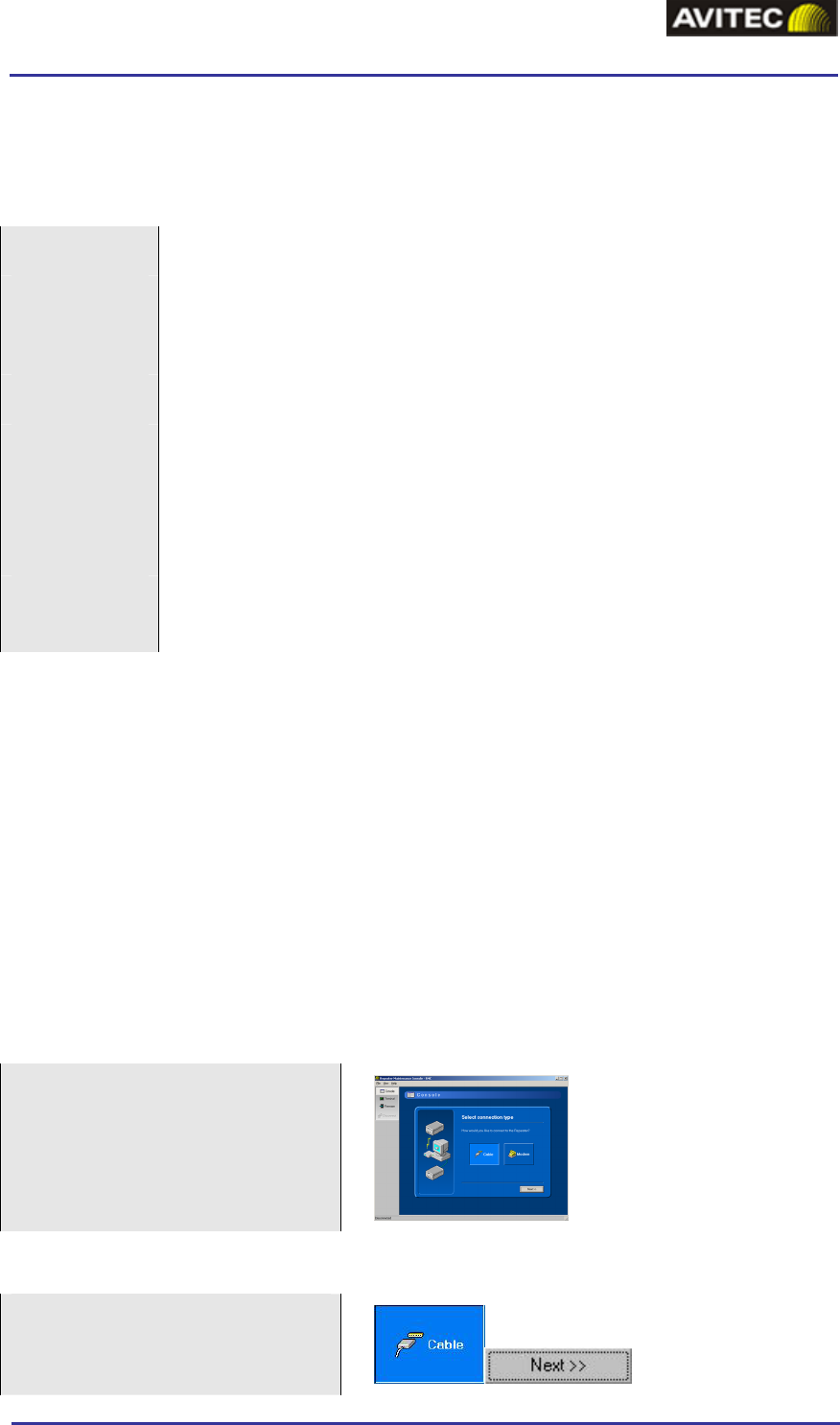
GSM-EDGE Repeaters
APPENDIX 2 – RMC SHORT GUIDE
Installation
Requirements
CPU Pentium, 200 MHz (Pentium III, 500 MHz recommended)
RAM 64 MB (128 MB recommended)
Hard Drive 10 MB free disk space
CD-ROM Required for installation
Video
resolution
800 x 600 with at least 15 bit color depth (approx. 32000 colors)
24 bit color depth (16.7 million colors) recommended
It is possible to run the program in 256 or 16 color modes, but colors
will appear distorted
Operating
system
Windows 98SE/NT/2000/XP
Installation Procedure
1. Ensure the computer and operation system complies with the requirements above.
2. Insert the CD-ROM into your CD-ROM reader. This will in most cases auto-start the
setup program. If not select your CD-ROM drive and double-click the file “Setup.exe”.
3. Follow the setup program guide through the installation process. Specify where the
program should be installed.
4. When the installation is finished, start the RMC from the” Start” menu (no reboot is
needed)
Connection Setup
At startup the “connection
wizard” is displayed. This wizard
contains a step-by-step guide
through the connection and login
process.
Cable Connection Set up
Click “Cable”
Click “Next”
© Avitec AB 11/12/2003 2 (6)
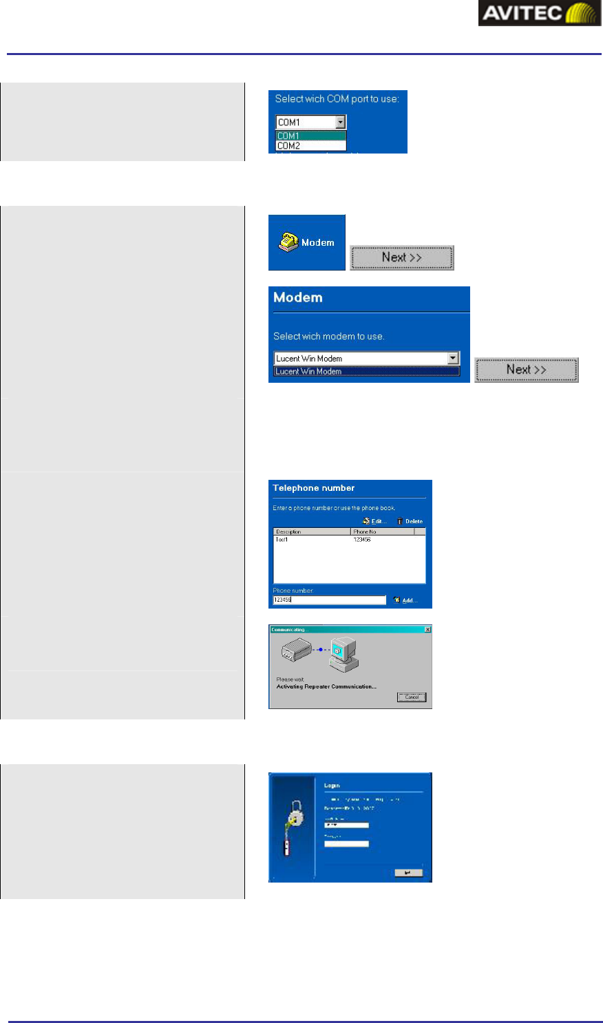
GSM-EDGE Repeaters
APPENDIX 2 – RMC SHORT GUIDE
Select the serial port to be used.
Click “Connect”
Modem Connection Set up
Click “Modem”
Click “Next”
Select the modem to use. The
RMC automatically receives a list
of available modems from the
Windows operation system.
Click “Next”
Note!
It is important that your modem is installed in
Windows according to the manual provided by the
modem manufacturer.
Enter the phone number. Type the
number or choose one from the
phone book.
Click “Connect” and wait for
connection to be established
Login
Enter username and password (for
Terminal view no login is
required).
Click “Next”
© Avitec AB 11/12/2003 3 (6)
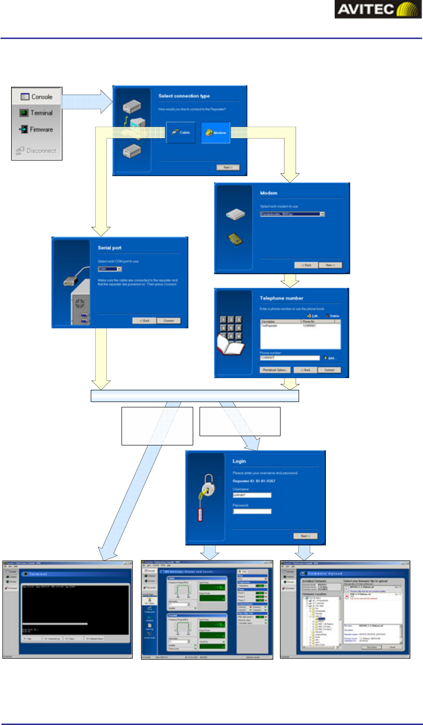
GSM-EDGE Repeaters
APPENDIX 2 – RMC SHORT GUIDE
Work Flow for Connection Set up
Choose if you want to connect
via cable or modem. Click Next.
Select modem
to use.
Click Next.
Select
serial port
to use.
Click
Next.
Enter the phone
number to dial
or select a
number from
the phone
book.
Click Next.
Enter username
and password.
Click Next.
Select desired
view
MODEMCABLE
If Console or Firmware
view is selected login is
required.
If Terminal view is
selected login is not
required.
CONNECTION ESTABLISHED
Terminal view Console view Firmware view
© Avitec AB 11/12/2003 4 (6)
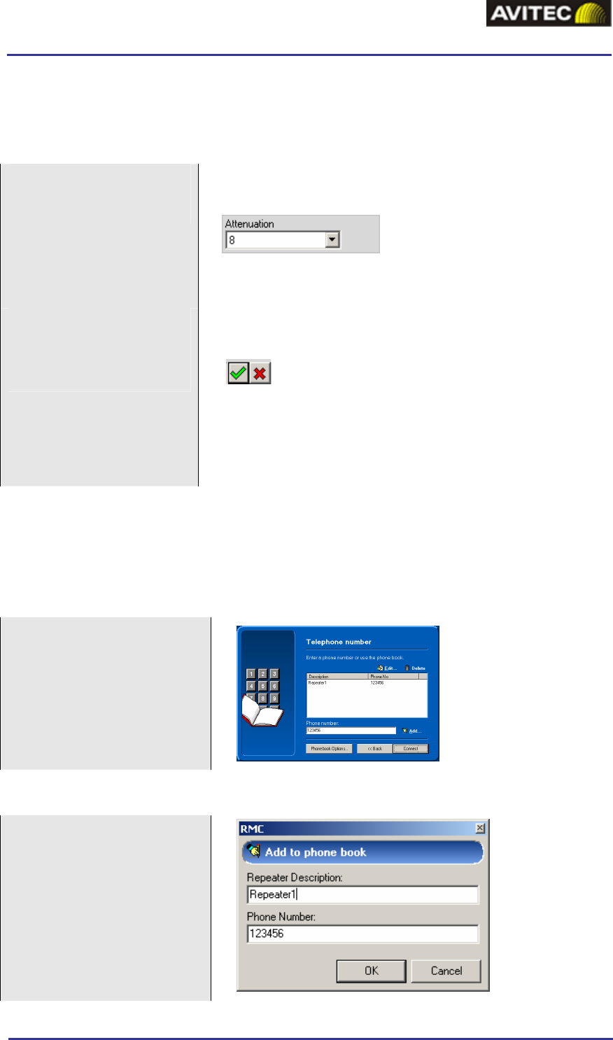
GSM-EDGE Repeaters
APPENDIX 2 – RMC SHORT GUIDE
How to Change a Parameter
There is a two step procedure to change a parameter in RMC.
Change the value
A value can be changed by typing it or by choosing a
value from a drop down menu
In this case there is a drop down menu. Click on ”b” to
the right of the box and chose a value.
Apply or cancel the
change
As soon as a change is made or a value is inserted this
symbol appears
The change is applied by clicking the green “accept
button”
The change is canceled by clicking the red cross (or by
pressing Esc)
How to Use the Phone Book
Modem phone numbers to can be stored in the RMC phone book. Each computer user is
allocated an individual RMC phonebook which is stored in the windows registry.
Initial screen
Add a Phone Number
Type the number in the
phone number edit box
Click “Add”
This brings up a dialog box
Enter a description of the
phonebook entry
Click “Ok”
© Avitec AB 11/12/2003 5 (6)
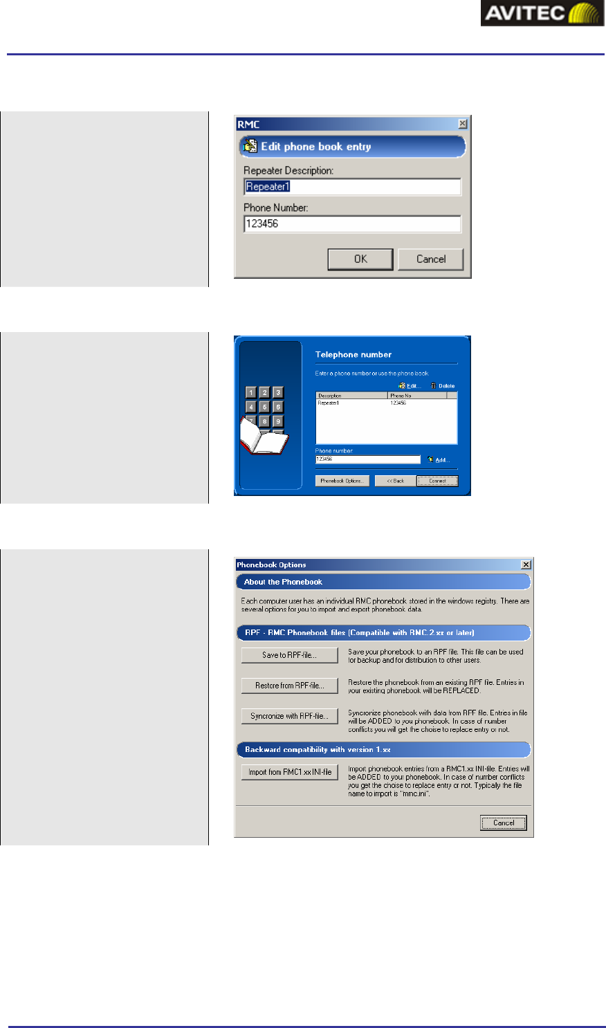
GSM-EDGE Repeaters
APPENDIX 2 – RMC SHORT GUIDE
Edit a Phone Number
Select a number in the list
Click “Edit”
This brings up a dialog box
Make the changes
Click “Ok”
Delete a Phone Number
Select a phone number in
the list
Click “Delete”
Confirm
Import/Export Phonebook Data
Click “Phonebook Options”
Choose between the options:
Save phonebook
Restore the phonebook
Synchronize phonebook
The file extension is RPF.
Files can be used in RMC
versions 2.00 and later.
Phonebook data from RMC
version 1.xx (INI-files) can
also be imported.
© Avitec AB 11/12/2003 6 (6)