AwarePoint RM1 RM1 User Manual
AwarePoint Corporation RM1
UserManual.wiki
>
AwarePoint
>
RM1 User Manual
User Manual
Navigation menu
Upload a User Manual
Namespaces
Wiki Guide
HTML
PDF
Info
Views
User Manual
Discussion / Help
Navigation
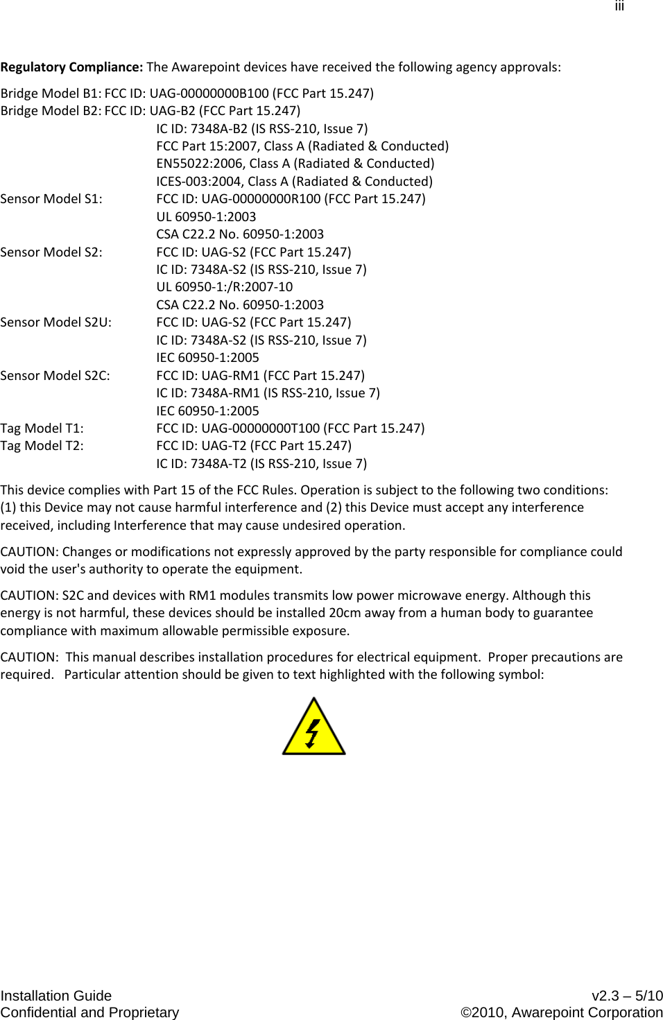

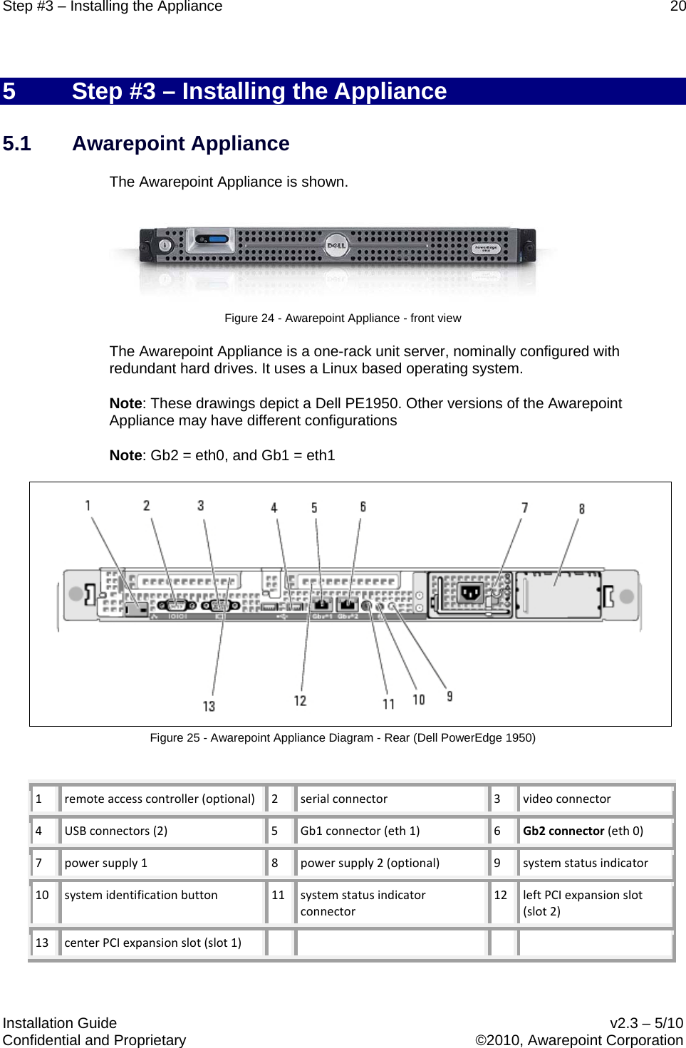
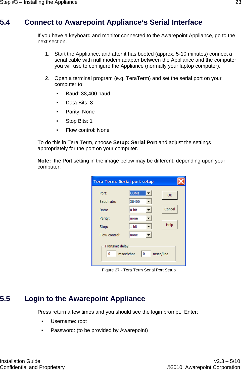
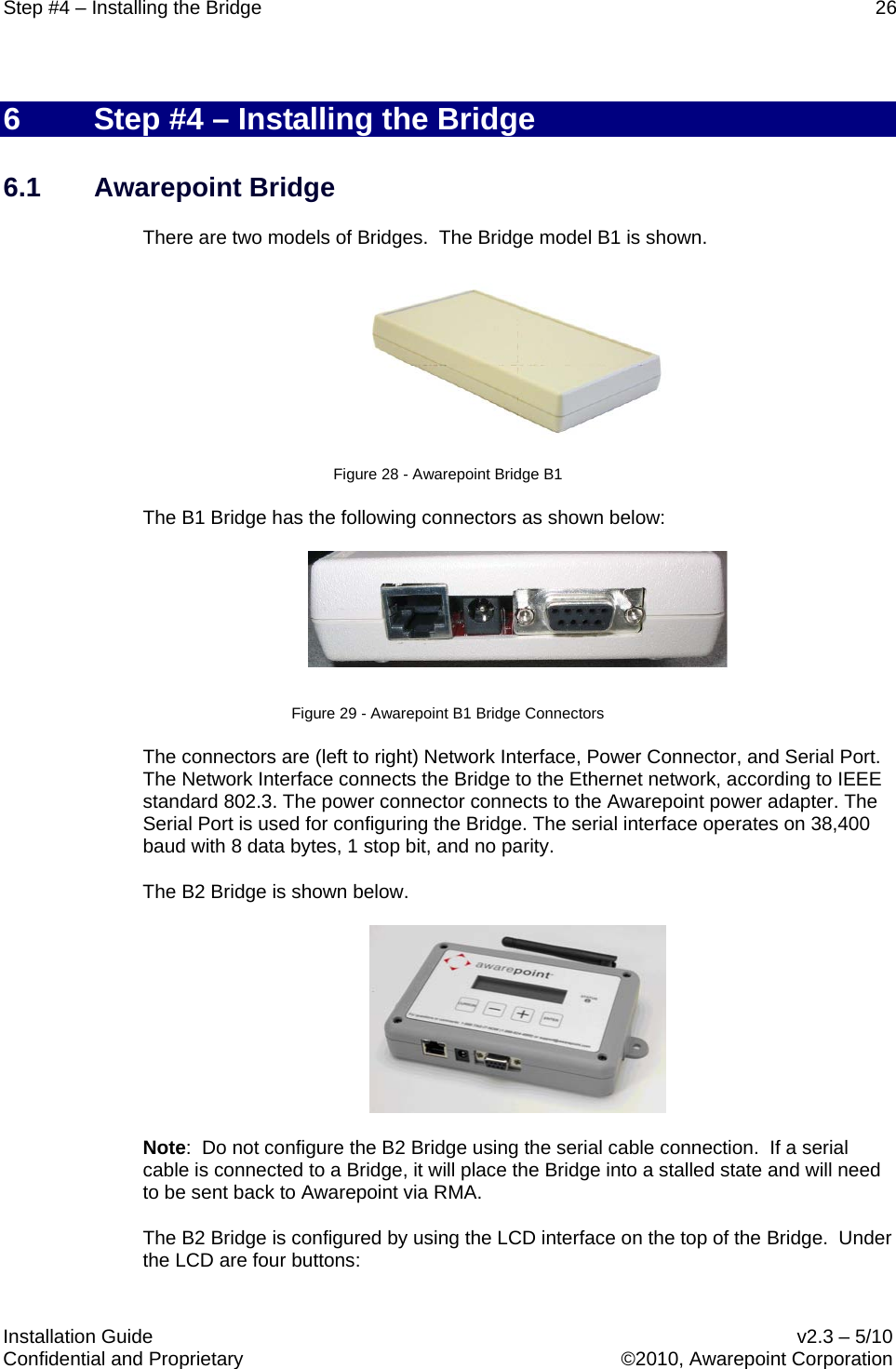
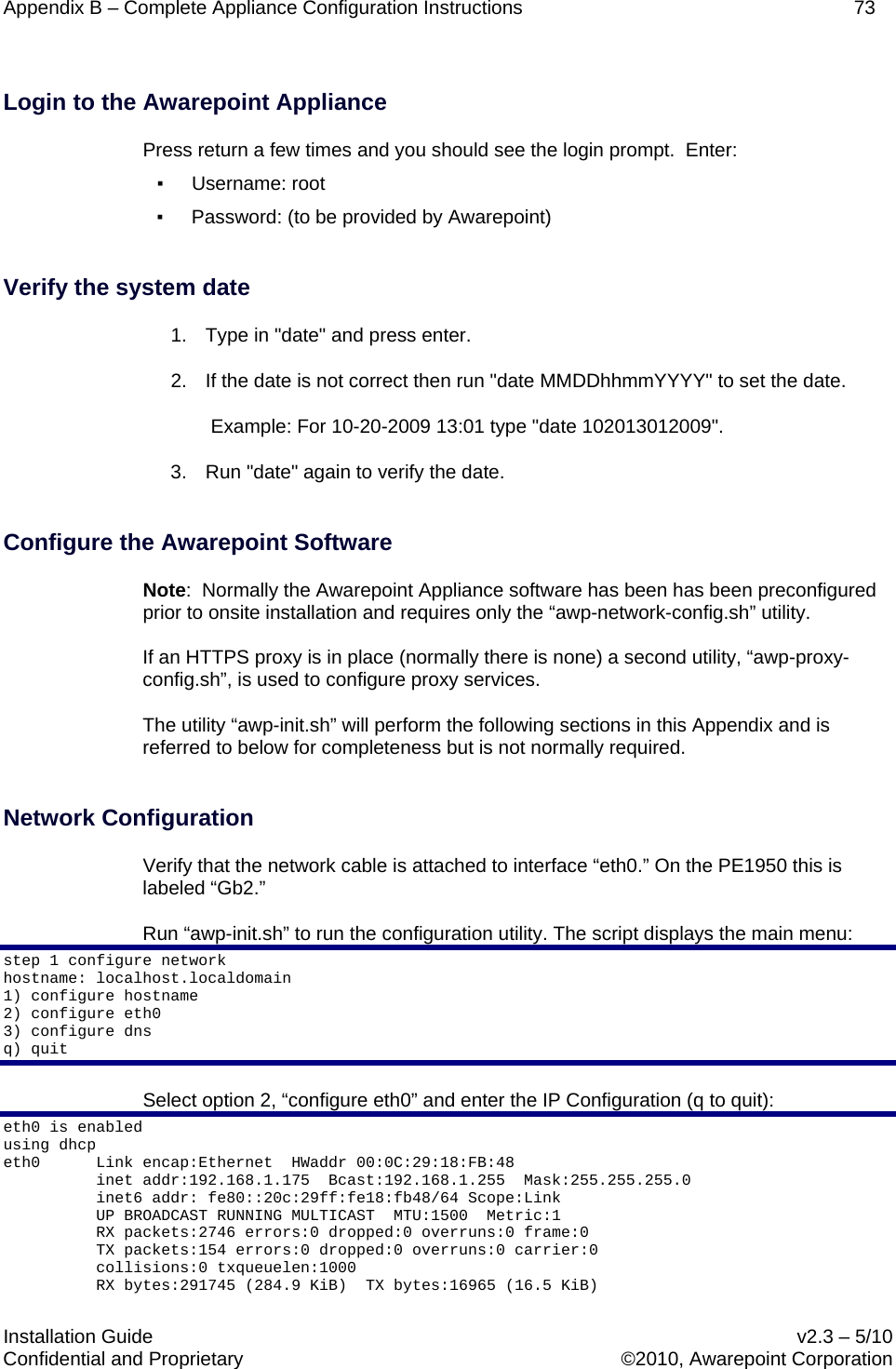
![Step #3 – Installing the Appliance 24 Installation Guide v2.3 – 5/10 Confidential and Proprietary ©2010, Awarepoint Corporation 5.6 Initial Set-up Run “awp-network-config.sh” to run the configuration utility. The script displays the main menu.: hostname: aps.awarepoint.com 1) configure hostname 2) configure eth0 3) configure dns 4) test network q) quit 5.7 Configure IP Address Select option 2, “configure eth0” eth0 is enabled using dhcp eth0 Link encap:Ethernet HWaddr 00:0C:29:18:FB:48 inet addr:192.168.1.175 Bcast:192.168.1.255 Mask:255.255.255.0 inet6 addr: fe80::20c:29ff:fe18:fb48/64 Scope:Link UP BROADCAST RUNNING MULTICAST MTU:1500 Metric:1 RX packets:2746 errors:0 dropped:0 overruns:0 frame:0 TX packets:154 errors:0 dropped:0 overruns:0 carrier:0 collisions:0 txqueuelen:1000 RX bytes:291745 (284.9 KiB) TX bytes:16965 (16.5 KiB) Interrupt:177 Base address:0x1400 1) Use DHCP 2) Manually configure 3) Restart interface 4) Enable Device 5) Disable Device q) quit ▪ If DHCP select option 1, “Use DHCP” ▪ If Static, select option 2, “Manually Configure,” and enter the Awarepoint Appliance’s IP address information. (Note: examples shown below) IP Address: 192.168.1.173 Netmask: 255.255.255.0 Gateway (default route): 192.168.1.1 Press “q” to return to the main menu. When asked to restart the network, choose yes (y). changes were made restart network [y/n]?](https://usermanual.wiki/AwarePoint/RM1/User-Guide-1283951-Page-34.png)
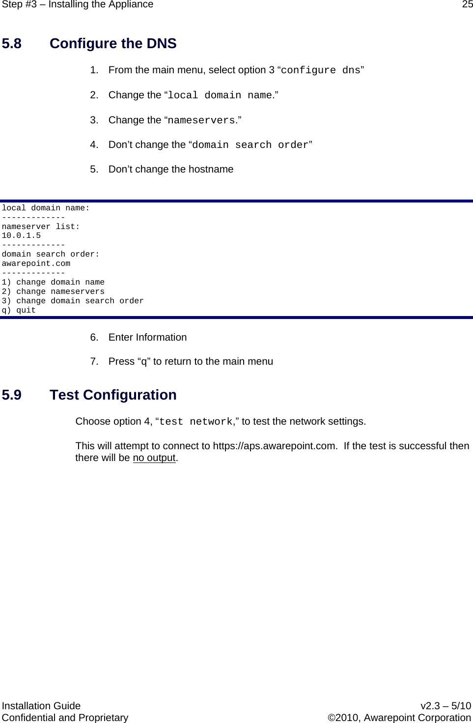
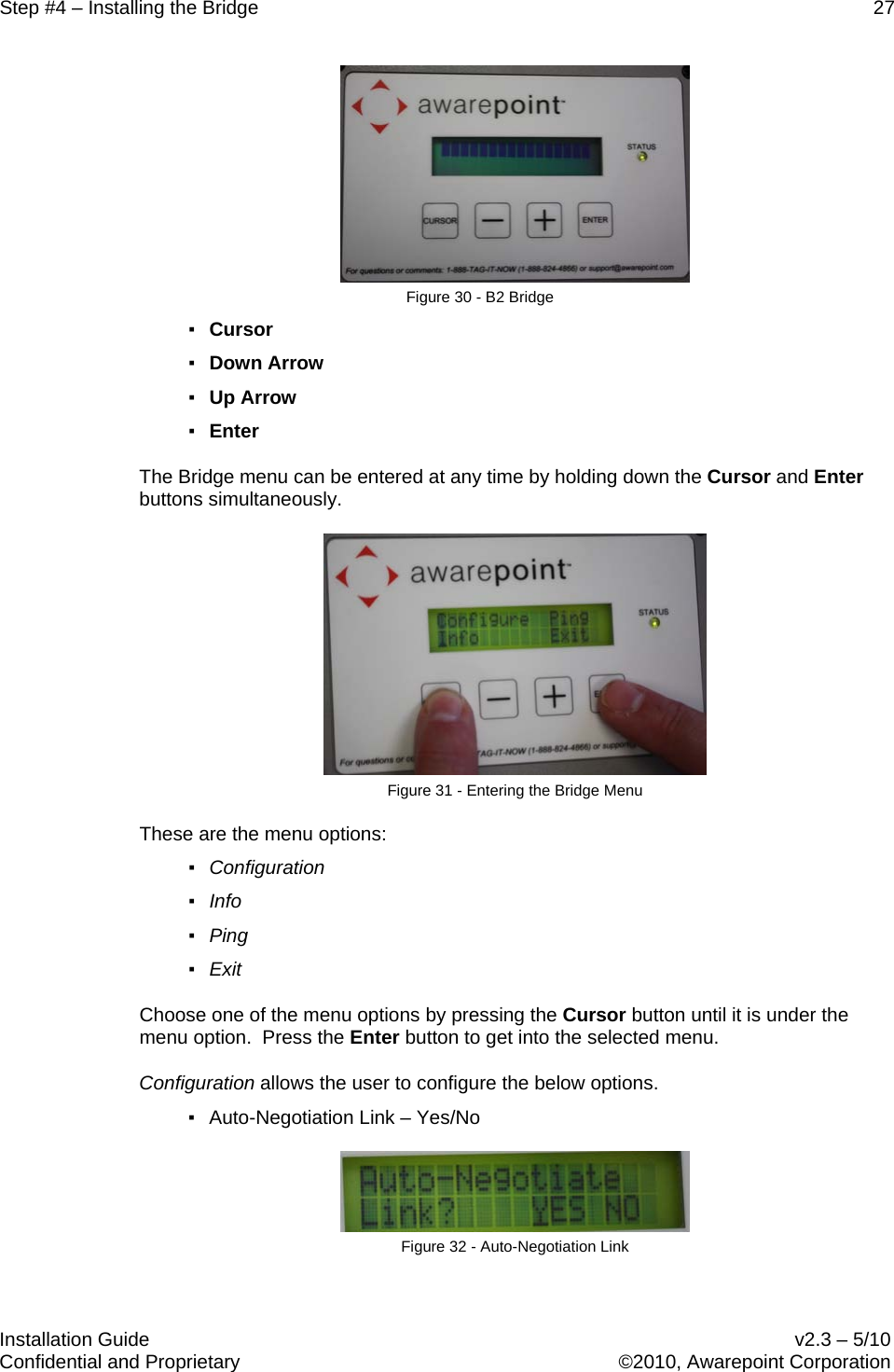
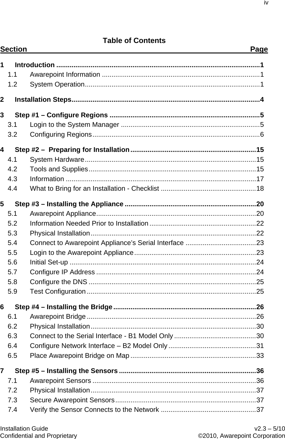
![Appendix B – Complete Appliance Configuration Instructions 74 Installation Guide v2.3 – 5/10 Confidential and Proprietary ©2010, Awarepoint Corporation Interrupt:177 Base address:0x1400 1) Use DHCP 2) Manually configure 3) Restart interface 4) Enable Device 5) Disable Device q) quit Select option 2, "Manually Configure," and enter the Awarepoint Appliance’s IP address information. IP Address: 192.168.1.173 Netmask: 255.255.255.0 Gateway (default route): 192.168.1.1 Press "q" to return to the main menu when asked. changes were made restart network [y/n]? Press “y.” Select option 3, "configure dns," and enter the IP address of the dns Awarepoint Appliance (q to quit): local domain name: ------------- nameAwarepoint Appliance list: 206.13.30.12 206.13.29.12 ------------- domain search order: localdomain ------------- 1) change domain name 2) change nameAwarepoint Appliances 3) change domain search order q) quit Select option 4, "test network," to test the network settings. This will attempt to connect to https://aps.awarepoint.com. If the test is successful there will be no output. You will need to check the network settings if you see something like this: Attempting to connect to https://aps.awarepoint.com curl: (7) couldn't connect to host Download Failed error #7. see |man curl| for more info. Press "q" to return to the main menu. Proxy Configuration If there is no HTTPS proxy (normally, there is none) then just press "q" to continue. Otherwise press "1" to set the proxy settings: step 2 configure proxy Proxy is not configured 1) change settings 2) disable proxy 3) test proxy settings q) exit 1](https://usermanual.wiki/AwarePoint/RM1/User-Guide-1283951-Page-84.png)