AwarePoint RM1 RM1 User Manual
AwarePoint Corporation RM1
User Manual

Awarepoint
Installation Guide
Version 2.3
Awarepoint Software
Version 6.4

i
Installation Guide v2.3 – 5/10
Confidential and Proprietary ©2010, Awarepoint Corporation
Change History
Version
Date
Description of Change
2.1
7/27/2009
Baseline release from previous versions. Changed paragraphs 7.1 and 7.2 to add
S2U information.
2.2
3/31/2010
Updated to include the S2C/RM1 information and rewrite the regulatory info on
sheet ii. Update appliance setup and make editorial comments throughout.
2.3
5/17/2010
Added Regulatory note OET Guide 65C. Updated with new Awarepoint Address
ii
Installation Guide v2.3 – 5/10
Confidential and Proprietary ©2010, Awarepoint Corporation
Copyright
Copyright 2010 Awarepoint Corporation, 600 W Broadway, Suite 250, San Diego, CA 92101
All rights reserved. This product or document is protected by copyright and distributed under licenses
restricting its use, copying, distribution, and decompilation. No part of this product or document may be
reproduced in any form by any means without prior written authorization of Awarepoint and its licensors,
if any.
Awarepoint, the Awarepoint logo, and Real-Tme Awareness Solution, are trademarks or registered
trademarks of Awarepoint Corporation in the United States and in other countries.
Microsoft is a registered trademark of Microsoft Corporation in the United States and/or other countries.
ZigBee is a trademark for the ZigBee Alliance.

iii
Installation Guide v2.3 – 5/10
Confidential and Proprietary ©2010, Awarepoint Corporation
Regulatory Compliance: The Awarepoint devices have received the following agency approvals:
Bridge Model B1: FCC ID: UAG-00000000B100 (FCC Part 15.247)
Bridge Model B2: FCC ID: UAG-B2 (FCC Part 15.247)
IC ID: 7348A-B2 (IS RSS-210, Issue 7)
FCC Part 15:2007, Class A (Radiated & Conducted)
EN55022:2006, Class A (Radiated & Conducted)
ICES-003:2004, Class A (Radiated & Conducted)
Sensor Model S1: FCC ID: UAG-00000000R100 (FCC Part 15.247)
UL 60950-1:2003
CSA C22.2 No. 60950-1:2003
Sensor Model S2: FCC ID: UAG-S2 (FCC Part 15.247)
IC ID: 7348A-S2 (IS RSS-210, Issue 7)
UL 60950-1:/R:2007-10
CSA C22.2 No. 60950-1:2003
Sensor Model S2U: FCC ID: UAG-S2 (FCC Part 15.247)
IC ID: 7348A-S2 (IS RSS-210, Issue 7)
IEC 60950-1:2005
Sensor Model S2C: FCC ID: UAG-RM1 (FCC Part 15.247)
IC ID: 7348A-RM1 (IS RSS-210, Issue 7)
IEC 60950-1:2005
Tag Model T1: FCC ID: UAG-00000000T100 (FCC Part 15.247)
Tag Model T2: FCC ID: UAG-T2 (FCC Part 15.247)
IC ID: 7348A-T2 (IS RSS-210, Issue 7)
This device complies with Part 15 of the FCC Rules. Operation is subject to the following two conditions:
(1) this Device may not cause harmful interference and (2) this Device must accept any interference
received, including Interference that may cause undesired operation.
CAUTION: Changes or modifications not expressly approved by the party responsible for compliance could
void the user's authority to operate the equipment.
CAUTION: S2C and devices with RM1 modules transmits low power microwave energy. Although this
energy is not harmful, these devices should be installed 20cm away from a human body to guarantee
compliance with maximum allowable permissible exposure.
CAUTION: This manual describes installation procedures for electrical equipment. Proper precautions are
required. Particular attention should be given to text highlighted with the following symbol:

iv
Installation Guide v2.3 – 5/10
Confidential and Proprietary ©2010, Awarepoint Corporation
Table of Contents
1 Introduction ........................................................................................................... 1
Section Page
1.1 Awarepoint Information ................................................................................... 1
1.2 System Operation ............................................................................................ 1
2 Installation Steps ................................................................................................... 4
3 Step #1 – Configure Regions ............................................................................... 5
3.1 Login to the System Manager ......................................................................... 5
3.2 Configuring Regions ........................................................................................ 6
4 Step #2 – Preparing for Installation .................................................................. 15
4.1 System Hardware .......................................................................................... 15
4.2 Tools and Supplies ........................................................................................ 15
4.3 Information .................................................................................................... 17
4.4 What to Bring for an Installation - Checklist .................................................. 18
5 Step #3 – Installing the Appliance ..................................................................... 20
5.1 Awarepoint Appliance .................................................................................... 20
5.2 Information Needed Prior to Installation ........................................................ 22
5.3 Physical Installation ....................................................................................... 22
5.4 Connect to Awarepoint Appliance’s Serial Interface ..................................... 23
5.5 Login to the Awarepoint Appliance ................................................................ 23
5.6 Initial Set-up .................................................................................................. 24
5.7 Configure IP Address .................................................................................... 24
5.8 Configure the DNS ........................................................................................ 25
5.9 Test Configuration ......................................................................................... 25
6 Step #4 – Installing the Bridge ........................................................................... 26
6.1 Awarepoint Bridge ......................................................................................... 26
6.2 Physical Installation ....................................................................................... 30
6.3 Connect to the Serial Interface - B1 Model Only ........................................... 30
6.4 Configure Network Interface – B2 Model Only .............................................. 31
6.5 Place Awarepoint Bridge on Map .................................................................. 33
7 Step #5 – Installing the Sensors ........................................................................ 36
7.1 Awarepoint Sensors ...................................................................................... 36
7.2 Physical Installation ....................................................................................... 37
7.3 Secure Awarepoint Sensors .......................................................................... 37
7.4 Verify the Sensor Connects to the Network .................................................. 37
v
Installation Guide v2.3 – 5/10
Confidential and Proprietary ©2010, Awarepoint Corporation
7.5 Place Awarepoint Sensor on Map ................................................................. 38
7.6 Optimize Awarepoint Sensor Locations ........................................................ 40
7.7 Deleting Unused Bridges and Sensors from System .................................... 41
8 Step #6 – Installing the Tags .............................................................................. 42
8.1 Awarepoint Tags ........................................................................................... 42
8.2 Batch Create Tags ........................................................................................ 42
8.3 Physical Installation ....................................................................................... 43
8.4 Temperature Tag ........................................................................................... 45
8.5 Sterilizable Tag .............................................................................................. 47
8.6 Optical Sensor Tag ........................................................................................ 50
9 Step #7 – Associating the Tags with Assets .................................................... 52
9.1 Accessing Infopoint ....................................................................................... 52
9.2 Adding Assets ............................................................................................... 53
9.3 Edit Assets .................................................................................................... 54
9.4 Delete Assets ................................................................................................ 55
9.5 View or edit asset types, manufacturers, models and owners ...................... 57
10 Step #8 – System Testing and Quality Control ................................................. 60
10.1 Awarepoint Sensors ...................................................................................... 60
10.2 Awarepoint Bridges ....................................................................................... 60
10.3 Awarepoint Tags ........................................................................................... 60
10.4 Accuracy Testing ........................................................................................... 60
11 Adding Additional Assets After Installation ..................................................... 62
11.1 System Manager ........................................................................................... 62
11.2 Add an Asset to an Existing Asset Type ....................................................... 64
11.3 Add a New Asset Type .................................................................................. 66
11.4 Find an existing asset .................................................................................... 67
12 Troubleshooting .................................................................................................. 68
12.1 Awarepoint Appliance .................................................................................... 68
12.2 Awarepoint Bridge ......................................................................................... 68
12.3 Awarepoint Sensor ........................................................................................ 69
12.4 Awarepoint Tag ............................................................................................. 69
Appendix A – Awarepoint Bridge Web Interface ...................................................... 70
Appendix B – Complete Appliance Configuration Instructions ............................. 72
Connect to Awarepoint Appliance’s Serial Interface ................................................. 72
Login to the Awarepoint Appliance ............................................................................ 73
Verify the system date ............................................................................................... 73
vi
Installation Guide v2.3 – 5/10
Confidential and Proprietary ©2010, Awarepoint Corporation
Configure the Awarepoint Software .......................................................................... 73
Network Configuration ............................................................................................... 73
Proxy Configuration ................................................................................................... 74
Mysql Password Generation ..................................................................................... 75
Root Password .......................................................................................................... 75
Time zone Configuration ........................................................................................... 75
Network Operations Center Registration .................................................................. 76
Test the Awarepoint Appliance ................................................................................. 76
Appendix C – Server Error Codes ............................................................................. 77

vii
Installation Guide v2.3 – 5/10
Confidential and Proprietary ©2010, Awarepoint Corporation
Table of Figures
Figure Page
Figure 1 - System Diagram ............................................................................................... 2
Figure 2 - Launch System Manager .................................................................................. 5
Figure 3 - System Manager Login ..................................................................................... 5
Figure 4 - System Manager home ..................................................................................... 6
Figure 5 - System Manager Positioning Tab ..................................................................... 7
Figure 6 - New Campus Dialog Box .................................................................................. 7
Figure 7 - Campus Created ............................................................................................... 8
Figure 8 - New Building Dialog Box .................................................................................. 8
Figure 9 - Building Created ............................................................................................... 8
Figure 10 - New Floor Dialog Box ..................................................................................... 9
Figure 11 - Floor Created .................................................................................................. 9
Figure 12 - Open Image Dialog Box ................................................................................ 10
Figure 13 - Floor Image Loaded ...................................................................................... 10
Figure 14 - Drawing an Area ........................................................................................... 11
Figure 15 - New Room Dialog Box .................................................................................. 11
Figure 16 - Area Created ................................................................................................ 11
Figure 17 - Positioning: Areas Tab .................................................................................. 12
Figure 18 - Set Polygonal Area ....................................................................................... 12
Figure 19 - Valid Area ..................................................................................................... 13
Figure 20 - Complete Area .............................................................................................. 13
Figure 21 - Naming the New Area ................................................................................... 13
Figure 22 - Setting Map Scale ......................................................................................... 14
Figure 23 - Enter Segment Length .................................................................................. 14
Figure 24 - Awarepoint Appliance - front view ................................................................ 20
Figure 25 - Awarepoint Appliance Diagram - Rear (Dell PowerEdge 1950) ................... 20
Figure 26 - Awarepoint Appliance Diagram - Front (Dell PowerEdge 1950) ................... 21
Figure 27 - Tera Term Serial Port Setup ......................................................................... 23
Figure 28 - Awarepoint Bridge B1 ................................................................................... 26
Figure 29 - Awarepoint B1 Bridge Connectors ................................................................ 26
Figure 30 - B2 Bridge ...................................................................................................... 27
Figure 31 - Entering the Bridge Menu ............................................................................. 27
Figure 32 - Auto-Negotiation Link ................................................................................... 27
Figure 33 - DHCP option ................................................................................................. 28
Figure 34 - Static IP Address .......................................................................................... 28
Figure 35 - Subnet Mask ................................................................................................. 28
Figure 36 - Default Gateway ........................................................................................... 28
Figure 37 - Auto Discover Server .................................................................................... 28
Figure 38 - Bridge Connected to the Appliance .............................................................. 29
Figure 39 - Bridge Information ........................................................................................ 29
Figure 40 - Tera Term Serial Port Setup ......................................................................... 30
Figure 41 - B2 Enter for Settings & Tools ....................................................................... 31
Figure 42 - B2 Menu ....................................................................................................... 31
Figure 43 - Auto-Negotiation Link ................................................................................... 32
Figure 44 - DHCP option ................................................................................................. 32
Figure 45 - Auto Discover Server .................................................................................... 32
Figure 46 - Save Settings for B2 Bridge .......................................................................... 32
Figure 47 - No Settings Were Changed .......................................................................... 33
viii
Installation Guide v2.3 – 5/10
Confidential and Proprietary ©2010, Awarepoint Corporation
Figure 48 – Bridge Icons ................................................................................................. 33
Figure 49 - Placing Awarepoint Bridge ............................................................................ 34
Figure 50 - Placing Awarepoint Bridge Using B Button .................................................. 34
Figure 51 - R1 Sensor ..................................................................................................... 36
Figure 52 - S2 Sensor ..................................................................................................... 36
Figure 53 - S2U Sensor .................................................................................................. 36
Figure 54 - Placing Awarepoint Sensors ......................................................................... 38
Figure 55 - Placing Awarepoint Sensors using S button ................................................. 39
Figure 56 - Adding Comments to Sensors ...................................................................... 39
Figure 57 - Placing All Awarepoint Sensors .................................................................... 40
Figure 58- Bowtie Network .............................................................................................. 40
Figure 59 – Sensors and Signal Strength ....................................................................... 41
Figure 60 - T1 Tag .......................................................................................................... 42
Figure 61 - T2-A Tag ....................................................................................................... 42
Figure 62 - Batch Create Tags in Status Server ............................................................. 43
Figure 63 - Tag Zip Tie Attachment ................................................................................ 44
Figure 64 - Tag Double-Sided Tape Attachment ............................................................ 44
Figure 65 - Creating Temperature Tag Mode ................................................................. 45
Figure 66 - Assigning Tags to a Mode ............................................................................ 46
Figure 67 - Temperature Tag Installation with Service Loop .......................................... 47
Figure 68 - Autoclave Tag ............................................................................................... 47
Figure 69 - Autoclave Tag on Outside of Tray ................................................................ 47
Figure 70 - Autoclave Tag in Bracket .............................................................................. 48
Figure 71 - Autoclave Tag Removed from Bracket ......................................................... 48
Figure 72 - Creating Sterilizable Tag Mode .................................................................... 49
Figure 73 - Assigning Tags to a Mode ............................................................................ 49
Figure 74 - Sterilizable Tag Installation ........................................................................... 50
Figure 75 - Infopoint Login .............................................................................................. 52
Figure 76 - Infopoint Main Page ...................................................................................... 53
Figure 77 - Assets Tab .................................................................................................... 53
Figure 78 - Manage Assets ............................................................................................. 53
Figure 79 - Asset Information .......................................................................................... 54
Figure 80 - Tag MAC drop-down list ............................................................................... 54
Figure 81 - Manage Assets ............................................................................................. 57
Figure 82 - Accuracy Testing in Status Server ................................................................ 61
Figure 83 - Viewing Accuracy Test Results .................................................................... 61
Figure 84 - Download System Manager .......................................................................... 62
Figure 85 - System Manager Login ................................................................................. 62
Figure 86 - Asset Manager .............................................................................................. 64
Figure 87 - Asset Type properties ................................................................................... 64
Figure 88 - Asset Properties ........................................................................................... 65
Figure 89 - List of Tags ................................................................................................... 65
Figure 90 - Offline Asset Manager .................................................................................. 66
Figure 91 - New Asset Type dialog box .......................................................................... 66
Figure 92 - Offline Asset Manager
.................................................................................. 67
Figure 93 - Find Assets dialog box .................................................................................. 67
Figure 94- Awarepoint Bridge Web Interface .................................................................. 70
Figure 95 - Awarepoint Bridge Password Prompt Dialog Box ......................................... 70
Figure 96 - Awarepoint Bridge Statistics Page ................................................................ 71
Figure 97 - Tera Term Serial Port Setup ......................................................................... 72
ix
Installation Guide v2.3 – 5/10
Confidential and Proprietary ©2010, Awarepoint Corporation

Introduction 1
Installation Guide v2.3 – 5/10
Confidential and Proprietary ©2010, Awarepoint Corporation
1 Introduction
This system installation manual is for use by an Awarepoint employee or Awarepoint
trained service provider who intends to install the Awarepoint Real-time Awareness
Solution.
This document describes how to install the Awarepoint Real-time Awareness Solution.
This allows users to easily locate tagged equipment using any web browser (Internet
Explorer, Mozilla Firefox, etc.).
The Awarepoint Real-time Awareness Solution is a suite of software and hardware that
can track the location, status and movement of Awarepoint tagged equipment and
people inside a facility. The system software consists of Awarepoint Appliance resident
software and various applications that are accessible from any web browser. The
system hardware consists of an Awarepoint Appliance, Awarepoint Bridges,
Awarepoint Sensors, and Awarepoint Tags.
1.1 Awarepoint Information
Contact Awarepoint for further information.
Fax: (858) 535-1808
Toll-Free: 1-888-TAG-IT-NOW (888-824-4866)
www.awarepoint.com
Email Awarepoint:
support@awarepoint.com
1.1.1 Document Conventions
Button names will be bold.
Menu items will be in italics
Tabs will be in italics.
1.2 System Operation
The Awarepoint Real-time Awareness Solution consists of several components as
shown in the diagram below. The parts of the system that require installation include
Awarepoint Tags, Awarepoint Sensors, Awarepoint Bridges, and the Awarepoint
Appliance. The Awarepoint Appliance contains all software necessary for system
operation.

Introduction 2
Installation Guide v2.3 – 5/10
Confidential and Proprietary ©2010, Awarepoint Corporation
Figure 1 - System Diagram
The Tag is a wireless device that is attached to equipment so that the equipment may
be located by the Awarepoint system. Although Tags attach to the asset in a variety of
ways, they are most commonly attached by zip-ties or high strength double-sided tape.
The Tags broadcast short messages periodically. If the Tag is moving, the default
update rate is seconds. If it is stationary, the default update rate is 10 minutes. These
values may be changed in the System Manager application.
The Sensors receive the messages broadcast by Tags. The Sensor measures the
signal strength received from the pulse (message), and transmits this data (Tag ID and
signal strength emitted from the Tag) to the Bridge. If the Bridge is not within direct
range of the Sensor, the Sensor sends the data to another Sensor and so forth until it
reaches the Bridge. In this manner, the Sensors form the Awarenet wireless mesh
network. This network is “self-healing” so if a Sensor is removed or otherwise
compromised, other Sensors will route around it. Sensors also periodically broadcast
messages to each other. These Sensor messages are used to calibrate the positioning
engine.
The Bridge connects the Awarenet wireless mesh network with the Awarepoint
Appliance via the facility’s Local Area Network (LAN). The Bridge contains a wireless
network interface similar to what is inside the Sensor as well as a wired Ethernet
interface. The B1 Bridge is configured with a serial interface. The B2 Bridge is
equipped with an LCD menu interface for configuration (do not use the serial interface
on the B2 Bridge).
Tags, Sensors, and Bridges also periodically check the Awarepoint Appliance for
updated configuration information or firmware updates. All three products can remotely
update their firmware.
Introduction 3
Installation Guide v2.3 – 5/10
Confidential and Proprietary ©2010, Awarepoint Corporation
The System is configured using the System Manager, a Java application that runs on a
PC connected to the facility LAN. The System Manager may be downloaded from the
Awarepoint Appliance or from the Network Operations Center.

Installation Steps 4
Installation Guide v2.3 – 5/10
Confidential and Proprietary ©2010, Awarepoint Corporation
2 Installation Steps
To meet your goal of performing a successful Awarepoint installation, carry out the
following steps in this order.
Step #1 Configuring Areas
Step #2 Preparing for Installation
Step #3 Installing the Appliance
Step #4 Installing the Bridge
Step #5 Installing the Sensors
Step #6 Installing the Tags
Step #7 Associating Tags with Assets
Step #8 System Testing and Quality Control
Step #1 – Configure Regions 5
Installation Guide v2.3 – 5/10
Confidential and Proprietary ©2010, Awarepoint Corporation
3 Step #1 – Configure Regions
Normally this step is performed first. Maps are created, loaded and configured before
the physical installation begins at the customer site.
It is extremely important to determine the areas ahead of time. Each floor area needs
to be discussed with the customer before beginning this step. If the customer asks for
areas to be reconfigured after the initial configuration, the rooms will have to be deleted
and redrawn, which is difficult and very time consuming. Planning ahead will optimize
your time and your relationship with the customer.
You must have a digital map of the facility in one of the following formats: JPG, GIF,
PNG. PNG is preferred, with dimensions of 2500 x 2500 pixels. The recommended
image size is 2-4 MB, but must be less than 8 MB.
3.1 Login to the System Manager
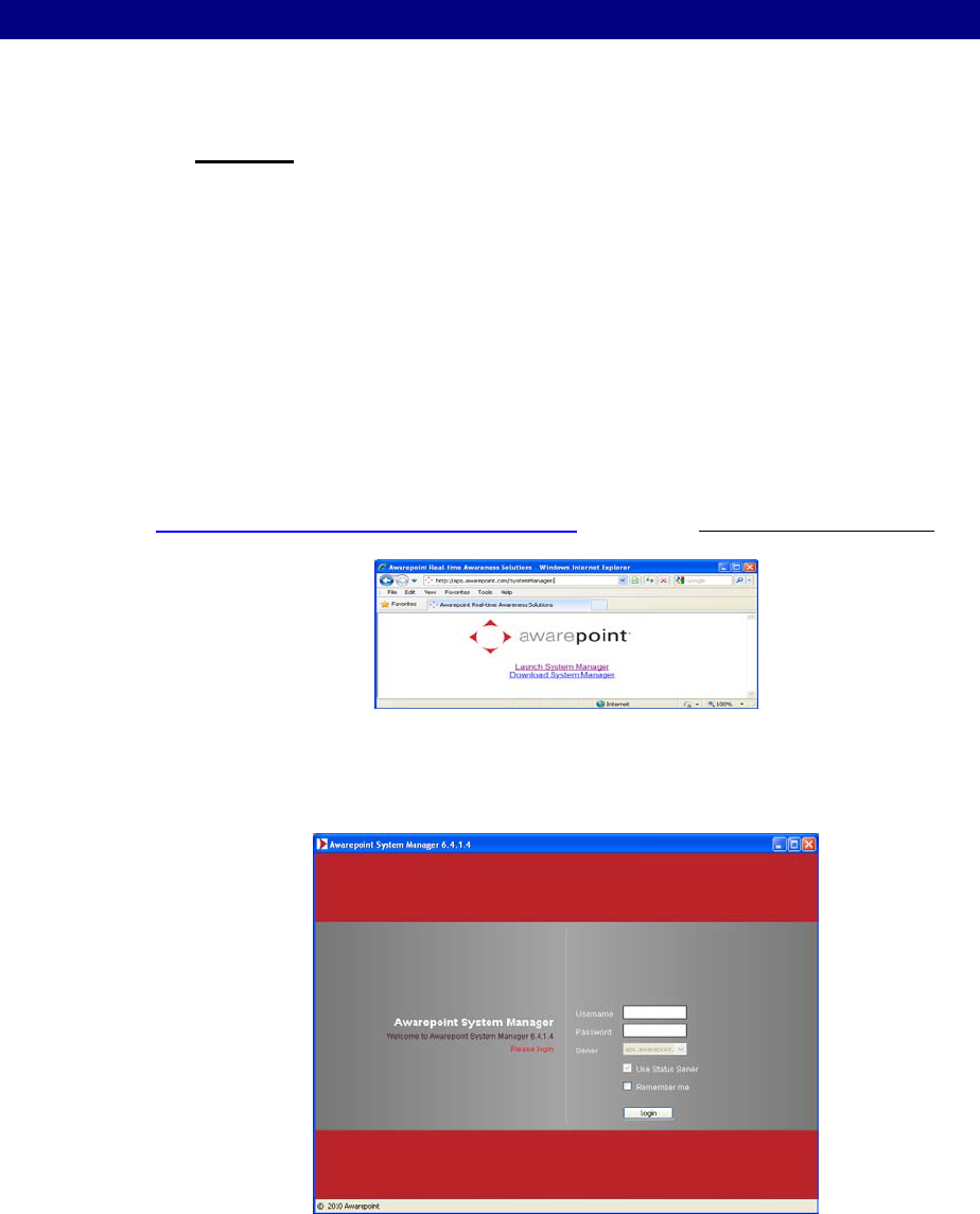
Access System Manager via the Network Operations Center (NOC). This can be done
without being on the Local Network. To do this, open a web browser and Navigate to
http://aps.awarepoint.com/SystemManager and choose Launch System Manager.
Figure 2 - Launch System Manager
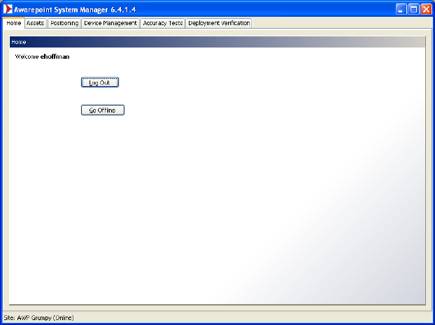
At the login screen, enter your Awarepoint Network Operations Center username and
password.
Figure 3 - System Manager Login
Choose the Login button.
Step #1 – Configure Regions 6
Installation Guide v2.3 – 5/10
Confidential and Proprietary ©2010, Awarepoint Corporation
3.1.1 System Manager Home
After you login, you should see the System Manager home screen:
Figure 4 - System Manager home
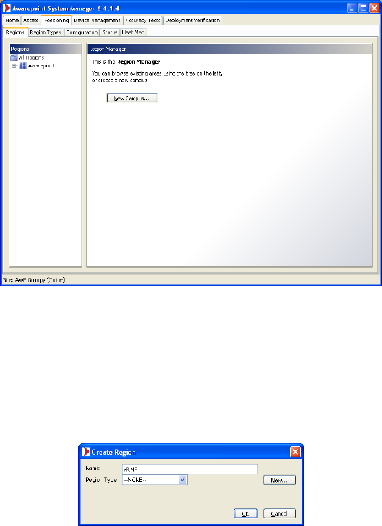
3.2 Configuring Regions
Under the Positioning tab, choose the Reigions tab to configure Regions. The
Awarepoint System Manager uses a Campus/Building/Floor/Region/Room hierarchy.
The first three levels of the hierarchy are required; the last two are optional.
Note: The screenshots show other campuses in the system for demonstration
purposes only. Your system should not have any other campuses defined.
Step #1 – Configure Regions 7
Installation Guide v2.3 – 5/10
Confidential and Proprietary ©2010, Awarepoint Corporation
Figure 5 - System Manager Positioning Tab
3.2.1 Creating a Campus
Choose the New Campus button to create a campus. Enter the name of the Campus
(in this example, “VRMF”) and choose OK.
Figure 6 - New Campus Dialog Box
Select the campus you created (VRMF) in the tree:
Step #1 – Configure Regions 8
Installation Guide v2.3 – 5/10
Confidential and Proprietary ©2010, Awarepoint Corporation
Figure 7 - Campus Created
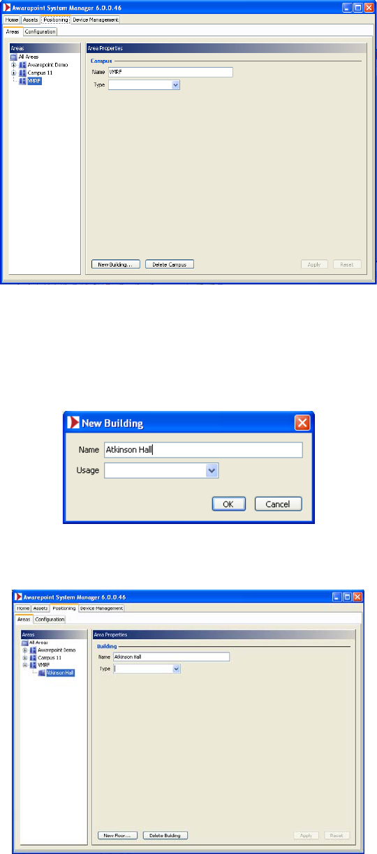
3.2.2 Creating a Building
Choose the New Building button. Enter the name of the Building (in this example,
“Atkinson Hall”) and choose OK.
Figure 8 - New Building Dialog Box
Select the building you created.
Figure 9 - Building Created
Step #1 – Configure Regions 9
Installation Guide v2.3 – 5/10
Confidential and Proprietary ©2010, Awarepoint Corporation
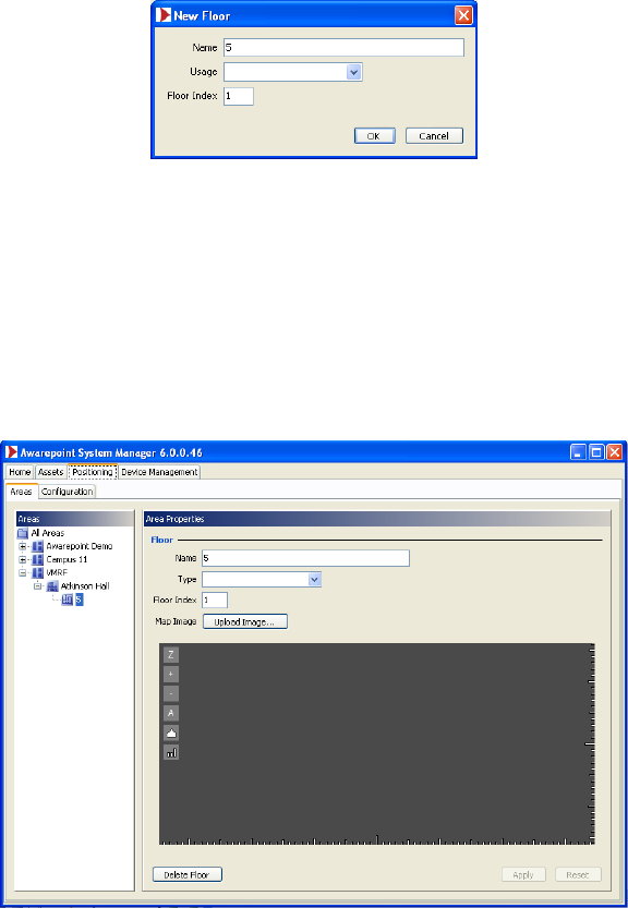
3.2.3 Creating a Floor
Choose the New Floor button. Enter the name of the Floor (in this example “5”) and
choose OK.
Figure 10 - New Floor Dialog Box
Choose the Usage type from the drop-down list. Some typical usage types include
Psych Floor or Intensive Care.
Enter a floor index. The floor index indicates the order the floors will appear in System
Manager and Status Server. Without a floor index defined, the floors will be sorted
alphabetically by the floor name.
Select the floor you created.
Figure 11 - Floor Created
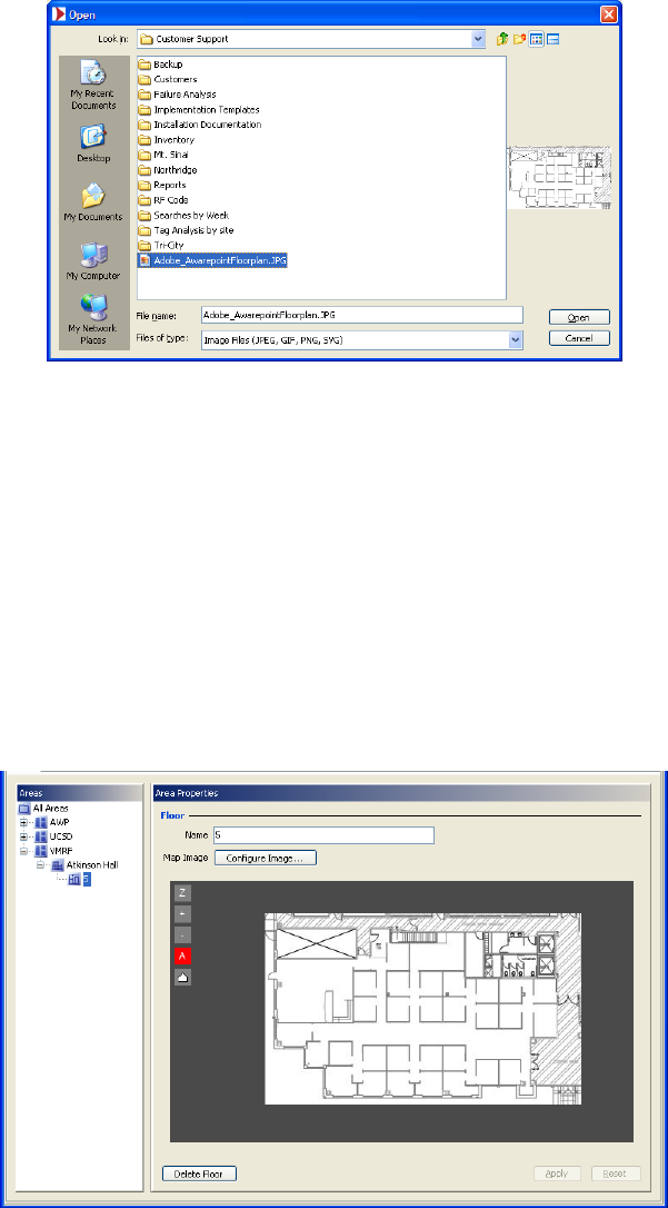
3.2.4 Importing an Image for a Floor
Choose the Upload Image button and navigate to the digital map of this floor.
The best way to ensure that the map can be easily located is to save the desired map
to the desktop on the computer being used; then, when searching for the map, simply
click desktop and the map can be accessed.
Step #1 – Configure Regions 10
Installation Guide v2.3 – 5/10
Confidential and Proprietary ©2010, Awarepoint Corporation
Figure 12 - Open Image Dialog Box
Choose the Open button to select the image.
3.2.5 Creating a Region for a Floor
The Awarepoint Appliance will only compute locations inside areas. Therefore, the
entire floor must be covered with contiguous areas if you want Tags to be positioned on
the floor. You may either draw in multiple areas or draw one area to cover the entire
floor.
Areas may be created with either the Rectangular Area tool or the Polygonal Area tool.
Select the floor you created and choose the Rectangular Area button:
Figure 13 - Floor Image Loaded
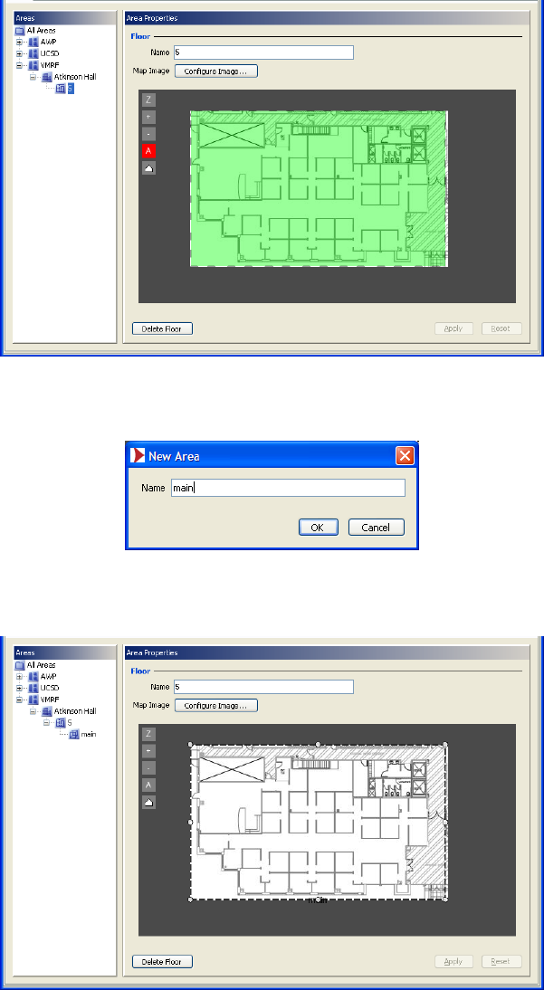
To create a new area, draw an area surrounding the entire floor. (You could also draw
any part of the area with the rectangular tool, if the shape permits.)
Step #1 – Configure Regions 11
Installation Guide v2.3 – 5/10
Confidential and Proprietary ©2010, Awarepoint Corporation
Figure 14 - Drawing an Area
Give the area a meaningful name such as “main.” Choose OK.
Figure 15 - New Room Dialog Box
At the main screen, choose the Apply button.
Figure 16 - Area Created
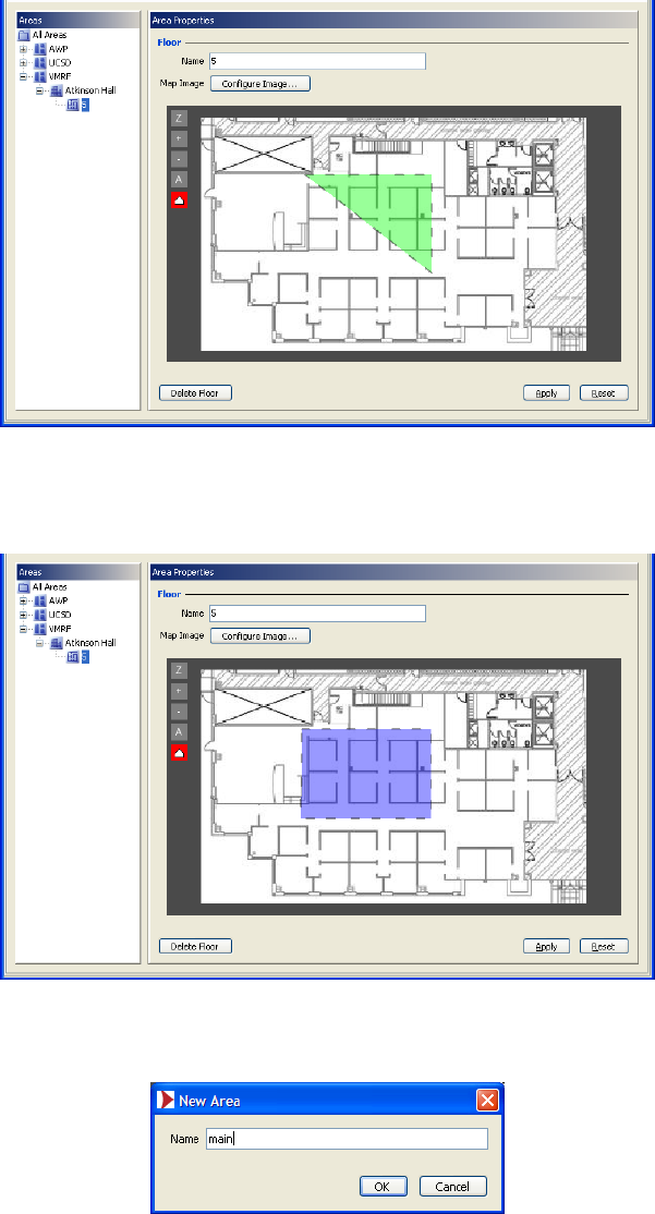
To create a polygonal area, choose the Polygonal Area tool button.
Step #1 – Configure Regions 12
Installation Guide v2.3 – 5/10
Confidential and Proprietary ©2010, Awarepoint Corporation
Figure 17 - Positioning: Areas Tab
Click on the map to set each vertex of the polygonal area.
Figure 18 - Set Polygonal Area
The green area indicates the outline of the area. If the area is red then it is not valid
because it overlaps with other areas.
Step #1 – Configure Regions 13
Installation Guide v2.3 – 5/10
Confidential and Proprietary ©2010, Awarepoint Corporation
Figure 19 - Valid Area
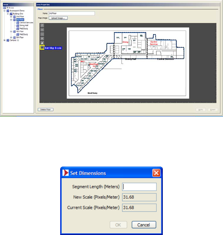
To complete the area, click on the starting point. The area will change color to blue
when the mouse is over the starting point.
Figure 20 - Complete Area
After you have completed the area, enter a name for the area.
Figure 21 - Naming the New Area
Note: Tags will only show up inside areas – you must draw area(s) on the floor where
Tags will travel.
Step #1 – Configure Regions 14
Installation Guide v2.3 – 5/10
Confidential and Proprietary ©2010, Awarepoint Corporation
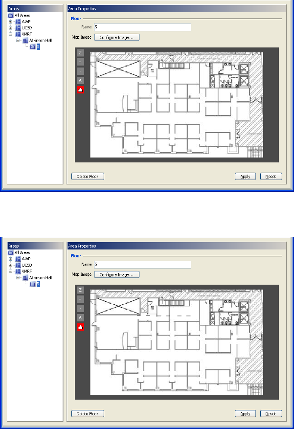
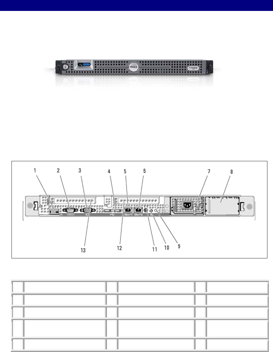
3.2.6 Setting Map Scale
For each floor in the facility, using a laser distance reader, select the longest
measurable distance and measure this distance in meters. Record this distance.
Open the System Manager and choose the Areas tab. Load the map of the floor to be
scaled. On the left side of the map, choose the bottom button Set Map Scale.
Figure 22 - Setting Map Scale
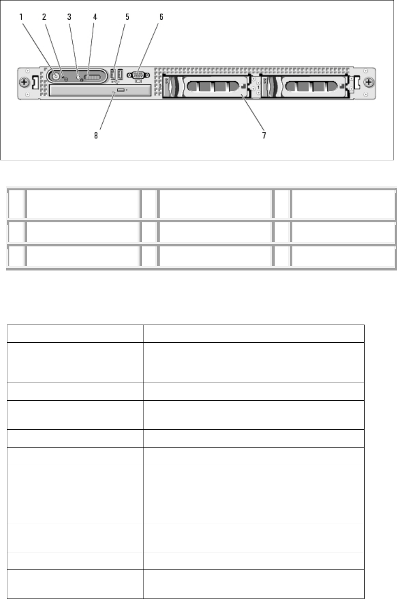
Find the area on the map where the distance was measured. Click on one end of the
measured length. While holding down the mouse button, drag the dotted line to the
other end of the measured distance. Release the mouse button. Enter the segment
length in meters.
Figure 23 - Enter Segment Length

Step #2 – Preparing for Installation 15
Installation Guide v2.3 – 5/10
Confidential and Proprietary ©2010, Awarepoint Corporation
4 Step #2 – Preparing for Installation
4.1 System Hardware
Prior to installation, you will need the following system hardware.
1. Awarepoint Appliance, including:
• Y Power Cable
• Rack Rails with mounting screws
• Bezel
• Ethernet Cable (Cat 5 or better, length to be determined by site
requirements)
2. Awarepoint Bridge(s), including:
• Power Supply
• Ethernet Cable (Cat 3 or better, length to be determined by site
requirements)
– Plug in the ethernet cable and then power.
– If the bridge is a B2 bridge and the network is capable of power over
Ethernet, the power adaptor is not required.
3. Awarepoint Sensors
4. Awarepoint Tags
If you have any questions about current firmware versions for the hardware, please
contact an Awarepoint Professional Services engineer.
4.2 Tools and Supplies
Hardware Tools Purpose
Laptop Computer
Barcode Reader Assist with tagging assets
Assist with capturing Sensor MACs and Bridge
MACs for batch create process
Network Analyzer Troubleshoot Bridge network ports and server
connection
Stainless Steel Zip tie Tool Cinch up the zip ties for secure Sensors and
Tags.

Step #2 – Preparing for Installation 16
Installation Guide v2.3 – 5/10
Confidential and Proprietary ©2010, Awarepoint Corporation
Hardware Tools Purpose
Security Screw Screwdriver Screwing in secure screws into the modified
electrical outlet faceplate for deploying secure
Sensors.
Torque Screwdriver Used when attaching T2S clips and brackets
Multi-head Screwdriver Flat head and Phillips (could only need heads)
Network Cable - 15'
Network Cable- 3'
Network Cable - 7'
Laser Distance Measure To determine a distance reference for entering
Map Scale into System Manager. Recommend a
device capable of reading distances of up to 150
feet.
Wire Cutters For trimming plastic zip ties for Tags and Bridge
installation.
Aluminum Foil Tape and/or Stickers Used when deploying Tags for Tag removal alerts
Network Switch Can be used for deployment team to connect to
network.
Flashlight
Powerstrip
Serial Cable (USB or 9 pin) Needed to configure B1 Bridges and Connect
Server (must have null modem adaptor for server
connections).
USB is usually needed for the newer notebook
computers due to the lack of a serial port.
Note: Sometimes the posts on the serial cable
connector (that plugs into the B1 Bridge) need to
be removed to allow the cable to be plugged into
the B1 Bridge.
Null Modem Adaptor Used with Serial Cable to connect to the server
when a keyboard and monitor is not available to
run configuration scripts and troubleshooting
Gender Changers Sometimes needed with the serial cable and/or
null modem adaptor to connect to the server.
Network Cable Locks Used on the network cables for Bridge
deployment to keep someone from unplugging the
network cable from the Bridge or from the wall
jack.

Step #2 – Preparing for Installation 17
Installation Guide v2.3 – 5/10
Confidential and Proprietary ©2010, Awarepoint Corporation
Software Purpose
Terminal emulator software
(we recommend TeraTerm, available
from
http://www.tucows.com/preview/195282
This software will be used for configuring B1
Bridges
)
PuTTY: A Free Telnet/SSH Client
http://www.chiark.greenend.org.uk/~s
gtatham/putty/
This software will be used for connecting to the
server via serial cable.
URLs for Awarepoint Software: Make sure you have been given credentials for
the site before
you arrive. These can be granted
by the Vice President of Professional Services.
Status Server (view network health):
aps.awarepoint.com/status
Infopoint (create alerts and manage assets):
aps.awarepoint.com
System Manager (manage assets and network
devices):
▪ If you are on the clients network:
http://<IP address of the
server>/SystemManager
▪ If you cannot connect to the clients network:
http://demo.awarepoint.com/SystemManager
Other Purpose
Mini first aid kit Assortment of Band-Aids, finger cots, antibiotic
ointment, aspirin and/or Ibuprofen
Water Bottle Always keep hydrated (however, you need to
follow the deployment site's policies regarding
beverages in patient and work areas)
Plastic Putty Knife
Used for removing sensors and tags that have
been attached with 3M VHB Tape.
4.3 Information
Prior to installation, you will need the following information:
1. Maps for all floors, in paper and electronic format with coverage area outlined
2. Awarepoint Appliance
Root password (needed to run various configuration scripts on the server)

Step #2 – Preparing for Installation 18
Installation Guide v2.3 – 5/10
Confidential and Proprietary ©2010, Awarepoint Corporation
Note: Do NOT
Static IP Address, Default Bridge, and Subnet Mask for Ethernet Interface
give this password to anyone without the consent of the
Vice President of Professional Services.
IP address of Primary and Backup DNS Awarepoint Appliance
Location
– 1RU in a standard EIA-310-D rack with front and rear rails,
– with power - one (1) NEMA 5-15R power receptacle, and
– one Ethernet port
3. Awarepoint Bridge
IP Addressing: DHCP or Static. If using Static addressing then: IP
Address, Default Gateway, and Subnet Mask.
IP Address of Awarepoint Appliance
Location, with an Ethernet port that has been tested and configured to
work with 10 Base-T, half duplex Ethernet. ( A 10/100 autosense setting
should be adequate)
For B2 installation
4. List of Assets to be Awarepoint Tagged
: Auto-negotiation and 100/Full besides 10/Half can
be configured.
5. List of Computers to install Searchpoint and Infopoint shortcut(s) on
Alternatively, if the customer has a portal used for accessing approved
programs and/or URLs, the Searchpoint and Infopoint URLs need to be
submitted for approval to be added to the portal.
6. Accuracy Testing Plan
7. Delivery Confirmation Form
4.4 What to Bring for an Installation - Checklist
For any system installation, you will need a laptop with the following:
▪ Teraterm software
▪ System Manager
▪ USB to Serial Adapter (if computer doesn’t have a serial port)
▪ Ethernet Cable and Hub
▪ Network Analyzer Tool
You will also need paper maps of each area and the IP addresses for each Bridge (if
the customer requests the Bridges be configured to have a static IP).
Step #2 – Preparing for Installation 19
Installation Guide v2.3 – 5/10
Confidential and Proprietary ©2010, Awarepoint Corporation
To install an Awarepoint Appliance you will need the following:
▪ The Awarepoint Appliance
▪ Power cable
▪ Ethernet Cable
▪ Rack Rails
▪ Phillips-Head screwdriver for installing the rails
▪ Serial Cable (if keyboard and monitor are not available)
▪ Null Modem Adapter (if keyboard and monitor are not available)
▪ Gender Changer (F-F) - (if keyboard and monitor are not available)
To install an Awarepoint Bridge you will need the following:
▪ The Bridge
▪ Power Supply if not using POE (B2 only)
▪ Ethernet Cable
▪ Network Analyzer
▪ Double-Sided Tape
▪ Wire anchors
▪ Plastic zip ties
▪ Wire Clippers
▪ Cable Locks (optional)
▪ Serial Cable (for B1 only)
▪ Laptop with Teraterm Software (for B1 only)
To install an Awarepoint Sensor you will need the following:
▪ The Sensor
▪ Double-Sided Tape strips
▪ Insulated Screwdriver (for removing faceplate)
▪ Stainless steel zip ties and tool
▪ Extra faceplates (in case it requires replacement)
To install an Awarepoint Tag you will need the following:
▪ The Awarepoint Tag
▪ Double-Sided Tape squares
▪ Nylon zip-ties
▪ Wire cutters
▪ Aluminum stickers (for Tags that will be used with Tag removal alert)
Step #3 – Installing the Appliance 20
Installation Guide v2.3 – 5/10
Confidential and Proprietary ©2010, Awarepoint Corporation
5 Step #3 – Installing the Appliance
5.1 Awarepoint Appliance
The Awarepoint Appliance is shown.
Figure 24 - Awarepoint Appliance - front view
The Awarepoint Appliance is a one-rack unit server, nominally configured with
redundant hard drives. It uses a Linux based operating system.
Note: These drawings depict a Dell PE1950. Other versions of the Awarepoint
Appliance may have different configurations
Note: Gb2 = eth0, and Gb1 = eth1
Figure 25 - Awarepoint Appliance Diagram - Rear (Dell PowerEdge 1950)
1
remote access controller (optional)
2
serial connector
3
video connector
4 USB connectors (2) 5 Gb1 connector (eth 1) 6 Gb2 connector (eth 0)
7
power supply 1
8
power supply 2 (optional)
9
system status indicator
10 system identification button 11 system status indicator
connector
12 left PCI expansion slot
(slot 2)
13
center PCI expansion slot (slot 1)
Step #3 – Installing the Appliance 21
Installation Guide v2.3 – 5/10
Confidential and Proprietary ©2010, Awarepoint Corporation
Figure 26 - Awarepoint Appliance Diagram - Front (Dell PowerEdge 1950)
1 Power-on indicator, power
button
2 NMI button 3 System identification
button
4 LCD display 5 USB connectors (2) 6 Video connector
7 Hard drives 8 Optical drive
5.1.1 Server Specifications
Component Detail
Base Unit Quad Core Xeon E5405 Processor2x6MB
Cache, 2.0GHz, 1333MHz FSB, PE1950 (467-
5794)
Processor Information,No Second Processor (311-1193)
Memory 2GB 667MHz (4X512MB), Single Ranked
DIMMs (311-6153)
Keyboard No Keyboard Selected (310-5017)
Video Card LOM NICs are TOE Ready (430-2968)
Video Memory Riser with 2 PCIe Slots for PowerEdge 1950
(320-4648)
Hard Drive 73GB 10K RPM Serial-Attach SCSI 3Gbps 2.5-
in HotPlug HardDrive (341-3055)
Hard Drive Controller PERC6i SAS RAID Controller 2x4 Connectors,
Int, PCIe 256MB Cache (341-5781)
Operating System No Operating System (420-6320)
NIC Dual Embedded Broadcom NetXtreme II 5708
Gigabit Ethernet NIC (430-1762)

Step #3 – Installing the Appliance 22
Installation Guide v2.3 – 5/10
Confidential and Proprietary ©2010, Awarepoint Corporation
Component Detail
CD-ROM or DVD-ROM
Drive 8X DVD-ROM for PowerEdge 1950 (313-4310)
Sound Card Bezel for PE 1950 (313-3937)
Speakers 1x4 Backplane for 2.5-inch Hard Drives (311-
7957)
Additional Storage Products 73GB 10K RPM Serial-Attach SCSI 3Gbps 2.5-
in HotPlug HardDrive (341-3055)
Feature Integrated SAS/SATA RAID 5 PERC 6/i
Integrated (341-5777)
Feature Sliding Rapid/Versa Rails and Cable
Management Arm,Universal (341-3090)
Misc Redundant Power Supply with Dual Cords (310-
9928)
Misc Power Cord, NEMA 5-15P to C14,15 amp, wall
plug, 10 feet / 3 meter (310-8509)
73GB 10K RPM Serial-Attach SCSI 3Gbps 2.5-
in HotPlug HardDrive (341-3055)
5.2 Information Needed Prior to Installation
▪ DHCP or Static IP
▪ IP Address, Gateway, and Netmask
▪ DNS server address
▪ USB to PS2 KVM Adapter
▪ Type of power (208v. or 110v.)
5.3 Physical Installation
Refer to Dell Systems™ Rack Installation Guide for instructions on how to install the
Awarepoint Appliance in the rack. Plug the power cable in to both power supplies and
connect the network cable to the “eth0” interface. On the Dell PowerEdge 1950 it is
labeled “Gb2.” Eth 1 (Gb1) should remain unconnected.
For complete Appliance Installation Instructions, see Appendix C. For a typical
configuration, see the following sections.
Step #3 – Installing the Appliance 23
Installation Guide v2.3 – 5/10
Confidential and Proprietary ©2010, Awarepoint Corporation
5.4 Connect to Awarepoint Appliance’s Serial Interface
If you have a keyboard and monitor connected to the Awarepoint Appliance, go to the
next section.
1. Start the Appliance, and after it has booted (approx. 5-10 minutes) connect a
serial cable with null modem adapter between the Appliance and the computer
you will use to configure the Appliance (normally your laptop computer).
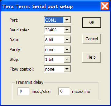
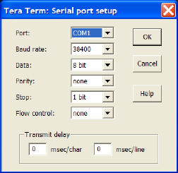
2. Open a terminal program (e.g. TeraTerm) and set the serial port on your
computer to:
▪ Baud: 38,400 baud
▪ Data Bits: 8
▪ Parity: None
▪ Stop Bits: 1
▪ Flow control: None
To do this in Tera Term, choose Setup: Serial Port and adjust the settings
appropriately for the port on your computer.
Note: the Port setting in the image below may be different, depending upon your
computer.
Figure 27 - Tera Term Serial Port Setup
5.5 Login to the Awarepoint Appliance
Press return a few times and you should see the login prompt. Enter:
▪ Username: root
▪ Password: (to be provided by Awarepoint)

Step #3 – Installing the Appliance 24
Installation Guide v2.3 – 5/10
Confidential and Proprietary ©2010, Awarepoint Corporation
5.6 Initial Set-up
Run “awp-network-config.sh” to run the configuration utility. The script displays
the main menu.:
hostname: aps.awarepoint.com
1) configure hostname
2) configure eth0
3) configure dns
4) test network
q) quit
5.7 Configure IP Address
Select option 2, “configure eth0”
eth0 is enabled
using dhcp
eth0 Link encap:Ethernet HWaddr 00:0C:29:18:FB:48
inet addr:192.168.1.175 Bcast:192.168.1.255 Mask:255.255.255.0
inet6 addr: fe80::20c:29ff:fe18:fb48/64 Scope:Link
UP BROADCAST RUNNING MULTICAST MTU:1500 Metric:1
RX packets:2746 errors:0 dropped:0 overruns:0 frame:0
TX packets:154 errors:0 dropped:0 overruns:0 carrier:0
collisions:0 txqueuelen:1000
RX bytes:291745 (284.9 KiB) TX bytes:16965 (16.5 KiB)
Interrupt:177 Base address:0x1400
1) Use DHCP
2) Manually configure
3) Restart interface
4) Enable Device
5) Disable Device
q) quit
▪ If DHCP select option 1, “Use DHCP”
▪ If Static, select option 2, “Manually Configure,” and enter the Awarepoint
Appliance’s IP address information.
(Note: examples shown below)
IP Address: 192.168.1.173
Netmask: 255.255.255.0
Gateway (default route): 192.168.1.1
Press “q” to return to the main menu.
When asked to restart the network, choose yes (y).
changes were made restart network [y/n]?

Step #3 – Installing the Appliance 25
Installation Guide v2.3 – 5/10
Confidential and Proprietary ©2010, Awarepoint Corporation
5.8 Configure the DNS
1. From the main menu, select option 3 “configure dns”
2. Change the “local domain name.”
3. Change the “nameservers.”
4. Don’t change the “domain search order”
5. Don’t change the hostname
local domain name:
-------------
nameserver list:
10.0.1.5
-------------
domain search order:
awarepoint.com
-------------
1) change domain name
2) change nameservers
3) change domain search order
q) quit
6. Enter Information
7. Press “q” to return to the main menu
5.9 Test Configuration
Choose option 4, “test network,” to test the network settings.
This will attempt to connect to https://aps.awarepoint.com. If the test is successful then
there will be no output.
Step #4 – Installing the Bridge 26
Installation Guide v2.3 – 5/10
Confidential and Proprietary ©2010, Awarepoint Corporation
6 Step #4 – Installing the Bridge
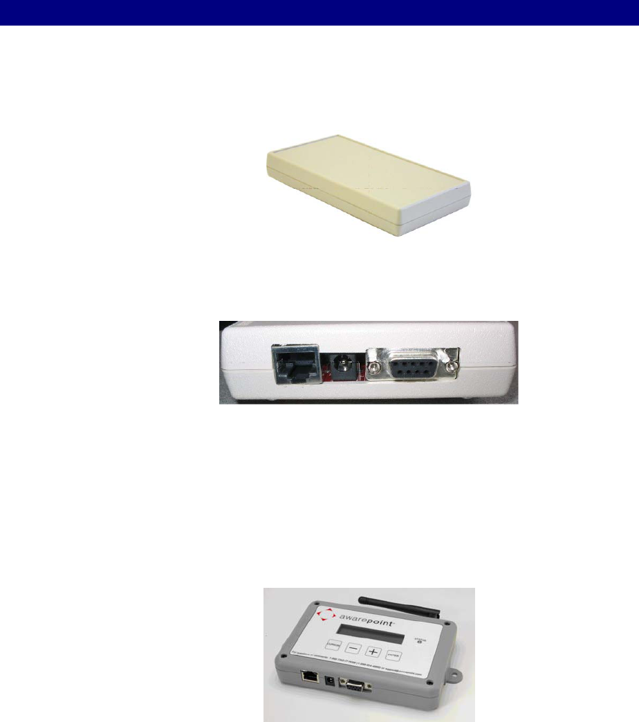
6.1 Awarepoint Bridge
There are two models of Bridges. The Bridge model B1 is shown.
Figure 28 - Awarepoint Bridge B1
The B1 Bridge has the following connectors as shown below:
Figure 29 - Awarepoint B1 Bridge Connectors
The connectors are (left to right) Network Interface, Power Connector, and Serial Port.
The Network Interface connects the Bridge to the Ethernet network, according to IEEE
standard 802.3. The power connector connects to the Awarepoint power adapter. The
Serial Port is used for configuring the Bridge. The serial interface operates on 38,400
baud with 8 data bytes, 1 stop bit, and no parity.
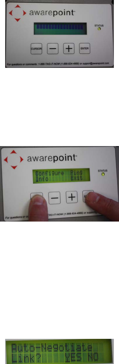
The B2 Bridge is shown below.
Note: Do not configure the B2 Bridge using the serial cable connection. If a serial
cable is connected to a Bridge, it will place the Bridge into a stalled state and will need
to be sent back to Awarepoint via RMA.
The B2 Bridge is configured by using the LCD interface on the top of the Bridge. Under
the LCD are four buttons:
Step #4 – Installing the Bridge 27
Installation Guide v2.3 – 5/10
Confidential and Proprietary ©2010, Awarepoint Corporation
Figure 30 - B2 Bridge
▪ Cursor
▪ Down Arrow
▪ Up Arrow
▪ Enter
The Bridge menu can be entered at any time by holding down the Cursor and Enter
buttons simultaneously.
Figure 31 - Entering the Bridge Menu
These are the menu options:
▪ Configuration
▪ Info
▪ Ping
▪ Exit
Choose one of the menu options by pressing the Cursor button until it is under the
menu option. Press the Enter button to get into the selected menu.
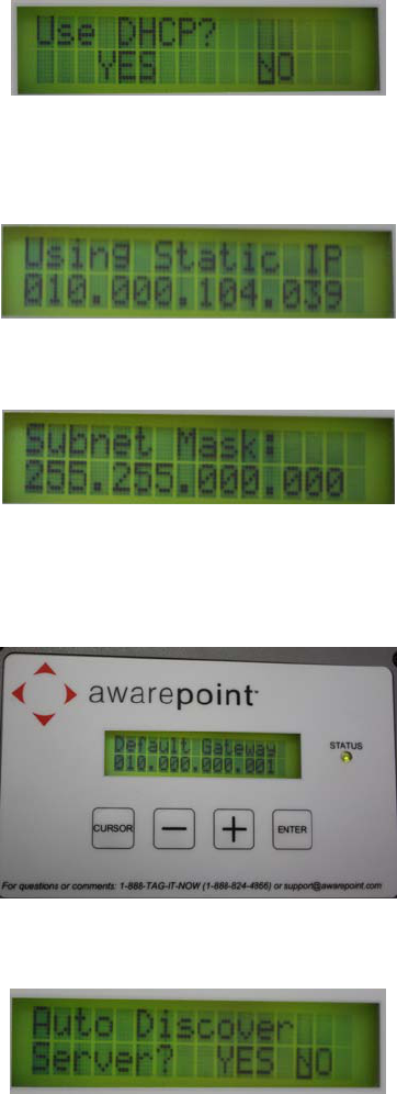
Configuration allows the user to configure the below options.
▪ Auto-Negotiation Link – Yes/No
Figure 32 - Auto-Negotiation Link
Step #4 – Installing the Bridge 28
Installation Guide v2.3 – 5/10
Confidential and Proprietary ©2010, Awarepoint Corporation
If No:
– Link Speed – 10/100
– Duplex Mode – Half/Full
▪ DHCP – Yes/No
Figure 33 - DHCP option
If No:
– IP Address
Figure 34 - Static IP Address
– Subnet Mask
Figure 35 - Subnet Mask
– Default Gateway
Figure 36 - Default Gateway
▪ Auto Discover Server – Yes/No
Figure 37 - Auto Discover Server
Step #4 – Installing the Bridge 29
Installation Guide v2.3 – 5/10
Confidential and Proprietary ©2010, Awarepoint Corporation
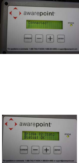
Figure 38 - Bridge Connected to the Appliance
If No:
– Server IP Address
▪ Save Settings – Yes/No
Info allows the user to view the following information about the Bridge.
Figure 39 - Bridge Information
▪ Ethernet MAC
▪ Auto-Negotiate Link
▪ Link Speed
▪ Duplex Mode
▪ Use DHCP?
▪ IP Address
▪ Subnet Mask
▪ Default Gateway
▪ Server IP Address
▪ Channel
Use the up arrow and down arrow buttons to increment a number higher or lower to
achieve the correct number for an IP address, subnet mask, or default gateway. By
holding down the Up Arrow or Down Arrow buttons, the user can increment a number
by tens.
Step #4 – Installing the Bridge 30
Installation Guide v2.3 – 5/10
Confidential and Proprietary ©2010, Awarepoint Corporation
6.2 Physical Installation
Find a suitable location for the Bridge. Mounting in switch closets is preferred, as the
Bridge is less likely to be disturbed. You will need one power outlet and one Ethernet
port.
Prior to installing the Bridge, read its wireless MAC address from the bottom. Indicate
on a paper copy of the map where this Bridge is located along with its MAC address. It
is also advised to communicate the wired MAC address to the deployment site’s IT
department.
Attach double-sided tape to each corner on the bottom of the Bridge and press the
Bridge against the surface to affix it. Make sure to “tidy-up” the network and power
cords with wire anchors and zip ties as needed.
6.3 Connect to the Serial Interface - B1 Model Only
Connect a serial cable between the Bridge and the computer you will use to configure
the Bridge (normally your laptop computer).
Open a terminal program (e.g. TeraTerm) and set the serial port on your computer to:
▪ Baud: 38,400 baud
▪ Data Bits: 8
▪ Parity: None
▪ Stop Bits: 1
▪ Flow control: None
To do this in Tera Term, choose Setup: Serial Port and adjust the settings appropriately
for the port on your computer.
Note – the Port setting in the image below may be different, depending upon your
computer.
Figure 40 - Tera Term Serial Port Setup
Step #4 – Installing the Bridge 31
Installation Guide v2.3 – 5/10
Confidential and Proprietary ©2010, Awarepoint Corporation
6.3.1 Configure Network Interface – B1 Model Only
1. Plug the Bridge into the power outlet.
2. Open TeraTermpro and press the Enter button three times. This will initiate the
program.
3. On the terminal program you should see boot information. When prompted,
press ‘c’ to configure the IP Address settings. At the prompt, enter return to
accept the existing MAC address.
4. At the next prompt, if using DHCP to set the IP address of the Bridge then press
Y. Otherwise (if you are setting the IP address with a static IP address) press N,
and enter the IP Address, subnet mask, and default gateway for this Bridge.
5. Enter the IP Address of the Appliance.
The Bridge will proceed to ping the Appliance, test communications with the Appliance,
and perform an internal test. If the communications tests fail, change the IP address
settings and retry.
After verifying network configuration settings, if the Bridge still fails, you may need to
use the Network Analyzer to determine the problem with the port.
If the internal test (“Zigbee Board test”) fails, replace the Bridge.
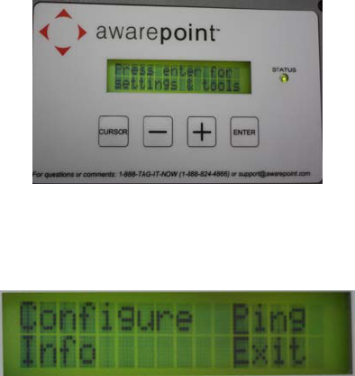
6.4 Configure Network Interface – B2 Model Only
1. Plug the Bridge into the Ethernet cable and power outlet.
2. As the Bridge boots, watch for the “Press enter for tools and setting” message
on the LCD screen. Press the Enter button once to enter the menu.
Figure 41 - B2 Enter for Settings & Tools
3. Press the Cursor button until it is under the Configuration menu. Press the
Enter button to go into the configuration menu.
Figure 42 - B2 Menu
Step #4 – Installing the Bridge 32
Installation Guide v2.3 – 5/10
Confidential and Proprietary ©2010, Awarepoint Corporation
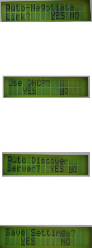
4. Follow the steps through the configuration menu to configure the Bridge.
Answer the question of “Auto-Negotiate Link?” by using the Cursor button to
place the screen cursor under “YES” or “NO.” Press the Enter button to choose
the selection and advance to the next screen.
Figure 43 - Auto-Negotiation Link
5. If the answer is “NO,” follow the questions to answer “Link Speed” and “Duplex
Mode.”
6. Answer the “Use DHCP?” question the same way as the last question. After the
selection is made, press the Enter button to take the selection and advance to
the next screen.
Figure 44 - DHCP option
7. If the answer is “NO,” follow the questions to fill in the IP address, subnet mask
and default gateway.
8. Answer the “Auto Discover Server” question in the same manner as the above
questions. Press the Enter button to take the selection and advance to the
screen.
Figure 45 - Auto Discover Server
9. If the answer is “NO,” enter the IP address of the server on the next screen
prompt.
10. Answer the “Save Settings” question. After pressing the Enter button, the
Bridge will boot with the new settings.
Figure 46 - Save Settings for B2 Bridge
11. If the answer is “NO,” the save will be cancelled and the Bridge will boot with
the existing settings.
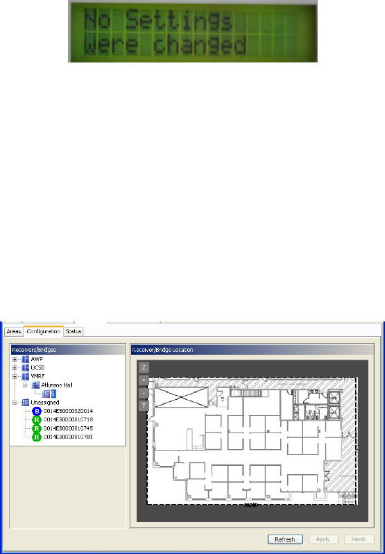
Step #4 – Installing the Bridge 33
Installation Guide v2.3 – 5/10
Confidential and Proprietary ©2010, Awarepoint Corporation
Figure 47 - No Settings Were Changed
12. Once the Bridge has booted, the user can enter the Bridge Menu any time by
pressing the Cursor and Enter buttons at the same time once or twice.
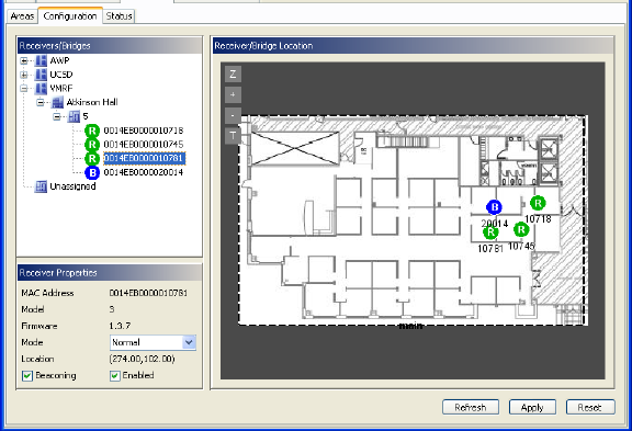
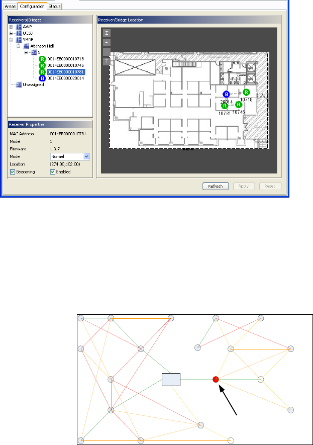
6.5 Place Awarepoint Bridge on Map
Open the System Manager and choose the Positioning: Configuration tab. Expand the
Sensors/Bridges tree and select the floor where the Bridge is located.
Expand the unassigned section of the Sensors/Bridges tree.
The Bridge you just installed should show up in the Unassigned section of the device
tree. If it is functioning correctly, the icon for the Bridge should be blue.
Figure 48 – Bridge Icons
Drag the Bridge icon onto the map and place it where it is located.
Step #4 – Installing the Bridge 34
Installation Guide v2.3 – 5/10
Confidential and Proprietary ©2010, Awarepoint Corporation
Figure 49 - Placing Awarepoint Bridge
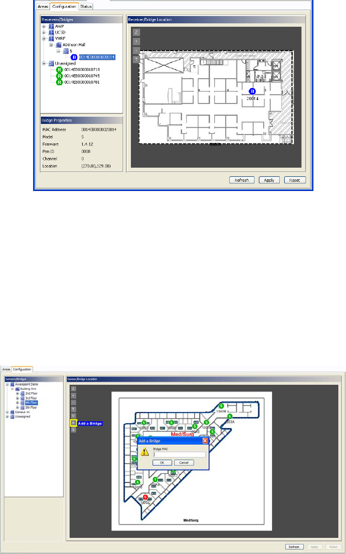
Bridges can also be placed using the B button on the left side of the map. This method
of placing Bridges on the map is helpful if the list of unassigned Bridges is very long.
Choose the B button and then type in the last 5 digits of the Bridge’s MAC address.
Choose OK. The Bridge will appear in the center of the map. It can then be moved to
the appropriate location.
Note: Use caution to only reposition the added Bridge, and not a Bridge that has
already been placed on the map.
Figure 50 - Placing Awarepoint Bridge Using B Button
Choose the Apply button to save the changes.
Step #4 – Installing the Bridge 35
Installation Guide v2.3 – 5/10
Confidential and Proprietary ©2010, Awarepoint Corporation
6.5.1 Adding a Bridge Location Comment
Once a Bridge is on the map, double click the icon of the Bridge to add a comment on
the location. The more descriptive the comment (i.e. “2nd Floor – room 232, front wall,
under desk”), the easier it will be for a technician to find the Bridge at a later date.

Step #5 – Installing the Sensors 36
Installation Guide v2.3 – 5/10
Confidential and Proprietary ©2010, Awarepoint Corporation
7 Step #5 – Installing the Sensors
Sensors need to be located throughout the coverage area, including along the
perimeter. When installing Sensors, begin by installing Sensors near the Bridge and
work progressively outward in concentric circles. This will optimize network topology.
The preferred sequence of installation is to have the Appliance and Bridges installed
and configured properly before installing Sensors.
For some installations, the Sensors are added to the system before the site visit.
Before adding Sensors, you should check to see if they are already in the system.
7.1 Awarepoint Sensors
There are several models of Sensors.
Figure 51 - R1 Sensor
Figure 52 - S2 Sensor
Figure 53 - S2U Sensor
The R1 Sensor displays its status with three visual indicators in the form of Light
Emitting Diodes (LEDs).
The topmost LED indicates network status. Red indicates that the Sensor cannot
communicate with any other devices. Yellow indicates that it can communicate with the
Bridge but not the Appliance. Green means that it can communicate with the Bridge
and Appliance.
The middle LED indicates network activity. In normal operation, it will occasionally
blink.
The bottom LED (blue) indicates power. If the device is plugged into an outlet that has
power then it is illuminated.
The S2, S2C and S2U Sensor displays its network status with one visual indicator in
the form of a Light Emitting Diode (LED). If it is off, then the device is defective or not
powered. Red indicates that the Sensor cannot communicate with any other devices.
Yellow indicates that it can communicate with the Bridge but not the Appliance. Green
means that it can communicate with the Bridge and Appliance.

Step #5 – Installing the Sensors 37
Installation Guide v2.3 – 5/10
Confidential and Proprietary ©2010, Awarepoint Corporation
7.2 Physical Installation
The Sensors are installed in standard electrical power receptacles. Prior to installing
the Sensor you must locate a powered outlet. Verify that the receptacle has power by
using an electrical tester. For S2C and S2U Sensors, use the appropriate approved
power cord matching the receptacle.
7.3 Secure Awarepoint Sensors
Unless otherwise directed by Project Manager, the preferred method of securing
Sensors to outlets is to use 3M VHB double sided tape to affix Sensors to electrical
outlet. Apply double-sided tape strip to the top of the output faceplate and install the
Sensor, being sure to achieve sufficient contact between the tape and the Sensor.
Apply pressure for 10-15 seconds to maximize adhesive strength. (Note: There are
other methods of securing Sensors. These methods would have to be pre-approved by
Awarepoint VP of Professional Services)
CAUTION: To remove a Sensor that has been secured in place, slide a plastic putty knife between
Sensor and faceplate. Be sure to avoid contact with the electrical prongs with anything
except the plastic putty knife. If this method of Sensor removal will not work, another
method is to use an insulated blade screwdriver to first remove the electrical faceplate
and Sensor from the wall, then separate the Sensor from the faceplate. NEVER reach
behind the Sensor in an effort to insert or remove it from the outlet as electrical shock
may occur if you contact the electrical prongs while they are still inserted in the outlet.
For insertion or removal, grasp the Sensor by the sides only.
7.4 Verify the Sensor Connects to the Network
Once you plug the Sensor into an outlet, it will attempt to connect to the Awarepoint
network. This process will take approximately one minute. When the Sensor has
completed this process, the Network LED will be illuminated Green. If the Sensor is
unable to connect to the network (out of range of a network or network not properly
configured), the Sensor will continue to attempt to connect to the network and the
Network LED will be Red.
If a Sensor keeps cycling through different colors, that Sensor needs to be replaced.
Note: If the Sensor is not running the most current firmware, it may not be able to
successfully connect to the network until the firmware is updated.
Once the Sensor has successfully connected to the network, mark the Sensor location
and its MAC address on a paper copy of the map.
Step #5 – Installing the Sensors 38
Installation Guide v2.3 – 5/10
Confidential and Proprietary ©2010, Awarepoint Corporation
7.5 Place Awarepoint Sensor on Map
Open the System Manager and choose the Positioning: Configuration tab. The Sensor
you just installed should show up in the Unassigned section of the device tree. If it is
functioning correctly, the icon for the Sensor should be green.
In the device tree, expand the Campus and Building so that you can see the floor. Click
on the floor to display the map for the floor. Drag the Sensor icon onto the map and
place it where it is located.
Figure 54 - Placing Awarepoint Sensors
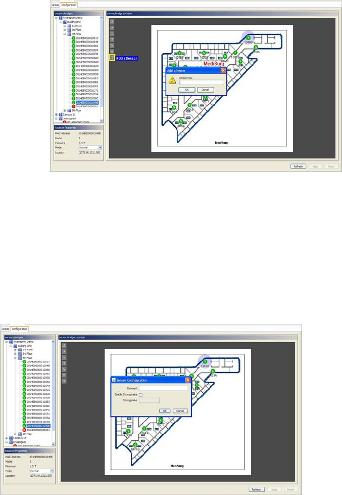
Sensors can also be placed using the S button on the left side of the map. This
method of placing Sensors on the map is helpful if the list of unassigned Sensors is
very long.
1. Choose the S button and then type in the last 5 digits of the Sensor’s MAC
address.
2. Choose OK.
The Sensor will appear in the center of the map. It can then be moved to the
appropriate location.
Note: Use caution to make sure that you are repositioning the added Sensor, not
moving a Sensor that has already been placed on the map.
Step #5 – Installing the Sensors 39
Installation Guide v2.3 – 5/10
Confidential and Proprietary ©2010, Awarepoint Corporation
Figure 55 - Placing Awarepoint Sensors using S button
Choose the Apply button.
7.5.1 Adding a Comment to Sensor Location
Once Sensor is on the map, double click the icon of the Sensor to add a comment on
the location. The more descriptive the comment (i.e. “3rd Floor - PACU Nurse Station,
back wall, under cabinets”), the easier it will be for a technician to find the Sensor at a
later date.
Figure 56 - Adding Comments to Sensors
Continue to place all Sensors. As they are placed, they will join the network. Some
routing lines will be displayed as shown below.
Step #5 – Installing the Sensors 40
Installation Guide v2.3 – 5/10
Confidential and Proprietary ©2010, Awarepoint Corporation
Figure 57 - Placing All Awarepoint Sensors
7.6 Optimize Awarepoint Sensor Locations
Once you have placed several Sensors in an area, you need to optimize the mesh
network. In a good mesh network, all Sensors have redundant paths back to the Bridge
so that if one Sensor is removed or disabled, the other Sensors will be able to route
around it. See below for a visual description:
Bridge
A
Bowtie Network
At this Node
Figure 58- Bowtie Network
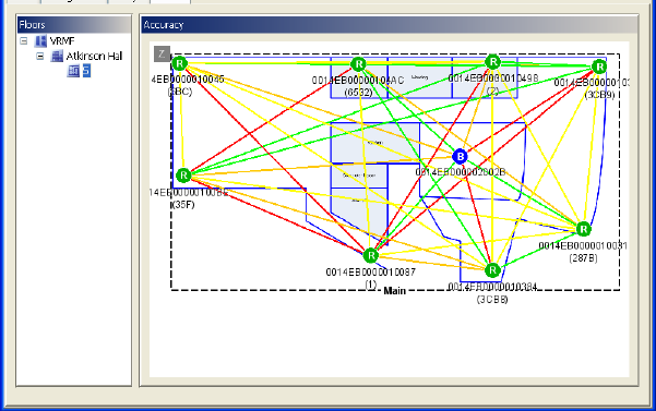
To check the mesh network, Open the System Manager, choose the Positioning:
Status tab, and select the floor where you installed the Sensors. You will see an image
similar to the following.
These Sensor colors mean:
▪ Red – Down
▪ Yellow - Connected as a reduced functional device (RFD). This means that
either the Sensor is a 5-hop Sensor and can't have any children or it is trying to
become a full functional device (FFD).
▪ Dark Green - A FFD connected to the Bridge the Appliance thinks it should be
connected to.
Step #5 – Installing the Sensors 41
Installation Guide v2.3 – 5/10
Confidential and Proprietary ©2010, Awarepoint Corporation
▪ Light Green - A FFD connected to any Bridge except the Bridge the Appliance
thinks it should be connected to. An examination of the network should reveal
why the particular Sensor(s) are attached to an "incorrect" Bridge.
Figure 59 – Sensors and Signal Strength
The lines between Sensors indicate the signal strength between them.
▪ Green - A strong (-60 or stronger) connection. You should see very few of these
in any standard install.
▪ Yellow - A moderate (-75 to -61) connection. Many parent-child connections
should be yellow, but few others should
▪ Orange - A weak (-82 to -76) connection. There should be many of these
connections between non-connected sensors.
Note: You must be connected to the System Manager through the Local Network to
view this page. This page cannot be viewed when accessing System Manager through
the Network Operations Center.
Add/move Sensors until each Sensor has multiple paths back to the Bridge. The
example above shows a good mesh layout.
7.7 Deleting Unused Bridges and Sensors from System
1. Open the System Manager and login.
2. Click on the Device Management Tab.
3. Click on the Devices sub-tab.
4. Select either Bridges or Sensors.
5. To delete, highlight the appropriate MAC address and choose Delete at the
bottom of the screen. Multiple MAC addresses can be selected simultaneously
by holding the “Ctrl” key while clicking.
Use caution when purging from the system.

Step #6 – Installing the Tags 42
Installation Guide v2.3 – 5/10
Confidential and Proprietary ©2010, Awarepoint Corporation
8 Step #6 – Installing the Tags
Tags are attached to equipment to be tracked.
Prior to installing Tags, you should have an equipment list describing what the
customer wants Tagged, with approximate quantities for each. Equipment to be
Tagged should stay in the coverage area or it will not be found.
Prior to installing Tags, the Sensors, Appliance, and Bridges must be correctly
installed.
For some installations, the Tags are added to the system before the site visit. Before
adding Tags, you should check to see if they are already in the system.
T1 Tags are being phased out. They should be replaced with T2 Tags when possible.
8.1 Awarepoint Tags
There are several models of Tags.
Figure 60 - T1 Tag
Figure 61 - T2-A Tag
The top of the Tag is a movable slider that is used to send a signal to the Awarepoint
Appliance. When the slider is changed, the Tag will transmit a message to the
Appliance indicating the new status of the slider (red or green). This is NOT an on/off
switch – the Tag is always “on.” When the slider is changed, the new status is
displayed on the Light Emitting Diode (LED) on the T1 only.
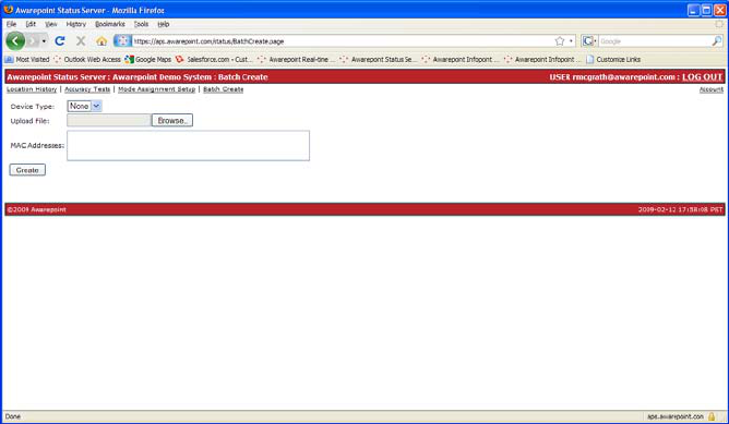
8.2 Batch Create Tags
1. Open a web browser and navigate to http://aps.awarepoint.com/status.
2. Enter your login and password information.
3. Choose the link for the appropriate facility location.
4. At the top of the screen, choose the link “Batch Create.”
5. Select the device type
Step #6 – Installing the Tags 43
Installation Guide v2.3 – 5/10
Confidential and Proprietary ©2010, Awarepoint Corporation
6. Either upload a .csv file with a listing of the MAC addresses of the appropriate
devices, or type the MAC addresses into the ‘MAC Addresses’ field.
7. Choose ‘Create.’
Figure 62 - Batch Create Tags in Status Server
8.3 Physical Installation
Tags are attached to assets using a variety of methods, including double-sided tape or
zip-tie.
Note: After tightening zip-ties, cut off the excess portion flush with locking connection
to avoid leaving sharp edges.
These are the general guidelines when installing Tags.
▪ Don’t mount asset Tags underneath or inside an asset.
▪ Place at approximately three feet above ground level when possible.
▪ Avoid mounting Tag directly to metallic surfaces when possible.
▪ Attach the Tag in a manner that the MAC address is visible.
▪ Avoid flat placement (e.g. green/red strip facing up toward the ceiling or down
toward the floor)
Step #6 – Installing the Tags 44
Installation Guide v2.3 – 5/10
Confidential and Proprietary ©2010, Awarepoint Corporation
Figure 63 - Tag Zip Tie Attachment
Figure 64 - Tag Double-Sided Tape Attachment
Write down the MAC address and asset information, including:
▪ Type of Asset (Wheelchair, IV Pump, Gurney, etc.)
▪ Nickname, if any (for example, Gurney #1)
▪ Department that it belongs to, if any
▪ Manufacturer
▪ Model
▪ Serial Number
▪ Asset Control Number
▪ Unique Identifier – for most installations this is the facility’s asset ID number
Step #6 – Installing the Tags 45
Installation Guide v2.3 – 5/10
Confidential and Proprietary ©2010, Awarepoint Corporation
8.4 Temperature Tag
1. Log into the System Manager and choose the Device Management tab.
2. Click the Create Mode button.
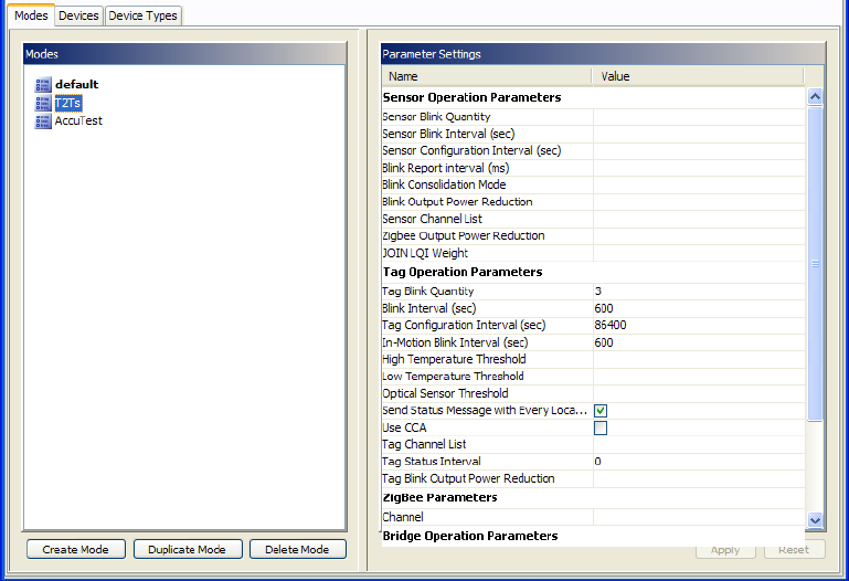
3. Enter the mode settings shown below:
▪ Tag Blink Quantity: 3
▪ Blink Interval (sec): 600
▪ Tag Configuration Interval (sec): 86400
▪ In-Motion Blink Interval (sec): 600
▪ Check the box next to “Send Status Message with Every Location Update”
4. Click “Apply”
Figure 65 - Creating Temperature Tag Mode
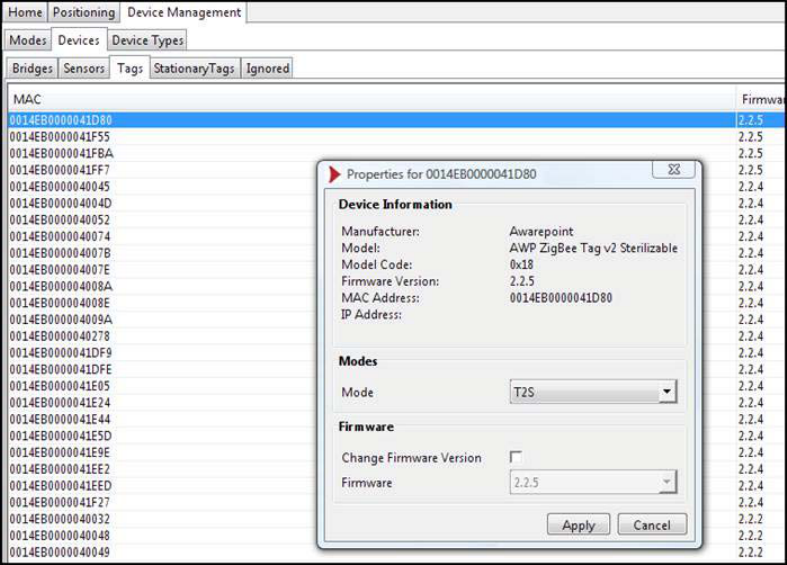
As soon as the Tags physically arrive in a coverage area and show up in the system,
they should be assigned to the mode through the System Manager in the Device
Management tab. (See Figure Below)
Step #6 – Installing the Tags 46
Installation Guide v2.3 – 5/10
Confidential and Proprietary ©2010, Awarepoint Corporation
Figure 66 - Assigning Tags to a Mode
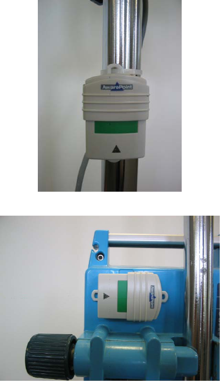
8.4.1 Physical Installation of Temperature Tags (T2T)
Temperature Tags (T2T) should be installed on the outside of the asset that to be
monitored, on the side that is closest to a Sensor. The cord should be supported on
the outside of the asset to be monitored using the “tape on” cable tie down squares. A
two inch service loop should be added near the Tag so that you absolutely remove all
tension from the cord (See photo).
Using another “tape on” cable tie down square, affix the bottom part of the Sensor cord
(where it meets the black rubber Sensor) to the side wall of the asset that will be
monitored. Be sure that the Sensor end of the Tag is toward the back of the asset,
away from the door to decrease temperature fluctuation.
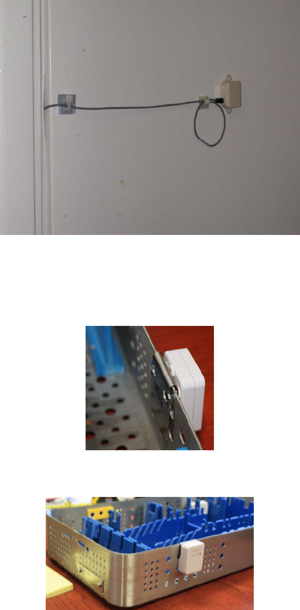
Step #6 – Installing the Tags 47
Installation Guide v2.3 – 5/10
Confidential and Proprietary ©2010, Awarepoint Corporation
Figure 67 - Temperature Tag Installation with Service Loop
8.5 Sterilizable Tag
These Tags should always be installed on the outer container, as they cannot survive
ultrasonic processing.
Figure 68 - Autoclave Tag
Figure 69 - Autoclave Tag on Outside of Tray
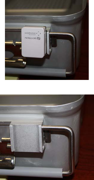
Step #6 – Installing the Tags 48
Installation Guide v2.3 – 5/10
Confidential and Proprietary ©2010, Awarepoint Corporation
They can be attached inside the tray, as long as they are removed before sterilization.
Figure 70 - Autoclave Tag in Bracket
Figure 71 - Autoclave Tag Removed from Bracket
1. Log into the System Manager and choose the Device Management tab.
2. Choose the Create Mode button.
3. Enter the mode settings shown below:
▪ Tag Blink Quantity: 3
▪ Blink Interval (sec): 600
▪ Tag Configuration Interval (sec): 86400
▪ In-Motion Blink Interval (sec): 15
▪ Check the box next to “Send Status Message with Every Location Update”
▪ Tag Status Interval: 600
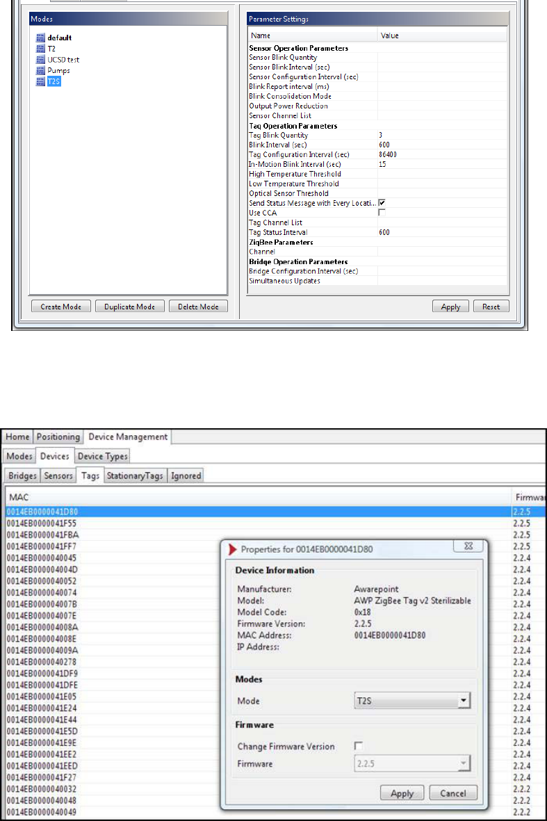
Step #6 – Installing the Tags 49
Installation Guide v2.3 – 5/10
Confidential and Proprietary ©2010, Awarepoint Corporation
Figure 72 - Creating Sterilizable Tag Mode
As soon as the Tags physically arrive in a coverage area and show up in the system,
they should be assigned to the mode through the System Manager in the Device
Management tab. (See Figure Below)
Figure 73 - Assigning Tags to a Mode
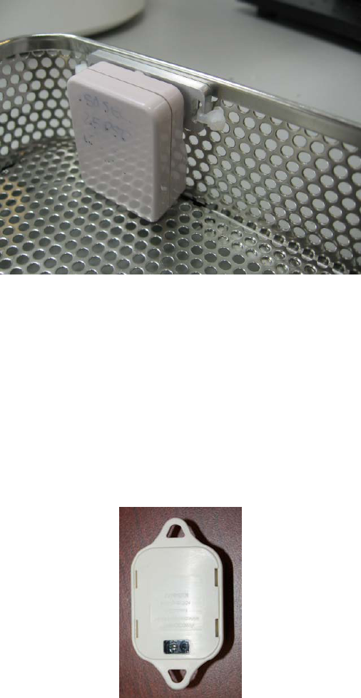
Step #6 – Installing the Tags 50
Installation Guide v2.3 – 5/10
Confidential and Proprietary ©2010, Awarepoint Corporation
8.5.1 Physical Installation of Sterilizable Tags (T2S)
Please provide Awarepoint with the model of the tray-container for the appropriate clip
and instructions.
Figure 74 - Sterilizable Tag Installation
The torque setting used for the T2S mounting plate is 12 in-lbs (max).
Note: Do not over tighten. If these screws are over tightened, it can crack the case
and the cleaning fluid will enter the case.
8.6 Optical Sensor Tag
These Tags are meant to alert you when they have been removed.
A piece of aluminum tape should be mounted directly under the optical sensor window
on the Tag on the asset. The tape should be cut large enough to cover the area of the
Optical Sensor, but small enough so that it doesn’t extend beyond the Tag (should be
about ½” square).
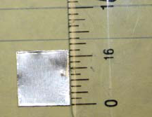
Step #6 – Installing the Tags 51
Installation Guide v2.3 – 5/10
Confidential and Proprietary ©2010, Awarepoint Corporation
Set the threshold at 100 (which should be the default).
Place the optical Tag on the asset with the optical Sensor facing outside.
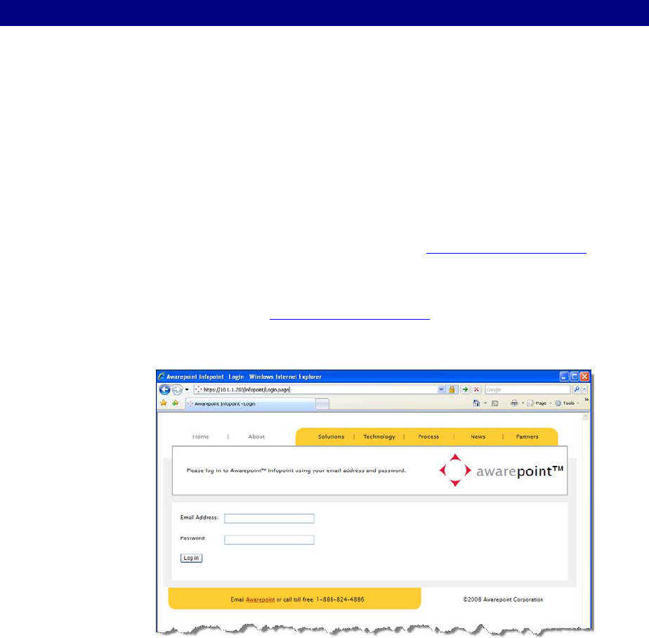
Step #7 – Associating the Tags with Assets 52
Installation Guide v2.3 – 5/10
Confidential and Proprietary ©2010, Awarepoint Corporation
9 Step #7 – Associating the Tags with Assets
After Tags have been physically attached to the assets that will be tracked, Tags and
assets need to be electronically connected in the Awarepoint system. This can be
done in Infopoint or System Manager.
The following section describes how to make this Tag/asset association in Infopoint.
9.1 Accessing Infopoint
Before you can access Infopoint, Awarepoint needs to set up an account with your
email address and initial password.
You can contact Awarepoint by sending an email to support@awarepoint.com.
1. From your web browser, type this URL into your web browser:
http://aps.awarepoint.com
2. You will be prompted to enter your email address and password.
Figure 75 - Infopoint Login
Your view will depend on the permissions set when your account was set up by
Awarepoint. You may not have access to all the tabs you see here.
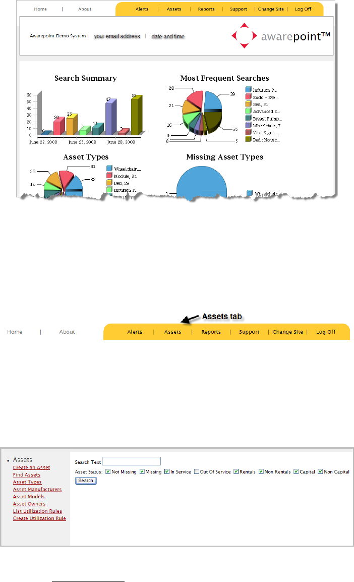
Step #7 – Associating the Tags with Assets 53
Installation Guide v2.3 – 5/10
Confidential and Proprietary ©2010, Awarepoint Corporation
Figure 76 - Infopoint Main Page
9.2 Adding Assets
In the Infopoint interface, choose the Assets tab.
Figure 77 - Assets Tab
When new assets are purchased or rented, they need to be added to the system.
Changes in assets, asset types, manufacturers, models or owners, also need to be
edited in the system.
Figure 78 - Manage Assets
1. Choose Create an Asset from the left column.
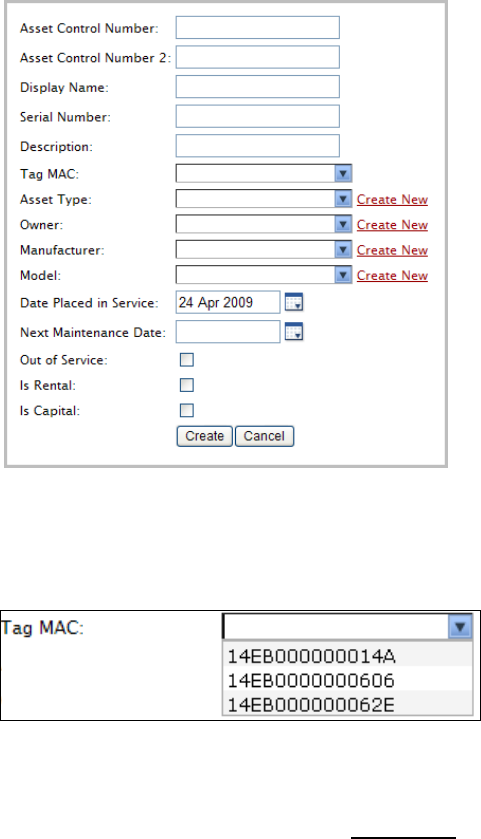
Step #7 – Associating the Tags with Assets 54
Installation Guide v2.3 – 5/10
Confidential and Proprietary ©2010, Awarepoint Corporation
Figure 79 - Asset Information
2. Enter the asset information.
3. Choose the Tag MAC from the drop-down list.
Figure 80 - Tag MAC drop-down list
4. Choose Create.
5. If you need to add new asset attributes, chose the Create New
▪ Asset Type
link in the right
column, next to the asset attribute that you would like to create.
▪ Owner
▪ Manufacturer
▪ Model
9.3 Edit Assets
1. Locate the asset, either by
▪ Searching for the asset by search text or
▪ Browsing through asset attributes (asset type, owner, manufacturer or
model), and listing assets
2. Choose the Edit button to the asset you would like to edit.
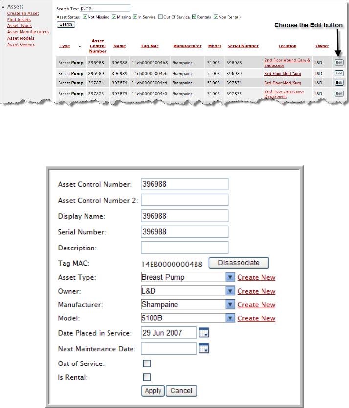
Step #7 – Associating the Tags with Assets 55
Installation Guide v2.3 – 5/10
Confidential and Proprietary ©2010, Awarepoint Corporation
3. Make changes to the asset information, then choose Apply.
9.4 Delete Assets
Before deleting an asset, you must first take it out of service. When you take an asset
out of service, it preserves the history but removes it from the Searchpoint search. It
retires the asset but it can be returned to service at a later time. One example of taking
an asset out of service would be when a rental asset is returned.
1. Find the asset you would like to delete.
For example, to delete the Isolux Headlight, search for Headlights and then
choose the Edit button.
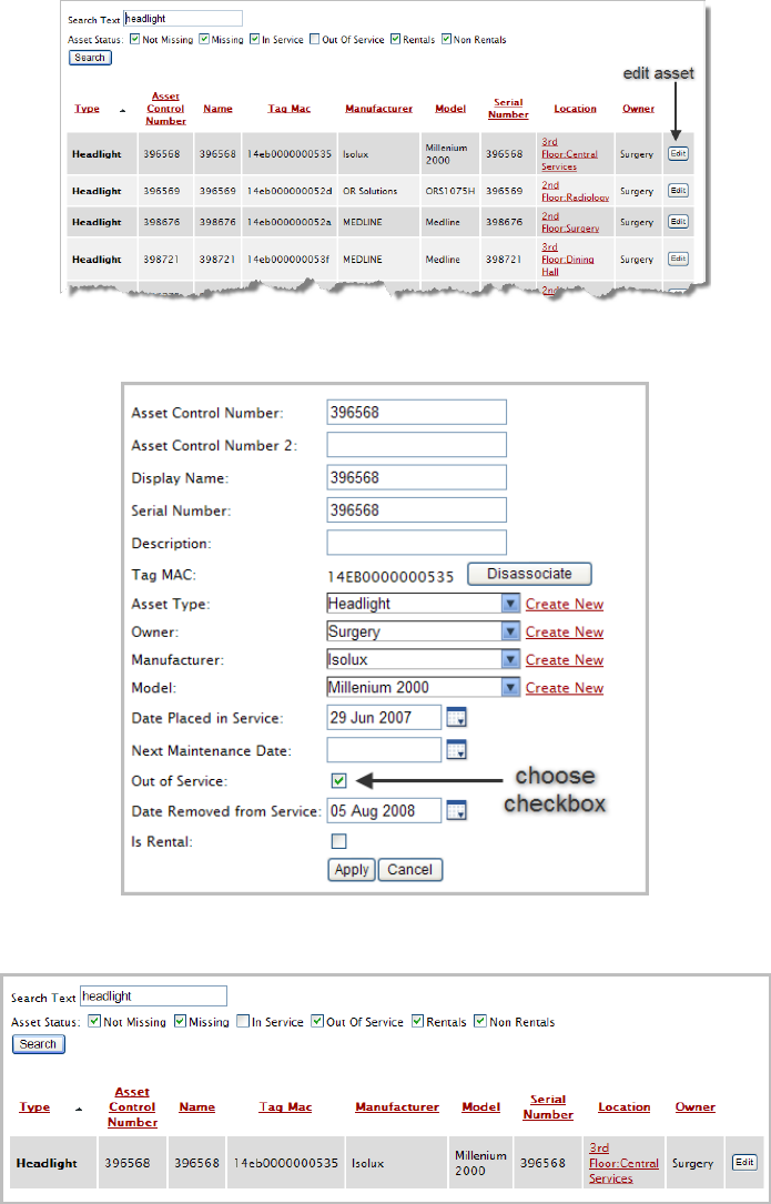
Step #7 – Associating the Tags with Assets 56
Installation Guide v2.3 – 5/10
Confidential and Proprietary ©2010, Awarepoint Corporation
2. Change the asset attribute to “out of service,” then the Apply button.
3. Find the asset again by using the “out of service” attribute.
4. Choose the Edit button for the asset. The Delete button is now available.
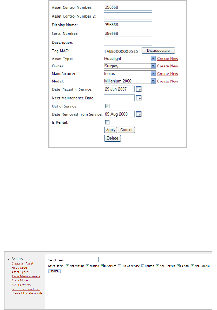
Step #7 – Associating the Tags with Assets 57
Installation Guide v2.3 – 5/10
Confidential and Proprietary ©2010, Awarepoint Corporation
5. Choose the Delete button to delete the asset.
9.5 View or edit asset types, manufacturers, models and owners
From the column in the left, choose Asset Types, Asset Manufacturers, Asset Models
or Asset Owners.
Figure 81 - Manage Assets
A list of the attribute will be displayed.
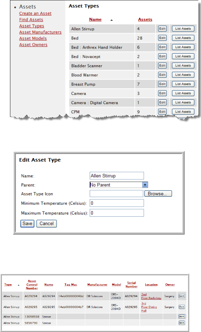
Step #7 – Associating the Tags with Assets 58
Installation Guide v2.3 – 5/10
Confidential and Proprietary ©2010, Awarepoint Corporation
You can
Edit the attribute
When you are finished editing the attribute, choose Save.
List the assets associated with that attribute
9.5.1 Configure the temperature range for an asset type
Configure the minimum and maximum temperature range for an asset through the Edit
Asset Type page.
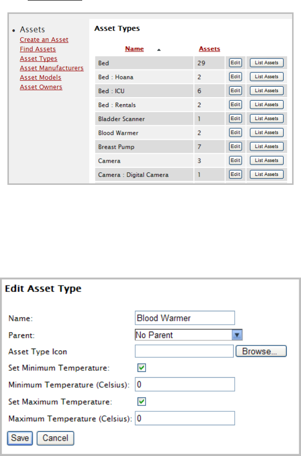
Step #7 – Associating the Tags with Assets 59
Installation Guide v2.3 – 5/10
Confidential and Proprietary ©2010, Awarepoint Corporation
1. Choose Asset Types through the link in the left hand pane.
2. Choose the Edit button next to the asset type.
3. Choose the Set Minimum Temperature and Set Maximum Temperature
checkboxes. Then set the minimum and maximum temperatures in Celsius.

Step #8 – System Testing and Quality Control 60
Installation Guide v2.3 – 5/10
Confidential and Proprietary ©2010, Awarepoint Corporation
10 Step #8 – System Testing and Quality Control
This section describes how to test the system prior to System Acceptance.
10.1 Awarepoint Sensors
Verify that Sensors are properly secured to the faceplate.
Using the System Manager verify the following:
▪ Each Sensor has more than one path back to the Bridge.
▪ None of the Sensors that are on the map are red
▪ None of the Sensors that are unassigned are green
▪ Any unused Sensors have been deleted from the system. Use caution when
purging.
10.2 Awarepoint Bridges
Using the System Manager verify the following:
▪ For redundancy, there are at least two Bridges in each area
▪ None of the Bridges shown on the map are red
▪ None of the Bridges that are unassigned are blue
▪ Any unused Bridges have been deleted from the system. Use caution when
purging.
10.3 Awarepoint Tags
Verify that Tags are properly secured to their asset.
Using the System Manager verify the following:
▪ All Tags have manufacturer, model, asset control number, and serial number
filled in.
▪ Any Tags out of the coverage area can be explained
▪ Any unused Tags have been deleted from the system. Use caution when purging.
10.4 Accuracy Testing
1. Log into the Status Server <http://aps.awarepoint.com/status
2. Choose the site to be tested.
>.
On the home page of the site to be tested, choose the “Accuracy Tests” link on
the top left of the page. Click on the link to perform a new accuracy test.
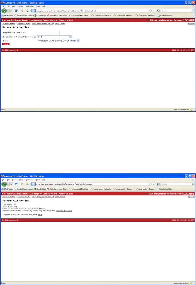
Step #8 – System Testing and Quality Control 61
Installation Guide v2.3 – 5/10
Confidential and Proprietary ©2010, Awarepoint Corporation
3. Enter the Test Point Name, select the asset type of Tags to be used for the test,
and select the building and floor where the test will be taken.
4. Choose Next. A map will come up of the selected floor.
Figure 82 - Accuracy Testing in Status Server
5. Set the Tags in any location, about waist-high on the selected floor, about a foot
apart from each other. Do not bunch the Tags. Let them sit for 15 to 20
seconds and then click their physical location on the map.
You will be able to view the test on the next page by choosing the “View Test
Results” link.
Figure 83 - Viewing Accuracy Test Results
Average error should be between 1-3 meters.
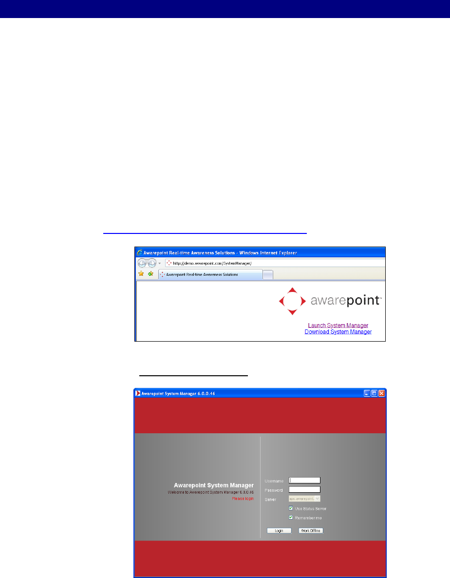
Adding Additional Assets After Installation 62
Installation Guide v2.3 – 5/10
Confidential and Proprietary ©2010, Awarepoint Corporation
11 Adding Additional Assets After Installation
After the initial installation at a customer site, additional assets at that site need to be
added to the Awarepoint system.
Assets can be added using System Manager or Infopoint.
In some cases, it may be easier to add assets while you are not connected to the site
network or even to the Internet. To begin with, you will need an Internet connection to
launch System Manager and to connect to the site through System Manager. Then
you can choose to go offline and add assets.
The following section explains how to use System Manager as an offline Asset
Manager to add assets.
11.1 System Manager
1. Open a web browser and navigate to
http://demo.awarepoint.com/SystemManager.
Figure 84 - Download System Manager
2. Choose Launch System Manager.
Figure 85 - System Manager Login
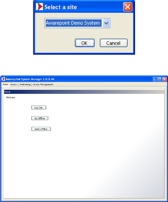
Adding Additional Assets After Installation 63
Installation Guide v2.3 – 5/10
Confidential and Proprietary ©2010, Awarepoint Corporation
3. Enter your user name and password, then choose the Login button.
4. Choose the appropriate site from the drop-down menu, then choose OK.
5. At the Home tab, you can choose the Go Offline button.
6. Choose the Assets tab.
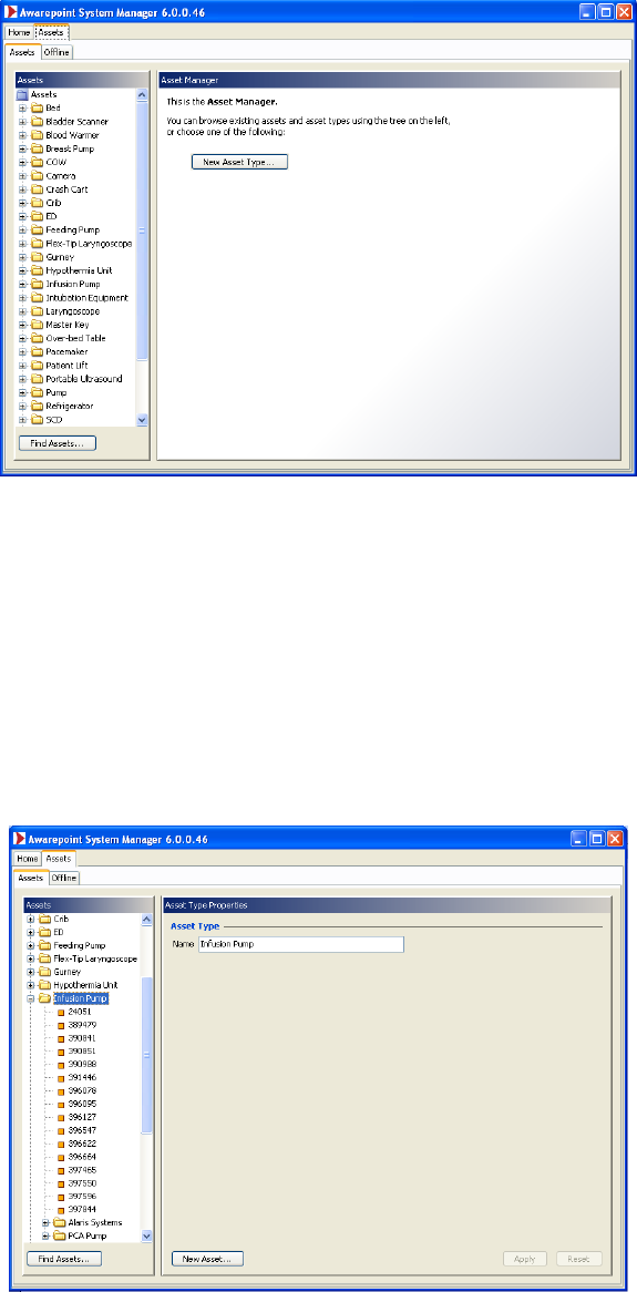
Adding Additional Assets After Installation 64
Installation Guide v2.3 – 5/10
Confidential and Proprietary ©2010, Awarepoint Corporation
Figure 86 - Asset Manager
At the offline Asset Manager, you can
▪ Add an asset to an existing asset type
▪ Add a new asset type
▪ Find an existing asset
11.2 Add an Asset to an Existing Asset Type
1. Choose the Asset Type from the list in the left pane.
Figure 87 - Asset Type properties
The asset type expands into a list of assets of that type.
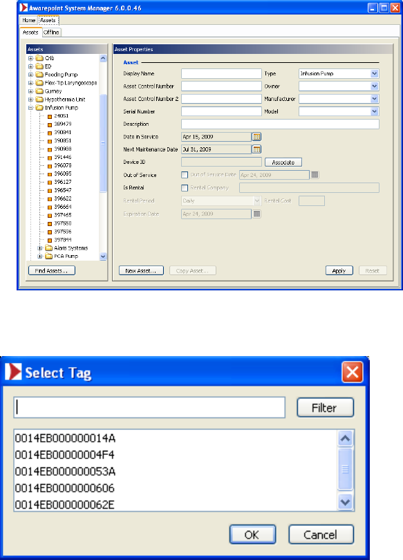
Adding Additional Assets After Installation 65
Installation Guide v2.3 – 5/10
Confidential and Proprietary ©2010, Awarepoint Corporation
2. Choose the New Asset button.
Figure 88 - Asset Properties
3. Choose the Associate button to display a list of Tags.
Figure 89 - List of Tags
4. Choose the correct Tag to associate with this asset.
5. Fill in the rest of the asset information and choose the Apply button.
The new asset will now be listed under the appropriate asset type.
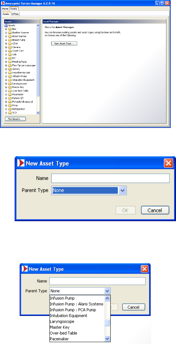
Adding Additional Assets After Installation 66
Installation Guide v2.3 – 5/10
Confidential and Proprietary ©2010, Awarepoint Corporation
11.3 Add a New Asset Type
Figure 90 - Offline Asset Manager
1. Choose the New Asset Type button.
Figure 91 - New Asset Type dialog box
2. Enter the new asset type name.
3. Choose the appropriate Parent Type from the drop-down list.
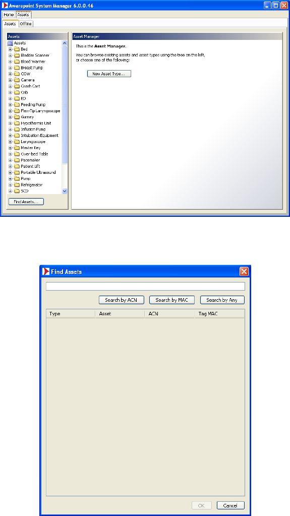
Adding Additional Assets After Installation 67
Installation Guide v2.3 – 5/10
Confidential and Proprietary ©2010, Awarepoint Corporation
11.4 Find an existing asset
Figure 92 - Offline Asset Manager
Choose the Find Assets button.
Figure 93 - Find Assets dialog box
Once you have found the asset, you can associate it with a specific Tag.

Troubleshooting 68
Installation Guide v2.3 – 5/10
Confidential and Proprietary ©2010, Awarepoint Corporation
12 Troubleshooting
12.1 Awarepoint Appliance
If the Appliance is not responsive, try the following steps:
1. If you are onsite, look at the unit and determine if there are any hardware
problems (bad PSU, hard drive, etc.). The front LCD window can indicate an
error message / number. Please see Appendix C which contains the
explanations for the server error messages.
2. If there are no hardware problems, try to ping the Appliance. If successful, then
connect to it via SSH and proceed to step 4. If not, go to step 3
3. Connect the serial port to the Appliance and login to it. If the serial port is not
responsive, attach a monitor and keyboard to the Appliance and login. If you do
not have access to a monitor and keyboard, restart the box by holding down the
power button for five seconds.
4. Restart the Appliance by holding down the power button for several seconds.
5. If all else fails, contact Awarepoint Technical Support.
12.2 Awarepoint Bridge
If the Bridge appears Red in the Positioning: Configuration tab or on the Awarepoint
Network Operations Center, the Bridge has a problem. Try the following steps:
1. From a computer on the same network as the Bridge, ping the Bridge’s IP
address. If this test passes, proceed to step 3. If this test fails, it is likely the
Bridge is disconnected from the network. Check that the Bridge is connected to
the Ethernet network.
2. From the same computer, open a web browser and go to the Bridge’s IP
address. See Appendix A for login information. Press the Restart Bridge
button and enter the password.
3. Check the status of the Bridge using the system manger. If it remains down ,
contact Awarepoint Technical Support.
On a B2 Bridge, the below error messages indicate the following problems:
Network Errors
“Ethernet error! Check Cable”
This can indicate a bad Ethernet connection or cable. Follow the cabling to the server
to check for a connectivity problem. If needed, use Network Analyzer to test the port
for more information.

Troubleshooting 69
Installation Guide v2.3 – 5/10
Confidential and Proprietary ©2010, Awarepoint Corporation
12.3 Awarepoint Sensor
If the Sensor appears Red in the Positioning: Configuration tab or on the Awarepoint
Network Operations Center, the Sensor has a problem. Try the following steps:
1. Verify the Bridge nearest the Sensor is functioning correctly. Verify the
Appliance is functioning correctly.
2. Verify that Sensor has most up-to-date Sensor firmware that is appropriate for
model of Sensor and for model Bridge that is being used on the network.
3. If multiple Sensors were down and they are all grouped together, likely these
were all routing through one Sensor and that Sensor lost connectivity. Wait
approximately one hour and check the status again. If the Sensors are still
down, proceed to step 4.
4. Verify that the Sensor is physically present. If so, then proceed.
5. Unplug and replug the Sensor. If it is still red, replace the Sensor. If another
Sensor is red in the same location, likely the Sensor is out of range of the next
nearest Sensor. Move the Sensor closer to the Sensors that are working.
CAUTION: To remove a Sensor that has been secured (taped) in place, use the
insulated blade screwdriver to first remove the electrical faceplate from the
wall, then separate the Sensor from the faceplate. NEVER reach behind the
Sensor in an effort to insert or remove it from the outlet as electrical shock may
occur if you contact the electrical prongs while they are still inserted in the
outlet. For insertion or removal, grasp the Sensor by the sides only.
12.4 Awarepoint Tag
If a Tag is listed as “missing,” it may be either out of the area or it may be
malfunctioning. Try the following steps:
1. Verify the Appliance, Bridge, and Awarepoint Sensors are properly working
throughout the coverage area.
2. Verify the Tag is in the coverage area.
3. Switch the slider on the Tag several times. Using Status Server, verify the tag is
listed as functioning (with a current last update date and time). If not, replace
the Tag. Please follow the current RMA process for Tag replacement(s).
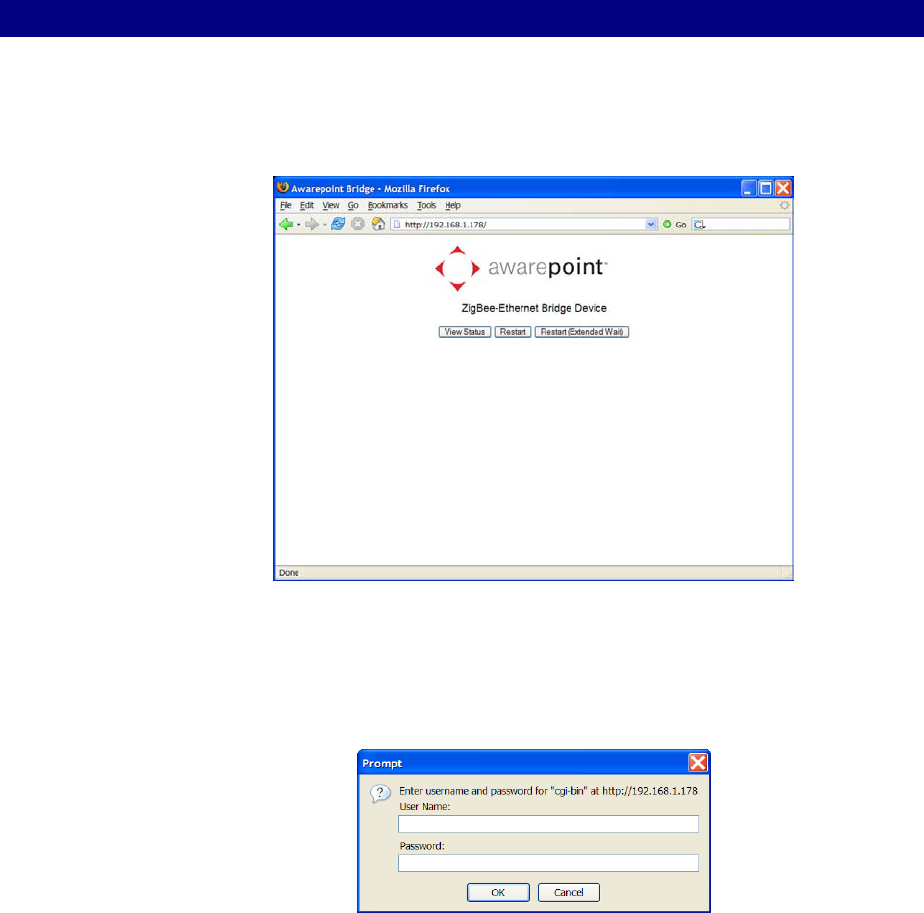
Appendix A – Awarepoint Bridge Web Interface 70
Installation Guide v2.3 – 5/10
Confidential and Proprietary ©2010, Awarepoint Corporation
Appendix A – Awarepoint Bridge Web Interface
The Bridge has a simple interface that is accessed by typing in the Bridge’s IP address
into a web browser. This interface can only be accessed if you are on the local
network. You will not be able to access the Awarepoint Bridge Web Interface from an
Internet connection.
Figure 94- Awarepoint Bridge Web Interface
Username: bridgeadmin
Password: last six digits of the Bridge’s MAC address.
Figure 95 - Awarepoint Bridge Password Prompt Dialog Box
You may also view the Bridge statistics using this web interface.
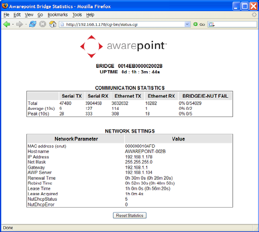
Appendix A – Awarepoint Bridge Web Interface 71
Installation Guide v2.3 – 5/10
Confidential and Proprietary ©2010, Awarepoint Corporation
Figure 96 - Awarepoint Bridge Statistics Page
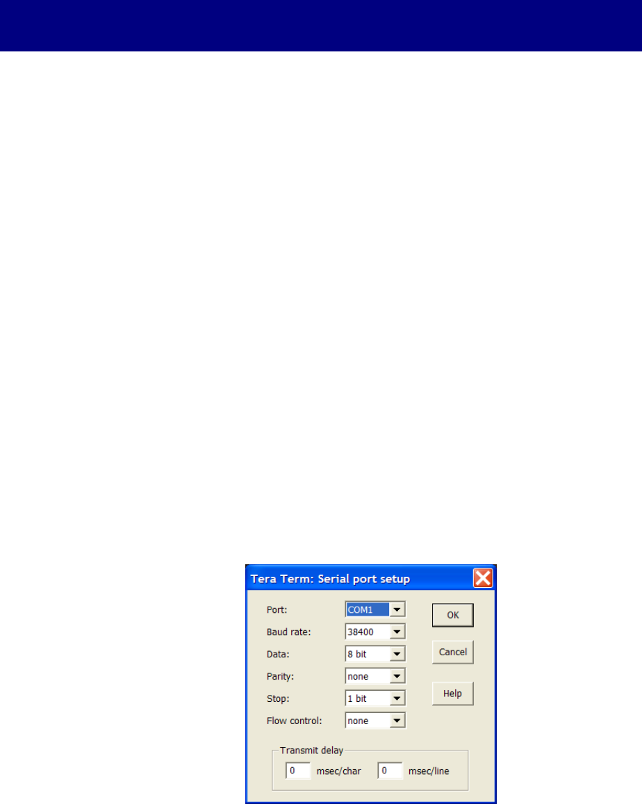
Appendix B – Complete Appliance Configuration Instructions 72
Installation Guide v2.3 – 5/10
Confidential and Proprietary ©2010, Awarepoint Corporation
Appendix B – Complete Appliance Configuration
Instructions
If you have not configured an Appliance before, please contact an Awarepoint
Professional Services engineer for guidance. This appendix is included only as a
reference, and should not be used without specific training and recommendations.
Connect to Awarepoint Appliance’s Serial Interface
If you have a keyboard and monitor connected to the Awarepoint Appliance, you may
skip this step.
1. Start the Appliance, and after it has booted (approx. 5-10 minutes) connect a
serial cable with null modem adapter between the Appliance and the computer
you will use to configure the Appliance (normally your laptop computer).
2. Open a terminal program (e.g. TeraTerm) and set the serial port on your
computer to:
▪ Baud: 38,400 baud
▪ Data Bits: 8
▪ Parity: None
▪ Stop Bits: 1
▪ Flow control: None
To do this in Tera Term, choose Setup: Serial Port and adjust the settings
appropriately for the port on your computer.
Note: the Port setting in the image below may be different, depending upon your
computer.
Figure 97 - Tera Term Serial Port Setup

Appendix B – Complete Appliance Configuration Instructions 73
Installation Guide v2.3 – 5/10
Confidential and Proprietary ©2010, Awarepoint Corporation
Login to the Awarepoint Appliance
Press return a few times and you should see the login prompt. Enter:
▪ Username: root
▪ Password: (to be provided by Awarepoint)
Verify the system date
1. Type in "date" and press enter.
2. If the date is not correct then run "date MMDDhhmmYYYY" to set the date.
Example: For 10-20-2009 13:01 type "date 102013012009".
3. Run "date" again to verify the date.
Configure the Awarepoint Software
Note: Normally the Awarepoint Appliance software has been has been preconfigured
prior to onsite installation and requires only the “awp-network-config.sh” utility.
If an HTTPS proxy is in place (normally there is none) a second utility, “awp-proxy-
config.sh”, is used to configure proxy services.
The utility “awp-init.sh” will perform the following sections in this Appendix and is
referred to below for completeness but is not normally required.
Network Configuration
Verify that the network cable is attached to interface “eth0.” On the PE1950 this is
labeled “Gb2.”
Run “awp-init.sh” to run the configuration utility. The script displays the main menu:
step 1 configure network
hostname: localhost.localdomain
1) configure hostname
2) configure eth0
3) configure dns
q) quit
Select option 2, “configure eth0” and enter the IP Configuration (q to quit):
eth0 is enabled
using dhcp
eth0 Link encap:Ethernet HWaddr 00:0C:29:18:FB:48
inet addr:192.168.1.175 Bcast:192.168.1.255 Mask:255.255.255.0
inet6 addr: fe80::20c:29ff:fe18:fb48/64 Scope:Link
UP BROADCAST RUNNING MULTICAST MTU:1500 Metric:1
RX packets:2746 errors:0 dropped:0 overruns:0 frame:0
TX packets:154 errors:0 dropped:0 overruns:0 carrier:0
collisions:0 txqueuelen:1000
RX bytes:291745 (284.9 KiB) TX bytes:16965 (16.5 KiB)

Appendix B – Complete Appliance Configuration Instructions 74
Installation Guide v2.3 – 5/10
Confidential and Proprietary ©2010, Awarepoint Corporation
Interrupt:177 Base address:0x1400
1) Use DHCP
2) Manually configure
3) Restart interface
4) Enable Device
5) Disable Device
q) quit
Select option 2, "Manually Configure," and enter the Awarepoint Appliance’s IP address
information.
IP Address: 192.168.1.173
Netmask: 255.255.255.0
Gateway (default route): 192.168.1.1
Press "q" to return to the main menu when asked.
changes were made restart network [y/n]?
Press “y.”
Select option 3, "configure dns," and enter the IP address of the dns Awarepoint
Appliance (q to quit):
local domain name:
-------------
nameAwarepoint Appliance list:
206.13.30.12
206.13.29.12
-------------
domain search order:
localdomain
-------------
1) change domain name
2) change nameAwarepoint Appliances
3) change domain search order
q) quit
Select option 4, "test network," to test the network settings. This will attempt to connect
to https://aps.awarepoint.com. If the test is successful there will be no output. You will
need to check the network settings if you see something like this:
Attempting to connect to https://aps.awarepoint.com
curl: (7) couldn't connect to host
Download Failed error #7. see |man curl| for more info.
Press "q" to return to the main menu.
Proxy Configuration
If there is no HTTPS proxy (normally, there is none) then just press "q" to continue.
Otherwise press "1" to set the proxy settings:
step 2 configure proxy
Proxy is not configured
1) change settings
2) disable proxy
3) test proxy settings
q) exit
1

Appendix B – Complete Appliance Configuration Instructions 75
Installation Guide v2.3 – 5/10
Confidential and Proprietary ©2010, Awarepoint Corporation
Proxy Awarepoint Appliance IP: 192.168.1.1
Proxy Awarepoint Appliance HTTP PORT: 8080
Proxy Awarepoint Appliance HTTPS PORT: 8080
Proxy Awarepoint Appliance FTP PORT: 8080
Proxy Username: <enter the proxy username>
Proxy password: <enter the proxy password>
Press "q" to return to the main menu.
Mysql Password Generation
Step 3 will generate a unique mysql root password. This password does not need to be
noted.
step 3 changing mysql root password
password changed
finished
press enter to continue
Root Password
Step 4 is very important. You MUST write down the root password
step 4 configure root password
Changing password for user root.
passwd: all authentication tokens updated successfully.
the new root password has been set to <something>
Do not press enter until you've written down the root password
Press enter to continue
Time zone Configuration
Note: Step 5 was omitted prior to IPS software version 4.0.
Step 5 will set the time zone. Choose the number, which matches the destination sites
time zone.
step 5 initialize timezone
1) America/Adak
2) America/Anchorage
3) America/Boise
4) America/Chicago
5) America/Denver
6) America/Detroit
7) America/Indiana/Indianapolis
8) America/Indiana/Knox
9) America/Indiana/Marengo
10) America/Indiana/Petersburg
11) America/Indiana/Vevay
12) America/Indiana/Vincennes
13) America/Juneau
14) America/Kentucky/Louisville
15) America/Kentucky/Monticello
16) America/Los_Angeles
17) America/Menominee
18) America/New_York
19) America/Nome

Appendix B – Complete Appliance Configuration Instructions 76
Installation Guide v2.3 – 5/10
Confidential and Proprietary ©2010, Awarepoint Corporation
20) America/North_Dakota/Center
21) America/Phoenix
22) America/Shiprock
23) America/Yakutat
24) Pacific/Honolulu
Enter ID:
Network Operations Center Registration
Step 6 will register with the Awarepoint Network Operations Center. You must have
sufficient access to be able to do this.
step 6 register with the Awarepoint Network Operations Center
Awarepoint Site Registration Script
Awarepoint Network Operations Center Username: <your Awarepoint Network Operations Center
username>
Awarepoint Network Operations Center Password: <your Awarepoint Network Operations Center
password>
Site Name: <the name of the site>
URL (https://aps.awarepoint.com/):
Register site with these values (y/n)
Enter your Awarepoint Network Operations Center username and password and the
name of the site.
Contact an Awarepoint Administrator for Site access. Otherwise you will not see this
site on your Awarepoint Network Operations Center home page
Test the Awarepoint Appliance
1. Open a web browser and navigate to http://<Awarepoint Appliance IP address>
For example, if the Appliance’s IP address is 10.0.2.31 then navigate to
http://10.0.2.31/SystemManager
2. You should see the Awarepoint logo. If you do not, try reconfiguring the
Appliance.

Appendix C – Server Error Codes 77
Installation Guide v2.3 – 5/10
Confidential and Proprietary ©2010, Awarepoint Corporation
Appendix C – Server Error Codes
The following is an excerpt from the Dell PowerEdge 1950 System Hardware Owner’s
Manual. It has been included as a reference for server error codes.