AwarePoint S2 Equipment Location Transceiver User Manual
AwarePoint Corporation Equipment Location Transceiver
User Manual

Awarepoint Sensor S2
Installation Manual
Date: 02/14/2008
AwarepointCorporation
225Broadway,Suite1670
SanDiego,CA92101
www.awarepoint.com
Document History
Date Author Changes
02/14/2008 Derek Smith Initial Draft
1
Awarepoint Sensor S2 © 2008 Awarepoint Corporation
Installation Manual
Copyright
Copyright2008AwarepointCorporation
Allrightsreserved.Thisproductordocumentisprotectedbycopyrightanddistributedunder
licensesrestrictingitsuse,copying,distribution,anddecompilation.Nopartofthisproductor
documentmaybereproducedinanyformbyanymeanswithoutpriorwrittenauthorizationof
Awarepointanditslicensors,ifany.
Awarepoint,theAwarepointlogo,andReal‐timeAwarenessSolution,aretrademarksor
registeredtrademarksofAwarepointCorporationintheUnitedStatesandinothercountries.
FCCCompliance
AwarepointSensormodelS2FCCID:UAG‐S2
ThisdevicecomplieswithPart15oftheFCCRules.Operationissubjecttothefollowingtwo
conditions:(1)thisDevicemaynotcauseharmfulinterferenceand(2)thisDevicemustaccept
anyinterferencereceived,includingInterferencethatmaycauseundesiredoperation.
CAUTION:Changesormodificationsnotexpresslyapprovedbythepartyresponsiblefor
compliancecouldvoidtheuser'sauthoritytooperatetheequipment.
CAUTION:Thismanualdescribesinstallationproceduresforelectricalequipment.Proper
precautionsarerequired.Particularattentionshouldbegiventotexthighlightedwiththe
followingsymbol:

2
Awarepoint Sensor S2 © 2008 Awarepoint Corporation
Installation Manual
TableofContents
SectionPage
1Introduction ............................................................................................... 3
1.1Overview .............................................................................................. 3
1.2Preparing for Installation – Read this First! .......................................... 3
1.2.1Tools and Supplies .................................................................................................. 3
1.2.2Information ............................................................................................................... 3
1.3System Components ............................................................................ 4
1.3.1Sensor ..................................................................................................................... 4
2Awarepoint Sensor Installation ................................................................ 5
2.1Physical Installation ............................................................................. 5
2.2Secure Awarepoint Sensors ................................................................. 6
2.3Verify the Sensor Connects to the Network ......................................... 6
2.4Place Awarepoint Sensor on Map ........................................................ 6
3Troubleshooting ...................................................................................... 30
3.1Awarepoint Sensor ............................................................................. 30

3
Awarepoint Sensor S2 © 2008 Awarepoint Corporation
Installation Manual
1 Introduction
Customersupport:1‐888‐TAGIT‐NOW
1.1 Overview
ThissysteminstallationmanualisforanAwarepointemployeeorAwarepointtrained
serviceproviderwhointendstoinstalltheAwarepointSensor.
1.2 Preparing for Installation – Read this First!
1.2.1 Tools and Supplies
Priortoinstallation,youwillneedthefollowingtoolsandsupplies:
1. SmallEthernetswitches(ifnecessarytopluginyourlaptop)
2. HospitalGradePowerStrips(ifnecessarytoputanAwarepointSensorinanoutlet
thatisfull)
3. InstallationKit,consistingofthefollowing:
SerialCablewithNullModemAdapterandF‐FGenderChanger
EthernetCable
Zip‐Ties
Double‐SidedTapeMountingStrips
4. InstallationTools,consistingofthefollowing:
Laptop
Terminalemulatorsoftware(werecommendTeraTerm,availablefrom
http://www.tucows.com/preview/195282)
USBtoSerialadapter(iflaptopdoesnothaveaserialport)
Wirecutters–fortrimmingZipties
Insulatedbladescrewdriver–forelectricalfaceplates,ifyoumakeanerror
whentapingtheAwarepointSensorsdown
Phillipsscrewdriver–forinstallingtheAwarepointAppliance
1.2.2 Information
Priortoinstallation,youwillneedthefollowinginformation:
1. Mapsforallfloors,inpaperandelectronicformatwithcoverageareaoutlined
2. AwarepointBridge
IPAddressing:DHCPorStatic.IfusingStaticaddressingthen:IPAddress,Default
Gateway,andSubnetMask.
IPAddressofAwarepointAppliance
4
Awarepoint Sensor S2 © 2008 Awarepoint Corporation
Installation Manual
Location,withanEthernetportthathasbeentestedandconfiguredtowork
with10Base‐T,fullduplexEthernet.(A10/100autosensesettingshouldbe
adequate)
1.3 System Components
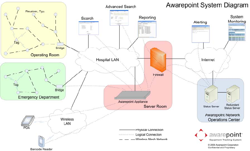
TheAwarepointReal‐timeAwarenessSolutionconsistsofseveralcomponentsasshown
inthediagrambelow.Thepartsofthesystemthatrequireinstallationinclude
AwarepointTags,AwarepointSensors,AwarepointBridges,andtheAwarepoint
Appliance.TheAwarepointAppliancecontainsallsoftwarenecessaryforsystem
operation.
Figure 1-1.1: System Diagram
1.3.1 Sensor
ThereareseveralmodelsofSensors.

5
Awarepoint Sensor S2 © 2008 Awarepoint Corporation
Installation Manual
Figure 1.1-2: Awarepoint Sensor model R1 Figure 1.1-3: Awarepoint Sensor model S2
TheSensormodelR1displaysitsstatusthreevisualindicatorsintheformofLight
EmittingDiodes(LEDs).ThetopmostLEDindicatesnetworkstatus.Redindicatesthat
theSensorcannotcommunicatewithanyotherdevices.Yellowindicatesthatitcan
communicatewiththeBridgebutnottheAppliance.Greenmeansthatitcan
communicatewiththeBridgeandAppliance.ThemiddleLEDindicatesnetworkactivity.
Innormaloperation,itwilloccasionallyblink.ThebottomLED(blue)indicatespower.If
thedeviceispluggedintoanoutletthathaspowerthenitisilluminated.
TheSensormodelS2displaysitsstatuswithoneLEDvisualindicator.Ifitisoffthenthe
deviceisdefectiveornotpowered.RedindicatesthattheSensorcannotcommunicate
withanyotherdevices.YellowindicatesthatitcancommunicatewiththeBridgebut
nottheAppliance.GreenmeansthatitcancommunicatewiththeBridgeandAppliance.
2 Awarepoint Sensor Installation
Sensorsneedtobelocatedthroughoutthecoveragearea,includingalongthe
perimeter.WheninstallingSensors,beginbyinstallingSensorsneartheBridgeandwork
progressivelyoutwardinconcentriccircles.Inthismanner,youwillminimizethe
numberofSensorsthatmustbemoved.
PriortoinstallingtheSensors,theApplianceandBridgemustbeinstalledcorrectly.
2.1 Physical Installation
TheSensorsareinstalledinstandardelectricalpowerreceptacles.Priortoinstallingthe
Sensoryoumustlocateapoweredoutlet.Verifythatthereceptaclehaspowerbyusing
anelectricaltester.
6
Awarepoint Sensor S2 © 2008 Awarepoint Corporation
Installation Manual
2.2 Secure Awarepoint Sensors
Onceyouhaveoptimizedthemeshnetwork,removetheSensor;applydouble‐sided
tapestriptothetopoftheoutputfaceplateandreinstalltheSensor,pressingfirmlyto
adhere.
CAUTION:Toremoveasensorthathasbeensecuredinplace,usetheinsulated
bladescrewdrivertofirstremovetheelectricalfaceplateandsensorfromthewall,
thenseparatethesensorfromthefaceplate.NEVERreachbehindthesensorinan
efforttoinsertorremoveitfromtheoutletaselectricalshockmayoccurifyou
contacttheelectricalprongswhiletheyarestillinsertedintheoutlet.Forinsertionor
removal,graspthesensorbythesidesonly.
2.3 Verify the Sensor Connects to the Network
OnceyouplugtheSensorintoanoutlet,itwillattempttoconnecttotheAwarepoint
network.Thisprocesswilltakeapproximatelyoneminute.WhentheSensorhas
completedthisprocess,theNetworkLEDwillbeilluminatedGreen.IftheSensoris
unabletoconnecttothenetwork(outofrangeofanetworkornetworknotproperly
configured),theSensorwillcontinuetoattempttoconnecttothenetworkandthe
NetworkLEDwillbeRed.
OncetheSensorhassuccessfullyconnectedtothenetwork,marktheSensorlocation
anditsMACaddressonapapercopyofthemap.
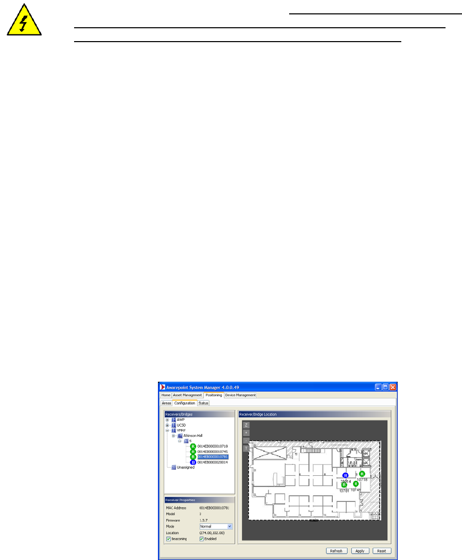
2.4 Place Awarepoint Sensor on Map
OpentheSystemManagerandclickonthePositioning:Configurationtab.TheSensor
youjustinstalledshouldshowupintheUnassignedsectionofthedevicetree.Ifitis
functioningcorrectly,theiconfortheSensorshouldbegreen.
Inthedevicetree,expandtheCampusandBuildingsothatyoucanseethefloor.Click
onthefloortodisplaythemapforthefloor.DragtheSensoriconontothemapand
placeitwhereitislocated.
Figure2‐1:Positioning:ConfigurationTab‐PlacingAwarepointSensor
30
Awarepoint Sensor S2 © 2008 Awarepoint Corporation
Installation Manual
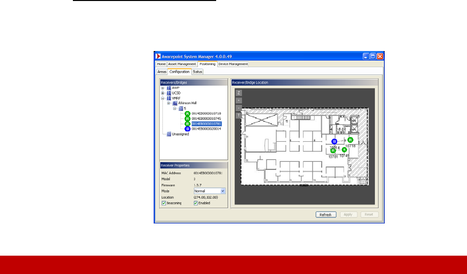
Finally, click the Apply button.
ContinuetoplaceallSensors.Astheyareplaced,theywilljointhenetwork.Some
routinglineswillbedisplayedasshownbelow.
Figure2‐2:Positioning:ConfigurationTab‐PlacingallAwarepointSensors
3 Troubleshooting
CustomerSupport:1‐888‐TAGIT‐NOW
3.1 Awarepoint Sensor
IftheSensorappearsRedinthePositioning:ConfigurationtaborontheAwarepoint
NetworkOperationsCenter,theSensorhasaproblem.Trythefollowingsteps:
1. VerifytheBridgenearesttheSensorisfunctioningcorrectly.VerifytheApplianceis
functioningcorrectly.
2. IfmultipleSensorsweredownandtheyareallgroupedtogether,likelythesewere
allroutingthroughoneSensorandthatSensorlostconnectivity.Wait
approximatelyonehourandcheckthestatusagain.IftheSensorsarestilldown,
proceedtostep3.
3. VerifythattheSensorisphysicallypresent.Ifso,thenproceed.
4. UnplugandreplugtheSensor.Ifitisstillred,replacetheSensor.IfanotherSensoris
redinthesamelocation,likelytheSensorisoutofrangeofthenextnearestSensor.
MovetheSensorclosertotheSensorsthatareworking.