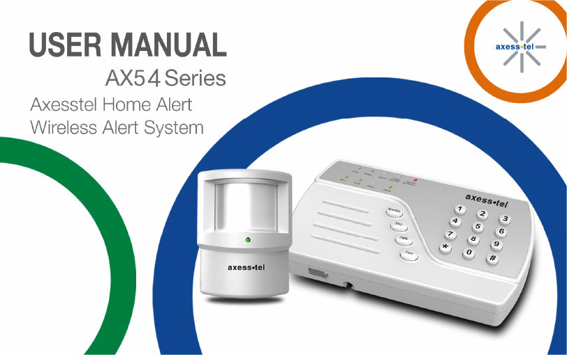
Axesstel AX54 CDMA 1x Alert System (Main Unit) User Manual AX54 Series Rev4

Axesstel Inc CDMA 1x Alert System (Main Unit) AX54 Series Rev4

User Manual

 0
 1  Important Notice Due to the nature of wireless communications, transmission and reception of data can never be  guaranteed.  Data may  be delayed, corrupted (i.e.,  have  errors) or  be  totally lost.  Although significant  delays  or  losses of  data  are rare when  wireless devices are used  in  a  normal  manner  with  a  well-constructed  network,  the  device  should  not  be used in situations where failure to transmit or receive data could result in damage of any kind to the user or any other party, including but not limited to personal injury, death or loss of property and this item is used under conditions greater than the body 20cm away. Axesstel  accepts  no  responsibility  for  damages  of  any  kind  resulting  from  delays  or errors  in  data  transmitted  or  received  using  the  Axesstel  device  or  for  failure  of  the Axesstel device to transmit or receive such data.
 2 Safety Precautions •  Only  use  the  supplied  power  adaptor,  and  do  not  use  the  power  adaptor  in temperatures over 40oC, and only use in a dry location •  Only use 9V batteries in the main unit and the motion sensors, as there is a risk of explosion if an incorrect battery type is used •  Please dispose of any used 9V batteries at a proper facility •  Do not operate the device:  o  In areas where blasting is in progress o  Where explosive atmospheres may be present o  Near medical equipment o  Near life support equipment or any equipment that may be susceptible to any form  of radio interference. In such areas, the device MUST BE POWERED  OFF.  The  Axesstel  router  can  transmit  signals  that  could interfere with this equipment.
 3 Limitation of Liability The  information  in  this  manual  is  subject  to  change  without  notice  and  does  not represent a commitment on the part of Axesstel. AXESSTEL  SPECIFICALLY  DISCLAIMS  LIABILITY  FOR  ANY  AND  ALL  DIRECT, INDIRECT,  SPECIAL,  GENERAL,  INCIDENTAL,  CONSEQUENTIAL,  PUNITIVE  OR EXEMPLARY  DAMAGES  INCLUDING,  BUT  NOT  LIMITED  TO,  LOSS  OF  PROFITS OR  REVENUE  OR  ANTICIPATED  PROFITS  OR  REVENUE  ARISING  OUT OF  THE USE OR INABILITY TO USE ANY AXESSTEL PRODUCT, EVEN IF AXESSTEL HAS BEEN  ADVISED  OF  THE  POSSIBILITY  OF  SUCH  DAMAGES  OR  THEY  ARE FORESEEABLE OR FOR CLAIMS BY ANY THIRD PARTY. Notwithstanding  the  foregoing,  in  no  event  shall  Axesstel  aggregate  liability  arising under or in connection with the Axesstel product, regardless  of the number of events, occurrences, or claims giving rise to liability.
 4 Table of Contents  1 .... Introduction ............................................................................................. 6 2 .... Product Overview .................................................................................... 6 3 .... Using your AX54 ..................................................................................... 9 3.1 Package Contents ............................................................................ 9 3.2 Knowing your Main Unit .................................................................... 9 3.3 LEDs ................................................................................................ 9 4 .... Using your AX54 ..................................................................................... 11 4.1 Battery Installation / UIM Card Installation into Main Unit ................... 111 4.2 Battery Installation into Motion Sensor .............................................. 122 4.3 Connecting the Power Adaptor ......................................................... 13 4.4 Placement of Main Unit / Motion Sensor............................................ 14 4.4.1 Main Unit .................................................................................... 14 4.4.2 Motion Sensor ............................................................................ 14 4.5 UIM Card .......................................................................................... 14 4.6 Changing the Default Password ........................................................ 16 4.7 Adding / Removing Motion Sensors .................................................. 17
 5 4.8 Adding / Removing SMS Numbers .................................................... 18 4.9 Adding / Removing Call Numbers ..................................................... 20 4.10 Arming / Disarming the AX54 ............................................................ 21 4.10.1 Arming the AX54 ...................................................................... 22 4.10.2 Disarming the AX54 .................................................................. 24 4.11 Entry / Exit Delay .............................................................................. 25 4.11.1 Entry Delay............................................................................... 25 4.11.2 Exit Delay ................................................................................. 26 4.12 Panic Button ..................................................................................... 26 4.13 Factory Reset ................................................................................... 27 5 .... Operating Specifications ......................................................................... 28 5.1 Main Unit .......................................................................................... 28 5.2 Motion Sensor (AI100) ...................................................................... 32
 6  1  Introduction This user manual will help you place, configure and use your AX54 Alert System. 2  Product Overview The AX54 is an easy to install, use and maintain alert system, which can provide peace of mind and security without the need for an expensive security contract.   Some features described in this manual may not be supported by your service provider or may not be available with your network account. For details of the services and accounts available, contact your service provider.
 7 SMS / Call Alerts if the Motion Sensor is Triggered Notify up to 8 friends and neighbors via call or SMS when motion is detected to increase chances of a close-by responder.  You can program up to 3 SMS numbers and 5 call numbers.  Emergency Backup Battery An AC adaptor with a 9V backup battery provides continued functionality in the event of a power outage.  Remote Control Convenience The arming and disarming of the AX54 Alert System can be triggered by keypad input or by sending an SMS from one of your registered numbers.  Affordable, Easy to Setup, Configure, and Use A basic UIM Card and prepaid / postpaid subscription provides increased peace of mind. To setup the device, you will simply need to insert the UIM Card, and ensure network coverage.  You are then ready to start using your AX54 Alert system.
 8 Easy to use Main Unit 9 LED indicators represent the product status.  The unit is also very easy to program and to modify the list of SMS / Call contacts.
 9  3  Using your AX54 3.1  Package Contents •  1x Main Unit •  2x Motion Sensors with brackets •  1x Power Adaptor 3.2  Knowing your Main Unit Your AX54 is designed to be wall mounted, or it can simply be placed on a shelf.  All the LEDs are easily visible while the power cord will connect at the back. 3.3  LEDs The AX54 has 9 LEDs to determine status of the device. The functionality of the LEDs can be found in the table below.
 10 LED  Green  Flashing Green  Red  Off Power  Device is Turned On  -  -  Device is Off Battery  Battery power is Full / Medium  -  Battery  Power is Low No Battery is installed Signal Registered to the network and signal level is good Signal is poor  -  No network signal Setting  / Register In process of  setting Alarm  In register status -  Not in Setting / Registering Mode Arming /  Disarming  -  -  Alarm is Armed  Alarm is Disarmed Zone 1  Armed  -  Alarm Detected  Disarmed Zone 2  Armed  -  Alarm Detected  Disarmed Zone 3  Armed  -  Alarm Detected  Disarmed Zone 4  Armed  -  Alarm Detected  Disarmed
 11  4  Using your AX54 4.1  Battery Installation / UIM Card Installation into Main Unit  Your AX54 main unit may need a UIM Card so that it can communicate with the wireless network.  It also supports battery backup. Please follow the instructions below to install the UIM Card and the 9V battery.  Note: It is advisable to install your UIM Card before you install the 9v battery.
 12 4.2  Battery Installation into Motion Sensor To install the battery into the Motion Sensor please follow the instructions below.
 13 4.3  Connecting the Power Adaptor To connect the power adaptor, please follow the instructions below.
 14 4.4  Placement of Main Unit / Motion Sensor 4.4.1  Main Unit The keypad should be placed near the entry / exit point of the house.  4.4.2  Motion Sensor Place on shelves or walls to detect motion within 50 meters, great for rooms with lots of windows. 4.5  UIM Card  PLEASE NOTE: THIS SECTION ONLY APPLIES TO DEVICES REQUIRING UIM CardS FOR OPERATION Unlocking your UIM Card The UIM Card for your device may have a PIN code enabled as default.  When you insert the UIM Card and power on the unit, if the battery LED flashes green and red, this indicates that your UIM Card is locked with a PIN code.  To unlock the card please enter the command below *#→password→07->PIN Code→Func Key
 15  Activate/ Deactivate the PIN Code To toggle between activating and deactivating the PIN Code, please enter the following on your keypad *#→password→07->PIN Code→Func Key  Changing your PIN Code You may want to change your UIM Card PIN code to something more memorable to do this you can enter the command below *#→password→08->Existing PIN Code*→New PIN Code→ Func Key  PUK Code If you enter an incorrect PIN code 3 times, then you will need to enter your PUK code in order to unlock your device. The battery keypad will flash slowly between green and red.  To enter your PUK code please enter the command below *#→password→09->PUK Code*→New PIN Code→ Func Key
 16  4.6  Changing the Default Password Now that the battery is installed and the power adaptor connected you are ready to use some of the more advanced features of the AX54. To change the default password please follow the instructions below.  Using your keypad please enter the following *#→password→00->new password*→new password→Func Key      NOTE: IT IS ADVISABLE TO CHANGE YOUR PASSWORD AS SOON AS YOU CONNECT THE UNIT  *Default password is 1234.  So if you wanted to change your password to 4897, then you would enter the following: *#1234004897*4897 <Func>
 17  4.7  Adding / Removing Motion Sensors To add motion sensors to the AX54 please follow the instructions below.  Up to 64 Motion sensors can be added across 4 zones.  *#→password→71→Func Key  Trigger the sensor that you want to put in zone1  *#→password→72→Func Key   Trigger the sensor that you want to put in zone2  *#→password→73→Func Key   Trigger the sensor that you want to put in zone3  *#→password→74→Func Key   Trigger the sensor that you want to put in zone4   Please note that you need to trigger the desired sensor within 30 seconds so that it registers correctly within the desired zone. To add additional sensors in your desired zone please repeat the instructions above.  You can have up to 16 sensors per zone.  To remove the motion sensors please follow the instructions below. *#→password→81→Func Key       zone1
 18 *#→password→82→Func Key       zone2 *#→password→83→Func Key       zone3 *#→password→84→Func Key       zone4  Please note that removing sensors will remove all the sensors in the specific zone.  4.8  Adding / Removing SMS Numbers When your alarm is triggered in any zone, you can choose to send an SMS to up to 3 numbers.  To add the SMS numbers into your AX54 please follow the instructions below.  *#→password→11→SMS Num.1*→SMS Num.1→Func Key *#→password→12→SMS Num.2*→SMS Num.2→Func Key *#→password→13→SMS Num.3*→SMS Num.3→Func Key  Example:  Adding the first SMS number-  *#→password→11→1234567890*→1234567890→Func Key
 19 Please note that you have to enter the desired number twice.  The number that you entered will need to match. If the numbers do not match then the unit will beep 3 times.  If the numbers match then you will hear 2 beeps.  To remove the SMS numbers please enter the details below. *#→password→20→Func Key   Delete all SMS telephone numbers *#→password→21→Func Key  Delete number 1 *#→password→22→Func Key   Delete number 2 *#→password→23→Func Key  Delete number 3
 20  4.9  Adding / Removing Call Numbers   When your alarm is triggered as well as sending SMS, the AX54 will also dial 5 numbers of your choice.  It is important to note that as the AX54 has no microphone or speaker no conversation will be permissible.   To add numbers please follow the instructions below.  *#→password→31→Tel Num.1*→Tel Num.1→Func Key *#→password→32→Tel Num.2*→Tel Num.2→Func Key *#→password→33→Tel Num.3*→Tel Num.3→Func Key *#→password→34→Tel Num.4*→Tel Num.4→Func Key *#→password→35→Tel Num.5*→Tel Num.5→Func Key  Example:  Adding the first telephone number-  *#→password→31→1234567890*→1234567890→Func Key
 21 Please note that you have to enter the desired number twice.  The number that you entered will need to match. If the numbers do not match then the unit will beep 3 times.  If the numbers match then you will hear 2 beeps.  To remove the phone numbers please follow the instructions below. *#→password→40→Func Key   Delete all telephone numbers *#→password→41→Func Key   Delete number 1 *#→password→42→Func Key   Delete number 2 *#→password→43→Func Key   Delete number 3 *#→password→44→Func Key   Delete number 4 *#→password→45→Func Key   Delete number 5 4.10  Arming / Disarming the AX54 Now that the AX54 is installed, the motion sensors have been added, and the SMS / Call numbers have been input you can now start using your AX54 as an alert system. There are three arming modes within the AX54, Siren Mode, Silent Mode and Stay Mode.  In all modes SMS / Calls will automatically be sent.
 22 4.10.1   Arming the AX54  Siren Mode In Siren mode, when the motion sensors are triggered, it will emit a high pitched continuous beep, until the unit is disarmed.  To activate Siren mode enter the following:  *#→password→01->Arming Key  Silent Mode In Silent mode, when the alarm is triggered the high pitched continuous beep will not sound making the intruder unaware that the alarm has been triggered, although SMS / Calls will be sent.  To activate Silent mode enter the following: *#->password->02->Arming Key
 23  Stay Mode Occasionally you may want to alarm only a certain part of your house, and this can be achieved by using Stay mode.  Please note that Zone 4 will only be triggered when using stay mode. In Stay mode, you can activate your alarm so that any motion in zones one, two or three will not trigger the alarm, but if there is any movement in zone four then the alarm will be triggered.  In Stay mode you can choose whether the device emits a beep or stays silent when the alarm is triggered. To activate Stay mode enter the following:  *#→password→01->Stay Key    Stay Beep Mode *#->password->02->Stay Key    Stay Silent Mode  Remote Arming You can also arm the AX54 remotely via SMS.  To do this the mobile number that you use will need to be programmed as one of the three SMS numbers.  To arm the AX54 by SMS you will simply need to send a text message saying ‘Arm Alarm’ to the number that corresponds to the UIM that is placed in the AX54.
 24  4.10.2  Disarming the AX54 When disarming the AX54, you can disarm in multiple ways, and these are described below.  Normal Disarming To disarm the AX54 in a normal manner enter the following: *#->password->05->Arming Key   Normal disarming  Duress Disarming If you are forced to disarm the unit under duress, then SMS / Calls will still be made to the numbers that are stored in your device. Disarm under duress by entering the following: *#→password→03->Arming Key  Duress disarming
 25 Remote Disarming You can also disarm the AX54 remotely via SMS.  To do this the mobile number that you use to disarm the AX54 will need to be programmed as one of the three SMS numbers.  To disarm the AX54 by SMS you will simply need to send a text message saying ‘Disarm Alarm’ to the number that corresponds to the SIM that is placed in the AX54.  4.11  Entry / Exit Delay You can modify the entry / exit delay to suit your needs. 4.11.1  Entry Delay No Entry Delay  *#→password→50→Func Key  15 Seconds -  *#→password→51→Func Key 30 Seconds -   *#→password→52→Func Key 45 Seconds -   *#→password→53→Func Key
 26 4.11.2  Exit Delay  No Exit Delay  *#→password→60→Func Key 30 Seconds -   *#→password→61→Func Key 60 Seconds -   *#→password→62→Func Key 90 Seconds -   *#→password→63→Func Key 120 Seconds -   *#→password→64→Func Key 4.12  Panic Button Your AX54 features a panic button, that when pressed will immediately activate the siren, as well as alerting your friends and neighbors via SMS and Calls.   To activate the panic button simply press the ‘PANIC’ button which is located on your main unit. Please note: Once the panic button has been activated it can only be stopped by removing the power adaptor and removing the battery (if installed).
 27 4.13  Factory Reset If your unit malfunctions or develops any form of software fault then it may be necessary to perform a factory reset. To perform a factory reset please enter the following: *#→password→90→Func Key
 28 5  Operating Specifications For ASK 433MHz,the Main Unit is only for RX function without TX function, and Motion Sensor (AI100) is only for TX function without RX function 5.1  Main Unit  Item  Description Main CPU  M0516LBN Module  QSC6055 Cellular 800  Band Frequency  TX:  824MHz ~ 849MHz RX: 869MHz ~ 894MHz
 29 Carrier spacing  Channel Spacing 30KHz Channel Band width : 1.23MHz Maximum output power      300mW (24.7dBm) RSSI  Sensitivity and Dynamic Range : -104dBm ~ -25dBm < FER = 0.5% PCS 1900  Band Frequency  TX: 1850MHz ~ 1910MHz RX: 1930MHz ~ 1990MHz Carrier spacing  Channel Spacing : 50KHz Channel Band width : 1.23MHz Maximum output power         300mW (24.7dBm)
 30 RSSI  Sensitivity and Dynamic Range : -104dBm ~ -25dBm < FER = 0.5% Form Factor  Molex connector 80PIN Dimension  36.2*30*3.2mm Antenna  ASK433M Spring antenna CDMA  CDMA Dual LED   9
 31 Key  16 SMS number  3 sets phone number CALL number  5 sets phone number Zone number  4 zones Power adapter  5V/2A Battery  9V ASK 433Mhz    Band Frequency  433.82Mhz-434.02Mhz Carrier spacing  0.2MHz RSSI  < -110dBm Working Temperature  -10~+50oC Storage Temperature  -20~+70oC Humidity  5% to 95%
 32 5.2  Motion Sensor (AI100)  AP  BS0001 Detection mode  Passive infrared signal Key  Molex connector 80PIN Antenna  ASK433M Spring antenna Detection range  6-8m    LED  Red & Green Key  Not support Tamper switch  Support Battery  9V ASK 433Mhz    Band Frequency  433.82Mhz-434.02Mhz
 33 Carrier spacing  0.2MHz Maximum output power  4dB RSSI  < -110dBm Working Temperature  -10~+50oC Storage Temperature  -20~+70oC Humidity  5% to 95%
 34   AXESSTEL ALERT PRODUCTS CONSUMER WARRANTY AND LIMITATION OF LIABILITY THE  AXESSTEL  ALERT  PRODUCT  THAT  YOU  HAVE  PURCHASED,  WHEN  PROPERLY  INSTALLED,  CAN  BE USED TO DETECT MOTION IN A SPECIFIED AREA AND PROVIDE AN ALERT TO TELEPHONES OR PERSONAL DIGITAL ASSISTANTS THAT YOU SPECIFY.  THE PRODUCT IS DESIGNED SOLELY TO PROVIDE AN ALERT.  IT DOES NOT PROVIDE SECURITY, OR PREVENT INTRUSION, THEFT OR CRIME.   THE PRODUCT  IS  NOT  A  SECURITY  SERVICE,  ALERTS ARE  SENT  ONLY  TO  THE  DEVICES  YOU SPECIFY.  THEY ARE NOT  MONITORED  BY AXESSTEL, THE TELEPHONE COMPANY, LAW ENFORCEMENT  OR OTHER AGENCIES.   ALERTS ARE SENT OVER THE PUBLIC WIRELESS TELEPHONE NETWORK.  INTERRUPTION OF TELEPHONE SERVICE WILL PREVENT TRANSMISSION OF ALERTS.     LIMITED  WARRANTY.  FOR  PERIOD  OF  [APPLICABLE  WARRANTY  PERIOD],  AXESSTEL  WARRANTS  THAT THE ALERT PRODUCT SHALL (I) BE FREE FROM DEFECTS IN DESIGN, MATERIALS OR WORKMANSHIP, (II) CONFORM  TO  ITS  PRODUCT  SPECIFICATIONS  AND  (III)  BE  COMPLIANT  WITH  ITS  WIRELESS COMMUNICATION  STANDARD  (CDMA  1X,  EVDO,  GSM,  GPRS  AND  EDGE,  AS  APPLICABLE).    FOR  ANY
 35 PRODUCTS  THAT  FAIL  TO  MEET  THE  FOREGOING  WARRANTY,  AXESSTEL,  SHALL  REPAIR  OR  REPLACE SUCH  PRODUCTS,  IN  ITS  DISCRETION,  SO  THAT  ANY  DEFECTIVE  PRODUCT  OR  ANY  REPLACEMENT PRODUCT SHALL CONFORM TO THE WARRANTY.   IF  AXESSTEL  CANNOT  CURE  ANY  DEFECT  ON  COMMERCIALLY  REASONABLE  TERMS,  AXESSTEL  SHALL REFUND THE VALUE  OF THE NON-CONFORMING  PRODUCT  WITHIN FORTY- FIVE (45) DAYS. EXCEPT FOR THE FOREGOING WARRANTY, AXESSTEL MAKES NO WARRANTIES, EXPRESS OR IMPLIED, WITH RESPECT TO THE ALERT PRODUCT, AND SPECIFICALLY DISCLAIMS ANY WARRANTIES INCLUDING BUT NOT LIMITED TO  ANY  WARRANTY  OF  MERCHANTABILITY  OR  FITNESS  FOR  A  PARTICULAR  PURPOSE  OR  AGAINST INFRINGEMENT, OR ANY EXPRESS OR IMPLIED WARRANTY ARISING OUT OF TRADE USAGE OR OUT OF A COURSE OF DEALING OR COURSE OF PERFORMANCE AXESSTEL  DOES NOT REPRESENT  OR WARRANT THAT THE PRODUCT WILL OPERATE ERROR FREE, OR THAT THE PRODUCT WILL NOT BE DISABLED, COMPRISED OR CIRCUMVENTED (BY DISABLING TELEPHONE SERVICE OR IN SOME OTHER WAY).  AXESSTEL DOES NOT WARRANT THAT THE PRODUCT WILL DETECT OR PREVENT ALL INTRUSION, LOSS OF PROPERTY OR PERSONAL INJURY OR BURGLARY, HOLD-UP, FIRE, OR  MEDICAL  PROBLEM;  OR  THAT  THE  PRODUCT  WILL  IN  ALL  CASES  PROVIDE  THE  PROTECTION  FOR WHICH IT IS INTENDED.
 36 LIMITATION  OF  LIABILITY.      AXESSTEL  NOT  BE  LIABLE  TO  YOU  UNDER  ANY  CIRCUMSTANCE  FOR INCIDENTAL,  CONSEQUENTIAL OR SPECIAL DAMAGES, ARISING OUT OF  THE  USE  OR INABILITY TO USE, ANY OF THE ALERT PRODUCTS OR COMPONENTS.  AXESSTEL WILL NOT BE RESPONSIBLE FOR ANY LOSS OF  PROPERTY,  DAMAGE  TO  PROPERTY,  PERSONAL  INJURY,  DEATH  OR  OTHER  INCIDENTAL  DAMAGES, HOWEVER CAUSED, ARISING OUT OF THE USE OR INABILITY TO USE, ANY OF THE ALERT PRODUCTS OR COMPONENTS.  ANY LIABILITY OF AXESSTEL TO YOU, AND YOUR SOLE AND EXCLUSIVE REMEDY, FOR ANY CLAIM ARISING OUT OF THE USE OR PURCHASE OF THE PRODUCT (WHETHER  IN CONTRACT, TORT, OR OTHERWISE) WILL NOT EXCEED THE PURCHASE PRICE PAID FOR THE PRODUCT WHICH IS THE SUBJECT OF SUCH CLAIM OR CAUSE OF ACTION. NOT INSURANCE.  AXESSTEL IS NOT AN INSURER AND IS NOT RESPONSIBLE FOR ACTS OR OMISSIONS OF OTHERS  OR  FOR  EVENTS  BEYOND  ITS  CONTROL.   THE  PURCHASE  PRICE  FOR  THE  PRODUCT  HAS  NO RELATIONSHIP TO THE VALUE, IN WHOLE OR IN ANY PART, ANY LOSS, DAMAGE, INJURY OR DEATH WHICH MIGHT RESULT TO YOU  OR YOUR PROPERTY FROM ANY  HAZARD  OR EVENT OR CONSEQUENCE WHICH THE PRODUCT IS INTENDED TO DETECT.  YOU HAVE  THE SOLE RESPONSIBILITY TO OBTAIN WHATEVER INSURANCE YOU  WANT TO HAVE IN ORDER  TO COVER RISK, LOSSES, DAMAGES, INJURIES, DEATH  AND OTHER  EFFECTS  OF  BURGLARY,  FIRE,  PHYSICAL  DANGERS  OR  MEDICAL  PROBLEMS  AFFECTING,  YOU, YOUR FAMILY  OR  ANY  OTHER  PERSONS  WHO  MAY BE  IN  OR  NEAR  YOUR  LOCATION.    YOU  WILL  LOOK SOLELY TO THE PROCEEDS OF SUCH INSURANCE FOR ANY LOSS, LIABILITY, DAMAGE OR CLAIM.
 37 USE AT OWN RISK.  YOU ACCEPT THE ENTIRE RISK OF THE USE OF THE PRODUCT.  YOU HEREBY AGREE TO  RELEASE,  DEFEND,  INDEMNIFY  AND  HOLD  AXESSTEL  HARMLESS  FROM  AND  AGAINST  CLAIM  OR LIABILITY  FOR  ANY  RISK,  LOSS,  PROPERTY  DAMAGE,  PERSONAL  INJURY,  DEATH  AND  OTHER  EFFECTS MENTIONED ABOVE AT YOUR SOLE COST AND EXPENSE INCLUDING ATTORNEY’S FEES. FCC STATEMENT:  THIS  DEVICE  COMPLIES  WITH  PART  15  OF  THE  FCC  RULES.  ITS  OPERATION  IS  SUBJECT  TO  THE FOLLOWING TWO CONDITIONS:  (1) THIS DEVICE MAY NOT CAUSE HARMFUL INTERFERENCE, AND  (2)  THIS  DEVICE  MUST  ACCEPT  ANY  INTERFERENCE  RECEIVED,  INCLUDING  INTERFERENCE  THAT  MAY CAUSE UNDESIRED OPERATION.  NOTE:  THIS  PRODUCT  HAS  BEEN  TESTED  AND  FOUND  TO  COMPLY  WITH  THE  LIMITS  FOR  A  CLASS  B DIGITAL DEVICE, PURSUANT TO PART 15 OF THE FCC RULES. THESE LIMITS ARE DESIGNED TO PROVIDE REASONABLE  PROTECTION  AGAINST  HARMFUL  INTERFERENCE  IN  A  RESIDENTIAL  INSTALLATION.  THIS PRODUCT GENERATES,  USES,  AND  CAN  RADIATE  RADIO  FREQUENCY  ENERGY AND,  IF  NOT INSTALLED
 38 AND USED  IN ACCORDANCE WITH THE  INSTRUCTIONS, MAY CAUSE HARMFUL INTERFERENCE TO RADIO COMMUNICATIONS.  HOWEVER,  THERE  IS  NO  GUARANTEE  THAT  INTERFERENCE  WILL  NOT  OCCUR  IN  A PARTICULAR  INSTALLATION.  IF  THIS  PRODUCT  DOES  CAUSE  HARMFUL  INTERFERENCE  TO  RADIO  OR TELEVISION  RECEPTION,  WHICH  CAN BE  DETERMINED  BY  TURNING THE  EQUIPMENT  OFF  AND  ON, THE USER IS ENCOURAGED TO TRY TO CORRECT THE INTERFERENCE BY ONE OR MORE OF THE FOLLOWING MEASURES:  —REORIENT OR RELOCATE THE RECEIVING ANTENNA.  —INCREASE THE SEPARATION BETWEEN THE EQUIPMENT AND RECEIVER.  —CONNECT  THE  EQUIPMENT  INTO  AN  OUTLET  ON  A  CIRCUIT  DIFFERENT  FROM  THAT  TO  WHICH  THE RECEIVER IS CONNECTED.  —CONSULT THE DEALER OR AN EXPERIENCED RADIO/TV TECHNICIAN FOR HELP.  CAUTION:
 39 CHANGES OR MODIFICATIONS  TO THIS  UNIT NOT EXPRESSLY APPROVED BY THE PARTY RESPONSIBLE FOR COMPLIANCE COULD VOID THE USER’S AUTHORITY TO OPERATE THE EQUIPMENT. NOTICE: THIS EQUIPMENT SHOULD BE INSTALLED AND OPERATED WITH A MINIMUM DISTANCE 20CM BETWEEN THE RADIATOR AND YOUR BODY.

Navigation menu