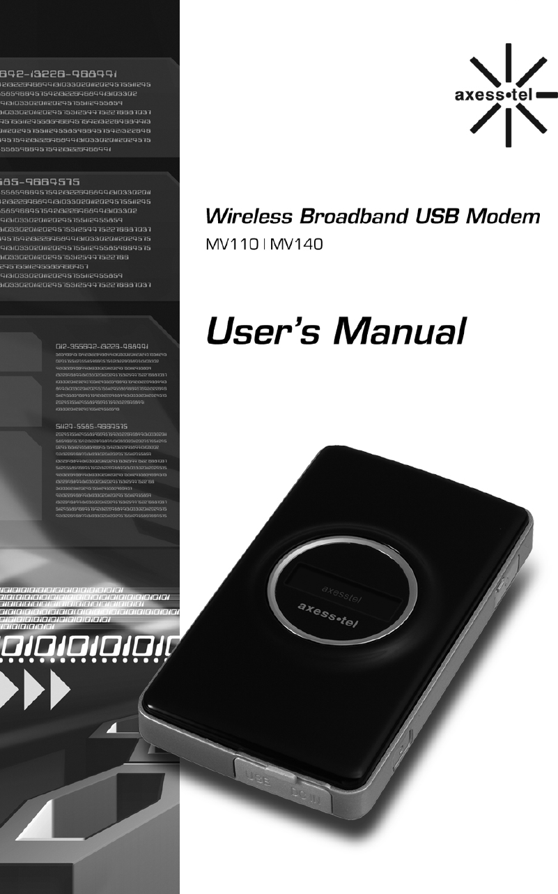
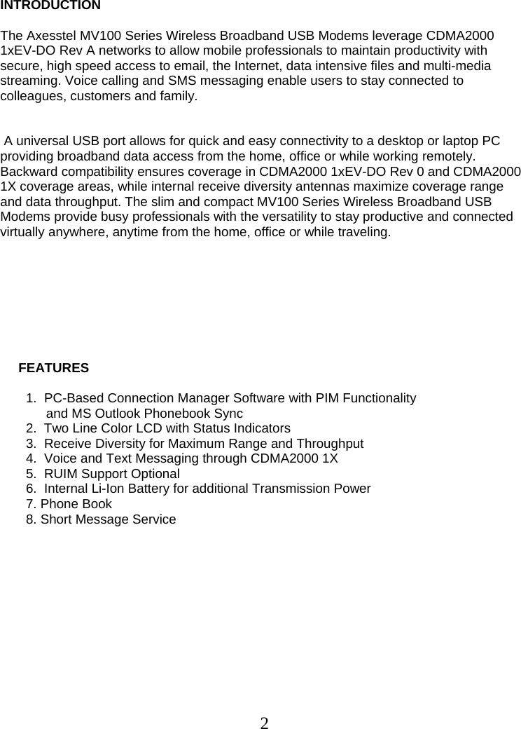
Axesstel MV140 Cellular/ PCS CDMA Modem User Manual MV100 Manual v0 2 Eng

Axesstel Inc Cellular/ PCS CDMA Modem MV100 Manual v0 2 Eng
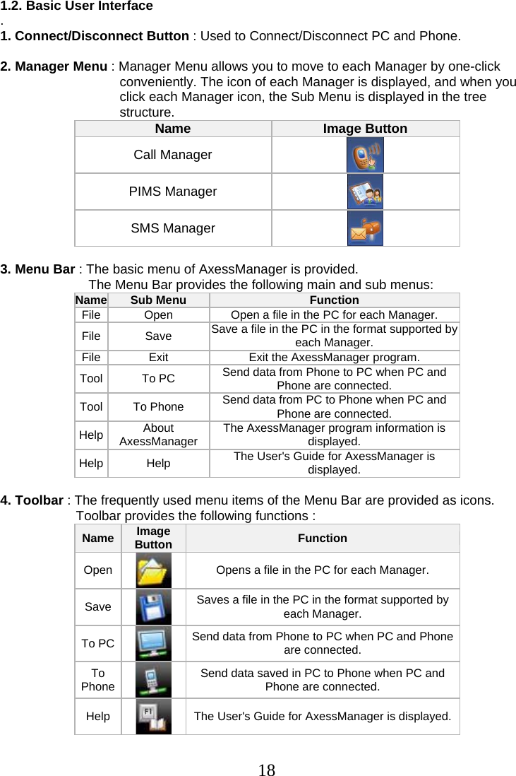
Contents

Users Manual

 1
 2 INTRODUCTION   The Axesstel MV100 Series Wireless Broadband USB Modems leverage CDMA2000 1xEV-DO Rev A networks to allow mobile professionals to maintain productivity with secure, high speed access to email, the Internet, data intensive files and multi-media streaming. Voice calling and SMS messaging enable users to stay connected to colleagues, customers and family.    A universal USB port allows for quick and easy connectivity to a desktop or laptop PC providing broadband data access from the home, office or while working remotely. Backward compatibility ensures coverage in CDMA2000 1xEV-DO Rev 0 and CDMA2000 1X coverage areas, while internal receive diversity antennas maximize coverage range and data throughput. The slim and compact MV100 Series Wireless Broadband USB Modems provide busy professionals with the versatility to stay productive and connected virtually anywhere, anytime from the home, office or while traveling.                   FEATURES                1.  PC-Based Connection Manager Software with PIM Functionality  and MS Outlook Phonebook Sync        2.  Two Line Color LCD with Status Indicators        3.  Receive Diversity for Maximum Range and Throughput        4.  Voice and Text Messaging through CDMA2000 1X        5.  RUIM Support Optional        6.  Internal Li-Ion Battery for additional Transmission Power         7. Phone Book         8. Short Message Service
 3   SAFETY PRECAUTIONS       1. Avoid placing the phone in a dusty location, or near a source of gas or fire.    2. Don't Shake, hit or drop the modem.    3. To clean the outside of the modem, use only a soft, dry cloth. The chemicals           in alcohol, benzene or acetone can damage the surface of the modem.     4. Do not twist or pull the Mini-B USB Cable.     5. Do not disassemble the modem.     6. Do NOT use the power adaptor if:          - The power cord is damaged.          - The phone has been dropped or damaged in any way.     7. Frequency and length of use can affect the life of the self-charging battery.         Contact your customer service if the battery is not operating properly.      8. Use only the designated self-charging battery. Dispose of exhausted batteries           properly. Never discard a battery in or near fire or flame.      9. Do not place the modem near water, for example, near a bathtub, sink, wet           basement, or swimming pool.       NOTE 1: The input and output voltages are indicated on the adapter.                    (Input: AC 100~240V, 50~60 Hz, Output: DC 5V, 2A)
 4   CHECKING THE PARTS      Once you have unpacked your phone, make sure that you have all the parts shown      below. If any piece is missing or broken, please call your customer service.        1. Main Unit                                                          2. Li-Ion Battery                                              4. Power Adaptor     3. USB Data Cable                                          5. User Manual
 5   SETTING UP YOUR MODEM                      Installing the modem            This modem operates by receiving DC power from the AXESSTEL power adaptor            that connects to an electrical outlet. The modem is equipped with a rechargeable            battery as a back up in case of an AC power failure.             Modem installation          1. Plug the smaller end of the adaptor into the modem as shown    and plug the other end into your laptop’s or PC’s USB port
 6 SETTING UP YOUR MODEM                      Installing the USB Driver and AxessManager             The entire process will take approximately 20 minutes to complete.                      Step 1 Once MV100 connect with your laptop, This window will appear. Click “Axesstel Manager Setup.exe” to install AxessManager.                 Step 2           Click Next to continue.
 7      Step 3      Click “Next” to continue.   Step 4 Click Finish to complete installation of AxessManager.
 8                Step 5 Click Axesstel_USB_Driver_Setup folder    Step 6 Click Setup.ext to install USB Driver.
 9 Step 7 Click Driver Install    Step 8   After finishing driver file copy, Modem will be change to Modem mode from CD ROM Mode.     Step 9  Axesstel USB Mode will be detected on your PC. Select Next to install USB Driver.
 10 Step 10 Select Continue Anyway.   Step 11 Select Finish to complete the process.
 11 Step 12 Axesstel Diagnostic Port will be detected on your PC. Select Next to install USB Driver.   Step 13 Select Continue Anyway.
 12 Step 14 Select Finish to complete the process. you can start to run AxessManager
 13  SETTING UP YOUR Modem            Service Status Check            Display in the Service Area           When the power cord is connected properly,                     all segments of the LCD window will turn on briefly.           The number of bars of signal strength indicator                                  (antenna icon) indicates the strength of service signal           of the area. The display will show the greeting with date           and time.           You can change the greeting. (See page 32)               Display in area with no service            When there is no service signal detected in your area,            no antenna bar appears. Contact your service provider            for the coverage area information.                                            Also check if the antenna is connected        AXESSTEL Fri, Feb 3 3:23pm AXESSTEL
 14 GETTING TO KNOW YOUR MODEM and AxessManager   1. Ear-mic: Insert Ear-mic to make a voice call.  2. Power button: Press to turn on / off the modem and hang up the call  3. Accessory Connector Part : Insert battery charger and Mini-B USB Cable  4. Main Display Window : Shows Status of the Modem.   <AxessManager> 1. Change Mode Button : Change to Manager mode from Data Connection Mode  2. Option Button : Change options of Modem and etc.  3. Connection Button : Connect via your operator’s network  4. Manager : PIMS, SMS and CALL Manager
 15  DISPLAY ICONS  Icons display on the screen to indicate what features you are using, e.g. signal strength, battery status and etc...                                           Indicate the strength of the signal. More bars indicates                                 stronger signal.                                   Indicates the level of battery power. The more bars, the                                 more power. When the battery is low, the icon blinks,                                 and an alert tone sounds.                                    Indicates that you are using CDMA 200 1X Network.                                     Indicates that you are using 1x EV-DO Network.                                     Indicates that a voice or data call is in progress                                     Indicates that you have text message message.           Indicates that you have voice mail message. AXESSTEL Fri, Feb 9  5:24P
 16                               To Start the AxessManager
 17 1. Getting Started When PC and modem is connected via the cable, AxessManager allows you to browse internet, modify modem configurations.  In addition, you can perform management tasks for phone numbers such as adding, modifying and deleting them, and you can write messages in your PC and send them to your modem.  AxessManager provides the following 5 menus :   Internet Connection : Internet Connection allows you to connect to internet  through local network provider.  PIMS Manager : You can manage phonebook in your PC.  Outlook contacts data can be imported/exported  SMS Manager : You can download the Inbox, Outbox, and Draft Box messages  in your phone to your PC and edit them, or upload newly created messages to your modem and send them to others  CALL Manager : You can make/receive a phone call. Call history can be managed  Options : You can manage modem settings   1.1. System Requirements  . The system requirements for using this software are summarized below:   (1) Recommended Specifications  CPU : Pentium III 550Mhz or higher, IBM PC-Compatible  RAM : 256MB or more  VGA : Video card with1024 I 768 resolution and 65536 or more colors  HDD : 200MB or more hard disk space  Others: CD-ROM Drive or DVD Drive  OS : Microsoft W  `indows 2000 or higher  . (2 )Minimum Specifications  CPU : Pentium II 300Mhz or higher, IBM PC-Compatible  RAM : 128MB or more  VGA : Video card with1024 I 768 resolution and 65536 or more colors HDD : 100MB or more hard disk space Others: CD-ROM Drive or DVD Drive OS : Microsoft Windows 2000 or higher
 181.2. Basic User Interface  . 1. Connect/Disconnect Button : Used to Connect/Disconnect PC and Phone.    2. Manager Menu : Manager Menu allows you to move to each Manager by one-click conveniently. The icon of each Manager is displayed, and when you click each Manager icon, the Sub Menu is displayed in the tree structure.  Name  Image Button Call Manager PIMS Manager SMS Manager     3. Menu Bar : The basic menu of AxessManager is provided.  The Menu Bar provides the following main and sub menus:  Name  Sub Menu  Function  File   Open   Open a file in the PC for each Manager.  File   Save   Save a file in the PC in the format supported by each Manager.  File   Exit   Exit the AxessManager program.  Tool   To PC   Send data from Phone to PC when PC and Phone are connected.  Tool   To Phone   Send data from PC to Phone when PC and Phone are connected.  Help   About AxessManager  The AxessManager program information is displayed.  Help   Help   The User's Guide for AxessManager is displayed.     4. Toolbar : The frequently used menu items of the Menu Bar are provided as icons.  Toolbar provides the following functions :  Name  Image Button Function  Open   Opens a file in the PC for each Manager.  Save  Saves a file in the PC in the format supported by each Manager.  To PC   Send data from Phone to PC when PC and Phone are connected.  To Phone  Send data saved in PC to Phone when PC and Phone are connected.  Help  The User's Guide for AxessManager is displayed.
 19   1.3. Connecting/Disconnecting Your Modem to/From the PC . Connecting  First, connect your PC with the modem using the cable supplied with the modem.  Insert the cable firmly to the modem until it clicks into place.  Click the icon on your desktop to run the AxessManager Program.  Click the Connect/Disconnect button . When the connection is successful, you can use the AxessManager program. All icons will be enabled  . Disconnecting  1) Click the Connect/Disconnect button after finishing your job.  The connection is discontinued and the active Connect/Disconnect button is changed to the disabled status. All icons will be disabled 2) To exit the program after finishing the job, click the button at top right of the program window.  3) Disconnect the cable from PC and modem.
 202. Internet Connect  Internet Connection System allows the PC to connect to the internet through network provider with Axesstel Modem.    1. Internet Connection Connect / Disconnect 1.1. Connect  Once the initial setup is complete, you can use your modem.  To make a communication connection using the modem, click the ‘E’ button on the main screen.  1.2. Disconnect  To disconnect from the communication connection, just click the ‘E’ button on the main screen.    2. Internet Connection Setup  Click the Options button on the main screen of the program to open the following dialog, where you can specify values for many items needed to set up your modem.  A short, functional description for each button on the Setup dialog is provided below. Button  Description  New   Allows you to add a new 'Connect Item'. Delete  Allows you to delete an existing 'Connect Item.'  Properties  Allows you to modify existing 'Connect Item' settings.  Modem   Allows you to view and select from a list of modems currently available for connection.    2.1. Add Connect Item  A description for each item is provided below.  (1) Country: Select a country for the connection via modem.  (2) Network Provider: Select a network provider for the country. (3) APN: Specify the APN value for the network provider.  (4) Connect Name: Enter the name to be displayed on the 'Connect Item' list.  (5) Phone: Specify the phone number to which modem will connect. The default is *99#.  (6) User Name: If required, enter the user ID for the network provider.  (7) Password: Enter the password for the user name. Select the 'Remember password'    checkbox if you want to save the password.  (8) Send QoS Setting: If you send the QoS value specified on the Advanced Settings     window during the connection, select the 'Send QoS Setting' checkbox.  2.2. Delete Connect Item  Select the 'Connect Item' you want to delete from the 'Connect Item' list in the Setup dialog, and click Delete. The selected 'Connect Item' will be deleted.   2.3. Modify Connect Item  Select the 'Connect Item' you want to modify from the 'Connect Item' list in the Setup dialog, and click Properties. The following dialog appears, allowing you to modify the settings. See  ‘Add Connect Item' for detailed descriptions about the settings.  2.4. View Modem List  Click Modem in the Setup dialog to open the following Windows default modem settings dialog, where you can change the modem.
 213. SMS Manager SMS Manager is composed of Inbox for keeping received messages, Outbox for saving messages that have been sent out, Draft Box for saving messages that have not yet sent out, and Saved Box for keeping important messages in the Inbox. You can directly send out messages from your PC to your phone, or download it from phone to PC for more convenient management  3.1. Inbox Manager To use Inbox Manager , click the Inbox icon  With Inbox Manager, you can reply to, forward, or delete selected messages.     1. Inbox List View (1) By default, Inbox List View shows all Inbox messages saved in the phone. (2) The details of the Inbox message selected from Inbox List View is displayed in the    Preview window at bottom. (3) You can delete the messages displayed in Inbox List View. (You cannot add.)     2. Preview Window & Reply/Forward(Send)(1) The details of the Inbox message selected from Inbox List View is displayed in the   Preview window at bottom. (2) When you click the Reply button in the Preview window, a new window pops up for   you to edit the message and send it to the sender. (3) When you click the Forward button in the Preview window, a new window pops up    for you to edit the message and send it to the another person.  (4) You can send a message to multiple persons. (5) Type in the phone number and click the search button to add to the recipients' list. (6) You can type in the number directly, or click the ok button to open the following   window  (7) You can search for existing phone numbers from the contact list.     3. Delete Inbox Data      Select the data to delete and press the Delete key on the keyboard.  To delete multiple data simultaneously, select them with your mouse while pressing down the Shift or Ctrl key and then press the Delete key. The selected Inbox data is deleted at once from the phone.  The deleted Inbox data cannot be restored.     4. To PC  The Inbox List View is updated with the Inbox messages currently saved in the phone.     5. To Saved Box  Select the data to protect, and press the Save button. The data will be saved in the  Saved box.
 22 3.2. Saved box Manager To use Saved Box Manager, click the Saved Box icon.  With Saved Box Manager, you can reply to, forward, or delete selected messages.    1. Saved Box List View (1) By default, Saved Box List View shows all Saved Box messages saved in the modem. (2) The details of the Saved Box message selected from Saved Box List View is displayed  in the Preview window at bottom. (3) You can delete the messages displayed in Saved Box List View. (You cannot add.)    2.  Preview Window & Reply/Forward(Send)(1) The details of the Saved Box message selected from Saved Box List View is displayed in the Preview window at bottom. (2) When you click the Reply button in the Preview window, a new window pops up for   you to edit the message and send it to the sender. (3) When you click the Forward button in the Preview window, a new window pops up    for you to edit the message and send it to the another person.  (4) You can send a message to multiple persons. (5) Type in the phone number and click the search button to add to the recipients' list. (6) You can type in the number directly, or click the ok button to open the following   window  (7) You can search for existing phone numbers from the contact list.    3. Delete Saved Box Data  Select the data to delete and press the Delete key on the keyboard. To delete multiple data simultaneously, select them with your mouse while pressing down the Shift or Ctrl key and then press the Delete key.  The selected Saved Box data is deleted at once from the modem.  The deleted Saved Box data cannot be restored.    4. To PC  The Saved Box List View is updated with the Saved Box messages currently saved in the modem.
 23  3.3. Outbox Manager  To use Outbox Manager, click the Outbox icon With Outbox Manager, you can forward, modify, or delete selected messages in Outbox.    1. Outbox List View  (1) By default, Outbox List View shows all Outbox messages saved in the modem. (2) The details of the Outbox message selected from Outbox List View is displayed in   the Preview window at bottom. (3) You can delete the data displayed in Outbox List View    2. Preview Window & Forward(Send)  (1) The details of the Outbox message selected from Outbox List View is displayed in  the Preview window at bottom. (2) To write a new message, click the Send button in the Preview window. A new   window pops up in which you can write a new message and send it to others. (3) When you click the Forward button in the Preview window, a new window pops up for you to edit the message and send it to the another person.  (4) You can send a message to multiple persons.  (5) Type in the phone number and click the search button to add to the recipients' list. (6) You can type in the number directly, or click the ok button to open the following   window  (7) You can search for existing phone numbers from the contact list.   3. Delete Outbox Data  Select the data to delete and press the Delete key on the keyboard. To delete multiple data simultaneously, select them with your mouse while pressing down the Shift or Ctrl key and then press the Delete key. The selected Outbox data is deleted at once from the modem  The deleted Outbox data cannot be restored    4. To PC  The Outbox List View is updated with the Outbox messages currently saved in the modem.
 24  3.4. Draft Box Manager  To use Draft Box Manager, click the Draft Box icon . With Draft Box Manager, you can forward, or delete selected messages in Draft Box.    1. Draft Box List View  (1) By default, Draft Box List View shows all Draft Box messages saved in the modem. (2) The details of the Draft Box message selected from Draft Box List View is displayed  in the Preview window at bottom. (3) You can delete the data displayed in Draft Box List View .    2. Preview Window & Forward(Send)  (1) The details of the Draft Box message selected from Draft Box List View is displayed  in the Preview window at bottom. (2) To write a new message, click the New button in the Preview window, or double click  an empty field in the Draft Box List. A new window pops up in which you can write a new message and send it to others.  (3) When you click the Forward button in the Preview window, a new window pops up for you to edit the message and send it to the another person. (4) You can send a message to multiple persons.  (5) Type in the phone number and click the search button to add to the recipients' list.  (6) You can type in the number directly, or click ok button to open the following window  (7) You can search for existing phone numbers from the contact list.    3. Delete Draft Box Data  Select the data to delete and press the Delete key on the keyboard.  To delete multiple data simultaneously, select them with your mouse while pressing down the Shift or Ctrl key and then press the Delete key.  The selected Draft Box data is deleted at once from the modem.  The deleted Draft Box data cannot be restored.    4. To PC  The Draft Box List View is updated with the Draft Box messages currently saved in the modem.    3.5. Send To send a new message, press Send button the Preview window.  A new window will pop up. There are 4 buttons in the Send window.   1. Send  Send the message directly to the recipients through the modem.   2. Send & Save Send the message directly to the recipients through the modem. The message is also saved in the Outbox in the modem   3. Save
 25Does not send the message. Message is saved in the Draftbox for later use.   4. Search  Search for phone number from the Phonebook.    4. PIMS Manager  By using PIMS Manager, you can upload contact data to your modem, or download it from modem to PC for more convenient management.   3-1 Contacts Manager By using the contacts, user can enter/change/erase the name, group, telephone numbers(mobile, home, office), Fax, E-Mail, Address. Also, user can check the number of SIM's and memories that can be registered, and here the number of possible registrations varies depending on the kinds of the connected modem.  Therefore, the entries in the contracts can be selectively registered to the SIM and Memories.    1. Upload(Modem -> PC)   After confirmation of successful connection with the modem,  select the ToolÆ ModemÆPC menu from the File menu on the top( Or, click the icon ).    2. Download(PC -> Modem)   After confirmation of successful connection with the modem,  select the ToolÆ PCÆModem menu from the File menu on the top (Or, click the icon ).    3. Adding Contacts  For addition of contacts, use the following rules.  (Data field length may vary in different modem models)  No  Items  Rule  1   Name   Number of name depends on SIM card/Modem specifications  2  Phone No For phone numbers, up to 20 digits can be entered Including codes such as ‘#’, ‘-‘, ‘*’ in case of saving to SIM. For phone numbers, up to 40 digits can be entered Including codes such as ‘#’, ‘-‘, ‘*’ in case of saving to Mem. Particularly, you can insert phone number, home, business, fax number in the case of Mem.  3   Group   When you select Mem, only can use.  4   Email   When you select Mem, only can use.(able to insert 50 digit)  5   Address  When you select Mem, only can use.(able to insert 50 digit)      Enter at least one digit in the Name and Phone Number.  For Phone Numbers, up to 20 digits can be entered including codes such as, '#', '-', '*'. For Names.  When you add data in SIM, the name have a restricted length by SIM and you can only add mobile number.
 26Select the SIM/Mem.  Select Group, E-mail, and input a desired text in Address (maximum 50 characters.)  You can selectively enter the items listed above except Name and Phone Number.  (at least one phone number should be input).   Press the Add button after entering necessary information to complete the addition.  To continue adding, repeat the above procedure.    4. Changing Contacts Data  (1) Select the name to be changed from the data list control screen.  (2) After changing and entering items of your choice, press the Edit button to complete   the changes.    5. Deleting Contacts  Select the name to be deleted from the Contacts Data List Control screen.  Also, multiple names can be selected and deleted at the same time just like the Windows. (Shift + Click for selection of block, Ctrl + Click for accumulating one at a time). Click the Delete button to delete the data on the chosen phone number.    6. Finding Phone Number  Enter the name you want to find, and then click the Search button.  When it is necessary to find the items continuously, press F3 key.    7. Arranging Contacts  (1) To arrange the Contacts, click the item on the Phone Number list.  (2) This will make the Contacts arranged with respect to the chosen item.    8. Making a Call  (1) To make an outgoing call, highlight the item on the Phone Number list, and click the Phone Call button.  (2) This will open the Phone Call Window.    3.2. CSV Conversion  This program not only reads and stores data files but also provides functions that convert the address book data to CSV files or read the existing CSV files and store them as current program data files.  In other words, the address book data of Outlook can be loaded in this program and, conversely, the data of this program can be stored in the address book of Outlook in CSV format.    1. Reading CSV Files  (1) Perform the following steps to read CSV files:  - Select Tool > Read CSV on the menu.  (2) A dialogue box is displayed as follows.  - When the above dialogue box is displayed, click 'Find File' button to select a CSV file stored in your PC.  (3)Then, a list of data read is displayed on Data List Window that shows the phonebook on PIMS Manager.
 272.  Writing CSV Files  (1) To store existing data as CSV files, perform the following steps.  - Select Tool> Write CSV on the menu.  (2) A dialogue box is displayed as shown below.  - When the above dialogue box is displayed, click 'Find File' button to specify the directory to store files in your PC and enter the name of the file to store.  - And under SCV Type, choose whether the CSV files to store are for Outlook.  - When you have chosen the directory and the CSV file names to store and the desired CSV type, click OK to implement CSV Write.  (3)You can open the CSV files stored as above not only with AxessManager but also with Outlook and view their contents.    3.3. vCard Conversion  This program also provides functions that convert the address book data to vCard files or read the existing vCard files and store them as current program data files. In other words, the address book data of AxessManager can be shared with any other programs that support vCard format.    1. Reading vCard Files  (1) Perform the following steps to read vCard files:  - Select Tool > Import vObject on the menu.  (2) A dialogue box is displayed as follows.  - When the above dialogue box is displayed, click 'Find File' button to select a vCard file (*.vcf) stored in your PC.  (3) Then, a list of data read is displayed on Data List Window that shows the phonebook on PIMS Manager.   2. Writing vCard Files  (1) To store existing data as vCard files, perform the following steps.  - Select Tool> Export vObject on the menu.  (2) A dialogue box is displayed as shown below.  - When the above dialogue box is displayed, click 'Find File' button to specify the   directory to store files in your PC and enter the name of the file to store.  - When you have chosen the directory and the vCard file names to store, click OK to   implement vCard Export.  (3) You can open the vCard files stored as above not only with AxessManager, but also with Outlook or other programs that support vCard 2.1 format.    3.4. Outlook Conversion  This program also provides functions to directly import/export address book data to/from the Outlook. Simply select Import/Export Outlook from the Tool menu, and follow the on-screen instructions.  Please note that only address book data from Outlook 2000 and above versions may be imported/exported. Outlook Express is not supported.
 28      5. Phone Call Phone Call window may be opened from the main window, or from the PIMS manager.   1.  Making a Call (1) Press number keypads (2) Type in numbers directly on the LCD box. (3) When typing/pressing numbers, press CLR button to erase last number entered, or END button to clear all numbers  (4) Press the Send button to make a call to the number displayed on the LCD box.  (5) Press END button to hang up the call.    2. Receiving a Call (1) When a call comes in, Phone Call window will pop up with CallerID displayed in the LCD box. (2) Press any key button, except the END key, to receive the incoming call. (3) Press END button to hang up the call.   3. Call History  (1) Press LIST button to open Call History Window.  (2) Select Incoming/Outgoing/Missed tabs to view each lists.  (3) Double clicking on the list will send phone number to the LCD box.  (4) Select an item from the list and press Delete button to delete the item.  (5) Select a tab, and press Delete All button to delete all items on that list.  (6) Press Reset button to delete all items on all the lists.    4. SMS  (1) Press SMS button to send a message to the number on the LCD box.  (2) SMS Window will be opened, and Send SMS Window will be opened  (if there is a number on the LCD box).  (3) Refer to SMS section to send a message.    5. PIMS  (1) Press PIMS button to look up a number in the address book.  (2) PIMS Window will be opened.  (3) Refer to PIMS section to manage phonebook data.
 29
 30                                  Miscellaneous  Specification
 31   SPECIFICATIONS  Frequency Range MV110  Rx: 462 ~ 468 MHz Tx: 452 ~ 458 MHz MV140 Rx: 869 ~ 894 MHz Tx: 824 ~ 849 MHz Rx: 1930 ~ 1989 MHz Tx: 1850 ~ 1909 MHz Channel Bandwidth  CDMA 1.25 MHz Stability of frequency  0.4 ppm External appearance (mm)  97 x 57 x 19.5 mm Weight  150 g (with battery) Sending output  maximum 0.23W E.R.P Temperature of operation Relative humidity  -20 ~ +50 degrees Celsius   5% ~ 90% Adapter  Input: AC 100~240V 50~60Hz  Output: DC 5V/2A Battery  760mAh, Li-ion
                                                      32SAR INFORMATION  THIS MODEL PHONE MEETS THE GOVERNMENT’S REQUIREMENTS FOR EXPOSURE TO RADIO WAVES.  Your wireless phone is a radio transmitter and receiver. It is designed and manufactured not to exceed the emission limits for exposure to radiofrequency (RF) energy set by the Federal Communications Commission of the U.S. Government. These limits are part of comprehensive guidelines and establish permitted levels of RF energy for the general population. The guidelines are based on standards that were developed by independent scientific organizations through periodic and thorough evaluation of scientific studies. The standards include a substantial safety margin designed to assure the safety of all persons, regardless of age and health. The exposure standard for wireless mobile phones employs a unit of measurement known as the Specific Absorption Rate, or SAR. The SAR limit set by the FCC is 1.6 W/kg. * Tests for SAR are conducted with the phone transmitting at its highest certified power level in all tested frequency bands. Although the SAR is determined at the highest certified power level, the actual SAR level of the phone while operating can be well below the maximum value. This is because the phone is designed to operate at multiple power levels so as to use only the power required to reach the network. In general, the closer you are to a wireless base station antenna, the lower the power output. Before a phone model is available for sale to the public, it must be tested and certified to the FCC that it does not exceed the limit established by the government adopted requirement for safe exposure. The tests are performed in positions and locations (e.g., at the ear and worn on the body) as required by the FCC for each model. The highest SAR value for this model phone when tested for use at the when worn on the body , as described in this user guide, is 0.997 W/Kg . (Body-worn measurements differ among phone models, depending upon available accessories and FCC requirements). While there may be differences between the SAR levels of various phones and at various positions, they all meet the government requirement for safe exposure. The FCC has granted an Equipment Authorization for this model phone with all reported SAR levels evaluated as in compliance with the FCC RF exposure guidelines. SAR information on this model phone is on file with the FCC and can
                                                       33be found under the Display Grant section of http://www.fcc.gov/ oet/fccid after searching on FCC ID: PH7MV140.  Additional information on Specific Absorption Rates (SAR) can be found on the Cellular Telecommunications Industry Asso-ciation (CTIA) web-site at http://www.wow-com.com. * In the United States and Canada, the SAR limit for mobile phones used by the public is 1.6 watts/kg (W/kg) averaged over one gram of tissue. The standard incorporates a sub-stantial margin of safety to give additional protection for the public and to account for any variations in measurements.    SAFETY INFORMATION FOR RF EXPOSURE  Body worm operation  This device was tested for typical body-worn operations with the back of the phone kept 25 mm. from the body. To maintain compliance with FCC RF exposure requirements, use only belt-clips, holsters or similar accessories that maintain a 25 mm. separation distance between the user’s body and the back of the phone, including the antenna. The use of belt-clips, holsters and similar accessories should not contain metallic components in its assembly. The use of accessories that do not satisfy these requirements may not comply with FCC RF exposure requirements, and should be avoided.
                                                    34 Safety Information  1 . SAFETY INFORMATION FOR FIXED WIRELESS TERMINALS .POTE NTIALLY EXPLOSIVE ATMOSPHERES Turn your phone OFF when in any area with a potentially explosive atmosphere and obey all signs and instructions. Sparks in such areas could cauls e an explosion or fire resulting in bodily injury or even death.  INTERFERENCE TO MEDICAL DIVICES Certain electronic equipment may be shielded against RF signal from you wireless phone. (pacemakers, Hearing Aids, and so on) Turn your phone OFF in health c are facilities when any regulations posted in these areas instruct you to do so. RF signals may affect improperly installed or inadequately shielded electronic system in motor vehicles.  .EXPOSURE TO RF ENERGY Use only the supplied or an approved replacement antenna. Do not touch the antenna unnecessarily when the phone is in use. Do not move the antenna close to, or couching any exposed part of the body when making a call.  FCC Compliance Information  This device complies with Part 15 of FCC Rules. Operation is subject to the following two conditions:  (1) This device may not cause harmful interference, and (2) This device must accept any interference received.    Including interference that may cause undesired operation.
                                                      35U.S.A. U.S.FEDERAL COMMUNICATIONS COMMISSION RADIO FREQUENCY INTERFERENCE STATEMENT  INFORMATION TO THE USER  NOTE : This equipment has been tested and found to comply with the limits for a Class B digital device pursuant to Part 15 of the FCC Rules. These limits are designed to provide reasonable protection against harmful Interference in a residential installation This equipment generates, uses, and can radiate radio frequency energy and, if Not installed and used in accordance with the instructions, may cause harmful Interference to radio communications. However, there is no guarantee that interference will not occur in a particular Installation. If this equipment does cause harmful interference to radio or television reception, which can be determined by turning the equipment off and on, the user is encouraged to try to correct the interference by one or more of the following measures: *- Reorient or relocate the receiving antenna. Increase the separation between the equipment and receiver.  *- Connect the equipment into an outlet of a circuit different from that to which the receiver is connected. *- Consult the dealer or an experienced radio/TV technician for assistance. Changes or modification not expressly approved by the party responsible for Compliance  could void the user’s authority to operate the equipment. Connecting of peripherals requires the use of grounded shielded signal cables.

Navigation menu