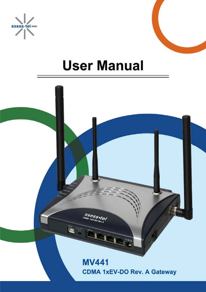
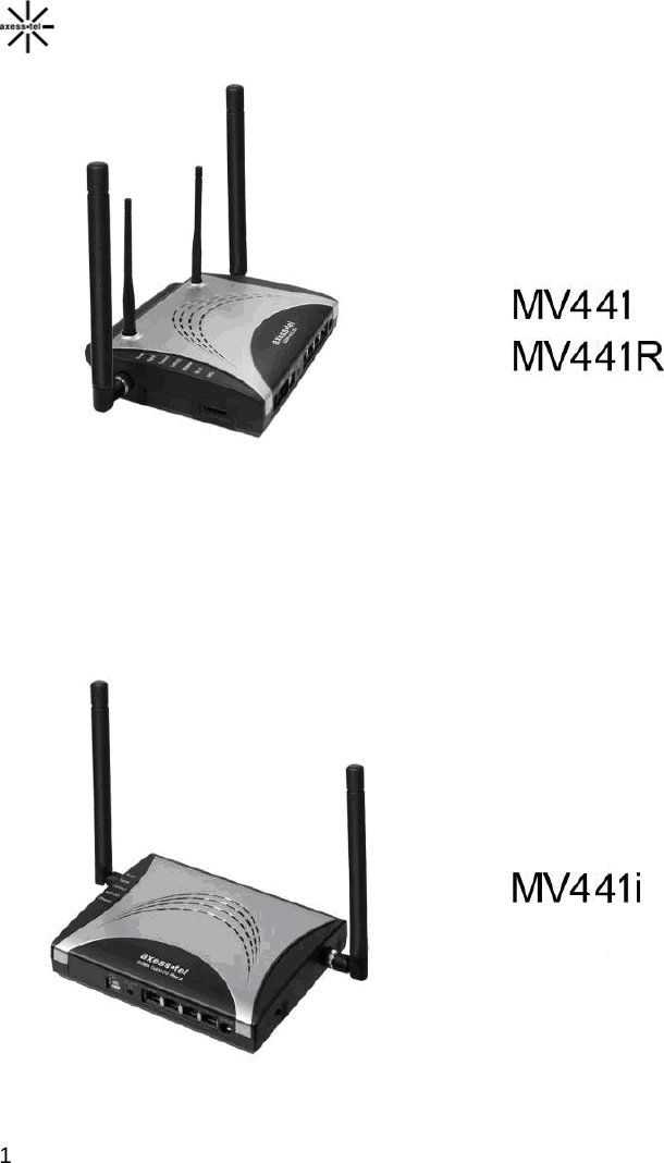
Axesstel MV441 CDMA 1xEV-DO Rev.A WiFi Gateway, Dual-Band 800/1900MHz User Manual MV441
Axesstel Inc CDMA 1xEV-DO Rev.A WiFi Gateway, Dual-Band 800/1900MHz MV441
UserManual.wiki
>
Axesstel
>
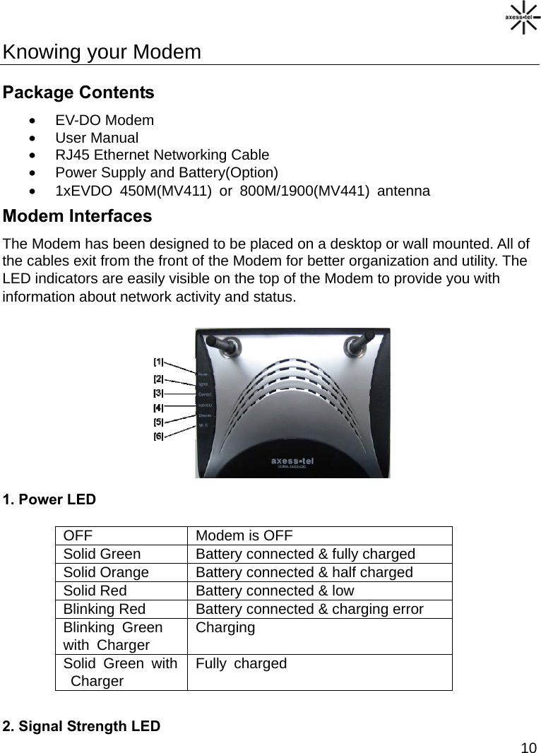
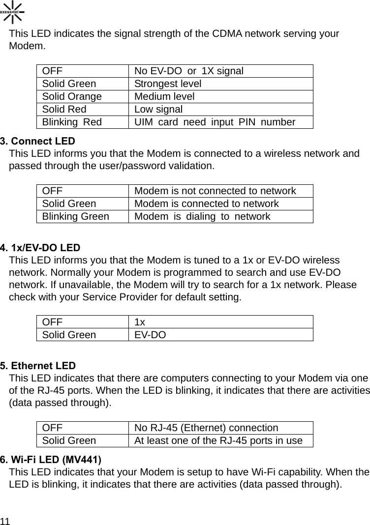
MV441 User Manual
User Manual
Navigation menu
Upload a User Manual
Namespaces
Wiki Guide
HTML
PDF
Info
Views
User Manual
Discussion / Help
Navigation
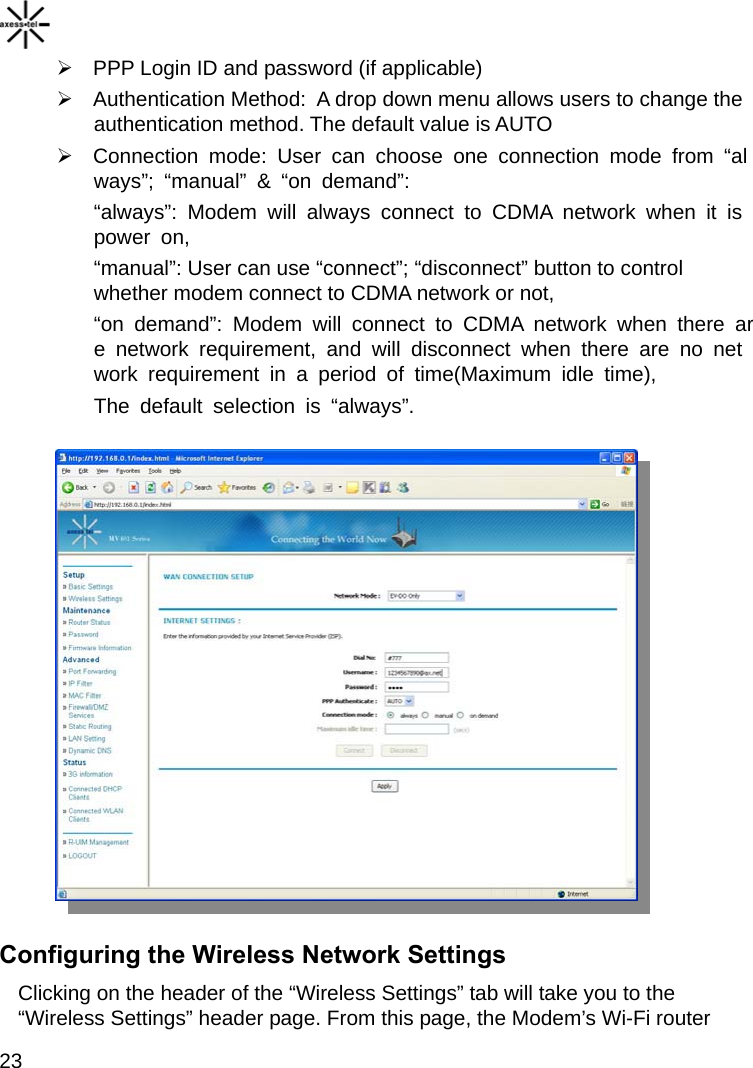
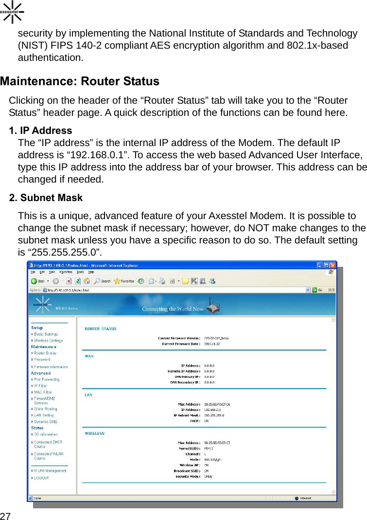
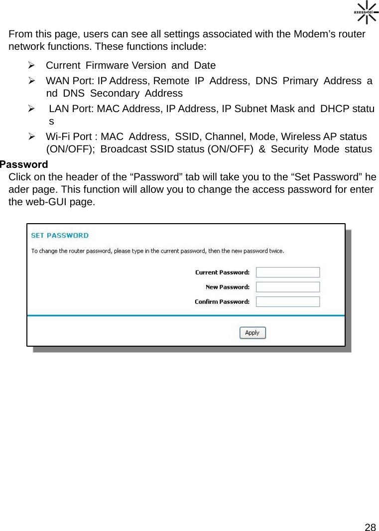
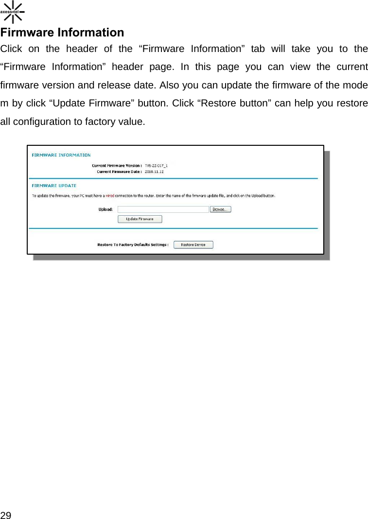
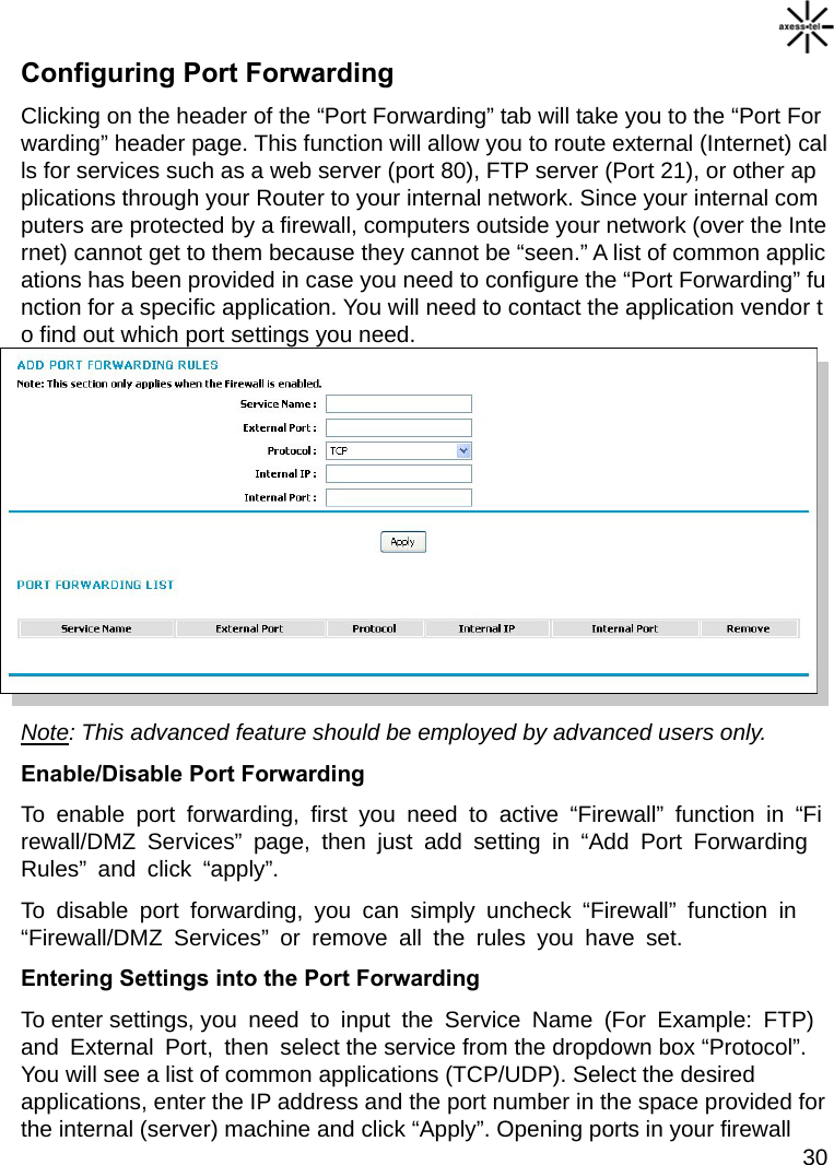
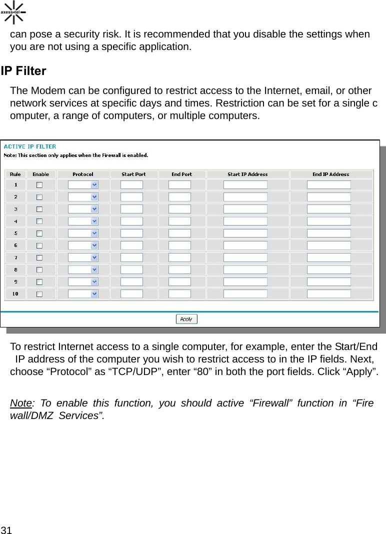
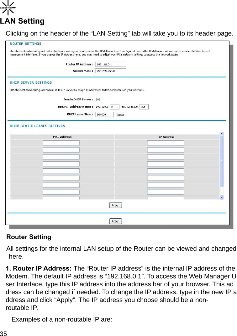
![22 1. Quick Navigation Links You can go directly to any of the Modem’s UI pages by clicking directly on these links. The links are divided into logical categories and grouped by tabs to make finding a particular setting easier to find. 2. Page Contents This part show the detailed information of the Navigation Link, This User Manual will sometimes refer to pages by name. For instance “Advanced > LAN IP Setup” refers to the “LAN IP Setup” page. Basic Settings Clicking on the header of the “Basic Settings” tab will take you to the “Basic Settings” header page. From this page, the Modem’s basic settings can be modified. These settings include: WAN Connection: A drop down menu allows users to change the providers. The default value is Hybrid Mode(EV-DO+1X) Dial No [1] [2]](https://usermanual.wiki/Axesstel/MV441/User-Guide-1482054-Page-23.png)