Axesstel MV441 CDMA 1xEV-DO Rev.A WiFi Gateway, Dual-Band 800/1900MHz User Manual MV441
Axesstel Inc CDMA 1xEV-DO Rev.A WiFi Gateway, Dual-Band 800/1900MHz MV441
Axesstel >
User Manual
1

2
Important Notice
Due to the nature of wireless communications, transmission and reception of data
can never be guaranteed. Data may be delayed, corrupted (i.e., have errors) or be
totally lost. Although significant delays or losses of data are rare when wireless
devices such as the Axesstel modem are used in a normal manner with a well-
constructed network, the Axesstel modem should not be used in situations where
failure to transmit or receive data could result in damage of any kind to the user or
any other party, including but not limited to personal injury, death, or loss of
property. Axesstel accepts no responsibility for damages of any kind resulting from
delays or errors in data transmitted or received using the Axesstel modem, or for
failure of the Axesstel modem to transmit or receive such data.
Safety and Hazards
Do not operate the Axesstel modem:
In areas where blasting is in progress
Where explosive atmospheres may be present
Near medical equipment
Near life support equipment, or any equipment that may be susceptible to
any form of radio interference. In such areas, the Axesstel modem MUST
BE POWERED OFF. The Axesstel modem can transmit signals that could
interfere with this equipment.
Do not operate the Axesstel modem in any aircraft, whether the aircraft is on the
ground or in flight. In aircraft, the Axesstel modem MUST BE POWERED OFF.
When operating, the Axesstel modem can transmit signals that could interfere
with various onboard systems.
Note: Some airlines may permit the use of cellular phones while the aircraft is on
the ground and the door is open. The Axesstel modem may be used at this time.
The driver or operator of any vehicle should not operate the Axesstel modem
while in control of a vehicle. Doing so will detract from the driver or operator’s
control and operation of that vehicle. In some states and provinces, operating
such communications devices while in control of a vehicle is an offence.

3
Limitation of Liability
The information in this manual is subject to change without notice and does not
represent a commitment on the part of Axesstel. AXESSTEL SPECIFICALLY
DISCLAIMS LIABILITY FOR ANY AND ALL DIRECT, INDIRECT, SPECIAL,
GENERAL, INCIDENTAL, CONSEQUENTIAL, PUNITIVE OR EXEMPLARY
DAMAGES INCLUDING, BUT NOT LIMITED TO, LOSS OF PROFITS OR
REVENUE OR ANTICIPATED PROFITS OR REVENUE ARISING OUT OF THE
USE OR INABILITY TO USE ANY AXESSTEL PRODUCT, EVEN IF AXESSTEL
HAS BEEN ADVISED OF THE POSSIBILITY OF SUCH DAMAGES OR THEY
ARE FORESEEABLE OR FOR CLAIMS BY ANY THIRD PARTY.
Notwithstanding the foregoing, in no event shall Axesstel aggregate liability arising
under or in connection with the Axesstel product, regardless of the number of
events, occurrences, or claims giving rise to liability, be in excess of the price paid
by the purchaser for the Axesstel product.

4
Table of Contents
1. Introduction ……………………………………….…...…………. 5
2. Product Overview …………………………….………...…...….. 7
3. Knowing your Modem ……………………….……..…………... 10
Package Contents ………………………………………………… 10
Modem Interfaces ………………………………………….……… 10
System Components ……………………………………………… 13
4. Connecting and Configuring your Modem …………………. 15
5. Web Manager User Interface …………….…………………..... 18
Basic Settings ………………………….……….…………………. 22
Configuring the Wireless Network Settings ………..…………... 23
Router Status ……………………………………….…….……….. 27
Password……………………………………………………………. 28
Firmware Information………………………………………………. 29
Configuring Port Forwarding ……………………….…………….. 30
IP Filter………………………………………………………………. 31
MAC Filter…………………………………………………………… 32
Firewall/DMZ Services……………………………………………... 33
Static Routing……………………………………………………….. 34
LAN Setting….………………………………………………………. 35
Dynamic DNS …………………………………………….….…….. 36
6. Troubleshooting …………………………………………………. 37
7. Technical Specification ………………………………………… 40
8. Glossary ………………………………………………………....... 41
Version:V3.4C(110402)

5
Introduction
Thank you for purchasing the Axesstel MV441EV-DO Modem (the Modem). This
user manual will help you setup, configure and outline best practices for
maximizing your wireless home network performance with the Modem. Please be
sure to read through this User Manual completely, and pay special attention to the
section entitled “Placement of your Modem for Optimal Performance” on page 2.
Placement of your Modem for Optimal Performance
Your wireless connection will be stronger the closer your computer is to your
Modem. Typical indoor operating range for Wi-Fi wireless devices is between 100
and 200 feet. For EV-DO operation, a line-of-sight with the radio base station is
preferred and yields the strongest signal strength.
In the same way, your wireless connection and performance will degrade
somewhat as the distance between your Modem and connected devices
increases, as well as between the Modem and the radio base station. This may or
may not be noticeable to you. As you move farther from your Modem, connection
speed may decrease. Factors that can weaken signals simply by getting in the
way of your network’s radio waves are metal appliances or obstructions, and walls.
Note: While some of the items listed below can affect network performance, they
will not prohibit your wireless network from functioning; if you are concerned that
your network is not operating at its maximum effectiveness, this checklist may
help.
1. Modem Placement
Place your Modem, the central connection point of your network, as close as
possible to windows or in rooms at the outer side of your house. If you also use
the Wi-Fi feature of the Modem, it should be placed near the center of your
wireless network devices.
To achieve the best wireless network coverage:
• Ensure that your Modem’s networking antennas are parallel to each other,
and are positioned vertically (toward the ceiling). If your Modem itself is
positioned vertically, point the antennas as much as possible in an
upward direction.

6
• In multistory homes, place the Modem on an upper floor.
• Try not to place the Modem near a cordless phone (MV400-series only).
2. Avoid Obstacles and Interference
Avoid placing your Modem near devices that may emit radio “noise,” such as
microwave ovens. Dense objects that can inhibit wireless communication include:
• Refrigerators
• Washers and/or dryers
• Metal cabinets
• Large aquariums
• Metallic-based, UV-tinted windows
If your wireless signal seems weak in some spots, try to move the Modem to
another location while observing the signal strength indicator. Since you may not
know the location of an EV-DO radio base station serving your Modem, try to call
your service provider and ask for the nearest base station of your home. Try
placing the Modem closest and unobstructed to that base station.

7
Product Overview
In minutes you will be able to connect your computers to the Internet, share your
Internet connection and network your computers. The following is a list of features
that make your new Axesstel EV-DO Modem an ideal solution for your home or
small office network. Implementation of these features depends on the particular
service provider and account features you have chosen.
Some features described in this manual may not be supported by your service
provider or may not be available with your network account. For details of the
services and accounts available, contact your service provider.
CDMA 3G services
The Modem operates over the CDMA 3G technology that provides a variety of
connectivity features, depending on your service provider and account:
1xEVDO Rev. A supports Internet connections with data rates up to 3.1
Mbps (downlink from the network) and 1.8 Mbps (uplink to the network).
Average data rates are roughly 600–1300 Kbps (downlink from the
network) and 300–400 Kbps (uplink to the network). Actual speed
depends on the network conditions.
1xEVDO Rev. 0 supports Internet connections with data rates up to 2.4
Mbps (downlink from the network) and 153 Kbps (uplink to the network).
Average data rates are roughly 400–700 Kbps (downlink from the
network) and 40–80 Kbps (uplink to the network). Actual speed depends
on the network conditions.
1X supports Internet connections with data rates up to 153 Kbps. Actual
speed depends on the network conditions.
Once the connection is established, you can open your browser and connect to
any web site that is accessible through the Internet, or access other Internet
services (such as email).
The connection is “active” when data transmission is occurring. If data
transmission stops for a period of time (determined by the network), the
connection becomes “dormant”; see page 26.

8
Plug-and-Play
Each Modem has been provisioned at the factory for use with a particular service
provider. This sets the Modem to use particular radio channels and enables
services specific for that provider. Although the Modem comes with drivers and
enabling software, you don’t have to install and use them if you simply want to
connect to the Internet, assuming that your Modem has been activated with the
network (The process of setting up your account is called activation. Activation
involves action by the service provider and configuration of the Modem.)
Once the Modem has been activated, simply connect your computer with the
Modem using the provided Ethernet (RJ-45) cable and you are ready to use the
Internet.
Works with Both PCs and Mac® Computers
The Modem supports a variety of networking environments including Mac OS®
9.x, X v10.x, AppleTalk®, Linux®, Windows® 98, Me, NT®, 2000, and XP, and
others. All that is needed is an Internet browser and a network adapter that
supports TCP/IP (the standard language of the Internet).
Top-View LED Display
Lighted LEDs on the top of the Modem indicate which functions are in operation.
You’ll know at-a-glance whether your Modem is in EV-DO or 1X mode, connected
to the Internet, and in Wi-Fi or Ethernet operation. This feature eliminates the
need for advanced software and status-monitoring procedures.
Web-Based Advanced User Interface
You can set up the Modem’s advanced functions easily through web browser,
without having to install additional software onto the computer. There are no disks
to install or keep track of and, best of all, you can make changes and perform
setup functions from any computer on the network quickly and easily.
NAT IP Address Sharing
Your Modem employs Network Address Translation (NAT) to share the single IP
address assigned to you by your Internet Service Provider while saving the cost of
adding IP addresses to your Internet service account.
Integrated 10/100 4-Port Switch
The Modem has a built-in, 4-port network switch to allow your wired computers to
share printers, data and MP3 files, digital photos, and much more. The switch
features automatic detection so it will adjust to the speed of connected devices.

9
The switch will transfer data between computers and the Internet simultaneously
without interrupting or consuming resources.
Built-In Dynamic Host Configuration Protocol (DHCP)
Built-In Dynamic Host Configuration Protocol (DHCP) on-board makes for the
easiest possible connection of a network. The DHCP server will assign IP
addresses to each computer automatically so there is no need for a complicated
networking setup.
Integrated 802.11n Wireless Access Point
802.11n is an exciting new wireless technology that achieves data rates up to
600Mbps, nearly twelve times faster than 802.11g.
MAC Address Filtering
For added security, you can set up a list of MAC addresses (unique client
identifiers) that are allowed access to your network. Every computer has its own
MAC address. Simply enter these MAC addresses into a list using the Web-Based
Advanced User Interface and you can control access to your network.
10
Knowing your Modem
Package Contents
• EV-DO Modem
• User Manual
• RJ45 Ethernet Networking Cable
• Power Supply and Battery(Option)
• 1xEVDO 450M(MV411) or 800M/1900(MV441) antenna
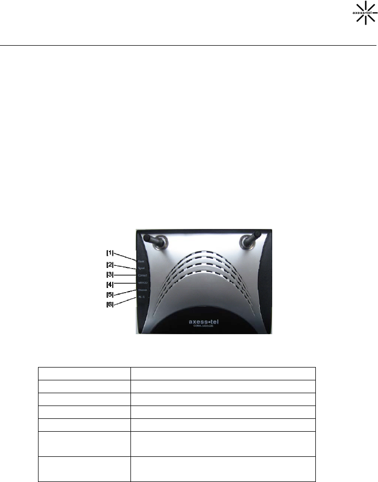
Modem Interfaces
The Modem has been designed to be placed on a desktop or wall mounted. All of
the cables exit from the front of the Modem for better organization and utility. The
LED indicators are easily visible on the top of the Modem to provide you with
information about network activity and status.
1. Power LED
OFF Modem is OFF
Solid Green Battery connected & fully charged
Solid Orange Battery connected & half charged
Solid Red Battery connected & low
Blinking Red Battery connected & charging error
Blinking Green
with Charger Charging
Solid Green with
Charger Fully charged
2. Signal Strength LED

11
This LED indicates the signal strength of the CDMA network serving your
Modem.
OFF No EV-DO or 1X signal
Solid Green Strongest level
Solid Orange Medium level
Solid Red Low signal
Blinking Red UIM card need input PIN number
3. Connect LED
This LED informs you that the Modem is connected to a wireless network and
passed through the user/password validation.
OFF Modem is not connected to network
Solid Green Modem is connected to network
Blinking Green Modem is dialing to network
4. 1x/EV-DO LED
This LED informs you that the Modem is tuned to a 1x or EV-DO wireless
network. Normally your Modem is programmed to search and use EV-DO
network. If unavailable, the Modem will try to search for a 1x network. Please
check with your Service Provider for default setting.
OFF 1x
Solid Green EV-DO
5. Ethernet LED
This LED indicates that there are computers connecting to your Modem via one
of the RJ-45 ports. When the LED is blinking, it indicates that there are activities
(data passed through).
OFF No RJ-45 (Ethernet) connection
Solid Green At least one of the RJ-45 ports in use
6. Wi-Fi LED (MV441)
This LED indicates that your Modem is setup to have Wi-Fi capability. When the
LED is blinking, it indicates that there are activities (data passed through).
12
OFF No Wi-Fi
Solid Green Wi-Fi network within Modem is activated
Blinking Green Active data passed through Wi-Fi
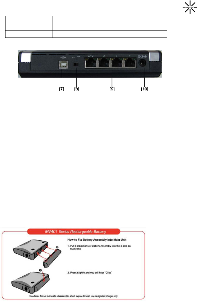
7. USB Connection to Computers
Connect your wired (non-wireless) computer to this port using the supplied USB
cable.
8. USB/RJ-45 Switch
This switch allows your Modem to connect with your computer via either USB
port or RJ-45 ports. USB port is just for debug, if you want to access to internet,
the switch must be at RJ-45 port side.
9. Connections to Computers (Wired Computer Ports)
Connect your wired (non-wireless) computers to these ports. These ports are
RJ45, 10/100 auto-negotiation, auto up-linking ports for standard UTP category
5 or 6 Ethernet cable. The ports are labeled 1 through 4.
10. Power Jack
Connect the included 12V DC power supply to this jack.
11. Rechargeable Battery (Optional)

13
System components
Your Modem is just one part of a system designed to provide you with a wide
range of communication features. Every component of the system is needed to
enable these capabilities.
Your host computing device
Your notebook or PC hosts the Modem and runs the communication software:
your web browser or email application and Connection Manager—the Modem
enabling software.
You may also have other software on your computer that can be used wirelessly
with the Modem, such as: file transfer applications (FTP), chat or instant
messaging, a VPN (Virtual Private Network) client, client software for a corporate
server application.
The Modem
The Modem provides your computer with a connection to the CDMA wireless
network. Every CDMA network operates on one of three radio frequency bands
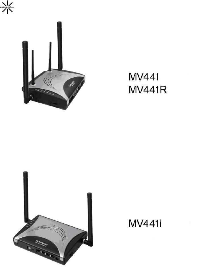
(450MHz, 800MHz and 1900MHz). The Modem is available in two configurations:
MV411 single-band 450MHz Modem, MV441 dual-band 800/1900MHz Modem.
A CDMA service provider account
Companies that operate CDMA networks and provide access to these networks
are called service providers. To use the Modem, you must have an account with a
CDMA service provider.
Each service provider has its own pricing options. There may be flat rate accounts,
which provide you a maximum number of minutes of network usage for a fixed
monthly fee. There may be accounts for which you are charged for network usage
by the minute or by the amount of data transmitted.
Your account may include a variety of other services such as SMS messaging.
Each Modem has been provisioned at the factory for use with a particular service
provider. This sets the Modem to use particular radio channels and enables
services specific for that provider.
The process of setting up your account is called activation. Activation involves
action by the service provider and configuration of the Modem.

14
The CDMA wireless network
This is the worldwide infrastructure providing the radio coverage that allows you to
stay connected. Made up of radio towers and a variety of network switches,
routers, and servers, the network is an interconnection of many service providers.
Note: More information about CDMA networks is available on the CDMA
Development Group web site, www.cdg.org.
There are CDMA networks that operate in the frequency bands supported by the
Modem throughout North America and parts of Latin America, Asia, and New
Zealand. However, each service provider operates a network that covers a limited
geographical area within the overall CDMA coverage area.
Note: Some service providers have coverage maps on their web sites.
15
Connecting and Configuring your Modem
Each Modem has been provisioned at the factory for use with a particular service
provider. This sets the Modem to use particular radio channels and enables
services specific for that provider.
MV441 and MV441i: All drivers and software have been installed into your
modem, you don’t have to install anything if you simply want to connect to the
Internet through the Ethernet (RJ-45) ports, assuming that your Modem has been
activated with the network. Simply connect your computer with the Modem using
the provided Ethernet (RJ-45) cable and you are ready to use the Internet.
Step 1 │ Set up the Hardware
1.1. Make sure your Modem is not connected to any power source and all the
LED are OFF.
1.2 Locate the CAT-5 Ethernet cable that is included with your Modem. Plug
one end of this cable into ANY one of the Ethernet ports on your Modem.
Plug the other end of the cable into the networking port on your computer.
1.3 Locate the power supply that is included with your Modem. Plug the power
supply’s small connector into the power port on the Modem. Plug the power
supply into an empty power outlet.
1.4 Switch on the Modem. Look at the Power LED on top of the Modem and
make sure the lights are ON.
1.5 Wait for a few seconds for the Modem to search for service network. Once
the Modem finds a suitable network, observe the Signal LED turns to Red,
Orange or Green depending on the strength of acquired signal. Refer to the
Signal Strength LED description for more details.
Step 2 │ Preparing your PC
The Modem’s Ethernet is configured with DHCP by default. This means that IP ad
dress of your PC is automatically assigned by the Modem. Make sure that your P
C has the correct TCP/IP setting for its "Local Area Connection" by following the st
eps below.
16
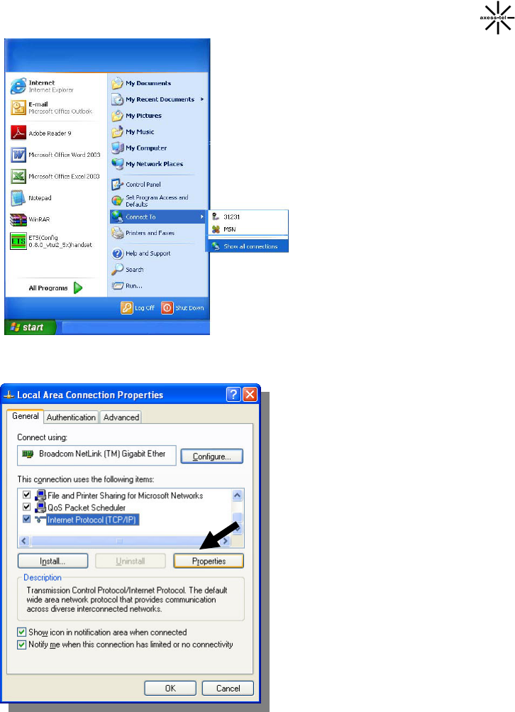
2.1 Click "Start", select "Connect
To" and scroll down to "Show all
connections" and left click it.
2.2 Right click "Local Area
Connection" scroll down to
"Properties" and left click it
2.3 Select the “Internet Protocol
(TCP/IP)”. Press the “Properties”
button.
If there is no TCP/IP line listed, you
will need to install TCP/IP first.
17
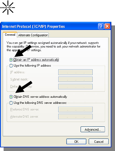
2.4 Check “Obtain an IP address
automatically”
2.5 Check “Obtain DNS Server
address automatically”
2.6 Click Ok to exit Properties
2.7 If asked to re-start the PC, click
“YES”.

18
Web Manager User Interface
The Web Manager User Interface is a web-based tool that you can use to set
up the Modem if you don’t want to use the default setting of Web page. You can
also use it to manage advanced functions of the Modem. From the User Interface,
you can perform the following tasks:
• View the Modem’s current settings and status
• Configure the EVDO network mode, amend the Dialer number, PPP
username, PPP password and authentication mode
• Configure the wireless settings such as SSID, security mode, enable
or disable wireless network, hide wireless network to satisfy different
requirement(not applicable to MV400i-series)
• Configure the Modem's router function to connect to your Service
Provider with the settings that they provided you
• Change the current network settings such as the Internal IP address, the
IP address pool, DHCP settings, and more
• Set the Modem’s port forwarding
• Enable or disable the Modem’s firewall, enable DMZ function to let you
set a single computer on your network outside of the router
• Set up security features such as client restrictions, MAC address filtering
• Enable the Firewall and DMZ feature for a single computer on your
network
• Change the Modem’s internal password
• Configure Dynamic DNS function
• View the Modem’s current 3G information, connected DHCP clients and
WLAN clients.
• Reset the Modem’s default settings
• Update the Modem’s firmware
Step 1 │ Access Network Setup
Follow below steps to configure your Modem’s Ethernet connection.
19
1. Connect the PC to your Modem using the CAT-5 Ethernet cable. Use ANY one
of the Ethernet ports on your Modem.
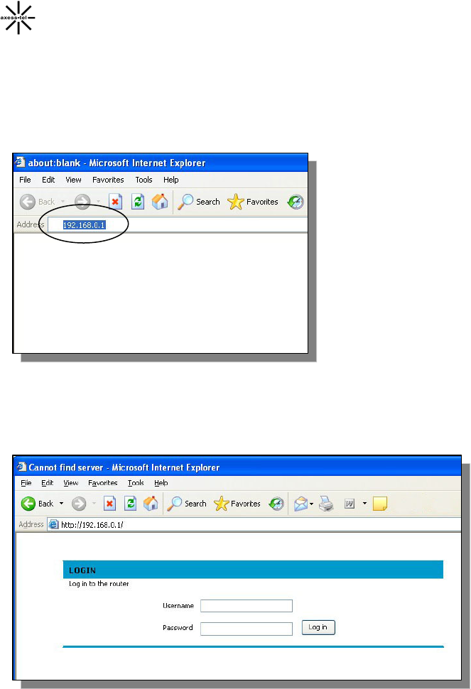
2. Power on the device, waiting for about 90 seconds until the device finish
initializing.
3. Open your Web browser and enter 192.168.0.1 in the address bar
2. A new webpage will appear. When prompt for User name and password, enter
the following user id and password.
User Name: admin
Password: admin
* If you have changed the user name and the password, enter the new user name
20
and password.
Note: This user name and password are only for the Web Manager access.
Changing these settings does not change Dial Connection user profile name and
password.
After entering the correct user name and password then click Login button, the
web browser will change to “Basic Setting” page. See the following picture:
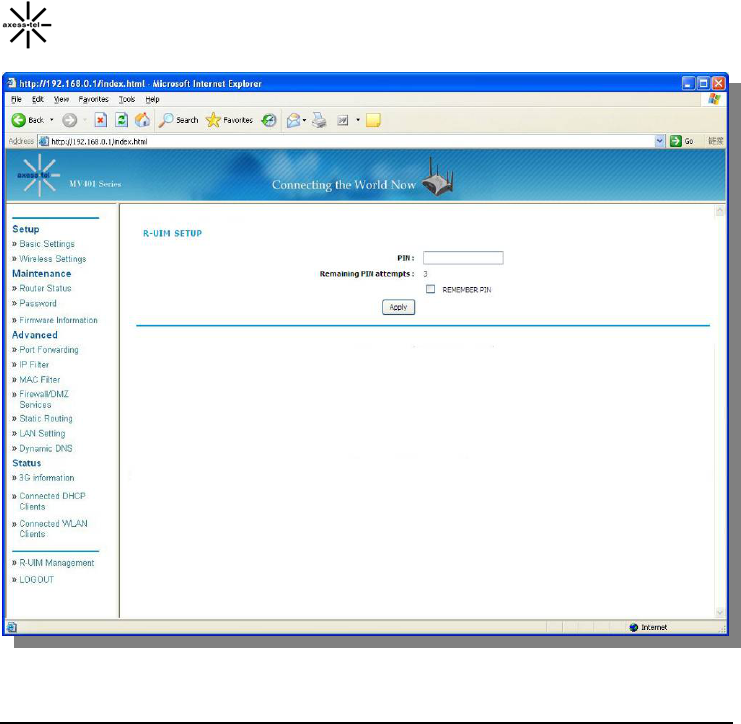
Note: If the Modem is UIM card mode and UIM card need PIN number, when you
first enter this page, the page will be different, it is shown as the following picture
in the next page, at the same time the signal LED will be red blinking to tell you
need input the PIN number. For detailed information, please refer next chapter.
21
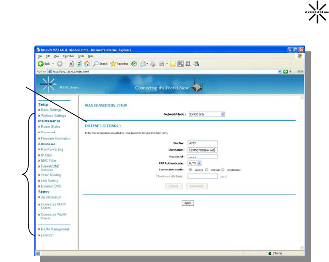
Step 2 │Navigate web-based UI
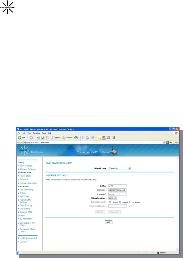
2.1 The Basic Setting page is the first page you will see when you access the
web based Advanced User Interface (UI). The basic setting page shows you
a quick view of the Modem’s login setting. All advanced setup pages can be
reached from this page.
22
1. Quick Navigation Links
You can go directly to any of the Modem’s UI pages by clicking directly
on these links. The links are divided into logical categories and grouped
by tabs to make finding a particular setting easier to find.
2. Page Contents
This part show the detailed information of the Navigation Link, This
User Manual will sometimes refer to pages by name. For instance
“Advanced > LAN IP Setup” refers to the “LAN IP Setup” page.
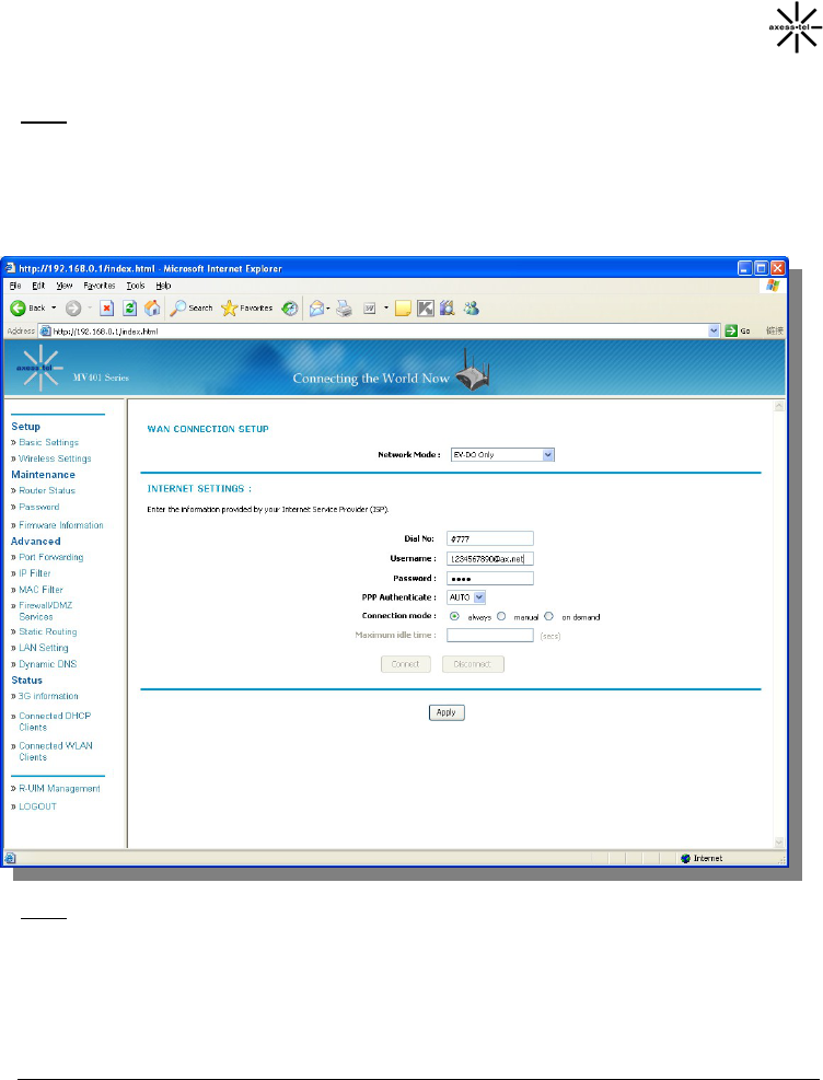
Basic Settings
Clicking on the header of the “Basic Settings” tab will take you to the “Basic
Settings” header page. From this page, the Modem’s basic settings can be
modified. These settings include:
WAN Connection: A drop down menu allows users to change the
providers. The default value is Hybrid Mode(EV-DO+1X)
Dial No
[1]
[2]
23
PPP Login ID and password (if applicable)
Authentication Method: A drop down menu allows users to change the
authentication method. The default value is AUTO
Connection mode: User can choose one connection mode from “al
ways”; “manual” & “on demand”:
“always”: Modem will always connect to CDMA network when it is
power on,
“manual”: User can use “connect”; “disconnect” button to control
whether modem connect to CDMA network or not,
“on demand”: Modem will connect to CDMA network when there ar
e network requirement, and will disconnect when there are no net
work requirement in a period of time(Maximum idle time),
The default selection is “always”.
Configuring the Wireless Network Settings
Clicking on the header of the “Wireless Settings” tab will take you to the
“Wireless Settings” header page. From this page, the Modem’s Wi-Fi router
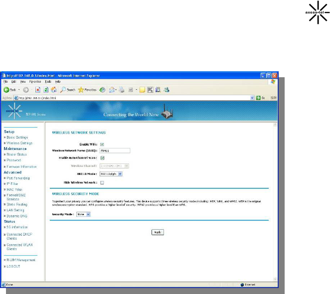
24
wireless radio can be enabled or disabled (the default setting is enabled). There
are options that allow you to make changes to the Wi-Fi wireless network
settings.
Changing the Wireless Network Name (SSID)
To identify your wireless network, a name called the SSID (Service Set
Identifier) is used. The default SSID of the Modem is “AxessMV441”. You can
change this to anything you want to or you can leave it unchanged. If there are
other wireless networks operating in your area, you will want to make sure that
your SSID is unique (does not match that of another wireless network in the
area). To change the SSID, type in the SSID that you want to use in the “SSID”
field and click “Apply”. The change is immediate. If you make a change to the
SSID, your wireless-equipped computers may also need to be reconfigured to
connect to your new network name. Refer to the documentation of your wireless
network adapter for information on making this change.
Changing the Wireless Channel
There are a number of operating channels you can choose from. In the United
States and Australia, there are 11 channels. In the United Kingdom and most of
Europe, there are 13 channels. In a small number of other countries, there are
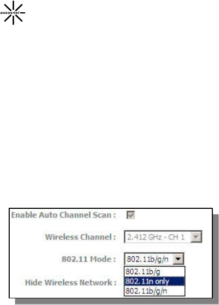
25
other channel requirements. Your Modem is configured to operate on the proper
channels for the country you reside in. If you don’t know which channel does
your country use, you can select “Enable Auto Channel Scan”, let the router
help you automatically select channel, this function is default to be active.
The channel can be changed if needed. If there are other wireless networks
operating in your area, your network should be set to operate on a channel that
is different than the other wireless networks. For best performance, use a
channel that is at least five channels away from the other wireless network. For
instance, if another network is operating on channel 11, then set your network to
channel 6 or below. To change the channel, select the channel from the drop-
down list. Click “Apply”. The change is immediate.
Using the Wireless Mode Switch
Your Modem can operate in three different wireless modes: “b and g”, “n only”,
and “b,g and n”.
b,g and n Mode
In this mode, the Modem is
compatible with 802.11b,g and
n wireless clients
simultaneously. This is the
factory default mode and
ensures successful operation
with all Wi-Fi compatible
devices. If you have a mix of 802.11b,g and n clients in your network, we
recommend setting the Modem to 802.11b,g and n mode. This setting should
only be changed if you have a specific reason to do so.
b and g Mode
b and g mode works with 802.11b,g clients only, not 802.11n clients. This
mode is recommended only if your clients do not support 802.11n mode.To
switch modes, select the desired mode from the “Wireless Mode” drop-down
box. Then, click “Apply Changes”.
n only Mode
n only mode works with 802.11n clients only. This mode is recommended only
if you want to prevent 802.11b and g clients from accessing your network.
When to use b and g Mode
In some cases, older 802.11b,g clients may not be compatible with 802.11n
wireless. These adapters tend to be of inferior design and may use older drivers
26
or technology. Switching to this mode can solve problems that sometimes occur
with these clients. If you suspect that you are using a client adapter that falls
into this category of adapters, first check with the adapter vendor to see if there
is a driver update. If there is no driver update available, switching to b and g
mode may fix your problem. Please note that switching to n only mode will
decrease 802.11b and g performance.
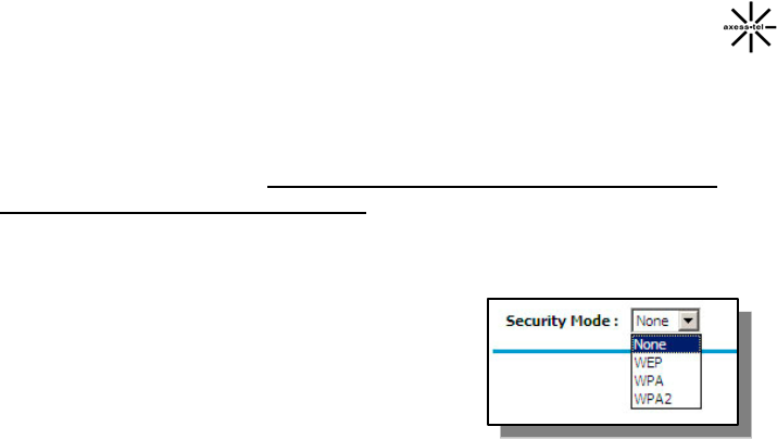
Securing your Wi-Fi® Network
Here are a few different ways you can maximize
the security of your wireless network and protect
your data from prying eyes and ears. This
section is intended for the home, home office,
and small office user. At the time of this User
Manual’s publication, there are three encryption
methods available.
WEP (Wired Equivalent Privacy)
WEP (Wired Equivalent Privacy) is a common protocol that adds security to
all Wi-Fi compliant wireless products. WEP was designed to give wireless
networks the equivalent level of privacy protection as a comparable wired
network.
WPA (Wi-Fi Protected Access)
WPA (Wi-Fi Protected Access) is a new Wi-Fi standard that was designed to
improve upon the security features of WEP. To use WPA security, the drivers
and software of your wireless equipment must be upgraded to support WPA.
These updates will be found on the wireless vendor’s website.
WPA-PSK (no server) uses what is known as a pre-shared key as the network
key. A network key is basically a password that is between eight and 63
characters long. It can be a combination of letters, numbers, or characters.
Each client uses the same network key to access the network. Typically, this
is the mode that will be used in a home environment.
WPA2 (Wi-Fi Protected Access 2)
Short for Wi-Fi Protected Access 2, the follow on security method to WPA for
wireless networks that provides stronger data protection and network access
control. It provides enterprise and consumer Wi-Fi users with a high level of
assurance that only authorized users can access their wireless networks.
Based on the IEEE 802.11i standard, WPA2 provides government grade
27
security by implementing the National Institute of Standards and Technology
(NIST) FIPS 140-2 compliant AES encryption algorithm and 802.1x-based
authentication.
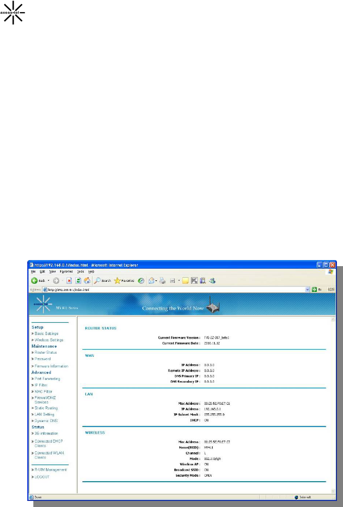
Maintenance: Router Status
Clicking on the header of the “Router Status” tab will take you to the “Router
Status” header page. A quick description of the functions can be found here.
1. IP Address
The “IP address” is the internal IP address of the Modem. The default IP
address is “192.168.0.1”. To access the web based Advanced User Interface,
type this IP address into the address bar of your browser. This address can be
changed if needed.
2. Subnet Mask
This is a unique, advanced feature of your Axesstel Modem. It is possible to
change the subnet mask if necessary; however, do NOT make changes to the
subnet mask unless you have a specific reason to do so. The default setting
is “255.255.255.0”.
28
From this page, users can see all settings associated with the Modem’s router
network functions. These functions include:
Current Firmware Version and Date
WAN Port: IP Address, Remote IP Address, DNS Primary Address a
nd DNS Secondary Address
LAN Port: MAC Address, IP Address, IP Subnet Mask and DHCP statu
s
Wi-Fi Port : MAC Address, SSID, Channel, Mode, Wireless AP status
(ON/OFF); Broadcast SSID status (ON/OFF) & Security Mode status
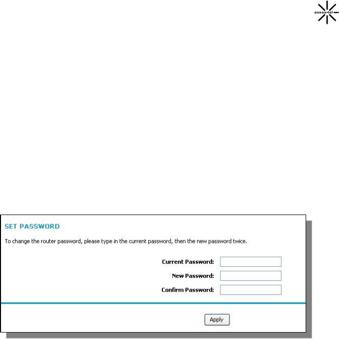
Password
Click on the header of the “Password” tab will take you to the “Set Password” he
ader page. This function will allow you to change the access password for enter
the web-GUI page.
29
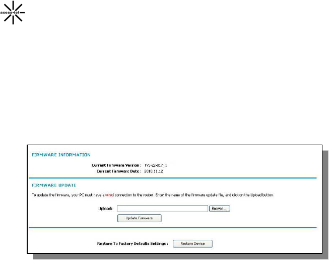
Firmware Information
Click on the header of the “Firmware Information” tab will take you to the
“Firmware Information” header page. In this page you can view the current
firmware version and release date. Also you can update the firmware of the mode
m by click “Update Firmware” button. Click “Restore button” can help you restore
all configuration to factory value.
30
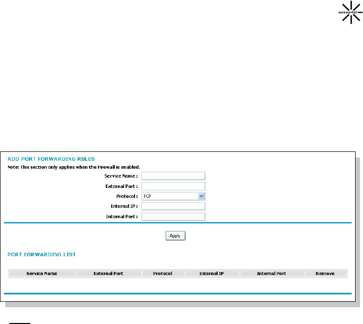
Configuring Port Forwarding
Clicking on the header of the “Port Forwarding” tab will take you to the “Port For
warding” header page. This function will allow you to route external (Internet) cal
ls for services such as a web server (port 80), FTP server (Port 21), or other ap
plications through your Router to your internal network. Since your internal com
puters are protected by a firewall, computers outside your network (over the Inte
rnet) cannot get to them because they cannot be “seen.” A list of common applic
ations has been provided in case you need to configure the “Port Forwarding” fu
nction for a specific application. You will need to contact the application vendor t
o find out which port settings you need.
Note: This advanced feature should be employed by advanced users only.
Enable/Disable Port Forwarding
To enable port forwarding, first you need to active “Firewall” function in “Fi
rewall/DMZ Services” page, then just add setting in “Add Port Forwarding
Rules” and click “apply”.
To disable port forwarding, you can simply uncheck “Firewall” function in
“Firewall/DMZ Services” or remove all the rules you have set.
Entering Settings into the Port Forwarding
To enter settings, you need to input the Service Name (For Example: FTP)
and External Port, then select the service from the dropdown box “Protocol”.
You will see a list of common applications (TCP/UDP). Select the desired
applications, enter the IP address and the port number in the space provided for
the internal (server) machine and click “Apply”. Opening ports in your firewall
31
can pose a security risk. It is recommended that you disable the settings when
you are not using a specific application.
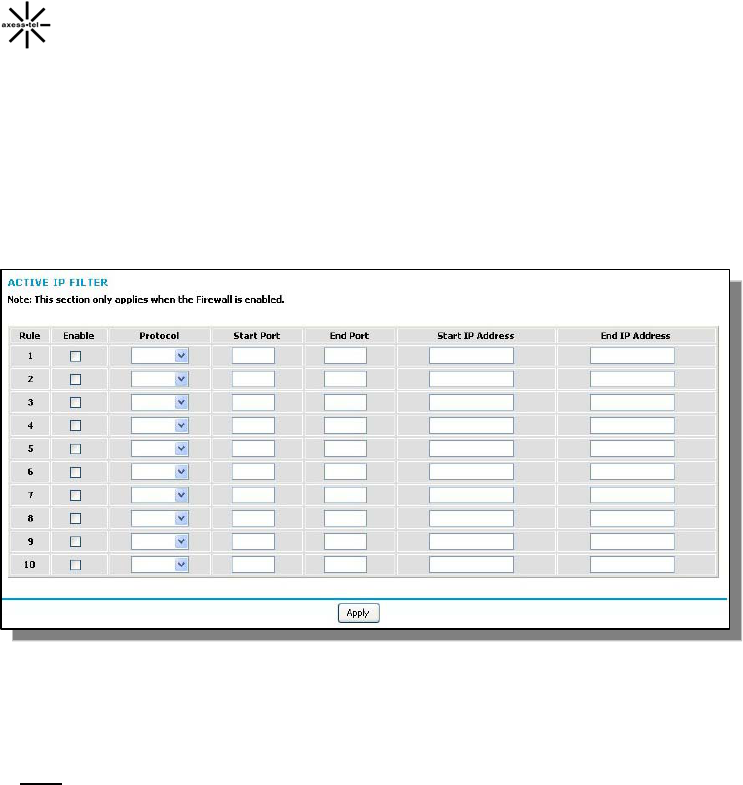
IP Filter
The Modem can be configured to restrict access to the Internet, email, or other
network services at specific days and times. Restriction can be set for a single c
omputer, a range of computers, or multiple computers.
To restrict Internet access to a single computer, for example, enter the Start/End
IP address of the computer you wish to restrict access to in the IP fields. Next,
choose “Protocol” as “TCP/UDP”, enter “80” in both the port fields. Click “Apply”.
Note: To enable this function, you should active “Firewall” function in “Fire
wall/DMZ Services”.
32
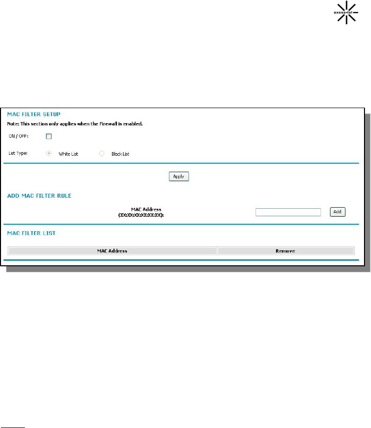
MAC Filter
The MAC address filter is a powerful security feature that allows you to specify
which computers are allowed on the network. Any computer attempting to
access the network that is not specified in the filter list will be denied access.
When you enable this feature, you must enter the MAC address of each client
(computer) on your network to allow network access to each.
To use MAC Filter function, you should check “ON/OFF” box at first.
When MAC Filter Services is enabled, it can be set in 2 modes.
Black List. In this mode, the service table shows the client MAC address
being blocked by the Modem.
White List. In this mode, the service table shows the client MAC
address allowed by the Modem.
To add a MAC address into the service table, simply enter the MAC address
and click “Add”.
Note: You will not be able to delete the MAC address of the computer you are
using to access the Router’s administrative functions (the computer you are
using now).
33
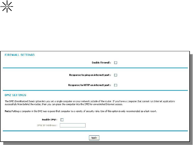
Firewall/DMZ Services
Clicking on the header of the “Firewall/DMZ Services” tab will take you to the “F
irewall/DMZ Services” header page. From this page, the Modem’s Firewall &
DMZ can be enabled or disabled.
WAN Ping Blocking
Computer hackers use what is known as “pinging” to find potential victims on
the Internet. By pinging a specific IP address and receiving a response from the
IP address, a hacker can determine that something of interest might be there.
The Modem can be set up so it will not respond to a ping request from WAN.
This heightens the level of security of your Modem.
To turn OFF the ping response, enable firewall at first, then uncheck “Respond
to ping on internet port” and click “Apply”. The Modem will not respond to any
ping from WAN.
HTTP Request Blocking
Computer hackers will also use HTTP request to attack your modem sometime,
also you can block the HTTP request from WAN by setting on modem.
To turn OFF the HTTP response, enable firewall at first, then uncheck
“Respond to HTTP on Internet Port” and click “Apply”. The Modem will not
respond to any HTTP ping.
34
Enabling the Demilitarized Zone (DMZ)
The DMZ feature allows you to specify one computer on your network to be
placed outside of the firewall. This may be necessary if the firewall is causing
problems with an application such as a game or video conferencing application.
Use this feature on a temporary basis. The computer in the DMZ is NOT
protected from hacker attacks.
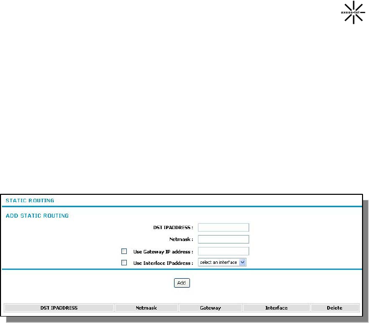
Static Routing
A static IP address connection type is less common than other connection types.
If your ISP uses static IP addressing, you will need your IP address, subnet
mask, and ISP gateway address. This information is available from your ISP or
on the paperwork that your ISP left with you. Type in your information, and click
“Apply”.
1. DST IPAddress: Provided by your ISP. Enter your IP address here.
2. Net Mask: Provided by your ISP. Enter your subnet mask here.
3. Gateway Address: Provided by your ISP. Enter the ISP gateway address
here.
4. Interface: Provided by your ISP. Enter the Interface here.
35
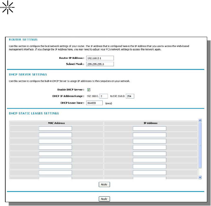
LAN Setting
Clicking on the header of the “LAN Setting” tab will take you to its header page.
Router Setting
All settings for the internal LAN setup of the Router can be viewed and changed
here.
1. Router IP Address: The “Router IP address” is the internal IP address of the
Modem. The default IP address is “192.168.0.1”. To access the Web Manager U
ser Interface, type this IP address into the address bar of your browser. This ad
dress can be changed if needed. To change the IP address, type in the new IP a
ddress and click “Apply”. The IP address you choose should be a non-
routable IP.
Examples of a non-routable IP are:
36
192.168.x.x (where x is anything between 0 and 255), and
10.x.x.x (where x is anything between 0 and 255).
2. Subnet Mask: There is no need to change the subnet mask. This is a unique,
advanced feature of your Modem. It is possible to change the subnet mask if
necessary; however, do NOT make changes to the subnet mask unless you
have a specific reason to do so. The default setting is “255.255.255.0”.
Enable DHCP Server
The DHCP server function makes setting up a network very easy by assigning I
P addresses to each computer on the network automatically. The DHCP server
can be turned OFF if necessary; however, in order to do so you must manually
set a static IP address for each computer on your network. To turn off the DHCP
server, de-select “Enable DHCP Server” and click “Apply”.
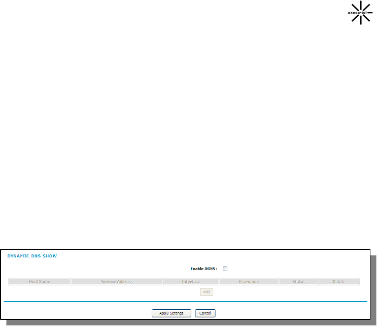
Dynamic DNS
Clicking on the header of the “Dynamic DNS” tab will take you to its header
page.
To use DDNS function, just select “Enable DDNS” then input the usernam
e/password you got from your service provide and click “apply”.
3G Information

37
Troubleshooting
Problem:
• The Install software completed installation, but my web browser
doesn’t work.
• I am unable to connect to the Internet. The Modem’s “Signal” light is
on and the “Connect” light is off.
Solution:
If you cannot connect to the Internet, the “Signal” light is on, and the
“Connect” light is off, the problem may be your connection type may not
match the ISP’s connection.
• If you have a “static IP address” connection, your ISP must assign
you the IP address, subnet mask, and gateway address. Please
refer to the section entitled “Alternate Setup Method” for details on
changing this setting.
• If you are still unable to access the Internet after verifying these
settings, please contact your Service Provider Technical Support.
Problem:
• The Install software completed installation, but my web browser
doesn’t work.
• I am unable to connect to the Internet. The Modem’s “Signal” light is
on and the “Connect” light is on.
Solution:
If the “Signal” light is on, and the “Connect” light is on, but you are unable to
access the Internet, there may be third-party firewall software installed on
the computer attempting to access the Internet. Examples of third-party
firewall software are ZoneAlarm, BlackICE PC Protection, McAfee Personal
Firewall, and Norton Personal Firewall.
If you do have firewall software installed on your computer, please make
sure that you properly configure it. You can determine if the firewall software
is preventing Internet access by temporarily turning it off. If, while the
firewall is disabled and Internet access works properly, you will need to

38
change the firewall settings to function properly when it is turned on.
Please refer to the instructions provided by the publisher of your firewall
software for instructions on configuring the firewall to allow Internet access.
If you are still unable to access the Internet after disabling any firewall
software, please contact your Service Provider Technical Support.
Problem:
I can’t connect to the Internet wirelessly from my computer but it works if I
use the Ethernet cable.
Solution:
If you are unable to connect to the Internet from a wireless computer,
please do the following:
1. Look at the lights on your Modem. Your Modem’s lights should be as
follows:
• The “Power” light should be on.
• The “Connected” light should be on and not blinking.
• The “WAN” light should be either on or blinking.
2. Open your wireless utility software by clicking on the icon in the
system tray at the bottom, right-hand corner of the screen.
3. The exact window that opens will vary depending on the model of
wireless card you have; however, any of the utilities should have a list
of “Available Networks”—those wireless networks it can connect to.
Problem:
My wireless network performance is inconsistent.
Data transfer is sometimes slow.
Signal strength is poor.
I am having difficulty establishing and/or maintaining a Virtual Private
Network (VPN) connection.
Solution:
Wireless technology is radio-based, which means connectivity and the
throughput performance between devices decreases when the distance

39
between devices increases. Other factors that will cause signal degradation
(metal is generally the worst culprit) are obstructions such as walls and
metal appliances. As a result, the typical indoor range of your wireless
devices will be between 100 to 200 feet. Note also that connection speed
may decrease as you move farther away from the Modem or access point.
In order to determine if wireless issues are related to range, we suggest
temporarily moving the computer, if possible, five to 10 feet away from the
Modem.
Changing the Wireless Channel - Depending on local wireless traffic and
interference, switching the wireless channel of your network can improve
performance and reliability. The default channel the Modem is shipped with
is channel 11. You may choose from several other channels depending on
your region (see the section titled “Changing the Wireless Channel” on page
41 for instructions on how to choose other channels).
Limiting the Wireless Transmit Rate - Limiting the wireless transmit rate can
help improve the maximum wireless range and connection stability. Most
wireless cards have the ability to limit the transmission rate. To change this
property, go to the Windows Control Panel, open “Network Connections”
and double-click on your wireless card’s connection. In the “Properties”
dialog, select the “Configure” button on the “General” tab (Windows 98
users will have to select the wireless card in the list box and then click
“Properties”), then choose the “Advanced” tab and select the rate property.
Wireless client cards are usually set to automatically adjust the wireless
transmit rate for you, but doing so can cause periodic disconnects when the
wireless signal is too weak; as a rule, slower transmission rates are more
stable.
Experiment with different connection rates until you find the best one for
your environment; note that all available transmission rates should be
acceptable for browsing the Internet. For more assistance, see your
wireless card’s user manual.

40
Technical Specifications
This chapter provides technical product data for the Modem.
Radio frequency and electrical specifications
Frequency
Range MV411 Rx: 463 ~ 468 MHz
Tx: 453 ~ 458 MHz
Frequency
Range MV441 Rx: 859.64 ~ 893.37 MHz
Tx: 824.64 ~ 848.37 MHz
Frequency
Range
MV441 Rx: 1930 ~ 1989.95 MHz
Tx: 1850 ~ 1909.95 MHz
Channel Bandwidth CDMA 1.23 MHz
Stability of frequency 0.4 ppm
External appearance (mm) 160 x 178 x 40 mm
Weight 600 g (with battery)
Sending output maximum 0.23W E.R.P
Temperature of operation
Relative humidity
-20 ~ +50 degrees Celsius
5% ~ 90%
Adapter Input: AC 100~240V 50~60Hz
Output: DC 12V/1A
Battery Operation
2.5 Hrs
AXT_GD_v1.0

41
Appendix A: Glossary
1X One Times Radio Transmission Technology (the “one times”
refers to the frequency spectrum). Supports Internet connections
with data rates up to 153 Kbps. Actual speed depends on the
network conditions. Compare to 1x EV-DO.
1x-EVDO A high speed standard for cellular packet data communications
Rev. A supports Internet connections with data rates up to3.1
Mbps (downlink from the network) and 1.8 Mbps (uplink to the
network).
Rev. 0 supports Internet connections with data rates up to 2.4
Mbps (downlink from the network) and 153 Kbps (uplink to the
network).
Average data rates are roughly: for Rev. A: 600–1300 Kbps
(downlink from the network) and 300–400 Kbps (uplink to the
network); for Rev. 0: 400–700 Kbps (downlink from the network)
and 40 80 Kbps (uplink to the network). ‐
Actual speed depends on the network conditions. Compare to 1X.
bps bits per second—The actual data speed over the transmission
medium.
CDMA Code Division Multiple Access—A wideband spread spectrum
technique used in digital cellular, personal communications
services, and other wireless networks. Wide channels (1.25 MHz)
are obtained through spread spectrum transmissions, thus
allowing many active users to share the same channel. Each user
is assigned a unique digital code, which differentiates the
individual conversations on the same channel.
CDMA 1X Also known as 1X, this is a high speed standard for CDMA
cellular communications.
dormant The packet data connection has the logical PPP session left open
while the underlying physical link (the radio channel) is released.
When traffic is to resume, a radio channel is reacquired and the
original PPP session resumes.

42
ESN Electronic Serial Number—The unique first generation serial
number assigned to the Modem for cellular network use.
Compare to MEID.
FCC Federal Communications Commission. The U.S. federal agency
that is responsible for interstate and foreign communications. The
FCC regulates commercial and private radio spectrum
management, sets rates for communications services, determines
standards for equipment, and controls broadcast licensing.
Consult www.fcc.gov.
firmware Software stored in ROM or EEPROM; essential programs that
remain even when the system is turned off. Firmware is easier to
change than hardware but more permanent than software stored
on disk.
host 1. A computer that uses a modem or a similar device to answer a
calling computer.
2. A source or destination in the communication network.
3. A computer that contains data or files to be accessed by client
computers. Also known as a server.
IS Interim Standard—After receiving industry consensus, the TIA
forwards the standard to ANSI for approval.
IS-95 The standard for CDMA
Kbps Kilobits per second—Actually 1000, not 1024, as used in
computer memory size measurements of kilobytes.
LAN Local Area Network
LED Light Emitting Diode—A semiconductor diode that emits visible or
infrared light.
MEID Mobile Equipment Identifier—The unique second-generation
serial number assigned to the Modem for cellular network use.
Compare to ESN.
MHz Mega Hertz—One million cycles per second.
Mbps Megabits per second
packet A short fixed length block of data including a header that is ‐

43
transmitted as a unit in a communications network.
PCS Personal Communications Services—A cellular communication
infrastructure that uses a different frequency range than AMPS.
roaming A cellular subscriber is in an area where service is obtained from
a cellular service provider that is not the subscriber’s provider.
RUIM Removable User Identity Module. By having a removable identity
card, CDMA users can change phones while keeping their phone
numbers by simply swapping the cards.
SMS Short message services—A feature that allows users of a
wireless device on a wireless network to receive or transmit short
electronic alphanumeric messages (up to 160 characters,
depending on the service provider).
system tray Usually located in the lower right corner of your screen
TIA Telecommunications Industry Association—A standards-setting
trade organization, whose members provide communications and
information technology products, systems, distribution services
and professional services in the United States and around the
world. Consult www.tiaonline.org.
VPN Virtual Private Network
FCC Regulations:
This device complies with part 15 of the FCC Rules. Operation is subject
to the following two conditions: (1) This device may not cause harmful inte
rference, and (2) this device must accept any interference received, includi
ng interference that may cause undesired operation.
This device has been tested and found to comply with the limits for a Cla
ss B digital device, pursuant to Part 15 of the FCC Rules. These limits are
designed to provide reasonable protection against harmful interference in a
residential installation. This equipment generates, uses and can radiated r
adio frequency energy and, if not installed and used in accordance with the

44
instructions, may cause harmful interference to radio communications. Ho
wever, there is no guarantee that interference will not occur in a particular
installation If this equipment does cause harmful interference to radio or t
elevision reception, which can be determined by turning the equipment off
and on, the user is encouraged to try to correct the interference by one or
more of the following measures:
-Reorient or relocate the receiving antenna.
-Increase the separation between the equipment and receiver.
-Connect the equipment into an outlet on a circuit different from that to
which the receiver is connected.
-Consult the dealer or an experienced radio/TV technician for help.
Changes or modifications not expressly approved by the party responsible
for compliance could void the user‘s authority to operate the equipment.
4RF Exposure Information
This device meets the government’s requirements for exposure to radio
waves.
This device is designed and manufactured not to exceed the emission
limits for exposure to radio frequency (RF) energy set by the Federal
Communications Commission of the U.S. Government.
This device complies with FCC radiation exposure limits set forth for an
uncontrolled environment. In order to avoid the possibility of exceeding the
FCC radio frequency exposure limits, human proximity to the antenna shall
not be less than 20cm (8 inches) during normal operation.

45