Axesstel MV540V CDMA/ PCS CDMA 1x EV-DO Rev.A Wi-Fi Gateway User Manual
Axesstel Inc CDMA/ PCS CDMA 1x EV-DO Rev.A Wi-Fi Gateway
UserManual.wiki
>
Axesstel
>
MV540V User Manual
User manual
Navigation menu
Upload a User Manual
Namespaces
Wiki Guide
HTML
PDF
Info
Views
User Manual
Discussion / Help
Navigation
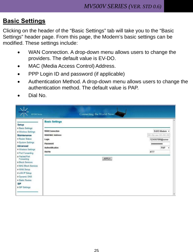
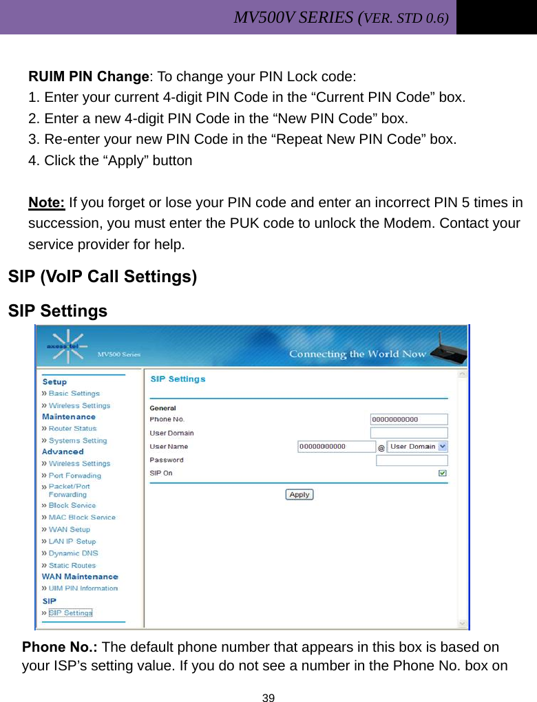
![MV500V SERIES (VER. STD 0.6) 24 Navigate WEB GUI The Basic Settings page is the first page you will see when you access the Web-based Advanced User Interface (WEB GUI). This page presents a quick view of the Modem’s login setting. All advanced setup pages can be reached from this page. [1] Quick Navigation Links You can go directly to any of the Modem’s UI pages by clicking directly on these links. For ease in finding a particular setting, the links are divided into logical categories and grouped by tabs. [2] Page Name The page you are on can be identified by its page name. This User Manual sometimes refers to pages by name. For example, “Advanced > LAN IP Setup” refers to the “LAN IP Setup” page. [3] SIP Settings In this page, you can set SIP accounts and control for VoIP call functions.](https://usermanual.wiki/Axesstel/MV540V/User-Guide-1314809-Page-25.png)
![MV500V SERIES (VER. STD 0.6) 44 SETTING CALLER ID If the phone connected to your Modem is Caller ID-enabled, you can set the Modem to display a caller’s identification number or name on your phone’s LCD display. To set Caller ID through the Modem: 1. Lift the handset from your phone. 2. Press <*><*><2><1><0><#> to disable Caller ID. [Disable or Enable? Why explaining disabling first?] 3. Press <*><*><2><1><1><#> to enable DTMF Standard Type. 4. Press <*><*><2><1><2><#> to enable FSK (Bellcore) Type. Note: The default setting for Caller ID is DTMF Type.](https://usermanual.wiki/Axesstel/MV540V/User-Guide-1314809-Page-45.png)