Axesstel MV540V CDMA/ PCS CDMA 1x EV-DO Rev.A Wi-Fi Gateway User Manual
Axesstel Inc CDMA/ PCS CDMA 1x EV-DO Rev.A Wi-Fi Gateway
Axesstel >
User manual
MV500V SERIES (VER. STD 0.6)
1
Important Notice
Due to the nature of wireless communications, transmission and reception of data
can never be guaranteed. Data may be delayed, corrupted (i.e., have errors) or be
totally lost. Although significant delays or losses of data are rare when wireless
devices such as the Axesstel modem are used in a normal manner with a well-
constructed network, the Axesstel modem should not be used in situations where
failure to transmit or receive data could result in damage of any kind to the user or
any other party, including but not limited to personal injury, death or loss of
property. Axesstel accepts no responsibility for damages of any kind resulting from
delays or errors in data transmitted or received using the Axesstel modem or for
failure of the Axesstel modem to transmit or receive such data.
Safety Precautions
Do not operate the Axesstel modem:
¾ In areas where blasting is in progress
¾ Where explosive atmospheres may be present
¾ Near medical equipment
¾ Near life support equipment or any equipment that may be susceptible to
any form of radio interference. In such areas, the Axesstel modem MUST
BE POWERED OFF. The Axesstel modem can transmit signals that could
interfere with this equipment.
Do not operate the Axesstel modem in any aircraft, whether the aircraft is on the
ground or in flight. In aircraft, the Axesstel modem MUST BE POWERED OFF.
When operating, the Axesstel modem can transmit signals that could interfere
with various onboard systems.
Note: Some airlines may permit the use of cellular phones while the aircraft is on
the ground and the door is open. The Axesstel modem may be used at this time.
The driver or operator of any vehicle should not operate the Axesstel modem
while in control of a vehicle. Doing so will detract from the driver or operator’s
control and operation of that vehicle. In some states and provinces, operating
such communications devices while in control of a vehicle is an offense.

MV500V SERIES (VER. STD 0.6)
2
Limitation of Liability
The information in this manual is subject to change without notice and does not
represent a commitment on the part of Axesstel. AXESSTEL SPECIFICALLY
DISCLAIMS LIABILITY FOR ANY AND ALL DIRECT, INDIRECT, SPECIAL,
GENERAL, INCIDENTAL, CONSEQUENTIAL, PUNITIVE OR EXEMPLARY
DAMAGES INCLUDING, BUT NOT LIMITED TO, LOSS OF PROFITS OR
REVENUE OR ANTICIPATED PROFITS OR REVENUE ARISING OUT OF THE
USE OR INABILITY TO USE ANY AXESSTEL PRODUCT, EVEN IF AXESSTEL
HAS BEEN ADVISED OF THE POSSIBILITY OF SUCH DAMAGES OR THEY
ARE FORESEEABLE OR FOR CLAIMS BY ANY THIRD PARTY.
Notwithstanding the foregoing, in no event shall Axesstel aggregate liability arising
under or in connection with the Axesstel product, regardless of the number of
events, occurrences, or claims giving rise to liability.

MV500V SERIES (VER. STD 0.6)
3
Introduction
Placement of Your Modem for Optimal Performance
Product Overview
Using Your Modem
Package Contents
Modem Interfaces
Connecting and Configuring Your Modem
Setting Up the Hardware
Preparing Your PC
Connection Using Ethernet (RJ-45) Ports
Configuring Your PC
Configuring an Ethernet Connection
Web manager user interface (Web GUI)
Navigate Web-Based UI
Troubleshooting
Technical Specifications
Appendix A: Glossary

MV500V SERIES (VER. STD 0.6)
4
INTRODUCTION
Thank you for purchasing the Axesstel MV500V series EV-DO Modem with VoIP
feature (the Modem). This user manual will help you setup, configure and outline
best practices for maximizing your wireless home network performance with the
Modem. Please be sure to read through this User Manual completely, and pay
special attention to the section below entitled “Placement of Your Modem for
Optimal Performance.”
PLACEMENT OF YOUR MODEM FOR OPTIMAL PERFORMANCE
The closer your computer is to your Modem, the stronger your wireless
connection will be. Typical indoor operating range for Wi-Fi wireless devices is
between 100 and 200 feet. For EV-DO operation, placing the Modem in a line of
sight with the radio base station will yield the strongest signal.
Similarly, your wireless connection and performance will degrade a bit as the
distance increases between your Modem and connected devices and between
your Modem and radio base station. This change may or may not be noticeable to
you.
As you move your computer farther from your Modem, connection speed may
decrease. This may happen due to walls, metal appliances or other elements
obstructing your network’s radio waves and weakening its signals..
Note: While some of the items listed below can affect network performance, they
will not prohibit your wireless network from functioning. If you are concerned that
your network is not operating at maximum effectiveness, this checklist may help.
1. Modem Placement
Place your Modem, the central connection point of your network, as close as
possible to windows or in rooms along the perimeter of your house. If you also
use the Wi-Fi feature of the Modem, place the Modem centrally within your
network of wireless devices..
To achieve the best wireless network coverage:

MV500V SERIES (VER. STD 0.6)
5
• Ensure that your Modem’s CDMA networking antennas are parallel to
each other and positioned vertically (pointed toward the ceiling). If your
Modem is positioned vertically, point the antennas upward as best as
possible.
• In multi-story homes, place the Modem on an upper floor.
• Try not to place the Modem near a cordless phone (MV500-series only).
2. Avoid Obstacles and Interference
Avoid placing your Modem near microwave ovens and other devices that may
emit radio “noise.” Dense objects that can inhibit wireless communication include:
• Refrigerators
• Washers and/or dryers
• Metal cabinets
• Large aquariums
• Metallic-based, UV-tinted windows
If your wireless signal seems weak in some spots, move the Modem to another
location while observing the signal strength indicator. Since you may not know the
location of an EV-DO radio base station serving your Modem, call your service
provider and ask for the location of the nearest base station to your home. Place
your Modem as close as possible to that base station and in an unobstructed line
of sight.
3. Cordless Phones
If the performance of your wireless network is impaired after addressing the above
issues, and if you have a cordless phone:
• Move the cordless phone away from your Modem and wireless-enabled
computers.
• Unplug and remove the battery from any cordless phone that operates on
the 2.4GHz band (check the manufacturer’s literature for this information).
If this fixes the problem, your phone may be interfering with your wireless
network’s performance.
• If your phone supports channel selection, change the channel on the
phone to the farthest channel from your wireless network. For example,
set the phone to channel 1 and set your Modem to channel 11. See your

MV500V SERIES (VER. STD 0.6)
6
phone’s user manual for detailed instructions.
If necessary, consider switching to a 900MHz cordless phone.
PRODUCT OVERVIEW
In minutes, you will be able to connect your computers to the Internet, share your
Internet connection and network your computers. And you will be able to make a
call through VoIP. The following is a list of features that make your new Axesstel
EV-DO Modem an ideal solution for your home or small office network.
Implementation of these features depends on the particular service provider and
account features you have chosen.
Some features described in this manual may not be supported by your service
provider or may not be available with your network account. For details of the
services and accounts available, contact your service provider.
CDMA 3G Services
Your Modem operates on CDMA 3G technology that provides a variety of
connectivity features. Depending on your service provider and account, you may
be able to access some or all of these features:
• 1xEV-DO Rev. A supports Internet connections with data rates up to 3.1
Mbps (on the downlink from the network) and 1.8 Mbps (on the uplink
to the network). Average data rates are 600–1300 Kbps (on the
downlink) and 300–400 Kbps (on the uplink). Actual speed depends on
network conditions.
• 1xEV-DO Rev. 0 supports Internet connections with data rates up to 2.4
Mbps (on the downlink) and 153 Kbps (on the uplink). Average data
rates are 400–700 Kbps (on the downlink) and 40–80 Kbps (on the
uplink). Actual speed depends on network conditions.
• 1X supports Internet connections with data rates up to 153 Kbps. Actual
speed depends on network conditions.
Once an Internet connection is established, you can open your browser and
connect to any web site that is accessible through the Internet or access other
Internet services such as email.

MV500V SERIES (VER. STD 0.6)
7
A connection is “active” when data transmission is occurring. If data transmission
stops for a period of time (determined by the network), the connection becomes
“dormant.” For more information, see page 26.
VoIP Calling
Your Modem (MV500V series) features a Voice over Internet Protocol (VoIP)
function that allows you to make voice calls over a VoIP network by simply
connecting a wired, landline phone to your network-connected Modem.
The basic operating principles behind VoIP: the Modem receives an analog voice
signal from your wired phone, converts the analog signal into a digital signal,
compresses the digital signal into IP packets, and then transmits the IP packets
over the internet. This process is reversed at the receiving end.
Your Modem meets standard VoIP protocol, SIP 2.0, and provides a single RJ-11
port for single-line use. Once your Modem is activated and SIP accounts have
been set on your service provider’s network, you can start making VoIP calls.
Plug-and-Play
Your Modem was factory-set for compatibility with a particular service provider.
Thus, your Modem operates on radio channels and enables services specific to
your network service provider. Once your Modem has been activated on your
service provider’s network, you can connect to the Internet. (Activation is the
process of setting up an account with a service provider and configuring the
Modem to work on that provider’s network.)
After your Modem is activated, connect it to your computer using the provided
Ethernet (RJ-45) cable. You are now ready to use the Internet.
Works With PCs and Mac® Computers
Your Modem supports a variety of networking environments including Mac OS®
9.x, X v10.x, AppleTalk®, Linux®, Windows® NT®, 2000, XP, and others. You will
also need an Internet browser and a network adapter that supports TCP/IP (the
standard language of the Internet).

MV500V SERIES (VER. STD 0.6)
8
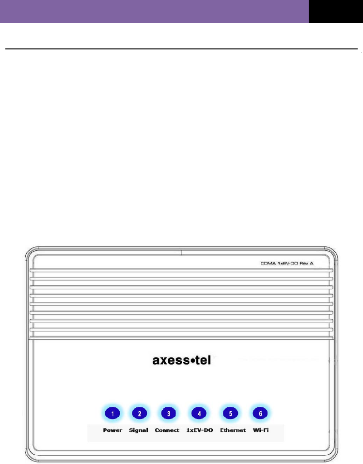
Top-View LED Display
LED lights on the top of the Modem indicate which functions are operating. The
LED lights allow you to know at a glance if your Modem is in EV-DO or 1X mode,
connected to the Internet and in Wi-Fi or Ethernet operation. This feature
eliminates the need for advanced software and status-monitoring procedures.
Web-Based Advanced User Interface
You can easily setup the Modem’s advanced functions through your
AxessManager web browser and without having to install additional software onto
your computer. There are no disks to install or keep track of. And, best of all, you
can make changes and perform setup functions from any computer on the
network—quickly and easily.
NAT IP Address Sharing
Your Modem employs Network Address Translation (NAT). NAT allows your
networked computer devices to share a single IP address, saving the cost of
adding IP addresses to your Internet service account.
Integrated 10/100 4-Port Switch
The Modem has a built-in, 4-port network switch to allow your wired computers to
share printers, data, MP3 files, digital photos and much more. The switch features
automatic detection so it will adjust to the speed, half duplex, and full duplex of
connected devices. The switch transfers data between computers and the Internet
simultaneously without interrupting or consuming resources.
Support for VPN Pass-Through
If you connect to your office network from home using a VPN connection, your
Modem will allow your VPN-equipped computer to pass through the Modem and
to your office network.
Built-In Dynamic Host Configuration Protocol (DHCP)
Built-In Dynamic Host Configuration Protocol (DHCP) makes for easiest possible
networking. The DHCP server automatically assigns IP addresses to each
computer, eliminating the need for a complicated networking setup.
Integrated 802.11g Wireless Access Point
802.11g is an exciting new wireless technology that achieves data rates up to

MV500V SERIES (VER. STD 0.6)
9
54Mbps, nearly five times faster than 802.11b.
MAC Address Filtering
For added security, you can create a list of MAC addresses (unique client
identifiers) that are allowed access to your network. Every computer has its own
MAC address. Enter these MAC addresses into a list using the Web-Based
Advanced User Interface, and you can control access to your network.
MV500V SERIES (VER. STD 0.6)
10
USING YOUR MODEM
Package Contents
• EV-DO Modem
• User Manual
• Quick Installation Guide
• RJ-45 Ethernet Networking Cable
• RJ-11 phone cable for VoIP
• Power Supply and Battery
Modem Interfaces
The Modem is designed to be placed on a desktop or wall mounted. All ports at
the front of the Modem are for better organization and utility. The LED indicators
are easily visible on the top of the Modem to provide you with information about
network activity and status.
MV500V SERIES (VER. STD 0.6)
11
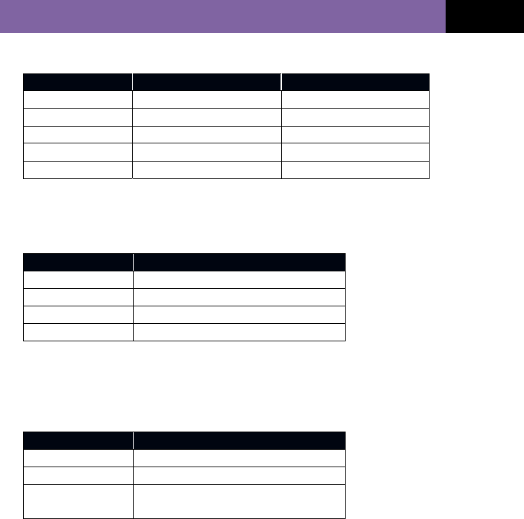
1. Power LED
LED Color AC Mode Battery Mode
OFF No Power No Power
Blue Solid Adaptor Connected Fully Charged
Blue Blinking In Charging -
Violet - Half Level Charged
Red - Low Level Charged
2. Signal Strength LED
This LED indicates the signal strength of the CDMA network serving the Modem.
LED Color Status
OFF No CDMA signal
Blue Strongest Level
Violet Medium Level
Red Low Level
3. Connect LED
This LED informs you that the Modem is connected to a wireless network and
that your user ID and password have been validated.
LED Color Status
OFF No connection
Blue Blinking Voice Message Waiting
Blue - In Data use: Connected
- In VoIP call use: In use
4. 1x/EV-DO LED
This LED informs you that the Modem is tuned to a 1x or EV-DO wireless
network. Your Modem is programmed to search and use an EV-DO network. If
an EV-DO network is unavailable, the Modem will search for a 1x network.
Please check with your Service Provider for your Modem’s default setting.
MV500V SERIES (VER. STD 0.6)
12
LED Color Status
OFF 1x
Blue EV-DO
5. Ethernet LED
This LED indicates that computers are connected to your Modem via the RJ-45
ports. A blinking LED indicates activities of data passing through.
LED Color Status
OFF No Ethernet connection
Blue Solid At least one RJ-45 port is in use
Blue Blinking Data is passing through the ports
6. Wi-Fi LED
This LED indicates that your Modem has Wi-Fi capability. When the LED is
blinking, it indicates activities of data passing through.
LED Color Status
OFF No Wi-Fi
Blue Solid Wi-Fi network within Modem activated
Blue Blinking Data passing through Wi-Fi
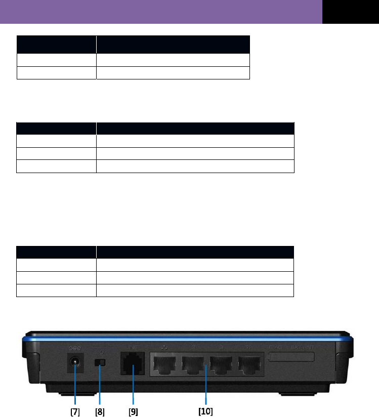
7. Power Jack
Connect the Axesstel standard 9V DC power Adaptor to this jack.
MV500V SERIES (VER. STD 0.6)
13
8. Power On/Off Switch
9. RJ-11 Connection Port (MV500S and MV500V Series only)
** Please refer to the function table on page 38 to understand derivative products.
This port allows your Modem to connect to a wired landline phone for Voice
Calls.
10. Connections to Computers (Wired Computer Ports)
Connect your wired (non-wireless) computers to these ports. These ports are
RJ-45, 10/100 auto-negotiation, auto up-linking ports for standard UTP
category 5 or 6 Ethernet cable. The ports are labeled 1 through 4.
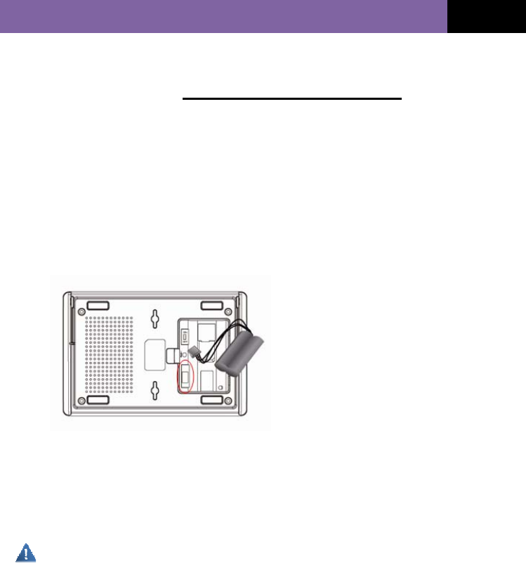
11. Rechargeable Battery Installation
① Disconnect the power supply.
② Open the battery cover on the bottom.
③ Connect the DC power cable to the unit marked above.
④ Close the battery cover
⑤ Connect the power supply to charge as needed.
Do not incinerate, disassemble, short or expose to heat.
Use designated charger only.
If battery is replaced by an incorrect type, there will be a risk of explosion.
System Components
Your Modem is part of a communication system offering a wide range of
capabilities. To enable these capabilities, you must have every component of the

MV500V SERIES (VER. STD 0.6)
14
system. Here’s what you need:
Host Computing Device
Your notebook or PC hosts the Modem and runs the communication software. The
communication software includes your web browser or email application and
Connection Manager, the Modem-enabling software.
You may also have other software on your computer that can be used wirelessly
with the Modem. Such software can include file transfer applications (FTP), chat
or instant messaging, VPN (Virtual Private Network) client and client software for
a corporate server application.
The Modem
The Modem provides your computer with a connection to the CDMA wireless
network. Every CDMA network operates on one of three radio frequency bands:
450MHz, 800MHz or 1900MHz. The Modem is available in four configurations:
MV510 single-band 450MHz, MV520 single-band 800MHz, MV530 single-band
1900MHz and MV540 dual-band 800/1900MHz.
CDMA Service Provider Account
Services providers are companies that operate CDMA networks and provide
access to these networks. To use the Modem, you must have an account with a
CDMA service provider.
Each service provider has its own pricing options. Flat rate accounts allow you to
purchase a maximum number of minutes of network usage for a fixed monthly fee.
Other types of accounts charge for network usage by the minute or by the amount
of data transmitted.
Your account may include a variety of other services such as SMS messaging.
Each Modem is designed for use with a particular service provider. Thus, your
Modem operates with specific radio channels and enables services specific to
your service provider.
Activation is the process of setting up your account. It involves action by your

MV500V SERIES (VER. STD 0.6)
15
service provider and over-the-network configuration of your Modem.
The CDMA Wireless Network
This is the worldwide infrastructure providing the radio coverage that allows you to
stay connected. Composed of radio towers and a variety of network switches,
routers and servers, the network is an interconnection of many service providers.
Note: More information about CDMA networks is available on the CDMA
Development Group web site, www.cdg.org.
CDMA networks operate in frequency bands supported by the Modem throughout
North America and parts of Latin America, Europe, Middle East, Africa and Asia-
Pacific. Each service provider operates a network covering a limited geographical
area within the overall CDMA coverage area.
Note: Some service providers have coverage maps on their web sites.
MV500V SERIES (VER. STD 0.6)
16
CONNECTING AND CONFIGURING YOUR MODEM
Each Modem is factory built for use with a particular service provider. Thus, each
Modem is set to use particular radio channels and to enable services specific to a
provider.
Once your Modem has been activated with the network, connect your computer to
the Modem using the provided Ethernet (RJ-45) cable. You are now ready to use
the Internet.
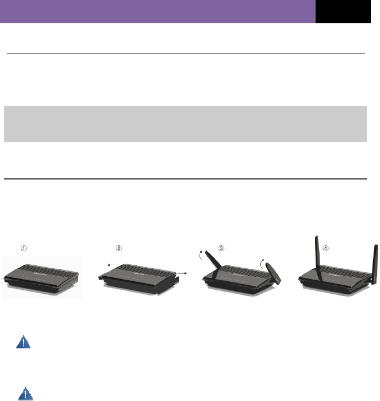
Step 1│ Setting Up the Hardware
1.1 Make sure your Modem is not connected to any power source and all LEDs
are OFF.
1.2 How to setup the Antennas for maximized performance:
① CDMA antennas are located on both sides of the Modem.
② Pull both antennas out until you hear clicking.
Antennas can be broken if you do not pull them out until clicking and if you try to force them up.
③ Make sure the antennas are upright as shown in picture 4 above. (vertically upright position)
④ Antennas rotate up to 90 degrees vertically and horizontally.
Antennas can be broken if you force them to more than 90 degrees from upright position.
1.3 Locate the CAT-5 Ethernet cable that is included with your Modem. Plug
one end of this cable into ANY Ethernet port on your Modem. Plug the other
end of the cable into the networking port on your computer.
1.4 Locate the power supply that is included with your Modem. Plug the power
supply’s small connector into the power port on the Modem. Plug the power
MV500V SERIES (VER. STD 0.6)
17
supply into an empty power outlet.
1.5 Switch on the Modem. Look at the Power LED on top of the Modem and
make sure the lights are ON.
1.6 Wait for a few seconds while the Modem searches for network service.
When the Modem finds a suitable network, the Signal LED turns to Red,
Violet or Blue depending on the strength of the acquired signal. Refer to the
Signal Strength LED description for more details.
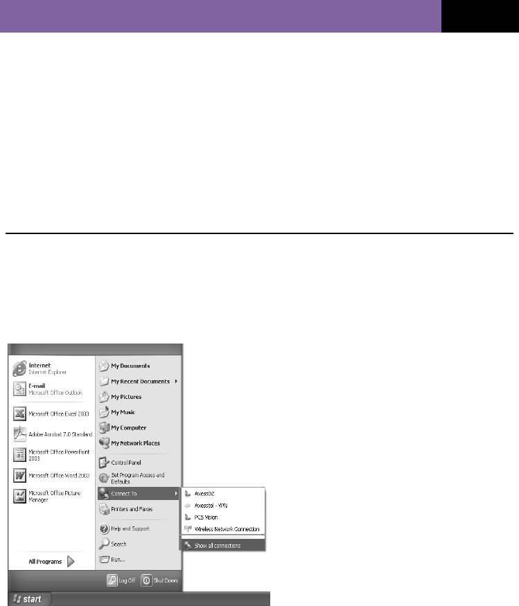
Step 2 │ Preparing Your PC
Your Modem’s Ethernet is configured with DHCP by default. This means that IP
address of your PC is automatically assigned by the Modem. Make sure that your
PC has the correct TCP/IP setting for its "Local Area Connection" by following the
steps below.
2.1 Click "Start", select "Connect To",
Scroll down to "Show all
connections" and left-click it.
2.2 Right-click "Local Area
Connection", Scroll down to
"Properties" and left-click it.
MV500V SERIES (VER. STD 0.6)
18
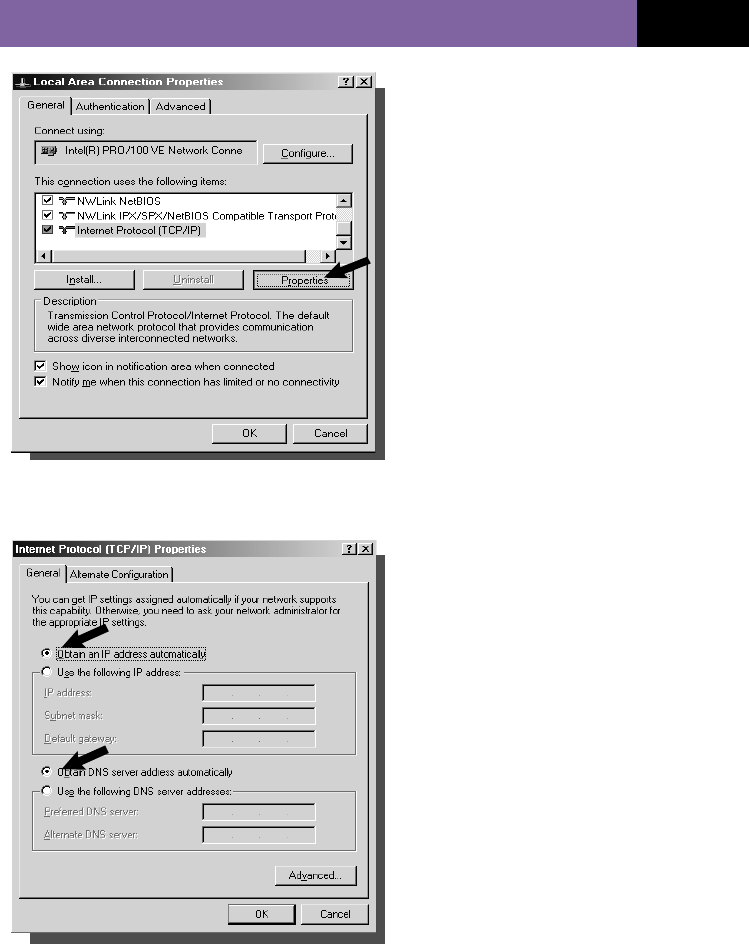
2.3 Select “Internet Protocol
(TCP/IP)”. Press the “Properties”
button.
If no TCP/IP line is listed, you will
need to install TCP/IP before
continuing.
2.4 Check “Obtain an IP address
automatically”
2.5 Check “Obtain DNS Server
address automatically”
2.6 Click “Ok” to exit “Properties”.
2.7 If asked to re-start the PC, click
“YES”.
MV500V SERIES (VER. STD 0.6)
19
CONNECTION USING ETHERNET (RJ-45) PORTS
If your Modem has been activated with the network, you can connect to the
Internet through the Ethernet (RJ-45) ports.
Configuring Your PC
The Modem’s Ethernet is configured with DHCP by default. This means that the
EV-DO Modem automatically assigns an IP address to your PC. If your PC is
unable to receive the IP address and prevented from making an Internet
connection, follow these steps to check the TCP/IP setting of your “Local Area
Connection.”
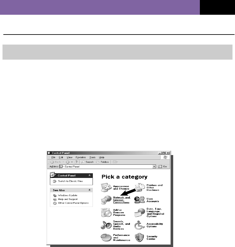
1. Click the “Start” button, select “Settings” and then select Control Panel. Click on
the “Network and Internet Connection” icon.
NOTE: DHCP stands for Dynamic Host Configuration Protocol. Your Modem has
a built-in DHCP server. The DHCP server will automatically assign an IP
address to the computers on the LAN. Be sure to set each client PC’s
TCP/IP settings to “obtain an IP address automatically.”
MV500V SERIES (VER. STD 0.6)
20
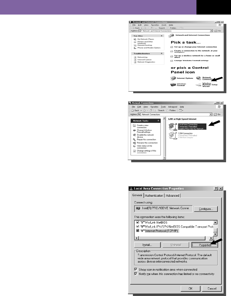
1 Double-click on “Network Connection”.
2 Go to “Local Area Connection Properties”.
3 Select the “Internet protocol (TCP/IP)”. If a TCP/IP line is not listed,
you will need to install TCP/IP before continuing.
4 Press the “Properties” button.
MV500V SERIES (VER. STD 0.6)
21
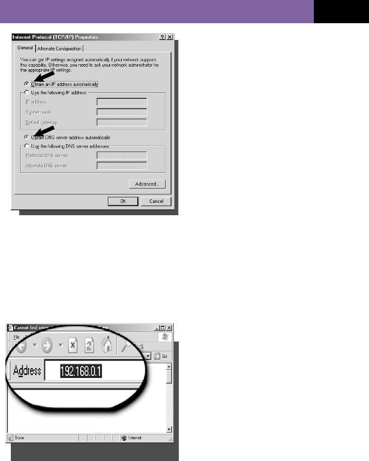
5 Check “Obtain an IP address
automatically”.
6 Check “Obtain DNS Server
address automatically”.
7 Click “OK” to exit “Properties”.
8 If asked to re-start the PC, click
“YES”.
Configuring an Ethernet Connection
Your EV-DO Modem provides an embedded Web-based Management Utility
(WEB GUI) to help you configure it using your web browser. Follow these steps to
configure your Modem’s Ethernet connection.
1. Open your web browser and enter
192.168.0.1 in the address bar.
MV500V SERIES (VER. STD 0.6)
22
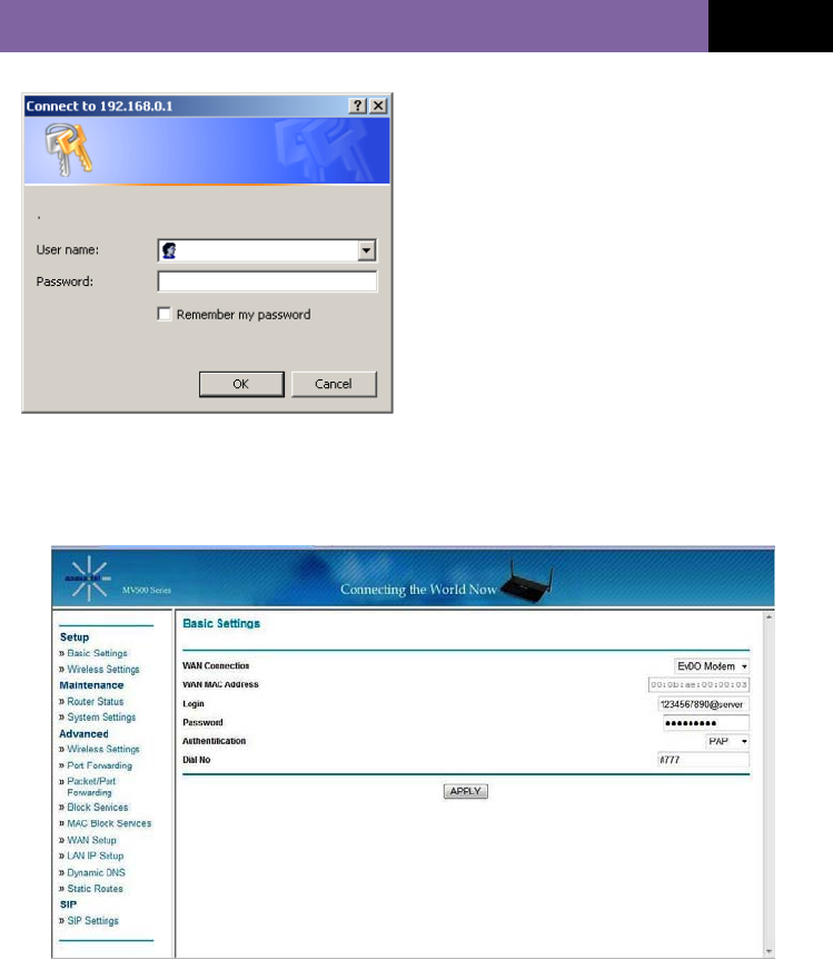
2. A pop-up window will appear. When
prompted for User name and
password, enter the following name
and password.
User Name: admin
Password: admin
* If you have changed the user name
and the password, enter the new
user name and password.
3. After entering the correct user name and password, the pop-up window will
change to a web-based window.
Follow the steps in the chapter “Web Manager User Interface”, “Step 2 Navigate
web-based UI”, page 39 to complete the Modem’s Ethernet and Wi-Fi settings.

MV500V SERIES (VER. STD 0.6)
23
WEB MANAGER USER INTERFACE (WEB GUI)
The Web Manager User Interface is a web-based tool that you can use to setup
the Modem. You can also use it to manage advanced functions of your Modem.
From the User Interface, you can perform these tasks:
• View the Modem’s current settings and status
• Configure the Modem's router and VoIP account log-in function to connect
to your Service Provider using the settings that they provided you
• Change current network settings such as the internal IP address, IP
address pool, DHCP settings and more
• Set the Modem’s firewall to work with specific applications (port
forwarding)
• Setup security features such as client restrictions, MAC address filtering,
WEP and WPA
• Enable the DMZ feature for a single computer on your network
• Change the Modem’s internal password
• Reboot the Modem
• Back up your configuration settings
• Reset the Modem’s default settings
• Update the Modem’s firmware
Before you can use the Advanced User Interface, you will need to have a User
Name and Password for your Modem. Please contact your Service Provider to
obtain a User Name and Password.
MV500V SERIES (VER. STD 0.6)
24
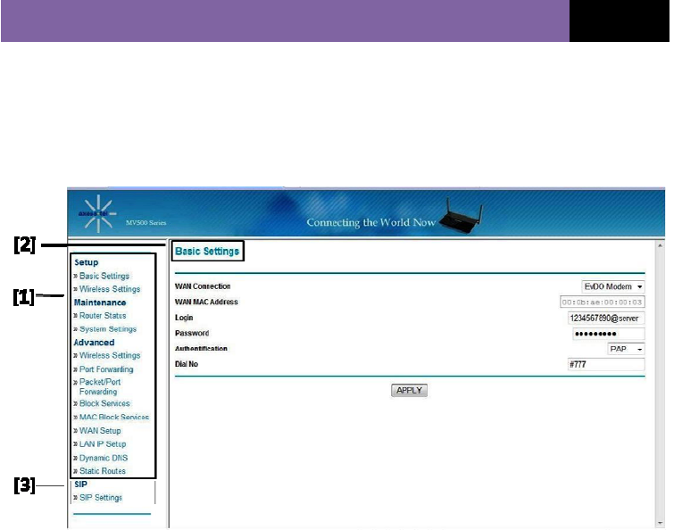
Navigate WEB GUI
The Basic Settings page is the first page you will see when you access the Web-
based Advanced User Interface (WEB GUI). This page presents a quick view of
the Modem’s login setting. All advanced setup pages can be reached from this
page.
[1] Quick Navigation Links
You can go directly to any of the Modem’s UI pages by clicking directly on
these links. For ease in finding a particular setting, the links are divided into
logical categories and grouped by tabs.
[2] Page Name
The page you are on can be identified by its page name. This User Manual
sometimes refers to pages by name. For example, “Advanced > LAN IP
Setup” refers to the “LAN IP Setup” page.
[3] SIP Settings
In this page, you can set SIP accounts and control for VoIP call functions.
MV500V SERIES (VER. STD 0.6)
25
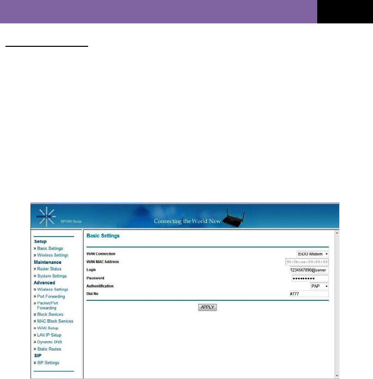
Basic Settings
Clicking on the header of the “Basic Settings” tab will take you to the “Basic
Settings” header page. From this page, the Modem’s basic settings can be
modified. These settings include:
• WAN Connection. A drop-down menu allows users to change the
providers. The default value is EV-DO.
• MAC (Media Access Control) Address.
• PPP Login ID and password (if applicable)
• Authentication Method. A drop-down menu allows users to change the
authentication method. The default value is PAP.
• Dial No.
MV500V SERIES (VER. STD 0.6)
26
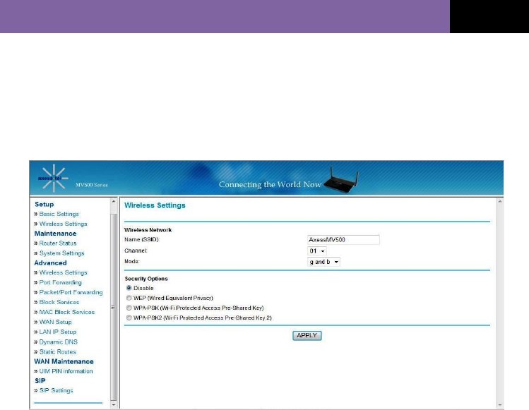
Configuring the Wireless Network Settings
Clicking on the header of the “Wireless Settings” tab will take you to the “Wireless
Settings” header page. From this page, the Modem’s Wi-Fi router wireless radio
can be enabled or disabled (the default setting is enabled). There are options that
allow you to make changes to the Wi-Fi wireless network settings.
Changing the Wireless Network Name (SSID)
To identify your wireless network, SSID (Service Set Identifier) is used. The
default SSID of your Modem is “AxessMV500”. You can change the SSID to
anything you want, or you can leave it unchanged. If there are other wireless
networks operating in your area, you will want to make sure that your SSID is
unique (does not match the SSID of another wireless network in your area). To
change the SSID, type in the SSID name that you want to use in the “SSID” field
and click “Apply Changes.”. The change is immediate. If you make a change to
the SSID, your wireless-equipped computers may also need to be reconfigured to
be able to connect to your new network name. Refer to the documentation of your
wireless network adapter for information on making this change.
Using the Wireless Mode Switch
Your Modem can operate in three different wireless modes: “g and b”, “g only”,
and “b only”.

MV500V SERIES (VER. STD 0.6)
27
g and b Mode
In this mode, the Modem is simultaneously compatible with 802.11b and
802.11g wireless clients. This is the factory default mode and ensures
successful operation with all Wi-Fi compatible devices. If you have a mix of
802.11b and 802.11g clients in your network, we recommend setting the
Modem to g and b mode. This setting should only be changed if you have a
specific reason to do so.
.g only Mode
g only mode works only with 802.11g clients. This mode is recommended if you
want to prevent 802.11b clients from accessing your network. To switch modes,
select the desired mode from the “Wireless Mode” drop-down box. Then, click
“Apply Changes”.
.b only Mode
We recommend you DO NOT use this mode unless you have a very specific
reason to do so. This mode exists only to solve unique problems that may
occur with some 802.11b client adapters and is NOT necessary for
interoperability of 802.11g and 802.11b standards.
When to use b only Mode
In some cases, older 802.11b clients may not be compatible with 802.11g
wireless. These adapters tend to be of inferior design and may use older drivers
or technology. Switching to this mode can solve problems that sometimes occur
with these clients. If you suspect that you are using a client adapter that falls
into this category of adapters, first check with the adapter vendor to see if there
is a driver update. If no driver update is available, switching to b only mode may
fix your problem. Please note that switching to b only mode will decrease
802.11g performance.
Changing the Wireless Channel
There are a number of operating channels you can choose from. In the United
States and Australia, there are 11 channels. In the United Kingdom and most of
Europe, there are 13 channels. In a small number of other countries, there are
other channel requirements. Your Modem is configured to operate on the
proper channels for the country you reside in. The default channel is 11 (unless
you are in a country that does not allow channel 11). The channel can be

MV500V SERIES (VER. STD 0.6)
28
changed, if necessary. If there are other wireless networks operating in your
area, your network should be set to operate on a channel that is different from
the other wireless networks. For best performance, use a channel that is at
least five channels away from other wireless networks. For example, if another
network is operating on channel 11, then set your network to channel 6 or
below. To change the channel, select the channel from the drop-down list and
click “Apply Changes”. The change is immediate.
Frequency channel only 1-11 channels are available in USA, other channels will
be disabled by software
Securing Your Wi-Fi® Network
Here are a few different ways you can maximize the security of your wireless
network and protect your data from prying eyes and ears. This section is
intended for the home, home office, and small office user. At the time of this
User Manual’s publication, two encryption methods are available.
WEP (Wired Equivalent Privacy)
WEP (Wired Equivalent Privacy) is a common protocol that adds security to all
Wi-Fi compliant wireless products. WEP was designed to give wireless
networks the equivalent level of privacy protection as a comparable wired
network.
WPA (Wi-Fi Protected Access) – PSK
WPA (Wi-Fi Protected Access) is a Wi-Fi standard that was designed to improve
upon the security features of WEP. To use WPA security, the drivers and
software of your wireless equipment must be upgraded to support WPA. These
updates will be found on the wireless vendor’s web site. There are two types of
WPA security, WPA-PSK (no server) and WPA (with radius server).
WPA-PSK (no server) uses a pre-shared key as the network key. A network key
is a password that is between eight and 63 characters long. It can be a
combination of letters, numbers or characters. Each client uses the same
network key to access the network. Typically, this mode is used in a home
environment.
WPA 2(Wi-Fi Protected Access 2) – PSK
WPA 2 is an advanced version of WPA and is complying with an advanced

MV500V SERIES (VER. STD 0.6)
29
protocol implementing full standard. Especially, it introduces a new AES-based
algorithm, CCMP, which is considered completely secure. MV500 Series
support WPA2 personal mode or personal use.
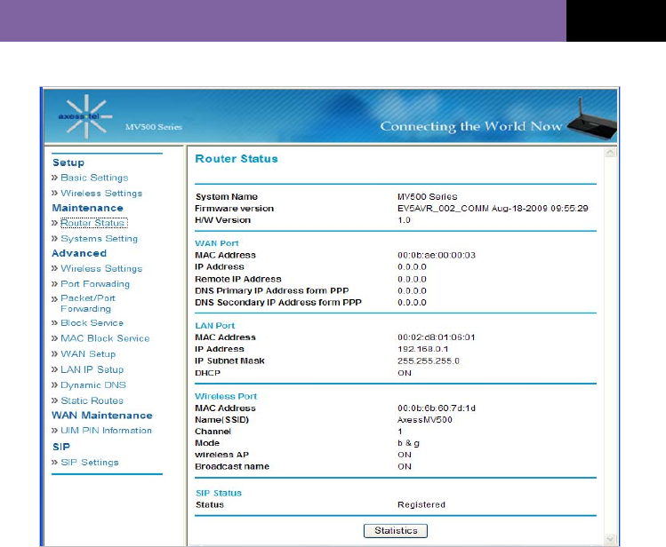
Maintenance: Router Status
Clicking on the header of the “Router Status” tab will take you to the “Router
Status” header page. A quick description of the functions can be found here.
IP Address
The “IP address” is the internal IP address of the Modem. The default IP
address is “192.168.0.1”. To access the web-based Advanced User Interface,
type this IP address into the address bar of your browser. This address can be
changed, if necessary.
Subnet Mask
This is a unique, advanced feature of your Axesstel Modem. It is possible to
change the subnet mask, if necessary. Do NOT make changes to the subnet
mask unless you have a specific reason to do so. The default setting is
“255.255.255.0”.
On this page, you can see all settings associated with the Modem’s router
network functions. These functions include:
• Account Name and Firmware Version
• WAN Port: MAC Address, IP Address, DHCP choice, IP Subnet Mask
and Domain Name Server Address
• LAN Port: MAC Address, IP Address, DHCP choice and IP Subnet Mask
• Wireless Port *: SSID, Region, Channel, Mode, Wireless AP status
(ON/OFF) and Broadcast Name status (ON/OFF)
• SIP Status: Showing the SIP registration status. If SIP is not registered,
“No Service” is displayed.
Click the button “Show Statistic” to see a graphic display of the router
performance.
MV500V SERIES (VER. STD 0.6)
30
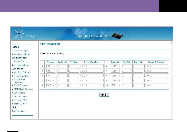
Port Forwarding
Clicking on the “Port Forwarding” sub-heading in the “Advanced” list will take you
to the “Port Forwarding” page. “Port Forwarding” allows you to route incoming
(Internet) calls for services such as a web server (port 80), FTP server (Port 21),
or other applications through your router to your internal network. Because your
internal computers are protected by a firewall, computers outside your network
(other computers connected to the Internet) cannot “see” or reach your computers.
A list of common applications has been provided in case you need to configure
the “Port Forwarding” function for a specific application. If you do, contact the
application vendor to find out which port settings you need.
MV500V SERIES (VER. STD 0.6)
31
Note: This advanced feature should be employed only by technically skilled users.
Enable Port Forwarding
To activate Port Forwarding, check the “Enable Port Forwarding” box.
Entering Settings into Port Forwarding
To enter settings into Port Forwarding, first select the appropriate service from
the “Protocol” drop-down box. You will see a list of common applications (FTP,
HTTP, Net-Meeting, and more). Select an application, enter the IP address and
port number for your internal server into the provided spaces, and click “Apply”.
Note: Opening ports in your firewall can pose a security risk. You can enable
and disable settings very quickly. It is recommended that you disable these
settings when you are not using a specific application.
Packet/Port Forwarding
This feature helps forward a Packet from a specific port to a specific host in your
MV500V SERIES (VER. STD 0.6)
32
LAN by changing the port number.
Note: This advanced feature should be employed only by technically skilled users.
Enable Packet/Port Forwarding
To activate this feature, check the “Enable Packet/Port Forwarding” box.
Block Services
Your Modem can be configured to restrict access to the Internet, email or other
network services at specific days and times. Restrictions can be set for a single
computer, a range of computers or multiple computers.
For example, to restrict Internet access for a single computer, enter the IP
address of the computer you wish to restrict access to in the IP field. Next, enter
“80” in both port fields. Select “Block”.
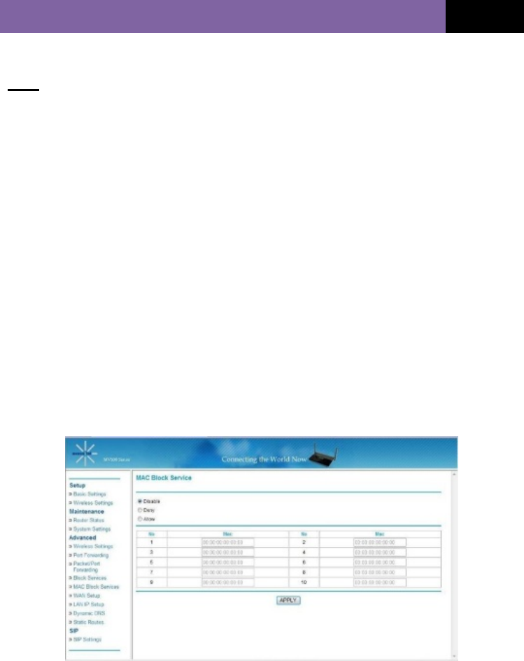
MAC Block Services
The MAC address filter is a powerful security feature that allows you to specify
which computers are allowed on your network. Any computer attempting to
access your network must be specified in the filter list or it will be denied access.
When you enable this feature, you must enter the MAC address of each client
(computer) on your network in order to allow network access to each.
MV500V SERIES (VER. STD 0.6)
33
MAC Services Blocking can be set in three modes.
• Disable. In this mode, there are no restrictions on any devices
connected to the Modem, whether through Wi-Fi or Ethernet ports
• Deny. In this mode, the service table shows the client MAC address
being blocked by the Modem.
• Allow. In this mode, the service table shows the client MAC address
allowed by the Modem.
To modify the service table (add, change address or remove clients), enter the
correct value and click “Apply”.
Note: You will not be able to delete the MAC address of the computer you are
using to access the Router’s administrative functions.
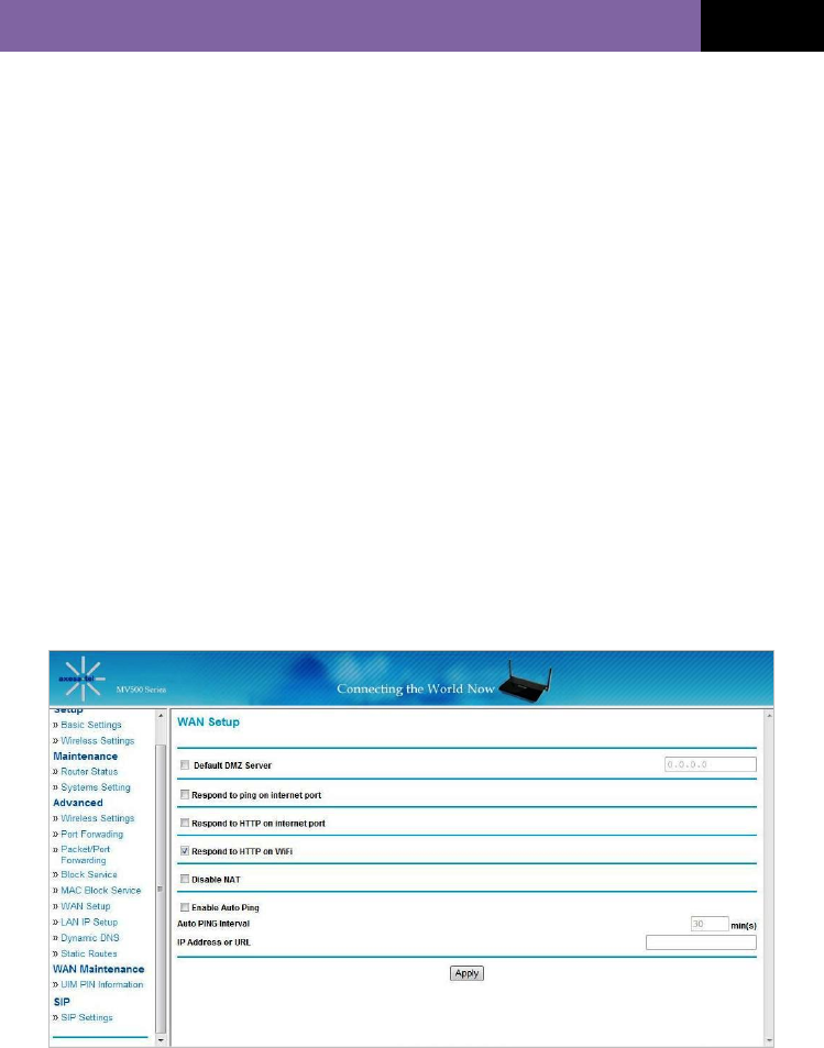
WAN Setup
Clicking on the “WAN Setup” sub-heading in the “Advanced” list will take you to
the “WAN Setup” page. This is where you can enable or disable the Modem’s
DMZ, Internet Ping, and HTTP-related items.

MV500V SERIES (VER. STD 0.6)
34
Enabling the Modem’s Demilitarized Zone (DMZ)
The DMZ feature allows you to specify one computer on your internal network
to be placed outside the firewall. This may be necessary if the firewall is
causing problems with a game, video conferencing, or other application. Use
this feature on a temporary basis. The computer in the DMZ is NOT protected
from hacker attacks.
WAN Ping Blocking
Computer hackers use what is known as “pinging” to find potential victims on
the Internet. By pinging a specific IP address and receiving a response, a
hacker can determine that something of interest might be at that IP address.
You can set your Modem so it will not respond to a hacker’s ICMP ping,
increasing the level of security provided by your Modem.
If it is necessary to turn on the ping response, select “Respond to Ping on
Internet Port” and click “Apply”. The Modem will respond to an ICMP ping.
Respond to HTTP on Internet Port
You can access Web GUI through WAN by clicking the “Respond to HTTP on
Internet Port” box. The Modem will respond to an HTTP ping.
Respond to HTTP on Wi-Fi
You can access Web GUI through Wi-Fi mode by clicking the “Respond to
HTTP on Wi-Fi” box. The factory default setting is ”Off”.
Enable Auto Ping
Regular pinging between a base transceiver station (BTS) and your Modem is

MV500V SERIES (VER. STD 0.6)
35
necessary to maintain an IP session connection. To turn on this feature, check
the “Enable Auto Ping” box and enter into the “IP Address or URL” box the
Destination IP information of the equipment that will be sending the pings.
LAN IP Setup
Clicking on the header of the “LAN IP Setup” tab will take you to its header page.
LAN TCP/IP Setup
All settings for the internal LAN setup of the Router can be viewed and changed
here.
IP Address: The “IP address” is the internal IP address of the Modem.
The default IP address is “192.168.2.1”. To access the Web Manager User
Interface, type this IP address into the address bar of your browser. This
address can be changed, if necessary. To change the IP address, type in
the new IP address and click “Apply”. The IP address you choose should
be a non-routable IP.
Examples of a non-routable IP are:
192.168.x.x (where x is anything between 0 and 255), and10.x.x.x (where x is
MV500V SERIES (VER. STD 0.6)
36
anything between 0 and 255).
Subnet Mask: There is no need to change the subnet mask. This is a unique,
advanced feature of your Modem. It is possible to change the subnet mask,
if necessary. Do NOT make changes to the subnet mask unless you have a
specific reason to do so. The default setting is “255.255.255.0”.
Use Router as DHCP Server
The DHCP server function makes setting up a network very easy by
assigning IP addresses to each computer on the network automatically. The
DHCP server can be turned OFF, if necessary. To do so, you must manually
set a static IP address for each computer on your network. To turn off the
DHCP server, de-select “Use Router As DHCP Server” and click “Apply”.
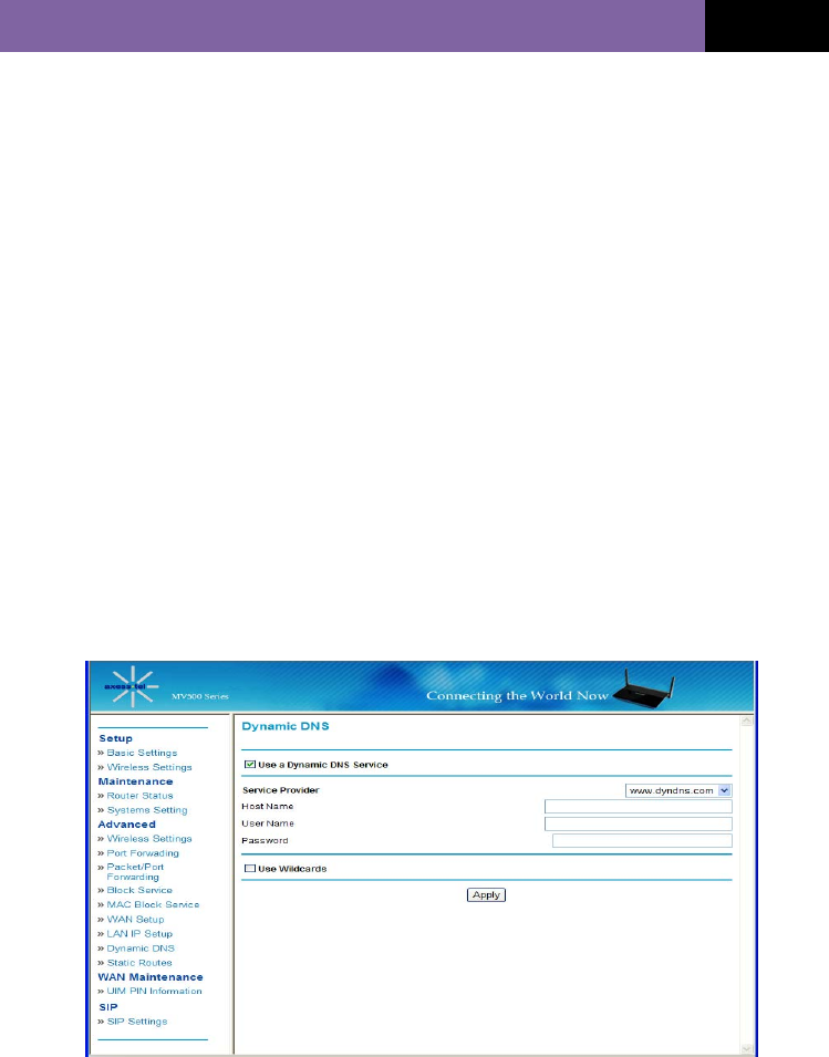
Dynamic DNS
Dynamic DNS (Domain Name Service) is a method for Dynamic IP users to notify
a domain name server to change, in real time (ad-hoc) the active DNS
configuration of its configured hostnames, addresses, or other information stored
in DNS. Your Modem supports Dynamic DNS.

MV500V SERIES (VER. STD 0.6)
37
To use Dynamic DNS, check the “Use a Dynamic DNS Service” box and
complete the following items.
Service Provider: Select the appropriate Service Provider from the drop-
down menu and input the Host Name, User Name, and your Password.
This information should be the same information that you registered with
your Dynamic DNS service provider.
Use Wildcards: Click “Use Wildcards” to enable wildcards for this host
or keep the box unchecked to disable wildcards for this host. The wildcard
alias *.yourhost.ourdomain.ext is the same address as
yourhost.ourdomain.ext.
Static Route
A static IP address connection type is less common than other connection types.
If your ISP uses static IP addressing, you will need your IP address, subnet mask
and ISP gateway address. This information is available from your ISP or on the
paperwork that your ISP gave you. Type in your information and click “Apply”.
IP Address: Provided by your ISP. Enter your IP address here.
Subnet Mask: Provided by your ISP. Enter your subnet mask here.
ISP Gateway Address: Provided by your ISP. Enter the ISP gateway address
here.
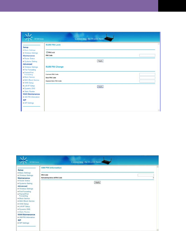
WAN Maintenance: UIM PIN Information
Note: This feature is applicable to RUIM version Modem only.
Setting a PIN code allows you to lock the Modem’s UIM card, protecting your
MV500V SERIES (VER. STD 0.6)
38
Modem against unauthorized use. Check the “PIN Lock” box to activate this
feature.
RUIM PIN Lock: Create a 4-digit PIN code, enter it into the “PIN Code”
column box, and click “Apply”.
Once you set a RUIM PIN code, your Modem will ask you to enter this code
into the Web GUI’s UIM PIN Information screen. You will see the screen shown
below when your Modem boots up for internet use.
Enter your PIN Code in the column box and click “Apply”..
MV500V SERIES (VER. STD 0.6)
39
RUIM PIN Change: To change your PIN Lock code:
1. Enter your current 4-digit PIN Code in the “Current PIN Code” box.
2. Enter a new 4-digit PIN Code in the “New PIN Code” box.
3. Re-enter your new PIN Code in the “Repeat New PIN Code” box.
4. Click the “Apply” button
Note: If you forget or lose your PIN code and enter an incorrect PIN 5 times in
succession, you must enter the PUK code to unlock the Modem. Contact your
service provider for help.
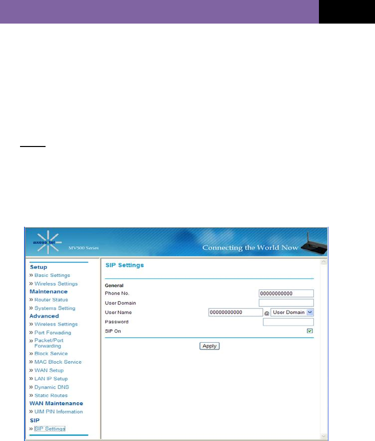
SIP (VoIP Call Settings)
SIP Settings
Phone No.: The default phone number that appears in this box is based on
your ISP’s setting value. If you do not see a number in the Phone No. box on

MV500V SERIES (VER. STD 0.6)
40
your screen, contact your ISP and ask for the correct number..
User Domain: The default User Domain that appears in this box is based on
your ISP’s setting value. If you do not see a User Domain from the box, contact
your ISP and ask for the correct User Domain.
User Name: The default User Name that appears in this box is based on your
ISP’s setting value. If you do not see a User Name from the box, contact your
ISP and ask for the correct User Name.
Password: The default Password that appears in this box is based on your
ISP’s setting value. If you do not see a Password from the box, contact your ISP
and ask for the correct Password.
SIP On: Check the box to turn the VoIP feature on. Uncheck the box to turn it
off.
MV500V SERIES (VER. STD 0.6)
41
VoIP CALL FUNCTIONS
Note: Your Modem’s CDMA and VoIP accounts must be properly
activated for VoIP call functions to work.
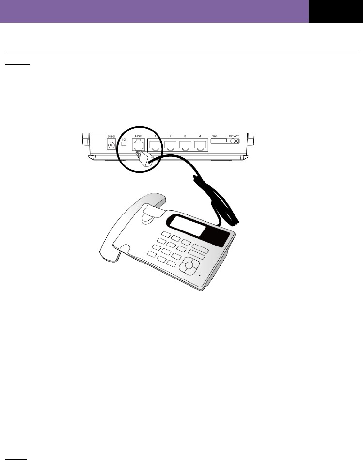
To setup your wired, landline phone for VoIP calling, plug the phone’s RJ-11 cable
into the “Line” port on your Modem as shown below.
PLACING VOICE CALLS
1. Turn on the Modem.
2. Lift the handset from your phone.
3. When you hear a dial tone, use the phone’s
numeric keypad to dial the desired phone number, and then quickly press the
<#> button to launch the call.
4. Wait several seconds while the Modem places the call.
Note: Be sure to press <#> immediately after entering a phone number. Pressing

MV500V SERIES (VER. STD 0.6)
42
<#> activates the modem to place the call..This sequence could be varying up to
your service provider’s dial plan and Digit Map.
5. When your call is answered, begin the conversation.
6. To disconnect a call, replace the handset on the phone.
RECEIVING VOICE CALLS
The telephone(s) connected to the Modem ring when receiving an incoming
call.
1. Lift the telephone’s handset to answer a call.
2. To disconnect a call, replace the handset on the phone.
Note 1: For the phone to ring, its ringer must be enabled.
Note 2: To answer an incoming call while you are holding the receiver, press any
key on the phone’s numeric keypad.
CALL WAITING
The Call Waiting feature alerts you to a call that’s coming in while you are
talking on the phone with someone else. Contact your service provider to
activate or deactivate Call Waiting feature.
1. When Call Waiting is activated, a beep in your earpiece alerts you to a second
incoming call.
2. Press the hook quickly to answer the second call.
3. Press the hook again to return to the first call.

MV500V SERIES (VER. STD 0.6)
43
THREE-WAY CALLING
Your Modem supports Three-Way Calling which enables you to set up a
phone conversation between yourself and two additional phone users..
Contact your service provider to activate or deactivate Three-way Calling
service. To initiate a three-way call:
1. Place the first call.
2. When the first call is answered, press the phone hook quickly and place the
second call.
3. When the second call is answered, lightly press the hook to start your three-
way call.
CALL HOLDING
In the event of Call Waiting, the Call Holding feature allows you to put an active
call on hold while you answer a second incoming call by pressing Hook Switch on
the phone.
Note: The Call Holding features could not be available according to your service
provider’s network condition.
VOICE MAIL SERVICE
When a voice message is received, your Modem’s “Connect” LED blinks in Blue
along with single time indicating sound. After you check your voice messages, the
LED turns off. Contact your Service Provider to activate or deactivate voice mail
service.
Clearing Voice Mail:
After calling the voice mail access number, please follow the instruction to set-up,
listen and delete voice messages.

MV500V SERIES (VER. STD 0.6)
44
SETTING CALLER ID
If the phone connected to your Modem is Caller ID-enabled, you can set the
Modem to display a caller’s identification number or name on your phone’s
LCD display. To set Caller ID through the Modem:
1. Lift the handset from your phone.
2. Press <*><*><2><1><0><#> to disable Caller ID. [Disable or Enable? Why
explaining disabling first?]
3. Press <*><*><2><1><1><#> to enable DTMF Standard Type.
4. Press <*><*><2><1><2><#> to enable FSK (Bellcore) Type.
Note: The default setting for Caller ID is DTMF Type.

MV500V SERIES (VER. STD 0.6)
45
TROUBLESHOOTING
Problem:
• I am unable to connect to the Internet. The Modem’s “Signal” light is
on and the “Connect” light is off.
Solution:
If you cannot connect to the Internet while the “Signal” light is on and the
“Connect” light is off, it could be that your connection type may not match the
ISP’s connection.
• If you have a “static IP address” connection, your ISP must assign
you the IP address, subnet mask and gateway address. Please refer to the
section entitled “Alternate Setup Method” for details on changing this
setting.
• If you are still unable to access the Internet after verifying these
settings, please contact your Service Provider Technical Support.
Problem:
• I am unable to connect to the Internet. The Modem’s “Signal” light is
on and the “Connect” light is on.
Solution:
If the “Signal” light is on and the “Connect” light is on but you are unable to
access the Internet, it could be that third-party firewall software was installed
on the computer attempting to access the Internet. Examples of third-party
firewall software are ZoneAlarm, BlackICE PC Protection, McAfee Personal
Firewall and Norton Personal Firewall.
If you do have firewall software installed on your computer, please make sure
that you properly configured it. You can determine if the firewall software is
preventing Internet access by temporarily turning it off. If the firewall is
disabled and Internet access works properly, you will need to change the
firewall settings to function properly when it is turned on.
Please refer to the manual provided by the publisher of your firewall software
for instructions on configuring the firewall to allow Internet access.

MV500V SERIES (VER. STD 0.6)
46
If you are still unable to access the Internet after disabling any firewall
software, please contact your Service Provider Technical Support.
Problem:
I can’t connect to the Internet wirelessly from my computer but it works if I
use the Ethernet cable.
Solution:
If you are unable to connect to the Internet from a wireless computer,
please do the following:
1. Look at the lights on your Modem. Your Modem’s lights should be as
follows:
• The “Power” light should be on.
• The “Connected” light should be on and not blinking.
• The “WAN” light should be on or blinking.
2. Open your wireless utility software by clicking on the icon in the
system tray at the bottom, right-hand corner of your screen.
3. The exact window that opens will vary depending on the model of
wireless card you have. However, each utility should have a list of
“Available Networks” which are the wireless networks your Modem
can connect to.
Problem:
My wireless network performance is inconsistent.
Data transfer is sometimes slow.
Signal strength is poor.
I am having difficulty establishing and/or maintaining a Virtual Private
Network (VPN) connection.
Solution:
Because wireless technology is radio-based connectivity and throughput
performance between devices decreases as the distance between devices
increases. Signal degradation is also caused by obstructions such as walls

MV500V SERIES (VER. STD 0.6)
47
and metal appliances (metal is generally the worst culprit). As a result, the
typical indoor range of your wireless devices will be from 100 to 200 feet.
Note, too, that connection speed may decrease as you move farther away
from the Modem or network access point.
To determine if wireless issues are related to range, temporarily move your
computer, if possible, five to 10 feet away from the Modem.
Changing the Wireless Channel - Depending on local wireless traffic and
interference, switching the wireless channel of your network can improve
performance and reliability. Your Modem’s default channel is channel 11.
You may choose from several other channels, depending on your region
(see “Changing the Wireless Channel” on page 41 for instructions on how to
choose other channels).
Limiting the Wireless Transmit Rate - Limiting the wireless transmit rate can
help improve your network’s maximum wireless range and connection
stability. Most wireless cards have the ability to limit the transmission rate.
To change this property, go to the Windows Control Panel, open “Network
Connections” and double-click on your wireless card’s connection. In the
“Properties” dialog, select the “Configure” button on the “General” tab
(Windows 98 users will have to select the wireless card in the list box and
then click “Properties”). Choose the “Advanced” tab and select the rate
property. Wireless client cards are usually set to automatically adjust the
wireless transmit rate for you, but doing so can cause periodic disconnects
when the wireless signal is too weak. As a rule, slower transmission rates
are more stable.
Experiment with different connection rates until you find the best one for
your environment. Note that all available transmission rates should be
acceptable for browsing the Internet. For more assistance, see your
wireless card’s user manual.

MV500V SERIES (VER. STD 0.6)
48
Technical Specifications
CDMA Channel Bandwidth 1.23 MHz
RX/TX Frequency Range 450 MHz A block: RX 462.5 ~ 467.5Mhz / TX 452.5 ~ 457.5Mhz
450 MHz H block: RX 461.3 ~ 465.8Mhz / TX 451.3 ~ 455.8Mhz
450 MHz L block: RX 420.0 ~ 424.5Mhz / TX 410.0 ~ 414.5Mhz
800 MHz: RX 869.64 ~ 893.37 MHz / TX 824.64 ~ 848.37 MHz
1900 MHz: RX 1930 ~ 1990 MHz / TX 1850 ~ 1910 MHz
Wi-Fi Operating Frequency 2.4 GHz ~ 2.4835 GHz ISM band
VoIP Voice Interface 1 port (RJ-11)
External Appearance (mm) 127.50 (L) x 185.00 (W) x 36.10 (H)
Weight 435g (Gateway with battery)
Temperature of Operation -10 °C ~ +60 °C
Temperature of Storage -30 °C ~ +70 °C
Relative Humidity 5% ~ 90%
Adapter Input: AC 90~280 V 47~63 Hz
Battery
(Li-Ion Rechargeable Battery
2100 mAh)
Standby Time 4 Hrs
Operation Time 150 Min
VoIP Talk Time 2 Hrs
Charging Time 8 Hrs
Wall Mounting Yes
Note: Battery Operation Time mentioned above may be varying up to network condition.
MV500V SERIES (VER. STD 0.6)
49
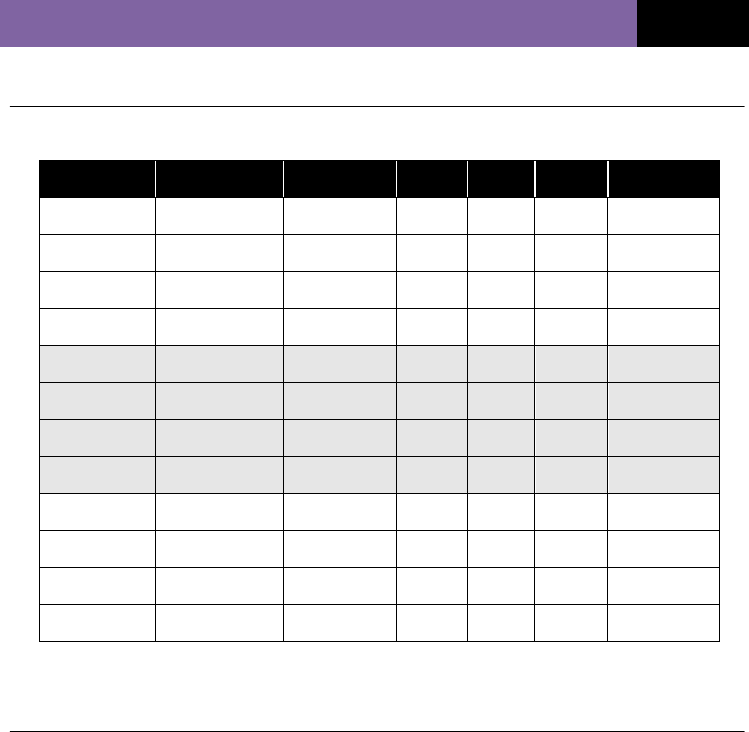
Modem Functions by Model
Certifications
CE: MV510VR
FCC: TBD
RoHS: MV510VR
Model Frequency Ethernet Wi-Fi VoIP RUIM 1x Voice
MV510 450 O O
- O -
MV520 800 O O
- O -
MV530 1900 O O
- O -
MV540 800/1900 O O
- O -
MV510S 450 O O - O O
MV520S 800 O O - O O
MV530S 1900 O O - O O
MV540S 800/1900 O O - O O
MV510V 450 O O O O -
MV520V 800 O O O O -
MV530V 1900 O O O O -
MV540V 800/1900 O O O O -

MV500V SERIES (VER. STD 0.6)
50
Appendix A: Glossary
1X One Times Radio Transmission Technology (the “one times” refers to the
frequency spectrum). Supports Internet connections with data rates up to
153 Kbps. Actual speed depends on network conditions. Compare to 1x
EV-DO.
1x-EVDO A high speed standard for cellular packet data communications.
Rev. A supports Internet connections with data rates up to 3.1 Mbps (on
the downlink from the network) and 1.8 Mbps (on the uplink to the
network).
Rev. 0 supports Internet connections with data rates up to 2.4 Mbps (on
the downlink from the network) and 153 Kbps (on the uplink to the
network).
Average data rates: for Rev. A, 600–1300 Kbps (on downlink) and 300–
400 Kbps (on uplink); for Rev. 0, 400–700 Kbps (on downlink) and 40-80
Kbps (on uplink).
Actual speed depends on network conditions. Compare to 1X.
bps Bits Per Second—Actual data speed over a transmission medium.
CDMA Code Division Multiple Access—A wideband spread spectrum technique
used in digital cellular, personal communications services and other
wireless networks. Wide channels (1.25 MHz) are obtained through
spread spectrum transmissions, allowing many active users to share the
same channel. Each user is assigned a unique digital code which
differentiates individual conversations on the same channel.
CDMA 1X Also known as 1X, this is a high-speed standard for CDMA cellular
communications.
Dormant The packet data connection keeps the logical PPP session open while
the underlying physical link (radio channel) is released. When traffic
resumes, a radio channel is reacquired and the original PPP session
also resumes.

MV500V SERIES (VER. STD 0.6)
51
DNS Domain Name Service
ESN Electronic Serial Number—The unique first-generation serial number
assigned to the Modem for cellular network use. Compare to MEID.
FCC Federal Communications Commission. The U.S. federal agency that is
responsible for interstate and foreign communications. The FCC
regulates commercial and private radio spectrum management, sets
rates for communications services, determines standards for equipment
and controls broadcast licensing. Consult www.fcc.gov.
Firmware Software stored in flash memory. These essential programs (CDMA
Firmware and Router Firmware) remain even when the system is turned
off. Firmware is easier to change than hardware but more permanent
than software stored on disks.
Host 1. A computer that uses a Modem or similar device to answer a calling
computer.
2. A source or destination in the communication network.
3. A computer that contains data or files to be accessed by client
computers. Also known as a server.
IS Interim Standard—After receiving industry consensus, the TIA forwards
the standard to ANSI for approval.
IS-95 The standard for CDMA.
Kbps Kilobits per second—Actually 1000, not 1024, as used in computer
memory size measurements of kilobytes.
LAN Local Area Network.
LED Light Emitting Diode—A semiconductor diode that emits visible or
infrared light.
MEID Mobile Equipment Identifier—The unique second-generation serial
number assigned to the Modem for cellular network use. Compare to
ESN.
MHz Megahertz—One million cycles per second.
Mbps Megabits Per Second.

MV500V SERIES (VER. STD 0.6)
52
Packet A short, fixed-length block of data including a header that is transmitted
as a unit in a communication network.
PCS Personal Communications Services—A cellular communication
infrastructure that uses a different frequency range than AMPS.
Roaming The ability for a cellular subscriber to utilize voice, data and other cellular
services of a visited network when traveling outside the geographical
coverage area of the subscriber’s home network.
RUIM Removable User Identity Module. Allows CDMA users to change phones
and keep their phone numbers by simply swapping the cards.
SMS Short Message Services—A feature that allows users of a wireless
device on a wireless network to receive or transmit short, electronic
alphanumeric messages (usually up to 160 characters).
System tray Typically located in the lower-right corner of your screen.
SIP Session Initiation Protocol
TIA Telecommunications Industry Association—A standards-setting trade
organization whose members provide communications and information
technology products, systems, distribution services and professional
services in the United States and around the world. Consult
www.tiaonline.org.
VPN Virtual Private Network
VoIP Voice Over Internet Protocol

MV500V SERIES (VER. STD 0.6)
53
<15.105>
NOTE: This equipment has been tested and found to comply with the limits for a Class B
digital device, pursuant to part 15 of the FCC Rules.
These limits are designed to provide reasonable protection against harmful interference in
a residential installation. This equipment generates, uses and can radiate radio frequency
energy and, if not installed and used in accordance with the instructions, may cause
harmful interference to radio communications. However, there is no guarantee that
interference will not occur in a particular installation.
If this equipment does cause harmful interference to radio or television reception,
which can be determined by turning the equipment off and on, the user is encouraged to
try to correct the interference by one or more of the following measures:
—Reorient or relocate the receiving antenna.
—Increase the separation between the equipment and receiver.
— Connect the equipment into an outlet on a circuit different from
that to which the receiver is connected.
—Consult the dealer or an experienced radio/TV technician for help.
Caution the user that changes or modifications not expressly approved by the party
responsible for compliance could void the user’s authority to operate the equipment.

MV500V SERIES (VER. STD 0.6)
54
FCC ID: PH7MV540V
Warning: Exposure to Radio Frequency Radiation The radiated
output power of this device is far below the FCC radio frequency
exposure limits. Nevertheless, the device should be used in such
a manner that the potential for human contact during normal
operation is minimized. In order to avoid the possibility of
exceeding the FCC radio frequency exposure limits, human
proximity to the antenna should not be less than 20 cm during
normal operation. The gain of the antenna for Cellular band must
not exceed 0.28 dBi.
The gain of the antenna for PCS band must not exceed 2.66 dBi.

MV500V SERIES (VER. STD 0.6)
55