Axesstel TG130F GSM GPRS Quad Band Fixed Wireless Terminal User Manual
Axesstel Inc GSM GPRS Quad Band Fixed Wireless Terminal Users Manual
UserManual.wiki
>
Axesstel
>
TG130F User Manual
Users Manual
Navigation menu
Upload a User Manual
Namespaces
Wiki Guide
HTML
PDF
Info
Views
User Manual
Discussion / Help
Navigation
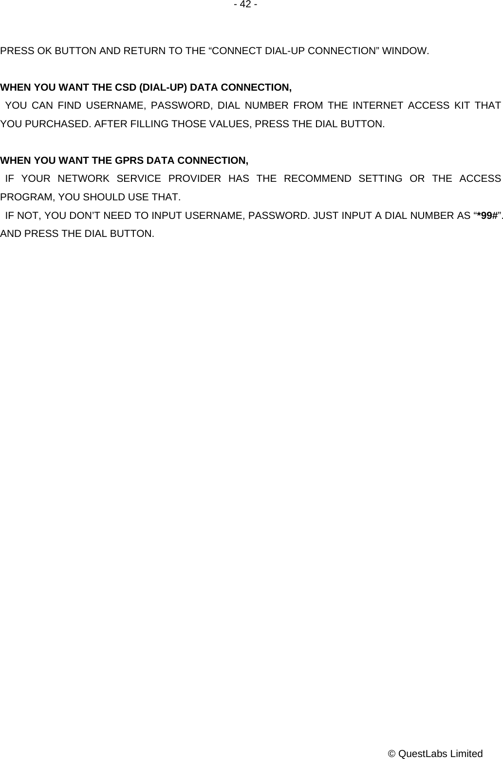
![- 6 - © QuestLabs Limited 1. Installation guide 1.1. Front, Side and Rear View of TG130 [FRONT VIEW] [SIDE VIEW]](https://usermanual.wiki/Axesstel/TG130F/User-Guide-1041396-Page-6.png)
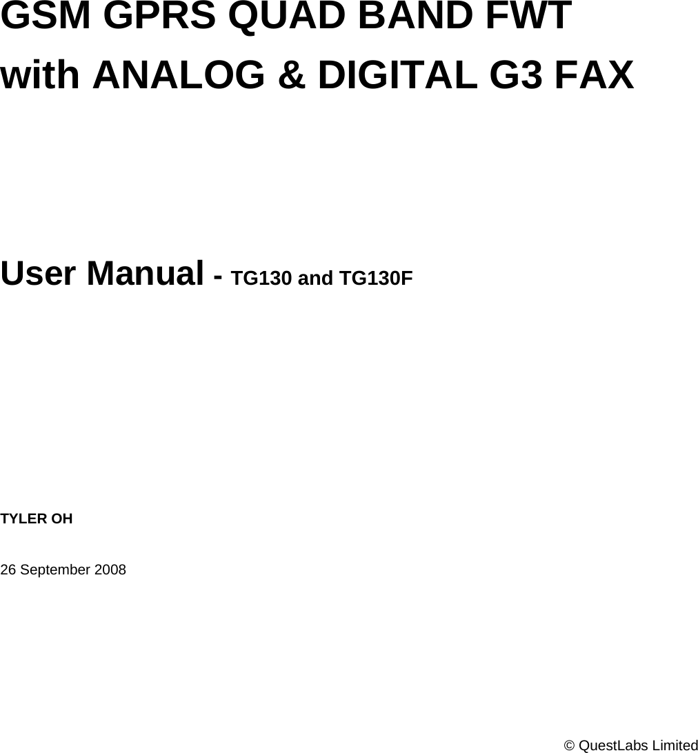
![- 7 - © QuestLabs Limited [REAR VIEW] 1.2. Checking the components Check to make sure that you have all the parts shown below after opening the package. If any piece is missing or broken, please call your agent or customer service. 1. MAIN UNIT 2. ANTENNA AND THE CABLE WITH THEIR SUPPORT (YOU SHOULD COUPLE THE ANTENNA IN THEIR SUPPORT) 3. DC POWER ADAPTER 4. FOUR SUPPORTS TO HEAP SEVERAL UNITS. 5 .LI-ION BACKUP BATTERY 6. BASE TO SUSTAIN AN UNIT IN VERTICAL POSITION.](https://usermanual.wiki/Axesstel/TG130F/User-Guide-1041396-Page-7.png)
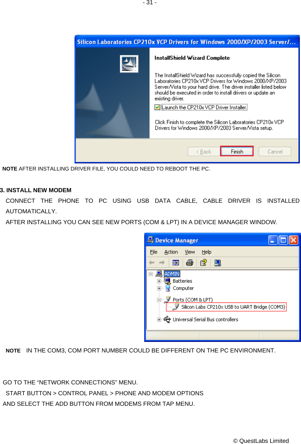
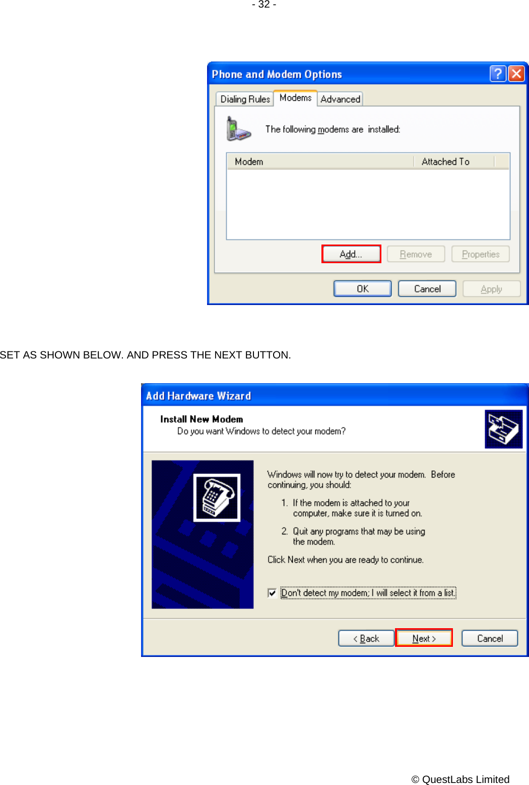
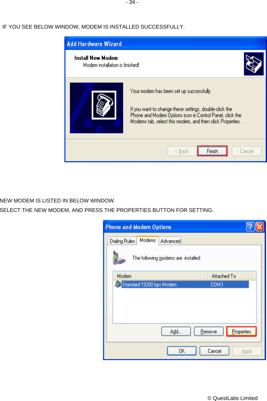
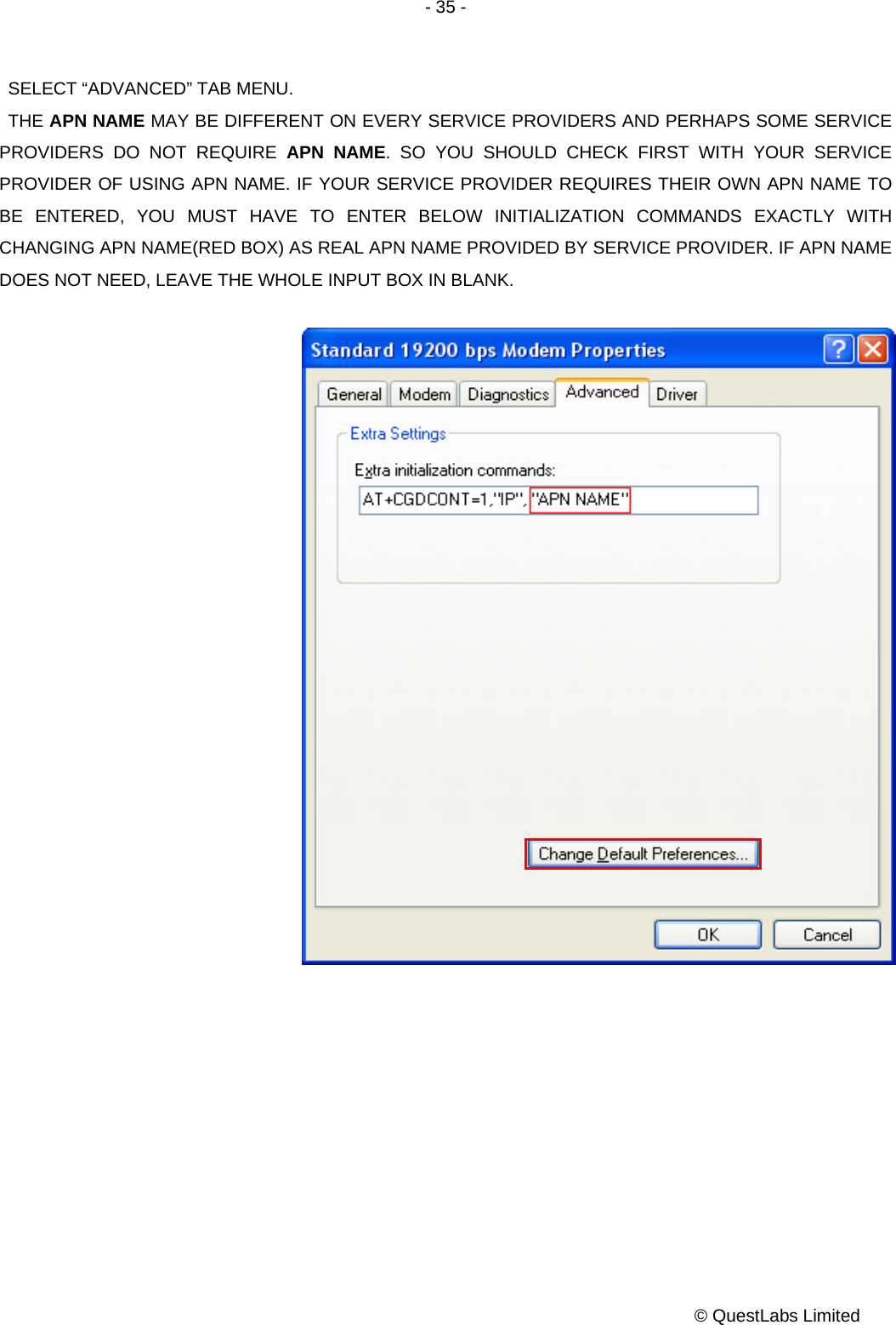
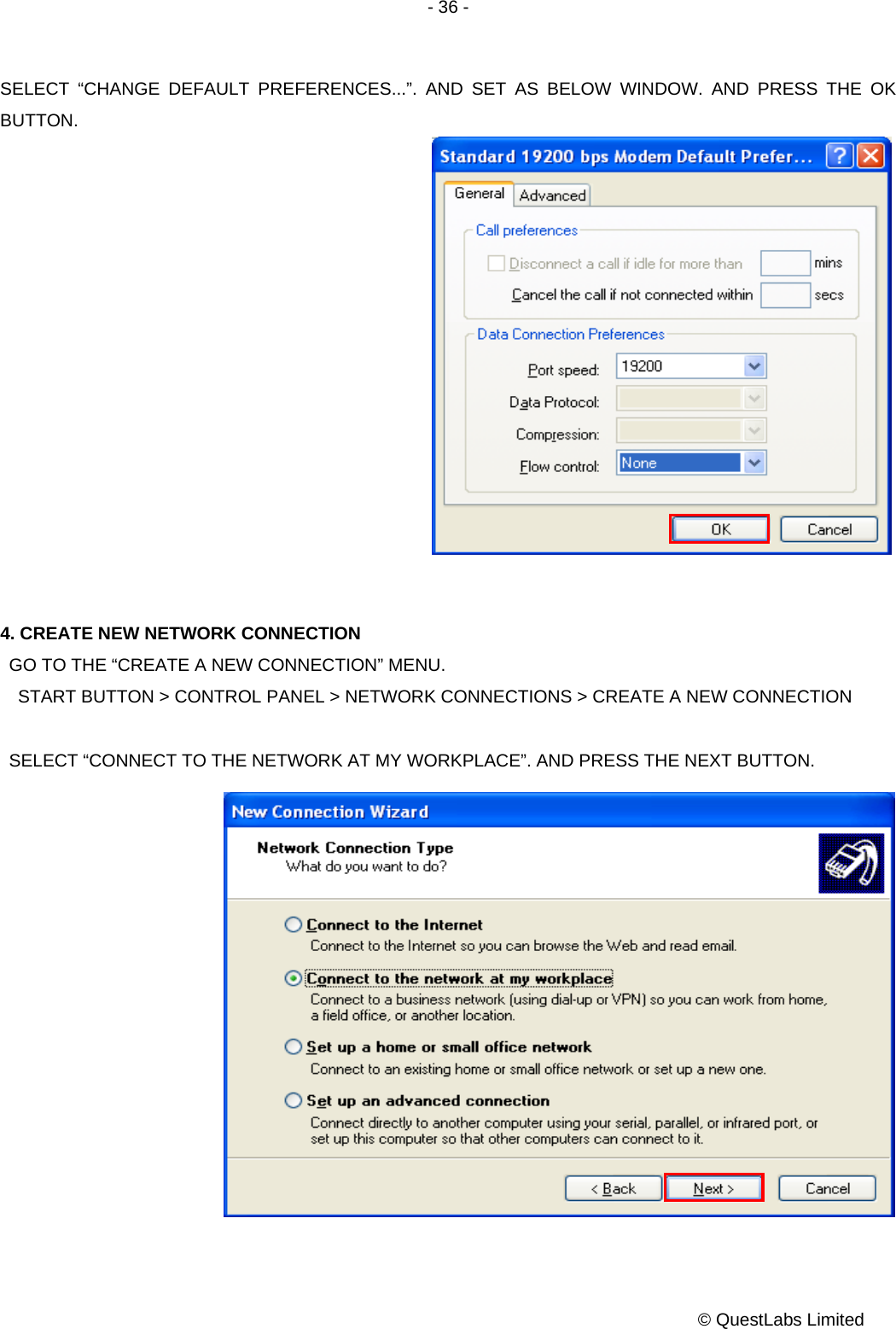
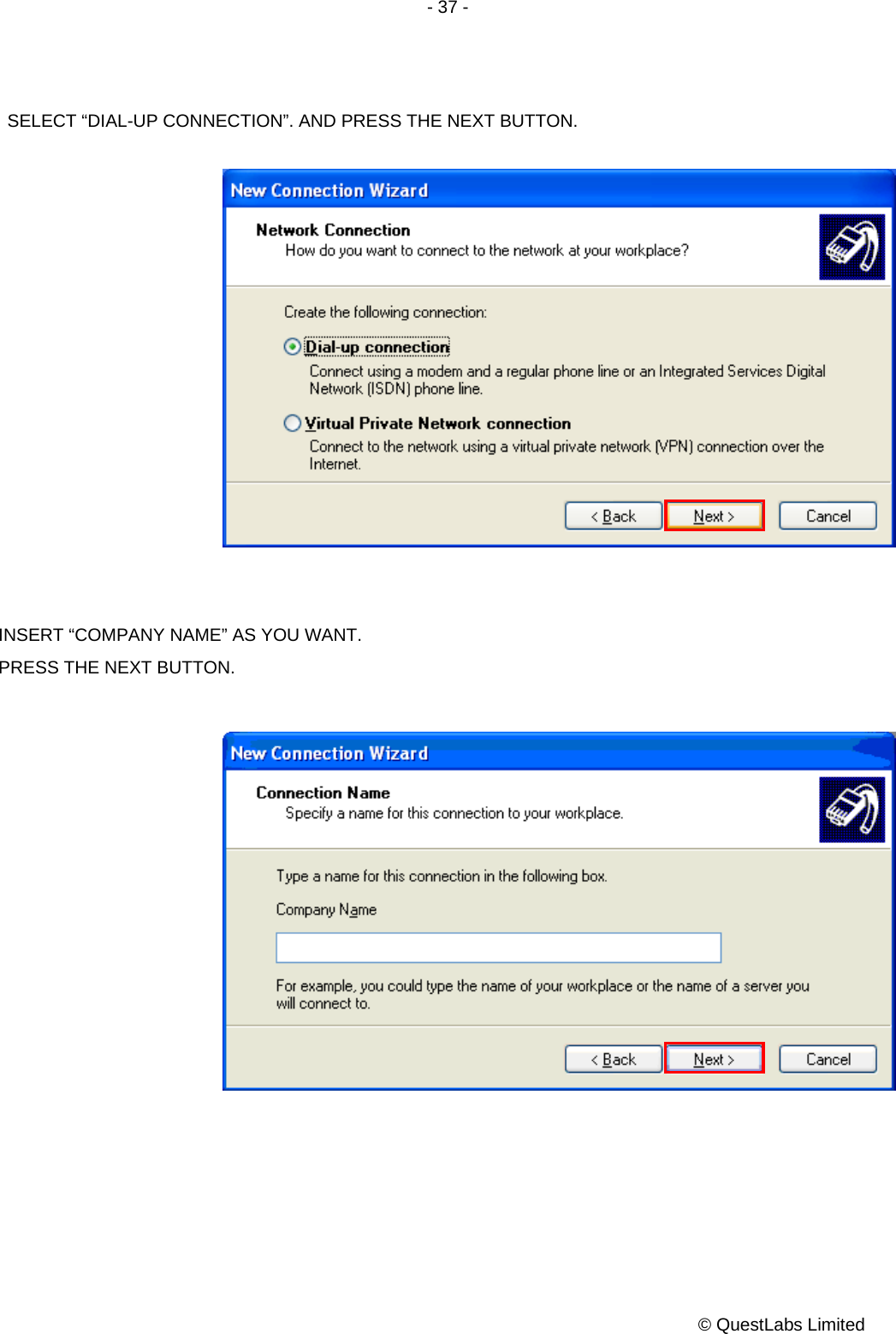
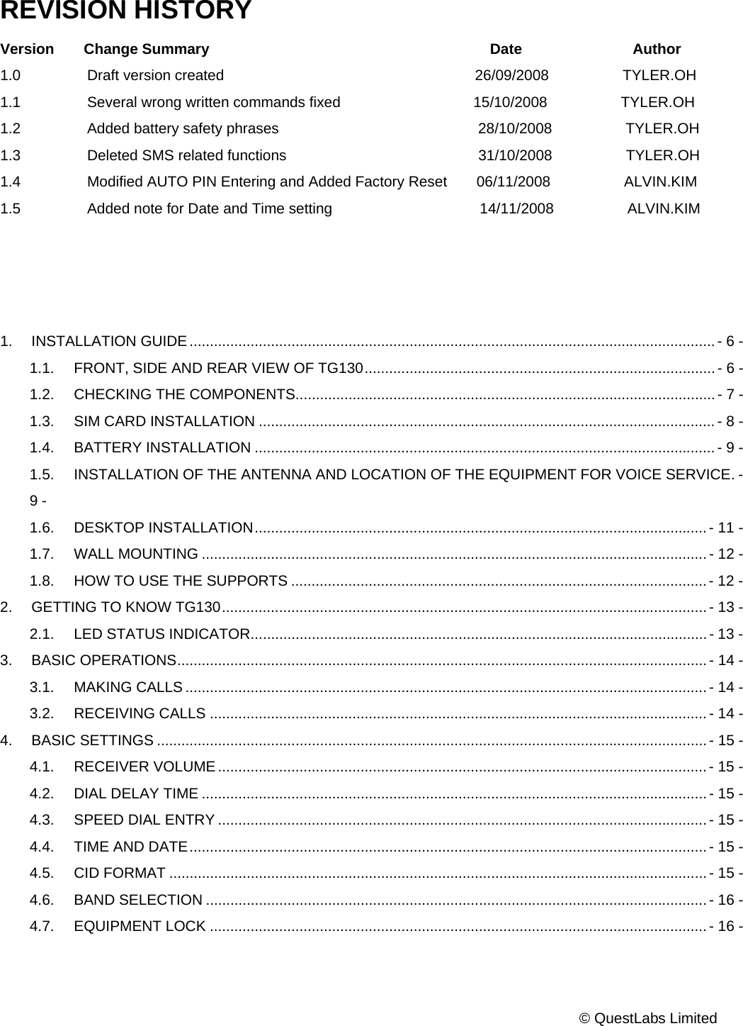
![- 33 - © QuestLabs Limited SELECT “[STANDARD MODEM TYPES]” AND “STANDARD 19200 BPS MODEM”. AND PRESS THE NEXT BUTTON. SELECT A APPROPRIATE PORT THAT YOU HAVE SELECTED. THIS MAY TAKE SEVERAL MINUTES. NOTE IN THE COM3, COM PORT NUMBER COULD BE DIFFERENT ON THE PC ENVIRONMENT.](https://usermanual.wiki/Axesstel/TG130F/User-Guide-1041396-Page-33.png)