Axesstel TG130F GSM GPRS Quad Band Fixed Wireless Terminal User Manual
Axesstel Inc GSM GPRS Quad Band Fixed Wireless Terminal Users Manual
Axesstel >
Users Manual
© QuestLabs Limited
GSM GPRS QUAD BAND FWT
with ANALOG & DIGITAL G3 FAX
User Manual - TG130 and TG130F
TYLER OH
26 September 2008
© QuestLabs Limited
REVISION HISTORY
Version Change Summary Date Author
1.0 Draft version created 26/09/2008 TYLER.OH
1.1 Several wrong written commands fixed 15/10/2008 TYLER.OH
1.2 Added battery safety phrases 28/10/2008 TYLER.OH
1.3 Deleted SMS related functions 31/10/2008 TYLER.OH
1.4 Modified AUTO PIN Entering and Added Factory Reset 06/11/2008 ALVIN.KIM
1.5 Added note for Date and Time setting 14/11/2008 ALVIN.KIM
1. INSTALLATION GUIDE ................................................................................................................................. - 6 -
1.1. FRONT, SIDE AND REAR VIEW OF TG130 ...................................................................................... - 6 -
1.2. CHECKING THE COMPONENTS ....................................................................................................... - 7 -
1.3. SIM CARD INSTALLATION ................................................................................................................ - 8 -
1.4. BATTERY INSTALLATION ................................................................................................................. - 9 -
1.5. INSTALLATION OF THE ANTENNA AND LOCATION OF THE EQUIPMENT FOR VOICE SERVICE . -
9 -
1.6. DESKTOP INSTALLATION ............................................................................................................... - 11 -
1.7. WALL MOUNTING ............................................................................................................................ - 12 -
1.8. HOW TO USE THE SUPPORTS ...................................................................................................... - 12 -
2. GETTING TO KNOW TG130 ....................................................................................................................... - 13 -
2.1. LED STATUS INDICATOR ................................................................................................................ - 13 -
3. BASIC OPERATIONS .................................................................................................................................. - 14 -
3.1. MAKING CALLS ................................................................................................................................ - 14 -
3.2. RECEIVING CALLS .......................................................................................................................... - 14 -
4. BASIC SETTINGS ....................................................................................................................................... - 15 -
4.1. RECEIVER VOLUME ........................................................................................................................ - 15 -
4.2. DIAL DELAY TIME ............................................................................................................................ - 15 -
4.3. SPEED DIAL ENTRY ........................................................................................................................ - 15 -
4.4. TIME AND DATE ............................................................................................................................... - 15 -
4.5. CID FORMAT .................................................................................................................................... - 15 -
4.6. BAND SELECTION ........................................................................................................................... - 16 -
4.7. EQUIPMENT LOCK .......................................................................................................................... - 16 -
© QuestLabs Limited
4.8. POLARITY REVERSE ....................................................................................................................... - 16 -
4.9. LOOP CURRENT DISCONNECT ..................................................................................................... - 16 -
4.10. DTMF TONE GENERATION ......................................................................................................... - 16 -
4.11. FACTORY RESET ......................................................................................................................... - 17 -
4.12. PIN LOCK ...................................................................................................................................... - 17 -
4.13. AUTOMATIC PIN ENTERING ....................................................................................................... - 17 -
5. SUPPLEMENTARY SERVICE FEATURES ................................................................................................ - 18 -
5.1. CALL FORWARDING ........................................................................................................................ - 18 -
5.2. CALL BARRING ................................................................................................................................ - 19 -
5.3. CALL WAITING ................................................................................................................................. - 20 -
5.4. CALLER ID ........................................................................................................................................ - 21 -
6. DATA SERVICE FEATURES ...................................................................................................................... - 21 -
7. FAX SERVICE FEATURE ........................................................................................................................... - 21 -
7.1. ANALOG FAX .................................................................................................................................... - 21 -
7.2. DIGITAL FAX ..................................................................................................................................... - 22 -
8. GENERAL INFORMATION .......................................................................................................................... - 23 -
8.1. SPECIFICATIONS ............................................................................................................................. - 23 -
8.2. ADDITIONAL SAFETY INFORMATION ............................................................................................ - 23 -
8.3. GUARANTEE .................................................................................................................................... - 25 -
8.4. TROUBLESHOOTING ...................................................................................................................... - 29 -
9. CONFORMANCE STATEMENTS ............................................................................................................... - 29 -
APPENDIX A:……………………………………………………………………………………………………………..- 31 -
© QuestLabs Limited
- 4 -
Welcome to your TG130 / TG130F
TG130 is a Fixed Wireless Terminal designed to provide better wireless connectivity between wire telephone and
GSM 850/900/1800/1900 band network with high sensitivity to receive signal and large transmitting power to
expand extensively the effective coverage of GSM service.
Main function & features
- SIMPLE TO INSTALL AND EASY TO MAINTAIN
- COMPATIBLE TO MOST TELEPHONES, PBX
- BATTERY BACK UP DURING AC POWER OUTAGES
- PROVIDE REVERSAL POLARITY SIGNAL FOR METERING
- ADJUSTABLE RECEIVER VOLUME
- 3 LED DISPLAY (SIGNAL/MODE/POWER)
- 10 SPEED DIALS
- CALLER ID DISPLAY
- NETWORK BAND SELECTION
- CALL WAITING/FORWARDING/BARRING
- CONFERENCE CALL
- DATA COMMUNICATION (CSD/GPRS, DIGITAL FAX VIA CSD) USING DATA CABLE(OPTIONAL)
- ANALOG FAX (TG130F)
- 5 -
© QuestLabs Limited
For your safety
Here is important information for safe and efficient operation.
Please read this information before using your TG130.
For optimal performance, install this indoors. When specially used in an outdoor area, it may not work in below -10℃
or over 50℃.
Install TG130 on hard, flat surface for proper ventilation.
Avoid using TG130 in high temperature or near a source of fire or gas.
Avoid storing TG130 in cold areas.
Do not expose TG130 to moisture or dust.
Do not use TG130 in the hospital. It will interfere with medical electronic equipments such as a peace maker.
Do not use harsh chemicals, cleaning solvents to clean TG130. And wipe with a soft, clean, dry cloth to clean it.
Do not knock, drop, and shake TG130 to avoid breaking the case.
Use only the supplied or approved replacements
Do not use TG130 with a car battery.
Do not touch the antenna when TG130 is being used.
Do not use TG130 with a damaged antenna. Have your antenna replaced by a qualified technician immediately.
Use only the provided antenna. Do not use the provided antenna for any other purpose.
Use only the provided adapter. Do not use the provided adapter for any other purpose
If TG130 fails to work for any reason, do not attempt to disassemble.
Risk of explosion if battery is replaced by an incorrect type.
Dispose of used batteries according to the instructions.
- 6 -
© QuestLabs Limited
1. Installation guide
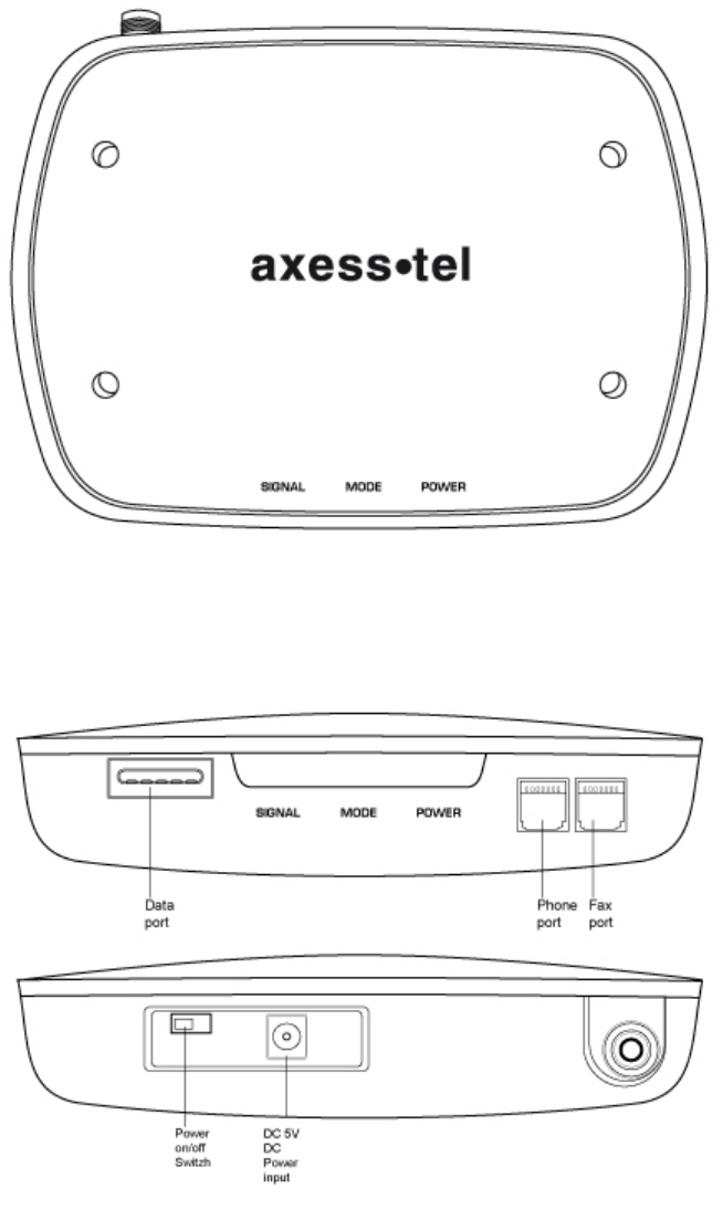
1.1. Front, Side and Rear View of TG130
[FRONT VIEW]
[SIDE VIEW]
- 7 -
© QuestLabs Limited
[REAR VIEW]
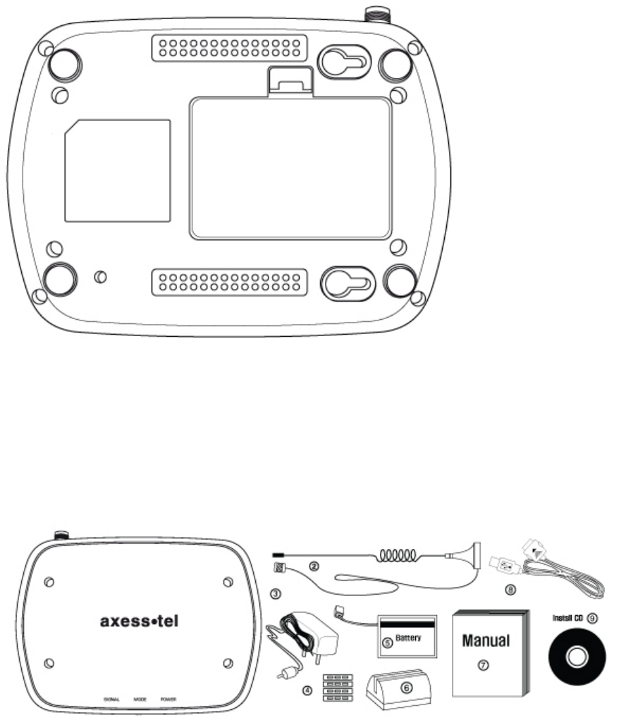
1.2. Checking the components
Check to make sure that you have all the parts shown below after opening the package. If any piece is
missing or broken, please call your agent or customer service.
1. MAIN UNIT
2. ANTENNA AND THE CABLE WITH THEIR SUPPORT (YOU SHOULD COUPLE THE ANTENNA IN
THEIR SUPPORT)
3. DC POWER ADAPTER
4. FOUR SUPPORTS TO HEAP SEVERAL UNITS.
5 .LI-ION BACKUP BATTERY
6. BASE TO SUSTAIN AN UNIT IN VERTICAL POSITION.
- 8 -
© QuestLabs Limited
7. USER MANUAL.
8. CABLE FOR GPRS CONECCTION (OPTIONAL)
9. INSTALL CD(OPTIONAL)
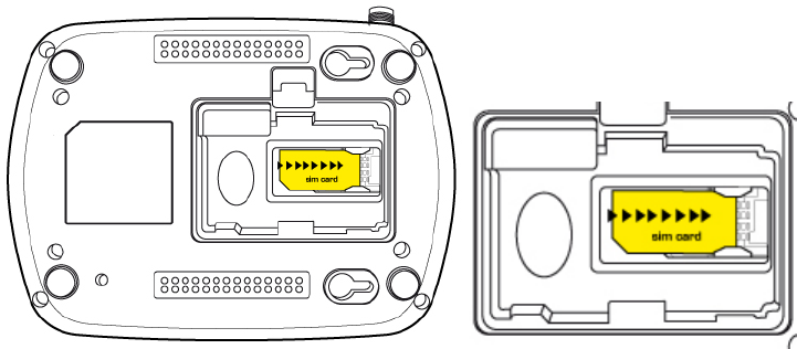
1.3. SIM card installation
1. Disconnect the power supply.
2. Open battery cover on the bottom side of the TG130.
3. Disconnect the DC power cable to TG130
4. Take out the battery pack in the right position between the hold bars
5. Insert the SIM card into the socket as shown in the picture.
* Note: Make sure the SIM card is aligned properly with the directional arrow on the holder.
6. Connect the DC power cable to TG130.
7. Insert the battery pack in the right position between the hold bars.
8. Close the battery cover.
9. Connect the power supply to TG130.
- 9 -
© QuestLabs Limited
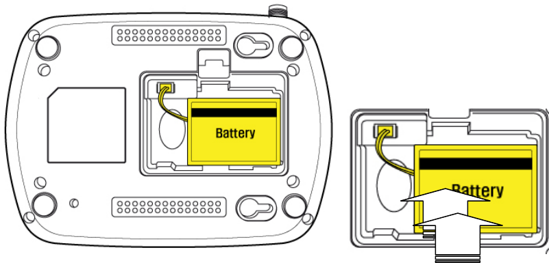
1.4. Battery installation
1. Disconnect the power supply.
2. Open battery cover on the bottom side of TG130.
3. Connect the DC power cable to TG130.
4. Close the battery cover.
5. Connect the power supply to TG130.
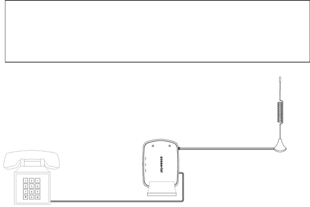
1.5. Installation of the antenna and location of the equipment for voice service
Before you select a localization to place TG130(F), you should read the section for their Security in the first
part of this manual. You can place it in a plane area just as the floor, the walls or the desk or table.
1. it connects the antenna at the TG130(F) (previously it should couple the antenna in their support, make
sure of making the one it couples in a complete way, verify that the antenna mo is slack) and locate her it
more far possible of the terminal. If the antenna is located near the TG130(F) noise she/he will take place
during the communication, avoid it!
* Notices: make sure of pressing the antenna completely to their connector in the terminal.
2. Using the marked port as “Phone “connects the TG130(F) to the central PBX, or to the system of tariff of
the booth or a similar telephone. If their Terminal is model TG130F and you will use similar fax, connect the
fax machine to the port “Fax ".
3. Connect the adapter to the Terminal. Use the connector "DC Input."
4. Connect the adapter DC in an appropriate energy plug.
5. Turn on the terminal. Use the switch “On/Off ".
6. Checks the power of the signal GSM, verify the state of the led “Signal “(check the section 2.1). To improve
the signal reception, move the antenna and verify the state of the led “Signal ".
Avoids leaving the antenna in a location in which the led illuminates red or be shut down
7. The terminal is ready to be used.
- 10 -
© QuestLabs Limited
Attention: If the SIM Card (Chip) that will be used in the terminal has the number disabled PIN (it consults
to their operator), it won't be necessary to make some additional configuration in the TG130(F); this will be
ready for their use.
In case, on the contrary, the SIM Card has the active PIN that same number PIN it will be recorded in the
terminal. To make it, connect a telephone similar to the port “Phone” and dial: #* 110 * 2 * number PIN #
With the previous procedure it will be engraving in the terminal the number PIN. It is this way when the
terminal is out and then lit, it won't be necessary to carry out this procedure again. Although the Terminal
remains out a lot of time, without current and without battery, the PIN that was recorded will always remember.
IF THE PIN OF THE SIM CARD (CHIP) IT IS ACTIVATED AND SHE/HE IS NOT CARRIED OUT THE
PREVIOUS PROCEDURE CORRECTLY, THE SIM CARD WILL BE ABLE TO BE BLOCKED AND YOU
WILL HAVE TO ENTER THE NUMBER PUK TO UNBLOCK IT (TO CONSULT SECTION 4.9).
Avoid noise or interference during the communication: the antenna should be at least separated from the equipment a
meter. Avoid proximity of the team and of their antenna to electric motors, fluorescent lamps, radios, televisions,
computer monitors, speakers and in general electric equipment. Before connecting the terminal to central PBX, verify
connecting a direct telephone and making calls of test that there are not noise or interference during the call; if there is
verify the location of the equipment and their antenna.
- 11 -
© QuestLabs Limited
1.6. Desktop installation
Before you select a location to place TG130, you must read “For your safety” section in the first part of this
manual.
You can place it on the flat surface area such as above ground, on the walls, or table.
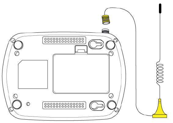
1. Connect the antenna to TG130 and locate it as far as it can reach
* Note : finger-tighten the antenna.
2. Connect a wire telephone to TG130 using phone cord
3. Connect the barrel connector of the power supply to DC Adaptor
4. Plug the DC Adaptor into the power supply.
5. Plug the DC Adaptor into an appropriate power outlet.
6. Check signal strength moving the antenna until you find the best signal possible.
(See 2.1 LED Status Indicator section)
7. If you use Data Service or PC FAX Service, connect your data cable to the Data port located at the side
of TG130.
8. If you use G3 FAX machine, connect your line cord of G3 FAX to the RJ-11port located at the side of
TG130F.
- 12 -
© QuestLabs Limited
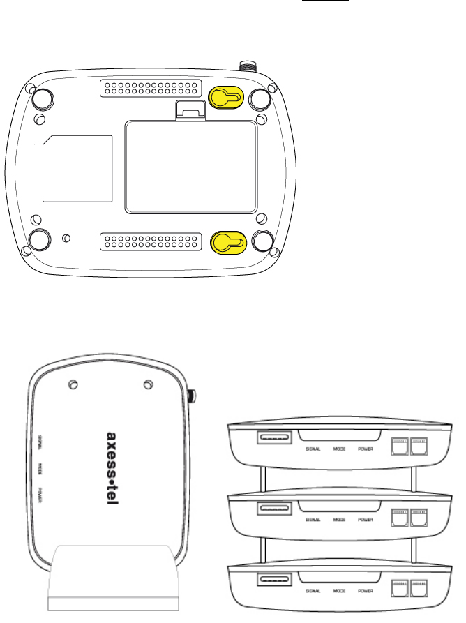
1.7. Wall mounting
1. Mark two mounting hole locations to match the screw hole in the back of TG130.
2. Drill two holes at the marked locations.
3. Tighten the screws until the head is about 3~5mm from the wall.
4. Hang TG130 on the screw using the two holes in the back.
5. Push TG130 down until the unit is firmly locked into place.
1.8. how to use the supports

- 13 -
© QuestLabs Limited
2. Getting To Know TG130
2.1. LED Status Indicator
When your TG130 is powered on, the LED Status Indicators show operation of the indicators and the modes.
When your TG130 is turned on, the LED Status Indicators show operation of power status, signal strength and
current mode.
* Note : If you are getting no service or limited service, contact your service provider.
1. LED STATUS INDICATOR
1) POWER
LED COLOR ACTIVITY DESCRIPTION
GREEN Continuous Normal
AMBER Continuous Charging
RED Continuous Low
RED Flashing Very Low
2) SIGNAL
LED COLOR ACTIVITY DESCRIPTION
GREEN Continuous High
AMBER Continuous Middle
RED Continuous Low
RED Flashing Limited Service
OFF Continuous No Service
3) MODE
LED COLOR ACTIVITY DESCRIPTION
GREEN Continuous Fax/Data Call
GREEN Flashing Incoming Fax/Data Call
RED Continuous Off-Hook or Voice Call
RED Flashing Incoming Voice Call

- 14 -
© QuestLabs Limited
4) EXCEPTION STATUS
LED ACTIVITY DESCRIPTION
ALL LED Flashing(Red) then
Mode LED : GREEN Insert SIM
ALL LED Flashing(Red) then
Signal LED : GREEN
Equipment Locked, Enter Lock Code
(See 4.8 Equipment Lock section)
ALL LED Flashing(Red) then
Signal LED : AMBER
PIN Locked, Enter PIN
(See 4.9 PIN Lock section)
ALL LED Flashing(Red) then
Signal LED : RED
PIN Blocked, Enter PUK *
(See 4.9 PIN Lock section)
ALL LED Flashing(Red) then
Mode LED : AMBER MEP Locked *
ALL LED Flashing(Red) then
Mode LED : RED AUTO PIN Locked **
ALL LED Flashing(Red) then
Mode LED : GREEN Cell Locked *
* Contact your service provider to verify that service has been activated.
** If your service provider use AUTO PIN feature, you must use the SIM card provided from your service
provider. If a proper SIM card is installed and ‘AUTO PIN Locked’ state continues, contact your service
provider.
3. Basic operations
3.1. Making calls
1. Check to see that your TG130 is turned on.
2. Pick up the handset of the phone.
3. If you listen for dial tone, dial the desired telephone number. The call will be automatically made by TG130.
If you hear fast beep tone, check SIM card or signal strength.
* Note : If you can’t hear dial tone produced, check to make sure that all the parts are properly connected,
hang up the phone, and try again.
If you press ‘Flash key’, or press the switch-hook and release after dialing a number,
Call will be made immediately.
3.2. Receiving calls
1. When the phone rings, pick up the telephone handset, begin to talk.
2. To disconnect after finished, replace the handset on the phone.

- 15 -
© QuestLabs Limited
* Note : When there is an incoming call when you are already holding the receiver, press ‘Flash key’ to answer
the call.
4. Basic Settings
4.1. Receiver Volume
You can control the volume level in the range of 1 to 7 using the keypad on the telephone.
Set Receiver Volume # * 100 * <level> # level : 1 - 7
Default volume is “5”.
4.2. Dial Delay Time
You can set dial delay time that your TG130 waits after the phone number is dialed before automatically
sending the number.
Set Dial Delay Time # * 101 * <delay> # delay : 3-20 seconds
Default delay time is 3 seconds.
4.3. Speed Dial Entry
You can store up to 10 frequently used phone numbers in the ‘SIM card’ memory and you can make a call by
pressing record number.
Add/Modify # * 102 * <N> * <NNNN> # N : Record number(0-9)
NNNN : Phone number
Delete # * 103 * <N> # N : Record number (0-9)
Call using speed dial # * <N> # N : Record number (0-9)
4.4. Time and Date
You can set time and date to be displayed on a connected caller ID device.
Set Time # * 104 * <HH><MM> # HH : Hours(24h)
MM : Minutes
Set Date # * 105 * <MM><DD><YYYY> #
MM : Month
DD : Day
YYYY : Year
For 2:30 PM, press # * 104 * 1430 #
For 31 DEC 2007, press # * 105 * 12312007 #
* Note : This function is dependent on the phone connected to TG130..
4.5. CID Format
You can set CID format that is available on wire phone with CID function.

- 16 -
© QuestLabs Limited
SDMF format # * 106 * 1 # Default
MDMF format # * 106 * 2 #
* Note : SDMF stands for Single Data Message Format and MDMF stands for Multiple Data Message Format.
4.6. Band Selection
Your phone supports quad frequency band.( GSM900, DCS1800, GSM850, and PCS1900)
This feature depends on your service provider’s setting.
GSM900/DCS1800 # * 108 * 1 #
GSM850/PCS1900 # * 108 * 2 #
GSM900, DCS1800,
GSM850, PCS1900 # * 108 * 3 #
4.7. Equipment Lock
The lock code prevents TG130 from being used by unauthorized person without your permission. The default
lock code is 0000.
When equipment lock is activated, you must enter lock code using ‘Enter Lock Code’ string every time the
TG130 is turned on. (See 2.1 LED Status Indicator section)
Activate # * 109 * 1 * <password> #
Deactivate # * 109 * 0 * <password> # Default
Enter Lock Code # * 109 * 2 * <password> # password : 4 digits
Change Lock Code # * 109 * 3 * <old password> *
<new password> #
4.8. Polarity Reverse
This feature is provided for metering or PBX.
Activate # * 111 * 1 #
Deactivate # * 111 * 0 #
4.9. Loop Current Disconnect
This feature is provided for metering or PBX.
Activate # * 112 * 1 #
Deactivate # * 112 * 0 #
4.10. DTMF tone generation
This feature is provided for specific PBX.
By wire phone # * 113 * 0 # default
By TG130 # * 113 * 1 #

- 17 -
© QuestLabs Limited
For recharging prepaid SIM card #* 113 * 2 #
* Note : In case of setting “FOR RECHARGING PREPAID SIM CARD”, default value will be automatically set
after the call was disconnected.
4.11. Factory Reset
This function is used to change the main settings of the terminal back to the default settings, which were
programmed into the terminal at the factory.
Factory Reset # * 119 * <password> #
4.12. PIN Lock
The SIM card has a PIN to prevent TG130 from being used by unauthorized person without your permission.
The PIN can be between 4 and 8 digits in length and any combination of digits 0 to 9.
When PIN lock is activated, you must enter the PIN using ‘Enter PIN’ string.
You have several chances to enter the PIN. If incorrect PIN is entered maximum times consecutively, the SIM
card will be blocked. To unblock the SIM card, you must enter the PUK using ‘Enter PUK’ string.
(See 2.1 LED Status Indicator section)
A correctly entered PIN is stored in TG130’s memory. The PIN will be entered automatically upon the next
power up.
Activate # * 110 * 1 * PIN #
Deactivate # * 110 * 0 * PIN #
Enter PIN # * 110 * 2 * PIN #
Enter PUK (Unblock SIM Card PIN) # * 110 * 4 * PUK * New PIN #
Change SIM Card PIN ** 04 * old PIN * new PIN * new PIN #
4.13. Automatic PIN Entering
You do not need to enter the PIN upon power up if it is stored in TG130 – the PIN is entered automatically.
This function is convenient in case of power failure; TG130 would be operable in a short time after power
recovery without any intervention by the operating staff.
Note: When the Automatic PIN Entering is attempted with the incorrect PIN stored in TG130. The TG130
would make alert signals with LED(See 2.1 “Exception Status” section). There is the manual PIN-entering way
after such unsuccessful automatic entering(See 4.12).

- 18 -
© QuestLabs Limited
5. Supplementary Service Features
5.1. Call Forwarding
An incoming call can be delivered to another telephone number programmed.
Please contact your service provider for availability.
1) All Calls
You can send all incoming calls to a different number using this feature.
Activate & register number * * 21 * <Number> # Flash
Deactivate & deregister number # # 21 # Flash
Activate * 21 # Flash
Deactivate # 21 # Flash
2) No Answer
When your phone is not answered after certain amount of time, you can send all incoming calls to a different
number.
Activate & register number ** 61 * <Number> * 10 * <Delay> # Flash Delay : 5 – 30 Seconds
Deactivate & deregister number ## 61 # Flash
Activate * 61 * <Number> # Flash
Deactivate # 61 #
3) Unreachable
When your account is not reachable, you can send all incoming calls to a different number.
Activate ** 62 * <Number> # Flash
Deactivate ## 62 # Flash
4) Busy
When your account is Busy, You can send all incoming calls to a different number.
Activate * * 67 * <Number> # Flash
Deactivate # # 67 # Flash
5) All Types
To deactivate all type of ‘Call Forwarding’ feature,
Deactivate ## 002 # Flash

- 19 -
© QuestLabs Limited
5.2. Call Barring
Call Barring is a feature, which the specified numbers cannot be called.
1) Bar all outgoing calls
Does not allow all outgoing calls, but still wish to receive incoming calls at any time.
Activate * 33 * PIN # Flash
Deactivate # 33 * PIN # Flash
2) Bar all outgoing international calls
Does not allow all outgoing international calls to the subscribers of networks outside country you are in. But
still wish to receive incoming calls at any time.
Activate * 331 * PIN # Flash
Deactivate # 331 * PIN # Flash
3) Bar all outgoing international calls when roaming (except to home country)
Does not allow all outgoing calls to countries other than the one where your home network is located.
Activate * 332 * PIN # Flash
Deactivate # 332 * PIN # Flash
4) Bar all outgoing calls
Does not allow all outgoing calls, but still wish to receive incoming calls at any time.
Activate * 333 * PIN # Flash
Deactivate # 333 * PIN # Flash
5) Bar all Incoming Calls
Does not allow all incoming calls but still wish to make outgoing calls at any time.
Activate * 35 * PIN # Flash
Deactivate # 35 * PIN # Flash
6) Bar all incoming calls when international roaming
Does not allow all incoming calls when you are roaming outside the country where your home network is
located. But still wish to make outgoing calls at any time.
Activate * 351 * PIN # Flash
Deactivate # 351 * PIN # Flash

- 20 -
© QuestLabs Limited
7) Bar all calls
Does not allow all incoming or outgoing calls.
Activate * 350 * PIN # Flash
Deactivate # 350 * PIN # Flash
8) Bar all incoming calls
Does not allow incoming calls but still wish to make outgoing calls at any time.
Activate * 353 * PIN # Flash
Deactivate # 353 * PIN # Flash
9) Deactivate all call barring
Deactivate # 330 * PIN # Flash
5.3. Call Waiting
Call Waiting is a feature, which enables you to be alerted to another incoming call while you are on the call of
your telephone.
These features are network-dependent. Contact your service provider to activate or deactivate Call Waiting.
Activate * 43 # Flash
Deactivate # 43 # Flash
The following table describes multiparty call features. These features are handled within an active call.
Contact your service provider for availability.
FEATURE STRING DESCRIPTION
Reject call waiting or end call
on hold 0 Flash Release all held calls or set User Determined User
Busy for a waiting call
End active call and switch to
held or waiting call 1 Flash Release all active calls and accept the held/waiting
call
End a specific call 1<n> Flash n = call number
release a specific active call
Hold active call and retrieve
held or waiting call 2 Flash Place all active calls on hold and accept the
held/waiting call
Hold all active calls and
except one 2<n> Flash n = call number
Place all active calls on hold except call <n>
Add held call into active call 3 Flash Add a held call to the conversation
Hold active call and place
outgoing call <Number> Flash Place all active calls on hold and make a call to a
specified number

- 21 -
© QuestLabs Limited
5.4. Caller ID
1) Incoming (CLIP: Calling Line Identification Presentation)
You can activate the identification information presentation - name and number- of person calling you.
Activate * 30 # Flash
Deactivate # 30 # Flash
2) Outgoing (CLIR : Calling Line Identification Restriction)
You can prevent your identification information from be presentation to person you call.
Activate * 31 # Flash
Deactivate # 31 # Flash
3) Outgoing per-call block
To hide your information for the next call only.
Activate * 31 # <Number> Flash
Deactivate # 31 # <Number> Flash
6. Data Service Features
You can send and receive digital fax and access internet if TG130 is connected to the personal computer.
Before you start, Please refer to Appendix A(HOW TO SET UP DATA CONNECTION FOR CSD FAX/DATA
AND GPRS DATA)
7. Fax Service Feature
7.1. Analog Fax
1) TG130F supports
- ECM (Error Correction Mode)
- Max 14.4kbps (Local – directly plugged)
- Max 9.6kbps (Network)
- Multiple-page
You can answer faxes through analog fax by setting up the fax-port of TG130F to RJ-11.
And before sending faxes, you need to setup TG130F to fax-mode as below.

- 22 -
© QuestLabs Limited
FEATURE MODE STRING DESCRIPTION
Bypass Mode
Voice #* 300 * 0 # Outgoing Call is whether Voice or
Fax.
Fax #* 300 * 1 #
Fax Once #* 300 * 2 #
Fax Port Selection Serial port(Digital) #* 301 * 0 # Incoming fax call is where to be
routed.
RJ-11(Analog) #* 301 * 1 #
Fax National Setup #* 302 * 2 # Fax machine should be connected
Note: Every fax machine has settings to communicate in specific country. If you have a problem of
transmission between TG130F and local fax machine, you can change the national configuration of TG130F
by pressing dial #*302*2#. The setting is originally configured by SIM, but after performing this national-setup
TG130F will automatically find out the correct setup.
Note: After failure of sending faxes due to network problem or not working fax line, TG130F tries to transmit
twice more to designated fax machine. If the transmission was not successful in spite of 3-tries, you will
receive error report.
TG130F also tries to transmit to local fax twice more if failed to transmit faxes successfully got from remote
fax machine beyond network.
7.2. Digital Fax
1) TG130 supports
- Max 9.6kbps
TG130 can be used with any fax-software application on PC. Before using fax capability, you should verify
TG130 was plugged in PC. After then choose the right COM-Port for TG130 on your application.
When you answer faxes, you should set up TG130 to digital-mode as below.
Serial port(Digital) #* 301 * 0 #
RJ-11(Analog) #* 301 * 1 #
NOTE: Every fax specification except max-speed will be taken care of by your fax-software application

- 23 -
© QuestLabs Limited
8. General Information
8.1. Specifications
MAIN UNIT
ITEM TG130/TG130F
Frequency range GSM850, GSM900, DCS1800, PCS1900
Protocol GSM , GPRS Class B
Multi connection 5 REN
Connection port RJ11 port(For Phone/Fax), Serial port(Data/Fax)
Size(mm) 160*158*26
Weight about 268g with a standard battery
Working condition
Environment temperature: -10℃ ~ 50℃
Relative humidity : 10~95%
Air pressure : 86~106kpa
AC/DC ADAPTER
Input voltage AC100-240V
Input Frequency 50/60Hz
output voltage 5V 1A
INTERNAL BACK-UP BATTERY
Capacity Li-ion battery 3.7V, 1000mAh
8.2. Additional Safety Information
For further assistance, contact your Authorized Distributor for service and assistance. Please keep your Model
number and Serial number ready for quicker service.
EVERYDAY USE OF YOUR TG130
Do not touch the antenna unnecessarily when your TG130 is in use, as this will affect call quality and may cause
TG130 to operate at a higher power level than otherwise needed.
As with any other radio transmitting equipment, you are advised that for the satisfactory operation of your TG130
and for your own safety, you should use your TG130 only in the normal operating position.
- 24 -
© QuestLabs Limited
NON-IONIZING RADIATION (EXPOSURE TO RADIO FREQUENCY SIGNALS)
Your TG130 is a low power radio transmitter and receiver. When it is on, it receives and also sends the radio
frequency(RF) signals. Most modern electronic equipment is shielded from RF signals. However, certain
electronic equipment may not be shielded against the RF signals from your TG130. RF signals may affect
improperly installed or inadequately shielded electronic systems in motor vehicles. Consult your vehicle
manufacturer and the manufacturer of any equipment that has been added to the vehicle.
PACEMAKERS
The Health industry Manufacturers Association recommends that a minimum separation of six inches be
maintained between TG130 and a pacemaker to avoid potential interference with the pacemaker. Users with
pacemakers:
Always keep your TG130 at least 20 cm (6inches) from your pacemakers when the TG130 is switched on.
Switch off your TG130 immediately if you suspect that interference is being caused.
OTHER MEDICAL DEVICES
If you use any other medical devices, please consult a physician or the manufacturer of the medical devices to
determine if they are adequately shielded from external RF energy. Your physician may be able to assist you in
obtaining this information. Always check the regulations of the healthcare facilities, which generally request that
TG130 is switched off .
OPERATING ENVIRONMENT
Remember to follow any special regulations in force in any area, and always turn off your TG130 wherever it is
forbidden to use it, or when it may cause interference or danger.
EXPLOSIVE ATMOSPHERES AND MATERIALS
Turn your TG130 off and do not remove the battery when in any area with a potential explosive atmosphere and
obey all signs and instructions. You must observe restrictions on the use of radio equipment in fuel depots; below
deck on boats; fuel or chemical transfer or storage facilities; areas where the air contains chemicals or particles,
such as grain, dust, or metal powders; areas with signs about explosive atmospheres or where blasting
operations are in progress; any other areas where you would normally be advised to turn off your vehicle engines.
BATTERY CHARGING
Do not charge TG130 without the battery in place.
Please use only approved batteries and chargers.
- 25 -
© QuestLabs Limited
8.3. Guarantee
Limited guarantee for the products of personal communication, accessories and software.
What does it cover this guarantee? According to the contained exclusions Axesstel guarantees its products next,
(" products "), this free of defects in materials and of manipulation under the consumer's normal use for the
period(s) sketched next. This limited guarantee is the consumer's exclusive remedy, and it applies like it continues
to new products that are accompanied by this written guarantee:
COVERED PRODUCTS
1. Wireless fixed telephone.
2. The accessories included with the wireless fixed telephone.
EXCLUSIONS
Batteries. Only batteries whose loaded capacity totally falls below 80% of its capacity average, and
batteries that its escape is covered by this limited guarantee.
Abuse and wrong use. Defects or damages that are of: (to) inappropriate operation, storage, wrong
use or abuse, accident or negligence, like physical damage (cracks, scratches, etc.) TO the surface of
the product that you/they are the result of the wrong use; (b) I contact with liquid, it dilutes, rain,
extreme humidity or heavy perspiration, corrosion, dirt or similar, extreme heat, or eaten; (c) I use of the
product for commercial purposes or to subject the product to use or abnormal conditions; or (d) other
acts that are not blame of Axesstel, are excluded of the cover
Use of products and non original accessories: defects or damage that are the result of the use of
products, accessories, software or other outlying teams not marked or certificates as original, are
excluded of the guarantee
- 26 -
© QuestLabs Limited
Altered products: Products or accessories with (to) series numbers or date labels that they have
been removed, altered or erased; (b) stamps that show evidence of manipulation; (c) series numbers
that don't agree; or (d) housing or non compatible pieces or of mark different to the original, they are
excluded of the guarantee
Communication services: Defects, damages, or flaw of products, due to any communication service
or sign to which you have subscribed or used with the products they are excluded of the covering.
WHO ARE COVERED?
This guarantee only extends to the first consumer/buyer, and it is not transferable.
WHAT WIL AXESSTEL Make?
Axesstel, to its will, without position for you, will repair, it will replace or it will reinstate the price of the
purchase of any product that is not according to this guarantee. We can use products, accessories or
reconditioned equivalent parts, restored of second hand functionally or new. Any fact,
software or applications that have been added to their product, accessory or software, included but
not limited to the personal contacts, games and bell tones, it will be reinstalled. To please avoid to lose
such data, software and applications; she/he believes a back of those data before requesting the
service.
HOW TO OBTAIN SERVICE OF GUARANTEE OR OTHER INFORMATION
For information in how to obtain service, contact the place where the product was bought or a center
of service Axesstel in its country.
So that this guarantee has effect, take its unit, together with this policy, to the purchase place or a
center of authorized service Axesstel.
You will receive instructions of as sending the products, to his expense, to an authorized repair center
of Axesstel. To obtain service, you should include: (to) a copy of their receipt, sale invoice or another
test comparable of purchase, (b) a written description of the problem; (c) their supplier's of service
name, if it applies; (d) the name and lease of the establishment of the installation (if it applies) and, but
important; (and) their address and telephone number.
HOW OTHER LIMITATIONS EXIST?
Any implicit guarantee includes without limitation the implicit guarantees of commercial and aptitude
for a particular purpose, it will be limited to the duration of this limited guarantee, on the other hand the
repair, substitution, or provided refund lower this limited guarantee it is the consumer's exclusive
remedy, and it is provided instead of all the other guarantees, expressly or implicitly. In any event

- 27 -
© QuestLabs Limited
Axesstel will be responsible, either in contractual or civil environments (even negligence) for damage
and damages for but of the price of purchase of the product, or for any indirect, incidental damage,
special of any type. Or lost of earnings or dismissed lucre, lost of business, lost of information or data or
another lost one financial that arise of the capacity or inability of using the products, the magnitude of
these damages will be able to be denied by the law
Some states and jurisdictions don't allow the limitation or the exclusion of incidental or rising
damages, or limitation in the duration of an implicit guarantee, so the previous limitations or exclusions
can not be applied you. This guarantee gives him right legal specific, and you can also be entitled other
that vary from state to state or of a jurisdiction to another.
Axesstel corp. declares that this unit is according with the excellent provisions of the directive one of
low voltage 73/23/eec and the directive emc 89 / 336 / eec.
The certification alone fcc applies for the pattern of frequency 850-1900 MHz.
The version frequently 900-1800 MHz this marked one as agreement ce-mark with the directive
related European.
Warning of FCC to the users
This device fulfills the part 15 of the rules of the fcc. The operation is subject to the following two
conditions:
: (1) this device can not cause harmful interference, and
: (2)this device should accept any received interference, even interference that can cause not wanted
operation.
If their device or accessory has a connector usb, or it is on the other hand it is considered then as
outlying device of computer that can be connected to a computer for purposes of transferring data, a
device class it is considered b it applies the following declarations:
- 28 -
© QuestLabs Limited
This team has been proven and she/he has been that it fulfills the limits for a device class digital b,
rising to the part 15 of the rules of the FCC. These limits are designed to provide reasonable
protection against the harmful interference in a residential installation.
This team generates, it uses and it can radiate radiofrequency energy and, if it doesn't install and it
uses of agreement with the instructions, it can cause harmful interference to the radio
communications.
However there is not any guarantee that the interference doesn't happen in a particular installation. If
this team causes harmful interference to the radio reception or television which can be determined
turning off and lighting the team, the user can try to correct the interference through an or more than
the following measures:
To reorient or re to locate the antenna receptor
To increase the separation between the equipment and the receiver.
To connect the team to an electric outlet in a circuit different to which the receiver is connected.
To consult with their salesperson authorized by a technician with experience in radio that helps him.
Exhibition guide to the RF
During transmission operations in order of completing the guides of you limit them maxima of
exhibition to the RF a minimum distance of 20 cm it should be maintained between the antenna and
the user of the telephone.
Information of CE
Hereby, Axesstel Inc declares that this TG130/TG130F is in compliance with the essential
requirements and other relevant provisions of directive 1999/5/EC
Directive of the UE 2002/96/EC in Waste Electrical and Electronic Equipment (WEEE):
Axesstel Corporation this focused in fulfilling the program of the European Union as for the handling
of electronic waste. We are committed in completing to honesty the environmental standards in the
production of all our products in order of completing these directive ones.

- 29 -
© QuestLabs Limited
8.4. Troubleshooting
ITEM REMEDY
No power Check the power adaptor connection
Check for the appropriate service indication on the LED.
Telephone service is not
Working
Make sure TG130 powered on properly.
Check any equipment connected to the TG130 is correctly connected.
Make sure your service is established with a service provider.
Call can not be received.
Check the appropriate power indication on the LED
Check signal strength.
Make sure handset is placed on the cradle
Call can not be made. Make sure your service is established with a service provider.
Check any equipment connected to the TG130 is correctly connected.
Adequate signal is not
present Try different locations for the better signal reception.
Analog fax calls isn’t sent or
received
Check the appropriate power indication on the LED
Check the cable is correctly connected to the TG130F
GPRS service isn’t
Connected.
Check the cable connection
Contact the GPRS service provider whether you have service on the
account.
FCC WARNING:
This equipment may generate or use radio frequency energy. Changes or modifications to this equipment may
cause harmful interference unless the modifications are expressly approved in the instruction manual. The user
could lose the authority to operate this equipment if an unauthorized change or modification is made.
- 30 -
© QuestLabs Limited
APPENDIX A:
HOW TO SET UP DATA CONNECTION FOR CIRCUIT SWITCHED DIGITAL FAX/DATA AND GPRS DATA
1. INTRODUCTION
FOR THE DATA CONNECTION, BELOW REQUIREMENTS ARE NEEDED.
- SIM CARD FROM YOUR NETWORK SERVICE PROVIDER FEATURING CSD OR GPRS .
- PC OR LAPTOP WITH USB PORT
- WINDOWS 2K OR LATER VERSION
- USB DATA CABLE INCLUDED IN BOX
NOTE THIS MANUAL IS FOR WINDOWS XP. SETTING IN OTHER WINDOWS VERSIONS IS SIMILAR.
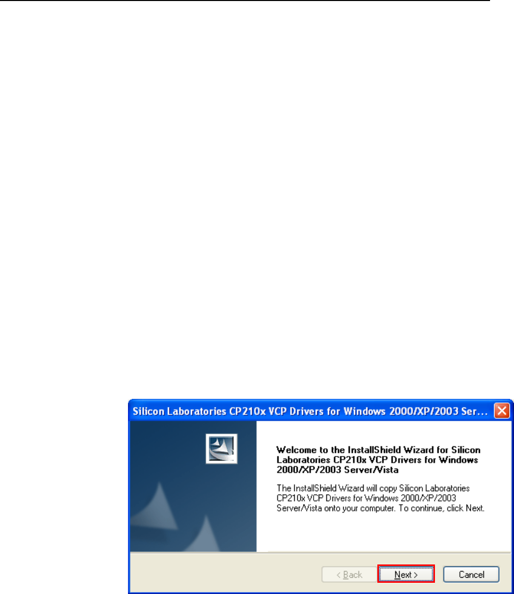
2. INSTALL THE DRIVER FILES
1. EXTRACT THE DRIVER FILE “CP210X_VCP_WIN2K_XP_S2K3.ZIP”
NOTE 1 PLEASE ASK THE DRIVER FILE AT THE PLACE WHERE YOU BOUGHT PHONE OR TERMINAL
NOTE 2 DOWNLOAD ALSO AVAILABLE ON THE VCP(VIRTUAL COM PORT) DRIVER MANUFACTURER’S
HOMEPAGE:HTTP://WWW.SILABS.COM/TGWWEBAPP/PUBLIC/WEB_CONTENT/PRODUCTS/MICROCON
TROLLERS/USB/EN/MCU_VCP.HTM
VERSION 4.40 SHOULD ONLY BE USED, IF NOT AVAILABLE. EMAIL TO: SUPPORT@QUESTLABS.CO.KR
2. THEN, MANY FILES ARE EXTRACTED IN THE DIRECTORY WHERE YOU UNZIPPED.
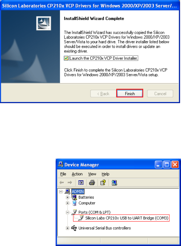
3. EXECUTE THE FILE “CP210XVCPINSTALLER.EXE” FOR INSTALLING DRIVER.
- 31 -
© QuestLabs Limited
NOTE AFTER INSTALLING DRIVER FILE, YOU COULD NEED TO REBOOT THE PC.
3. INSTALL NEW MODEM
CONNECT THE PHONE TO PC USING USB DATA CABLE, CABLE DRIVER IS INSTALLED
AUTOMATICALLY.
AFTER INSTALLING YOU CAN SEE NEW PORTS (COM & LPT) IN A DEVICE MANAGER WINDOW.
NOTE IN THE COM3, COM PORT NUMBER COULD BE DIFFERENT ON THE PC ENVIRONMENT.
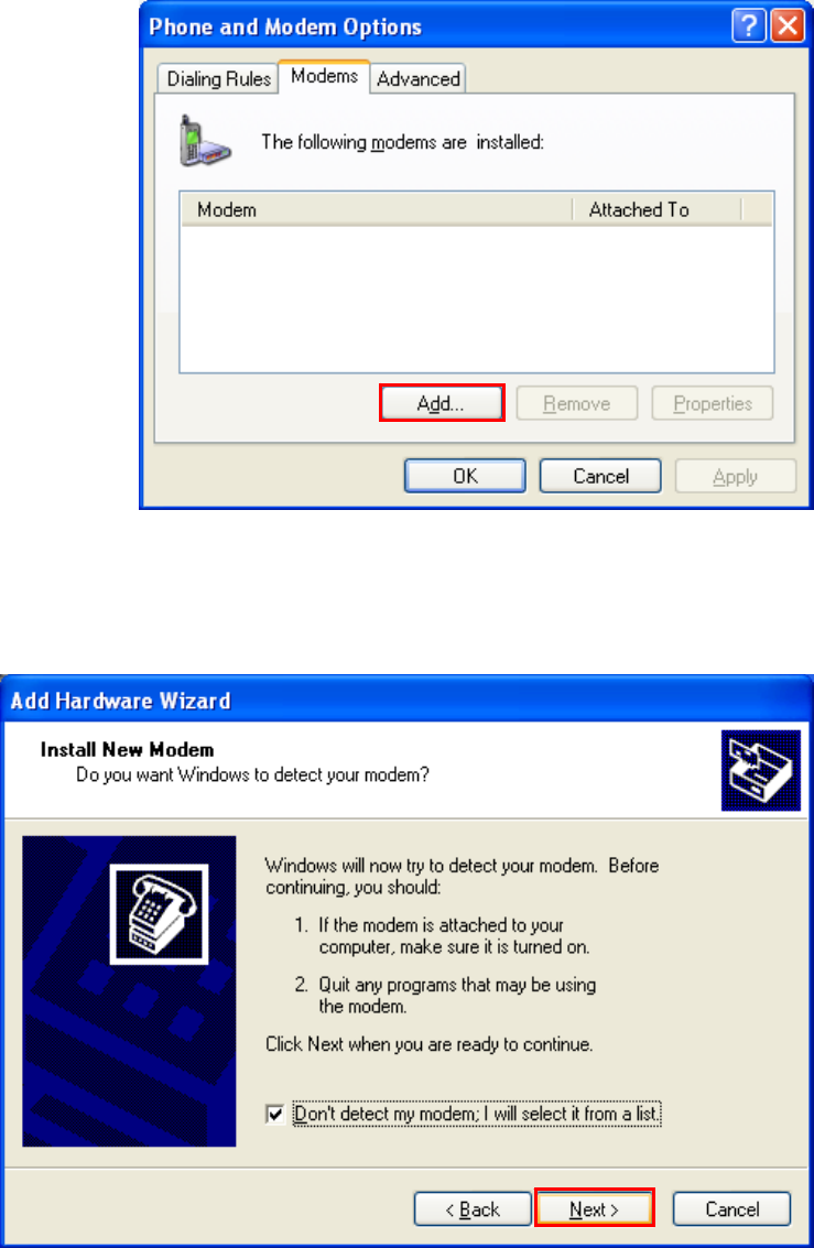
GO TO THE “NETWORK CONNECTIONS” MENU.
START BUTTON > CONTROL PANEL > PHONE AND MODEM OPTIONS
AND SELECT THE ADD BUTTON FROM MODEMS FROM TAP MENU.
- 32 -
© QuestLabs Limited
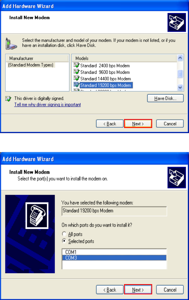
SET AS SHOWN BELOW. AND PRESS THE NEXT BUTTON.
- 33 -
© QuestLabs Limited
SELECT “[STANDARD MODEM TYPES]” AND “STANDARD 19200 BPS MODEM”. AND PRESS THE NEXT
BUTTON.
SELECT A APPROPRIATE PORT THAT YOU HAVE SELECTED. THIS MAY TAKE SEVERAL MINUTES.
NOTE IN THE COM3, COM PORT NUMBER COULD BE DIFFERENT ON THE PC ENVIRONMENT.
- 34 -
© QuestLabs Limited
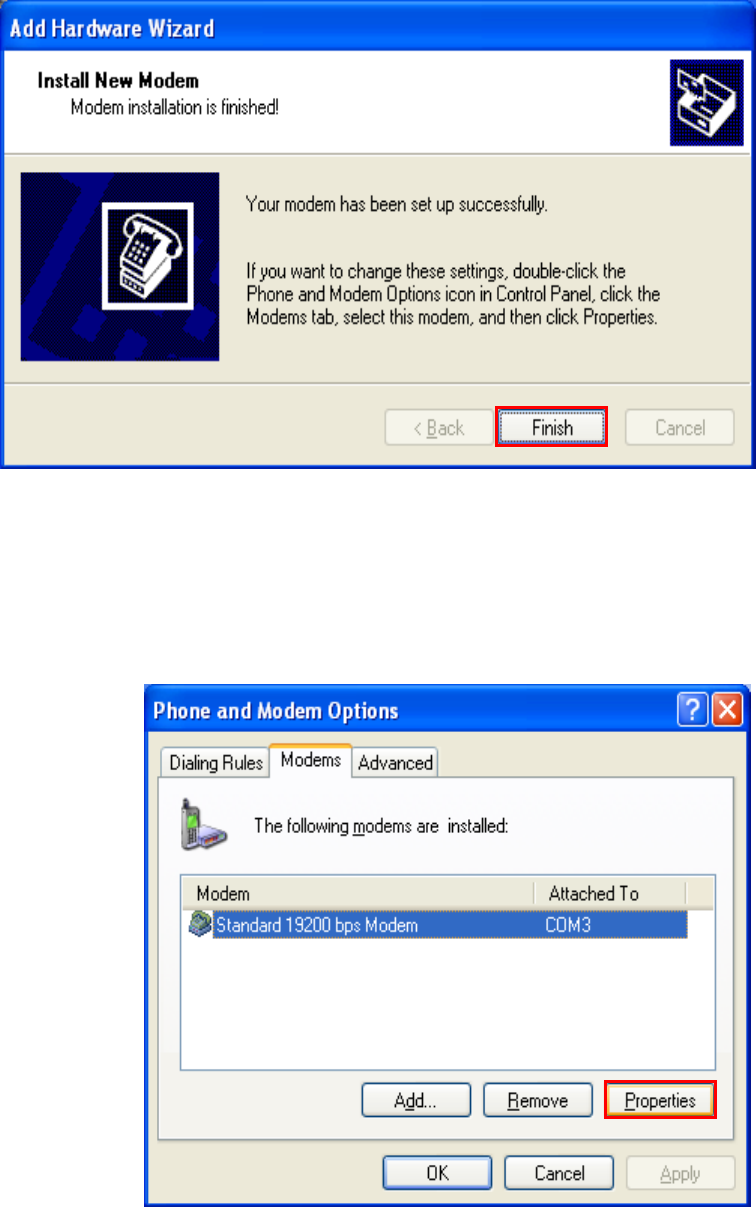
IF YOU SEE BELOW WINDOW, MODEM IS INSTALLED SUCCESSFULLY.
NEW MODEM IS LISTED IN BELOW WINDOW.
SELECT THE NEW MODEM, AND PRESS THE PROPERTIES BUTTON FOR SETTING.
- 35 -
© QuestLabs Limited
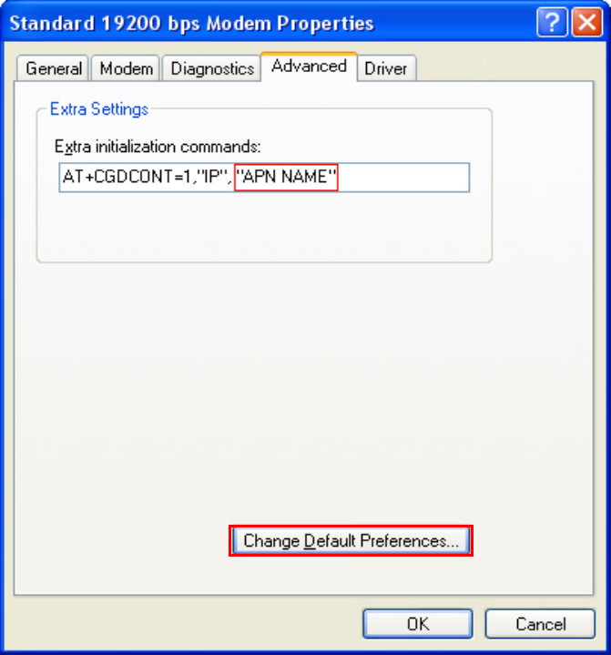
SELECT “ADVANCED” TAB MENU.
THE APN NAME MAY BE DIFFERENT ON EVERY SERVICE PROVIDERS AND PERHAPS SOME SERVICE
PROVIDERS DO NOT REQUIRE APN NAME. SO YOU SHOULD CHECK FIRST WITH YOUR SERVICE
PROVIDER OF USING APN NAME. IF YOUR SERVICE PROVIDER REQUIRES THEIR OWN APN NAME TO
BE ENTERED, YOU MUST HAVE TO ENTER BELOW INITIALIZATION COMMANDS EXACTLY WITH
CHANGING APN NAME(RED BOX) AS REAL APN NAME PROVIDED BY SERVICE PROVIDER. IF APN NAME
DOES NOT NEED, LEAVE THE WHOLE INPUT BOX IN BLANK.
- 36 -
© QuestLabs Limited
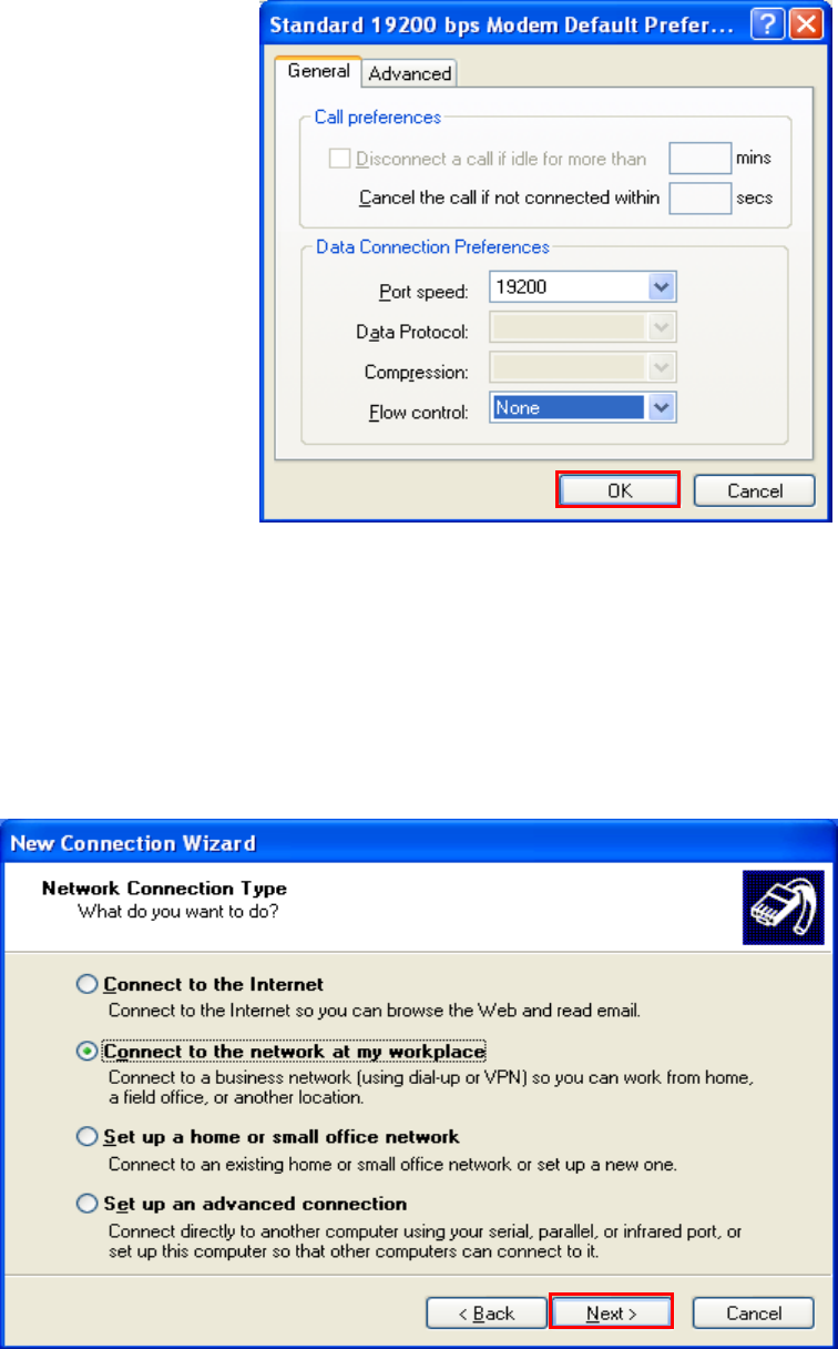
SELECT “CHANGE DEFAULT PREFERENCES...”. AND SET AS BELOW WINDOW. AND PRESS THE OK
BUTTON.
4. CREATE NEW NETWORK CONNECTION
GO TO THE “CREATE A NEW CONNECTION” MENU.
START BUTTON > CONTROL PANEL > NETWORK CONNECTIONS > CREATE A NEW CONNECTION
SELECT “CONNECT TO THE NETWORK AT MY WORKPLACE”. AND PRESS THE NEXT BUTTON.
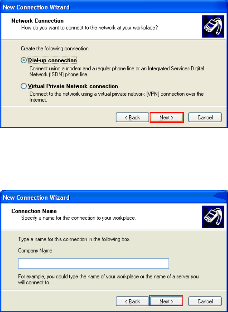
- 37 -
© QuestLabs Limited
SELECT “DIAL-UP CONNECTION”. AND PRESS THE NEXT BUTTON.
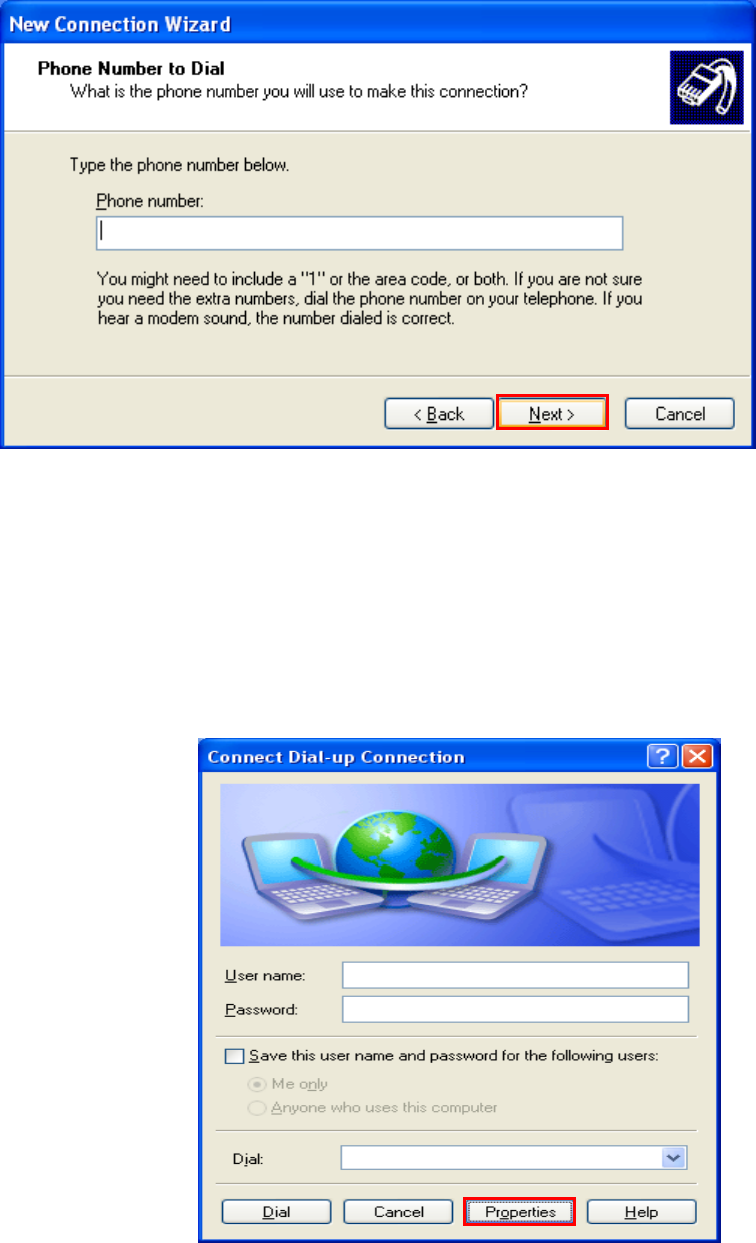
INSERT “COMPANY NAME” AS YOU WANT.
PRESS THE NEXT BUTTON.
- 38 -
© QuestLabs Limited
INSERT “PHONE NUMBER” LIST IN YOUR INTERNET ACCESS KIT AND PRESS THE NEXT BUTTON.
YOU CAN SEE A COMPLETING MESSAGE IN NEXT WINDOW.
5. CONNECT INTERNET
GO TO THE “NETWORK CONNECTIONS” MENU.
START BUTTON > CONTROL PANEL > NETWORK AND INTERNET CONNECTION > NETWORK
CONNECTIONS
AND CHOOSE THE CONNECTION NAME WHICH WAS CREATED IN THE DIAL-UP CONNECTION.
SELECT “PROPERTIES”.
- 39 -
© QuestLabs Limited
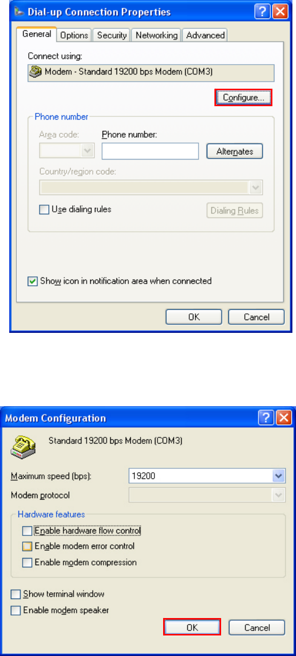
SELECT “CONFIGURE...” OF GENERAL TAB MENU.
SET AS BELOW WINDOW. AND PRESS THE OK BUTTON.
- 40 -
© QuestLabs Limited
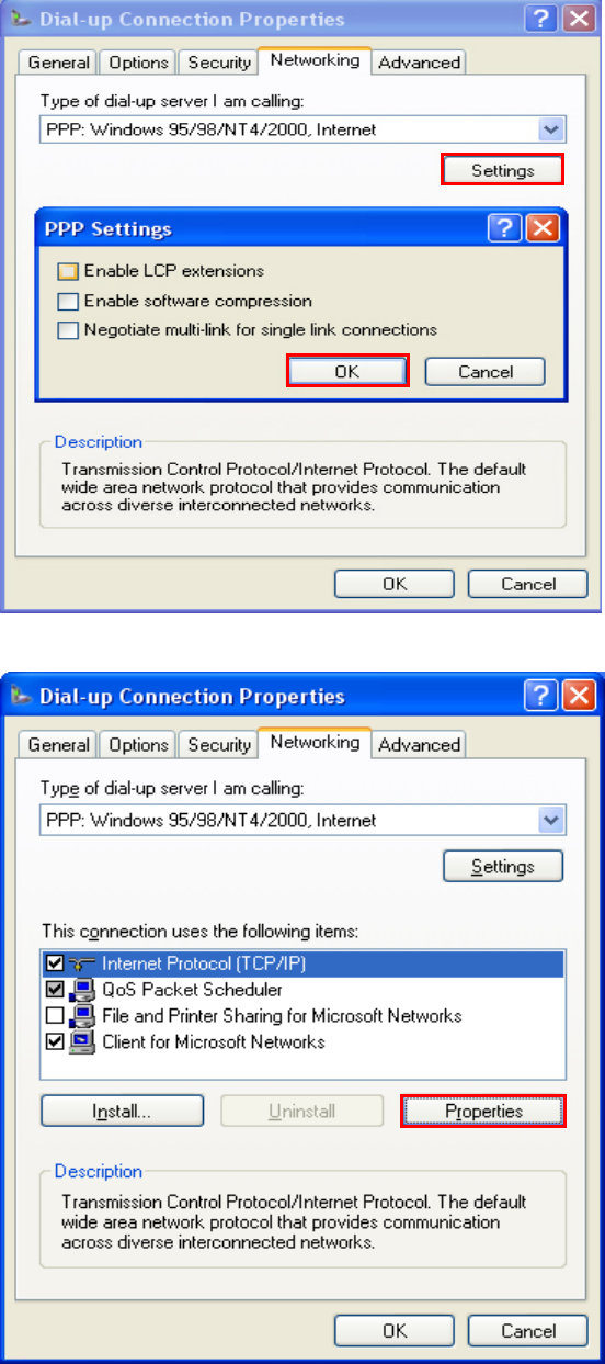
SELECT “SETTINGS” OF NETWORKING TAB MENU.
AND SET AS BELOW WINDOW. AND PRESS THE OK BUTTON.
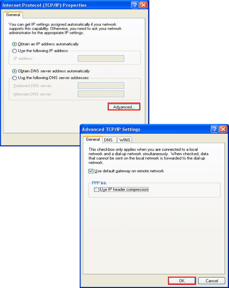
SELECT “PROPERTIES” OF INTERNET PROTOCOL (TCP/IP)
- 41 -
© QuestLabs Limited
SELECT “ADVANCED...”.
AND SET AS BELOW WINDOW. AND PRESS THE OK BUTTON.
- 42 -
© QuestLabs Limited
PRESS OK BUTTON AND RETURN TO THE “CONNECT DIAL-UP CONNECTION” WINDOW.
WHEN YOU WANT THE CSD (DIAL-UP) DATA CONNECTION,
YOU CAN FIND USERNAME, PASSWORD, DIAL NUMBER FROM THE INTERNET ACCESS KIT THAT
YOU PURCHASED. AFTER FILLING THOSE VALUES, PRESS THE DIAL BUTTON.
WHEN YOU WANT THE GPRS DATA CONNECTION,
IF YOUR NETWORK SERVICE PROVIDER HAS THE RECOMMEND SETTING OR THE ACCESS
PROGRAM, YOU SHOULD USE THAT.
IF NOT, YOU DON’T NEED TO INPUT USERNAME, PASSWORD. JUST INPUT A DIAL NUMBER AS “*99#”.
AND PRESS THE DIAL BUTTON.