Axesstel TX241G CDMA Fixed Wireless Terminal User Manual User ID and Password
Axesstel Inc CDMA Fixed Wireless Terminal User ID and Password
UserManual.wiki
>
Axesstel
>
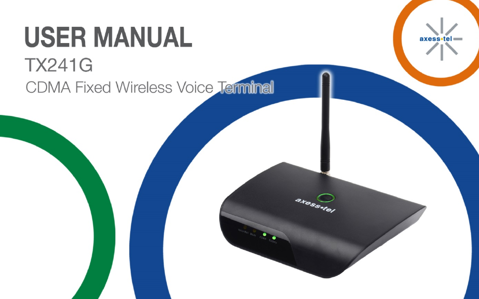
TX241G User Manual
User Manual
Navigation menu
Upload a User Manual
Namespaces
Wiki Guide
HTML
PDF
Info
Views
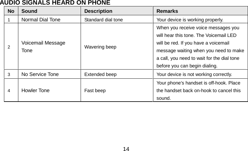
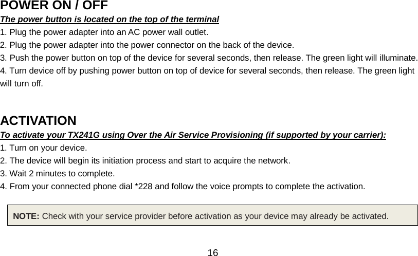
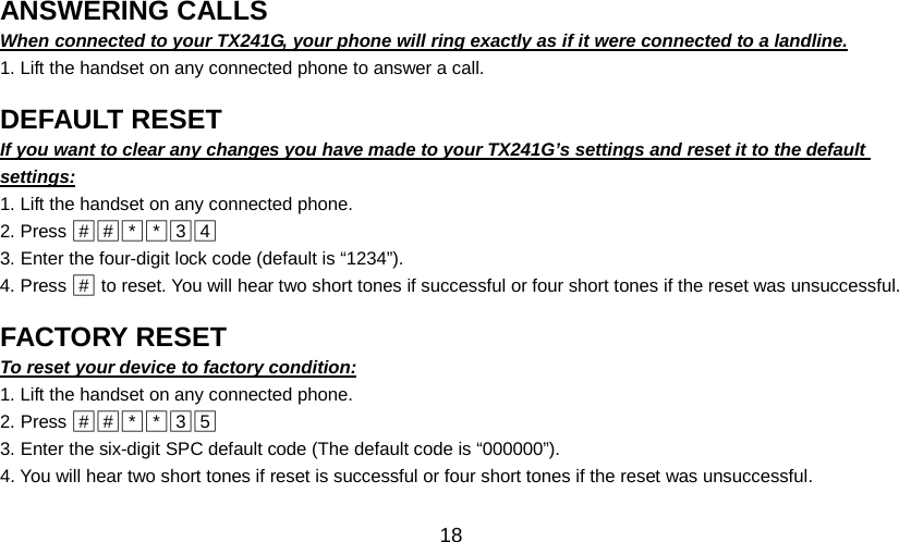
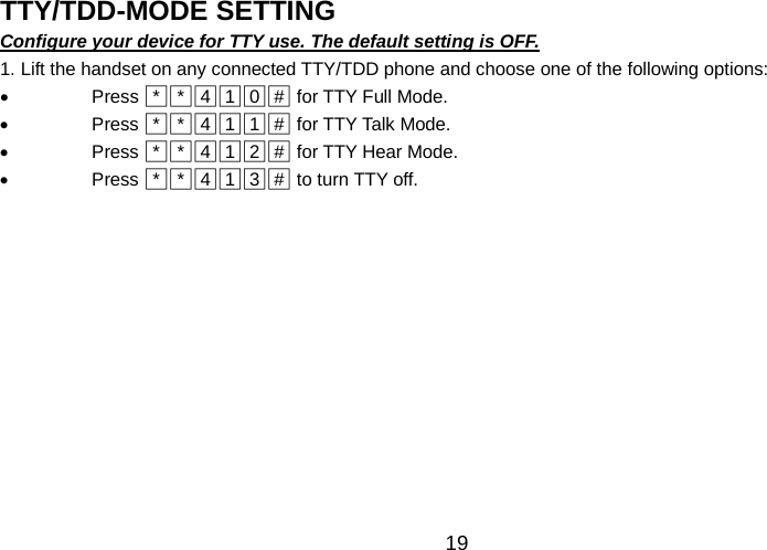
User Manual
Discussion / Help
Navigation