Axesstel TX241G CDMA Fixed Wireless Terminal User Manual User ID and Password
Axesstel Inc CDMA Fixed Wireless Terminal User ID and Password
Axesstel >
User Manual
1
2
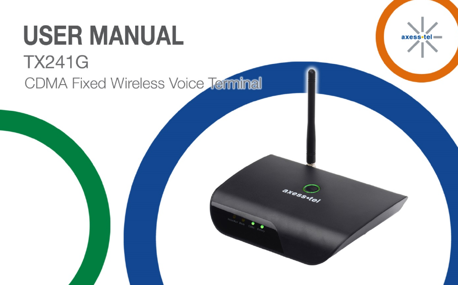
INTRODUCTION
OVERVIEW
The Axesstel TX241G is a dual-band (800/1900Mhz) fixed wireless voice terminal that is perfect for
consumers searching for a seamless POTS (Plain Old Telephone Service) land-line replacement
service. TX241G is designed to provide a simple, cost effective dial tone service at a home or
business. The TX241G is powered by an AC adapter with a 1600mAh rechargeable battery backup
to provide continued functionality in the event of a power outage. Its advanced Assisted GPS
(AGPS) feature provides E911 service to accurately determine the location of the caller in case of
an emergency. Axesstel’s TX241G also allows the consumer to migrate from landline to cellular
without losing any functionality of their regular home phone service.
3
FEATURES
- CDMA2000 1x-Advanced Voice Services (backward compatible to IS-95 A/B)
- 800/1900 MHz Dual Band
- OMA-DM HFA Activation and FUMO Support
- AGPS for E911 Service Support
- TTY/TDD Telephone Support
- 5 Multiple LED Indicators (Power, Battery, Voicemail Waiting Indicator, Mode, CDMA)
- 2 RJ-11 Bridged Ports to Connect to POTS Phones
- Dial-Tone and DTMF Generation
- Call Waiting, Three-way Calling, Call Forwarding, and Hook Flash
- Call Restriction, Caller ID, and Call Waiting Caller ID
- Rechargeable 1600mAh Li-ion Backup Battery
- USB Diagnostic Port for Firmware Upgrades
- OTA(IS-683A)
4
TABLE OF CONTENTS
INTRODUCTION
2
Setting Up Your Voicemail
17
Overview
2
Making Callls
17
Features
3
Answering Calls
18
Safety Precautions
5
Default Reset
18
Package Contents
7
Factory Reset
18
TTY/TDD-Mode Setting
19
BASIC INSTALLATION
9
Battery Installation
9
OPTIONAL FEATURES
20
Setting Up The Device
10
Caller ID
21
E911 Information
11
Setting Caller ID Mode
21
Call Waiting
21
GETTING TO KNOW THE TERMINAL
12
3-Way Calling
22
LED Indicator Lights
12
Audio Signals Heard On Phone
14
MISCELLANEOUS
23
Troubleshooting
24
BASIC OPERATION
15
Specifications
26
Power On/Off
16
Safety Information
28
Activation
16
5
SAFETY PRECAUTIONS
1. Avoid placing the terminal in a dusty location, or near a source of gas or fire.
2. Do not shake, hit or drop the terminal.
3. To clean the outside of the terminal, use only a soft, dry cloth, as chemicals such as alcohol,
benzene or acetone can damage the surface of the terminal.
4. Do not twist or pull the cables.
5. Do not disassemble the terminal.
6. Do not use the power adapter if:
- The power cord is damaged.
- The adapter has been damaged in any way.
7. Use only the AXESSTEL provided power adapter. Do not use the AXESSTEL power adapter for
any other purpose.
8. Use only the AXESSTEL provided antenna. Do not use the antenna for any other purpose.
9. Frequency and length of use can affect the life of the self-charging battery. Contact your point of
sale’s customer service department if the battery is not operating properly.
10. Use only the designated self-charging battery. Dispose of exhausted batteries properly.
Never discard a battery in or near a fire or flame.

6
11. Do not use the terminal near water, for example, near a bathtub, sink, wet basement, or swimming
pool.
NOTE:
The input voltage and the shape of the power plug may vary from country to country.
NOTE: Use wired or cordless telephones compatible to FCC part 68 only. Non-compliant
telephones may not work properly.

7
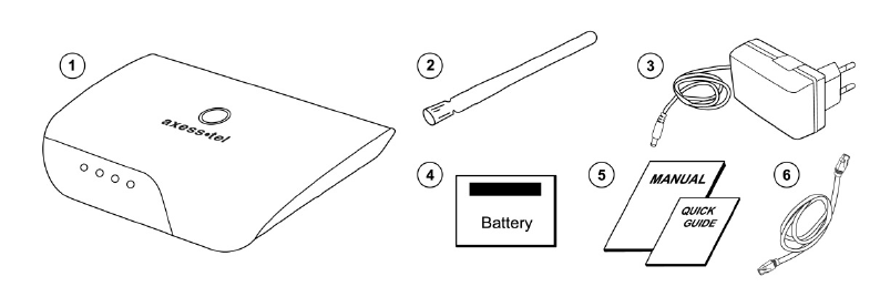
PACKAGE CONTENTS
After opening the package, check to make sure that you have all the parts shown below.
If any item is missing or broken, please call your service provider’s support center.
①
Axesstel 1x-Advanced Fixed Wireless Terminal
②
CDMA Dipole Antenna
③
Power Adapter (Input: AC100-240V, 50/60Hz / Output:5V/2A)
④
Backup Battery
⑤
User Manual and Quick Guide
⑥
RJ-11 Phone Cord
CAUTION
Use only the power adapter provided. Using another power adapter may cause
permanent damage to your terminal.
8
9
BASIC INSTALLATION
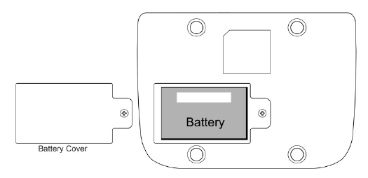
BATTERY INSTALLATION
The TX241G operates on either AC current or its internal battery. However, you should use AC power whenever
possible, reserving the battery for power outages.
1. Open the battery cover on the bottom of the device.
2. Insert the battery into the device.
3. Insert the battery pack in the right position with the battery terminals making contact with the device terminals.
4. Close the battery cover.
10
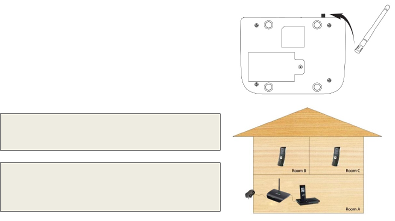
SETTING UP THE DEVICE
1. Connect the antenna by screwing it into
the connector on the back of the device.
2. Connect a wired or cordless telephone to the
device using the supplied RJ-11 phone cord.
3. Plug the power adapter cable into the device.
4. Plug the power adapter into an AC power wall outlet.
WARNING: Do not connect this device to your telephone
wall outlet. This configuration is not supported unless you
have taken steps to disconnect existing landline wiring
coming into your home or office.
NOTE: Use only wired or cordless telephones that conform
to FCC part 68 requirements. Non-compliant telephones
may not work properly.

11
E911 INFORMATION
Your device features an embedded Global Positioning System (GPS) chip necessary for utilizing E911
emergency location services where available. During the emergency call, all the LEDs on the terminal will blink
and your location can then be determined by the 911 operator.
IMPORTANT: Always report your location to the 911 operator when placing an emergency call. Some
designated emergency call takers, known as Public Safety Answering Points (PSAPs) may not be
equipped to receive GPS location information from your device.
12
GETTING TO KNOW THE TERMINAL
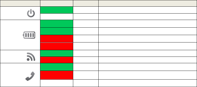
LED INDICATOR LIGHTS
Item
Color
Status
Description
POWER
Green
Solid
On
Off
-
Off
BATTERY
Green
Solid Battery is sole source, power above mid-voltage
Green
Blinking AC is sole source, battery charging
Red Solid Battery is sole source, voltage low
Red
Blinking
AC is sole source, no battery
CDMA
Green
Solid
Camped on network
Red
Solid
No CDMA coverage
MODE
Green Solid Incoming call
Red Solid Off-hook
Off - On-hook
13
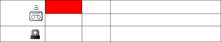
VOICEMAIL
Red Solid Voicemail in the system
Off - No new voicemail
E911 Call
All LEDs Blinking All LEDs blink during emergency call

14
AUDIO SIGNALS HEARD ON PHONE
No
Sound
Description
Remarks
1
Normal Dial Tone
Standard dial tone
Your device is working properly.
2 Voicemail Message
Tone Wavering beep
When you receive voice messages you
will hear this tone. The Voicemail LED
will be red. If you have a voicemail
message waiting when you need to make
a call, you need to wait for the dial tone
before you can begin dialing.
3 No Service Tone Extended beep Your device is not working correctly.
4 Howler Tone Fast beep
Your phone’s handset is off-hook. Place
the handset back on-hook to cancel this
sound.
15
Basic Operation
POWER ON/OFF
ACTIVATION
SETTING UP YOUR VOICEMAIL
MAKING CALLS
ANSWERING CALLS
DEFAULT RESET
FACTORY RESET
TTY/TDD-MODE SETTING

16
POWER ON / OFF
The power button is located on the top of the terminal
1. Plug the power adapter into an AC power wall outlet.
2. Plug the power adapter into the power connector on the back of the device.
3. Push the power button on top of the device for several seconds, then release. The green light will illuminate.
4. Turn device off by pushing power button on top of device for several seconds, then release. The green light
will turn off.
ACTIVATION
To activate your TX241G using Over the Air Service Provisioning (if supported by your carrier):
1. Turn on your device.
2. The device will begin its initiation process and start to acquire the network.
3. Wait 2 minutes to complete.
4. From your connected phone dial *228 and follow the voice prompts to complete the activation.
NOTE: Check with your service provider before activation as your device may already be activated.
17
SETTING UP YOUR VOICEMAIL
You should set up your voicemail and personal greeting as soon as your device is activated. Always use
a password to protect against unauthorized access. Please check with your service provider for the
voicemail access number. Your device automatically transfers all unanswered calls to your voicemail,
even if your device is in use or turned off.
1. Dial your voicemail number (the phone number assigned to your phone).
2. Follow the prompts to:
• Create your password
• Record your name announcement
• Record your greeting
MAKING CALLS
1. Check if the device is turned on.
2. Lift the handset on any connected phone. You should hear a dial tone.
3. Dial a number as you usually would.
4. Wait for about 3 seconds while your device connects with the number you dialed.
NOTE: You can dial phone numbers with a maximum of 32 digits, including □
* and □
# .

18
ANSWERING CALLS
When connected to your TX241G, your phone will ring exactly as if it were connected to a landline.
1. Lift the handset on any connected phone to answer a call.
DEFAULT RESET
If you want to clear any changes you have made to your TX241G’s settings and reset it to the default
settings:
1. Lift the handset on any connected phone.
2. Press □
#□
#□
*□
*□
3
□
4
3. Enter the four-digit lock code (default is “1234”).
4. Press □
# to reset. You will hear two short tones if successful or four short tones if the reset was unsuccessful.
FACTORY RESET
To reset your device to factory condition:
1. Lift the handset on any connected phone.
2. Press □
#□
#□
*□
*□
3
□
5
3. Enter the six-digit SPC default code (The default code is “000000”).
4. You will hear two short tones if reset is successful or four short tones if the reset was unsuccessful.

19
TTY/TDD-MODE SETTING
Configure your device for TTY use. The default setting is OFF.
1. Lift the handset on any connected TTY/TDD phone and choose one of the following options:
• Press □
*□
*□
4□
1□
0□
# for TTY Full Mode.
• Press □
*□
*□
4□
1□
1□
# for TTY Talk Mode.
• Press □
*□
*□
4□
1□
2□
# for TTY Hear Mode.
• Press □
*□
*□
4□
1□
3□
# to turn TTY off.
20
Optional Features
CALLER ID
SETTING CALLER ID MODE
CALL WAITING
3-WAY CALLING

21
CALLER ID
Caller ID allows people to identify a caller before answering the phone by displaying the number of the
incoming call. If you do not want your number displayed when you make a call, follow these steps.
1. Press □
*□
6□
7
2. Enter your phone number.
SETTING CALLER ID MODE
If the phone you have connected to your TX241G has an LCD display, the caller’s number will appear by
default. To change this setting:
1. Lift the handset of any connected phone.
• Press □
*□
*□
2□
1□
0□
# to disable the Caller ID feature.
• Press □
*□
*□
2□
1□
2□
# to re-enable the Caller ID.
CALL WAITING
When you’re on a call, Call Waiting alerts you to incoming calls. To use call waiting:
1. When you hear a beep from the receiver on any connected phone during a call, it means a second caller is
trying to connect.
2. Press the hook or the flash button (if present) to answer the second call.
3. Press the hook or the flash button again to return to the first call.

22
3-WAY CALLING
With 3-Way Calling you can talk to two people at the same time. When using this feature, the normal
airtime rates will be charged for each of the two calls. To use 3-way calling:
1. Call the first party.
2. Place a second call by pressing the hook or the flash button (if present), enter the second party’s number, and
press the hook or flash button again to dial the number.
3. When you are connected to the second party, press the hook or flash button to start the 3-way call.
23
Miscellaneous
TROUBLESHOOTING
SPECIFICATIONS
SAFETY INFORMATION

24
TROUBLESHOOTING
Problem: I Can’t Place a Call
1. Check the power button to make sure your device is getting power.
2. Check the antenna to make sure it is tightly connected.
3. Check the phone cord to make sure it is properly connected.
4. Try connecting the TX241G to a different telephone.
5. If you perform all of the above steps and still can’t make a call, contact your service provider.
Problem: I Can’t Receive a Call
1. Check the power button to make sure your device is getting power.
2. Check the antenna to make sure it is tightly connected.
3. Check the phone’s handset to make sure it is seated properly on the cradle.
4. If you perform all of the above steps and still can’t receive a call, contact your service provider.
Problem: Voicemail Indicator Does Not Clear
1. If the message light stays on but you have no messages waiting, call your number and leave a voicemail.
2. Hang up, access your voicemail, and delete the message you just left

25
Problem: No Power
1. Make sure the power adapter is securely connected to both the device and the electrical outlet.
2. Make sure a back-up battery is properly installed (see Battery Installation).
3. When using in battery-only mode, make sure the back-up battery is fully charged. To view the charge level,
check the device’s Battery LED (see LED Indicator Lights).
4. Make sure the power button is turned on. The power switch is located on the top of the device.
Problem: No Signal
Follow these steps if you don’t hear a dial tone through the handset and the CDMA LED is not lit.
1. Make sure the telephone is working.
2. Check the power button to make sure your device is getting power.
3. Check the antenna to make sure it is tightly connected.
4. Next move the TX241G to another location in your home.
5. If after taking the above steps you still don’t have a dial tone and the CDMA LED is off, contact your service
provider.

26
SPECIFICATIONS
Item Description Remark
Air Interface
CDMA2000 1X-Advanced
RF Frequency 800MHz/1900Mhz Dual band
LED Indicator
- 5 Multiple LEDs
- POWER, BATTERY, VOICEMAIL WAITING INDICATOR,
MODE, and CDMA
Green, Red, Off
Interface
- 2 RJ-11 Ports (bridged), Max 4 REN
- DC power Jack
- Power ON/OFF Button
- TNC Connector for CDMA antenna with GPS antenna
Special
Feature
AGPS for E911 Service
Automatic Sending Caller ID
(DTMF, Bellcore)

27
Tone Dial, No Service, Howler, Stutter, Menu OK, Menu NOK
Call feature
Hook Flash
Call Waiting
Call Forwarding
3-Way Calling
Battery
- Li-ion rechargeable battery
- Capacity :1600mAh (Standard)
* Stand by time: 15 Hrs
* Talk time:1.5 Hr
Power Adapter - Input: AC100-240V, 50/60Hz
- Output:5V/ 2A
Dimension - Size: 174 X 128 X 34 (mm)
- Weight: 226g
With standard battery
Operating
Condition
- Operating Temperature: -25oC ~ +60oC
- Operating Humidity : 0~95%
28
SAFETY INFORMATION
This device complies with Part 15 of the FCC Rules. Its operation is subject to the following two conditions:
1. This device may not cause harmful interference, and
2. This device must accept any interference received, including interference that may cause undesired operation.
Note: This product has been tested and found to comply with the limits for a Class B digital device, pursuant to
Part 15 of the FCC Rules. These limits are designed to provide reasonable protection against harmful
interference in a residential installation. This product generates, uses, and can radiate radio frequency energy
and, if not installed and used in accordance with the instructions, may cause harmful interference to radio
communications.
However, there is no guarantee that interference will not occur in a particular installation. If this product does
cause harmful interference to radio or television reception, which can be determined by turning the equipment
off and on, the user is encouraged to try to correct the interference by one or more of the following measures:
—Reorient or relocate the receiving antenna.
—Increase the separation between the equipment and receiver.
—Connect the equipment into an outlet on a circuit different from that to which the receiver is connected.
—Consult your dealer (service provider) or an experienced radio/TV technician for help.
AXT STD V2.0
FCC Caution: Any changes or modifications not expressly approved by the
party responsible for compliance could void the user's authority to operate this
equipment.
This transmitter must not be co-located or operating in conjunction with any
other antenna or transmitter.
Radiation Exposure Statement:
This device meets the government's requirements for exposure to radio waves.
This device is designed and manufactured not to exceed the emission limits for
exposure to radio frequency (RF) energy set by the Federal Communications
Commission of the U.S. Government.
The exposure standard for wireless device employs a unit of measurement known
as the Specific Absorption Rate, or SAR.
The SAR limit set by the FCC is 1.6W/kg. *Tests for SAR are conducted using
standard operating positions accepted by the FCC with the device transmitting at
its highest certified power level in all tested frequency bands.
