Axxcelera Broand Wireless AB-ACCESS-SU01 UNII System User Manual CONTENTS

Axxcelera Broadband Wireless, Inc. UNII System CONTENTS

ADditional trouble shooting guide
        Troubleshooting-Installing anRF linkIssue : 5.3.xRev 2Authors : Matt Olson/Dave SidaDate : 30th July 2004Axxcelera Broadband Wireless175 Science ParkwayRochester, New York 14620support@axxcelera.comwww.axxcelera.com
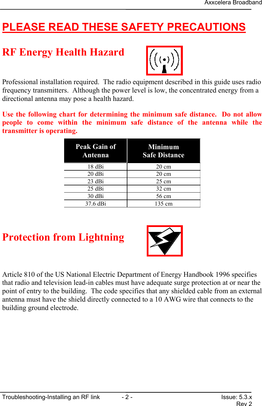
Axxcelera BroadbandTroubleshooting-Installing an RF link  - 2 - Issue: 5.3.xRev 2PLEASE READ THESE SAFETY PRECAUTIONSRF Energy Health HazardProfessional installation required.  The radio equipment described in this guide uses radiofrequency transmitters.  Although the power level is low, the concentrated energy from adirectional antenna may pose a health hazard.Use the following chart for determining the minimum safe distance.  Do not allowpeople to come within the minimum safe distance of the antenna while thetransmitter is operating.Peak Gain ofAntennaMinimumSafe Distance18 dBi 20 cm20 dBi 20 cm23 dBi 25 cm25 dBi 32 cm30 dBi 56 cm37.6 dBi 135 cmProtection from LightningArticle 810 of the US National Electric Department of Energy Handbook 1996 specifiesthat radio and television lead-in cables must have adequate surge protection at or near thepoint of entry to the building.  The code specifies that any shielded cable from an externalantenna must have the shield directly connected to a 10 AWG wire that connects to thebuilding ground electrode.
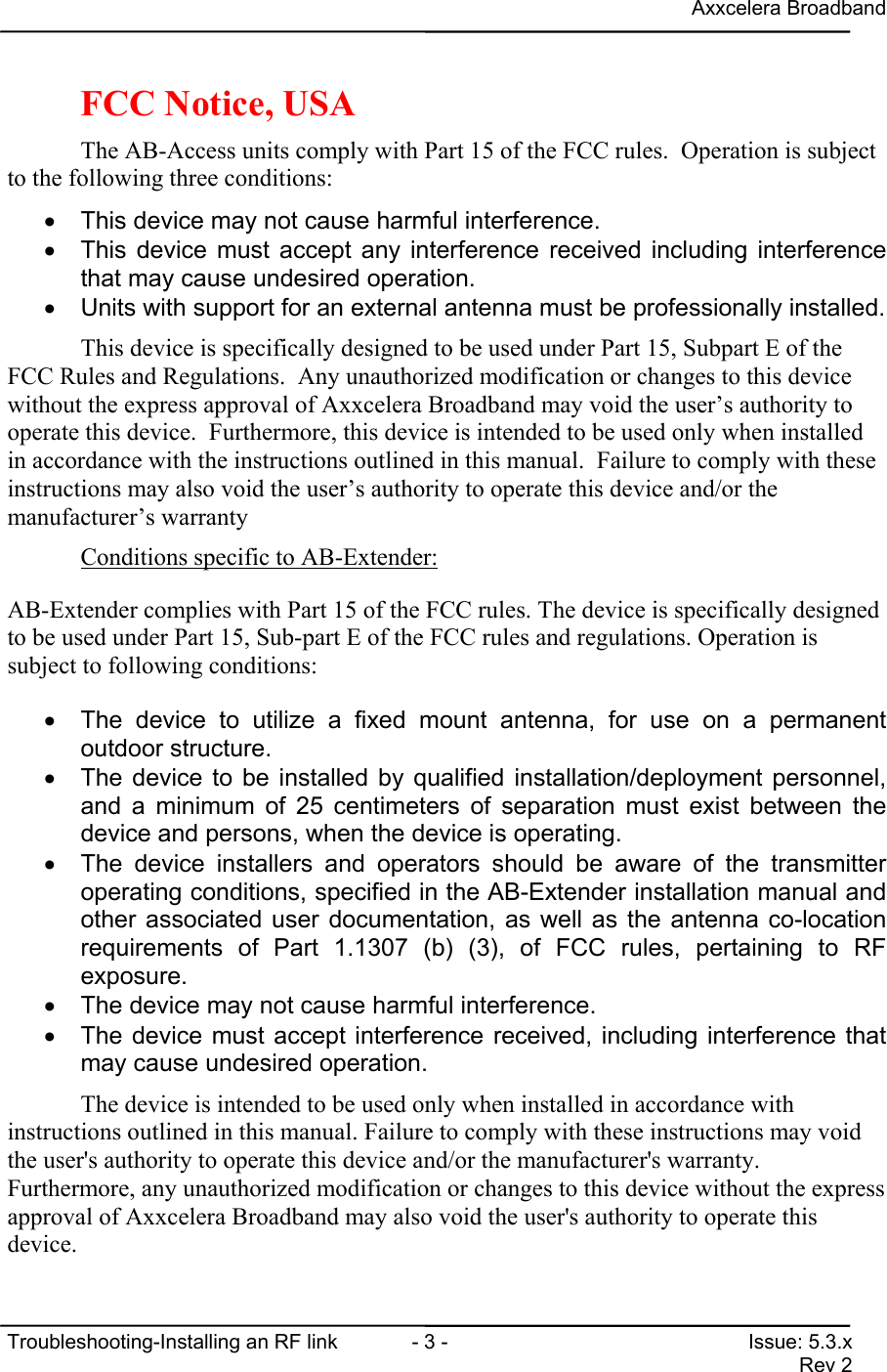
Axxcelera BroadbandTroubleshooting-Installing an RF link  - 3 - Issue: 5.3.xRev 2FCC Notice, USAThe AB-Access units comply with Part 15 of the FCC rules.  Operation is subjectto the following three conditions:•  This device may not cause harmful interference.•  This device must accept any interference received including interferencethat may cause undesired operation.•  Units with support for an external antenna must be professionally installed.This device is specifically designed to be used under Part 15, Subpart E of theFCC Rules and Regulations.  Any unauthorized modification or changes to this devicewithout the express approval of Axxcelera Broadband may void the user’s authority tooperate this device.  Furthermore, this device is intended to be used only when installedin accordance with the instructions outlined in this manual.  Failure to comply with theseinstructions may also void the user’s authority to operate this device and/or themanufacturer’s warrantyConditions specific to AB-Extender:AB-Extender complies with Part 15 of the FCC rules. The device is specifically designedto be used under Part 15, Sub-part E of the FCC rules and regulations. Operation issubject to following conditions:•  The device to utilize a fixed mount antenna, for use on a permanentoutdoor structure.•  The device to be installed by qualified installation/deployment personnel,and a minimum of 25 centimeters of separation must exist between thedevice and persons, when the device is operating.•  The device installers and operators should be aware of the transmitteroperating conditions, specified in the AB-Extender installation manual andother associated user documentation, as well as the antenna co-locationrequirements of Part 1.1307 (b) (3), of FCC rules, pertaining to RFexposure.•  The device may not cause harmful interference.•  The device must accept interference received, including interference thatmay cause undesired operation.The device is intended to be used only when installed in accordance withinstructions outlined in this manual. Failure to comply with these instructions may voidthe user's authority to operate this device and/or the manufacturer's warranty.Furthermore, any unauthorized modification or changes to this device without the expressapproval of Axxcelera Broadband may also void the user's authority to operate thisdevice.
Axxcelera BroadbandTroubleshooting-Installing an RF link  - 4 - Issue: 5.3.xRev 2CONTENTSCONTENTS ..................................................................................................................................... 41 CHANGE HISTORY................................................................................................................. 72 INTRODUCTION...................................................................................................................... 83 ALIGNING AN SU.................................................................................................................... 9LINE OF SIGHT (LOS) ..................................................................................................................... 93.1.1 Eyeball alignment................................................................................................................... 93.1.2 GPS/Compass alignment ...................................................................................................... 104 FINE TUNING AN SU ............................................................................................................ 11FINE TUNE ALIGNMENT.................................................................................................................. 114.1.1 Procedure.............................................................................................................................. 115 SU SIGNAL QUALITY ........................................................................................................... 13PROCEDURE ................................................................................................................................136 TROUBLESHOOTING SU LINK FROM AP.......................................................................... 15IDENTIFY SU ................................................................................................................................157 LINK STATUS........................................................................................................................ 17AP LINK STATUS .......................................................................................................................... 177.1.1 MAC type ............................................................................................................................. 177.1.2 Unit MAC address................................................................................................................ 177.1.3 Channel................................................................................................................................. 177.1.4 Radio Channel Mask ............................................................................................................ 177.1.5 Base Station ID..................................................................................................................... 177.1.6 Radio Temperature ............................................................................................................... 187.1.7 TX maximum backoff .......................................................................................................... 187.1.8 TX current backoff ............................................................................................................... 187.1.9 Max TX  power for channel.................................................................................................. 187.1.10 Actual TX power .................................................................................................................. 187.1.11 Averaging MAC error rates over <period> .......................................................................... 187.1.12 Aggregate Downlink Cell Error Rate ................................................................................... 187.1.13 Aggregate Uplink Cell Error Rate ........................................................................................ 18SU LINK STATUS.......................................................................................................................... 197.1.14 MAC type ............................................................................................................................. 197.1.15 Unit MAC address................................................................................................................ 197.1.16 Channel................................................................................................................................. 197.1.17 Radio Channel Mask ............................................................................................................ 207.1.18 Correlation sequence ............................................................................................................ 207.1.19 MAC delay compensation .................................................................................................... 207.1.20 Unit Range............................................................................................................................ 207.1.21 Base Station ID..................................................................................................................... 207.1.22 Radio Temperature ............................................................................................................... 20
Axxcelera BroadbandTroubleshooting-Installing an RF link  - 5 - Issue: 5.3.xRev 27.1.23 RSSI...................................................................................................................................... 207.1.24 Path loss in excess of FSL (estimate) ................................................................................... 207.1.25 Downlink RSSI Fade Margin ............................................................................................... 217.1.26 TX maximum backoff .......................................................................................................... 217.1.27 TX current backoff ............................................................................................................... 217.1.28 Max TX power for channel................................................................................................... 217.1.29 Actual TX power .................................................................................................................. 217.1.30 Averaging MAC error rates over <period> .......................................................................... 217.1.31 Downlink Header Error Rate ................................................................................................ 217.1.32 Downlink Cell Error Rate..................................................................................................... 227.1.33 Uplink Cell Error Rate.......................................................................................................... 228 MODEM RSSI ........................................................................................................................ 23SU MODEM RSSI ........................................................................................................................ 238.1.1 mean actual RX chain attenuation ........................................................................................ 238.1.2 actual RX gain ...................................................................................................................... 238.1.3 baseband gain ....................................................................................................................... 238.1.4 RSSI...................................................................................................................................... 239 MAC STATS........................................................................................................................... 24AP MAC STATS........................................................................................................................... 24DEFINITION OF TERMS................................................................................................................... 24INTERPRETING AP MAC STATS .................................................................................................... 259.1.1 FDHDR................................................................................................................................. 259.1.2 RGR...................................................................................................................................... 259.1.3 ACK...................................................................................................................................... 259.1.4 CELLS.................................................................................................................................. 269.1.5 tx........................................................................................................................................... 269.1.6 inseq...................................................................................................................................... 269.1.7 miss....................................................................................................................................... 269.1.8 dup ........................................................................................................................................ 27SU MAC STATS .......................................................................................................................... 27INTERPRETING SU MAC STATS .................................................................................................... 279.1.9 FDHDR................................................................................................................................. 279.1.10 RGR...................................................................................................................................... 289.1.11 ACK...................................................................................................................................... 289.1.12 CELLS.................................................................................................................................. 289.1.13 Tx.......................................................................................................................................... 289.1.14 inseq...................................................................................................................................... 299.1.15 miss....................................................................................................................................... 299.1.16 dup ........................................................................................................................................ 2910 MODEM TXPOWER......................................................................................................... 30AP MODEM TXPOWER .................................................................................................................. 3010.1.1 corrected FCC backoff tx attenuation................................................................................... 3010.1.2 nominal TX chain attenuation .............................................................................................. 3010.1.3 actual TX chain attenuation .................................................................................................. 3010.1.4 digital baseband attenuation ................................................................................................. 3010.1.5 nominal TX power................................................................................................................ 3010.1.6 actual TX power ................................................................................................................... 31SU MODEM TXPOWER.................................................................................................................. 3110.1.7 corrected FCC backoff tx attenuation................................................................................... 31
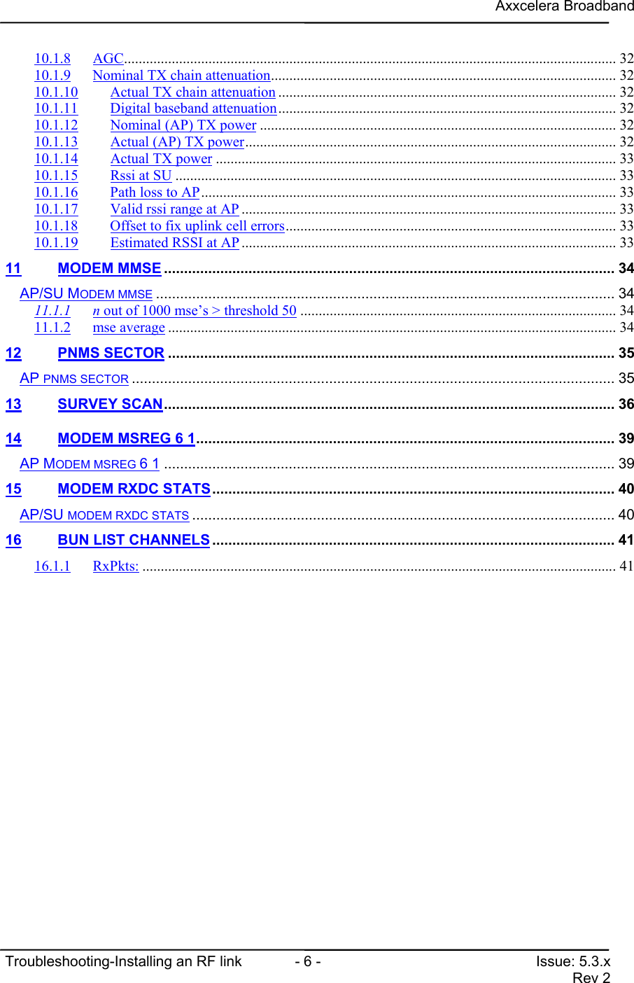
Axxcelera BroadbandTroubleshooting-Installing an RF link  - 6 - Issue: 5.3.xRev 210.1.8 AGC...................................................................................................................................... 3210.1.9 Nominal TX chain attenuation.............................................................................................. 3210.1.10 Actual TX chain attenuation ............................................................................................ 3210.1.11 Digital baseband attenuation............................................................................................ 3210.1.12 Nominal (AP) TX power ................................................................................................. 3210.1.13 Actual (AP) TX power..................................................................................................... 3210.1.14 Actual TX power ............................................................................................................. 3310.1.15 Rssi at SU ........................................................................................................................ 3310.1.16 Path loss to AP................................................................................................................. 3310.1.17 Valid rssi range at AP ...................................................................................................... 3310.1.18 Offset to fix uplink cell errors.......................................................................................... 3310.1.19 Estimated RSSI at AP...................................................................................................... 3311 MODEM MMSE ................................................................................................................ 34AP/SU MODEM MMSE .................................................................................................................. 3411.1.1 n out of 1000 mse’s > threshold 50 ...................................................................................... 3411.1.2 mse average .......................................................................................................................... 3412 PNMS SECTOR ............................................................................................................... 35AP PNMS SECTOR ........................................................................................................................ 3513 SURVEY SCAN................................................................................................................ 3614 MODEM MSREG 6 1........................................................................................................ 39AP MODEM MSREG 6 1 ................................................................................................................ 3915 MODEM RXDC STATS.................................................................................................... 40AP/SU MODEM RXDC STATS ......................................................................................................... 4016 BUN LIST CHANNELS.................................................................................................... 4116.1.1 RxPkts: ................................................................................................................................. 41
Axxcelera BroadbandTroubleshooting-Installing an RF link  - 7 - Issue: 5.3.xRev 21 CHANGE HISTORYREVISION DATE EDITOR DESCRIPTIONDraft 1 14th Aug 2002 MOlson First DraftDraft 2 5th Nov 2002 DSida Edits to section 3 (link status)Draft 3 15th Nov 2002 MOlson Numerous updatesDraft 4 20th Nov 2002 DSida Edits to sections 7,8,9Draft 5 2nd Dec 2002 DSida Edits to sections 4,5,6Draft 6 31st Mar 2003 MOlson Updates for 5.2.x releaseDraft 7 29th Apr 2004 Molson Updates for 5.3.65.3.x, Rev 2 30th July 2004 JHiggs Updated to include FCC and safety information
Axxcelera BroadbandTroubleshooting-Installing an RF link  - 8 - Issue: 5.3.xRev 22 INTRODUCTIONThis document’s purpose is to help troubleshoot radio problems with the AB-Access andAB-Extender products. This document should only be used with System Software 5.1.5or above, because some of the CLI commands described here are either different or notsupported by earlier software revisions.
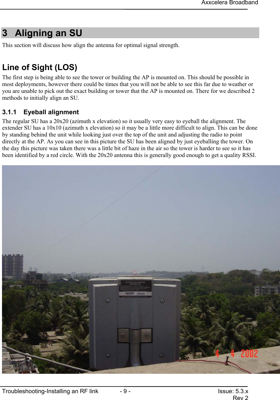
Axxcelera BroadbandTroubleshooting-Installing an RF link  - 9 - Issue: 5.3.xRev 23  Aligning an SUThis section will discuss how align the antenna for optimal signal strength.Line of Sight (LOS)The first step is being able to see the tower or building the AP is mounted on. This should be possible inmost deployments, however there could be times that you will not be able to see this far due to weather oryou are unable to pick out the exact building or tower that the AP is mounted on. There for we described 2methods to initially align an SU.3.1.1 Eyeball alignmentThe regular SU has a 20x20 (azimuth x elevation) so it usually very easy to eyeball the alignment. Theextender SU has a 10x10 (azimuth x elevation) so it may be a little more difficult to align. This can be doneby standing behind the unit while looking just over the top of the unit and adjusting the radio to pointdirectly at the AP. As you can see in this picture the SU has been aligned by just eyeballing the tower. Onthe day this picture was taken there was a little bit of haze in the air so the tower is harder to see so it hasbeen identified by a red circle. With the 20x20 antenna this is generally good enough to get a quality RSSI.
Axxcelera BroadbandTroubleshooting-Installing an RF link  - 10 - Issue: 5.3.xRev 23.1.2 GPS/Compass alignmentA GPS (Global Positioning System) can be used to align the unit by taking a waypoint at the AP. This willallow you to get the proper bearing to the AP from the building the SU is on. Then by holding the GPS nextthe SU you can turn the SU to the proper bearing. This can also be done with a compass if the bearing hasbeen defined by looking at a map. Or if the installer knows the general direction of the Access Point.Note:When purchasing a GPS make sure it has a digital compass, because if it doesn’t the GPS compass is notaccurate unless you are moving.
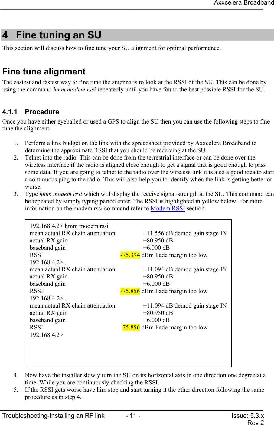
Axxcelera BroadbandTroubleshooting-Installing an RF link  - 11 - Issue: 5.3.xRev 24  Fine tuning an SUThis section will discuss how to fine tune your SU alignment for optimal performance.Fine tune alignmentThe easiest and fastest way to fine tune the antenna is to look at the RSSI of the SU. This can be done byusing the command hmm modem rssi repeatedly until you have found the best possible RSSI for the SU.4.1.1 ProcedureOnce you have either eyeballed or used a GPS to align the SU then you can use the following steps to finetune the alignment.1. Perform a link budget on the link with the spreadsheet provided by Axxcelera Broadband todetermine the approximate RSSI that you should be receiving at the SU.2. Telnet into the radio. This can be done from the terrestrial interface or can be done over thewireless interface if the radio is aligned close enough to get a signal that is good enough to passsome data. If you are going to telnet to the radio over the wireless link it is also a good idea to starta continuous ping to the radio. This will also help you to identify when the link is getting better orworse.3. Type hmm modem rssi which will display the receive signal strength at the SU. This command canbe repeated by simply typing period enter. The RSSI is highlighted in yellow below. For moreinformation on the modem rssi command refer to Modem RSSI section.4. Now have the installer slowly turn the SU on its horizontal axis in one direction one degree at atime. While you are continuously checking the RSSI.5. If the RSSI gets worse have him stop and start turning it the other direction following the sameprocedure as in step 4.192.168.4.2> hmm modem rssimean actual RX chain attenuation      +11.556 dB demod gain stage INactual RX gain                        +80.950 dBbaseband gain                         +6.000 dBRSSI                                  -75.394 dBm Fade margin too low192.168.4.2> .mean actual RX chain attenuation      +11.094 dB demod gain stage INactual RX gain                        +80.950 dBbaseband gain                         +6.000 dBRSSI                                  -75.856 dBm Fade margin too low192.168.4.2> .mean actual RX chain attenuation      +11.094 dB demod gain stage INactual RX gain                        +80.950 dBbaseband gain                         +6.000 dBRSSI                                  -75.856 dBm Fade margin too low192.168.4.2>
Axxcelera BroadbandTroubleshooting-Installing an RF link  - 12 - Issue: 5.3.xRev 26. Once you have located the bearing of the best RSSI tighten the screws that allow the radio to turnon the horizontal axis.7. Now have the installer slowly tilt the SU on the vertical axis (tilt bracket is required for verticalaxis adjustments). While you are continuously checking the RSSI.8. If the RSSI gets worse have him stop and start tilting it the other direction following the sameprocedure as in step 7.9. Once you have located the proper up tilt or down tilt on the SU for the best RSSI, tighten thescrews that allow the tilt bracket to pivot on the vertical axis.Note:If the vertical or horizontal alignment is way off when you start with step 4 you may have to try changingboth the horizontal and vertical axis at once until you can get a signal that you can start adjusting from.
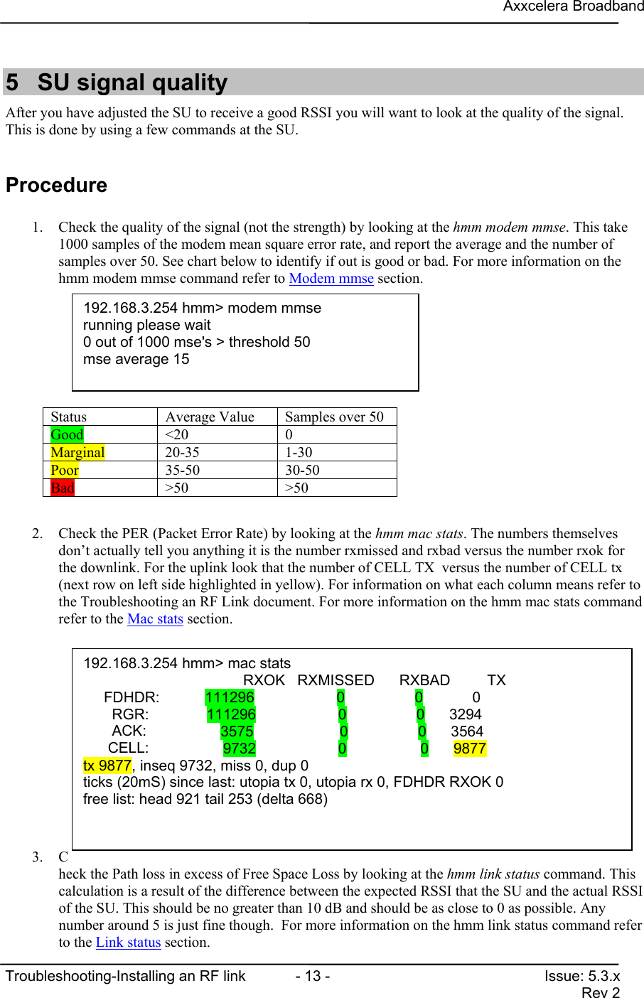
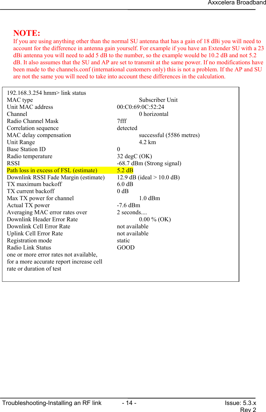
Axxcelera BroadbandTroubleshooting-Installing an RF link  - 13 - Issue: 5.3.xRev 25  SU signal qualityAfter you have adjusted the SU to receive a good RSSI you will want to look at the quality of the signal.This is done by using a few commands at the SU.Procedure1. Check the quality of the signal (not the strength) by looking at the hmm modem mmse. This take1000 samples of the modem mean square error rate, and report the average and the number ofsamples over 50. See chart below to identify if out is good or bad. For more information on thehmm modem mmse command refer to Modem mmse section.2. Check the PER (Packet Error Rate) by looking at the hmm mac stats. The numbers themselvesdon’t actually tell you anything it is the number rxmissed and rxbad versus the number rxok forthe downlink. For the uplink look that the number of CELL TX  versus the number of CELL tx(next row on left side highlighted in yellow). For information on what each column means refer tothe Troubleshooting an RF Link document. For more information on the hmm mac stats commandrefer to the Mac stats section.3. Check the Path loss in excess of Free Space Loss by looking at the hmm link status command. Thiscalculation is a result of the difference between the expected RSSI that the SU and the actual RSSIof the SU. This should be no greater than 10 dB and should be as close to 0 as possible. Anynumber around 5 is just fine though.  For more information on the hmm link status command referto the Link status section.Status Average Value Samples over 50Good <20 0Marginal 20-35 1-30Poor 35-50 30-50Bad >50 >50192.168.3.254 hmm> modem mmserunning please wait0 out of 1000 mse's > threshold 50mse average 15192.168.3.254 hmm> mac stats                  RXOK   RXMISSED      RXBAD         TX     FDHDR:           111296                    0                 0            0       RGR:              111296                    0                 0      3294       ACK:                  3575                     0                 0      3564      CELL:                  9732                    0                  0      9877tx 9877, inseq 9732, miss 0, dup 0ticks (20mS) since last: utopia tx 0, utopia rx 0, FDHDR RXOK 0free list: head 921 tail 253 (delta 668)
Axxcelera BroadbandTroubleshooting-Installing an RF link  - 14 - Issue: 5.3.xRev 2NOTE:If you are using anything other than the normal SU antenna that has a gain of 18 dBi you will need toaccount for the difference in antenna gain yourself. For example if you have an Extender SU with a 23dBi antenna you will need to add 5 dB to the number, so the example would be 10.2 dB and not 5.2dB. It also assumes that the SU and AP are set to transmit at the same power. If no modifications havebeen made to the channels.conf (international customers only) this is not a problem. If the AP and SUare not the same you will need to take into account these differences in the calculation.192.168.3.254 hmm> link statusMAC type                                   Subscriber UnitUnit MAC address                                 00:C0:69:0C:52:24Channel                                    0 horizontalRadio Channel Mask                     7fffCorrelation sequence                   detectedMAC delay compensation                     successful (5586 metres)Unit Range                                 4.2 kmBase Station ID                        0Radio temperature                      32 degC (OK)RSSI                                       -68.7 dBm (Strong signal)Path loss in excess of FSL (estimate)  5.2 dBDownlink RSSI Fade Margin (estimate)   12.9 dB (ideal > 10.0 dB)TX maximum backoff                     6.0 dBTX current backoff                     0 dBMax TX power for channel                   1.0 dBmActual TX power                        -7.6 dBmAveraging MAC error rates over         2 seconds....Downlink Header Error Rate                 0.00 % (OK)Downlink Cell Error Rate               not availableUplink Cell Error Rate                 not availableRegistration mode                      staticRadio Link Status                      GOODone or more error rates not available,for a more accurate report increase cellrate or duration of test
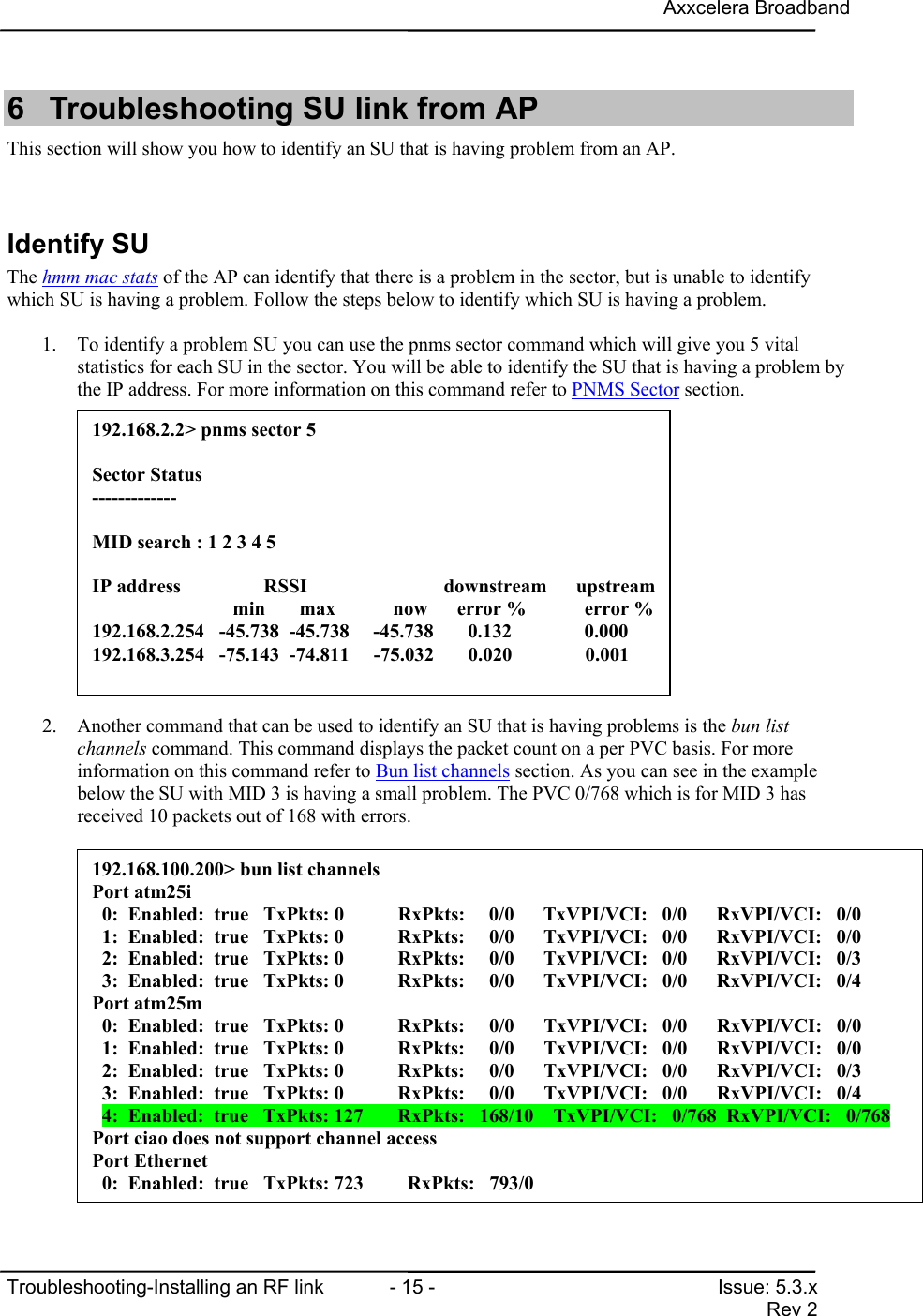
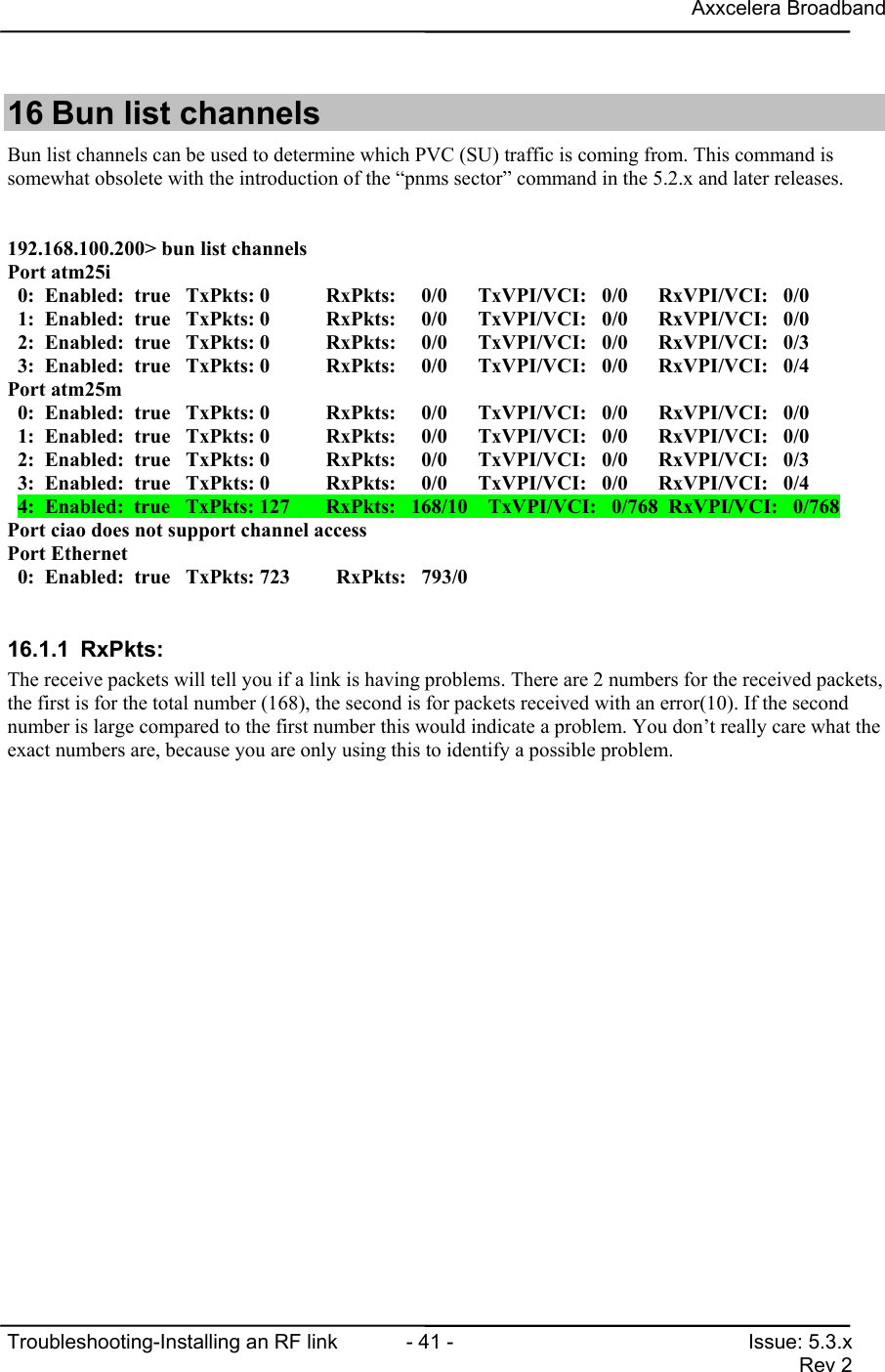
Axxcelera BroadbandTroubleshooting-Installing an RF link  - 15 - Issue: 5.3.xRev 26  Troubleshooting SU link from APThis section will show you how to identify an SU that is having problem from an AP.Identify SUThe hmm mac stats of the AP can identify that there is a problem in the sector, but is unable to identifywhich SU is having a problem. Follow the steps below to identify which SU is having a problem.1. To identify a problem SU you can use the pnms sector command which will give you 5 vitalstatistics for each SU in the sector. You will be able to identify the SU that is having a problem bythe IP address. For more information on this command refer to PNMS Sector section.2. Another command that can be used to identify an SU that is having problems is the bun listchannels command. This command displays the packet count on a per PVC basis. For moreinformation on this command refer to Bun list channels section. As you can see in the examplebelow the SU with MID 3 is having a small problem. The PVC 0/768 which is for MID 3 hasreceived 10 packets out of 168 with errors.192.168.2.2> pnms sector 5Sector Status-------------MID search : 1 2 3 4 5IP address                 RSSI             downstream      upstream                   min       max           now      error %            error %192.168.2.254   -45.738  -45.738   -45.738       0.132     0.000192.168.3.254   -75.143  -74.811     -75.032       0.020               0.001192.168.100.200> bun list channelsPort atm25i  0:  Enabled:  true   TxPkts: 0           RxPkts:     0/0      TxVPI/VCI:   0/0      RxVPI/VCI:   0/0  1:  Enabled:  true   TxPkts: 0           RxPkts:     0/0      TxVPI/VCI:   0/0      RxVPI/VCI:   0/0  2:  Enabled:  true   TxPkts: 0           RxPkts:     0/0      TxVPI/VCI:   0/0      RxVPI/VCI:   0/3  3:  Enabled:  true   TxPkts: 0           RxPkts:     0/0      TxVPI/VCI:   0/0      RxVPI/VCI:   0/4Port atm25m  0:  Enabled:  true   TxPkts: 0           RxPkts:     0/0      TxVPI/VCI:   0/0      RxVPI/VCI:   0/0  1:  Enabled:  true   TxPkts: 0           RxPkts:     0/0      TxVPI/VCI:   0/0      RxVPI/VCI:   0/0  2:  Enabled:  true   TxPkts: 0           RxPkts:     0/0      TxVPI/VCI:   0/0      RxVPI/VCI:   0/3  3:  Enabled:  true   TxPkts: 0           RxPkts:     0/0      TxVPI/VCI:   0/0      RxVPI/VCI:   0/4  4:  Enabled:  true   TxPkts: 127       RxPkts:   168/10    TxVPI/VCI:   0/768  RxVPI/VCI:   0/768Port ciao does not support channel accessPort Ethernet  0:  Enabled:  true   TxPkts: 723         RxPkts:   793/0
Axxcelera BroadbandTroubleshooting-Installing an RF link  - 16 - Issue: 5.3.xRev 23. Once you have identified the SU you can focus on troubleshooting that particular SU.  Refer tosection  Fine tuning an SU and SU signal quality for pointers on what to look for whiletroubleshooting an SU.
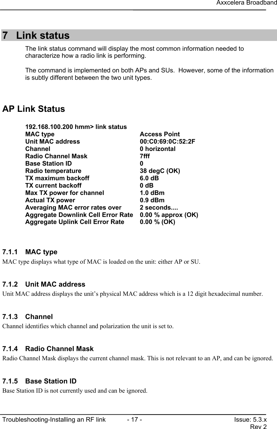
Axxcelera BroadbandTroubleshooting-Installing an RF link  - 17 - Issue: 5.3.xRev 27 Link statusThe link status command will display the most common information needed tocharacterize how a radio link is performing.The command is implemented on both APs and SUs.  However, some of the informationis subtly different between the two unit types.AP Link Status192.168.100.200 hmm> link statusMAC type                               Access PointUnit MAC address                       00:C0:69:0C:52:2FChannel                                0 horizontalRadio Channel Mask                     7fffBase Station ID                        0Radio temperature                      38 degC (OK)TX maximum backoff                     6.0 dBTX current backoff                     0 dBMax TX power for channel               1.0 dBmActual TX power                        0.9 dBmAveraging MAC error rates over        2 seconds....Aggregate Downlink Cell Error Rate 0.00 % approx (OK)Aggregate Uplink Cell Error Rate       0.00 % (OK)7.1.1 MAC typeMAC type displays what type of MAC is loaded on the unit: either AP or SU.7.1.2  Unit MAC addressUnit MAC address displays the unit’s physical MAC address which is a 12 digit hexadecimal number.7.1.3 ChannelChannel identifies which channel and polarization the unit is set to.7.1.4  Radio Channel MaskRadio Channel Mask displays the current channel mask. This is not relevant to an AP, and can be ignored.7.1.5  Base Station IDBase Station ID is not currently used and can be ignored.
Axxcelera BroadbandTroubleshooting-Installing an RF link  - 18 - Issue: 5.3.xRev 27.1.6 Radio TemperatureRadio Temperature displays the internal temperature of the radio in degrees Celsius. It is followed by anindicator to tell you if the temperature is acceptable. Possible indicators are good, marginal and bad.7.1.7  TX maximum backoffTX maximum backoff displays the maximum system backoff that can be placed in the system.conf file fora given band.7.1.8  TX current backoffTX current backoff displays the system backoff that is currently in the unit. This number is defined by  thevalue set in the system.conf file.  Axxcelera recommend that the AP and all SUs in a sector have the samebackoff value.7.1.9  Max TX  power for channelMax TX power for channel displays the maximum power in dBm that can be transmitted from the radio.The power limits set by the FCC are; high band = +14dBm, mid band = +8dBm, low band = +1dBm.7.1.10  Actual TX powerActual TX power is the power level that the radio is actually transmitting at.  For an AP this should be veryclose, but slightly below the Max TX power value.    It should fluctuate by less than 0.5dB over time.7.1.11  Averaging MAC error rates over <period>Averaging MAC error rates over <period>, displays the number of seconds during which the MAC stats arecalculated. The default is 2 seconds, but this can be changed by adding the number of seconds desired tothe link status command (i.e. “link status 10”). Be careful not to put to large of number here because theconsole is locked while these calculations are taking place.7.1.12  Aggregate Downlink Cell Error RateAggregate Downlink Cell Error Rate is the downlink cell error rate for the entire sector. This is displayed in% and for an AP it is based on CELL TX and tx values from the AP’s MAC stats.  It is followed by anindicator to tell you if the aggregate error rate is acceptable (although individual AP-SU links may stillhave unacceptable error rates).  It is actually measuring the downstream cell retransmission rate, anddownstream cell retransmissions can be caused by either a downstream or upstream radio problem.  Fromthe AP link status command alone it is not possible to determine which AP-SU radio link/links is/arehaving a problem.  A high value for this measurement simply means that at least one radio link supportedby that AP has a problem.7.1.13  Aggregate Uplink Cell Error RateAggregate Uplink Cell Error Rate is the uplink cell error rate for the entire sector. This is displayed in %and is based on CELL RXOK, RXMISSED, and RXBAD values from the AP’s MAC stats.  It isfollowed by an indicator to tell you if the aggregate error rate is acceptable (although individual SU-APlinks may still have unacceptable error rates).   This is actually measuring the percentage of cells receivedin error, and this type of error indicates an upstream radio problem.  From the AP link status command
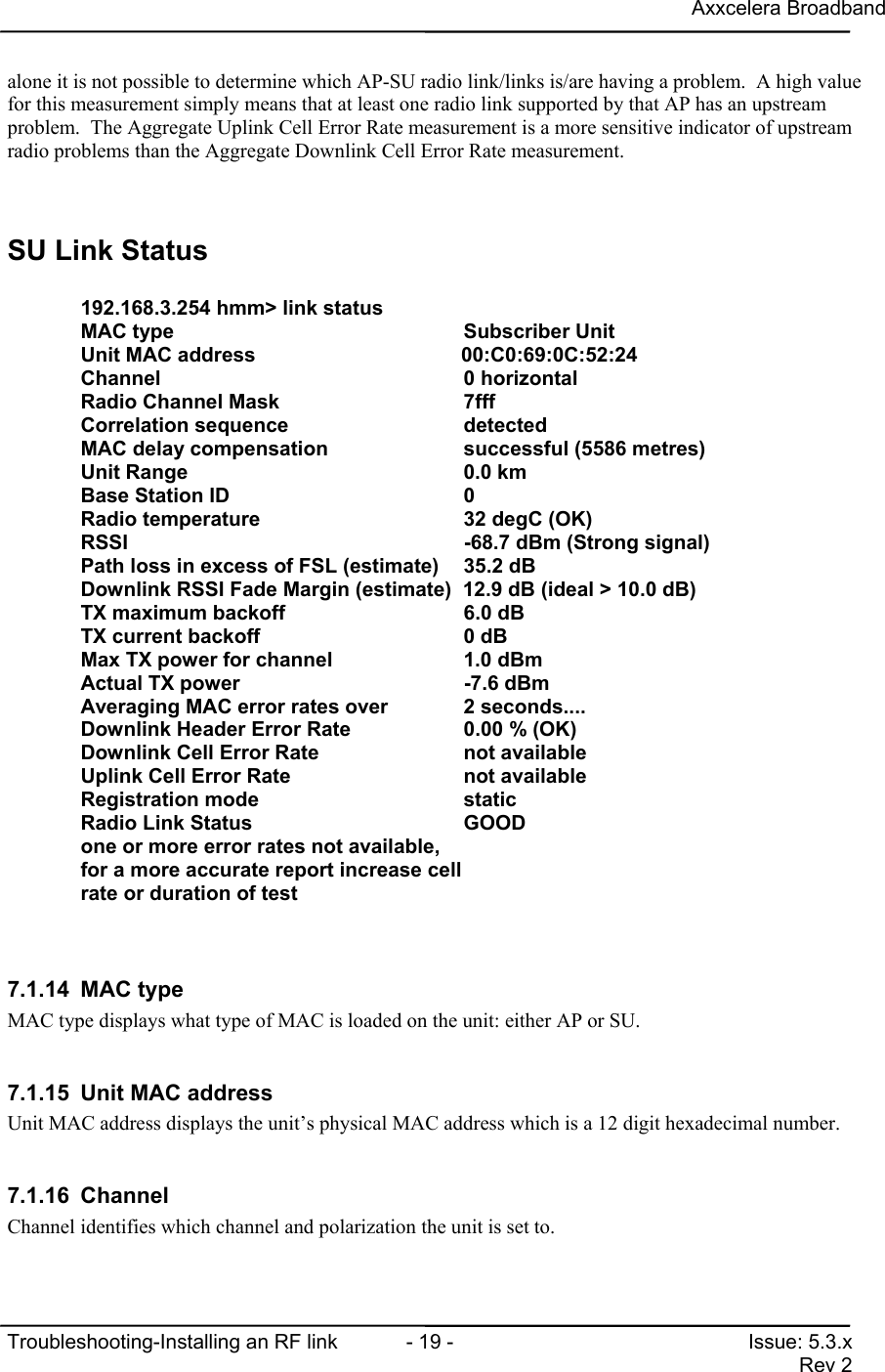
Axxcelera BroadbandTroubleshooting-Installing an RF link  - 19 - Issue: 5.3.xRev 2alone it is not possible to determine which AP-SU radio link/links is/are having a problem.  A high valuefor this measurement simply means that at least one radio link supported by that AP has an upstreamproblem.  The Aggregate Uplink Cell Error Rate measurement is a more sensitive indicator of upstreamradio problems than the Aggregate Downlink Cell Error Rate measurement.SU Link Status192.168.3.254 hmm> link statusMAC type                                  Subscriber UnitUnit MAC address                                00:C0:69:0C:52:24Channel                                   0 horizontalRadio Channel Mask                        7fffCorrelation sequence                      detectedMAC delay compensation                    successful (5586 metres)Unit Range                                0.0 kmBase Station ID                           0Radio temperature                         32 degC (OK)RSSI                                      -68.7 dBm (Strong signal)Path loss in excess of FSL (estimate)    35.2 dBDownlink RSSI Fade Margin (estimate)  12.9 dB (ideal > 10.0 dB)TX maximum backoff                        6.0 dBTX current backoff                        0 dBMax TX power for channel                  1.0 dBmActual TX power                           -7.6 dBmAveraging MAC error rates over            2 seconds....Downlink Header Error Rate                0.00 % (OK)Downlink Cell Error Rate                  not availableUplink Cell Error Rate                    not availableRegistration mode                         staticRadio Link Status                         GOODone or more error rates not available,for a more accurate report increase cellrate or duration of test7.1.14 MAC typeMAC type displays what type of MAC is loaded on the unit: either AP or SU.7.1.15  Unit MAC addressUnit MAC address displays the unit’s physical MAC address which is a 12 digit hexadecimal number.7.1.16 ChannelChannel identifies which channel and polarization the unit is set to.
Axxcelera BroadbandTroubleshooting-Installing an RF link  - 20 - Issue: 5.3.xRev 27.1.17  Radio Channel MaskRadio Channel Mask displays the current channel mask. The channel mask determines which channels willbe scanned in dynamic mode and when the survey web page is used.7.1.18 Correlation sequenceCorrelation sequence displays whether or not the SU modem has detected a downstream burst (the“training/correlation sequence”) from the AP modem. This has to happen before the MAC can delaycompensate. If the correlation sequence is un-detected you will never get a RF link.  The SU can correlateeven when the received signal is too weak to decode the rest of the burst.  Failure to correlate indicates thatthe SU cannot detect the presence of an AP.  This may be caused by the AP being off-line, an AP-SUalignment or line-of-sight problem, the AP and SU operating on different channels or polarisations, or amajor error in the SU software configuration or hardware.7.1.19  MAC delay compensationMAC delay compensation will inform you if the MAC has delay compensated. It will also display thedistance in metres that it had to back itself off to appear at the edge of the sector.  The delay compensationvalue is inversely related to the AP-SU separation.7.1.20 Unit RangeUnit Range displays the distance that the SU is from the AP in km. This measurement is based on  thedelay compensation value and is only an approximate value.7.1.21  Base Station IDBase Station ID is not currently used and can be ignored.7.1.22 Radio TemperatureRadio Temperature displays the internal temperature of the radio in degrees Celsius. It is followed by anindicator to tell you if the temperature is acceptable. Possible indicators are good, marginal and bad.7.1.23 RSSIRSSI is the Receiver Signal Strength Indicator, and is displayed in dBm. It is followed by an indicator totell you if the signal strength is acceptable.7.1.24  Path loss in excess of FSL (estimate)This shows the path loss (dB) in excess of the expected free-space loss (FSL) for the AP-SU distance.This value is approximately 0dB for a perfectly aligned AP and SU, regardless of the AP-SU distance.Although the RSSI may be strong, a high value here may indicate that the SU and AP are not well alignedand the quality of the RF link may be compromised as a result.  A value greater than 10dB should causeconcern.  Possible causes are the AP and SU set to opposight polarisations, obstructed line-of-sight, SUlying outside the main RF beam from the AP (either horizontal or vertical planes), or the SU antenna beingmisaligned with the AP.  The calculation of this value relies on the AP and SU having the same system
Axxcelera BroadbandTroubleshooting-Installing an RF link  - 21 - Issue: 5.3.xRev 2backoff, and the AP and SU having the same channels.conf file (where applicable).  A very high value herecan also indicate a hardware fault.7.1.25  Downlink RSSI Fade MarginThe Downlink RSSI fade margin is the amount by which the RSSI can fall (in dB) before the radio link willfail totally.  The minimum fade margin recommended by Axxcelera is 10dB, although units at maximumrange will have slightly less than this at best.  Although the radio link will still work, the RF error rates risesharply when the fade margin drops below approximately 5dB.  Operating SUs with a fade margin below10dB may compromise the quality of the radio link in a noisy environment.7.1.26  TX maximum backoffTX maximum backoff displays the maximum system backoff that can be placed in the system.conf file fora given band.7.1.27  TX current backoffTX current backoff displays the system backoff that is currently in the unit. This number is defined by  thevalue set in the system.conf file.  Axxcelera recommend that the AP and all SUs in a sector have the samebackoff value.7.1.28  Max TX power for channelMax TX power for channel displays the maximum power in dBm that can be transmitted from the radio.The power limits set by the FCC are; high band = +14dBm, mid band = +8dBm, low band = +1dBm.7.1.29  Actual TX powerActual TX power is the power level that the radio is actually transmitting at.  For an SU it is dependent onthe received signal strength (inversely related to RSSI), and can be anything from the Max TX power valuedown to 58dB below the Max TX power.  The value will fluctuate over time with changes in RSSI.  If theActual Tx power rises to within 2dB of the Max TX power then the RSSI on the SU is probably too low,and the upstream radio link may be unreliable at times.7.1.30  Averaging MAC error rates over <period>Averaging MAC error rates over <period>, displays the number of seconds during which the MAC stats arecalculated. The default is 2 seconds, but this can be changed by adding the number of seconds desired tothe link status command (i.e. “link status 10”). Be careful not to put to large of number here because theconsole is locked while these calculations are taking place.7.1.31  Downlink Header Error RateDownlink Header Error Rate is the FDHDR (Frame Descriptor Header) error rate for a specific AP-SUradio link. This is displayed in % and is based on FDHDR RXOK, RXMISSED, and RXBAD from theSU’s MAC stats.  It is only applicable to SUs.  It is followed by an indicator to tell you if the error rate isacceptable.  A high FDHDR error rate indicates a downstream radio problem between the AP and thisspecific SU.  It may be caused by a problem with received signal strength or quality, or a problem with theAP transmitter or SU receiver.
Axxcelera BroadbandTroubleshooting-Installing an RF link  - 22 - Issue: 5.3.xRev 27.1.32  Downlink Cell Error RateDownlink Cell Error Rate is the downlink cell error rate for a specific AP-SU radio link. This is displayedin % and is based on CELL RXOK, RXMISSED, and RXBAD from the SU’s MAC stats.  It is followedby an indicator to tell you if the error rate is acceptable.  This is actually measuring the percentage of cellsreceived in error, and this type of error indicates a downstream  radio problem.  A high downlink cell errorrate may be caused by a problem with received signal strength or quality, or a problem with the APtransmitter or SU receiver.7.1.33  Uplink Cell Error RateUplink Cell Error Rate is the uplink cell error rate for a specific SU-AP radio link. This is displayed in %and is based on CELL TX and tx from the SU’s MAC stats.  It is followed by an indicator to tell you if theerror rate is acceptable.  It is actually measuring the upstream cell retransmission rate, and upstream cellretransmissions can be caused by either an upstream or downstream radio problem.  However, theDownlink Cell Error Rate measurement is a more sensitive indicator of downstream radio problems thanthe Uplink Cell Error Rate measurement.  A high uplink cell error rate may be caused by a problem withsignal strength or quality when the signal from the SU is received by the AP, a problem with the SUtransmitter or the AP receiver, or a downlink problem.
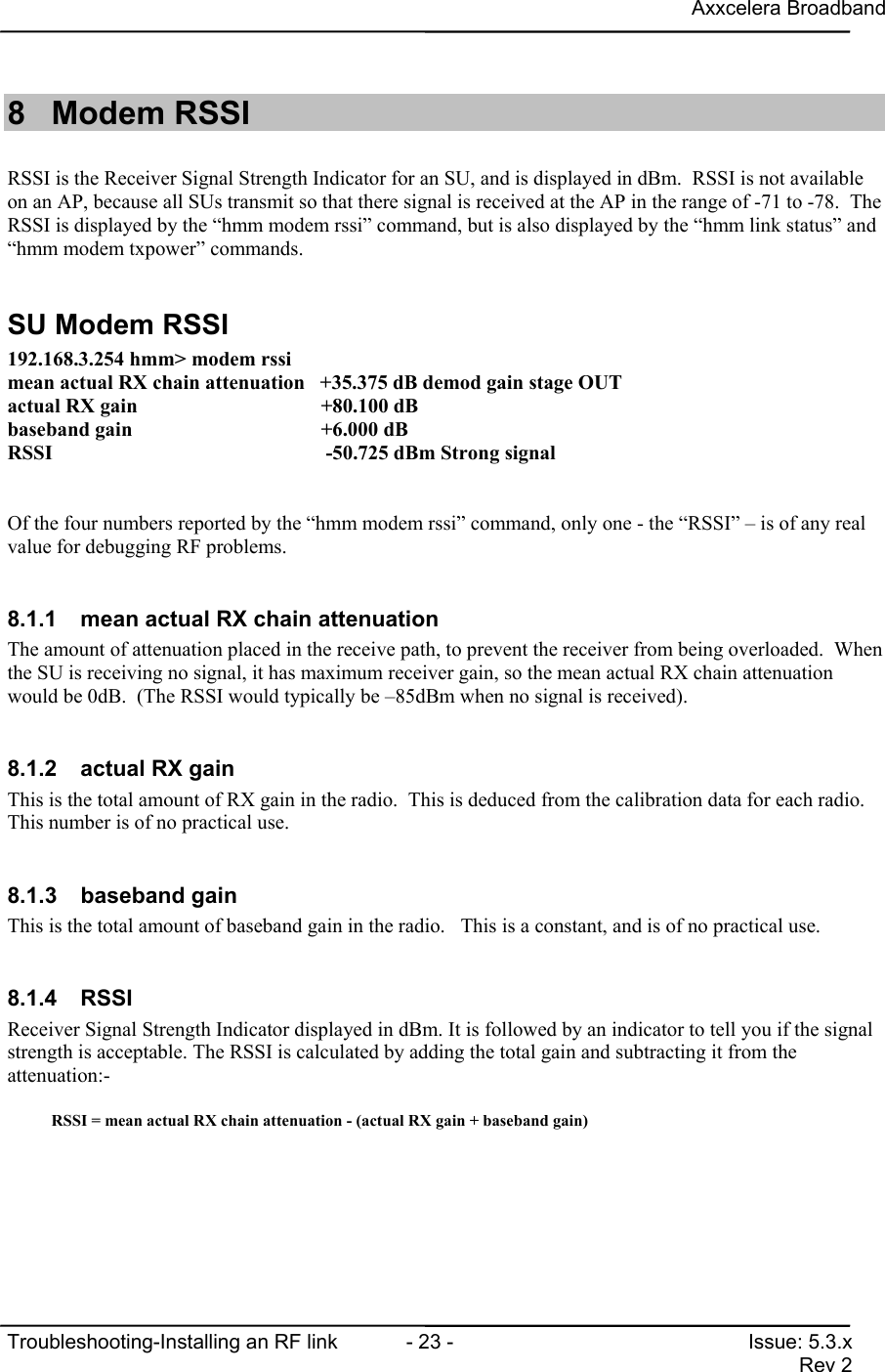
Axxcelera BroadbandTroubleshooting-Installing an RF link  - 23 - Issue: 5.3.xRev 28 Modem RSSIRSSI is the Receiver Signal Strength Indicator for an SU, and is displayed in dBm.  RSSI is not availableon an AP, because all SUs transmit so that there signal is received at the AP in the range of -71 to -78.  TheRSSI is displayed by the “hmm modem rssi” command, but is also displayed by the “hmm link status” and“hmm modem txpower” commands.SU Modem RSSI192.168.3.254 hmm> modem rssimean actual RX chain attenuation   +35.375 dB demod gain stage OUTactual RX gain                            +80.100 dBbaseband gain                             +6.000 dBRSSI                                       -50.725 dBm Strong signalOf the four numbers reported by the “hmm modem rssi” command, only one - the “RSSI” – is of any realvalue for debugging RF problems.8.1.1  mean actual RX chain attenuationThe amount of attenuation placed in the receive path, to prevent the receiver from being overloaded.  Whenthe SU is receiving no signal, it has maximum receiver gain, so the mean actual RX chain attenuationwould be 0dB.  (The RSSI would typically be –85dBm when no signal is received).8.1.2  actual RX gainThis is the total amount of RX gain in the radio.  This is deduced from the calibration data for each radio.This number is of no practical use.8.1.3 baseband gainThis is the total amount of baseband gain in the radio.   This is a constant, and is of no practical use.8.1.4 RSSIReceiver Signal Strength Indicator displayed in dBm. It is followed by an indicator to tell you if the signalstrength is acceptable. The RSSI is calculated by adding the total gain and subtracting it from theattenuation:-RSSI = mean actual RX chain attenuation - (actual RX gain + baseband gain)
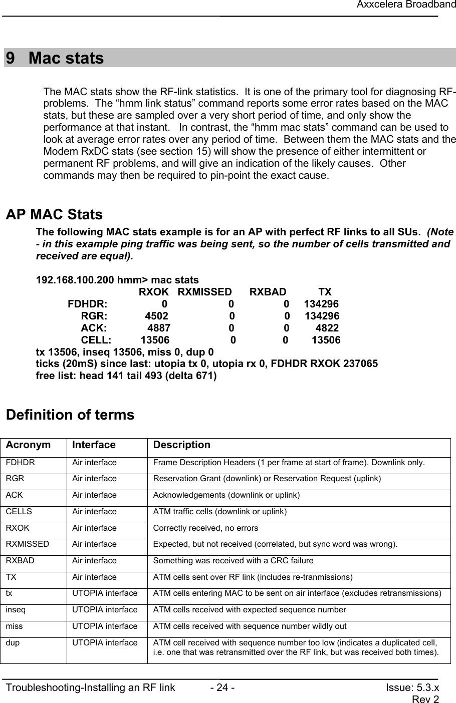
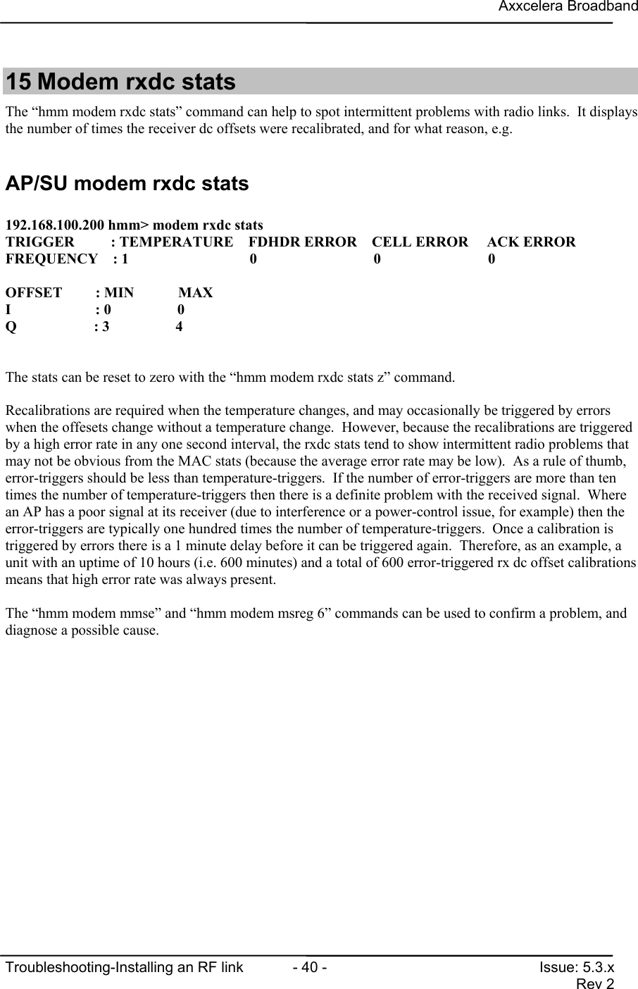
Axxcelera BroadbandTroubleshooting-Installing an RF link  - 24 - Issue: 5.3.xRev 29 Mac statsThe MAC stats show the RF-link statistics.  It is one of the primary tool for diagnosing RF-problems.  The “hmm link status” command reports some error rates based on the MACstats, but these are sampled over a very short period of time, and only show theperformance at that instant.   In contrast, the “hmm mac stats” command can be used tolook at average error rates over any period of time.  Between them the MAC stats and theModem RxDC stats (see section 15) will show the presence of either intermittent orpermanent RF problems, and will give an indication of the likely causes.  Othercommands may then be required to pin-point the exact cause.AP MAC StatsThe following MAC stats example is for an AP with perfect RF links to all SUs.  (Note- in this example ping traffic was being sent, so the number of cells transmitted andreceived are equal).192.168.100.200 hmm> mac stats                         RXOK   RXMISSED      RXBAD           TX           FDHDR:     0                     0                 0     134296        RGR:             4502                     0                 0     134296        ACK:              4887                    0                 0         4822       CELL:          13506                     0                0        13506tx 13506, inseq 13506, miss 0, dup 0ticks (20mS) since last: utopia tx 0, utopia rx 0, FDHDR RXOK 237065free list: head 141 tail 493 (delta 671)Definition of termsAcronym Interface DescriptionFDHDR Air interface Frame Description Headers (1 per frame at start of frame). Downlink only.RGR Air interface Reservation Grant (downlink) or Reservation Request (uplink)ACK Air interface Acknowledgements (downlink or uplink)CELLS Air interface ATM traffic cells (downlink or uplink)RXOK Air interface Correctly received, no errorsRXMISSED Air interface Expected, but not received (correlated, but sync word was wrong).RXBAD Air interface Something was received with a CRC failureTX Air interface ATM cells sent over RF link (includes re-tranmissions)tx UTOPIA interface ATM cells entering MAC to be sent on air interface (excludes retransmissions)inseq UTOPIA interface ATM cells received with expected sequence numbermiss UTOPIA interface ATM cells received with sequence number wildly outdup UTOPIA interface ATM cell received with sequence number too low (indicates a duplicated cell,i.e. one that was retransmitted over the RF link, but was received both times).
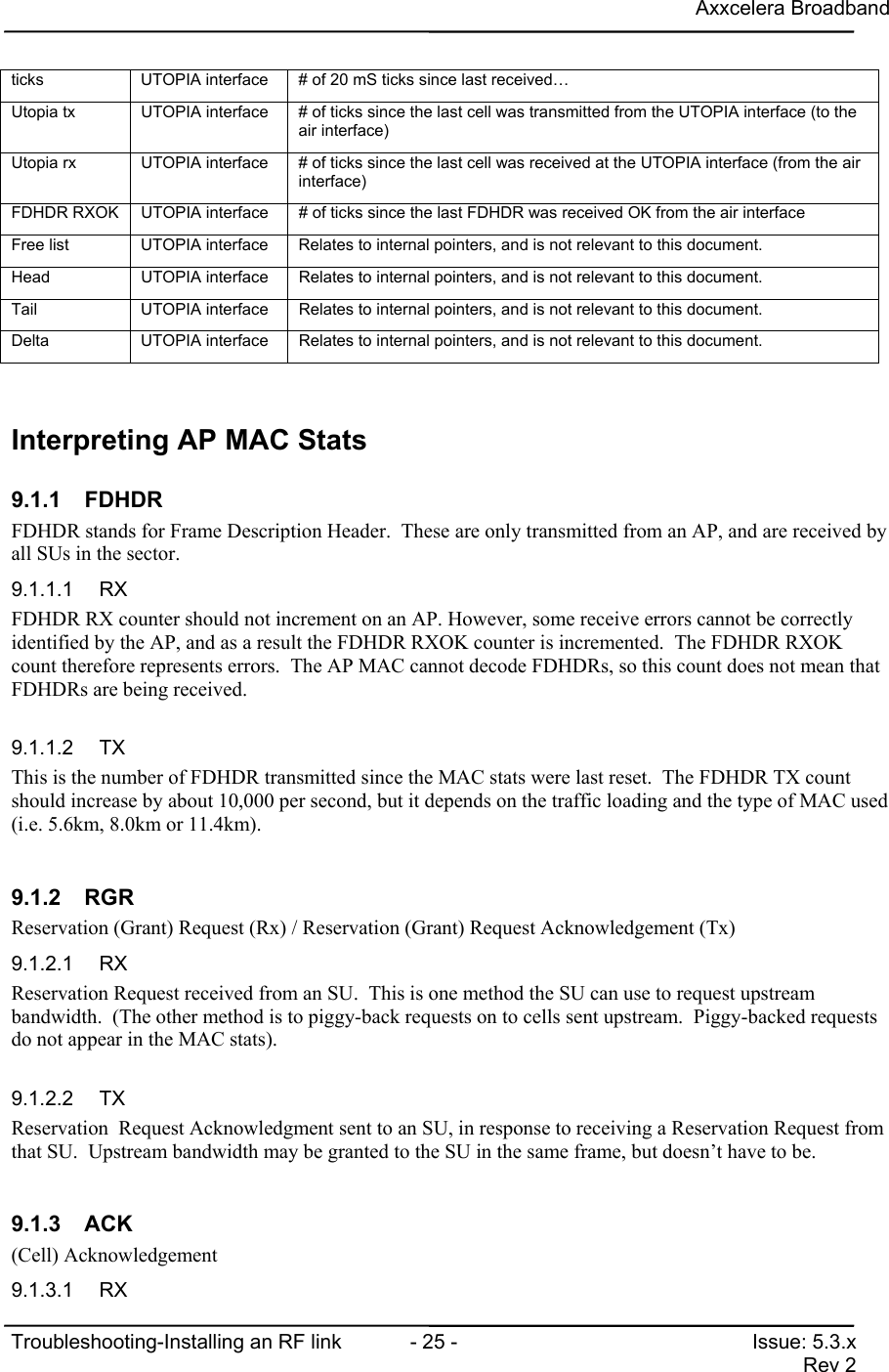
Axxcelera BroadbandTroubleshooting-Installing an RF link  - 25 - Issue: 5.3.xRev 2ticks UTOPIA interface # of 20 mS ticks since last received…Utopia tx UTOPIA interface # of ticks since the last cell was transmitted from the UTOPIA interface (to theair interface)Utopia rx UTOPIA interface # of ticks since the last cell was received at the UTOPIA interface (from the airinterface)FDHDR RXOK UTOPIA interface # of ticks since the last FDHDR was received OK from the air interfaceFree list UTOPIA interface Relates to internal pointers, and is not relevant to this document.Head UTOPIA interface Relates to internal pointers, and is not relevant to this document.Tail UTOPIA interface Relates to internal pointers, and is not relevant to this document.Delta UTOPIA interface Relates to internal pointers, and is not relevant to this document.Interpreting AP MAC Stats9.1.1 FDHDRFDHDR stands for Frame Description Header.  These are only transmitted from an AP, and are received byall SUs in the sector.   9.1.1.1 RXFDHDR RX counter should not increment on an AP. However, some receive errors cannot be correctlyidentified by the AP, and as a result the FDHDR RXOK counter is incremented.  The FDHDR RXOKcount therefore represents errors.  The AP MAC cannot decode FDHDRs, so this count does not mean thatFDHDRs are being received.9.1.1.2 TXThis is the number of FDHDR transmitted since the MAC stats were last reset.  The FDHDR TX countshould increase by about 10,000 per second, but it depends on the traffic loading and the type of MAC used(i.e. 5.6km, 8.0km or 11.4km).9.1.2 RGRReservation (Grant) Request (Rx) / Reservation (Grant) Request Acknowledgement (Tx)9.1.2.1 RXReservation Request received from an SU.  This is one method the SU can use to request upstreambandwidth.  (The other method is to piggy-back requests on to cells sent upstream.  Piggy-backed requestsdo not appear in the MAC stats).9.1.2.2 TXReservation  Request Acknowledgment sent to an SU, in response to receiving a Reservation Request fromthat SU.  Upstream bandwidth may be granted to the SU in the same frame, but doesn’t have to be.9.1.3 ACK(Cell) Acknowledgement9.1.3.1 RX
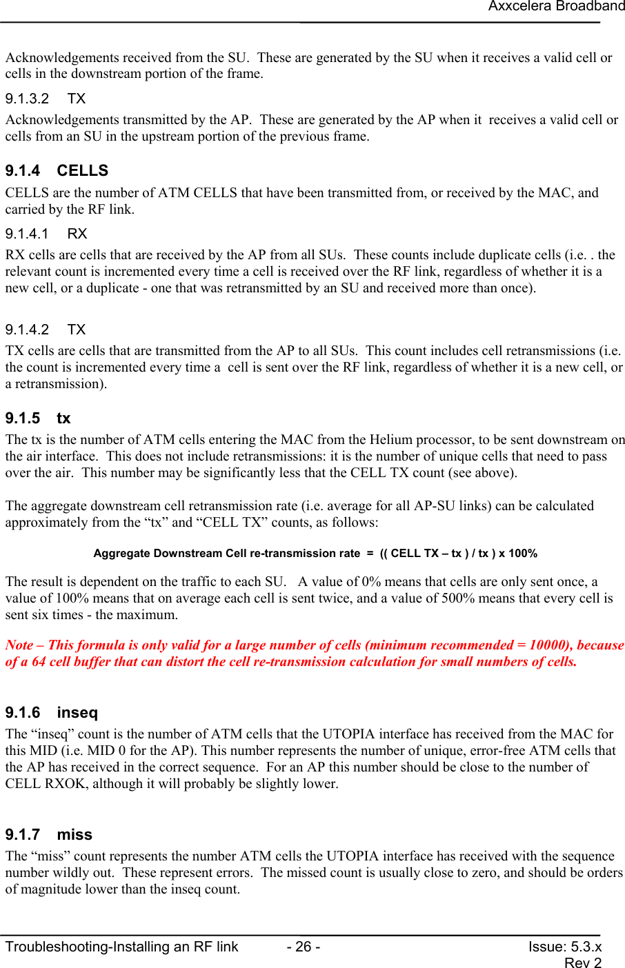
Axxcelera BroadbandTroubleshooting-Installing an RF link  - 26 - Issue: 5.3.xRev 2Acknowledgements received from the SU.  These are generated by the SU when it receives a valid cell orcells in the downstream portion of the frame.9.1.3.2 TXAcknowledgements transmitted by the AP.  These are generated by the AP when it  receives a valid cell orcells from an SU in the upstream portion of the previous frame.9.1.4 CELLSCELLS are the number of ATM CELLS that have been transmitted from, or received by the MAC, andcarried by the RF link.9.1.4.1 RXRX cells are cells that are received by the AP from all SUs.  These counts include duplicate cells (i.e. . therelevant count is incremented every time a cell is received over the RF link, regardless of whether it is anew cell, or a duplicate - one that was retransmitted by an SU and received more than once).9.1.4.2 TXTX cells are cells that are transmitted from the AP to all SUs.  This count includes cell retransmissions (i.e.the count is incremented every time a  cell is sent over the RF link, regardless of whether it is a new cell, ora retransmission).9.1.5 txThe tx is the number of ATM cells entering the MAC from the Helium processor, to be sent downstream onthe air interface.  This does not include retransmissions: it is the number of unique cells that need to passover the air.  This number may be significantly less that the CELL TX count (see above).The aggregate downstream cell retransmission rate (i.e. average for all AP-SU links) can be calculatedapproximately from the “tx” and “CELL TX” counts, as follows:Aggregate Downstream Cell re-transmission rate  =  (( CELL TX – tx ) / tx ) x 100%The result is dependent on the traffic to each SU.   A value of 0% means that cells are only sent once, avalue of 100% means that on average each cell is sent twice, and a value of 500% means that every cell issent six times - the maximum.Note – This formula is only valid for a large number of cells (minimum recommended = 10000), becauseof a 64 cell buffer that can distort the cell re-transmission calculation for small numbers of cells.9.1.6 inseqThe “inseq” count is the number of ATM cells that the UTOPIA interface has received from the MAC forthis MID (i.e. MID 0 for the AP). This number represents the number of unique, error-free ATM cells thatthe AP has received in the correct sequence.  For an AP this number should be close to the number ofCELL RXOK, although it will probably be slightly lower.9.1.7 missThe “miss” count represents the number ATM cells the UTOPIA interface has received with the sequencenumber wildly out.  These represent errors.  The missed count is usually close to zero, and should be ordersof magnitude lower than the inseq count.
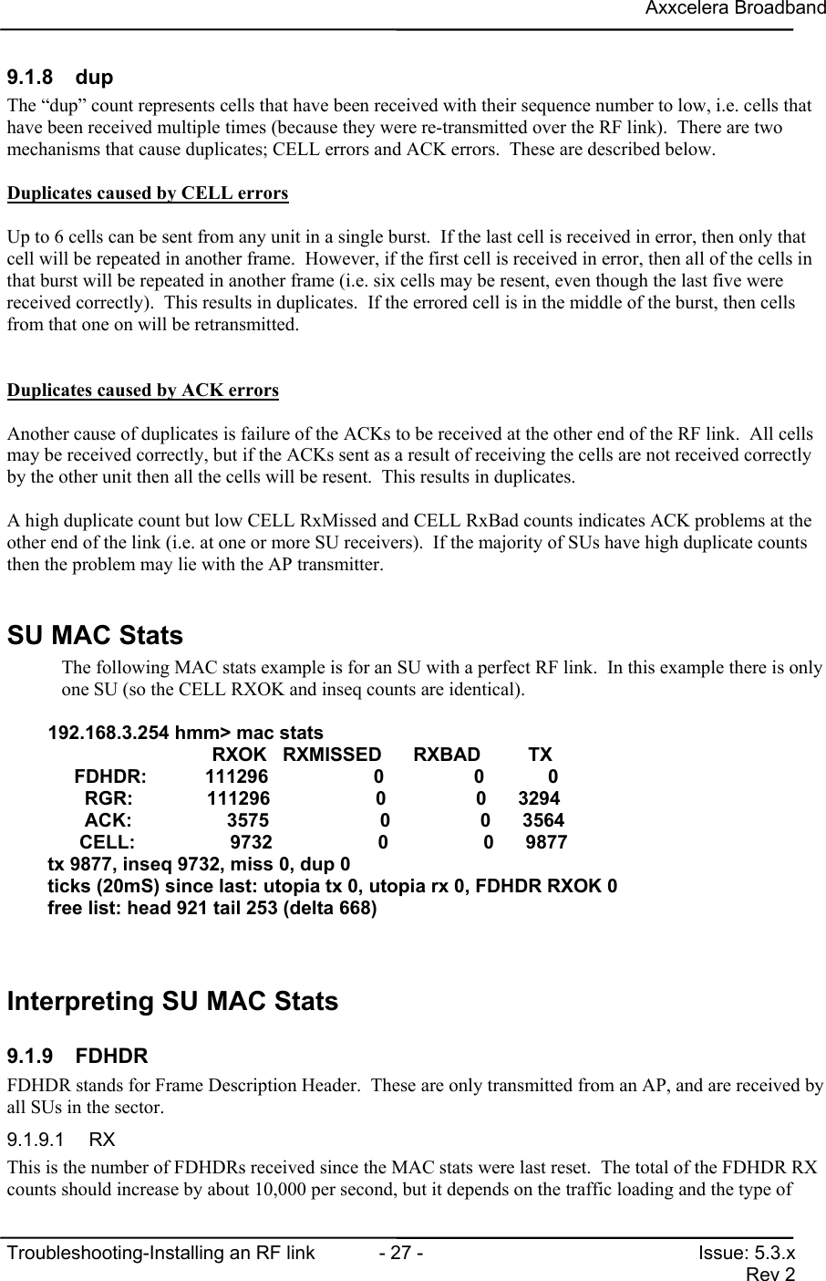
Axxcelera BroadbandTroubleshooting-Installing an RF link  - 27 - Issue: 5.3.xRev 29.1.8 dupThe “dup” count represents cells that have been received with their sequence number to low, i.e. cells thathave been received multiple times (because they were re-transmitted over the RF link).  There are twomechanisms that cause duplicates; CELL errors and ACK errors.  These are described below.Duplicates caused by CELL errorsUp to 6 cells can be sent from any unit in a single burst.  If the last cell is received in error, then only thatcell will be repeated in another frame.  However, if the first cell is received in error, then all of the cells inthat burst will be repeated in another frame (i.e. six cells may be resent, even though the last five werereceived correctly).  This results in duplicates.  If the errored cell is in the middle of the burst, then cellsfrom that one on will be retransmitted.Duplicates caused by ACK errorsAnother cause of duplicates is failure of the ACKs to be received at the other end of the RF link.  All cellsmay be received correctly, but if the ACKs sent as a result of receiving the cells are not received correctlyby the other unit then all the cells will be resent.  This results in duplicates.A high duplicate count but low CELL RxMissed and CELL RxBad counts indicates ACK problems at theother end of the link (i.e. at one or more SU receivers).  If the majority of SUs have high duplicate countsthen the problem may lie with the AP transmitter.SU MAC StatsThe following MAC stats example is for an SU with a perfect RF link.  In this example there is onlyone SU (so the CELL RXOK and inseq counts are identical).192.168.3.254 hmm> mac stats                  RXOK   RXMISSED      RXBAD         TX     FDHDR:           111296                    0                 0            0       RGR:              111296                    0                 0      3294       ACK:                  3575                     0                 0      3564      CELL:                  9732                    0                  0      9877tx 9877, inseq 9732, miss 0, dup 0ticks (20mS) since last: utopia tx 0, utopia rx 0, FDHDR RXOK 0free list: head 921 tail 253 (delta 668)Interpreting SU MAC Stats9.1.9 FDHDRFDHDR stands for Frame Description Header.  These are only transmitted from an AP, and are received byall SUs in the sector.9.1.9.1 RXThis is the number of FDHDRs received since the MAC stats were last reset.  The total of the FDHDR RXcounts should increase by about 10,000 per second, but it depends on the traffic loading and the type of
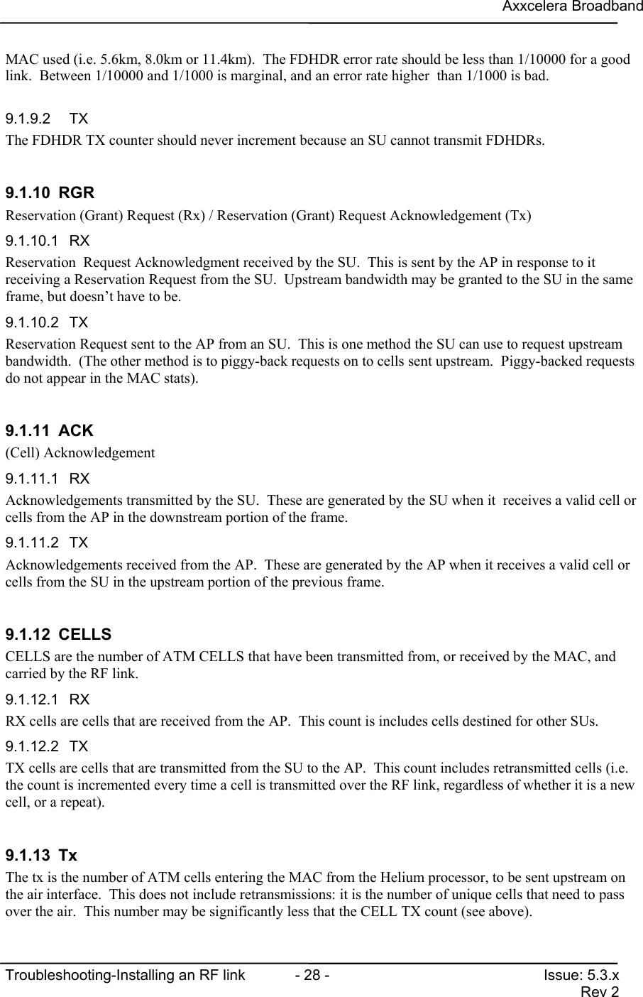
Axxcelera BroadbandTroubleshooting-Installing an RF link  - 28 - Issue: 5.3.xRev 2MAC used (i.e. 5.6km, 8.0km or 11.4km).  The FDHDR error rate should be less than 1/10000 for a goodlink.  Between 1/10000 and 1/1000 is marginal, and an error rate higher  than 1/1000 is bad.9.1.9.2 TXThe FDHDR TX counter should never increment because an SU cannot transmit FDHDRs.9.1.10 RGRReservation (Grant) Request (Rx) / Reservation (Grant) Request Acknowledgement (Tx)9.1.10.1 RXReservation  Request Acknowledgment received by the SU.  This is sent by the AP in response to itreceiving a Reservation Request from the SU.  Upstream bandwidth may be granted to the SU in the sameframe, but doesn’t have to be.9.1.10.2 TXReservation Request sent to the AP from an SU.  This is one method the SU can use to request upstreambandwidth.  (The other method is to piggy-back requests on to cells sent upstream.  Piggy-backed requestsdo not appear in the MAC stats).9.1.11 ACK(Cell) Acknowledgement9.1.11.1 RXAcknowledgements transmitted by the SU.  These are generated by the SU when it  receives a valid cell orcells from the AP in the downstream portion of the frame.9.1.11.2 TXAcknowledgements received from the AP.  These are generated by the AP when it receives a valid cell orcells from the SU in the upstream portion of the previous frame.9.1.12 CELLSCELLS are the number of ATM CELLS that have been transmitted from, or received by the MAC, andcarried by the RF link.9.1.12.1 RXRX cells are cells that are received from the AP.  This count is includes cells destined for other SUs.9.1.12.2 TXTX cells are cells that are transmitted from the SU to the AP.  This count includes retransmitted cells (i.e.the count is incremented every time a cell is transmitted over the RF link, regardless of whether it is a newcell, or a repeat).9.1.13 TxThe tx is the number of ATM cells entering the MAC from the Helium processor, to be sent upstream onthe air interface.  This does not include retransmissions: it is the number of unique cells that need to passover the air.  This number may be significantly less that the CELL TX count (see above).
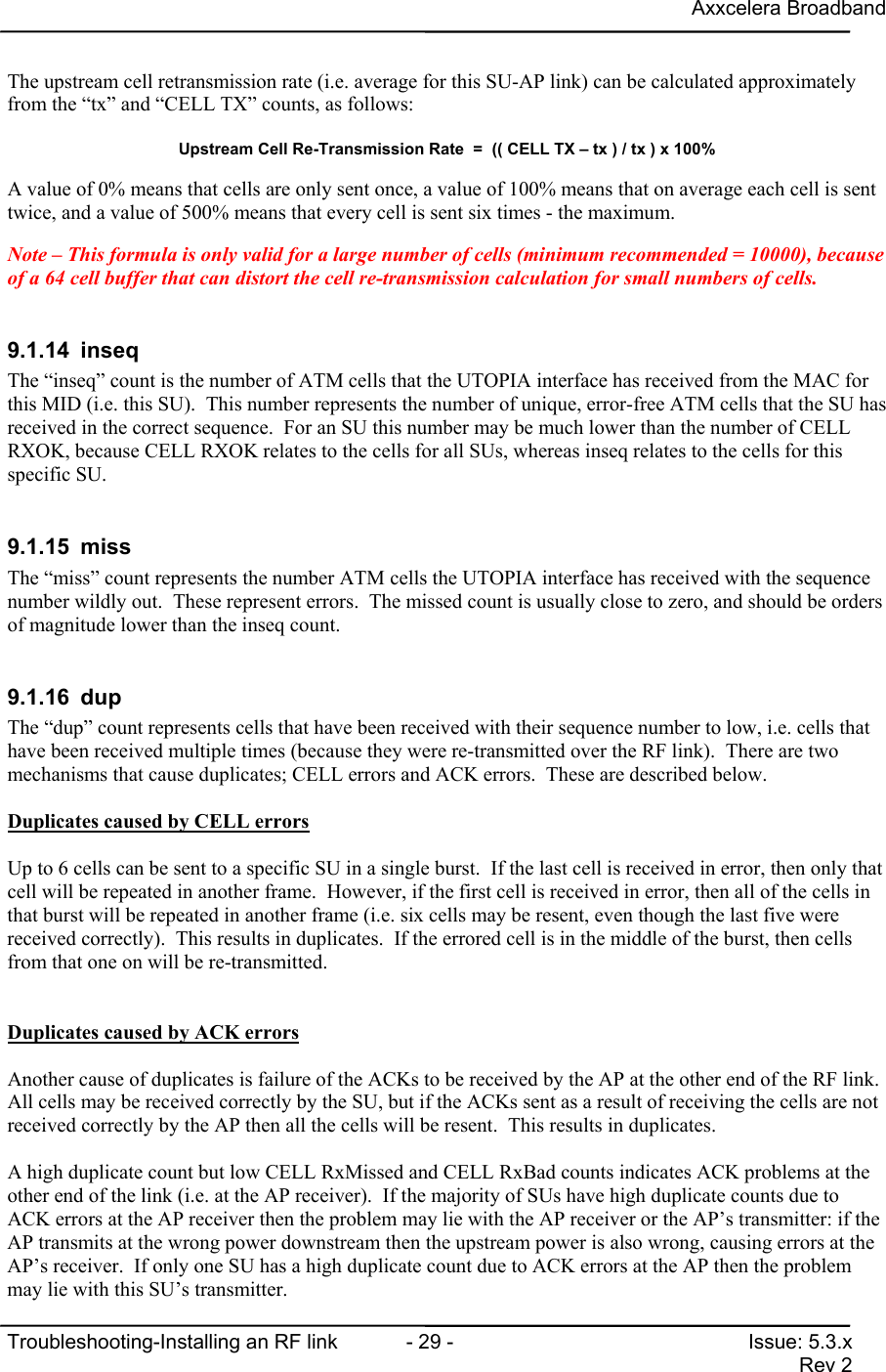
Axxcelera BroadbandTroubleshooting-Installing an RF link  - 29 - Issue: 5.3.xRev 2The upstream cell retransmission rate (i.e. average for this SU-AP link) can be calculated approximatelyfrom the “tx” and “CELL TX” counts, as follows:Upstream Cell Re-Transmission Rate  =  (( CELL TX – tx ) / tx ) x 100%A value of 0% means that cells are only sent once, a value of 100% means that on average each cell is senttwice, and a value of 500% means that every cell is sent six times - the maximum.Note – This formula is only valid for a large number of cells (minimum recommended = 10000), becauseof a 64 cell buffer that can distort the cell re-transmission calculation for small numbers of cells.9.1.14 inseqThe “inseq” count is the number of ATM cells that the UTOPIA interface has received from the MAC forthis MID (i.e. this SU).  This number represents the number of unique, error-free ATM cells that the SU hasreceived in the correct sequence.  For an SU this number may be much lower than the number of CELLRXOK, because CELL RXOK relates to the cells for all SUs, whereas inseq relates to the cells for thisspecific SU.9.1.15 missThe “miss” count represents the number ATM cells the UTOPIA interface has received with the sequencenumber wildly out.  These represent errors.  The missed count is usually close to zero, and should be ordersof magnitude lower than the inseq count.9.1.16 dupThe “dup” count represents cells that have been received with their sequence number to low, i.e. cells thathave been received multiple times (because they were re-transmitted over the RF link).  There are twomechanisms that cause duplicates; CELL errors and ACK errors.  These are described below.Duplicates caused by CELL errorsUp to 6 cells can be sent to a specific SU in a single burst.  If the last cell is received in error, then only thatcell will be repeated in another frame.  However, if the first cell is received in error, then all of the cells inthat burst will be repeated in another frame (i.e. six cells may be resent, even though the last five werereceived correctly).  This results in duplicates.  If the errored cell is in the middle of the burst, then cellsfrom that one on will be re-transmitted.Duplicates caused by ACK errorsAnother cause of duplicates is failure of the ACKs to be received by the AP at the other end of the RF link.All cells may be received correctly by the SU, but if the ACKs sent as a result of receiving the cells are notreceived correctly by the AP then all the cells will be resent.  This results in duplicates.A high duplicate count but low CELL RxMissed and CELL RxBad counts indicates ACK problems at theother end of the link (i.e. at the AP receiver).  If the majority of SUs have high duplicate counts due toACK errors at the AP receiver then the problem may lie with the AP receiver or the AP’s transmitter: if theAP transmits at the wrong power downstream then the upstream power is also wrong, causing errors at theAP’s receiver.  If only one SU has a high duplicate count due to ACK errors at the AP then the problemmay lie with this SU’s transmitter.
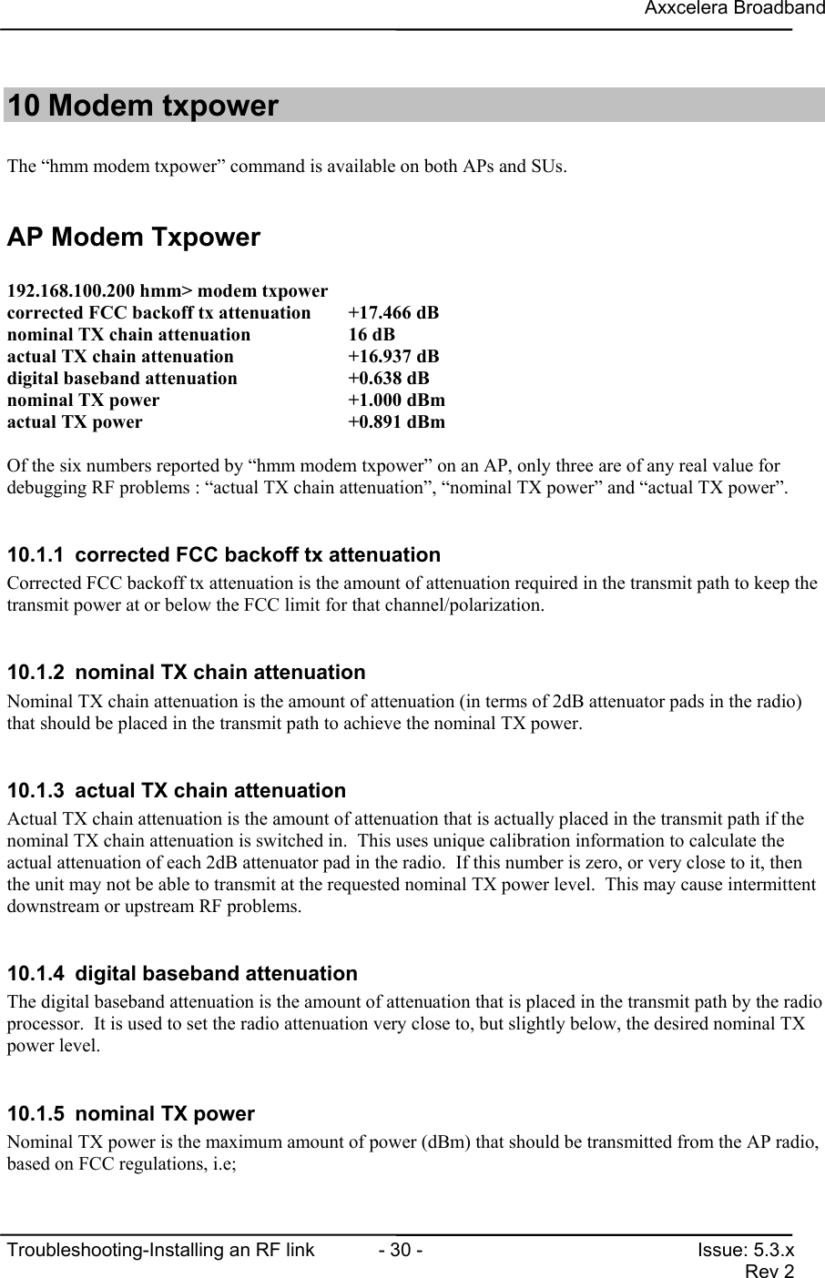
Axxcelera BroadbandTroubleshooting-Installing an RF link  - 30 - Issue: 5.3.xRev 210 Modem txpowerThe “hmm modem txpower” command is available on both APs and SUs.AP Modem Txpower192.168.100.200 hmm> modem txpowercorrected FCC backoff tx attenuation +17.466 dBnominal TX chain attenuation          16 dBactual TX chain attenuation           +16.937 dBdigital baseband attenuation          +0.638 dBnominal TX power                      +1.000 dBmactual TX power                       +0.891 dBmOf the six numbers reported by “hmm modem txpower” on an AP, only three are of any real value fordebugging RF problems : “actual TX chain attenuation”, “nominal TX power” and “actual TX power”.10.1.1  corrected FCC backoff tx attenuationCorrected FCC backoff tx attenuation is the amount of attenuation required in the transmit path to keep thetransmit power at or below the FCC limit for that channel/polarization.10.1.2  nominal TX chain attenuationNominal TX chain attenuation is the amount of attenuation (in terms of 2dB attenuator pads in the radio)that should be placed in the transmit path to achieve the nominal TX power.10.1.3  actual TX chain attenuationActual TX chain attenuation is the amount of attenuation that is actually placed in the transmit path if thenominal TX chain attenuation is switched in.  This uses unique calibration information to calculate theactual attenuation of each 2dB attenuator pad in the radio.  If this number is zero, or very close to it, thenthe unit may not be able to transmit at the requested nominal TX power level.  This may cause intermittentdownstream or upstream RF problems.10.1.4  digital baseband attenuationThe digital baseband attenuation is the amount of attenuation that is placed in the transmit path by the radioprocessor.  It is used to set the radio attenuation very close to, but slightly below, the desired nominal TXpower level.10.1.5  nominal TX powerNominal TX power is the maximum amount of power (dBm) that should be transmitted from the AP radio,based on FCC regulations, i.e;
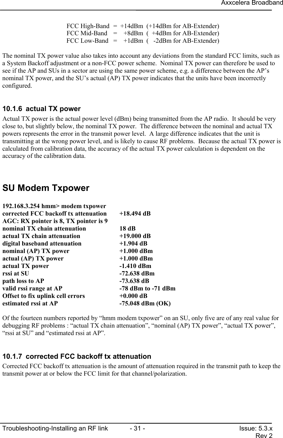
Axxcelera BroadbandTroubleshooting-Installing an RF link  - 31 - Issue: 5.3.xRev 2FCC High-Band =  +14dBm  (+14dBm for AB-Extender)FCC Mid-Band =    +8dBm  (  +4dBm for AB-Extender)FCC Low-Band =    +1dBm  (   -2dBm for AB-Extender)The nominal TX power value also takes into account any deviations from the standard FCC limits, such asa System Backoff adjustment or a non-FCC power scheme.  Nominal TX power can therefore be used tosee if the AP and SUs in a sector are using the same power scheme, e.g. a difference between the AP’snominal TX power, and the SU’s actual (AP) TX power indicates that the units have been incorrectlyconfigured.10.1.6  actual TX powerActual TX power is the actual power level (dBm) being transmitted from the AP radio.  It should be veryclose to, but slightly below, the nominal TX power.  The difference between the nominal and actual TXpowers represents the error in the transmit power level.  A large difference indicates that the unit istransmitting at the wrong power level, and is likely to cause RF problems.  Because the actual TX power iscalculated from calibration data, the accuracy of the actual TX power calculation is dependent on theaccuracy of the calibration data.SU Modem Txpower192.168.3.254 hmm> modem txpowercorrected FCC backoff tx attenuation +18.494 dBAGC: RX pointer is 8, TX pointer is 9nominal TX chain attenuation          18 dBactual TX chain attenuation           +19.000 dBdigital baseband attenuation          +1.904 dBnominal (AP) TX power                 +1.000 dBmactual (AP) TX power                  +1.000 dBmactual TX power                       -1.410 dBmrssi at SU                            -72.638 dBmpath loss to AP                       -73.638 dBvalid rssi range at AP                -78 dBm to -71 dBmOffset to fix uplink cell errors      +0.000 dBestimated rssi at AP                  -75.048 dBm (OK)Of the fourteen numbers reported by “hmm modem txpower” on an SU, only five are of any real value fordebugging RF problems : “actual TX chain attenuation”, “nominal (AP) TX power”, “actual TX power”,“rssi at SU” and “estimated rssi at AP”.10.1.7  corrected FCC backoff tx attenuationCorrected FCC backoff tx attenuation is the amount of attenuation required in the transmit path to keep thetransmit power at or below the FCC limit for that channel/polarization.
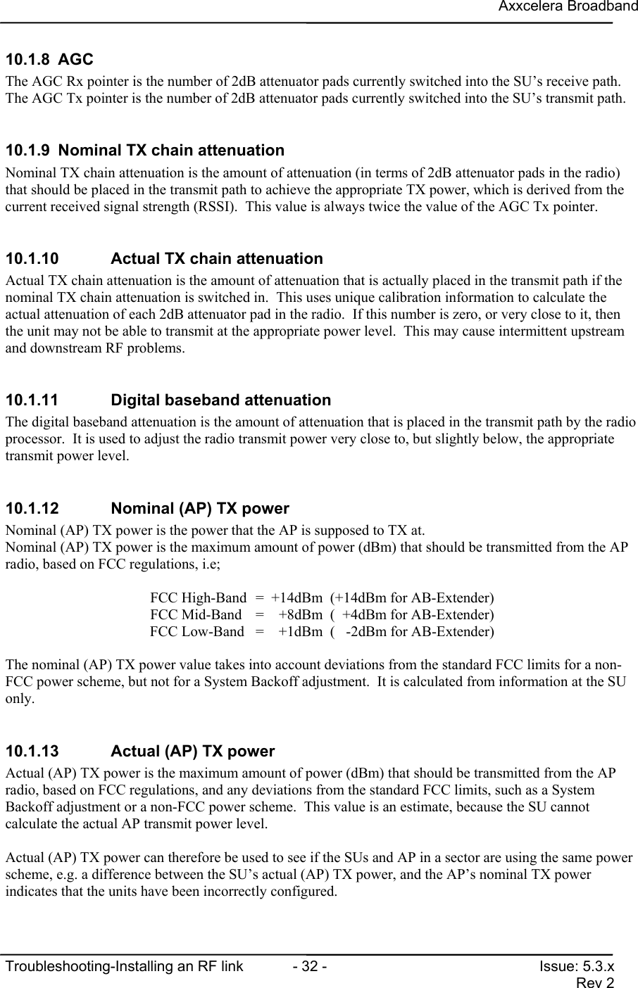
Axxcelera BroadbandTroubleshooting-Installing an RF link  - 32 - Issue: 5.3.xRev 210.1.8 AGCThe AGC Rx pointer is the number of 2dB attenuator pads currently switched into the SU’s receive path.The AGC Tx pointer is the number of 2dB attenuator pads currently switched into the SU’s transmit path.10.1.9  Nominal TX chain attenuationNominal TX chain attenuation is the amount of attenuation (in terms of 2dB attenuator pads in the radio)that should be placed in the transmit path to achieve the appropriate TX power, which is derived from thecurrent received signal strength (RSSI).  This value is always twice the value of the AGC Tx pointer.10.1.10  Actual TX chain attenuationActual TX chain attenuation is the amount of attenuation that is actually placed in the transmit path if thenominal TX chain attenuation is switched in.  This uses unique calibration information to calculate theactual attenuation of each 2dB attenuator pad in the radio.  If this number is zero, or very close to it, thenthe unit may not be able to transmit at the appropriate power level.  This may cause intermittent upstreamand downstream RF problems.10.1.11  Digital baseband attenuationThe digital baseband attenuation is the amount of attenuation that is placed in the transmit path by the radioprocessor.  It is used to adjust the radio transmit power very close to, but slightly below, the appropriatetransmit power level.10.1.12  Nominal (AP) TX powerNominal (AP) TX power is the power that the AP is supposed to TX at.Nominal (AP) TX power is the maximum amount of power (dBm) that should be transmitted from the APradio, based on FCC regulations, i.e;FCC High-Band =  +14dBm  (+14dBm for AB-Extender)FCC Mid-Band =    +8dBm  (  +4dBm for AB-Extender)FCC Low-Band =    +1dBm  (   -2dBm for AB-Extender)The nominal (AP) TX power value takes into account deviations from the standard FCC limits for a non-FCC power scheme, but not for a System Backoff adjustment.  It is calculated from information at the SUonly.10.1.13  Actual (AP) TX powerActual (AP) TX power is the maximum amount of power (dBm) that should be transmitted from the APradio, based on FCC regulations, and any deviations from the standard FCC limits, such as a SystemBackoff adjustment or a non-FCC power scheme.  This value is an estimate, because the SU cannotcalculate the actual AP transmit power level.Actual (AP) TX power can therefore be used to see if the SUs and AP in a sector are using the same powerscheme, e.g. a difference between the SU’s actual (AP) TX power, and the AP’s nominal TX powerindicates that the units have been incorrectly configured.
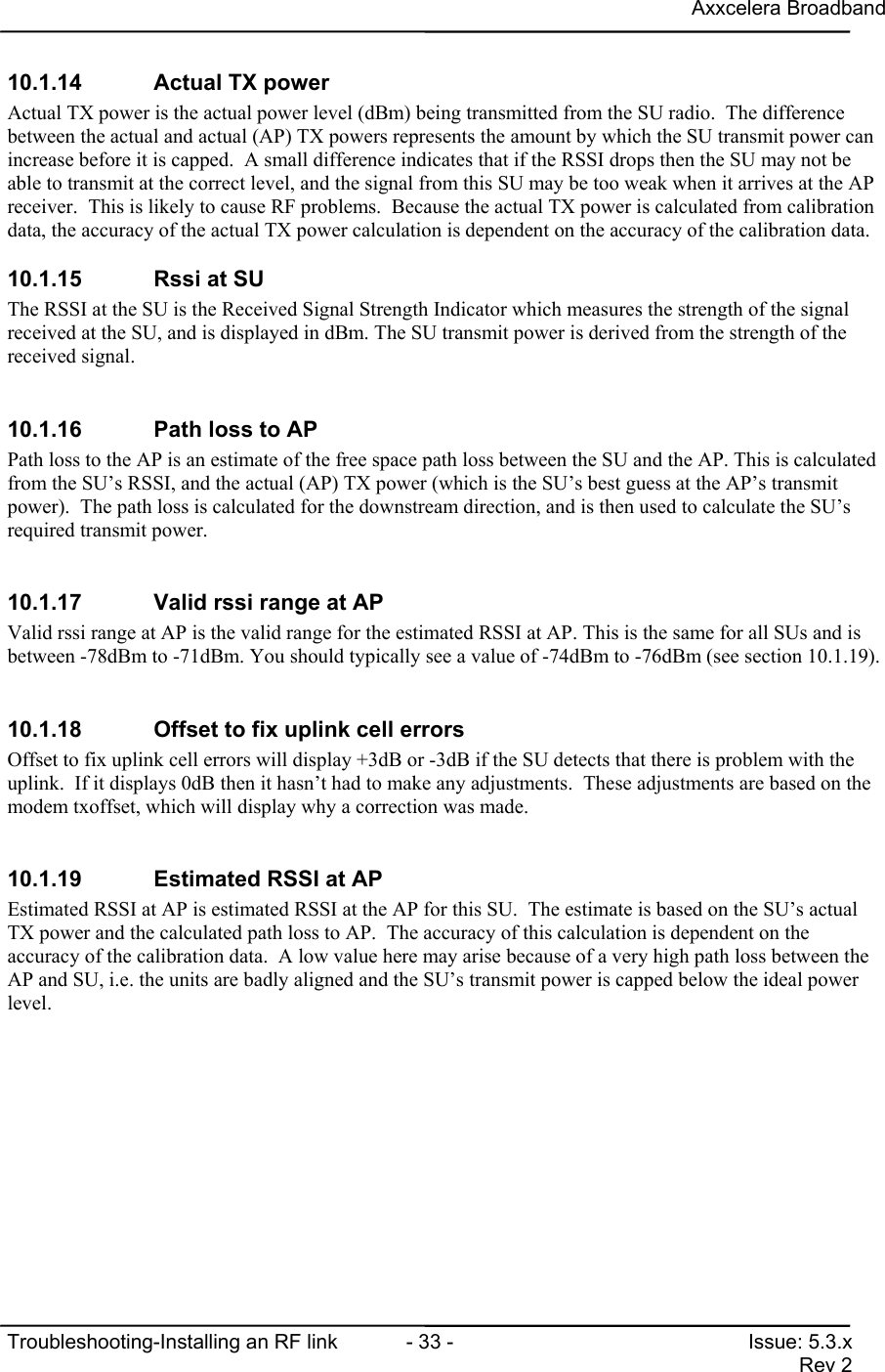
Axxcelera BroadbandTroubleshooting-Installing an RF link  - 33 - Issue: 5.3.xRev 210.1.14  Actual TX powerActual TX power is the actual power level (dBm) being transmitted from the SU radio.  The differencebetween the actual and actual (AP) TX powers represents the amount by which the SU transmit power canincrease before it is capped.  A small difference indicates that if the RSSI drops then the SU may not beable to transmit at the correct level, and the signal from this SU may be too weak when it arrives at the APreceiver.  This is likely to cause RF problems.  Because the actual TX power is calculated from calibrationdata, the accuracy of the actual TX power calculation is dependent on the accuracy of the calibration data.10.1.15  Rssi at SUThe RSSI at the SU is the Received Signal Strength Indicator which measures the strength of the signalreceived at the SU, and is displayed in dBm. The SU transmit power is derived from the strength of thereceived signal.10.1.16  Path loss to APPath loss to the AP is an estimate of the free space path loss between the SU and the AP. This is calculatedfrom the SU’s RSSI, and the actual (AP) TX power (which is the SU’s best guess at the AP’s transmitpower).  The path loss is calculated for the downstream direction, and is then used to calculate the SU’srequired transmit power.10.1.17  Valid rssi range at APValid rssi range at AP is the valid range for the estimated RSSI at AP. This is the same for all SUs and isbetween -78dBm to -71dBm. You should typically see a value of -74dBm to -76dBm (see section 10.1.19).10.1.18  Offset to fix uplink cell errorsOffset to fix uplink cell errors will display +3dB or -3dB if the SU detects that there is problem with theuplink.  If it displays 0dB then it hasn’t had to make any adjustments.  These adjustments are based on themodem txoffset, which will display why a correction was made.10.1.19  Estimated RSSI at APEstimated RSSI at AP is estimated RSSI at the AP for this SU.  The estimate is based on the SU’s actualTX power and the calculated path loss to AP.  The accuracy of this calculation is dependent on theaccuracy of the calibration data.  A low value here may arise because of a very high path loss between theAP and SU, i.e. the units are badly aligned and the SU’s transmit power is capped below the ideal powerlevel.
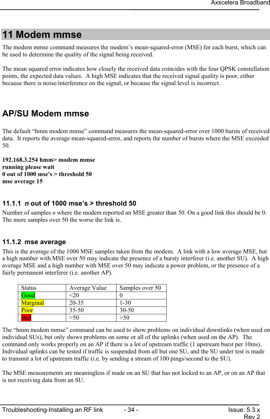
Axxcelera BroadbandTroubleshooting-Installing an RF link  - 34 - Issue: 5.3.xRev 211 Modem mmseThe modem mmse command measures the modem’s mean-squared-error (MSE) for each burst, which canbe used to determine the quality of the signal being received.The mean squared error indicates how closely the received data coincides with the four QPSK constellationpoints, the expected data values.  A high MSE indicates that the received signal quality is poor, eitherbecause there is noise/interference on the signal, or because the signal level is incorrect.AP/SU Modem mmseThe default “hmm modem mmse” command measures the mean-squared-error over 1000 bursts of receiveddata.  It reports the average mean-squared-error, and reports the number of bursts where the MSE exceeded50.192.168.3.254 hmm> modem mmserunning please wait0 out of 1000 mse's > threshold 50mse average 1511.1.1  n out of 1000 mse’s > threshold 50Number of samples n where the modem reported an MSE greater than 50. On a good link this should be 0.The more samples over 50 the worse the link is.11.1.2 mse averageThis is the average of the 1000 MSE samples taken from the modem.  A link with a low average MSE, buta high number with MSE over 50 may indicate the presence of a bursty interferer (i.e. another SU).  A highaverage MSE and a high number with MSE over 50 may indicate a power problem, or the presence of afairly permanent interferer (i.e. another AP).The “hmm modem mmse” command can be used to show problems on individual downlinks (when used onindividual SUs), but only shows problems on some or all of the uplinks (when used on the AP).  Thecommand only works properly on an AP if there is a lot of upstream traffic (1 upstream burst per 10ms).Individual uplinks can be tested if traffic is suspended from all but one SU, and the SU under test is madeto transmit a lot of upstream traffic (i.e. by sending a stream of 100 pings/second to the SU).The MSE measurements are meaningless if made on an SU that has not locked to an AP, or on an AP thatis not receiving data from an SU.Status Average Value Samples over 50Good <20 0Marginal 20-35 1-30Poor 35-50 30-50Bad >50 >50
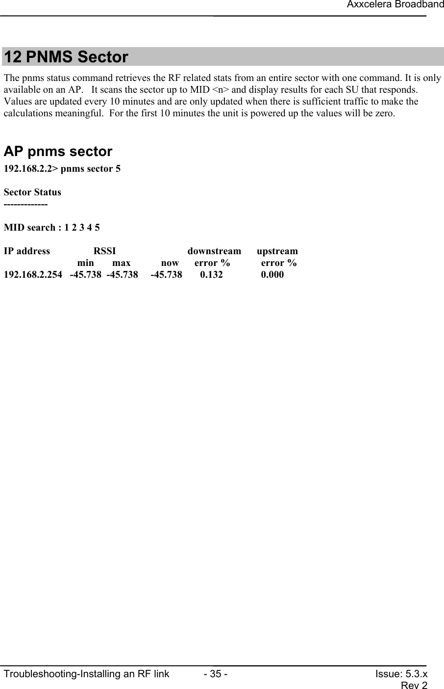
Axxcelera BroadbandTroubleshooting-Installing an RF link  - 35 - Issue: 5.3.xRev 212 PNMS SectorThe pnms status command retrieves the RF related stats from an entire sector with one command. It is onlyavailable on an AP.   It scans the sector up to MID <n> and display results for each SU that responds.Values are updated every 10 minutes and are only updated when there is sufficient traffic to make thecalculations meaningful.  For the first 10 minutes the unit is powered up the values will be zero.AP pnms sector192.168.2.2> pnms sector 5Sector Status-------------MID search : 1 2 3 4 5IP address                 RSSI             downstream      upstream                   min       max           now      error %            error %192.168.2.254   -45.738  -45.738   -45.738       0.132     0.000
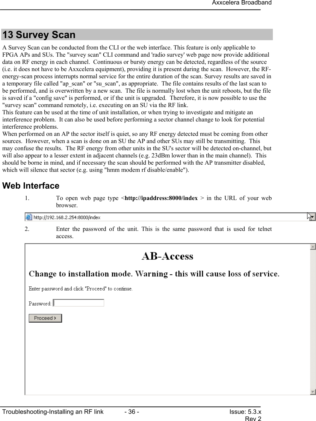
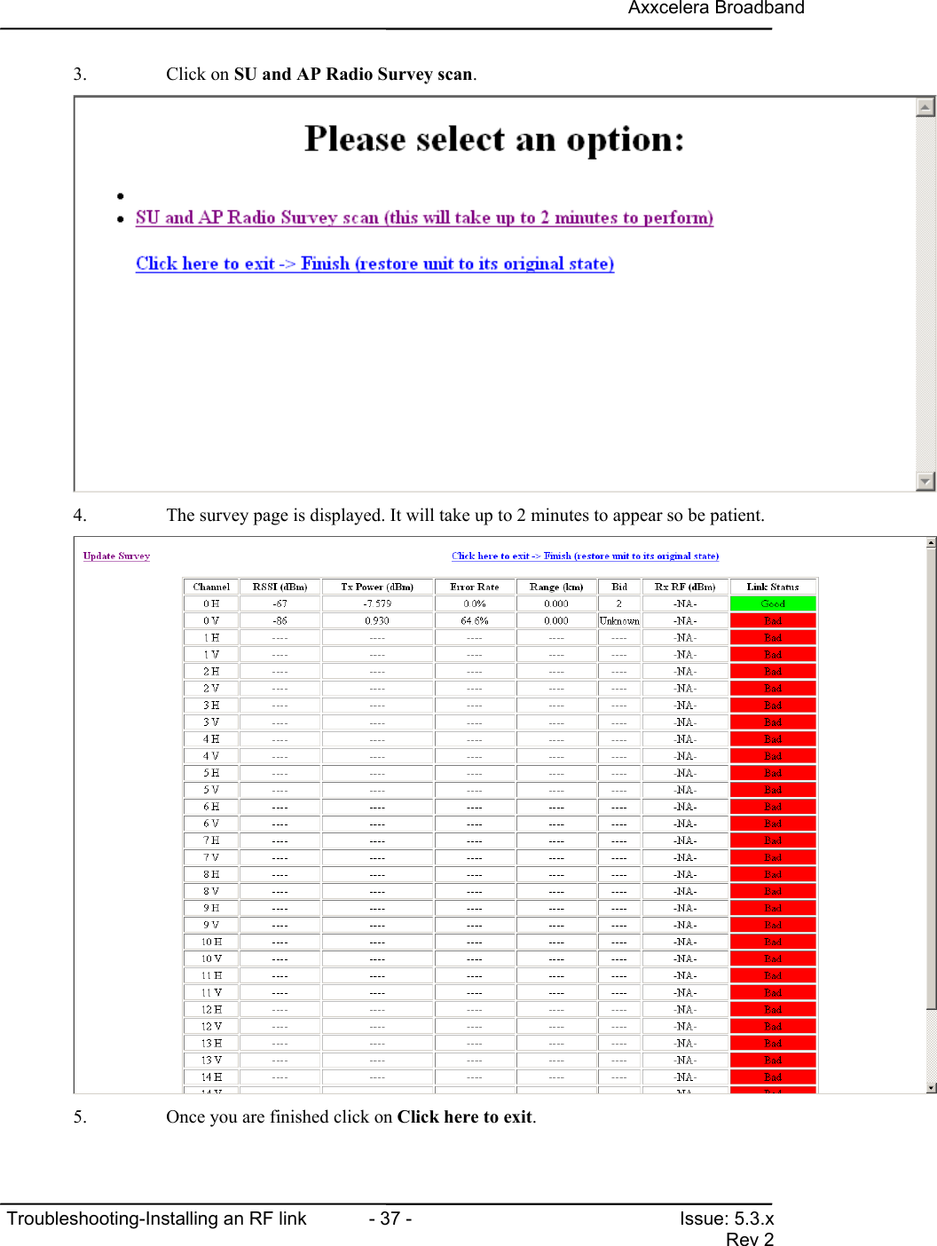
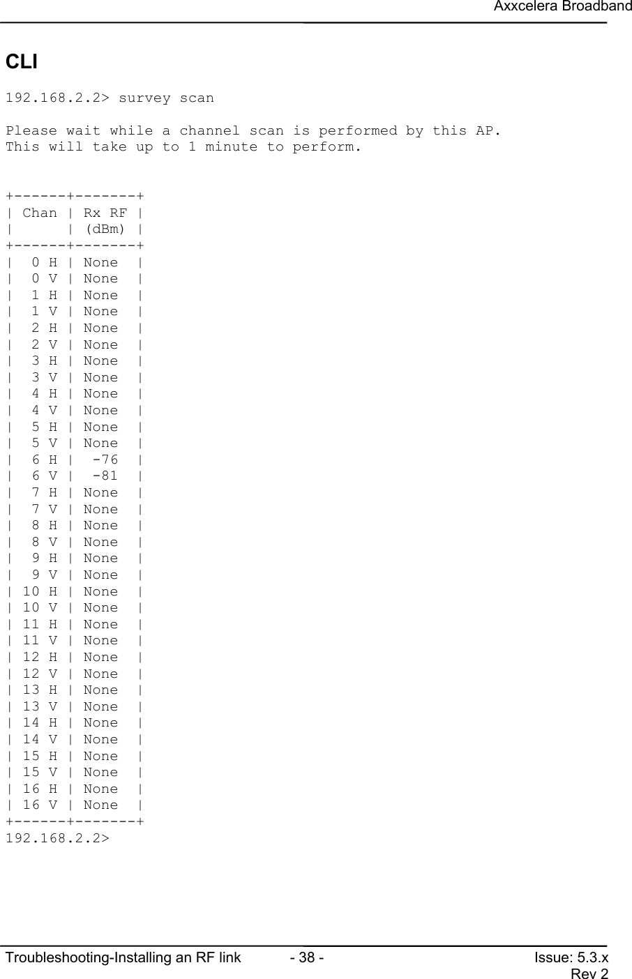
Axxcelera BroadbandTroubleshooting-Installing an RF link  - 36 - Issue: 5.3.xRev 213 Survey ScanA Survey Scan can be conducted from the CLI or the web interface. This feature is only applicable toFPGA APs and SUs. The "survey scan" CLI command and 'radio survey' web page now provide additionaldata on RF energy in each channel.  Continuous or bursty energy can be detected, regardless of the source(i.e. it does not have to be Axxcelera equipment), providing it is present during the scan.  However, the RF-energy-scan process interrupts normal service for the entire duration of the scan. Survey results are saved ina temporary file called "ap_scan" or "su_scan", as appropriate.  The file contains results of the last scan tobe performed, and is overwritten by a new scan.  The file is normally lost when the unit reboots, but the fileis saved if a "config save" is performed, or if the unit is upgraded.  Therefore, it is now possible to use the"survey scan" command remotely, i.e. executing on an SU via the RF link.This feature can be used at the time of unit installation, or when trying to investigate and mitigate aninterference problem.  It can also be used before performing a sector channel change to look for potentialinterference problems.When performed on an AP the sector itself is quiet, so any RF energy detected must be coming from othersources.  However, when a scan is done on an SU the AP and other SUs may still be transmitting.  Thismay confuse the results.  The RF energy from other units in the SU's sector will be detected on-channel, butwill also appear to a lesser extent in adjacent channels (e.g. 23dBm lower than in the main channel).  Thisshould be borne in mind, and if necessary the scan should be performed with the AP transmitter disabled,which will silence that sector (e.g. using "hmm modem rf disable/enable").Web Interface1. To open web page type <http://ipaddress:8000/index > in the URL of your webbrowser.2. Enter the password of the unit. This is the same password that is used for telnetaccess.
Axxcelera BroadbandTroubleshooting-Installing an RF link  - 37 - Issue: 5.3.xRev 23. Click on SU and AP Radio Survey scan.4. The survey page is displayed. It will take up to 2 minutes to appear so be patient.5. Once you are finished click on Click here to exit.
Axxcelera BroadbandTroubleshooting-Installing an RF link  - 38 - Issue: 5.3.xRev 2CLI192.168.2.2> survey scanPlease wait while a channel scan is performed by this AP.This will take up to 1 minute to perform.+------+-------+| Chan | Rx RF ||      | (dBm) |+------+-------+|  0 H | None  ||  0 V | None  ||  1 H | None  ||  1 V | None  ||  2 H | None  ||  2 V | None  ||  3 H | None  ||  3 V | None  ||  4 H | None  ||  4 V | None  ||  5 H | None  ||  5 V | None  ||  6 H |  -76  ||  6 V |  -81  ||  7 H | None  ||  7 V | None  ||  8 H | None  ||  8 V | None  ||  9 H | None  ||  9 V | None  || 10 H | None  || 10 V | None  || 11 H | None  || 11 V | None  || 12 H | None  || 12 V | None  || 13 H | None  || 13 V | None  || 14 H | None  || 14 V | None  || 15 H | None  || 15 V | None  || 16 H | None  || 16 V | None  |+------+-------+192.168.2.2>
Axxcelera BroadbandTroubleshooting-Installing an RF link  - 39 - Issue: 5.3.xRev 214 Modem msreg 6 1The modem msreg 6 1 command will display the RX digital AGC level.  This is a fine gain adjustment.  Itis the only dynamic gain adjustment on APs.  SUs also have a course gain adjustment, the Radio AGC,which adjusts the gain over a wide range.On SUs the Rx digital AGC does not assist in debugging, because of the presence of the Radio AGC.However, for APs it indicates if the received signal is too strong or too weak.AP Modem msreg 6 1The signal from all SUs should be about –74dBm on arrival at the AP receiver.If the signal is too strong then the gain of the digital AGC drops.  If the signal is too weak then the gain ofthe digital AGC increases.  The digital AGC is fast-acting and is reset at the end of each burst to its startingpoint of maximum gain (corresponding to a register value of 127).  As the signal is received, the gain of thedigital AGC drops whenever the signal level is above the correct level.When the received signal level is about –74dBm the digital AGC drops from 127 to an average range of 30-50.  If the signal level is too strong the digital AGC may drop to its lowest gain (corresponding to a registervalue of 21).  Readings of 21 indicate that the receiver is overloaded.  If the signal level is too weak thenthe digital AGC will not drop as far as expected, and it may even remain at its starting position of 127.192.168.100.200 hmm> modem msreg 6 1001: [0x06] 0x33 51Average : 51.0Status Average valueBad 21Marginal 22-25Good 25-55Marginal 55-70Bad >70Values for the Rx digital AGC can range from 21 to 127, and should be 25-55 for typical AP receiver.The command only works properly on an AP if there is upstream traffic (one burst per reading of msreg 6).Individual uplinks can be tested if traffic is suspended from all but one SU, and the SU under test is madeto transmit upstream traffic (i.e. by sending a stream of pings/second to the SU).The digital AGC measurements are meaningless if the AP is not receiving data from an SU.
Axxcelera BroadbandTroubleshooting-Installing an RF link  - 40 - Issue: 5.3.xRev 215 Modem rxdc statsThe “hmm modem rxdc stats” command can help to spot intermittent problems with radio links.  It displaysthe number of times the receiver dc offsets were recalibrated, and for what reason, e.g.AP/SU modem rxdc stats192.168.100.200 hmm> modem rxdc statsTRIGGER         : TEMPERATURE    FDHDR ERROR    CELL ERROR     ACK ERRORFREQUENCY    : 1                        0                             0                 0OFFSET         : MIN            MAXI                       : 0                  0Q                     : 3                  4The stats can be reset to zero with the “hmm modem rxdc stats z” command.Recalibrations are required when the temperature changes, and may occasionally be triggered by errorswhen the offesets change without a temperature change.  However, because the recalibrations are triggeredby a high error rate in any one second interval, the rxdc stats tend to show intermittent radio problems thatmay not be obvious from the MAC stats (because the average error rate may be low).  As a rule of thumb,error-triggers should be less than temperature-triggers.  If the number of error-triggers are more than tentimes the number of temperature-triggers then there is a definite problem with the received signal.  Wherean AP has a poor signal at its receiver (due to interference or a power-control issue, for example) then theerror-triggers are typically one hundred times the number of temperature-triggers.  Once a calibration istriggered by errors there is a 1 minute delay before it can be triggered again.  Therefore, as an example, aunit with an uptime of 10 hours (i.e. 600 minutes) and a total of 600 error-triggered rx dc offset calibrationsmeans that high error rate was always present.The “hmm modem mmse” and “hmm modem msreg 6” commands can be used to confirm a problem, anddiagnose a possible cause.
Axxcelera BroadbandTroubleshooting-Installing an RF link  - 41 - Issue: 5.3.xRev 216 Bun list channelsBun list channels can be used to determine which PVC (SU) traffic is coming from. This command issomewhat obsolete with the introduction of the “pnms sector” command in the 5.2.x and later releases.192.168.100.200> bun list channelsPort atm25i  0:  Enabled:  true   TxPkts: 0           RxPkts:     0/0      TxVPI/VCI:   0/0      RxVPI/VCI:   0/0  1:  Enabled:  true   TxPkts: 0           RxPkts:     0/0      TxVPI/VCI:   0/0      RxVPI/VCI:   0/0  2:  Enabled:  true   TxPkts: 0           RxPkts:     0/0      TxVPI/VCI:   0/0      RxVPI/VCI:   0/3  3:  Enabled:  true   TxPkts: 0           RxPkts:     0/0      TxVPI/VCI:   0/0      RxVPI/VCI:   0/4Port atm25m  0:  Enabled:  true   TxPkts: 0           RxPkts:     0/0      TxVPI/VCI:   0/0      RxVPI/VCI:   0/0  1:  Enabled:  true   TxPkts: 0           RxPkts:     0/0      TxVPI/VCI:   0/0      RxVPI/VCI:   0/0  2:  Enabled:  true   TxPkts: 0           RxPkts:     0/0      TxVPI/VCI:   0/0      RxVPI/VCI:   0/3  3:  Enabled:  true   TxPkts: 0           RxPkts:     0/0      TxVPI/VCI:   0/0      RxVPI/VCI:   0/4  4:  Enabled:  true   TxPkts: 127       RxPkts:   168/10    TxVPI/VCI:   0/768  RxVPI/VCI:   0/768Port ciao does not support channel accessPort Ethernet  0:  Enabled:  true   TxPkts: 723         RxPkts:   793/016.1.1 RxPkts:The receive packets will tell you if a link is having problems. There are 2 numbers for the received packets,the first is for the total number (168), the second is for packets received with an error(10). If the secondnumber is large compared to the first number this would indicate a problem. You don’t really care what theexact numbers are, because you are only using this to identify a possible problem.

Navigation menu