AxyomCore LTE4001-41 Apex Strand Small Cell (B41) User Manual PICO CELL Hardware Installation Gd
Casa Systems, Inc. Apex Strand Small Cell (B41) PICO CELL Hardware Installation Gd
UserManual.wiki
>
AxyomCore
>
LTE4001 41 User Manual
Users Manual
Navigation menu
Upload a User Manual
Namespaces
Wiki Guide
HTML
PDF
Info
Views
User Manual
Discussion / Help
Navigation
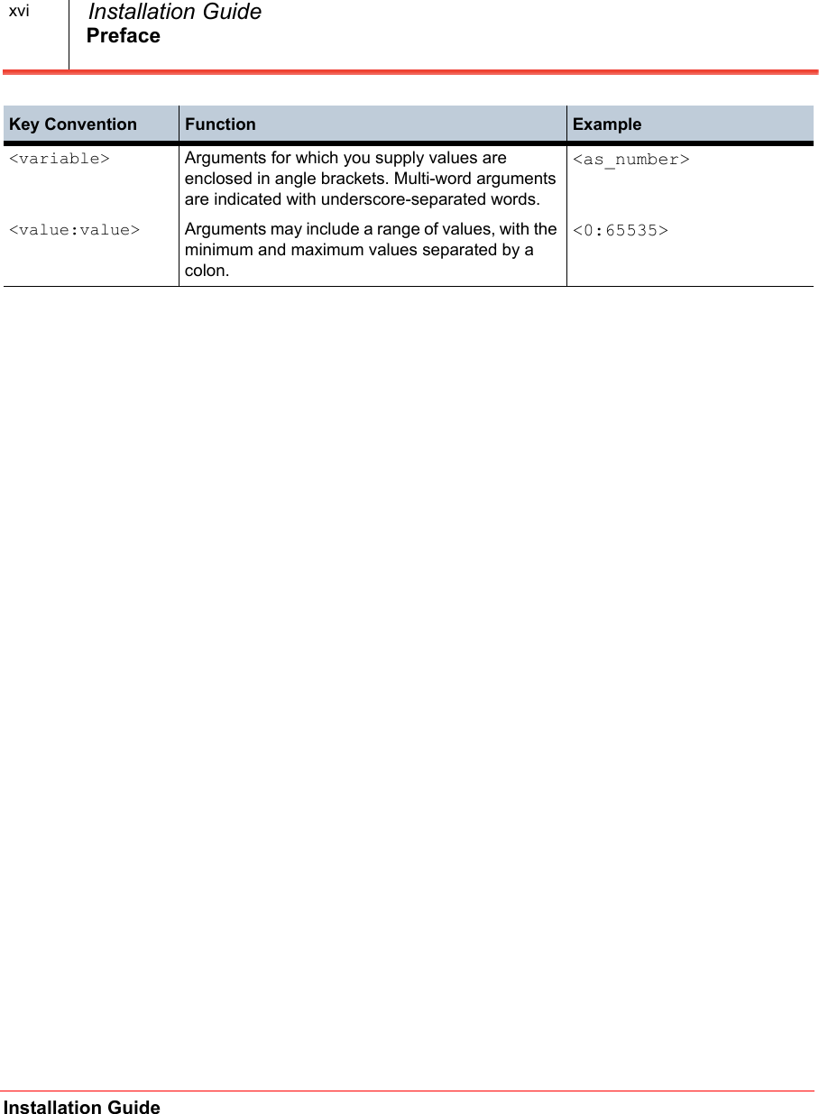
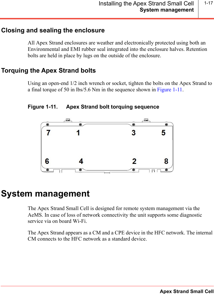
![PrefaceApex Strand Small CellInstallation Guide xvRevision history• 01.00.00 — July 2018• 01.02.00 — September 2018• 01.03.00 — October 2018• 01.04.00 — December 2018Supported software releasesThe following Casa software release(s) are supported in this latest revision:• 4.2.0 — August 2018• 4.2.1 — September 2018• 4.2.2 — October 2018• 4.2.3 — December 2018Conventions used in Casa documentationKey Convention Function Exampleboldface font Commands and keywords are in boldface. Enter abcItalic font Emphasized terminology is in italics. burst profilebrackets [ ] Elements in square brackets are optional. [<ip_addr>]braces {x | y | z} Indicates a required argument with a choice of values; choose one.{enabled | disabled}brackets [x | y | z] Indicates an optional argument with a choice of values; choose one.[abc | 123]vertical bar | Separates parameter values. Same as “or.” {TCP | TLS}string A non-quoted set of characters. Do not use quotation marks (“”) around the string as the string will include the quotation marks.abcscreen font CLI sessions and information the system displays are in screen font. CASA(config)#boldface screen fontInformation you must enter is in boldface screen font.](https://usermanual.wiki/AxyomCore/LTE4001-41/User-Guide-4106733-Page-15.png)