AxyomCore LTE4001-41 Apex Strand Small Cell (B41) User Manual PICO CELL Hardware Installation Gd
Casa Systems, Inc. Apex Strand Small Cell (B41) PICO CELL Hardware Installation Gd
Users Manual

DOC-3077-01
Document Revision 1.04.00
December 2018
Apex Strand Small Cell
Installation Guide
Version 4.2.3

© 2018 Casa Systems, Inc.
All rights reserved. Licensed software products are owned by Casa Systems or its suppliers and are protected
by United States copyright laws and international treaty provisions.
The information regarding the product in this manual is subject to change without notice. All statements,
information, and recommendations in this manual are believed to be accurate but are presented without
warranty of any kind, express of implied. Users must take full responsibility for their application of the product.
In no event shall Casa or its suppliers be liable for any indirect, special, consequential, or incidental damages,
including, without limitation, lost profits or loss or damage to data arising out of the use or inability to use this
manual, even if Casa or its suppliers have been advised of the possibility of such damages.

Apex Strand Small Cell
iii
Contents
Preface
About this guide ..................................................................................................... v
Safety information and symbols............................................................................ vi
Safety and Regulatory Agency Compliance .....................................................iii-vii.
Product safety information ..............................................................................iii-viii.
Symbols ....................................................................................................iii-viii.
Contacting Casa ................................................................................................. xiv
Corporate facility ........................................................................................... xiv
Technical documentation .............................................................................. xiv
Revision history.............................................................................................. xv
Supported software releases ......................................................................... xv
Conventions used in Casa documentation .......................................................... xv
Acronyms ......................................................................................................xvii
Chapter 1. Installing the Apex Strand Small Cell
Safety guidelines ............................................................................................... 1-2.
Required tools ................................................................................................... 1-3.
Required installation components ..................................................................... 1-3.
Approved antenna(s) ........................................................................................ 1-3.
Components of the Apex Strand Small Cell ...................................................... 1-4.
Field Replacement Units ............................................................................. 1-5.
Non-Field Replaceable Units ...................................................................... 1-5.
Power inputs ..................................................................................................... 1-6.
RF/AC input connector ................................................................................ 1-6.
Alarm Connector ......................................................................................... 1-7.
Status LEDs ................................................................................................ 1-7.

Contents
Installation Guide
Installation Guide
iv
Fuse location ..................................................................................................... 1-8.
Network connections ......................................................................................... 1-9.
Unpacking the system ..................................................................................... 1-10.
Installing the Apex Strand ................................................................................1-11.
Installation prerequisites ............................................................................1-11.
Powering the Apex Strand ........................................................................ 1-12.
Apex Strand Kill Switch ............................................................................. 1-13.
Selecting the installation location .............................................................. 1-14.
Hanging the Apex Strand .......................................................................... 1-15.
RF provisioning ......................................................................................... 1-16.
Connect the power source ........................................................................ 1-16.
Verify the Strand Operation ....................................................................... 1-16.
Closing and sealing the enclosure ............................................................ 1-17.
Torquing the Apex Strand bolts ................................................................. 1-17.
System management ...................................................................................... 1-17.
Apex Strand Small Cell
v
Preface
About this guide
The Casa Systems – Apex Strand Small Cell Installation Guide covers the initial
hardware and software installation for the Casa Apex Strand Small Cell. This guide is
intended for system administrators, engineers, and operators who are responsible for
installing and managing the Apex Strand Small Cell. Users who perform these tasks
should also be familiar with power and protective earth (PE) cabling, electronic
circuitry, wiring practices, and safety precautions in outdoor installation
environments.
For general information on the Apex Strand Small Cell software running with the
Apex Strand Small Cell, refer to Casa Systems – Apex Strand Small Cell Reference
Guide.
The following topics are covered in this guide:
For information about See
Installing the Apex Strand Small Cell Chapter 1.
Preface
Installation Guide
Installation Guide
vi
Safety information and symbols
The following symbols that appear in this guide. Before working on equipment, be
aware of the hazards involved with electrical circuitry and standard safety practices
that can help prevent accidents.
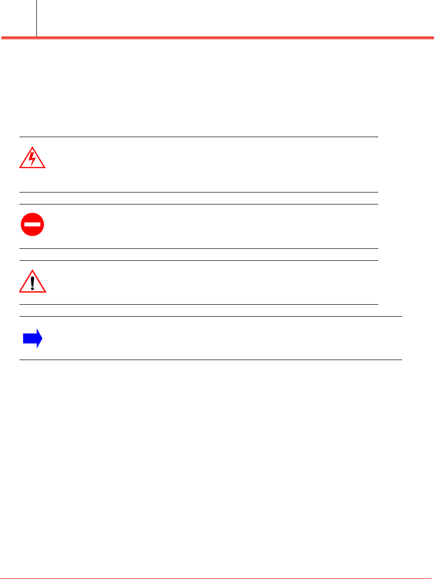
Warning: This symbol means the task may present an electrical hazard
that could cause bodily injury. Before you work on any equipment, you
must be aware of the hazards involved with electrical circuitry, and
familiarize yourself with standard practices for preventing accidents.
Caution: This symbol means that you must be careful. In this situation,
performing tasks incorrectly could result in equipment damage or loss of
data.
Danger: This symbol means that a task may present physical danger
associated with lifting and moving physical equipment. This includes
bodily injury and damage to system hardware.
Note: This symbol provides important or supplemental information about a
task that you are performing.

Preface
Apex Strand Small Cell
Installation Guide vii
Safety and Regulatory Agency Compliance
The product complies with the safety and regulatory agency standards listed below when
installed in accordance with this guide.
SAVE THIS MANUAL for Future reference: Refer for Service, and decommissioning
product. This documentation is to be used in conjunction with the specific product
installation guide that shipped with the product. Please refer to the Installation Guide,
Configuration Guide, or other enclosed additional documentation for further details.
Important Safety Instructions:
• Read these instructions
• Heed all warnings
• Follow all instructions
Additional Information: (Regulatory Model Number)
This product is assigned a Regulatory Model Number, which relates to the regulatory
aspects of the design. This Regulatory Model Number is the main product identifier in the
regulatory documents, test reports, and certifications. This number is not to be confused
with the marketing name(s) or product numbers.
Preface
Installation Guide
Installation Guide
viii
Product safety information
Symbols
Users who perform these tasks should be familiar not only with the Casa hardware and
cabling, but also with electronic circuitry, wiring practices, and safety precautions.
The following symbols appear in this guide. Before working on equipment, be aware of the
hazards involved with electrical circuitry and standard safety practices that can help
prevent accidents.
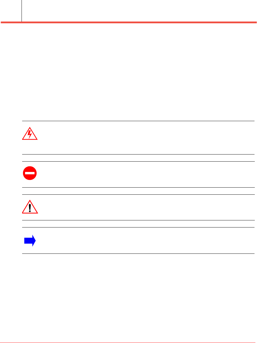
Warning: This symbol means the task may present an electrical hazard that
could cause bodily injury. Before you work on any equipment, you must be aware
of the hazards involved with electrical circuitry, and familiarize yourself with
standard practices for preventing accidents.
Caution: This symbol means that you must be careful. In this situation,
performing tasks incorrectly could result in equipment damage or loss of data.
ESD sensitive components.
Danger: This symbol means that a task may present physical danger associated
with lifting and moving physical equipment. This includes bodily injury and
damage to system hardware.
Note: This symbol provides important or supplemental information about a task
that you are performing.
Preface
Apex Strand Small Cell
Installation Guide ix
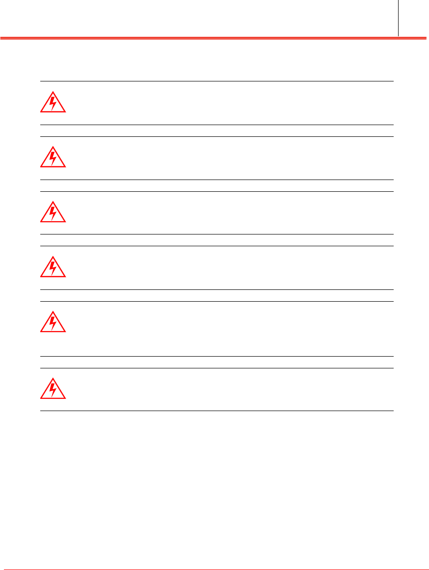
Read instructions and understand safety warnings
Warning: Read and understand the installation instructions and all safety
warnings before connecting the system to the power source. Failure to
understand safety precautions may result in injury.
Warning: Install only in accordance with national and local wiring
regulations. Failure to follow regulations may result in damage or injury.
Warning: Only trained and qualified personnel should be allowed to
install, replace, or service this equipment.
Warning: When installing or replacing the unit, the ground connection
must always be made first and disconnected last.
Warning: This equipment must be grounded. Never defeat the ground
conductor or operate the equipment in the absence of a suitably installed
ground conductor. Contact the appropriate electrical inspection authority
or an electrician if you are uncertain that suitable grounding is available.
Warning: Do not operate the unit near unshielded blasting caps or in an
explosive environment unless the device has been modified to be
especially qualified for such use.
Preface
Installation Guide
Installation Guide
x
Powering the node
Caution: The DAA Node draws AC power from the same coaxial cable
that may be used for data. This AC power comes from an external AC
power supply.
Warning: This product is powered by (40 - 90V) AC power over Coax.
Never connect more than one AC INPUT or the unit may be damaged.
Removed all internal AC jumpers, if installed, prior to connecting power to the
device
Warning: Take care when connecting units to the supply circuit so that
wiring is not overloaded. Install only in accordance with national and local
wiring regulations.
Caution: The operator must verify that the RF connector and cabling
types used are suitable to handle the calculated pass through current to
support powering other devices. (for example F-type connectors can only
handle up to 8amps.)
Warning: When configuring the unit, ensure all stingers, RF connectors,
and cables are properly rated to handle the AC electrical current.
Ensure that all enclosure connectors are rated IP67 or better.
Failure to do so may result in damage to the product.
Warning: This product requires short-circuit (over-current) protection, to
be provided as part of the CATV Power Supply installation. Install only in
accordance with national and local wiring regulations.
Caution: Attached cables and/or connectors should be IP67 rated.
Preface
Apex Strand Small Cell
Installation Guide xi
Supply circuit warning
Warning: To avoid electric shock, do not work on the system or connect
or disconnect cables during periods of lightning activity.
Caution: This Product generates radio frequency (RF) energy. To ensure
that your exposure to RF energy is within the FCC allowable limits for
occupational use, stay back 3 feet from the device.
Note: Ultimate disposal of this product should be handled according to
all national laws and regulations.

Preface
Installation Guide
Installation Guide
xii
Federal Communications Commission (FCC) statement
This device complies with FCC part 15 FCC Rules. Operation is subject to the
following two conditions:
1. This device may not cause harmful interference and
2. This device must accept any interference, including interference that may cause
undesired operation of the device.
FCC Warning
Changes or modifications not expressly approved by the party responsible for
compliance could void the user's authority to operate the equipment. Note: This
equipment has been tested and found to comply with the limits for a Class B digital
device, pursuant to part 15 of the FCC Rules. These limits are designed to provide
reasonable protection against harmful interference in a residential installation. This
equipment generates, uses and can radiate radio frequency energy and, if not installed
and used in accordance with the instructions, may cause harmful interference to radio
communications. However, there is no guarantee that interference will not occur in a
particular installation. If this equipment does cause harmful interference to radio or
television reception, which can be determined by turning the equipment off and on,
the user is encouraged to try to correct the interference by one or more of the
following measures:
• Reorient or relocate the receiving antenna.
• Increase the separation between the equipment and receiver.
• Connect the equipment into an outlet on a circuit different from that to which the
receiver is connected.
• Consult the dealer or an experienced radio/TV technician for help.
This device meets the FCC requirements for RF exposure in public or uncontrolled
environments.

Preface
Apex Strand Small Cell
Installation Guide xiii
Wi-Fi Compliance Statements:
This device contains FCC ID: PVH0965
Caution:
Any changes or modification could cause the module to cease to comply with FCC
rules part 15 and thus void the user's authority to operate the equipment.
§15.407 statement; in case of absence of information to transmit or operational failure
the module types ODIN-W2 will automatically discontinue transmission.
Maximum Permissible Exposure distance statement
Casa's fixed wireless base station products which are evaluated to determine RF
exposure levels and define the maximum permitted exposure (MPE) distance for each
device.
This system has been evaluated for RF exposure for Humans under 47 CFR §1.1307 ,
using American National Standards Institute ANSI c95.1 and KDB 447498 methods.
Based on these measurements and calculations, to maintain compliance for RF
exposure in the United States, the minimum separation distance is 3 feet (0.91 m) from
general bystanders.
EU Statement
This device has not been authorized as required by European Union Directives. This
device is not, and may not be, offered for sale or lease, or sold or leased, until
authorization is obtained.
Adequate measures must be taken during demonstrations to ensure that electromagnetic
disturbances are avoided. Special temporary authority may be required by local agencies
to operate the device

Preface
Installation Guide
Installation Guide
xiv
Contacting Casa
Corporate facility
Casa Systems, Inc.
100 Old River Road
Andover, MA 01810
Tel.: 978-688-6706
World Wide Web: www.casa-systems.com
Technical documentation
Casa Systems provides the following documentation set in PDF format, viewable
using current versions of Adobe Reader©. The latest documentation and revisions are
uploaded on a continued basis for Casa customers.
Contact Casa Technical Support or a Casa Sales Representative for assistance with
downloading selected Casa documentation PDFs.
Administrative and Configuration Guides
• Casa Systems – Apex Strand Small Cell Installation Guide (this document)
• Casa Systems – Apex Strand Small Cell Reference Guide
• Casa Systems – AeMS SNMP MIBs and Traps Reference
• Casa Systems – Apex Small Cell OM Counters Reference Guide
• Casa Systems – Apex Small Cell Parameters Reference Guide
• Casa Systems – Axyom Element Management System (AeMS) Administration
Guide
Preface
Apex Strand Small Cell
Installation Guide xv
Revision history
• 01.00.00 — July 2018
• 01.02.00 — September 2018
• 01.03.00 — October 2018
• 01.04.00 — December 2018
Supported software releases
The following Casa software release(s) are supported in this latest revision:
• 4.2.0 — August 2018
• 4.2.1 — September 2018
• 4.2.2 — October 2018
• 4.2.3 — December 2018
Conventions used in Casa documentation
Key Convention Function Example
boldface font Commands and keywords are in boldface. Enter abc
Italic font Emphasized terminology is in italics. burst profile
brackets [ ] Elements in square brackets are optional. [<ip_addr>]
braces {x | y | z} Indicates a required argument with a choice of
values; choose one.
{enabled | disabled}
brackets [x | y | z] Indicates an optional argument with a choice of
values; choose one.
[abc | 123]
vertical bar | Separates parameter values. Same as “or.” {TCP | TLS}
string A non-quoted set of characters. Do not use
quotation marks (“”) around the string as the string
will include the quotation marks.
abc
screen font CLI sessions and information the system displays
are in screen font.
CASA(config)#
boldface screen
font
Information you must enter is in boldface
screen font.
Preface
Installation Guide
Installation Guide
xvi
<variable> Arguments for which you supply values are
enclosed in angle brackets. Multi-word arguments
are indicated with underscore-separated words.
<as_number>
<value:value> Arguments may include a range of values, with the
minimum and maximum values separated by a
colon.
<0:65535>
Key Convention Function Example

Preface
Apex Strand Small Cell
Installation Guide xvii
Acronyms
Casa Systems manuals contain the following industry-standard and product-specific
acronyms:
3GPP 3rd Generation Partnership Project
AES Advanced Encryption Standard
CA Certificate Authority
CBC Cypher Block Chaining (encryption mode)
CDMA Code Division Multiple Access
CPE Customer Premises Equipment
C-RNTI Cell- Radio Network Temporary Identifier
CSG Closed Subscriber Group (ID in PLMN)
DES Data Encryption Standard
DH Diffie-Hellman
DHCP Dynamic Host Configuration Protocol
DRX Discontinuous Reception
DS Downstream
DSCP Differentiated Services Control Point
EAP Extensible Authentication Protocol
ECGI E-UTRAN Cell Global Identifier
ECI E-UTRAN Cell Identifier
eNB Evolved (E-UTRAN) Node B
EPC Evolved Packet Core
e-RAB E-UTRAN Radio Access Bearer
ESP Encapsulating Security Payload (of IPsec)
EUTRAN Evolved UMTS Terrestrial Radio Access Network
FQDN Fully Qualified Domain Name
GBR Guaranteed Bit Rate
GERAN Global System for Mobile Edge Radio Access Network
GGSN Gateway General Packet Radio Service Support Node
GigE Gigabit Ethernet
GPRS General Packet Radio Service
GRE Generic Router Encapsulation

Preface
Installation Guide
Installation Guide
xviii
GSM Global System for Mobile
GTP General Packet Radio Service Tunneling Protocol
GTPv2 GPRS Tunneling Protocol Version 2
HFC Hybrid Fiber-Coaxial
HMAC Hashing Message Authentication Code
HNB Home NodeB Gateway
HNB-GW Home NodeB Gateway
HPLMN Home Public Land Mobile Network
HSDPA High-Speed Downlink Packet Access
HSUPA High-Speed Uplink Packet Access
IKE Internet Key Exchange
IKEv2 Internet Key Exchange Protocol version 2
IMC International Mobile Communications
IMS IP Multimedia Subsystem
IMSI International Mobile Subscriber Identity
IPsec Internet Protocol Security
IPv4 Internet Protocol Version 4
IPv6 Internet Protocol Version 6
LTE Long Term Evolution
LTE-A Long Term Evolution Advanced (4G)
MCC Mobile Country Code
MIMO Multiple-Input Multiple-Output
MNC Mobile Network Code
OAKLEY Diffie-Hellman key exchange groups
OFDMA Orthogonal Frequency Division Multiple Access
PKI Public Key Infrastructure
PLMN Public Land Mobile Network
PSK Pre-Shared Key
QCI Quality of Service Class Identifier
QoS Quality of Service
RAT Radio Access Technology
RTP Real-time Transport Protocol

Preface
Apex Strand Small Cell
Installation Guide xix
S1-AP S1 Application Protocol
S1-MME S1 Mobility Management Entity
S1-U S1 User plane interface
SA Security Association (for IPsec)
SCTP Stream Control Transmission Protocol
SeGW Security Gateway
TAC Tracking Area Code
TAI Tracking Area Identity
TCP Transmission Control Protocol
TD-SCDMA Time Division Synchronous Code Division Multiple Access
UDP User Datagram Protocol
UE User Equipment
UMTS Universal Mobile Telecommunications Systems
UTRAN Universal Terrestrial Radio Access Network
X.509 Public Key Infrastructure encryption standard
XGigE XGigabit Ethernet

Preface
Installation Guide
Installation Guide
xx
Apex Strand Small Cell
1-1
Chapter 1. Installing the Apex Strand
Small Cell
This chapter covers the procedures for installing and connecting the Apex Strand. It
includes the following topics:
Topic Page
Safety guidelines 1-2
Required tools 1-3
Approved antenna(s) 1-3
Components of the Apex Strand Small Cell 1-4
Power inputs 1-6
Fuse location 1-8
Network connections 1-9
Unpacking the system 1-10
Installing the Apex Strand 1-11
Installation prerequisites 1-11
Powering the Apex Strand 1-12
Apex Strand Kill Switch 1-13
Selecting the installation location 1-14
Hanging the Apex Strand 1-15
RF provisioning 1-16
Connect the power source 1-16
Verify the Strand Operation 1-16
Closing and sealing the enclosure 1-17
Torquing the Apex Strand bolts 1-17
System management 1-17
Safety guidelines
Installation Guide
Installation Guide
1-2
Safety guidelines
This section provides general safety guidelines during the equipment installation and
operation.
Be sure to follow these important electrical guidelines:
• Always unplug or disconnect the power cable before installing or removing the
unit.
• Do not work alone if potentially hazardous conditions exist.
• Never assume that power is disconnected from a circuit. Always check.
• If an electrical accident occurs, proceed as follows:
— Use caution; do not become a victim yourself.
— Turn off power to the system.
— If possible, send another person to get medical aid. Otherwise, assess the
condition of the victim and then call for help.
— Determine whether the person needs rescue breathing or external cardiac
compressions; then take appropriate action.
Warning: Only trained and qualified personnel should install, replace, or
service this equipment.
Do not work on the system or connect or disconnect cables during
lightning activity.

Required tools
Apex Strand Small Cell
Installing the Apex Strand Small Cell 1-3
Required tools
The standard lineman tool set for installing telecommunications equipment outdoors
includes a variety of open end wrenches that are necessary for the Apex Strand Small
Cell enclosure installation.
Required installation components
Following components are not provided by Casa, but needed for successful
installation:
• Kill switch supplied by CableServ (part #???)
• Kill switch alarm connector, supplied by Chogori, USA (Vendor
part#23003536-01)
• Hardline coax input
Approved antenna(s)
The following antenna(s) is approved for use with this device:
Wi-Fi Antenna(s):
TAOGLAS
Model: GW.26.0112.HT
Frequency: 2.4-2.5 GHz
Peak Gain: 1.2 dBi,
Length: 84mm
Impedance: 50 ohm
Components of the Apex Strand Small Cell
Installation Guide
Installation Guide
1-4
Components of the Apex Strand Small Cell
The Apex Strand Small Cell is designed to be installed in an aerial outside plant
environment of the multiservice network operator. It is designed specifically for a
harsh environment.
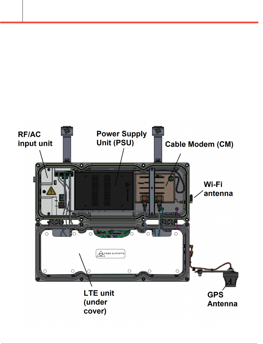
Figure 1-1 shows the location of the five major components that make up the Apex
Small Cell unit. Only the Power Supply Unit is designed to be field replaceable. All
other parts should be serviced only by an authorized service location.
Figure 1-1. Inside the Apex Strand Small Cell unit
Components of the Apex Strand Small Cell
Apex Strand Small Cell
Installing the Apex Strand Small Cell 1-5
Field Replacement Units
• Power Supply Unit (PSU) which converts AC to DC voltage
Non-Field Replaceable Units
• RF/AC input unit (includes the input plugin and surge suppressor)
• LTE unit
• Cable Modem (CM)
• GPS antenna
• Wi-Fi antenna
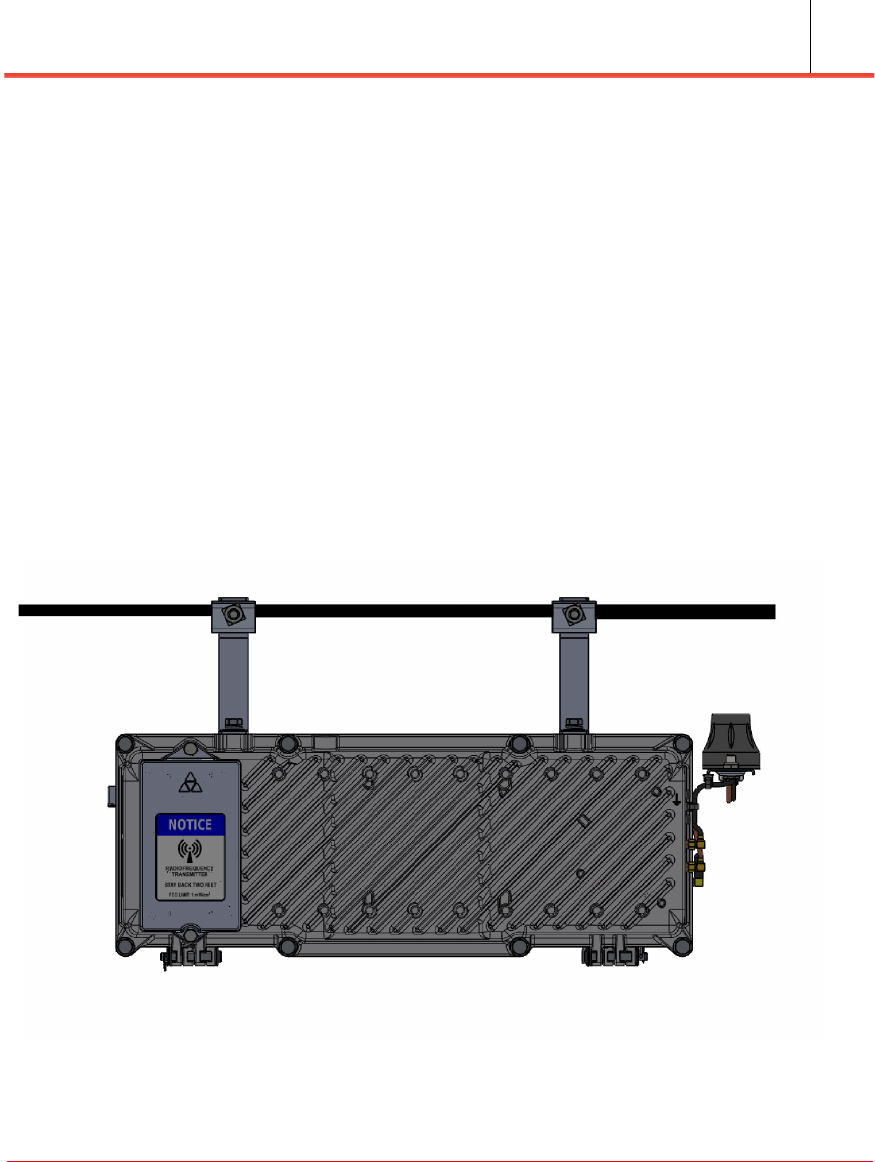
Figure 1-2 shows the unit in its closed (normal) state as it would be oriented in its
designed operational position.
Figure 1-2. Apex Strand Small Cell unit
Power inputs
Installation Guide
Installation Guide
1-6
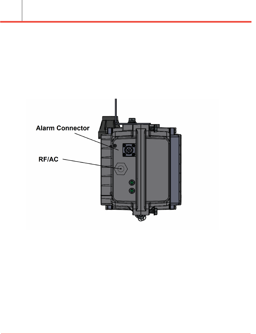
Power inputs
Located on the side of the unit are two connections (see Figure 1-3):
• RF/AC input connector
• Alarm connector
Figure 1-3. Power inputs
RF/AC input connector
In order to power the unit from the existing coaxial cable plant, the enclosure supports
powering from 45-90 VAC via the combined RF/AC input. This input brings both the
AC system power but also the RF communications connection.
This unit supports a standard 5/8 inch threaded connector used in the operators outside
plant environment. Because of outdoor exposure you must use hardline coax input.
Power inputs
Apex Strand Small Cell
Installing the Apex Strand Small Cell 1-7
Alarm Connector
The alarm connector is located above the RF/AC input connector. It provides a
signaling connections for communications from the Small Cell to the alarm
monitoring system via the RF communications path established by the unit.
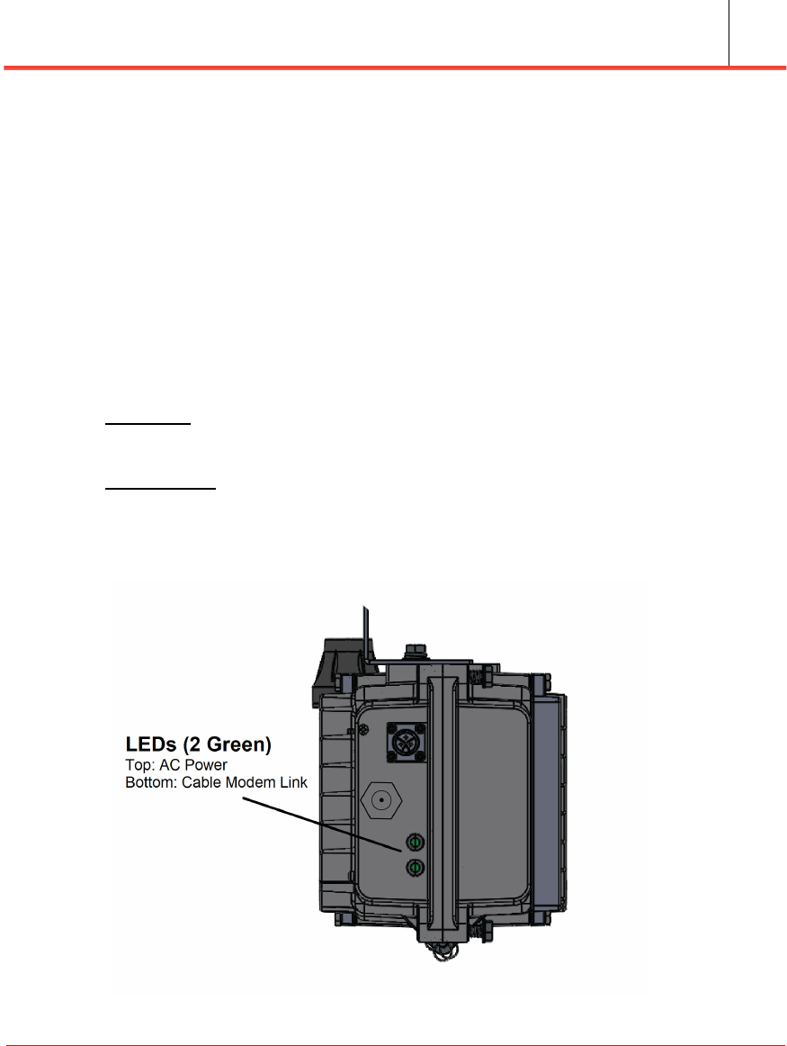
Status LEDs
Below the RF/AC connector are two status monitoring LEDs that are visible from the
ground during daylight hours (see Figure 1-4). The LEDs are intended to give the
technician an indication of the overall health of the power and communications
network between the internal devices and the edge DOCSIS equipment.
Top LED: Provides AC/DC power status of the unit. Solid green when the status is in
a normal state.
Lower LED: Provides status of the DOCSIS modem link. Solid green when the status
is in a normal state.
Figure 1-4. LEDs
Fuse location
Installation Guide
Installation Guide
1-8
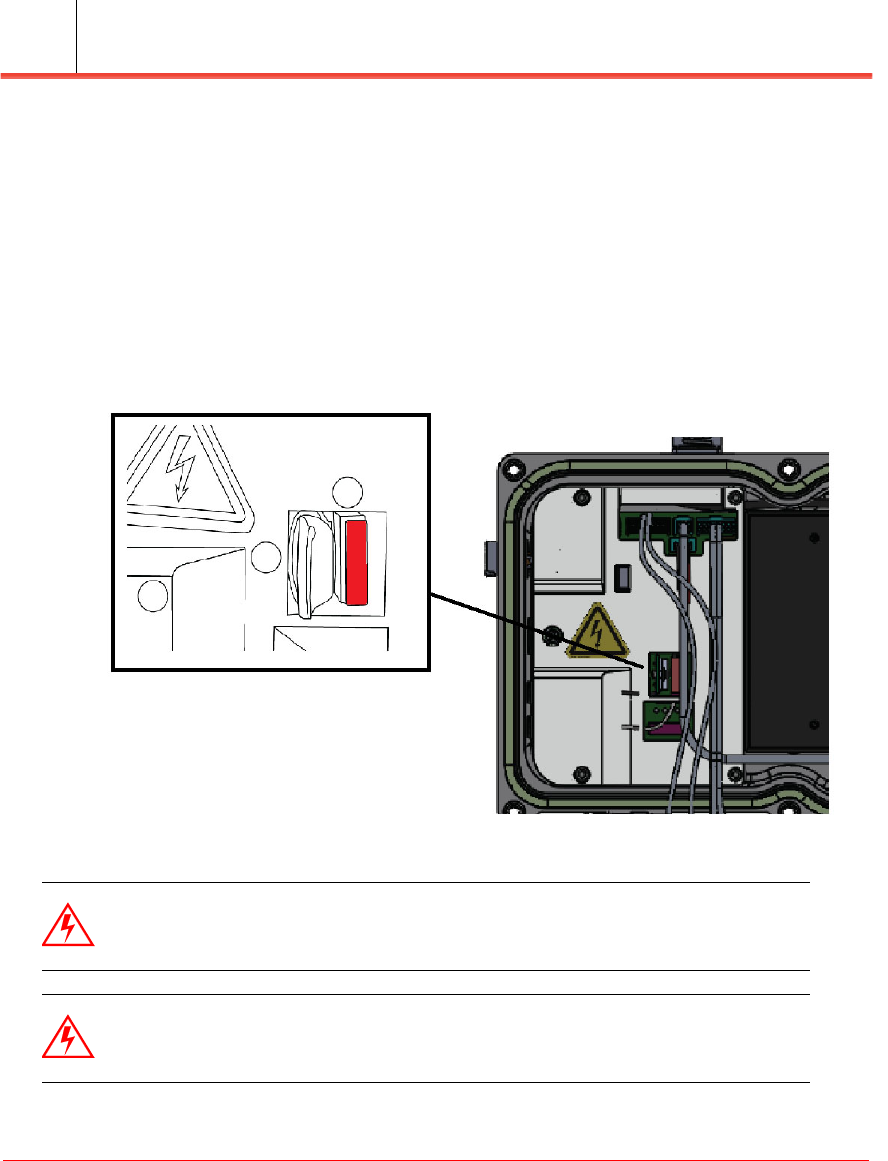
Fuse location
After opening the unit, there is a fuse slot located on the interface board in the base of
the unit. This unit comes populated with a 7.5a fuse that can be replaced as a
serviceable protection device (see Figure 1-5). Adjacent to the unit are the pluggable
surge suppressor devices. These are not field changeable units and should only be
replaced by a qualified technician.
Figure 1-5. Fuse location
Warning: To avoid electric shock, ensure the single AC input coaxial cable
feed is properly identified and disconnected prior to servicing.
Warning: Do not install more than one fuse in the Apex Strand Small Cell. Do
not install the Apex Strand Small Cell if there is no fuse inserted.

Network connections
Apex Strand Small Cell
Installing the Apex Strand Small Cell 1-9
Network connections
The Apex Strand supports the following network connections:
• The Apex Strand is connected to the operators network through the HFC network.
• The Apex Strand connects to the CATV network via the hard line coax
connection. A user connects via LTE wireless through the Apex Strand using the
CATV network as the back haul to the internet.
• The CM inside the Apex Strand unit is DOCSIS 3.1 compliant. The RF/AC
connection to the Apex Strand needs to be weatherproof.
• The GPS antenna comes fixed on top of the Apex Strand. It is mounted on top of a
4 inch long arm, which can be horizontally rotated up to 180 degrees from its
initial position. The GPS antenna must have an unobstructed view towards the
sky.
• The Wi-Fi Antenna comes fixed on the unit. The antenna should point downward
(towards the street) for maximum efficiency. The Wi-Fi antenna can be vertically
rotated 360 degrees.
Unpacking the system
Installation Guide
Installation Guide
1-10
Unpacking the system
When the system arrives at your installation site, you need to carefully unpack the
system and other items included with the shipment. Check the shipping box for any
exterior damage.
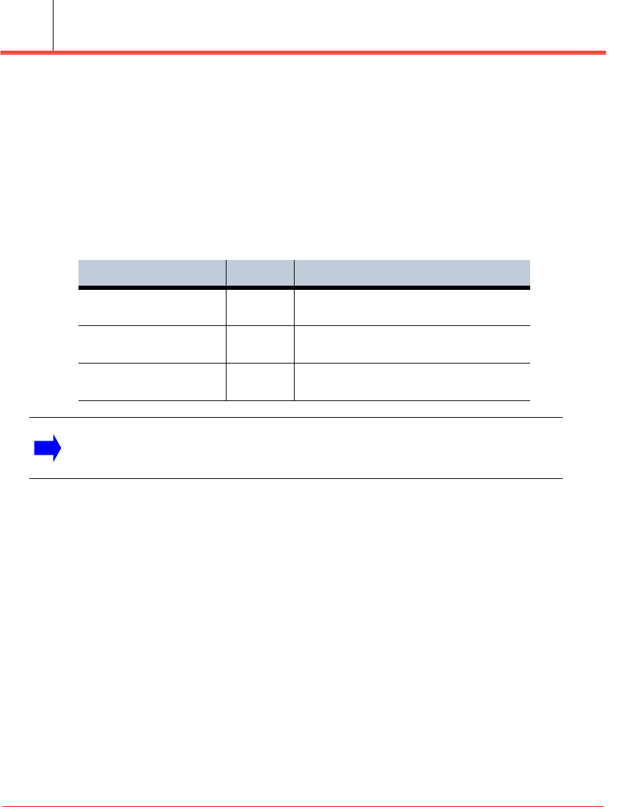
Table 1-6 provides a list of materials included with the Apex Strand:
Table 1-6. Apex Strand contents
Item Quantity Description
Apex Strand unit 1 Metal unit with fins with GPS antenna
installed
Mounting brackets 2 Brackets that allows the unit to hang from
the strand
Mounting bolts/nuts 2 Used to tighten the mounting brackets
onto the strand
Note: If damage is present, notify the shipping company and Casa Systems
immediately for a return material authorization, if necessary.
Installing the Apex Strand
Apex Strand Small Cell
Installing the Apex Strand Small Cell 1-11
Installing the Apex Strand
Installation prerequisites
The following prerequisites must be satisfied prior to installing the Apex Strand:
• Ensure required cables for connecting the unit are available.
• Clear the installation location considering the required GPS clearance signal.
Warning: This device is intended for installation and operation only by
qualified and well-trained service personnel. Ordinary users are not to have
access to any part of this product. Product must be mounted only in locations
where access is possible only by trained personnel. Product should never be
mounted on a house/dwelling where an ordinary, non-trained person must take
into account the possibility of a home owner conducting maintenance
(painting, cleaning, etc). on their home while using a ladder. In addition, the
same requirements apply to commercial locations. Access by non-trained
personnel shall not be possible and only mounting locations that prevent
access by a non-trained person are acceptable.
Warning: To avoid electric shock, verify that the internal fuse is not installed
in the unit. See “Fuse location” on page 1-8.
Installing the Apex Strand
Installation Guide
Installation Guide
1-12
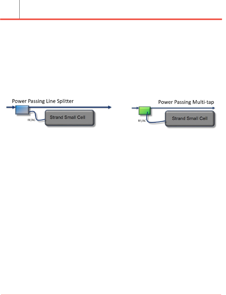
Powering the Apex Strand
The Apex Strand is powered via the RF/AC connection as shown in Figure 1-7. These
cables can either be from a power passing line splitter via either an RG6 or hardline
cable depending on the distance following the operators construction practices.
This unit can also be powered from a power passing multi-tap device using RG6 or
larger flexible cable following the operators installation practices.
Figure 1-7. Apex Strand power options
Installing the Apex Strand
Apex Strand Small Cell
Installing the Apex Strand Small Cell 1-13
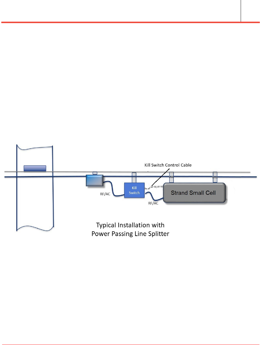
Apex Strand Kill Switch
The Apex Strand can be installed using a Kill Switch (provided by the operator) that is
installed between the power supply and the Apex Strand as shown in Figure 1-8. This
is an example of the connections for a typical installation utilizing a kill switch. Or,
this unit can be operated without the kill switch if desired. This equipment is required
to be installed per the operators specifications to meet the required local installation
practices.
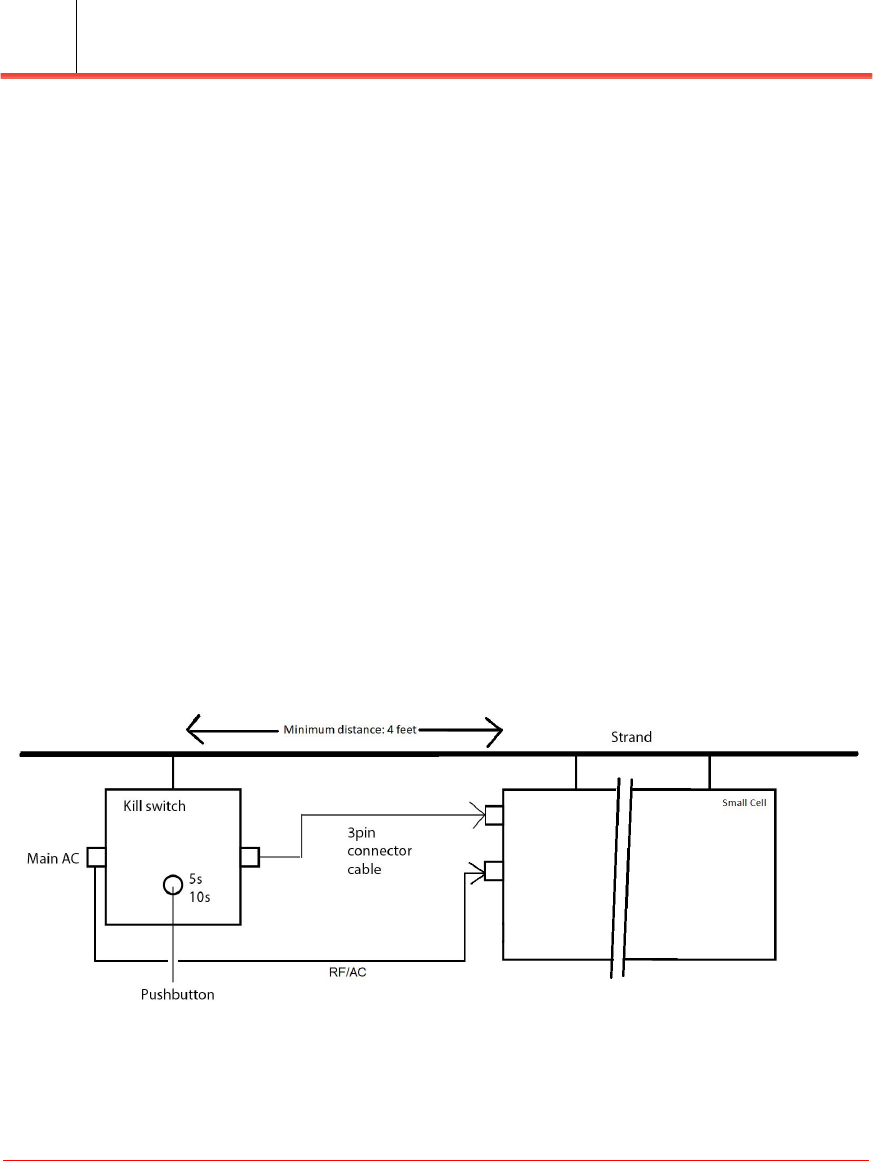
The Kill Switch controls power and RF connectivity to the Strand unit. When the
power to the Strand unit is on and the button is pressed on the Kill Switch, power to
the Strand unit will be disconnected after 10 seconds.
Figure 1-8. Apex Strand Kill Switch
Installing the Apex Strand
Installation Guide
Installation Guide
1-14
Selecting the installation location
The Apex Strand is designed for installation areas having above-ground utilities. The
Apex Strand can be installed on a strand wire with accessibility to the coaxial cable
output and system power source. Figure 1-9 shows the a typical Strand Installation.
These units are designed to be mounted in a HORIZONTAL only position and is not
designed to be mounted vertically. All hardware connections that are made in the field
need to be torqued to 10 ft/lbs.
Preparing the installation site
• Disconnect AC power to the work location.
• Access the installation location to ensure that it meets the operators requirements
for the GPS antenna.
• Create a connection to the HFC network.
• Prepare the cable(s) that will connect to the Apex Strand as required per the
network operators guidelines.
Figure 1-9. Apex Strand installation
Installing the Apex Strand
Apex Strand Small Cell
Installing the Apex Strand Small Cell 1-15
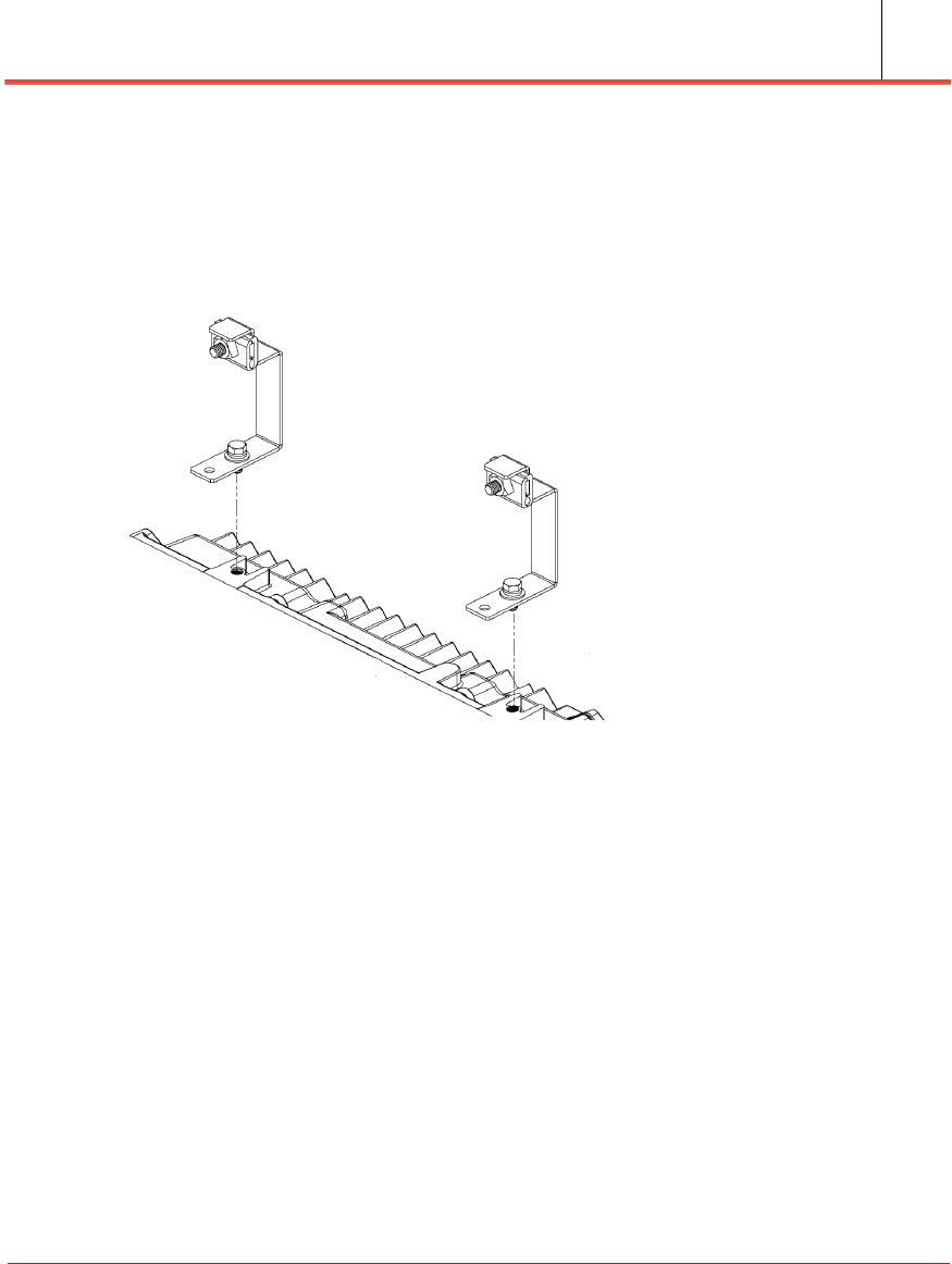
Hanging the Apex Strand
1. Install the strand offset hanger brackets onto the strand unit as shown in
Figure 1-10 using the provided hardware.
Figure 1-10. Installation brackets
2. Hang the closed small cell from the strand as shown in Figure 1-9, and secure the
hanging brackets to the operators support strand.
3. Torque the strand clamps to 10 ft/lbs.
4. Open the Apex Strand by loosening the retaining bolts around the enclosure,
carefully open the lid, and locate the fuse on the RF/AC input section.
5. Install the appropriate RF plugin in the attenuator slot per installation guidelines
provided by the local design team.

Installing the Apex Strand
Installation Guide
Installation Guide
1-16
RF provisioning
1. Before applying power to the Apex Strand, a qualified technician should verify
transmit levels at the tap location.
2. Determine target transmit levels based on the specific installation location.
3. Verify transmit level of the cable modem is in the range of +35 to +51 dBmv.
Connect the power source
1. Connect the power cable (hardend coax line) to the Apex Strand unit. Ensure the
weather sealing of the outdoor housing connector per local installation guidelines.
2. If you are using a Kill Switch in your installation, connect the Kill Switch 3 pin
connector cable to the Apex Strand alarm connector input (see Figure 1-3).
3. Install the fuse inside the Strand unit.
4. Close the cover to the Strand unit and tighten the bolts based on the torque
recommendations (see “Closing and sealing the enclosure” on page 1-17).
5. Move away from the Strand unit to a safe distance and reconnect the power to the
work area.
6. Verify the power LED status on the Kill Switch and/or on the Apex Strand.
Verify the Strand Operation
1. Once AC power is applied to the Apex Strand, verify that the Green LED on the
side of the unit is lit (see Figure 1-4). Wait several minutes for the Apex Strand to
boot up and make an attempt to make a data connection to the HFC.
2. Coordinate with the operator's NOC to bring up the data connection to the Apex
Strand, which may require adjusting the attenuation settings. The Apex Strand
ships with a 0dB attenuator installed. It is up to the NOC and the installer to
achieve the optimal signal level.
3. Once the NOC has verified that you have a connection to the Apex Strand's cable
modem, and that it can recognize a CPE and verify the CM status LED is green.
4. The LTE unit is ready to connect to the Sprint network.
System management
Apex Strand Small Cell
Installing the Apex Strand Small Cell 1-17
Closing and sealing the enclosure
All Apex Strand enclosures are weather and electronically protected using both an
Environmental and EMI rubber seal integrated into the enclosure halves. Retention
bolts are held in place by lugs on the outside of the enclosure.
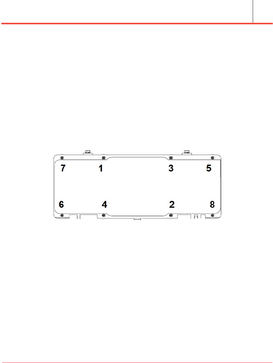
Torquing the Apex Strand bolts
Using an open-end 1/2 inch wrench or socket, tighten the bolts on the Apex Strand to
a final torque of 50 in lbs/5.6 Nm in the sequence shown in Figure 1-11.
Figure 1-11. Apex Strand bolt torquing sequence
System management
The Apex Strand Small Cell is designed for remote system management via the
AeMS. In case of loss of network connectivity the unit supports some diagnostic
service via on board Wi-Fi.
The Apex Strand appears as a CM and a CPE device in the HFC network. The internal
CM connects to the HFC network as a standard device.

System management
Installation Guide
Installation Guide
1-18


Apex Strand Small Cell
Installation Guide
© 2018 Casa Systems, Inc.
All rights reserved.
DOC-3077-01
Document Revision 1.04.00
December 2018
Printed in United States of America
100 Old River Road
Andover, MA 01810
USA
978-688-6706