Aztech Technologies DSL5005EN ADSL2+ 4-Ports 150 Mbps Wireless-N Modem Router User Manual DSL5005EN v0 3
Aztech Technologies Pte Ltd. ADSL2+ 4-Ports 150 Mbps Wireless-N Modem Router DSL5005EN v0 3
UserManual.wiki
>
Aztech Technologies
>
DSL5005EN User Manual
Users Manual
Navigation menu
Upload a User Manual
Namespaces
Wiki Guide
HTML
PDF
Info
Views
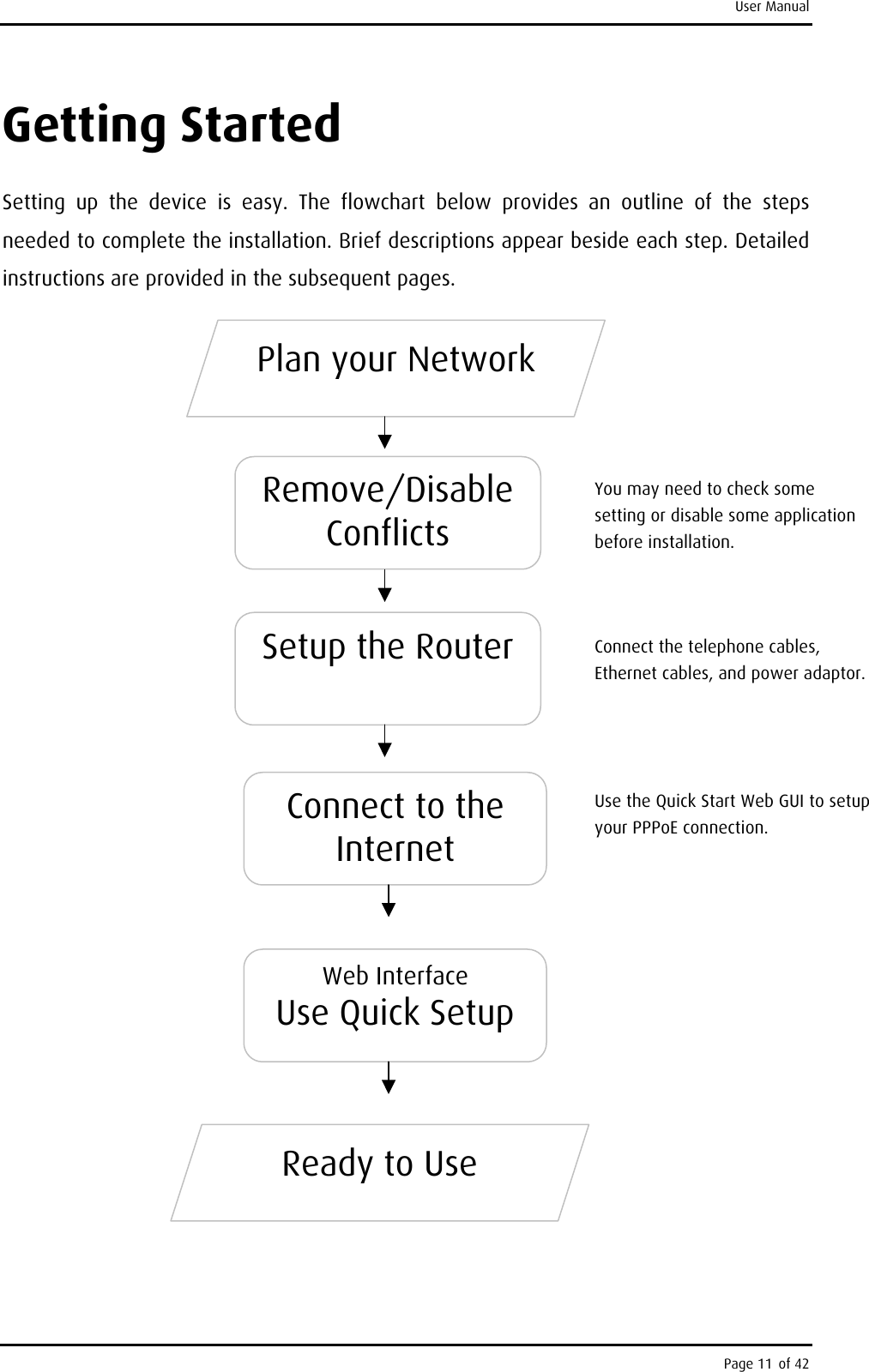
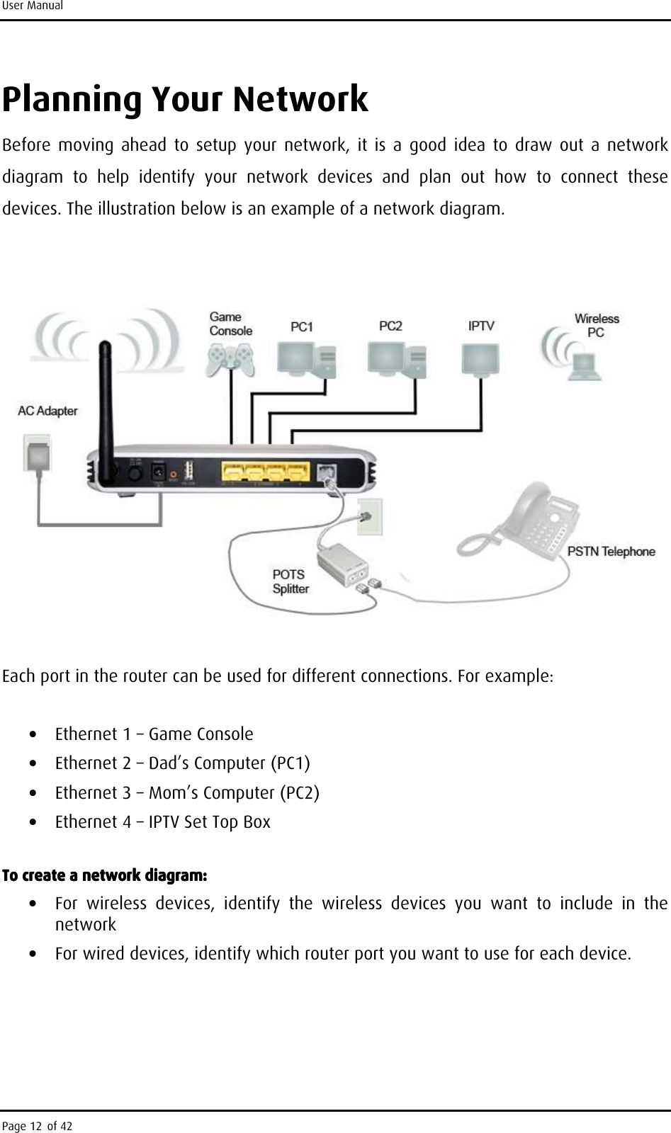
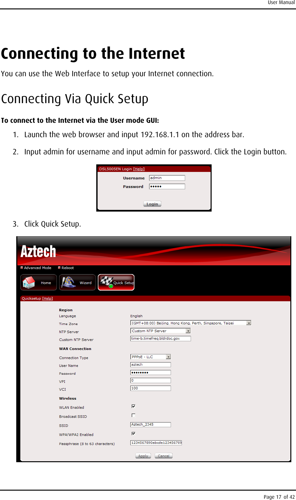
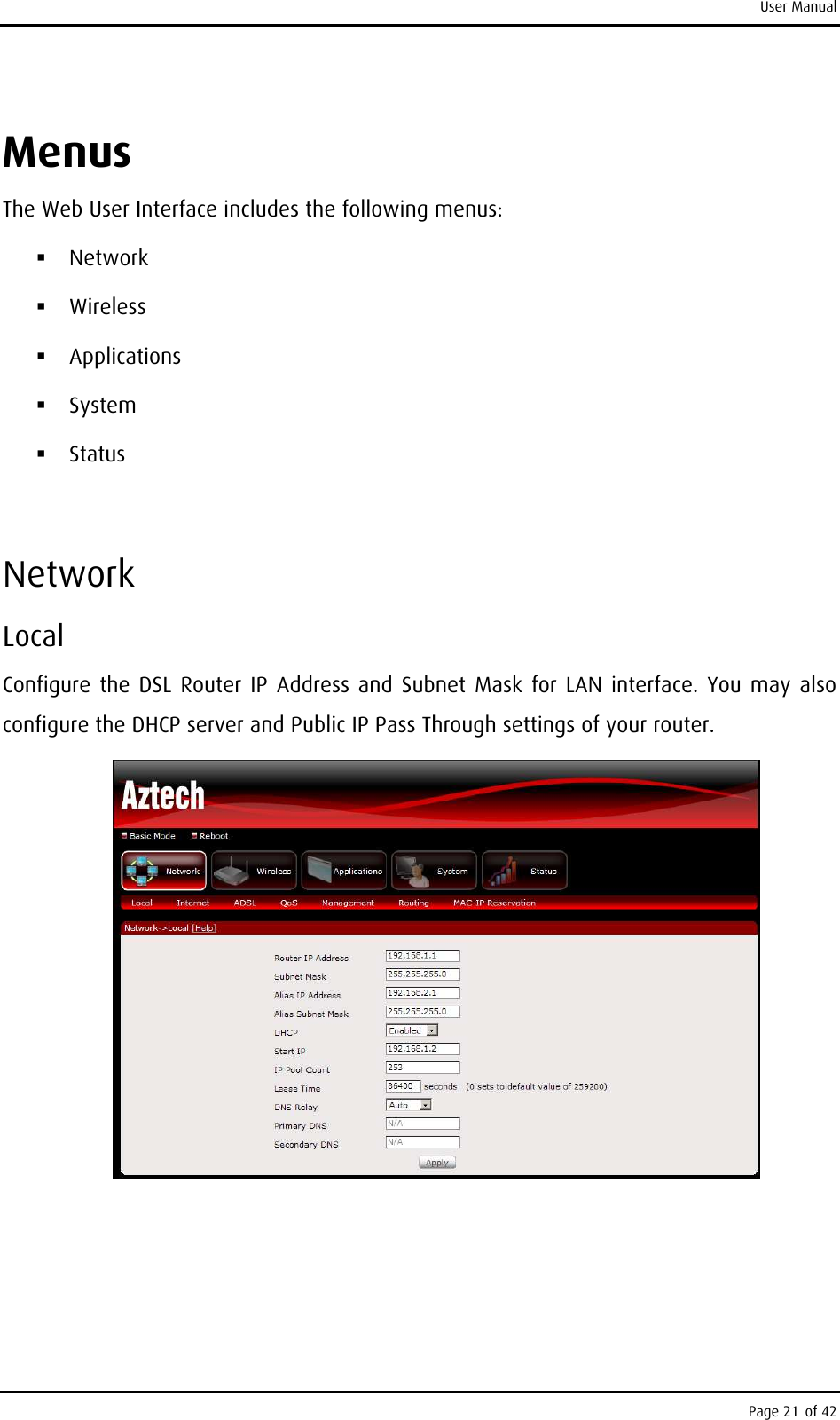
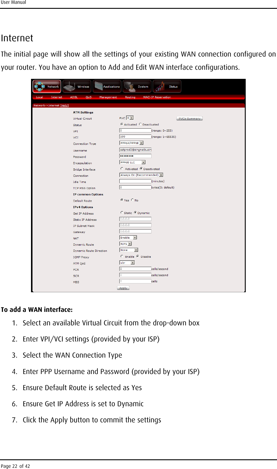
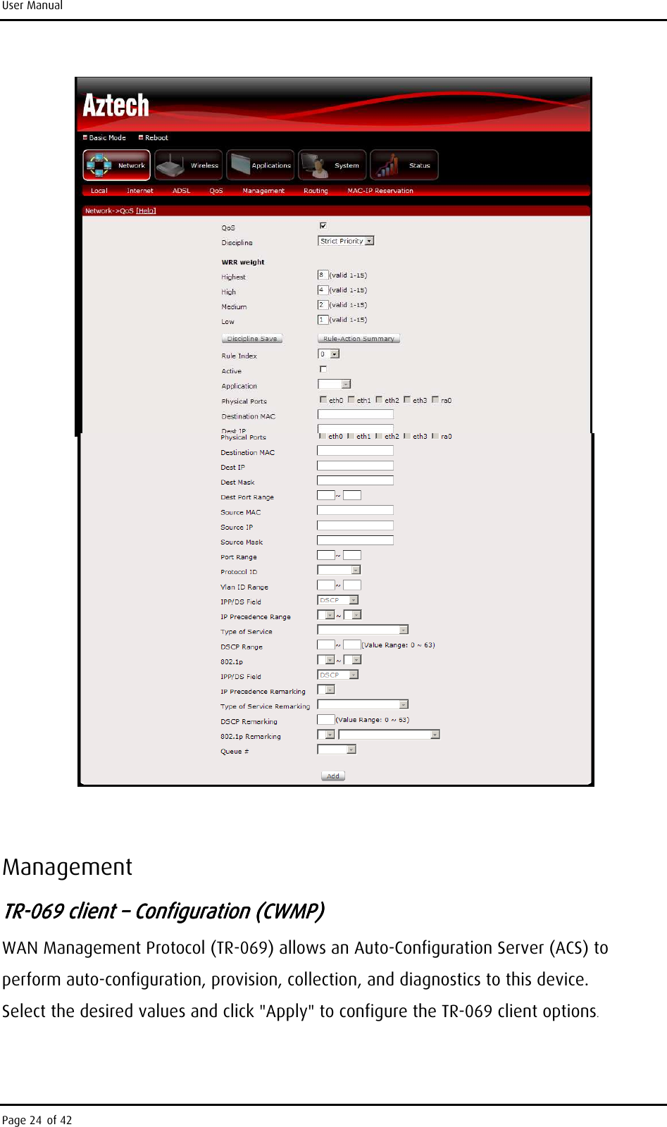
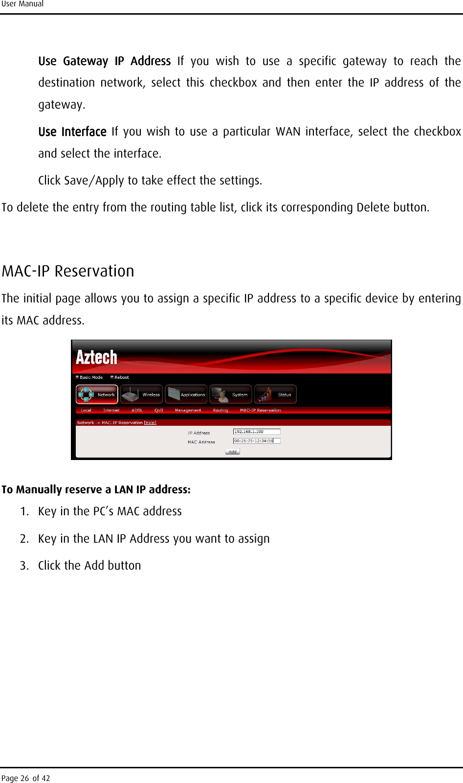
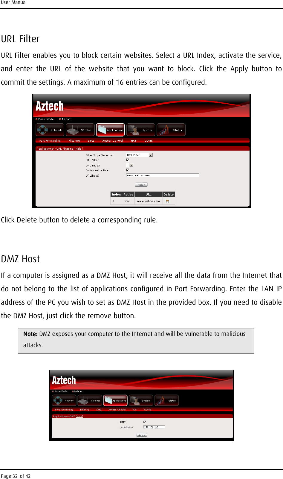
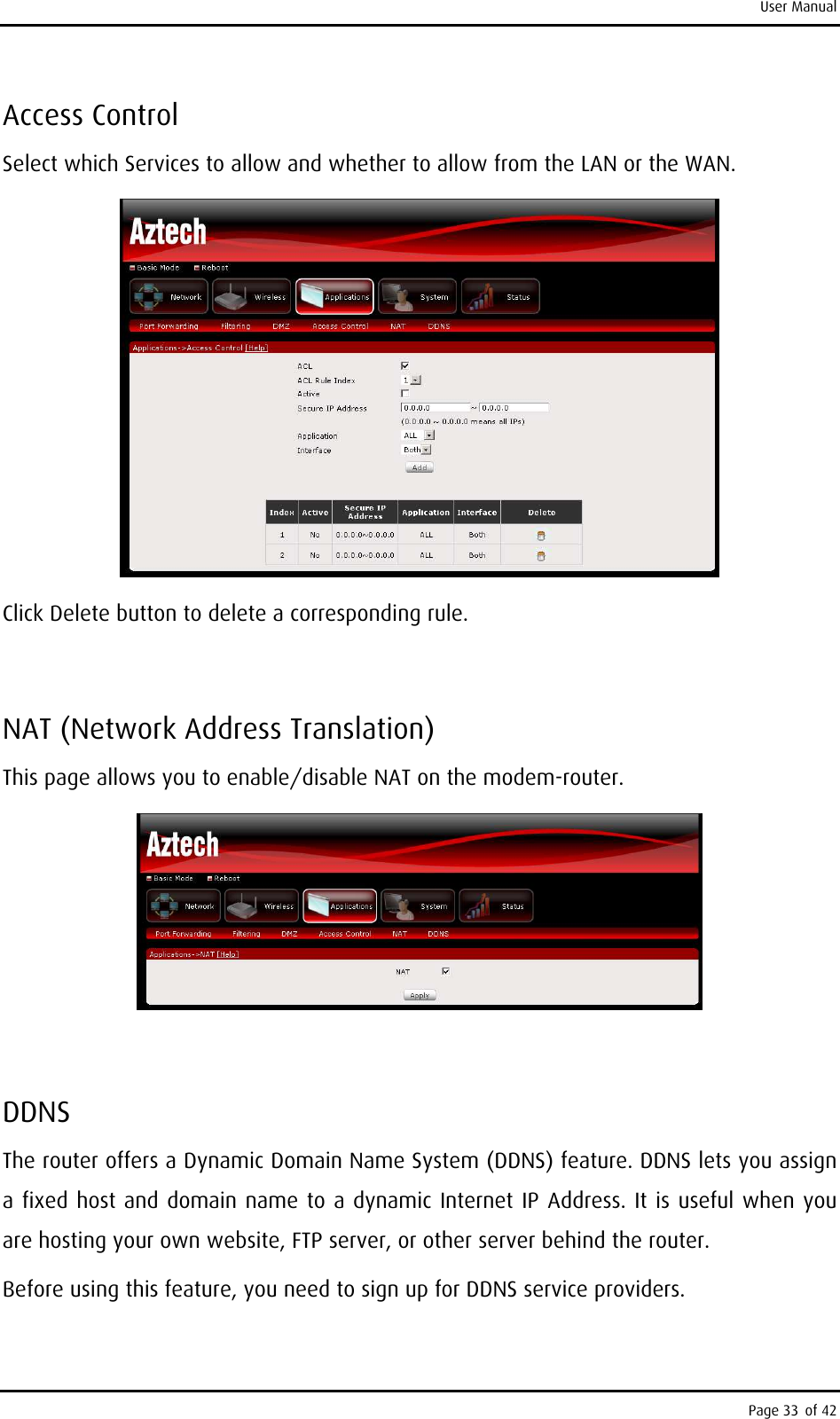
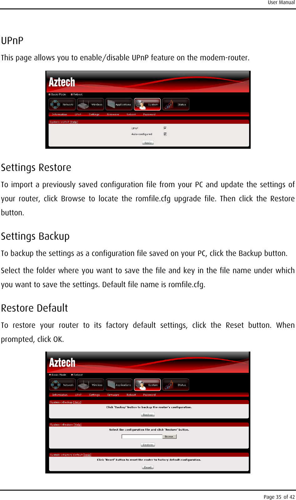
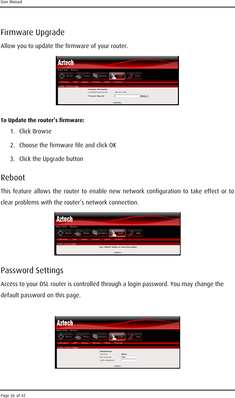
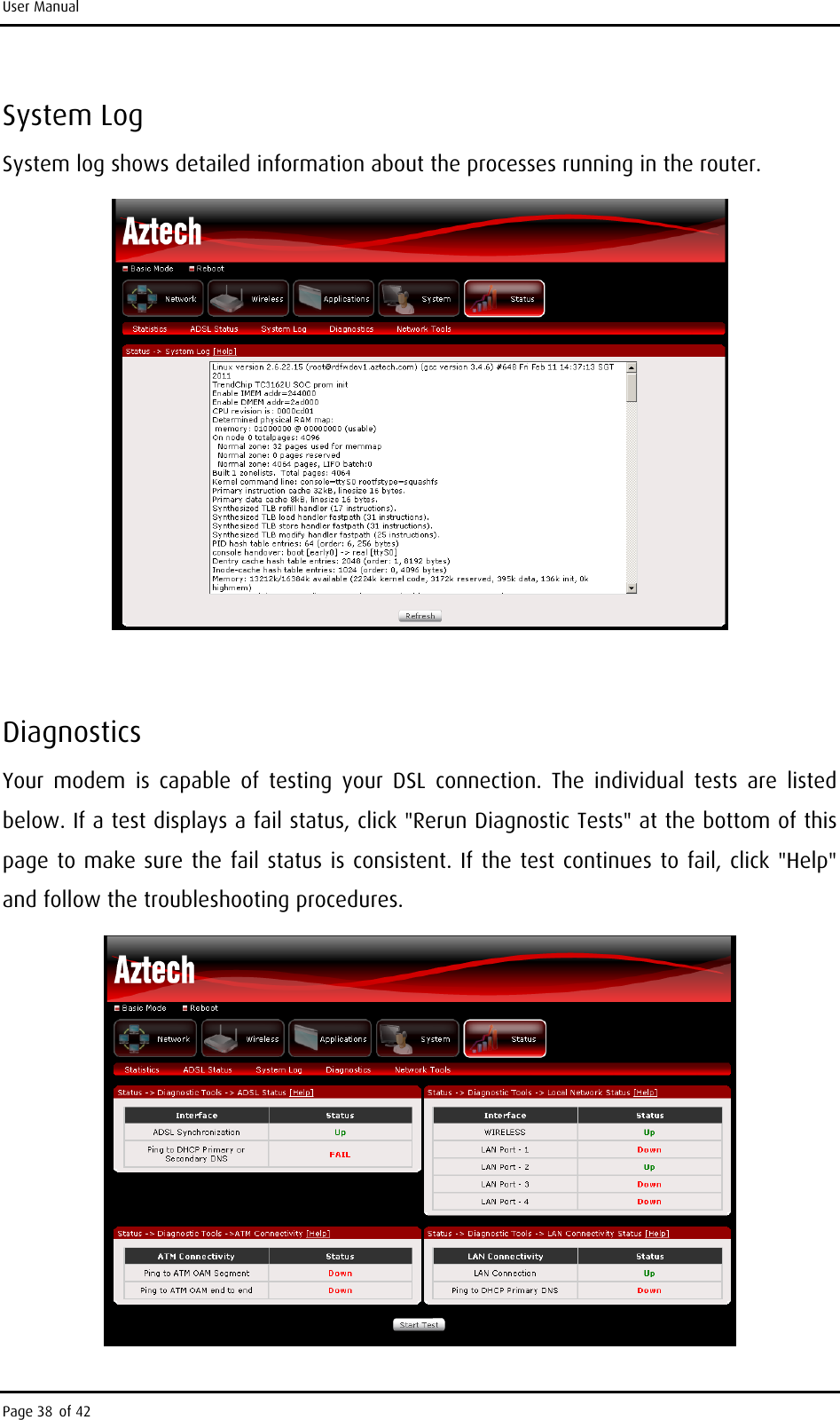
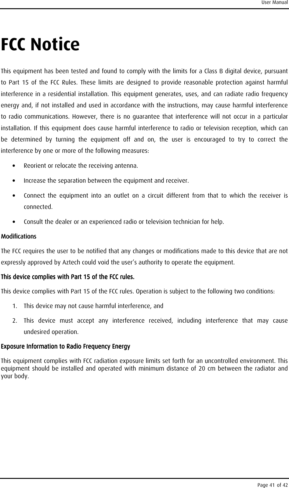
User Manual
Discussion / Help
Navigation


![User Manual Page 42 of 42 Customer InfoCustomer InfoCustomer InfoCustomer Informationrmationrmationrmation 1. This equipment complies with Part 68 of the FCC rules and the requirements adopted by the ACTA. On bottom of this equipment is a label that contains, among other information, a product identifier of [US:4J2DL01BDSL5005EN]. If requested, this number must be provided to the telephone company. 2. If this equipment [ADSL2+ 4-Ports 150Mbps Wireless-N Modem Router] causes harm to the telephone network, the telephone company will notify you in advance that temporary discontinuance of service may be required. But if advance notice isn’t practical, the telephone company will notify the customer as soon as possible. Also, you will be advised of your right to file a complaint with the FCC if you believe it is necessary. 3. The telephone company may make changes in this facilities, equipment, operations or procedures that could affect the operation of the equipment. If this happens the telephone company will provide advance notice in order for you to make necessary modification to maintain uninterrupted service. 4. If you experience trouble with this equipment, you disconnect it from the network until the problem has been corrected or until you are sure that the equipment is not malfunctioning. 5. Please follow instructions for repairing if any (e.g. battery replacement section); otherwise do not alternate or repair any parts of device except specified. 6. Connection to party line service is subject to state tariffs. Contact the state public utility commission public service commission or corporation commission for information. 7. If the telephone company requests information on what equipment is connected to their lines, inform them of: a. The telephone number that this unit is connected to, b. The ringer equivalence number [0.1B] c. The USOC jack required [RJ11C], and d. The FCC Registration Number [US:4J2DL01BDSL5005EN] Items (b) and (d) are indicated on the label. The ringer equivalence number (REN) is used to determine how many devices can be connected to your telephone line. In most areas, the sum of the RENs of all devices on any one line should not exceed five (5.0). If too many devices are attached, they may not ring properly. Service RequirementsService RequirementsService RequirementsService Requirements In the event of equipment malfunction, all repairs should be performed by our Company or an authorized agent. It is the responsibility of users requiring service to report the need for service to our Company or to one of our authorized agents. Service can be facilitated through our office at: Aztech Labs IncAztech Labs IncAztech Labs IncAztech Labs Inc 4005, Clipper Court, Fremont, CA, 94538. 510-683-9800](https://usermanual.wiki/Aztech-Technologies/DSL5005EN/User-Guide-1433978-Page-42.png)