AzureWave Technologies AM691NF IEEE 802.11 a/b/g/n Wireless LAN and Bluetooth Combo LGA Module User Manual AW AM691NF manual For FCC rev2
AzureWave Technologies, Inc. IEEE 802.11 a/b/g/n Wireless LAN and Bluetooth Combo LGA Module AW AM691NF manual For FCC rev2
Contents
User Manual.pdf
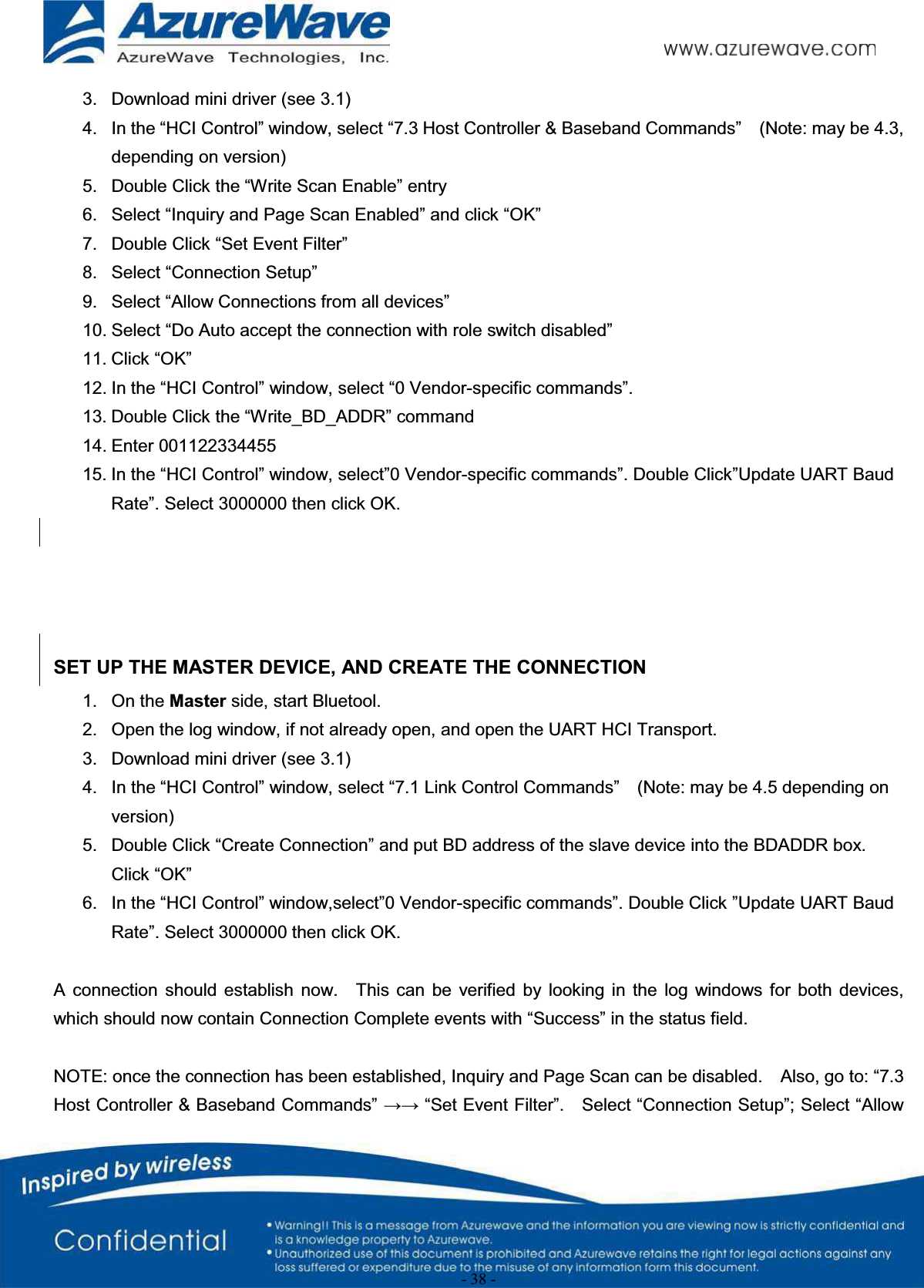
![- 6 -DRIVER INSTALLATION (IN LINUX)•First prepare the Broadcom’s Linux package, and put it in the “home” folder.•Open the Terminal, enter the command: sudo su and password.•Enter cd /home/username/5.90.195.26.3/open-src/src/dhd/linux•Enter make dhd-cdc-sdmmc-gpl to generate the dhd.ko file in /home/username/5.90.195.26.3/open-src/src/dhd/linux/dhd-cdc-sdmmc-gpl-2.6.32-21-generic•EnterInsmod /(path of dhd.ko file)firmware_path=/(path of firmware file) nvram_path=/(path of nvram file) to enable.•Enter rmmod dhd to disable•2-2. Throughput TestCONNECTING TO WIRELESS NETWORKSThe examples in the following sections illustrate how to connect to both infrastructure and ad hoc networks, including Infrastructure networks that use no security, WEP security, and WPA/PSK and WPS2/PSK security.SCANNING FOR WIRELESS NETWORKSTo force the dongle to scan•Run wl scan.To force the dongle to return the results of the scan•Run wl scanresults.Example results returned when an AP is found:•SSID: “Eval4325”•Mode: Managed: RSSI: -48 dBm noise: -105 dBm Channel: 1•BSSID: 00:10:18:90:2E:C1 Capability: ESS ShortSlot•Supported Rates: [ 1(b) 2(b) 5.5(b) 11(b) 18 24 36 54 6 9 12 48 ]Example results returned when an ad hoc network is found:•SSID: “ADHOC#1”•Mode: Ad Hoc RSSI: -41 dBm noise: -105 dBm Channel: 1•BSSID: B2:51:28:6B:3C:A1 Capability: IBSS•Supported Rates: [ 1(b) 2(b) 5.5(b) 11(b) ]CONNECTING TO AN INFRASTRUCTURE NETWORK WITH NO SECURITY (AP CONNECTION)To connect to the network through an AP with SSID = Eval4325Run wl join Eval4325.](https://usermanual.wiki/AzureWave-Technologies/AM691NF.User-Manual-pdf/User-Guide-2075732-Page-6.png)

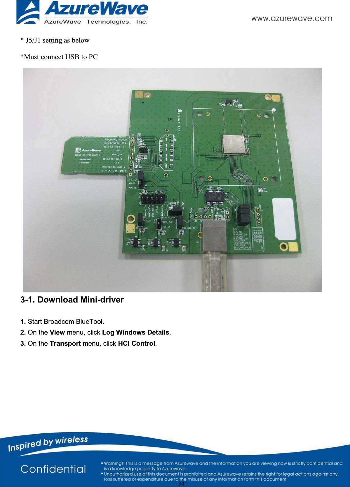
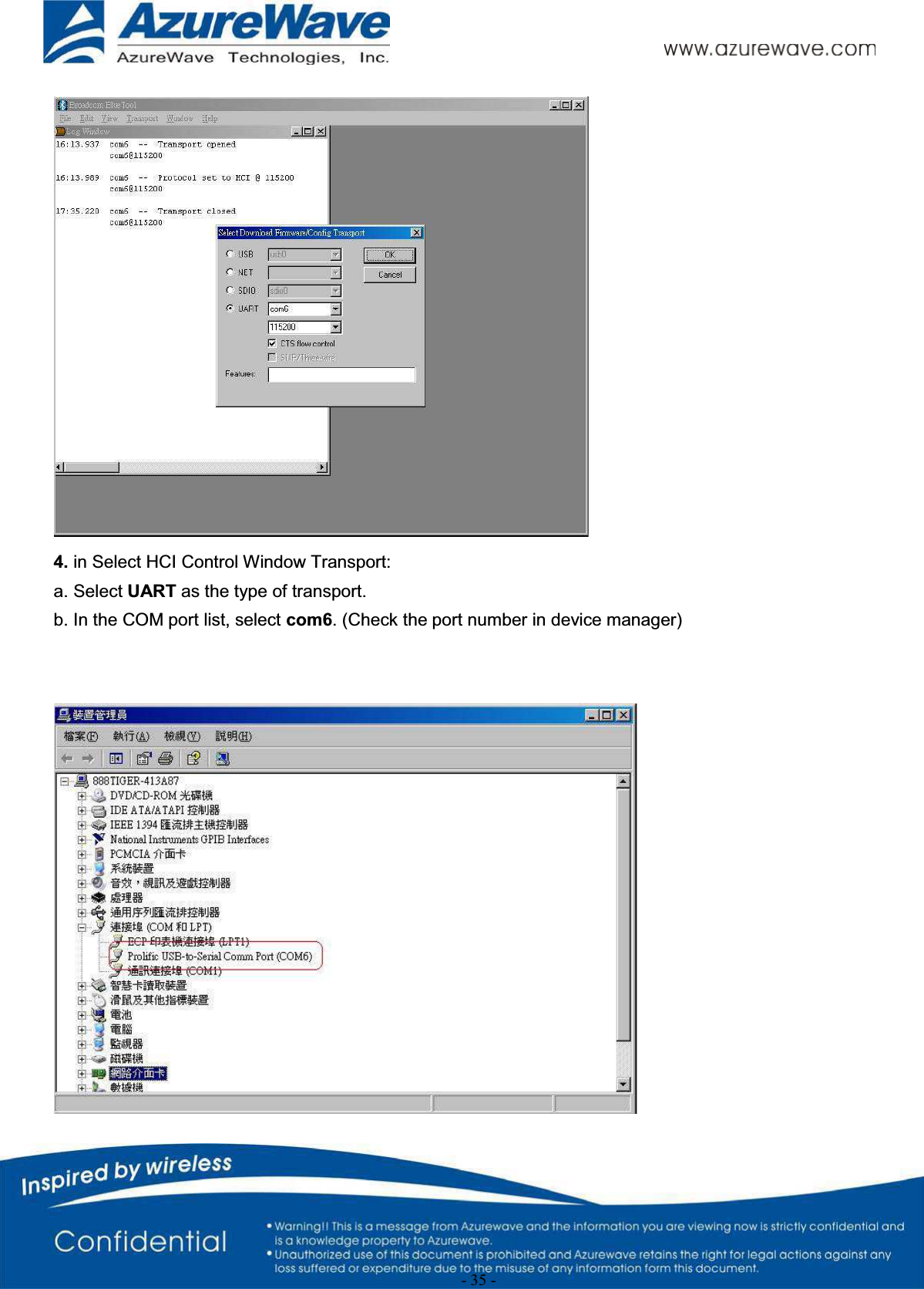
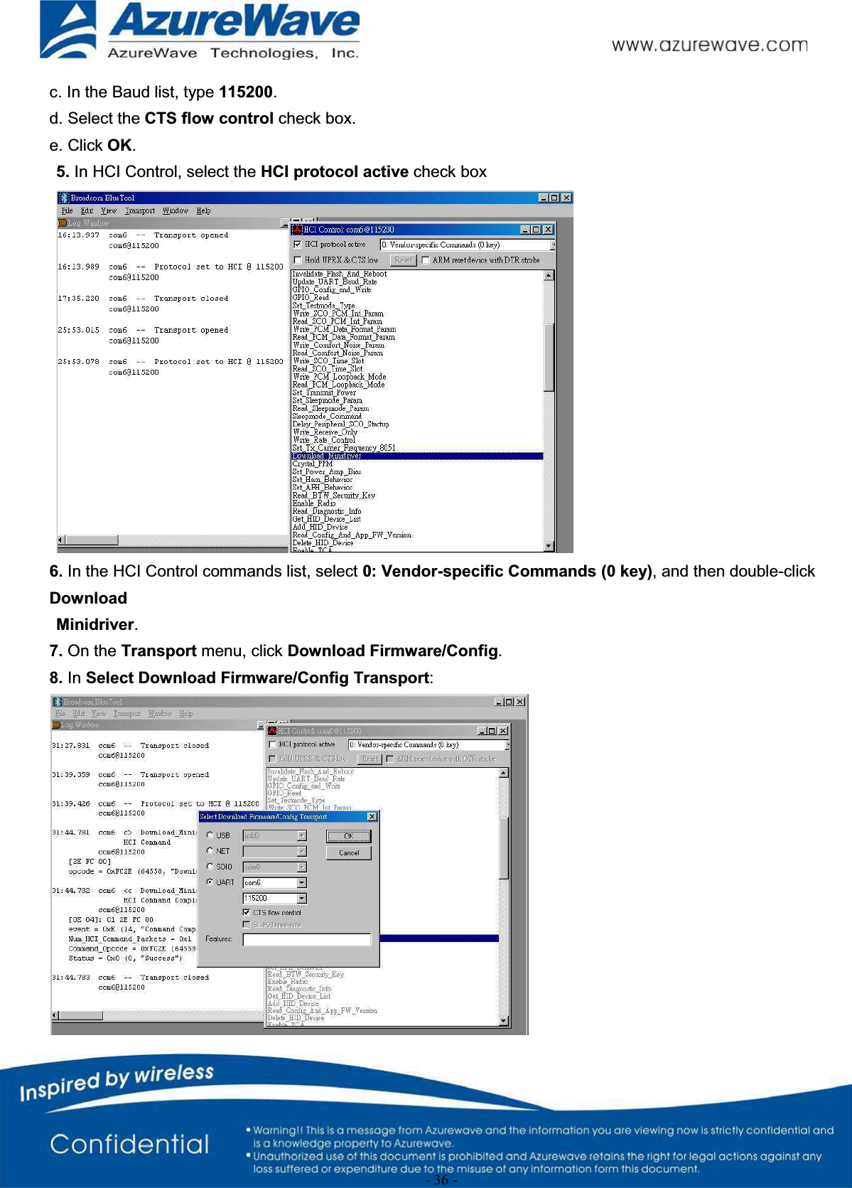
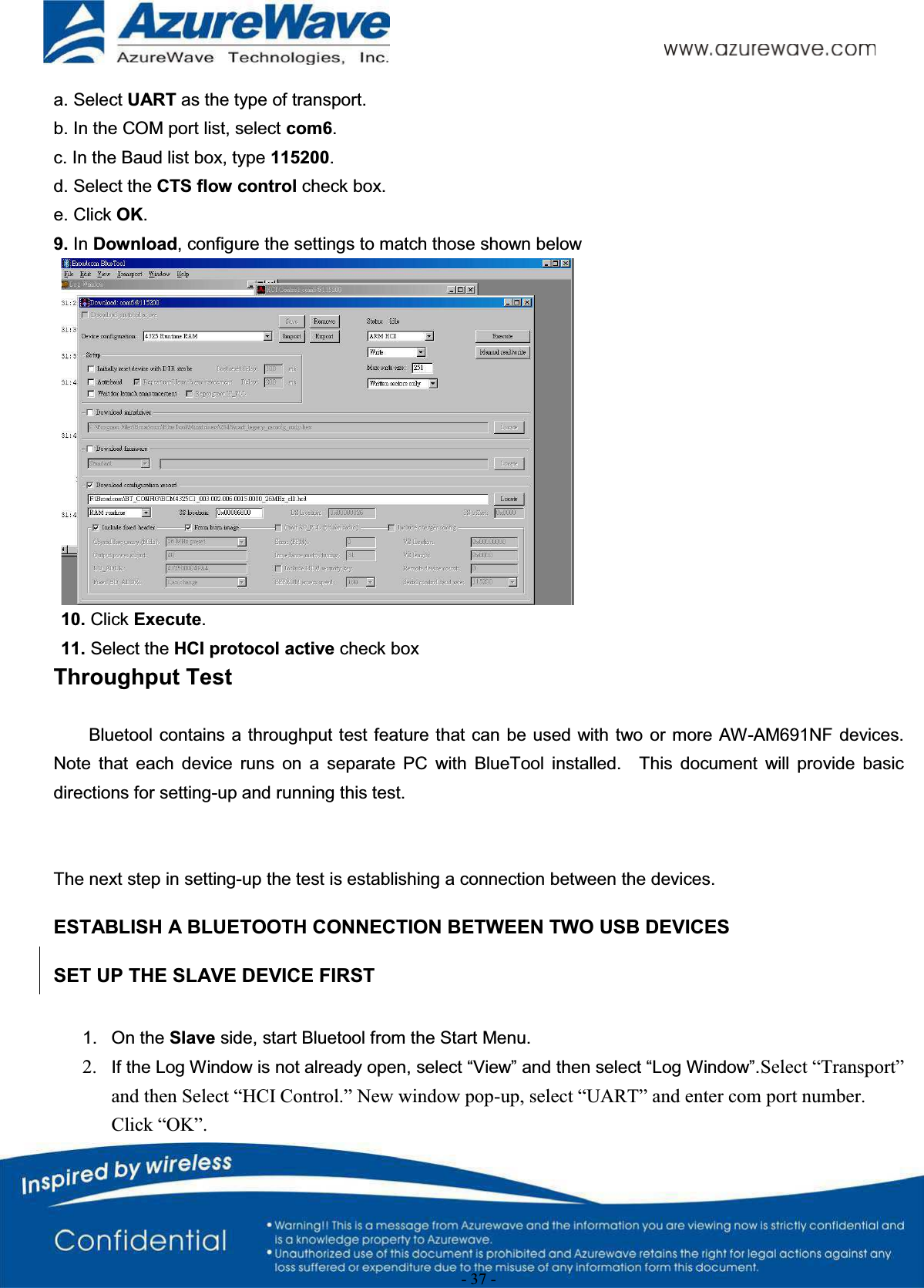
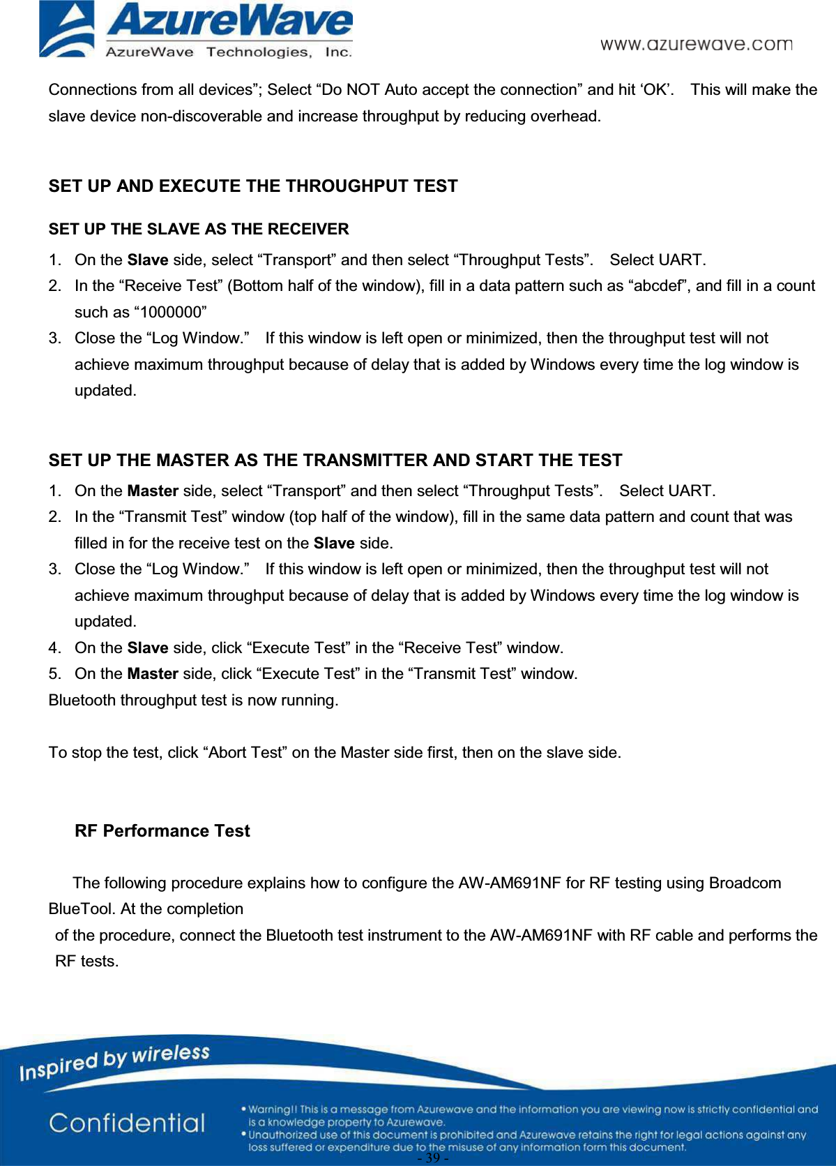
![- 33 -5. The RX PER = [ (Total lost packets at the receiver) / (Total sent packets from the Signal Generator) ] x 100%.Thus, PER =100% - [(pktengrxducast numbers after sequence play) – (pktengrxducast numbers before sequence play)] / (Total sent packets from the signal Generator) x 100%.A simple PER calculation tool (fer.exe) can help you do the job:NOTE: The fer.exe must be located with wl.exe in the same directory.EUT plug-out./wl downrmmod dhd 3. Bluetooth Basic Test](https://usermanual.wiki/AzureWave-Technologies/AM691NF.User-Manual-pdf/User-Guide-2075732-Page-33.png)