AzureWave Technologies CM2XXNF IEEE 802.11 a/b/g/n/ac Wireless LAN and Bluetooth M.2 Combo Module User Manual AW CM195NF user guide ver0 1

AzureWave Technologies, Inc. IEEE 802.11 a/b/g/n/ac Wireless LAN and Bluetooth M.2 Combo Module AW CM195NF user guide ver0 1

User Manual (AW-CM195NF)_rev.pdf
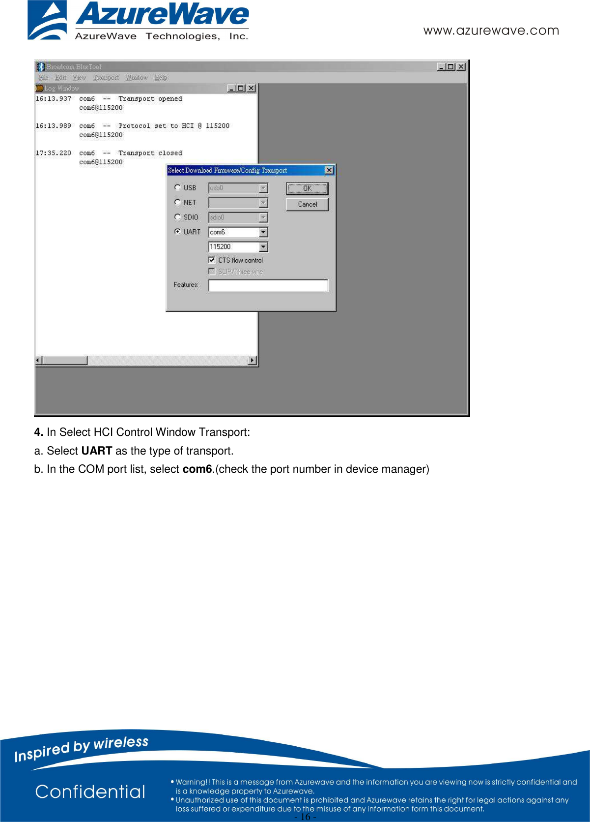
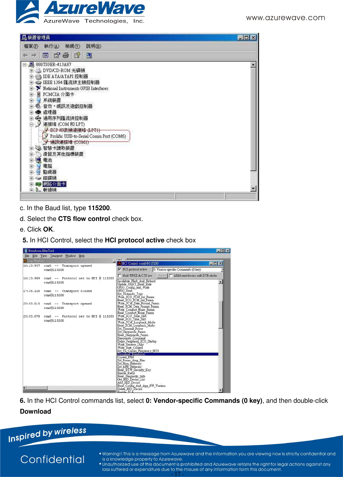
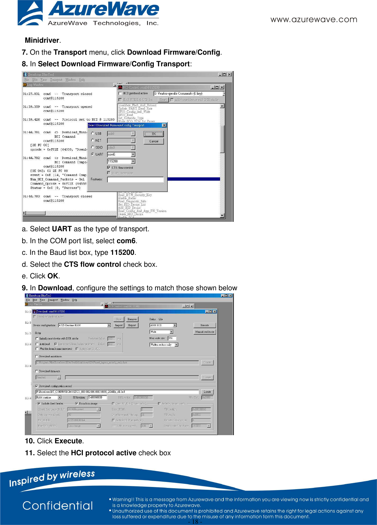
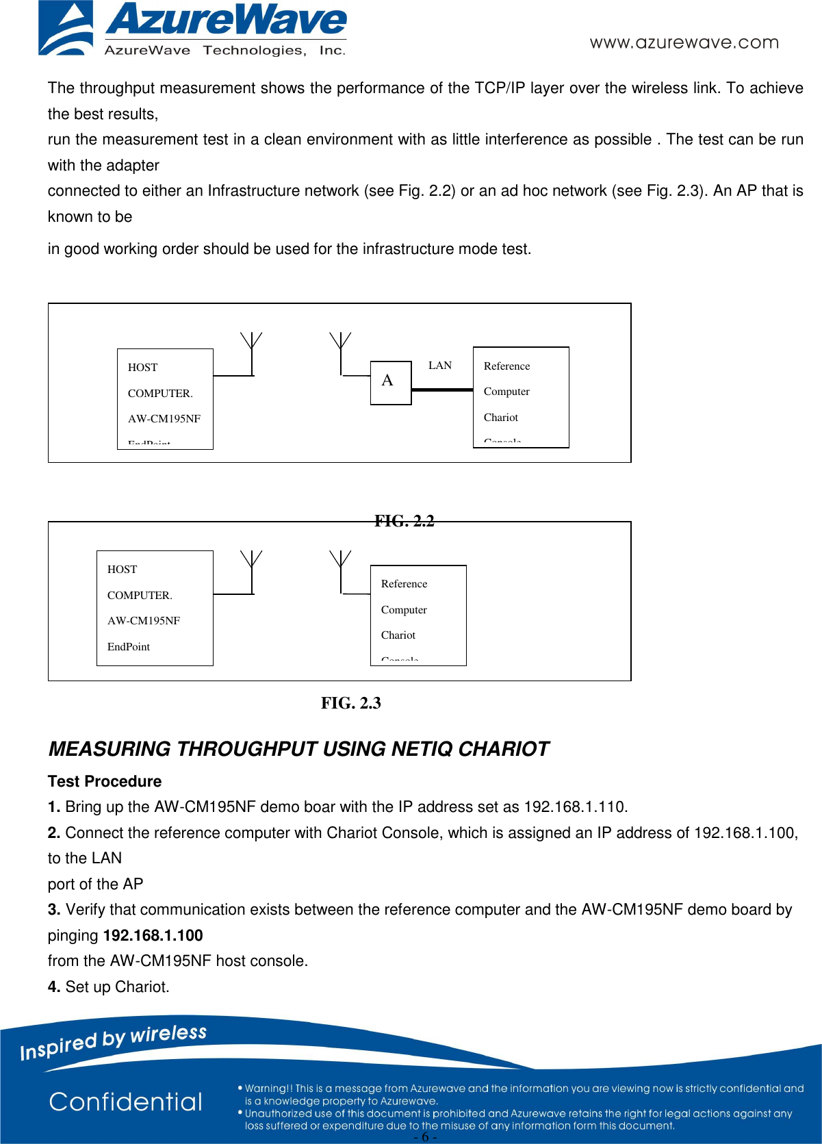
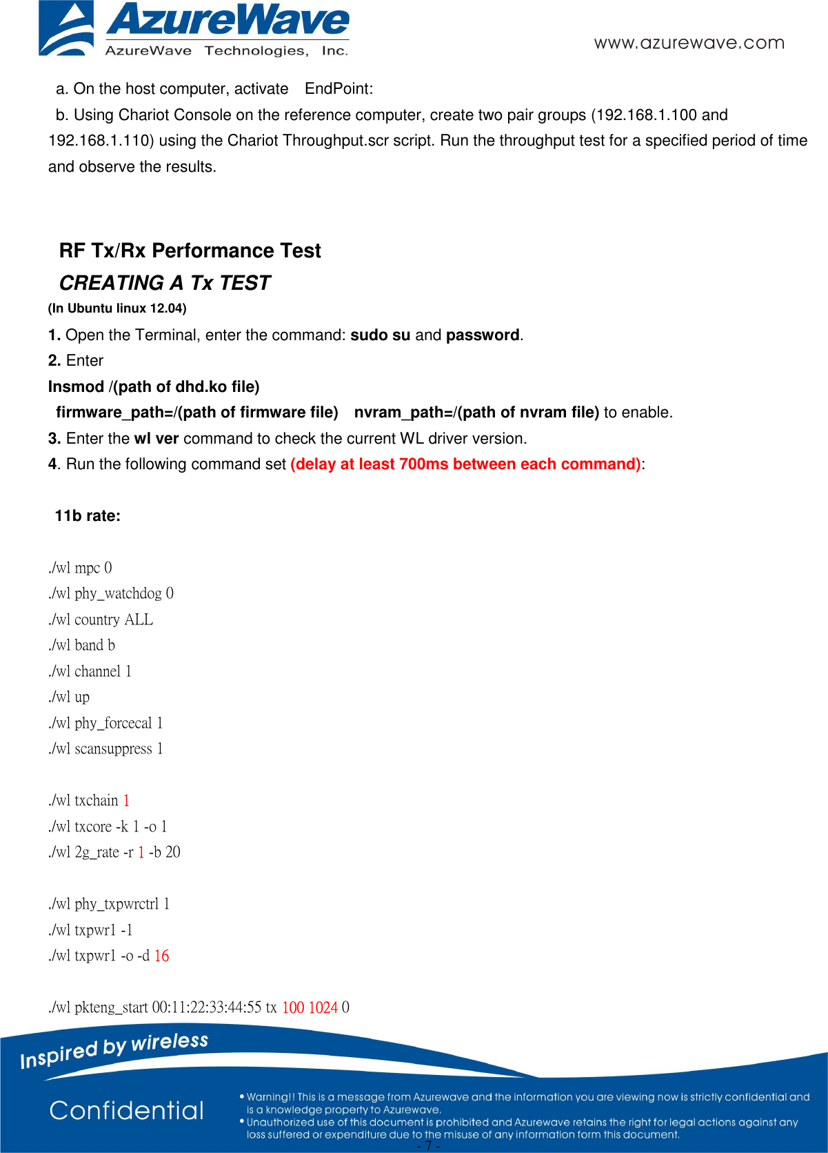
 - 1 -   AW-CM195NF IEEE 802.11 a/b/g/n/ac Wireless LAN and Bluetooth M.2 Combo Module  User Guide    Document release  Date  Modification  Initials  Approved Version 0.1 2015/02/16 Initial Version  Stanley Wang Chihhao Liao
 - 2 -
 - 3 - Contents  1. WLAN Basic Test   Driver Installation   Throughput Test   RF Tx/Rx Performance Test  2. Bluetooth Basic Test   Download Mini-driver   Throughput Test   RF Performance Test  3. Known Limitation/Issues     1. WLAN Basic Test **Must connect USB to PC   Driver Installation DRIVER INSTALLATION (IN LINUX) •First prepare the Broadcom’s linux package, and put it in the “home”folder. •Open the Terminal, enter the command: sudo su and password.
 - 4 - •Enter cd /home/username/ DHD_REL_1_141_65_1_Linux/src/dhd/linux •Enter make dhd-cdc-sdmmc-gpl to generate the dhd.ko file in /home/username/ DHD_REL_1_141_65_1_Linux /src/dhd/linux/dhd-cdc-sdmmc-gpl-2.6.32-21-generic •Enter   Insmod /(path of dhd.ko file)   firmware_path=/(path of firmware file)    nvram_path=/(path of nvram file) to enable. •Enter rmmod dhd to disable • Throughput Test  CONNECTING TO WIRELESS NETWORKS The examples in the following sections illustrate how to connect to both infrastructure and ad hoc networks, including infrastructure networks that use no security, WEP security, and WPA/PSK and WPS2/PSK security.  SCANNING FOR WIRELESS NETWORKS To force the dongle to scan • Run wl scan. To force the dongle to return the results of the scan • Run wl scanresults. Example results returned when an AP is found: • SSID: “Eval4325” • Mode: Managed: RSSI: -48 dBm noise: -105 dBm Channel: 1 • BSSID: 00:10:18:90:2E:C1 Capability: ESS ShortSlot • Supported Rates: [ 1(b) 2(b) 5.5(b) 11(b) 18 24 36 54 6 9 12 48 ] Example results returned when an ad hoc network is found: • SSID: “ADHOC#1” • Mode: Ad Hoc RSSI: -41 dBm noise: -105 dBm Channel: 1 • BSSID: B2:51:28:6B:3C:A1 Capability: IBSS • Supported Rates: [ 1(b) 2(b) 5.5(b) 11(b) ]  CONNECTING TO AN INFRASTRUCTURE NETWORK WITH NO SECURITY (AP CONNECTION) To connect to the network through an AP with SSID = Eval4325 Run wl join Eval4325.  CONNECTING TO AN INFRASTRUCTURE NETWORK WITH WEP SECURITY
 - 5 - To connect to the network that uses 12345 as the network key • Run wl join Eval4325 key 12345.  CONNECTING TO AN INFRASTRUCTURE NETWORK WITH WPA-PSK/WPA2-PSK SECURITY To specify TKIP or AES as the data encryption method • Run wl wsec 3/7. To enable the supplicant • Run wl sup_wpa 1. To specify the PSK passphrase (network key) to use • Run wl set_psk $passphrase. To connect to a network that uses WPA-PSK security • Run wl join Eval4325 imode bss amode wpapsk. To connect to a network that uses WPA2-PSK security • Run wl join Eval4325 imode bss amode wpa2psk.  CONNECTING TO AN AD HOC NETWORK USING CHANNEL 1 To set the channel to channel 1 • Run wl channel 1. To connect to the ad hoc network with SSID = 4325-ADHOC • Run wl join 4325-ADHOC imode ibss.    MANAGING POWER CONSUMPTION To disable Power Save (PS) mode (default) • Run wl PM 0. To enable legacy IEEE 802.11 Power Save (PS) mode • Run wl PM 1. To enable Fast IEEE 802.11 Power Save mode • Run wl PM 2. Note: • The STA automatically transitions to Legacy PS mode when no data is being sent or received. • The STA automatically disables PS mode when data is being sent or received.  MEASURING WLAN THROUGHPUT
 - 6 - The throughput measurement shows the performance of the TCP/IP layer over the wireless link. To achieve the best results, run the measurement test in a clean environment with as little interference as possible . The test can be run with the adapter connected to either an Infrastructure network (see Fig. 2.2) or an ad hoc network (see Fig. 2.3). An AP that is known to be in good working order should be used for the infrastructure mode test.      MEASURING THROUGHPUT USING NETIQ CHARIOT Test Procedure 1. Bring up the AW-CM195NF demo boar with the IP address set as 192.168.1.110. 2. Connect the reference computer with Chariot Console, which is assigned an IP address of 192.168.1.100, to the LAN port of the AP 3. Verify that communication exists between the reference computer and the AW-CM195NF demo board by pinging 192.168.1.100 from the AW-CM195NF host console. 4. Set up Chariot. HOST COMPUTER. AW-CM195NF EndPoint Reference Computer Chariot Console HOST COMPUTER. AW-CM195NF EndPoint AP LAN Reference Computer Chariot Console FIG. 2.2 FIG. 2.3
 - 7 - a. On the host computer, activate    EndPoint: b. Using Chariot Console on the reference computer, create two pair groups (192.168.1.100 and 192.168.1.110) using the Chariot Throughput.scr script. Run the throughput test for a specified period of time and observe the results.   RF Tx/Rx Performance Test CREATING A Tx TEST (In Ubuntu linux 12.04) 1. Open the Terminal, enter the command: sudo su and password. 2. Enter   Insmod /(path of dhd.ko file)   firmware_path=/(path of firmware file)    nvram_path=/(path of nvram file) to enable. 3. Enter the wl ver command to check the current WL driver version. 4. Run the following command set (delay at least 700ms between each command):  11b rate:  ./wl mpc 0 ./wl phy_watchdog 0 ./wl country ALL ./wl band b ./wl channel 1 ./wl up ./wl phy_forcecal 1 ./wl scansuppress 1  ./wl txchain 1 ./wl txcore -k 1 -o 1 ./wl 2g_rate -r 1 -b 20    ./wl phy_txpwrctrl 1 ./wl txpwr1 -1 ./wl txpwr1 -o -d 16  ./wl pkteng_start 00:11:22:33:44:55 tx 100 1024 0
 - 8 -    This will send continuous Tx Packets with 100 us packet interval,1024 byte packet length. Data rate =1Mbps ,Channel=1 and output power =16dBm.   11g rate:  ./wl mpc 0 ./wl phy_watchdog 0 ./wl country ALL ./wl band b ./wl channel 1 ./wl up ./wl phy_forcecal 1 ./wl scansuppress 1  ./wl txchain 1   ./wl txcore -k 1 -o 1   ./wl 2g_rate -r 54 -b 20    ./wl phy_txpwrctrl 1 ./wl txpwr1 -1 ./wl txpwr1 -o -d 15  ./wl pkteng_start 00:11:22:33:44:55 tx 100 1024 0  This will send continuous Tx Packets with 100 us packet interval,1024 byte packet length. Data rate =54Mbps ,Channel=1 and output power =15dBm.      2.4G 11n 20 SISO rate:
 - 9 -  ./wl mpc 0 ./wl phy_watchdog 0 ./wl country ALL ./wl band b   ./wl chanspec 1/20   ./wl up ./wl phy_forcecal 1 ./wl scansuppress 1   ./wl txchain1   ./wl txcore -s 1 -c 1   ./wl 2g_rate -h 7 -b 20  ./wl phy_txpwrctrl 1  ./wl txpwr1 -o -d 14  ./wl pkteng_start 00:11:22:33:44:55 tx 100 1024 0  This will send continuous Tx Packets with 100 us packet interval,1024 byte packet length. Data rate =MCS7, Bandwidth=20Mhz, Channel=1 and output power =14dBm.  2.4G 11n 40 SISO rate:  ./wl down ./wl PM 0 ./wl mimo_bw_cap 1   ./wl mimo_txbw 4   ./wl mpc 0 ./wl up ./wl country ALL ./wl band b ./wl txchain 2 ./wl rxchain 2
 - 10 - ./wl chanspec 3/40l ./wl nrate -m 7 ./wl up ./wl scansuppress 1 ./wl sgi_tx 0   ./wl nrate -m 7   ./wl txpwr1 -o -q 48       ./wl phy_forcecal 1 ./wl pkteng_start 10:20:30:40:50:60 tx 100 1500 0  This will send continuous Tx Packets with 100 us packet interval,1024 byte packet length. Data rate = MCS7 ,Bandwidth=40Mhz, Channel=3 and output power =12dBm.  11a rate:  ./wl mpc 0 ./wl phy_watchdog 0 ./wl country ALL ./wl band a   ./wl channel 36 ./wl up ./wl phy_forcecal 1 ./wl scansuppress 1 ./wl txchain 1 ./wl txcore -o 1 ./wl 5g_rate -r 54 -b 20 ./wl phy_txpwrctrl 1 ./wl txpwr1 -o -d 14 ./wl pkteng_start 00:11:22:33:44:55 tx 100 1024 0  This will send continuous Tx Packets with 100 us packet interval,1024 byte packet length. Data rate =54Mbps ,Channel=36 and output power =14dBm.  5G 11n 20 SISO rate:  ./wl mpc 0
 - 11 - ./wl phy_watchdog 0 ./wl country ALL ./wl band a   ./wl chanspec 36/20   ./wl up ./wl phy_forcecal 1 ./wl scansuppress 1 ./wl txchain 1   ./wl txcore -s 1 -c 1   ./wl 5g_rate -h 7 -b 20 ./wl phy_txpwrctrl 1 ./wl txpwr1 -o -d 12 ./wl pkteng_start 00:11:22:33:44:55 tx 100 1024 0  This will send continuous Tx Packets with 100 us packet interval,1024 byte packet length. Data rate = MCS7 ,Bandwidth=20Mhz, Channel=36 and output power =12dBm.  5G 11n 40 SISO rate:  ./wl mpc 0 ./wl phy_watchdog 0 ./wl country ALL ./wl band a   ./wl chanspec 38/40   ./wl up ./wl phy_forcecal 1 ./wl scansuppress 1 ./wl txchain 1   ./wl txcore -s 1 -c 1   ./wl 5g_rate -h 7 -b 40 ./wl phy_txpwrctrl 1 ./wl txpwr1 -o -d 12 ./wl pkteng_start 00:11:22:33:44:55 tx 100 1024 0    This will send continuous Tx Packets with 100 us packet interval,1024 byte packet length. Data rate = MCS7 ,Bandwidth=40Mhz, Channel=38 and output power =12dBm.
 - 12 -  CREATING A Rx TEST  (In Ubuntu linux 12.04) 1. Open the Terminal, enter the command: sudo su and password. 2. Enter   Insmod /(path of dhd.ko file) firmware_path=/(path of firmware file) nvram_path=/(path of nvram file)   to enable. 3. Enter the wl ver command to check the current WL driver version. 4. Run the following command set    11b/g rate:  ./wl mpc 0 ./wl phy_watchdog 0 ./wl country ALL ./wl band b   ./wl channel 7 ./wl up ./wl phy_forcecal 1 ./wl scansuppress 1 ./wl rxchain 1 ./wl reset_cnts ./wl counters  This will enter Channel 7 receive mode.    2.4G 11n 20 SISO rate:  ./wl mpc 0 ./wl phy_watchdog 0 ./wl country ALL ./wl band b ./wl chanspec 1/20
 - 13 - ./wl up ./wl phy_forcecal 1 ./wl scansuppress 1 ./wl rxchain 1   ./wl reset_cnts ./wl counters   This will enter Channel 1, bandwidth=20Mhz receive mode.   2.4G 11n 40 SISO rate:  ./wl pkteng_stop rx ./wl down ./wl mpc 0 ./wl country ALL ./wl up ./wl phy_watchdog 0 ./wl scansuppress 1 ./wl band b ./wl down ./wl mimo_bw_cap 1 ./wl mimo_txbw 4 ./wl up ./wl chanspec -c 6 -b 2 -w 40 -s 0 ./wl 2g_rate ./wl txchain 1 ./wl rxchain 1 ./wl phy_forcecal 1 ./wl pkteng_start 00:11:22:33:44:55 rxwithack ./wl counters ./wl reset_cnts  This will enter Channel 6, bandwidth=40Mhz receive mode.  11a rate:
 - 14 - ./wl mpc 0 ./wl phy_watchdog 0 ./wl country ALL ./wl band a ./wl channel 36 ./wl up ./wl phy_forcecal 1 ./wl scansuppress 1 ./wl rxchain 1 ./wl reset_cnts   ./wl counters    This will enter Channel 36 receive mode.  5G 11n 20 SISO rate:  ./wl mpc 0 ./wl phy_watchdog 0 ./wl country ALL ./wl band a ./wl chanspec 36/20   ./wl up ./wl phy_forcecal 1 ./wl scansuppress 1 ./wl rxchain 1   ./wl reset_cnts ./wl counters    This will enter Channel 36, bandwidth=20Mhz receive mode.   5G 11n 40 SISO rate:  ./wl mpc 0 ./wl phy_watchdog 0 ./wl country ALL
 - 15 - ./wl band a ./wl chanspec 38/40   ./wl mimo_txbw 4 ./wl up ./wl phy_forcecal 1 ./wl scansuppress 1 ./wl rxchain 1 ./wl reset_cnts ./wl counters    This will enter MCS7 HT40, Channel 38 receive mode.  ※.The default MAC address is 001122334455. Packets sent from Signal Generator must have the same MAC address as the DUT’s MAC address (Runtime mac address can be overrode by using wl cur_etheraddr xx:xx:xx:xx:xx:xx .  ※. Use “./wl counters” and find the received frame numbers in “rxdfrmocast”. ※. The RX PER = [ (Total lost packets at the receiver) / (Total sent packets from the Signal Generator) ] x 100%. Thus, PER =100% - [(rxdfrmocast numbers after sequence play) – (rxdfrmocast numbers before sequence play)] / (Total sent packets from the signal Generator) x 100%. .    2. Bluetooth Basic Test *Must connect USB to PC  Download Mini-driver  1. Start Broadcom BlueTool. 2. On the View menu, click Log Windows Details. 3. On the Transport menu, click HCI Control.
 - 16 -  4. In Select HCI Control Window Transport: a. Select UART as the type of transport. b. In the COM port list, select com6.(check the port number in device manager)
 - 17 -  c. In the Baud list, type 115200. d. Select the CTS flow control check box. e. Click OK. 5. In HCI Control, select the HCI protocol active check box  6. In the HCI Control commands list, select 0: Vendor-specific Commands (0 key), and then double-click Download
 - 18 - Minidriver. 7. On the Transport menu, click Download Firmware/Config. 8. In Select Download Firmware/Config Transport:  a. Select UART as the type of transport. b. In the COM port list, select com6. c. In the Baud list box, type 115200. d. Select the CTS flow control check box. e. Click OK. 9. In Download, configure the settings to match those shown below  10. Click Execute.   11. Select the HCI protocol active check box
 - 19 - Throughput Test  Bluetool contains a throughput test feature that can be used with two or more AW-CM195NF devices.   Note  that each device runs on a separate  PC with BlueTool installed.    This  document  will provide basic directions for setting-up and running this test.   The next step in setting-up the test is establishing a connection between the devices. ESTABLISH A BLUETOOTH CONNECTION BETWEEN TWO USB DEVICES SET UP THE SLAVE DEVICE FIRST  1.  On the Slave side, start Bluetool from the Start Menu. 2. If the Log Window is not already open, select “View” and then select “Log Window”.Select “Transport” and then Select “HCI Control.” New window pop-up, select “UART” and enter com port number. Click “OK”. 3.  Download mini driver (see 3.1) 4.  In the “HCI Control” window, select “7.3 Host Controller & Baseband Commands”    (Note: may be 4.3, depending on version) 5.  Double Click the “Write Scan Enable” entry 6.  Select “Inquiry and Page Scan Enabled” and click “OK” 7.  Double Click “Set Event Filter” 8.  Select “Connection Setup” 9.  Select “Allow Connections from all devices” 10. Select “Do Auto accept the connection with role switch disabled” 11. Click “OK” 12. In the “HCI Control” window, select “0 Vendor-specific commands”. 13. Double Click the “Write_BD_ADDR” command 14. Enter 001122334455 15. In the “HCI Control” window,select”0 Vendor-specific commands”. Double Click ”Update UART Baud Rate”. Select 3000000 then click OK.
 - 20 - SET UP THE MASTER DEVICE, AND CREATE THE CONNECTION 1.  On the Master side, start Bluetool. 2.  Open the log window, if not already open, and open the UART HCI Transport. 3.  Download mini driver (see 3.1) 4.  In the “HCI Control” window, select “7.1 Link Control Commands”    (Note: may be 4.5 depending on version) 5.  Double Click “Create Connection” and put BD address of the slave device into the BDADDR box.   Click “OK” 6.  In the “HCI Control” window,select”0 Vendor-specific commands”. Double Click ”Update UART Baud Rate”. Select 3000000 then click OK.  A connection should establish now.    This can be verified by looking in the log windows for both devices, which should now contain Connection Complete events with “Success” in the status field.      NOTE: once the connection has been established, Inquiry and Page Scan can be disabled.    Also, go to: “7.3 Host Controller & Baseband Commands” →→ “Set Event Filter”.    Select “Connection Setup”; Select “Allow Connections from all devices”; Select “Do NOT Auto accept the connection” and hit ‘OK’.    This will make the slave device non-discoverable and increase throughput by reducing overhead.        SET UP AND EXECUTE THE THROUGHPUT TEST SET UP THE SLAVE AS THE RECEIVER 1.  On the Slave side, select “Transport” and then select “Throughput Tests”.    Select UART. 2.  In the “Receive Test” (Bottom half of the window), fill in a data pattern such as “abcdef”, and fill in a count such as “1000000” 3.  Close the “Log Window.”    If this window is left open or minimized, then the throughput test will not achieve maximum throughput because of delay that is added by Windows every time the log window is updated.  SET UP THE MASTER AS THE TRANSMITTER AND START THE TEST 1.  On the Master side, select “Transport” and then select “Throughput Tests”.    Select UART. 2.  In the “Transmit Test” window (top half of the window), fill in the same data pattern and count that was filled in for the receive test on the Slave side.
 - 21 - 3.  Close the “Log Window.”    If this window is left open or minimized, then the throughput test will not achieve maximum throughput because of delay that is added by Windows every time the log window is updated. 4.  On the Slave side, click “Execute Test” in the “Receive Test” window. 5.  On the Master side, click “Execute Test” in the “Transmit Test” window. Bluetooth throughput test is now running.  To stop the test, click “Abort Test” on the Master side first, then on the slave side.     RF Performance Test  The following procedure explains how to configure the AW-CM195NF for RF testing using Broadcom BlueTool. At the completion of the procedure, connect the Bluetooth test instrument to the AW-CM195NF with RF cable and performs the RF tests.   RESETTING THE USB DEVICE To reset the USB device •In HCI Control, in the HCI Control commands list, select 7.3: Host Controller & Baseband Commands (3 key), and then double-click Reset.  READING THE BLUETOOTH DEVICE ADDRESS To read the Bluetooth Device Address • In HCI Control, in the HCI Control commands list, select 7.4: Informational Parameters (4 key), and then double-click Read_BD_ADDR. The Bluetooth Device Address (BD_ADDR) is displayed in the log window. The Bluetooth Device Address might be needed by the Bluetooth tester  SETTING THE EVENT FILTER TO AUTOMATICALLY ALLOW CONNECTION To set the event filter to automatically allow connection 1. In HCI Control, in the HCI Control commands list, select 7.3: Host Controller & Baseband Commands (3 key), and
 - 22 - then double-click Set_Event_Filter. 2. In HCI Command: Set_Event_Filter: a. In the Filter_Type list, select Connection Setup. b. In the Connection_Setup_Filter_Condition_Type list, select Allow Connections from all devices. c. In the Auto_Accept_Flag list, select Do Auto accept the connection with role switch disabled.  ENABLING WRITE SCAN To enable Write Scan 1. In HCI Control, in the HCI Control commands list, select 7.3: Host Controller & Baseband Commands (3 key), and then double-click Write_Scan_Enable. 2. In HCI Command: Write_Scan_Enable, in the Scan_Enable list, select Inquiry and Page Scan enabled.  ENABLING TEST MODE To enable Test Mode • In HCI Control, in the HCI Control commands list, select 7.6: Testing Commands (6 key), and then double-click Enable_Device_Under_Test_Mode. The AW-CM195NF is now ready to receive a connection request from the Bluetooth tester and begin testing specified RF parameters.
 - 23 - 3. Known Limitations * AW-CM195NF 2.4G HT40 RX test only support the firmware Ver. 7.35.102 or newer ones.
  1  Federal Communication Commission Interference Statement  This device complies with Part 15 of the FCC Rules. Operation is subject to the following two conditions: (1) This device may not cause harmful interference, and (2) this device must accept any interference received, including interference that may cause undesired operation.  This equipment has been tested and found to comply with the limits for a Class B digital device, pursuant to Part 15 of the FCC Rules.    These limits are designed to provide reasonable protection against harmful interference in a residential installation. This equipment generates, uses and can radiate radio frequency energy and, if not installed and used in accordance with the instructions, may cause harmful interference to radio communications.    However, there is no guarantee that interference will not occur in a particular installation.    If this equipment does cause harmful interference to radio or television reception, which can be determined by turning the equipment off and on, the user is encouraged to try to correct the interference by one of the following measures:  -  Reorient or relocate the receiving antenna. -  Increase the separation between the equipment and receiver. -  Connect the equipment into an outlet on a circuit different from that to which the receiver is connected. -  Consult the dealer or an experienced radio/TV technician for help.  FCC Caution: Any changes or modifications not expressly approved by the party responsible for compliance could void the user's authority to operate this equipment.  This transmitter must not be co-located or operating in conjunction with any other antenna or transmitter.  Radiation Exposure Statement: This equipment complies with FCC radiation exposure limits set forth for an uncontrolled environment. This equipment should be installed and operated with minimum distance 20cm between the radiator & your body.  This device is intended only for OEM integrators under the following conditions:  The antenna must be installed such that 20 cm is maintained between the antenna and users, and   The transmitter module may not be co-located with any other transmitter or antenna.  As long as 2 conditions above are met, further transmitter test will not be required. However, the OEM integrator is still responsible for testing their end-product for any additional compliance requirements required with this module installed  IMPORTANT NOTE: In the event that these conditions can not be met (for example certain laptop configurations or co-location with another transmitter), then the FCC authorization is no longer considered valid and the FCC ID can not be used on the final product. In these circumstances, the OEM integrator will be responsible for re-evaluating the end product (including the transmitter) and obtaining a separate FCC authorization.  End Product Labeling    This transmitter module is authorized only for use in device where the antenna may be installed such that 20 cm may be maintained between the antenna and users. The final end product must be labeled in a visible area with the following: “Contains FCC ID:TLZ-CM2XXNF ”. The grantee's FCC ID can be used only when all FCC compliance requirements are met.  Manual Information To the End User The OEM integrator has to be aware not to provide information to the end user regarding how to
  2 install or remove this RF module in the user’s manual of the end product which integrates this module. The end user manual shall include all required regulatory information/warning as show in this manual.    Industry Canada statement: This device complies with RSS-210 of the Industry Canada Rules. Operation is subject to the following two conditions: (1) This device may not cause harmful interference, and (2) this device must accept any interference received, including interference that may cause undesired operation. Ce dispositif est conforme à la norme CNR-210 d'Industrie Canada applicable aux appareils radio exempts de licence. Son fonctionnement est sujet aux deux conditions suivantes: (1) le dispositif ne doit pas produire de brouillage préjudiciable, et (2) ce dispositif doit accepter tout brouillage reçu, y compris un brouillage susceptible de provoquer un fonctionnement indésirable.    Radiation Exposure Statement: This equipment complies with IC radiation exposure limits set forth for an uncontrolled environment. This equipment should be installed and operated with minimum distance 20cm between the radiator & your body.  Déclaration d'exposition aux radiations: Cet équipement est conforme aux limites d'exposition aux rayonnements IC établies pour un environnement non contrôlé. Cet équipement doit être installé et utilisé avec un minimum de 20 cm de distance entre la source de rayonnement et votre corps.  This device is intended only for OEM integrators under the following conditions:    1) The antenna must be installed such that 20 cm is maintained between the antenna and users, and  2) The transmitter module may not be co-located with any other transmitter or antenna.  As long as 2 conditions above are met, further transmitter test will not be required. However, the OEM integrator is still responsible for testing their end-product for any additional compliance requirements required with this module installed.  Cet appareil est conçu uniquement pour les intégrateurs OEM dans les conditions suivantes: (Pour utilisation de dispositif module) 1) L'antenne doit être installée de telle sorte qu'une distance de 20 cm est respectée entre l'antenne et les utilisateurs, et   2) Le module émetteur peut ne pas être coïmplanté avec un autre émetteur ou antenne.  Tant que les 2 conditions ci-dessus sont remplies, des essais supplémentaires sur l'émetteur ne seront pas nécessaires. Toutefois, l'intégrateur OEM est toujours responsable des essais sur son produit final pour toutes exigences de conformité supplémentaires requis pour ce module installé.   IMPORTANT NOTE: In the event that these conditions can not be met (for example certain laptop configurations or co-location with another transmitter), then the Canada authorization is no longer considered valid and the IC ID can not be used on the final product. In these circumstances, the OEM integrator will be responsible for re-evaluating the end product (including the transmitter) and obtaining a separate Canada authorization.  NOTE IMPORTANTE: Dans le cas où ces conditions ne peuvent être satisfaites (par exemple pour certaines configurations d'ordinateur portable ou de certaines co-localisation avec un autre émetteur), l'autorisation du Canada n'est plus considéré comme valide et l'ID IC ne peut pas être utilisé sur le
  3 produit final. Dans ces circonstances, l'intégrateur OEM sera chargé de réévaluer le produit final (y compris l'émetteur) et l'obtention d'une autorisation distincte au Canada.  End Product Labeling   This transmitter module is authorized only for use in device where the antenna may be installed such that 20 cm may be maintained between the antenna and users. The final end product must be labeled in a visible area with the following: “Contains IC: 6100A-CM2XXNF”.    Plaque signalétique du produit final Ce module émetteur est autorisé uniquement pour une utilisation dans un dispositif où l'antenne peut être installée de telle sorte qu'une distance de 20cm peut être maintenue entre l'antenne et les utilisateurs. Le produit final doit être étiqueté dans un endroit visible avec l'inscription suivante: "Contient des IC: 6100A-CM2XXNF".  Manual Information To the End User The OEM integrator has to be aware not to provide information to the end user regarding how to install or remove this RF module in the user’s manual of the end product which integrates this module. The end user manual shall include all required regulatory information/warning as show in this manual.  Manuel d'information à l'utilisateur final L'intégrateur OEM doit être conscient de ne pas fournir des informations à l'utilisateur final quant à la façon d'installer ou de supprimer ce module RF dans le manuel de l'utilisateur du produit final qui intègre ce module. Le manuel de l'utilisateur final doit inclure toutes les informations réglementaires requises et avertissements comme indiqué dans ce manuel. Caution : (i) the maximum antenna gain permitted for devices in the bands 5250-5350 MHz and 5470-5725 MHz shall comply with the e.i.r.p. limit; and (ii) the maximum antenna gain permitted for devices in the band 5725-5825 MHz shall comply with the e.i.r.p. limits specified for point-to-point and non point-to-point operation as appropriate. (iii) Users should also be advised that high-power radars are allocated as primary users (i.e. priority users) of the bands 5250-5350 MHz and 5650-5850 MHz and that these radars could cause interference and/or damage to LE-LAN devices. Avertissement: Le guide d’utilisation des dispositifs pour réseaux locaux doit inclure des instructions précises sur les restrictions susmentionnées, notamment : (i) le gain maximal d’antenne permis pour les dispositifs utilisant les bandes 5 250-5 350 MHz et 5 470-5 725 MHz doit se conformer à la limite de p.i.r.e.; (ii) le gain maximal d’antenne permis (pour les dispositifs utilisant la bande 5 725-5 825 MHz) doit se conformer à la limite de p.i.r.e. spécifiée pour l’exploitation point à point et non point à point, selon le cas. (iii) De plus, les utilisateurs devraient aussi être avisés que les utilisateurs de radars de haute puissance sont désignés utilisateurs principaux (c.-à-d., qu’ils ont la priorité) pour les bandes 5 250-5 350 MHz et 5 650-5 850 MHz et que ces radars pourraient causer du brouillage et/ou des dommages aux dispositifs LAN-EL.   低功率電波輻射性電機管理辦法 第十二條 經型式認證合格之低功率射頻電機,非經許可,公司、商號或使用者均不得擅自變更頻率、加大功率或變更原設計之特性及功能。 第十四條 低功率射頻電機之使用不得影響飛航安全及干擾合法通信;經發現有干擾現象時,應立即停用,並改善至無干擾時方得繼續使用。 前項合法通信,指依電信法規定作業之無線電通信。 低功率射頻電機須忍受合法通信或工業、科學及醫療用電波輻射性電機設備之干擾。 在5.25-5.35秭赫頻帶內操作之無線資訊傳輸設備,限於室內使用。
  4  1.  本模組於取得認證後將依規定於模組本體標示審驗合格標籤。 2.  系統廠商應於平台上標示「本產品內含射頻模組: XXXyyyLPDzzzz-x」字樣。

Navigation menu