BAE Systems 81FCGX First InterComm VCA100 model 81FCGX User Manual 07 f57 VCA100usermanual indd
BAE Systems First InterComm VCA100 model 81FCGX 07 f57 VCA100usermanual indd
Contents
- 1. User manual
- 2. Installation guide
User manual
ELECTRONICS & INTEGRATED SOLUTIONS
First InterComm™ system
VCA100 user manual
A29798 September 2008

About BAE Systems
BAE Systems is the premier global
defense and aerospace company,
delivering a full range of products and
services for air, land, and naval forces,
as well as advanced electronics,
information technology solutions,
and customer support services.
With 97,500 employees worldwide,
the company had 2007 sales that
exceeded $31.4 billion.
The information contained in this manual
is the property of BAE Systems and is
intended for the purchaser's use only.
It may not be reproduced without the
express written consent of BAE Systems.

First InterComm™ system VCA100 user manual A29798 September 2008 i
List of illustrations i
List of tables i
Warnings and precautions ii
Welcome to First InterComm system 1
First InterComm system overview 1
The First InterComm system in action 2
Operating the First InterComm system 5
Start-up 5
Vehicle location 5
Signal relay (hopping) 7
Troubleshooting 8
First InterComm system component descriptions 8
The VCA100 unit 8
Power-on-built-in test (PBIT) 9
Mobile radio antennas 9
Wireless antenna 9
Appendix A VCA100 specifications 10
Appendix B Acronyms and abbreviations 11
BAE Systems contact information 12
Companion documentation 12
Table of contents
Figure 1 The First InterComm system in action 2
Figure 2 The incident area network (IAN) expands or contracts as needed 3
Figure 3 The First InterComm system enhanced by the optional
Talk Group software 4
Figure 4 Area geometry or physical features can affect talk range 6
Figure 5 LOS obstructions prevent communications 7
Figure 6 First InterComm system range is extended by "hopping" 7
Figure 7 VCA100 front panel connectors 9
Table 1 VCA100 troubleshooting procedures 8
List of illustrations
List of tables

First InterComm™ system VCA100 user manual A29798 September 2008ii
Compliance — This equipment has
been tested and found to comply
with the limits for a Class B digital
device, pursuant to Part 15 of the FCC
rules. These limits are designed to
provide reasonable protection against
harmful interference in a residential
environment. This equipment generates,
uses, and can radiate radio frequency
energy and, if not installed and used in
accordance with the instructions, may
cause harmful interference to radio
communications. Proper installation
does not guarantee that interference
will not occur in a particular situation.
If this equipment does cause harmful
interference to radio or television
reception (which can be determined
by turning the equipment off and on),
the user is encouraged to correct the
interference by one or more of the
following measures:
– Reorient or relocate the receiving
antenna.
– Increase the separation between the
equipment and affected receiver.
– Connect equipment into an outlet on a
circuit different from that to which the
receiver is connected.
– Consult an experienced radio/TV
technician for help.
Radio frequency (RF) exposure
compliance — The First InterComm
system generates and uses RF energy.
Pursuant to FCC rules for the maximum
permissible RF exposure, the antenna(s)
specified in this manual MUST be
installed so as to provide a separation
distance of at least 18 inches (45 cm)
from all persons. The unit may not
be used to transmit for more than 50
percent of the time (average duty cycle
over a 30-minute period).
Users must not change the antenna
types or their location at the risk of
voiding the conditions of their FCC
license and/or the conditions to which
the product has been certified (consult
your installer in these cases). Changes
or modifications to the equipment may
cause harmful interference unless the
modifications are expressly approved in
the installation manual. The authority to
operate the equipment could be lost if
an unauthorized change or modification
is made.
Warnings and precautions
Federal Communications
Commission (FCC)

First InterComm™ system VCA100 user manual A29798 September 2008 iii
– DC power — Ensure power into the
First InterComm system does not
exceed 24 Vdc.
– Explosive environments — Ensure
the First InterComm system is turned
off before entering a blasting area
or in areas posted “TURN OFF TWO-
WAY RADIO.” Sparks in a potentially
explosive atmosphere can cause an
explosion or fire resulting in bodily
injury or death.
Warnings and precautions (continued)
General precautions
Nearly every electronic device is
susceptible to electromagnetic
interference (EMI) if inadequately
designed, shielded, or otherwise
configured for electromagnetic
compatibility. It may be necessary
to conduct compatibility testing to
determine if any electronic equipment
used in or around vehicles is sensitive to
external RF energy, or if any procedures
are needed to eliminate or mitigate
the potential for interaction between
the First InterComm system and other
equipment or devices.
– Facilities — To avoid EMI or
compatibility conflicts, turn off
the First InterComm system near
any facility where posted notices
so instruct, such as hospitals or
healthcare facilities.
– Vehicles — To avoid possible
interaction between the First
InterComm system and vehicle
electronic control modules (such
as antilock brakes and engine or
transmission controls), the First
InterComm system should be installed
only by a professional installer only.
– Pacemakers — To avoid potential
interference with pacemaker
functions, maintain a minimum
separation of 12 inches between First
InterComm system components (the
VCA100 and associated antennas).
Electromagnetic
interference/compatibility

First InterComm™ system VCA100 user manual A29798 September 2008iv
First InterComm system quick-start procedure
Arrive on scene At the incident scene, position First InterComm system-
equipped vehicles within a maximum of a quarter mile
clear line of sight (LOS) of each other at the incident scene.
Power up Apply power to the First InterComm system with the cab-
mounted switch.
Change channel Switch radio equipment to the tactical channel on
portable radio designated for First InterComm system
interoperability.
Talk Communicate using applicable standard operating
procedures (SOP).

First InterComm™ system VCA100 user manual A29798 September 2008 1
Welcome to First InterComm™ system
provided by the VCA100 and associated
antennas alone.
The U.S. Department of Homeland
Security has designated the First
InterComm system as a Qualified
Anti-Terrorism Technology under the
SAFETY Act. The First InterComm
system supports the National Incident
Management System (NIMS) and is
included in the Memorial Institute for the
Prevention of Terrorism “Responders
Knowledge Base” and the InterAgency
Board's Standard Equipment List and
Approved Equipment List.
The First InterComm system enables
the responding departments to
operate within their SOP. It provides
day-to-day voice interoperability at an
incident scene and provides improved
coordination of on-site first-responder
personnel.
This user manual contains a description
of the First InterComm system and
activation information to maximize its
effectiveness.
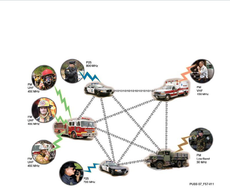
The First InterComm system allows first
responders from different agencies
at an emergency incident to readily
communicate with one another,
even though their radios operate on
different frequencies (i.e., VHF, UHF
or 800 MHz systems, both digital
and analog). The First InterComm
system can accommodate many newer
communication technologies such as
radio systems operating in the 700-MHz
band, and P25-compliant equipment.
Only one vehicle from each on-scene
department is required to have a First
InterComm system installed to enable
linking of dissimilar radio networks.
There is no requirement for special
equipment, stand-alone towers, or other
costly infrastructure.
Talk Group software, an optional
capability included with the First
InterComm system, enables the
incident commander, using a standard
laptop computer with wired or wireless
networking capability, to monitor system
status and control communications. Talk
Group significantly enhances the First
InterComm system, but is not required
for voice interoperability; the latter is
First InterComm system overview
– Compliant with commercial standards
for radio communications and mesh
networks.
– Provides connectivity with civil and
military communications systems.
– Compatible with digital technology,
supporting radio system upgrades.
The First InterComm system consists
of a Vehicle Communications Assembly
(VCA100), a land mobile radio antenna,
and a wireless antenna. Using standard
12-Vdc vehicle power the systems
provides these features:
– No setup time required; voice
interoperability is automatically
available within one minute of arriving
on scene.
– Responders use their existing radios;
multiple radios are not required.
– Responders require minimal training.
– Scalable from routine to large
incidents.
NOTE
– Talk Group software provides
significant capability to the First
InterComm system but is not
required for voice interoperability.
2First InterComm™ system VCA100 user manual A29798 September 2008
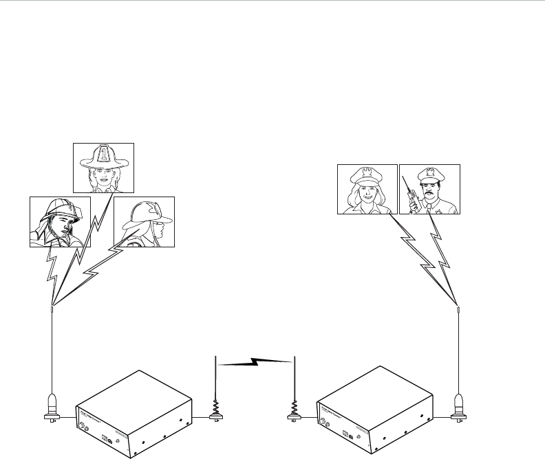
Turning on two or more VCA100 units
establishes an ad hoc wireless mesh
incident area network (IAN). In Figure 1,
the fire department, whose radios
operate at 154.57 MHz, is talking to
the police department, whose radios
operate at 452.95 MHz. When a
portable or mobile radio is keyed up,
its voice transmission is translated
into digital packets that are placed
onto the IAN. Every VCA100 unit on
the First InterComm network receives
these digital packets, which are
translated back into voice transmissions
compatible with each handheld radio
associated with the receiving VCA100.
The First InterComm system in action
Figure 1. The First InterComm system in action
PUBS 07_F57-001
154.57 MHz 452.95 MHz
LMR
GPS
A
NETWORK
POWER
ETHERNET
www.FirstInterComm.com
LMR
GPS
A
NETWORK
POWER
ETHERNET
www.FirstInterComm.com
First InterComm™ system VCA100 user manual A29798 September 2008 3
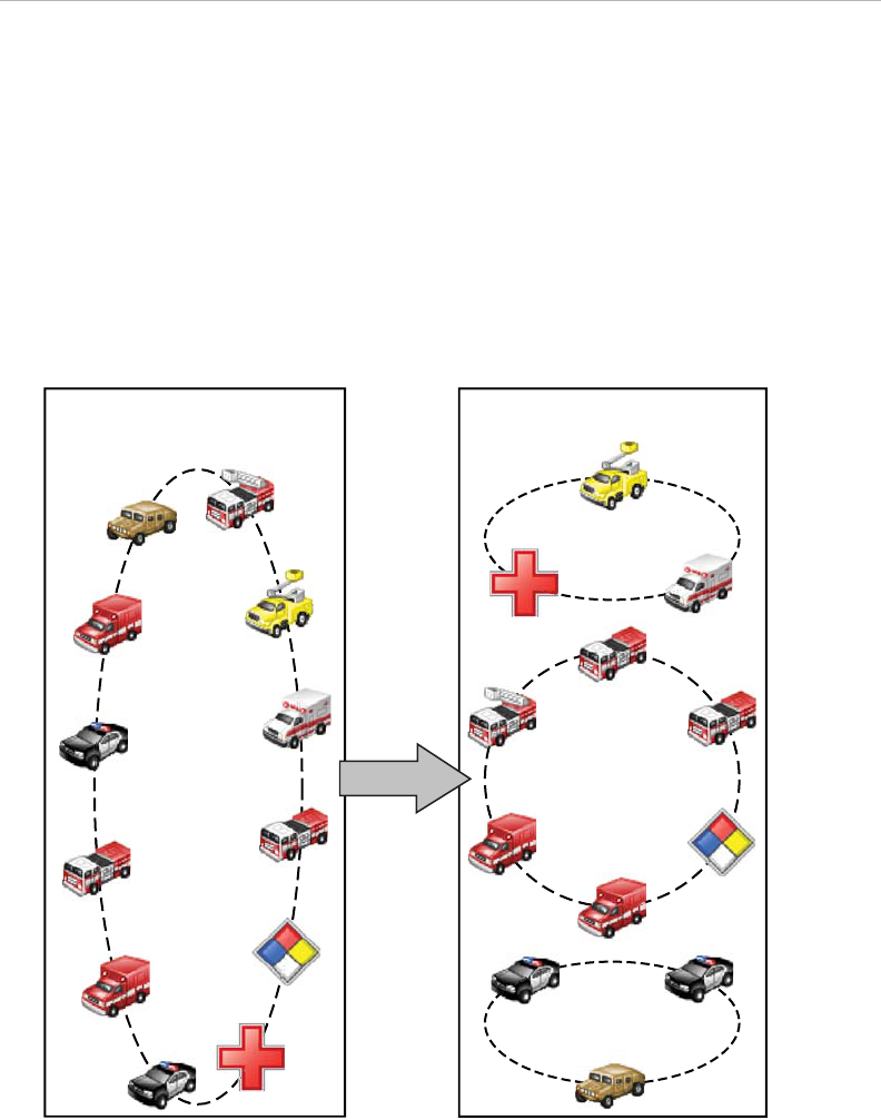
Figure 2. The incident area network expands or contracts as needed
As first responders arrive on scene
and activate their VCA100s, the units
automatically connect to one another.
As the first responders are joined by
other agencies (e.g., public health,
disaster recovery, federal agencies,
National Guard), their VCA100 units
connect to the IAN, thus establishing
cross-jurisdictional communication.
This temporary IAN (Figure 2) exists as
long as VCA100-equipped vehicles are
present and can expand or contract as
first responders enter or leave the area.
First InterComm™ system VCA100 user manual A29798 September 2008
PUBS 07_F57-012
Default:
All responders can talk
With software:
Incident commander assigns who
talks to whom
First
Intercomm™
Talk Group
software
Fire suppression
talk group
Support
talk group
Security
talk group
Initial
incident area network
4
Figure 3. The First InterComm system enhanced by the optional Talk Group software
1Windows XP is a registered trademark of Microsoft Corporation
As numerous first responders are
online, overall coordination is essential.
The incident commander can assume
control of the IAN via any laptop
computer operating with the Windows
XP®1 operating system with Service
Pack 2 and equipped with wired or
wireless networking capability and First
InterComm Talk Group software
(Figure 3). The Talk Group allows the
incident commander to:
– Establish sectors by frequency in
accordance with NIMS.
– Isolate any agency equipped with
First InterComm units (e.g., fire, EMS,
emergency management, public
works, law enforcement) into the
appropriate talk groups, thereby:
– Supporting a chain of command.
– Improving communications
efficiency.
– Increasing emergency responder
safety.
Refer to First InterComm system Talk
Group software user manual
(BAE Systems document No. A29800)
for complete details on Talk Group
software.

First InterComm™ system VCA100 user manual A29798 September 2008 5
Operating the First InterComm system
Vehicle location
Start-up
1. Apply power to the VCA100 with the
cab-mounted switch.
2. Allow approximately one minute for
the unit to initialize and connect to
any other VCA100s in the area.
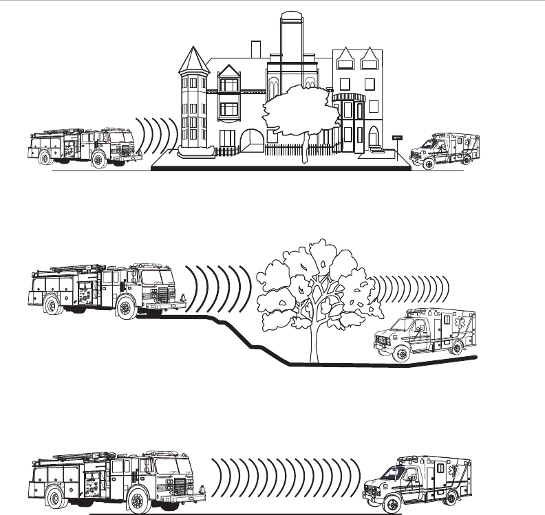
Wireless signals weaken as they
travel away from the transmitter. The
First InterComm system operates up
to a quarter mile between VCA100s,
assuming a clear, unobstructed LOS.
Buildings, hills, vegetation and other
obstructions will reduce range as
shown in Figure 4. Interference from
metallic objects such as large trash
3. Switch radio equipment to the tactical
channel on portable radio designated
for First InterComm system
interoperability.
4. Communicate using the applicable SOP.
receptacles and vehicles can degrade
performance. Whenever possible,
position VCA100-equipped vehicles to
minimize such factors.
RECOMMENDATION
Do not turn on the VCA100 unit until parked at the scene.
First InterComm™ system VCA100 user manual A29798 September 20086
Figure 4. Area geometry or physical features can affect talk range
PUBS 07 F57-006
PUBS 07_F57-007
PUBS 07_F57-008
Heavy signal obstruction
Poorer reception
Optimal: clear line of sight
First InterComm™ system VCA100 user manual A29798 September 2008
PUBS 07_F57-01
0
A
B
C
7
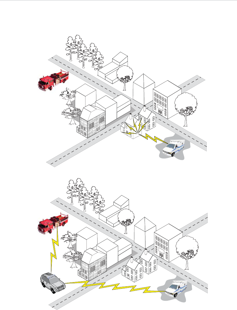
Figure 5 shows a generalized urban
incident site where there is no LOS
between vehicles A and B. Figure
6 showshow positioning vehicle C
enables the First InterComm system to
overcome these obstacles by “hopping”
voice communications (i.e., passing
communications through the units
that do have LOS). Thus, all units can
communicate even though not all have
direct LOS.
Figure 6. First InterComm range is extended by "hopping"
Figure 5. LOS obstructions prevent communications
PUBS 07_F57-009
A
B
Signal relay (hopping)

First InterComm™ system VCA100 user manual A29798 September 20088
Table 1. VCA100 troubleshooting procedures
IMPORTANT
– If the First InterComm system appears to interfere with incident site
operations, immediately turn off every VCA100 unit and Talk Group software in
use and return to normal operating procedures.
– If Talk Group software or laptop computer problems occur, the VCA100 units
will remain in their assigned talk groups. If the laptop or Talk Group software
is not functional and communication is needed among all responders, cycle
power to all VCA100s. This entails turning off the power to the VCA100 and
then repowering.
Troubleshooting
– Land mobile radio antenna matched
to user’s existing radio network
frequencies.
– Remote on/off switch.
– Talk Group software (optional capability).
pre-designated interoperability channel
to monitor or speak to members of other
radio networks at the site. The specific
VCA100 model is based on the radio
frequencies used by the participating
department (see Appendix A).
The First InterComm system consists of:
– VCA100 unit matched to user’s
existing radio network frequencies.
– Vehicle-mounted wireless antenna.
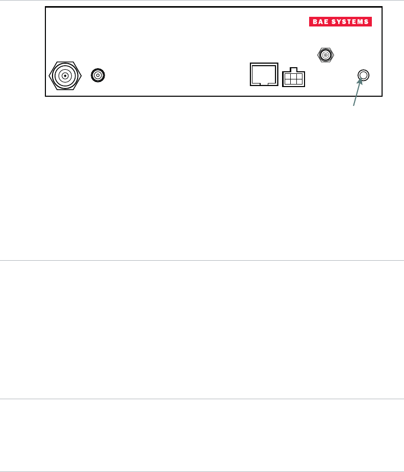
The VCA100 unit (Figure 7) is vehicle-
mounted and has no operator controls
other than a remote power-on switch. Once
the VCA100 is initialized, operations are
transparent to the operator, responders
need only set their radio equipment to the
First InterComm system component descriptions
The VCA100 unit
Problem Action Comments
No
communications
via First
InterComm
systems
1. Verify indicator on power
switch is lit. If not, verify that
fuse is good.
2. Verify the activity indicator on
VCA100 front panel is lit.
3. Verify all communication
devices are using the
designated interoperability
channel.
4. Verify at least two VCA100s
are in the incident area and
power has been applied
to the units for at least 60
seconds.
5. Verify each VCA100 wireless
antenna has clear LOS to
other wireless antennas.
6. Verify distance between
VCA100 wireless antennas
is a quarter mile or less.
1. If the activity indicator
is not easily viewed,
a secondary power
indication is an amber
LED in the lower right
corner of the Ethernet
connector (Figure 7).
2. If the fuse is good,
but there is no power
indication, contact
maintenance personnel.
First InterComm™ system VCA100 user manual A29798 September 2008 9
Power-on built-in test (PBIT)
The activity indicator displays the
progress of the built-in tests that run
during boot up of the VCA100. Once
power is applied, the indicator will light
for approximately 30 seconds, turn off
for approximately 10 seconds, turn
on again and remain on, indicating all
tests passed. If the indicator does not
illuminate the second time, PBIT has
identified an out-of-tolerance condition
Mobile radio antennas
Wireless antenna
This vehicle-mounted antenna matches
the frequency range of its associated
VCA100 unit and must be compatible
with the user’s existing radio network.
This vehicle-mounted antenna covers the
2.4-GHz to 2.5-GHz frequency range and
is compatible with the VCA100.
www.FirstInterComm.com
VCA100
First InterComm™
LMR GPS ETHERNET POWER
NETWORK
A
Activity
Indicator
LMR Two-way radio antenna connection, TNC
GPS Reserved for future implementation
Ethernet Factory use only
Power Nominal 13.6 Vdc and 1.75A max
On/off control is via cab-mounted switch toggle switch
Network Wireless antenna port A, reverse polarity SMA connector
Activity indicator Power on built-in-test indicator light
Figure 7. VCA100 front panel connectors
(e.g., temperature or voltage extremes).
If the VCA100 had been exposed to
temperatures below -20° C or above 60° C
when the symptom appeared, allow
the unit to reach an operating
temperature within this range, cycle
power, and monitor for correct
indications. If the symptoms persist,
a fault is present and maintenance
personnel should be contacted.

First InterComm™ system VCA100 user manual A29798 September 200810
Appendix A
VCA100 specifications
General
VCA100 configurations
Dimensions 2.5” × 8.5” × 8.5” (H x W x D)
Weight 4 pounds
Input voltage 9 to 17 Vdc (13.6 Vdc nominal)
Input current 1.75A maximum (at 13.6V)
Input power connector 6-pin Molex
Frequency Varies with model
Transmit power 5 to 6 watts in LMR band (typical)
Connectors
Network RP-SMA (SMA with male pin)
LMR TNC with receptacle contact
GPS SMA with receptacle contact (future option)
Ethernet RJ-45 (factory use only)
Environmental
Cooling Ambient air, no fan
Temperature -20°C to +60°C (operating)
Humidity Up to 90%
Vibration MIL-STD-810F, Method 514.5, procedure I
Shock MIL-STD-810F, Method 516.5, procedure I
Model Protocol Encryption Band Frequency range
VCA100-L1FCGX FM None VHF, Low-band 29.7 – 37 MHz
VCA100-L2FCGX FM None VHF, Low-band 35 – 50 MHz
VCA100-V1FCGX FM None VHF, High-band 136 – 174 MHz
VCA100-V1PCGX FM/P25 None VHF, High-band 136 – 174 MHz
VCA100-V1PAGX FM/P25 DES/AES VHF, High-band 136 – 174 MHz
VCA100-V1PDGX FM/P25 DES VHF, High-band 136 – 174 MHz
VCA100-U1FCGX FM None UHF 450 – 520 MHz
VCA100-71PCGX FM/P25 None 700 764 – 806 MHz
VCA100-81FCGX FM None 800 806 – 870 MHz
VCA100-81PCGX FM/P25 None 800 806 – 870 MHz
VCA100-81PDGX FM/P25 DES 800 806 – 870 MHz
VCA100-91FCGX FM None 900 896 – 941 MHz

First InterComm™ system VCA100 user manual A29798 September 2008
AEL Authorized equipment list
AES Advanced encryption standard adopted as standard by U.S. government
DC Direct current
DES Data Encryption Standard
DHS Department of Homeland Security
EMI Electromagnetic interference
FCC Federal Communications Commission
FM Frequency modulation
GPS Global Positioning System
IAN Incident area network
LED Light-emitting diode
LOS Line of sight
MIL-STD Military standard
NIMS National Incident Management System
P25 Project 25 (encryption protocol for digital communications)
RF Radio frequency
SEL Standardized equipment list
SMA Subminiature version A (RF connector)
SOP Standard operating procedures
TNC Threaded Neill-Concelman (RF connector)
UHF Ultra high frequency
VCA Vehicle communications assembly
VHF Very high frequency
VoIP Voice-over-Internet protocol
Appendix B
Acronyms and abbreviations
11

First InterComm™ system VCA100 user manual A29798 September 2008
Telephone support 603-459-5643
E-mail firstintercomm.eis@baesystems.com
www.firstintercomm.com
BAE Systems contact information
12
Companion documentation
First InterComm™ system Talk Group software user manual, document No. A29800,
July 2008

PUBS-07-F57-VCA100usermanual
For more information, contact:
BAE Systems
P. O. Box 868, PTP01-2218
Nashua, New Hampshire 03061-0868
Telephone 603-885-9605
Fax 603-885-3563
www.firstintercomm.com
©2008 BAE Systems. All rights reserved.
Cleared for open publication 07/08
We Protect Those Who Protect Us®