BAE Systems 81FCGX First InterComm VCA100 model 81FCGX User Manual Installation guide
BAE Systems First InterComm VCA100 model 81FCGX Installation guide
Contents
- 1. User manual
- 2. Installation guide
Installation guide
A29799 rev A
May 2008
PROPRIETARY INFORMATION: This document contains trade secrets and commercial or financial information that is the property of BAE
Systems Electronics and Integrated Solutions (E&IS). Further dissemination or disclosure of this information is strictly prohibited without
the written permission of BAE Systems.
First InterComm™ System
VCA100
Installation Guide
** NOTE: if time permits this manual will be laid out in 8x10 format w/
spiral binder by the Media dept and made to look similar to other FISC
manuals at the completion of stake holder review. Page breaks and
column formatting will be different. Graphics will be cleaned up.
Intended audience is sub-contracted 2-way shops that have signed a
NDA and have a SOW.
PROPRIETARY INFORMATION: This document contains trade secrets and commercial or financial information that is the property of BAE
Systems Electronics and Integrated Solutions (E&IS). Further dissemination or disclosure of this information is strictly prohibited without
the written permission of BAE Systems.
© 2007, BAE Systems Information and Electronic Systems Integration Inc.. All rights
reserved
The information contained in this manual is the property of BAE Systems and is
intended for the purchaser’s use only. It may not be reproduced without the express
written consent of BAE Systems.

First InterComm
™
System VCA100 Installation Guide
A29799 rev A Page 1
PROPRIETARY INFORMATION: This document contains trade secrets and commercial or financial information that is the property of BAE
Systems Electronics and Integrated Solutions (E&IS). Further dissemination or disclosure of this information is strictly prohibited without
the written permission of BAE Systems.
Table of Contents
List of Illustrations........................................................................................................ 2
List of Tables................................................................................................................. 2
Warnings and Precautions........................................................................................... 3
1.0 Introduction......................................................................................................... 6
2.0 First InterComm™ System Description........................................................... 6
2.1 Vehicle Communications Assembly, Model VCA100.................................... 8
2.2 VCA100 Power Connector ........................................................................... 9
2.3 WiFi Antenna................................................................................................ 9
2.4 Land Mobile Radio Antenna ......................................................................... 9
3.0 Planning the Installation.................................................................................. 10
3.1 Installation Kit Components........................................................................ 10
3.2 Tools and Test Equipment.......................................................................... 11
3.3 System Component Locations.................................................................... 12
3.3.1 VCA100........................................................................................ 12
3.3.2 WiFi Antenna................................................................................ 12
3.3.3 Land Mobile Radio Antenna ......................................................... 13
3.3.4 Power and Fuse ........................................................................... 13
3.3.5 Manual Switch.............................................................................. 13
4.0 Installation Procedures.................................................................................... 14
4.1 VCA100 Unit............................................................................................... 14
4.2 WiFi Antenna.............................................................................................. 14
4.3 Land Mobile Radio Antenna ....................................................................... 15
4.4 DC Power ................................................................................................... 15
4.5 VCA100 On/Off Switch............................................................................... 16
4.6 Fuse Assembly........................................................................................... 16
5.0 Initial Power Test.............................................................................................. 17
6.0 Programming Procedure.................................................................................. 18
6.1 Preparation................................................................................................. 18
6.2 VCA100 Update Procedure ........................................................................ 19
7.0 Unit Test Plan.................................................................................................... 20
7.1 LMR Antenna VSWR Test.......................................................................... 20
7.2 System Functional Test.............................................................................. 20
8.0 Troubleshooting ............................................................................................... 21
9.0 BAE Support Information................................................................................. 21
10.0 Companion Documentation............................................................................. 21
Appendix A Recommended LMR Antennas.............................................................. 22
Appendix B VCA100 Software Programs and Utilities............................................. 23
B.1 BAE Systems VCA Manager Program ....................................................... 23

First InterComm
™
System VCA100 Installation Guide
Page 2 A29799
PROPRIETARY INFORMATION: This document contains trade secrets and commercial or financial information that is the property of BAE
Systems Electronics and Integrated Solutions (E&IS). Further dissemination or disclosure of this information is strictly prohibited without
the written permission of BAE Systems.
B.2 Serial IP Program ....................................................................................... 26
B.3 Kenwood Radio Programming Software..................................................... 27
Appendix C Acronyms and Abbreviations................................................................ 29
Appendix D Troubleshooting Procedures ................................................................ 30
Appendix E Installation Sign Off Sheet..................................................................... 31
List of Illustrations
Figure 1. Typical VCA100 Vehicle Installation................................................................ 7
Figure 2. First InterComm™ System VCA100 Unit ....................................................... 8
Figure 3. VCA100 Power Harness Connector – Front View........................................... 9
Figure 4. Standard Comtelco WiFi Antenna................................................................... 9
Figure 5. In-Line Fuse .................................................................................................. 13
Figure 7. VCA100 Mounting Bracket............................................................................ 14
Figure B-1.1 First InterComm™ VCA Manager Window ............................................. 23
Figure B-1.2 VCA Manager Internet Explorer Window................................................. 24
Figure B-1.3 VCA Manager Configuration Window ...................................................... 24
Figure B-1.4 First InterComm™ VCA Manager Help Window..................................... 25
Figure B-2.1 Serial IP Control Panel and Select Port Windows ................................... 26
Figure B-2.2 Serial IP Program Configuration Wizard.................................................. 27
List of Tables
Table 1. First InterComm™ System VCA100 Models ................................................... 8
Table 2. VCA 100 Vehicle Installation Kit..................................................................... 10
Table 3. Installer-Supplied Parts .................................................................................. 10
Table 4. Required Equipment and Software................................................................. 11
Table 5. Recommended Tools for First InterComm™ System Installation.................. 11
Table 6. Initial Power Tests.......................................................................................... 17
Table 7. Required User Information ............................................................................. 18
Table 8. VCA100 Update Procedure............................................................................ 19
Table 9. LMR Antenna VSWR Test Results................................................................. 20
Table 10. System Functional Test Results................................................................... 20
Table A-1. Recommended LMR Antennas................................................................... 22
Table A-2. LMR Antenna Specifications....................................................................... 22
Table B-1 VCA100Model Characteristics...................................................................... 28
Table B-2 Required Kenwood Radio Parameters To Be Programmed ......................... 28
First InterComm
™
System VCA100 Installation Guide
A29799 rev A Page 3
PROPRIETARY INFORMATION: This document contains trade secrets and commercial or financial information that is the property of BAE
Systems Electronics and Integrated Solutions (E&IS). Further dissemination or disclosure of this information is strictly prohibited without
the written permission of BAE Systems.
Warnings and Precautions
Federal Communications Commission (FCC)
Compliance - This equipment has been tested and found to comply with the limits for a Class B digital
device, pursuant to Part 15 of the FCC Rules. These limits are designed to provide reasonable protection
against harmful interference in a residential environment. This equipment generates, uses, and can
radiate radio frequency energy and, if not installed and used in accordance with the instructions, may
cause harmful interference to radio communications. Further, proper installation does not guarantee that
interference will not occur in a particular situation. If this equipment does cause harmful interference to
radio or television reception, which can be determined by turning the equipment off and on, the user is
encouraged to try to correct the interference by one or more of the following measures:
• Reorient or relocate the receiving antenna.
• Increase the separation between the equipment and affected receiver.
• Connect equipment into an outlet on a circuit different from that to which the receiver is connected.
• Consult an experienced radio/TV technician for help.
Radio Frequency Exposure Compliance – The First InterComm™ System generates and uses RF
energy. Pursuant to FCC rules for the Maximum Permissible RF Exposure the antenna(s) specified in
this manual MUST be installed so as to provide a separation distance of at least 18 inches (45 cm) from
all persons. Additionally, the unit may not be used to transmit for more than 50% of the time (average
duty cycle over a 30 minute period).
Users must not change the antenna types or their location at the risk of voiding the conditions of their
FCC license and/or the conditions to which the product has been certified (consult your installer in these
cases). Changes or modifications to the equipment may cause harmful interference unless the
modifications are expressly approved in the installation manual. The authority to operate the equipment
could be lost, if an unauthorized change or modification is made.
Electromagnetic Interference/Compatibility
Nearly every electronic device is susceptible to electromagnetic interference (EMI) if inadequately
shielded, designed, or otherwise configured for electromagnetic compatibility. It may be necessary to
conduct compatibility testing to determine if any electronic equipment used in or around vehicles is
sensitive to external RF energy or if any procedures need be applied to eliminate or mitigate the potential
for interaction between the First InterComm™ System and other equipment or devices.
• Facilities – To avoid EMI or compatibility conflicts, turn off the First InterComm™ System near any
facility where posted notices instruct you to do so; e.g., hospitals or health care facilities.
• Vehicles – To avoid possible interaction between First InterComm™ System and vehicle electronic
control modules (e.g., ABS, engine, or transmission controls), the First InterComm™ System should
be installed only by a professional installer.
• Pacemakers – Maintain a minimum separation of 12 inches between First InterComm™ System
components (the VCA100 and associated antennas) and any pacemaker to avoid potential
interference with pacemaker function.

First InterComm
™
System VCA100 Installation Guide
Page 4 A29799
PROPRIETARY INFORMATION: This document contains trade secrets and commercial or financial information that is the property of BAE
Systems Electronics and Integrated Solutions (E&IS). Further dissemination or disclosure of this information is strictly prohibited without
the written permission of BAE Systems.
General Precautions
• DC Power – Ensure that power into the First InterComm™ System does not exceed 24VDC.
• Explosive Environments – Ensure the First InterComm™ System is turned off before entering a
blasting area, or in areas posted “TURN OFF TWO-WAY RADIO”. Sparks in a potentially explosive
atmosphere can cause an explosion or fire resulting in bodily injury or death.

First InterComm
™
System VCA100 Installation Guide
A29799 rev A Page 5
PROPRIETARY INFORMATION: This document contains trade secrets and commercial or financial information that is the property of BAE
Systems Electronics and Integrated Solutions (E&IS). Further dissemination or disclosure of this information is strictly prohibited without
the written permission of BAE Systems.
First InterComm System
Installation Checklist
Plan First InterComm™ System (FICS) equipment locations on the vehicle,
Section 3.
Perform Vehicle Installation, Section 4.
Perform DC Power Test, Section 5
Fill out Table 7, “Required User Information”. Provide copies to Customer, and
BAE Systems, and retain file copy.
Perform VCA100 Programming, Section 6.
Perform Unit Test Plan, Section 7.
Fill out “Installation Sign Off Sheet”, Appendix E. Obtain required signatures
and send to BAE Systems, retain file copy.

First InterComm
™
System VCA100 Installation Guide
Page 6 A29799
PROPRIETARY INFORMATION: This document contains trade secrets and commercial or financial information that is the property of BAE
Systems Electronics and Integrated Solutions (E&IS). Further dissemination or disclosure of this information is strictly prohibited without
the written permission of BAE Systems.
1.0 Introduction
The First InterComm™ System (FICS) allows first responders from different agencies at
an emergency incident to readily communicate with one another, even though their
radios operate on different frequencies; i.e., VHF, UHF or 800 MHz systems, both digital
and analog. The FICS can accommodate any new communication technologies,
including operating systems in the 700-MHz band.
Only one vehicle from each on-scene department is required to have an installed FICS
unit to enable linking dissimilar radio networks. There is no requirement for special
equipment, stand-alone towers, or other costly infrastructure.
An optional capability included with the FICS is Talk Group Software that allows the
Incident Commander (IC), using a standard laptop computer with Wireless Fidelity (Wi-
Fi) capability, to monitor system status and to control communications. FICS Talk
Group Software significantly enhances the system, but is not required for voice
interoperability; the latter is provided by the VCA100 and associated antennas alone.
The Department of Homeland Security (DHS) has designated the FICS as a Qualified
Anti-Terrorism Technology under the SAFETY Act. The FICS Supports the National
Incident Management System (NIMS), and is included in the Memorial Institute for the
Prevention of Terrorism (MIPT) “Responders Knowledge Base” and the InterAgency
Board's (IAB) “Standard Equipment List”.
Finally, it is important to note that using the FICS does not require changes to Standard
Operating Procedures (SOP). Rather, it provides day-to-day voice interoperability at an
incident scene, and offers improved coordination of on-site first responder personnel.
This installation guide contains information for the proper installation of the FICS. We
strongly recommended that the system be installed in accordance with this guide,
understanding that concessions may be needed for specific vehicles. This guide
assumes that the system installer is qualified, familiar with the intended vehicle, and
possesses the proper tools.
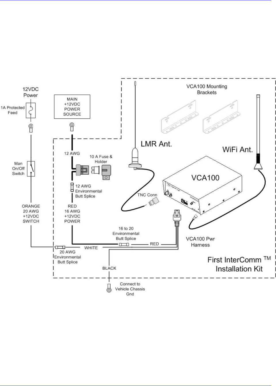
2.0 First InterComm™ System Description
The FICS (Figure 1 below) consists of:
• VCA100 unit, matched to user’s existing radio network frequencies
• Vehicle-mounted Wireless Fidelity (Wi-Fi) antenna
• Vehicle-mounted Land Mobile Radio (LMR) antenna, matched to user’s existing
radio network frequencies
• Remote On/Off switch
• FICS Talk Group Software (optional capability)
First InterComm
™
System VCA100 Installation Guide
A29799 rev A Page 7
PROPRIETARY INFORMATION: This document contains trade secrets and commercial or financial information that is the property of BAE
Systems Electronics and Integrated Solutions (E&IS). Further dissemination or disclosure of this information is strictly prohibited without
the written permission of BAE Systems.
The system operates on 12VDC vehicle power through an independent cab-mounted
switch. There are no speakers, microphones, or other vehicle tie-ins.
Eleven VCA100 models are available to cover the LMR bands (see Table 1 below). The
LMR antenna must match the frequency band of the VCA100 model being installed. A
standard, roof mounted 2.4 GHz 802.11 antenna is used for all VCA100 models.
Figure 1. Typical VCA100 Vehicle Installation
First InterComm
™
System VCA100 Installation Guide
Page 8 A29799
PROPRIETARY INFORMATION: This document contains trade secrets and commercial or financial information that is the property of BAE
Systems Electronics and Integrated Solutions (E&IS). Further dissemination or disclosure of this information is strictly prohibited without
the written permission of BAE Systems.
Table 1. First InterComm™ System VCA100 Models
Model Protocol Encryption LMR Band Kenwood Radio
Module Frequency
Range
VCA100-L1FCGX FM None VHF Low Band TK-190K 29.7 – 37 MHz
VCA100-L2FCGX FM None VHF Low band TK-190K2 35 – 50 MHz
VCA100-V1FCGX FM None VHF High Band TK-2180K 136 - 174 MHz
VCA100-V1PCGX FM/P25 None VHF High Band TK-5210K 136 - 174 MHz
VCA100-V1PAGX FM/P25 DES/AES VHF High Band TK-5210K 136 - 174 MHz
VCA100-V1PDGX FM/P25 DES VHF High Band TK-5210K 136 - 174 MHz
VCA100-U1FCGX FM None UHF TK-3180K 450 - 520 MHz
VCA100-81FCGX FM None 800 TK-480SK 806 - 870 MHz
VCA100-81PCGX FM/P25 None 800 TK-5400K 806 - 870 MHz
VCA100-81PDGX FM/P25 DES 800 TK-5400K 806 - 870 MHz
VCA100-91FCGX FM None 900 TK-481SK 896 - 941 MHz
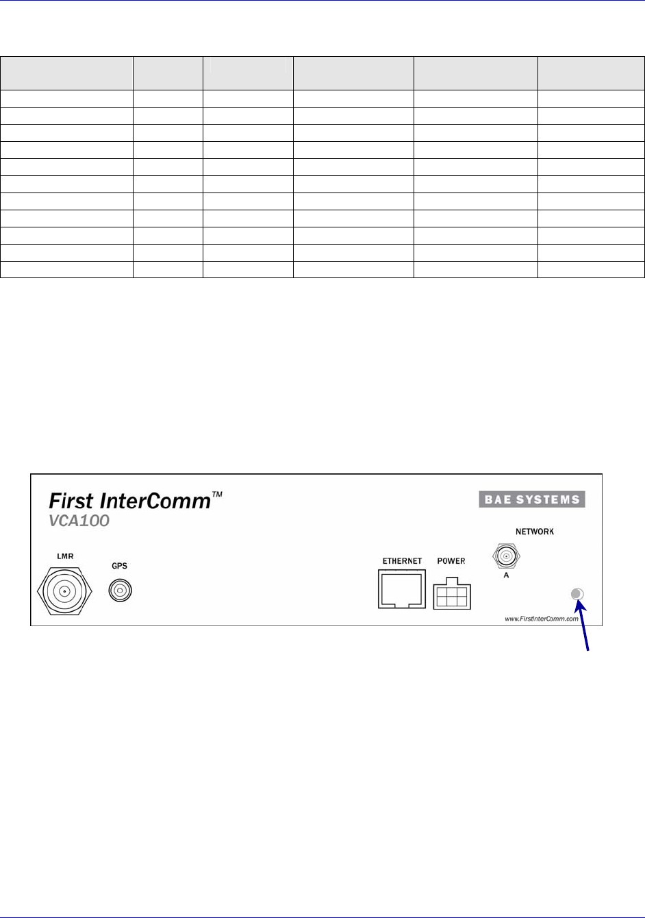
2.1 Vehicle Communications Assembly, Model VCA100
The VCA100 (Figure 2 below) is mounted in a vehicle and has no operator controls
other than a remote power-on switch. Once initialized, VCA100 operations are
transparent to the operator. Responders need only set their radio equipment to the pre-
designated interoperability channel to monitor or speak to members of other radio
networks at the site. The specific VCA100 model is selected based on the radio
frequencies used by the participating department (see Appendix A).
Figure 2. First InterComm™ System VCA100 Unit
• LMR
: 2 - way radio antenna connection, TNC.
• GPS
: Reserved for future implementation.
• Ethernet
: Factory use only.
• Power
:
• Network
: Wireless antenna port A, reverse polarity SMA connector.
• Activity Indicator: Power On, Built in Test indicator light.
• LMR
: 2 - way radio antenna connection, TNC.
• GPS
: Reserved for future implementation.
• Ethernet
: Factory use only.
• Power
: Nominal 13.6V DC and 1.75 A max
• Network
: Wireless antenna port A, reverse polarity SMA connector.
• Activity Indicator:
Activity
Indicator
On/Off control is via cab mounted switch toggle switch
First InterComm
™
System VCA100 Installation Guide
A29799 rev A Page 9
PROPRIETARY INFORMATION: This document contains trade secrets and commercial or financial information that is the property of BAE
Systems Electronics and Integrated Solutions (E&IS). Further dissemination or disclosure of this information is strictly prohibited without
the written permission of BAE Systems.
2.2 VCA100 Power Connector
The VCA100 uses three (3) pins of a 6-pin Molex connector as shown in Figure 3.
Figure 3. VCA100 Power Harness Connector – Front View
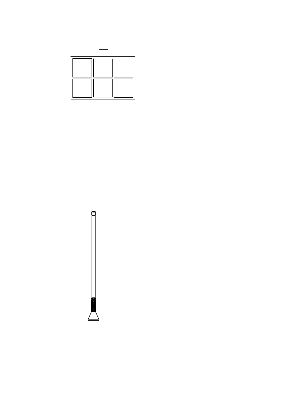
2.3 WiFi Antenna
The standard WiFi antenna for all VCA100 installations is the Comtelco Model A10245B
(Figure 4), a 2.4 GHz 802.11 roof mounted antenna, with elevated feed to rise above
cab obstructions and light bars. Gain is 3 dBi without ground plane, 5 dBi with ground
plane. Through mount is the Comtelco Model MBZM-10R/PI with 14’ micro-loss cable
and factory terminated SMA connector.
Figure 4. Standard Comtelco WiFi Antenna
2.4 Land Mobile Radio Antenna
A LMR antenna must match the frequency of the specific VCA100 model being installed
on the vehicle. Appendix A lists recommended LMR antennas that may be used with
various VCA100 models.
Front View of
Molex Connecto
r
Front View of
Molex Connecto
r
1 2 3
4 5 6
1 2 3
4 5 6
1 2 3
4 5 6
NC
+12
Switch
+12
VDC VDC
NC
+12
VDC
Pwr
+12
VDC
Pwr
NC
Gnd
Height: 14 inches
Mount: Standard TAD/NMO
Gain: 5 dBi with ground plane
Mechanical: Built-in shock spring
First InterComm
™
System VCA100 Installation Guide
Page 10 A29799
PROPRIETARY INFORMATION: This document contains trade secrets and commercial or financial information that is the property of BAE
Systems Electronics and Integrated Solutions (E&IS). Further dissemination or disclosure of this information is strictly prohibited without
the written permission of BAE Systems.
3.0 Planning the Installation
3.1 Installation Kit Components
Table 2 lists the deliverable installation kit for the First InterComm™ System. Specific
antennas will vary depending on the LMR frequency. The material listed is based on
availability; equivalent products may be used.
Table 2. VCA 100 Vehicle Installation Kit
Description Part Number Vendor Qty
Vehicle Communications Assembly Model 100 (VCA100)
*includes screw, harness, and bracket below
Model number is
frequency dependent
BAE Systems 1
VCA100 Mounting Bracket BAE001131-01-LF BAE Systems 2
VCA100 Power Harness 8422765-2 BAE Systems 1
Screws, center sunk head, #6-32 x .500 lg na na 4
12 VDC Power Cable, 16 AWG (red) for Specification
SAEJ1128
WX16-2 (SXL 16 ga) Waytek, Inc 20’
12 VDC Power Cable, 20 AWG (orange) for Specification
SAEJ1128-GPT
WG20-3 (GPT 20 ga) Waytek, Inc 15’
Butt Splice, 16 ga Environmentally Sealed 31980 Waytek, Inc 2
Butt Splice, Step Down, 16ga to 20 ga, environmentally
sealed
38058 Waytek, Inc 1
Butt Splice, 20 ga Environmentally Sealed 30980 Waytek, Inc 2
ATO/ATC Fuse Holder with GXL wire 46047 Waytek, Inc 1
ATO/ATC Fuse, 10 A 46210 Waytek, Inc 1
LMR Antenna, through mount, with hardware Various Multiple 1
WiFi Antenna, elevated feed, 5dBi gain, 2.4GHz, through
mount, 3/4-inch hole
A10245B Comtelco 1
WiFi Through mount base and14’ cable with reverse
polarity (female) SMA connector
CEZM10-RP Comtelco 1
Table 3 lists typical Installer-supplied parts that are vehicle specific and not supplied
with the kit. Table 3. Installer-Supplied Parts
Description Part Number Vendor Quantity
SPST Switch, illuminating, 1 A (minimum) 44206 or similar Waytek, Inc 1
Ground Wire, 18 AWG (black) Varies Varies As Required
Ring Terminal, size as needed (Gnd) Varies Varies 2
Terminals, size as needed (switch) Varies Varies 3
Terminal, size as needed (main power cut in) Varies Varies 1
Grommet, rubber, various sizes Varies Varies As Required
Cable Ties, Nylon Varies Varies As Required
Cable Tie mount, 4-way Varies Varies As Required
Screws, self tapping, #8-32, .500 lg Varies Varies 9
Washers, size and type as needed Varies Varies As Required
First InterComm
™
System VCA100 Installation Guide
A29799 rev A Page 11
PROPRIETARY INFORMATION: This document contains trade secrets and commercial or financial information that is the property of BAE
Systems Electronics and Integrated Solutions (E&IS). Further dissemination or disclosure of this information is strictly prohibited without
the written permission of BAE Systems.
3.2 Tools and Test Equipment
Table 4 lists details of the test equipment and software required to install the FICS
VCA100. These comprise:
• A laptop computer equipped with WiFi capability, loaded with Windows® XP1
Operating System, Service Pack 2, and BAE Systems supplied software (required to
upload user-specific parameters into the VCA100). The laptop is also used to test
the FICS VCA100 after installation.
• A watt meter to perform VSWR test.
• A volt/ohmmeter to perform voltage and resistance checks.
Table 4. Required Equipment and Software
Description Part Number Vendor Quantity
Laptop PC with Windows XP, Service Pack 2 Varies Varies 1
BAE Systems approved 2.4 GHz Wireless
Network Card
List to be provided List to be provided 1
BAE Systems First InterComm™ System
Installers CD
TBD BAE Systems 1
Voltage/Resistance Meter (DVM or VOM) Varies Varies 1
Watt Meter w/ cables, slugs, and adapters Model 43 or
equivalent
Bird or equivalent 1
Table 5 lists recommended tools for the First InterComm™ System installation.
Equivalent substitutes may be used as necessary.
Table 5. Recommended Tools for First InterComm™ System Installation
Tool Model/Specification
Screwdrivers, Phillips Head #1 and #2 flathead
Non-insulated Crimp Tool Thomas & Betts WT-111-M
Crimp Tool, Ratcheting Coaxial Cambridge 24-9960P
Hole Saw, 3/4-inch with depth
protection
Ripley HSK 19 or Antenex® HS34
Non-Metallic Fish Tape Klein-Lite® 50156, 25 feet
Clutch-type Screw Gun Makita® #6096DWE, #1 and #2 Phillips-Head bits
Pliers Slip Jaw
Electric Drill 3/8-inch, with HSS bits
De-Burring Tool
Socket Set Quarter Inch
Wire Cutters Flush-cut and large
RF Cable Termination Kit For SMA and TNC connectors
Heat Gun
1 Windows is a registered trademark of Microsoft Corporation

First InterComm
™
System VCA100 Installation Guide
Page 12 A29799
PROPRIETARY INFORMATION: This document contains trade secrets and commercial or financial information that is the property of BAE
Systems Electronics and Integrated Solutions (E&IS). Further dissemination or disclosure of this information is strictly prohibited without
the written permission of BAE Systems.
3.3 System Component Locations
WARNING
WHEN SELECTING LOCATIONS FOR FIRST INTERCOMM™ SYSTEM COMPONENTS,
AVOID HIGH FREQUENCY (HF) NOISE PRODUCERS AND DO NOT RUN DC POWER
FEEDS TO THE VCA100 PARALLEL TO IGNITION CIRCUITS, ELECTRONIC MODULES,
OR SIMILAR ITEMS. AVOID RUNNING POWER LEADS IN PARALLEL WITH VEHICLE
WIRING OVER LONG DISTANCES.
3.3.1 VCA100
The VCA100 has no operator interfaces other than an activity indicator. Also, the unit
has no fan; it is convection cooled and does not require any special ventilation.
However, it is not environmentally sealed and must be installed in a protected area
where it will not be exposed to any fluids (THE ENGINE COMPARTMENT IS NOT ACCEPTABLE).
The optimum location is one in which the VCA100 is out of the way, its face plate and
cable connections protected as much as possible, and there are at least six inches of
space around the VCA100 to allow air circulation. Additionally, attempt to provide line of
sight to the activity indicator.
Plan for cable management and strain relief loops for the cables. Cable ties and
mounts are needed to prevent cable movement and vibration.
3.3.2 WiFi Antenna
The WiFi antenna location has highest priority because the antenna’s relatively short
range has the greatest effect on system performance. Mount the antenna as high as
possible on the cab roof, and as close as possible to the vehicle’s centerline to provide
360-degree coverage. The antenna requires a metal ground plane to achieve its full
5dBi of gain.
We recommend keeping the antenna at least 12 inches away from any light bars or
other antennas. The maximum designed distance from the VCA100 to the WiFi
antenna is 14 feet, the standard cable length that comes with the antenna. Extensions
are not recommended since they will significantly reduce the WiFi range. If an
extension cannot be avoided substitute the antenna mount with a cable of sufficient
length (no splices or adapters) and equivalent or better loss specifications at 2.4 GHz
than what is supplied.
Certain vehicles do not allow locating the antenna in the center or center-rear of the
roof. In this case, the next best antenna location is on the direct center of the trunk lid.
Be aware, however, that this location will degrade the WiFi range. The mounting area
under the antenna must be a flat, metallized ground plane.
First InterComm
™
System VCA100 Installation Guide
A29799 rev A Page 13
PROPRIETARY INFORMATION: This document contains trade secrets and commercial or financial information that is the property of BAE
Systems Electronics and Integrated Solutions (E&IS). Further dissemination or disclosure of this information is strictly prohibited without
the written permission of BAE Systems.
3.3.3 Land Mobile Radio Antenna
The LMR antenna must match the frequency of the specific VCA100 model being
installed on the vehicle. Many LMR antennas will require cutting to ensure proper
VSWR match on the customer’s frequency. Ensure that the new LMR antenna is not
installed in close proximity to any existing LMR antennas.
We recommend keeping the antenna at least 12 inches away from any light bars,
antennas, or other roof-mounted equipment.
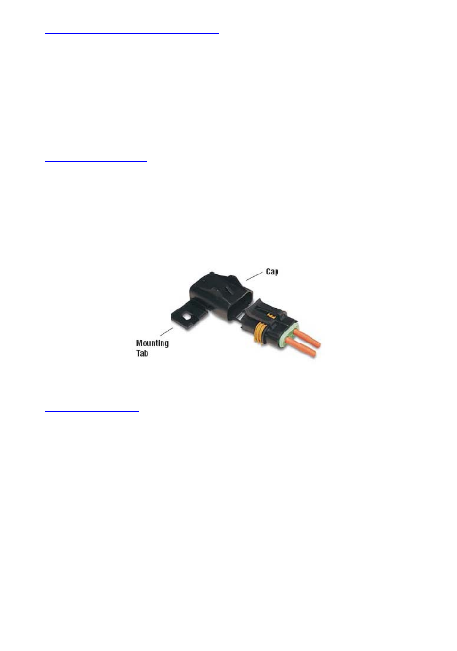
3.3.4 Power and Fuse
The vehicle’s main power source is connected to the VCA100 by the DC power cable
(red) that passes through an inline fuse. Locate the fuse as close as possible to the
power source and splice it in with weatherproof butt splices (SUPPLIED). Mount the fuse
assembly (Figure 5) to facilitate maintenance. Splice the power line to the VCA100
power harness (SUPPLIED) using the step-down splice (SUPPLIED) to accommodate the
dissimilar wire gauges.
Figure 5. In-Line Fuse
3.3.5 Manual Switch
A second, low current, power line (orange) must run through a cab-mounted manual
toggle switch to the VCA100 power connector SWITCH input (pin 2). This switch is not
supplied in the deliverable installation kit because User-specific vehicle installations
vary; i.e., switch location is a function of User requirements and vehicle constraints. An
illuminated manual switch, appropriately labeled, is recommended. Connect the switch
to a 1-ampere fuse-protected vehicle power source.
First InterComm
™
System VCA100 Installation Guide
Page 14 A29799
PROPRIETARY INFORMATION: This document contains trade secrets and commercial or financial information that is the property of BAE
Systems Electronics and Integrated Solutions (E&IS). Further dissemination or disclosure of this information is strictly prohibited without
the written permission of BAE Systems.
4.0 Installation Procedures
4.1 VCA100 Unit
1. Record the VCA100 model number and serial number on the INSTALLATION SIGN
OFF SHEET (see Appendix E). Tag is not viewable after mounting.
2. Carefully inspect the area selected for the VCA100 unit to ensure that the area is
free of physical or electrical obstacles that could interfere with proper installation,
maintenance, or operation.
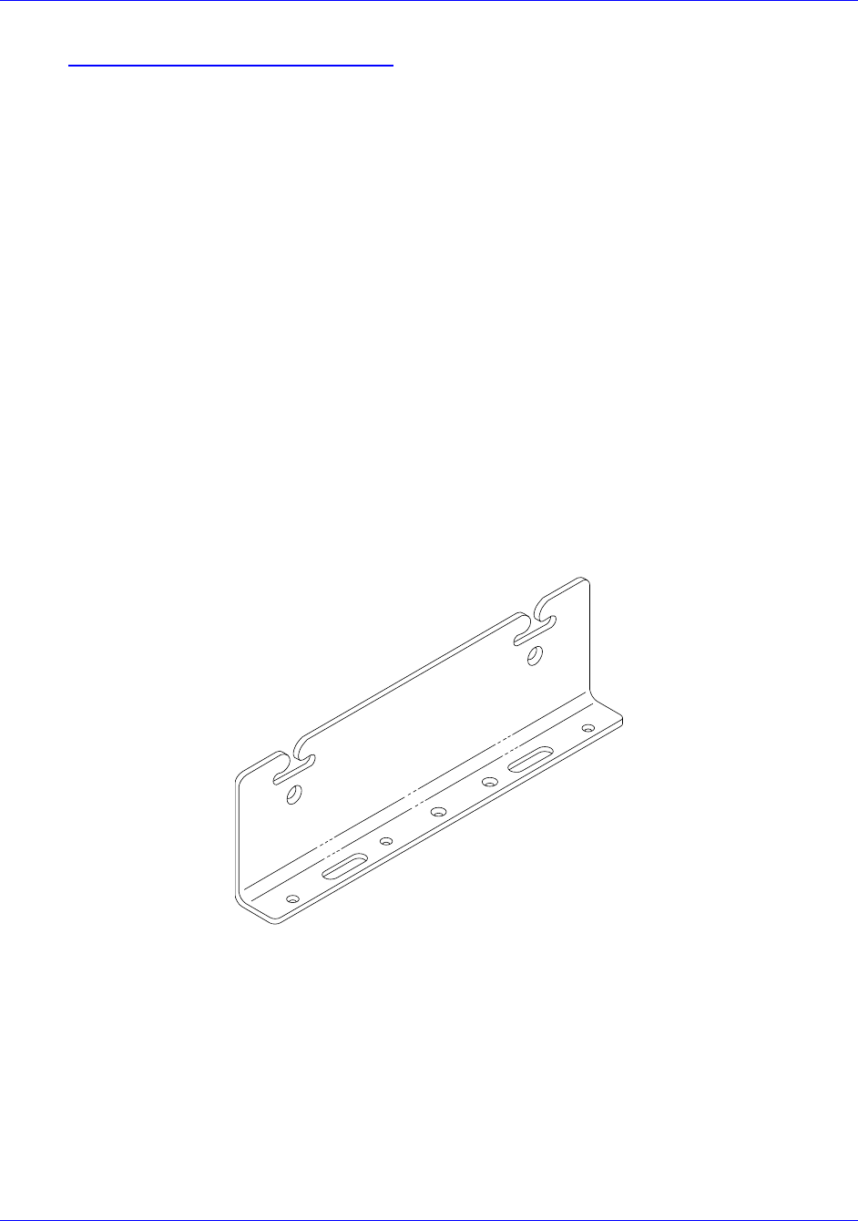
3. Attach the two L-shaped mounting brackets (Figure 6) to the sides of the VCA100
using four #6-32 countersunk machine screws if holes are used, or thumbscrews if
quick-release slots are used. Attach the wide edge of the bracket to the VCA100;
attach the narrow edge to the vehicle.
4. Place the VCA100 in its final location and scribe three bracket holes into the
vehicle on each side of the VCA100 for drilling. The VCA100 must be firmly
mounted to the vehicle.
5. Pre-drill six holes into the vehicle to accommodate self-tapping screws. The size
of the hardware used determines the size of the holes.
6. Mount the VCA100 to the vehicle with self-tapping screws.
Figure 6. VCA100 Mounting Bracket
4.2 WiFi Antenna
1. Verify the center pin of the WiFi antenna cable connector is female (reverse
polarity SMA). Carefully inspect the area selected for the WiFi antenna to ensure
that the area is free of physical or electrical obstacles that could interfere with
proper installation, maintenance, or operation.
2. Follow manufacturer’s installation instructions for external mounting of the WiFi
antenna.

First InterComm
™
System VCA100 Installation Guide
A29799 rev A Page 15
PROPRIETARY INFORMATION: This document contains trade secrets and commercial or financial information that is the property of BAE
Systems Electronics and Integrated Solutions (E&IS). Further dissemination or disclosure of this information is strictly prohibited without
the written permission of BAE Systems.
3. Run the RF cable from the WiFi antenna to the VCA100. Use cable ties and
mounts to protect the cable. Grommet all through holes to prevent cable chaffing.
4. Connect the WiFi RF cable in a straight path to the VCA100 NETWORK A SMA
connector. Use cable ties and mounts to keep the cable from moving or placing
stress on the SMA connector.
4.3 Land Mobile Radio Antenna
1. Carefully inspect the area selected for the LMR antenna to ensure that the area is
free of physical or electrical obstacles that could interfere with proper installation,
maintenance, or operation.
2. Follow the LMR manufacturer’s installation instructions for mounting of the
antenna and for trimming it to the user’s frequency.
3. Run the RF cable from the LMR antenna to the VCA100. Use cable ties and
mounts to protect the cable. Grommet all through holes to prevent cable chaffing.
4. At the VCA100, lay in a stress relief loop and cut the LMR RF cable to length.
Terminate the cable with a TNC connector in accordance with manufacturer’s
instructions. Connect to the VCA100 LMR TNC connector.
4.4 DC Power
1. Carefully inspect the area selected for the DC power lines to ensure that the area is
free of physical or electrical obstacles that could interfere with proper installation,
maintenance, or operation.
2. Starting at the VCA100, locate a suitable chassis ground as close to the VCA100 as
possible. If necessary, scrape and remove paint to reach bare metal. Drill chassis
and use a self-tapping screw and star washer to create a chassis ground.
3. Locate the 20 AWG ground (black) wire of the VCA100 power harness (Pin 4). Cut
and strip the outer cable jacket as required. Cut the end of the ground wire to
length, terminating with a ring terminal, and secure the terminal to the chassis
ground created in Step 2 (see Figure 3).
4. Lay in a stress relief loop and use cable ties and mounts to secure the power
harness to the vehicle and prevent vibration or strain on the power connector.
5. Connect a suitable length of red 16 AWG wire to the VCA100 power harness main
power (red) wire (Pin 1) (see Figure 3) using the 16 to 20 step-down environmental
splice (SUPPLIED). Run the other end of the wire to the VCA100 in-line fuse. Use
cable ties and mounts to protect the cable. Grommet all through holes to prevent
cable chaffing.
6. Connect a suitable length of orange 20 AWG wire to the VCA100 power harness
12V Switch (white) wire (Pin 2) (see Figure 3) using the 20 AWG environmental
splice (SUPPLIED). Run the other end of the wire to the planned location of the

First InterComm
™
System VCA100 Installation Guide
Page 16 A29799
PROPRIETARY INFORMATION: This document contains trade secrets and commercial or financial information that is the property of BAE
Systems Electronics and Integrated Solutions (E&IS). Further dissemination or disclosure of this information is strictly prohibited without
the written permission of BAE Systems.
VCA100 On/Off Switch. Use cable ties and mounts to protect the wire. Grommet all
through holes to prevent cable chaffing.
4.5 VCA100 On/Off Switch
1. Carefully inspect the area selected for the VCA100 On/Off Switch to ensure that the
area is free of physical or electrical obstacles that could interfere with proper
installation, maintenance, or operation.
2. Drill or cut an area to hold the lighted toggle switch. Mount and label the switch.
3. If the switch is illuminated, locate a suitable chassis ground as close to the new
power switch as possible. If necessary, scrape and remove paint to reach bare
metal. Drill chassis and use self-tapping screw and star washer to create a chassis
ground for the switch.
4. I f the switch is illuminated, connect a suitable length of black 20 AWG wire to the
ground lug of the VCA100 On/Off switch using an appropriate terminal. Cut other
end to length, terminate with a ring terminal, and secure the assembly to the chassis
ground created in step 3 above.
5. Locate the end of the orange 20 AWG switch extension wire from the VCA100
power harness and cut it to length to mate with the VCA100 On/Off switch. Connect
the wire to the power out lug of the VCA100 On/Off switch using an appropriate
terminal.
6. Use an appropriate terminal to connect a suitable length of orange 20 AWG wire to
the power in lug of the VCA100 On/Off switch. Connect the other end of the wire to
a 1A fuse-protected vehicle power source with appropriate terminal. Use cable ties
and mounts to protect the wire. Grommet through holes to prevent cable chaffing.
7. Reassemble any panels or consoles opened for installation of the switch.
4.6 Fuse Assembly
1. Carefully inspect the area selected for the fuse assembly to ensure that the area is
free of physical or electrical obstacles that could interfere with proper installation,
maintenance, or operation.
2. Drill into the vehicle at the proper location to receive the Fuse Assembly’s cap and
mounting tab. Remove fuse from holder and mount holder using a self-tapping
screw.
3. Locate the end of the red 16 AWG extension wire from the VCA100 Power harness
and cut it to length to mate with one end of the Fuse Assembly. Connect it to the
Fuse Assembly using a 12AWG environmental splice (SUPPLIED).
4. If the Fuse Assembly lead is too short, use an environmental splice (SUPPLIED)
connected to a suitable length of red 16AWG wire to extend the lead.
5. Connect the Fuse Assembly’s other wire to the vehicle’s load center or main
+12VDC power source using the appropriate termination.
First InterComm
™
System VCA100 Installation Guide
A29799 rev A Page 17
PROPRIETARY INFORMATION: This document contains trade secrets and commercial or financial information that is the property of BAE
Systems Electronics and Integrated Solutions (E&IS). Further dissemination or disclosure of this information is strictly prohibited without
the written permission of BAE Systems.
6. Use cable ties and mounts to protect the wire. Grommet all through holes to prevent
cable chaffing. Install VCA100 Fuse.
5.0 Initial Power Test
1. Before connecting to the VCA100, use a voltmeter at the VCA100 power harness
connector to check for a constant +12VDC, switched +12VDC, and ground (Figure 3
shows the VCA100 power connector).
2. Follow the steps as listed in Table 6. Correct any problems encountered before
proceeding to the next step.
3. Place check mark in Verified box after successful completion of test step.
Table 6. Initial Power Tests
Required Equipment: Volt/Ohm Meter
Step Procedure Expected Result Verified
1 Verify VCA100 power harness is
disconnected from VCA100 and energized VCA100 power harness
disconnected and energized
2 Probe the VCA100 power harness connector
Pin 1 for a constant +12 VDC Voltmeter reads vehicle power
as approximately +12VDC
3 Set the VCA100 power switch to ON Power switch is ON
4 Probe the VCA100 power harness connector
pin 2 for switched +12 VDC Voltmeter reads vehicle power
as approximately +12VDC
5 Set the VCA100 power switch to OFF VCA100 is OFF
6 Probe the VCA100 power harness connector
pin 2 for switched +12 VDC Voltmeter reads 0 VDC
7 Probe VCA100 power harness connector pin
4 (ground) to chassis ground with ohmmeter Good ground connection exists
8 Connect VCA100 power harness to VCA100. Items are connected.
9
Turn on VCA100 unit and monitor Activity
LED (see Figure 2) for Power On Built In Test
(PBIT) Result.
LED will illuminate for approx. 30 sec. during
initialization, extinguishes for 10 sec., then
illuminates and remains on if Power-on BIT is
successful.
Power-on BIT is successful.
Front View of
Molex Connecto
r
Front View of
Molex Connecto
r
1 2 3
4 5 6
1 2 3
4 5 6
1 2 3
4 5 6
NC
+12
Switch
+12
VDC VDC
NC
+12
VDC
Pwr
+12
VDC
Pwr
NC
Gnd

First InterComm
™
System VCA100 Installation Guide
Page 18 A29799
PROPRIETARY INFORMATION: This document contains trade secrets and commercial or financial information that is the property of BAE
Systems Electronics and Integrated Solutions (E&IS). Further dissemination or disclosure of this information is strictly prohibited without
the written permission of BAE Systems.
6.0 Programming Procedure
The VCA100 is delivered with operating software but must be updated with user-specific
parameters. Programming is done in two parts:
• BAE Systems’ supplied VCA MANAGER Program and utilities is used to update the
flash or to load new operating software.
• Installer supplied Serial/IP COM Port Redirector and Kenwood Radio programming
software is used to update the radio module.
All programming is done wirelessly by loading the software on an Installer supplied
maintenance laptop equipped with a BAE Systems approved wireless network card.
6.1 Preparation
1. Appendix B contains instructions for operating the Serial IP and the VCA MANAGER
Programs. See Kenwood documentation for operation of that software.
2. Consult with the end user department and discuss incorporating the VCA100 into
their standard operating procedures.
3. Collect and record the required VCA100 User information in Table 7.
4. Provide copies to Customer, BAE Systems, and retain copy for records.
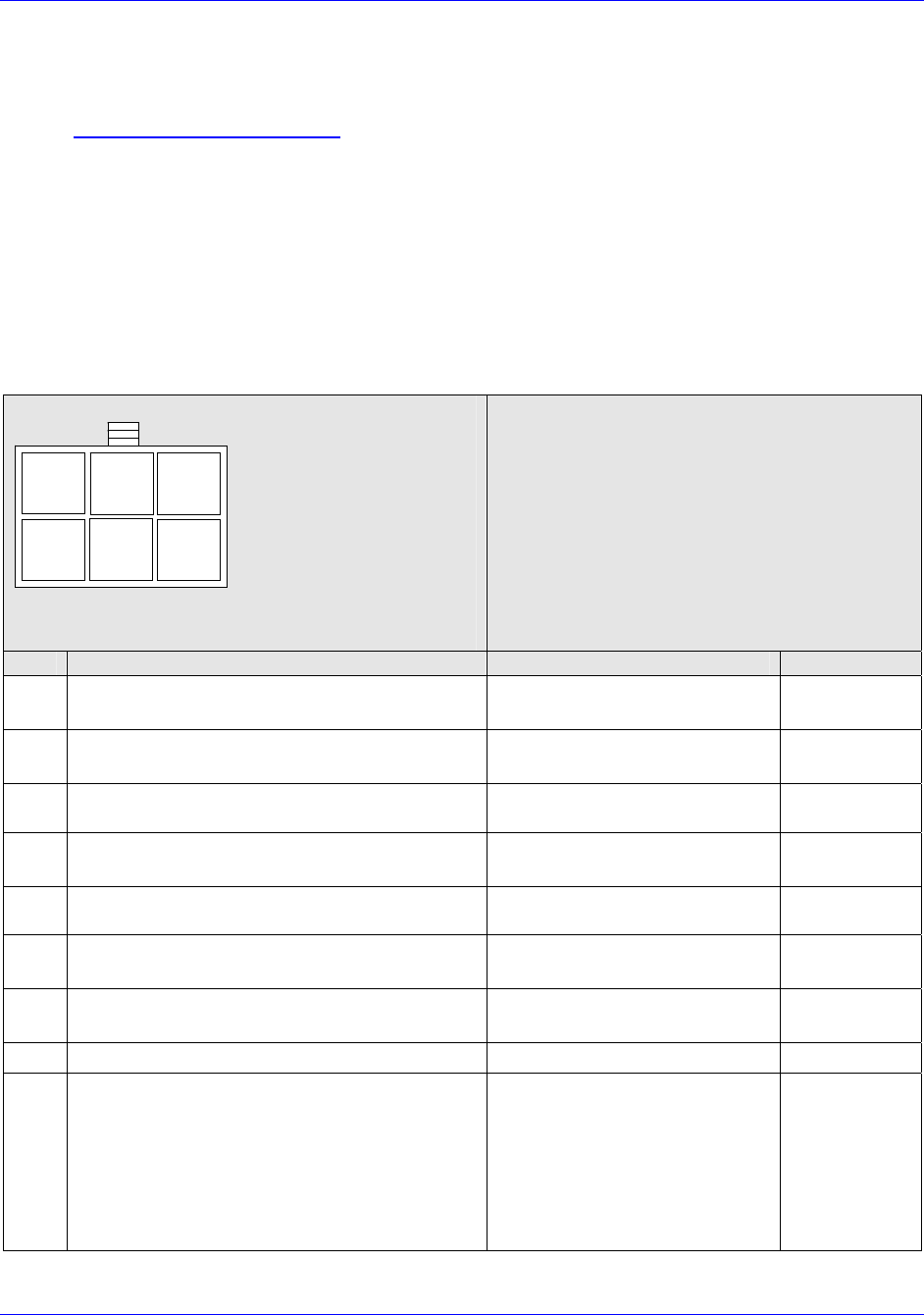
Table 7. Required User Information
Item Parameter Format User Data
1 Department Name Up to 128 Characters.
2 Vehicle ID Up to 128 Characters.
3 Vehicle Type Icon on WiFi network, e.g., fire,
police, ambulance.
4 Nickname Up to 16 Characters
5 LMR Bandwidth Wide (25 kHz) or
Narrow (12.5 kHz)
6 LMR Mode Analog or Digital
7 LMR Transmit Power High or Low
8 LMR Transmit Frequency Numeric entry in MHz
9 LMR Receive Frequency Numeric entry in MHz
10 LMR Transmit Private Line
Code Frequency or Alphanumeric ID
[e.g. 94.8Hz (2A)]
11 LMR Receive Private Line
Code Frequency or Alphanumeric ID
[e.g. 94.8Hz (2A)]
12 VCA100 ID Serial number on unit

First InterComm
™
System VCA100 Installation Guide
A29799 rev A Page 19
PROPRIETARY INFORMATION: This document contains trade secrets and commercial or financial information that is the property of BAE
Systems Electronics and Integrated Solutions (E&IS). Further dissemination or disclosure of this information is strictly prohibited without
the written permission of BAE Systems.
6.2 VCA100 Update Procedure
1. Perform the update in two parts: VCA MANAGER program and Kenwood Radio
software.
2. Follow the steps as listed in Table 8. Correct any problems encountered before
proceeding to the next step.
3. Place check mark in Verified box after successful completion of test step.
Table 8. VCA100 Configuration Procedure
Required Items:
a. VCA100 Installed in vehicle
b. User Parameters (Table 7 of this document).
c. Installer’s WiFi Laptop configured using BAE Systems’ software CD
d. Serial IP and Kenwood Radio programming software installed on laptop
Step Procedure Expected
Result Verified
1 Turn on VCA100. Wait one minute for boot up to complete. Booted
2 Turn on the laptop and connect to First_InterComm_Network. Connected
3 Execute VCA MANAGEMER program (see Appendix B in this
document) and input specific User Parameters. VCA100 will
reboot after committing changes.
Updated and
Rebooted
4 Launch Serial IP program. (see Appendix B in this document) Running
5 Use Serial IP program to enable a virtual COM port between
COM2 and the VCA100. (see Appendix B in this document) Enabled
6 Launch the appropriate Kenwood Radio programming software for
the VCA100 and set COM port to COM2. (see Table 1, First
InterComm™ System VCA100 Models)
Running,
COM2
7 Program VCA100 Radio module with specific User LMR
frequencies and PL Codes. Programmed
8 Close Kenwood, SERIAL IP and VCA MANAGER program. Prepare
to run System Functional Test of the Unit Test Plan to verify
updates. Closed
First InterComm
™
System VCA100 Installation Guide
Page 20 A29799
PROPRIETARY INFORMATION: This document contains trade secrets and commercial or financial information that is the property of BAE
Systems Electronics and Integrated Solutions (E&IS). Further dissemination or disclosure of this information is strictly prohibited without
the written permission of BAE Systems.
7.0 Unit Test Plan
Follow the test procedures described in Paragraphs 7.1 and 7.2. Correct any problems
found, retest, and record final results on the INSTALLATION SIGN OFF SHEET (Appendix E).
7.1 LMR Antenna VSWR Test
Perform an antenna VSWR test using an in-line wattmeter with appropriate frequency
range and power levels, and low loss cable and connectors. The LMR output is
expected to be in the range of 3 to 5 watts. Record results in Table 9.
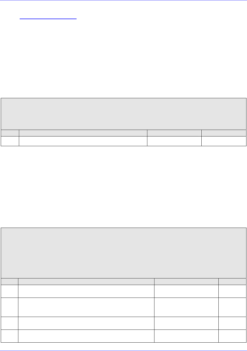
Table 9. LMR Antenna VSWR Test Results
Required Material:
a. VCA100 installed in vehicle with LMR Antenna and cable under test
b. Antenna OEM’s VSWR procedure (or standard industry accepted VSWR procedure)
c. Watt meter
Step Procedure Requirement Result
1 Perform LMR VSWR procedure. Record result. < 2:1 VSWR (10%)
7.2 System Functional Test
1. Follow the test steps in Table 10 to verify the VCA100’s key functions and its ability
to operate in a network.
2. Correct any problems found, retest, and record final results on the INSTALLATION SIGN
OFF SHEET (Appendix E).
3. Obtain required signatures and send to BAE Systems, retain file copy.
Table 10. System Functional Test Results
Required Material:
a. VCA100 under test installed in vehicle and configured with user parameters.
b. Known good user mobile or portable radio with the same Frequency and PL Code as the
VCA100 under test.
c. Known good second VCA100 and mobile or portable radio set to a different frequency than the
VCA100 under test with a line-of-sight path more than 100 feet but less than 300 feet
separation between the VCAs.
Step Procedure Expected Result Verified
1 Turn on VCA100 under test. Wait one minute for boot
up to complete. Boot up complete
2 Turn on mobile or portable radio associated with the
VCA100 under test. Verify the proper channel is
selected. Proper channel selected
3 Turn on known good second VCA100. Wait one minute
for boot up to complete. Boot up complete
4 Turn on mobile or portable radio associated with known
good VCA100. Verify proper channel is selected. Proper channel selected

First InterComm
™
System VCA100 Installation Guide
A29799 rev A Page 21
PROPRIETARY INFORMATION: This document contains trade secrets and commercial or financial information that is the property of BAE
Systems Electronics and Integrated Solutions (E&IS). Further dissemination or disclosure of this information is strictly prohibited without
the written permission of BAE Systems.
5 Verify 2-way communication through both units occurs
without distortion, breakup, or dropouts. Record final
result on Installation Sign Off Sheet. Communication is good
8.0 Troubleshooting
Appendix D contains detailed troubleshooting procedures for the FICS.
IMPORTANT
• If the FICS appears to interfere with incident site operations,
immediately turn off every VCA unit (and FICS Talk Group Software if
in use), and return to normal SOP.
• If Talk Group Software or Incident Commander Workstation (laptop)
computer problems occur, the VCA100 units will remain in their last
assigned Talk Groups. If the laptop or software is not functional, and
communication is needed between all responders, power-cycle all
VCA100s.
9.0 BAE Support Information
• Telephone Support: (603) 759-1027
• E-Mail: firstintercomm.eis@baesystems.com
• Web: http://www.firstintercomm.com
10.0 Companion Documentation
• First InterComm
™
System User Guide, Document No. A29798.
• First InterComm
™
System Talk Group Software, Document No. A29800.

First InterComm
™
System VCA100 Installation Guide
Page 22 A29799
PROPRIETARY INFORMATION: This document contains trade secrets and commercial or financial information that is the property of BAE
Systems Electronics and Integrated Solutions (E&IS). Further dissemination or disclosure of this information is strictly prohibited without
the written permission of BAE Systems.
Appendix A
Recommended LMR Antennas
Table A-1. Recommended LMR Antennas
Model Suggested Antennas LMR Band Frequency Range Protocol Encryption
VCA100-L1FCGX C27, C30, C34 VHF Low Band 29.7 – 37 MHz FM None
VCA100-L2FCGX C34, C37, C40, C47 VHF Low band 35 – 50 MHz FM None
VCA100-V1FCGX B1323 VHF High Band 136 - 174 MHz FM None
VCA100-V1PCGX B1323 VHF High Band 136 - 174 MHz FM/P25 None
VCA100-V1PAGX B1323 VHF High Band 136 - 174 MHz FM/P25 DES/AES
VCA100-V1PDGX B1323 VHF High Band 136 - 174 MHz FM/P25 DES
VCA100-U1FCGX B4503, B4703, B4903 UHF 450 - 520 MHz FM None
VCA100-81FCGX B8063 800 806 - 870 MHz FM None
VCA100-81PCGX B8063 800 806 - 870 MHz FM/P25 None
VCA100-81PDGX B8063 800 806 - 870 MHz FM/P25 DES
VCA100-91FCGX B8963 900 896 - 941 MHz FM None
Table A-2. LMR Antenna Specifications
Manufacturer Part Number Frequency
(MHz) Gain
(dBi) Wave
Length Load Tunable Height
(inches)
Laird C27 26.75-31 Unity 1/4 Coil Style Yes 52.5
Laird C30 30-35 Unity 1/4 Coil Style Yes 52.5
Laird C34 34-37 Unity 1/4 Coil Style Yes 52.5
Laird C37 37-40 Unity 1/4 Coil Style Yes 52.5
Laird C40 40-47 Unity 1/4 Coil Style Yes 52.5
Laird C47 47-50 Unity 1/4 Coil Style Yes 52.5
Laird B1323 132-174 3 5/8 Coil Style Yes 57
Laird B4503 450-470 3 5/8 Coil Style Yes 13
Laird B4703 470-490 3 5/8 Coil Style Yes 12.5
Laird B4903 490-512 3 5/8 Coil Style Yes 12.5
Laird B8063 806-866 3
5/8 Base Yes 4 7/8
Laird B8963 896-970 3
5/8 Base - 4 7/8
First InterComm
™
System VCA100 Installation Guide
A29799 rev A Page 23
PROPRIETARY INFORMATION: This document contains trade secrets and commercial or financial information that is the property of BAE
Systems Electronics and Integrated Solutions (E&IS). Further dissemination or disclosure of this information is strictly prohibited without
the written permission of BAE Systems.
Appendix B
VCA100 Software Programs and Utilities
B.1 BAE Systems VCA Manager Program
The VCA Manager is used to connect wirelessly to the VCA100 in order to change User
parameters and upgrade software on the VCA100. The procedure is to:
1. Power up the VCA100(s) that will be updated and then power up the laptop so that a
First InterComm Network is established.
2. Launch the First InterComm VCA Manager software using the Windows start button
to navigate to First InterComm and click on the VCA Manager menu item.
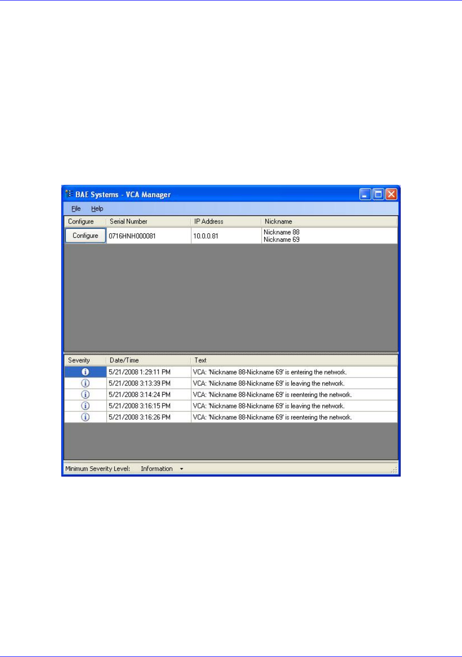
Figure B-1.1 First InterComm™ VCA Manager Window
3. VCAs in the network will will be listed in the top field of the window. Click on
Configure next to the serial number of the VCA to be updated.
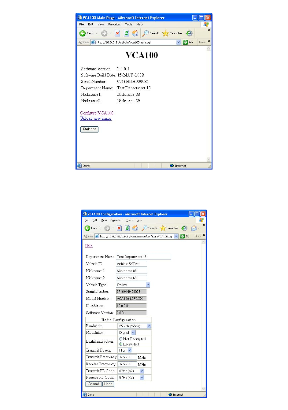
4. An Internet Explore window will open for that VCA. Click on Configure VCA100.
First InterComm
™
System VCA100 Installation Guide
Page 24 A29799
PROPRIETARY INFORMATION: This document contains trade secrets and commercial or financial information that is the property of BAE
Systems Electronics and Integrated Solutions (E&IS). Further dissemination or disclosure of this information is strictly prohibited without
the written permission of BAE Systems.
Figure B-1.2 VCA Manager Configuration Tool
5. Enter user name and password in the pop up window and click Validate. (See your
BAE Systems representative for your user name and password.)
Figure B-1.3 VCA Manager Configuration Window
First InterComm
™
System VCA100 Installation Guide
A29799 rev A Page 25
PROPRIETARY INFORMATION: This document contains trade secrets and commercial or financial information that is the property of BAE
Systems Electronics and Integrated Solutions (E&IS). Further dissemination or disclosure of this information is strictly prohibited without
the written permission of BAE Systems.
6. Fill in the fields with new parameter information. Click on Commit to update.
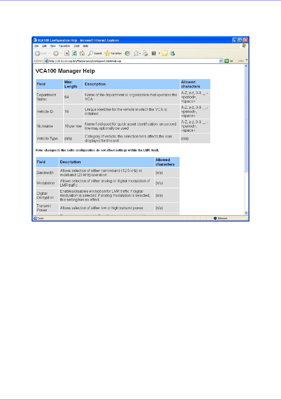
Figure B-1.4 First InterComm™ VCA Manager Help Window
7. Clicking on Help will open the VCA00 manger Help page, which provide detailed
information about each of the data fields.
8. If the VCA100 software requires upgrading, click on Upload new software image at
the main VCA100 Internet Explorer window (Figure B-1.2). Log in with name and
password then click on Browse and navigate to the location of the new software file.
9. Click on the filename to enable the Update button. The field next to the button will
display the filename.
10. Click on Update and monitor progress.
11. Perform the SYSTEM FUNCTIONAL TEST described in Paragraph 7.2 to verify that the
newly programmed VCA100 communicates with other VCA100 units.
First InterComm
™
System VCA100 Installation Guide
Page 26 A29799
PROPRIETARY INFORMATION: This document contains trade secrets and commercial or financial information that is the property of BAE
Systems Electronics and Integrated Solutions (E&IS). Further dissemination or disclosure of this information is strictly prohibited without
the written permission of BAE Systems.
B.2 Serial IP Program
Serial/IP Redirector software, a utility program, creates a virtual COM port that
associates an IP address with a hardware COM port. This allows RS-232 programming
with Kenwood software over a wireless link to the VCA100 Radio Module. The
procedure is to:
1. Start the VCA MANAGER PROGRAM (Paragraph B.1) to enable access to the First
InterComm™ network and the VCA100 being programmed.
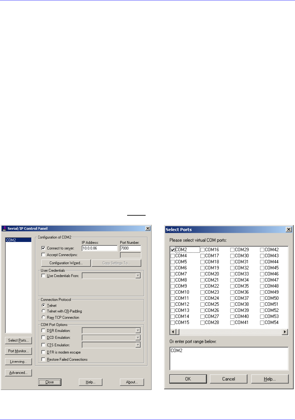
2. Start the Serial IP Panel (Figure B-2) using the Windows start button; i.e.,
START
Æ
ALL PROGRAMS
Æ
SERIAL IP
Æ
CONTROL PANEL
3. Enter the target VCA100’s IP address into the IP ADDRESS BOX (10.0.0.X), where X is
the last digits of the unit’s serial number. Enter 7000 into the Port Number box.
4. Set the COM port to COM2 in the Serial IP Control Panel;
SELECT PORTS...
Æ
COM2
Æ
OK
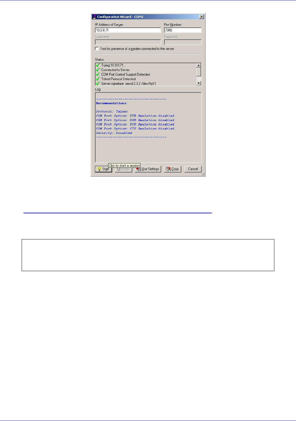
5. Click on the Configuration Wizard (Figure B-3) in the SERIAL IP CONTROL PANEL.
6. Click Start in the wizard.
7. Watch the STATUS window in the Configuration Wizard to verify that the TELENET
session progresses successfully and that all check marks are green.
8. Click on Use Settings in the CONFIGURATION WIZARD to complete the Serial IP setup
and enable the virtual Com Port. (*NOTE: It is very easy to forget this step)
Figure B-2.1 Serial IP Control Panel and Select Port Windows
First InterComm
™
System VCA100 Installation Guide
A29799 rev A Page 27
PROPRIETARY INFORMATION: This document contains trade secrets and commercial or financial information that is the property of BAE
Systems Electronics and Integrated Solutions (E&IS). Further dissemination or disclosure of this information is strictly prohibited without
the written permission of BAE Systems.
Figure B-2.2 Serial IP Program Configuration Wizard
B.3 Kenwood Radio Programming Software
Kenwood Radio Programming software is used as a utility program to configure the
VCA100 Radio Module.
NOTE
IT IS REQUIRED TO PROGRAM ALL RADIOS PER THE PARAMETERS IN TABLE B-2
BELOW.
The procedure is to:
1. Start the VCA Manager Program and Serial IP program (Paragraph B.1 & B.2
above) to link the COM2 port to the VCA100 being programmed.
2. Consult Table B-1 below to find the First InterComm™ System VCA100 Model and
then launch the corresponding Kenwood Radio programming software for the
VCA100 being programmed.
3. Set COM port used in the Kenwood software to COM2.
4. Consult Table B-2 below, Required Kenwood Radio Parameters To Be
Programmed, and program the values appropriate to the model being updated.
5. Consult Table 7, Required User Information, and program the appropriate values
into the VCA100 radio module.

First InterComm
™
System VCA100 Installation Guide
Page 28 A29799
PROPRIETARY INFORMATION: This document contains trade secrets and commercial or financial information that is the property of BAE
Systems Electronics and Integrated Solutions (E&IS). Further dissemination or disclosure of this information is strictly prohibited without
the written permission of BAE Systems.
Model Protocol Encryption Frequency
Range Kenwood
Radio Module
Kenwood
Radio Prgm
S/W
VCA100-L1FCGX FM None 29.7 – 37 MHz TK-190K KPG-59D
VCA100-L2FCGX FM None 35 – 50 MHz TK-190K2 KPG-59D
VCA100-V1FCGX FM None 136 - 174 MHz TK-2180K KPG-89D
VCA100-V1PCGX FM/P25 None 136 - 174 MHz TK-5210K KPG-95D
VCA100-V1PAGX FM/P25 DES/AES 136 - 174 MHz TK-5210K KPG-95D
VCA100-V1PDGX FM/P25 DES 136 - 174 MHz TK-5210K KPG-95D
VCA100-U1FCGX FM None 450 - 520 MHz TK-3180K KPG-89D
VCA100-81FCGX FM None 806 - 870 MHz TK-480SK KPG-49D
VCA100-81PCGX FM/P25 None 806 - 870 MHz TK-5400K KPG-78D
VCA100-81PDGX FM/P25 DES 806 - 870 MHz TK-5400K KPG-78D
VCA100-91FCGX FM None 896 - 941 MHz TK-481SK KPG-49D
Table B-1 VCA100Model Characteristics
Kenwood Radio
Module Squelch
Level Timeout Warning Tone Minimum
Volume
Setting
Maximum
Volume
Setting
TK-190K 8 120 sec Disable 4 n/a
TK-190K2 8 120 sec Disable 4 n/a
TK-2180 120 sec Disable 9 9
TK-3180 120 sec Disable 9 9
TK-5210 120 sec Disable 11 11
TK-5400 120 sec Disable 13 n/a
TK-480 120 sec Disable 3 n/a
Table B-2 Required Kenwood Radio Parameters To Be Programmed

First InterComm
™
System VCA100 Installation Guide
A29799 rev A Page 29
PROPRIETARY INFORMATION: This document contains trade secrets and commercial or financial information that is the property of BAE
Systems Electronics and Integrated Solutions (E&IS). Further dissemination or disclosure of this information is strictly prohibited without
the written permission of BAE Systems.
Appendix C
Acronyms and Abbreviations
ABS Antilock Brake System
AES Advanced Encryption Standard
ATC Automotive Blade-Type Fuse
ATO Automotive Blade-Type Fuse
AWG American Wire Gauge
COM Communication (port)
DC Direct current
DES Data Encryption Standard
DHS Department of Homeland Security
EMI Electromagnetic Interference
EMS Emergency Medical Service
FCC Federal Communications Commission
FICS First InterComm™ System
FM Frequency Modulation
GPS Global Positioning System
GXL Brand name for a cross-linked polyethylene jacketed wire
HF High Frequency
HSS High Speed Steel
IAB InterAgency Board
IAN Incident Area Network
IC Incident Commander
ID Identification
IP Internet Protocol
LED Light Emitting Diode
LMR Land Mobile Radio
MIPT Memorial Institute for the Prevention of Terrorism
NIMS National Incident Management System
NMO New Motorola
OEM Original Equipment Manufacturer
P25 Project 25 (digital encryption protocol)
RF Radio Frequency
SAE Society of Automotive Engineers
SMA Subminiature A-type (connector)
SOP Standard Operating Procedures
SPST Single Pole, Single Throw
TBD To Be Determined
TNC Threaded Neill-Concelman (connector)
UHF Ultra High Frequency
VCA Vehicle Communications Assembly
VHF Very High Frequency
VSWR Voltage Standing Wave Ratio
WiFi Wireless Fidelity

First InterComm
™
System VCA100 Installation Guide
Page 30 A29799
PROPRIETARY INFORMATION: This document contains trade secrets and commercial or financial information that is the property of BAE
Systems Electronics and Integrated Solutions (E&IS). Further dissemination or disclosure of this information is strictly prohibited without
the written permission of BAE Systems.
Appendix D
Troubleshooting Procedures
To Be Supplied

First InterComm
™
System VCA100 Installation Guide
A29799 rev A Page 31
PROPRIETARY INFORMATION: This document contains trade secrets and commercial or financial information that is the property of BAE
Systems Electronics and Integrated Solutions (E&IS). Further dissemination or disclosure of this information is strictly prohibited without
the written permission of BAE Systems.
Appendix E
Installation Sign Off Sheet
I CERTIFY THAT THE FIRST INTERCOMM™ SYSTEM SUPPLIES AND
INSTALLATION SERVICES HAVE BEEN FURNISHED IN ACCORDANCE WITH
APPLICABLE CONTRACT REQUIREMENTS.
Site Name: __________________________________________________
Site Location: __________________________________________________
Vehicle VIN: __________________________________________________
Vehicle Type / Model: __________________________________________________
VCA100 S/N: __________________________________________________
The undersigned agree that the Unit Test Plan has been satisfactorily completed,
with the exception of the outstanding items identified below, which must be
resolved per the list below in order for Customer to be fully satisfied.
______________________________________________________________________
Name, Title (BAE Systems Representative) Date___________________________
______________________________________________________________________
Name, Title (Customer) Date ____________________________
OUTSTANDING ISSUES
Test Para. Issue Resolution Plan Resolution

First InterComm
™
System VCA100 Installation Guide
Page 32 A29799
PROPRIETARY INFORMATION: This document contains trade secrets and commercial or financial information that is the property of BAE
Systems Electronics and Integrated Solutions (E&IS). Further dissemination or disclosure of this information is strictly prohibited without
the written permission of BAE Systems.
THIS PAGE INTENTIONALLY LEFT BLANK

A29799 rev A
April 2008
PROPRIETARY INFORMATION: This document contains trade secrets and commercial or financial information that is the property of BAE Systems
Electronics and Integrated Solutions (E&IS). Further dissemination or disclosure of this information is strictly prohibited without the written permission
of BAE Systems.