BAE Systems 81FCGX First InterComm VCA100 model 81FCGX User Manual Installation guide
BAE Systems First InterComm VCA100 model 81FCGX Installation guide
UserManual.wiki
>
BAE Systems
>
81FCGX User Manual
>
Installation guide
Contents
1.
User manual
2.
Installation guide
Installation guide
Navigation menu
Upload a User Manual
Namespaces
Wiki Guide
HTML
PDF
Info
Views
User Manual
Discussion / Help
Navigation
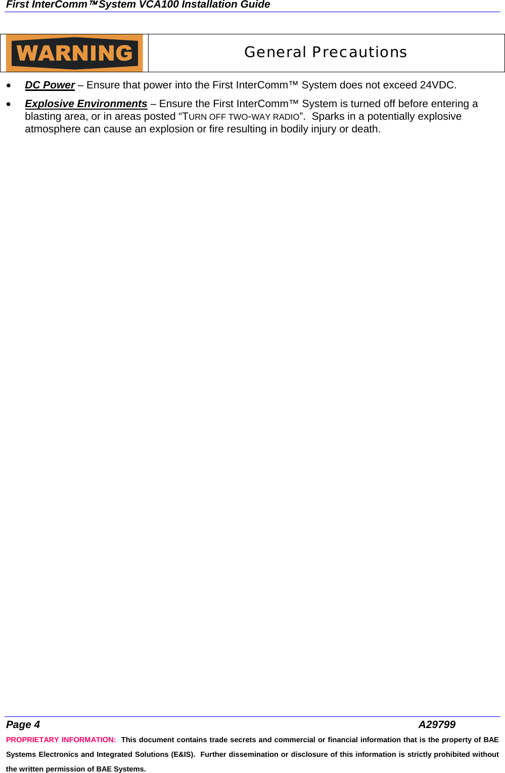
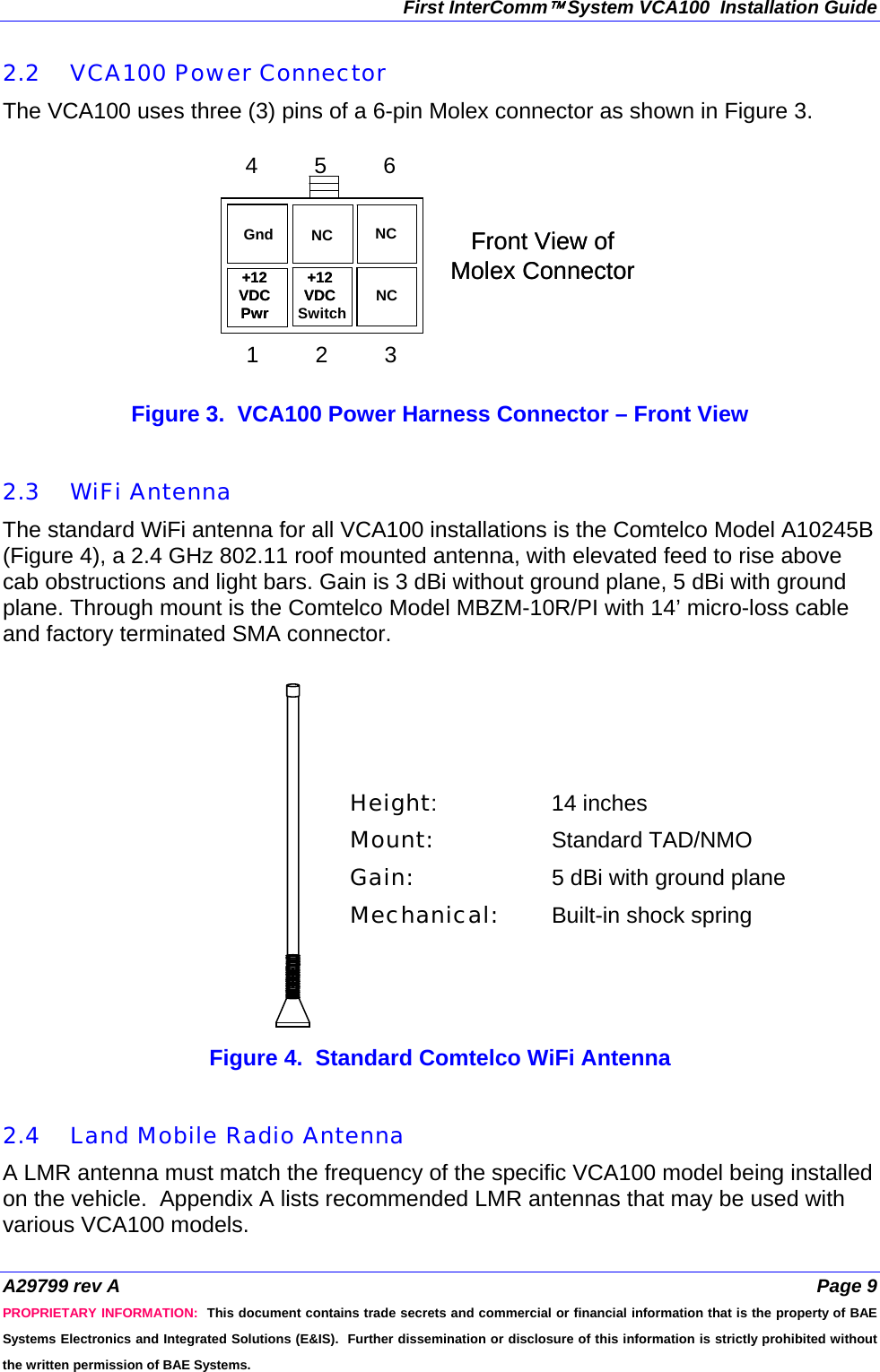
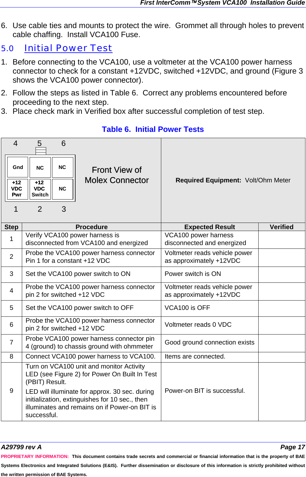
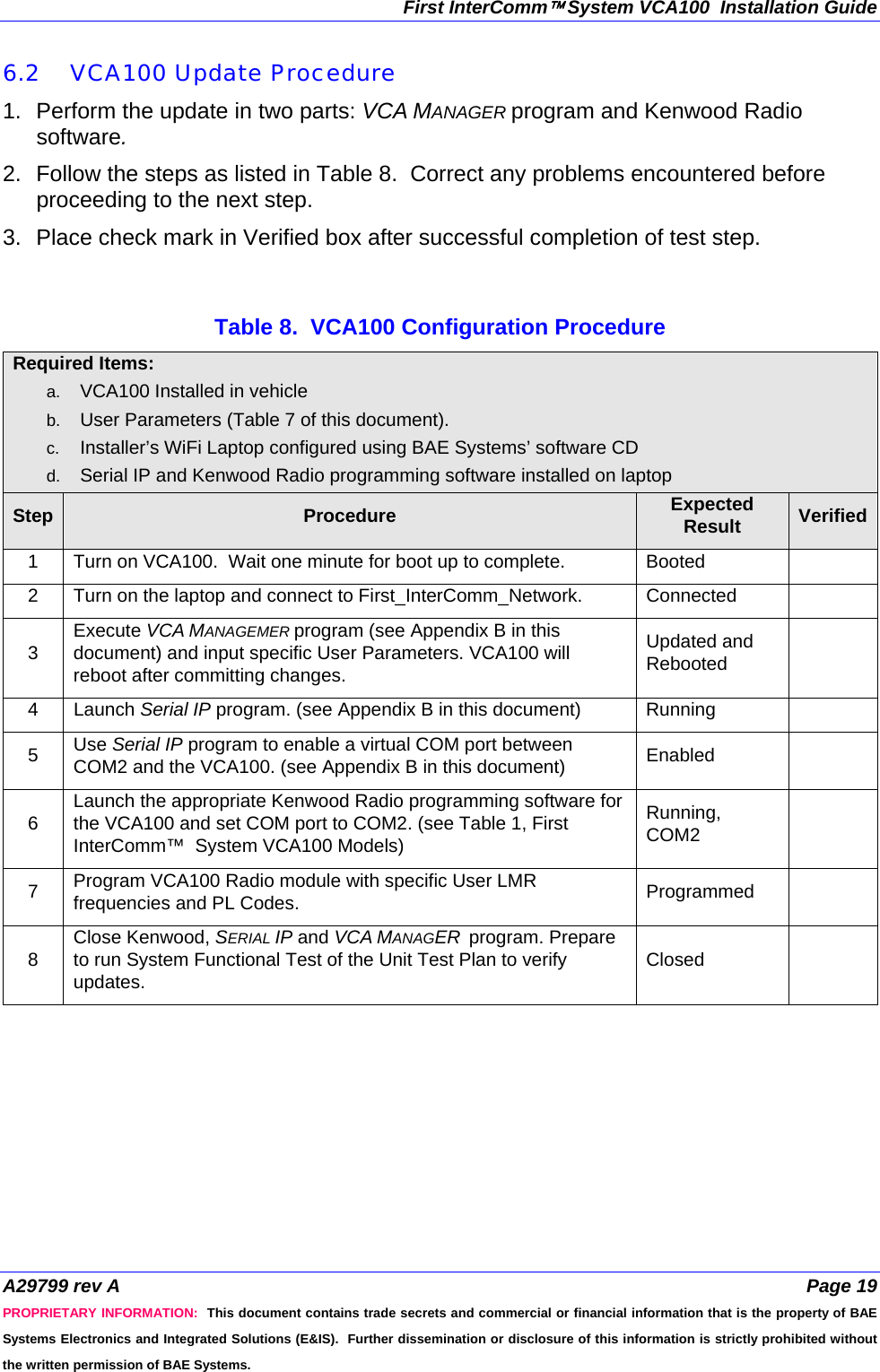
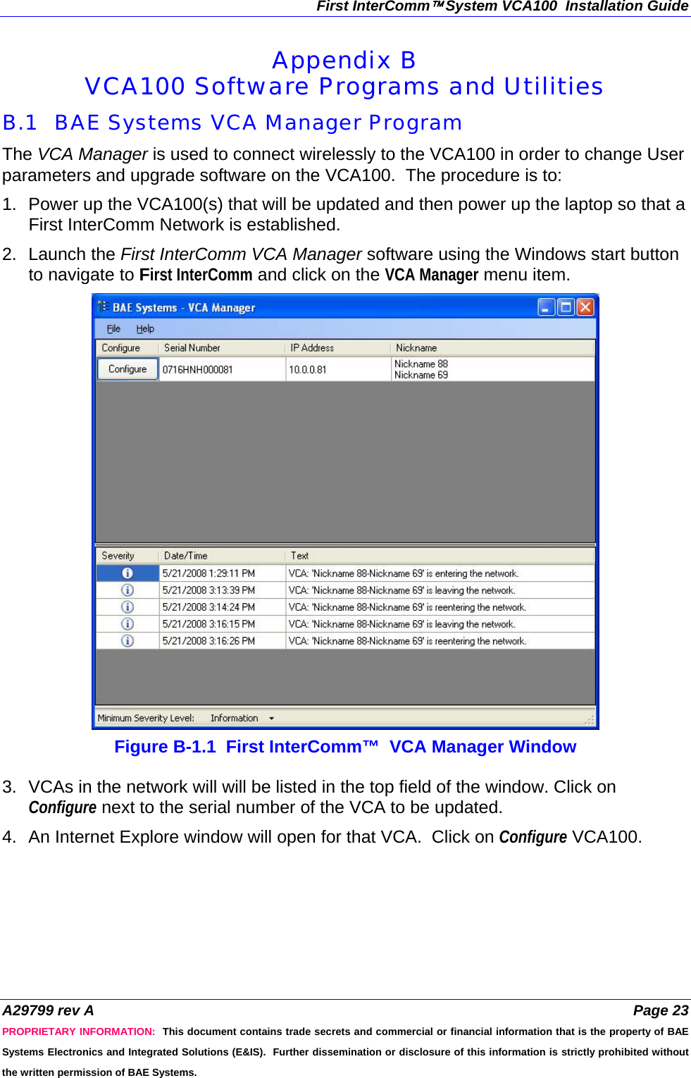
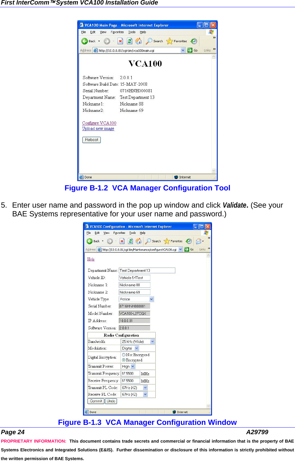
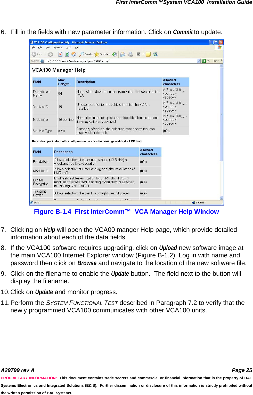
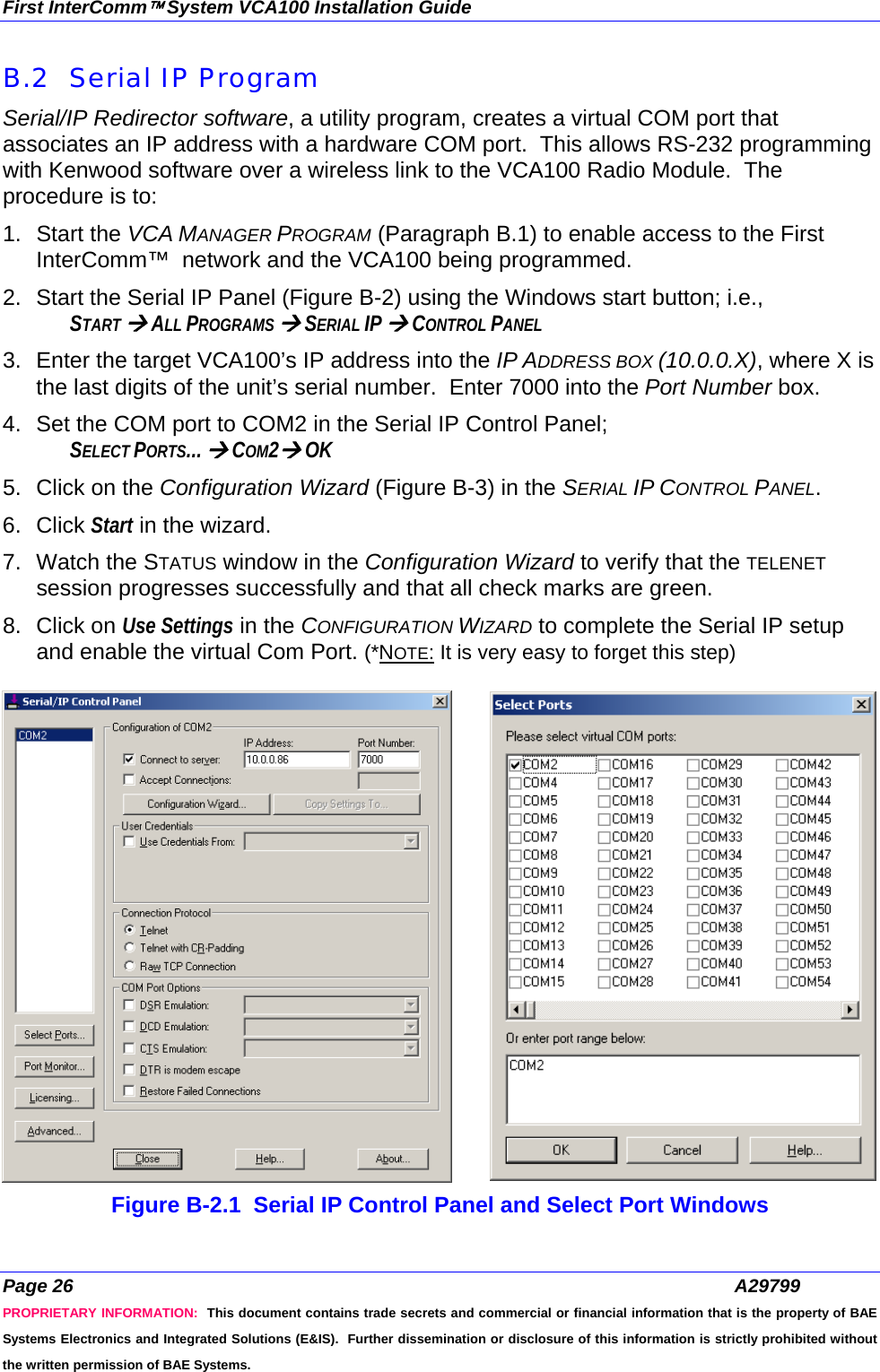
![First InterComm™ System VCA100 Installation Guide Page 18 A29799 PROPRIETARY INFORMATION: This document contains trade secrets and commercial or financial information that is the property of BAE Systems Electronics and Integrated Solutions (E&IS). Further dissemination or disclosure of this information is strictly prohibited without the written permission of BAE Systems. 6.0 Programming Procedure The VCA100 is delivered with operating software but must be updated with user-specific parameters. Programming is done in two parts: • BAE Systems’ supplied VCA MANAGER Program and utilities is used to update the flash or to load new operating software. • Installer supplied Serial/IP COM Port Redirector and Kenwood Radio programming software is used to update the radio module. All programming is done wirelessly by loading the software on an Installer supplied maintenance laptop equipped with a BAE Systems approved wireless network card. 6.1 Preparation 1. Appendix B contains instructions for operating the Serial IP and the VCA MANAGER Programs. See Kenwood documentation for operation of that software. 2. Consult with the end user department and discuss incorporating the VCA100 into their standard operating procedures. 3. Collect and record the required VCA100 User information in Table 7. 4. Provide copies to Customer, BAE Systems, and retain copy for records. Table 7. Required User Information Item Parameter Format User Data 1 Department Name Up to 128 Characters. 2 Vehicle ID Up to 128 Characters. 3 Vehicle Type Icon on WiFi network, e.g., fire, police, ambulance. 4 Nickname Up to 16 Characters 5 LMR Bandwidth Wide (25 kHz) or Narrow (12.5 kHz) 6 LMR Mode Analog or Digital 7 LMR Transmit Power High or Low 8 LMR Transmit Frequency Numeric entry in MHz 9 LMR Receive Frequency Numeric entry in MHz 10 LMR Transmit Private Line Code Frequency or Alphanumeric ID [e.g. 94.8Hz (2A)] 11 LMR Receive Private Line Code Frequency or Alphanumeric ID [e.g. 94.8Hz (2A)] 12 VCA100 ID Serial number on unit](https://usermanual.wiki/BAE-Systems/81FCGX.Installation-guide/User-Guide-1067568-Page-20.png)