BAE Systems V1FCGX-LF First InterComm VCA100 model V1FCGX-LF User Manual Installation guide
BAE Systems First InterComm VCA100 model V1FCGX-LF Installation guide
UserManual.wiki
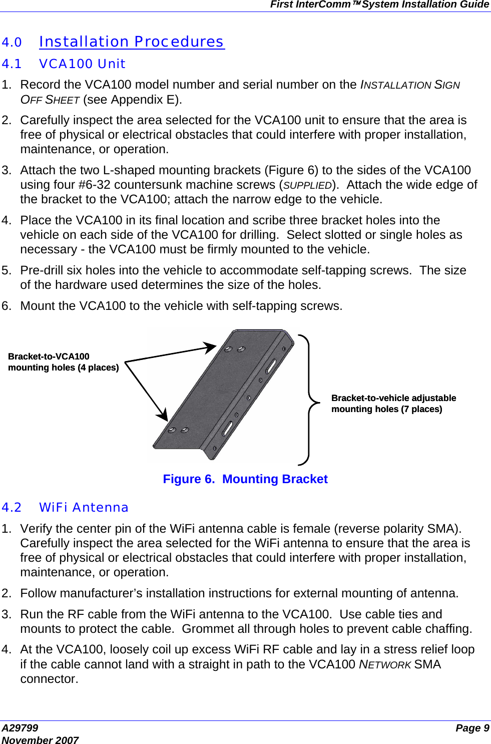
>
BAE Systems
>
V1FCGX-LF User Manual
>
Installation guide
Contents
1.
Installation guide
2.
User guide
Installation guide
Navigation menu
Upload a User Manual
Namespaces
Wiki Guide
HTML
PDF
Info
Views
User Manual
Discussion / Help
Navigation
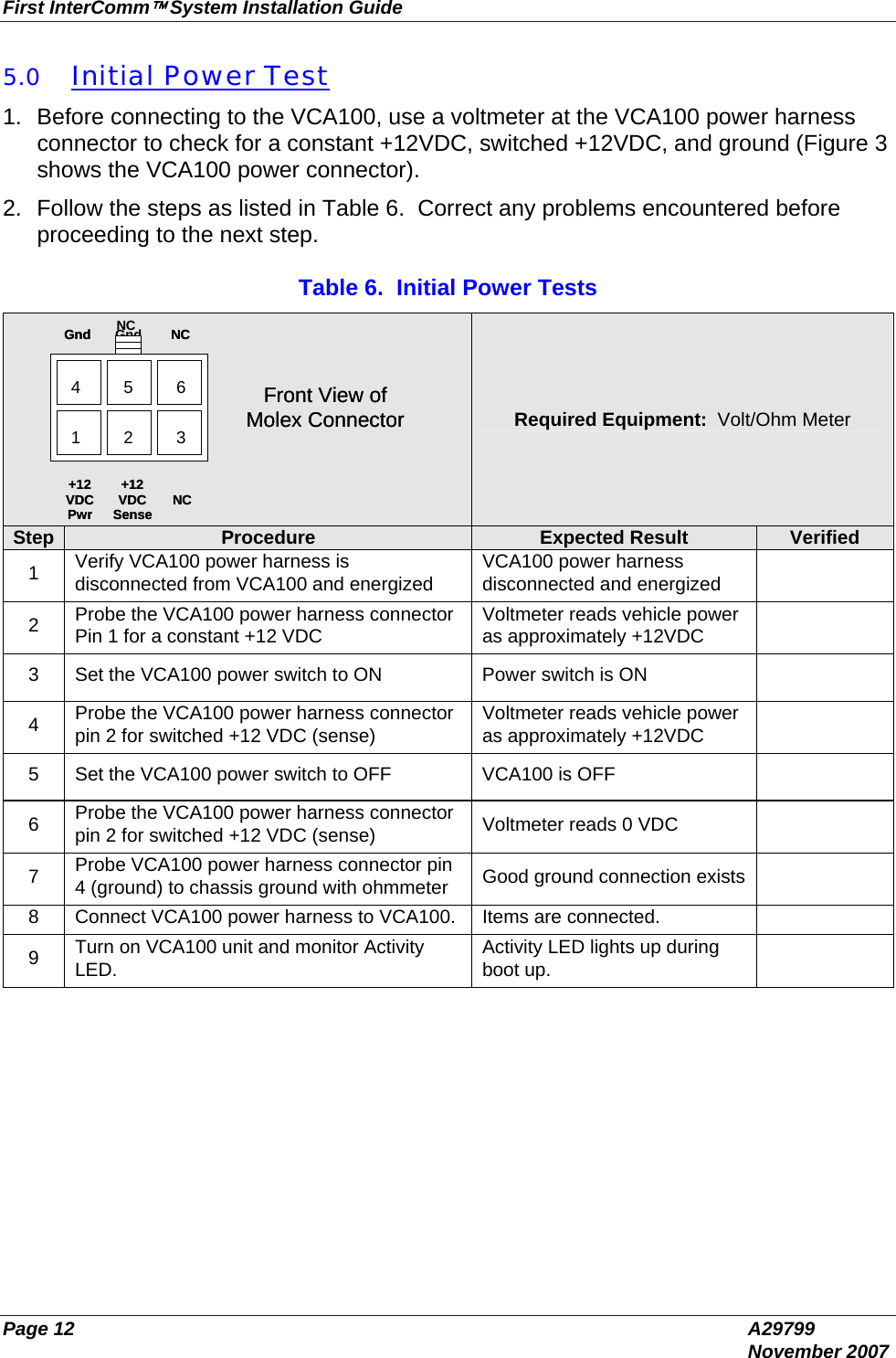
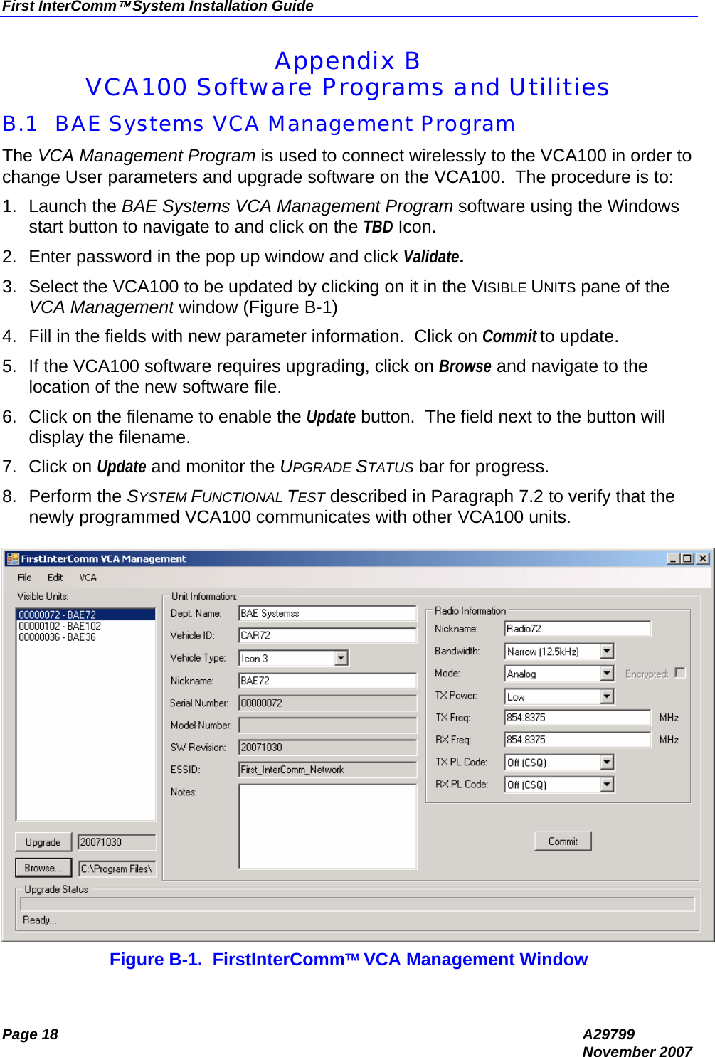
![First InterComm™ System Installation Guide A29799 Page 13 November 2007 6.0 Update User Specific Parameters The VCA100 is delivered with factory-installed default parameters. After vehicle installation, the unit must be updated with user-specific parameters. This programming is done using BAE Systems’ supplied VCA MANAGEMENT PROGRAM and utilities loaded on a maintenance laptop equipped with a Buffalo Technology WLI-CB-G54HP wireless network card. 6.1 Preparation 1. Appendix B contains instructions for operating the Serial IP and the VCA MANAGEMENT PROGRAM. 2. Record the required VCA100 User information in Table 7. This information will be broadcast on the WiFi network. Table 7. Required User Information Item Parameter Format User Data 1 Department Name Up to 128 Characters. 2 Vehicle ID Up to 128 Characters. 3 Vehicle Type Icon on WiFi network pulldown menu; e.g., fire, police, ambulance. 4 Nickname Up to 16 Characters 5 Bandwidth Wide (25 kHz) or Narrow (12.5 kHz) 6 Mode Analog or Digital, pulldown menu 7 Transmit Power High or Low, pulldown menu 8 Transmit Frequency Numeric entry in MHz 9 Receive Frequency Numeric entry in MHz 10 Transmit Private Line Code Frequency or Alphanumeric [e.g. 94.8Hz (2A)], Pulldown menu 11 Receive Private Line Code Frequency or Alphanumeric [e.g. 94.8Hz (2A)], Pulldown menu 12 VCA100 ID Serial number on unit](https://usermanual.wiki/BAE-Systems/V1FCGX-LF.Installation-guide/User-Guide-873621-Page-23.png)