BAOLONG AUTOMOTIVE TPMSIDBOX ID BOX User Manual TIRE PRESSURE MONITORING SYSTEM
SHANGHAI BAOLONG AUTOMOTIVE CORPORATION ID BOX TIRE PRESSURE MONITORING SYSTEM
User Manual
AUTO GENUINE PRODUCTS
Application Models: Buses & Trucks & Trailers & OTR
● Your purchase of genuine products from Baolong is greatly appreciated.
● Please read this user’s manual carefully to ensure proper operation.
User’s Manual for TPMS203
The Fifth Edition
Part No.
Ma Sensing
Pressure
Standard Cold
Inflation Pressure
Low Pressure
Warning Limit
High Pressure
Warning Limit
TPMS203
12.8Bar
185PSI
5.0~9.8Bar
72.5~142PSI
20% decrease
from baseline
pressure
30% increase
from baseline
pressure
● For baseline pressure, the value should be set within the range of standard cold inflation
pressure.
● Keep your tyres properly inflated at all times; either under-inflation or over-inflation may
shorten the transmitter’s battery life and cause system malfunction.
Shanghai Baolong Automotive Corporation reserves the right to change the contents of this
manual at any time without notice. The information contained in this manual is proprietary
and must not be reproduced without prior written consent from Shanghai Baolong
Automotive Corporation.
Copyright © 2012 Shanghai Baolong Automotive Corporation

ATTENTION
Default values have been assigned to each axle for the following:
Standard Cold Inflation Pressure (SCIP) – you can find on the tyre sidewall
Baseline Pressure – 6Bar / 87PSI (default), can be reset by user according to SCIP
Low Pressure Warning – -20% deviation from baseline pressure
High Pressure Warning – +30% deviation from baseline pressure
High Temperature Warning – Over 80℃ / 176℉
Leakage Warning – Air lose is more than 0.33 Bar / 4.8PSI in 16 seconds
No vehicle ID box and trailer box are provided for buses or straight trucks, so you
can flip over these parts with “×”.
PartⅠ
Part Ⅱ
Part
Ⅲ
Part
Ⅳ
Part
Ⅴ
1.1
1.2
1.3
2.1
2.2
2.3
2.4
Buses
Straight Trucks
×
×
×
×
▲Please read this User’s Manual carefully before using this product.
▲TPMS-203 has been developed specifically to address the challenges of tyre pressure
monitoring on large-scale and multi-wheeled commercial vehicles.
▲TPMS-203 is designed to monitor tyre pressure and temperature. It is not designed to
provide warning of sudden critical tyre damage and blowout caused by external effects.
The driver should react promptly to any warning and correct the problem.
▲Tyres may fail for other reasons except for low pressure or overloading. Always be on
alert for any tyre problems as indicated by unusual noises, vibrations, uneven tread wear,
or bulges on the tyre! If any of these symptoms occur, please have the tyres checked
immediately by a professional!

TABLE OF CONTENTS
Part ⅠINTRODUCTION .......................................................................................................................... 1
1.1 DISPLAY ........................................................................................................................................... 1
1.2 TRAILER BOX .................................................................................................................................... 2
1.3 VEHICLE ID BOX ............................................................................................................................... 2
Part ⅡOPERATION ................................................................................................................................ 2
2.1 GETTING STARTED ............................................................................................................................ 2
2.2 SETTING THE BASELINE PRESSURE .................................................................................................... 3
2.2.1 TRACTOR .................................................................................................................................. 3
2.2.2 TRAILER .................................................................................................................................... 3
2.3 CHECKING TYRE CONDITIONS ............................................................................................................ 4
2.4 SETTING TIME ................................................................................................................................... 5
Part Ⅲ WARNINGS ............................................................................................................................... 6
3.1 LOW PRESSURE WARNING ................................................................................................................ 6
3.2 HIGH PRESSURE WARNING ................................................................................................................ 6
3.3 LEAKAGE WARNING ........................................................................................................................... 6
3.4 HIGH TEMPERATURE WARNING .......................................................................................................... 7
3.5 WARNING OF MULTIPLE AXLES ........................................................................................................... 7
Part Ⅳ TRAILER CHANGE AND REGISTERATION ............................................................................ 8
Part Ⅴ WHEEL ROTATION ................................................................................................................... 8
Part Ⅵ REPLACEMENT OF A DAMAGED TRANSMITTER ................................................................. 9
Part Ⅶ RESTART DISPLAY AND TRAILER BOX ................................................................................. 9
Part Ⅷ PARAMETERS OF THE PRODUCT ........................................................................................ 10
Part Ⅸ TROUBLE SHOOTING ............................................................................................................ 11
Part Ⅹ CERTIFICATES ....................................................................................................................... 12
10.1 FCC AND IC'S AUTHENTICATION ANNOUNCEMENT ........................................................................... 12
10.2 EUROPEAN REGULATIONS ANNOUNCEMENT .................................................................................... 13
10.3 CE DIRECTIVE ANNOUNCEMENT .................................................................................................... 13
Part Ⅺ WARRANTY POLICY .............................................................................................................. 13
1
Part ⅠINTRODUCTION
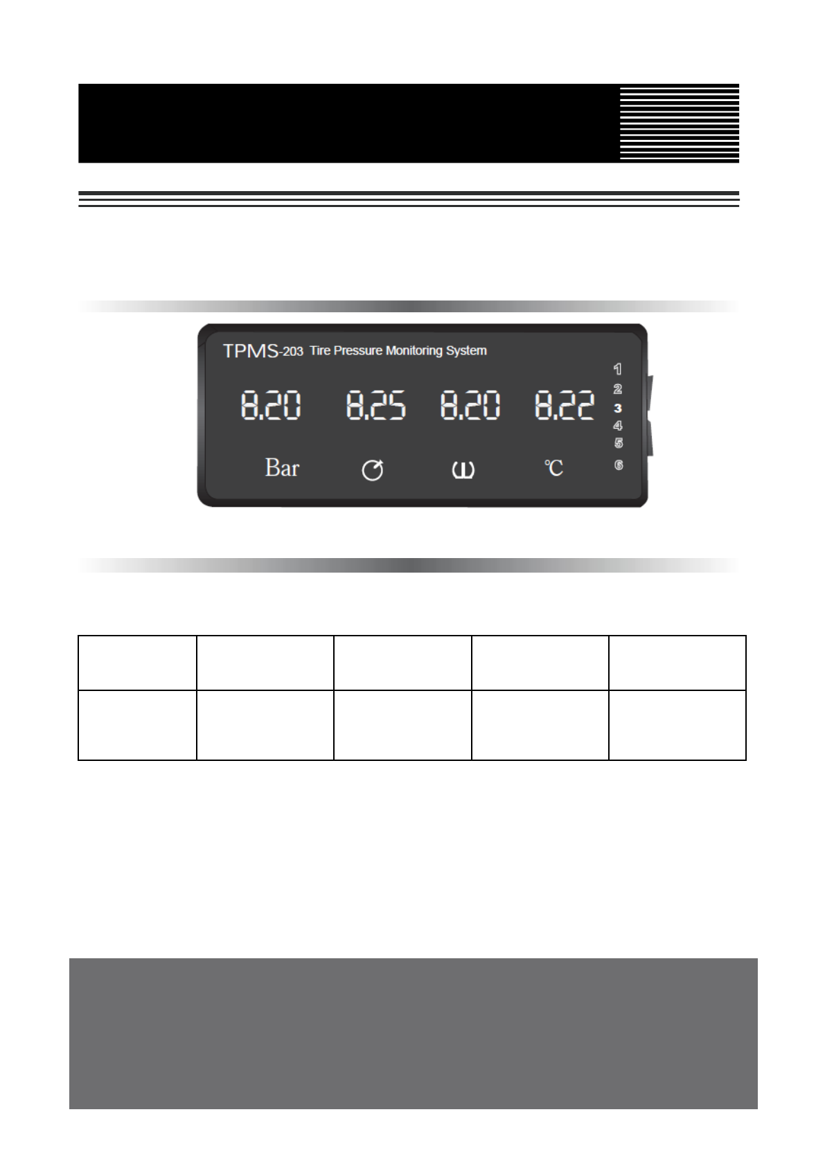
1.1 Display
The display monitors pressure and temperature information of each tyre in a visual form
continuously. This system can monitor up to 6 axles as well as enable baseline pressure
adjustment to suit different tyre specifications.
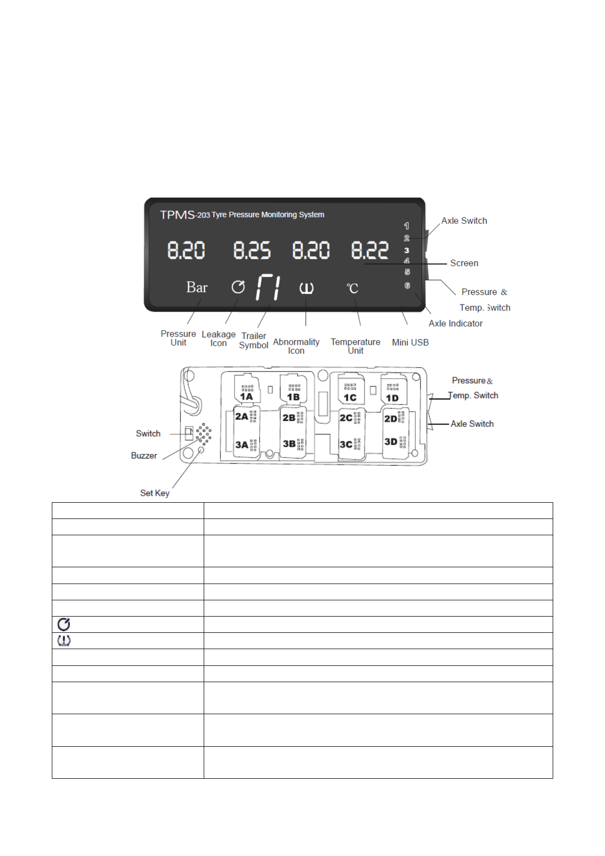
Controls and Indicators
Functions
Axle Switch
Press it to circularly show the data of each axle
Pressure & Temperature
Switch
Press it to scroll through the pressure interface and
temperature interface
Axle Indicator
Display circularly shows the data of six axles
Bar
Pressure unit
℃
Temperature unit
Leakage icon
Abnormality icon: low / high pressure and high temperature
Switch
Turn on or off the display
Buzzer
Give audible alert when the tyre is abnormal
Set Key
Press it to set baseline pressures of truck according to your
tyres’ cold inflation pressure
ID Module Slot
ID modules are used to register Transmitters’ ID code into the
display that will recognize wheel positions
Mini USB Port
To download data from display via RS232 cable. If you need
other data download modes, please consult our distributor
* Back of Display
2
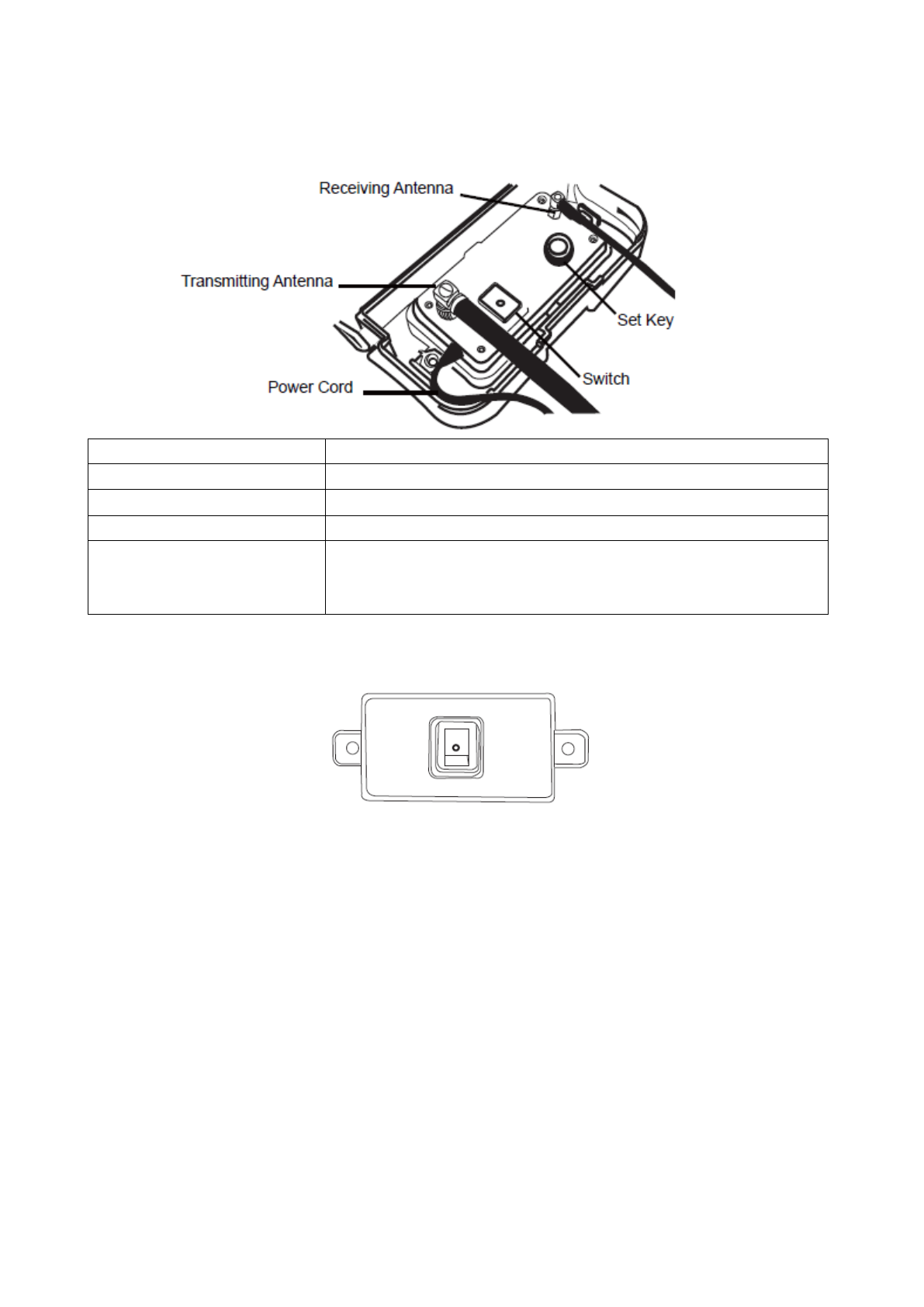
1.2 Trailer Box
The Trailer Box is mounted onto the trailer to read trailer tyres’ information and relay data to
the display wirelessly.
Controls and Indicators
Functions
Receiving Antenna
Collect trailer tyres’ information
Transmitting Antenna
Send trailer tyres’ information to display wirelessly
Switch
Turn on or off the trailer box
Set Key
1) Press it for 8 seconds (red light) to set baseline
pressures of trailer.
2) Press it for 4 seconds (green light) to register the trailer.
1.3 Vehicle ID Box
The Vehicle ID Box is powered by a lithium battery and installed on the tractor. Distance
between Trailer Box and its corresponding Vehicle ID Box should be no more than 1 meter,
to allow them to communicate.
Part ⅡOPERATION
2.1 Getting Started
For tractor with trailer: firstly turn on the display and trailer box, then register trailer into
display (Refer to Part Ⅳ) and set the baseline pressure for each axle.
For bus / straight truck / OTR: firstly turn on the display, then set the baseline pressure for
each axle.
The screen will show “000” until the data from the transmitters are received. When the data

3
from all transmitters has been received, the display will show the data on the screen until a
warning condition is detected.
NOTE: Before doing the following operations, please ensure that ID modules are plugged.
2.2 Setting the Baseline Pressure
The baseline pressure has been set in the factory at 6 Bar (87PSI) for all wheel positions.
We recommend that you set the baseline pressure at the standard cold inflation pressure
recommended by the tyre manufacturer.
NOTE: It’s necessary to set baseline pressure in the following conditions:
1. First installation
2. Wheel Rotation
3. Replacement of transmitters and ID modules.
2.2.1 Tractor
1. Inflate all tyres’ pressures to their standard cold inflation pressure.
2. Press the Set Key on the back of the display quickly to check the baseline pressure set
by manufacturer (6 Bar/87 PSI).
3. Press the Set Key on the display for 5 seconds, you will hear a “Di” sound, all backlights
will flash and then the screens will show “000”. It means the Trailer Box has entered setting
baseline pressure mode.
4. For each tyre, the first pressure value received will be saved as the new baseline
pressure automatically.
2.2.2 Trailer
1. Inflate all trailer tyres’ pressures to the standard cold inflation pressure.
2. Keep the switch on the Trailer Box On.
3. Keep pressing the SET Key for 8 seconds, the light turns red, it means the Trailer Box
has entered setting baseline pressure mode.
NOTE: During the period, the LED light will turn green at first, entering registration mode.
Please keep pressing until the light turns red.
4. For each tyre, the first pressure value received will be saved as the new baseline
4
pressure automatically. The Trailer Box will exit setting baseline pressure mode
automatically when signal from all trailer transmitters are received.
NOTE: After the display has received all transmitters’ pressure value, you can press the
SET Key on the display to look up all tyres’ baseline pressures, axle by axle.
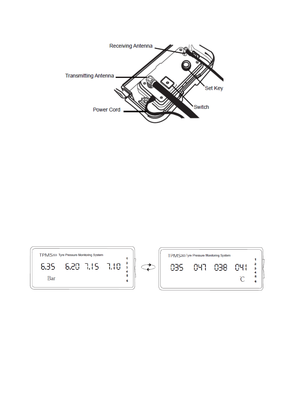
2.3 Checking Tyre Conditions
1. After data from all transmitters is received, the display will show each axle’s data for 5
seconds and automatically shift to next axle when all tyres are normal. You can also press
the Axle Switch to look up tyre data axle by axle quickly.
2. The display keeps showing the axle that has an abnormal warning.
3. If the pressure warning and temperature warning exist in the same axle, the display will
only show the pressure warning of this axle. You can press Pressure & Temperature
Switch to look up temperature interface.
Pressure Interface Temperature Interface
4. If no signal or data is received for 20 minutes, dashes "---" will show on the display.
5
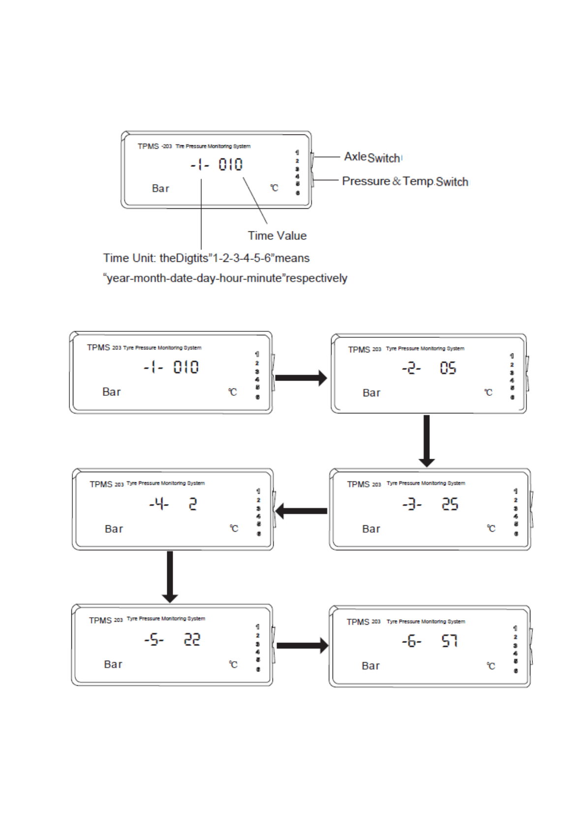
2.4 Setting Time
We have set the GMT +8 as default, please reset if needed.
1. Press Axle Switch for 8 seconds to get into Time Setting Mode and you will hear a “DI”
sound.
2. Press Axle Switch swiftly to look up the time “year-month-date-day-hour-minute” value
circularly. The following time is 22:57, Tuesday, May 25, 2010.
3. Press Pressure & Temp. Switch to change the time value.
4. You must press Axle Switch for 8 seconds to exit time setting mode, if not, the time
setting will take effect. A “DI” sound means time setting has been completed.
6
Part Ⅲ WARNINGS
NOTE: Warning indicates that you are operating your vehicle in a dangerous
condition. When the abnormality icon illuminates, STOP AND CHECK your
tyre(s) as soon as possible and inflate them to the proper pressure.
The system has five types of warning modes:
● 20% below the baseline pressure for the Low Pressure Warning;
● 30% above the baseline pressure for the High Pressure Warning;
● Over 0.33 Bar / 4.8PSI pressure loss in 16 seconds for the Leakage Warning;
● Temperature in the tyre is over 80℃ (176℉) for the High Pressure Warning;
● If no signal or data is received for 20 minutes, dashes "---" will show on the display.
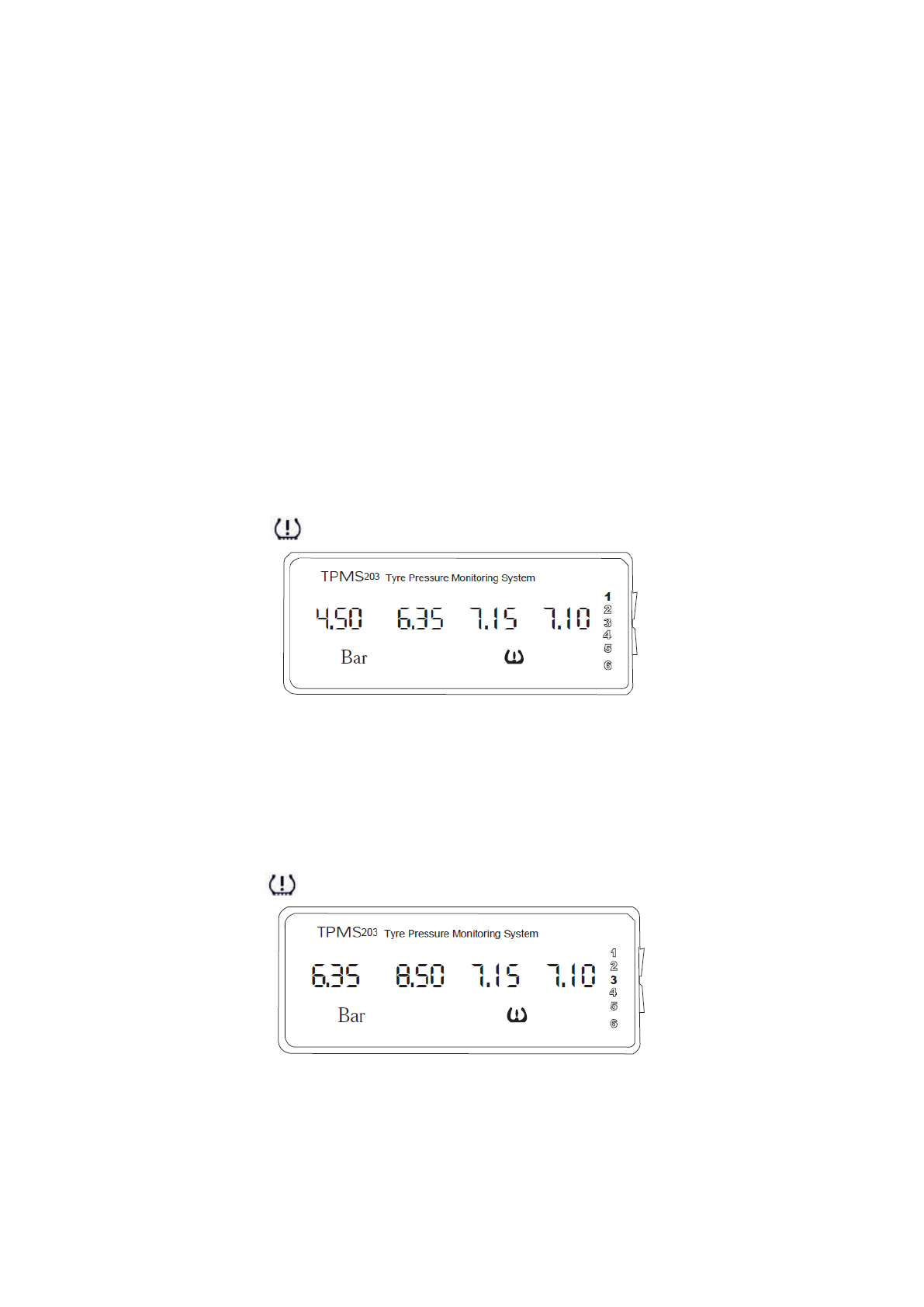
3.1 Low Pressure Warning
When current pressure in the tyre is 20% lower than baseline pressure:
① Display shows the pressure of axle with abnormal tyre; ② Warning sound “Di-Di-Di” ;
③ Abnormality icon “ ” appears; ④ The value of abnormal tyre position flashes.
The figure above shows “1A” tyre is under-inflated.
3.2 High Pressure Warning
When current pressure in the tyre is 30% higher than baseline pressure:
① Display shows the pressure of axle with abnormal tyre; ② Warning sound “Di-Di-Di”;
③ Abnormality icon “ ” appears; ④ The value of the abnormal tyre flashes.
The figure above shows “3B” tyre is over-inflated.
3.3 Leakage Warning
If over 0.33 Bar / 4.8PSI pressure loss in 16 seconds:
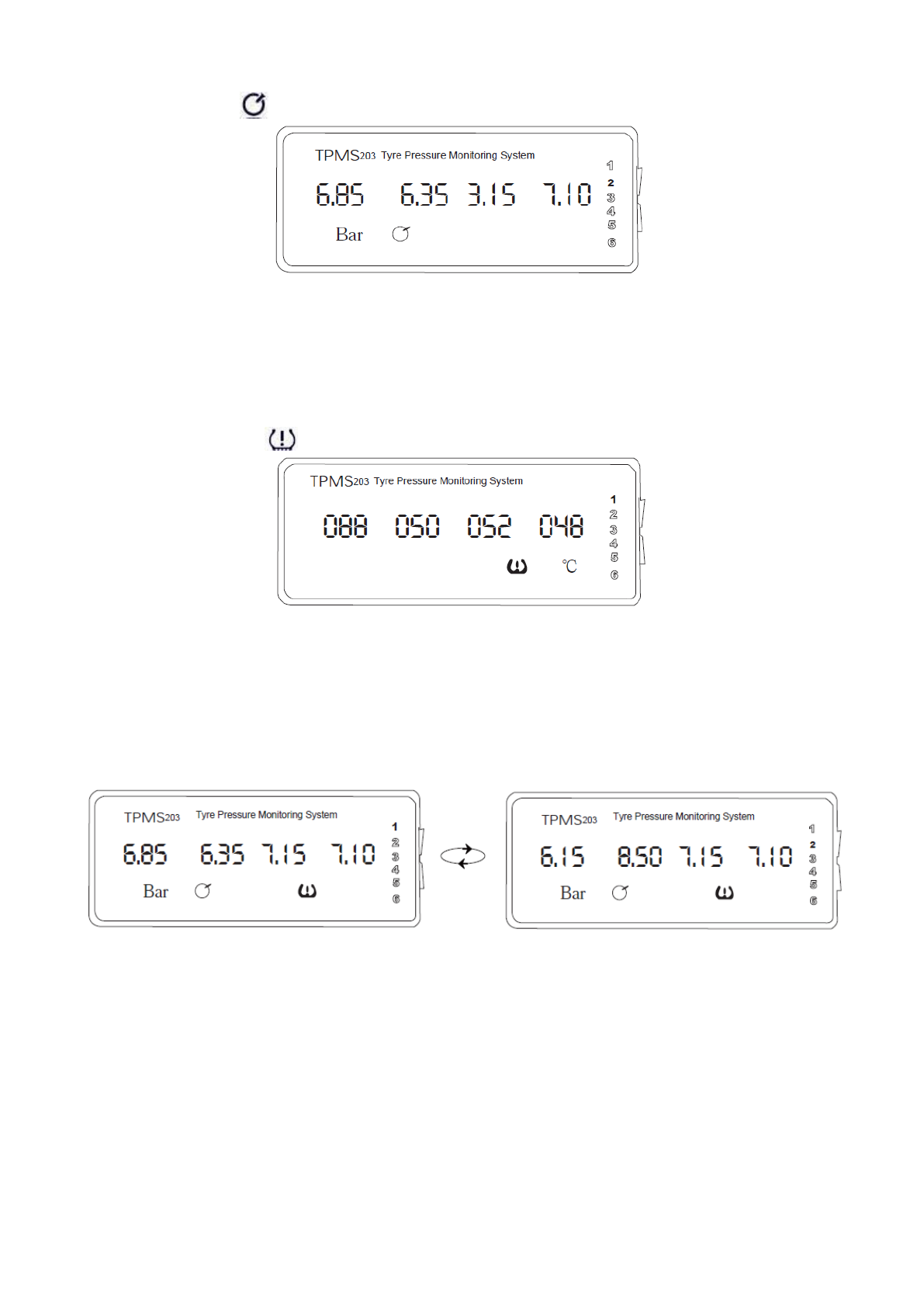
7
① Display shows the pressure of axle with abnormal tyre; ② Warning sound “Di-Di”;
③ Leakage icon “ ” appears; ④ The value of abnormal tyre position flashes.
The figure 6.85 is flashing, that means “2A” tyre is leaking.
3.4 High Temperature Warning
When temperature inside tyre is higher than 80℃ (176℉):
① Display shows the temperature of axle with abnormal tyre; ② Warning sound “Di-Di-Di”;
③ Abnormality icon “ ” appears; ④ The value of abnormal tyre position flashes.
The figure above shows “1A” tyre is over-heating.
3.5 Warning of Multiple Axles
For example, when tyres on two axles are under abnormal conditions, the display will show
both axles circularly at an interval of 5 seconds.
The figure above shows “1A” tyre is leaking and “2B” tyre is over-inflated. The display just
shows axle 1 and axle 2 automatically and circularly until the problems are corrected.
8
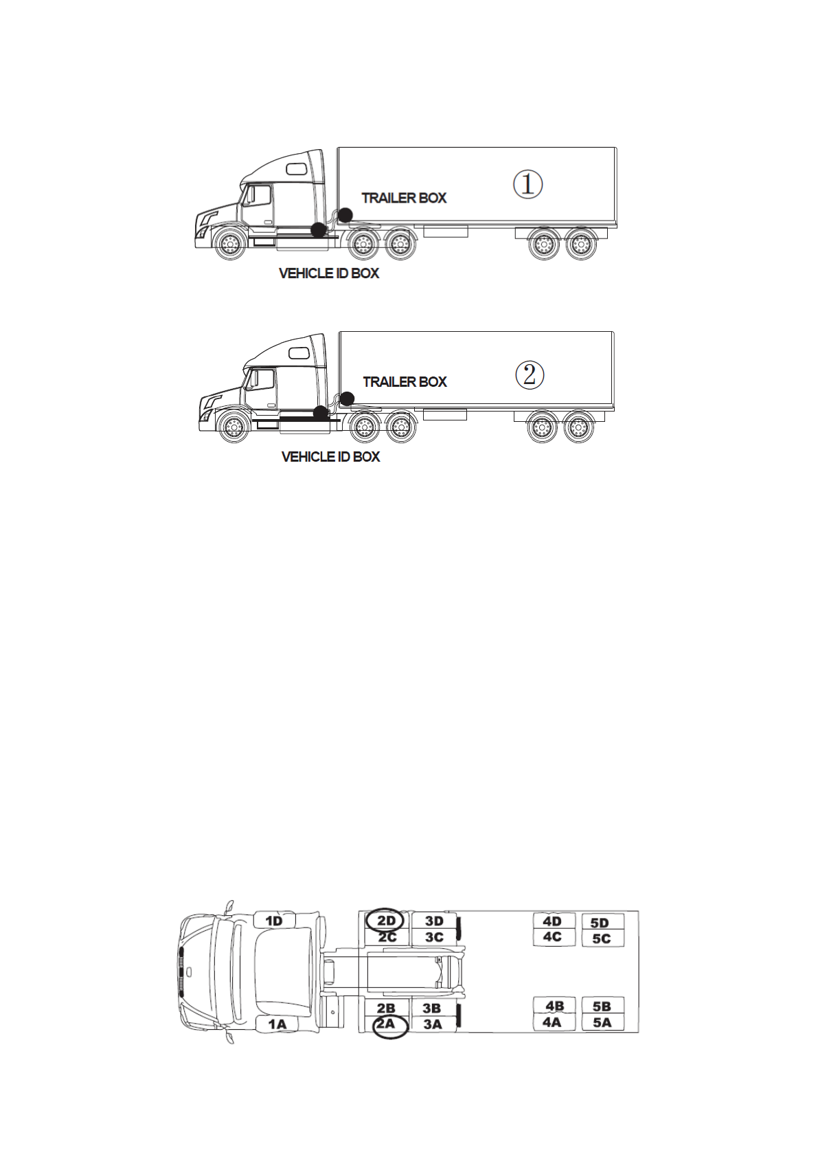
Part Ⅳ TRAILER CHANGE AND REGISTERATION
1. Turn off the trailer box on trailer ①, disconnect the tractor and trailer ①.
2. Connect the trailer ② with tractor.
3. Register trailer ②
Registration between Trailer Box and Vehicle ID Box can be automatically established.
NOTE: During the automatic registration, if the Trailer Box light remains green and does not
turn off, please also try manual registration as below.
1) Turn on the Trailer Box, and the indicator light becomes green. The Trailer Box goes into
registration mode.
2) Turn on the Vehicle ID Box on tractor, which will send out its vehicle ID number
immediately.
3) Trailer Box receives the ID number and remembers it. The indicator light blacks out
simultaneously. The registration is finished.
4) Restart the display.
Part Ⅴ WHEEL ROTATION
When you change wheel position, change corresponding ID modules’ position on the back
of the display and trailer box, and then restart the display and trailer box.
Take 18-wheel vehicle for example.
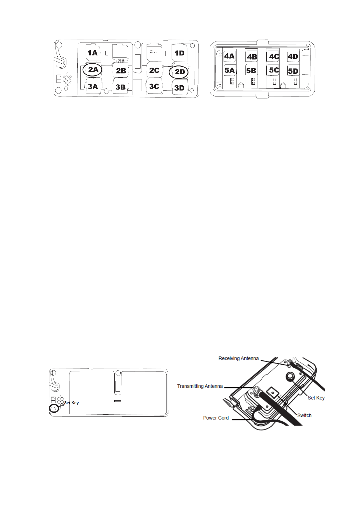
9
Rotate the wheels between position “2A” and “2D”
* Back of Display * Back of Trailer Box
Change their corresponding ID modules’ position, restart display and trailer box
Part Ⅵ REPLACEMENT OF A DAMAGED TRANSMITTER
After replacing the damaged transmitter, you should also replace its ID module.
1. Replace the malfunctioned transmitter
2. Replace the corresponding ID module
3. Restart display and reset baseline pressure
NOTE: If you have a blank ID module, you can use the TPMS Smart Tool to write ID code
into it (Refer to the manual of TPMS Smart Tool).
Part Ⅶ RESTART DISPLAY AND TRAILER BOX
The system has to be restarted to re-identify the tyre ID in the following situation(s):
1. Wheel rotation;
2. Replacement of transmitter & ID module;
3. Trailer change.
To restart the system, turn off the Switch on the display and/or the Trailer Box and then turn
them on again.
Turn off and turn back on to restart the display Turn off and turn back on to restart the Trailer Box

10
Part Ⅷ PARAMETERS OF THE PRODUCT
Display
Power Consumption: 360 mW (Regular); 1200mW (Max)
Power Supply: DC 12/24 Volt
Weight: 231g (8.15 oz.)
Dimensions: 15.5 x 6.2 x 2.3 cm (6.1 x 2.4 x 0.9 inch)
Operating Temperature Range: -40℃ to 85℃ (-40℉ to 185℉)
Pressure Resolution: 0.01Bar (0.1PSI)
Temperature Resolution: 1℃ (1℉)
Transmitter
Weight: 78g (2.47oz.)
Dimensions: 8.3 x 3.1 x 2.5 cm (3.27x1.22x0.98 inch)
Operating Temperature Range: -40℃ to 85℃ (-40℉ to 185℉)
* -40 ℃ to 125 ℃ (-40℉ to 257℉) available upon request.
Pressure Accuracy: ±0.25Bar / ±3.6PSI (at 0℃~50℃)
±0.44Bar / ±6.3PSI (at -40℃~0℃ and 50℃~85℃)
Temperature Accuracy: ±3℃ / ±5℉ (at 0℃~50℃)
±5℃ / ±9℉ (at -40℃~0℃ and 50℃~85℃)
Battery Life: 5 years
Maximum Range: 12.8Bar (185PSI)
Frequency: 433.92MHz

11
Part Ⅸ TROUBLE SHOOTING
Problems
Possible Reasons
Solutions
Both pressure value and
temperature value of all tyres are
"000" shown on the display
Problems of antenna
connection
Check antenna connection
The antenna is damaged
(if all transmitters are well)
Replace antenna
Display malfunction
Use a pair of transmitter & ID
module and TPMS Smart Tool to
confirm. If it doesn’t work, replace it
The pressure and temperature
values are ”000” at some
transmitter positions
(After start the display)
Problem of transmitter
Use TPMS Smart Tool to check it
Problems of ID module
Pull out the ID module and re-plug
in, then restart the display.
If problem still exist, pull out the ID
module and plug in other ID module
position, then restart the display.
If problem still exist, replace the ID
module, then restart the display
The pressure value is “000”, but
temperature value is normal.
Transmitter is damaged
Replace the transmitter
No values shown on the display
and all icon indicators don’t
shine
Display is turned off
Turn on Switch on the back of
display
Power cord is not properly
installed
Check power cord connection
The display is damaged
Replace display
“no id” show on display
ID modules not plugged in
Plug in ID module
Dash “- - -”shows on the display
(When the data transmission
was interrupted)
System failure
Restart the system
Surrounding interference
Move to another place
Problem of transmitter
Use TPMS Smart Tool to check it
Problems of ID module
Pull out the ID module and re-plug in,
then restart the system. If problem
still exist, pull out the ID module and
plug in other ID module position, then
restart the system. If problem still
exist, replace the ID module
000 shown on the display after a
transmitter replacement.
The ID number for the new
transmitter is not programmed
into the display
Replace the old ID module with a new
one. Restart the system and set
baseline pressure
Baseline pressure not set
Set baseline pressure
(High or low) Pressure Warning
at more or all transmitter
positions after installation
Baseline pressure not set
Set up the baseline pressure for each
axle
The buzzer is continuously
beeping and nothing shown on
the display
The display does not work
Replace the display
After the trailer is disconnected
with the tractor, the trailer's data
still shows on the display.
Wait for 10 minutes
The trailer’s data cannot be
shown on display
Display does not match with
Vehicle ID Box
Make sure Display and Vehicle ID
Box has the same ID number
Trailer registration failed
Do trailer registration again
Trailer Box malfunction
Replace Trailer Box, and do
registration again
Vehicle ID Box malfunction
Replace Vehicle ID Box and Display,
and do registration again

12
Part Ⅹ CERTIFICATES
10.1 FCC and IC's Authentication Announcement
This device has been tested and found compliance with applicable the technical standards
of FCC Rules: 1) FCC PART 15C; 2) ANSI C63.4:2003; and also those of IC rules: 1)
RSS210 Issue 8; 2) RSSGEN Issue 3; 3) ANSI C63.4:2003. Operation is subject to the
following two conditions: (1) this device may not cause harmful interference, and (2) this
device must accept any interference received, including interference that may cause
undesired operation.
The applicable standards of FCC and IC rules are designed to provide reasonable
protection against harmful interference in a residential installation. This equipment, if not
installed and used in accordance with the instructions, may cause harmful interference to
radio communications. However, there is no guarantee that interference will not occur in a
particular installation. You can test that if this equipment does cause harmful interference to
radio or television reception by turning the equipment off and on.
Caution content: changes or modifications not expressly approved by the party responsible
for compliance could void the user's authority to operate the equipment.
ISED Statement
‐ English: This device complies with Industry Canada license‐exempt RSS standard(s).
Operation is subject to the following two conditions: (1) This device may not cause interfer
ence, and (2) This device must accept any interference, including interference that may ca
use undesired operation of the device.The digital apparatus complies with Canadian CAN I
CES‐3 (B)/NMB‐3(B).
‐ French:Le présentappareilestconforme aux CNR d'Industrie Canada applicables aux ap
pareils
radio exempts de licence. L'exploitationestautorisée aux deux conditions suivantes: (1) l'ap
pareil ne doit pas produire de brouillage, et (2) l'utilisateur de l'appareildoit accepter tout br
ouillageradioélectriquesubi, mêmesi le brouillageest susceptible d'encompromettre le fonct
ionnement.
This radio transmitter (ISED certification number: 11852A-TPMSIDBOX) has been
approved by Industry Canada to operate with theantenna types listed with the maximum
permissible gain indicated. Antenna types not included in this list, having a gain greater
than the maximum gain indicated for that type, are strictly prohibited for use with thisdevice.
Le présentémetteur radio (ISED certification number: 11852A-TPMSIDBOX) aétéapprouvé
par Industrie Canada pour fonctionner avecles types d'antenneénumérés ci-dessous et
ayant un gain admissible maximal. Les types d'antenne non inclusdanscetteliste, etdont le
gain estsupérieur au gain maximal indiqué, sontstrictementinterdits pour l'exploitation de
l'émetteur.
Radiation Exposure Statement

13
This equipment complies with Canada radiation exposure limits set forth for an uncontrolled
environment.
Déclaration d'exposition aux radiations
Cetéquipementestconforme Canada limitesd'exposition aux radiations dans un environnement non
contrôlé.
10.2 European Regulations Announcement
This device complies with all European Electromagnetic compatibility regulations
(2009/19/EC). The equipment has been tested and found to comply with the above
regulations, and in addition it meets the requirements for low powered transmitters /
receivers as defined by the relevant radio approval authority. The regulations are designed
to provide reasonable protection against harmful interference or susceptibility.
10.3 CE Directive Announcement
This device complies with the essential protection requirements of Council Directive
89/336/EEC on the approximation of the law of the Member states relating to
electromagnetic compatibility. Operation is subject to the following two conditions: (1) this
device may not cause harmful interference, and (2) this device can accept any interference
received, including interference that may cause undesired operation.
Part Ⅺ WARRANTY POLICY
Warranty Statement
Shanghai Baolong Automotive Corporation (“BAOLONG”) warrants to end user of its
products specified below that its products are free from defects in material and
workmanship under normal use and service for the applicable warranty period as described
in the Warranty Period section of this Policy. Subject to the conditions and limitations set
forth below, BAOLONG will, at its option, either repair or replace any part of its products that
proved defective by reason of improper workmanship or materials. Repaired parts or
replacement products will be either new or refurbished to be functionally equivalent to new.
If BAOLONG is unable to repair or replace the product, it will refund the current value of the
product at the time the warranty claim is made.
Limitation of Liability
It does not cover any damage to this product that results from improper installation,
accident, abuse, misuse, natural disaster, insufficient or excessive electrical supply,
abnormal mechanical or environmental conditions, or any unauthorized disassembly, repair,
or modification. This limited warranty also does not apply to any product on which the
original identification information has been altered, obliterated or removed, has been sold
as second-hand.
Products are considered to be monitoring devices and are not to be considered as safety

14
devices. This limited warranty covers only repair, replacement or refund for defective
BAOLONG products. All other express or implied warranties, liability for incidental, special,
consequential or any other damages including but not limited to, economic loss, lost
revenue, lost profits, or loss of use or damage to other property, hereby are expressly
disclaimed regardless of whether they were reasonably foreseeable, or whether seller had
knowledge that they could occur.
Responsibility
The end user will provide the dealer with dated proof of purchase and access to claimed
parts for return. BAOLONG warranty will be honored by the authorized distributor or dealer
from which the Product was purchased. Authorized dealers are to contact their regional
BAOLONG distributor with warranty claims and questions. Dealers will provide distributor
with dated proof of purchase, claimed parts for return upon request, and a completed
Warranty Claim Form (Appendix 1). The distributor will be responsible for administering the
warranty as per the claims procedure.
NOTE: Any product returned for warranty without a completed Warranty
Claim Form (Appendix 1) will be excluded without consideration.
Exclusive Agreement
This Limited Warranty is a complete and exclusive statement which applies to the
BAOLONG TPMS. There are no express or implied warranties beyond those expressly
stated above. No employee, agent, distributor, dealer or other person is authorized to give
any warranties on behalf of BAOLONG, except as authorized just in writing.
Warranty Scope: Display, transmitter and strap, vehicle ID box, trailer box and ID module.
Warranty Period
The term of BAOLONG warranty for its products is warranted against defects in material or
workmanship that result in a product failure under normal use during a period of 12 months
following the date of purchase by the end user and unlimited mileage. Dated proof of
purchase is required. If you do not have a valid proof of purchase, the warranty period will
be measured from the date of sale from BAOLONG to the authorized BAOLONG Distributor
from whom you purchase.
The term of BAOLONG warranty for its products is warranted against defects in material or
workmanship that result in a product failure under normal use during a period of 12 months
following the date of purchase by the end user and unlimited mileage. Dated proof of
purchase is required. If you do not have a valid proof of purchase, the warranty period will
be measured from the date of sale from BAOLONG to the authorized BAOLONG Distributor
from whom you purchase. If the warranty period specified in local law exceeds the period
given by Baolong, the former will supersede the latter.
Remedy
The exclusive remedy for retail system determined by BAOLONG to be defective within
such period shall, at the sole option of BAOLONG, be
(1) The repair or replacement of such defective product, OR
(2) The refund of the current value (not more than the purchase value) of the product at the
time the warranty claim is made.

15
Products replaced under warranty are covered hereunder by the remaining portion of the
original warranty period or 12 months, whichever is greater.
BAOLONG obligation to satisfy a warranty claim is subject to the following conditions:
(1) Dated proof of purchase is provided
(2) All such claims must be submitted to BAOLONG no later than sixty (60) days from the
date of the failure (the date BAOLONG receives the complaint), and must be accompanied
by a Warranty Claim Form (Appendix 1). No product will be accepted for warranty unless
accompanied by a completed Warranty Claim Form (Appendix 1).
(3) Some pictures of defective product/part are helpful for remedy.
(4) If requested by BAOLONG, the product involved shall be returned, freight prepaid, to
BAOLONG for examination; and
(5) Products shipped to BAOLONG must be properly packaged to prevent damage in
transit.
Claims Procedure
Warranty claims will only be accepted from an authorized BAOLONG distributor. The
following procedure must be followed when making a warranty claim:
1. If you suspect a product defect, contact BAOLONG distributor for assistance in verifying
the problem.
2. If a defect is found, provide BAOLONG distributor with Warranty Claim Form along with
some pictures of defective parts if possible prior to removing suspected warranty parts.
3. BAOLONG distributor will transform the material above by fax or email to BAOLONG
customer service.
4. BAOLONG customer service will gather information and refer the claim to technical
service as required.
5. Technical service will assist in troubleshooting, and subsequently determine whether a
warranty claim is required.
6. If the warranty claim is approved, customer service will issue return authorization to
distributor, who will return the defective products or parts.
7. Product shall be returned, freight prepaid, to BAOLONG along with dated proof of
purchase, some pictures and a completed Warranty Claim Form (Appendix 1) to the
following location:
Shanghai Baolong Automotive Corporation
5500 Shenzhuan Road, Songjiang, Shanghai, 201619, China
8. BAOLONG will ship distributor repaired or new product/part without any charge.
All claims submitted must include:
(1) Dated proof of purchase is provided
(2) All such claims must be submitted to BAOLONG no later than sixty (60) days from the
date of the failure (the date BAOLONG receives the complaint),
(3) A Warranty Claim Form (Appendix 1)
(4) Some pictures of defective product/part are helpful for remedy.
(5) If requested by BAOLONG, the product involved shall be returned, freight prepaid, to
BAOLONG for examination;
BAOLONG reserves the right to reject a warranty claim for any or all of the following
reasons:
(1) Dated proof of purchase is not provided;

16
(2) Claims is submitted to BAOLONG over sixty (60) days from the date of the failure (the
date BAOLONG receives the complaint);
(3) No or incomplete Warranty Claim Form (Appendix 1)
(4) Product was not returned for inspection as requested
(5) Product inspection does not indicate a failure
(6) Failure occurred beyond warranty period
(7) Product damage in transit.
Return Requirements of Defective Parts
Be sure the parts are properly identified and packed
(1) Each part must be accompanied by a completed Warranty Claim Form (Appendix
1). No product will be accepted for warranty without a completed Warranty
Claim Form (Appendix 1).
(2) When shipping parts for several different claims together, do not mix the parts in the
same container, box, etc. This could cause confusion in performing a failure analysis, a
delay in claim processing, and possible rejection of the claim.
(3) Pack the parts carefully to avoid shipping damage which could distort or mask the true
cause of the failure. Parts lost from broken boxes, damaged shipping containers, or
negligence in packaging may result in rejection of the claim.
(4) Corrosion or rust that prevents proper inspection, or prevents identification of the
primary failure, may result in rejection of the claim.
(5) Rejected parts will be returned to distributor at distributor’s expense if the distributor
wishes the parts returned.
(6) Return all parts prepaid to the correct designated location.
This warranty supersedes all past warranties expressed by BAOLONG and may not be
changed, altered or modified in any way except in writing by BAOLONG.
Appendix 1 Warranty Claim Form
Customer:
Distributor:
Product Information
S/N(on top of the display):
Date of Purchase:
Date of Claim:
Vehicle Information
Year: Brand: Model: Mileage:
The Standard Cold Inflation Pressure
Tyres Layout (how many axles, how many tyres on each axle):
Length of Vehicle:
Usage information
Power connection
Cigarette plug Hardwire/battery

17
Did you accelerate the speed from 0 to 25km/h fastly
Yes No
Did you ever change the original transmitter?
Yes No
Did you do tyre repair recently?
Yes No
Detailed Description of Defective Part
What problems happen when driving or stopping? What shows on display? (pressure, temperature
backlight, icon, buzzer)
Frequency of Problem
Rare Very often
Other Description:
Distributor Signature:
Parts Needed to be Replaced (Must be returned to Baolong)
Part Name and S/N Number
Quantity

Shanghai Baolong Automotive Corporation
5500, Shenzhuan Rd., Songjiang, Shanghai 201619, China
Tel.: +86-21-31273333 Fax: +86-21-31190319
E-mail: sbic@chinabaolong.net sbic@baolong.biz
Web: www.baolong.biz
Important
Claim must be submitted within 60 days after failure
Fill out one claim form for each claim
Dated proof of purchase is provided
Some pictures of defective product/part are helpful for remedy.