BARCO AMM213TDS3 LCD Monitor User Manual EMISSION TEST REPORT
Advan Int'l Corp. LCD Monitor EMISSION TEST REPORT
BARCO >
users manual

Test Report No.: GETEC-E3-06-043
FCC Class B Certification
EUT Type: 21” FLAT PANEL MONITOR
APPENDIX G
: USER’S MANUAL
FCC ID: QVXAMM213TDS3

2006/05 www.stryker.com 1000-400-895 A
VISIONELECT
21'' High-Definition
LCD Monitor
REF 240-030-930
User Guide
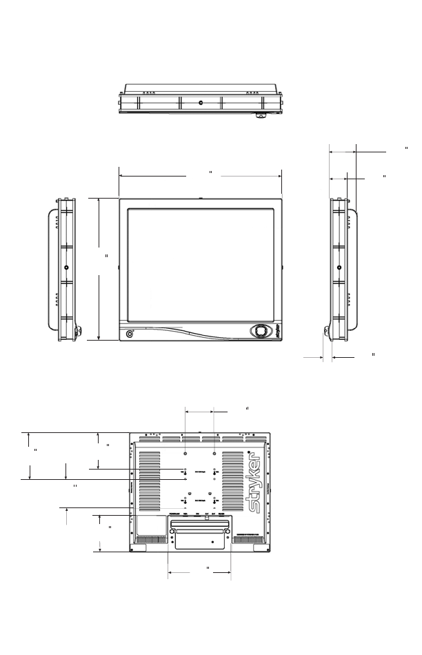
16.42
(417.20 mm)
19.21
(488 mm)
5.05
(128.20 mm)
3.94
(100 mm)
.95
(24.25 mm)
3.15
(80 mm)
2.05
(52 mm)
8.66
(220 mm)
6.23
(163.20 mm)
3.94
(100 mm)
4.99
(127 mm)

1
English
EN
Table of Contents
Warnings and Cautions ......................................................................... 2
Warnings ........................................................................................... 2
Cautions ............................................................................................3
Symbol Definitions ............................................................................ 5
Product Description and Intended Use ............................................... 6
Product Contents .............................................................................. 6
Setting Up the Monitor .......................................................................... 8
System Interconnection .................................................................... 8
Power Connection ............................................................................. 8
Operating the Monitor ........................................................................... 9
Front Panel Controls ......................................................................... 9
Standard On-Screen Display (OSD) Operation ............................... 10
Stryker Camera Preset Modes ........................................................ 10
OSD Function Description .............................................................. 11
Cleaning the Monitor ....................................................................... 12
Troubleshooting .................................................................................. 13
Technical Specifications ..................................................................... 14
Classification and Approvals ........................................................... 17
Electromagnetic Compatibility ........................................................... 16
Warranty ............................................................................................... 22
Service and Claims .............................................................................. 22
Declaration of Conformity .................................................................. 23
2
Warnings and Cautions
Please read this manual and follow its instructions carefully. The words
warning, caution, and note carry special meanings and should be
carefully reviewed:
Warnings
Warning To avoid potential serious injury to the user and the
patient, and/or damage to this device, the user must:
1. Restrict this device to use by, or on the order of, a physician,
because of Federal law (United States of America).
2. Read the operating manual thoroughly and be familiar with its
contents prior to using this equipment.
3. Carefully unpack the unit and check if any damage occurred
during shipment.
4. Test this equipment prior to a surgical procedure. This monitor
was fully tested at the factory before shipment.
5. Do not place the monitor or any other heavy object on the power
cord. Damage to the cable can cause fire or electric shock.
6. Should any solid object or liquid fall into the panel, unplug the unit
and have it checked by qualified personnel before operating it
any further.
7. Unplug the unit if it is not to be used for an extended period of
time. To disconnect the cord, pull it out by the plug. Never pull the
cord itself.
W
arning The personal safety of the patient or physician may be
involved. Disregarding this information could result in
injury to the patient or physician.
W
arning A lightning bolt within a triangle is intended to warn of
the presence of hazardous voltage. Refer all service to
authorized personnel.
C
aution Special service procedures or precautions must be
followed to avoid damaging the instrument.
Note Special information to make maintenance easier or
important information more clear.

3
English
EN
8. To avoid electric shock, avoid removing control unit covers.
9. Do not attempt internal repairs or adjustments not specifically
detailed in this operating manual.
10. Pay close attention to the care and cleaning instructions in this
manual. A deviation may cause damage (refer to the Cleaning
section).
11. Do not sterilize the monitor.
12. Use appropriate caution to prevent contact with fluids, if the unit is
being used with a power supply in patient environments.
Cautions
1. The AC Adapter must be plugged into a grounded power outlet.
2. Use only the proprietary VISIONELECT (model 240-030-930)
power supply (model 240-030-931) for the VISIONELECT (model
240-030-930) monitor. Make a proper connection by ensuring
that the shrink tubing completely secures the connection between
the DC power cord and the extension cord.
3. Grounding reliability can only be achieved when the equipment is
connected to an equipment receptacle labeled “Hospital Only” or
“Hospital Grade.”
4. To connect to an international power supply, use an attachment
plug appropriate for the power outlet.
5. Turn power off when unit is not in use.
6. Remove the power module and connection when transporting the
unit.
7. Save the original carton and associated packing material. They
will be useful should you have to transport or ship the unit.
8. Handle the monitor with care. Do not strike or scratch the screen.
9. Never operate the unit right after having been transported from a
cold location directly to a warm location.
10. Do not expose the monitor to moisture or directly apply liquid
cleaners directly to the screen. Spray the cleaning solution into a
soft cloth and clean gently.
11. Allow adequate air circulation to prevent internal heat buildup.
12. Do not place the unit on surfaces (rugs, blankets, etc.) or near
materials (curtains, draperies) that may block the ventilation slots.
The monitor is cooled by natural convection and has no fan.
13. Do not install the unit near sunlight, excessive dust, mechanical
vibration or shock.
4
14. The unit is designed for operation in a horizontal position. Do not
operate the unit in a vertical position.
15. Keep the unit away from equipment that uses strong magnets
(i.e., large loudspeakers).
16. Do not touch the patient with signal input or output connectors.
Equipment with SIP/SOP connectors should either comply with
IEC 60601-1 and/or IEC 60601-1-1 harmonized national
standards or the combination should be evaluated.
17. CAUTION: Changes or modifications not expressly approved by
the party responsible for compliance could void the user's authority
to operate the equipment.
NOTE : This equipment has been tested and found to comply
with the limit for a Cass B digital device, pursuant to Part 15 of
the FCC Rules. These limits are designed to provide resonable
protection against harmful interference in a residential installation.
This equipment generates, uses and can radiate radio frequency
energy and, if not installed and used in accordance with the
instructions, may cause harmful interference to radio
communications. However, there is no guarantee that
interference will not occur in a particular installation, which can
be determined by turning the equipment off and on, the user is
encourage to try to correct the interference by one or more of
the following measures.
• Reorient or relocate the receiving device.
• Increase the separation distance between the equipment.
• Connect the equipment to an outlet on a circuit different from
that to which the other device(s) are connected.
• Consult the manufacturer or field service technician for help.
18. To ensure electromagnetic compatibility, refer to the
“Electromagnetic Compatibility” section of this manual. The
VISIONELECT (model 240-030-930) monitor must be installed
and operated according to the EMC information provided in this
manual.
The VISIONELECT (model 240-030-930) monitor has been tested under
the UL 60601-1 standard and is UL listed for medical application.
The warranty is void if any of these warnings or cautions are
disregarded.
5
English
EN
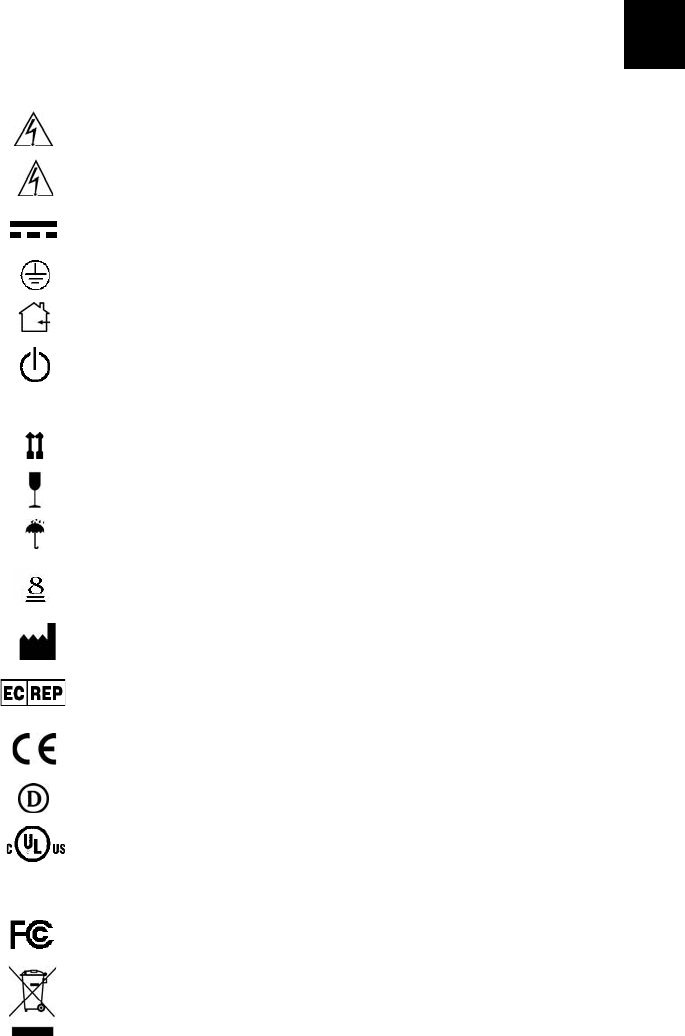
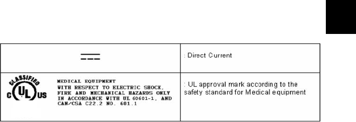
Symbol Definitions
The following symbols appear on the product, its labeling, or the product
packaging. Each symbol carries a special definition, as defined below
Dangerous: High Voltage
Consult accompanying documents.
Direct Current
Indicates protective earth ground.
For indoor use only.
DC power control switch
Serial Number
Top - Bottom
Fragile
Do not get wet
Maximum Stacking
Manufacturer
European Authorized Representative
Indicates proof of conformity to applicable European Economic Community
Council directives and to harmonized standards published in the official journal
of the European Communities.
Tested and certified by DEMKO in accordance with EN 60601-1 and
EN 60601-1-2.
51LJ
Medical Equipment
E215822
Medical Equipment is in accordance with UL 60601-1 and CAN/CSA C22.2 No.
601.1 in regards to electric shock, fire hazards, and mechanical hazards.
Tested to comply with FCC Class B standards.
This symbol indicates that the waste of electrical and electronic equipment
must not be disposed as unsorted municipal waste and must be collected
separately. Please contact the manufacturer or other authorized disposal
company to decommission your equipment.
SN
6
Product Description and
Intended Use
The VISIONELECT (model 240-030-930) 21-Inch High Definition LCD
Monitor is an intelligent, microprocessor-based TFT-LCD monitor
intended for use in endoscopic surgical applications. It has an
ergonomically designed display and is compatible with most analog RGB
(Red, Green, Blue) display standards.
The VISIONELECT (model 240-030-930) monitor has the following
features:
• Advanced Viewing Solution (AVS): A sophisticated filter
extends the viewing angle of the screen image, without
sacrificing contrast ratio and brightness.
• Upgraded video cards or software will not require buying a new
monitor because of the wide auto-scanning compatibility range.
• The internal microprocessor digitally controls auto-scanning, for
horizontal scan frequencies between 31.47 KHz and 78.88 KHz,
and vertical scan frequencies between 50.0 Hz and 85.1 Hz. In
each frequency mode, the microprocessor-based circuitry allows
the monitor to function at the precision of a fixed frequency.
• The resident memory allows for storing factory default settings
and also additional user adjustment parameters.
• The maximum resolution achievable is UXGA (1600 × 1200,
be60Hz), st suited for Stryker cameras.
• The monitor is compliant with the VESA-DPMS power-
management standard. In order to save energy, the monitor
must be connected to a system compliant with the standard.
• The monitor is designed to mount an accessory (such as a
camera or speaker) with a 2 lbs (max) load per hole.
• The monitor is certified by UL International in accordance with
medical standard UL 60601-1. It is also CE marked for sale in
the European Community for integration or use with medical
products. It is certified by DEMKO according to EN 60601-1
and EN 60601-1-2 for sale to the medical market.
Product Contents
1. Carefully unpack the VISIONELECT (model 240-030-930)
monitor. Save the original carton and associated packing
material. They will be useful should you have to transport or ship
the unit.
7
English
EN
2. Check the monitor and its accessories for any damage that may
have occurred during shipping. Immediately report any damage
to the shipping company.
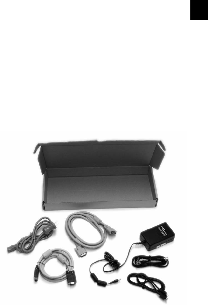
3. Check the contents of the accessories package with the following
list to make sure all components have been included. In addition
to this manual, you should find:
(a) 1 DVI cable
(b) 1 VGA HDDB15 cable
(c) 1 AC adapter (Stryker P/N 240-030-931)
(d) 1 Hospital-grade AC power cord
(e) 4 M4 x 10mm VESA screws (not shown)
(f) 1 BNC cable
(g) 1 S-Video cable
(h) 1 15’ or 75’ extension cable with heat shrink tubing, for
connection to the DC power cord (optional, not shown)
(i) Power supply bracket (optional, not shown)
(a)
(b)
(c)
(d)
(f)
(g)
8
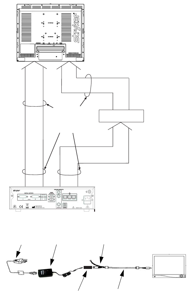
System Interconnection
Power Connection
Video Input Signals
eg:
SDC
SIDNE
VIDEO PRINTER
DVD/VCR
etc...
Video Sources:
Camera (1188 Series,
1088 Series, 988 Series)
Video Peripheral
Signal Output
DVI
RGBHV
S-Video
C-Video
(Model 240-030-930)
VISIONELECT
VISIONELECT
:
Hospital-grade
power cord Power Supply
240-030-931 Ground to
Cart Chassis
Heat-shrink tubing between the
DC power cord and extension cord 240-030-722 or
240-030-932
VISIONELECT
(model 240-030-930)
9
English
EN
Operating the Monitor
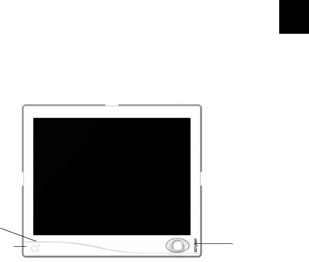
Front Panel Controls
Operate the monitor using the rotary control located on the front panel. A
list of the monitor controls and their functions is provided below.
.
Figure 1: The VISIONELECT LCD Monitor front panel controls.
1. Power LED: Indicates menu current status. Displays green if
monitor is powered on, blinks orange if monitor is in Standby
mode.
2. Power Switch: Turns the power ON or OFF.
3. Rotary Control (Turn Right): With the on-screen display menu
activated, increases the value of the selected parameter. With the
on-screen display deactivated, activates the video source
selection menu.
4. Rotary Control (Turn Left): With the on-screen display menu
activated, decreases the value of the selected parameter. With
the on-screen display deactivated, activates the video source
selection menu.
5. Rotary Control Switch (Push): Accesses/selects on-screen
display menu.
6. Rotary Control Switch (Push and Hold): Exits on-screen
display menu.
Rotary
Control
Power LED
Power Switch

10
Standard On-Screen Display (OSD) Operation
The monitor provides an on-screen display to help navigate through the
various monitor-adjustment menus.
1. Press the Rotary Control to activate the on-screen display (OSD)
menu.
2. Rotate the Rotary Control to move up or down through the menu.
The parameter will be highlighted when selected.
3. Press the Rotary Control to enter the next level OSD.
4. Rotate the Rotary Control to increase or decrease the value of
the selected parameter, or to make a selection on different
options.
5. To exit the OSD menu screen from the second- or third-level OSD
menu, select the Exit option. To completely exit the OSD, press
and hold the rotary control. If no keys are pressed for a time
period, the OSD automatically times out.
6. While the OSD menu is deactivated, rotate the Rotary Control to
activate the input signal selection menu. The current input signal
will be highlighted with a dot. Rotate the rotary control to select
the preferred input signal.
Stryker Camera Preset Modes
Camera Resolution
(H x V) Horizontal
Frequency
(KHz)
Vertical
Frequency
(Hz)
988 1024 x 768 49.09 59.90
988i 1024 x 768 41.25 50.00
1088/SDC Pro2 1024 x 768 50.03 60.00
1088i/SDC Pro2 1024 x 768 41.10 50.00
1088/1188/SDC HD 1280 x 1024 64.02 60.10
1088i/1188i/SDC HD 1280 x 1024 59.99 50.00
11
English
EN
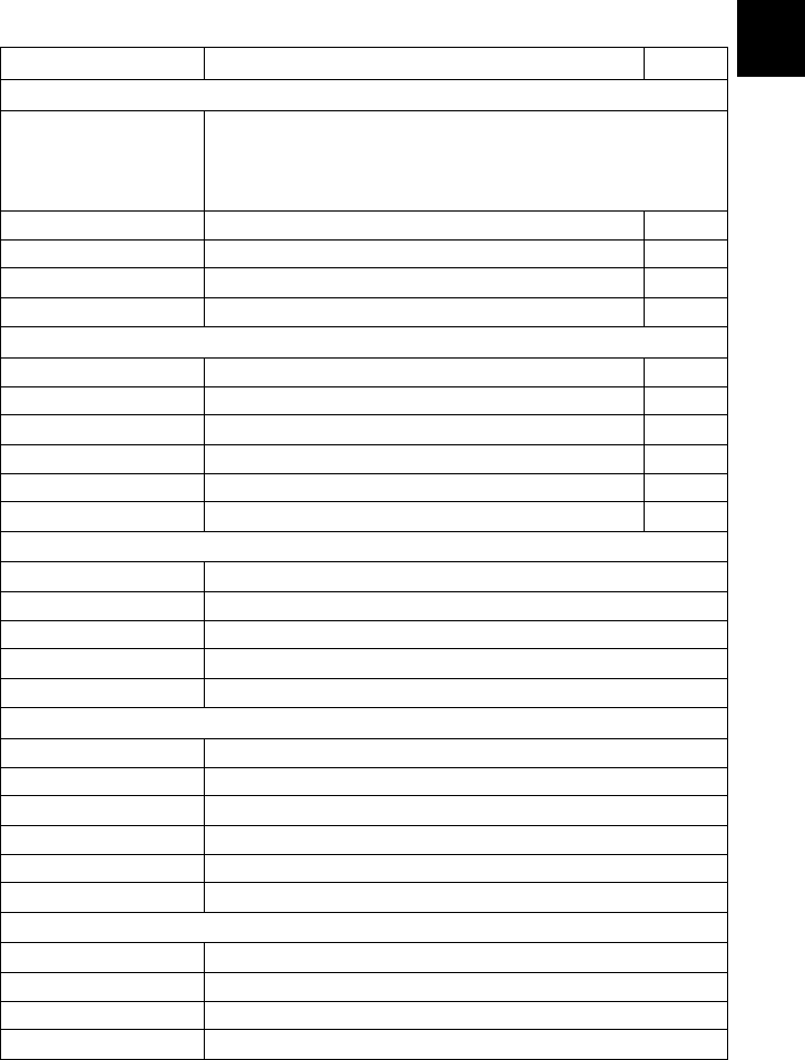
OSD Function Description
Actual on-screen display values may vary with updated versions of the firmware and user setting.
* Only available under S or C video input.
** Only available under VGA input.
Item Function Description Range
Specialty
Color Temperature
RGB adjustment is
available only for
Standard, Arth and
Lap settings)
Choose between color temperatures for Default, Standard, Arth, or Lap
Red Red balance 0-255
Green Green balance 0-255
Blue Blue balance 0-255
Gamma Gamma value 1.6-2.4
Setting
Brightness Increase or decrease the brightness 0-100
Contrast Increase or decrease the contrast 0-100
Phase* Increase or decrease the Phase level 0-100
Chroma* Increase or decrease the Chroma level 0-100
Image Sharpness Set image sharpness from 1 to 10 1-10
Video Sharpness* Increase or decrease the video sharpness 0-100
Image Effect
Scale Mode Choose scale mode between fill screen, V-fill, H-fill, or one to one
Mirror Enable or Disable mirror image
Freeze Frame Enable or Disable freeze frame
Zoom/Pan Enable zoom-in and pan function
PIP Enable PIP (Picture in Picture) function
Advanced
OSD position Control Control OSD Menu Position, Background, and Timeout
Screen Control** Control and adjust Horizontal, Vertical, Frequency, Phase
DPMS Choose DPMS (Display Power Management Signaling)
Auto Source Select Adjust Auto Source Select between on and off.
Recall Factory Default Set to factory default
Key lock Set to Key lock mode
Information
User Name Entry Enter custom username display for boot-up display
Serial Number Display monitor serial number
Runtime Display current run time of monitor
Input Format Display current input format
12
Cleaning the Monitor
Caution Do not expose the monitor to moisture or directly
apply liquid cleaners directly to the screen. Spray the
cleaning solution into a soft cloth and clean gently.
No specific liquid or chemical is necessary for cleaning this
VISIONELECT (model 240-030-930) LCD monitor. Use only non-abrasive
cloths and cleaning solutions to clean similar equipment used in hospitals.
1. Clean the panel with a dry soft cloth, or a soft cloth lightly
moistened with mild detergent solution. Do not use any type of
solvent, such as alcohol or benzine, which might damage the
finish.
2. Apply alcohol to glass surfaces with soft cotton applicator to aid in
cleaning and drying without leaving spots or streaks.
3. Dry thoroughly with soft towel or gauze surgical sponge.
Acceptable cleaning agents for bezel cleaning include:
• Cidex (2.4% glutaraldehyde solution)
• Sodium Hypochlorite (bleach) 10%
• 0.5% Chlorhexidine in 70% isopropyl alcohol
70% isopropyl alcohol is recommended for the screen surface.

13
English
EN
Troubleshooting
Before returning your LCD monitor for service, consult the
troubleshooting list below
Problem Current Status Remedy
No Picture
LED ON Using the OSD, adjust the brightness and contrast
to maximum, or reset them to their default
settings.
LED OFF
Check the power switch.
Check if the AC power cord is properly connected
to the AC adapter.
LED Blinking
Check if the video signal cable is properly
connected at the back of the monitor.
Check if the power to the computer system is ON.
Abnormal
Picture
Oversized or
undersized display;
missing display;
center shift
Using the Auto Setup button, adjust CLOCK,
CLOCK-PHASE, H-POSITION, and V-POSITION
with non-standard signals.
Wait for a few seconds after adjusting the size of
the image before changing or disconnecting the
signal or powering OFF the monitor.
14
Technical Specifications
Display
LCD Monitor Panel 21 inches (533.4mm)
(s/w TFT Active matrix LCD)
Synchronization 2.5 - 5.0 Vpp separated sync
Pixel Pitch 0.270mm
Response Time <25ms
View Angle +/-85° (L/R) × +/-85° (U/D)
Display Colors 16 million colors
Native Resolution 1600 dots × 1200 dots
Input Signal Composite video; S-video;
Analog RGB; DVI
Maximum Pixel Clock 135 MHz × 1
Electrical
Power Adapter AC 100-240V; DC 24V
Power Consumption 90W (max)
Current Direct
Dimensions
Dimensions (W × H × D) 499.66 x 428.88 x 104.25mm
Weight 17 lbs.
VESA Mounting Interface VESA 100mm × 100mm
Operating Conditions
Operating Temperature 41 to 90°F (5 to 32.2°C)
Relative Humidity 10 to 60%
Electrical Input Rating 24V DC 3.75A
Transport & Storage Conditions
Storage (-4 to 140°F) -20 to 60°C
Relative Humidity Range 10 to 85%
Atmospheric Pressure Range 500 to 1060 hPa
15
English
EN
Classification and Approvals
Class I Equipment
Medical equipment with respect to electric shock, fire and mechanical
hazards only in accordance with UL 60601-1 and CAN/CSA C22.2
No. 601.1.
IPX1 Water Ingress Protection
Continuous operation
Warning This equipment is not suitable for use in the presence
of a FLAMMABLE ANESTHETIC MIXTURE WITH AIR, or
WITH OXYGEN OR NITROUS OXIDE.
This monitor is intended for use on Health Care Facilities model
240-030-930.
No user serviceable parts inside. Ask qualified personnel before
accessing internal components.
Caution For disposal of waste product, follow the requirement
of the local code.
This product is considered electronic equipment. It must not be disposed
of as unsorted municipal waste, and must be collected separately. Please
contact the manufacturer or other authorized disposal company to
decommission your equipment.
51 LJ
Medical Equipment
E215822

16
Electromagnetic Compatibility
Like other electrical medical equipment, the VISIONELECT (model 240-
030-930) monitor requires special precautions to ensure electromagnetic
compatibility with other electrical medical devices. To ensure
electromagnetic compatibility (EMC), the VISIONELECT (model
240-030-930) monitor must be installed and operated according to the
EMC information provided in this manual.
Note The VISIONELECT (model 240-030-930) monitor has been
designed and tested to comply with IEC 60601-1-2:2003
requirements for EMC with other devices.
Caution The VISIONELECT (model 240-030-930) monitor may
be interfered with by other equipment, including
portable and mobile RF communication equipment,
even if such equipment meets the applicable
emissions requirements.
Warning Do not use cables or accessories other than those
provided with the VISIONELECT (model 240-030-930)
monitor, as this may result in increased
electromagnetic emissions or decreased immunity to
such emissions.
Warning If the VISIONELECT (model 240-030-930) monitor is
used adjacent to or stacked with other equipment,
observe and verify normal operation of the
VISIONELECT (model 240-030-930) monitor in the
configuration in which it will be used prior to using it in
a surgical procedure. Consult the tables below for
guidance in placing the VISIONELECT (model 240-030-
930) monitor
Warning When this device is connected with other electrical
equipment, leakage currents may be additive. To
minimize total leakage current per patient, ensure that
all systems are installed according to the requirements
of IEC 60601-1.

17
English
EN
Guidance and Manufacturer's Declaration: Electromagnetic Emissions
VISIONELECT (model 240-030-930) monitor is intended for use in the electromagnetic environment
specified below. The customer or the user of VISIONELECT (model 240-030-930) monitor should
ensure that it is used in such an environment.
Emissions test Compliance Electromagnetic Environment - guidance
RF emissions
CISPR11 Group 1
The VISIONELECT (model 240-030-930)
monitor must emit electromagnetic energy in
order to perform its intended function. Nearby
electronic equipment may be affected.
RF emissions
CISPR11 Class B
VISIONELECT (model 240-030-930) monitor is
suitable for use in all establishments, including
domestic establishments and those directly
connected to the public low-voltage power
supply network that supplies buildings used for
domestic purposes.
Harmonic emissions
IEC61000-3-2 Class A
Voltage Fluctuations/
flicker emissions
IEC61000-3-3 Complies

18
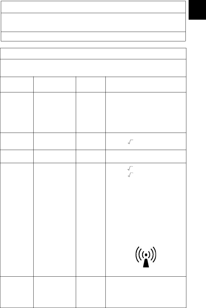
Guidance and Manufacturer's Declaration: Electromagnetic Immunity
VISIONELECT (model 240-030-930) monitor is intended for use in the electromagnetic environment
specified below. The customer or the user of VISIONELECT (model 240-030-930) monitor should
ensure that it is used in such an environment.
Immunity Test IEC 60601 Test
Level Compliance Level Electromagnetic
Environment:
Guidance
Electrostatic Discharge
(ESD)
IEC61000-4-2
±6kV contact
±8kV air ±2,4,6kV contact
±2,4,8kV air
Floors should be
wood, concrete, or
ceramic tile. If floors
are covered with
synthetic material,
the relative humidity
should be at least
30%.
Electrical fast transient/
burst
IEC61000-4-4
±2kV for power
supply lines
±1kV for input/
output lines
±2kV line to ground
±1kV line to line
Mains power quality
should be that of a
typical commercial
or hospital
environment.
Surge
IEC61000-4-5
±1kV differential
mode
±2kV common
mode
±0.5, 1kV
differential mode
±0.5, 1, 2kV
common mode
Mains power quality
should be that of a
typical commercial
or hospital
environment.
Voltage dips, short
interruptions and voltage
variations on power supply
input lines
IEC61000-4-11
<5% Ut (>95% dip
in Ut) for 0.5 cycle
40% Ut (60% dip in
Ut) for 5 cycles
70% Ut (30% dip in
Ut) for 25 cycles
<5% Ut (>95% dip
in Ut) for 5 sec.
<5% Ut (>95% dip
in Ut) for 0.5 cycle
40% Ut (60% dip in
Ut) for 5 cycles
70% Ut (30% dip in
Ut) for 25 cycles
<5% Ut (>95% dip
in Ut) for 5 sec.
Mains power quality
should be that of a
typical commercial
or hospital
environment. If the
user of
VISIONELECT
(model 240-030-
930) monitor
requires continued
operation during
power mains
interruptions, it is
recommended that
VISIONELECT
(model 240-030-
930) monitor be
powered from an
uninterruptible
power supply or a
battery.
Power frequency (50/60Hz)
magnetic field
IEC 61000-4-8 3 A/m N/A
Power-frequency
magnetic fields
should be at levels
characteristic of a
typical location in a
typical commercial
or hospital
environment.
19
English
EN
NOTE: Ut is the AC mains voltage prior to application of the test level.
Guidance and Manufacturer's Declaration: Electromagnetic Immunity
VISIONELECT (model 240-030-930) monitor is intended for use in the electromagnetic environment
specified below. The customer or the user of VISIONELECT (model 240-030-930) monitor should
ensure that it is used in such an environment.
Immunity
Test IEC 60601 Test
Level Compliance
Level Electromagnetic Environment:
Guidance
Portable and mobile RF communications
equipment should be used no closer to
any part of the VISIONELECT (model
240-030-930) monitor system, including
its cables, than the recommended
separation distance calculated from the
equation applicable to the frequency of
the transmitter.
Conducted RF
IEC 61000-4-6 3 Vrms
150 kHz to 80 MHz 3 V Recommended Separation Distance
Radiated RF
IEC 61000-4-3 3 V/m
80MHz to 2.5 GHz 3 V/m
80 MHz to 800 MHz
800 MHz to 2.5 GHz
where P is the maximum output power
rating of the transmitter in watts (W)
according to the transmitter manufacturer
and d is the recommended separation
distance in meters (m).
Field strengths from fixed RF transmitters,
as determined by an electromagnetic site
survey (a), should be less than the
compliance level in each frequency
range(b).
Interference may occur in the vicinity of
equipment marked with the following
symbol:
NOTE 1: At 80
MHz and 800
MHz, the
higher
frequency
range applies.
Guidance and Manufacturer's Declaration: Electromagnetic Immunity
VISIONELECT (model 240-030-930) monitor is intended for use in the electromagnetic environment
specified below. The customer or the user of VISIONELECT (model 240-030-930) monitor should
ensure that it is used in such an environment.
d1.17P=
d1.17P=
d2.33P=

20
NOTE 2: These guidelines may not apply in all situations. Electromagnetic propagation is affected by
absorption and reflection from structures, objects, and people.
(a) Field strengths from fixed transmitters, such as base stations for radio (cellular/cordless)
telephones and land mobile radios, amateur radio, AM and FM radio broadcast, and TV broadcast,
cannot be predicted theoretically with accuracy. To assess the electromagnetic environment due to
fixed RF transmitters, an electromagnetic site survey should be considered. If the measured field
strength in the location in which theVISIONELECT (model 240-030-930) monitor system is used
exceeds the applicable RF compliance level above, the VISIONELECT (model 240-030-930) monitor
system should be observed to verify normal operation. If abnormal performance is observed,
additional measures may be necessary, such as reorienting or relocating the VISIONELECT monitor
VISIONELECT (model 240-030-930) monitor unit.
(b) Over the frequency range 150 kHz to 80 MHz, field strengths should be less than 3 V/m.
Guidance and Manufacturer's Declaration: Electromagnetic Immunity
VISIONELECT (model 240-030-930) monitor is intended for use in the electromagnetic environment
specified below. The customer or the user of VISIONELECT (model 240-030-930) monitor should
ensure that it is used in such an environment.

21
English
EN
Recommended Separation Distances Between Portable and Mobile RF Communications
Equipment and the VISIONELECT (model 240-030-930) monitor System
The VISIONELECT (model 240-030-930) monitor system is intended for use in an electromagnetic
environment in which radiated RF disturbances are controlled. The user of the VISIONELECT (model
240-030-930) monitor system can help prevent electromagnetic interference by maintaining a
minimum distance between portable and mobile RF communications equipment (transmitters) and
the VISIONELECT (model 240-030-930) monitor system as recommended below, according to the
maximum output power of the communications equipment.
Rated maximum output
power (W) of transmitter
Separation distance (m) according to frequency of transmitter
150 kHz to 80 MHz 80 MHz to 800 MHz 800 MHz to 2.5 GHz
0.01 0.12 0.12 0.23
0.1 0.37 0.37 0.74
11.171.172.33
10 3.70 3.70 7.37
100 11.70 11.70 23.30
For transmitters rated at a maximum output power not listed above, the recommended separation
distance (d) in meters (m) can be estimated using the equation applicable to the frequency of the
transmitter, where P is the maximum output power rating of the transmitter in watts (W) according to
the transmitter manufacturer.
NOTE 1: At 80 MHz and 800 MHz, the separation distance for the higher frequency range applies.
NOTE 2: These guidelines may not apply in all situations. Electromagnetic propagation is affected by
absorption and reflection from structures, objects, and people.
d1.17P=d1.17P=d2.33P=
22
Warranty
This Stryker Endoscopy product is warranted to the original purchaser for
a period of one year from the date of purchase to be free from defects in
material and workmanship.
This warranty extends to all purchases and is limited to the repair or
replacement of the product without charge when returned in the original
shipping case to:
Stryker Endoscopy
5900 Optical Court
San Jose, CA 95138
USA
Stryker Endoscopy cannot accept responsibility for returns or
replacements which have not been authorized. This warranty does not
cover damages caused by misuse or by failure to follow the procedures
outlined in this manual or demonstrated by Stryker Endoscopy
representatives.
There are no other expressed warranties.
Service and Claims
Do not attempt to service this product yourself. If service is needed either
during or after the warranty period, contact Stryker Endoscopy at
1-800-624-4422, or phone your local Stryker Endoscopy sales
representative.

23
Declaration of Conformity
Manufacturer:
Stryker Endoscopy
5900 Optical Court
San Jose, CA 95138
USA
1-800-624-4422
1-408-754-2000
Product Designation: VISIONELECT (model 240-030-930) 21" High
Definition LCD Monitor
The above product complies with the requirements of EC Directive 93/42/
EEC. This declaration is based on compliance testing to:
EN 60601-1/08-90
EN 60601-1 A1/05-93
EN 60601-1 A2/06-95
This document is on file.
The CE mark will be affixed based on directive 93/42/EEC.
Stryker European Representative
Regulatory Manager, Stryker France
ZAC Satolas Green Pusignan
Av. de Satolas Green
69881 MEYZIEU Cedex, France
Stryker and Stryker Endoscopy are registered trademarks of Stryker Corporation.
24
2006/05 www.stryker.com 1000-400-895 A
Stryker Endoscopy
5900 Optical Court
San Jose, CA 95138 USA
1-408-754-2000, 1-800-624-4422
www.stryker.com
European Representative:
Regulatory Manager, Stryker France
ZAC Satolas Green Pusignan
Av. De Satolas Green
69881 MEYZIEU Cedex, France