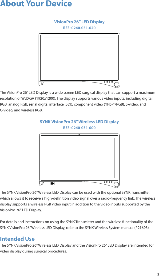
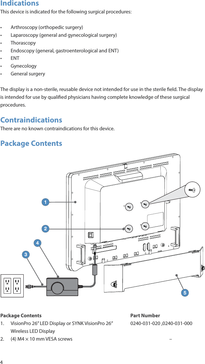
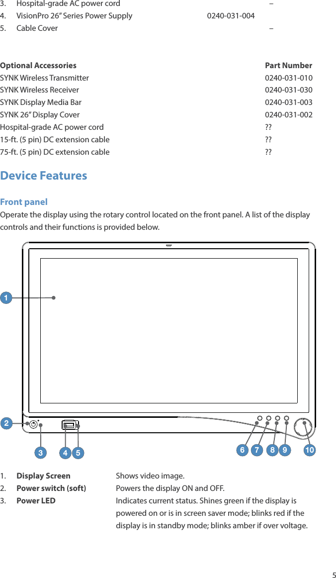
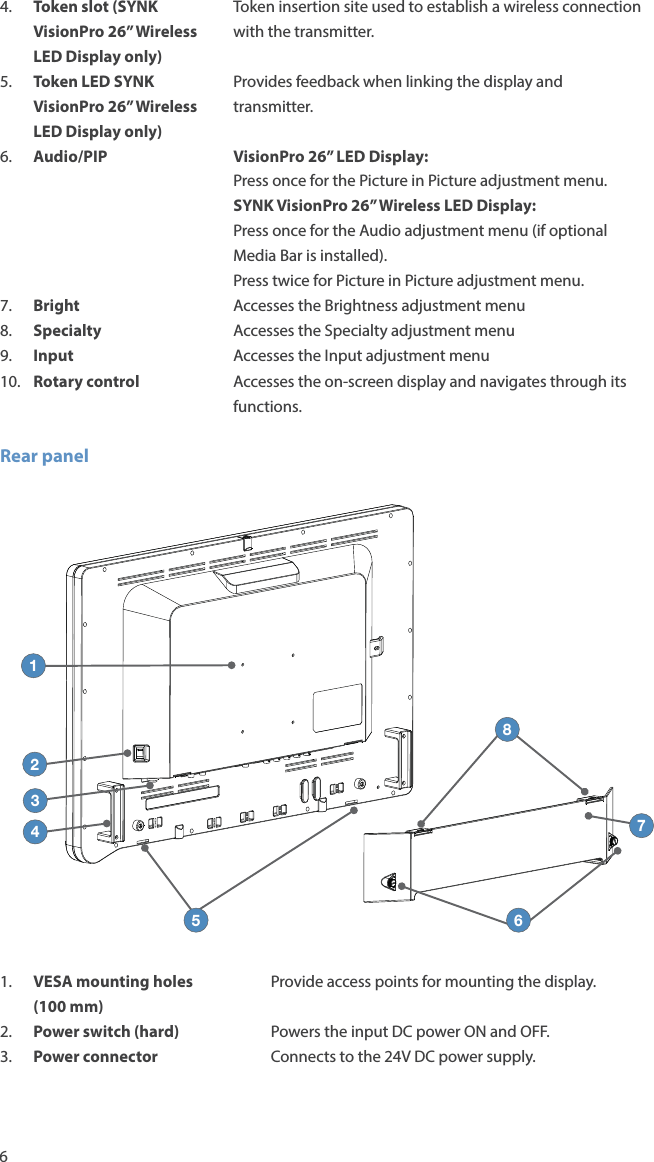
BARCO AMM261WTDSW 26inch Wireless LED Display User Manual P22286A Book indb
Advan Int'l Corp. 26inch Wireless LED Display P22286A Book indb
UserManual.wiki
>
BARCO
>
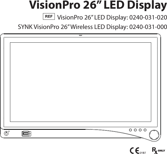
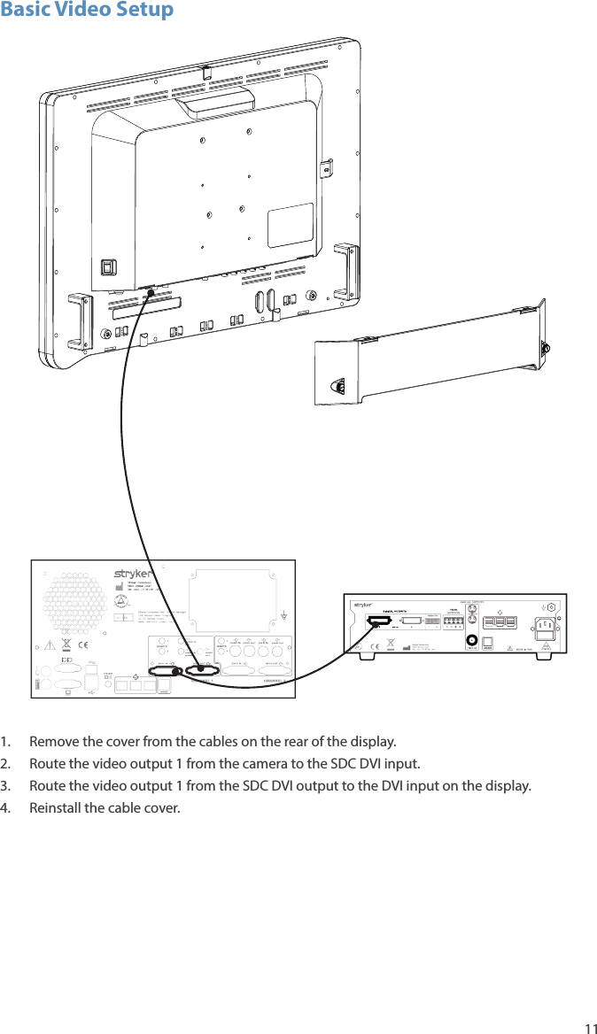
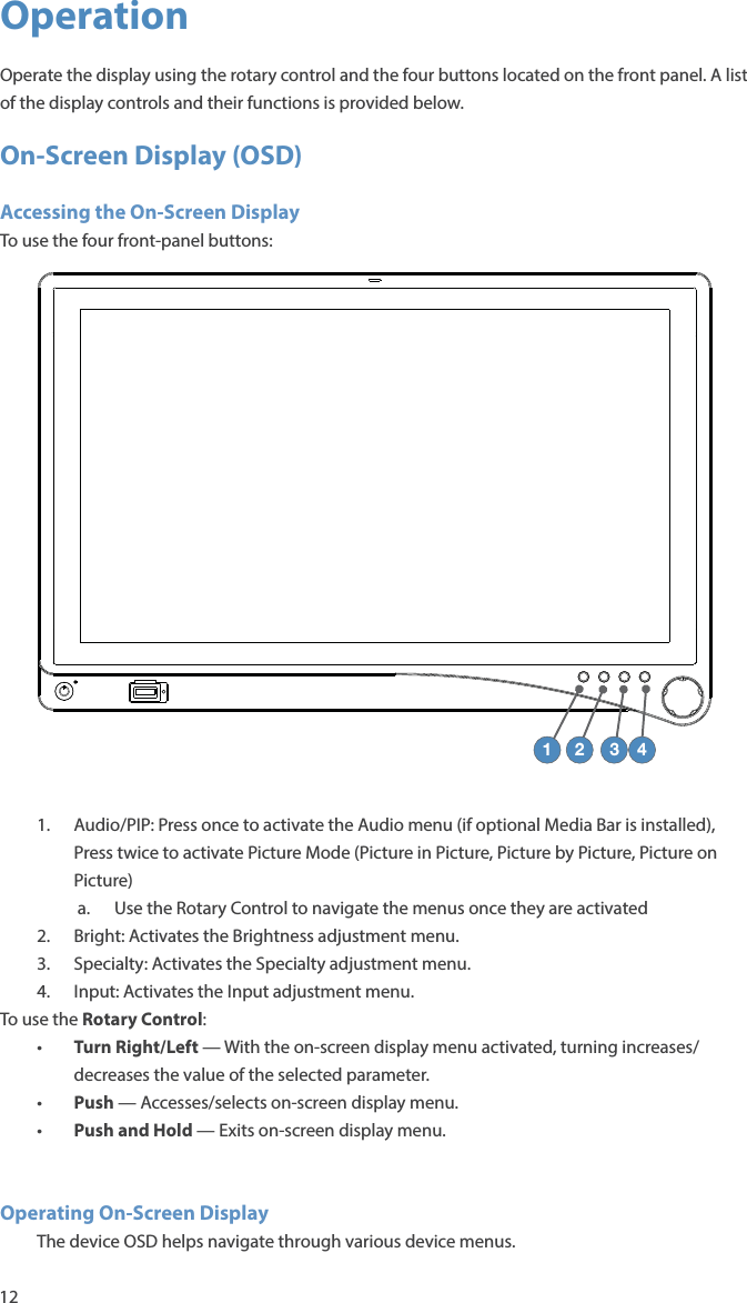
AMM261WTDSW User Manual
User manual
Navigation menu
Upload a User Manual
Namespaces
Wiki Guide
HTML
PDF
Info
Views
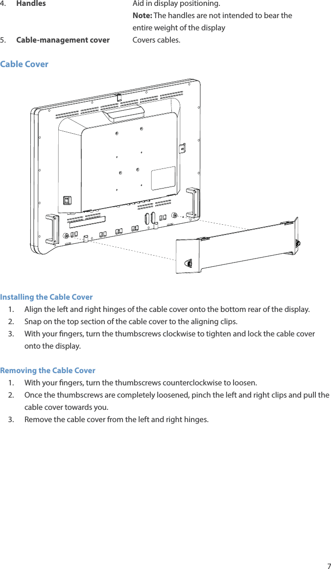
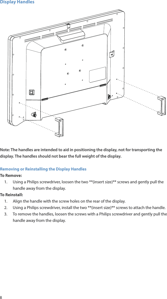
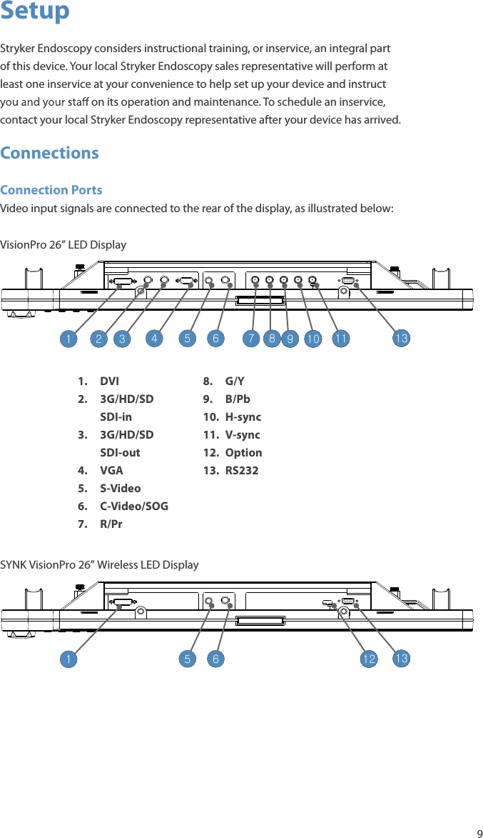
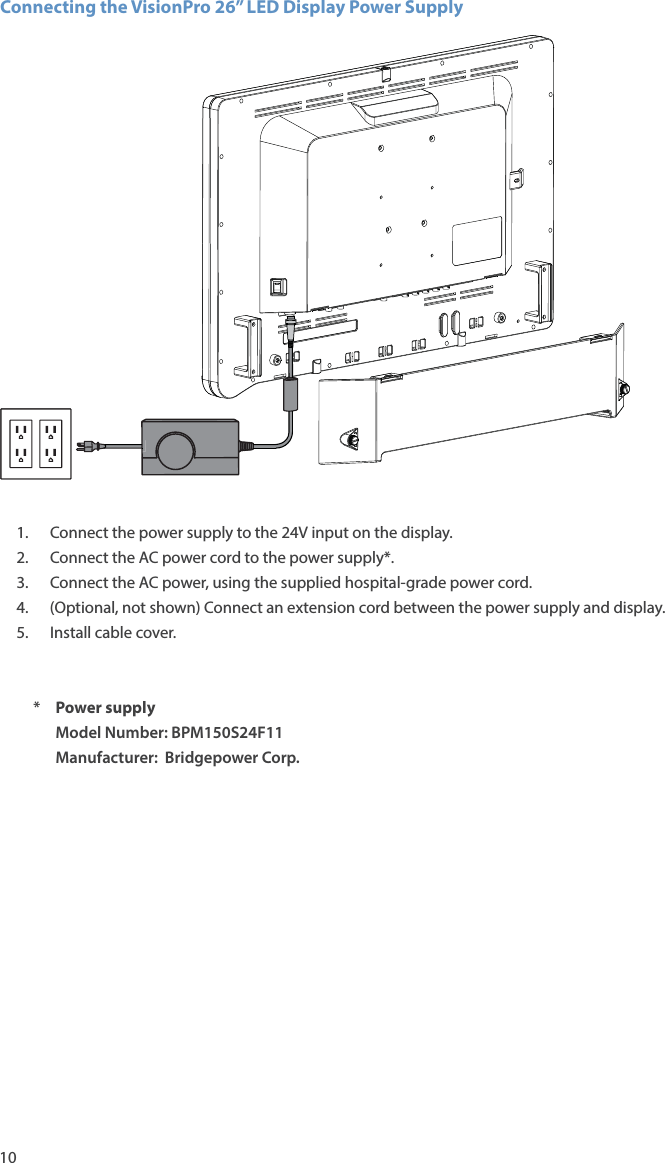
User Manual
Discussion / Help
Navigation