BBM Electronics Group 6KLTX Wireless microphone transmitter belt pack User Manual S6000 belt instructions V1 2
BBM Electronics Group Ltd Wireless microphone transmitter belt pack S6000 belt instructions V1 2
UserManual.wiki
>
BBM Electronics Group
>
6KLTX User Manual
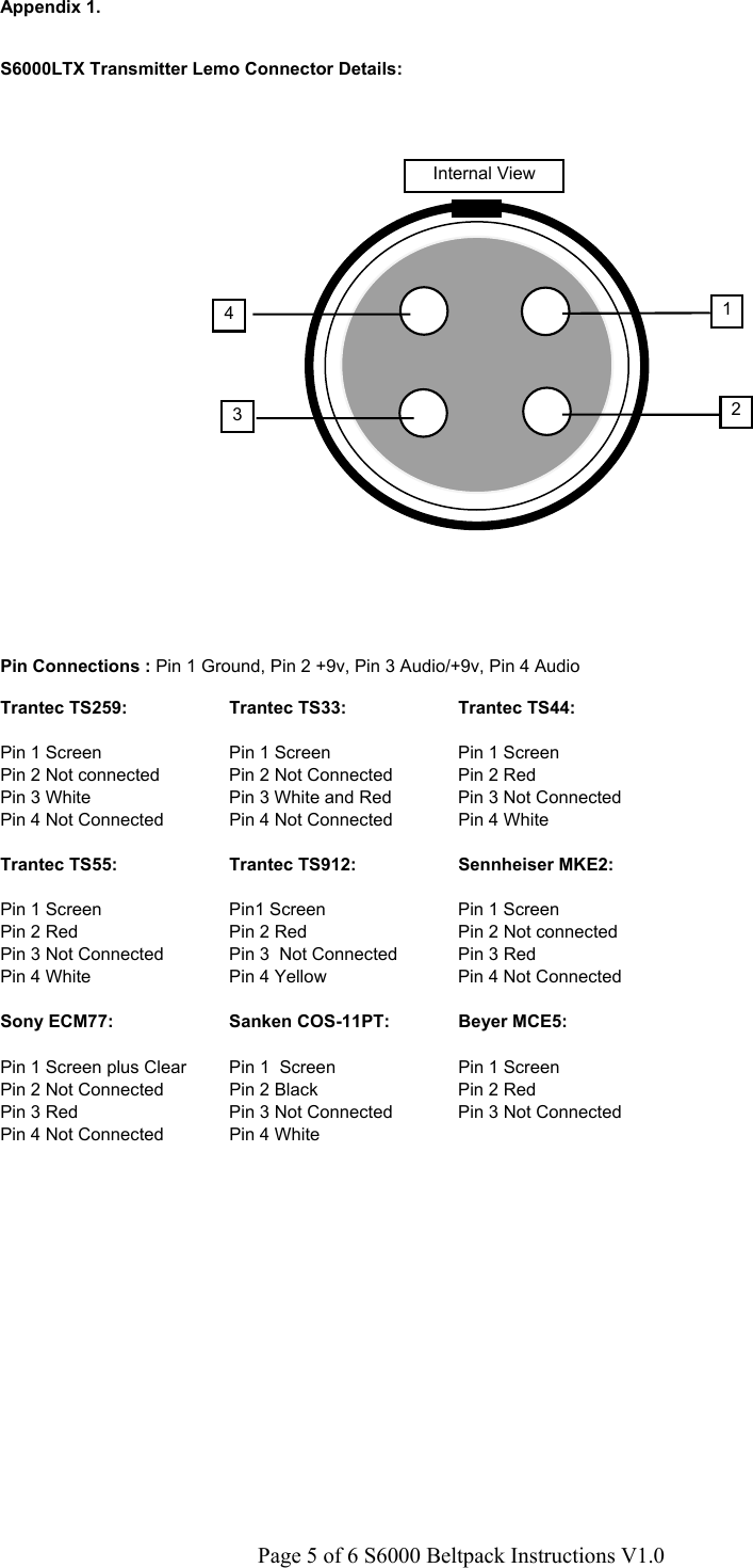
Instructions
Navigation menu
Upload a User Manual
Namespaces
Wiki Guide
HTML
PDF
Info
Views
User Manual
Discussion / Help
Navigation